Embed Size (px)
Citation preview
POLITECNICO DI MILANO
Facoltà di Ingegneria dei Processi Industriali
Corso di Laurea Specialistica in Ingegneria dei Materiali
Hot ductility of Nb-V microalloyed steels
Relatore: Prof. Maurizio VEDANI
Tesi di Laurea Specialistica di:
Su Lian
Matr. 722604
1
Matr. 722604
Su Lian
Academic year: 2009/2010
Content
Abstract ............................................................................................................................................... 3
Chapter 1 Introduction ................................................................................................................... 4
1.1. Background ................................................................................................................................... 4
1.1.1. High strength low alloy (HSLA) steels ........................................................................................ 4
1.1.2. Microalloyed steel ..................................................................................................................... 5
1.1.3. Application ................................................................................................................................ 7
1.1.3.1. Microalloyed steel in offshore application and petroleum industry ..................................... 7
1.1.3.2. Microalloyed steel in automobile industry ............................................................................ 9
1.1.3.3. Constructional microalloyed steel ........................................................................................ 11
1.1.4. Typical microalloyed steel ....................................................................................................... 12
1.1.4.1. Niobium and niobium contained microalloyed steel ........................................................... 12
1.1.4.2. Vanadium and Vanadium contained microalloyed steel ..................................................... 22
1.1.4.3. Titanium and Titanium contained microalloyed steel. ...................................................... 26
1.2. Hot Ductility ................................................................................................................................ 27
1.2.1. Variations influence the hot ductility ...................................................................................... 27
1.2.1.1. Influence of niobium and vanadium to hot ductility ............................................................ 28
1.2.1.2. Influence of Titanium on hot ductility .................................................................................. 31
1.2.1.3. Influence of aluminum on hot ductility ................................................................................ 32
1.2.2 Hot ductility during continuous casting ................................................................................... 32
1.3. Research Purpose ....................................................................................................................... 35
Chapter 2: Experimental procedure and result analysis ................................................................... 36
2
2.1. Microalloyed Steels Rolled and as cast structure of type D and type F ..................................... 36
2.2. Procedure for rolling .................................................................................................................. 37
2.3. Sample preparation .................................................................................................................... 38
2.4. Microstructure analysis of F and D typed before tensile test .................................................... 40
2.5. Hot tensile test ........................................................................................................................... 44
2.6. Illustration analysis for hot tensile test result ............................................................................ 47
2.6.1. Strengthen hardening by Nb ................................................................................................... 47
2.6.2. Hot ductility behavior analysis ................................................................................................ 50
2.7. Optical microscopy analysis ....................................................................................................... 55
2.7.1. Microstructure analysis of as cast steel .................................................................................. 56
2.7.2. Microstructure analysis of hot rolled steel ............................................................................. 60
Chapter 3 Discussion and conclusion ................................................................................................ 64
References ......................................................................................................................................... 66
3
Abstract
Microalloyed steel has become a good option in industry application for its high
strength and low weight. However hot ductility problems exist during high temperature
deformation which limit the commercial usage. Therefore, in this study, the hot
ductility behavior of Niobium and Vanadium contained microalloyed steel with as cast
structure and hot rolled structure were investigated by hot tensile test in the
temperature region from 800℃ to 1000℃, followed by fracturing and rapid quenching.
Reduction of Area was recorded as an important parameter representing the hot
ductility. High temperature yield strength, Ultimate tensile strength and elongation
were obtained for study the hardening effect of microalloyed elements. Analyses of
microstructure damage during tensile test were performed with optical microscope.
Cracks were observed to understand the detrimental influence of Niobium and
Vanadium on hot ductility. It was detected that the critical temperature zone for this
microalloyed steel is between 850℃ and 950℃, the rolled steel has better ductility
performance than as cast steel, and rolling procedure may reduce the negative effect
of Nb and V on hot ductility.
4
Hot ductility of Nb-V microalloyed steels
Chapter 1 Introduction
1.1 Background
1.1.1 High strength low alloy (HSLA) steels
High strength low alloy (HSLA) steels have been developed since the 1960s
originally for large diameter oil and gas pipelines. Generally, it is a class of steels
designed to achieve specific properties by controlled thermomechanical processing.
Varying from other steels they are not made to meet a specific chemical composition,
but rather to specific mechanical properties. They have a carbon content between
0.05–0.25% to retain formability and weldability. Other alloying elements include up to
2.0% manganese and small quantities of copper, nickel, niobium, nitrogen, vanadium,
chromium, molybdenum, titanium, calcium, rare earth elements, or zirconium, of
which copper, titanium, vanadium, and niobium are added for strengthening purposes.
Most HSLA are microalloyed steels.
The elements added into are intended to alter the microstructure of carbon steels,
which is usually a ferrite-pearlite aggregate, to produce a very fine dispersion of alloy
carbides in an almost pure ferrite matrix. On one hand, this maintains and increases
the material's strength by refining the grain size, which in the case of ferrite increases
yield strength by 50%, and on the other hand, precipitation strengthening plays a
minor role. Their yield strengths can be anywhere between 250–590 MPa. Due to
their higher strength and toughness HSLA steels usually require 25 to 30% more
energy to form, as compared to carbon steels.
According to its high strength and stiffness, HSLA is widely used in automotive
industry to replace low-carbon steel parts with thinner cross-section parts for reduced
5
weight without sacrificing strength and dent resistance. Trucks, construction
equipment, off-highway vehicles, mining equipment, and other heavy-duty vehicles
use HSLA sheets or plates for chassis components, buckets, grader blades, and
structural members outside the body. In equipment such as power cranes, cement
mixers, farm machinery, trucks, trailers, and power-transmission towers, HSLA bar,
minimum yield strength ranging from 350 to 500 MPa is used.
Accompany to the strength increasing from 250 to 550 MPa, a 30 to 40% loss in
ductility occurs, which require 25 to 30% more energy when operation on HSLA steel
than structural carbon steels. Another disadvantage is that HSLA steels have
directionally sensitive properties, which means formability and impact strength can
vary significantly when tested longitudinally and transversely to the grain. This is
because bends that are parallel to the longitudinal grain are more likely to crack
around the outer edge since it experiences tensile loads. By adding Copper, silicon,
nickel, chromium, and phosphorus to increase corrosion resistance, adding Zirconium,
calcium, and rare earth elements for sulfide-inclusion shape control which increases
formability, this directional characteristic is substantially reduced.
1.1.2 Microalloyed steel
From functional point of view, HSLA can be divided into 4 types, Weathering steels,
Control-rolled steels, Pearlite-reduced steels and Microalloyed steels. Most HSLA are
microalloyed steels and it has the most widely applications.
As we have mentioned before, Microalloyed steel contain small amounts of
vanadium, niobium, titanium, molybdenum, zirconium, boron, and rare-earth metals,
Individual elements generally less than 0.1% and total microalloying elements
generally less than 0.15%. They are used to refine the grain microstructure and
facilitate precipitation hardening. Performance and cost of these steels are between
carbon steel and low alloy steel. Yield strength is between 500 and 750 MPa without
heat treatment. Weldability is good, and can even be improved by reducing carbon
content while maintaining strength. Fatigue life and wear resistance are superior to
6
similar heat-treated steels. The disadvantages are that the ductility and toughness are
not as good as the quenched and tempered (Q&T) steels. Also, they must be heated
hot enough for all of the microadditions to be in solution; after formed, the material
must be quickly cooled to 540 to 600 °C.
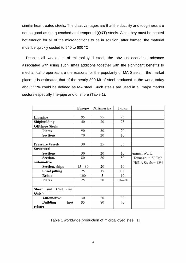
Despite all weakness of microalloyed steel, the obvious economic advance
associated with using such small additions together with the significant benefits to
mechanical properties are the reasons for the popularity of MA Steels in the market
place. It is estimated that of the nearly 800 Mt of steel produced in the world today
about 12% could be defined as MA steel. Such steels are used in all major market
sectors especially line-pipe and offshore (Table 1).
Table 1 worldwide production of microalloyed steel [1]
7
1.1.3 Application
Microalloying technology, developed for the production of flat products (plate, strip
and line pipe) during the 1960’s and 1970’s, has been applied to “long products” such
as engineering bars, sections, forgings and wire rod since about 1980. In the 1980’s
the main rationale to use niobium bearing steel bars and wires was to eliminate the
need for a hardening process, i.e. quenching and tempering, in manufacturing
heat-treated steel parts without any trade off in properties. After entering 21st century,
a global trend of steelmaking increasing occurs within developing countries, which
leads to supply and demand unbalance of raw material. The resulting shortages in
raw materials, energy and means of transportation contributed to raising prices. From
sustainable point of view, on one hand satisfying the engineering needs, on the other
hand costing less steel, Microalloyed steel has taken a leading role in modern
manufacturing field. By contributing to a "sustainable" growth rate of steel production,
microalloyed steels fulfill a new role: they create economic value and wealth. To
achieve global economic goals of underdeveloped countries, substitution may be a
necessity, rather than an option.
Microalloyed steels are used in automobile industries, offshore platforms and in
structural applications.
1.1.3.1 Microalloyed steel in offshore application and petroleum industry
Oil and gas industry is one of the main consumer for High Strength Low Alloy and
microalloyed steel. The consumption on petroleum pipeline takes 1/5 of the whole
investment of petroleum industry every year.
For economic consideration, oil and gas pipeline is the most economical way in long
distance petroleum transportation, which leads to the blooming of pipeline building in
the past century, and 10 million tons of steel are consumed in the petroleum pipeline
manufacturing every year.
8
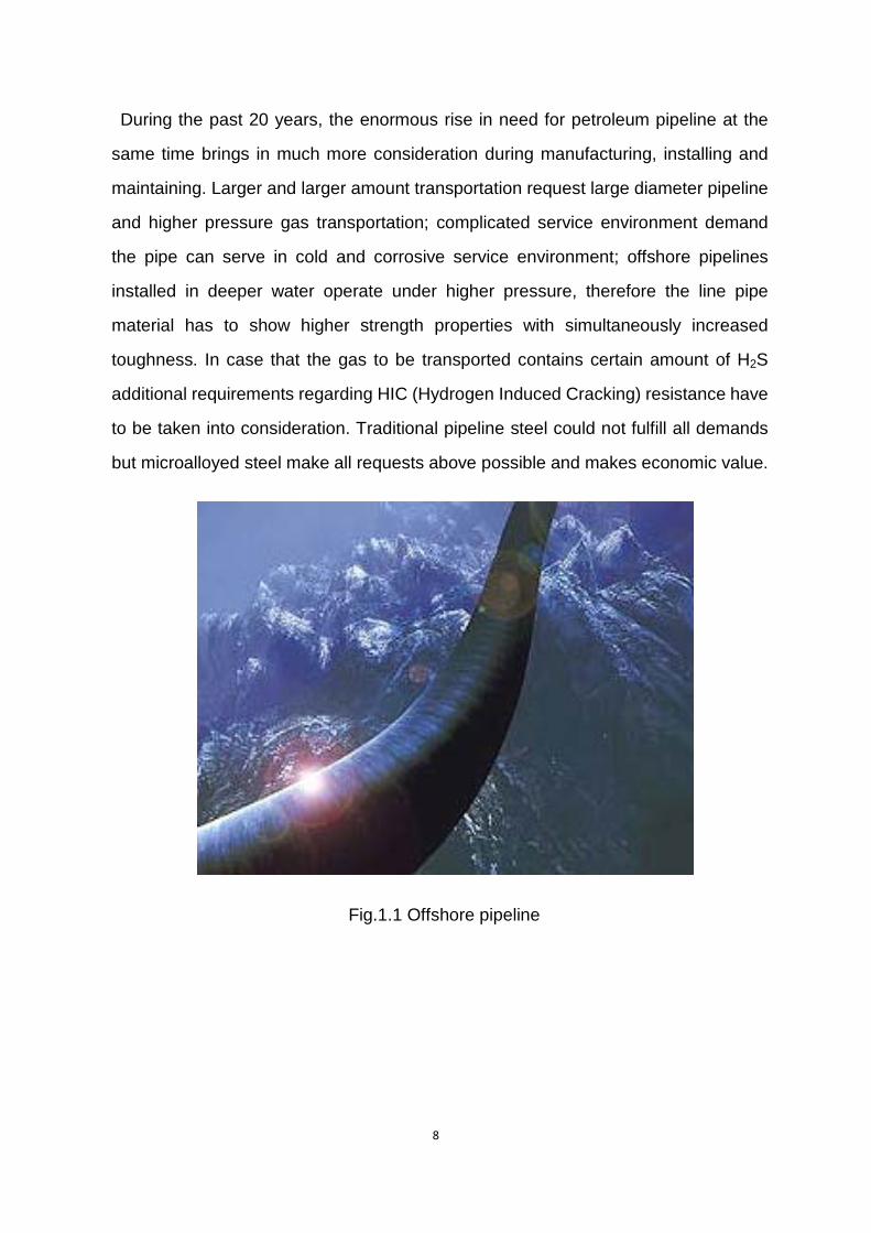
During the past 20 years, the enormous rise in need for petroleum pipeline at the
same time brings in much more consideration during manufacturing, installing and
maintaining. Larger and larger amount transportation request large diameter pipeline
and higher pressure gas transportation; complicated service environment demand
the pipe can serve in cold and corrosive service environment; offshore pipelines
installed in deeper water operate under higher pressure, therefore the line pipe
material has to show higher strength properties with simultaneously increased
toughness. In case that the gas to be transported contains certain amount of H2S
additional requirements regarding HIC (Hydrogen Induced Cracking) resistance have
to be taken into consideration. Traditional pipeline steel could not fulfill all demands
but microalloyed steel make all requests above possible and makes economic value.
Fig.1.1 Offshore pipeline
9
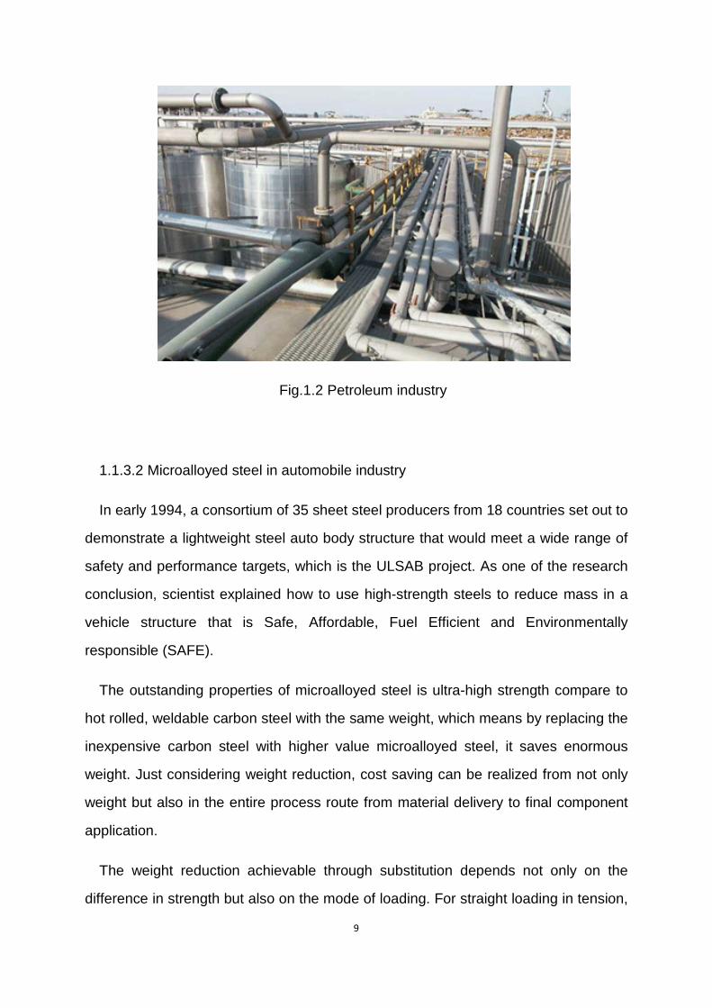
Fig.1.2 Petroleum industry
1.1.3.2 Microalloyed steel in automobile industry
In early 1994, a consortium of 35 sheet steel producers from 18 countries set out to
demonstrate a lightweight steel auto body structure that would meet a wide range of
safety and performance targets, which is the ULSAB project. As one of the research
conclusion, scientist explained how to use high-strength steels to reduce mass in a
vehicle structure that is Safe, Affordable, Fuel Efficient and Environmentally
responsible (SAFE).
The outstanding properties of microalloyed steel is ultra-high strength compare to
hot rolled, weldable carbon steel with the same weight, which means by replacing the
inexpensive carbon steel with higher value microalloyed steel, it saves enormous
weight. Just considering weight reduction, cost saving can be realized from not only
weight but also in the entire process route from material delivery to final component
application.
The weight reduction achievable through substitution depends not only on the
difference in strength but also on the mode of loading. For straight loading in tension,
10
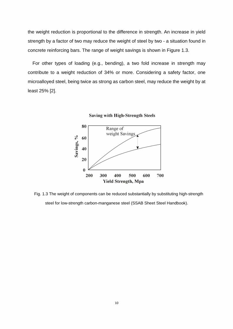
the weight reduction is proportional to the difference in strength. An increase in yield
strength by a factor of two may reduce the weight of steel by two - a situation found in
concrete reinforcing bars. The range of weight savings is shown in Figure 1.3.
For other types of loading (e.g., bending), a two fold increase in strength may
contribute to a weight reduction of 34% or more. Considering a safety factor, one
microalloyed steel, being twice as strong as carbon steel, may reduce the weight by at
least 25% [2].
Fig. 1.3 The weight of components can be reduced substantially by substituting high-strength
steel for low-strength carbon-manganese steel (SSAB Sheet Steel Handbook).
11
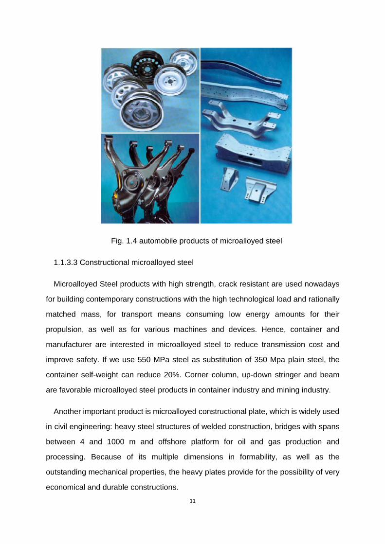
Fig. 1.4 automobile products of microalloyed steel
1.1.3.3 Constructional microalloyed steel
Microalloyed Steel products with high strength, crack resistant are used nowadays
for building contemporary constructions with the high technological load and rationally
matched mass, for transport means consuming low energy amounts for their
propulsion, as well as for various machines and devices. Hence, container and
manufacturer are interested in microalloyed steel to reduce transmission cost and
improve safety. If we use 550 MPa steel as substitution of 350 Mpa plain steel, the
container self-weight can reduce 20%. Corner column, up-down stringer and beam
are favorable microalloyed steel products in container industry and mining industry.
Another important product is microalloyed constructional plate, which is widely used
in civil engineering: heavy steel structures of welded construction, bridges with spans
between 4 and 1000 m and offshore platform for oil and gas production and
processing. Because of its multiple dimensions in formability, as well as the
outstanding mechanical properties, the heavy plates provide for the possibility of very
economical and durable constructions.
12
Here are an example of welded heavy microallyed plates used in bridge with big
spans (more than 150m):
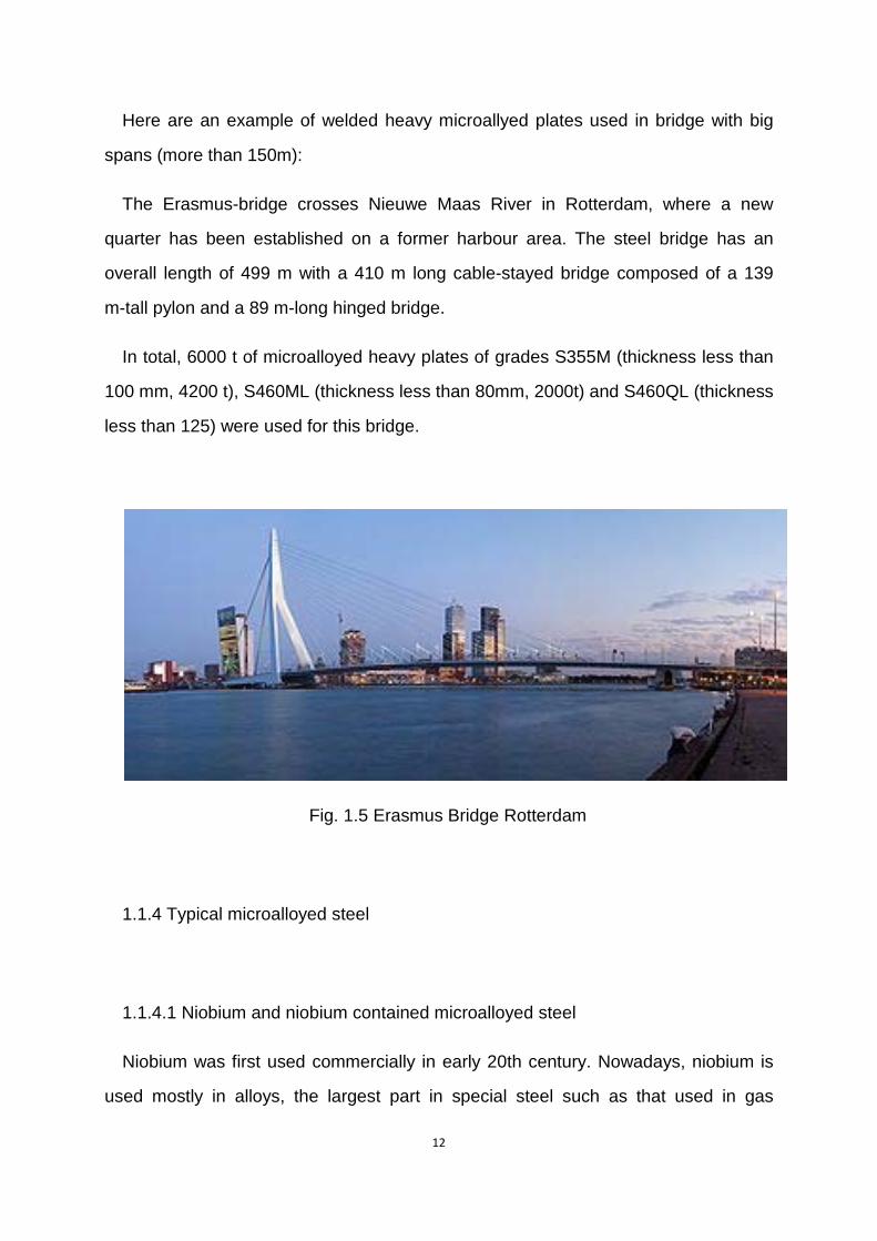
The Erasmus-bridge crosses Nieuwe Maas River in Rotterdam, where a new
quarter has been established on a former harbour area. The steel bridge has an
overall length of 499 m with a 410 m long cable-stayed bridge composed of a 139
m-tall pylon and a 89 m-long hinged bridge.
In total, 6000 t of microalloyed heavy plates of grades S355M (thickness less than
100 mm, 4200 t), S460ML (thickness less than 80mm, 2000t) and S460QL (thickness
less than 125) were used for this bridge.
Fig. 1.5 Erasmus Bridge Rotterdam
1.1.4 Typical microalloyed steel
1.1.4.1 Niobium and niobium contained microalloyed steel
Niobium was first used commercially in early 20th century. Nowadays, niobium is
used mostly in alloys, the largest part in special steel such as that used in gas
13
pipelines and in various superconducting materials because its highest critical
temperature of the elemental superconductors at atmospheric pressure. Besides,
niobium plays a precipitation-hardening role in nickel-, cobalt-, and iron-base
superalloys, which are widely used in Aeronautics and space technology such as jet
engine components, gas turbines, rocket subassemblies, and heat resisting and
combustion equipment. Furthermore, niobium alloy are lightweight and hypoallergenic
(no skin reactions), suitable for jewelry production.
Niobium has threefold influence on the mechanical properties of steel, grain size
refinement during thermomechanical hot forming, lowering the Ar3 transformation
temperature and precipitation hardening. To realize the grain refinement, Niobium
prevent or delay recrystallization in last steps of hot forming; flattened grains as well
as a high dislocation density of the austenite enhance ferrite nucleation. At the same
time of lowering Ar3 temperature, Niobium enhance the ferrite nucleation rate and
reduce grain growth rate, which lead to particular fine-grained transformation
structure.
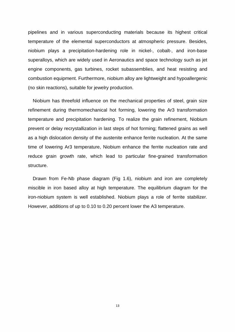
Drawn from Fe-Nb phase diagram (Fig 1.6), niobium and iron are completely
miscible in iron based alloy at high temperature. The equilibrium diagram for the
iron-niobium system is well established. Niobium plays a role of ferrite stabilizer.
However, additions of up to 0.10 to 0.20 percent lower the A3 temperature.
14
Fig. 1.6 Nb-Fe phase diagram
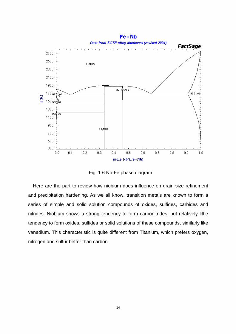
Here are the part to review how niobium does influence on grain size refinement
and precipitation hardening. As we all know, transition metals are known to form a
series of simple and solid solution compounds of oxides, sulfides, carbides and
nitrides. Niobium shows a strong tendency to form carbonitrides, but relatively little
tendency to form oxides, sulfides or solid solutions of these compounds, similarly like
vanadium. This characteristic is quite different from Titanium, which prefers oxygen,
nitrogen and sulfur better than carbon.
15
Fig.1.7. The tendency of certain metals to form oxides, sulfides, carbides, and
nitrides and their precipitation-strengthening potential (arranged similar to the periodic
table) [3].
As talking about the compound form between transition metal and metalloid,
M(transition metal) dissolved in austenite gets restrained at a certain temperature T
with metalloid X into the interstitial phase MX with the cubic lattice of the NaCl type
according to the reaction:
[M] + [X] = MX, (1)
Where [M] and [X] are microaddition M (Nb, Ti, V, Zr or B) and the metalloid X (N or
C) portions respectively, dissolved in the solid solution γ at the temperature T, K.
Solubility of the MX phases in the solid solution allowing for the activation energy of
their nucleation (dissolving) is described by the relationship:
16
log [M][X] = A – B/T, (2)
Where A consist of activation energy of MX phases and temperature, and B depend
on the constant of phase type [4].
Making it possible to evaluate the temperatures of the beginning and end of the MX
phase precipitation at a certain concentration of the microaddition M introduced into
the steel. Knowledge of the temperatures of the beginning and end of precipitation of
the MX phases in austenite is very important for designing the hot-working conditions
for the microalloyed steel.
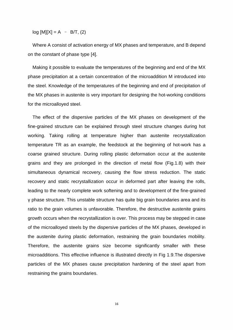
The effect of the dispersive particles of the MX phases on development of the
fine-grained structure can be explained through steel structure changes during hot
working. Taking rolling at temperature higher than austenite recrystallization
temperature TR as an example, the feedstock at the beginning of hot-work has a
coarse grained structure. During rolling plastic deformation occur at the austenite
grains and they are prolonged in the direction of metal flow (Fig.1.8) with their
simultaneous dynamical recovery, causing the flow stress reduction. The static
recovery and static recrystallization occur in deformed part after leaving the rolls,
leading to the nearly complete work softening and to development of the fine-grained
γ phase structure. This unstable structure has quite big grain boundaries area and its
ratio to the grain volumes is unfavorable. Therefore, the destructive austenite grains
growth occurs when the recrystallization is over. This process may be stepped in case
of the microalloyed steels by the dispersive particles of the MX phases, developed in
the austenite during plastic deformation, restraining the grain boundaries mobility.
Therefore, the austenite grains size become significantly smaller with these
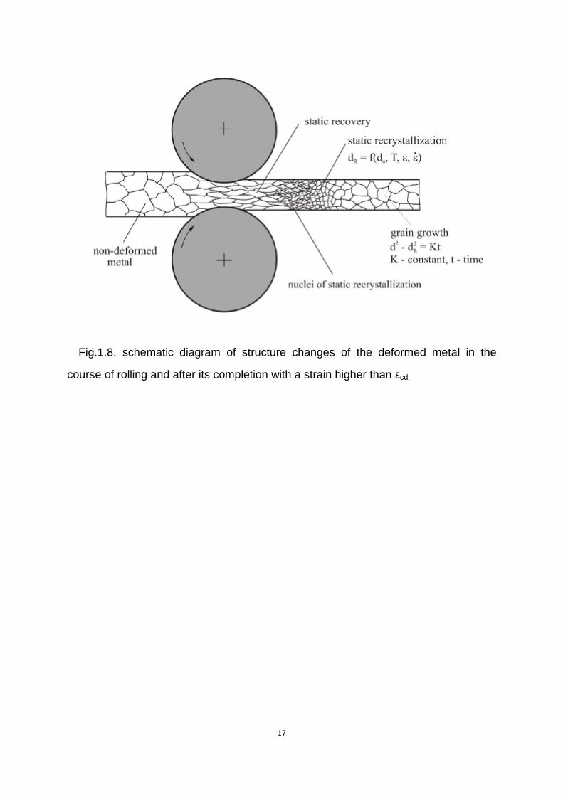
microadditions. This effective influence is illustrated directly in Fig 1.9.The dispersive
particles of the MX phases cause precipitation hardening of the steel apart from
restraining the grains boundaries.
17
Fig.1.8. schematic diagram of structure changes of the deformed metal in the
course of rolling and after its completion with a strain higher than εcd.
18
Fig.1.9. Predicted changes of austenite grain size in the course of rolling 200 mm
thick slabs into 20 mm thick plates of C-Mn steel and such a steel containing 0.04%
Nb [5]; R1 do R7 and F1 to F8 -subsequent passes during roughing and finishing
rolling, respectively.
The MX phases of various metallic additions have different thermal stability and
differentiated effect on steel properties. The optimum Niobium concentration in the
low-carbon steels is 0.04% and this concentration makes it possible to increase the
yield point of products by about 120 MPa due to refinement of grains and by about
160 MPa due to precipitation hardening by the dispersive NbC particles, with the
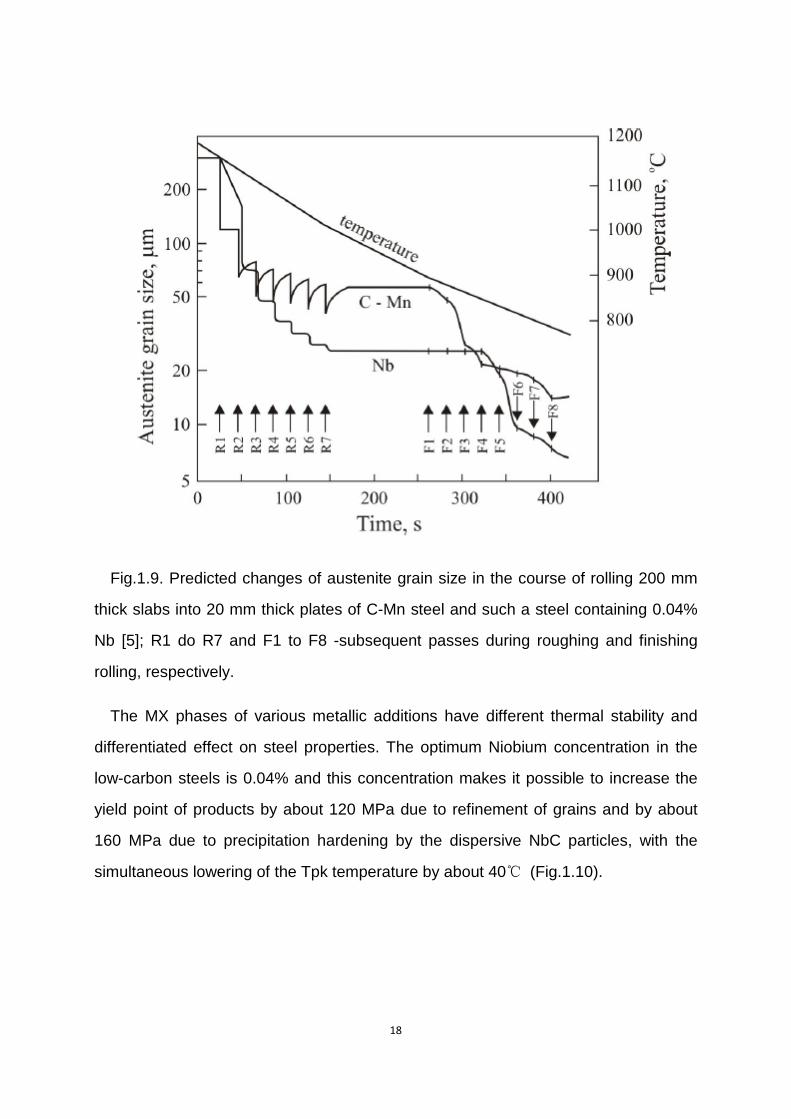
simultaneous lowering of the Tpk temperature by about 40℃ (Fig.1.10).
19
Fig.1.10 Influence of the Nb, Ti, and V content on the increase of the yield point and
variation of the impact transition temperature of the low-carbon steel[4]: GZ - influence
of grain refining, W - influence of precipitation hardening
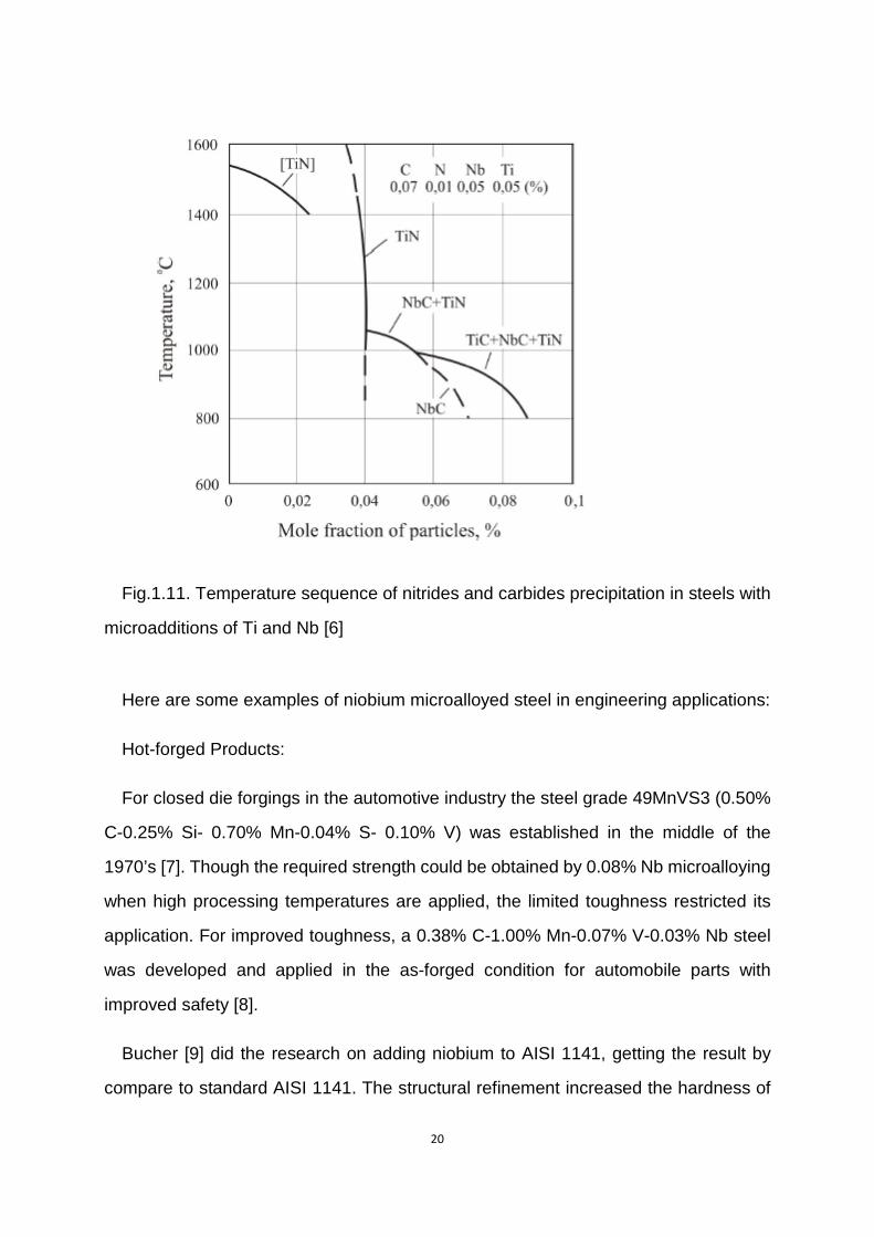
The precipitation temperature range of the MX pahses depends on concentrations
of C and N in the steel and the type of microaddition. In order to optimum use of its
metallurgical potential Niobium has to be in solid solution by an adequate reheating
furnace temperature to dissolve Nb(C,N) precipitates before hot forming. Several
additions are added into to make larger range of MX precipitation temperature
(Fig.1.11).
20
Fig.1.11. Temperature sequence of nitrides and carbides precipitation in steels with
microadditions of Ti and Nb [6]
Here are some examples of niobium microalloyed steel in engineering applications:
Hot-forged Products:
For closed die forgings in the automotive industry the steel grade 49MnVS3 (0.50%
C-0.25% Si- 0.70% Mn-0.04% S- 0.10% V) was established in the middle of the
1970’s [7]. Though the required strength could be obtained by 0.08% Nb microalloying
when high processing temperatures are applied, the limited toughness restricted its
application. For improved toughness, a 0.38% C-1.00% Mn-0.07% V-0.03% Nb steel
was developed and applied in the as-forged condition for automobile parts with
improved safety [8].
Bucher [9] did the research on adding niobium to AISI 1141, getting the result by
compare to standard AISI 1141. The structural refinement increased the hardness of
21
the niobium bearing steel to 97HRB vs. 92HRB, and improved toughness that was
sufficient for connecting rods. The niobium-modifed AISI 1141 is also used for weld
yoke or universal joint couplings.
Spring Steels:
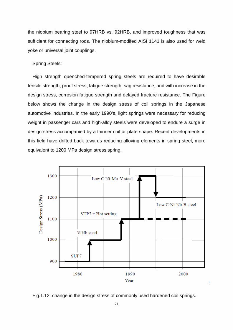
High strength quenched-tempered spring steels are required to have desirable
tensile strength, proof stress, fatigue strength, sag resistance, and with increase in the
design stress, corrosion fatigue strength and delayed fracture resistance. The Figure
below shows the change in the design stress of coil springs in the Japanese
automotive industries. In the early 1990’s, light springs were necessary for reducing
weight in passenger cars and high-alloy steels were developed to endure a surge in
design stress accompanied by a thinner coil or plate shape. Recent developments in
this field have drifted back towards reducing alloying elements in spring steel, more
equivalent to 1200 MPa design stress spring.
Fig.1.12: change in the design stress of commonly used hardened coil springs.
22
Before 1990s’, with the attempt to improve sag resistance in coil springs, by adding
V and Nb to JIS SUP7, superior sag resistance in vanadium and niobium-bearing
steel was observed, and the design stress of coil springs was raised from 900 MPa to
1000 MPa.
For saving natural resource and reduce automobile emission, as one part of auto
weight reduction program, the design stress of coil springs was successfully raised to
1330 MPa using 0.4% C-2.5% Si-0.8% Mn-2.0% Ni-0.85% Cr-0.4% Mo-0.2% V steel
with a weight-saving of over 20% being achieved. However, this development can’t go
far on the stage because of high cost of steel as Ni, Mo and V.
A new grade for 1200 MPa design stress has been developed and is gradually
increasing in commercial production. The steel composition is typically 0.4% C-1.8%
Si-0.5% Ni-1.1% Cr-0.15% V-0.025% Nb-0.0015% B. Carbon is reduced for
increasing corrosion fatigue life, Si remains at a relatively high level for sag resistance,
Ni is added to retard pitting corrosion, and Nb and B are added for grain refinement
and strengthening of the prior-austenite grain boundaries.
1.1.4.2 Vanadium and Vanadium contained microalloyed steel
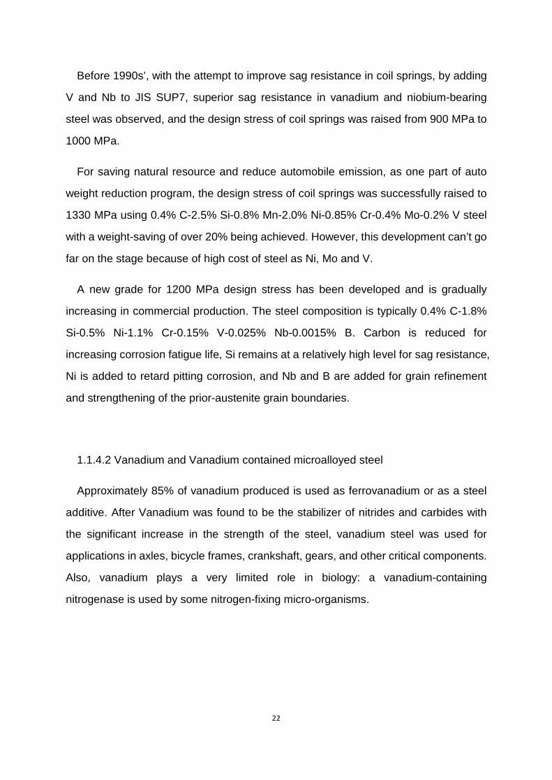
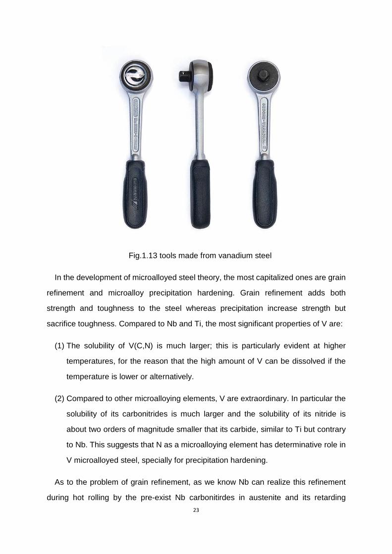
Approximately 85% of vanadium produced is used as ferrovanadium or as a steel
additive. After Vanadium was found to be the stabilizer of nitrides and carbides with
the significant increase in the strength of the steel, vanadium steel was used for
applications in axles, bicycle frames, crankshaft, gears, and other critical components.
Also, vanadium plays a very limited role in biology: a vanadium-containing
nitrogenase is used by some nitrogen-fixing micro-organisms.
23
Fig.1.13 tools made from vanadium steel
In the development of microalloyed steel theory, the most capitalized ones are grain
refinement and microalloy precipitation hardening. Grain refinement adds both
strength and toughness to the steel whereas precipitation increase strength but
sacrifice toughness. Compared to Nb and Ti, the most significant properties of V are:
(1) The solubility of V(C,N) is much larger; this is particularly evident at higher
temperatures, for the reason that the high amount of V can be dissolved if the
temperature is lower or alternatively.
(2) Compared to other microalloying elements, V are extraordinary. In particular the
solubility of its carbonitrides is much larger and the solubility of its nitride is
about two orders of magnitude smaller that its carbide, similar to Ti but contrary
to Nb. This suggests that N as a microalloying element has determinative role in
V microalloyed steel, specially for precipitation hardening.
As to the problem of grain refinement, as we know Nb can realize this refinement
during hot rolling by the pre-exist Nb carbonitirdes in austenite and its retarding
24
recrystallization process. The result is recrystallization stops and continued rolling the
unrecrystallized austenite grains makes that flattened. The main mechanism is to
increase grain boundary area of austenite.
As we mentioned before, the large solubility for V and its carbonitrides annihilate
the possibility of having effective resistance for austenite recrystallization during hot
rolling. Another new way called repeated austenite recrystallization, after each rolling
reduction and sufficient number passes, produces a very efficient austenite grain
refinement, which has a ferrite grain size as same as the former method. This method
is called Recrystallization-Controlled-Rolling (RCR).
V is one of the best elements for strong precipitation strengthening (Fig.10). The
mechanism is that larger solubility product of its carbonitrides leads to a lower solution
temperature and a larger capacity to dissolve them when increase the temperatures.
Compared to Nb carbides and nitrides, VN has much lower solubility than VC, so N
plays very important role in V-steels, especially in their precipitation strengthen.
Reviewing the literature [10], by increasing N-content, the larger driving force leads
to large nucleation rate for V(C,N) and then the hard particle—V(C,N) spacing is
realized, which results in precipitation strengthening. With this significant effect of
N-content, instead of adding strength, this effect can save alloy cost. For example,
adding N from a level of 0.005% to 0.015% makes it possible to reduce V from 0.12%
to 0.06%.
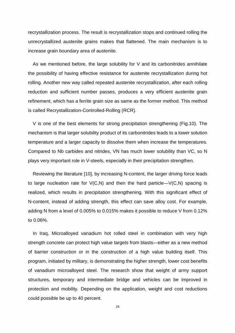
In Iraq, Microalloyed vanadium hot rolled steel in combination with very high
strength concrete can protect high value targets from blasts—either as a new method
of barrier construction or in the construction of a high value building itself. This
program, initiated by military, is demonstrating the higher strength, lower cost benefits
of vanadium microalloyed steel. The research show that weight of army support
structures, temporary and intermediate bridge and vehicles can be improved in
protection and mobility. Depending on the application, weight and cost reductions
could possible be up to 40 percent.
25
Fig.1.14. U.S. Army maintains vanadium microalloyed steel bridge designs for rapid
reconstruction during deployed operations.
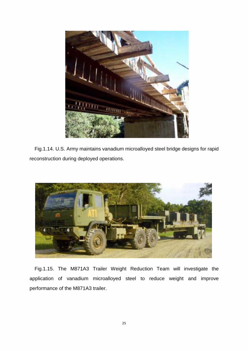
Fig.1.15. The M871A3 Trailer Weight Reduction Team will investigate the
application of vanadium microalloyed steel to reduce weight and improve
performance of the M871A3 trailer.
26
1.1.4.3 Titanium and Titanium contained microalloyed steel
Nowadays, Titanium is widely use in alloy as alloying element, to reduce grain size,
to reduce carbon content with aluminum, vanadium, copper , iron and other metals.
Due to its suitable properties, titanium alloy are widely use in aircraft, armor plating,
naval ship, spacecraft and missile. The industrial applications of titanium in welded
pipe and process equipment are mainly for its high corrosion resistance. In racing
/performance automotive market, Ti is highly preferred but it is beyond the general
consumer market. This metal is non-toxic and has no rejection by human body, then
titanium is used in a gamut of medical applications including surgical implements and
implants, such as hip balls and sockets (joint replacement) that can stay in place for
up to 20 years.
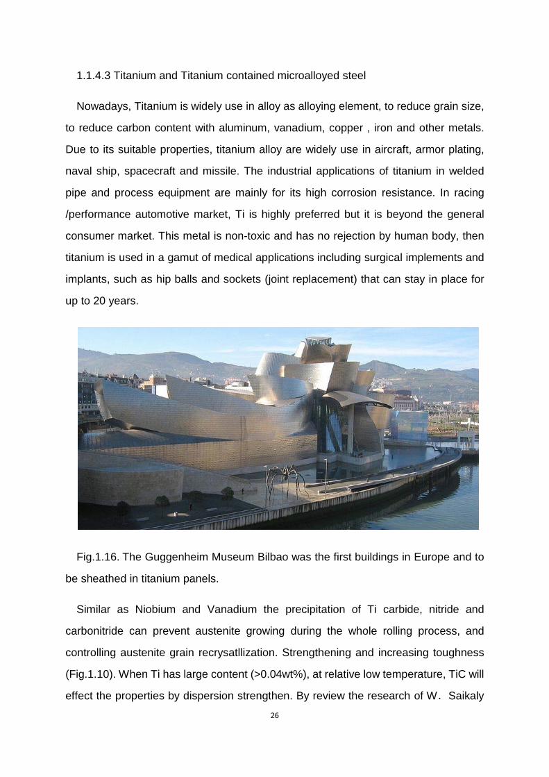
Fig.1.16. The Guggenheim Museum Bilbao was the first buildings in Europe and to
be sheathed in titanium panels.
Similar as Niobium and Vanadium the precipitation of Ti carbide, nitride and
carbonitride can prevent austenite growing during the whole rolling process, and
controlling austenite grain recrysatllization. Strengthening and increasing toughness
(Fig.1.10). When Ti has large content (>0.04wt%), at relative low temperature, TiC will
effect the properties by dispersion strengthen. By review the research of W.Saikaly
27
[11] on contribution of TiC to the yield strength,specimen with (wt%) 0.085C、0.96Mn、
0.23Si、0.004S、0.0065N、0.045—0.13Ti,under suitable process method can
increase the yield strength by 100-250 MPa.
The appearance of Ti in sulfur contained microalloyed steel can produce compound
Ti4C2S2, at the same time eliminate MnS products. This result highly reduces the
properties difference within length and breadth, improving cold deformation property.
When adding other microaddition like Nb and V, small amount of Ti can produce
TiN easily, occupying major free N and increasing solubility of other microaddition.
Then, during cooling process, other element will precipitate small carbonitrides
particle to harden the steel. Meanwhile, nitrogen content decreasing result in less
Nb(C,N) precipitate on grain boundary, and this change largely improve the hot
ductility of Nb alloy, reducing hot cracking during hot work.
1.2 Hot Ductility
Microalloyed steel, with high yield strength, good toughness and fine grain structure,
has application preference in many fields. But during hot processing, at certain high
temperature region (usually 700-1000℃), microalloyed steel is very sensible to
cracking and may fracture during deformation. There is a considerable loss in ductility
which leads to fracture. To measure this loss, hot ductility tensile test is introduced. As
one important result after fracture the specimen, the reduction of area values (R of A)
are taken as a measure of the ductility and the value required to prevent cracking
occurring is dependent on the exact test conditions. To make sure the steel do not
experience a sudden failure, the reduction of area should be above 40%.
1.2.1 Variations influence the hot ductility
Reviewing the work by Mintz, the poor ductility in the trough is always related to
intergranular failure at the γ grain boundaries [12]. Cracks are formed along these

28
boundaries, and grain boundary sliding in the austenite and transformation controlled
intergranular failure are the two mechanisms leading to cracks. The first mechanism is
stongly encouraged by having particles at the boundaries and the presence of a fine
matrix precipitation, for instance Nb microalloyed steel, accompanied by precipitate
free zones, will enhance this mechanism. For the latter mechanism thin films of ferrite
growing surrounding the γ grain boundaries may lead to transformation controlled
intergranular failure.
Four important variables control ductility: strain rate, grain size, precipitation and
inclusion content (their size, volume fraction and distribution being important) [13].
Increasing the strain can reduce the amount of grain boundary sliding, and refining the
grain size can make it more difficult for cracks to propagate along the boundaries.
Both of the above methods give rise to improved ductility. But it’s not generally
possible to alter either of these sufficiently in conventional continuous casting to make
significant improve to ductility.
As to precipitation, finer precipitation leads to worse ductility. Grain boundary
precipitation is particularly detrimental. Within a particular volume fraction of
precipitate or inclusions, finer particles at boundaries make them closer to each other,
thus cracks may interlink. Strain induced precipitation is always finer, hence more
harmful to ductility than precipitation present before strain [13].
As the important possible content of microalloyed steel, Niobium, Vanadium,
Titanium and other microadditions play significant role in improve the mechanical
properties of steel, but on the contrary, their exist in high temperature region is not
always welcome, for there effects to the hot ductility.
1.2.1.1 Influence of niobium and vanadium to hot ductility
Niobium, the most common microaddtion in microalloying, precipitates in the form
of Nb carbonitrides, which is particularly effective in reducing the hot ductility and
widening the trough in hot ductility curve.
29
For Nb containing steels, intergranular failure in the higher temperature range
(900℃) invariably occurs by grain boundary sliding in the austenite. The fine matrix
precipitation of Nb(C,N) increases the stress required for deformation and therefore,
increases the stress in grain boundary regions. Then precipitate free zones usually
appear at the boundaries, concentrating the strain in there. Furthermore, there is
always marked precipitation at the austenite grain boundaries and this will facilitate
voiding and elongation of cracks formed by grain boundary sliding. If the precipitation
is fine with close spacing of particle as what in Nb containing steels, cracks can
readily link up.
At lower temperature (800 ℃ ), deformation induced ferrite, together with
precipitation, leads to continued poor ductility. Nevertheless, fracture is by microvoid
coalescence at the MnS inclusions present in these thin films and Nb(C,N)
precipitations make the situation worse.
The improvement in ductility can be realized by increasing the temperature above
Ae3 to eliminate deformation induced ferrite, but this improvement is small, since
grain boundary sliding in the austenite then occurs, which is deleterious to ductility. In
the end, the main improvement in ductility is associated with dynamic recrystallizaiton.
For Nb containing steels, the fine precipitation of Nb(C,N) formed on deformation
delays the onset of dynamic recrystallization to higher temperatures, thus widen the
trough to higher temperatures. The presence of abundant volume fraction of ferrite
leads to ductility recovery at low temperature end of the trough. Also, the strength
variation between the γ and ferrite is reduced [14].
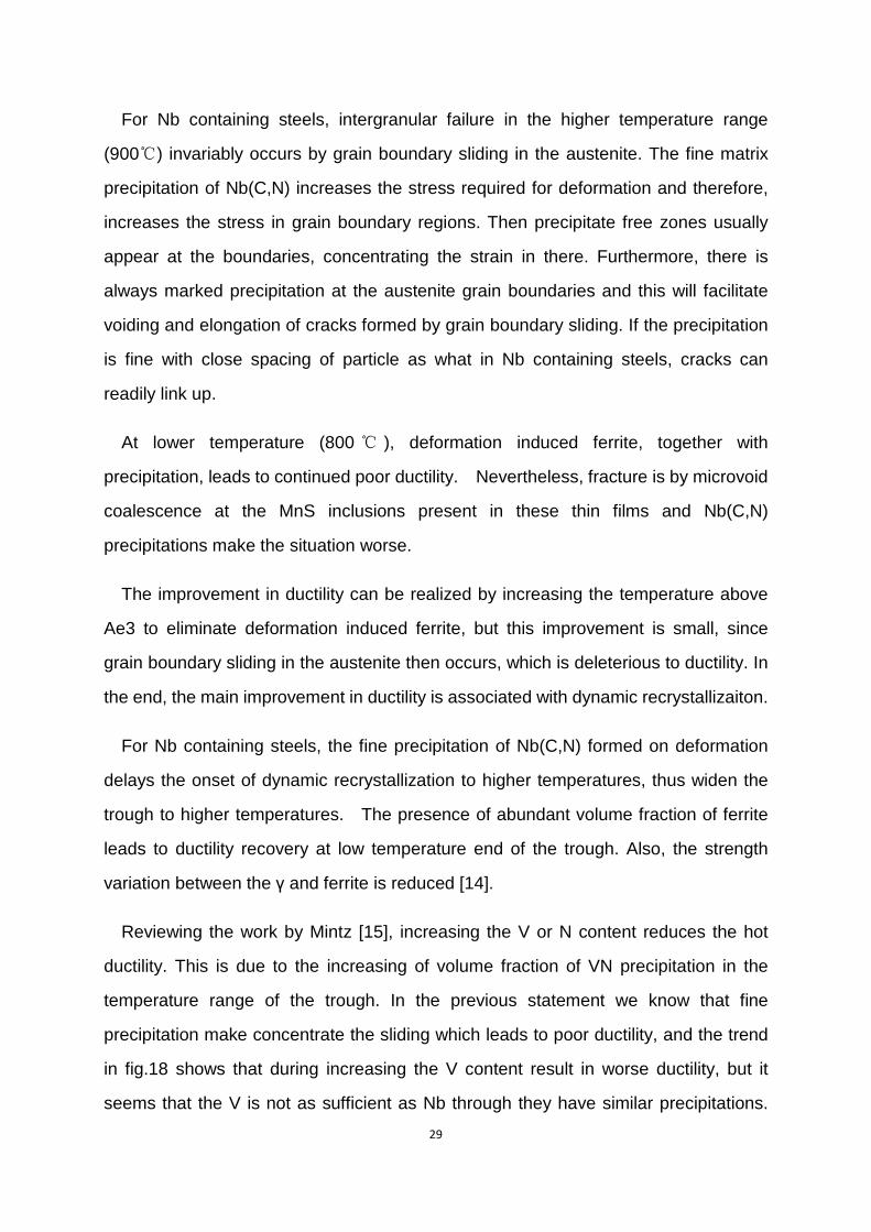
Reviewing the work by Mintz [15], increasing the V or N content reduces the hot
ductility. This is due to the increasing of volume fraction of VN precipitation in the
temperature range of the trough. In the previous statement we know that fine
precipitation make concentrate the sliding which leads to poor ductility, and the trend
in fig.18 shows that during increasing the V content result in worse ductility, but it
seems that the V is not as sufficient as Nb through they have similar precipitations.
30
this is probably because at these V and N contents, precipitation is less extensive but
coarser than that shown but the Nb containing. Similar as Nb, recovery of ductility at
higher temperature end of the trough is related to dynamic recrystallization, which will
be encouraged if the precipitation becomes more intense.
V has higher solubility in austenite than Nb does, so precipitates would also be
expected to coarsen more rapidly in V containing steel according the Lifshitz-Wanger
theory of particle coarsening. This is the reasonable explanation for V having less
effects than Nb in reducing hot ductility, because during solidification of continuously
cast strand, it forms a coarser precipitate and therefore much more are required for
ductility deteriorates. Through coarser than Nb(C,N), V rich precipitates are
sufficiently fine enough for strengthening in solution during reheating for rolling.
31
Fig .1.17 hot ductility cure of the above steels examined [15]
1.2.1.2 Influence of Titanium on hot ductility
Work by Abushosha [16] shows that the ductility of Ti containing Nb free steels is
dependent on the cooling rate, particle size, and volume fraction. The increasing of
cooling rate leads to refinement of sulphides at the boundaries, hence cracks can
easily join up to structural failure. Similar to Nb, fine precipitation particles is
detrimental to ductility by strengthening the austenite, linking up cracks as inclusions
do.
Increasing particle size has the effect on improving hot ductility [16]. But particle
size is also influenced by the Ti/N ratio, the product of [Ti]*[N], cooling rate and test
temperature. Coarser particle will be formed if Ti/N ratio is above 3.4:1, thus the larger
32
amount of Ti in solution will favor the growth of Ti containing particles. The product of
[Ti]*[N] is the symbol for volume fraction, where it increases, the hot ductility reduces.
For Nb containing steels, the addition of Ti generally give poor ductility [17], for Ti
containing precipitation being very fine and stable at high temperatures. However, in
industry application, Ti has good effect in improving the surface quality of continuously
cast slabs. From the hypothesis and demonstration by Comineli [17], it appears that
for limiting the volume fraction of Ti nitride, lower Ti levels is recommended to get hot
ductility. Or else, the cooperation of low N level for limiting the volume fraction and
high Ti level for favoring growth will give good ductility.
If N level is high, a low Ti level is inclined to limit volume fraction of Ti containing
precipitate. It’s possible that having a high N level at the same time a high [Ti]*[N]
product will encourage precipitation at higher temperatures, getting coarser
precipitation.
1.2.1.3 influence of aluminum on hot ductility
Aluminium is not usually classified as a microalloying element. The precipitation of
AlN can, however have strong influence on the properties of microalloyed steel, as Nb,
V or Ti does. At higher temperature aluminium dissolve in austenite before rolling but
AlN is stable at lower temperatures. In Titanium and niobium containing steel,
Comineli [17] found that raising the soluble Al level did not influence the ductility.
Nevertheless average particle size is coarser in the higher Al containing steel. Loberg
et al.[18] have suggested that when Al associates with N, though no precipitate
produced, the amount of Ti in solution increases, encouraging growth. Furthermore,
work by Mintz [12] found that Nb suppresses the precipitation.
1.2.2 Hot ductility during continuous casting
In previous statement, microalloyed steel show their excellent properties in
strengthening and grain refinement, but within some special high temperature range,
33
it always shows their fragile and breakage during continuous casting. Continuous cast
microalloyed steel has the coarse melting structure.
Molten metal achieving the right temperature after the ladle treatment and vacuum
degassing is casted with the continuous casting method in the argon temperature,
protecting the steel from the secondary oxidation and nitriding. The ladle with the
molten metal is transported to the continuous casting system consisting of the tundish
maintaining the continuous metallostatic pressure. Copper mould allows cooling water
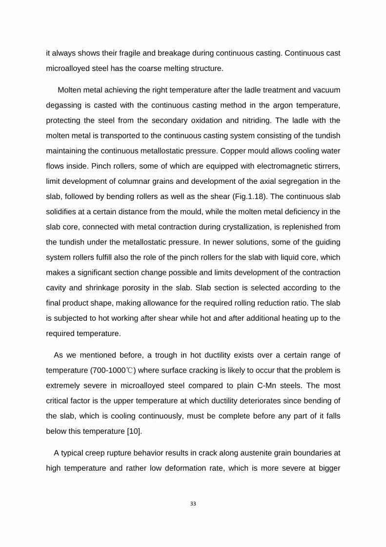
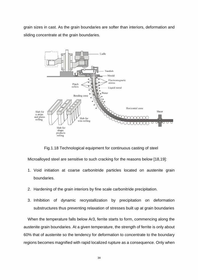
flows inside. Pinch rollers, some of which are equipped with electromagnetic stirrers,
limit development of columnar grains and development of the axial segregation in the
slab, followed by bending rollers as well as the shear (Fig.1.18). The continuous slab
solidifies at a certain distance from the mould, while the molten metal deficiency in the
slab core, connected with metal contraction during crystallization, is replenished from
the tundish under the metallostatic pressure. In newer solutions, some of the guiding
system rollers fulfill also the role of the pinch rollers for the slab with liquid core, which
makes a significant section change possible and limits development of the contraction
cavity and shrinkage porosity in the slab. Slab section is selected according to the
final product shape, making allowance for the required rolling reduction ratio. The slab
is subjected to hot working after shear while hot and after additional heating up to the
required temperature.
As we mentioned before, a trough in hot ductility exists over a certain range of
temperature (700-1000℃) where surface cracking is likely to occur that the problem is
extremely severe in microalloyed steel compared to plain C-Mn steels. The most
critical factor is the upper temperature at which ductility deteriorates since bending of
the slab, which is cooling continuously, must be complete before any part of it falls
below this temperature [10].
A typical creep rupture behavior results in crack along austenite grain boundaries at
high temperature and rather low deformation rate, which is more severe at bigger
34
grain sizes in cast. As the grain boundaries are softer than interiors, deformation and
sliding concentrate at the grain boundaries.
Fig.1.18 Technological equipment for continuous casting of steel
Microalloyed steel are sensitive to such cracking for the reasons below [18,19]:
1. Void initiation at coarse carbonitride particles located on austenite grain
boundaries.
2. Hardening of the grain interiors by fine scale carbonitride precipitation.
3. Inhibition of dynamic recrystallization by precipitation on deformation
substructures thus preventing relaxation of stresses built up at grain boundaries
When the temperature falls below Ar3, ferrite starts to form, commencing along the
austenite grain boundaries. At a given temperature, the strength of ferrite is only about
60% that of austenite so the tendency for deformation to concentrate to the boundary
regions becomes magnified with rapid localized rupture as a consequence. Only when
35
the structure becomes mainly ferritic at lower temperatures, the deformation becomes
more uniformly and ductility is restored.
1.3 Research Purpose
In the previous section, influence of Nb, V, Ti and other microalloying element has
been reviewed, similarly there effect mainly originate from the concentration of sliding
and deformation, particle size and morphology( fine or coarse), concentration level to
affect solubility and so on, even though, full agreement concerning the mechanism of
hot ductility loss still seems to be lack. However, to any specific problem, we have a
perfect frame of experimental method and sufficient relative knowledge to figure it out.
A lot of literatures [13,14,15,16] have been done on the hot ductility loss of as cast
steel, however, about the influence of microaddition on hot ductility of rolled steel,
there are really few references to consult. Our aim is to find the hot ductility
performance of rolled microalloyed steel, with respect to that of as cast steel. As to the
possible great improvement or reduction in hot ductility, optical analysis is necessary
to find out the influence aspect for fracture and which factors are the key leading to
these properties changes.
36
Chapter 2 Experimental procedure and result analysis
2.1 Microalloyed Steels Rolled and as cast structure of type D and type F
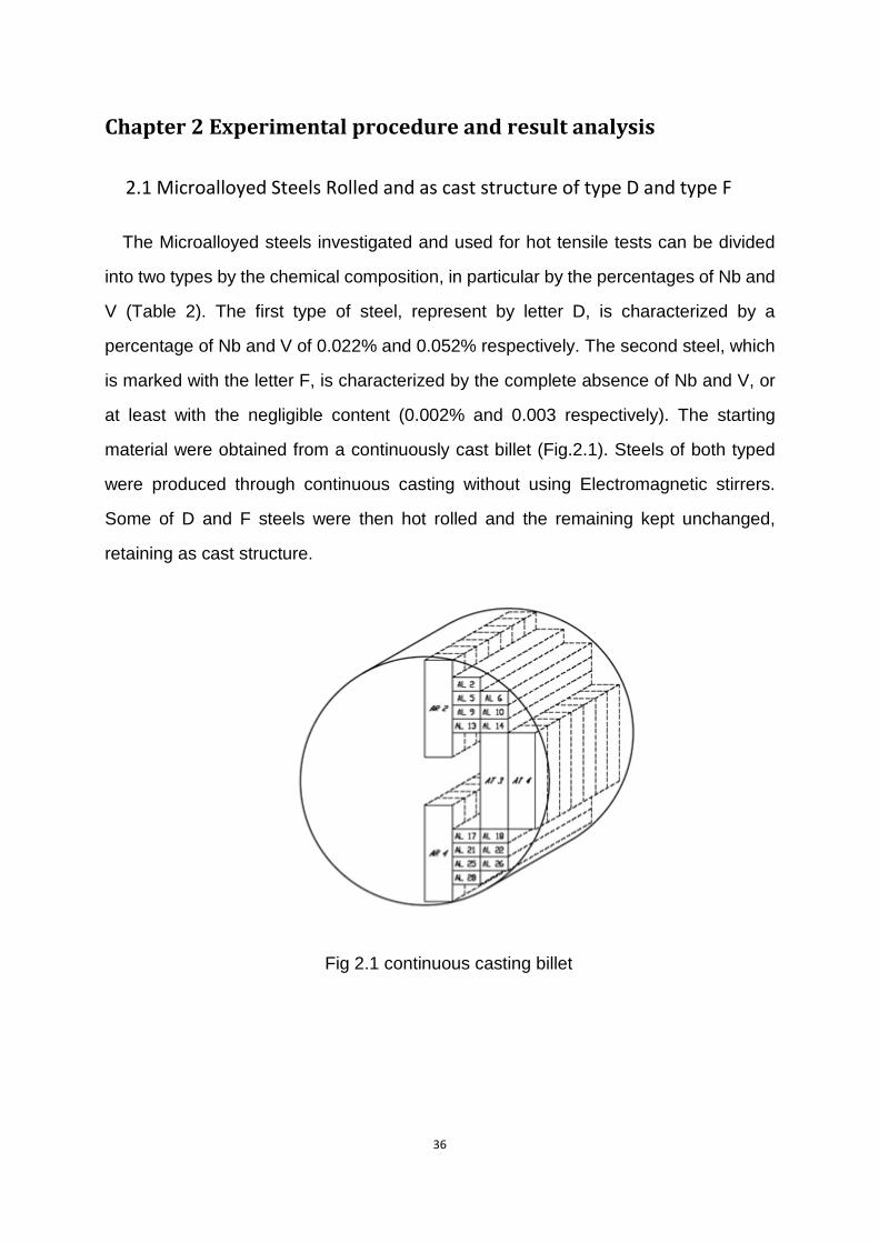
The Microalloyed steels investigated and used for hot tensile tests can be divided
into two types by the chemical composition, in particular by the percentages of Nb and
V (Table 2). The first type of steel, represent by letter D, is characterized by a
percentage of Nb and V of 0.022% and 0.052% respectively. The second steel, which
is marked with the letter F, is characterized by the complete absence of Nb and V, or
at least with the negligible content (0.002% and 0.003 respectively). The starting
material were obtained from a continuously cast billet (Fig.2.1). Steels of both typed
were produced through continuous casting without using Electromagnetic stirrers.
Some of D and F steels were then hot rolled and the remaining kept unchanged,
retaining as cast structure.
Fig 2.1 continuous casting billet
37
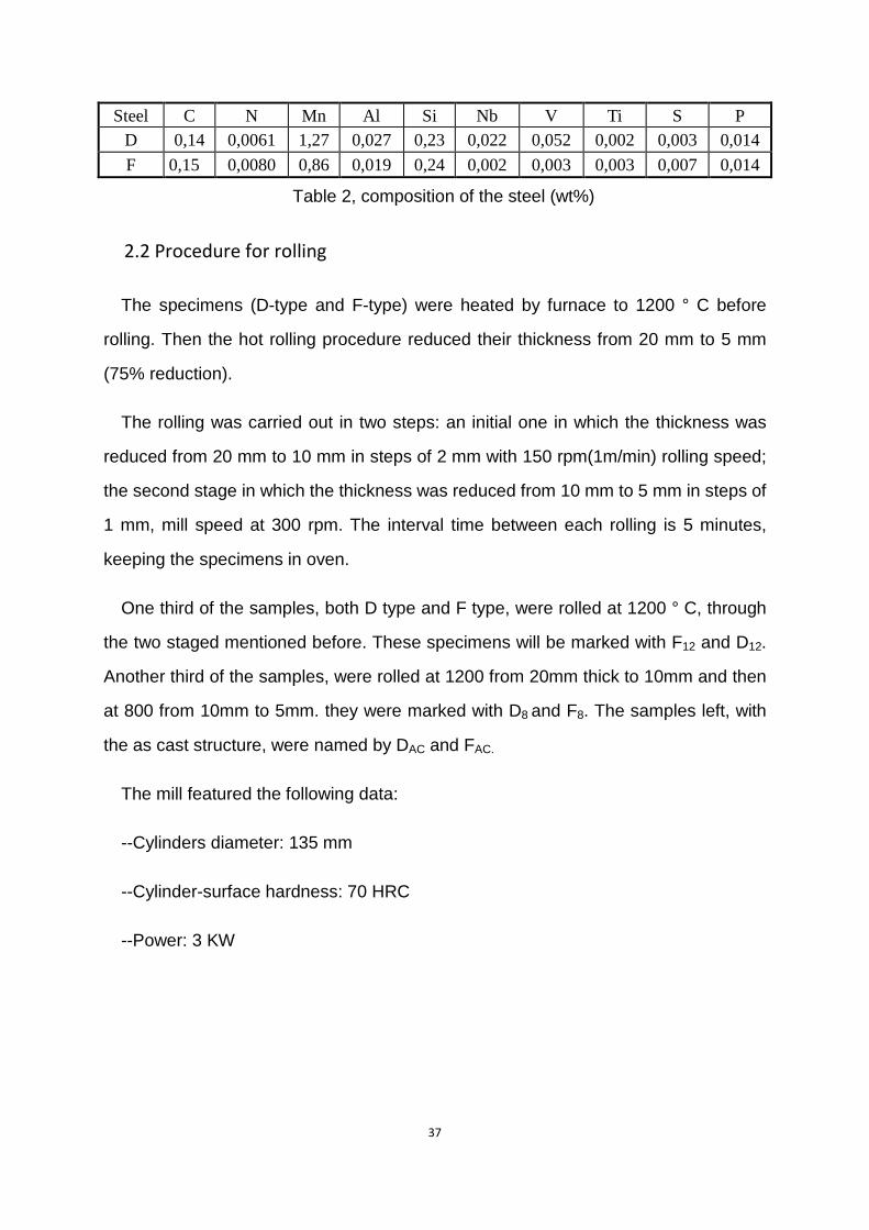
Steel C N Mn Al Si Nb V Ti S P D 0,14 0,0061 1,27 0,027 0,23 0,022 0,052 0,002 0,003 0,014 F 0,15 0,0080 0,86 0,019 0,24 0,002 0,003 0,003 0,007 0,014
Table 2, composition of the steel (wt%)
2.2 Procedure for rolling
The specimens (D-type and F-type) were heated by furnace to 1200 ° C before
rolling. Then the hot rolling procedure reduced their thickness from 20 mm to 5 mm
(75% reduction).
The rolling was carried out in two steps: an initial one in which the thickness was
reduced from 20 mm to 10 mm in steps of 2 mm with 150 rpm(1m/min) rolling speed;
the second stage in which the thickness was reduced from 10 mm to 5 mm in steps of
1 mm, mill speed at 300 rpm. The interval time between each rolling is 5 minutes,
keeping the specimens in oven.
One third of the samples, both D type and F type, were rolled at 1200 ° C, through
the two staged mentioned before. These specimens will be marked with F12 and D12.
Another third of the samples, were rolled at 1200 from 20mm thick to 10mm and then
at 800 from 10mm to 5mm. they were marked with D8 and F8. The samples left, with
the as cast structure, were named by DAC and FAC.
The mill featured the following data:
--Cylinders diameter: 135 mm
--Cylinder-surface hardness: 70 HRC
--Power: 3 KW
38
(a)
(b)
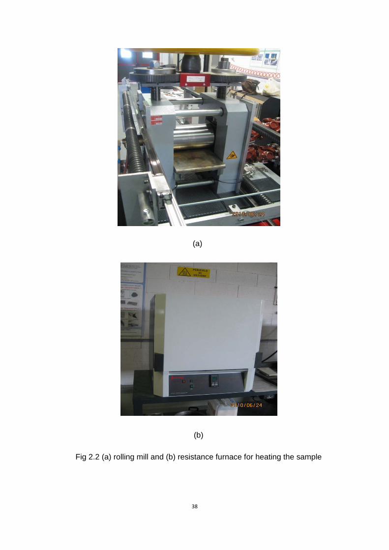
Fig 2.2 (a) rolling mill and (b) resistance furnace for heating the sample
39
2.3 Sample preparation
Expose the specimens in air for cooling, and take some small pieces of the material
(1 cm3) for making samples.
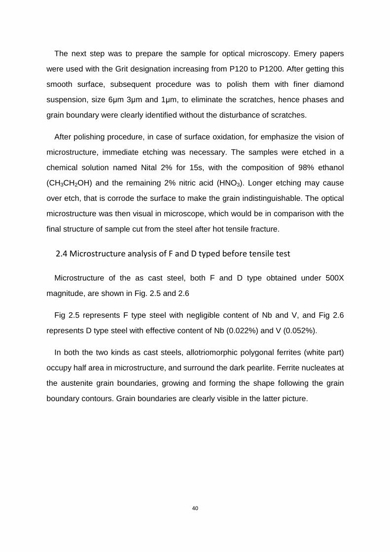
The pieces were taken by cutting along the rolling direction (RD), and the extraction
corner is shown in Figure 2.4. Later this small sample was put into the mounting
machine, squeezed with thermosetting resin under a thermal cycle consisting a
heating (up to 175 ° C), and then, it was maintained isothermal (6 minutes), cooled
subsequently.
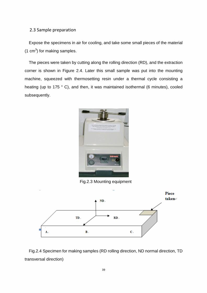
Fig.2.3 Mounting equipment
Fig.2.4 Specimen for making samples (RD rolling direction, ND normal direction, TD
transversal direction)
40
The next step was to prepare the sample for optical microscopy. Emery papers
were used with the Grit designation increasing from P120 to P1200. After getting this
smooth surface, subsequent procedure was to polish them with finer diamond
suspension, size 6μm 3μm and 1μm, to eliminate the scratches, hence phases and
grain boundary were clearly identified without the disturbance of scratches.
After polishing procedure, in case of surface oxidation, for emphasize the vision of
microstructure, immediate etching was necessary. The samples were etched in a
chemical solution named Nital 2% for 15s, with the composition of 98% ethanol
(CH3CH2OH) and the remaining 2% nitric acid (HNO3). Longer etching may cause
over etch, that is corrode the surface to make the grain indistinguishable. The optical
microstructure was then visual in microscope, which would be in comparison with the
final structure of sample cut from the steel after hot tensile fracture.
2.4 Microstructure analysis of F and D typed before tensile test
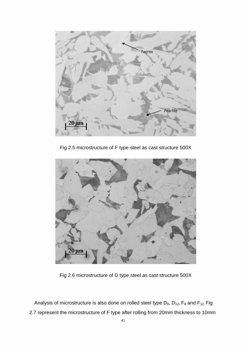
Microstructure of the as cast steel, both F and D type obtained under 500X
magnitude, are shown in Fig. 2.5 and 2.6
Fig 2.5 represents F type steel with negligible content of Nb and V, and Fig 2.6
represents D type steel with effective content of Nb (0.022%) and V (0.052%).
In both the two kinds as cast steels, allotriomorphic polygonal ferrites (white part)
occupy half area in microstructure, and surround the dark pearlite. Ferrite nucleates at
the austenite grain boundaries, growing and forming the shape following the grain
boundary contours. Grain boundaries are clearly visible in the latter picture.
41
Fig 2.5 microstructure of F type steel as cast structure 500X
Fig 2.6 microstructure of D type steel as cast structure 500X
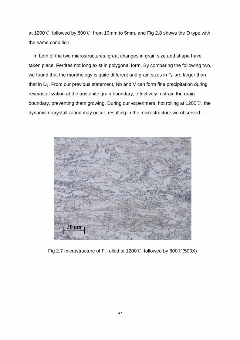
Analysis of microstructure is also done on rolled steel type D8, D12, F8 and F12. Fig
2.7 represent the microstructure of F type after rolling from 20mm thickness to 10mm
Pearlite
Ferrite
42
at 1200℃ followed by 800℃ from 10mm to 5mm, and Fig 2.8 shows the D type with
the same condition.
In both of the two microstructures, great changes in grain size and shape have
taken place. Ferrites not long exist in polygonal form. By comparing the following two,
we found that the morphology is quite different and grain sizes in F8 are larger than
that in D8. From our previous statement, Nb and V can form fine precipitation during
reycrastallization at the austenite grain boundary, effectively restrain the grain
boundary, preventing them growing. During our experiment, hot rolling at 1200℃, the
dynamic recrystallization may occur, resulting in the microstructure we observed. .
Fig 2.7 microstructure of F8 rolled at 1200℃ followed by 800℃(500X)
43
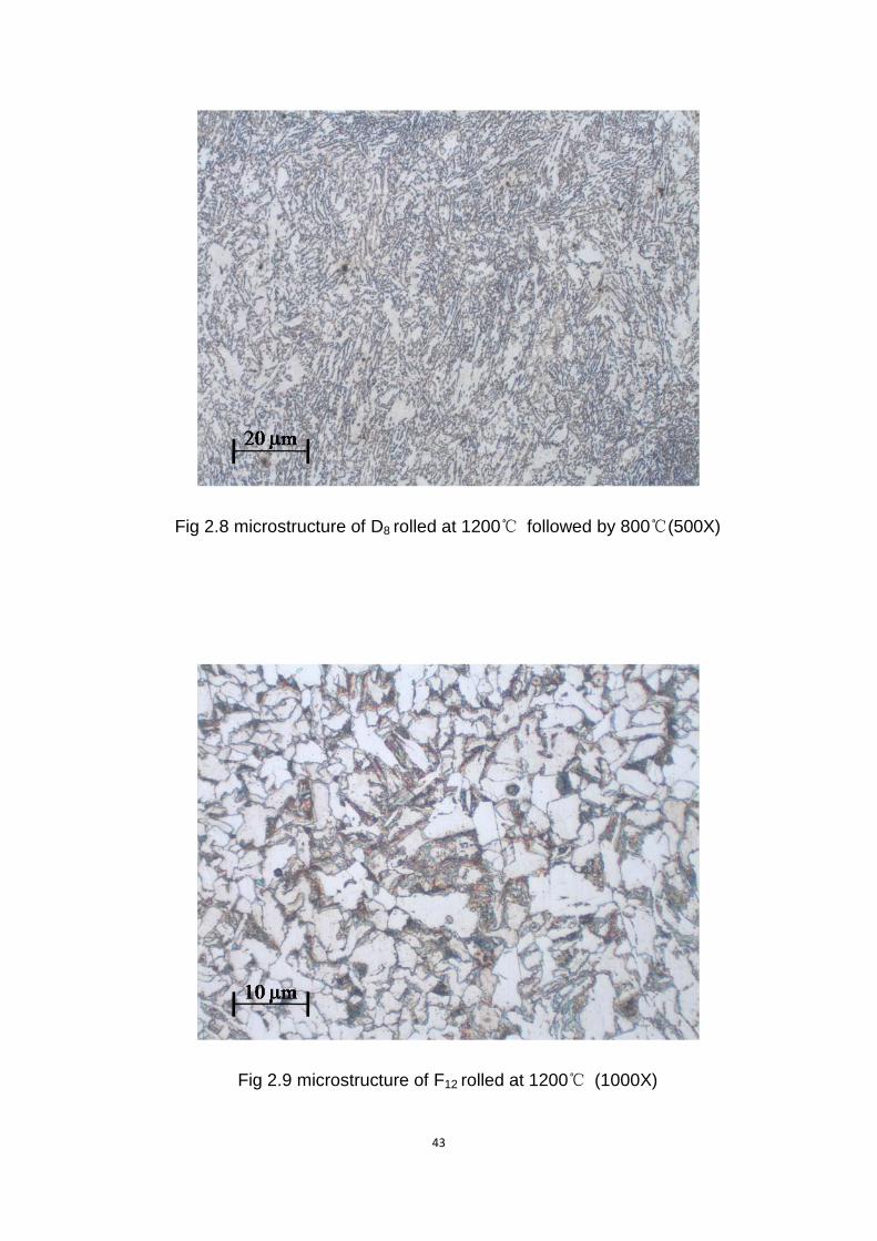
Fig 2.8 microstructure of D8 rolled at 1200℃ followed by 800℃(500X)
Fig 2.9 microstructure of F12 rolled at 1200℃ (1000X)
44
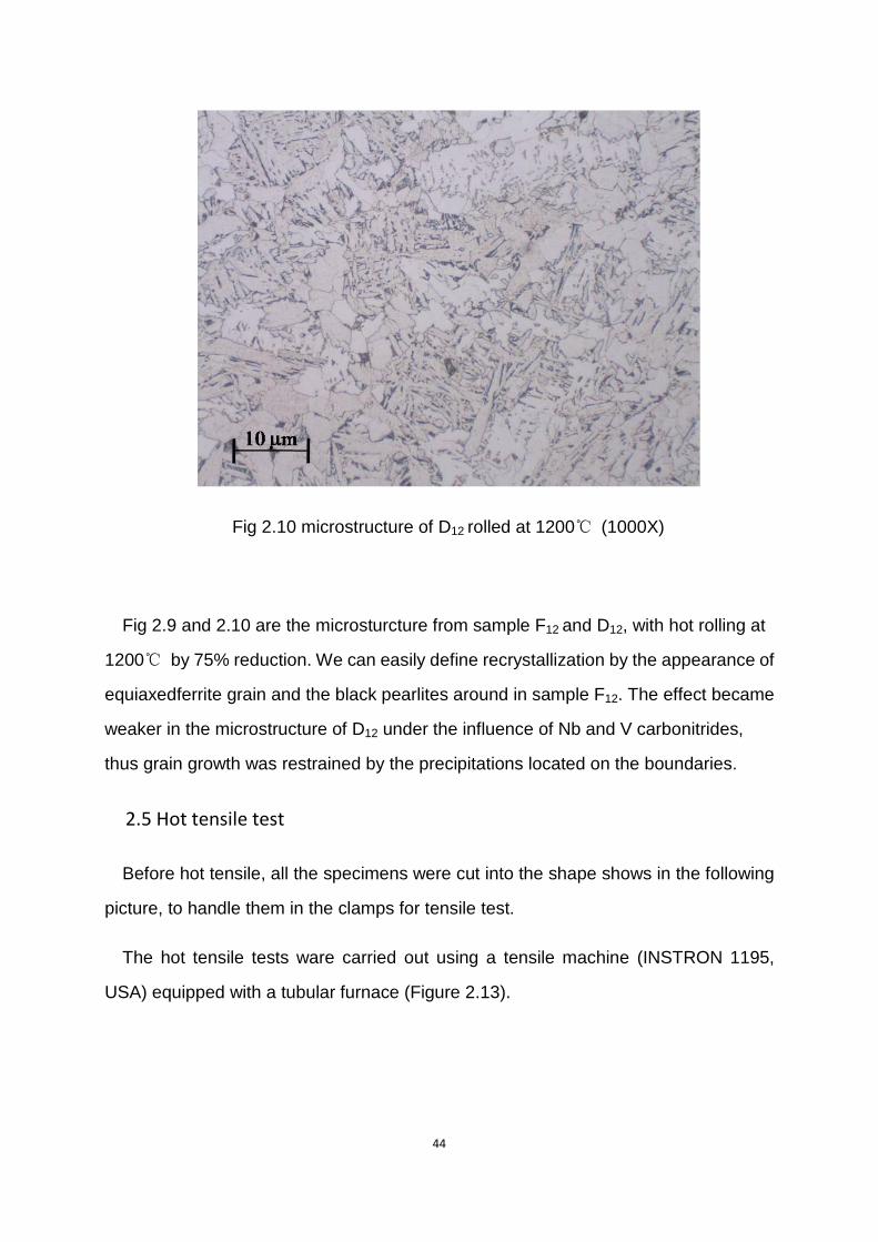
Fig 2.10 microstructure of D12 rolled at 1200℃ (1000X)
Fig 2.9 and 2.10 are the microsturcture from sample F12 and D12, with hot rolling at
1200℃ by 75% reduction. We can easily define recrystallization by the appearance of
equiaxedferrite grain and the black pearlites around in sample F12. The effect became
weaker in the microstructure of D12 under the influence of Nb and V carbonitrides,
thus grain growth was restrained by the precipitations located on the boundaries.
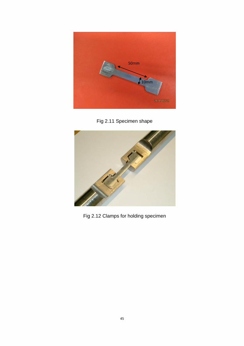
2.5 Hot tensile test
Before hot tensile, all the specimens were cut into the shape shows in the following
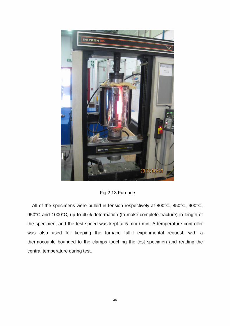
picture, to handle them in the clamps for tensile test.
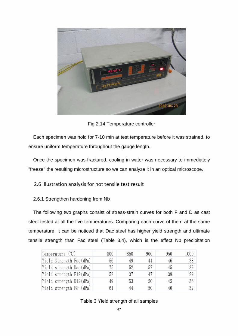
The hot tensile tests ware carried out using a tensile machine (INSTRON 1195,
USA) equipped with a tubular furnace (Figure 2.13).
45
Fig 2.11 Specimen shape
Fig 2.12 Clamps for holding specimen
50mm
10mm
46
Fig 2.13 Furnace
All of the specimens were pulled in tension respectively at 800°C, 850°C, 900°C,
950°C and 1000°C, up to 40% deformation (to make complete fracture) in length of
the specimen, and the test speed was kept at 5 mm / min. A temperature controller
was also used for keeping the furnace fulfill experimental request, with a
thermocouple bounded to the clamps touching the test specimen and reading the
central temperature during test.
47
Fig 2.14 Temperature controller
Each specimen was hold for 7-10 min at test temperature before it was strained, to
ensure uniform temperature throughout the gauge length.
Once the specimen was fractured, cooling in water was necessary to immediately
"freeze" the resulting microstructure so we can analyze it in an optical microscope.
2.6 Illustration analysis for hot tensile test result
2.6.1 Strengthen hardening from Nb
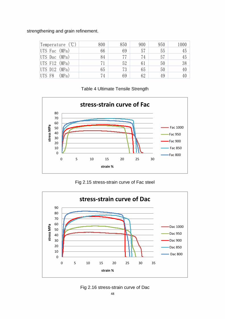
The following two graphs consist of stress-strain curves for both F and D as cast
steel tested at all the five temperatures. Comparing each curve of them at the same
temperature, it can be noticed that Dac steel has higher yield strength and ultimate
tensile strength than Fac steel (Table 3,4), which is the effect Nb precipitation
Temperature (℃) 800 850 900 950 1000Yield Strength Fac(MPa) 56 49 44 46 38Yield strength Dac(MPa) 75 52 57 45 39Yield strength F12(MPa) 52 37 47 39 29Yield strength D12(MPa) 49 53 50 45 36Yield strength F8 (MPa) 61 44 50 40 32
Table 3 Yield strength of all samples
48
strengthening and grain refinement.
Temperature (℃) 800 850 900 950 1000UTS Fac (MPa) 66 69 57 55 45UTS Dac (MPa) 84 77 74 57 45UTS F12 (MPa) 71 52 61 50 38UTS D12 (MPa) 65 73 65 50 40UTS F8 (MPa) 74 69 62 49 40
Table 4 Ultimate Tensile Strength
Fig 2.15 stress-strain curve of Fac steel
Fig 2.16 stress-strain curve of Dac
01020304050607080
0 5 10 15 20 25 30
stre
ss M
Pa
strain %
stress-strain curve of Fac
Fac 1000
Fac 950
Fac 900
Fac 850
Fac 800
0
10
20
30
40
50
60
70
80
90
0 5 10 15 20 25 30 35
stre
ss M
Pa
strain %
stress-strain curve of Dac
Dac 1000
Dac 950
Dac 900
Dac 850
Dac 800
49
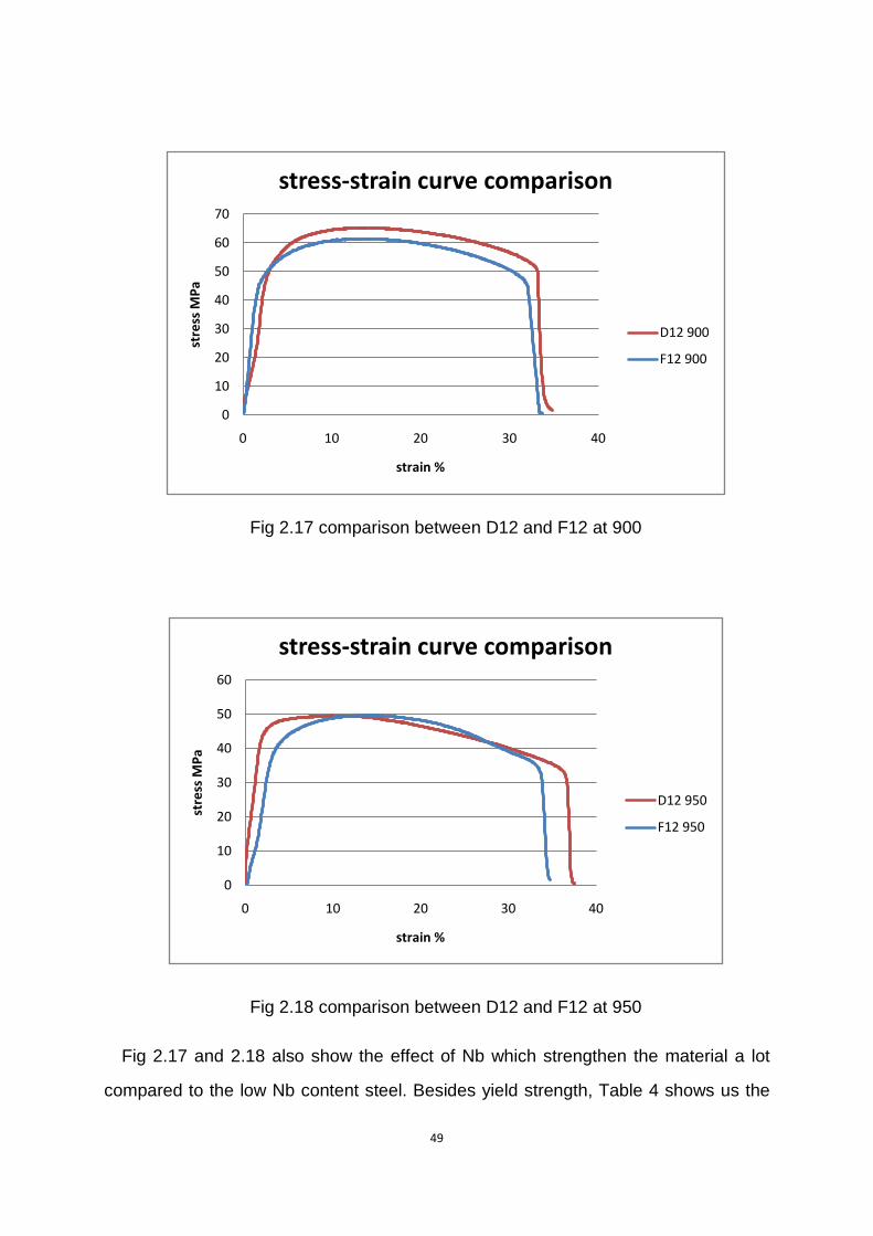
Fig 2.17 comparison between D12 and F12 at 900
Fig 2.18 comparison between D12 and F12 at 950
Fig 2.17 and 2.18 also show the effect of Nb which strengthen the material a lot
compared to the low Nb content steel. Besides yield strength, Table 4 shows us the
0
10
20
30
40
50
60
70
0 10 20 30 40
stre
ss M
Pa
strain %
stress-strain curve comparison
D12 900
F12 900
0
10
20
30
40
50
60
0 10 20 30 40
stre
ss M
Pa
strain %
stress-strain curve comparison
D12 950
F12 950
50
data of Ultimate Tensile Strength of different samples at the all test temperature. Most
of D typed steels have great enhance in this aspect, proving the excellent hardening
effects of Nb and V in steel.
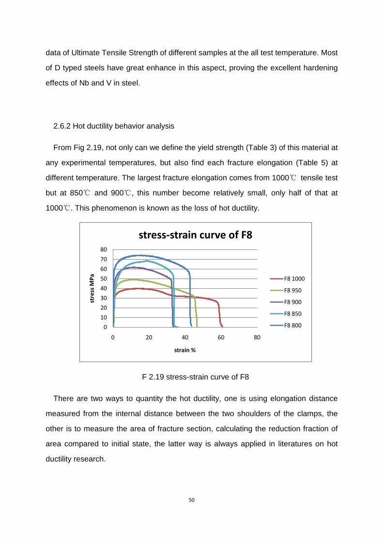
2.6.2 Hot ductility behavior analysis
From Fig 2.19, not only can we define the yield strength (Table 3) of this material at
any experimental temperatures, but also find each fracture elongation (Table 5) at
different temperature. The largest fracture elongation comes from 1000℃ tensile test
but at 850℃ and 900℃, this number become relatively small, only half of that at
1000℃. This phenomenon is known as the loss of hot ductility.
F 2.19 stress-strain curve of F8
There are two ways to quantity the hot ductility, one is using elongation distance
measured from the internal distance between the two shoulders of the clamps, the
other is to measure the area of fracture section, calculating the reduction fraction of
area compared to initial state, the latter way is always applied in literatures on hot
ductility research.
0
10
20
30
40
50
60
70
80
0 20 40 60 80
stre
ss M
Pa
strain %
stress-strain curve of F8
F8 1000
F8 950
F8 900
F8 850
F8 800
51
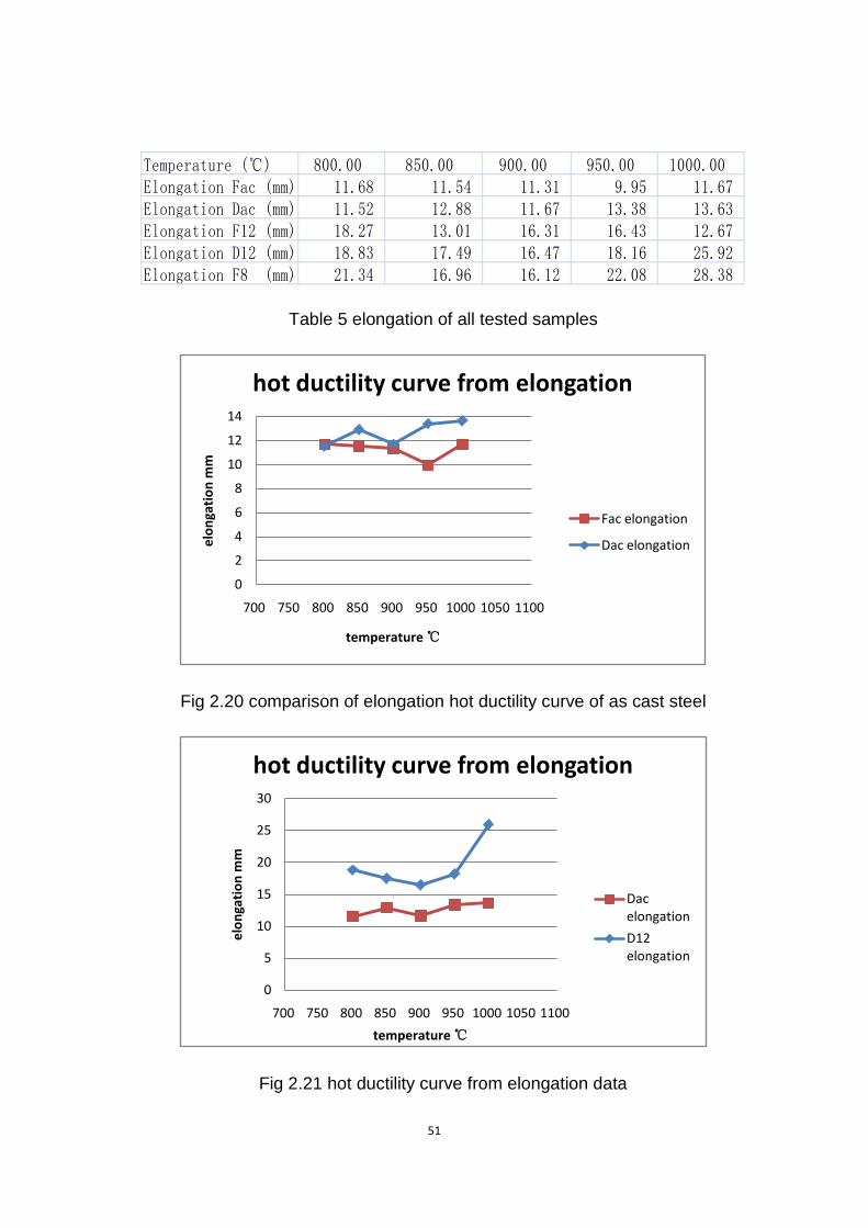
Temperature (℃) 800.00 850.00 900.00 950.00 1000.00Elongation Fac (mm) 11.68 11.54 11.31 9.95 11.67Elongation Dac (mm) 11.52 12.88 11.67 13.38 13.63Elongation F12 (mm) 18.27 13.01 16.31 16.43 12.67Elongation D12 (mm) 18.83 17.49 16.47 18.16 25.92Elongation F8 (mm) 21.34 16.96 16.12 22.08 28.38
Table 5 elongation of all tested samples
Fig 2.20 comparison of elongation hot ductility curve of as cast steel
Fig 2.21 hot ductility curve from elongation data
0
2
4
6
8
10
12
14
700 750 800 850 900 950 1000 1050 1100
elon
gati
on m
m
temperature ℃
hot ductility curve from elongation
Fac elongation
Dac elongation
0
5
10
15
20
25
30
700 750 800 850 900 950 1000 1050 1100
elon
gati
on m
m
temperature ℃
hot ductility curve from elongation
Dac elongation
D12 elongation
52
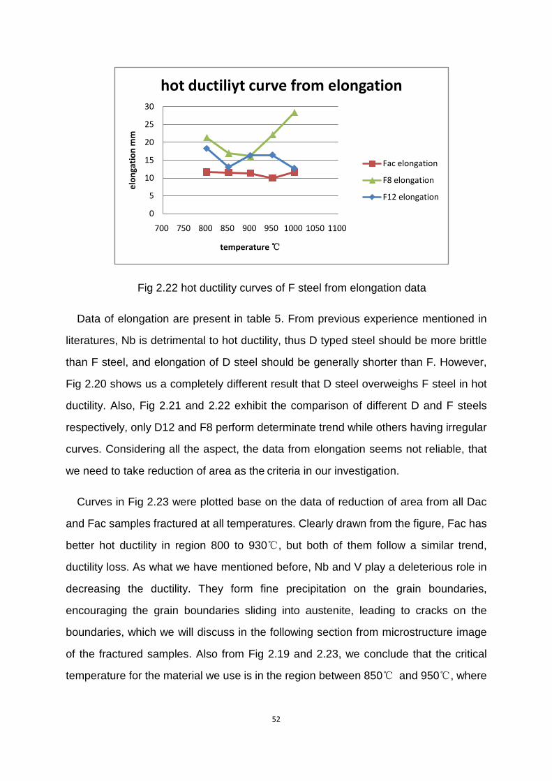
Fig 2.22 hot ductility curves of F steel from elongation data
Data of elongation are present in table 5. From previous experience mentioned in
literatures, Nb is detrimental to hot ductility, thus D typed steel should be more brittle
than F steel, and elongation of D steel should be generally shorter than F. However,
Fig 2.20 shows us a completely different result that D steel overweighs F steel in hot
ductility. Also, Fig 2.21 and 2.22 exhibit the comparison of different D and F steels
respectively, only D12 and F8 perform determinate trend while others having irregular
curves. Considering all the aspect, the data from elongation seems not reliable, that
we need to take reduction of area as the criteria in our investigation.
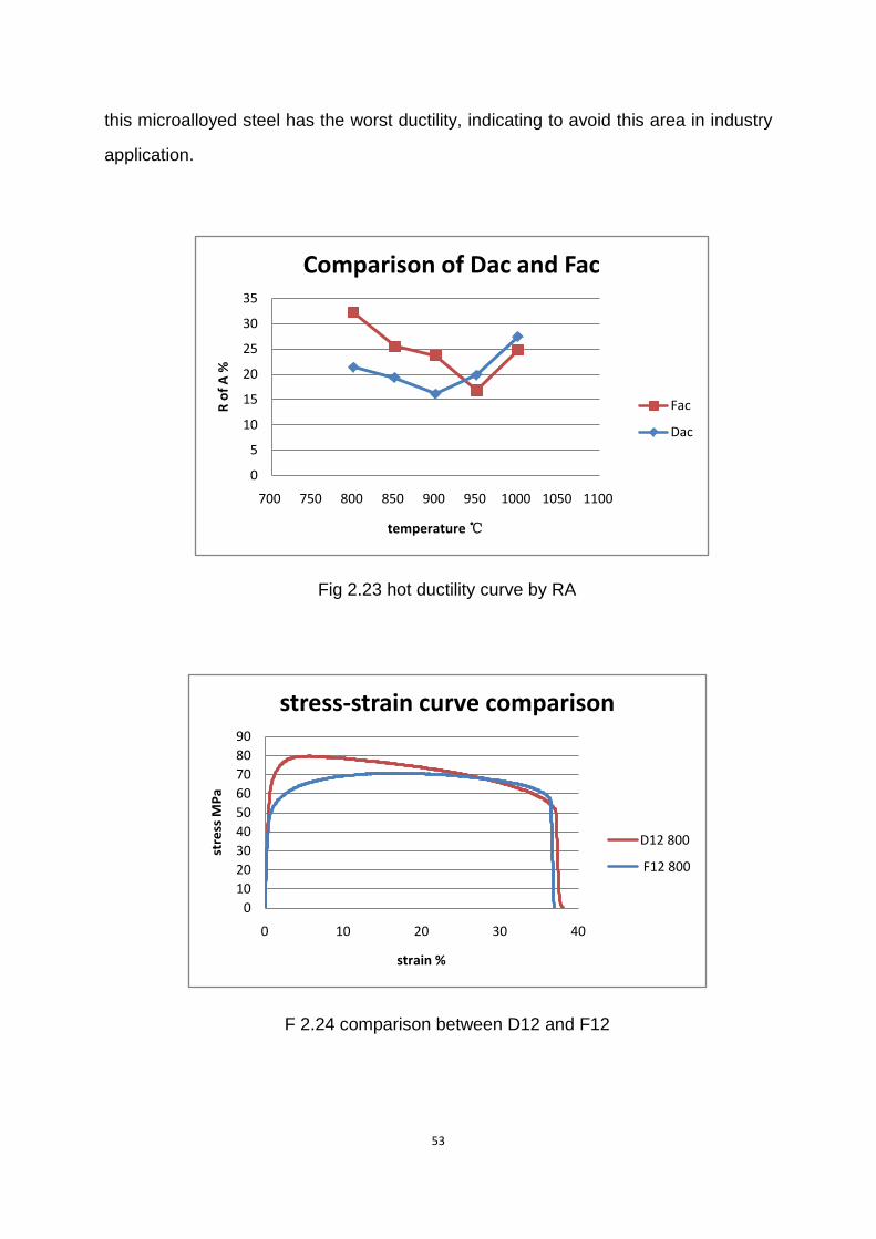
Curves in Fig 2.23 were plotted base on the data of reduction of area from all Dac
and Fac samples fractured at all temperatures. Clearly drawn from the figure, Fac has
better hot ductility in region 800 to 930℃, but both of them follow a similar trend,
ductility loss. As what we have mentioned before, Nb and V play a deleterious role in
decreasing the ductility. They form fine precipitation on the grain boundaries,
encouraging the grain boundaries sliding into austenite, leading to cracks on the
boundaries, which we will discuss in the following section from microstructure image
of the fractured samples. Also from Fig 2.19 and 2.23, we conclude that the critical
temperature for the material we use is in the region between 850℃ and 950℃, where
0
5
10
15
20
25
30
700 750 800 850 900 950 1000 1050 1100
elon
gati
on m
m
temperature ℃
hot ductiliyt curve from elongation
Fac elongation
F8 elongation
F12 elongation
53
this microalloyed steel has the worst ductility, indicating to avoid this area in industry
application.
Fig 2.23 hot ductility curve by RA
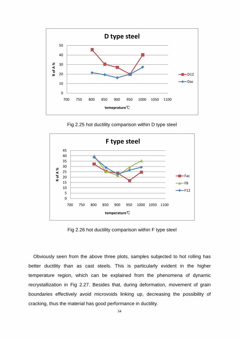
F 2.24 comparison between D12 and F12
0
5
10
15
20
25
30
35
700 750 800 850 900 950 1000 1050 1100
R of
A %
temperature ℃
Comparison of Dac and Fac
Fac
Dac
0102030405060708090
0 10 20 30 40
stre
ss M
Pa
strain %
stress-strain curve comparison
D12 800
F12 800
54
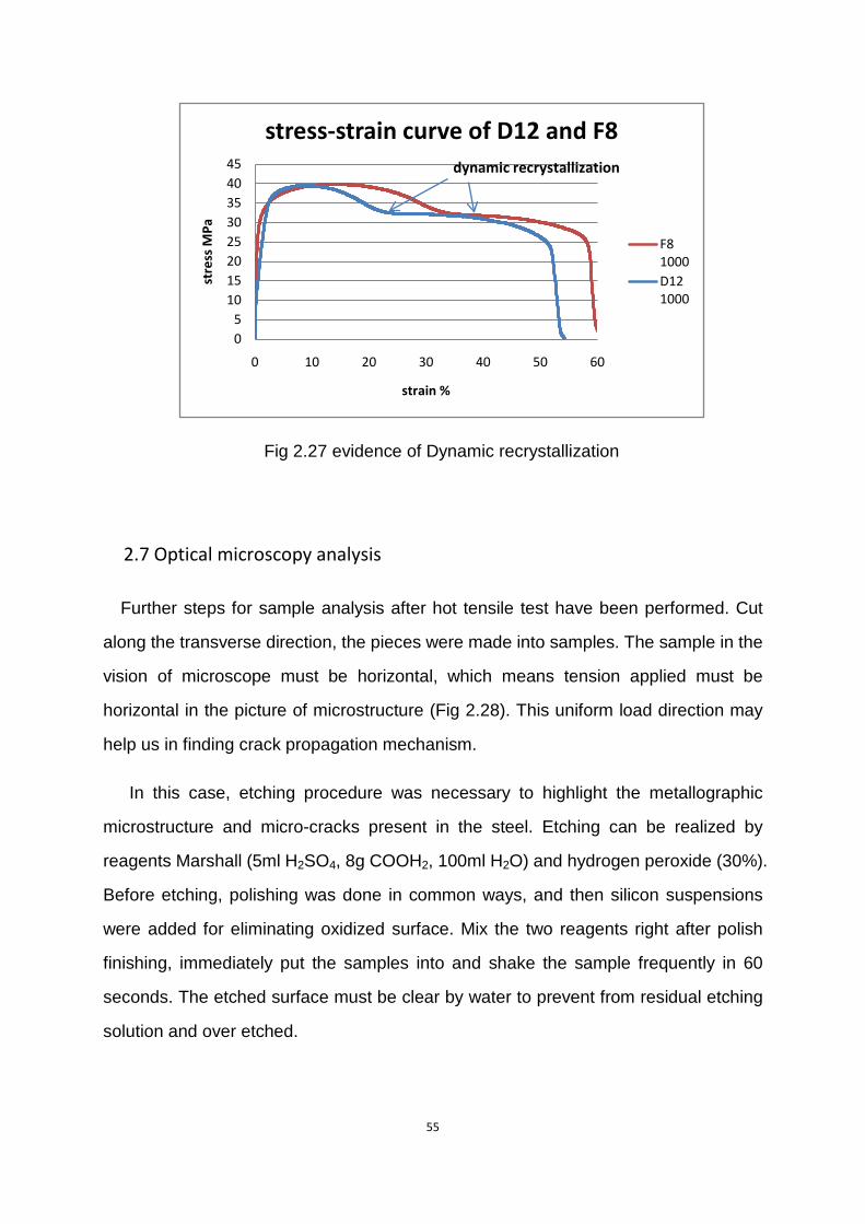
Fig 2.25 hot ductility comparison within D type steel
Fig 2.26 hot ductility comparison within F type steel
Obviously seen from the above three plots, samples subjected to hot rolling has
better ductility than as cast steels. This is particularly evident in the higher
temperature region, which can be explained from the phenomena of dynamic
recrystallization in Fig 2.27. Besides that, during deformation, movement of grain
boundaries effectively avoid microvoids linking up, decreasing the possibility of
cracking, thus the material has good performance in ductility.
0
10
20
30
40
50
700 750 800 850 900 950 1000 1050 1100
R of
A %
temeprature℃
D type steel
D12
Dac
05
1015202530354045
700 750 800 850 900 950 1000 1050 1100
R of
A %
temperature℃
F type steel
Fac
F8
F12
55
Fig 2.27 evidence of Dynamic recrystallization
2.7 Optical microscopy analysis
Further steps for sample analysis after hot tensile test have been performed. Cut
along the transverse direction, the pieces were made into samples. The sample in the
vision of microscope must be horizontal, which means tension applied must be
horizontal in the picture of microstructure (Fig 2.28). This uniform load direction may
help us in finding crack propagation mechanism.
In this case, etching procedure was necessary to highlight the metallographic
microstructure and micro-cracks present in the steel. Etching can be realized by
reagents Marshall (5ml H2SO4, 8g COOH2, 100ml H2O) and hydrogen peroxide (30%).
Before etching, polishing was done in common ways, and then silicon suspensions
were added for eliminating oxidized surface. Mix the two reagents right after polish
finishing, immediately put the samples into and shake the sample frequently in 60
seconds. The etched surface must be clear by water to prevent from residual etching
solution and over etched.
05
1015202530354045
0 10 20 30 40 50 60
stre
ss M
Pa
strain %
stress-strain curve of D12 and F8
F8 1000D12 1000
dynamic recrystallization
56
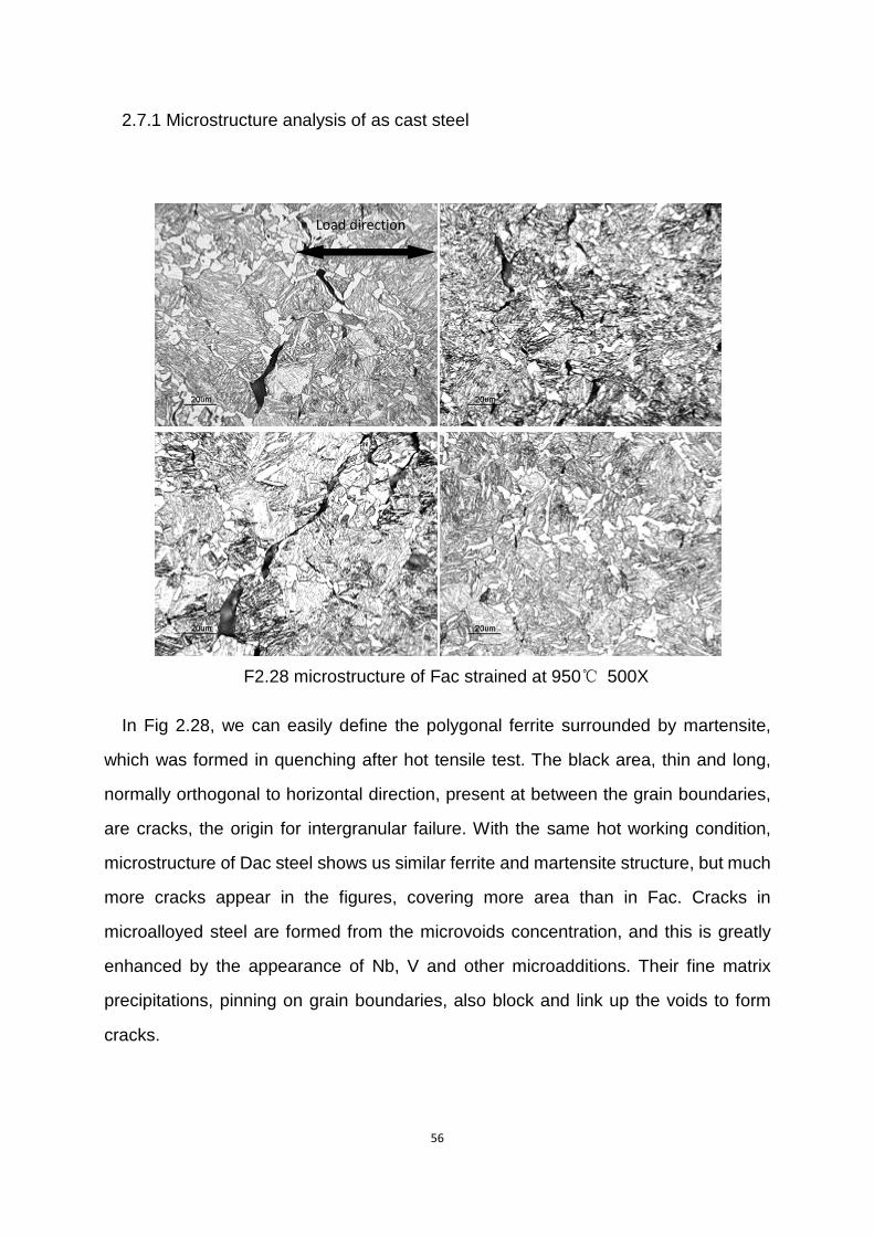
2.7.1 Microstructure analysis of as cast steel
F2.28 microstructure of Fac strained at 950℃ 500X
In Fig 2.28, we can easily define the polygonal ferrite surrounded by martensite,
which was formed in quenching after hot tensile test. The black area, thin and long,
normally orthogonal to horizontal direction, present at between the grain boundaries,
are cracks, the origin for intergranular failure. With the same hot working condition,
microstructure of Dac steel shows us similar ferrite and martensite structure, but much
more cracks appear in the figures, covering more area than in Fac. Cracks in
microalloyed steel are formed from the microvoids concentration, and this is greatly
enhanced by the appearance of Nb, V and other microadditions. Their fine matrix
precipitations, pinning on grain boundaries, also block and link up the voids to form
cracks.
Load direction
57
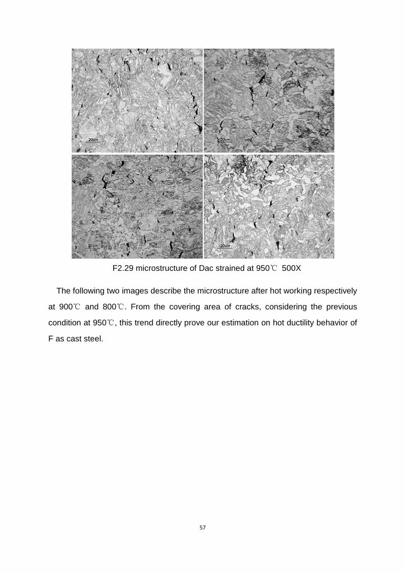
F2.29 microstructure of Dac strained at 950℃ 500X
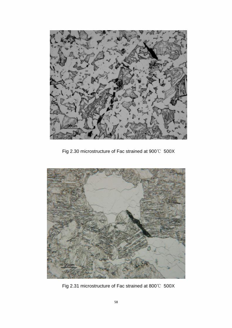
The following two images describe the microstructure after hot working respectively
at 900℃ and 800℃. From the covering area of cracks, considering the previous
condition at 950℃, this trend directly prove our estimation on hot ductility behavior of
F as cast steel.
58
Fig 2.30 microstructure of Fac strained at 900℃ 500X
Fig 2.31 microstructure of Fac strained at 800℃ 500X
59
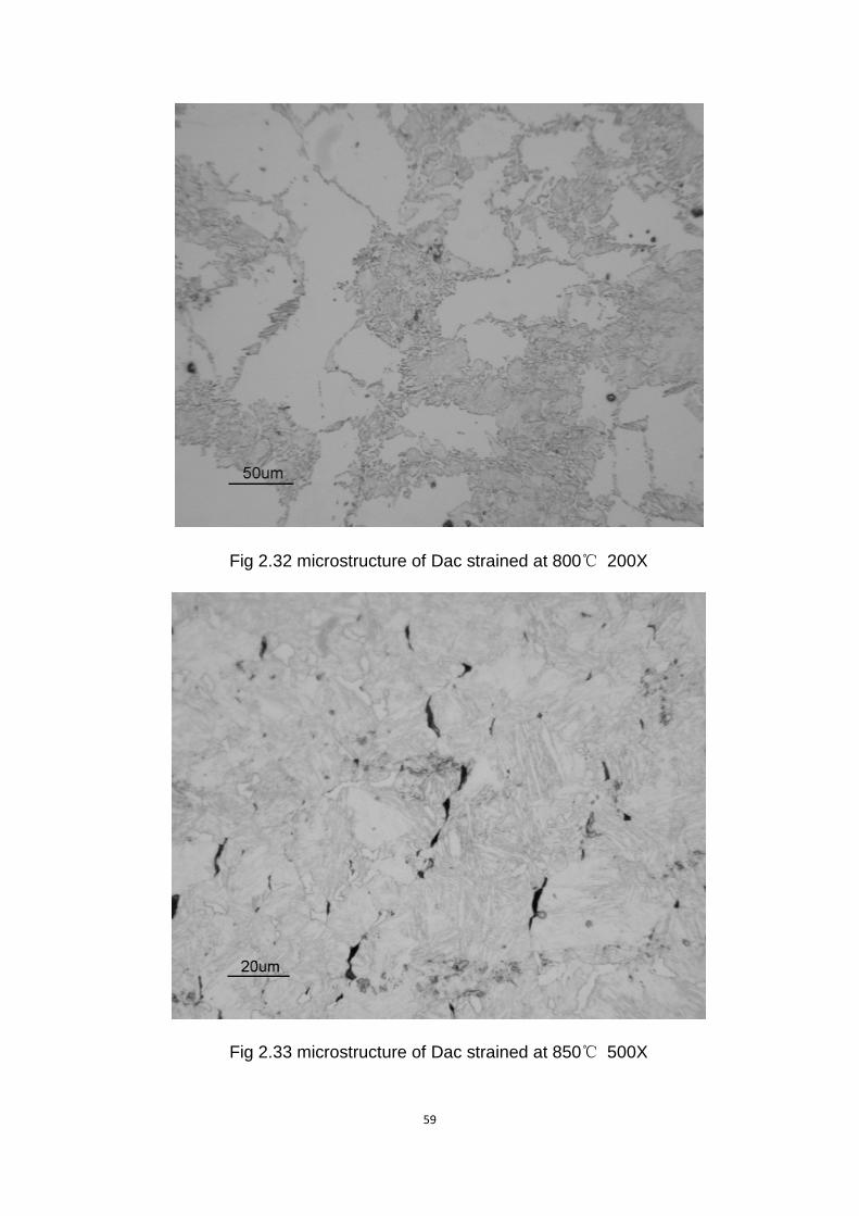
Fig 2.32 microstructure of Dac strained at 800℃ 200X
Fig 2.33 microstructure of Dac strained at 850℃ 500X
60
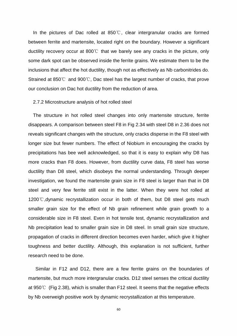
In the pictures of Dac rolled at 850℃, clear intergranular cracks are formed
between ferrite and martensite, located right on the boundary. However a significant
ductility recovery occur at 800℃ that we barely see any cracks in the picture, only
some dark spot can be observed inside the ferrite grains. We estimate them to be the
inclusions that affect the hot ductility, though not as effectively as Nb carbonitrides do.
Strained at 850℃ and 900℃, Dac steel has the largest number of cracks, that prove
our conclusion on Dac hot ductility from the reduction of area.
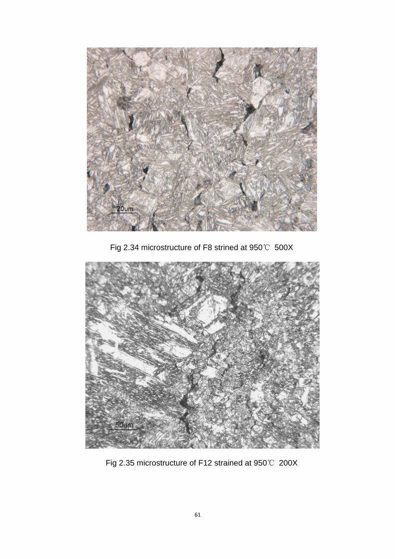
2.7.2 Microstructure analysis of hot rolled steel
The structure in hot rolled steel changes into only martensite structure, ferrite
disappears. A comparison between steel F8 in Fig 2.34 with steel D8 in 2.36 does not
reveals significant changes with the structure, only cracks disperse in the F8 steel with
longer size but fewer numbers. The effect of Niobium in encouraging the cracks by
precipitations has bee well acknowledged, so that it is easy to explain why D8 has
more cracks than F8 does. However, from ductility curve data, F8 steel has worse
ductility than D8 steel, which disobeys the normal understanding. Through deeper
investigation, we found the martensite grain size in F8 steel is larger than that in D8
steel and very few ferrite still exist in the latter. When they were hot rolled at
1200℃,dynamic recrystallization occur in both of them, but D8 steel gets much
smaller grain size for the effect of Nb grain refinement while grain growth to a
considerable size in F8 steel. Even in hot tensile test, dynamic recrystallization and
Nb precipitation lead to smaller grain size in D8 steel. In small grain size structure,
propagation of cracks in different direction becomes even harder, which give it higher
toughness and better ductility. Although, this explanation is not sufficient, further
research need to be done.
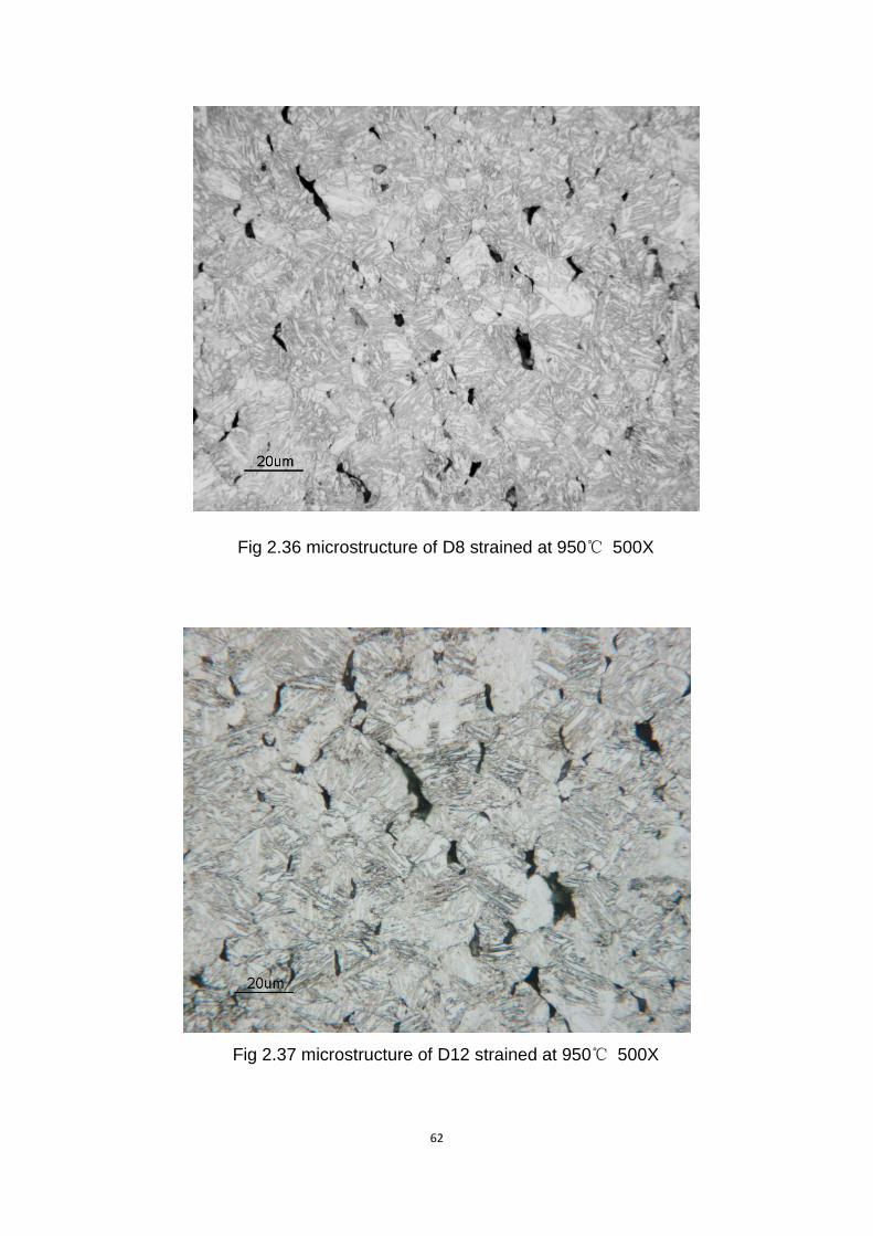
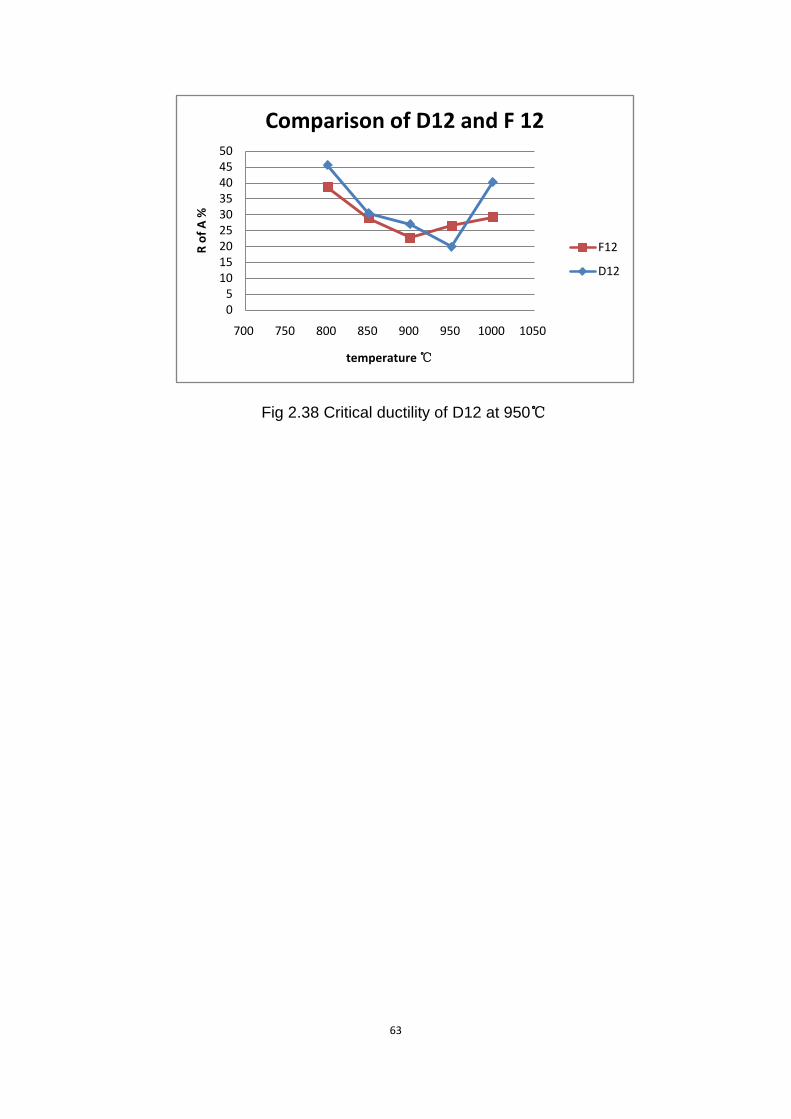
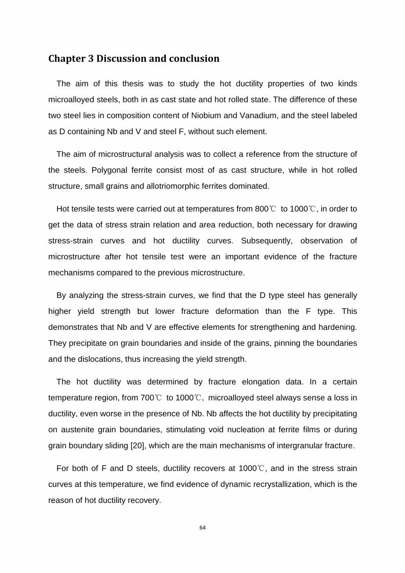
Similar in F12 and D12, there are a few ferrite grains on the boundaries of
martensite, but much more intergranular cracks. D12 steel senses the critical ductility
at 950℃ (Fig 2.38), which is smaller than F12 steel. It seems that the negative effects
by Nb overweigh positive work by dynamic recrystallization at this temperature.
61
Fig 2.34 microstructure of F8 strined at 950℃ 500X
Fig 2.35 microstructure of F12 strained at 950℃ 200X
62
Fig 2.36 microstructure of D8 strained at 950℃ 500X
Fig 2.37 microstructure of D12 strained at 950℃ 500X
63
Fig 2.38 Critical ductility of D12 at 950℃
05
101520253035404550
700 750 800 850 900 950 1000 1050
R of
A %
temperature ℃
Comparison of D12 and F 12
F12
D12
64
Chapter 3 Discussion and conclusion
The aim of this thesis was to study the hot ductility properties of two kinds
microalloyed steels, both in as cast state and hot rolled state. The difference of these
two steel lies in composition content of Niobium and Vanadium, and the steel labeled
as D containing Nb and V and steel F, without such element.
The aim of microstructural analysis was to collect a reference from the structure of
the steels. Polygonal ferrite consist most of as cast structure, while in hot rolled
structure, small grains and allotriomorphic ferrites dominated.
Hot tensile tests were carried out at temperatures from 800℃ to 1000℃, in order to
get the data of stress strain relation and area reduction, both necessary for drawing
stress-strain curves and hot ductility curves. Subsequently, observation of
microstructure after hot tensile test were an important evidence of the fracture
mechanisms compared to the previous microstructure.
By analyzing the stress-strain curves, we find that the D type steel has generally
higher yield strength but lower fracture deformation than the F type. This
demonstrates that Nb and V are effective elements for strengthening and hardening.
They precipitate on grain boundaries and inside of the grains, pinning the boundaries
and the dislocations, thus increasing the yield strength.
The hot ductility was determined by fracture elongation data. In a certain
temperature region, from 700℃ to 1000℃, microalloyed steel always sense a loss in
ductility, even worse in the presence of Nb. Nb affects the hot ductility by precipitating
on austenite grain boundaries, stimulating void nucleation at ferrite films or during
grain boundary sliding [20], which are the main mechanisms of intergranular fracture.
For both of F and D steels, ductility recovers at 1000℃, and in the stress strain
curves at this temperature, we find evidence of dynamic recrystallization, which is the
reason of hot ductility recovery.
65
The analysis of microstructure after hot tensile tests was aim at defining the
microstructure and counting the crack number and area. Martensite, formed during
quenching from the high temperature of the tests, is the main structure. Microaddition
precipitation induced voids, at the grain boundaries leading to cracks. We found that
the cracks in D steel were normally greater than those in F steel and their trend within
the same steel followed the trend of the hot ductility curves. According to our research,
a more cracked structure usually has lower ductility. Nevertheless, in comparison with
the as cast steel and hot rolled steel, D12 steel has much more cracks than Dac, but it
has much better hot ductility simultaneously.
Drawn from both the two aspects, hot ductility curves and cracks numbers, the
critical temperature for hot ductility is between 850℃ and 950℃.
66
References [1] W.B.Morrison, “Overview of microalloying in steel”, Proceedings of Vanitec International Symposium, (2000) [2] M.Korchynsky, “A New Role for Microalloyed Steels − Adding Economic Value”, Infacon, 9 (2001) [3] L. Meyer, F. Heisterkamp and W. Mueschenborn, “Columbian Titanium and Vanadium in Normalised, Thermomechanically Treated and Cold Rolled Steels,” Microalloying '75, (New York, NY: Union Carbide Corporation, 1977), 153-167. [4] J. Adamczyk “development of the microalloyed constructional steels”, JAMME 14 (2006) [5] C.M. Sellars, G.J. Davies (eds.), “Proc. Hot–Working and Forming Processes”, London (1979), 3. [6] W. Müschenborn et al., Proc. Int. Conf. Microalloying '95, Iron and Steel Soc., Pittsburgh PA, (1995), 35. [7] A. von den Steinen, S. Engineer, E. Horn and G. Preis, “Investigations of Steels with about 0.5% C and Small Addition of Vanadium or Niobium”, Stahl und Eisen, 95 (6) (1975), 209. [8] J. Stoeter and J. Kneller, Metal Progress, 3 (1985), 61. [9] J. H. Bucher and J. F. Held, “Microalloyed Cold Finished and Hot Rolled Bars”, SAE Technical Paper Series (Society of Automotive Engineers Inc., September 1981), No. 811003. [10] Rune Lagneborg, Tadeusz Siwecki, Stanislaw Zajac and Bevis Hutchinson, “The role of vanandium in microalloyed steel”, Scandinavian Journal of Metallurgy, 28 (5) (1999) [11] W.Saikaly, L.Charrin, A.Charai, X.Bano and C.Issartel, “The effect of thermomechanical processing on the precipitation in an industrial dual-phase steel microalloyed with titanium”, Metallurgical and Materials Transations A, 32 (8) (2001) [12] B. Mintz, s. Yueand J. J. Jonas, “Hot ductility of steels and its relationship to the problem of transverse cracking during continuous casting” Int. Mater. Rev 36 (5) (1991), 187-217 [13] B.Mintz, “The Influence of Composition on the Hot Ductility of Steels and to the Problem of Transverse Cracking”, ISIJ International, 39 (9) (1999), 833-855 [14] R.Abushosha, R.Vipond, and B.Mintz, “Influence of Titanium on hot ductility of as cast steel”, Mater. Sci. Technolo., 7, (1991), 613-621 [15] B.Mintz and Abushosha, “Influence of Vanadium on hot ductility of steel”, Ironmaking and Steelmaking, 20, (6), (1993), 445-452 [16] R.Abushosha, O. Comineli, et al., "Influence of Ti on hot ductility of C-Mn-Al steels" Materials Science and Technology 15, (1999), 278-286. [17] Comineli, O., R. Abushosha, et al., "Influence of titanium and nitrogen on hot ductility of C-Mn-Nb-Al steels", Materials Science and Technology, 15 (1999), 1058-1068. [18] H.G. Suzuki, S. Nishimura and S. Yamaguchi, “Characteristics of hot ductility in steels subjected to melting and solidification”, Trans. ISIJ, 22, (1982), 48-56. [19] B. Mintz and J.M. Arrowsmith, “Hot ductility behaviour of C-Mn-Nb-Al steels and its relationship to crack propagation during the straightening of continuously cast strand”, Met. Technol., 6, (1979), 24-32. [20] M.Vedani, D.Dellasega and A.Mannucci “Characterization of grain-boundary precipitates after hot-ductility tests of microalloyed steels”, ISIJ International, 49 (3) (2007), 446-452