Embed Size (px)
Citation preview
99
ARCHITECTURAL ENGINEERING AND DESIGN MANAGEMENT 2008 VOLUME 4 PAGES 99ndash120
Keywords ndash Fire evacuation layout improvement shapegrammar station design
INTRODUCTIONUnderground stations can broadly be divided into twomethods of construction cut and cover (ie excavatinga trench and recovering) and tunnelling The stationlayout is mostly comprised of the areas that arecommon to all stations and their spatial planning mustbe set out with a thorough understanding of passengercirculation patterns The station components namelythe ticket hall escalators concourses platforms etcall interact and connect in a coherent logical mannerwith the principal aim of transporting customerstoaway from trains as quickly and efficiently aspossible However achieving this aim must not bedetrimental to passenger safety which is paramount instation design (Smith et al 2003)
London has the largest oldest and one of the mostcomplex underground railway systems in the worlddating back to 1863 It has an excellent passengersafety record with its most notable tragic eventstaking place at the Kingrsquos Cross fire in November 1987and in the terrorist attacks of July 2005
The standards and regulations through whichLondon Underground (LU) operates its fire strategiesfor station design approvals are as follows
LU Station Planning Standards and Guidelines(SPSG 2007)
Building Regulations (exempt but still meetfunctional requirements)
1-080 The application of fire safety engineeringprinciples to LU premises
1-081 The design and installation of fireprotection systems
AbstractSpatial layout planning is an important part of the underground railway station design process taking intoaccount its need-driven nature and the resulting infrastructure that is sized on demand The predictedpassenger flow rates are the underlining factor and are divided into lsquolevels of servicersquo for space planningconsiderations This paper reports on the development of a knowledge-based computer design environmentcapable of generating multiple spatial layout solutions thus providing for more effective fire evacuationanalysis when compared with the traditional design process The developed programme titled SGEvac in thisresearch utilizes shape grammar theory to provide for automatic generation of solutions at the reference(preliminary) design level based on visual rules of shape recognition and replacement their connectivity andspatial relationships Although it has been developed to meet London Underground Station PlanningStandards and Guidelines (SPSG) and related codes of practice it has both the scope and potential forredevelopment to any other countryrsquos design legislation Novel shape grammar and functional logic designrules that incorporate station planning design knowledge and guidance are developed and specified alongwith the theoretical research Validation of the results thus far is discussed with a lsquotrain on fire in a stationrsquoevacuation scenario analysed
ARTICLE
Spatial Layout Planning in Sub-SurfaceRail Station Design for Effective FireEvacuationGraham Smith and Boris Ceranic
doi103763aedm20080078 copy 2008 Earthscan ISSN 1745-2007 (print) 1752-7589 (online) wwwearthscanjournalscom
1-082 Active fire protection systems and portablefire extinguishers
1-083 Passive fire protection systems 1-084 Maintenance of fire protection systems 1-085 Fire safety performance of materials 1-066 Emergency lighting HMRI Railway Safety Principles and Guidance
Part 2 Section B Regulatory Reform (Fire Safety) Order 2005 BS 5588 Fire precautions in the design
construction and use of buildings BS 7974 Application of fire safety engineering
principles to the design of buildings BS 8300 Design of buildings and their approaches
to meet the needs of disabled people
The figures for predicted passenger flow rates areobtained from Transport for London (TfL) According toTfL 2007 figures London Underground had over 1 billionpassenger journeys for the first time in its history whichis more than the entire national rail network Thus theresearch to improve both the evacuation and normalcirculation routes with regard to emergency evacuation(means of escape travelling distances position of fireexits circulation etc) could have an important benefitwhen designing large interchange stations under majorrefurbishment or new build consideration
THEORY AND APPLICATION OF SHAPEGRAMMAR The concept of shape grammar formalism is primarilyattributed to Stiny and Gips (1971) with majorcontributions made by Stiny (1977 1980) Flemming(1987) Knight (1995 1999) Chase (1996) Tapia(1999) Li (2003) and Liew (2003)
Shape grammar is a method of describing andcreating languages of designs where shapes aredevices for visual expression Their composition iscontrolled by preconceived rules in a very similar wayas to how grammar is used to arrange written wordsinto sentences The theory provides an approach forthe generation of composite shapes based onprinciples of recognition and replacement of aparticular shape Primitive shapes are transformedand combined to create more complex compositesthrough the application of predefined rules and soshape language emerges (Cha and Gero 1999)
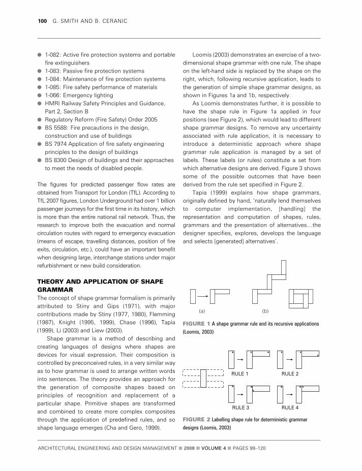
Loomis (2003) demonstrates an exercise of a two-dimensional shape grammar with one rule The shapeon the left-hand side is replaced by the shape on theright which following recursive application leads tothe generation of simple shape grammar designs asshown in Figures 1a and 1b respectively
As Loomis demonstrates further it is possible tohave the shape rule in Figure 1a applied in fourpositions (see Figure 2) which would lead to differentshape grammar designs To remove any uncertaintyassociated with rule application it is necessary tointroduce a deterministic approach where shapegrammar rule application is managed by a set oflabels These labels (or rules) constitute a set fromwhich alternative designs are derived Figure 3 showssome of the possible outcomes that have beenderived from the rule set specified in Figure 2
Tapia (1999) explains how shape grammarsoriginally defined by hand lsquonaturally lend themselvesto computer implementation [handling] therepresentation and computation of shapes rulesgrammars and the presentation of alternativeshellipthedesigner specifies explores develops the languageand selects [generated] alternativesrsquo
ARCHITECTURAL ENGINEERING AND DESIGN MANAGEMENT 2008 VOLUME 4 PAGES 99ndash120
100 G SMITH AND B CERANIC
(a) (b)
RULE 1 RULE 2
RULE 4RULE 3
FIGURE 1 A shape grammar rule and its recursive applications
(Loomis 2003)
FIGURE 2 Labelling shape rule for deterministic grammar
designs (Loomis 2003)
Stiny and Gips (1971) define shape grammar as
S = [VT VM R I] (1)
where VT is a finite set of shapes VM is a finite setof labels R is a finite set of shape rules and I is aninitial shape
In this research parameter VT is the finite set ofthe station infrastructure components shapes andVM is the finite set of labels that comprise thepossible station area permutations mapping twolsquolegally connectedrsquo components into a spatial relationwithin the overall layout R is the finite set of theshape connectivity rules composed of informationcontained in regulations and guidance documents interms of the area assignments adjacency and theirconnectivity I is an initial shape (ticket hall in theSGEvac programme)
In summary a proposed shape grammar systemconsists of a set of vocabulary elements (stationcomponents) a set of rewrite rules and a start stateStation layout can be considered in terms of compositeshape generation and its design process in terms oflogical sequence and deductive reasoning It is thisapproach based on the function of the building thatallows for a transition from lsquotraditionalrsquo layout planningto the computational shape grammar layoutgeneration that is proposed in this research Howeverits application depends directly upon the expertrsquosknowledge filtered into this rule-based approach
An additive shape grammar approach (Knight1999) is proposed as a suitable technique for
generating station layouts This approach is useful forthe irregular station boundaries derived from sitespecific conditions where designs are generatedfrom a core (the ticket hall) to which othercomponents are successively added
Knight (1995) remarks that the rules detailed inStinyrsquos Kindergarten paper (1980) can be preacutecised toexternalize a studentrsquos design ideas so that they canbe examined changed and communicated morereadily It is the choice of credible shape grammaralternatives that is important not the multitude ofsolutions themselves Good analytic grammars areboth efficient and descriptive revealing simplicity orregularities behind seemingly complex designs
STATION LAYOUT DESIGNCONSIDERATIONSPassenger space planning needs to be considered interms of peoplersquos procedures when they use theUnderground Initially customers will enter thecomplex from either street level or via a surfacestation stairwell A one- or two-way passage will thentake passengers to the unpaid side of the ticket hallwhere they will purchase a ticket before passingthrough to the paid side
Customers then descend using stairsescalatorslifts to platform level At both the top and bottom ofstairs and escalators there is a station componenttermed the run-off area The length of the run-offdepends on the peak passenger flow capacity of theescalatorstairwell and whether it connects to aplatform passageway or street It is an area wherepeople move away from the change in level orientatethemselves and make a decision of where to go next(SPSG 2007)
Generally at platform level people will journey tothe desired line to take them to their destination via afurther passageway or lobby area Some escalatorsstairs can exit directly onto platforms The travelprocess is reversed when alighting from a train andcontinuing to the surface
The predicted passenger flow rates and sitespecific conditions dictate both the number of railwaylines and the platform(s) configuration (side centre orstacked platform) Station composition must alsoconsider areas that are not sized by passengervolume demand but are required to ensure that the
ARCHITECTURAL ENGINEERING AND DESIGN MANAGEMENT 2008 VOLUME 4 PAGES 99ndash120
Spatial Layout Planning in Sub-Surface Rail Station Design for Effective Fire Evacuation 101
INITIAL SHAPE
INITIAL SHAPE
RULE 1 RULE 1 RULE 1 RULE 1
RULE 2RULE 2RULE 2RULE 3
FIGURE 3 Labelling shape rule for deterministic grammar
designs (Loomis 2003)
station operates satisfactorily on a daily basis Thestation managerrsquos office plant and staff roomscomputer rooms train technician rooms etc all needaccommodating in the proposed shape grammarformalism In addition ancillary accommodationsuch as the cleanerrsquos store police room publicitystore retail etc also have to be catered for
To aid designing and sizing infrastructure levelsof service as shown in Figure 4 are used by LondonUnderground These are based on the work of Fruin(1971) where a detailed study of crowd movementwas undertaken Level A represents free circulationwith subsequent levels growing progressively morerestricted in terms of people movement from B to Eculminating with level F that represents a completebreakdown in flow with numerous stoppages
The approach proposed in this research definesthe generic station layout arrangements from thelsquohigh-levelrsquo spatial site organization to the subsequent
specified components and their logical spatialallocations as illustrated in Figure 5 The consequentshape grammar rules can then be deduced taking intoaccount the predicted passenger flow rates fire safetystrategy and relevant design regulations
FIRE SAFETY DESIGN STRATEGYBefore any design commences a clear identificationand appraisal of the key constraints and parametersat the site layout planning stage is required Forexample deep foundations mains servicesarchaeological discoveries and even the RiverThames will affect station design decisionsFurthermore structural appraisals geotechnicalsurveys Statutory Undertaker searches groundcontamination testing environmental impactassessments and land acquisition etc all need to becarried out as part of a feasibility study before stationlayout planning at reference level commences
ARCHITECTURAL ENGINEERING AND DESIGN MANAGEMENT 2008 VOLUME 4 PAGES 99ndash120
102 G SMITH AND B CERANIC
Level of service A
Level of service D Level of service E Level of service F
Complete breakdown in trafficflow with many stoppages
Free circulationDescription (forqueuing areaswalkways andstairways)
Uni-directional flows andfree circulation Reverseand cross-flows withonly minor conflicts
Restricted circulation formost pedestriansSignificant difficulty forreverse and cross-flows
Restricted circulation for allpedestrians Intermittentstoppages and seriousdifficulties for reverse andcross-flows
Sligthly restricted circulationdue to difficulty inpassing others Reverse andcross-flows with difficulty
Level of service B Level of service C
FIGURE 4 London Underground levels of service (SPSG 2007)
Such constraints may be viewed in a positivecontext in terms of services already being providedhelping to justify the business case for a new stationDesign procurement strategies may include decisionssuch as locating toilet areas within x metres of anexisting sewer route or locating electrical plant roomswithin y metres of an existing electrical sub-station
In the real world parameters such as these constrict layout production and the choice ofinfrastructure component placement as opposed toleading to the production of many solutions that arelikely to be discarded when for example projectcosts are reviewed This level of regularity andrestriction typical in station design is very suitable
ARCHITECTURAL ENGINEERING AND DESIGN MANAGEMENT 2008 VOLUME 4 PAGES 99ndash120
Spatial Layout Planning in Sub-Surface Rail Station Design for Effective Fire Evacuation 103
SITE
CUT AND COVER STATION TUNNELLED STATION
TICKET HALL
UTS GATELINE (gateline dimensionsdetermine minimumticket hall width)
PASSAGEWAYS ONE- or TWO-WAY
(entrances exits determinea minimum uniform width)
ESCALATOR
STAIRS
RAMPS
TOP RUN-OFF
TRAVELATOR
PAID CONCOURSE SIDE
BOTTOM RUN-OFF
PASSAGEWAYS ONE -WAY or TWO-WAY
NON-PASSENGERSPACE ELEMENTS ATTICKET HALL LEVEL (egStation Managerrsquos Office)
PLATFORM LEVEL
SPACE ELEMENTS ATPLATFORM LEVEL (egplant rooms toilets etc)
SIDE PLATFORM CENTRE PLATFORM STACKED PLATFORM
No OF RAILWAY LINES
MEZZANINEOptional
MEZZANINE
DEEP
SHALLOW
LIFTS
NON-PASSENGER
FIGURE 5 lsquoHigh-levelrsquo layout hierarchy for generic station composition
for the application of a prescriptive shape grammarapproach
In parallel with the shape grammar developmentfunctional logic statements are proposed analogousto the qualitative design review as described in BS7974 Application of Fire Safety EngineeringPrinciples to the Design of Buildings The intention isto develop SGEvac procedures in a manner that isrecognized by fire safety engineers and designers inpractice The Department for the Environment (DOE)(1996) states that lsquothe architectural layout can have asignificant influence on peoplersquos movementComplexity in circulation routes may not be overcomenecessarily by signage these may not have beennoticed or they may have been forgotten as a resultof stressrsquo Hence station spatial requirements can bereviewed alongside a number of functional logicstatements devised in conjunction with the layoutplanning
For example lsquothe probability of successful escapethrough smoke diminishes sharply with (an increasein the) number of decision elements included in theescape pathrsquo (Hesketad 1999)
A functional logic statement response to theabove would be to minimize such decision elementsthus enabling faster egress Other examples offunctional logic statements employed are
no corridor or staircase will reduce in width alongescape routes
length of the passages are to be minimized maximize level areas to facilitate faster travel
speeds for escapees maintain uniformity to aid way-finding and relative
orientation evacuation and normal circulation routes are to
be the same exits will be prominent easily identifiable and
straightforward to reach
Such statements are intuitive by their nature and arepart of the qualitative reviews in the traditional designprocess Due to time constraints only a limitednumber of possible alternatives in terms of the spatiallayout improvements are ever considered if any Incontrast SGEvac offers not only the opportunity toconsider a significant number of possible alternatives
but also the means of quantitative assessment via fireevacuation simulations
Garling et al (1983) contend that newcomers to anenvironment first learn a number of salient locationsthen the paths in between and finally organize theacquired knowledge in a spatial system Indeedavoiding symmetry and lack of differentiation fromthe userrsquos viewpoint is a good practice for stationdesign considering perception of relative orientationin the station This is where interaction between thedesigner and computer program becomes essentialand it is in this context that the research argues therole of SGEvac as a computer-aided design tool notas a substitute for the designer
A comparative methodology overview is given inTable 1 The processes of BS 7974 the procurementof a general logic model (Galle and Kovacs 1992) andthe shape grammar development stages arebenchmarked against SGEvac procedures Thisperhaps has most relevance to fire safetyengineering since it is with this objective that theproposed shape grammar system is to be used inpractice
Research studies such as one by Magnusson et al(1995) note that fire safety engineering has motivateddesigners and regulators to examine alternative codecompliance approaches based on a greater relianceupon quantitative analyses This has led toreassessment of prescriptive approaches andconsequent adjustments as required It is nowaccepted that existing prescriptive practices shouldbe evaluated by quantitative performance-basedmethods as a part of the overall fire safety strategyas encouraged in the Regulatory Reform (Fire Safety)Order (RRFSO) 2005 SGEvac follows this trendaugmenting the array of tools available forperformance-based fire safety engineering design
There is obviously an inevitable need for designerinput and control at all stages of the design processDue to the potential necessity for deviation fromstandards via fire safety engineering judgement theproposed shape grammar approach cannot alonemodel project-specific concessions
Still the movement away from prescription viaBS 7974 and the RRFSO to risk-based judgementplaces computer-aided design tools such as SGEvacin a position of interdependency with other design
ARCHITECTURAL ENGINEERING AND DESIGN MANAGEMENT 2008 VOLUME 4 PAGES 99ndash120
104 G SMITH AND B CERANIC
criteria neither can be formulated in isolation Thisreinforces the view that computers will in future playan ever-increasing role in aiding and enabling thedesign teams but will never be able to replace them
SYSTEM DEVELOPMENTFigure 6 describes the modular approach proposedfor the system development offering the addedpotential of dual-purpose application in the designprocess It allows the designer to use the systemeither as a whole or to take advantage of itsindependent modules The system offers designerscomplete control over the shape grammarcomposition and layout modifications together withthe constant monitoring facilities and ability todiscard any solutions deemed to be lsquoinferiorrsquo
The proposed system is partitioned into threemain modules ndash lsquoexpert knowledgersquo lsquolayoutrsquo andlsquotestingrsquo modules The expert knowledge modulecaptures the expertise available to facilitate accurateshape grammar generations of layout design Thismodule provides the designer with the ability tointeractively reference Station Planning Standards
and Guidelines (and other relevant fire safetyregulations) allowing himher to make necessary site-specific decisions and to control the lsquohigh levelrsquo shapegrammar composition rules
The designer specifies passenger flow rates anddesignates the overall site boundary dimensions thatdefine the permissible station footprint The final exitpositions are also stipulated at this stage with theseoften being constrained by the existing builtenvironment
With this data supplied the shape grammargenerations commence in the layout module Thearea assignments adjacency requirements and layoutcomposition rules are defined in detail at this stageOnce the designer has made decisions with regard tothe layout composition the computer becomes thecentral tool for generating searching and logicallysorting through the permissible permutations ofpossible layouts The user has the option to auto-generate layouts (usually for sites without manyconstraints) or to manually control the layoutassembly (a decision normally associated with heavilyconstrained sites)
ARCHITECTURAL ENGINEERING AND DESIGN MANAGEMENT 2008 VOLUME 4 PAGES 99ndash120
Spatial Layout Planning in Sub-Surface Rail Station Design for Effective Fire Evacuation 105
TABLE 1 Methodology comparison BS 7974 PROCESSES GALLE AND KOVACS SHAPE GRAMMAR SGEvac
LOGIC MODELLING DEVELOPMENT IMPLEMENTATION
Assess benefits Identification Shape grammar Assess constraints
and constraints system identification identify benefitssite
boundariesfinal exit
positions
Qualitative design Conceptualization Initial state Station component
review identification and
interactions
Quantitative analysis Formalization Rules and shape Legislative compliance
language passenger flow figures
area assignments
Satisfactory Implementation Shape grammar Alternative station
unsatisfactory executions layouts generation
Report and review Testing Design analysis Testingvalidation
iterationsevolution of layouts generation
End Experimentation Experimentation
iterationsimprovements
The testing module is used to evaluate potentiallysuitable layouts at reference level by exporting them toAutoCAD via standard drawing data exchange formatand analysing them in the context of project-specificsite constraints and requirements A level of drawingdetail is then added and the layout solution is exportedto Simulex a building evacuation simulation software
package Once the occupant numbers and persongroups are assigned and the escape and verticalcirculation routes defined the simulation software iscapable of the accurate measurement of all travellingdistances creation of distance maps and calculation ofevacuation times for different fire scenarios (egdifferent group affiliations persons exiting via different
ARCHITECTURAL ENGINEERING AND DESIGN MANAGEMENT 2008 VOLUME 4 PAGES 99ndash120
106 G SMITH AND B CERANIC
EGY D ESIGNDesigner
Feasibility studiesProject brief requirements
Passenger flow data
DDE
DDE
Layout Production
Shape grammar rulesMultiple layout production
Layout Analysis
Layout interrogationsDesign team judgement
No
Yes
DXF
DXF
Yes
No
AutoCAD
Feed lsquoblock reference planrsquoresults into overall project
Improvedsolution identified
EXPERT KNOWLEDGE MODULE
Fire Strategy Design
LU SPSG4FSE legislation amp guidance
Infrastructure size calculationHigh level brief development
LAYOUT MODULE
Layout Composition
Area and adjacency planningLayout option appraisal
Layoutimproved
TESTING MODULE
AutoCAD
SGEvac export into CAD
Simulex
Fire evacuation scenarios
DesignerSGEvac
DDE ndash Database Data Exchange
DXF ndash Standard Drawing Data Exchange
FIGURE 6 Proposed SGEvac algorithm
routes and having delayed movement in response to afire alarm signal) The design team then assesses theresults against the qualitative fire safety design goalsset earlier to establish whether improvements toevacuation times have been made
DETAILED ANALYSIS OF STATIONCOMPONENTSIn conjunction with the site boundary final exitpositions and passenger flow specificationconsideration must also be given to the vertical sitedimension The shape grammar system assumes allfinal exits are at ground level with the ticket hall andplatform(s) being the other two elements that requirethe user to determine their depth relative to the finalexits In so doing SGEvac selects the correctinterchange components by an event-drivenmechanism that evaluates the height change andpassenger volume demand Thresholds for bothcriteria have been defined as shown in Table 2 andEquations 2ndash5
If H (height in mm) = 0 ndash 500 then I (infrastructure) = Ramp (2)
If H = 500 ndash 3000 and P (passengers) le 3000 then I = Stairway (3)
If H = 3000 ndash 5000 And P le 3000 then I = StairwayElse I = Escalator (4)
If H gt 5000 and P le 1000 then I = StairwayElse I = Escalator and Lift (5)
(where lsquoElsersquo denotes the mechanism for the choiceof the alternative infrastructure component if theoriginal condition is not satisfied)
The above constructs also condition the run-offdimensions associated with each of theinterchange components (between 4 m and 12 mas stipulated by SPSG) This being the case run-offs are used to size the ticket hall length Figure 7shows the paid side of the ticket hall with variabledistances shown between the escalator or staircaseand the gateline
The paid side of the ticket hall is always dictatedby run-off distance while the unpaid side is governedby two parameters the run-off and the concoursearea required for the heaviest 15-minute passengerflow If the maximum 15-minute passenger flowfigure multiplied by 1 m2 (say answer A) is larger inplan area than the product of the gateline widthmultiplied by the relevant run-off (say answer B) thenanswer A will be incorporated into the layout Thereverse is true if B is the greater number This ensuresthat the station is always sized appropriately
Figure 8 shows a ticket hall layout with thegateline dictating the width (denoted as Tick_H_wd)itself conditioned by the passenger flow figurescalculated as shown in Table 3 The table onlyevaluates entry flow requirements but SGEvac willrepeat the same process for exit gates to produce acorrectly sized gateline
In this case the maximum 15-minute passengerflow capacity size prevailed over the run-off to createthe unpaid side overall
The divide between the paid and unpaid side ofthe ticket hall is the sized according to Table 4
SGEvac shape rules mandate that entry gates arealways located adjacent to the ticket office queuingspace (designated as Q_TIW) to avoid conflictingpassenger entry and exit flows The LU standard is to
ARCHITECTURAL ENGINEERING AND DESIGN MANAGEMENT 2008 VOLUME 4 PAGES 99ndash120
Spatial Layout Planning in Sub-Surface Rail Station Design for Effective Fire Evacuation 107
TABLE 2 Interchange infrastructure selectionINFRASTRUCTURE REASON FOR SELECTION
Ramp Vertical rise between 0ndash05 m preferred to steps due to disabled access issues generally considered
people will travel faster on ramps than up or down steps
Stairs Vertical rise between 05ndash5 m but greater height available for selection if station has a light passenger flow
Escalator Vertical rise is minimum of 3 m for heavy passenger flow stations but used for lightmedium flow stations
above 5 m
Lift Vertical rise above 5 m also required for accessibility of disabled persons Lifts always used with escalators
not as a substitute
ARCHITECTURAL ENGINEERING AND DESIGN MANAGEMENT 2008 VOLUME 4 PAGES 99ndash120
108 G SMITH AND B CERANIC
Con_Area
Exit
UTS gates
6601900 2450
2400
EFW
Ticketoffice
POMcounter
4000
Tick_H_wd
1000
Run
-off
Entry
Q_space
Q_TIW
FIGURE 8 SGEvac ticket hall arrangement
Heavy flow escalator
Escalator
Staircase
Medium to Heavy flow
Medium to Heavy flow
Light flow escalator
Light flow
Heavy flow 12mMedium flow 8ndash12m
Light flow
Light flow 8m
Light flow 6m
Heavy flow
staircase to gateline
staircase to gateline 10m
Light flow
to gateline12mGateline
Gateline
EscalatorndashGateline
Total Run-off
Heavy flow 10mMedium flow 6ndash10m
StaircasendashGateline
Total Run-off
to gateline 8m
2m 4m 6m 8m 10m
2m 4m 6m
6m
8m 10m
12m
FIGURE 7 Passenger flow rate run-off requirements (SPSG 2007)
allow for 4 m (or a five-person queue) as shown inFigure 8 The overall gateline is defined by summingboth exit and entry gate numbers obtained from user-inputted passenger figures
The length of the ticket office interface with theticket hall is stipulated by the number of ticket issuingwindows (TIWs) plus excess fare windows (EFWs)TIWs always belong on the unpaid side of the tickethall and EFWs always on the paid side both forrevenue protection reasons This situation facilitates aprecise shape grammar labelling for the ticket officeto ticket hallqueue space connection
Passenger operated machine (POM) enclosures arenormally connected to the ticket hall ticket office andits own queue space (noted as Q_space in Figure 8)
To make shape rule specification manageable allstation areas are divided into groups arranged to suitthe most probable connection patterns in the stationTable 5 shows the group station managerrsquos officeexample with all other station components followingthe same concept
London Underground views its stations as largebasements (Weller 2007) and escape distances fromplatforms are based on agreed dispensations with theLondon Fire Brigade SGEvac respects thesedistances by placing restrictive labels on the platformso that they cannot be exceeded as demonstrated bythe example shown in Figure 9
SGEvac escape stair infrastructure may bepositioned up to 20 m from the end of platforms toavoid undesirable lsquodead endrsquo conditions The 45 mmaximum platform travel distance starts from thenearside junction of the two 33 m wide escapestaircases with the 45 m distance rule creating ashortfall in the platform centre of 34 m Generallylocating three interchange components (eg stairs
ARCHITECTURAL ENGINEERING AND DESIGN MANAGEMENT 2008 VOLUME 4 PAGES 99ndash120
Spatial Layout Planning in Sub-Surface Rail Station Design for Effective Fire Evacuation 109
TABLE 3 Gateline width calculationMETHOD WORKED EXAMPLE
Obtain peak hourly flow rate through Say 6500 peoplehr
ticket hall
Calculate 5-minute peak passenger flow 650012 = 541
Allowance for ticket rejection 541 + 20 = 561
Allowance for growth in use demand 561 x 110 = 617
Assume 125 people use each gate over
the 5-minute peak passenger flow period 617125 = 493
Round up gates to nearest whole number 5 gates required
TABLE 4 London Underground ticket hall gateline parametersregulations (SPSG 2007)EQUIPMENT DIMENSIONS (W X D) POSITIONARRANGEMENT
Combined manualequipment gate 1750 x 270 mm Height ndash 1300 mm Adjacent to ticket office Can include
1400 mm clear opening luggage facility
Manual gate ndash passenger 1750 x 270 mm Height ndash 1300 mm Adjacent to ticket office With more than 6
gateluggage port 900 mm ndash clearance and walkways in a single gateline or significant
outward opening interchange with mainline stations airport or
tourist traffic provide separate luggage chutes
Manual gate ndash single leaf 1394 mm Height ndash 1300 mm Beside the dedicated excess gates
with luggage port 695 mm clearance
Gateline attendance report 990 x 1240 mm Within the controlled zone but not necessarily
part of the gateline Usually close
Station control unit (SCU) 432 x 430 mm Should be installed within a secure enclosure
(which could be a ticket office) and also with
a clear view of the gates Controls and monitors
the station underground ticketing system
equipment
Manual emergency exit gates 1900 x 125 mm Adjacent to ticket office Add these gates rather
than adding extra UTS gates for evacuation
purposes
or escalators) at these distances will result incompliance with the Underground standards but itmay not always be possible (or practical for aninterchange situation) to procure such a layout
Lengths of station components are controlled bya range of criteria For the platform it is the length ofthe train vehicle for interchange components it isthe vertical height in the terms of the depth to theplatform level for passages it is the designated finalexit positions and the existing station areas alreadygenerated
Vector direction labels are underpinned by thepermissible union of compatible spaces two points ofcontact will be maintained so as not to restrict thewidth of connecting passenger areas This undueconstriction of passenger flow at the head of apassage also satisfies realistic construction practiceNon-passenger and ancillary area vector directions areas per project requirements and the successive areaadditions managed by the SGEvac rule groupings
To create alternative layouts SGEvac uses alsquorandomizersquo rule In this shape grammar rule initialstate infrastructure is generated as per guidelinesbut it can randomly change the location ofcomponent arrangements within the predefined
boundaries so that a number of possible alternativelayouts are produced The designs can then beinterrogated and ranked by their travelling distancesand against the qualitative functional logicstatements
The SGEvac design tool developed in this researchis based on a highly restrictive additive grammar ruleset due to SPSGrsquos prescriptive guidance and thenature of the layout planning problem As Grimsdaleand Chang (1996) argue many published grammarslack high-level reasoning during the iteration processsince they are often concerned with the developmentof shape grammar theories rather than their practicalapplications By contrast SGEvac being a practicalapplication has a complete set of primitive shapesonly possible to arrange in a certain way It thusprovides viable reference design layout compositionsbased on SPSG with further interventions possible bythe designer
SYSTEM DEVELOPMENT TO DATEThe SGEvac prototype is compiled within the Clanguage environment allowing for modular object-oriented programming (suitable for shape grammar)Figure 10 shows the main interface where the stationname and relevant LU fare zone are entered (whichimpacts on sizing infrastructure) as are the ticket halland platform depths the overall site boundaries andfinal exitsrsquo positions The peak passenger flow figuresover the relevant time interval of normally 3 hours arealso specified SGEvac is then capable of accuratelycalculating all passenger area infrastructure based onthe SPSG guidelines as already discussed
ARCHITECTURAL ENGINEERING AND DESIGN MANAGEMENT 2008 VOLUME 4 PAGES 99ndash120
110 G SMITH AND B CERANIC
TABLE 5 Station manager suite ndash shape rule connectionsELEMENT SHAPE RULE DESIGNATION CONNECTED COMPONENT GROUP ALLOCATION
Group station managerrsquos office SR_GSM_01 Ticket hall paid side GSM
SR_GSM_02 Ticket hall unpaid side
SR_GSM_03 GSM administration
SR_GSM_04 Duty station managerrsquos office
SR_GSM_05 Business managerrsquos office
SR_GSM_06 Administration
SR_GSM_07 Ticket office
SR_GSM_08 Police room
SR_GSM_09 Revenue protection examiner
SR_GSM_10 Interview room
140
Stair Stair
100 2020
4533
34
45
FIGURE 9 Platform escape distance SGEvac label restrictions
The history of auto-generated layouts is accessiblefrom this screen and the user is given the capabilityto delete and copy them (useful when minoralterations are required to produce an alternativelayout)
Shape labelling in the programme is multi-faceted which is necessary since many stationcomponents have various possible connections Anescalator for example may connect to a passagetravelator ramp escalator run-off stair run-off lift orthe ticket hall so all such connections need adding tothe component properties The SGEvac grouping ofcomponent interactions is accessed from menutoolbars that allow insertion of legislative compliantstation area connections as shown in Figure 11
Once the position and the depth of the ticket halland platform are specified the railway track is inserteddependent on the platform configuration The platformis the only possible connection to the track but thetrack can be positioned either side of platforms so thata side or centre (island) platform layout is possible
Non-passenger and ancillary areas are alsoselectable from the shape grammar library via property
windows for each station component eg the ticketoffice properties window as shown in Figure 12
Figure 13 shows examples of the layout modulestation components available in the SGEvacprogramme
Figure 14 shows the layout module interfaceInformation on the components (relative position inthe overall site layout and its absolute sizing) isdisplayed at the bottom of the screen once thecomponent is selected from the list In addition ameasurement bar (in metres) at the base of theinteractive design environment provides a sense ofscale for the designer
A checklist summarizes the station areas includedin the layout but a more detailed analysis is possiblevia a report function if required In addition to thisdetailed list a summary screen accessed from themain interface collates all specified components ineach generated layout This screen lists all passengernon-passenger and ancillary areas in their respectivecategories with infrastructure width data ofpassenger areas also summarized It also has anevacuation summary where the train frequency is
ARCHITECTURAL ENGINEERING AND DESIGN MANAGEMENT 2008 VOLUME 4 PAGES 99ndash120
Spatial Layout Planning in Sub-Surface Rail Station Design for Effective Fire Evacuation 111
FIGURE 10 SGEvac main interface
specified and the train evacuation load (taken as peaklsquorush hourrsquo loading) is displayed This section of thesummary screen is useful for input into Simulexwhere fire evacuation test runs of the building layoutcan be implemented
The lsquoshow hierarchyrsquo function in Figure 15 allowsdesign team members to view the progression ofdesigns by superimposing connecting lines betweenstation elements in the order of their compositionThis also serves as a safeguard against deleting
ARCHITECTURAL ENGINEERING AND DESIGN MANAGEMENT 2008 VOLUME 4 PAGES 99ndash120
112 G SMITH AND B CERANIC
FIGURE 12 SGEvac ticket office properties window
FIGURE 11 SGEvac properties window
components out of sequence that could lead to aninvalid solution
Once auto-generated layouts are complete withcorrectly sized and legitimately connected stationcomponents manual insertion of non-passenger areaswould then commence Upon completion thegenerated layout is transferred to AutoCAD via dxf fileformat as shown in Figure 16 Once in AutoCAD thelayout has a level of detail added by the designer suchas door openings passage connections fire escapeopenings etc so that passenger flows may beassessed It is then exported to Simulex for fireevacuation simulation analysis again via dxf file format
Simulex understands any voids as potentialcirculation routes treating the rest as solid andpermanent obstructions ie walls internal structuralelements permanent fixtures etc Since its solutionoperates in a two-dimensional environment for whatin effect is a three-dimensional problem the means
of vertical circulation (eg staircases) have to beestablished True lengths of staircases must bespecified based on the total length of all flights(sloping length) and the intermediate rests The fireexits need to be defined both in terms of theirlocation and width The links have to be establishedto define the point of the connection between thefloors and staircasesescalatorsramps The travellingdistance maps are then calculated type and numberof occupants specified building populated and theevacuation simulation performed
SYSTEM TESTING AND VALIDATIONKuligowski and Peacock (2005) define and recommendthe following ways of validating evacuation models
validation against code requirements validation against fire drills or other peoplersquos
movement experimentstrials
ARCHITECTURAL ENGINEERING AND DESIGN MANAGEMENT 2008 VOLUME 4 PAGES 99ndash120
Spatial Layout Planning in Sub-Surface Rail Station Design for Effective Fire Evacuation 113
Gateline Vertical
Platform Right
Stairs Horizontal Stairs Vertical
Travelator Vertical
Ticket Hall
BMOAdmin Reception
Platform Top Ram Up Bottom Vertical
Lift Passage Horizontal
FIGURE 13 Examples of SGEvac station components
ARCHITECTURAL ENGINEERING AND DESIGN MANAGEMENT 2008 VOLUME 4 PAGES 99ndash120
114 G SMITH AND B CERANIC
FIGURE 15 SGEvac hierarchy function
FIGURE 14 Layout module graphical user interface
validation against literature on past evacuationexperiments
validation against other models third-party validation
Furthermore Galea (1999) deconstructs the validationprocess into four main areas ndash component testingfunctional testing qualitative validation andquantitative validation This approach is more suitablefor models such as SGEvac than for those based oncompliance with code requirements and hence it isthe one adopted for the validation in this research
Component testing is regarded as testingcomputer code that drives the model checking forelementary errors Functional validation involveschecking that the model possesses the ability to
exhibit the range of capabilities required to performthe desired simulations Component testing andfunctional validation for SGEvac is carried outagainst code requirements insofar that allcalculations for infrastructure sizing are evaluatedmanually so that the method and answer are knownto be correct It uses the Simulex program to aid themodelling of people movement and to test thehypothesis of improvement to evacuation timesthus relying on Simulexrsquos own rigorous validationprocess Simulex has been used extensively inpractice as well as a validating model for otherevacuation softwares (Kuligowski and Peacock2005) SGEvac has gone through its initialcompletion and validation process with finalvalidation proposed for the end of the year
ARCHITECTURAL ENGINEERING AND DESIGN MANAGEMENT 2008 VOLUME 4 PAGES 99ndash120
Spatial Layout Planning in Sub-Surface Rail Station Design for Effective Fire Evacuation 115
FIGURE 16 Auto-generated SGEvac station layout export file for fire
evacuation simulation in Simulex
FIRE EVACUATION SIMULATION RESULTSThe considered lsquotrain on fire in stationrsquo scenario takesinto account the service interval of 333 minutes(based on 18 trains per hour) the crush capacity of afour-car train together with the number of peoplewaiting on the platform after cancellation of oneservice (ie after 666 minutes) On the oppositeplatform the evacuation load is taken to be thenormal boardingalighting load assuming nocancellations to services (50 of all boarders andalighters)
Evacuation load predictions were based on TfL2006 projected passenger flows with an averageflow of 36 peopleminute for boarders and 123peopleminute for boarders and alighters combinedThe train crush capacity was averaged at 165peoplecar The simulation also models evacuationfrom the ticket hall level to assess the impact ofdispersing crowds at peak times in this part of thestation From these figures the total evacuation loadwas calculated as follows
Platform 1 Boarders (36 x 666 min) = 240Train crush load (165 x 4) = 660
Platform 2 Boarders and alighters
(123 x 05 x 333 min) = 205Ticket hall = 470Total station evacuation load = 1575 people
The simulation results have been captured as imagesat 25 50 100 and 300 second intervals respectivelyfor both platform and ticket hall levels as shown inFigures 17 to 20
The provided means of escape follow LU SPSG4requirements insofar that the maximum travellingdistance on a platform to an exit is no more than 45 m (ie exits must be no more than 90 m apart) andthat the dead-end travelling distance is no more than20 m to an exit Hence each platform is provided withthree exits The MIPsrsquo (mobility impaired persons)means of escape is provided from both ends ofplatforms via emergency evacuation lifts Totalevacuation time (ie all people reaching an exit onticket hallground level) was 5 minutes and
24 seconds with the platform and train load clearedwithin 3 minutes and 5 seconds This is within therequirements to evacuate the platform and train loadwithin 4 minutes with all people reaching a fire-separated route within 6 minutes (the ticket hall is notclassed as a fire-separated route)
The performed simulation was based on theminimum travelling distance maps resulting in eachperson exiting via the nearest fire exit route Theaverage 10 second lsquotime to start to moversquo wasassigned to all occupants in order to accommodatefor real world people behaviour commonly reportedby fire evacuation research studies The boarders onthe end of both platforms (including most peoplefrom end carriages of the train) evacuated viastaircasesMIP lifts directly to the ground level pointof escape The boarders situated around the middleof platforms together with the people from the twomiddle carriages used the central escalators to reachticket hall fire exits Additionally some people fromthe end carriages and some staffretail unitcustomers used this route as means of escape
In this lsquotrain on fire in stationrsquo scenario it wasassumed that none of the escapes routes areunavailable due to maintenance However furtherevacuation studies will investigate possible scenarioswhere one of the escalator routes may be unavailabledue to maintenance reasons
FUTURE RESEARCHIntended future work will concentrate on the furtherconditioning developing and modelling of shapegrammar design rules based on the outcomes of thefinal system validation and LU expertsrsquo feedbackFurther research is proposed on the development ofa novel layout optimization approach based on theshape grammar rules to investigate the evacuation-related parametric improvements in subsurfacesurface railway station design (eg minimizingtravelling distances)
The fire safety strategy in terms of performance-based fire risk design is an important aspirationalaspect of SGEvac requiring further research andliaison with experts to determine how such variedcriteria could be allied with layout planning This isparticularly important where deviation from standardsoccurs Thus further development of the expert
ARCHITECTURAL ENGINEERING AND DESIGN MANAGEMENT 2008 VOLUME 4 PAGES 99ndash120
116 G SMITH AND B CERANIC
ARCHITECTURAL ENGINEERING AND DESIGN MANAGEMENT 2008 VOLUME 4 PAGES 99ndash120
Spatial Layout Planning in Sub-Surface Rail Station Design for Effective Fire Evacuation 117
FIGURE 17 Station evacuation after 25 seconds
FIGURE 18 Station evacuation after 50 seconds
ARCHITECTURAL ENGINEERING AND DESIGN MANAGEMENT 2008 VOLUME 4 PAGES 99ndash120
118 G SMITH AND B CERANIC
FIGURE 19 Station evacuation after 100 seconds
FIGURE 20 Station evacuation after 300 seconds
knowledge database would be required particularlyin the light of frequent changes to legislation
On a more practical note it could be beneficial todevelop the system on a stand-alone modular basislinked to each generated station component A list offire safety strategy objectives and functional logicstatements can then be specified for commonlyrecurring items (such as emergency lighting fire alarmdetectors sprinkler heads etc) and spaced accordingto the designerrsquos wishes or via shape rule formulation
Site constraint issues would also benefit fromfuture development as well as a move towardsdevelopment of the 3D shape grammar version Oncedevised other relevant 3D modelling systems such ascomputational fluid dynamics (CFD) smoke movementsoftware could be utilized in conjunction with SGEvac
CONCLUSIONSThe computer-aided modelling environment underdevelopment is intended to act as a layout planning aidfor those who practice in sub-surfacesurface railwaystation design The system under developmentcarefully considers London Underground StationPlanning Standards and Guidelines together withother relevant fire safety regulations that influenceoverall fire strategy design The proposed computer-aided design environment (SGEvac) is based on highlyrestrictive additive shape grammar rules driven by akernel of key passenger flow information to generatestation plan solutions
The major benefit to the design team is the ability toreview multiple layouts of accurately sized and correctlyplaced infrastructure at the reference or preliminarystage of the station layout planning design process Timeis hence saved regarding different option appraisals andquantitative testing using evacuation software shouldlead to a choice of more effective layouts in relation tomeans of escape travelling distances and improvementin the total evacuation times Modifications to layoutsshould be straightforward and there is scope toefficiently assess travelling distances and evacuationtimes for each of the considered alternatives comparedwith a lsquotraditionalrsquo approach
The proposed novel shape grammar approach ismost suited to new-build stations or largerefurbishment projects where more design flexibilityexists Sites with many site-specific constraints have
an array of predetermined parameters and will mostlikely benefit from the manual operation of SGEvac
Use in other rail systems due to recurringinfrastructure components and inherent functionallogic related to the laying out of the stationcomponents is also feasible provided that shapeconnections and shape rules are corrected to reflectthat countryrsquos legislative requirements
The potential for station layout improvementswith regard to emergency evacuation is an area thatmerits research especially in scenarios that concernthe safety of the general public and form a vital partof Londonrsquos transportation system Potential layoutimprovements could not only benefit evacuationsituations but also enhance the through-flow ofpeople during peak travelling periods
ACKNOWLEDGEMENTS The authors wish to express their gratitude to JacobsEngineering (UK) Ltd which has sponsored theresearch and to London Underground Ltd forproviding the design guidance that is reproduced inthis paper and for authorising the use of the stationplans London Underground has not reviewed thispaper and the content is solely the authorsrsquo work Mr Robert Hutchinson is also thanked for hiscomputer programming assistance
AUTHOR CONTACT DETAILSGGrraahhaamm SSmmiitthh (corresponding author) Senior Architectural
Technologist Jacobs (UK) Ltd Cardinal Square North Point
10 Nottingham Road Derby DE1 3QT UK Tel +44 (0)1332 234482
fax +44 (0)1332 344558 e-mail grahampsmithjacobscomBBoorriiss CCeerraanniicc Programme Leader for BScBA (Hons) Architectural
Programmes Room Number 105 Faculty of Arts Design and
Technology University of Derby Markeaton Street Derby DE22
3AW UK Tel +44 (0)1332 593136 e-mail bceranicderbyacuk
REFERENCES BS 7974 2001 Application of Fire Safety Engineering Principles to the
Design of Buildings London BSI
Cha MY and Gero JS 1999 Style Learning Inductive Generalisation of
Architectural Shape Patterns Paichai University and Sydney University
co-paper
ARCHITECTURAL ENGINEERING AND DESIGN MANAGEMENT 2008 VOLUME 4 PAGES 99ndash120
Spatial Layout Planning in Sub-Surface Rail Station Design for Effective Fire Evacuation 119
Chase SC 1996 lsquoUsing logic to specify shapes and spatial relations in
design grammarsrsquo in Workshop notes Grammatical Design Fourth
International Conference on Artificial Intelligence in Design Stanford
University US June
Department of the Environment 1996 Design Principles of Fire Safety
London The Stationery Office Books
Flemming U 1987 lsquoMore than the sum of its parts the grammar of
Queen Anne housesrsquo in Environment and Planning B Planning and
Design 14 323ndash350
Fruin JJ 1971 Pedestrian Planning and Design New York Metropolitan
Association of Urban Designers and Environmental Planners
Galea ER 1999 lsquoA general approach to validating evacuation models with
an application to EXODUSrsquo in Journal of Fire Sciences 16 414ndash436
Galle P and Kovacs LB 1992 lsquoThe logic of worms a study in
architectural knowledge representationrsquo in Environment and Planning B
Planning and Design 19 5ndash31
Garling T Lindberg E and Mantyla T 1983 lsquoOrientation in buildings ndash
effects of familiarity visual access and orientation aidsrsquo in Journal of
Applied Psychology 68(1) 177ndash186
Grimsdale RL and Chang CW 1996 lsquoThe layout design language A
technique for generating layout plansrsquo in Computer Graphics Forum
15(2) 97ndash106
Heskestad AW 1999 lsquoPerformance in smoke of way guidance systemsrsquo
in Fire and Materials 23(6) 375ndash381
Knight T 1995 lsquoConstructive symmetryrsquo in Environment and Planning B
Planning and Design 22 419ndash450
Knight TW 1999 lsquoShape grammars six typesrsquo in Environment and
Planning B Planning and Design 26 15ndash31
Kuligowski ED and Peacock RD 2005 A Review of Building Evacuation
Models Technical Note 1471 National Institute of Standards and
Technology (NIST) Technology Administration US Department of
Commerce
Li A I-Kang 2003 lsquoThe Yingzao fashi in the information agersquo conference
paper for the Beaux-Arts Paul Philippe Cret and Twentieth Century
Architecture in China The University of Pennsylvania October
Liew H 2003 lsquoSGML ndash A shape grammar meta-languagersquo in Digital
Design 21st eCAADe Conference Proceedings Graz Austria September
639ndash648
Loomis B 2003 lsquoA note on generative design techniques SGGA a user
driven genetic algorithm for evolving non-deterministic shape grammarsrsquo
working paper Massachusetts Institute of Technology (MIT)
Magnusson SE Drysdale DD Fitzgerald RW Mowrer F
Quintiere JG Williamson RB and Zalosh RG 1995
lsquoA proposal for a model curriculum in fire safety engineeringrsquo
in Fire Safety Journal 25 9ndash10
Smith G Ceranic B and Fryer C 2003 lsquoDevelopment of CAD
environment for spatial layout optimisation in sub-surfacesurface rail
station designrsquo in Proceedings of International BIAT Conference The
British Museum London January 2003
SPSG 2007 London Underground Station Planning Standards and
Guidelines SPSG4 (1ndash371) London
Stiny G and Gips J 1971 lsquoShape grammars and the generative
specification of painting and sculpturersquo in Information Processing 71
1460ndash1465
Stiny G 1977 lsquoIce-ray a note on the generation of Chinese lattice
designsrsquo in Environment and Planning B Planning and Design 4 89ndash98
Stiny G 1980 lsquoKindergarten grammars designing with Froebelrsquos building
giftsrsquo in Environment and Planning B 3 409ndash462
Tapia M 1999 lsquoA visual implementation of a shape grammar systemrsquo in
Environment and Planning B Planning and Design 26(1) 59ndash73
Transport for London 2007 Tube Carries One Billion Passengers for First
Time wwwtflgovukcorporatemedianewscentre4770aspx
(accessed 24 March 2008)
Weller M 2007 London Underground private correspondence
ARCHITECTURAL ENGINEERING AND DESIGN MANAGEMENT 2008 VOLUME 4 PAGES 99ndash120
120 G SMITH AND B CERANIC
1-082 Active fire protection systems and portablefire extinguishers
1-083 Passive fire protection systems 1-084 Maintenance of fire protection systems 1-085 Fire safety performance of materials 1-066 Emergency lighting HMRI Railway Safety Principles and Guidance
Part 2 Section B Regulatory Reform (Fire Safety) Order 2005 BS 5588 Fire precautions in the design
construction and use of buildings BS 7974 Application of fire safety engineering
principles to the design of buildings BS 8300 Design of buildings and their approaches
to meet the needs of disabled people
The figures for predicted passenger flow rates areobtained from Transport for London (TfL) According toTfL 2007 figures London Underground had over 1 billionpassenger journeys for the first time in its history whichis more than the entire national rail network Thus theresearch to improve both the evacuation and normalcirculation routes with regard to emergency evacuation(means of escape travelling distances position of fireexits circulation etc) could have an important benefitwhen designing large interchange stations under majorrefurbishment or new build consideration
THEORY AND APPLICATION OF SHAPEGRAMMAR The concept of shape grammar formalism is primarilyattributed to Stiny and Gips (1971) with majorcontributions made by Stiny (1977 1980) Flemming(1987) Knight (1995 1999) Chase (1996) Tapia(1999) Li (2003) and Liew (2003)
Shape grammar is a method of describing andcreating languages of designs where shapes aredevices for visual expression Their composition iscontrolled by preconceived rules in a very similar wayas to how grammar is used to arrange written wordsinto sentences The theory provides an approach forthe generation of composite shapes based onprinciples of recognition and replacement of aparticular shape Primitive shapes are transformedand combined to create more complex compositesthrough the application of predefined rules and soshape language emerges (Cha and Gero 1999)
Loomis (2003) demonstrates an exercise of a two-dimensional shape grammar with one rule The shapeon the left-hand side is replaced by the shape on theright which following recursive application leads tothe generation of simple shape grammar designs asshown in Figures 1a and 1b respectively
As Loomis demonstrates further it is possible tohave the shape rule in Figure 1a applied in fourpositions (see Figure 2) which would lead to differentshape grammar designs To remove any uncertaintyassociated with rule application it is necessary tointroduce a deterministic approach where shapegrammar rule application is managed by a set oflabels These labels (or rules) constitute a set fromwhich alternative designs are derived Figure 3 showssome of the possible outcomes that have beenderived from the rule set specified in Figure 2
Tapia (1999) explains how shape grammarsoriginally defined by hand lsquonaturally lend themselvesto computer implementation [handling] therepresentation and computation of shapes rulesgrammars and the presentation of alternativeshellipthedesigner specifies explores develops the languageand selects [generated] alternativesrsquo
ARCHITECTURAL ENGINEERING AND DESIGN MANAGEMENT 2008 VOLUME 4 PAGES 99ndash120
100 G SMITH AND B CERANIC
(a) (b)
RULE 1 RULE 2
RULE 4RULE 3
FIGURE 1 A shape grammar rule and its recursive applications
(Loomis 2003)
FIGURE 2 Labelling shape rule for deterministic grammar
designs (Loomis 2003)
Stiny and Gips (1971) define shape grammar as
S = [VT VM R I] (1)
where VT is a finite set of shapes VM is a finite setof labels R is a finite set of shape rules and I is aninitial shape
In this research parameter VT is the finite set ofthe station infrastructure components shapes andVM is the finite set of labels that comprise thepossible station area permutations mapping twolsquolegally connectedrsquo components into a spatial relationwithin the overall layout R is the finite set of theshape connectivity rules composed of informationcontained in regulations and guidance documents interms of the area assignments adjacency and theirconnectivity I is an initial shape (ticket hall in theSGEvac programme)
In summary a proposed shape grammar systemconsists of a set of vocabulary elements (stationcomponents) a set of rewrite rules and a start stateStation layout can be considered in terms of compositeshape generation and its design process in terms oflogical sequence and deductive reasoning It is thisapproach based on the function of the building thatallows for a transition from lsquotraditionalrsquo layout planningto the computational shape grammar layoutgeneration that is proposed in this research Howeverits application depends directly upon the expertrsquosknowledge filtered into this rule-based approach
An additive shape grammar approach (Knight1999) is proposed as a suitable technique for
generating station layouts This approach is useful forthe irregular station boundaries derived from sitespecific conditions where designs are generatedfrom a core (the ticket hall) to which othercomponents are successively added
Knight (1995) remarks that the rules detailed inStinyrsquos Kindergarten paper (1980) can be preacutecised toexternalize a studentrsquos design ideas so that they canbe examined changed and communicated morereadily It is the choice of credible shape grammaralternatives that is important not the multitude ofsolutions themselves Good analytic grammars areboth efficient and descriptive revealing simplicity orregularities behind seemingly complex designs
STATION LAYOUT DESIGNCONSIDERATIONSPassenger space planning needs to be considered interms of peoplersquos procedures when they use theUnderground Initially customers will enter thecomplex from either street level or via a surfacestation stairwell A one- or two-way passage will thentake passengers to the unpaid side of the ticket hallwhere they will purchase a ticket before passingthrough to the paid side
Customers then descend using stairsescalatorslifts to platform level At both the top and bottom ofstairs and escalators there is a station componenttermed the run-off area The length of the run-offdepends on the peak passenger flow capacity of theescalatorstairwell and whether it connects to aplatform passageway or street It is an area wherepeople move away from the change in level orientatethemselves and make a decision of where to go next(SPSG 2007)
Generally at platform level people will journey tothe desired line to take them to their destination via afurther passageway or lobby area Some escalatorsstairs can exit directly onto platforms The travelprocess is reversed when alighting from a train andcontinuing to the surface
The predicted passenger flow rates and sitespecific conditions dictate both the number of railwaylines and the platform(s) configuration (side centre orstacked platform) Station composition must alsoconsider areas that are not sized by passengervolume demand but are required to ensure that the
ARCHITECTURAL ENGINEERING AND DESIGN MANAGEMENT 2008 VOLUME 4 PAGES 99ndash120
Spatial Layout Planning in Sub-Surface Rail Station Design for Effective Fire Evacuation 101
INITIAL SHAPE
INITIAL SHAPE
RULE 1 RULE 1 RULE 1 RULE 1
RULE 2RULE 2RULE 2RULE 3
FIGURE 3 Labelling shape rule for deterministic grammar
designs (Loomis 2003)
station operates satisfactorily on a daily basis Thestation managerrsquos office plant and staff roomscomputer rooms train technician rooms etc all needaccommodating in the proposed shape grammarformalism In addition ancillary accommodationsuch as the cleanerrsquos store police room publicitystore retail etc also have to be catered for
To aid designing and sizing infrastructure levelsof service as shown in Figure 4 are used by LondonUnderground These are based on the work of Fruin(1971) where a detailed study of crowd movementwas undertaken Level A represents free circulationwith subsequent levels growing progressively morerestricted in terms of people movement from B to Eculminating with level F that represents a completebreakdown in flow with numerous stoppages
The approach proposed in this research definesthe generic station layout arrangements from thelsquohigh-levelrsquo spatial site organization to the subsequent
specified components and their logical spatialallocations as illustrated in Figure 5 The consequentshape grammar rules can then be deduced taking intoaccount the predicted passenger flow rates fire safetystrategy and relevant design regulations
FIRE SAFETY DESIGN STRATEGYBefore any design commences a clear identificationand appraisal of the key constraints and parametersat the site layout planning stage is required Forexample deep foundations mains servicesarchaeological discoveries and even the RiverThames will affect station design decisionsFurthermore structural appraisals geotechnicalsurveys Statutory Undertaker searches groundcontamination testing environmental impactassessments and land acquisition etc all need to becarried out as part of a feasibility study before stationlayout planning at reference level commences
ARCHITECTURAL ENGINEERING AND DESIGN MANAGEMENT 2008 VOLUME 4 PAGES 99ndash120
102 G SMITH AND B CERANIC
Level of service A
Level of service D Level of service E Level of service F
Complete breakdown in trafficflow with many stoppages
Free circulationDescription (forqueuing areaswalkways andstairways)
Uni-directional flows andfree circulation Reverseand cross-flows withonly minor conflicts
Restricted circulation formost pedestriansSignificant difficulty forreverse and cross-flows
Restricted circulation for allpedestrians Intermittentstoppages and seriousdifficulties for reverse andcross-flows
Sligthly restricted circulationdue to difficulty inpassing others Reverse andcross-flows with difficulty
Level of service B Level of service C
FIGURE 4 London Underground levels of service (SPSG 2007)
Such constraints may be viewed in a positivecontext in terms of services already being providedhelping to justify the business case for a new stationDesign procurement strategies may include decisionssuch as locating toilet areas within x metres of anexisting sewer route or locating electrical plant roomswithin y metres of an existing electrical sub-station
In the real world parameters such as these constrict layout production and the choice ofinfrastructure component placement as opposed toleading to the production of many solutions that arelikely to be discarded when for example projectcosts are reviewed This level of regularity andrestriction typical in station design is very suitable
ARCHITECTURAL ENGINEERING AND DESIGN MANAGEMENT 2008 VOLUME 4 PAGES 99ndash120
Spatial Layout Planning in Sub-Surface Rail Station Design for Effective Fire Evacuation 103
SITE
CUT AND COVER STATION TUNNELLED STATION
TICKET HALL
UTS GATELINE (gateline dimensionsdetermine minimumticket hall width)
PASSAGEWAYS ONE- or TWO-WAY
(entrances exits determinea minimum uniform width)
ESCALATOR
STAIRS
RAMPS
TOP RUN-OFF
TRAVELATOR
PAID CONCOURSE SIDE
BOTTOM RUN-OFF
PASSAGEWAYS ONE -WAY or TWO-WAY
NON-PASSENGERSPACE ELEMENTS ATTICKET HALL LEVEL (egStation Managerrsquos Office)
PLATFORM LEVEL
SPACE ELEMENTS ATPLATFORM LEVEL (egplant rooms toilets etc)
SIDE PLATFORM CENTRE PLATFORM STACKED PLATFORM
No OF RAILWAY LINES
MEZZANINEOptional
MEZZANINE
DEEP
SHALLOW
LIFTS
NON-PASSENGER
FIGURE 5 lsquoHigh-levelrsquo layout hierarchy for generic station composition
for the application of a prescriptive shape grammarapproach
In parallel with the shape grammar developmentfunctional logic statements are proposed analogousto the qualitative design review as described in BS7974 Application of Fire Safety EngineeringPrinciples to the Design of Buildings The intention isto develop SGEvac procedures in a manner that isrecognized by fire safety engineers and designers inpractice The Department for the Environment (DOE)(1996) states that lsquothe architectural layout can have asignificant influence on peoplersquos movementComplexity in circulation routes may not be overcomenecessarily by signage these may not have beennoticed or they may have been forgotten as a resultof stressrsquo Hence station spatial requirements can bereviewed alongside a number of functional logicstatements devised in conjunction with the layoutplanning
For example lsquothe probability of successful escapethrough smoke diminishes sharply with (an increasein the) number of decision elements included in theescape pathrsquo (Hesketad 1999)
A functional logic statement response to theabove would be to minimize such decision elementsthus enabling faster egress Other examples offunctional logic statements employed are
no corridor or staircase will reduce in width alongescape routes
length of the passages are to be minimized maximize level areas to facilitate faster travel
speeds for escapees maintain uniformity to aid way-finding and relative
orientation evacuation and normal circulation routes are to
be the same exits will be prominent easily identifiable and
straightforward to reach
Such statements are intuitive by their nature and arepart of the qualitative reviews in the traditional designprocess Due to time constraints only a limitednumber of possible alternatives in terms of the spatiallayout improvements are ever considered if any Incontrast SGEvac offers not only the opportunity toconsider a significant number of possible alternatives
but also the means of quantitative assessment via fireevacuation simulations
Garling et al (1983) contend that newcomers to anenvironment first learn a number of salient locationsthen the paths in between and finally organize theacquired knowledge in a spatial system Indeedavoiding symmetry and lack of differentiation fromthe userrsquos viewpoint is a good practice for stationdesign considering perception of relative orientationin the station This is where interaction between thedesigner and computer program becomes essentialand it is in this context that the research argues therole of SGEvac as a computer-aided design tool notas a substitute for the designer
A comparative methodology overview is given inTable 1 The processes of BS 7974 the procurementof a general logic model (Galle and Kovacs 1992) andthe shape grammar development stages arebenchmarked against SGEvac procedures Thisperhaps has most relevance to fire safetyengineering since it is with this objective that theproposed shape grammar system is to be used inpractice
Research studies such as one by Magnusson et al(1995) note that fire safety engineering has motivateddesigners and regulators to examine alternative codecompliance approaches based on a greater relianceupon quantitative analyses This has led toreassessment of prescriptive approaches andconsequent adjustments as required It is nowaccepted that existing prescriptive practices shouldbe evaluated by quantitative performance-basedmethods as a part of the overall fire safety strategyas encouraged in the Regulatory Reform (Fire Safety)Order (RRFSO) 2005 SGEvac follows this trendaugmenting the array of tools available forperformance-based fire safety engineering design
There is obviously an inevitable need for designerinput and control at all stages of the design processDue to the potential necessity for deviation fromstandards via fire safety engineering judgement theproposed shape grammar approach cannot alonemodel project-specific concessions
Still the movement away from prescription viaBS 7974 and the RRFSO to risk-based judgementplaces computer-aided design tools such as SGEvacin a position of interdependency with other design
ARCHITECTURAL ENGINEERING AND DESIGN MANAGEMENT 2008 VOLUME 4 PAGES 99ndash120
104 G SMITH AND B CERANIC
criteria neither can be formulated in isolation Thisreinforces the view that computers will in future playan ever-increasing role in aiding and enabling thedesign teams but will never be able to replace them
SYSTEM DEVELOPMENTFigure 6 describes the modular approach proposedfor the system development offering the addedpotential of dual-purpose application in the designprocess It allows the designer to use the systemeither as a whole or to take advantage of itsindependent modules The system offers designerscomplete control over the shape grammarcomposition and layout modifications together withthe constant monitoring facilities and ability todiscard any solutions deemed to be lsquoinferiorrsquo
The proposed system is partitioned into threemain modules ndash lsquoexpert knowledgersquo lsquolayoutrsquo andlsquotestingrsquo modules The expert knowledge modulecaptures the expertise available to facilitate accurateshape grammar generations of layout design Thismodule provides the designer with the ability tointeractively reference Station Planning Standards
and Guidelines (and other relevant fire safetyregulations) allowing himher to make necessary site-specific decisions and to control the lsquohigh levelrsquo shapegrammar composition rules
The designer specifies passenger flow rates anddesignates the overall site boundary dimensions thatdefine the permissible station footprint The final exitpositions are also stipulated at this stage with theseoften being constrained by the existing builtenvironment
With this data supplied the shape grammargenerations commence in the layout module Thearea assignments adjacency requirements and layoutcomposition rules are defined in detail at this stageOnce the designer has made decisions with regard tothe layout composition the computer becomes thecentral tool for generating searching and logicallysorting through the permissible permutations ofpossible layouts The user has the option to auto-generate layouts (usually for sites without manyconstraints) or to manually control the layoutassembly (a decision normally associated with heavilyconstrained sites)
ARCHITECTURAL ENGINEERING AND DESIGN MANAGEMENT 2008 VOLUME 4 PAGES 99ndash120
Spatial Layout Planning in Sub-Surface Rail Station Design for Effective Fire Evacuation 105
TABLE 1 Methodology comparison BS 7974 PROCESSES GALLE AND KOVACS SHAPE GRAMMAR SGEvac
LOGIC MODELLING DEVELOPMENT IMPLEMENTATION
Assess benefits Identification Shape grammar Assess constraints
and constraints system identification identify benefitssite
boundariesfinal exit
positions
Qualitative design Conceptualization Initial state Station component
review identification and
interactions
Quantitative analysis Formalization Rules and shape Legislative compliance
language passenger flow figures
area assignments
Satisfactory Implementation Shape grammar Alternative station
unsatisfactory executions layouts generation
Report and review Testing Design analysis Testingvalidation
iterationsevolution of layouts generation
End Experimentation Experimentation
iterationsimprovements
The testing module is used to evaluate potentiallysuitable layouts at reference level by exporting them toAutoCAD via standard drawing data exchange formatand analysing them in the context of project-specificsite constraints and requirements A level of drawingdetail is then added and the layout solution is exportedto Simulex a building evacuation simulation software
package Once the occupant numbers and persongroups are assigned and the escape and verticalcirculation routes defined the simulation software iscapable of the accurate measurement of all travellingdistances creation of distance maps and calculation ofevacuation times for different fire scenarios (egdifferent group affiliations persons exiting via different
ARCHITECTURAL ENGINEERING AND DESIGN MANAGEMENT 2008 VOLUME 4 PAGES 99ndash120
106 G SMITH AND B CERANIC
EGY D ESIGNDesigner
Feasibility studiesProject brief requirements
Passenger flow data
DDE
DDE
Layout Production
Shape grammar rulesMultiple layout production
Layout Analysis
Layout interrogationsDesign team judgement
No
Yes
DXF
DXF
Yes
No
AutoCAD
Feed lsquoblock reference planrsquoresults into overall project
Improvedsolution identified
EXPERT KNOWLEDGE MODULE
Fire Strategy Design
LU SPSG4FSE legislation amp guidance
Infrastructure size calculationHigh level brief development
LAYOUT MODULE
Layout Composition
Area and adjacency planningLayout option appraisal
Layoutimproved
TESTING MODULE
AutoCAD
SGEvac export into CAD
Simulex
Fire evacuation scenarios
DesignerSGEvac
DDE ndash Database Data Exchange
DXF ndash Standard Drawing Data Exchange
FIGURE 6 Proposed SGEvac algorithm
routes and having delayed movement in response to afire alarm signal) The design team then assesses theresults against the qualitative fire safety design goalsset earlier to establish whether improvements toevacuation times have been made
DETAILED ANALYSIS OF STATIONCOMPONENTSIn conjunction with the site boundary final exitpositions and passenger flow specificationconsideration must also be given to the vertical sitedimension The shape grammar system assumes allfinal exits are at ground level with the ticket hall andplatform(s) being the other two elements that requirethe user to determine their depth relative to the finalexits In so doing SGEvac selects the correctinterchange components by an event-drivenmechanism that evaluates the height change andpassenger volume demand Thresholds for bothcriteria have been defined as shown in Table 2 andEquations 2ndash5
If H (height in mm) = 0 ndash 500 then I (infrastructure) = Ramp (2)
If H = 500 ndash 3000 and P (passengers) le 3000 then I = Stairway (3)
If H = 3000 ndash 5000 And P le 3000 then I = StairwayElse I = Escalator (4)
If H gt 5000 and P le 1000 then I = StairwayElse I = Escalator and Lift (5)
(where lsquoElsersquo denotes the mechanism for the choiceof the alternative infrastructure component if theoriginal condition is not satisfied)
The above constructs also condition the run-offdimensions associated with each of theinterchange components (between 4 m and 12 mas stipulated by SPSG) This being the case run-offs are used to size the ticket hall length Figure 7shows the paid side of the ticket hall with variabledistances shown between the escalator or staircaseand the gateline
The paid side of the ticket hall is always dictatedby run-off distance while the unpaid side is governedby two parameters the run-off and the concoursearea required for the heaviest 15-minute passengerflow If the maximum 15-minute passenger flowfigure multiplied by 1 m2 (say answer A) is larger inplan area than the product of the gateline widthmultiplied by the relevant run-off (say answer B) thenanswer A will be incorporated into the layout Thereverse is true if B is the greater number This ensuresthat the station is always sized appropriately
Figure 8 shows a ticket hall layout with thegateline dictating the width (denoted as Tick_H_wd)itself conditioned by the passenger flow figurescalculated as shown in Table 3 The table onlyevaluates entry flow requirements but SGEvac willrepeat the same process for exit gates to produce acorrectly sized gateline
In this case the maximum 15-minute passengerflow capacity size prevailed over the run-off to createthe unpaid side overall
The divide between the paid and unpaid side ofthe ticket hall is the sized according to Table 4
SGEvac shape rules mandate that entry gates arealways located adjacent to the ticket office queuingspace (designated as Q_TIW) to avoid conflictingpassenger entry and exit flows The LU standard is to
ARCHITECTURAL ENGINEERING AND DESIGN MANAGEMENT 2008 VOLUME 4 PAGES 99ndash120
Spatial Layout Planning in Sub-Surface Rail Station Design for Effective Fire Evacuation 107
TABLE 2 Interchange infrastructure selectionINFRASTRUCTURE REASON FOR SELECTION
Ramp Vertical rise between 0ndash05 m preferred to steps due to disabled access issues generally considered
people will travel faster on ramps than up or down steps
Stairs Vertical rise between 05ndash5 m but greater height available for selection if station has a light passenger flow
Escalator Vertical rise is minimum of 3 m for heavy passenger flow stations but used for lightmedium flow stations
above 5 m
Lift Vertical rise above 5 m also required for accessibility of disabled persons Lifts always used with escalators
not as a substitute
ARCHITECTURAL ENGINEERING AND DESIGN MANAGEMENT 2008 VOLUME 4 PAGES 99ndash120
108 G SMITH AND B CERANIC
Con_Area
Exit
UTS gates
6601900 2450
2400
EFW
Ticketoffice
POMcounter
4000
Tick_H_wd
1000
Run
-off
Entry
Q_space
Q_TIW
FIGURE 8 SGEvac ticket hall arrangement
Heavy flow escalator
Escalator
Staircase
Medium to Heavy flow
Medium to Heavy flow
Light flow escalator
Light flow
Heavy flow 12mMedium flow 8ndash12m
Light flow
Light flow 8m
Light flow 6m
Heavy flow
staircase to gateline
staircase to gateline 10m
Light flow
to gateline12mGateline
Gateline
EscalatorndashGateline
Total Run-off
Heavy flow 10mMedium flow 6ndash10m
StaircasendashGateline
Total Run-off
to gateline 8m
2m 4m 6m 8m 10m
2m 4m 6m
6m
8m 10m
12m
FIGURE 7 Passenger flow rate run-off requirements (SPSG 2007)
allow for 4 m (or a five-person queue) as shown inFigure 8 The overall gateline is defined by summingboth exit and entry gate numbers obtained from user-inputted passenger figures
The length of the ticket office interface with theticket hall is stipulated by the number of ticket issuingwindows (TIWs) plus excess fare windows (EFWs)TIWs always belong on the unpaid side of the tickethall and EFWs always on the paid side both forrevenue protection reasons This situation facilitates aprecise shape grammar labelling for the ticket officeto ticket hallqueue space connection
Passenger operated machine (POM) enclosures arenormally connected to the ticket hall ticket office andits own queue space (noted as Q_space in Figure 8)
To make shape rule specification manageable allstation areas are divided into groups arranged to suitthe most probable connection patterns in the stationTable 5 shows the group station managerrsquos officeexample with all other station components followingthe same concept
London Underground views its stations as largebasements (Weller 2007) and escape distances fromplatforms are based on agreed dispensations with theLondon Fire Brigade SGEvac respects thesedistances by placing restrictive labels on the platformso that they cannot be exceeded as demonstrated bythe example shown in Figure 9
SGEvac escape stair infrastructure may bepositioned up to 20 m from the end of platforms toavoid undesirable lsquodead endrsquo conditions The 45 mmaximum platform travel distance starts from thenearside junction of the two 33 m wide escapestaircases with the 45 m distance rule creating ashortfall in the platform centre of 34 m Generallylocating three interchange components (eg stairs
ARCHITECTURAL ENGINEERING AND DESIGN MANAGEMENT 2008 VOLUME 4 PAGES 99ndash120
Spatial Layout Planning in Sub-Surface Rail Station Design for Effective Fire Evacuation 109
TABLE 3 Gateline width calculationMETHOD WORKED EXAMPLE
Obtain peak hourly flow rate through Say 6500 peoplehr
ticket hall
Calculate 5-minute peak passenger flow 650012 = 541
Allowance for ticket rejection 541 + 20 = 561
Allowance for growth in use demand 561 x 110 = 617
Assume 125 people use each gate over
the 5-minute peak passenger flow period 617125 = 493
Round up gates to nearest whole number 5 gates required
TABLE 4 London Underground ticket hall gateline parametersregulations (SPSG 2007)EQUIPMENT DIMENSIONS (W X D) POSITIONARRANGEMENT
Combined manualequipment gate 1750 x 270 mm Height ndash 1300 mm Adjacent to ticket office Can include
1400 mm clear opening luggage facility
Manual gate ndash passenger 1750 x 270 mm Height ndash 1300 mm Adjacent to ticket office With more than 6
gateluggage port 900 mm ndash clearance and walkways in a single gateline or significant
outward opening interchange with mainline stations airport or
tourist traffic provide separate luggage chutes
Manual gate ndash single leaf 1394 mm Height ndash 1300 mm Beside the dedicated excess gates
with luggage port 695 mm clearance
Gateline attendance report 990 x 1240 mm Within the controlled zone but not necessarily
part of the gateline Usually close
Station control unit (SCU) 432 x 430 mm Should be installed within a secure enclosure
(which could be a ticket office) and also with
a clear view of the gates Controls and monitors
the station underground ticketing system
equipment
Manual emergency exit gates 1900 x 125 mm Adjacent to ticket office Add these gates rather
than adding extra UTS gates for evacuation
purposes
or escalators) at these distances will result incompliance with the Underground standards but itmay not always be possible (or practical for aninterchange situation) to procure such a layout
Lengths of station components are controlled bya range of criteria For the platform it is the length ofthe train vehicle for interchange components it isthe vertical height in the terms of the depth to theplatform level for passages it is the designated finalexit positions and the existing station areas alreadygenerated
Vector direction labels are underpinned by thepermissible union of compatible spaces two points ofcontact will be maintained so as not to restrict thewidth of connecting passenger areas This undueconstriction of passenger flow at the head of apassage also satisfies realistic construction practiceNon-passenger and ancillary area vector directions areas per project requirements and the successive areaadditions managed by the SGEvac rule groupings
To create alternative layouts SGEvac uses alsquorandomizersquo rule In this shape grammar rule initialstate infrastructure is generated as per guidelinesbut it can randomly change the location ofcomponent arrangements within the predefined
boundaries so that a number of possible alternativelayouts are produced The designs can then beinterrogated and ranked by their travelling distancesand against the qualitative functional logicstatements
The SGEvac design tool developed in this researchis based on a highly restrictive additive grammar ruleset due to SPSGrsquos prescriptive guidance and thenature of the layout planning problem As Grimsdaleand Chang (1996) argue many published grammarslack high-level reasoning during the iteration processsince they are often concerned with the developmentof shape grammar theories rather than their practicalapplications By contrast SGEvac being a practicalapplication has a complete set of primitive shapesonly possible to arrange in a certain way It thusprovides viable reference design layout compositionsbased on SPSG with further interventions possible bythe designer
SYSTEM DEVELOPMENT TO DATEThe SGEvac prototype is compiled within the Clanguage environment allowing for modular object-oriented programming (suitable for shape grammar)Figure 10 shows the main interface where the stationname and relevant LU fare zone are entered (whichimpacts on sizing infrastructure) as are the ticket halland platform depths the overall site boundaries andfinal exitsrsquo positions The peak passenger flow figuresover the relevant time interval of normally 3 hours arealso specified SGEvac is then capable of accuratelycalculating all passenger area infrastructure based onthe SPSG guidelines as already discussed
ARCHITECTURAL ENGINEERING AND DESIGN MANAGEMENT 2008 VOLUME 4 PAGES 99ndash120
110 G SMITH AND B CERANIC
TABLE 5 Station manager suite ndash shape rule connectionsELEMENT SHAPE RULE DESIGNATION CONNECTED COMPONENT GROUP ALLOCATION
Group station managerrsquos office SR_GSM_01 Ticket hall paid side GSM
SR_GSM_02 Ticket hall unpaid side
SR_GSM_03 GSM administration
SR_GSM_04 Duty station managerrsquos office
SR_GSM_05 Business managerrsquos office
SR_GSM_06 Administration
SR_GSM_07 Ticket office
SR_GSM_08 Police room
SR_GSM_09 Revenue protection examiner
SR_GSM_10 Interview room
140
Stair Stair
100 2020
4533
34
45
FIGURE 9 Platform escape distance SGEvac label restrictions
The history of auto-generated layouts is accessiblefrom this screen and the user is given the capabilityto delete and copy them (useful when minoralterations are required to produce an alternativelayout)
Shape labelling in the programme is multi-faceted which is necessary since many stationcomponents have various possible connections Anescalator for example may connect to a passagetravelator ramp escalator run-off stair run-off lift orthe ticket hall so all such connections need adding tothe component properties The SGEvac grouping ofcomponent interactions is accessed from menutoolbars that allow insertion of legislative compliantstation area connections as shown in Figure 11
Once the position and the depth of the ticket halland platform are specified the railway track is inserteddependent on the platform configuration The platformis the only possible connection to the track but thetrack can be positioned either side of platforms so thata side or centre (island) platform layout is possible
Non-passenger and ancillary areas are alsoselectable from the shape grammar library via property
windows for each station component eg the ticketoffice properties window as shown in Figure 12
Figure 13 shows examples of the layout modulestation components available in the SGEvacprogramme
Figure 14 shows the layout module interfaceInformation on the components (relative position inthe overall site layout and its absolute sizing) isdisplayed at the bottom of the screen once thecomponent is selected from the list In addition ameasurement bar (in metres) at the base of theinteractive design environment provides a sense ofscale for the designer
A checklist summarizes the station areas includedin the layout but a more detailed analysis is possiblevia a report function if required In addition to thisdetailed list a summary screen accessed from themain interface collates all specified components ineach generated layout This screen lists all passengernon-passenger and ancillary areas in their respectivecategories with infrastructure width data ofpassenger areas also summarized It also has anevacuation summary where the train frequency is
ARCHITECTURAL ENGINEERING AND DESIGN MANAGEMENT 2008 VOLUME 4 PAGES 99ndash120
Spatial Layout Planning in Sub-Surface Rail Station Design for Effective Fire Evacuation 111
FIGURE 10 SGEvac main interface
specified and the train evacuation load (taken as peaklsquorush hourrsquo loading) is displayed This section of thesummary screen is useful for input into Simulexwhere fire evacuation test runs of the building layoutcan be implemented
The lsquoshow hierarchyrsquo function in Figure 15 allowsdesign team members to view the progression ofdesigns by superimposing connecting lines betweenstation elements in the order of their compositionThis also serves as a safeguard against deleting
ARCHITECTURAL ENGINEERING AND DESIGN MANAGEMENT 2008 VOLUME 4 PAGES 99ndash120
112 G SMITH AND B CERANIC
FIGURE 12 SGEvac ticket office properties window
FIGURE 11 SGEvac properties window
components out of sequence that could lead to aninvalid solution
Once auto-generated layouts are complete withcorrectly sized and legitimately connected stationcomponents manual insertion of non-passenger areaswould then commence Upon completion thegenerated layout is transferred to AutoCAD via dxf fileformat as shown in Figure 16 Once in AutoCAD thelayout has a level of detail added by the designer suchas door openings passage connections fire escapeopenings etc so that passenger flows may beassessed It is then exported to Simulex for fireevacuation simulation analysis again via dxf file format
Simulex understands any voids as potentialcirculation routes treating the rest as solid andpermanent obstructions ie walls internal structuralelements permanent fixtures etc Since its solutionoperates in a two-dimensional environment for whatin effect is a three-dimensional problem the means
of vertical circulation (eg staircases) have to beestablished True lengths of staircases must bespecified based on the total length of all flights(sloping length) and the intermediate rests The fireexits need to be defined both in terms of theirlocation and width The links have to be establishedto define the point of the connection between thefloors and staircasesescalatorsramps The travellingdistance maps are then calculated type and numberof occupants specified building populated and theevacuation simulation performed
SYSTEM TESTING AND VALIDATIONKuligowski and Peacock (2005) define and recommendthe following ways of validating evacuation models
validation against code requirements validation against fire drills or other peoplersquos
movement experimentstrials
ARCHITECTURAL ENGINEERING AND DESIGN MANAGEMENT 2008 VOLUME 4 PAGES 99ndash120
Spatial Layout Planning in Sub-Surface Rail Station Design for Effective Fire Evacuation 113
Gateline Vertical
Platform Right
Stairs Horizontal Stairs Vertical
Travelator Vertical
Ticket Hall
BMOAdmin Reception
Platform Top Ram Up Bottom Vertical
Lift Passage Horizontal
FIGURE 13 Examples of SGEvac station components
ARCHITECTURAL ENGINEERING AND DESIGN MANAGEMENT 2008 VOLUME 4 PAGES 99ndash120
114 G SMITH AND B CERANIC
FIGURE 15 SGEvac hierarchy function
FIGURE 14 Layout module graphical user interface
validation against literature on past evacuationexperiments
validation against other models third-party validation
Furthermore Galea (1999) deconstructs the validationprocess into four main areas ndash component testingfunctional testing qualitative validation andquantitative validation This approach is more suitablefor models such as SGEvac than for those based oncompliance with code requirements and hence it isthe one adopted for the validation in this research
Component testing is regarded as testingcomputer code that drives the model checking forelementary errors Functional validation involveschecking that the model possesses the ability to
exhibit the range of capabilities required to performthe desired simulations Component testing andfunctional validation for SGEvac is carried outagainst code requirements insofar that allcalculations for infrastructure sizing are evaluatedmanually so that the method and answer are knownto be correct It uses the Simulex program to aid themodelling of people movement and to test thehypothesis of improvement to evacuation timesthus relying on Simulexrsquos own rigorous validationprocess Simulex has been used extensively inpractice as well as a validating model for otherevacuation softwares (Kuligowski and Peacock2005) SGEvac has gone through its initialcompletion and validation process with finalvalidation proposed for the end of the year
ARCHITECTURAL ENGINEERING AND DESIGN MANAGEMENT 2008 VOLUME 4 PAGES 99ndash120
Spatial Layout Planning in Sub-Surface Rail Station Design for Effective Fire Evacuation 115
FIGURE 16 Auto-generated SGEvac station layout export file for fire
evacuation simulation in Simulex
FIRE EVACUATION SIMULATION RESULTSThe considered lsquotrain on fire in stationrsquo scenario takesinto account the service interval of 333 minutes(based on 18 trains per hour) the crush capacity of afour-car train together with the number of peoplewaiting on the platform after cancellation of oneservice (ie after 666 minutes) On the oppositeplatform the evacuation load is taken to be thenormal boardingalighting load assuming nocancellations to services (50 of all boarders andalighters)
Evacuation load predictions were based on TfL2006 projected passenger flows with an averageflow of 36 peopleminute for boarders and 123peopleminute for boarders and alighters combinedThe train crush capacity was averaged at 165peoplecar The simulation also models evacuationfrom the ticket hall level to assess the impact ofdispersing crowds at peak times in this part of thestation From these figures the total evacuation loadwas calculated as follows
Platform 1 Boarders (36 x 666 min) = 240Train crush load (165 x 4) = 660
Platform 2 Boarders and alighters
(123 x 05 x 333 min) = 205Ticket hall = 470Total station evacuation load = 1575 people
The simulation results have been captured as imagesat 25 50 100 and 300 second intervals respectivelyfor both platform and ticket hall levels as shown inFigures 17 to 20
The provided means of escape follow LU SPSG4requirements insofar that the maximum travellingdistance on a platform to an exit is no more than 45 m (ie exits must be no more than 90 m apart) andthat the dead-end travelling distance is no more than20 m to an exit Hence each platform is provided withthree exits The MIPsrsquo (mobility impaired persons)means of escape is provided from both ends ofplatforms via emergency evacuation lifts Totalevacuation time (ie all people reaching an exit onticket hallground level) was 5 minutes and
24 seconds with the platform and train load clearedwithin 3 minutes and 5 seconds This is within therequirements to evacuate the platform and train loadwithin 4 minutes with all people reaching a fire-separated route within 6 minutes (the ticket hall is notclassed as a fire-separated route)
The performed simulation was based on theminimum travelling distance maps resulting in eachperson exiting via the nearest fire exit route Theaverage 10 second lsquotime to start to moversquo wasassigned to all occupants in order to accommodatefor real world people behaviour commonly reportedby fire evacuation research studies The boarders onthe end of both platforms (including most peoplefrom end carriages of the train) evacuated viastaircasesMIP lifts directly to the ground level pointof escape The boarders situated around the middleof platforms together with the people from the twomiddle carriages used the central escalators to reachticket hall fire exits Additionally some people fromthe end carriages and some staffretail unitcustomers used this route as means of escape
In this lsquotrain on fire in stationrsquo scenario it wasassumed that none of the escapes routes areunavailable due to maintenance However furtherevacuation studies will investigate possible scenarioswhere one of the escalator routes may be unavailabledue to maintenance reasons
FUTURE RESEARCHIntended future work will concentrate on the furtherconditioning developing and modelling of shapegrammar design rules based on the outcomes of thefinal system validation and LU expertsrsquo feedbackFurther research is proposed on the development ofa novel layout optimization approach based on theshape grammar rules to investigate the evacuation-related parametric improvements in subsurfacesurface railway station design (eg minimizingtravelling distances)
The fire safety strategy in terms of performance-based fire risk design is an important aspirationalaspect of SGEvac requiring further research andliaison with experts to determine how such variedcriteria could be allied with layout planning This isparticularly important where deviation from standardsoccurs Thus further development of the expert
ARCHITECTURAL ENGINEERING AND DESIGN MANAGEMENT 2008 VOLUME 4 PAGES 99ndash120
116 G SMITH AND B CERANIC
ARCHITECTURAL ENGINEERING AND DESIGN MANAGEMENT 2008 VOLUME 4 PAGES 99ndash120
Spatial Layout Planning in Sub-Surface Rail Station Design for Effective Fire Evacuation 117
FIGURE 17 Station evacuation after 25 seconds
FIGURE 18 Station evacuation after 50 seconds
ARCHITECTURAL ENGINEERING AND DESIGN MANAGEMENT 2008 VOLUME 4 PAGES 99ndash120
118 G SMITH AND B CERANIC
FIGURE 19 Station evacuation after 100 seconds
FIGURE 20 Station evacuation after 300 seconds
knowledge database would be required particularlyin the light of frequent changes to legislation
On a more practical note it could be beneficial todevelop the system on a stand-alone modular basislinked to each generated station component A list offire safety strategy objectives and functional logicstatements can then be specified for commonlyrecurring items (such as emergency lighting fire alarmdetectors sprinkler heads etc) and spaced accordingto the designerrsquos wishes or via shape rule formulation
Site constraint issues would also benefit fromfuture development as well as a move towardsdevelopment of the 3D shape grammar version Oncedevised other relevant 3D modelling systems such ascomputational fluid dynamics (CFD) smoke movementsoftware could be utilized in conjunction with SGEvac
CONCLUSIONSThe computer-aided modelling environment underdevelopment is intended to act as a layout planning aidfor those who practice in sub-surfacesurface railwaystation design The system under developmentcarefully considers London Underground StationPlanning Standards and Guidelines together withother relevant fire safety regulations that influenceoverall fire strategy design The proposed computer-aided design environment (SGEvac) is based on highlyrestrictive additive shape grammar rules driven by akernel of key passenger flow information to generatestation plan solutions
The major benefit to the design team is the ability toreview multiple layouts of accurately sized and correctlyplaced infrastructure at the reference or preliminarystage of the station layout planning design process Timeis hence saved regarding different option appraisals andquantitative testing using evacuation software shouldlead to a choice of more effective layouts in relation tomeans of escape travelling distances and improvementin the total evacuation times Modifications to layoutsshould be straightforward and there is scope toefficiently assess travelling distances and evacuationtimes for each of the considered alternatives comparedwith a lsquotraditionalrsquo approach
The proposed novel shape grammar approach ismost suited to new-build stations or largerefurbishment projects where more design flexibilityexists Sites with many site-specific constraints have
an array of predetermined parameters and will mostlikely benefit from the manual operation of SGEvac
Use in other rail systems due to recurringinfrastructure components and inherent functionallogic related to the laying out of the stationcomponents is also feasible provided that shapeconnections and shape rules are corrected to reflectthat countryrsquos legislative requirements
The potential for station layout improvementswith regard to emergency evacuation is an area thatmerits research especially in scenarios that concernthe safety of the general public and form a vital partof Londonrsquos transportation system Potential layoutimprovements could not only benefit evacuationsituations but also enhance the through-flow ofpeople during peak travelling periods
ACKNOWLEDGEMENTS The authors wish to express their gratitude to JacobsEngineering (UK) Ltd which has sponsored theresearch and to London Underground Ltd forproviding the design guidance that is reproduced inthis paper and for authorising the use of the stationplans London Underground has not reviewed thispaper and the content is solely the authorsrsquo work Mr Robert Hutchinson is also thanked for hiscomputer programming assistance
AUTHOR CONTACT DETAILSGGrraahhaamm SSmmiitthh (corresponding author) Senior Architectural
Technologist Jacobs (UK) Ltd Cardinal Square North Point
10 Nottingham Road Derby DE1 3QT UK Tel +44 (0)1332 234482
fax +44 (0)1332 344558 e-mail grahampsmithjacobscomBBoorriiss CCeerraanniicc Programme Leader for BScBA (Hons) Architectural
Programmes Room Number 105 Faculty of Arts Design and
Technology University of Derby Markeaton Street Derby DE22
3AW UK Tel +44 (0)1332 593136 e-mail bceranicderbyacuk
REFERENCES BS 7974 2001 Application of Fire Safety Engineering Principles to the
Design of Buildings London BSI
Cha MY and Gero JS 1999 Style Learning Inductive Generalisation of
Architectural Shape Patterns Paichai University and Sydney University
co-paper
ARCHITECTURAL ENGINEERING AND DESIGN MANAGEMENT 2008 VOLUME 4 PAGES 99ndash120
Spatial Layout Planning in Sub-Surface Rail Station Design for Effective Fire Evacuation 119
Chase SC 1996 lsquoUsing logic to specify shapes and spatial relations in
design grammarsrsquo in Workshop notes Grammatical Design Fourth
International Conference on Artificial Intelligence in Design Stanford
University US June
Department of the Environment 1996 Design Principles of Fire Safety
London The Stationery Office Books
Flemming U 1987 lsquoMore than the sum of its parts the grammar of
Queen Anne housesrsquo in Environment and Planning B Planning and
Design 14 323ndash350
Fruin JJ 1971 Pedestrian Planning and Design New York Metropolitan
Association of Urban Designers and Environmental Planners
Galea ER 1999 lsquoA general approach to validating evacuation models with
an application to EXODUSrsquo in Journal of Fire Sciences 16 414ndash436
Galle P and Kovacs LB 1992 lsquoThe logic of worms a study in
architectural knowledge representationrsquo in Environment and Planning B
Planning and Design 19 5ndash31
Garling T Lindberg E and Mantyla T 1983 lsquoOrientation in buildings ndash
effects of familiarity visual access and orientation aidsrsquo in Journal of
Applied Psychology 68(1) 177ndash186
Grimsdale RL and Chang CW 1996 lsquoThe layout design language A
technique for generating layout plansrsquo in Computer Graphics Forum
15(2) 97ndash106
Heskestad AW 1999 lsquoPerformance in smoke of way guidance systemsrsquo
in Fire and Materials 23(6) 375ndash381
Knight T 1995 lsquoConstructive symmetryrsquo in Environment and Planning B
Planning and Design 22 419ndash450
Knight TW 1999 lsquoShape grammars six typesrsquo in Environment and
Planning B Planning and Design 26 15ndash31
Kuligowski ED and Peacock RD 2005 A Review of Building Evacuation
Models Technical Note 1471 National Institute of Standards and
Technology (NIST) Technology Administration US Department of
Commerce
Li A I-Kang 2003 lsquoThe Yingzao fashi in the information agersquo conference
paper for the Beaux-Arts Paul Philippe Cret and Twentieth Century
Architecture in China The University of Pennsylvania October
Liew H 2003 lsquoSGML ndash A shape grammar meta-languagersquo in Digital
Design 21st eCAADe Conference Proceedings Graz Austria September
639ndash648
Loomis B 2003 lsquoA note on generative design techniques SGGA a user
driven genetic algorithm for evolving non-deterministic shape grammarsrsquo
working paper Massachusetts Institute of Technology (MIT)
Magnusson SE Drysdale DD Fitzgerald RW Mowrer F
Quintiere JG Williamson RB and Zalosh RG 1995
lsquoA proposal for a model curriculum in fire safety engineeringrsquo
in Fire Safety Journal 25 9ndash10
Smith G Ceranic B and Fryer C 2003 lsquoDevelopment of CAD
environment for spatial layout optimisation in sub-surfacesurface rail
station designrsquo in Proceedings of International BIAT Conference The
British Museum London January 2003
SPSG 2007 London Underground Station Planning Standards and
Guidelines SPSG4 (1ndash371) London
Stiny G and Gips J 1971 lsquoShape grammars and the generative
specification of painting and sculpturersquo in Information Processing 71
1460ndash1465
Stiny G 1977 lsquoIce-ray a note on the generation of Chinese lattice
designsrsquo in Environment and Planning B Planning and Design 4 89ndash98
Stiny G 1980 lsquoKindergarten grammars designing with Froebelrsquos building
giftsrsquo in Environment and Planning B 3 409ndash462
Tapia M 1999 lsquoA visual implementation of a shape grammar systemrsquo in
Environment and Planning B Planning and Design 26(1) 59ndash73
Transport for London 2007 Tube Carries One Billion Passengers for First
Time wwwtflgovukcorporatemedianewscentre4770aspx
(accessed 24 March 2008)
Weller M 2007 London Underground private correspondence
ARCHITECTURAL ENGINEERING AND DESIGN MANAGEMENT 2008 VOLUME 4 PAGES 99ndash120
120 G SMITH AND B CERANIC
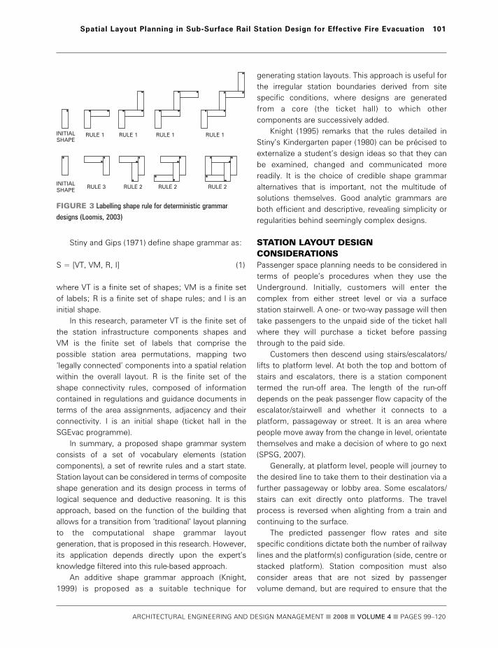
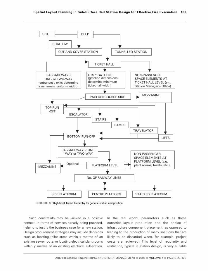
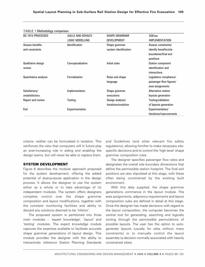
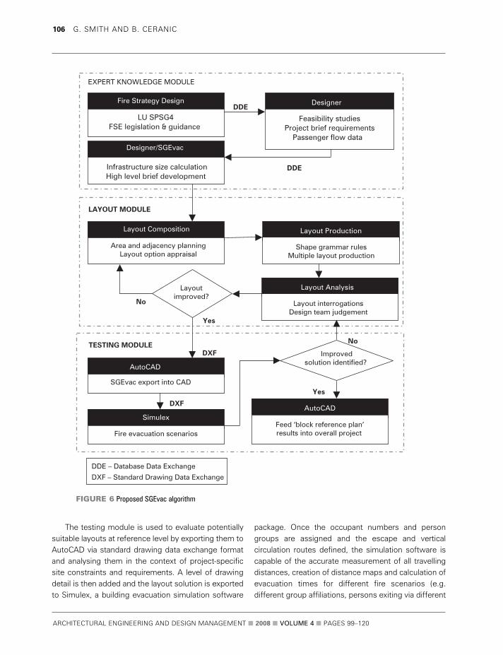
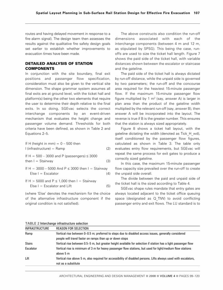
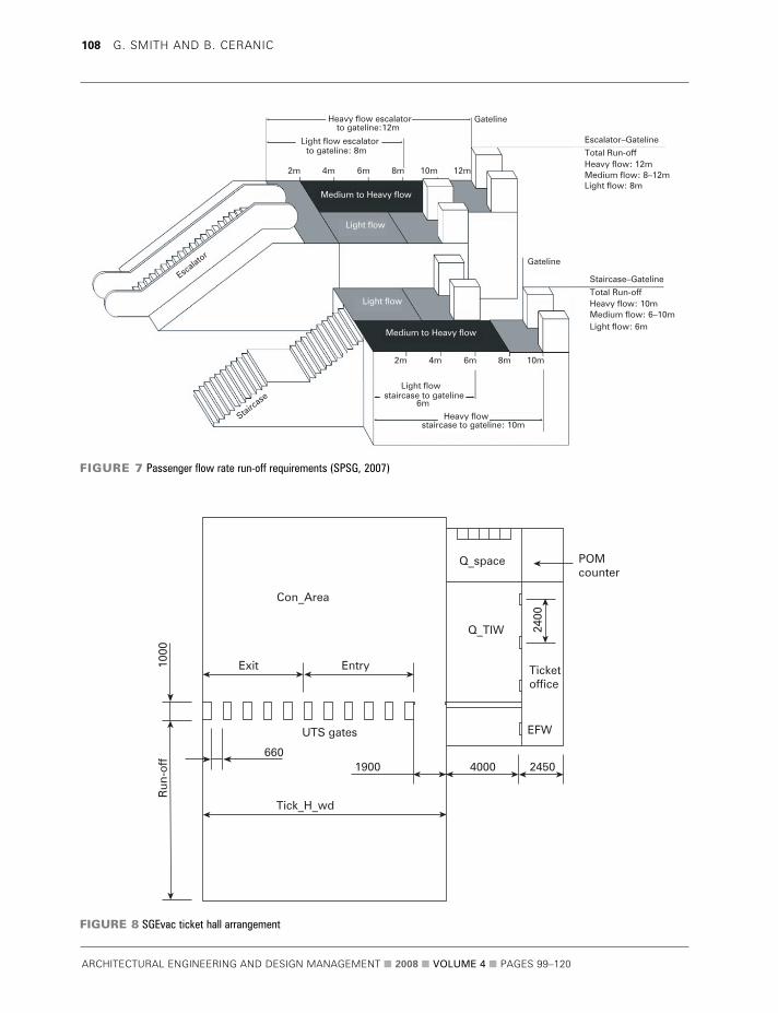
ARCHITECTURAL ENGINEERING AND DESIGN MANAGEMENT 2008 VOLUME 4 PAGES 99ndash120
108 G SMITH AND B CERANIC
Con_Area
Exit
UTS gates
6601900 2450
2400
EFW
Ticketoffice
POMcounter
4000
Tick_H_wd
1000
Run
-off
Entry
Q_space
Q_TIW
FIGURE 8 SGEvac ticket hall arrangement
Heavy flow escalator
Escalator
Staircase
Medium to Heavy flow
Medium to Heavy flow
Light flow escalator
Light flow
Heavy flow 12mMedium flow 8ndash12m
Light flow
Light flow 8m
Light flow 6m
Heavy flow
staircase to gateline
staircase to gateline 10m
Light flow
to gateline12mGateline
Gateline
EscalatorndashGateline
Total Run-off
Heavy flow 10mMedium flow 6ndash10m
StaircasendashGateline
Total Run-off
to gateline 8m
2m 4m 6m 8m 10m
2m 4m 6m
6m
8m 10m
12m
FIGURE 7 Passenger flow rate run-off requirements (SPSG 2007)
allow for 4 m (or a five-person queue) as shown inFigure 8 The overall gateline is defined by summingboth exit and entry gate numbers obtained from user-inputted passenger figures
The length of the ticket office interface with theticket hall is stipulated by the number of ticket issuingwindows (TIWs) plus excess fare windows (EFWs)TIWs always belong on the unpaid side of the tickethall and EFWs always on the paid side both forrevenue protection reasons This situation facilitates aprecise shape grammar labelling for the ticket officeto ticket hallqueue space connection
Passenger operated machine (POM) enclosures arenormally connected to the ticket hall ticket office andits own queue space (noted as Q_space in Figure 8)
To make shape rule specification manageable allstation areas are divided into groups arranged to suitthe most probable connection patterns in the stationTable 5 shows the group station managerrsquos officeexample with all other station components followingthe same concept
London Underground views its stations as largebasements (Weller 2007) and escape distances fromplatforms are based on agreed dispensations with theLondon Fire Brigade SGEvac respects thesedistances by placing restrictive labels on the platformso that they cannot be exceeded as demonstrated bythe example shown in Figure 9
SGEvac escape stair infrastructure may bepositioned up to 20 m from the end of platforms toavoid undesirable lsquodead endrsquo conditions The 45 mmaximum platform travel distance starts from thenearside junction of the two 33 m wide escapestaircases with the 45 m distance rule creating ashortfall in the platform centre of 34 m Generallylocating three interchange components (eg stairs
ARCHITECTURAL ENGINEERING AND DESIGN MANAGEMENT 2008 VOLUME 4 PAGES 99ndash120
Spatial Layout Planning in Sub-Surface Rail Station Design for Effective Fire Evacuation 109
TABLE 3 Gateline width calculationMETHOD WORKED EXAMPLE
Obtain peak hourly flow rate through Say 6500 peoplehr
ticket hall
Calculate 5-minute peak passenger flow 650012 = 541
Allowance for ticket rejection 541 + 20 = 561
Allowance for growth in use demand 561 x 110 = 617
Assume 125 people use each gate over
the 5-minute peak passenger flow period 617125 = 493
Round up gates to nearest whole number 5 gates required
TABLE 4 London Underground ticket hall gateline parametersregulations (SPSG 2007)EQUIPMENT DIMENSIONS (W X D) POSITIONARRANGEMENT
Combined manualequipment gate 1750 x 270 mm Height ndash 1300 mm Adjacent to ticket office Can include
1400 mm clear opening luggage facility
Manual gate ndash passenger 1750 x 270 mm Height ndash 1300 mm Adjacent to ticket office With more than 6
gateluggage port 900 mm ndash clearance and walkways in a single gateline or significant
outward opening interchange with mainline stations airport or
tourist traffic provide separate luggage chutes
Manual gate ndash single leaf 1394 mm Height ndash 1300 mm Beside the dedicated excess gates
with luggage port 695 mm clearance
Gateline attendance report 990 x 1240 mm Within the controlled zone but not necessarily
part of the gateline Usually close
Station control unit (SCU) 432 x 430 mm Should be installed within a secure enclosure
(which could be a ticket office) and also with
a clear view of the gates Controls and monitors
the station underground ticketing system
equipment
Manual emergency exit gates 1900 x 125 mm Adjacent to ticket office Add these gates rather
than adding extra UTS gates for evacuation
purposes
or escalators) at these distances will result incompliance with the Underground standards but itmay not always be possible (or practical for aninterchange situation) to procure such a layout
Lengths of station components are controlled bya range of criteria For the platform it is the length ofthe train vehicle for interchange components it isthe vertical height in the terms of the depth to theplatform level for passages it is the designated finalexit positions and the existing station areas alreadygenerated
Vector direction labels are underpinned by thepermissible union of compatible spaces two points ofcontact will be maintained so as not to restrict thewidth of connecting passenger areas This undueconstriction of passenger flow at the head of apassage also satisfies realistic construction practiceNon-passenger and ancillary area vector directions areas per project requirements and the successive areaadditions managed by the SGEvac rule groupings
To create alternative layouts SGEvac uses alsquorandomizersquo rule In this shape grammar rule initialstate infrastructure is generated as per guidelinesbut it can randomly change the location ofcomponent arrangements within the predefined
boundaries so that a number of possible alternativelayouts are produced The designs can then beinterrogated and ranked by their travelling distancesand against the qualitative functional logicstatements
The SGEvac design tool developed in this researchis based on a highly restrictive additive grammar ruleset due to SPSGrsquos prescriptive guidance and thenature of the layout planning problem As Grimsdaleand Chang (1996) argue many published grammarslack high-level reasoning during the iteration processsince they are often concerned with the developmentof shape grammar theories rather than their practicalapplications By contrast SGEvac being a practicalapplication has a complete set of primitive shapesonly possible to arrange in a certain way It thusprovides viable reference design layout compositionsbased on SPSG with further interventions possible bythe designer
SYSTEM DEVELOPMENT TO DATEThe SGEvac prototype is compiled within the Clanguage environment allowing for modular object-oriented programming (suitable for shape grammar)Figure 10 shows the main interface where the stationname and relevant LU fare zone are entered (whichimpacts on sizing infrastructure) as are the ticket halland platform depths the overall site boundaries andfinal exitsrsquo positions The peak passenger flow figuresover the relevant time interval of normally 3 hours arealso specified SGEvac is then capable of accuratelycalculating all passenger area infrastructure based onthe SPSG guidelines as already discussed
ARCHITECTURAL ENGINEERING AND DESIGN MANAGEMENT 2008 VOLUME 4 PAGES 99ndash120
110 G SMITH AND B CERANIC
TABLE 5 Station manager suite ndash shape rule connectionsELEMENT SHAPE RULE DESIGNATION CONNECTED COMPONENT GROUP ALLOCATION
Group station managerrsquos office SR_GSM_01 Ticket hall paid side GSM
SR_GSM_02 Ticket hall unpaid side
SR_GSM_03 GSM administration
SR_GSM_04 Duty station managerrsquos office
SR_GSM_05 Business managerrsquos office
SR_GSM_06 Administration
SR_GSM_07 Ticket office
SR_GSM_08 Police room
SR_GSM_09 Revenue protection examiner
SR_GSM_10 Interview room
140
Stair Stair
100 2020
4533
34
45
FIGURE 9 Platform escape distance SGEvac label restrictions
The history of auto-generated layouts is accessiblefrom this screen and the user is given the capabilityto delete and copy them (useful when minoralterations are required to produce an alternativelayout)
Shape labelling in the programme is multi-faceted which is necessary since many stationcomponents have various possible connections Anescalator for example may connect to a passagetravelator ramp escalator run-off stair run-off lift orthe ticket hall so all such connections need adding tothe component properties The SGEvac grouping ofcomponent interactions is accessed from menutoolbars that allow insertion of legislative compliantstation area connections as shown in Figure 11
Once the position and the depth of the ticket halland platform are specified the railway track is inserteddependent on the platform configuration The platformis the only possible connection to the track but thetrack can be positioned either side of platforms so thata side or centre (island) platform layout is possible
Non-passenger and ancillary areas are alsoselectable from the shape grammar library via property
windows for each station component eg the ticketoffice properties window as shown in Figure 12
Figure 13 shows examples of the layout modulestation components available in the SGEvacprogramme
Figure 14 shows the layout module interfaceInformation on the components (relative position inthe overall site layout and its absolute sizing) isdisplayed at the bottom of the screen once thecomponent is selected from the list In addition ameasurement bar (in metres) at the base of theinteractive design environment provides a sense ofscale for the designer
A checklist summarizes the station areas includedin the layout but a more detailed analysis is possiblevia a report function if required In addition to thisdetailed list a summary screen accessed from themain interface collates all specified components ineach generated layout This screen lists all passengernon-passenger and ancillary areas in their respectivecategories with infrastructure width data ofpassenger areas also summarized It also has anevacuation summary where the train frequency is
ARCHITECTURAL ENGINEERING AND DESIGN MANAGEMENT 2008 VOLUME 4 PAGES 99ndash120
Spatial Layout Planning in Sub-Surface Rail Station Design for Effective Fire Evacuation 111
FIGURE 10 SGEvac main interface
specified and the train evacuation load (taken as peaklsquorush hourrsquo loading) is displayed This section of thesummary screen is useful for input into Simulexwhere fire evacuation test runs of the building layoutcan be implemented
The lsquoshow hierarchyrsquo function in Figure 15 allowsdesign team members to view the progression ofdesigns by superimposing connecting lines betweenstation elements in the order of their compositionThis also serves as a safeguard against deleting
ARCHITECTURAL ENGINEERING AND DESIGN MANAGEMENT 2008 VOLUME 4 PAGES 99ndash120
112 G SMITH AND B CERANIC
FIGURE 12 SGEvac ticket office properties window
FIGURE 11 SGEvac properties window
components out of sequence that could lead to aninvalid solution
Once auto-generated layouts are complete withcorrectly sized and legitimately connected stationcomponents manual insertion of non-passenger areaswould then commence Upon completion thegenerated layout is transferred to AutoCAD via dxf fileformat as shown in Figure 16 Once in AutoCAD thelayout has a level of detail added by the designer suchas door openings passage connections fire escapeopenings etc so that passenger flows may beassessed It is then exported to Simulex for fireevacuation simulation analysis again via dxf file format
Simulex understands any voids as potentialcirculation routes treating the rest as solid andpermanent obstructions ie walls internal structuralelements permanent fixtures etc Since its solutionoperates in a two-dimensional environment for whatin effect is a three-dimensional problem the means
of vertical circulation (eg staircases) have to beestablished True lengths of staircases must bespecified based on the total length of all flights(sloping length) and the intermediate rests The fireexits need to be defined both in terms of theirlocation and width The links have to be establishedto define the point of the connection between thefloors and staircasesescalatorsramps The travellingdistance maps are then calculated type and numberof occupants specified building populated and theevacuation simulation performed
SYSTEM TESTING AND VALIDATIONKuligowski and Peacock (2005) define and recommendthe following ways of validating evacuation models
validation against code requirements validation against fire drills or other peoplersquos
movement experimentstrials
ARCHITECTURAL ENGINEERING AND DESIGN MANAGEMENT 2008 VOLUME 4 PAGES 99ndash120
Spatial Layout Planning in Sub-Surface Rail Station Design for Effective Fire Evacuation 113
Gateline Vertical
Platform Right
Stairs Horizontal Stairs Vertical
Travelator Vertical
Ticket Hall
BMOAdmin Reception
Platform Top Ram Up Bottom Vertical
Lift Passage Horizontal
FIGURE 13 Examples of SGEvac station components
ARCHITECTURAL ENGINEERING AND DESIGN MANAGEMENT 2008 VOLUME 4 PAGES 99ndash120
114 G SMITH AND B CERANIC
FIGURE 15 SGEvac hierarchy function
FIGURE 14 Layout module graphical user interface
validation against literature on past evacuationexperiments
validation against other models third-party validation
Furthermore Galea (1999) deconstructs the validationprocess into four main areas ndash component testingfunctional testing qualitative validation andquantitative validation This approach is more suitablefor models such as SGEvac than for those based oncompliance with code requirements and hence it isthe one adopted for the validation in this research
Component testing is regarded as testingcomputer code that drives the model checking forelementary errors Functional validation involveschecking that the model possesses the ability to
exhibit the range of capabilities required to performthe desired simulations Component testing andfunctional validation for SGEvac is carried outagainst code requirements insofar that allcalculations for infrastructure sizing are evaluatedmanually so that the method and answer are knownto be correct It uses the Simulex program to aid themodelling of people movement and to test thehypothesis of improvement to evacuation timesthus relying on Simulexrsquos own rigorous validationprocess Simulex has been used extensively inpractice as well as a validating model for otherevacuation softwares (Kuligowski and Peacock2005) SGEvac has gone through its initialcompletion and validation process with finalvalidation proposed for the end of the year
ARCHITECTURAL ENGINEERING AND DESIGN MANAGEMENT 2008 VOLUME 4 PAGES 99ndash120
Spatial Layout Planning in Sub-Surface Rail Station Design for Effective Fire Evacuation 115
FIGURE 16 Auto-generated SGEvac station layout export file for fire
evacuation simulation in Simulex
FIRE EVACUATION SIMULATION RESULTSThe considered lsquotrain on fire in stationrsquo scenario takesinto account the service interval of 333 minutes(based on 18 trains per hour) the crush capacity of afour-car train together with the number of peoplewaiting on the platform after cancellation of oneservice (ie after 666 minutes) On the oppositeplatform the evacuation load is taken to be thenormal boardingalighting load assuming nocancellations to services (50 of all boarders andalighters)
Evacuation load predictions were based on TfL2006 projected passenger flows with an averageflow of 36 peopleminute for boarders and 123peopleminute for boarders and alighters combinedThe train crush capacity was averaged at 165peoplecar The simulation also models evacuationfrom the ticket hall level to assess the impact ofdispersing crowds at peak times in this part of thestation From these figures the total evacuation loadwas calculated as follows
Platform 1 Boarders (36 x 666 min) = 240Train crush load (165 x 4) = 660
Platform 2 Boarders and alighters
(123 x 05 x 333 min) = 205Ticket hall = 470Total station evacuation load = 1575 people
The simulation results have been captured as imagesat 25 50 100 and 300 second intervals respectivelyfor both platform and ticket hall levels as shown inFigures 17 to 20
The provided means of escape follow LU SPSG4requirements insofar that the maximum travellingdistance on a platform to an exit is no more than 45 m (ie exits must be no more than 90 m apart) andthat the dead-end travelling distance is no more than20 m to an exit Hence each platform is provided withthree exits The MIPsrsquo (mobility impaired persons)means of escape is provided from both ends ofplatforms via emergency evacuation lifts Totalevacuation time (ie all people reaching an exit onticket hallground level) was 5 minutes and
24 seconds with the platform and train load clearedwithin 3 minutes and 5 seconds This is within therequirements to evacuate the platform and train loadwithin 4 minutes with all people reaching a fire-separated route within 6 minutes (the ticket hall is notclassed as a fire-separated route)
The performed simulation was based on theminimum travelling distance maps resulting in eachperson exiting via the nearest fire exit route Theaverage 10 second lsquotime to start to moversquo wasassigned to all occupants in order to accommodatefor real world people behaviour commonly reportedby fire evacuation research studies The boarders onthe end of both platforms (including most peoplefrom end carriages of the train) evacuated viastaircasesMIP lifts directly to the ground level pointof escape The boarders situated around the middleof platforms together with the people from the twomiddle carriages used the central escalators to reachticket hall fire exits Additionally some people fromthe end carriages and some staffretail unitcustomers used this route as means of escape
In this lsquotrain on fire in stationrsquo scenario it wasassumed that none of the escapes routes areunavailable due to maintenance However furtherevacuation studies will investigate possible scenarioswhere one of the escalator routes may be unavailabledue to maintenance reasons
FUTURE RESEARCHIntended future work will concentrate on the furtherconditioning developing and modelling of shapegrammar design rules based on the outcomes of thefinal system validation and LU expertsrsquo feedbackFurther research is proposed on the development ofa novel layout optimization approach based on theshape grammar rules to investigate the evacuation-related parametric improvements in subsurfacesurface railway station design (eg minimizingtravelling distances)
The fire safety strategy in terms of performance-based fire risk design is an important aspirationalaspect of SGEvac requiring further research andliaison with experts to determine how such variedcriteria could be allied with layout planning This isparticularly important where deviation from standardsoccurs Thus further development of the expert
ARCHITECTURAL ENGINEERING AND DESIGN MANAGEMENT 2008 VOLUME 4 PAGES 99ndash120
116 G SMITH AND B CERANIC
ARCHITECTURAL ENGINEERING AND DESIGN MANAGEMENT 2008 VOLUME 4 PAGES 99ndash120
Spatial Layout Planning in Sub-Surface Rail Station Design for Effective Fire Evacuation 117
FIGURE 17 Station evacuation after 25 seconds
FIGURE 18 Station evacuation after 50 seconds
ARCHITECTURAL ENGINEERING AND DESIGN MANAGEMENT 2008 VOLUME 4 PAGES 99ndash120
118 G SMITH AND B CERANIC
FIGURE 19 Station evacuation after 100 seconds
FIGURE 20 Station evacuation after 300 seconds
knowledge database would be required particularlyin the light of frequent changes to legislation
On a more practical note it could be beneficial todevelop the system on a stand-alone modular basislinked to each generated station component A list offire safety strategy objectives and functional logicstatements can then be specified for commonlyrecurring items (such as emergency lighting fire alarmdetectors sprinkler heads etc) and spaced accordingto the designerrsquos wishes or via shape rule formulation
Site constraint issues would also benefit fromfuture development as well as a move towardsdevelopment of the 3D shape grammar version Oncedevised other relevant 3D modelling systems such ascomputational fluid dynamics (CFD) smoke movementsoftware could be utilized in conjunction with SGEvac
CONCLUSIONSThe computer-aided modelling environment underdevelopment is intended to act as a layout planning aidfor those who practice in sub-surfacesurface railwaystation design The system under developmentcarefully considers London Underground StationPlanning Standards and Guidelines together withother relevant fire safety regulations that influenceoverall fire strategy design The proposed computer-aided design environment (SGEvac) is based on highlyrestrictive additive shape grammar rules driven by akernel of key passenger flow information to generatestation plan solutions
The major benefit to the design team is the ability toreview multiple layouts of accurately sized and correctlyplaced infrastructure at the reference or preliminarystage of the station layout planning design process Timeis hence saved regarding different option appraisals andquantitative testing using evacuation software shouldlead to a choice of more effective layouts in relation tomeans of escape travelling distances and improvementin the total evacuation times Modifications to layoutsshould be straightforward and there is scope toefficiently assess travelling distances and evacuationtimes for each of the considered alternatives comparedwith a lsquotraditionalrsquo approach
The proposed novel shape grammar approach ismost suited to new-build stations or largerefurbishment projects where more design flexibilityexists Sites with many site-specific constraints have
an array of predetermined parameters and will mostlikely benefit from the manual operation of SGEvac
Use in other rail systems due to recurringinfrastructure components and inherent functionallogic related to the laying out of the stationcomponents is also feasible provided that shapeconnections and shape rules are corrected to reflectthat countryrsquos legislative requirements
The potential for station layout improvementswith regard to emergency evacuation is an area thatmerits research especially in scenarios that concernthe safety of the general public and form a vital partof Londonrsquos transportation system Potential layoutimprovements could not only benefit evacuationsituations but also enhance the through-flow ofpeople during peak travelling periods
ACKNOWLEDGEMENTS The authors wish to express their gratitude to JacobsEngineering (UK) Ltd which has sponsored theresearch and to London Underground Ltd forproviding the design guidance that is reproduced inthis paper and for authorising the use of the stationplans London Underground has not reviewed thispaper and the content is solely the authorsrsquo work Mr Robert Hutchinson is also thanked for hiscomputer programming assistance
AUTHOR CONTACT DETAILSGGrraahhaamm SSmmiitthh (corresponding author) Senior Architectural
Technologist Jacobs (UK) Ltd Cardinal Square North Point
10 Nottingham Road Derby DE1 3QT UK Tel +44 (0)1332 234482
fax +44 (0)1332 344558 e-mail grahampsmithjacobscomBBoorriiss CCeerraanniicc Programme Leader for BScBA (Hons) Architectural
Programmes Room Number 105 Faculty of Arts Design and
Technology University of Derby Markeaton Street Derby DE22
3AW UK Tel +44 (0)1332 593136 e-mail bceranicderbyacuk
REFERENCES BS 7974 2001 Application of Fire Safety Engineering Principles to the
Design of Buildings London BSI
Cha MY and Gero JS 1999 Style Learning Inductive Generalisation of
Architectural Shape Patterns Paichai University and Sydney University
co-paper
ARCHITECTURAL ENGINEERING AND DESIGN MANAGEMENT 2008 VOLUME 4 PAGES 99ndash120
Spatial Layout Planning in Sub-Surface Rail Station Design for Effective Fire Evacuation 119
Chase SC 1996 lsquoUsing logic to specify shapes and spatial relations in
design grammarsrsquo in Workshop notes Grammatical Design Fourth
International Conference on Artificial Intelligence in Design Stanford
University US June
Department of the Environment 1996 Design Principles of Fire Safety
London The Stationery Office Books
Flemming U 1987 lsquoMore than the sum of its parts the grammar of
Queen Anne housesrsquo in Environment and Planning B Planning and
Design 14 323ndash350
Fruin JJ 1971 Pedestrian Planning and Design New York Metropolitan
Association of Urban Designers and Environmental Planners
Galea ER 1999 lsquoA general approach to validating evacuation models with
an application to EXODUSrsquo in Journal of Fire Sciences 16 414ndash436
Galle P and Kovacs LB 1992 lsquoThe logic of worms a study in
architectural knowledge representationrsquo in Environment and Planning B
Planning and Design 19 5ndash31
Garling T Lindberg E and Mantyla T 1983 lsquoOrientation in buildings ndash
effects of familiarity visual access and orientation aidsrsquo in Journal of
Applied Psychology 68(1) 177ndash186
Grimsdale RL and Chang CW 1996 lsquoThe layout design language A
technique for generating layout plansrsquo in Computer Graphics Forum
15(2) 97ndash106
Heskestad AW 1999 lsquoPerformance in smoke of way guidance systemsrsquo
in Fire and Materials 23(6) 375ndash381
Knight T 1995 lsquoConstructive symmetryrsquo in Environment and Planning B
Planning and Design 22 419ndash450
Knight TW 1999 lsquoShape grammars six typesrsquo in Environment and
Planning B Planning and Design 26 15ndash31
Kuligowski ED and Peacock RD 2005 A Review of Building Evacuation
Models Technical Note 1471 National Institute of Standards and
Technology (NIST) Technology Administration US Department of
Commerce
Li A I-Kang 2003 lsquoThe Yingzao fashi in the information agersquo conference
paper for the Beaux-Arts Paul Philippe Cret and Twentieth Century
Architecture in China The University of Pennsylvania October
Liew H 2003 lsquoSGML ndash A shape grammar meta-languagersquo in Digital
Design 21st eCAADe Conference Proceedings Graz Austria September
639ndash648
Loomis B 2003 lsquoA note on generative design techniques SGGA a user
driven genetic algorithm for evolving non-deterministic shape grammarsrsquo
working paper Massachusetts Institute of Technology (MIT)
Magnusson SE Drysdale DD Fitzgerald RW Mowrer F
Quintiere JG Williamson RB and Zalosh RG 1995
lsquoA proposal for a model curriculum in fire safety engineeringrsquo
in Fire Safety Journal 25 9ndash10
Smith G Ceranic B and Fryer C 2003 lsquoDevelopment of CAD
environment for spatial layout optimisation in sub-surfacesurface rail
station designrsquo in Proceedings of International BIAT Conference The
British Museum London January 2003
SPSG 2007 London Underground Station Planning Standards and
Guidelines SPSG4 (1ndash371) London
Stiny G and Gips J 1971 lsquoShape grammars and the generative
specification of painting and sculpturersquo in Information Processing 71
1460ndash1465
Stiny G 1977 lsquoIce-ray a note on the generation of Chinese lattice
designsrsquo in Environment and Planning B Planning and Design 4 89ndash98
Stiny G 1980 lsquoKindergarten grammars designing with Froebelrsquos building
giftsrsquo in Environment and Planning B 3 409ndash462
Tapia M 1999 lsquoA visual implementation of a shape grammar systemrsquo in
Environment and Planning B Planning and Design 26(1) 59ndash73
Transport for London 2007 Tube Carries One Billion Passengers for First
Time wwwtflgovukcorporatemedianewscentre4770aspx
(accessed 24 March 2008)
Weller M 2007 London Underground private correspondence
ARCHITECTURAL ENGINEERING AND DESIGN MANAGEMENT 2008 VOLUME 4 PAGES 99ndash120
120 G SMITH AND B CERANIC
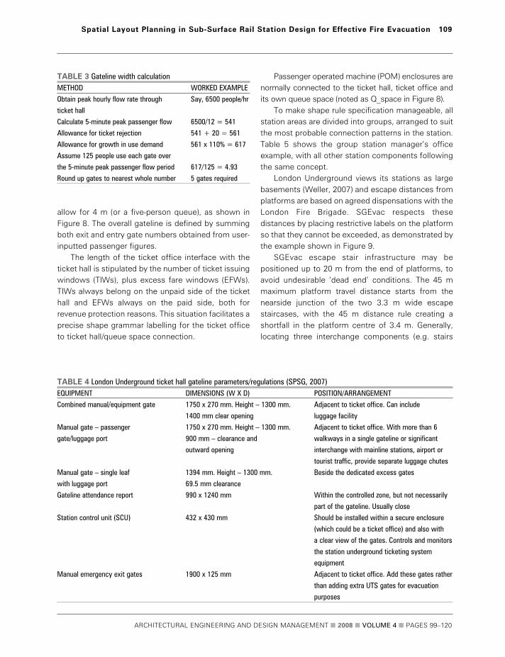
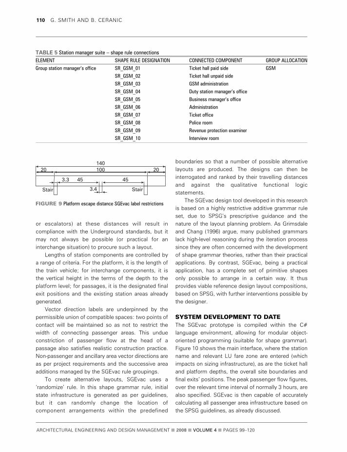
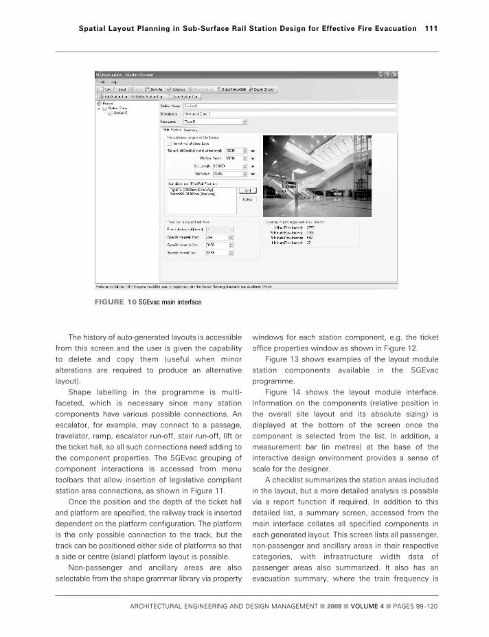
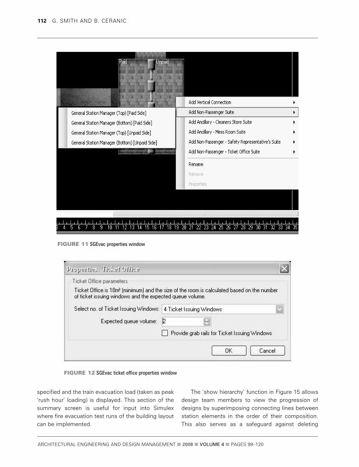
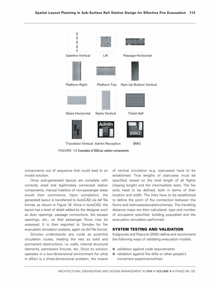
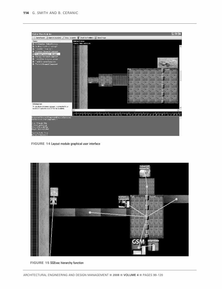
ARCHITECTURAL ENGINEERING AND DESIGN MANAGEMENT 2008 VOLUME 4 PAGES 99ndash120
114 G SMITH AND B CERANIC
FIGURE 15 SGEvac hierarchy function
FIGURE 14 Layout module graphical user interface
validation against literature on past evacuationexperiments
validation against other models third-party validation
Furthermore Galea (1999) deconstructs the validationprocess into four main areas ndash component testingfunctional testing qualitative validation andquantitative validation This approach is more suitablefor models such as SGEvac than for those based oncompliance with code requirements and hence it isthe one adopted for the validation in this research
Component testing is regarded as testingcomputer code that drives the model checking forelementary errors Functional validation involveschecking that the model possesses the ability to
exhibit the range of capabilities required to performthe desired simulations Component testing andfunctional validation for SGEvac is carried outagainst code requirements insofar that allcalculations for infrastructure sizing are evaluatedmanually so that the method and answer are knownto be correct It uses the Simulex program to aid themodelling of people movement and to test thehypothesis of improvement to evacuation timesthus relying on Simulexrsquos own rigorous validationprocess Simulex has been used extensively inpractice as well as a validating model for otherevacuation softwares (Kuligowski and Peacock2005) SGEvac has gone through its initialcompletion and validation process with finalvalidation proposed for the end of the year
ARCHITECTURAL ENGINEERING AND DESIGN MANAGEMENT 2008 VOLUME 4 PAGES 99ndash120
Spatial Layout Planning in Sub-Surface Rail Station Design for Effective Fire Evacuation 115
FIGURE 16 Auto-generated SGEvac station layout export file for fire
evacuation simulation in Simulex
FIRE EVACUATION SIMULATION RESULTSThe considered lsquotrain on fire in stationrsquo scenario takesinto account the service interval of 333 minutes(based on 18 trains per hour) the crush capacity of afour-car train together with the number of peoplewaiting on the platform after cancellation of oneservice (ie after 666 minutes) On the oppositeplatform the evacuation load is taken to be thenormal boardingalighting load assuming nocancellations to services (50 of all boarders andalighters)
Evacuation load predictions were based on TfL2006 projected passenger flows with an averageflow of 36 peopleminute for boarders and 123peopleminute for boarders and alighters combinedThe train crush capacity was averaged at 165peoplecar The simulation also models evacuationfrom the ticket hall level to assess the impact ofdispersing crowds at peak times in this part of thestation From these figures the total evacuation loadwas calculated as follows
Platform 1 Boarders (36 x 666 min) = 240Train crush load (165 x 4) = 660
Platform 2 Boarders and alighters
(123 x 05 x 333 min) = 205Ticket hall = 470Total station evacuation load = 1575 people
The simulation results have been captured as imagesat 25 50 100 and 300 second intervals respectivelyfor both platform and ticket hall levels as shown inFigures 17 to 20
The provided means of escape follow LU SPSG4requirements insofar that the maximum travellingdistance on a platform to an exit is no more than 45 m (ie exits must be no more than 90 m apart) andthat the dead-end travelling distance is no more than20 m to an exit Hence each platform is provided withthree exits The MIPsrsquo (mobility impaired persons)means of escape is provided from both ends ofplatforms via emergency evacuation lifts Totalevacuation time (ie all people reaching an exit onticket hallground level) was 5 minutes and
24 seconds with the platform and train load clearedwithin 3 minutes and 5 seconds This is within therequirements to evacuate the platform and train loadwithin 4 minutes with all people reaching a fire-separated route within 6 minutes (the ticket hall is notclassed as a fire-separated route)
The performed simulation was based on theminimum travelling distance maps resulting in eachperson exiting via the nearest fire exit route Theaverage 10 second lsquotime to start to moversquo wasassigned to all occupants in order to accommodatefor real world people behaviour commonly reportedby fire evacuation research studies The boarders onthe end of both platforms (including most peoplefrom end carriages of the train) evacuated viastaircasesMIP lifts directly to the ground level pointof escape The boarders situated around the middleof platforms together with the people from the twomiddle carriages used the central escalators to reachticket hall fire exits Additionally some people fromthe end carriages and some staffretail unitcustomers used this route as means of escape
In this lsquotrain on fire in stationrsquo scenario it wasassumed that none of the escapes routes areunavailable due to maintenance However furtherevacuation studies will investigate possible scenarioswhere one of the escalator routes may be unavailabledue to maintenance reasons
FUTURE RESEARCHIntended future work will concentrate on the furtherconditioning developing and modelling of shapegrammar design rules based on the outcomes of thefinal system validation and LU expertsrsquo feedbackFurther research is proposed on the development ofa novel layout optimization approach based on theshape grammar rules to investigate the evacuation-related parametric improvements in subsurfacesurface railway station design (eg minimizingtravelling distances)
The fire safety strategy in terms of performance-based fire risk design is an important aspirationalaspect of SGEvac requiring further research andliaison with experts to determine how such variedcriteria could be allied with layout planning This isparticularly important where deviation from standardsoccurs Thus further development of the expert
ARCHITECTURAL ENGINEERING AND DESIGN MANAGEMENT 2008 VOLUME 4 PAGES 99ndash120
116 G SMITH AND B CERANIC
ARCHITECTURAL ENGINEERING AND DESIGN MANAGEMENT 2008 VOLUME 4 PAGES 99ndash120
Spatial Layout Planning in Sub-Surface Rail Station Design for Effective Fire Evacuation 117
FIGURE 17 Station evacuation after 25 seconds
FIGURE 18 Station evacuation after 50 seconds
ARCHITECTURAL ENGINEERING AND DESIGN MANAGEMENT 2008 VOLUME 4 PAGES 99ndash120
118 G SMITH AND B CERANIC
FIGURE 19 Station evacuation after 100 seconds
FIGURE 20 Station evacuation after 300 seconds
knowledge database would be required particularlyin the light of frequent changes to legislation
On a more practical note it could be beneficial todevelop the system on a stand-alone modular basislinked to each generated station component A list offire safety strategy objectives and functional logicstatements can then be specified for commonlyrecurring items (such as emergency lighting fire alarmdetectors sprinkler heads etc) and spaced accordingto the designerrsquos wishes or via shape rule formulation
Site constraint issues would also benefit fromfuture development as well as a move towardsdevelopment of the 3D shape grammar version Oncedevised other relevant 3D modelling systems such ascomputational fluid dynamics (CFD) smoke movementsoftware could be utilized in conjunction with SGEvac
CONCLUSIONSThe computer-aided modelling environment underdevelopment is intended to act as a layout planning aidfor those who practice in sub-surfacesurface railwaystation design The system under developmentcarefully considers London Underground StationPlanning Standards and Guidelines together withother relevant fire safety regulations that influenceoverall fire strategy design The proposed computer-aided design environment (SGEvac) is based on highlyrestrictive additive shape grammar rules driven by akernel of key passenger flow information to generatestation plan solutions
The major benefit to the design team is the ability toreview multiple layouts of accurately sized and correctlyplaced infrastructure at the reference or preliminarystage of the station layout planning design process Timeis hence saved regarding different option appraisals andquantitative testing using evacuation software shouldlead to a choice of more effective layouts in relation tomeans of escape travelling distances and improvementin the total evacuation times Modifications to layoutsshould be straightforward and there is scope toefficiently assess travelling distances and evacuationtimes for each of the considered alternatives comparedwith a lsquotraditionalrsquo approach
The proposed novel shape grammar approach ismost suited to new-build stations or largerefurbishment projects where more design flexibilityexists Sites with many site-specific constraints have
an array of predetermined parameters and will mostlikely benefit from the manual operation of SGEvac
Use in other rail systems due to recurringinfrastructure components and inherent functionallogic related to the laying out of the stationcomponents is also feasible provided that shapeconnections and shape rules are corrected to reflectthat countryrsquos legislative requirements
The potential for station layout improvementswith regard to emergency evacuation is an area thatmerits research especially in scenarios that concernthe safety of the general public and form a vital partof Londonrsquos transportation system Potential layoutimprovements could not only benefit evacuationsituations but also enhance the through-flow ofpeople during peak travelling periods
ACKNOWLEDGEMENTS The authors wish to express their gratitude to JacobsEngineering (UK) Ltd which has sponsored theresearch and to London Underground Ltd forproviding the design guidance that is reproduced inthis paper and for authorising the use of the stationplans London Underground has not reviewed thispaper and the content is solely the authorsrsquo work Mr Robert Hutchinson is also thanked for hiscomputer programming assistance
AUTHOR CONTACT DETAILSGGrraahhaamm SSmmiitthh (corresponding author) Senior Architectural
Technologist Jacobs (UK) Ltd Cardinal Square North Point
10 Nottingham Road Derby DE1 3QT UK Tel +44 (0)1332 234482
fax +44 (0)1332 344558 e-mail grahampsmithjacobscomBBoorriiss CCeerraanniicc Programme Leader for BScBA (Hons) Architectural
Programmes Room Number 105 Faculty of Arts Design and
Technology University of Derby Markeaton Street Derby DE22
3AW UK Tel +44 (0)1332 593136 e-mail bceranicderbyacuk
REFERENCES BS 7974 2001 Application of Fire Safety Engineering Principles to the
Design of Buildings London BSI
Cha MY and Gero JS 1999 Style Learning Inductive Generalisation of
Architectural Shape Patterns Paichai University and Sydney University
co-paper
ARCHITECTURAL ENGINEERING AND DESIGN MANAGEMENT 2008 VOLUME 4 PAGES 99ndash120
Spatial Layout Planning in Sub-Surface Rail Station Design for Effective Fire Evacuation 119
Chase SC 1996 lsquoUsing logic to specify shapes and spatial relations in
design grammarsrsquo in Workshop notes Grammatical Design Fourth
International Conference on Artificial Intelligence in Design Stanford
University US June
Department of the Environment 1996 Design Principles of Fire Safety
London The Stationery Office Books
Flemming U 1987 lsquoMore than the sum of its parts the grammar of
Queen Anne housesrsquo in Environment and Planning B Planning and
Design 14 323ndash350
Fruin JJ 1971 Pedestrian Planning and Design New York Metropolitan
Association of Urban Designers and Environmental Planners
Galea ER 1999 lsquoA general approach to validating evacuation models with
an application to EXODUSrsquo in Journal of Fire Sciences 16 414ndash436
Galle P and Kovacs LB 1992 lsquoThe logic of worms a study in
architectural knowledge representationrsquo in Environment and Planning B
Planning and Design 19 5ndash31
Garling T Lindberg E and Mantyla T 1983 lsquoOrientation in buildings ndash
effects of familiarity visual access and orientation aidsrsquo in Journal of
Applied Psychology 68(1) 177ndash186
Grimsdale RL and Chang CW 1996 lsquoThe layout design language A
technique for generating layout plansrsquo in Computer Graphics Forum
15(2) 97ndash106
Heskestad AW 1999 lsquoPerformance in smoke of way guidance systemsrsquo
in Fire and Materials 23(6) 375ndash381
Knight T 1995 lsquoConstructive symmetryrsquo in Environment and Planning B
Planning and Design 22 419ndash450
Knight TW 1999 lsquoShape grammars six typesrsquo in Environment and
Planning B Planning and Design 26 15ndash31
Kuligowski ED and Peacock RD 2005 A Review of Building Evacuation
Models Technical Note 1471 National Institute of Standards and
Technology (NIST) Technology Administration US Department of
Commerce
Li A I-Kang 2003 lsquoThe Yingzao fashi in the information agersquo conference
paper for the Beaux-Arts Paul Philippe Cret and Twentieth Century
Architecture in China The University of Pennsylvania October
Liew H 2003 lsquoSGML ndash A shape grammar meta-languagersquo in Digital
Design 21st eCAADe Conference Proceedings Graz Austria September
639ndash648
Loomis B 2003 lsquoA note on generative design techniques SGGA a user
driven genetic algorithm for evolving non-deterministic shape grammarsrsquo
working paper Massachusetts Institute of Technology (MIT)
Magnusson SE Drysdale DD Fitzgerald RW Mowrer F
Quintiere JG Williamson RB and Zalosh RG 1995
lsquoA proposal for a model curriculum in fire safety engineeringrsquo
in Fire Safety Journal 25 9ndash10
Smith G Ceranic B and Fryer C 2003 lsquoDevelopment of CAD
environment for spatial layout optimisation in sub-surfacesurface rail
station designrsquo in Proceedings of International BIAT Conference The
British Museum London January 2003
SPSG 2007 London Underground Station Planning Standards and
Guidelines SPSG4 (1ndash371) London
Stiny G and Gips J 1971 lsquoShape grammars and the generative
specification of painting and sculpturersquo in Information Processing 71
1460ndash1465
Stiny G 1977 lsquoIce-ray a note on the generation of Chinese lattice
designsrsquo in Environment and Planning B Planning and Design 4 89ndash98
Stiny G 1980 lsquoKindergarten grammars designing with Froebelrsquos building
giftsrsquo in Environment and Planning B 3 409ndash462
Tapia M 1999 lsquoA visual implementation of a shape grammar systemrsquo in
Environment and Planning B Planning and Design 26(1) 59ndash73
Transport for London 2007 Tube Carries One Billion Passengers for First
Time wwwtflgovukcorporatemedianewscentre4770aspx
(accessed 24 March 2008)
Weller M 2007 London Underground private correspondence
ARCHITECTURAL ENGINEERING AND DESIGN MANAGEMENT 2008 VOLUME 4 PAGES 99ndash120
120 G SMITH AND B CERANIC
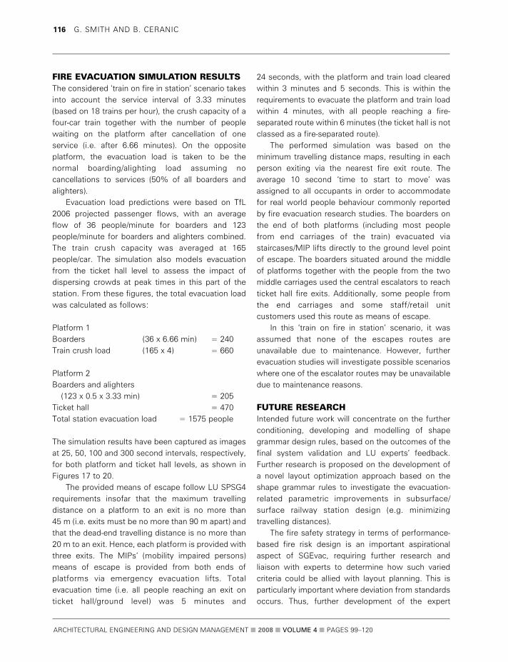

ARCHITECTURAL ENGINEERING AND DESIGN MANAGEMENT 2008 VOLUME 4 PAGES 99ndash120
Spatial Layout Planning in Sub-Surface Rail Station Design for Effective Fire Evacuation 117
FIGURE 17 Station evacuation after 25 seconds
FIGURE 18 Station evacuation after 50 seconds
ARCHITECTURAL ENGINEERING AND DESIGN MANAGEMENT 2008 VOLUME 4 PAGES 99ndash120
118 G SMITH AND B CERANIC
FIGURE 19 Station evacuation after 100 seconds
FIGURE 20 Station evacuation after 300 seconds
knowledge database would be required particularlyin the light of frequent changes to legislation
On a more practical note it could be beneficial todevelop the system on a stand-alone modular basislinked to each generated station component A list offire safety strategy objectives and functional logicstatements can then be specified for commonlyrecurring items (such as emergency lighting fire alarmdetectors sprinkler heads etc) and spaced accordingto the designerrsquos wishes or via shape rule formulation
Site constraint issues would also benefit fromfuture development as well as a move towardsdevelopment of the 3D shape grammar version Oncedevised other relevant 3D modelling systems such ascomputational fluid dynamics (CFD) smoke movementsoftware could be utilized in conjunction with SGEvac
CONCLUSIONSThe computer-aided modelling environment underdevelopment is intended to act as a layout planning aidfor those who practice in sub-surfacesurface railwaystation design The system under developmentcarefully considers London Underground StationPlanning Standards and Guidelines together withother relevant fire safety regulations that influenceoverall fire strategy design The proposed computer-aided design environment (SGEvac) is based on highlyrestrictive additive shape grammar rules driven by akernel of key passenger flow information to generatestation plan solutions
The major benefit to the design team is the ability toreview multiple layouts of accurately sized and correctlyplaced infrastructure at the reference or preliminarystage of the station layout planning design process Timeis hence saved regarding different option appraisals andquantitative testing using evacuation software shouldlead to a choice of more effective layouts in relation tomeans of escape travelling distances and improvementin the total evacuation times Modifications to layoutsshould be straightforward and there is scope toefficiently assess travelling distances and evacuationtimes for each of the considered alternatives comparedwith a lsquotraditionalrsquo approach
The proposed novel shape grammar approach ismost suited to new-build stations or largerefurbishment projects where more design flexibilityexists Sites with many site-specific constraints have
an array of predetermined parameters and will mostlikely benefit from the manual operation of SGEvac
Use in other rail systems due to recurringinfrastructure components and inherent functionallogic related to the laying out of the stationcomponents is also feasible provided that shapeconnections and shape rules are corrected to reflectthat countryrsquos legislative requirements
The potential for station layout improvementswith regard to emergency evacuation is an area thatmerits research especially in scenarios that concernthe safety of the general public and form a vital partof Londonrsquos transportation system Potential layoutimprovements could not only benefit evacuationsituations but also enhance the through-flow ofpeople during peak travelling periods
ACKNOWLEDGEMENTS The authors wish to express their gratitude to JacobsEngineering (UK) Ltd which has sponsored theresearch and to London Underground Ltd forproviding the design guidance that is reproduced inthis paper and for authorising the use of the stationplans London Underground has not reviewed thispaper and the content is solely the authorsrsquo work Mr Robert Hutchinson is also thanked for hiscomputer programming assistance
AUTHOR CONTACT DETAILSGGrraahhaamm SSmmiitthh (corresponding author) Senior Architectural
Technologist Jacobs (UK) Ltd Cardinal Square North Point
10 Nottingham Road Derby DE1 3QT UK Tel +44 (0)1332 234482
fax +44 (0)1332 344558 e-mail grahampsmithjacobscomBBoorriiss CCeerraanniicc Programme Leader for BScBA (Hons) Architectural
Programmes Room Number 105 Faculty of Arts Design and
Technology University of Derby Markeaton Street Derby DE22
3AW UK Tel +44 (0)1332 593136 e-mail bceranicderbyacuk
REFERENCES BS 7974 2001 Application of Fire Safety Engineering Principles to the
Design of Buildings London BSI
Cha MY and Gero JS 1999 Style Learning Inductive Generalisation of
Architectural Shape Patterns Paichai University and Sydney University
co-paper
ARCHITECTURAL ENGINEERING AND DESIGN MANAGEMENT 2008 VOLUME 4 PAGES 99ndash120
Spatial Layout Planning in Sub-Surface Rail Station Design for Effective Fire Evacuation 119
Chase SC 1996 lsquoUsing logic to specify shapes and spatial relations in
design grammarsrsquo in Workshop notes Grammatical Design Fourth
International Conference on Artificial Intelligence in Design Stanford
University US June
Department of the Environment 1996 Design Principles of Fire Safety
London The Stationery Office Books
Flemming U 1987 lsquoMore than the sum of its parts the grammar of
Queen Anne housesrsquo in Environment and Planning B Planning and
Design 14 323ndash350
Fruin JJ 1971 Pedestrian Planning and Design New York Metropolitan
Association of Urban Designers and Environmental Planners
Galea ER 1999 lsquoA general approach to validating evacuation models with
an application to EXODUSrsquo in Journal of Fire Sciences 16 414ndash436
Galle P and Kovacs LB 1992 lsquoThe logic of worms a study in
architectural knowledge representationrsquo in Environment and Planning B
Planning and Design 19 5ndash31
Garling T Lindberg E and Mantyla T 1983 lsquoOrientation in buildings ndash
effects of familiarity visual access and orientation aidsrsquo in Journal of
Applied Psychology 68(1) 177ndash186
Grimsdale RL and Chang CW 1996 lsquoThe layout design language A
technique for generating layout plansrsquo in Computer Graphics Forum
15(2) 97ndash106
Heskestad AW 1999 lsquoPerformance in smoke of way guidance systemsrsquo
in Fire and Materials 23(6) 375ndash381
Knight T 1995 lsquoConstructive symmetryrsquo in Environment and Planning B
Planning and Design 22 419ndash450
Knight TW 1999 lsquoShape grammars six typesrsquo in Environment and
Planning B Planning and Design 26 15ndash31
Kuligowski ED and Peacock RD 2005 A Review of Building Evacuation
Models Technical Note 1471 National Institute of Standards and
Technology (NIST) Technology Administration US Department of
Commerce
Li A I-Kang 2003 lsquoThe Yingzao fashi in the information agersquo conference
paper for the Beaux-Arts Paul Philippe Cret and Twentieth Century
Architecture in China The University of Pennsylvania October
Liew H 2003 lsquoSGML ndash A shape grammar meta-languagersquo in Digital
Design 21st eCAADe Conference Proceedings Graz Austria September
639ndash648
Loomis B 2003 lsquoA note on generative design techniques SGGA a user
driven genetic algorithm for evolving non-deterministic shape grammarsrsquo
working paper Massachusetts Institute of Technology (MIT)
Magnusson SE Drysdale DD Fitzgerald RW Mowrer F
Quintiere JG Williamson RB and Zalosh RG 1995
lsquoA proposal for a model curriculum in fire safety engineeringrsquo
in Fire Safety Journal 25 9ndash10
Smith G Ceranic B and Fryer C 2003 lsquoDevelopment of CAD
environment for spatial layout optimisation in sub-surfacesurface rail
station designrsquo in Proceedings of International BIAT Conference The
British Museum London January 2003
SPSG 2007 London Underground Station Planning Standards and
Guidelines SPSG4 (1ndash371) London
Stiny G and Gips J 1971 lsquoShape grammars and the generative
specification of painting and sculpturersquo in Information Processing 71
1460ndash1465
Stiny G 1977 lsquoIce-ray a note on the generation of Chinese lattice
designsrsquo in Environment and Planning B Planning and Design 4 89ndash98
Stiny G 1980 lsquoKindergarten grammars designing with Froebelrsquos building
giftsrsquo in Environment and Planning B 3 409ndash462
Tapia M 1999 lsquoA visual implementation of a shape grammar systemrsquo in
Environment and Planning B Planning and Design 26(1) 59ndash73
Transport for London 2007 Tube Carries One Billion Passengers for First
Time wwwtflgovukcorporatemedianewscentre4770aspx
(accessed 24 March 2008)
Weller M 2007 London Underground private correspondence
ARCHITECTURAL ENGINEERING AND DESIGN MANAGEMENT 2008 VOLUME 4 PAGES 99ndash120
120 G SMITH AND B CERANIC
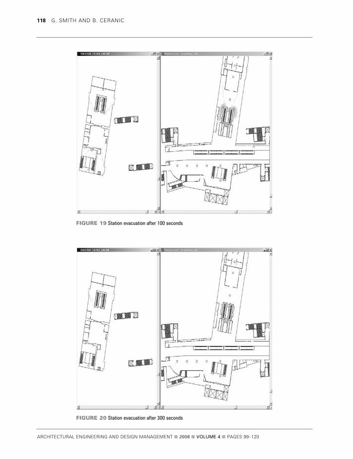
ARCHITECTURAL ENGINEERING AND DESIGN MANAGEMENT 2008 VOLUME 4 PAGES 99ndash120
118 G SMITH AND B CERANIC
FIGURE 19 Station evacuation after 100 seconds
FIGURE 20 Station evacuation after 300 seconds
knowledge database would be required particularlyin the light of frequent changes to legislation
On a more practical note it could be beneficial todevelop the system on a stand-alone modular basislinked to each generated station component A list offire safety strategy objectives and functional logicstatements can then be specified for commonlyrecurring items (such as emergency lighting fire alarmdetectors sprinkler heads etc) and spaced accordingto the designerrsquos wishes or via shape rule formulation
Site constraint issues would also benefit fromfuture development as well as a move towardsdevelopment of the 3D shape grammar version Oncedevised other relevant 3D modelling systems such ascomputational fluid dynamics (CFD) smoke movementsoftware could be utilized in conjunction with SGEvac
CONCLUSIONSThe computer-aided modelling environment underdevelopment is intended to act as a layout planning aidfor those who practice in sub-surfacesurface railwaystation design The system under developmentcarefully considers London Underground StationPlanning Standards and Guidelines together withother relevant fire safety regulations that influenceoverall fire strategy design The proposed computer-aided design environment (SGEvac) is based on highlyrestrictive additive shape grammar rules driven by akernel of key passenger flow information to generatestation plan solutions
The major benefit to the design team is the ability toreview multiple layouts of accurately sized and correctlyplaced infrastructure at the reference or preliminarystage of the station layout planning design process Timeis hence saved regarding different option appraisals andquantitative testing using evacuation software shouldlead to a choice of more effective layouts in relation tomeans of escape travelling distances and improvementin the total evacuation times Modifications to layoutsshould be straightforward and there is scope toefficiently assess travelling distances and evacuationtimes for each of the considered alternatives comparedwith a lsquotraditionalrsquo approach
The proposed novel shape grammar approach ismost suited to new-build stations or largerefurbishment projects where more design flexibilityexists Sites with many site-specific constraints have
an array of predetermined parameters and will mostlikely benefit from the manual operation of SGEvac
Use in other rail systems due to recurringinfrastructure components and inherent functionallogic related to the laying out of the stationcomponents is also feasible provided that shapeconnections and shape rules are corrected to reflectthat countryrsquos legislative requirements
The potential for station layout improvementswith regard to emergency evacuation is an area thatmerits research especially in scenarios that concernthe safety of the general public and form a vital partof Londonrsquos transportation system Potential layoutimprovements could not only benefit evacuationsituations but also enhance the through-flow ofpeople during peak travelling periods
ACKNOWLEDGEMENTS The authors wish to express their gratitude to JacobsEngineering (UK) Ltd which has sponsored theresearch and to London Underground Ltd forproviding the design guidance that is reproduced inthis paper and for authorising the use of the stationplans London Underground has not reviewed thispaper and the content is solely the authorsrsquo work Mr Robert Hutchinson is also thanked for hiscomputer programming assistance
AUTHOR CONTACT DETAILSGGrraahhaamm SSmmiitthh (corresponding author) Senior Architectural
Technologist Jacobs (UK) Ltd Cardinal Square North Point
10 Nottingham Road Derby DE1 3QT UK Tel +44 (0)1332 234482
fax +44 (0)1332 344558 e-mail grahampsmithjacobscomBBoorriiss CCeerraanniicc Programme Leader for BScBA (Hons) Architectural
Programmes Room Number 105 Faculty of Arts Design and
Technology University of Derby Markeaton Street Derby DE22
3AW UK Tel +44 (0)1332 593136 e-mail bceranicderbyacuk
REFERENCES BS 7974 2001 Application of Fire Safety Engineering Principles to the
Design of Buildings London BSI
Cha MY and Gero JS 1999 Style Learning Inductive Generalisation of
Architectural Shape Patterns Paichai University and Sydney University
co-paper
ARCHITECTURAL ENGINEERING AND DESIGN MANAGEMENT 2008 VOLUME 4 PAGES 99ndash120
Spatial Layout Planning in Sub-Surface Rail Station Design for Effective Fire Evacuation 119
Chase SC 1996 lsquoUsing logic to specify shapes and spatial relations in
design grammarsrsquo in Workshop notes Grammatical Design Fourth
International Conference on Artificial Intelligence in Design Stanford
University US June
Department of the Environment 1996 Design Principles of Fire Safety
London The Stationery Office Books
Flemming U 1987 lsquoMore than the sum of its parts the grammar of
Queen Anne housesrsquo in Environment and Planning B Planning and
Design 14 323ndash350
Fruin JJ 1971 Pedestrian Planning and Design New York Metropolitan
Association of Urban Designers and Environmental Planners
Galea ER 1999 lsquoA general approach to validating evacuation models with
an application to EXODUSrsquo in Journal of Fire Sciences 16 414ndash436
Galle P and Kovacs LB 1992 lsquoThe logic of worms a study in
architectural knowledge representationrsquo in Environment and Planning B
Planning and Design 19 5ndash31
Garling T Lindberg E and Mantyla T 1983 lsquoOrientation in buildings ndash
effects of familiarity visual access and orientation aidsrsquo in Journal of
Applied Psychology 68(1) 177ndash186
Grimsdale RL and Chang CW 1996 lsquoThe layout design language A
technique for generating layout plansrsquo in Computer Graphics Forum
15(2) 97ndash106
Heskestad AW 1999 lsquoPerformance in smoke of way guidance systemsrsquo
in Fire and Materials 23(6) 375ndash381
Knight T 1995 lsquoConstructive symmetryrsquo in Environment and Planning B
Planning and Design 22 419ndash450
Knight TW 1999 lsquoShape grammars six typesrsquo in Environment and
Planning B Planning and Design 26 15ndash31
Kuligowski ED and Peacock RD 2005 A Review of Building Evacuation
Models Technical Note 1471 National Institute of Standards and
Technology (NIST) Technology Administration US Department of
Commerce
Li A I-Kang 2003 lsquoThe Yingzao fashi in the information agersquo conference
paper for the Beaux-Arts Paul Philippe Cret and Twentieth Century
Architecture in China The University of Pennsylvania October
Liew H 2003 lsquoSGML ndash A shape grammar meta-languagersquo in Digital
Design 21st eCAADe Conference Proceedings Graz Austria September
639ndash648
Loomis B 2003 lsquoA note on generative design techniques SGGA a user
driven genetic algorithm for evolving non-deterministic shape grammarsrsquo
working paper Massachusetts Institute of Technology (MIT)
Magnusson SE Drysdale DD Fitzgerald RW Mowrer F
Quintiere JG Williamson RB and Zalosh RG 1995
lsquoA proposal for a model curriculum in fire safety engineeringrsquo
in Fire Safety Journal 25 9ndash10
Smith G Ceranic B and Fryer C 2003 lsquoDevelopment of CAD
environment for spatial layout optimisation in sub-surfacesurface rail
station designrsquo in Proceedings of International BIAT Conference The
British Museum London January 2003
SPSG 2007 London Underground Station Planning Standards and
Guidelines SPSG4 (1ndash371) London
Stiny G and Gips J 1971 lsquoShape grammars and the generative
specification of painting and sculpturersquo in Information Processing 71
1460ndash1465
Stiny G 1977 lsquoIce-ray a note on the generation of Chinese lattice
designsrsquo in Environment and Planning B Planning and Design 4 89ndash98
Stiny G 1980 lsquoKindergarten grammars designing with Froebelrsquos building
giftsrsquo in Environment and Planning B 3 409ndash462
Tapia M 1999 lsquoA visual implementation of a shape grammar systemrsquo in
Environment and Planning B Planning and Design 26(1) 59ndash73
Transport for London 2007 Tube Carries One Billion Passengers for First
Time wwwtflgovukcorporatemedianewscentre4770aspx
(accessed 24 March 2008)
Weller M 2007 London Underground private correspondence
ARCHITECTURAL ENGINEERING AND DESIGN MANAGEMENT 2008 VOLUME 4 PAGES 99ndash120
120 G SMITH AND B CERANIC
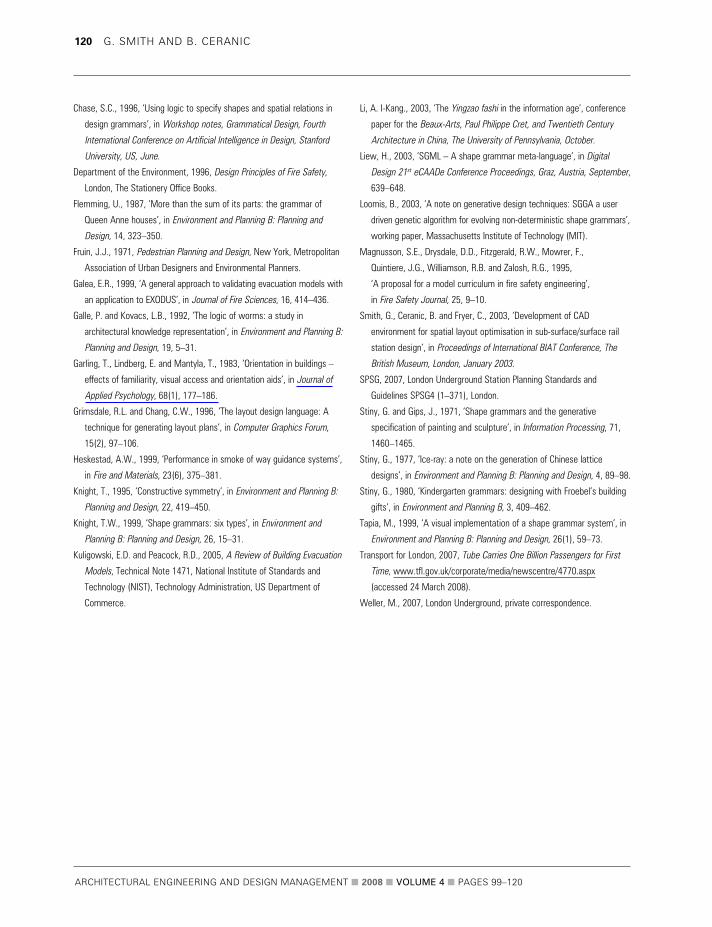