Embed Size (px)
Citation preview

Document Number: SMACRMRev. 1.5 03/2008
Simple Media Access Controller (SMAC)
User’s Guide
How to Reach Us:
Home Page:www.freescale.com
E-mail:[email protected]
USA/Europe or Locations Not Listed:Freescale SemiconductorTechnical Information Center, CH3701300 N. Alma School RoadChandler, Arizona 85224+1-800-521-6274 or [email protected]
Europe, Middle East, and Africa:Freescale Halbleiter Deutschland GmbHTechnical Information CenterSchatzbogen 781829 Muenchen, Germany+44 1296 380 456 (English)+46 8 52200080 (English)+49 89 92103 559 (German)+33 1 69 35 48 48 (French)[email protected]
Japan:Freescale Semiconductor Japan Ltd.HeadquartersARCO Tower 15F1-8-1, Shimo-Meguro, Meguro-ku,Tokyo 153-0064, Japan0120 191014 or +81 3 5437 [email protected]
Asia/Pacific:Freescale Semiconductor Hong Kong Ltd.Technical Information Center2 Dai King StreetTai Po Industrial EstateTai Po, N.T., Hong Kong+800 2666 [email protected]
For Literature Requests Only:Freescale Semiconductor Literature Distribution CenterP.O. Box 5405Denver, Colorado 802171-800-521-6274 or 303-675-2140Fax: [email protected]
Information in this document is provided solely to enable system and software implementers to use Freescale Semiconductor products. There are no express or implied copyright licenses granted hereunder to design or fabricate any integrated circuits or integrated circuits based on the information in this document.Freescale Semiconductor reserves the right to make changes without further notice to any products herein. Freescale Semiconductor makes no warranty, representation or guarantee regarding the suitability of its products for any particular purpose, nor does Freescale Semiconductor assume any liability arising out of the application or use of any product or circuit, and specifically disclaims any and all liability, including without limitation consequential or incidental damages. “Typical” parameters that may be provided in Freescale Semiconductor data sheets and/or specifications can and do vary in different applications and actual performance may vary over time. All operating parameters, including “Typicals”, must be validated for each customer application by customer’s technical experts. Freescale Semiconductor does not convey any license under its patent rights nor the rights of others. Freescale Semiconductor products are not designed, intended, or authorized for use as components in systems intended for surgical implant into the body, or other applications intended to support or sustain life, or for any other application in which the failure of the Freescale Semiconductor product could create a situation where personal injury or death may occur. Should Buyer purchase or use Freescale Semiconductor products for any such unintended or unauthorized application, Buyer shall indemnify and hold Freescale Semiconductor and its officers, employees, subsidiaries, affiliates, and distributors harmless against all claims, costs, damages, and expenses, and reasonable attorney fees arising out of, directly or indirectly, any claim of personal injury or death associated with such unintended or unauthorized use, even if such claim alleges that Freescale Semiconductor was negligent regarding the design or manufacture of the part.
Freescale™ and the Freescale logo are trademarks of Freescale Semiconductor, Inc. All other product or service names are the property of their respective owners.
© Freescale Semiconductor, Inc. 2005, 2006, 2007, 2008. All rights reserved.
SMAC User’s Guide, Rev. 1.5
Freescale Semiconductor iii
ContentsAbout This Book
Audience . . . . . . . . . . . . . . . . . . . . . . . . . . . . . . . . . . . . . . . . . . . . . . . . . . . . . . . . . . . . . . . . . . . . . vOrganization . . . . . . . . . . . . . . . . . . . . . . . . . . . . . . . . . . . . . . . . . . . . . . . . . . . . . . . . . . . . . . . . . . vRevision History . . . . . . . . . . . . . . . . . . . . . . . . . . . . . . . . . . . . . . . . . . . . . . . . . . . . . . . . . . . . . . . vDefinitions, Acronyms, and Abbreviations . . . . . . . . . . . . . . . . . . . . . . . . . . . . . . . . . . . . . . . . . viReferences. . . . . . . . . . . . . . . . . . . . . . . . . . . . . . . . . . . . . . . . . . . . . . . . . . . . . . . . . . . . . . . . . . . vi
Chapter 1 SMAC Introduction
1.1 Features . . . . . . . . . . . . . . . . . . . . . . . . . . . . . . . . . . . . . . . . . . . . . . . . . . . . . . . . . . . . . . . . . . . . 1-21.2 MCU Resource Requirements . . . . . . . . . . . . . . . . . . . . . . . . . . . . . . . . . . . . . . . . . . . . . . . . . . 1-21.3 Introducing BeeKit . . . . . . . . . . . . . . . . . . . . . . . . . . . . . . . . . . . . . . . . . . . . . . . . . . . . . . . . . . . 1-21.3.1 BeeKit Concepts . . . . . . . . . . . . . . . . . . . . . . . . . . . . . . . . . . . . . . . . . . . . . . . . . . . . . . . . . . 1-2
Chapter 2 Software Architecture
2.1 Block Diagram . . . . . . . . . . . . . . . . . . . . . . . . . . . . . . . . . . . . . . . . . . . . . . . . . . . . . . . . . . . . . . 2-12.2 Hardware Support . . . . . . . . . . . . . . . . . . . . . . . . . . . . . . . . . . . . . . . . . . . . . . . . . . . . . . . . . . . . 2-22.3 Security Module . . . . . . . . . . . . . . . . . . . . . . . . . . . . . . . . . . . . . . . . . . . . . . . . . . . . . . . . . . . . . 2-32.4 OTAP Module. . . . . . . . . . . . . . . . . . . . . . . . . . . . . . . . . . . . . . . . . . . . . . . . . . . . . . . . . . . . . . . 2-42.5 SMAC Data Types . . . . . . . . . . . . . . . . . . . . . . . . . . . . . . . . . . . . . . . . . . . . . . . . . . . . . . . . . . . 2-52.5.1 tTxPacket . . . . . . . . . . . . . . . . . . . . . . . . . . . . . . . . . . . . . . . . . . . . . . . . . . . . . . . . . . . . . . . 2-52.5.2 tRxPacket . . . . . . . . . . . . . . . . . . . . . . . . . . . . . . . . . . . . . . . . . . . . . . . . . . . . . . . . . . . . . . . 2-6
Chapter 3 Primitives
3.1 Application API . . . . . . . . . . . . . . . . . . . . . . . . . . . . . . . . . . . . . . . . . . . . . . . . . . . . . . . . . . . . . 3-13.1.1 MCPSDataRequest . . . . . . . . . . . . . . . . . . . . . . . . . . . . . . . . . . . . . . . . . . . . . . . . . . . . . . . . 3-13.1.2 MCPSDataIndication . . . . . . . . . . . . . . . . . . . . . . . . . . . . . . . . . . . . . . . . . . . . . . . . . . . . . . 3-23.1.3 MLMEHibernateRequest . . . . . . . . . . . . . . . . . . . . . . . . . . . . . . . . . . . . . . . . . . . . . . . . . . . 3-33.1.4 MLMEWakeRequest . . . . . . . . . . . . . . . . . . . . . . . . . . . . . . . . . . . . . . . . . . . . . . . . . . . . . . 3-43.1.5 MLMESetChannelRequest . . . . . . . . . . . . . . . . . . . . . . . . . . . . . . . . . . . . . . . . . . . . . . . . . . 3-43.1.6 MLMERXEnableRequest . . . . . . . . . . . . . . . . . . . . . . . . . . . . . . . . . . . . . . . . . . . . . . . . . . . 3-53.1.7 MLMERXDisableRequest . . . . . . . . . . . . . . . . . . . . . . . . . . . . . . . . . . . . . . . . . . . . . . . . . . 3-63.1.8 MLMESetMC13192ClockRate . . . . . . . . . . . . . . . . . . . . . . . . . . . . . . . . . . . . . . . . . . . . . . 3-63.1.9 MLMEEnergyDetect . . . . . . . . . . . . . . . . . . . . . . . . . . . . . . . . . . . . . . . . . . . . . . . . . . . . . . 3-73.1.10 MLMEMC13192SoftReset. . . . . . . . . . . . . . . . . . . . . . . . . . . . . . . . . . . . . . . . . . . . . . . . . . 3-73.1.11 MLMEMC13192XtalAdjust. . . . . . . . . . . . . . . . . . . . . . . . . . . . . . . . . . . . . . . . . . . . . . . . . 3-83.1.12 MLMELinkQuality . . . . . . . . . . . . . . . . . . . . . . . . . . . . . . . . . . . . . . . . . . . . . . . . . . . . . . . . 3-83.1.13 MLMESetMC13192TmrPrescale . . . . . . . . . . . . . . . . . . . . . . . . . . . . . . . . . . . . . . . . . . . . . 3-93.1.14 MLMEMC13192FEGainAdjust . . . . . . . . . . . . . . . . . . . . . . . . . . . . . . . . . . . . . . . . . . . . . 3-103.1.15 MLMEDozeRequest . . . . . . . . . . . . . . . . . . . . . . . . . . . . . . . . . . . . . . . . . . . . . . . . . . . . . . 3-11
SMAC User’s Guide, Rev. 1.5
iv Freescale Semiconductor
3.1.16 MLMEMC13192PAOutputAdjust . . . . . . . . . . . . . . . . . . . . . . . . . . . . . . . . . . . . . . . . . . . 3-123.1.17 MLMEGetRficVersion . . . . . . . . . . . . . . . . . . . . . . . . . . . . . . . . . . . . . . . . . . . . . . . . . . . . 3-133.1.18 MLMETestMode . . . . . . . . . . . . . . . . . . . . . . . . . . . . . . . . . . . . . . . . . . . . . . . . . . . . . . . . 3-133.1.19 MLMEMC13192ResetIndication . . . . . . . . . . . . . . . . . . . . . . . . . . . . . . . . . . . . . . . . . . . . 3-143.1.20 MCUInit . . . . . . . . . . . . . . . . . . . . . . . . . . . . . . . . . . . . . . . . . . . . . . . . . . . . . . . . . . . . . . . 3-143.1.21 UseExternalClock . . . . . . . . . . . . . . . . . . . . . . . . . . . . . . . . . . . . . . . . . . . . . . . . . . . . . . . . 3-153.1.22 UseMCUClock . . . . . . . . . . . . . . . . . . . . . . . . . . . . . . . . . . . . . . . . . . . . . . . . . . . . . . . . . . 3-153.1.23 MLMEScanRequest . . . . . . . . . . . . . . . . . . . . . . . . . . . . . . . . . . . . . . . . . . . . . . . . . . . . . . 3-163.1.24 MC13192DisableInterrupts . . . . . . . . . . . . . . . . . . . . . . . . . . . . . . . . . . . . . . . . . . . . . . . . 3-163.1.25 MC13192EnableInterrupts . . . . . . . . . . . . . . . . . . . . . . . . . . . . . . . . . . . . . . . . . . . . . . . . . 3-173.1.26 MC13192ContReset . . . . . . . . . . . . . . . . . . . . . . . . . . . . . . . . . . . . . . . . . . . . . . . . . . . . . . 3-173.1.27 MC13192Restart . . . . . . . . . . . . . . . . . . . . . . . . . . . . . . . . . . . . . . . . . . . . . . . . . . . . . . . . . 3-173.2 Security - Application API . . . . . . . . . . . . . . . . . . . . . . . . . . . . . . . . . . . . . . . . . . . . . . . . . . . . 3-183.2.1 SECSetKey . . . . . . . . . . . . . . . . . . . . . . . . . . . . . . . . . . . . . . . . . . . . . . . . . . . . . . . . . . . . . 3-183.2.2 SECSecure . . . . . . . . . . . . . . . . . . . . . . . . . . . . . . . . . . . . . . . . . . . . . . . . . . . . . . . . . . . . . 3-183.3 OTAP - Application API . . . . . . . . . . . . . . . . . . . . . . . . . . . . . . . . . . . . . . . . . . . . . . . . . . . . . 3-193.3.1 OTAPActivate . . . . . . . . . . . . . . . . . . . . . . . . . . . . . . . . . . . . . . . . . . . . . . . . . . . . . . . . . . 3-19
Appendix A SMAC Transceiver and Hardware SupportA.1 MC1319x RF Configurations . . . . . . . . . . . . . . . . . . . . . . . . . . . . . . . . . . . . . . . . . . . . . . . . . . . A-1A.1.1 MC1319x Without External Amplifiers . . . . . . . . . . . . . . . . . . . . . . . . . . . . . . . . . . . . . . . . A-2A.1.2 MC1319x With External Amplifiers . . . . . . . . . . . . . . . . . . . . . . . . . . . . . . . . . . . . . . . . . . A-5A.2 MC1320x and MC1321x RF Configurations . . . . . . . . . . . . . . . . . . . . . . . . . . . . . . . . . . . . . . . A-7A.2.1 MC1320x or MC1321x Without External Components. . . . . . . . . . . . . . . . . . . . . . . . . . . . A-7A.2.2 MC13120x or MC1321x With External Amplifiers. . . . . . . . . . . . . . . . . . . . . . . . . . . . . . . A-9
SMAC User’s Guide, Rev. 1.5
Freescale Semiconductor v
About This BookThis guide provides a detailed description of the Freescale Simple Media Access Controller (SMAC).
AudienceThis document is intended for application developers building 802.15.4 wireless applications. The latest version of the Freescale SMAC is incorporated into the Freescale BeeKit Wireless Connectivity Toolkit. The incorporation of SMAC into BeeKit makes it easier for users to employ and customize SMAC.
OrganizationThis document is organized into four chapters and one appendix.Chapter 1 Introducing SMAC — This chapter introduces SMAC features and functionality.Chapter 2 Software Architecture — This chapter describes SMAC software architecture.Chapter 3 Primitives — This chapter provides a detailed description of SMAC primitives.Appendix A SMAC Transceiver and Hardware Support - This appendix describes SMAC
controlled transceiver and hardware configuration.
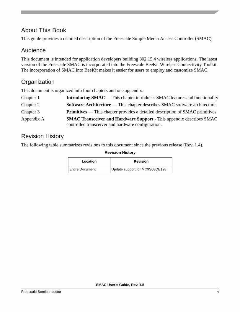
Revision HistoryThe following table summarizes revisions to this document since the previous release (Rev. 1.4).
Revision History
Location Revision
Entire Document Update support for MC9S08QE128
SMAC User’s Guide, Rev. 1.5
vi Freescale Semiconductor
Definitions, Acronyms, and AbbreviationsThe following list defines the acronyms and abbreviations used in this document.BDM debugger A debugger using the BDM interface for communication with the MCU. An
example is the P&E BDM Multilink debugger for HCS08.BDM Background Debug ModuleEVB Evaluation Boards - this term covers the 13192-EVB, 13192-SARD and
1320X-QE128-EVB boards.EVK Evaluation KitGUI Graphical User InterfaceMAC Medium Access ControlMCU MicroController UnitNVM None-Volatile MemoryPC Personal ComputerPCB Printed Circuit BoardS19 'S19' is the file extension used for the Freescale binary image format. The S19 file
encapsulates the binary image as a list of ASCII records. Each record contains a length -, address -, data - and checksum field. The 16 bit address field allows a memory space for up to 64 KB. The S19 can be generated with CodeWarrior IDE and is the product from the linking process. S19 does not contain additional information to a debugger (where to look for source files).
HIWAVE P&E HCS08 debugger GUI.CPROG P&E HCS08 flash programming tool called from HIWAVE. The tool is also
available in a command line version where scripts can be made.
ReferencesThe following sources were referenced to produce this book:
[1] Freescale 802.15.4 MAC/PHY Software Reference Manual (802154MPSRM)
[2] Zigbee.hlp (see Test Tool installation directory.\help)

SMAC User’s Guide, Rev. 1.5
Freescale Semiconductor 1-1
Chapter 1 SMAC IntroductionThe Freescale Simple Media Access Controller (SMAC) is a simple ANSI C based code stack available as sample source code. The SMAC is used for developing proprietary RF transceiver applications using a Freescale 802.15.4 transceiver. The SMAC was built to work with an HCS08 based MCU with an SPI, but it can easily be adapted to almost any processor core.
The SMAC is incorporated into the Freescale BeeKit Wireless Connectivity Toolkit. The incorporation of SMAC into BeeKit makes it easier for users to employ and customize SMAC. BeeKit generates the project files, the project folder structure has changed from previous SMAC versions, libraries are no longer used, and everything in a project is in source code. BeeKit generates a single target per project and every BeeKit generated project runs transparently with CodeWarrior Special Edition. See the SMAC release notes for version specific information.
To use any of the existing applications available in SMAC, users must first generate the applications as projects in a BeeKit solution. For more information about BeeKit, BeeKit Projects, and BeeKit Solutions, refer to the BeeKit Wireless Connectivity Toolkit User’s Guide (BKWCTKUG) and the BeeKit on-line help.
The following is a list of SMAC based demonstration applications:• Basic Packet Error Rate (PER)• Wireless UART• Accelerometer V 3.0• Range• Lighting• Test Mode• Repeater• Simple Protocol Test Client• Over the Air Programmer (OTAP)
For more details on running the Accelerometer application, refer to AN3232, Accelerometer Demonstration With the 13213-SRB (Sensor Reference Board). For more details in running the SMAC applications refer to AN3231.
For more details about the MC1319x, MC1320x and MC1321x devices, refer to the appropriate Reference Manuals and/or Data Sheets.

SMAC Introduction
SMAC User’s Guide, Rev. 1.5
1-2 Freescale Semiconductor
1.1 Features• Compact footprint:
— 2K FLASH— 10 bytes (+ maximum packet length) RAM
• MC1319x, MC1320x, and MC1321x compatible• Very-low power, proprietary, bi-directional RF communication link• ANSI C source code targeted for the HCS08 core• Low priority IRQ• Easy-to-use sample applications included• Configurable protocol differentiator to allow automatic ignore of 802.15.4 MAC packets
1.2 MCU Resource RequirementsThis section highlights MCU resource requirements.
• Internal MCU clock (optional)• Hardware SPI module or software SPI driven by four GPIOs (CLK, MISO, MOSI, and CE)• The SMAC hardware interface normally uses four GPIOs (Reset, RTXEN, ATTN and CE) but can
be configured to use as few as three, or as many as seven GPIOs.• One external IRQ from a dedicated interrupt controller, a keyboard interrupt, or another external
interrupt source
1.3 Introducing BeeKitThe current version of SMAC is released in an independent Codebase that is part of the Freescale BeeKit Wireless Connectivity Tool. To create a project for SMAC, users must employ the BeeKit Codebase that contains the SMAC code. For more information on BeeKit, refer to the BeeKit Wireless Connectivity Toolkit User’s Guide (BKWCTKUG).
For more information on the Codebase as it applies to SMAC, refer to the MC1319x, MC1320x, and MC1321x Demonstration Operation, Running SMAC Based Demonstration Operations application note (AN3231).
1.3.1 BeeKit ConceptsThis section highlights some basic BeeKit terms and concepts. Again, for a more detailed description of BeeKit, refer to the BeeKit Wireless Connectivity Toolkit User’s Guide (BKWCTKUG).Codebase A group of source files, configuration files, and generation rules that serve as a
repository from which all BeeKit demos, templates, and other applications are generated.
Solution A group of projects which are linked to a specific folder within the file structure of the computer and in this file structure, all other projects will generate their own folders.
SMAC Introduction
SMAC User’s Guide, Rev. 1.5
Freescale Semiconductor 1-3
BeeKit Project A specific group of files that are exported from BeeKit to create a CodeWarrior project in the form of an XML file.
XML Project File A BeeKit generated XML file ready for import into CodeWarrior. A CodeWarrior MCP file is generated from the BeeKit generated XML project file.
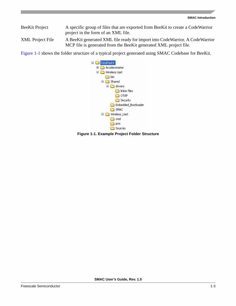
Figure 1-1 shows the folder structure of a typical project generated using SMAC Codebase for BeeKit.
Figure 1-1. Example Project Folder Structure

SMAC Introduction
SMAC User’s Guide, Rev. 1.5
1-4 Freescale Semiconductor
SMAC User’s Guide, Rev. 1.5
Freescale Semiconductor 2-1
Chapter 2 Software ArchitectureThis chapter describes the SMAC software architecture. The SMAC integration into BeeKit changed the software organization from previous versions of SMAC (SMAC 4.2 and previous). In this version of the SMAC, all of the SMAC source code is included in the application so sub projects or libraries are no longer required. This represents a far less complex project that can be compiled using CodeWarrior Special Edition.
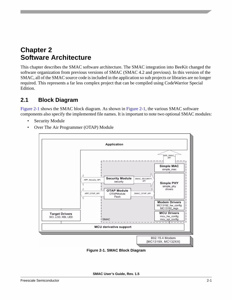
2.1 Block DiagramFigure 2-1 shows the SMAC block diagram. As shown in Figure 2-1, the various SMAC software components also specify the implemented file names. It is important to note two optional SMAC modules:
• Security Module• Over The Air Programmer (OTAP) Module
Figure 2-1. SMAC Block Diagram
Software Architecture
SMAC User’s Guide, Rev. 1.5
2-2 Freescale Semiconductor
The Security and OTAP modules and their APIs are included in the BeeKit project when the following SMAC BeeKit properties are set to “True”:
• Security Enabled• OTAP Enabled
An API is implemented in the SMAC as a C header file (.h) that allows access to the code. The code includes the API to specific functions. So, the application interface with the SMAC is accomplished by including the APP_SMAC_API.h file, which makes references to the required functions within the SMAC and provides the application with SMAC functionality.
2.2 Hardware SupportThis section describes the SMAC hardware support for the MCU, transceiver, antenna switch, and LNA. The SMAC can be easily ported to any MCU, as long as the system requirements are met. To port to another MCU, perform the following tasks:
1. Remove the mc9s08gb60.c/mc9sqe128.c file from the BeeKit project.2. Add the specific c support file for the required MCU3. Update the linker file (.prm file)4. Update the derivative.h file to include the specific header file5. Update the SMAC lower layers (MCU and SPI configuration files)6. Update the application drivers (such as SCI, LED, KBI, etc.)
The SMAC supports the following Freescale transceiver families:• MC1319x• MC1320x• MC1321x
The changes required in the software to support any of the Freescale transceivers are generated automatically by BeeKit after exporting a solution with the projects correctly configured. For more information on exporting projects, see the BeeKit Wireless Connectivity Toolkit User’s Guide (BKWCTKUG), and the BeeKit on-line help.
SMAC projects support different target boards (those available in Freescale ZigBee kits) in the files. But it is easy to port an SMAC application from a standard target to a custom target by modifying the target board files included in the generated project. For example, see the MC1319XSARD.c and MC1319XSARD.h files to see a project generated by BeeKit that uses the Freescale Sensor Applications Reference Design (SARD) board as a target.
The SMAC contains support for hardware that is controlled by GPIOs configured at the target board header file: These hardware options are as follows:
• External Antenna Switch• LNA• PA
For the External Antenna Switch, SMAC supports the following configurations:
Software Architecture
SMAC User’s Guide, Rev. 1.5
Freescale Semiconductor 2-3
• For the MC1319x transceivers, a dual antenna (no external antenna switch)• For the MC1319x, MC1320x, and MC1321x transceivers, a single antenna using an external
antenna switch controlled by an MCU GPIO pin.• For MC1320x and MC1321x transceivers, a single antenna using an external antenna switch
controlled by the BT_Bias pin of the transceiver.• For MC1320x and MC1321x transceivers, a single antenna using the internal antenna switch.
For more information on the internal antenna switch of the MC1321X and how it applies to SMAC, refer to Appendix A, ”SMAC Transceiver and Hardware Support”.
2.3 Security ModuleThe security module is a simple software component that allows the encryption and decryption of messages through its API. This section describes the procedure for implementing security in an SMAC application. The module can be configured to work with different encryption algorithms, but currently, only the simple XOR security algorithm (SEC_MODE_SIMPLEXOR) is implemented.
If security is enabled, more RAM is required for the buffer key.
The Security Module’s API is as follows:
extern void SECSecure(UINT8 *pBuffer, UINT8 u8Length);extern void SECSetKey(UINT8 *pBuffer, UINT8 u8Length);
The SECSetKey function is usually called at application start-up in order to configure the Key and its length. If SECSetKey is not called at when the application starts and the security module is enabled, this module uses a default key configured from BeeKit.
The SECSecure function encrypts/decrypts a buffer using the configured key. It is automatically called from the SMAC for the TX and RX operations. It is also available to the user so other buffers can be encrypted/decrypted.
To double buffer, this implementation of the security module replaces the original data buffer with the encrypted data.
Software Architecture
SMAC User’s Guide, Rev. 1.5
2-4 Freescale Semiconductor
2.4 OTAP ModuleThe OTAP module allows users to update device firmware without wires. The OTAP system consists of the following:
• A standard messaging interface• An embedded OTAP module that tracks the progress of the transfer and handles switching the
context or aborts the reprogramming in the destination device• A programmer device that transmits the new image to the destination
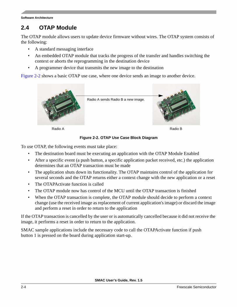
Figure 2-2 shows a basic OTAP use case, where one device sends an image to another device.
Figure 2-2. OTAP Use Case Block Diagram
To use OTAP, the following events must take place:• The destination board must be executing an application with the OTAP Module Enabled• After a specific event (a push button, a specific application packet received, etc.) the application
determines that an OTAP transaction must be made• The application shuts down its functionality. The OTAP maintains control of the application for
several seconds and the OTAP returns either a context change with the new application or a reset• The OTAPActivate function is called• The OTAP module now has control of the MCU until the OTAP transaction is finished• When the OTAP transaction is complete, the OTAP module should decide to perform a context
change (use the received image as replacement of current application's image) or discard the image and perform a reset in order to return to the application
If the OTAP transaction is cancelled by the user or is automatically cancelled because it did not receive the image, it performs a reset in order to return to the application.
SMAC sample applications include the necessary code to call the OTAPActivate function if push button 1 is pressed on the board during application start-up.
Radio A sends Radio B a new image.
Radio A Radio B
Software Architecture
SMAC User’s Guide, Rev. 1.5
Freescale Semiconductor 2-5
2.5 SMAC Data TypesThe following list shows the fundamental data types and the naming convention used in SMAC:UINT8 Unsigned 8 bit definitionUINT16 Unsigned 16 bit definitionUINT32 Unsigned 32 bit definitionINT8 Signed 8 bit definitionINT16 Signed 16 bit definitionINT32 Signed 32 bit definition
Usage
These data types are used in the SMAC project as well as in the Applications projects and they are defined in the pub_def.h file.
2.5.1 tTxPacketThis structure defines the variable to be transmitted by SMAC. It is located in the pub_def.h file and is defined as follows:
typedef struct {UINT8 u8DataLength;UINT8 *pu8Data;} tTxPacket;
Membersu8DataLength The number of bytes to transmit.* pu8Data A pointer to the data buffer to transmit.
Usage
This data type is used by an application in the following manner:1. The application declares the tTxPacket gsTxPacket variable.2. The application creates a data buffer of data to send: UINT8 gau8TxDataBuffer[20];3. The application loads the number of bytes to send into u8DataLength in the tTxPacket structure:
gsTxPacket.u8DataLength = 0;
4. The application loads the address of the data buffer to send into data field of the gsTxPacketstructure: gsTxPacket.pu8Data = &gau8TxDataBuffer[0];

Software Architecture
SMAC User’s Guide, Rev. 1.5
2-6 Freescale Semiconductor
2.5.2 tRxPacketThis structure defines the variable to be received by the SMAC and is located in the pub_def.h file. It is defined as follows:
typedef struct {UINT8 u8MaxDataLength;UINT8 u8DataLength;UINT8 *pu8Data;UINT8 u8Status;} tRxPacket;
Membersu8MaxDataLength This field specifies the maximum packet size to accept. If the packet received is
greater than u8MaxDataLength then the packet is dropped and the application is not notified.
u8DataLength This field contains the length in bytes of the received packet.*pu8Data This pointer specifies to the SMAC where the application would like to have the
received data copied into.u8Status This field has two possibilities: (SUCCESS, TIMEOUT). This field allows the
application to determine if the data indication is due to a received packet or a timeout. In the MCPSDataIndication function, the application must check this field to determine if the indication is due for a timeout or good data.
SMAC User’s Guide, Rev. 1.5
Freescale Semiconductor 3-1
Chapter 3 PrimitivesThe following sections provide a detailed description of SMAC primitives associated with the three SMAC APIs.
3.1 Application APIThis section highlights MCU resource requirements and details the Application API primitives.
3.1.1 MCPSDataRequestThis data primitive is used to send a packet. It is used in the following manner:
PrototypeUINT8 MCPSDataRequest(tTxPacket *psTxPacket);
ArgumentstTxPacket *: Packet to transmit
Returns{SUCCESS}
Usage• Load the packet into a tTxPacket variable. In the examples called “gsTxPacket”• Application calls MCPSDataRequest(&gsTxPacket)• Data is transmitted by radio• MCPSDataRequest() returns {SUCCESS}
This command places the MCU into WAIT until the radio is finished transmitting the packet. As a result, the MCU is blocked and the user application halts until the packet is transmitted.
NOTEThe only possible return value of this function is SUCCESS.

Primitives
SMAC User’s Guide, Rev. 1.5
3-2 Freescale Semiconductor
3.1.2 MCPSDataIndicationThis callback function (a function that is located within the user’s application code and is needed by the SMAC) needs to be placed in the application. This allows the SMAC to call this function when data is received by the radio to be processed by the application. It is used as follows:
Prototypevoid MCPSDataIndication(tRxPacket *gsRxPacket);
ArgumentstRxPacket *:A pointer to a variable where the received packet will be placed
Returnsvoid
Usage
This function turns on the radio receiver by using the MLMERXEnableRequest call. When the radio receives data, the lower levels will call MCPSDataIndication. The data, status, and the number of bytes received will be contained in the tRxPacket structure. In the sample applications, the variable is gsRxPacket.
The application will then check the status field of gsRxPacket to determine if the packet received is:• SUCCESS — A good packet
— Application reads the number of bytes received via the gsRxPacket.u8DataLength field— Application will then parse the data in the gsRxPacket.pu8Data field
• TIMEOUT — A timeout occurred. It is used when the receiver is turned on for a specific amount of time. See MLMERXEnableRequest
• OVERFLOW — A packet greater than the requested number of bytes has been received
Notes
The following code is an example that uses this function. It is called once a packet is received, then it verifies whether it is a successful reception or a timeout. If it was a successful reception, it shows the data payload through the SCI. If it was a TIMEOUT, it leads the application to the TIMEOUT_STATE.
void MCPSDataIndication(tRxPacket *gsRxPacket) { if (gsRxPacket->u8Status == SUCCESS) { /* Packet received */ SCITransmitStr(&gsRxPacket->pu8Data[0]); gi8AppStatus = TRANSMIT_ACK; } if (gsRxPacket->u8Status == TIMEOUT) { /* Received TIMEOUT */ gi8AppStatus = TIMEOUT_STATE;
Primitives
SMAC User’s Guide, Rev. 1.5
Freescale Semiconductor 3-3
} }
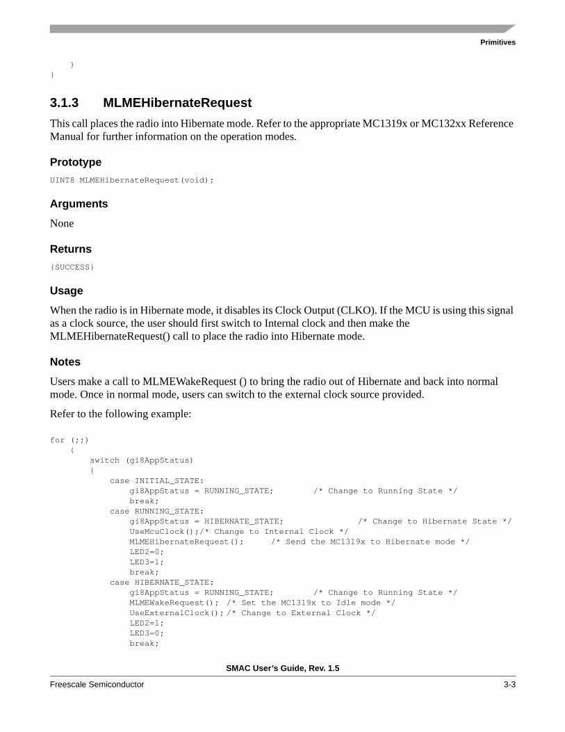
3.1.3 MLMEHibernateRequestThis call places the radio into Hibernate mode. Refer to the appropriate MC1319x or MC132xx Reference Manual for further information on the operation modes.
PrototypeUINT8 MLMEHibernateRequest(void);
Arguments
None
Returns{SUCCESS}
Usage
When the radio is in Hibernate mode, it disables its Clock Output (CLKO). If the MCU is using this signal as a clock source, the user should first switch to Internal clock and then make the MLMEHibernateRequest() call to place the radio into Hibernate mode.
Notes
Users make a call to MLMEWakeRequest () to bring the radio out of Hibernate and back into normal mode. Once in normal mode, users can switch to the external clock source provided.
Refer to the following example:
for (;;) { switch (gi8AppStatus) { case INITIAL_STATE: gi8AppStatus = RUNNING_STATE; /* Change to Running State */ break; case RUNNING_STATE: gi8AppStatus = HIBERNATE_STATE; /* Change to Hibernate State */ UseMcuClock();/* Change to Internal Clock */ MLMEHibernateRequest(); /* Send the MC1319x to Hibernate mode */ LED2=0; LED3=1; break; case HIBERNATE_STATE: gi8AppStatus = RUNNING_STATE; /* Change to Running State */ MLMEWakeRequest(); /* Set the MC1319x to Idle mode */ UseExternalClock(); /* Change to External Clock */ LED2=1; LED3=0; break;
Primitives
SMAC User’s Guide, Rev. 1.5
3-4 Freescale Semiconductor
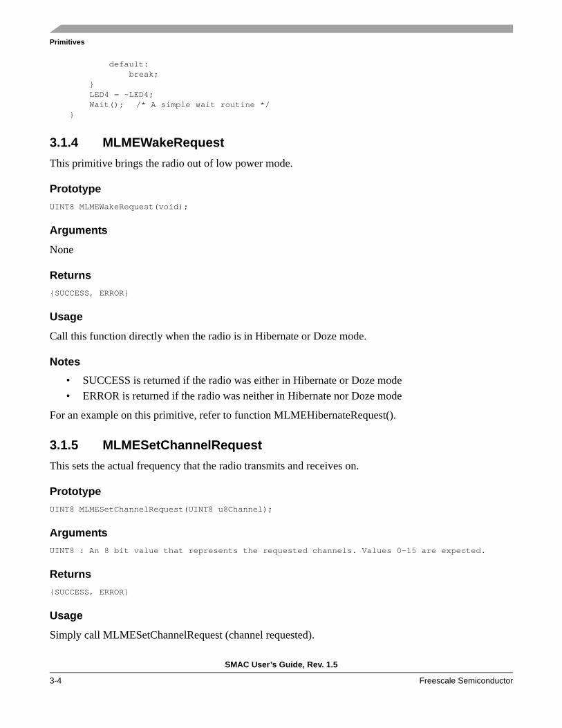
default: break; } LED4 = ~LED4; Wait(); /* A simple wait routine */ }
3.1.4 MLMEWakeRequestThis primitive brings the radio out of low power mode.
PrototypeUINT8 MLMEWakeRequest(void);
Arguments
None
Returns{SUCCESS, ERROR}
Usage
Call this function directly when the radio is in Hibernate or Doze mode.
Notes• SUCCESS is returned if the radio was either in Hibernate or Doze mode• ERROR is returned if the radio was neither in Hibernate nor Doze mode
For an example on this primitive, refer to function MLMEHibernateRequest().
3.1.5 MLMESetChannelRequestThis sets the actual frequency that the radio transmits and receives on.
PrototypeUINT8 MLMESetChannelRequest(UINT8 u8Channel);
ArgumentsUINT8 : An 8 bit value that represents the requested channels. Values 0-15 are expected.
Returns{SUCCESS, ERROR}
Usage
Simply call MLMESetChannelRequest (channel requested).

Primitives
SMAC User’s Guide, Rev. 1.5
Freescale Semiconductor 3-5
Notes
Channels 0-15 are expected.• SUCCESS is returned if a correct channel is requested (0-15)• ERROR is returned if the value passed is not between 0-15. Channel 8 is selected by default
3.1.6 MLMERXEnableRequestPlaces the radio into receive mode on the channel selected by MLMESetChannelRequest ().
PrototypeUINT8 MLMERXEnableRequest(tRxPacket *psRxPacket, UINT32 u32Timeout);
ArgumentstRxPacket *:Location of the buffer to store the incoming data.
UINT32:32-bit timeout value.
Returns{SUCCESS, ERROR}
Usage• Application creates a buffer to store incoming data. In the sample code, it is named
gau8RxDataBuffer
• Application declares a variable of type tRxPacket. In the sample code it is defined as gsRxPacket• Load the address of the receive buffer into the * pu8Data field in the gsRxPacket variable• Load the maximum packet length to receive into u8MaxDataLength field• Call MLMERXEnableRequest with the tRxPacket variable and a 32-bit timeout value• The SMAC will let the application know that data is received via the MCPSDataIndication
callback function
Notes
ERROR return implies that the receiver did not go into receive mode.
u32Timeout value of zero causes the receiver to never timeout and stay in receive mode until a valid data packet is received or the MLMERXDisableRequest function is called. At those points the radio will return to idle mode.
To turn off the receiver before a valid packet is received, the MLMERXDisableRequest call can be used.
Primitives
SMAC User’s Guide, Rev. 1.5
3-6 Freescale Semiconductor
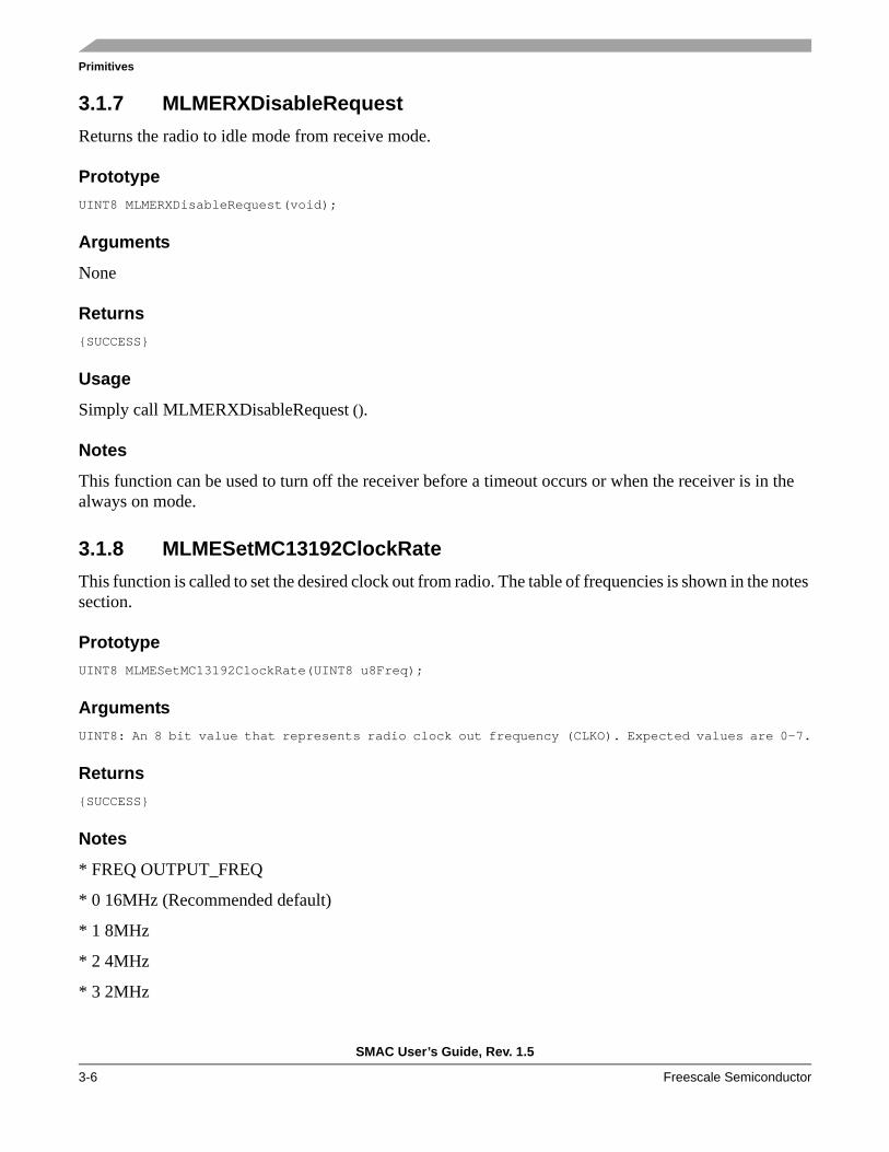
3.1.7 MLMERXDisableRequestReturns the radio to idle mode from receive mode.
PrototypeUINT8 MLMERXDisableRequest(void);
Arguments
None
Returns{SUCCESS}
Usage
Simply call MLMERXDisableRequest ().
Notes
This function can be used to turn off the receiver before a timeout occurs or when the receiver is in the always on mode.
3.1.8 MLMESetMC13192ClockRateThis function is called to set the desired clock out from radio. The table of frequencies is shown in the notes section.
PrototypeUINT8 MLMESetMC13192ClockRate(UINT8 u8Freq);
ArgumentsUINT8: An 8 bit value that represents radio clock out frequency (CLKO). Expected values are 0-7.
Returns{SUCCESS}
Notes
* FREQ OUTPUT_FREQ
* 0 16MHz (Recommended default)
* 1 8MHz
* 2 4MHz
* 3 2MHz

Primitives
SMAC User’s Guide, Rev. 1.5
Freescale Semiconductor 3-7
* 4 1MHz
* 5 62.5kHz
* 6 32.786kHz
* 7 16.393kHz
3.1.9 MLMEEnergyDetectThis call starts an energy detect (ED)/ Clear Channel Assessment (CCA) cycle and returns the energy value (-power/2) via the returned argument. For example, if the Energy Detect returns 80 then the interpreted value is -80/2 or -40 dBm.
PrototypeUINT8 MLMEEnergyDetect(void);
Arguments
None
ReturnsUINT8: An unsigned 8-bit value representing the energy on the current channel.
3.1.10 MLMEMC13192SoftResetThe MLMEMC13192SoftReset function is called to perform a soft reset to the radio.
PrototypeUINT8 MLMEMC13192SoftReset(void);
Arguments
None
Returns{SUCCESS}
Usage
Simply call the MLMEMC13192SoftReset () function directly.
Notes
When this function is called, a reset indication should be sent back to the application through the MLMEMC13192ResetIndication callback function. It is up to the application to handle this event.

Primitives
SMAC User’s Guide, Rev. 1.5
3-8 Freescale Semiconductor
3.1.11 MLMEMC13192XtalAdjustThis function is used to adjust the radio reference clock by a trim value. For more information of
PrototypeUINT8 MLMEMC13192XtalAdjust(UINT8 u8ReqValue);
ArgumentsUINT8: 8 bit value representing the trim value to the oscillator.
Returns{SUCCESS}
Usage
Simply call the MLMEMC13192XtalAdjust () function directly.
3.1.12 MLMELinkQualityThis function returns an integer value that is the link quality from the last received packet of the form: dBm = (-Link Quality/2).
PrototypeUINT8 MLMELinkQuality (void);
Arguments
None
ReturnsUINT8: 8 bit value representing the link quality value
Usage
Call MLMERXEnableRequest.
Wait for a MCPSDataIndication.
Call MLMELinkQuality.
Notes
The value of the link quality is valid and preserved until the next received packet.
Primitives
SMAC User’s Guide, Rev. 1.5
Freescale Semiconductor 3-9
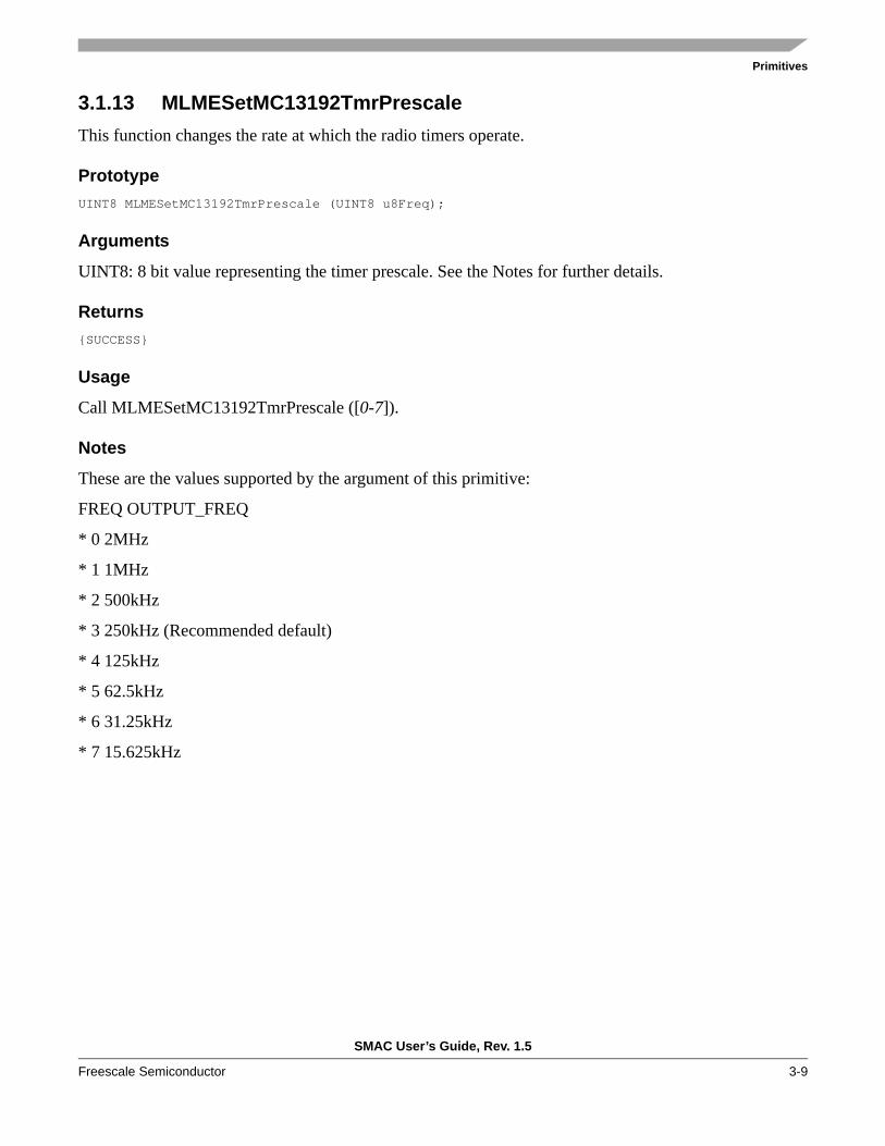
3.1.13 MLMESetMC13192TmrPrescaleThis function changes the rate at which the radio timers operate.
PrototypeUINT8 MLMESetMC13192TmrPrescale (UINT8 u8Freq);
Arguments
UINT8: 8 bit value representing the timer prescale. See the Notes for further details.
Returns{SUCCESS}
Usage
Call MLMESetMC13192TmrPrescale ([0-7]).
Notes
These are the values supported by the argument of this primitive:
FREQ OUTPUT_FREQ
* 0 2MHz
* 1 1MHz
* 2 500kHz
* 3 250kHz (Recommended default)
* 4 125kHz
* 5 62.5kHz
* 6 31.25kHz
* 7 15.625kHz
Primitives
SMAC User’s Guide, Rev. 1.5
3-10 Freescale Semiconductor
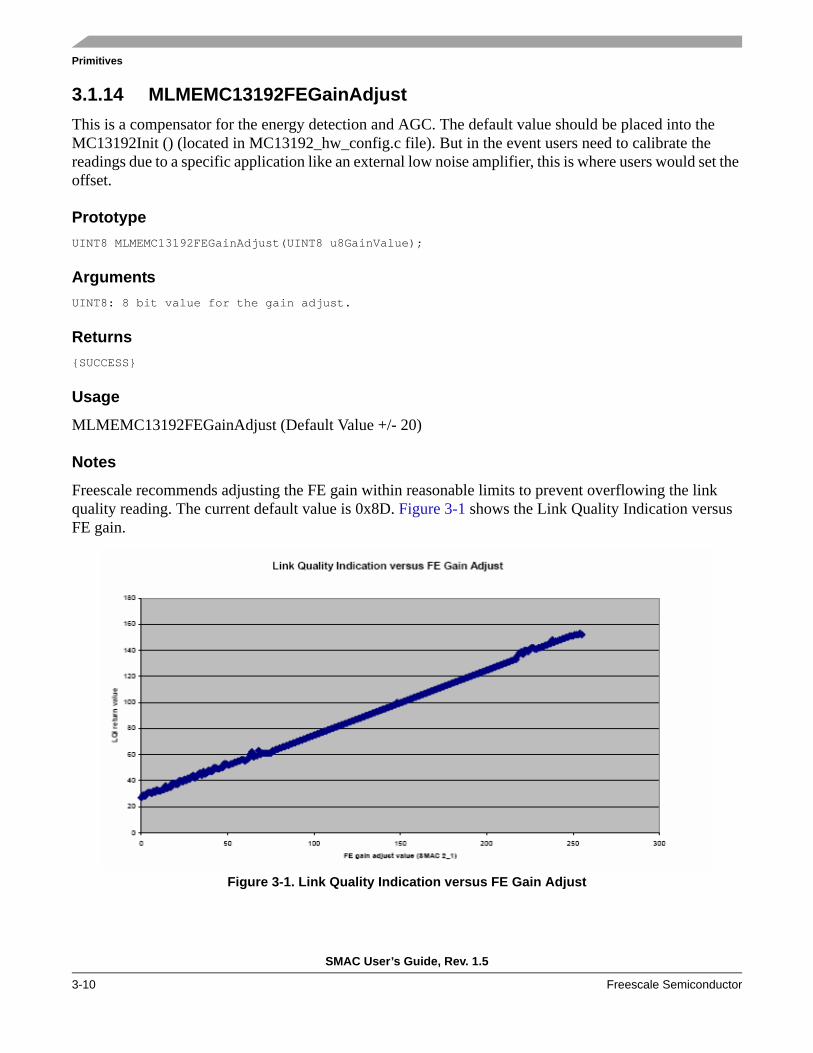
3.1.14 MLMEMC13192FEGainAdjustThis is a compensator for the energy detection and AGC. The default value should be placed into the MC13192Init () (located in MC13192_hw_config.c file). But in the event users need to calibrate the readings due to a specific application like an external low noise amplifier, this is where users would set the offset.
PrototypeUINT8 MLMEMC13192FEGainAdjust(UINT8 u8GainValue);
ArgumentsUINT8: 8 bit value for the gain adjust.
Returns{SUCCESS}
Usage
MLMEMC13192FEGainAdjust (Default Value +/- 20)
Notes
Freescale recommends adjusting the FE gain within reasonable limits to prevent overflowing the link quality reading. The current default value is 0x8D. Figure 3-1 shows the Link Quality Indication versus FE gain.
Figure 3-1. Link Quality Indication versus FE Gain Adjust

Primitives
SMAC User’s Guide, Rev. 1.5
Freescale Semiconductor 3-11
3.1.15 MLMEDozeRequestDoze request allow the user to put the radio either in Normal Doze Mode (without CLKO but with automatic wake up) or Acoma Mode (with CLKout, but without timeout). Review the appropriate MC1319x or MC132xx Reference Manual for details regarding Acoma Doze and Normal Doze Modes.
PrototypeUINT8 MLMEDozeRequest(UINT32 u32Timeout);
Arguments
UINT32 Is the automatic wake up time for this mode.
Returns{SUCCESS}
Usage
To use Acoma Mode, users should call this function with “0” as parameter. Then, the SMAC sets the radio in Acoma Mode with enabled CLKO Output. To exit from this state, users should call the MLMEWakeRequest function.
To use Normal Doze Mode, users should call this function with the desired timeout. Then the SMAC places the radio in Doze Mode. This gives the user only 128 clock pulses more before disconnecting CLKO, so users might execute a low power instruction (such as Wait). Once the timeout is reached, the radio wakes up and performs an IRQ Interrupt (attended by the SMAC).
Notes
The maximum clock out frequency during Doze Mode or Acoma Mode is equal to or less than 1MHz. The SMAC does no error checking for this when entering Doze Mode. The application needs to handle this requirement.
The CLKO resumes after the radio exits Doze Mode. This CLKO feature is optional and is controlled by setting register 0x7 bit 9. The reset value for the CLKO pin does not provide a CLKO in Doze Mode. If the radio is reset, this bit needs to be set in order to provide the CLKO.

Primitives
SMAC User’s Guide, Rev. 1.5
3-12 Freescale Semiconductor
3.1.16 MLMEMC13192PAOutputAdjustThis function adjusts the output power of the transmitter. Table 3-1 shows the output power at the antenna versus 0-15, maximum, and minimum power settings.
PrototypeUINT8 MLMEMC13192PAOutputAdjust(UINT8 u8PaValue);
ArgumentsUINT8: 8 bit value for the output power desired. Values 0-15 are required.
Returns{SUCCESS, OVERFLOW}
Usage
This function can be called with an argument between 0 and 15 or using the MIN_POWER, MAX_POWER and NOMINAL_POWER macros. Table 3-1 shows these values.
Notes
OVERFLOW is returned when this function is called with a value >15.
Table 3-1. U8PaValue
U8PaValue value
Typical Differential Power at Output Contact (dBm)
U8PaValue value
Typical Differential Power at Output Contact (dBm)
0b0000 -16.6 0b1000 -1.0
0b0001 -16.0 0b1001 -0.5
0b0010 -15.3 0b1010 0.0
0b0011 -14.8 0b1011 0.4
0b0100 -8.8 0b1100 2.1
0b0101 -8.1 0b1101 2.8
0b0110 -7.5 0b1110 3.5
0b0111 -6.9 0b1111 3.6
Primitives
SMAC User’s Guide, Rev. 1.5
Freescale Semiconductor 3-13
3.1.17 MLMEGetRficVersionThis function is used to read the version number of the radio.
PrototypeUINT8 MLMEGetRficVersion(void);
Arguments
None
ReturnsUINT8: 8 bit value representing the version of the radio
Usage
Simply call the MLMEGetRficVersion() function.
3.1.18 MLMETestModeBy employing this function, users can execute a test of the radio. Some basic test modes are necessary to assist SMAC users evaluate their hardware. Test mode implements the following:
• PRBS9 Mode — Repeatedly sends out a 64 byte packet from the PRBS9 algorithm. All packets that are transmitted in this mode are identical
• force_idle — Places the radio back into idle mode• Continuos RX — Places the radio into receive mode and allows developers to look for any spectral
issues related to the RX section of the radio. Also, this mode can be used to measure the static RX current for the radio
• Continuos TX without modulation — Allows an RF engineer to characterize the TX output power and look for issues related to this CW mode
• Continuos TX with modulation — Allows an RF engineer to characterize the basic EVM and capture the spectral envelope while modulating
Prototypevoid MLMETestMode (tTxPacket *psPacket, UINT8 u8mode);
ArgumentstTxPacket: A packet to transmit.UINT8: The test mode to start.
Returnsvoid
Primitives
SMAC User’s Guide, Rev. 1.5
3-14 Freescale Semiconductor
Usage
Call the MLMETestMode() function with the packet to be transmitted and the mode to be executed. See the notes for a list of modes implemented.
Notes
This following is a list of the modes implemented (defined as Macros):PULSE_TX_PRBS9 Continuously transmits a PRBS9 pattern.FORCE_IDLE Forces the radio to back to the original IDLE mode.CONTINUOUS_RX Sets the radio into continuous RX mode.CONTINUOUS_TX_MOD Sets the device to continuously transmit a 10101010 pattern.CONTINUOUS_TX_NOMOD Sets the device to continuously transmit an unmodulated CW.
3.1.19 MLMEMC13192ResetIndication This callback function (a function that is located within the user’s application code and is needed by the SMAC) needs to be placed in the application. This allows the SMAC to call this function when a SoftReset has occurred. It is used as follows:
Prototypevoid MLMEMC13192ResetIndication(void);
Arguments
(none)
Returnsvoid
Usage
This function deals with the soft reset condition on the radio triggered by the MLMEMC13192SoftReset() function. A soft reset writes to register 0x00 of the radio. A hard reset asserts the reset line on the radio. Both resets produce the same response with respect to SMAC.
3.1.20 MCUInitThis function initializes the MCU for communication with the transceiver.
Prototypevoid MCUInit(void);
Arguments
(none)
Primitives
SMAC User’s Guide, Rev. 1.5
Freescale Semiconductor 3-15
Returns
nothing
Usage
Use this function like a generic MCU initialization prior to any configuration of the transceiver.
Notes
This function writes to write-once registers. If users plan to employ any functionality configured in this type of register, refer to the code of the MCUInit in the mcu_hw_config.c file.
3.1.21 UseExternalClockThis function configures the MCU to run using the external clock. In all of the Freescale target boards, the external clock is connected to the CLKO signal from the transceiver.
Prototypevoid UseExternalClock(void);
Arguments
NoneReturns
Nothing
Usage
Configure the CLKO signal using the MLMESetMC13192ClockRate function and then switch to the external clock.
Notes
Refer to the appropriate transceiver reference manual for more information about the behavior of the CLKO signal in the various transceiver modes.
3.1.22 UseMCUClockThis function configures the MCU to run using the internal clock.
Prototypevoid UseMCUClock(void);
Arguments
None

Primitives
SMAC User’s Guide, Rev. 1.5
3-16 Freescale Semiconductor
Returns
Nothing
Usage
Call this function and the MCU starts running from the internal oscillator.
Notes
Refer to the appropriate MCU reference manual for more information about clock frequency characteristics that will be employed to run the MCU. This function is primarily used before placing the transceiver in a low power mode.
3.1.23 MLMEScanRequestThis function scans the different channels using one out of two techniques and returns the amount of energy in all of the channels.UINT8 MLMEScanRequest(UINT8 flags, UINT8 *pu8ChannelScan);
ArgumentsUINT8: Technique to be used (SCAN_MODE_CCA or SCAN_MODE_ED)UINT8 *: The buffer where the values of the scan will be returned.
ReturnsUINT8: The clearest channel.
Usage
Call this function with the selected technique and a buffer of 16 elements.
3.1.24 MC13192DisableInterruptsThis function disables the interrupts that are used by SMAC.void MC13192DisableInterrupts(void);
Arguments
None
Returns
Nothing
Usage
Call this function to prevent SMAC from generating interrupts.

Primitives
SMAC User’s Guide, Rev. 1.5
Freescale Semiconductor 3-17
Notes
If the interrupts are disabled, certain SMAC functions will hang up the system if called.
3.1.25 MC13192EnableInterruptsThis function enables the interrupts that are used by SMAC.void MC13192EnableInterrupts(void);
Arguments
None
Returns
Nothing
Usage
Call this function to allow SMAC to generate interrupts.
3.1.26 MC13192ContResetThis function asserts the reset line of the transceiver, shutting it down to its lowest power mode.void MC13192ContReset(void);
Arguments
None
Returns
Nothing
Usage
Call this function to turn the transceiver off.
3.1.27 MC13192RestartThis function deasserts the reset line, thus it power the transceiver up.void MC13192Restart(void);
Arguments
None
Returns
Nothing

Primitives
SMAC User’s Guide, Rev. 1.5
3-18 Freescale Semiconductor
Usage
Call this function to turn the transceiver on.
3.2 Security - Application APIThis section describes the functions available for the application from the security module.
3.2.1 SECSetKeyThis function sets the internal key to be used in the encryption/decryption mechanism.
Prototypevoid SECSetKey(UINT8 *pBuffer, UINT8 u8Length)
ArgumentsUINT8 *: This is the pointer to the key to be usedUINT8: This is the length of the key.
Returns
Nothing
Usage
Use this function prior to any call to SECSecure function, in order to set the key that will be used for encryption/decryption.
Notes
By default the key length is set to 0. A key length of 0 will neglect any secure request.
3.2.2 SECSecureThis function symmetrically encrypts/decrypts a buffer using the previously defined key. The encrypted data overrides the original buffer.
Prototypevoid SECSecure(UINT8 *pBuffer, UINT8 u8Length);
ArgumentsUINT8 *: This is the buffer to be encrypted/decrypted.UINT8: This is the length of the buffer.
Returns
Nothing

Primitives
SMAC User’s Guide, Rev. 1.5
Freescale Semiconductor 3-19
Usage
Call this function with a pointer to the data buffer to be encrypted and the length of the buffer. After this call, the data buffer will now contain the encrypted/decrypted data.
3.3 OTAP - Application APIThis section details the functions required to use the OTAP module from the application. Only one function is currently provided.
3.3.1 OTAPActivateThis function invokes the Over The Air Programming (OTAP) module. The OTAP module can last several seconds, thus, the application should not depend on returning from OTAP. The exit after the OTAP is a reset.
Prototypevoid OTAPActivate(void);
Arguments
None
Returns
Nothing
Usage
Call this function when the application is not performing its functionality.
Notes
It is very important that the application calls this function either prior to starting its functionality or after shutting it down. The SMAC applications enter into OTAP mode by pressing button 1 on one of the boards during a reset.

Primitives
SMAC User’s Guide, Rev. 1.5
3-20 Freescale Semiconductor

SMAC User’s Guide, Rev. 1.5
Freescale Semiconductor A-1
Appendix A SMAC Transceiver and Hardware SupportThe SMAC provides support for controlling the RF configuration of Freescale's MC1319x, and MC132xx, transceivers and for controlling the power and mode of external RF hardware modules, such as an antenna switch, receive low noise amplifier (LNA) and/or transmit power amplifier (PA). The SMAC can be enabled to:
• Provide power to an antenna switch through a transceiver GPIO• Switch the state of an antenna switch based on RX(CCA)/TX• Enable an LNA based on RX (CCA)• Enable a PA based on TX
The individual cases are covered based on the target transceiver.
NOTEIn the following discussions on programming transceiver control bits, refer to the appropriate device Reference Manual for register models and function of the appropriate control bits.
A.1 MC1319x RF ConfigurationsThe MC1319x family only supports a dual port mode of RF operation where the RIN_X input port is separate from the PAO_X output port. The RF circuit always requires an antenna switch for a single-ended antenna. An external LNA and/or PA are not required, but may be used.
SMAC Transceiver and Hardware Support
SMAC User’s Guide, Rev. 1.5
A-2 Freescale Semiconductor
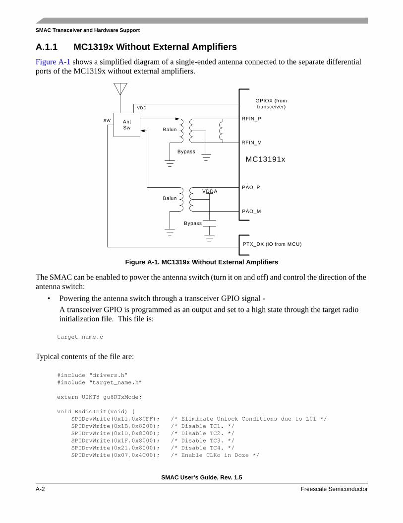
A.1.1 MC1319x Without External AmplifiersFigure A-1 shows a simplified diagram of a single-ended antenna connected to the separate differential ports of the MC1319x without external amplifiers.
Figure A-1. MC1319x Without External Amplifiers
The SMAC can be enabled to power the antenna switch (turn it on and off) and control the direction of the antenna switch:
• Powering the antenna switch through a transceiver GPIO signal -A transceiver GPIO is programmed as an output and set to a high state through the target radio initialization file. This file is:
target_name.c
Typical contents of the file are:
#include “drivers.h”#include “target_name.h”
extern UINT8 gu8RTxMode;
void RadioInit(void) { SPIDrvWrite(0x11,0x80FF); /* Eliminate Unlock Conditions due to L01 */ SPIDrvWrite(0x1B,0x8000); /* Disable TC1. */ SPIDrvWrite(0x1D,0x8000); /* Disable TC2. */ SPIDrvWrite(0x1F,0x8000); /* Disable TC3. */ SPIDrvWrite(0x21,0x8000); /* Disable TC4. */ SPIDrvWrite(0x07,0x4C00); /* Enable CLKo in Doze */
Balun
Bypass
RFIN_P
RFIN_M
PAO_P
PAO_M
MC13191x
AntSw
Balun
VDD
VDDA
Bypass
SW
GPIOX (fromtransceiver)
PTX_DX (IO from MCU)
SMAC Transceiver and Hardware Support
SMAC User’s Guide, Rev. 1.5
Freescale Semiconductor A-3
SPIDrvWrite(0x0C,0x0381); /* IRQ pull-up disable. Vdd for RF switch is set*/ SPIDrvWrite(0x04,0xA08D); /* New cal value */ SPIDrvWrite(0x05,0x8351); /* Acoma, TC1, Doze, ATTN masks, LO1, CRC */ SPIDrvWrite(0x06,0x4720); /* CCA, TX, RX, energy detect */ SPIDrvWrite(0x0B,0xC0FE); /* IRQ pull-up disable. Vdd for RF switch is set*/
/* Advance the state variable to Idle */ gu8RTxMode = IDLE_MODE;}
In this code, writing Register (0x0C, 0x0381) sets the output state of transceiver pin GPIO1 to a high, and then writing Register (0x0B, 0xC0FE) enables GPIO1 as an output. For this example, GPIO1 supplies VDD to the antenna switch.
NOTEIn the SMAC code, the antenna switch is powered at initialization, but it is up to the programmer to power off the antenna switch when and if desired.
• Controlling direction of antenna switch -An MCU I/O is programmed as an output and is used to change the antenna switch between transmit and receive modes. The antenna switch mode timing is controlled appropriately based on the state of the SMAC. To enable the antenna switch option:
1. “ANTENNA_SWITCH” must be defined in the compile switch options for the target in the Codewarrior IDE.
2. The antenna switch control signal must be mapped to the desired MCU I/O pin. This done in the file:
target_name.h
A typical part of the contents of the file are:
#define HCS08G#define MC13192_CE PTED_PTED2 #define MC13192_CE_PORT PTEDD_PTEDD2 #define MC13192_ATTN PTCD_PTCD2#define MC13192_ATTN_PORT PTCDD_PTCDD2#define MC13192_RTXEN PTCD_PTCD3#define MC13192_RTXEN_PORT PTCDD_PTCDD3#define MC13192_RESET PTCD_PTCD4#define MC13192_RESET_PORT PTCDD_PTCDD4#define MC13192_RESET_PULLUP PTCPE_PTCPE4#define MC13192_IRQ_SOURCE IRQSC#define MC13192_IRQ_IE_BIT IRQSC_IRQIE
#ifdef ANTENNA_SWITCH #define MC13192_ANT_CTRL PTBD_PTBD6 #define MC13192_ANT_CTRL2 PTBD_PTBD6 /* * Second Control line not * used in MC13192EVB */ #define MC13192_ANT_CTRL_PORT PTBDD_PTBDD6
SMAC Transceiver and Hardware Support
SMAC User’s Guide, Rev. 1.5
A-4 Freescale Semiconductor
#define MC13192_ANT_CTRL2_PORT PTBDD_PTBDD6 /* * Second Control line not * used in MC13192EVB */ #define ANT_CTRL_OFF 0 /* Logic low is off */ #define ANT_CTRL_ON 1 /* Logic high is on */#endif ANTENNA_SWITCH
In this code with the “ANTENNA_SWITCH” compile option enabled:• Two antenna switch control signals are defined:
For example, MC13192_ANT_CTRL and MC13192_ANT_CTRL 2. This allows a complementary inverted antenna switch if required.— Both must be defined, even if only one is required— If only one is required, assign BOTH signals to the same MCU I/O. MC131392_ANT_CTRL
always has precedence and will override— If both signals are required, assign to different MCU I/O pins
• Observe the required the control port definitions• The state of the antenna switch for “on” versus “off” can be selected via the “ANT_CTRL_ON”
and “ANT_CTRL_OFF” define statements
NOTEThe user has the option of modifying an existing target within the SMAC Codewarrior project to suit its own target needs, otherwise a custom SMAC target must be created and integrated into the existing SMAC project. See AN3282 for guidance on this process.
SMAC Transceiver and Hardware Support
SMAC User’s Guide, Rev. 1.5
Freescale Semiconductor A-5
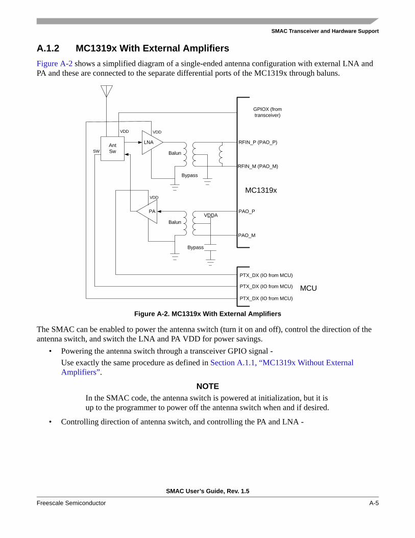
A.1.2 MC1319x With External AmplifiersFigure A-2 shows a simplified diagram of a single-ended antenna configuration with external LNA and PA and these are connected to the separate differential ports of the MC1319x through baluns.
Figure A-2. MC1319x With External Amplifiers
The SMAC can be enabled to power the antenna switch (turn it on and off), control the direction of the antenna switch, and switch the LNA and PA VDD for power savings.
• Powering the antenna switch through a transceiver GPIO signal -Use exactly the same procedure as defined in Section A.1.1, “MC1319x Without External Amplifiers”.
NOTEIn the SMAC code, the antenna switch is powered at initialization, but it is up to the programmer to power off the antenna switch when and if desired.
• Controlling direction of antenna switch, and controlling the PA and LNA -
Balun
Bypass
RFIN_P (PAO_P)
RFIN_M (PAO_M)
PAO_P
PAO_M
MC1319x
AntSw
Balun
VDD
VDDA
Bypass
LNA
PA
VDD
VDD
SW
GPIOX (fromtransceiver)
PTX_DX (IO from MCU)
PTX_DX (IO from MCU)
PTX_DX (IO from MCU)
MCU
SMAC Transceiver and Hardware Support
SMAC User’s Guide, Rev. 1.5
A-6 Freescale Semiconductor
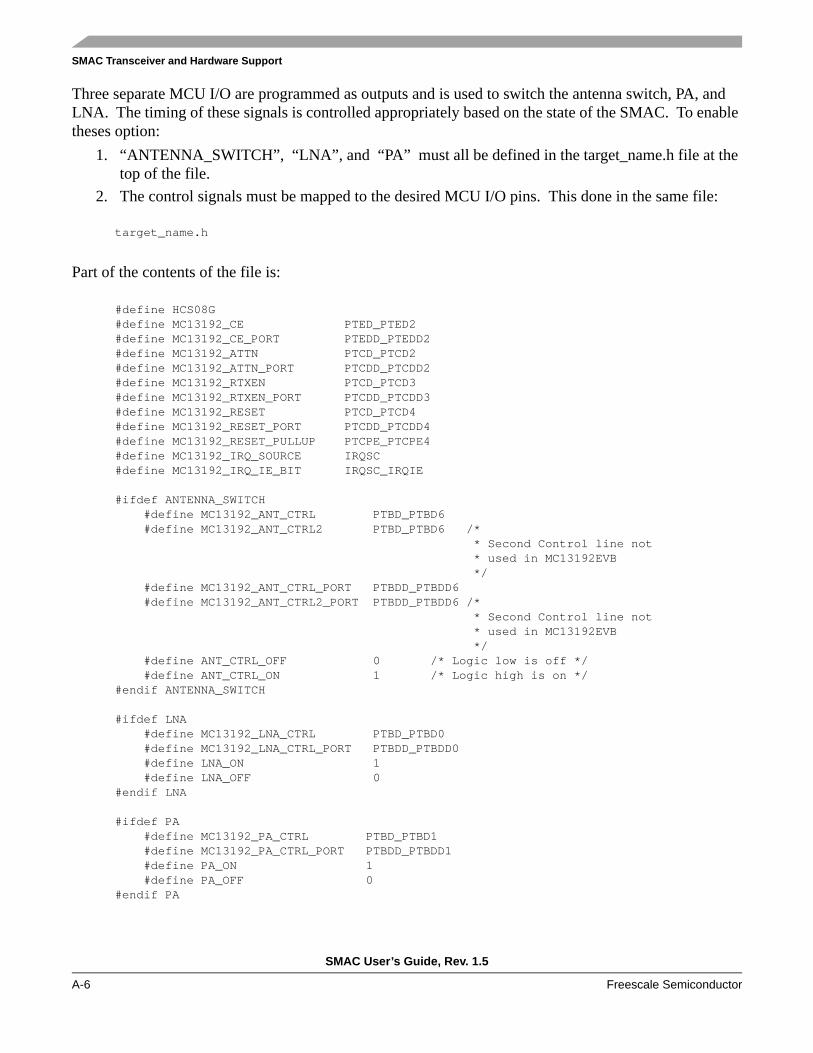
Three separate MCU I/O are programmed as outputs and is used to switch the antenna switch, PA, and LNA. The timing of these signals is controlled appropriately based on the state of the SMAC. To enable theses option:
1. “ANTENNA_SWITCH”, “LNA”, and “PA” must all be defined in the target_name.h file at the top of the file.
2. The control signals must be mapped to the desired MCU I/O pins. This done in the same file:
target_name.h
Part of the contents of the file is:
#define HCS08G#define MC13192_CE PTED_PTED2 #define MC13192_CE_PORT PTEDD_PTEDD2 #define MC13192_ATTN PTCD_PTCD2#define MC13192_ATTN_PORT PTCDD_PTCDD2#define MC13192_RTXEN PTCD_PTCD3#define MC13192_RTXEN_PORT PTCDD_PTCDD3#define MC13192_RESET PTCD_PTCD4#define MC13192_RESET_PORT PTCDD_PTCDD4#define MC13192_RESET_PULLUP PTCPE_PTCPE4#define MC13192_IRQ_SOURCE IRQSC#define MC13192_IRQ_IE_BIT IRQSC_IRQIE
#ifdef ANTENNA_SWITCH #define MC13192_ANT_CTRL PTBD_PTBD6 #define MC13192_ANT_CTRL2 PTBD_PTBD6 /* * Second Control line not * used in MC13192EVB */ #define MC13192_ANT_CTRL_PORT PTBDD_PTBDD6 #define MC13192_ANT_CTRL2_PORT PTBDD_PTBDD6 /* * Second Control line not * used in MC13192EVB */ #define ANT_CTRL_OFF 0 /* Logic low is off */ #define ANT_CTRL_ON 1 /* Logic high is on */#endif ANTENNA_SWITCH
#ifdef LNA #define MC13192_LNA_CTRL PTBD_PTBD0 #define MC13192_LNA_CTRL_PORT PTBDD_PTBDD0 #define LNA_ON 1 #define LNA_OFF 0#endif LNA
#ifdef PA #define MC13192_PA_CTRL PTBD_PTBD1 #define MC13192_PA_CTRL_PORT PTBDD_PTBDD1 #define PA_ON 1 #define PA_OFF 0#endif PA

SMAC Transceiver and Hardware Support
SMAC User’s Guide, Rev. 1.5
Freescale Semiconductor A-7
In this code with the “ANTENNA_SWITCH”, “LNA”, and “PA” compile options enabled, the MC13192_ANT_CTRL is defined as Port B, Bit 6, The MC13192_LNA_CTRL is defined as Port B, Bit 0, and MC13192_PA_CTRL is defined as Port B, Bit 1. The state of the control signal for “on” versus “off” can be selected via the “ON” and “OFF” define statements.
A.2 MC1320x and MC1321x RF ConfigurationsThe MC1320x and MC1321x families use the same transceiver and RF interface. Both these families have the advantage of a single-port mode where there is a TX/RX switch onboard the device. These devices also have a second port that allows dual port operation similar to the MC1319x family, and this mode also allows use of external LNA and PA.
NOTEIt is suggested that the user review the proper Reference Manual for the MC1302x and MC1321x device to understand its RF configuration and capabilities. Specifically refer to the chapter on System Considerations.
A.2.1 MC1320x or MC1321x Without External ComponentsFigure A-3 shows a simplified diagram of a single-ended antenna connected to the bidirectional single differential port on the MC1320x or MC1321x.
Figure A-3. MC1320x or MC1321x Without External Amplifiers
• RFIN_X are bidirectional differential signals• CT_bias is a programmable control pin and can switch the required reference voltage to a balun
based on the RX or TX activity of the radio• PAO_X are differential outputs only and are not used in single-port mode
Balun
Bypass
RFIN_P (PAO_P)
RFIN_M (PAO_M)
CT_Bias
PAO_P
PAO_M
MC1320x/MC1321x

SMAC Transceiver and Hardware Support
SMAC User’s Guide, Rev. 1.5
A-8 Freescale Semiconductor
• Dual port mode with the bidirectional interface disabled is the default mode and must be over-programmed in the SMAC
Therefore, for the SMAC:• The device must be initiated to single-port mode through over-programming of the default
conditions• The MCU GPIO to power an external antenna switch is not required• The SMAC antenna switch function is not required
The SMAC modification for single-port mode requires only editing of the target radio initialization file:1. The “ANTENNA_SWITCH”, “LNA”, and “PA” macros are not defined.2. A transceiver GPIO does not need to be programmed as a power source for an external antenna
switch.3. The target radio initialization file is:
target_name.c
Typical contents of the file are:
#include “drivers.h”#include “target_name.h”
void RadioInit(void) { SPIDrvWrite(0x11,0x80FF); /* Eliminate Unlock Conditions due to L01 */ SPIDrvWrite(0x1B,0x8000); /* Disable TC1. */ SPIDrvWrite(0x1D,0x8000); /* Disable TC2. */ SPIDrvWrite(0x1F,0x8000); /* Disable TC3. */ SPIDrvWrite(0x21,0x8000); /* Disable TC4. */ SPIDrvWrite(0x07,0x5C00); /* Enable CLKo in Doze, enable single-port and CT_bias */ SPIDrvWrite(0x0C,0x0381); /* IRQ pull-up disable. */ SPIDrvWrite(0x04,0xA08D); /* New cal value */ SPIDrvWrite(0x05,0x8351); /* Acoma, TC1, Doze, ATTN masks, LO1, CRC */ SPIDrvWrite(0x06,0x4720); /* CCA, TX, RX, energy detect */ SPIDrvWrite(0x0B,0xC0FE); /* Advance the state variable to Idle */ gu8RTxMode = IDLE_MODE;}
In this code:• Writing to Register 0x0C does not define a GPIO pin as a antenna switch function• Writing to Register 0x07; sets Bit 12 enabling single port mode, sets Bit 14 enabling the CT_Bias
drive, and clears Bit 13 so that CT_bias is high for TX as required by the balun and chip (if Bit 13 is set, the sense of CT_bias is inverted)

SMAC Transceiver and Hardware Support
SMAC User’s Guide, Rev. 1.5
Freescale Semiconductor A-9
A.2.2 MC13120x or MC1321x With External AmplifiersFigure A-4 shows a simplified diagram of a single-ended antenna configuration with external LNA and PA and these are connected to the separate differential ports of the MC1320x or MC1321x through baluns.
Figure A-4. MC1320x or MC1321x With External Amplifiers
The SMAC can be enabled to power the antenna switch (turn it on and off) and switch the LNA and PA VDD for power savings.
The transceiver must be programmed to provide the antenna switch signal from the CT_Bias pin.• Powering the antenna switch through a transceiver GPIO signal and enabling the CT_Bias
(transceiver must be in dual port RF mode)-
A transceiver GPIO is programmed as an output and set to a high state, and the dual port RF mode and CT_bias is enabled through the target radio initialization file. This file is:
target_name.c
Typical contents of the file are:
#include “drivers.h”#include “target_name.h”
Balun
Bypass
RFIN_P (PAO_P)
RFIN_M (PAO_M)
PAO_P
PAO_M
MC1320x/MC1321xTransceiver
AntSw
Balun
VDD
VDDA
Bypass
LNA
PA
VDD
VDD
SW
GPIOX (fromtransceiver)
PTX_DX (IO from MCU)
PTX_DX (IO from MCU)MCU
CT_Bias
SMAC Transceiver and Hardware Support
SMAC User’s Guide, Rev. 1.5
A-10 Freescale Semiconductor
extern UINT8 gu8RTxMode;
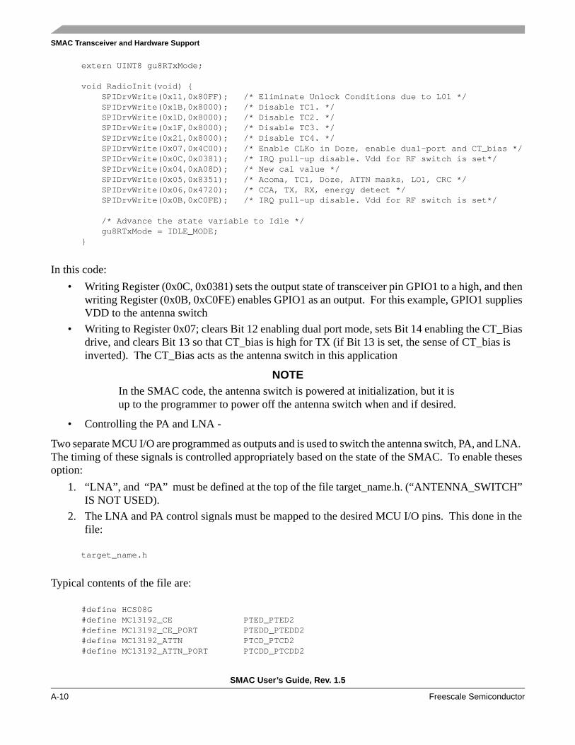
void RadioInit(void) { SPIDrvWrite(0x11,0x80FF); /* Eliminate Unlock Conditions due to L01 */ SPIDrvWrite(0x1B,0x8000); /* Disable TC1. */ SPIDrvWrite(0x1D,0x8000); /* Disable TC2. */ SPIDrvWrite(0x1F,0x8000); /* Disable TC3. */ SPIDrvWrite(0x21,0x8000); /* Disable TC4. */ SPIDrvWrite(0x07,0x4C00); /* Enable CLKo in Doze, enable dual-port and CT_bias */ SPIDrvWrite(0x0C,0x0381); /* IRQ pull-up disable. Vdd for RF switch is set*/ SPIDrvWrite(0x04,0xA08D); /* New cal value */ SPIDrvWrite(0x05,0x8351); /* Acoma, TC1, Doze, ATTN masks, LO1, CRC */ SPIDrvWrite(0x06,0x4720); /* CCA, TX, RX, energy detect */ SPIDrvWrite(0x0B,0xC0FE); /* IRQ pull-up disable. Vdd for RF switch is set*/
/* Advance the state variable to Idle */ gu8RTxMode = IDLE_MODE;}
In this code:• Writing Register (0x0C, 0x0381) sets the output state of transceiver pin GPIO1 to a high, and then
writing Register (0x0B, 0xC0FE) enables GPIO1 as an output. For this example, GPIO1 supplies VDD to the antenna switch
• Writing to Register 0x07; clears Bit 12 enabling dual port mode, sets Bit 14 enabling the CT_Bias drive, and clears Bit 13 so that CT_bias is high for TX (if Bit 13 is set, the sense of CT_bias is inverted). The CT_Bias acts as the antenna switch in this application
NOTEIn the SMAC code, the antenna switch is powered at initialization, but it is up to the programmer to power off the antenna switch when and if desired.
• Controlling the PA and LNA -
Two separate MCU I/O are programmed as outputs and is used to switch the antenna switch, PA, and LNA. The timing of these signals is controlled appropriately based on the state of the SMAC. To enable theses option:
1. “LNA”, and “PA” must be defined at the top of the file target_name.h. (“ANTENNA_SWITCH” IS NOT USED).
2. The LNA and PA control signals must be mapped to the desired MCU I/O pins. This done in the file:
target_name.h
Typical contents of the file are:
#define HCS08G#define MC13192_CE PTED_PTED2 #define MC13192_CE_PORT PTEDD_PTEDD2 #define MC13192_ATTN PTCD_PTCD2#define MC13192_ATTN_PORT PTCDD_PTCDD2

SMAC Transceiver and Hardware Support
SMAC User’s Guide, Rev. 1.5
Freescale Semiconductor A-11
#define MC13192_RTXEN PTCD_PTCD3#define MC13192_RTXEN_PORT PTCDD_PTCDD3#define MC13192_RESET PTCD_PTCD4#define MC13192_RESET_PORT PTCDD_PTCDD4#define MC13192_RESET_PULLUP PTCPE_PTCPE4#define MC13192_IRQ_SOURCE IRQSC#define MC13192_IRQ_IE_BIT IRQSC_IRQIE
#ifdef LNA #define MC13192_LNA_CTRL PTBD_PTBD0 #define MC13192_LNA_CTRL_PORT PTBDD_PTBDD0 #define LNA_ON 1 #define LNA_OFF 0#endif LNA
#ifdef PA #define MC13192_PA_CTRL PTBD_PTBD1 #define MC13192_PA_CTRL_PORT PTBDD_PTBDD1 #define PA_ON 1 #define PA_OFF 0#endif PA
In this code with the “LNA” and “PA” compile options enabled, the MC13192_LNA_CTRL is defined as Port B, Bit 0, and MC13192_PA_CTRL is defined as Port B, Bit 1. The state of the control signal for “on” versus “off” can be selected via the “ON” and “OFF” define statements.

SMAC Transceiver and Hardware Support
SMAC User’s Guide, Rev. 1.5
A-12 Freescale Semiconductor