Embed Size (px)
Citation preview

Programming Flash Devices
IntroductionThis document provides an overview of the various programming options available for the Actelflash families. The electronic version of this document includes active links to all programmingresources, which are available at http://www.actel.com/products/hardware/default.aspx. For Actelantifuse devices, refer to the Programming Antifuse Devices document.
Summary of Programming Support FlashPro3 is a high-performance in-system programming (ISP) tool targeted at the latestgeneration of low-power flash devices offered by Actel: Fusion, IGLOO,® and ProASIC®3, includingARM®-enabled devices. FlashPro3 offers extremely high performance through the use of USB 2.0, ishigh-speed compliant for full use of the 480 Mbps bandwidth, and can program ProASIC3 devicesin under 30 seconds. Powered exclusively via USB, FlashPro3 provides a VPUMP voltage of 3.3 V forprogramming these devices.
Silicon Sculptor 3 is an easy-to-use, single-site programming tool for Actel FPGAs that delivers highdata throughput and promotes ease of use while lowering the overall cost of ownership. SiliconSculptor 3 includes a high-speed USB 2.0 interface that allows a customer to connect as many as 12programmers to a single PC. Furthermore, Silicon Sculptor 3 is compatible with adapter modulesfrom Silicon Sculptor II, thereby preserving a customer's investment and enabling a seamlessupgrade to this latest generation of the tool.
For details of programmer support for each device, refer to Table 6 on page 10.
Figure 1 • FlashPro Programming Setup
FlashProSoftware FlashPro3
JTAGProASIC3/E
PDB File withSecurity Settings
v1.2 1

Programming Flash Devices
Programming Support in Flash Devices The flash families listed in Table 1 support flash in-system programming and the functionsdescribed in this document.
IGLOO TerminologyIn documentation, the terms IGLOO families and IGLOO devices refer to all of the IGLOO productsas listed in Table 1. Where the information applies to only one family or limited devices, theseexclusions will be explicitly stated.
ProASIC3 TerminologyIn documentation, the terms ProASIC3 families and ProASIC3 devices refer to all of the ProASIC3families as listed in Table 1. Where the information applies to only one family or limited devices,these exclusions will be explicitly stated.
To further understand the differences between the IGLOO and ProASIC3 families, refer to theIndustry’s Lowest Power FPGAs Portfolio.
Table 1 • Low-Power Flash Families
Product Line Family* Description
Fusion Fusion Mixed-signal FPGA integrating ProASIC3 FPGA fabric, programmableanalog block, support for ARM® Cortex™-M1 soft processors and flashmemory into a monolithic device
IGLOO IGLOO Ultra-low-power 1.2 V to 1.5 V FPGAs with Flash*Freeze technology
IGLOOe Higher density IGLOO FPGAs with six PLLs and additional I/O standards
IGLOO PLUS IGLOO FPGAs with enhanced I/O capabilities
ProASIC3 ProASIC3 Low-power, high-performance 1.5 V FPGAs
ProASIC3E Higher density ProASIC3 FPGAs with six PLLs and additional I/O standards
ProASIC3L ProASIC3 FPGAs supporting 1.2 V to 1.5 V with Flash*Freeze technology
Automotive ProASIC3 ProASIC3 FPGAs qualified for automotive applications
Military ProASIC3/EL Military temperature A3PE600L, A3P1000, and A3PE3000L
RT ProASIC3 Radiation-tolerant RT3PE600L and RT3PE3000L
ProASIC ProASIC First generation ProASIC devices
ProASICPLUS Second generation ProASIC devices
Note: *The family names link to the appropriate datasheet, including product brief, DC and switchingcharacteristics, and packaging information.
2 v1.2

Programming Flash Devices
General Flash Programming Information
Programming BasicsWhen choosing a programming solution, there are a number of options available. This sectionprovides a brief overview of those options. The next sections provide more detail on those optionsas they apply to Actel FPGAs.
Reprogrammable or One-Time-Programmable (OTP)Depending on the technology chosen, devices may be reprogrammable or one-time-programmable. As the name implies, a reprogrammable device can be programmed many times.Generally, the contents of such a device will be completely overwritten when it is reprogrammed.All Actel flash devices are reprogrammable.
An OTP device is programmable one time only. Once programmed, no more changes can be madeto the contents. Actel flash devices provide the option of disabling the reprogrammability forsecurity purposes. This combines the convenience of reprogrammability during design verificationwith the security of an OTP technology for highly sensitive designs.
Device Programmer or In-System ProgrammingThere are two fundamental ways to program an FPGA: using a device programmer or, if thetechnology permits, using in-system programming. A device programmer is a piece of equipment ina lab or on the production floor that is used for programming devices. The devices are placed intoa socket mounted in a programming adapter module, and the appropriate electrical interface isapplied. The device can then be placed on the board. A typical programmer, used duringdevelopment, programs a single device at a time and is referred to as a single-site engineeringprogrammer.
With ISP, the device is already mounted onto the board when programming occurs, most typicallyvia the JTAG pins. The JTAG pins can be controlled either by an on-board resource, such as amicroprocessor, or by an off-board programmer through a header connection. Once mounted, itcan be programmed repeatedly. If the application requires it, the system can be designed toreprogram itself using a microprocessor, without the use of any external programmer.
For production, high-volume multi-site production programmers handle designs that requiredevice programmers. In addition, Actel can preprogram devices for production, negating the needfor further programming. This service is referred to as in-house programming (IHP).
Live at Power-Up (LAPU) or Boot PROMUtilizing the technology of the FPGA significantly impacts board-level power-up considerations.Some technologies are nonvolatile and are considered functional, or "live," as soon as powerreaches the operational level. All Actel FPGA technologies are live at power-up. By contrast, SRAMtechnology is volatile, and devices built using SRAM cells lose their contents when power cyclingoccurs. These devices must be reprogrammed every time power is applied. Such a design mustinclude nonvolatile storage for the contents as well as the means to reprogram. There is a delaybefore SRAM devices are functional; other parts of the board must come alive first to reprogramthese types of FPGAs. Therefore, such devices can never be part of critical boot circuits.
Design SecurityDesign security is a growing concern for systems designers. The choice of programmingmethodology and technology affects system security. Use of Actel programming technology is themost secure option available, providing much better protection than SRAM-based devices andASICs. Actel provides a number of ways to ensure designs are protected. General information ondesign security can be found on the Actel website:
http://www.actel.com/products/solutions/security/default.aspx
v1.2 3
Programming Flash Devices
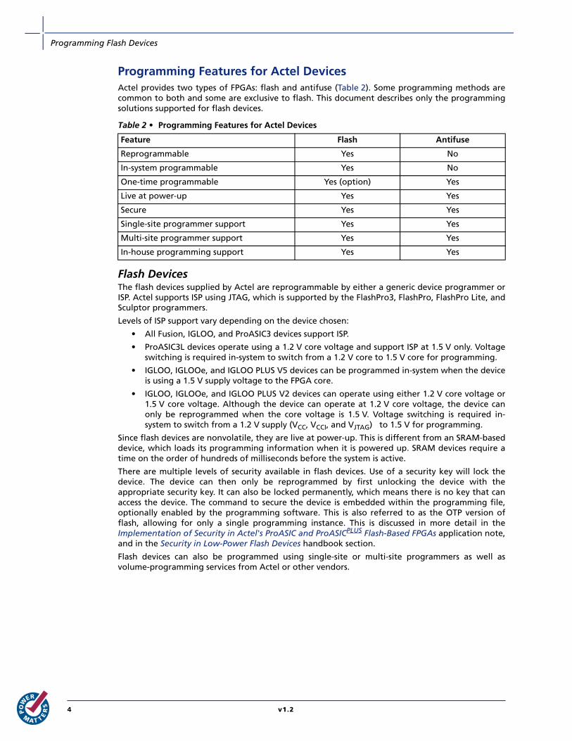
Programming Features for Actel Devices Actel provides two types of FPGAs: flash and antifuse (Table 2). Some programming methods arecommon to both and some are exclusive to flash. This document describes only the programmingsolutions supported for flash devices.
Flash DevicesThe flash devices supplied by Actel are reprogrammable by either a generic device programmer orISP. Actel supports ISP using JTAG, which is supported by the FlashPro3, FlashPro, FlashPro Lite, andSculptor programmers.
Levels of ISP support vary depending on the device chosen:
• All Fusion, IGLOO, and ProASIC3 devices support ISP.
• ProASIC3L devices operate using a 1.2 V core voltage and support ISP at 1.5 V only. Voltageswitching is required in-system to switch from a 1.2 V core to 1.5 V core for programming.
• IGLOO, IGLOOe, and IGLOO PLUS V5 devices can be programmed in-system when the deviceis using a 1.5 V supply voltage to the FPGA core.
• IGLOO, IGLOOe, and IGLOO PLUS V2 devices can operate using either 1.2 V core voltage or1.5 V core voltage. Although the device can operate at 1.2 V core voltage, the device canonly be reprogrammed when the core voltage is 1.5 V. Voltage switching is required in-system to switch from a 1.2 V supply (VCC, VCCI, and VJTAG) to 1.5 V for programming.
Since flash devices are nonvolatile, they are live at power-up. This is different from an SRAM-baseddevice, which loads its programming information when it is powered up. SRAM devices require atime on the order of hundreds of milliseconds before the system is active.
There are multiple levels of security available in flash devices. Use of a security key will lock thedevice. The device can then only be reprogrammed by first unlocking the device with theappropriate security key. It can also be locked permanently, which means there is no key that canaccess the device. The command to secure the device is embedded within the programming file,optionally enabled by the programming software. This is also referred to as the OTP version offlash, allowing for only a single programming instance. This is discussed in more detail in theImplementation of Security in Actel's ProASIC and ProASICPLUS Flash-Based FPGAs application note,and in the Security in Low-Power Flash Devices handbook section.
Flash devices can also be programmed using single-site or multi-site programmers as well asvolume-programming services from Actel or other vendors.
Table 2 • Programming Features for Actel Devices
Feature Flash Antifuse
Reprogrammable Yes No
In-system programmable Yes No
One-time programmable Yes (option) Yes
Live at power-up Yes Yes
Secure Yes Yes
Single-site programmer support Yes Yes
Multi-site programmer support Yes Yes
In-house programming support Yes Yes
4 v1.2
Programming Flash Devices
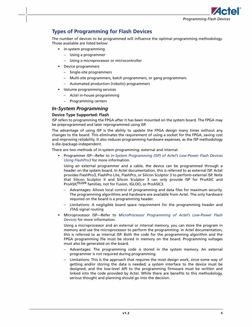
Types of Programming for Flash DevicesThe number of devices to be programmed will influence the optimal programming methodology.Those available are listed below:
• In-system programming
– Using a programmer
– Using a microprocessor or microcontroller
• Device programmers
– Single-site programmers
– Multi-site programmers, batch programmers, or gang programmers
– Automated production (robotic) programmers
• Volume programming services
– Actel in-house programming
– Programming centers
In-System ProgrammingDevice Type Supported: FlashISP refers to programming the FPGA after it has been mounted on the system board. The FPGA maybe preprogrammed and later reprogrammed using ISP.
The advantage of using ISP is the ability to update the FPGA design many times without anychanges to the board. This eliminates the requirement of using a socket for the FPGA, saving costand improving reliability. It also reduces programming hardware expenses, as the ISP methodologyis die-/package-independent.
There are two methods of in-system programming: external and internal.
• Programmer ISP—Refer to In-System Programming (ISP) of Actel’s Low-Power Flash DevicesUsing FlashPro3 for more information.
Using an external programmer and a cable, the device can be programmed through aheader on the system board. In Actel documentation, this is referred to as external ISP. Actelprovides FlashPro3, FlashPro Lite, FlashPro, or Silicon Sculptor 3 to perform external ISP. Notethat Silicon Sculptor II and Silicon Sculptor 3 can only provide ISP for ProASIC andProASICPLUS® families, not for Fusion, IGLOO, or ProASIC3.
– Advantages: Allows local control of programming and data files for maximum security.The programming algorithms and hardware are available from Actel. The only hardwarerequired on the board is a programming header.
– Limitations: A negligible board space requirement for the programming header andJTAG signal routing
• Microprocessor ISP—Refer to MicroProcessor Programming of Actel’s Low-Power FlashDevices for more information.
Using a microprocessor and an external or internal memory, you can store the program inmemory and use the microprocessor to perform the programming. In Actel documentation,this is referred to as internal ISP. Both the code for the programming algorithm and theFPGA programming file must be stored in memory on the board. Programming voltagesmust also be generated on the board.
– Advantages: The programming code is stored in the system memory. An externalprogrammer is not required during programming.
– Limitations: This is the approach that requires the most design work, since some way ofgetting and/or storing the data is needed; a system interface to the device must bedesigned; and the low-level API to the programming firmware must be written andlinked into the code provided by Actel. While there are benefits to this methodology,serious thought and planning should go into the decision.
v1.2 5

Programming Flash Devices
Device ProgrammersDevice Type Supported: Flash and AntifuseDevice programmers are used to program a device before it is mounted on the system board.
The advantage of using device programmers is that no programming hardware is required on thesystem board. Therefore, no additional components or board space are required.
If devices are to be reprogrammed multiple times, or if the quantity of devices to be programmedis relatively low, a single-site device programmer is the simplest solution. For applications in whichdesign security is paramount (often the case in military or space designs), the use of on-siteprograming maintains design security at all times.
Adapter modules are purchased with the programmers to support the FPGA packages used. TheFPGA is placed in the adapter module and the programming software is run from a PC. Actelsupplies the programming software for all of the Actel programmers. The software allows for theselection of the correct die/package and programming files. It will then program and verify thedevice.
• Single-site programmers
A single-site programmer programs one device at a time. Actel offers Silicon Sculptor 3 as asingle-site programmer.
– Advantages: Lower cost than multi-site programmers. No additional overhead forprogramming on the system board. Allows local control of programming and data filesfor maximum security. Allows on-demand programming on-site.
– Limitations: Only programs one device at a time.
• Multi-site programmers
Often referred to as batch or gang programmers, multi-site programmers can programmultiple devices at the same time using the same programming file. This is often used forlarge volume programming and by programming houses. The sites often have independentprocessors and memory enabling the sites to operate concurrently, meaning each site maystart programming the same file independently. This enables the operator to change onedevice while the other sites continue programming, which increases throughput. Multipleadapter modules for the same package are required when using a multi-site programmer.Silicon Sculptor I, II, and 3 programmers can be cascaded to program multiple devices in achain. Multi-site programmers can also be purchased from BP Microsystems.
– Advantages: Provides the capability of programming multiple devices at the same time.No additional overhead for programming on the system board. Allows local control ofprogramming and data files for maximum security.
– Limitations: More expensive than a single-site programmer
• Automated production (robotic) programmers
Automated production programmers are based on multi-site programmers. They consist of alarge input tray holding multiple parts and a robotic arm to select and place parts intoappropriate programming sockets automatically. When the programming of the parts iscomplete, the parts are removed and placed in a finished tray. The automated programmersare often used in volume programming houses to program parts for which theprogramming time is small.
6 v1.2

Programming Flash Devices
Volume Programming ServicesDevice Type Supported: Flash and AntifuseOnce the design is stable for applications with large production volumes, preprogrammed devicescan be purchased. Table 3 describes the volume programming services.
Advantages: As programming is outsourced, this solution is easier to implement than creating asubstantial in-house programming capability. As programming houses specialize in large-volumeprogramming, this is often the most cost-effective solution.
Limitations: There are some logistical issues with the use of a programming service provider, such asthe transfer of programming files and the approval of first articles. By definition, the programmingfile must be released to a third-party programming house. Nondisclosure agreements (NDAs) canbe signed to help ensure data protection; however, for extremely security-conscious designs, thismay not be an option.
• Actel In-House Programming
When purchasing Actel devices in volume, IHP can be requested as part of the purchase. Ifthis option is chosen, there is a small cost adder for each device programmed. Each device ismarked with a special mark to distinguish it from blank parts. Programming files for thedesign will be sent to Actel. Sample parts with the design programmed, First Articles, will bereturned for customer approval. Once approval of First Articles has been received, Actel willproceed with programming the remainder of the order. To request Actel IHP, contact yourlocal Actel representative.
• Distributor Programming Centers
If purchases are made through a distributor, many distributors will provide programming fortheir customers. Consult with your preferred distributor about this option.
• Independent Programming Centers
There are many programming centers that specialize only in programming but are notdirectly affiliated with Actel or our distributors. These programming centers must follow theguidelines for programming Actel devices and use certified programmers to program Acteldevices. Actel does not have recommendations for external programming centers.
Table 3 • Volume Programming Services
Programmer Vendor Availability
In-House Programming Actel Contact Actel Sales
Distributor Programming Centers Memec Unique Contact Distribution
Independent Programming Centers Various Contact Vendor
v1.2 7
Programming Flash Devices
Programming Solutions Details for the available programmers can be found in the programmer user's guides listed in the"Related Documents" section on page 14. Refer to Table 6 on page 10 for more informationconcerning programming solutions.
All of the programmers except the FlashPro3, FlashPro Lite, and FlashPro require adapter modules,which are designed to support device packages. The modules are all listed on the Actel website athttp://www.actel.com/products/hardware/program_debug/ss/modules.aspx. They are not listed inthis document, since this list is updated frequently with new package options and any upgradesrequired to improve programming yield or support new families.
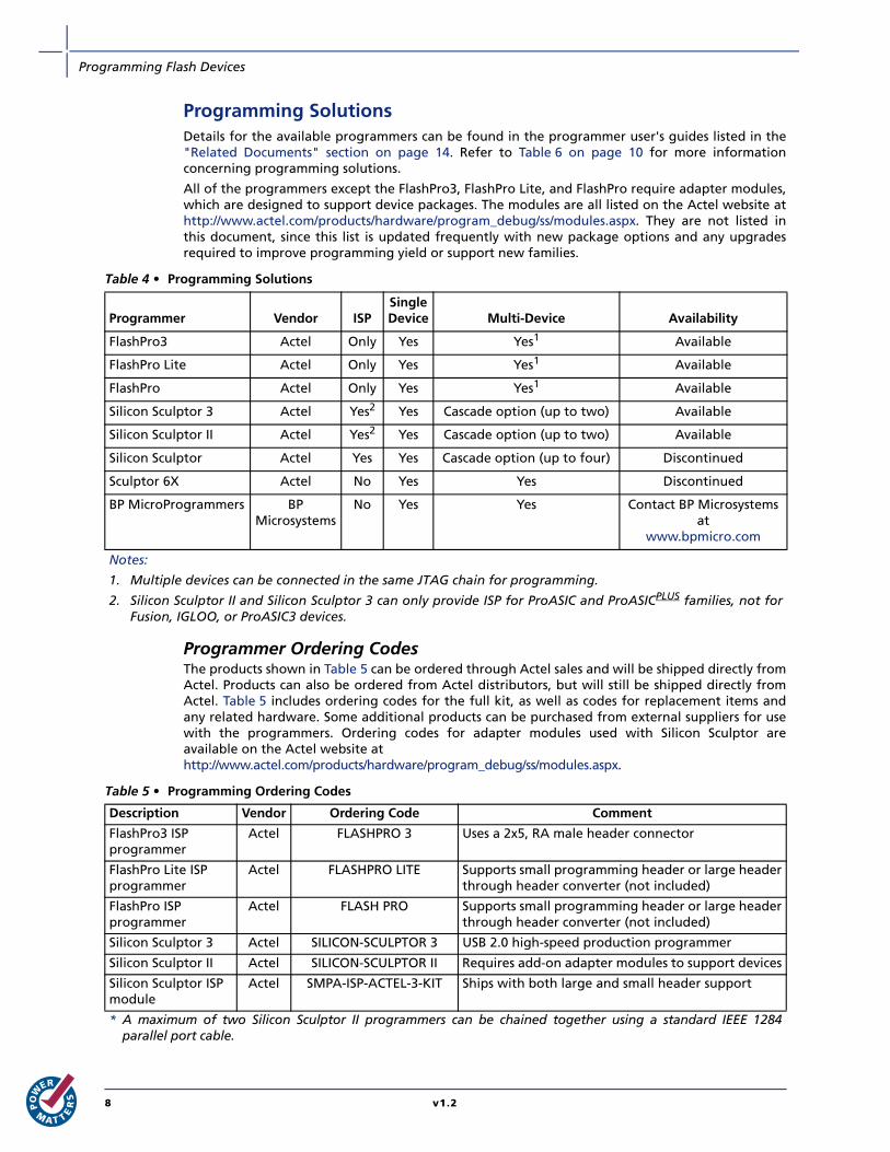
Programmer Ordering Codes The products shown in Table 5 can be ordered through Actel sales and will be shipped directly fromActel. Products can also be ordered from Actel distributors, but will still be shipped directly fromActel. Table 5 includes ordering codes for the full kit, as well as codes for replacement items andany related hardware. Some additional products can be purchased from external suppliers for usewith the programmers. Ordering codes for adapter modules used with Silicon Sculptor areavailable on the Actel website athttp://www.actel.com/products/hardware/program_debug/ss/modules.aspx.
Table 4 • Programming Solutions
Programmer Vendor ISPSingleDevice Multi-Device Availability
FlashPro3 Actel Only Yes Yes1 Available
FlashPro Lite Actel Only Yes Yes1 Available
FlashPro Actel Only Yes Yes1 Available
Silicon Sculptor 3 Actel Yes2 Yes Cascade option (up to two) Available
Silicon Sculptor II Actel Yes2 Yes Cascade option (up to two) Available
Silicon Sculptor Actel Yes Yes Cascade option (up to four) Discontinued
Sculptor 6X Actel No Yes Yes Discontinued
BP MicroProgrammers BP Microsystems
No Yes Yes Contact BP Microsystems at
www.bpmicro.com
Notes:
1. Multiple devices can be connected in the same JTAG chain for programming.
2. Silicon Sculptor II and Silicon Sculptor 3 can only provide ISP for ProASIC and ProASICPLUS families, not forFusion, IGLOO, or ProASIC3 devices.
Table 5 • Programming Ordering Codes
Description Vendor Ordering Code Comment
FlashPro3 ISPprogrammer
Actel FLASHPRO 3 Uses a 2x5, RA male header connector
FlashPro Lite ISP programmer
Actel FLASHPRO LITE Supports small programming header or large headerthrough header converter (not included)
FlashPro ISPprogrammer
Actel FLASH PRO Supports small programming header or large headerthrough header converter (not included)
Silicon Sculptor 3 Actel SILICON-SCULPTOR 3 USB 2.0 high-speed production programmer
Silicon Sculptor II Actel SILICON-SCULPTOR II Requires add-on adapter modules to support devices
Silicon Sculptor ISPmodule
Actel SMPA-ISP-ACTEL-3-KIT Ships with both large and small header support
* A maximum of two Silicon Sculptor II programmers can be chained together using a standard IEEE 1284parallel port cable.
8 v1.2
Programming Flash Devices
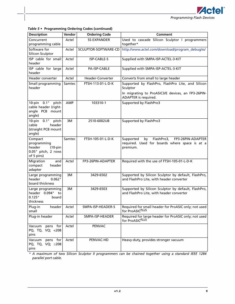
Concurrentprogramming cable
Actel SS-EXPANDER Used to cascade Silicon Sculptor I programmerstogether*
Software for Silicon Sculptor
Actel SCULPTOR-SOFTWARE-CD http://www.actel.com/download/program_debug/ss/
ISP cable for smallheader
Actel ISP-CABLE-S Supplied with SMPA-ISP-ACTEL-3-KIT
ISP cable for largeheader
Actel PA-ISP-CABLE Supplied with SMPA-ISP-ACTEL-3-KIT
Header converter Actel Header-Converter Converts from small to large header
Small programmingheader
Samtec FTSH-113-01-L-D-K Supported by FlashPro, FlashPro Lite, and SiliconSculptor
In migrating to ProASIC3/E devices, an FP3-26PIN-ADAPTER is required.
10-pin 0.1" pitchcable header (right-angle PCB mountangle)
AMP 103310-1 Supported by FlashPro3
10-pin 0.1" pitchcable header(straight PCB mountangle)
3M 2510-6002UB Supported by FlashPro3
Compactprogrammingheader (10-pin0.05" pitch, 2 rowsof 5 pins)
Samtec FTSH-105-01-L-D-K Supported by FlashPro3, FP3-26PIN-ADAPTERrequired. Used for boards where space is at apremium.
Migration andcompact headeradapter
Actel FP3-26PIN-ADAPTER Required with the use of FTSH-105-01-L-D-K
Large programmingheader 0.062"board thickness
3M 3429-6502 Supported by Silicon Sculptor by default, FlashPro,and FlashPro Lite, with header converter
Large programmingheader 0.094" to0.125" boardthickness
3M 3429-6503 Supported by Silicon Sculptor by default, FlashPro,and FlashPro Lite, with header converter
Plug-in headersmall
Actel SMPA-ISP-HEADER-S Required for small header for ProASIC only; not usedfor ProASICPLUS
Plug-in header Actel SMPA-ISP-HEADER Required for large header for ProASIC only; not usedfor ProASICPLUS
Vacuum pens forPQ, TQ, VQ; <208pins
Actel PENVAC
Vacuum pens forPQ, TQ, VQ; ≥208pins
Actel PENVAC-HD Heavy-duty, provides stronger vacuum
Table 5 • Programming Ordering Codes (continued)
Description Vendor Ordering Code Comment
* A maximum of two Silicon Sculptor II programmers can be chained together using a standard IEEE 1284parallel port cable.
v1.2 9

Programming Flash Devices
Programmer Device Support Refer to Table 6 to determine which general-purpose flash devices have programmer devicesupport. To learn more about the different Actel families, refer to the Actel website:http://www.actel.com/products/devices.aspx.
Data in Table 6 also applies to ARM-enabled M7 device versions of Fusion, IGLOO, and ProASIC3devices. Refer to the appropriate family datasheets for information on die/package combinationsavailable as ARM-enabled versions.
Table 6 • Programmer Device Support
ActelFamily Device
ARM-Enabled
SiliconSculptor
SiliconSculptor
6X
SiliconSculptor
II
SiliconSculptor
3 FlashProFlashPro
Lite FlashPro3
Fusion AFS090 No No Yes.
No ISPsupport.
Yes.
No ISPsupport.
No No Yes.ISP
supportAFS250
AFS600 ✓
AFS1500 ✓
IGLOO AGL015 No No Yes.
No ISPsupport.
Yes.
No ISPsupport.
No No Yes.ISP
support.AGL030
AGL060
AGL125
AGL250 ✓
AGL600 ✓
AGL1000 ✓
IGLOOe AGLE600
AGLE3000
✓ No No Yes.
No ISPsupport
Yes.
No ISPsupport.
No No Yes.ISP
support✓
IGLOO PLUS AGLP030 No No Yes.
No ISP support
Yes.
No ISP support.
No No Yes.ISP
supportAGLP060
AGLP125
ProASIC3L A3P250L ✓ No No Yes.
No ISP support.
Yes.
No ISP support.
No No Yes.
ISP support.
A3P600L ✓
A3P1000L ✓
A3PE3000L ✓
ProASIC3 A3P015 No No Yes.
No ISPsupport.
Yes.
No ISPsupport.
No No Yes.ISP
support.A3P030
A3P060
A3P125
A3P250 ✓
A3P400 ✓
A3P600 ✓
A3P1000 ✓
ProASIC3E A3PE600 ✓ No No Yes.
No ISPsupport.
Yes.
No ISPsupport.
No No Yes.ISP
support.A3PE1500 ✓
A3PE3000 ✓
* Refer to the "Certified Programming Solutions" section on page 11 for more information onprogrammer support.
10 v1.2

Programming Flash Devices
Certified Programming Solutions The Actel-certified programmers for flash devices are FlashPro3, FlashPro Lite, FlashPro, SiliconSculptor I and II, and any programmer that is built by BP Microsystems. All other programmers areconsidered noncertified programmers.
• FlashPro3, FlashPro Lite, FlashPro
The Actel family of FlashPro device programmers provides in-system programming in aneasy-to-use, compact system that supports all flash families. Whether programming a boardcontaining a single device or multiple devices connected in a chain, the Actel line of FlashProprogrammers enables fast programming and reprogramming. Programming with theFlashPro series of programmers saves board space and money as it eliminates the need forsockets on the board. There are no built-in algorithms, so there is no delay between productrelease and programming support.
• Silicon Sculptor II
Silicon Sculptor II is a robust, compact, single-device programmer with standalone softwarefor the PC. It is designed to enable concurrent programming of multiple units from the samePC with speeds equivalent to or faster than previous Actel programmers. It replaces SiliconSculptor I as the Actel programmer of choice.
• Silicon Sculptor I and Silicon Sculptor 6X
Actel no longer offers Silicon Sculptor I or Silicon Sculptor 6X for sale. Both items have beendiscontinued. Actel does support Silicon Sculptor I and Silicon Sculptor 6X by continuing torelease new software that enables improved programming of previously covered Acteldevices; new Actel devices are only supported on Silicon Sculptor II. All software support forSilicon Sculptor I and Silicon Sculptor 6X programmers will be disconnected by the end of2005; no support for these older programmers will be offered in 2006. Actel recommendsthat all customers upgrade to Silicon Sculptor II or a BP multi-site programmer.
• Noncertified Programmers
Actel does not test programming solutions from other vendors, and CANNOT guaranteeprogramming yield. Also, Actel will not perform any failure analysis on devices programmedby hardware from other vendors.
• Programming Centers
Actel programming hardware policy also applies to programming centers. Actel expects allprogramming centers to use certified programmers to program Actel devices. If aprogramming center uses noncertified programmers to program Actel devices, the"Noncertified Programmers" policy applies.
ProASICPLUS APA075 Yes.ISP
support.
Yes.ISP
support.
Yes.ISP
support.
Yes.ISP
support.
Yes.ISP
support.
Yes.ISP
support.
No
APA150
APA300
APA450
APA600
APA750
APA1000
ProASIC A500K50 Yes Yes Yes Yes Yes No No
A500K130
A500K180
A500K270
Table 6 • Programmer Device Support (continued)
ActelFamily Device
ARM-Enabled
SiliconSculptor
SiliconSculptor
6X
SiliconSculptor
II
SiliconSculptor
3 FlashProFlashPro
Lite FlashPro3
* Refer to the "Certified Programming Solutions" section on page 11 for more information onprogrammer support.
v1.2 11

Programming Flash Devices
Flash Programming Guidelines
Preprogramming SetupBefore programming, several steps are required to ensure an optimal programming yield.
Use Proper Handling and Electrostatic Discharge (ESD) Precautions Actel FPGAs are sensitive electronic devices that are susceptible to damage from ESD and othertypes of mishandling. For more information about ESD, refer to the Actel Quality and ReliabilityGuide, beginning with page 41.
Use the Latest Version of the Designer Software to Generate Your Programming File (recommended)The files used to program Actel flash devices (*.bit, *.stp) contain important information about theswitches that will be programmed in the FPGA. Find the latest version and corresponding releasenotes at http://www.actel.com/download/software/designer/. Also, programming files must alwaysbe zipped during file transfer to avoid the possibility of file corruption.
Use the Latest Version of the Programming Software The programming software is frequently updated to accommodate yield enhancements in FPGAmanufacturing. These updates ensure maximum programming yield and minimum programmingtimes. Before programming, always check the version of software being used to ensure it is themost recent. Depending on the programming software, refer to one of the following:
• FlashPro: http://www.actel.com/download/program_debug/flashpro/
• Silicon Sculptor: http://www.actel.com/download/program_debug/ss/
Use the Most Recent Adapter Module with Silicon SculptorOccasionally, Actel makes modifications to the adapter modules to improve programming yieldsand programming times. To identify the latest version of each module before programming, visithttp://www.actel.com/products/hardware/program_debug/ss/modules.aspx.
Perform Routine Hardware Self-Diagnostic Test• FlashPro
The self-test is only applicable when programming with FlashPro and FlashPro3programmers. It is not supported with FlashPro Lite. To run the self-diagnostic test, followthe instructions given in the "Performing a Self-Test" section ofhttp://www.actel.com/documents/FlashPro_UG.pdf.
• Silicon Sculptor
The self-diagnostic test verifies correct operation of the pin drivers, power supply, CPU,memory, and adapter module. This test should be performed before every programmingsession. At minimum, the test must be executed every week. To perform self-diagnostictesting using the Silicon Sculptor software, perform the following steps, depending on theoperating system:
– DOS: From anywhere in the software, type ALT + D.
– Windows: Click Device > choose Actel Diagnostic > select the Test tab > click OK.
Programming Flash FPGAsProgramming a flash device is a one-step process, whether programming is conducted with asocket adapter module or via ISP. The Execute function will automatically erase the device, programthe flash cells, and verify that it is programmed correctly. Actel recommends confirming the securitystatus is correct before programming.
The following steps are required to program Actel flash FPGAs.
12 v1.2
Programming Flash Devices
Programming with FlashProSetupProperly connect the FlashPro ribbon cable with the programming header and turn on the switch.Actel recommends running the self-test before programming any devices; see the "PerformRoutine Hardware Self-Diagnostic Test" section on page 12.
In the programming software, from the File menu, choose Connect. In the FlashPro Connect toProgrammer dialog box that appears, select the port to which the FlashPro programmer isconnected, and select the device family. Disable voltages from the programmer if they are availableon the board.
Click Connect. A successful connect or any errors appear in the Log window.
Analyze Chain and Device SelectionFrom the File menu, choose Analyze Chain. Chain details appear in the Log window. If any failuresappear, refer to the error and troubleshooting section of the FlashPro User's Guide. Select thedevice to be programmed from the Device list. If only one device is present in the chain,performing Analyze Chain selects that device automatically from the Device list.
Loading the STAPL fileFlashPro3, FlashPro Lite, and FlashPro programmers use a STAPL (*.stp) file to program the device.To load the STAPL file, from the File menu, choose Open STAPL file, or click the Open File button inthe toolbar.
Selecting an ActionAfter loading the STAPL file, select an action from the Action list. See the "Programming FileActions" section in the FlashPro User's Guide for a definition of each action.
Programming the DeviceTo program the device, in the Action list, select Program. Make the required selections and clickExecute to start programming. The progress of the programming action displays in the Logwindow. The message "Exit 0" indicates that the device has successfully been programmed.
Note: Do not interrupt the programming sequence; it may damage the device or programmer.
Verify Correct ProgrammingTo verify the device is programmed with the correct STAPL file, load the STAPL file and in theAction list and click Verify. Click Execute to start the verification process. A successful verificationresults in "Exit 0."
Note: Verification is also performed in the previous "Programming the Device" step; clicking Verifyis an additional standalone option.
Programming Failure AllowancesFlash FPGAs are reprogrammable, so Actel tests the programmability for 100% of the devicesshipped.
Return Material Authorization (RMA) PoliciesActel consistently strives to exceed customer expectations by continuing to improve the quality ofour products and our quality management system. Actel has RMA procedures in place to addressprogramming fallout. Customers should be mindful of the following RMA policies.
All devices submitted for an RMA, must be within the Actel warranty period of one year from dateof shipment. Actel will reject RMAs for devices that are no longer under warranty.
RMAs will only be authorized for current Actel devices. Devices that have been discontinued willnot receive RMAs. All functional failure analysis requests must be initiated by opening a case withActel Technical Support. Devices returned for failure analysis against an RMA should be in theiroriginal packaging and must have an RMA number issued by Actel.
v1.2 13

Programming Flash Devices
Contacting the Customer Support GroupHighly skilled engineers staff the Customer Applications Center from 7:00 A.M. to 6:00 P.M., Pacifictime, Monday through Friday. You can contact the center by one of the following methods:
Electronic Mail You can communicate your technical questions to our email address and receive answers back byemail, fax, or phone. Also, if you have design problems, you can email your design files to receiveassistance. Actel monitors the email account throughout the day. When sending your request to us,please be sure to include your full name, company name, and contact information for efficientprocessing of your request. The technical support email address is [email protected].
Telephone Our Technical Support Hotline answers all calls. The center retrieves information, such as yourname, company name, telephone number, and question. Once this is done, a case number isassigned. Then the center forwards the information to a queue where the first availableapplications engineer receives the data and returns your call. The phone hours are from 7:00 A.M.to 6:00 P.M., Pacific time, Monday through Friday.
The Customer Applications Center number is (800) 262-1060.
European customers can call +44 (0) 1256 305 600.
Related Documents Below is a list of related documents, their location on the Actel website, and a brief summary ofeach document.
Application NotesProgramming Antifuse Devices
http://www.actel.com/documents/AntifuseProgram_AN.pdf
Implementation of Security in Actel's ProASIC and ProASICPLUS Flash-Based FPGAs
http://www.actel.com/documents/Flash_Security_AN.pdf
Handbook DocumentsSecurity in Low-Power Flash Devices
http://www.actel.com/documents/LPD_Security_HBs.pdf
In-System Programming (ISP) of Actel’s Low-Power Flash Devices Using FlashPro3
http://www.actel.com/documents/LPD_ISP_HBs.pdf
MicroProcessor Programming of Actel’s Low-Power Flash Devices
http://www.actel.com/documents/LPD_Microprocessor_HBs.pdf
User’s Guides
FlashPro ProgrammersFlashPro3, FlashPro Lite, and FlashPro
http://www.actel.com/products/hardware/program_debug/flashpro/default.aspx
FlashPro User's Guide
http://www.actel.com/documents/FlashPro_UG.pdf
The FlashPro User’s Guide includes hardware and software setup, self-test instructions, useinstructions, and a troubleshooting / error message guide.
14 v1.2
Programming Flash Devices
Silicon Sculptor 3 and Silicon Sculptor II http://www.actel.com/products/hardware/program_debug/ss/default.aspx
Other Documentshttp://www.actel.com/products/solutions/security/default.aspx#flashlock
The security resource center describes security in Actel Flash FPGAs.
Actel Quality and Reliability Guide
http://www.actel.com/documents/RelGuide.pdf
Part Number and Revision DateThis document was previously published as an application note describing features and functionsof the device, and as such has now been incorporated into the device handbook format. Notechnical changes have been made to the content.
Part Number 51700094-013-2
Revised October 2008
List of ChangesThe following table lists critical changes that were made in the current version of the chapter.
Previous Version Changes in Current Version (v1.2) Page
v1.1(March 2008)
The "Programming Support in Flash Devices" section was revised to includenew families and make the information more concise.
2
Figure 1 · FlashPro Programming Setup and the "Programming Support in FlashDevices" section are new.
1, 2
Table 6 · Programmer Device Support was updated to include A3PE600L withthe other Pro ASIC3L devices, and the RT ProASIC3 family was added.
10
v1.0(January 2008)
The "Flash Devices" section was updated to include the IGLOO PLUS family. Thetext, "Voltage switching is required in-system to switch from a 1.2 V core to1.5 V core for programming" was revised to state, "Although the device canoperate at 1.2 V core voltage, the device can only be reprogrammed when thecore voltage is 1.5 V. Voltage switching is required in-system to switch from a1.2 V supply (VCC, VCCI, and VJTAG) to 1.5 V for programming."
4
The ProASIC3L family was added to Table 6 · Programmer Device Support as aseparate set of rows rather than combined with ProASIC3 and ProASIC3Edevices. The IGLOO PLUS family was included, and AGL015 and A3P015 wereadded.
10
v1.2 15


![Au Flash Pd Coated Copper Wire for IC Applications · Au Flash Pd Coated Copper Wire for IC Applications 180 160 140 120 100 80 60 USG Current [mA] 10 20 40 60 80 100 120 Ref. CuPd](https://img.pdfslide.us/doc/110x75/5edd5deaad6a402d66686ec0/au-flash-pd-coated-copper-wire-for-ic-applications-au-flash-pd-coated-copper-wire.jpg)

![NAND-FLASH IC WRITER - Farnell element14 · WRITER) in [Device Manager]. z If there’s a question mark or exclamation mark in front of the USB N-FLASH WRITER , that means the computer](https://img.pdfslide.us/doc/110x75/5bda9e8309d3f2db058d03f2/nand-flash-ic-writer-farnell-writer-in-device-manager-z-if-theres-a.jpg)


![V 2.7-volt Minimum SPI Serial Flash Memory AT25DF641 ...download.generalelec.com/Datasheet/IC/Serial Flash-SPI/AT25DF641-SH.pdf · 2 3680E–DFLASH–12/08 AT25DF641 [Preliminary]](https://img.pdfslide.us/doc/110x75/5d65941b88c993db308b48c6/v-27-volt-minimum-spi-serial-flash-memory-at25df641-flash-spiat25df641-shpdf.jpg)