Embed Size (px)
Citation preview
D. Rapisarda, I. Fernández-Berceruelo, A. García, J.M. García, B. Garcinuño,
M. González, C. Moreno, I. Palermo, F.R. Urgorri, A. Ibarra
THE DUAL COOLANT LITHIUM LEAD BREEDING
BLANKET: STATUS AND PERSPECTIVES
CIEMAT, National Fusion Laboratory, Avda. Complutense 40, 28040 Madrid, Spain
INTRODUCTION
During the last years CIEMAT has been leading the activities to develop an integral breeding blanket with advanced performances to work in a realistic DEMO scenario. This blanket is the Dual Coolant Lithium Lead (DCLL) working at a limited temperature in order to allow the use of conventional materials and technologies. The design of this blanket was finished, including the definition of the tritium extraction system and tritium simulations. Then, determined by the selection of other two concepts as driver blankets for DEMO, the focus was put on developing a DCLL which can work at higher temperatures, thus increasing the plant net efficiency. In this work, a summary of the status of the DCLL is presented, together with some ideas for developing an advanced DCLL in the near future
DEMO as a Component Test Facility
Perspectives: the HT-DCLL
References
[1] D. Rapisarda et al., “Conceptual design of the EU-DEMO Dual Coolant Lithium Lead equatorial module”, Trans. Plasma Sci. 44 (2016) 1603–1612
[2] I. Palermo et al., “Neutronic assessments towards a comprehensive design of DEMO with DCLL breeding blanket”, Fusion Eng. Des., 138 (2019) 217–22
[3] M. González and M. Kordac, “Electrical resistivity behaviour of alumina flow channel inserts in PbLi”, Fusion Eng. Des., 159 (2020) 111761 – 111765
[4] I. Fernández-Berceruelo et al., “Alternatives for upgrading the EU DCLL breeding blanket from MMS to SMS”, Fusion Eng. Des. 167 (2021) 112380 (10 pp)
High-level objectives of the European strategy, which considered DEMO as the only step between
ITER and a fusion plant:
1. To supply a net electricity production of a few hundred megawatts to the grid
2. To reproduce the amount of tritium needed to complete the fuel cycle in the reactor
3. To demonstrate the feasibility of all technologies for the construction of a commercial fusion plant, including an
adequate level of availability
New strategy: DEMO as a ‘Component Test Facility’ for BB
Driver BB concept: demonstrate T self-sufficiency and power extraction (80% of the segments)
Advanced BB (ABB) concept: potentially attractive for commercial reactors
The designs for the ‘driver’ and ABB have to be developed at the same level (excepting BoP)
G. Federici, Overview of the design approach
and priorization of R&D activities towards an
EU DEMO, FE&D (2015)
In particular the development of high temperatures structural materials to exploit more
attractive concepts and make possible higher plant efficiency is recommended (WG TBM-BB)
The LT-DCLL: present status
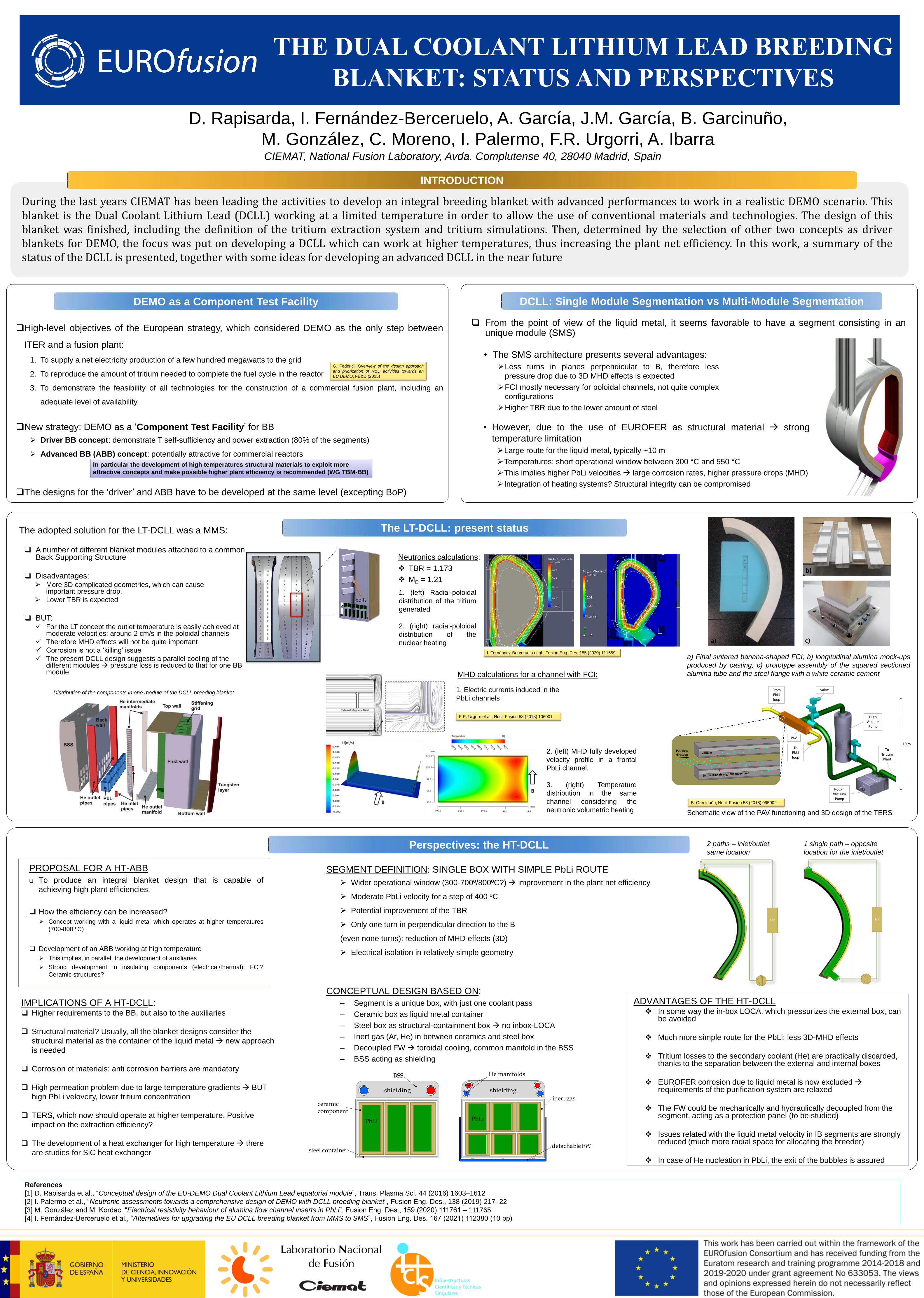
From the point of view of the liquid metal, it seems favorable to have a segment consisting in an unique module (SMS)
• The SMS architecture presents several advantages:
Less turns in planes perpendicular to B, therefore less
pressure drop due to 3D MHD effects is expected
FCI mostly necessary for poloidal channels, not quite complex
configurations
Higher TBR due to the lower amount of steel
• However, due to the use of EUROFER as structural material strong
temperature limitation
Large route for the liquid metal, typically ~10 m
Temperatures: short operational window between 300 °C and 550 °C
This implies higher PbLi velocities large corrosion rates, higher pressure drops (MHD)
Integration of heating systems? Structural integrity can be compromised
bolts
PROPOSAL FOR A HT-ABB
To produce an integral blanket design that is capable of
achieving high plant efficiencies.
How the efficiency can be increased?
Concept working with a liquid metal which operates at higher temperatures
(700-800 ºC)
Development of an ABB working at high temperature
This implies, in parallel, the development of auxiliaries
Strong development in insulating components (electrical/thermal): FCI?
Ceramic structures?
ADVANTAGES OF THE HT-DCLL In some way the in-box LOCA, which pressurizes the external box, can
be avoided
Much more simple route for the PbLi: less 3D-MHD effects
Tritium losses to the secondary coolant (He) are practically discarded, thanks to the separation between the external and internal boxes
EUROFER corrosion due to liquid metal is now excluded requirements of the purification system are relaxed
The FW could be mechanically and hydraulically decoupled from the segment, acting as a protection panel (to be studied)
Issues related with the liquid metal velocity in IB segments are strongly reduced (much more radial space for allocating the breeder)
In case of He nucleation in PbLi, the exit of the bubbles is assured
CONCEPTUAL DESIGN BASED ON:
– Segment is a unique box, with just one coolant pass
– Ceramic box as liquid metal container
– Steel box as structural-containment box no inbox-LOCA
– Inert gas (Ar, He) in between ceramics and steel box
– Decoupled FW toroidal cooling, common manifold in the BSS
– BSS acting as shielding
SEGMENT DEFINITION: SINGLE BOX WITH SIMPLE PbLi ROUTE
Wider operational window (300-700º/800ºC?) improvement in the plant net efficiency
Moderate PbLi velocity for a step of 400 ºC
Potential improvement of the TBR
Only one turn in perpendicular direction to the B
(even none turns): reduction of MHD effects (3D)
Electrical isolation in relatively simple geometry
HX HX
shielding shielding
PbLi PbLi
ceramiccomponent
steel container
BSS He manifolds
inert gas
detachable FW
DCLL: Single Module Segmentation vs Multi-Module Segmentation
The adopted solution for the LT-DCLL was a MMS:
A number of different blanket modules attached to a common Back Supporting Structure
Disadvantages: More 3D complicated geometries, which can cause
important pressure drop.
Lower TBR is expected
BUT: For the LT concept the outlet temperature is easily achieved at
moderate velocities: around 2 cm/s in the poloidal channels
Therefore MHD effects will not be quite important
Corrosion is not a ‘killing’ issue
The present DCLL design suggests a parallel cooling of the different modules pressure loss is reduced to that for one BB module
Distribution of the components in one module of the DCLL breeding blanket
1. (left) Radial-poloidal
distribution of the tritium
generated
2. (right) radial-poloidal
distribution of the
nuclear heating
1. Electric currents induced in the
PbLi channels
a)
b)
c)
a) Final sintered banana-shaped FCI; b) longitudinal alumina mock-ups
produced by casting; c) prototype assembly of the squared sectioned
alumina tube and the steel flange with a white ceramic cement
From PbLiloop
To PbLiloop
To Tritium Plant
High Vacuum Pump
Rough Vacuum
Pump
valve
PAV
10 m
Schematic view of the PAV functioning and 3D design of the TERS
IMPLICATIONS OF A HT-DCLL: Higher requirements to the BB, but also to the auxiliaries
Structural material? Usually, all the blanket designs consider the
structural material as the container of the liquid metal new approach
is needed
Corrosion of materials: anti corrosion barriers are mandatory
High permeation problem due to large temperature gradients BUT
high PbLi velovcity, lower tritium concentration
TERS, which now should operate at higher temperature. Positive
impact on the extraction efficiency?
The development of a heat exchanger for high temperature there
are studies for SiC heat exchanger
1 single path – opposite
location for the inlet/outlet
2 paths – inlet/outlet
same location
Neutronics calculations:
TBR = 1.173
ME = 1.21
MHD calculations for a channel with FCI:
2. (left) MHD fully developed
velocity profile in a frontal
PbLi channel.
3. (right) Temperature
distribution in the same
channel considering the
neutronic volumetric heating B. Garcinuño, Nucl. Fusion 58 (2018) 095002
I. Fernández-Berceruelo et al., Fusion Eng. Des. 155 (2020) 111559
F.R. Urgorri et al., Nucl. Fusion 58 (2018) 106001