Embed Size (px)
Citation preview
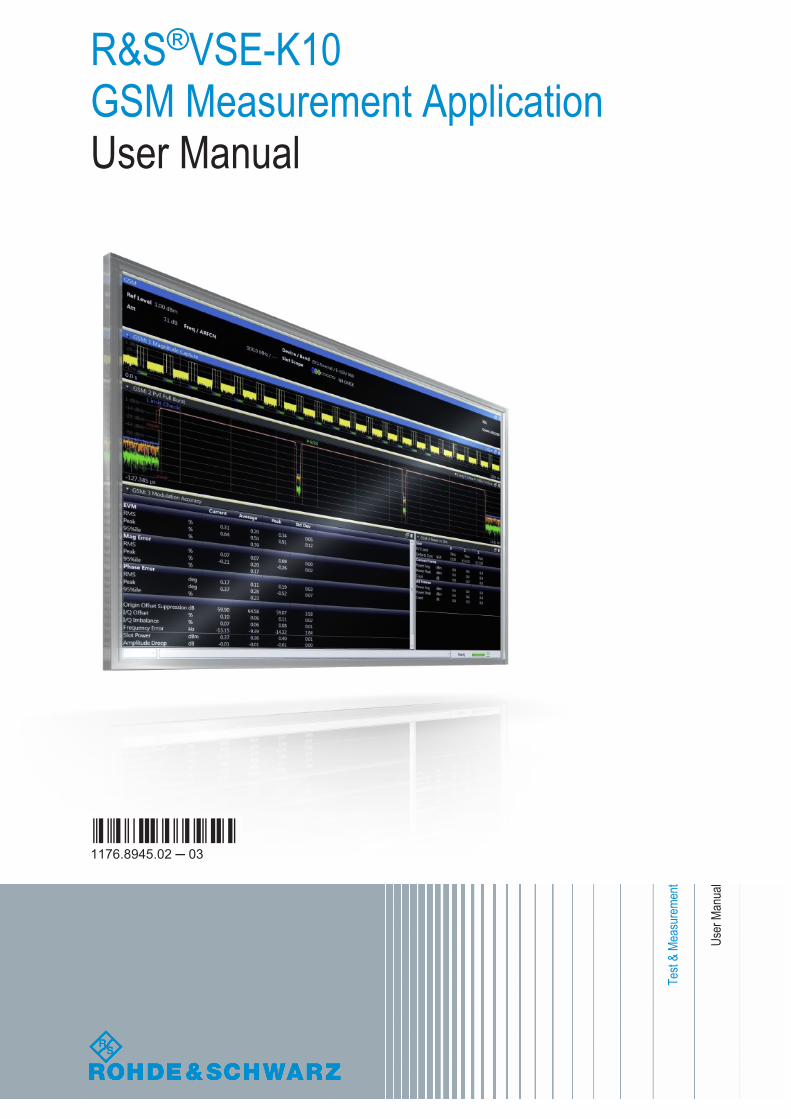
R&S®VSE-K10GSM Measurement ApplicationUser Manual
User
Man
ual
1176.8945.02 ─ 03(;Úç]2)
Test
& Me
asur
emen
t
This manual applies to the R&S®VSE base software (1320.7500.xx / 1320.7951.xx) version 1.30 and later.The following firmware options are described:● R&S VSE-K10 (1320.7574.02)
© 2017 Rohde & Schwarz GmbH & Co. KGMühldorfstr. 15, 81671 München, GermanyPhone: +49 89 41 29 - 0Fax: +49 89 41 29 12 164Email: [email protected]: www.rohde-schwarz.comSubject to change – Data without tolerance limits is not binding.R&S® is a registered trademark of Rohde & Schwarz GmbH & Co. KG.Trade names are trademarks of their owners.
The following abbreviations are used throughout this manual: R&S®VSE is abbreviated as R&S VSE.
ContentsR&S®VSE-K10
3User Manual 1176.8945.02 ─ 03
Contents1 Preface.................................................................................................... 5
1.1 About this Manual......................................................................................................... 5
1.2 Typographical Conventions.........................................................................................5
2 Welcome to the GSM Application.........................................................72.1 Starting the GSM Application...................................................................................... 7
2.2 Understanding the Display Information......................................................................8
3 About the Measurement...................................................................... 11
4 GSM I/Q Measurement Results...........................................................12
5 Basics on GSM Measurements...........................................................295.1 Relevant Digital Standards.........................................................................................29
5.2 Short introduction to GSM (GMSK, EDGE and EDGE Evolution)...........................29
5.3 Short Introduction to VAMOS.................................................................................... 33
5.4 AQPSK Modulation..................................................................................................... 34
5.5 Trigger settings........................................................................................................... 35
5.6 Defining the Scope of the Measurement...................................................................36
5.7 Overview of filters in the R&S VSE GSM application.............................................. 38
5.8 Dependency of Slot Parameters................................................................................ 42
5.9 Definition of the Symbol Period.................................................................................42
5.10 Synchronization.......................................................................................................... 46
5.11 Timeslot Alignment.....................................................................................................48
5.12 Delta to Sync Values...................................................................................................50
5.13 Limit Checks................................................................................................................51
5.14 Impact of the "Statistic Count".................................................................................. 53
6 Modulation Accuracy Measurement Configuration..........................546.1 Configuration Overview..............................................................................................54
6.2 Signal Description.......................................................................................................56
6.3 Input, Output and Frontend Settings.........................................................................65
6.4 Trigger Settings...........................................................................................................76
6.5 Data Acquisition..........................................................................................................80
6.6 Demodulation.............................................................................................................. 82
ContentsR&S®VSE-K10
4User Manual 1176.8945.02 ─ 03
6.7 Measurement Settings................................................................................................87
6.8 Adjusting Settings Automatically..............................................................................91
6.9 Result Configuration...................................................................................................92
7 How to Perform Measurements in the GSM Application................1037.1 How to Perform a Basic Measurement on GSM Signals....................................... 103
7.2 How to Determine Modulation Accuracy Parameters for GSM Signals...............104
7.3 How to Analyze the Power in GSM Signals............................................................ 105
7.4 How to Analyze the Spectrum of GSM Signals...................................................... 107
8 Optimizing and Troubleshooting the Measurement....................... 1108.1 Improving Performance............................................................................................110
8.2 Improving EVM Accuracy.........................................................................................110
8.3 Optimizing Limit Checks.......................................................................................... 111
8.4 Error Messages......................................................................................................... 112
9 Remote Commands to Perform GSM Measurements.....................1139.1 Introduction............................................................................................................... 113
9.2 Common Suffixes......................................................................................................118
9.3 Activating GSM Measurements............................................................................... 119
9.4 Restoring the Default Configuration (Preset).........................................................119
9.5 Configuring and Performing GSM I/Q Measurements........................................... 119
9.6 Analyzing GSM Measurements................................................................................169
9.7 Retrieving Results.....................................................................................................194
9.8 Status Reporting System......................................................................................... 234
9.9 Deprecated Commands............................................................................................ 239
9.10 Programming Examples........................................................................................... 247
Annex.................................................................................................. 258
A Annex: Reference...............................................................................258A.1 List of abbreviations................................................................................................. 258
A.2 Menu Reference........................................................................................................ 259
List of Commands..............................................................................268
Index....................................................................................................276
PrefaceR&S®VSE-K10
5User Manual 1176.8945.02 ─ 03
1 Preface
1.1 About this Manual
This R&S VSE GSM User Manual provides all the information specific to the applica-tion. All general software functions and settings common to all applications and oper-ating modes are described in the R&S VSE Base Software User Manual.
The main focus in this manual is on the measurement results and the tasks required toobtain them. The following topics are included:
● Welcome to the R&S VSE GSM applicationIntroduction to and getting familiar with the application
● Measurements and Result DisplaysDetails on supported measurements and their result types
● Measurement BasicsBackground information on basic terms and principles in the context of the mea-surement
● Configuration + AnalysisA concise description of all functions and settings available to configure measure-ments and analyze results with their corresponding remote control command
● How to Perform Measurements in the R&S VSE GSM applicationThe basic procedure to perform each measurement and step-by-step instructionsfor more complex tasks or alternative methods
● Optimizing and Troubleshooting the MeasurementHints and tips on how to handle errors and optimize the measurement configura-tion
● Remote Commands for GSM MeasurementsRemote commands required to configure and perform GSM measurements in aremote environment, sorted by tasks(Commands required to set up the environment or to perform common tasks in thesoftware are provided in the R&S VSE Base Software User Manual)Programming examples demonstrate the use of many commands and can usuallybe executed directly for test purposes
● List of remote commandsAlphabetical list of all remote commands described in the manual
● Index
1.2 Typographical Conventions
The following text markers are used throughout this documentation:
Typographical Conventions
PrefaceR&S®VSE-K10
6User Manual 1176.8945.02 ─ 03
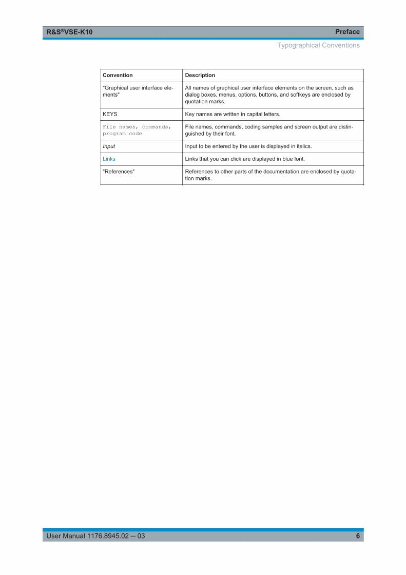
Convention Description
"Graphical user interface ele-ments"
All names of graphical user interface elements on the screen, such asdialog boxes, menus, options, buttons, and softkeys are enclosed byquotation marks.
KEYS Key names are written in capital letters.
File names, commands,program code
File names, commands, coding samples and screen output are distin-guished by their font.
Input Input to be entered by the user is displayed in italics.
Links Links that you can click are displayed in blue font.
"References" References to other parts of the documentation are enclosed by quota-tion marks.
Typographical Conventions
Welcome to the GSM ApplicationR&S®VSE-K10
7User Manual 1176.8945.02 ─ 03
2 Welcome to the GSM ApplicationThe R&S VSE-K10 is a firmware application that adds functionality to perform GSMmeasurements to the R&S VSE.
The R&S VSE GSM application features:
● Measurements on downlink or uplink signals according to the Third GenerationPartnership Project (3GPP) standards for GSM/EDGE, EDGE Evolution (EGPRS2)and Voice services over Adaptive Multi-user Channels on One Slot (VAMOS)
● Measurement in time, frequency or I/Q domains● Measurements of mobile devices (MS), single carrier and multicarrier base trans-
ceiver stations (BTS)● Measurement of signals with GMSK, AQPSK, QPSK, 8PSK, 16QAM and 32QAM
modulation, normal or higher symbol rate● Measurement of signals using different Tx filters (e.g. narrow and wide pulse)● Measurements for Power vs Time, Modulation Accuracy and Modulation and Tran-
sient Spectrum as required in the standard
This user manual contains a description of the functionality that the application pro-vides, including remote control operation.
Functions that are not discussed in this manual are the same as in the I/Q Analyzerapplication and are described in the R&S VSE Base Software User Manual. The latestversion is available for download at the product homepage (http://www2.rohde-schwarz.com/product/VSE.html).
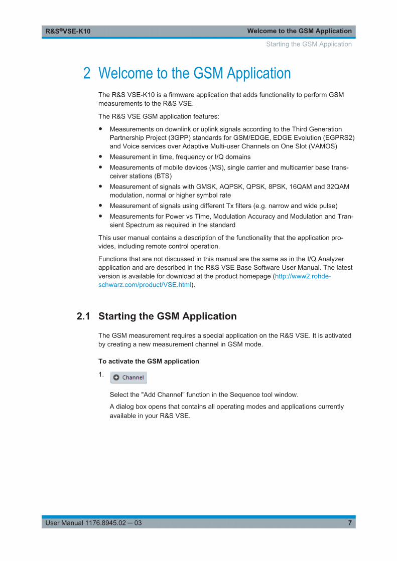
2.1 Starting the GSM Application
The GSM measurement requires a special application on the R&S VSE. It is activatedby creating a new measurement channel in GSM mode.
To activate the GSM application
1.
Select the "Add Channel" function in the Sequence tool window.
A dialog box opens that contains all operating modes and applications currentlyavailable in your R&S VSE.
Starting the GSM Application
Welcome to the GSM ApplicationR&S®VSE-K10
8User Manual 1176.8945.02 ─ 03
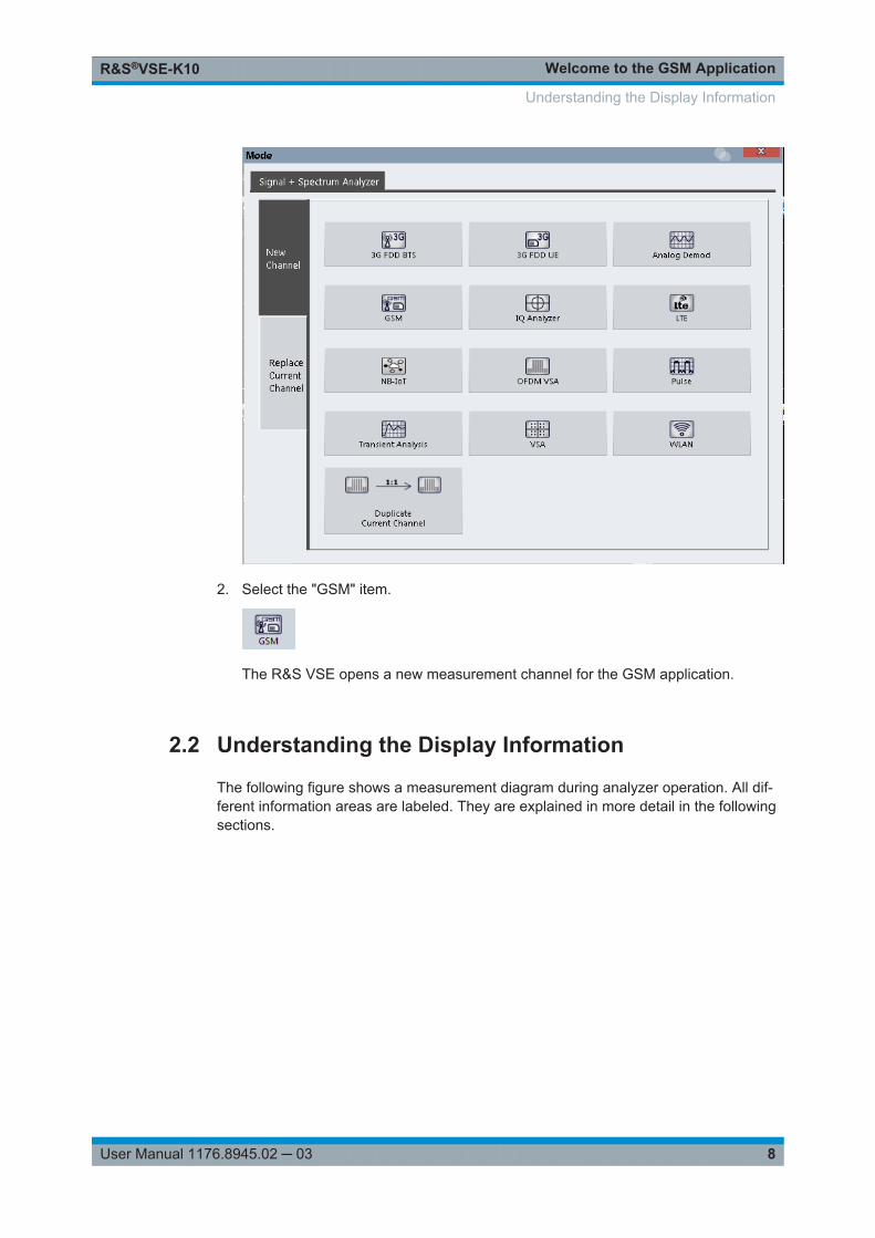
2. Select the "GSM" item.
The R&S VSE opens a new measurement channel for the GSM application.
2.2 Understanding the Display Information
The following figure shows a measurement diagram during analyzer operation. All dif-ferent information areas are labeled. They are explained in more detail in the followingsections.
Understanding the Display Information
Welcome to the GSM ApplicationR&S®VSE-K10
9User Manual 1176.8945.02 ─ 03
2
3
45
1
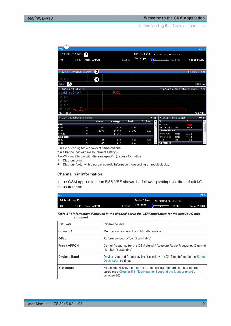
1 = Color coding for windows of same channel2 = Channel bar with measurement settings3 = Window title bar with diagram-specific (trace) information4 = Diagram area5 = Diagram footer with diagram-specific information, depending on result display
Channel bar information
In the GSM application, the R&S VSE shows the following settings for the default I/Qmeasurement:
Table 2-1: Information displayed in the channel bar in the GSM application for the default I/Q mea-surement
Ref Level Reference level
(m.+el.) Att Mechanical and electronic RF attenuation
Offset Reference level offset (if available)
Freq / ARFCN Center frequency for the GSM signal / Absolute Radio Frequency ChannelNumber (if available)
Device / Band Device type and frequency band used by the DUT as defined in the SignalDescription settings
Slot Scope Minimized visualization of the frame configuration and slots to be mea-sured (see Chapter 5.6, "Defining the Scope of the Measurement",on page 36)
Understanding the Display Information
Welcome to the GSM ApplicationR&S®VSE-K10
10User Manual 1176.8945.02 ─ 03
Count Number of frames already evaluated / Total number of frames required forstatistical evaluation (Statistic Count)
(For Statistic Count > 1)
TRG Trigger source (if not "Free Run") and used trigger bandwidth (for IF, RF,IP power triggers) or trigger offset (for external triggers)
In addition, the channel bar also displays information on instrument settings that affectthe measurement results even though this is not immediately apparent from the displayof the measured values. This information is displayed only when applicable for the cur-rent application. For details see the R&S VSE Base Software User Manual.
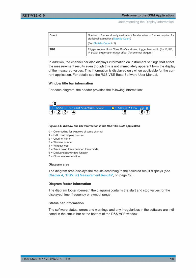
Window title bar information
For each diagram, the header provides the following information:
1 3 5 6 7
0
2 4
Figure 2-1: Window title bar information in the R&S VSE GSM application
0 = Color coding for windows of same channel1 = Edit result display function2 = Channel name3 = Window number4 = Window type5 = Trace color, trace number, trace mode6 = Dock/undock window function7 = Close window function
Diagram area
The diagram area displays the results according to the selected result displays (seeChapter 4, "GSM I/Q Measurement Results", on page 12).
Diagram footer information
The diagram footer (beneath the diagram) contains the start and stop values for thedisplayed time, frequency or symbol range.
Status bar information
The software status, errors and warnings and any irregularities in the software are indi-cated in the status bar at the bottom of the R&S VSE window.
Understanding the Display Information
About the MeasurementR&S®VSE-K10
11User Manual 1176.8945.02 ─ 03
3 About the MeasurementA basic GSM measurement in the R&S VSE GSM application includes a power vs timeand a spectrum measurement, as well as modulation accuracy (e.g. EVM, phase error)for a GSM signal as defined by the relevant 3GPP standards. The I/Q data from theGSM signal applied to the RF input of the R&S VSE is captured for a specified mea-surement time. This data is demodulated and synchronized with a reference signal toidentify the individual frames and slots. The slots of interest are then analyzed in orderto display the spectral and power results either graphically or numerically, and to calcu-late the modulation parameters.
The standard distinguishes between single-slot and multi-slot measurements. Single-slot measurements analyze one slot - referred to as the "Slot to measure" - within theGSM frame (which consists of 8 slots in total). Modulation-specific parameters such asthe phase error, EVM, or spectrum due to modulation are determined on a per-slotbasis. Multi-slot measurements, on the other hand, analyze a slot scope of up to 8 con-secutive slots, each of which has different burst modulation characteristics. Power vstime limit checks and the transient spectrum measurements, for example, are deter-mined for multiple slots.
Statistical evaluation of several measurements is also possible. Finally, the GSM mea-surement results can be exported to other applications.
GSM I/Q Measurement ResultsR&S®VSE-K10
12User Manual 1176.8945.02 ─ 03
4 GSM I/Q Measurement ResultsResult display windows
For each measurement, a separate measurement channel is activated. Each measure-ment channel can provide multiple result displays, which are displayed in individualwindows. The measurement windows can be rearranged and configured in theR&S VSE to meet your requirements. All windows that belong to the same measure-ment (including the channel bar) are indicated by a colored line at the top of the win-dow title bar.
► To add further result displays for the GSM channel, select the "Add Window"icon from the toolbar, or select the "Window > New Window" menu item.
For details on working with channels and windows see the "Operating Basics"chapter in the R&S VSE Base Software User Manual.
By default, the GSM measurement results for I/Q measurements are displayed in thefollowing windows:
● Magnitude Capture● PvT Full Burst● Modulation Accuracy● Power vs Slot
The following evaluation methods are available for GSM I/Q measurements:
Constellation................................................................................................................. 12EVM.............................................................................................................................. 13Magnitude Capture........................................................................................................13Magnitude Error............................................................................................................ 14Marker Table ................................................................................................................ 15Modulation Accuracy.....................................................................................................15Modulation Spectrum Graph......................................................................................... 17Modulation Spectrum Table.......................................................................................... 18Phase Error................................................................................................................... 20Power vs Slot................................................................................................................ 21PvT Full Burst................................................................................................................22Transient Spectrum Graph............................................................................................24Transient Spectrum Table.............................................................................................25Trigger to Sync Graph...................................................................................................26Trigger to Sync Table....................................................................................................28
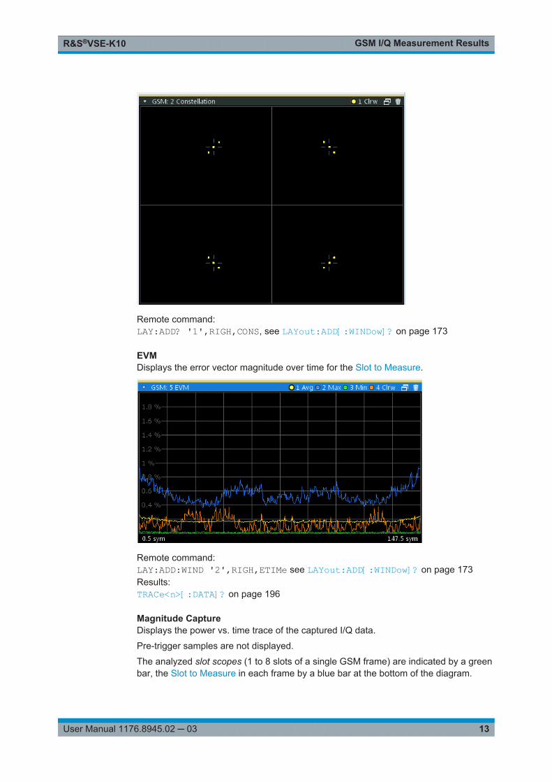
ConstellationThe complex source signal is displayed as an X/Y diagram. The application analyzesthe specified slot over the specified number of bursts.
GSM I/Q Measurement ResultsR&S®VSE-K10
13User Manual 1176.8945.02 ─ 03
Remote command: LAY:ADD? '1',RIGH,CONS, see LAYout:ADD[:WINDow]? on page 173
EVMDisplays the error vector magnitude over time for the Slot to Measure.
Remote command: LAY:ADD:WIND '2',RIGH,ETIMe see LAYout:ADD[:WINDow]? on page 173Results:TRACe<n>[:DATA]? on page 196
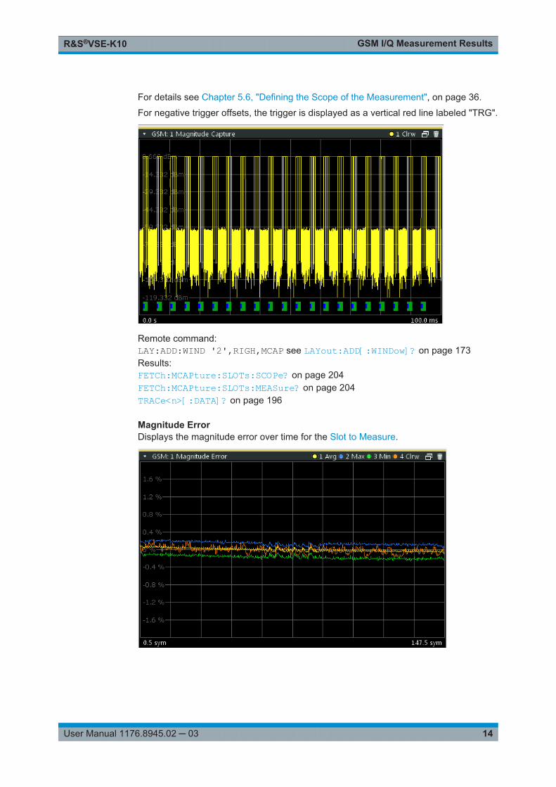
Magnitude CaptureDisplays the power vs. time trace of the captured I/Q data.
Pre-trigger samples are not displayed.
The analyzed slot scopes (1 to 8 slots of a single GSM frame) are indicated by a greenbar, the Slot to Measure in each frame by a blue bar at the bottom of the diagram.
GSM I/Q Measurement ResultsR&S®VSE-K10
14User Manual 1176.8945.02 ─ 03
For details see Chapter 5.6, "Defining the Scope of the Measurement", on page 36.
For negative trigger offsets, the trigger is displayed as a vertical red line labeled "TRG".
Remote command: LAY:ADD:WIND '2',RIGH,MCAP see LAYout:ADD[:WINDow]? on page 173Results:FETCh:MCAPture:SLOTs:SCOPe? on page 204FETCh:MCAPture:SLOTs:MEASure? on page 204TRACe<n>[:DATA]? on page 196
Magnitude ErrorDisplays the magnitude error over time for the Slot to Measure.

GSM I/Q Measurement ResultsR&S®VSE-K10
15User Manual 1176.8945.02 ─ 03
Remote command: LAY:ADD:WIND '2',RIGH,MERR see LAYout:ADD[:WINDow]? on page 173Results:TRACe<n>[:DATA]? on page 196
Marker TableDisplays a table with the current marker values for the active markers.
This table is displayed automatically if configured accordingly (see " Marker Table Dis-play " on page 99).
Remote command: LAY:ADD? '1',RIGH, MTAB, see LAYout:ADD[:WINDow]? on page 173Results:CALCulate<n>:MARKer<m>:X on page 233CALCulate<n>:MARKer<m>:Y? on page 234
Modulation AccuracyDisplays the numeric values of the fundamental modulation characteristics of the signalto be analyzed in the vector (I/Q) domain: error vector magnitude (EVM), magnitudeand phase error, IQ imbalance, etc.
The following modulation parameters are determined:
GSM I/Q Measurement ResultsR&S®VSE-K10
16User Manual 1176.8945.02 ─ 03
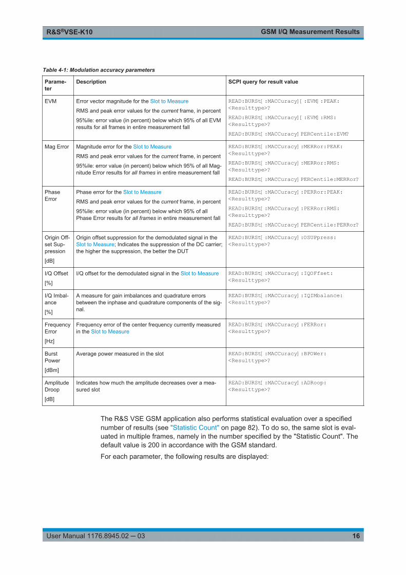
Table 4-1: Modulation accuracy parameters
Parame-ter
Description SCPI query for result value
EVM Error vector magnitude for the Slot to Measure
RMS and peak error values for the current frame, in percent
95%ile: error value (in percent) below which 95% of all EVMresults for all frames in entire measurement fall
READ:BURSt[:MACCuracy][:EVM]:PEAK:<Resulttype>?READ:BURSt[:MACCuracy][:EVM]:RMS:<Resulttype>?READ:BURSt[:MACCuracy]PERCentile:EVM?
Mag Error Magnitude error for the Slot to Measure
RMS and peak error values for the current frame, in percent
95%ile: error value (in percent) below which 95% of all Mag-nitude Error results for all frames in entire measurement fall
READ:BURSt[:MACCuracy]:MERRor:PEAK:<Resulttype>?READ:BURSt[:MACCuracy]:MERRor:RMS:<Resulttype>?READ:BURSt[:MACCuracy]PERCentile:MERRor?
PhaseError
Phase error for the Slot to Measure
RMS and peak error values for the current frame, in percent
95%ile: error value (in percent) below which 95% of allPhase Error results for all frames in entire measurement fall
READ:BURSt[:MACCuracy]:PERRor:PEAK:<Resulttype>?READ:BURSt[:MACCuracy]:PERRor:RMS:<Resulttype>?READ:BURSt[:MACCuracy]PERCentile:PERRor?
Origin Off-set Sup-pression
[dB]
Origin offset suppression for the demodulated signal in theSlot to Measure; Indicates the suppression of the DC carrier;the higher the suppression, the better the DUT
READ:BURSt[:MACCuracy]:OSUPpress:<Resulttype>?
I/Q Offset
[%]
I/Q offset for the demodulated signal in the Slot to Measure READ:BURSt[:MACCuracy]:IQOFfset:<Resulttype>?
I/Q Imbal-ance
[%]
A measure for gain imbalances and quadrature errorsbetween the inphase and quadrature components of the sig-nal.
READ:BURSt[:MACCuracy]:IQIMbalance:<Resulttype>?
FrequencyError
[Hz]
Frequency error of the center frequency currently measuredin the Slot to Measure
READ:BURSt[:MACCuracy]:FERRor:<Resulttype>?
BurstPower
[dBm]
Average power measured in the slot READ:BURSt[:MACCuracy]:BPOWer:<Resulttype>?
AmplitudeDroop
[dB]
Indicates how much the amplitude decreases over a mea-sured slot
READ:BURSt[:MACCuracy]:ADRoop:<Resulttype>?
The R&S VSE GSM application also performs statistical evaluation over a specifiednumber of results (see "Statistic Count" on page 82). To do so, the same slot is eval-uated in multiple frames, namely in the number specified by the "Statistic Count". Thedefault value is 200 in accordance with the GSM standard.
For each parameter, the following results are displayed:
GSM I/Q Measurement ResultsR&S®VSE-K10
17User Manual 1176.8945.02 ─ 03
Table 4-2: Calculated summary results
Resulttype
Description SCPI query for result value
Current Value for currently measured frame only READ:BURSt[:MACCuracy]:<Parameter>:CURRent?
Average Linear average value of "Current" results from the specifiednumber of frames
Exception: The average of the "Origin Offset Suppression"is the linear average of the power ratio, converted to dBmsubsequently
READ:BURSt[:MACCuracy]:<Parameter>:AVERage?
Peak Maximum value of "Current" results from specified number offrames
Exception: The peak of the "Origin Offset Suppression" isthe minimum value, as this represents the worst case, whichneeds to be detected
READ:BURSt[:MACCuracy]:<Parameter>:MAXimum?
Std Dev Standard deviation of "Current" results for specified numberof frames
READ:BURSt[:MACCuracy]:<Parameter>:SDEViation?
Remote command: LAY:ADD:WIND '2',RIGH,MACC see LAYout:ADD[:WINDow]? on page 173Results:READ:BURSt[:MACCuracy]:ALL on page 208Chapter 9.7.4, "Modulation Accuracy Results", on page 205
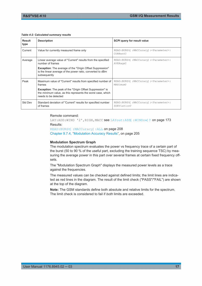
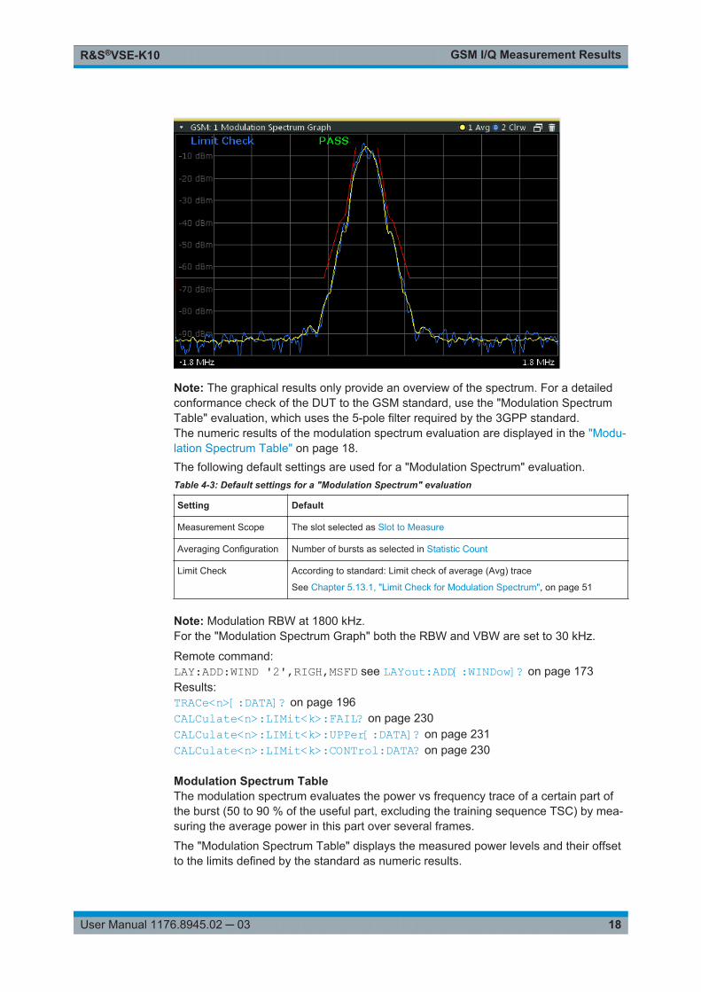
Modulation Spectrum GraphThe modulation spectrum evaluates the power vs frequency trace of a certain part ofthe burst (50 to 90 % of the useful part, excluding the training sequence TSC) by mea-suring the average power in this part over several frames at certain fixed frequency off-sets.
The "Modulation Spectrum Graph" displays the measured power levels as a traceagainst the frequencies.
The measured values can be checked against defined limits; the limit lines are indica-ted as red lines in the diagram. The result of the limit check ("PASS"/"FAIL") are shownat the top of the diagram.
Note: The GSM standards define both absolute and relative limits for the spectrum.The limit check is considered to fail if both limits are exceeded.
GSM I/Q Measurement ResultsR&S®VSE-K10
18User Manual 1176.8945.02 ─ 03
Note: The graphical results only provide an overview of the spectrum. For a detailedconformance check of the DUT to the GSM standard, use the "Modulation SpectrumTable" evaluation, which uses the 5-pole filter required by the 3GPP standard.The numeric results of the modulation spectrum evaluation are displayed in the "Modu-lation Spectrum Table" on page 18.The following default settings are used for a "Modulation Spectrum" evaluation.Table 4-3: Default settings for a "Modulation Spectrum" evaluation
Setting Default
Measurement Scope The slot selected as Slot to Measure
Averaging Configuration Number of bursts as selected in Statistic Count
Limit Check According to standard: Limit check of average (Avg) trace
See Chapter 5.13.1, "Limit Check for Modulation Spectrum", on page 51
Note: Modulation RBW at 1800 kHz.For the "Modulation Spectrum Graph" both the RBW and VBW are set to 30 kHz.
Remote command: LAY:ADD:WIND '2',RIGH,MSFD see LAYout:ADD[:WINDow]? on page 173Results:TRACe<n>[:DATA]? on page 196CALCulate<n>:LIMit<k>:FAIL? on page 230CALCulate<n>:LIMit<k>:UPPer[:DATA]? on page 231CALCulate<n>:LIMit<k>:CONTrol:DATA? on page 230
Modulation Spectrum TableThe modulation spectrum evaluates the power vs frequency trace of a certain part ofthe burst (50 to 90 % of the useful part, excluding the training sequence TSC) by mea-suring the average power in this part over several frames.
The "Modulation Spectrum Table" displays the measured power levels and their offsetto the limits defined by the standard as numeric results.
GSM I/Q Measurement ResultsR&S®VSE-K10
19User Manual 1176.8945.02 ─ 03
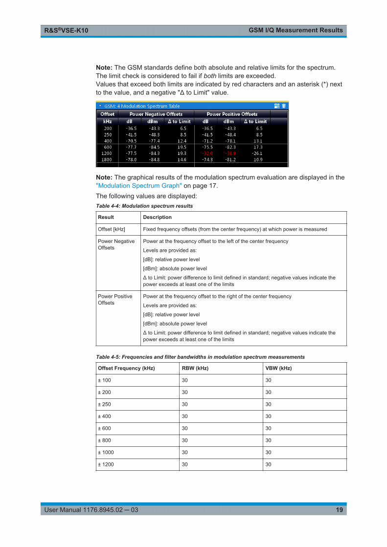
Note: The GSM standards define both absolute and relative limits for the spectrum.The limit check is considered to fail if both limits are exceeded.Values that exceed both limits are indicated by red characters and an asterisk (*) nextto the value, and a negative "Δ to Limit" value.
Note: The graphical results of the modulation spectrum evaluation are displayed in the"Modulation Spectrum Graph" on page 17.The following values are displayed:Table 4-4: Modulation spectrum results
Result Description
Offset [kHz] Fixed frequency offsets (from the center frequency) at which power is measured
Power NegativeOffsets
Power at the frequency offset to the left of the center frequency
Levels are provided as:
[dB]: relative power level
[dBm]: absolute power level
Δ to Limit: power difference to limit defined in standard; negative values indicate thepower exceeds at least one of the limits
Power PositiveOffsets
Power at the frequency offset to the right of the center frequency
Levels are provided as:
[dB]: relative power level
[dBm]: absolute power level
Δ to Limit: power difference to limit defined in standard; negative values indicate thepower exceeds at least one of the limits
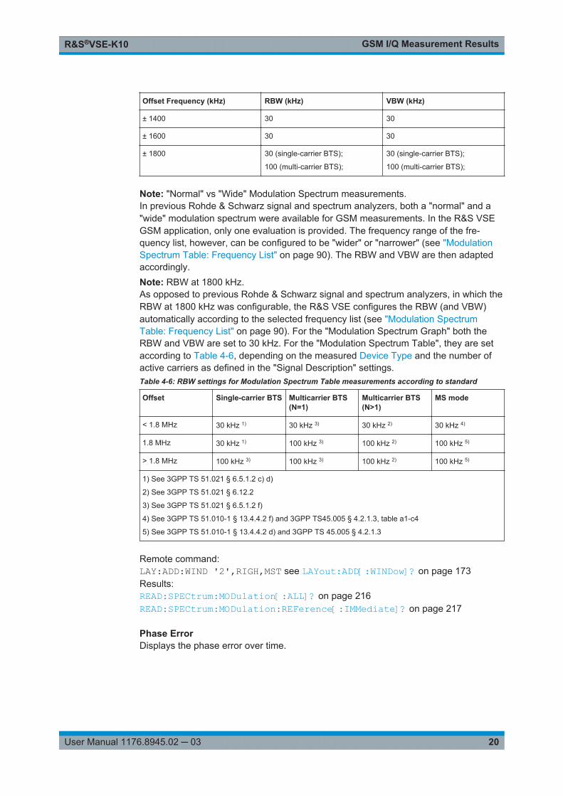
Table 4-5: Frequencies and filter bandwidths in modulation spectrum measurements
Offset Frequency (kHz) RBW (kHz) VBW (kHz)
± 100 30 30
± 200 30 30
± 250 30 30
± 400 30 30
± 600 30 30
± 800 30 30
± 1000 30 30
± 1200 30 30
GSM I/Q Measurement ResultsR&S®VSE-K10
20User Manual 1176.8945.02 ─ 03
Offset Frequency (kHz) RBW (kHz) VBW (kHz)
± 1400 30 30
± 1600 30 30
± 1800 30 (single-carrier BTS);
100 (multi-carrier BTS);
30 (single-carrier BTS);
100 (multi-carrier BTS);
Note: "Normal" vs "Wide" Modulation Spectrum measurements.In previous Rohde & Schwarz signal and spectrum analyzers, both a "normal" and a"wide" modulation spectrum were available for GSM measurements. In the R&S VSEGSM application, only one evaluation is provided. The frequency range of the fre-quency list, however, can be configured to be "wider" or "narrower" (see "ModulationSpectrum Table: Frequency List" on page 90). The RBW and VBW are then adaptedaccordingly.Note: RBW at 1800 kHz.As opposed to previous Rohde & Schwarz signal and spectrum analyzers, in which theRBW at 1800 kHz was configurable, the R&S VSE configures the RBW (and VBW)automatically according to the selected frequency list (see "Modulation SpectrumTable: Frequency List" on page 90). For the "Modulation Spectrum Graph" both theRBW and VBW are set to 30 kHz. For the "Modulation Spectrum Table", they are setaccording to Table 4-6, depending on the measured Device Type and the number ofactive carriers as defined in the "Signal Description" settings.Table 4-6: RBW settings for Modulation Spectrum Table measurements according to standard
Offset Single-carrier BTS Multicarrier BTS(N=1)
Multicarrier BTS(N>1)
MS mode
< 1.8 MHz 30 kHz 1) 30 kHz 3) 30 kHz 2) 30 kHz 4)
1.8 MHz 30 kHz 1) 100 kHz 3) 100 kHz 2) 100 kHz 5)
> 1.8 MHz 100 kHz 3) 100 kHz 3) 100 kHz 2) 100 kHz 5)
1) See 3GPP TS 51.021 § 6.5.1.2 c) d)
2) See 3GPP TS 51.021 § 6.12.2
3) See 3GPP TS 51.021 § 6.5.1.2 f)
4) See 3GPP TS 51.010-1 § 13.4.4.2 f) and 3GPP TS45.005 § 4.2.1.3, table a1-c4
5) See 3GPP TS 51.010-1 § 13.4.4.2 d) and 3GPP TS 45.005 § 4.2.1.3
Remote command: LAY:ADD:WIND '2',RIGH,MST see LAYout:ADD[:WINDow]? on page 173Results:READ:SPECtrum:MODulation[:ALL]? on page 216READ:SPECtrum:MODulation:REFerence[:IMMediate]? on page 217
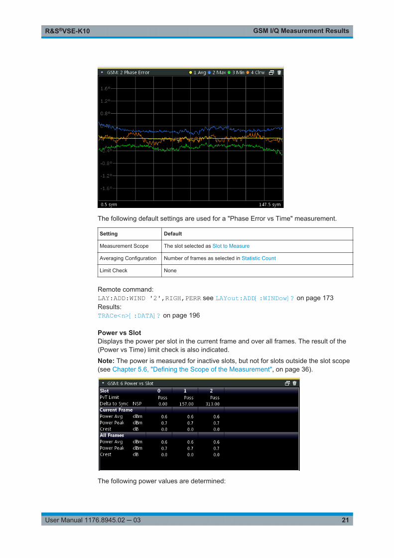
Phase ErrorDisplays the phase error over time.
GSM I/Q Measurement ResultsR&S®VSE-K10
21User Manual 1176.8945.02 ─ 03
The following default settings are used for a "Phase Error vs Time" measurement.
Setting Default
Measurement Scope The slot selected as Slot to Measure
Averaging Configuration Number of frames as selected in Statistic Count
Limit Check None
Remote command: LAY:ADD:WIND '2',RIGH,PERR see LAYout:ADD[:WINDow]? on page 173Results:TRACe<n>[:DATA]? on page 196
Power vs SlotDisplays the power per slot in the current frame and over all frames. The result of the(Power vs Time) limit check is also indicated.
Note: The power is measured for inactive slots, but not for slots outside the slot scope(see Chapter 5.6, "Defining the Scope of the Measurement", on page 36).
The following power values are determined:
GSM I/Q Measurement ResultsR&S®VSE-K10
22User Manual 1176.8945.02 ─ 03
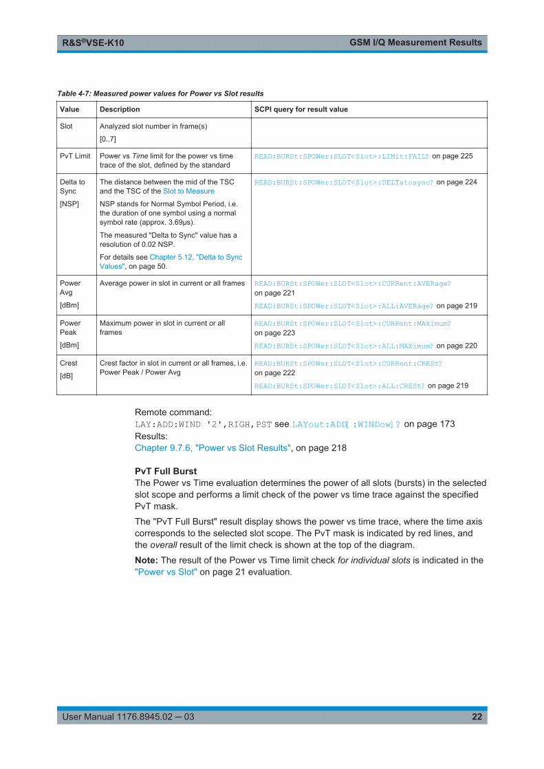
Table 4-7: Measured power values for Power vs Slot results
Value Description SCPI query for result value
Slot Analyzed slot number in frame(s)
[0..7]
PvT Limit Power vs Time limit for the power vs timetrace of the slot, defined by the standard
READ:BURSt:SPOWer:SLOT<Slot>:LIMit:FAIL? on page 225
Delta toSync
[NSP]
The distance between the mid of the TSCand the TSC of the Slot to Measure
NSP stands for Normal Symbol Period, i.e.the duration of one symbol using a normalsymbol rate (approx. 3.69μs).
The measured "Delta to Sync" value has aresolution of 0.02 NSP.
For details see Chapter 5.12, "Delta to SyncValues", on page 50.
READ:BURSt:SPOWer:SLOT<Slot>:DELTatosync? on page 224
PowerAvg
[dBm]
Average power in slot in current or all frames READ:BURSt:SPOWer:SLOT<Slot>:CURRent:AVERage?on page 221
READ:BURSt:SPOWer:SLOT<Slot>:ALL:AVERage? on page 219
PowerPeak
[dBm]
Maximum power in slot in current or allframes
READ:BURSt:SPOWer:SLOT<Slot>:CURRent:MAXimum?on page 223
READ:BURSt:SPOWer:SLOT<Slot>:ALL:MAXimum? on page 220
Crest
[dB]
Crest factor in slot in current or all frames, i.e.Power Peak / Power Avg
READ:BURSt:SPOWer:SLOT<Slot>:CURRent:CRESt?on page 222
READ:BURSt:SPOWer:SLOT<Slot>:ALL:CRESt? on page 219
Remote command: LAY:ADD:WIND '2',RIGH,PST see LAYout:ADD[:WINDow]? on page 173Results:Chapter 9.7.6, "Power vs Slot Results", on page 218
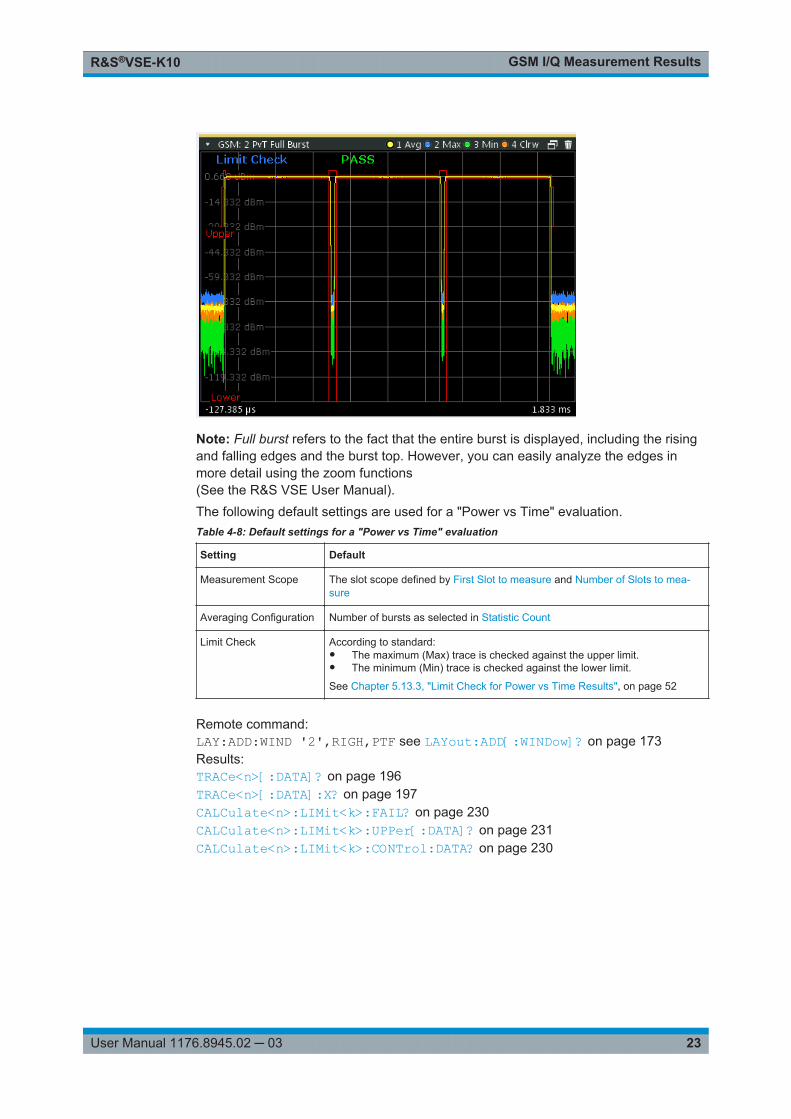
PvT Full BurstThe Power vs Time evaluation determines the power of all slots (bursts) in the selectedslot scope and performs a limit check of the power vs time trace against the specifiedPvT mask.
The "PvT Full Burst" result display shows the power vs time trace, where the time axiscorresponds to the selected slot scope. The PvT mask is indicated by red lines, andthe overall result of the limit check is shown at the top of the diagram.
Note: The result of the Power vs Time limit check for individual slots is indicated in the"Power vs Slot" on page 21 evaluation.
GSM I/Q Measurement ResultsR&S®VSE-K10
23User Manual 1176.8945.02 ─ 03
Note: Full burst refers to the fact that the entire burst is displayed, including the risingand falling edges and the burst top. However, you can easily analyze the edges inmore detail using the zoom functions(See the R&S VSE User Manual).The following default settings are used for a "Power vs Time" evaluation.Table 4-8: Default settings for a "Power vs Time" evaluation
Setting Default
Measurement Scope The slot scope defined by First Slot to measure and Number of Slots to mea-sure
Averaging Configuration Number of bursts as selected in Statistic Count
Limit Check According to standard:● The maximum (Max) trace is checked against the upper limit.● The minimum (Min) trace is checked against the lower limit.
See Chapter 5.13.3, "Limit Check for Power vs Time Results", on page 52
Remote command: LAY:ADD:WIND '2',RIGH,PTF see LAYout:ADD[:WINDow]? on page 173Results:TRACe<n>[:DATA]? on page 196TRACe<n>[:DATA]:X? on page 197CALCulate<n>:LIMit<k>:FAIL? on page 230CALCulate<n>:LIMit<k>:UPPer[:DATA]? on page 231CALCulate<n>:LIMit<k>:CONTrol:DATA? on page 230
GSM I/Q Measurement ResultsR&S®VSE-K10
24User Manual 1176.8945.02 ─ 03
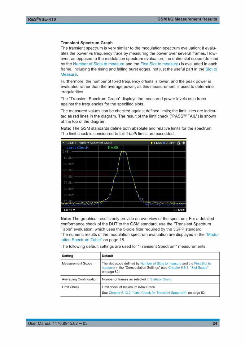
Transient Spectrum GraphThe transient spectrum is very similar to the modulation spectrum evaluation; it evalu-ates the power vs frequency trace by measuring the power over several frames. How-ever, as opposed to the modulation spectrum evaluation, the entire slot scope (definedby the Number of Slots to measure and the First Slot to measure) is evaluated in eachframe, including the rising and falling burst edges, not just the useful part in the Slot toMeasure.
Furthermore, the number of fixed frequency offsets is lower, and the peak power isevaluated rather than the average power, as this measurement is used to determineirregularities.
The "Transient Spectrum Graph" displays the measured power levels as a traceagainst the frequencies for the specified slots.
The measured values can be checked against defined limits; the limit lines are indica-ted as red lines in the diagram. The result of the limit check ("PASS"/"FAIL") is shownat the top of the diagram.
Note: The GSM standards define both absolute and relative limits for the spectrum.The limit check is considered to fail if both limits are exceeded.
Note: The graphical results only provide an overview of the spectrum. For a detailedconformance check of the DUT to the GSM standard, use the "Transient SpectrumTable" evaluation, which uses the 5-pole filter required by the 3GPP standard.The numeric results of the modulation spectrum evaluation are displayed in the "Modu-lation Spectrum Table" on page 18.The following default settings are used for "Transient Spectrum" measurements.
Setting Default
Measurement Scope The slot scope defined by Number of Slots to measure and the First Slot tomeasure in the "Demodulation Settings" (see Chapter 6.6.1, "Slot Scope",on page 82).
Averaging Configuration Number of frames as selected in Statistic Count
Limit Check Limit check of maximum (Max) trace
See Chapter 5.13.2, "Limit Check for Transient Spectrum", on page 52
GSM I/Q Measurement ResultsR&S®VSE-K10
25User Manual 1176.8945.02 ─ 03
Remote command: LAY:ADD:WIND '2',RIGH,TSFD see LAYout:ADD[:WINDow]? on page 173Results:TRACe<n>[:DATA]? on page 196CALCulate<n>:LIMit<k>:FAIL? on page 230
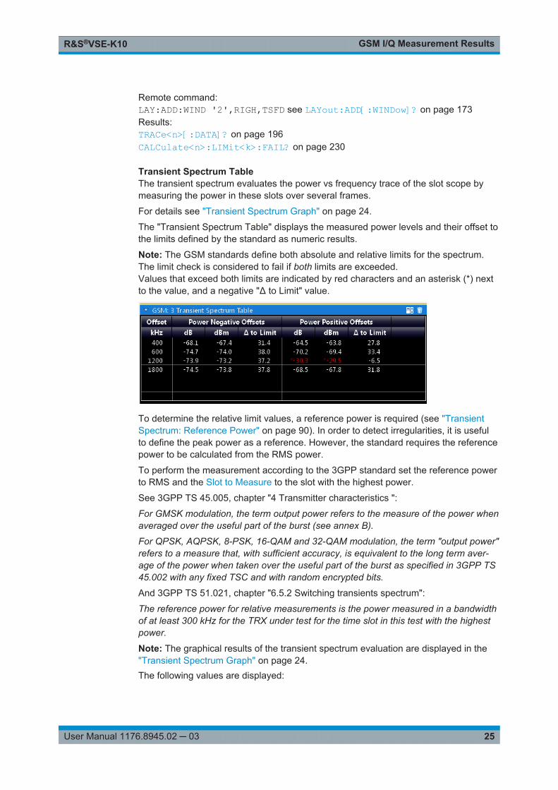
Transient Spectrum TableThe transient spectrum evaluates the power vs frequency trace of the slot scope bymeasuring the power in these slots over several frames.
For details see "Transient Spectrum Graph" on page 24.
The "Transient Spectrum Table" displays the measured power levels and their offset tothe limits defined by the standard as numeric results.
Note: The GSM standards define both absolute and relative limits for the spectrum.The limit check is considered to fail if both limits are exceeded.Values that exceed both limits are indicated by red characters and an asterisk (*) nextto the value, and a negative "Δ to Limit" value.
To determine the relative limit values, a reference power is required (see "TransientSpectrum: Reference Power" on page 90). In order to detect irregularities, it is usefulto define the peak power as a reference. However, the standard requires the referencepower to be calculated from the RMS power.
To perform the measurement according to the 3GPP standard set the reference powerto RMS and the Slot to Measure to the slot with the highest power.
See 3GPP TS 45.005, chapter "4 Transmitter characteristics ":
For GMSK modulation, the term output power refers to the measure of the power whenaveraged over the useful part of the burst (see annex B).
For QPSK, AQPSK, 8-PSK, 16-QAM and 32-QAM modulation, the term "output power"refers to a measure that, with sufficient accuracy, is equivalent to the long term aver-age of the power when taken over the useful part of the burst as specified in 3GPP TS45.002 with any fixed TSC and with random encrypted bits.
And 3GPP TS 51.021, chapter "6.5.2 Switching transients spectrum":
The reference power for relative measurements is the power measured in a bandwidthof at least 300 kHz for the TRX under test for the time slot in this test with the highestpower.
Note: The graphical results of the transient spectrum evaluation are displayed in the"Transient Spectrum Graph" on page 24.The following values are displayed:
GSM I/Q Measurement ResultsR&S®VSE-K10
26User Manual 1176.8945.02 ─ 03
Table 4-9: Transient spectrum results
Result Description
Offset
[kHz]
Fixed frequency offsets (from the center frequency) at which power is measured
Power NegativeOffsets
Power at the frequency offset to the left of the center frequency
Levels are provided as:
[dB]: relative power level
[dBm]: absolute power level
Δ to Limit: power difference to limit defined in standard; negative values indicate thepower exceeds at least one of the limits
Power PositiveOffsets
Power at the frequency offset to the right of the center frequency
Levels are provided as:
[dB]: relative power level
[dBm]: absolute power level
Δ to Limit: power difference to limit defined in standard; negative values indicate thepower exceeds at least one of the limits
Remote command: LAY:ADD:WIND '2',RIGH,TST see LAYout:ADD[:WINDow]? on page 173Results:READ:SPECtrum:SWITching[:ALL]? on page 226READ:SPECtrum:SWITching:REFerence[:IMMediate] on page 227
Trigger to Sync GraphThe Trigger to Sync measurement determines the time between an external triggerevent and the start of the first symbol of the TSC. The start of the first symbol of theTSC corresponds to the time 0 of the symbol period (see Chapter 5.9, "Definition of theSymbol Period", on page 42).
Only one result per data capture is provided. Therefore, it is useful to perform severaldata captures and average the results to obtain an accurate value (see "StatisticCount" on page 82).
Both graphical and numeric (table) results are available. While the graphical results aremainly used to determine the required measurement settings, the numeric results pro-vide the actual trigger to sync value, including statistical evaluation (see "Trigger toSync Table" on page 28).
GSM I/Q Measurement ResultsR&S®VSE-K10
27User Manual 1176.8945.02 ─ 03
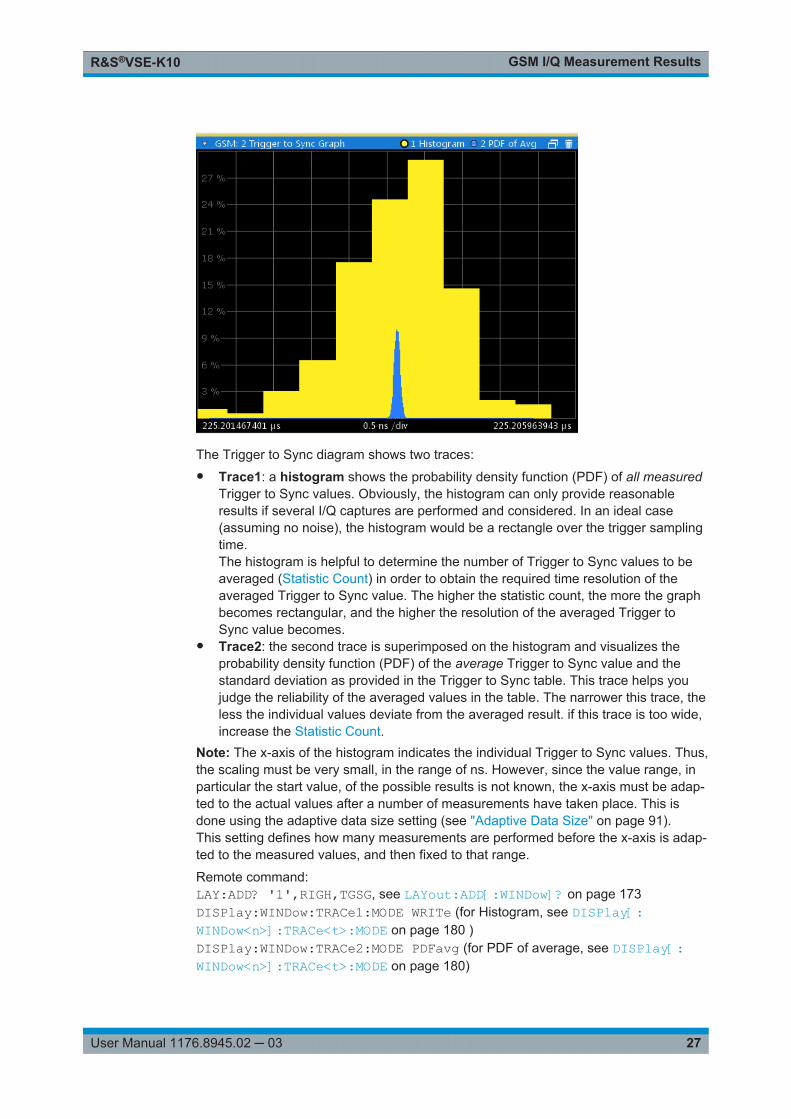
The Trigger to Sync diagram shows two traces:● Trace1: a histogram shows the probability density function (PDF) of all measured
Trigger to Sync values. Obviously, the histogram can only provide reasonableresults if several I/Q captures are performed and considered. In an ideal case(assuming no noise), the histogram would be a rectangle over the trigger samplingtime.The histogram is helpful to determine the number of Trigger to Sync values to beaveraged (Statistic Count) in order to obtain the required time resolution of theaveraged Trigger to Sync value. The higher the statistic count, the more the graphbecomes rectangular, and the higher the resolution of the averaged Trigger toSync value becomes.
● Trace2: the second trace is superimposed on the histogram and visualizes theprobability density function (PDF) of the average Trigger to Sync value and thestandard deviation as provided in the Trigger to Sync table. This trace helps youjudge the reliability of the averaged values in the table. The narrower this trace, theless the individual values deviate from the averaged result. if this trace is too wide,increase the Statistic Count.
Note: The x-axis of the histogram indicates the individual Trigger to Sync values. Thus,the scaling must be very small, in the range of ns. However, since the value range, inparticular the start value, of the possible results is not known, the x-axis must be adap-ted to the actual values after a number of measurements have taken place. This isdone using the adaptive data size setting (see "Adaptive Data Size" on page 91).This setting defines how many measurements are performed before the x-axis is adap-ted to the measured values, and then fixed to that range.
Remote command: LAY:ADD? '1',RIGH,TGSG, see LAYout:ADD[:WINDow]? on page 173DISPlay:WINDow:TRACe1:MODE WRITe (for Histogram, see DISPlay[:WINDow<n>]:TRACe<t>:MODE on page 180 )DISPlay:WINDow:TRACe2:MODE PDFavg (for PDF of average, see DISPlay[:WINDow<n>]:TRACe<t>:MODE on page 180)
GSM I/Q Measurement ResultsR&S®VSE-K10
28User Manual 1176.8945.02 ─ 03
Results:TRACe<n>[:DATA]? on page 196TRACe<n>[:DATA]:X? on page 197
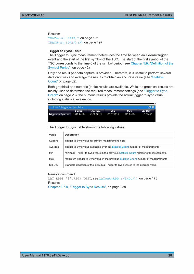
Trigger to Sync TableThe Trigger to Sync measurement determines the time between an external triggerevent and the start of the first symbol of the TSC. The start of the first symbol of theTSC corresponds to the time 0 of the symbol period (see Chapter 5.9, "Definition of theSymbol Period", on page 42).
Only one result per data capture is provided. Therefore, it is useful to perform severaldata captures and average the results to obtain an accurate value (see "StatisticCount" on page 82).
Both graphical and numeric (table) results are available. While the graphical results aremainly used to determine the required measurement settings (see "Trigger to SyncGraph" on page 26), the numeric results provide the actual trigger to sync value,including statistical evaluation.
The Trigger to Sync table shows the following values:
Value Description
Current Trigger to Sync value for current measurement in μs
Average Trigger to Sync value averaged over the Statistic Count number of measurements
Min Minimum Trigger to Sync value in the previous Statistic Count number of measurements
Max Maximum Trigger to Sync value in the previous Statistic Count number of measurements
Std Dev Standard deviation of the individual Trigger to Sync values to the average value
Remote command: LAY:ADD? '1',RIGH,TGST, see LAYout:ADD[:WINDow]? on page 173Results:Chapter 9.7.8, "Trigger to Sync Results", on page 228
Basics on GSM MeasurementsR&S®VSE-K10
29User Manual 1176.8945.02 ─ 03
5 Basics on GSM MeasurementsSome background knowledge on basic terms and principles used in GSM measure-ments is provided here for a better understanding of the required configuration set-tings.
5.1 Relevant Digital Standards
The measurements and the physical layer – the layer of the GSM network on whichmodulation, transmission of RF signals, reception of RF signals, and demodulationtake place – is defined in the standards:
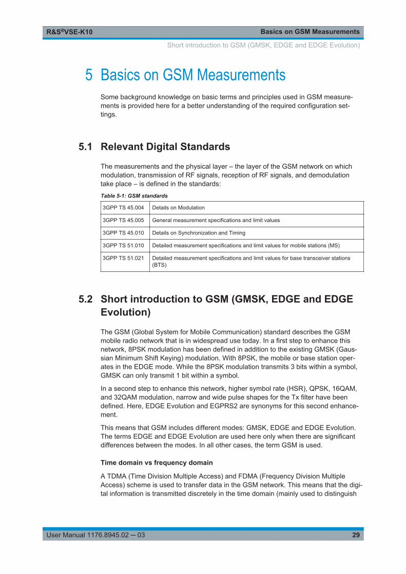
Table 5-1: GSM standards
3GPP TS 45.004 Details on Modulation
3GPP TS 45.005 General measurement specifications and limit values
3GPP TS 45.010 Details on Synchronization and Timing
3GPP TS 51.010 Detailed measurement specifications and limit values for mobile stations (MS)
3GPP TS 51.021 Detailed measurement specifications and limit values for base transceiver stations(BTS)
5.2 Short introduction to GSM (GMSK, EDGE and EDGEEvolution)
The GSM (Global System for Mobile Communication) standard describes the GSMmobile radio network that is in widespread use today. In a first step to enhance thisnetwork, 8PSK modulation has been defined in addition to the existing GMSK (Gaus-sian Minimum Shift Keying) modulation. With 8PSK, the mobile or base station oper-ates in the EDGE mode. While the 8PSK modulation transmits 3 bits within a symbol,GMSK can only transmit 1 bit within a symbol.
In a second step to enhance this network, higher symbol rate (HSR), QPSK, 16QAM,and 32QAM modulation, narrow and wide pulse shapes for the Tx filter have beendefined. Here, EDGE Evolution and EGPRS2 are synonyms for this second enhance-ment.
This means that GSM includes different modes: GMSK, EDGE and EDGE Evolution.The terms EDGE and EDGE Evolution are used here only when there are significantdifferences between the modes. In all other cases, the term GSM is used.
Time domain vs frequency domain
A TDMA (Time Division Multiple Access) and FDMA (Frequency Division MultipleAccess) scheme is used to transfer data in the GSM network. This means that the digi-tal information is transmitted discretely in the time domain (mainly used to distinguish
Short introduction to GSM (GMSK, EDGE and EDGE Evolution)
Basics on GSM MeasurementsR&S®VSE-K10
30User Manual 1176.8945.02 ─ 03
between different users) as well as in the frequency domain (mainly used to distinguishbetween BTS).
Slots and frames
The time domain is divided into slots with a duration of 576.923 µs (exactly: 3/5200 s).8 slots (numbered 0 to 7) are combined into 1 frame with a duration of approximately4.6154 ms (exactly: 3/650 s).
Multiframes and superframesFrames can be grouped into a multiframe consisting of either 26 (for support traffic andassociated control channels) or 51 (for all other purposes) frames. Multiframes can begrouped to superframes consisting of either 51 26-frame or 26 51-frame multiframes.Multiframes and superframes are not of relevance for the physical measurements onthe GSM system and thus not discussed in detail here.
A mobile phone, therefore, does not communicate continuously with the base station;instead, it communicates discretely in individual slots assigned by the base station dur-ing connection and call establishment. In the simplest case, 8 mobiles share the 8 slotsof a frame (TDMA).
Frequency bands and channels
The frequency range assigned to GSM is divided into frequency bands, and eachband, in turn, is subdivided into channels.
Each frequency channel is identified by its center frequency and a number, known asthe ARFCN (Absolute Radio Frequency Channel Number), which identifies the fre-quency channel within the specific frequency band. The GSM channel spacing is 200kHz.
Communication between a mobile and a base station can be either frequency-continu-ous or frequency-discrete – distributed across various frequency channels (FDMA). Inthe standard, the abbreviation "SFH" (slow frequency hopping) is used to designate thelatter mode of communication.
Uplink and downlink
Base stations and mobiles communicate in different frequency ranges; the mobilesends in the "uplink" (UL), and the base station in the "downlink" (DL).
The frequencies specified in the standard plus their channel numbers (ARFCN) areshown in the figure and table below.
Short introduction to GSM (GMSK, EDGE and EDGE Evolution)
Basics on GSM MeasurementsR&S®VSE-K10
31User Manual 1176.8945.02 ─ 03
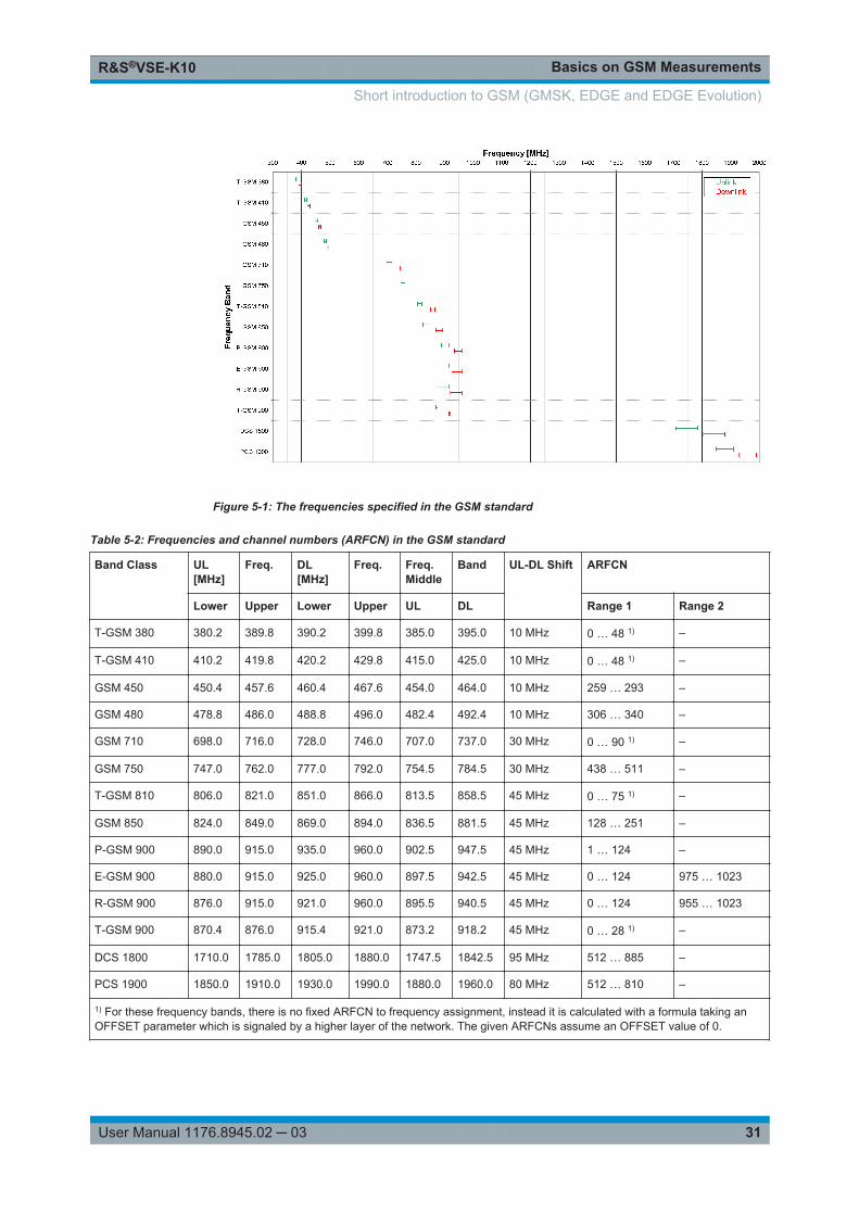
Figure 5-1: The frequencies specified in the GSM standard
Table 5-2: Frequencies and channel numbers (ARFCN) in the GSM standard
Band Class UL[MHz]
Freq. DL[MHz]
Freq. Freq.Middle
Band UL-DL Shift ARFCN
Lower Upper Lower Upper UL DL Range 1 Range 2
T-GSM 380 380.2 389.8 390.2 399.8 385.0 395.0 10 MHz 0 … 48 1) –
T-GSM 410 410.2 419.8 420.2 429.8 415.0 425.0 10 MHz 0 … 48 1) –
GSM 450 450.4 457.6 460.4 467.6 454.0 464.0 10 MHz 259 … 293 –
GSM 480 478.8 486.0 488.8 496.0 482.4 492.4 10 MHz 306 … 340 –
GSM 710 698.0 716.0 728.0 746.0 707.0 737.0 30 MHz 0 … 90 1) –
GSM 750 747.0 762.0 777.0 792.0 754.5 784.5 30 MHz 438 … 511 –
T-GSM 810 806.0 821.0 851.0 866.0 813.5 858.5 45 MHz 0 … 75 1) –
GSM 850 824.0 849.0 869.0 894.0 836.5 881.5 45 MHz 128 … 251 –
P-GSM 900 890.0 915.0 935.0 960.0 902.5 947.5 45 MHz 1 … 124 –
E-GSM 900 880.0 915.0 925.0 960.0 897.5 942.5 45 MHz 0 … 124 975 … 1023
R-GSM 900 876.0 915.0 921.0 960.0 895.5 940.5 45 MHz 0 … 124 955 … 1023
T-GSM 900 870.4 876.0 915.4 921.0 873.2 918.2 45 MHz 0 … 28 1) –
DCS 1800 1710.0 1785.0 1805.0 1880.0 1747.5 1842.5 95 MHz 512 … 885 –
PCS 1900 1850.0 1910.0 1930.0 1990.0 1880.0 1960.0 80 MHz 512 … 810 –
1) For these frequency bands, there is no fixed ARFCN to frequency assignment, instead it is calculated with a formula taking anOFFSET parameter which is signaled by a higher layer of the network. The given ARFCNs assume an OFFSET value of 0.
Short introduction to GSM (GMSK, EDGE and EDGE Evolution)
Basics on GSM MeasurementsR&S®VSE-K10
32User Manual 1176.8945.02 ─ 03
Modulation modes
Different modulation modes are used in the GSM mobile radio network. The originalGSM modulation is GMSK, with the normal symbol rate (NSR) of approximately270.833 ksymb/s (exactly: 1625/6 ksymb/s). This corresponds to a bit rate of 270.833kbit/s. The details are specified in chapter 2 of "3GPP TS 45.004" (see Table 5-1).
The 8PSK (Phase Shift Keying) modulation, which is used within EDGE, was intro-duced to increase the data rate on the physical link. It uses the same symbol rate (thenormal symbol rate) as GMSK (270.833 ksymb/s), but has a bit rate of 3 × 270.833kbit/s (exactly: 812.5 kbit/s).
In this method, three bits represent a symbol. The details are specified in chapter 3"3GPP TS 45.004" (see Table 5-1).
The 16QAM and 32QAM (Quadrature Amplitude Modulation) modulation, which areused in EDGE Evolution, were introduced to further increase the data rate on the phys-ical link. They use the normal symbol rate (270.833 ksymb/s), but have bit rates of 4 ×270.833 kbit/s or 5 × 270.833 kbit/s, respectively. The details are specified in chapter 4"3GPP TS 45.004" (see Table 5-1).
The QPSK, 16QAM and 32QAM modulation with a higher symbol rate, which are usedin EDGE Evolution, were introduced to further increase the data rate on the physicallink. They use a higher symbol rate (325 ksymb/s), but have bit rates of 2 × 325 kbit/s,4 × 325 kbit/s or 5 × 325 kbit/s, respectively. The details are specified in chapter 5"3GPP TS 45.004" (see Table 5-1).
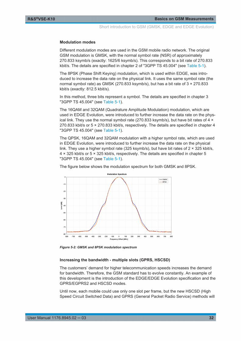
The figure below shows the modulation spectrum for both GMSK and 8PSK.
Figure 5-2: GMSK and 8PSK modulation spectrum
Increasing the bandwidth - multiple slots (GPRS, HSCSD)
The customers’ demand for higher telecommunication speeds increases the demandfor bandwidth. Therefore, the GSM standard has to evolve constantly. An example ofthis development is the introduction of the EDGE/EDGE Evolution specification and theGPRS/EGPRS2 and HSCSD modes.
Until now, each mobile could use only one slot per frame, but the new HSCSD (HighSpeed Circuit Switched Data) and GPRS (General Packet Radio Service) methods will
Short introduction to GSM (GMSK, EDGE and EDGE Evolution)
Basics on GSM MeasurementsR&S®VSE-K10
33User Manual 1176.8945.02 ─ 03
allow permanent assignment of more than one slot per mobile, plus dynamic utilizationof multiple slots.
The concept behind GPRS is dynamic assignment of up to 8 slots to each mobile fordata transmission, depending on demand (and availability in the network).
HSCSD allows permanent assignment of up to 4 slots to a mobile.
Normal and higher symbol rates
The modulation modes GMSK, QPSK, 8PSK, 16QAM and 32QAM can be used witheither normal or higher symbol rate and different Tx filters.
What is significant for the R&S VSE GSM application in this respect is that the mobilecan send power on a frequency in more than one slot.
5.3 Short Introduction to VAMOS
The "Voice services over Adaptive Multi-user Channels on One Slot" (VAMOS) exten-sion to the GSM standard allows transmission of two GMSK users simultaneouslywithin a single time slot.
Subchannels
The standard specifies the downlink signal using Adaptive QPSK (AQPSK) modulation(see 3GPP TS 45.004), where two "subchannel" binary sequences are multiplexed toform a single QPSK sequence. The ratio of powers for the subchannels is referred toas the "Subchannel Power Imbalance Ratio" (SCPIR). One of the subchannels is inter-preted as interference. The value of SCPIR affects the shape of the AQPSK constella-tion. For an SCPIR of 0dB the constellation is square (as in "normal" QSPK), while forother values of the SCPIR the constellation becomes rectangular.
Training sequences (TSCs)
A new set of training sequences (TSCs) has also been proposed (see 3GPP TS45.002) for GMSK signals. The previous TSCs for GMSK bursts are listed as "Set 1",while the new TSCs are listed as "Set 2". AQPSK signals can be formed using TSCsfrom Set 1 on the first subchannel and TSCs from either Set 1 or Set 2 on the secondsubchannel. In case a TSC from Set 2 is used, it should match the TSC from Set 1, i.e.TSC<n> from Set 1 on subchannel 1 should match TSC<n> from Set 2 on subchannel2, for n = 0..7.
TSC vs "Midamble"The terms TSC and Midamble are used synonymously in the standard. In this docu-mentation, we use the term TSC to refer to the known symbol sequence in the middleof the slot.
The R&S VSE GSM application supports measurement of the following signals:
● GMSK bursts using the TSCs from Set 1 or Set 2
Short Introduction to VAMOS
Basics on GSM MeasurementsR&S®VSE-K10
34User Manual 1176.8945.02 ─ 03
● AQPSK bursts with combinations of TSCs from Set 1 and 2 on the subchannels● AQPSK bursts with a user-specified SCPIR
The following measurements of the above signals are supported:
● Power vs Time● Demod (Modulation Accuracy, EVM vs Time, Phase Error vs Time, Magnitude
Error vs Time, Constellation)● Spectrum (modulation, transient) including limit check● Automatic trigger offset detection
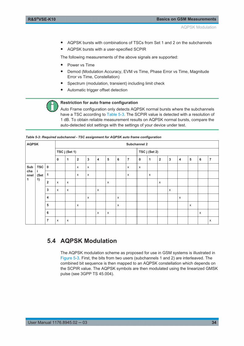
Restriction for auto frame configurationAuto Frame configuration only detects AQPSK normal bursts where the subchannelshave a TSC according to Table 5-3. The SCPIR value is detected with a resolution of1 dB. To obtain reliable measurement results on AQPSK normal bursts, compare theauto-detected slot settings with the settings of your device under test.
Table 5-3: Required subchannel - TSC assignment for AQPSK auto frame configuration
AQPSK Subchannel 2
TSC j (Set 1) TSC j (Set 2)
0 1 2 3 4 5 6 7 0 1 2 3 4 5 6 7
Subchannel1
TSCi(Set1)
0 x x x x
1 x x x x
2 x x x x
3 x x x x
4 x x x
5 x x x
6 x x x
7 x x x
5.4 AQPSK Modulation
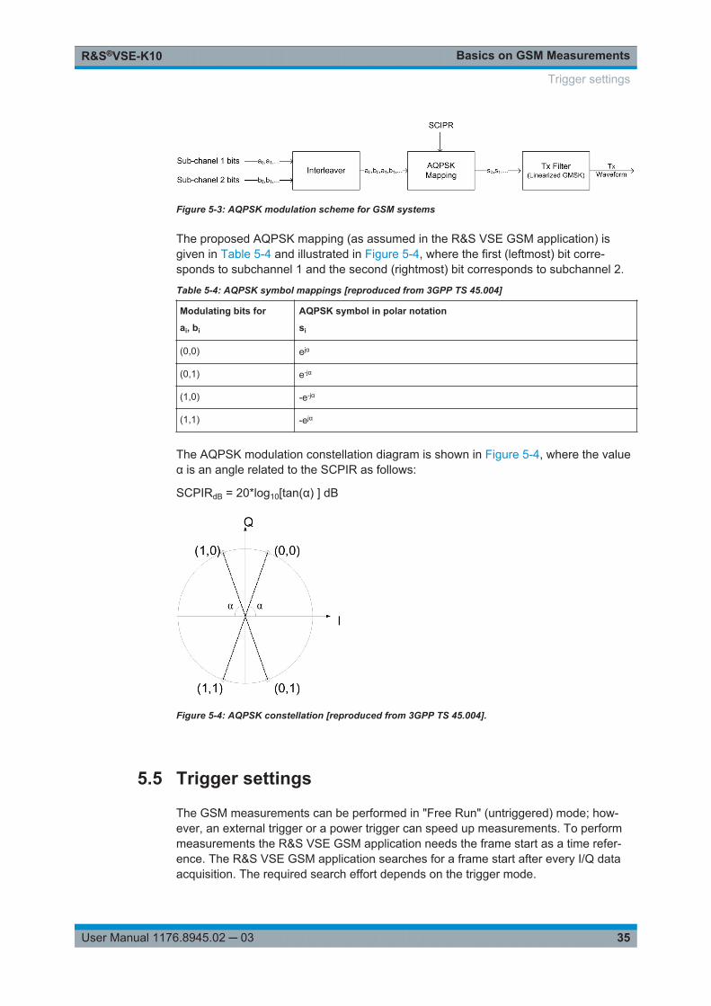
The AQPSK modulation scheme as proposed for use in GSM systems is illustrated inFigure 5-3. First, the bits from two users (subchannels 1 and 2) are interleaved. Thecombined bit sequence is then mapped to an AQPSK constellation which depends onthe SCPIR value. The AQPSK symbols are then modulated using the linearized GMSKpulse (see 3GPP TS 45.004).
AQPSK Modulation
Basics on GSM MeasurementsR&S®VSE-K10
35User Manual 1176.8945.02 ─ 03
Figure 5-3: AQPSK modulation scheme for GSM systems
The proposed AQPSK mapping (as assumed in the R&S VSE GSM application) isgiven in Table 5-4 and illustrated in Figure 5-4, where the first (leftmost) bit corre-sponds to subchannel 1 and the second (rightmost) bit corresponds to subchannel 2.
Table 5-4: AQPSK symbol mappings [reproduced from 3GPP TS 45.004]
Modulating bits for
ai, bi
AQPSK symbol in polar notation
si
(0,0) ejα
(0,1) e-jα
(1,0) -e-jα
(1,1) -ejα
The AQPSK modulation constellation diagram is shown in Figure 5-4, where the valueα is an angle related to the SCPIR as follows:
SCPIRdB = 20*log10[tan(α) ] dB
Figure 5-4: AQPSK constellation [reproduced from 3GPP TS 45.004].
5.5 Trigger settings
The GSM measurements can be performed in "Free Run" (untriggered) mode; how-ever, an external trigger or a power trigger can speed up measurements. To performmeasurements the R&S VSE GSM application needs the frame start as a time refer-ence. The R&S VSE GSM application searches for a frame start after every I/Q dataacquisition. The required search effort depends on the trigger mode.
Trigger settings
Basics on GSM MeasurementsR&S®VSE-K10
36User Manual 1176.8945.02 ─ 03
Consider the following trigger mode settings:
● In "Free Run" mode, i.e. without any trigger, the R&S VSE GSM application totallyrelies on the frame/slot configuration to find the frame start. The start of a measure-ment is not triggered. Once a measurement is completed, another is started imme-diately. For an unambiguous frame configuration, the GSM application searches forthe frame start inside the captured I/Q data. This is the slowest frame searchmode.
● With a "Power Trigger", the measurement is triggered by the power ramp of thereceived GSM bursts. Nevertheless the R&S VSE GSM application still relies onthe frame/slot configuration to find the frame start inside the captured I/Q data.Once a measurement is completed, the R&S VSE GSM application waits for thenext trigger event to start the next measurement. The search for the frame start isas in "Free Run" mode, except that the I/Q data capture is triggered.
● With the "External Trigger", the measurement is triggered by an external signal(connected to the "EXT TRIGGER" input of the connected instrument). The R&SVSE GSM application assumes that the frame start (i.e. the "active part" in slot 0)directly follows the trigger event. An external trigger requires a correct setting of thetrigger offset. The search is faster compared to the free run and power triggermodes. Use an external trigger to maximize the measurement speed or if the frameconfiguration is ambiguous (i.e. if the slot properties are cyclic with a cycle lessthan the frame duration).
Refer to Chapter 6.4, "Trigger Settings", on page 76 to learn more about appropriatetrigger settings and to Chapter 6.2, "Signal Description", on page 56 for informationon the frame/slot configuration.
Refer to "Automatic Trigger Offset" on page 92 to learn more about setting the triggeroffset automatically.
5.6 Defining the Scope of the Measurement
The R&S VSE GSM application is slot-based. It can measure up to 8 consecutive GSMslots (1 frame) and store the power results for all slots ("Power vs Time" and "Power vsSlot" measurements, see "PvT Full Burst" on page 22 and "Power vs Slot"on page 21).
In previous Rohde & Schwarz signal and spectrum analyzers, the term "burst" wasused synonymously for "slot". In this documentation, we use the term "burst" when thesignal behaves like a pulse, i.e. power is ramped up and down. The up ramp is referredto as the rising edge, the down ramp as the falling edge. A burst may occur within oneor more slots, which is a measure of time in the captured signal. Thus, a burst maycoincide with a slot, but it must not necessarily do so.Usually only slots in which a burst is expected are of interest. Such slots are defined asactive slots in the signal description.
Within this slot scope (defined by First Slot to measure and Number of Slots to mea-sure), a single slot ( Slot to Measure) is selected for a more detailed analysis (e.g.
Defining the Scope of the Measurement
Basics on GSM MeasurementsR&S®VSE-K10
37User Manual 1176.8945.02 ─ 03
"Modulation Accuracy" measurement, see "Modulation Accuracy" on page 15). TheSlot to Measure is required for the following reasons:
● To provide the reference power and time reference for the "Power vs Time" mea-surement (see "PvT Full Burst" on page 22). Typically, the masks for all slots aretime-aligned according to the timing of the Slot to Measure (see "Limit Line TimeAlignment" on page 88).
● All "Modulation Spectrum" results are based on the Slot to Measure (see "Modula-tion Spectrum Graph" on page 17). (The results of all "Transient Spectrum" dia-grams are based on the slot scope, i.e. on the interval defined by the First Slot tomeasure and the Number of Slots to measure, see "Transient Spectrum Graph"on page 24).
● All results that require demodulation of one slot and statistical analysis (e.g. Modu-lation Accuracy, Phase Error, and EVM) are based on the Slot to Measure.
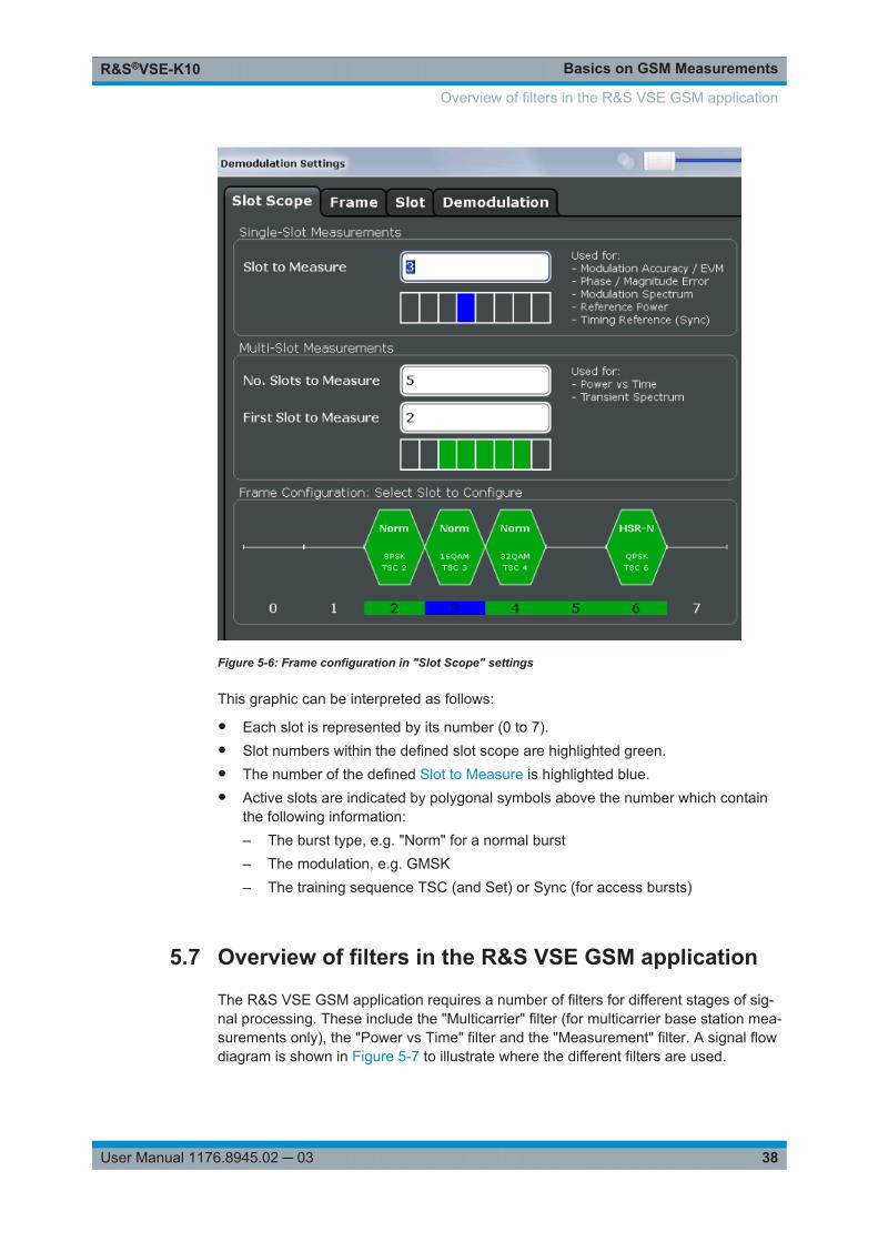
The slot scope is defined in the "Demodulation Settings" (see Chapter 6.6.1, "SlotScope", on page 82), and it is indicated by a filled green box in the "Frame Configu-ration" (see Figure 5-6). The Slot to Measure is indicated by a filled blue box.
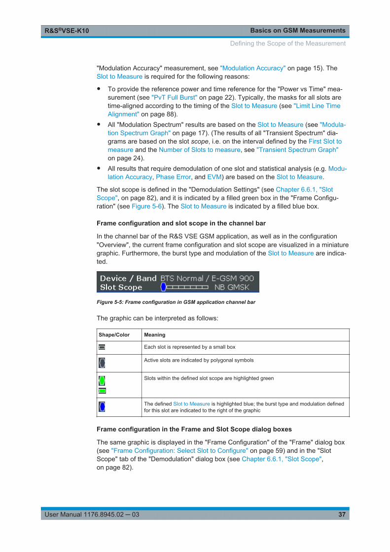
Frame configuration and slot scope in the channel bar
In the channel bar of the R&S VSE GSM application, as well as in the configuration"Overview", the current frame configuration and slot scope are visualized in a miniaturegraphic. Furthermore, the burst type and modulation of the Slot to Measure are indica-ted.
Figure 5-5: Frame configuration in GSM application channel bar
The graphic can be interpreted as follows:
Shape/Color Meaning
Each slot is represented by a small box
Active slots are indicated by polygonal symbols
Slots within the defined slot scope are highlighted green
The defined Slot to Measure is highlighted blue; the burst type and modulation definedfor this slot are indicated to the right of the graphic
Frame configuration in the Frame and Slot Scope dialog boxes
The same graphic is displayed in the "Frame Configuration" of the "Frame" dialog box(see "Frame Configuration: Select Slot to Configure" on page 59) and in the "SlotScope" tab of the "Demodulation" dialog box (see Chapter 6.6.1, "Slot Scope",on page 82).
Defining the Scope of the Measurement
Basics on GSM MeasurementsR&S®VSE-K10
38User Manual 1176.8945.02 ─ 03
Figure 5-6: Frame configuration in "Slot Scope" settings
This graphic can be interpreted as follows:
● Each slot is represented by its number (0 to 7).● Slot numbers within the defined slot scope are highlighted green.● The number of the defined Slot to Measure is highlighted blue.● Active slots are indicated by polygonal symbols above the number which contain
the following information:– The burst type, e.g. "Norm" for a normal burst– The modulation, e.g. GMSK– The training sequence TSC (and Set) or Sync (for access bursts)
5.7 Overview of filters in the R&S VSE GSM application
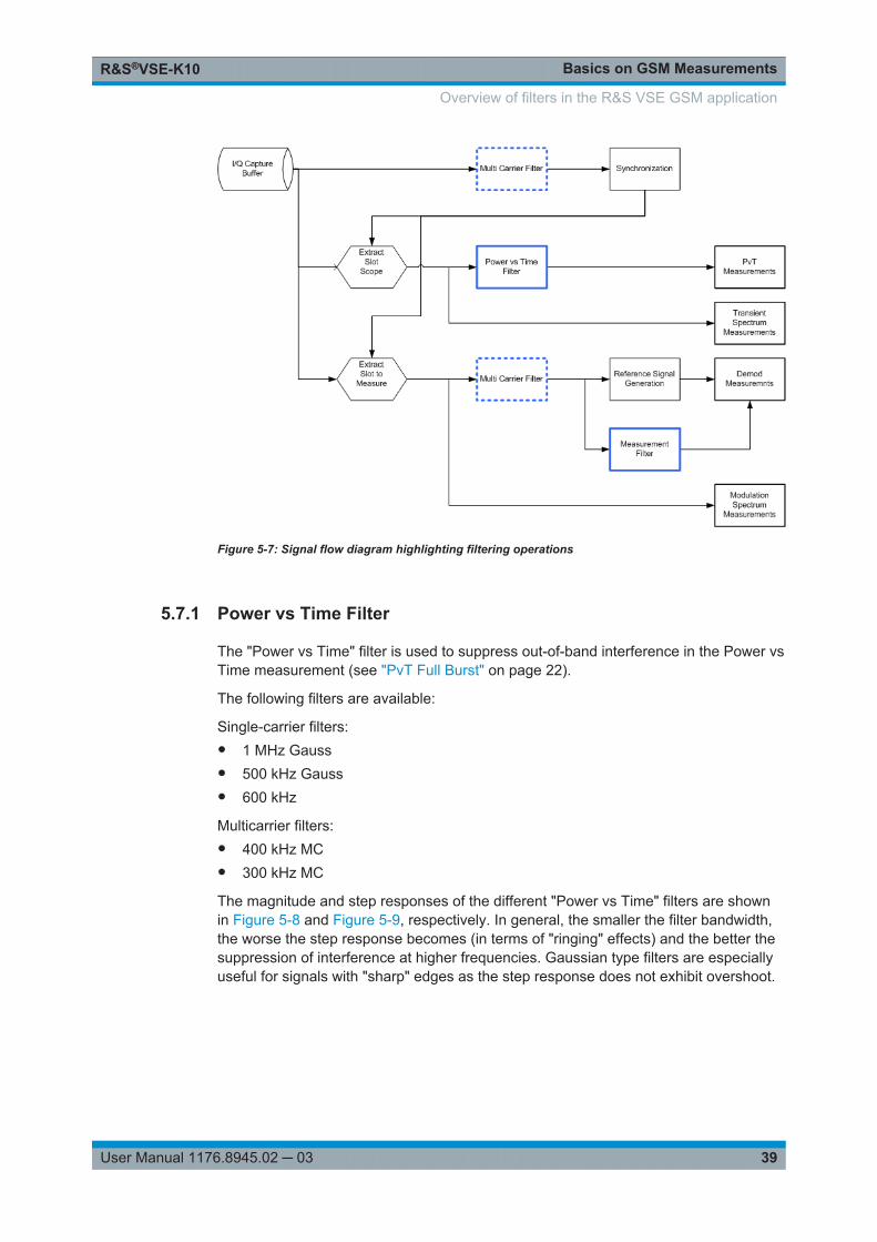
The R&S VSE GSM application requires a number of filters for different stages of sig-nal processing. These include the "Multicarrier" filter (for multicarrier base station mea-surements only), the "Power vs Time" filter and the "Measurement" filter. A signal flowdiagram is shown in Figure 5-7 to illustrate where the different filters are used.
Overview of filters in the R&S VSE GSM application
Basics on GSM MeasurementsR&S®VSE-K10
39User Manual 1176.8945.02 ─ 03
Figure 5-7: Signal flow diagram highlighting filtering operations
5.7.1 Power vs Time Filter
The "Power vs Time" filter is used to suppress out-of-band interference in the Power vsTime measurement (see "PvT Full Burst" on page 22).
The following filters are available:
Single-carrier filters:● 1 MHz Gauss● 500 kHz Gauss● 600 kHz
Multicarrier filters:● 400 kHz MC● 300 kHz MC
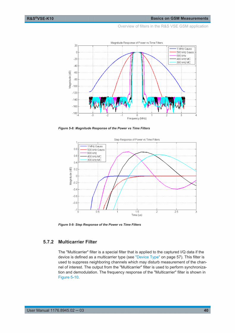
The magnitude and step responses of the different "Power vs Time" filters are shownin Figure 5-8 and Figure 5-9, respectively. In general, the smaller the filter bandwidth,the worse the step response becomes (in terms of "ringing" effects) and the better thesuppression of interference at higher frequencies. Gaussian type filters are especiallyuseful for signals with "sharp" edges as the step response does not exhibit overshoot.
Overview of filters in the R&S VSE GSM application
Basics on GSM MeasurementsR&S®VSE-K10
40User Manual 1176.8945.02 ─ 03
Figure 5-8: Magnitude Response of the Power vs Time Filters
Figure 5-9: Step Response of the Power vs Time Filters
5.7.2 Multicarrier Filter
The "Multicarrier" filter is a special filter that is applied to the captured I/Q data if thedevice is defined as a multicarrier type (see "Device Type" on page 57). This filter isused to suppress neighboring channels which may disturb measurement of the chan-nel of interest. The output from the "Multicarrier" filter is used to perform synchroniza-tion and demodulation. The frequency response of the "Multicarrier" filter is shown inFigure 5-10.
Overview of filters in the R&S VSE GSM application
Basics on GSM MeasurementsR&S®VSE-K10
41User Manual 1176.8945.02 ─ 03
Figure 5-10: Frequency Response of the Multicarrier Filter
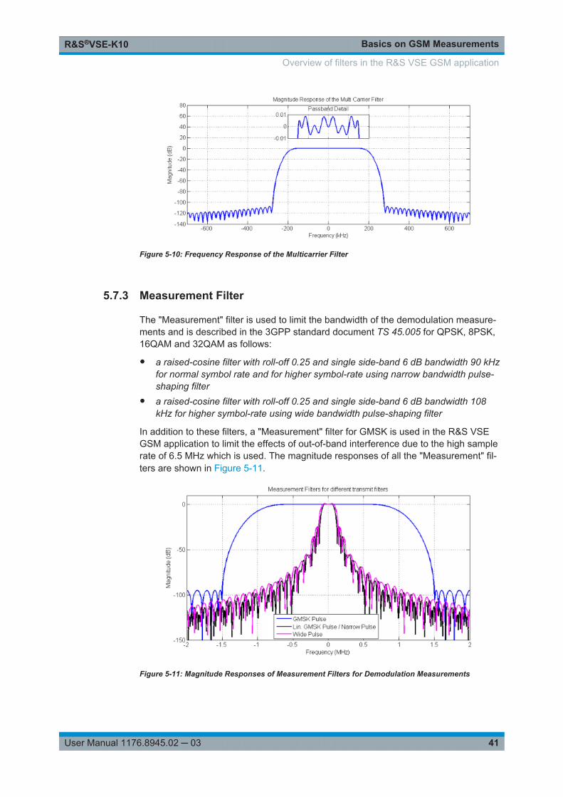
5.7.3 Measurement Filter
The "Measurement" filter is used to limit the bandwidth of the demodulation measure-ments and is described in the 3GPP standard document TS 45.005 for QPSK, 8PSK,16QAM and 32QAM as follows:
● a raised-cosine filter with roll-off 0.25 and single side-band 6 dB bandwidth 90 kHzfor normal symbol rate and for higher symbol-rate using narrow bandwidth pulse-shaping filter
● a raised-cosine filter with roll-off 0.25 and single side-band 6 dB bandwidth 108kHz for higher symbol-rate using wide bandwidth pulse-shaping filter
In addition to these filters, a "Measurement" filter for GMSK is used in the R&S VSEGSM application to limit the effects of out-of-band interference due to the high samplerate of 6.5 MHz which is used. The magnitude responses of all the "Measurement" fil-ters are shown in Figure 5-11.
Figure 5-11: Magnitude Responses of Measurement Filters for Demodulation Measurements
Overview of filters in the R&S VSE GSM application
Basics on GSM MeasurementsR&S®VSE-K10
42User Manual 1176.8945.02 ─ 03
5.8 Dependency of Slot Parameters
The parameters that define a slot used for a GSM measurement are dependent oneach other, and only the following combinations of these parameters are available inthe R&S VSE GSM application (see Chapter 6.2.3, "Slot Settings", on page 59).
Table 5-5: Dependency of slot parameters
Burst Type Modulation Filter TSC
AB GMSK GMSK Pulse TS 0, TS 1, TS 2
User
HSR QPSK, 16QAM, 32QAM Narrow Pulse,
Wide Pulse
TSC 0, …, TSC 7
User
NB 8PSK, 16QAM, 32QAM Linearized GMSK Pulse TSC 0, …, TSC 7
User
AQPSK Linearized GMSK Pulse Subchannel 1:
TSC 0 (Set 1), …, TSC 7 (Set 1)
Subchannel 2:
TSC 0 (Set 1), …, TSC 7 (Set 1),
TSC 0 (Set 2), …, TSC 7 (Set 2)
Subchannel 1: User
Subchannel 2: User
GMSK GMSK Pulse TSC 0 (Set 1), …, TSC 7 (Set 1),
TSC 0 (Set 2), …, TSC 7 (Set 2)
User
5.9 Definition of the Symbol Period
The following sections define the symbol period for various modulation types.
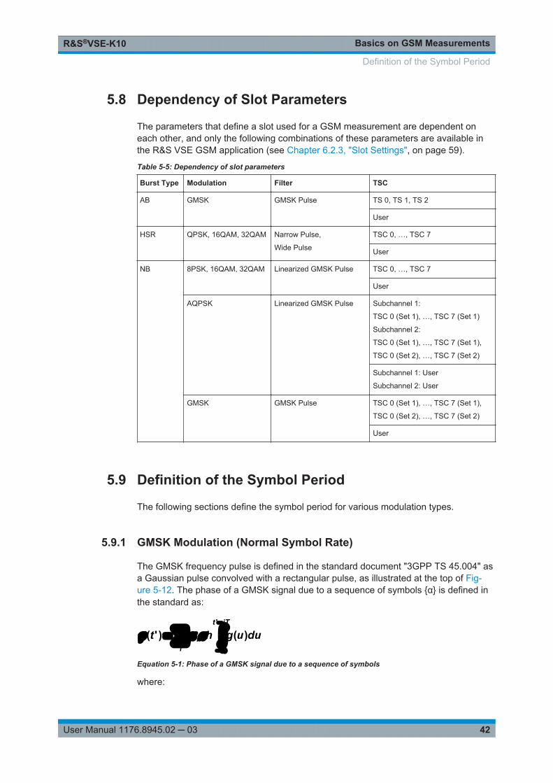
5.9.1 GMSK Modulation (Normal Symbol Rate)
The GMSK frequency pulse is defined in the standard document "3GPP TS 45.004" asa Gaussian pulse convolved with a rectangular pulse, as illustrated at the top of Fig-ure 5-12. The phase of a GMSK signal due to a sequence of symbols {α} is defined inthe standard as:
iTt
ii duught
'
)()'(
Equation 5-1: Phase of a GMSK signal due to a sequence of symbols
where:
Definition of the Symbol Period
Basics on GSM MeasurementsR&S®VSE-K10
43User Manual 1176.8945.02 ─ 03
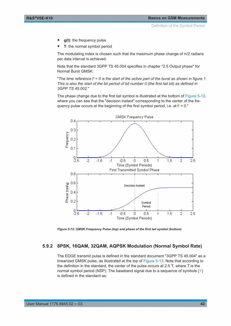
● g(t): the frequency pulse● T: the normal symbol period
The modulating index is chosen such that the maximum phase change of π/2 radiansper data interval is achieved.
Note that the standard 3GPP TS 45.004 specifies in chapter "2.5 Output phase" forNormal Burst GMSK:
"The time reference t' = 0 is the start of the active part of the burst as shown in figure 1.This is also the start of the bit period of bit number 0 (the first tail bit) as defined in3GPP TS 45.002."
The phase change due to the first tail symbol is illustrated at the bottom of Figure 5-12,where you can see that the "decision instant" corresponding to the center of the fre-quency pulse occurs at the beginning of the first symbol period, i.e. at t' = 0."
Figure 5-12: GMSK Frequency Pulse (top) and phase of the first tail symbol (bottom)
5.9.2 8PSK, 16QAM, 32QAM, AQPSK Modulation (Normal Symbol Rate)
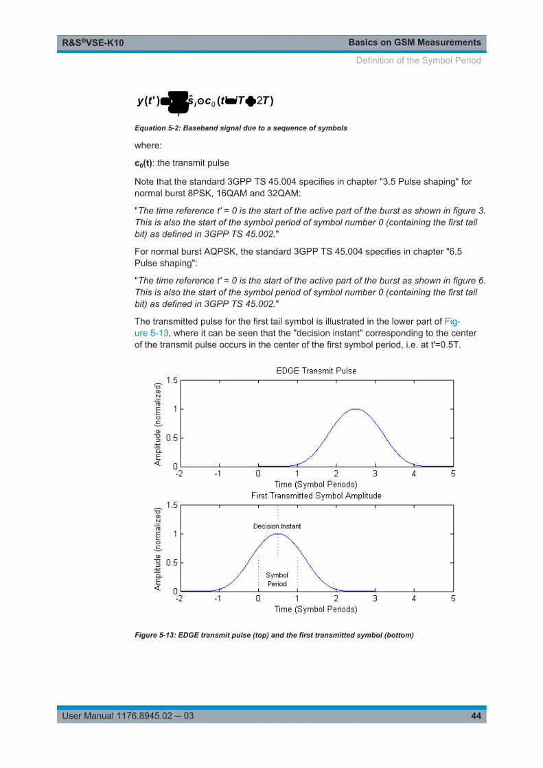
The EDGE transmit pulse is defined in the standard document "3GPP TS 45.004" as alinearized GMSK pulse, as illustrated at the top of Figure 5-13. Note that according tothe definition in the standard, the center of the pulse occurs at 2.5 T, where T is thenormal symbol period (NSP). The baseband signal due to a sequence of symbols { }is defined in the standard as:
Definition of the Symbol Period
Basics on GSM MeasurementsR&S®VSE-K10
44User Manual 1176.8945.02 ─ 03
i
i TiTtcsty )'(ˆ)'( 20
Equation 5-2: Baseband signal due to a sequence of symbols
where:
c0(t): the transmit pulse
Note that the standard 3GPP TS 45.004 specifies in chapter "3.5 Pulse shaping" fornormal burst 8PSK, 16QAM and 32QAM:
"The time reference t' = 0 is the start of the active part of the burst as shown in figure 3.This is also the start of the symbol period of symbol number 0 (containing the first tailbit) as defined in 3GPP TS 45.002."
For normal burst AQPSK, the standard 3GPP TS 45.004 specifies in chapter "6.5Pulse shaping":
"The time reference t' = 0 is the start of the active part of the burst as shown in figure 6.This is also the start of the symbol period of symbol number 0 (containing the first tailbit) as defined in 3GPP TS 45.002."
The transmitted pulse for the first tail symbol is illustrated in the lower part of Fig-ure 5-13, where it can be seen that the "decision instant" corresponding to the centerof the transmit pulse occurs in the center of the first symbol period, i.e. at t'=0.5T.
Figure 5-13: EDGE transmit pulse (top) and the first transmitted symbol (bottom)
Definition of the Symbol Period
Basics on GSM MeasurementsR&S®VSE-K10
45User Manual 1176.8945.02 ─ 03
The description above also applies to the 16QAM and 32QAM modulations defined forEDGE Evolution, using the "normal" symbol rate.
5.9.3 QPSK, 16QAM and 32QAM Modulation (Higher Symbol Rate)
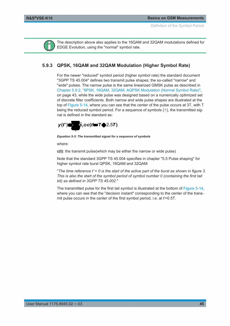
For the newer "reduced" symbol period (higher symbol rate) the standard document"3GPP TS 45.004" defines two transmit pulse shapes; the so-called "narrow" and"wide" pulses. The narrow pulse is the same linearized GMSK pulse as described inChapter 5.9.2, "8PSK, 16QAM, 32QAM, AQPSK Modulation (Normal Symbol Rate)",on page 43, while the wide pulse was designed based on a numerically optimized setof discrete filter coefficients. Both narrow and wide pulse shapes are illustrated at thetop of Figure 5-14, where you can see that the center of the pulse occurs at 3T, with Tbeing the reduced symbol period. For a sequence of symbols { }, the transmitted sig-nal is defined in the standard as:
i
i TiTtcsty ).'(ˆ)'( 52
Equation 5-3: The transmitted signal for a sequence of symbols
where:
c(t): the transmit pulse(which may be either the narrow or wide pulse)
Note that the standard 3GPP TS 45.004 specifies in chapter "5.5 Pulse shaping" forhigher symbol rate burst QPSK, 16QAM and 32QAM:
"The time reference t' = 0 is the start of the active part of the burst as shown in figure 3.This is also the start of the symbol period of symbol number 0 (containing the first tailbit) as defined in 3GPP TS 45.002."
The transmitted pulse for the first tail symbol is illustrated at the bottom of Figure 5-14,where you can see that the "decision instant" corresponding to the center of the trans-mit pulse occurs in the center of the first symbol period, i.e. at t'=0.5T.
Definition of the Symbol Period
Basics on GSM MeasurementsR&S®VSE-K10
46User Manual 1176.8945.02 ─ 03
Figure 5-14: EDGE Evolution transmit pulses (top) and the first transmitted symbols (bottom)
5.10 Synchronization
In order to detect and distinguish the individual slots and frames in the measured sig-nal, the known signal sequence (Sync or TSC) must be found in each frame.
The synchronization process in the R&S VSE GSM application depends on how or ifthe measurement is triggered.
Synchronization process for power trigger or free run mode
If a power trigger or no trigger is used (free run mode), the synchronization processconsists of the following steps:
1. Beginning at the start of a capture, the application searches for the synchronizationpattern (or TSC) of the Slot to Measure within one GSM frame length. This searchmust be performed over the entire area, as the time of occurrence of the TSCwithin the signal is not known. Thus, it is referred to as a "wide" search.
2. Once the synchronization point has been found, the application checks whetherenough samples remain in the capture buffer in order to analyze another frame. Ifso, the process continues with the next step.Otherwise, a new capture is started and the process begins with step 1 again.
Synchronization
Basics on GSM MeasurementsR&S®VSE-K10
47User Manual 1176.8945.02 ─ 03
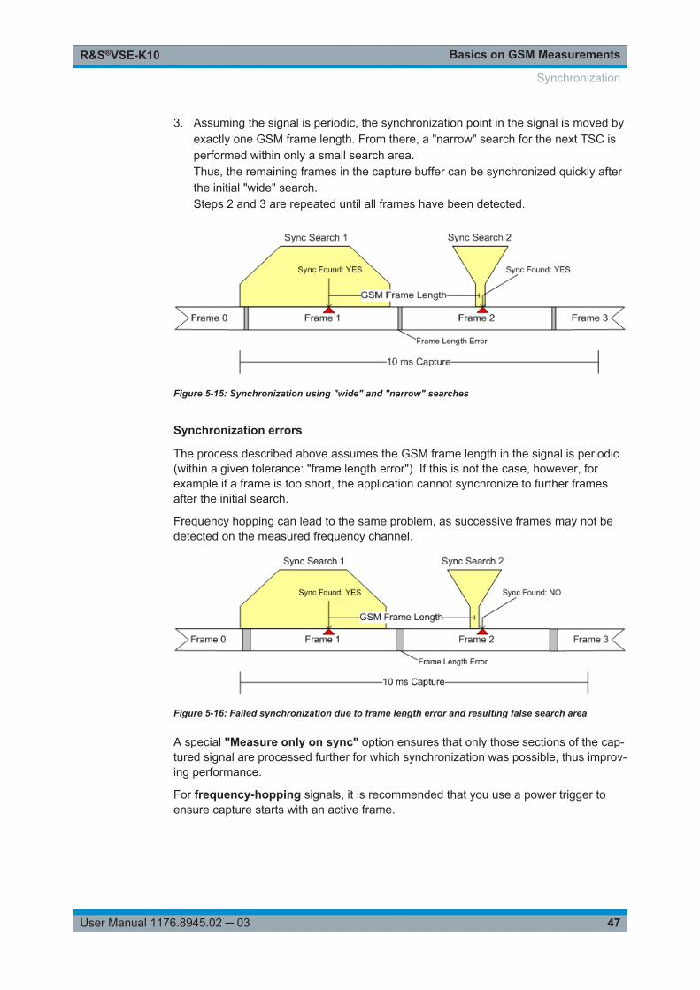
3. Assuming the signal is periodic, the synchronization point in the signal is moved byexactly one GSM frame length. From there, a "narrow" search for the next TSC isperformed within only a small search area.Thus, the remaining frames in the capture buffer can be synchronized quickly afterthe initial "wide" search.Steps 2 and 3 are repeated until all frames have been detected.
Figure 5-15: Synchronization using "wide" and "narrow" searches
Synchronization errors
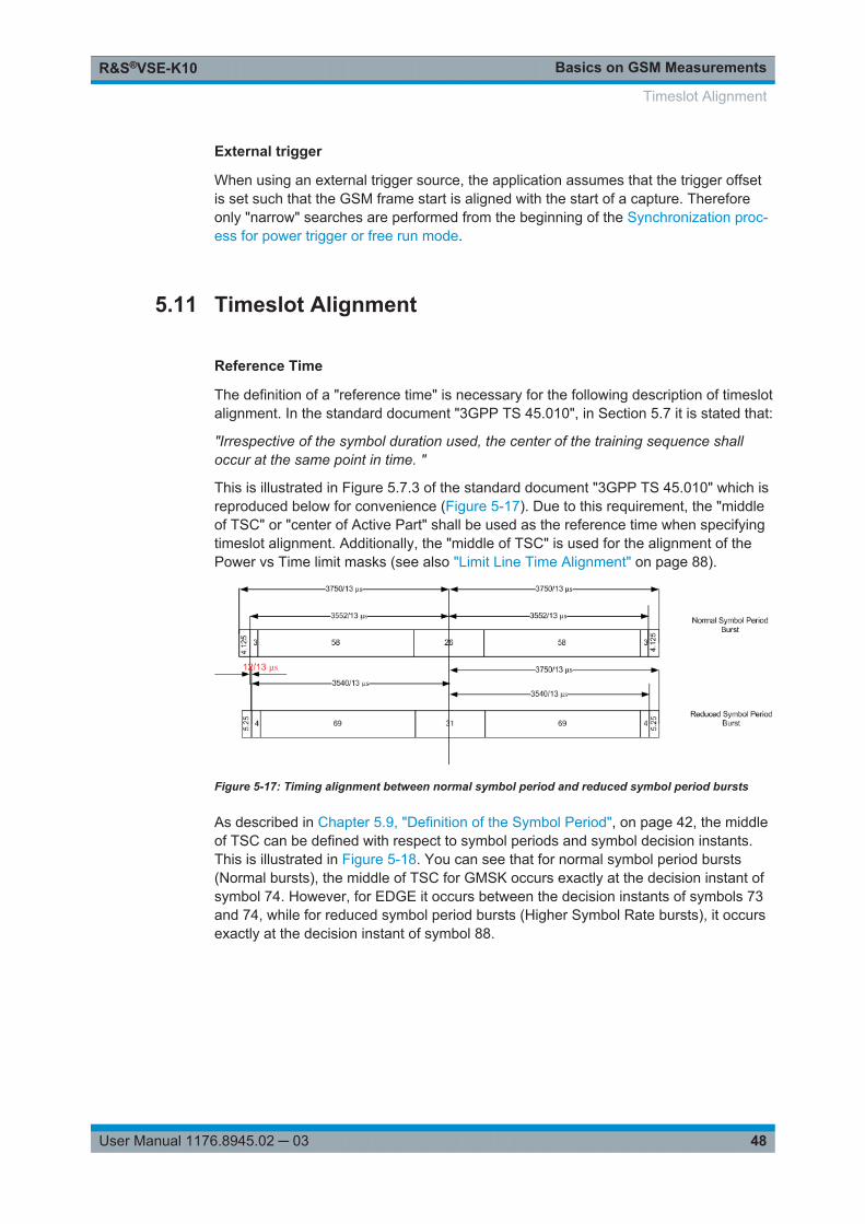
The process described above assumes the GSM frame length in the signal is periodic(within a given tolerance: "frame length error"). If this is not the case, however, forexample if a frame is too short, the application cannot synchronize to further framesafter the initial search.
Frequency hopping can lead to the same problem, as successive frames may not bedetected on the measured frequency channel.
Figure 5-16: Failed synchronization due to frame length error and resulting false search area
A special "Measure only on sync" option ensures that only those sections of the cap-tured signal are processed further for which synchronization was possible, thus improv-ing performance.
For frequency-hopping signals, it is recommended that you use a power trigger toensure capture starts with an active frame.
Synchronization
Basics on GSM MeasurementsR&S®VSE-K10
48User Manual 1176.8945.02 ─ 03
External trigger
When using an external trigger source, the application assumes that the trigger offsetis set such that the GSM frame start is aligned with the start of a capture. Thereforeonly "narrow" searches are performed from the beginning of the Synchronization proc-ess for power trigger or free run mode.
5.11 Timeslot Alignment
Reference Time
The definition of a "reference time" is necessary for the following description of timeslotalignment. In the standard document "3GPP TS 45.010", in Section 5.7 it is stated that:
"Irrespective of the symbol duration used, the center of the training sequence shalloccur at the same point in time. "
This is illustrated in Figure 5.7.3 of the standard document "3GPP TS 45.010" which isreproduced below for convenience (Figure 5-17). Due to this requirement, the "middleof TSC" or "center of Active Part" shall be used as the reference time when specifyingtimeslot alignment. Additionally, the "middle of TSC" is used for the alignment of thePower vs Time limit masks (see also "Limit Line Time Alignment" on page 88).
Figure 5-17: Timing alignment between normal symbol period and reduced symbol period bursts
As described in Chapter 5.9, "Definition of the Symbol Period", on page 42, the middleof TSC can be defined with respect to symbol periods and symbol decision instants.This is illustrated in Figure 5-18. You can see that for normal symbol period bursts(Normal bursts), the middle of TSC for GMSK occurs exactly at the decision instant ofsymbol 74. However, for EDGE it occurs between the decision instants of symbols 73and 74, while for reduced symbol period bursts (Higher Symbol Rate bursts), it occursexactly at the decision instant of symbol 88.
Timeslot Alignment
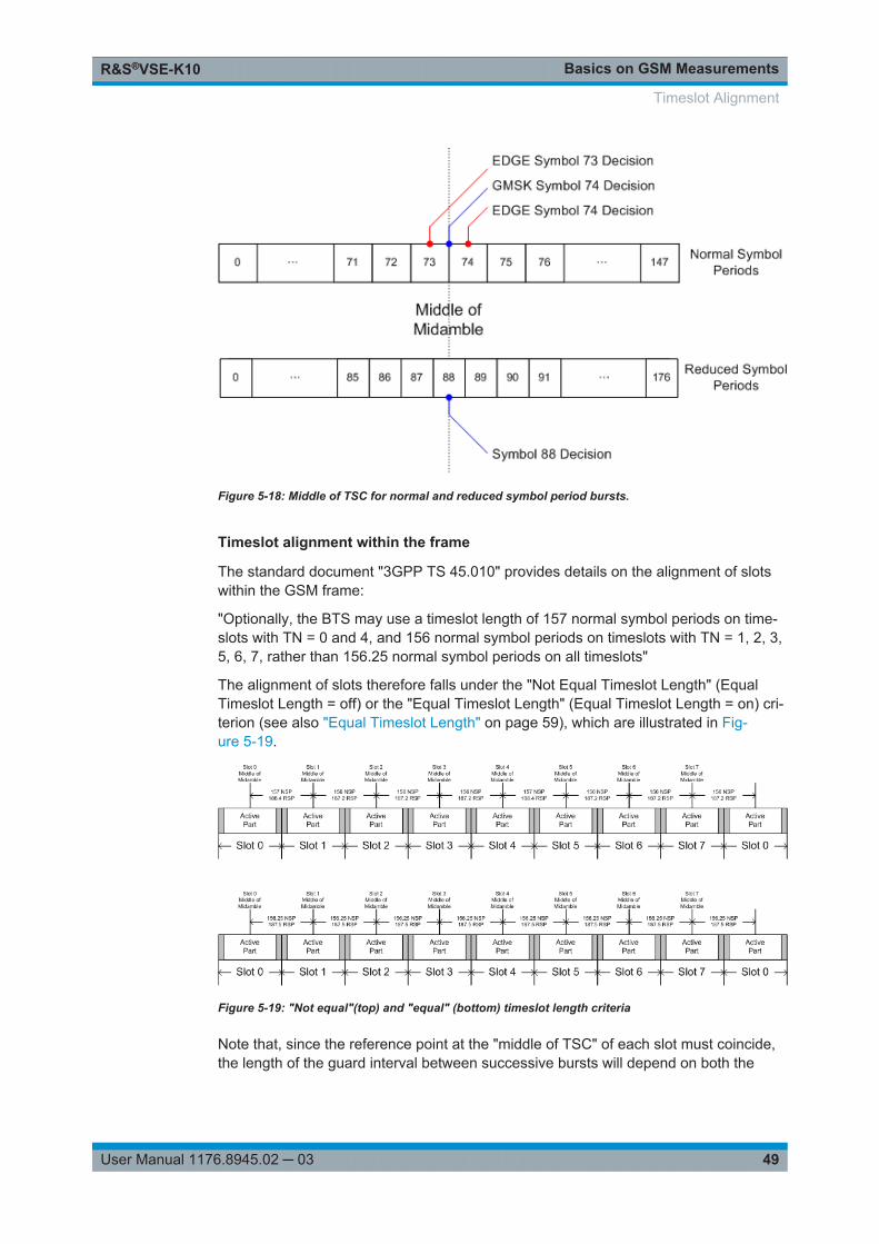
Basics on GSM MeasurementsR&S®VSE-K10
49User Manual 1176.8945.02 ─ 03
Figure 5-18: Middle of TSC for normal and reduced symbol period bursts.
Timeslot alignment within the frame
The standard document "3GPP TS 45.010" provides details on the alignment of slotswithin the GSM frame:
"Optionally, the BTS may use a timeslot length of 157 normal symbol periods on time-slots with TN = 0 and 4, and 156 normal symbol periods on timeslots with TN = 1, 2, 3,5, 6, 7, rather than 156.25 normal symbol periods on all timeslots"
The alignment of slots therefore falls under the "Not Equal Timeslot Length" (EqualTimeslot Length = off) or the "Equal Timeslot Length" (Equal Timeslot Length = on) cri-terion (see also "Equal Timeslot Length" on page 59), which are illustrated in Fig-ure 5-19.
Figure 5-19: "Not equal"(top) and "equal" (bottom) timeslot length criteria
Note that, since the reference point at the "middle of TSC" of each slot must coincide,the length of the guard interval between successive bursts will depend on both the
Timeslot Alignment
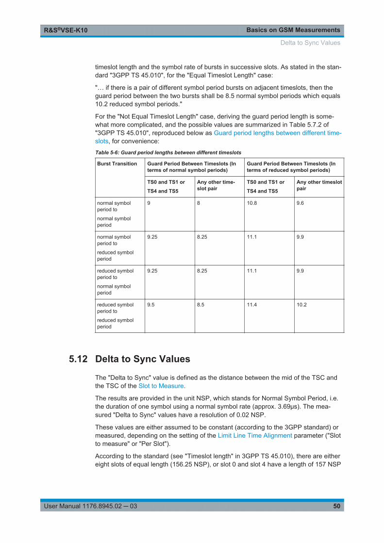
Basics on GSM MeasurementsR&S®VSE-K10
50User Manual 1176.8945.02 ─ 03
timeslot length and the symbol rate of bursts in successive slots. As stated in the stan-dard "3GPP TS 45.010", for the "Equal Timeslot Length" case:
"… if there is a pair of different symbol period bursts on adjacent timeslots, then theguard period between the two bursts shall be 8.5 normal symbol periods which equals10.2 reduced symbol periods."
For the "Not Equal Timeslot Length" case, deriving the guard period length is some-what more complicated, and the possible values are summarized in Table 5.7.2 of"3GPP TS 45.010", reproduced below as Guard period lengths between different time-slots, for convenience:
Table 5-6: Guard period lengths between different timeslots
Burst Transition Guard Period Between Timeslots (Interms of normal symbol periods)
Guard Period Between Timeslots (Interms of reduced symbol periods)
TS0 and TS1 or
TS4 and TS5
Any other time-slot pair
TS0 and TS1 or
TS4 and TS5
Any other timeslotpair
normal symbolperiod to
normal symbolperiod
9 8 10.8 9.6
normal symbolperiod to
reduced symbolperiod
9.25 8.25 11.1 9.9
reduced symbolperiod to
normal symbolperiod
9.25 8.25 11.1 9.9
reduced symbolperiod to
reduced symbolperiod
9.5 8.5 11.4 10.2
5.12 Delta to Sync Values
The "Delta to Sync" value is defined as the distance between the mid of the TSC andthe TSC of the Slot to Measure.
The results are provided in the unit NSP, which stands for Normal Symbol Period, i.e.the duration of one symbol using a normal symbol rate (approx. 3.69μs). The mea-sured "Delta to Sync" values have a resolution of 0.02 NSP.
These values are either assumed to be constant (according to the 3GPP standard) ormeasured, depending on the setting of the Limit Line Time Alignment parameter ("Slotto measure" or "Per Slot").
According to the standard (see "Timeslot length" in 3GPP TS 45.010), there are eithereight slots of equal length (156.25 NSP), or slot 0 and slot 4 have a length of 157 NSP
Delta to Sync Values
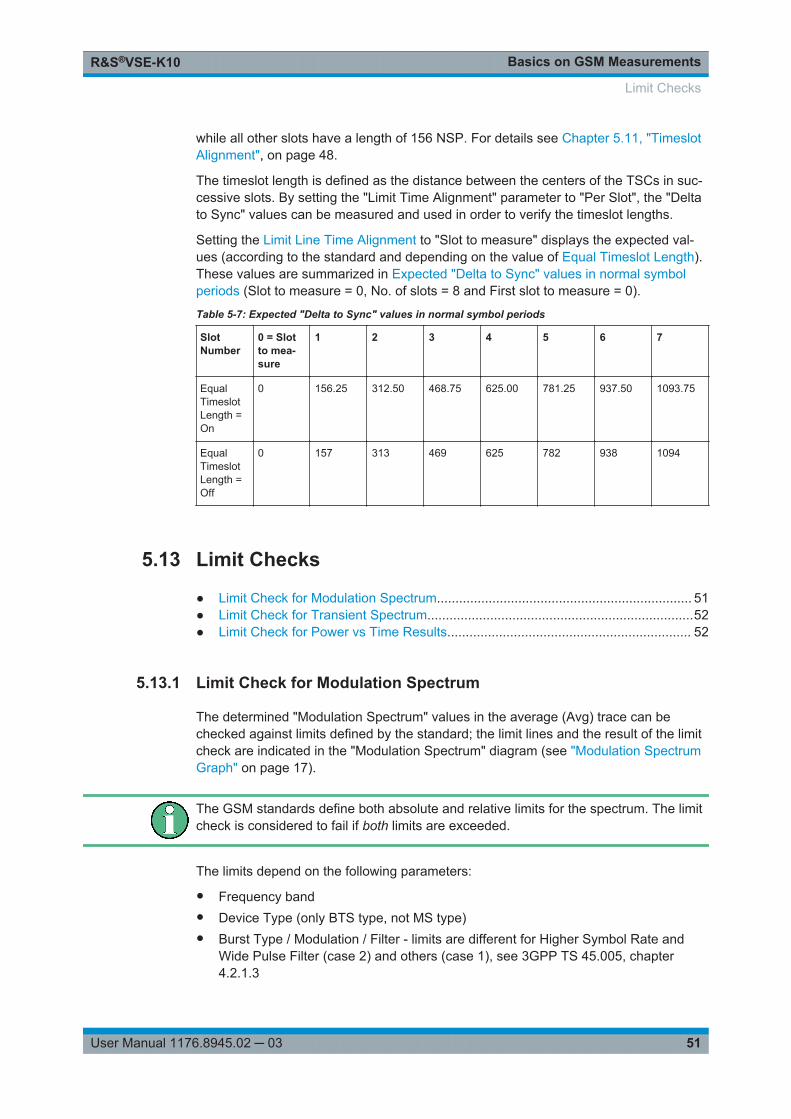
Basics on GSM MeasurementsR&S®VSE-K10
51User Manual 1176.8945.02 ─ 03
while all other slots have a length of 156 NSP. For details see Chapter 5.11, "TimeslotAlignment", on page 48.
The timeslot length is defined as the distance between the centers of the TSCs in suc-cessive slots. By setting the "Limit Time Alignment" parameter to "Per Slot", the "Deltato Sync" values can be measured and used in order to verify the timeslot lengths.
Setting the Limit Line Time Alignment to "Slot to measure" displays the expected val-ues (according to the standard and depending on the value of Equal Timeslot Length).These values are summarized in Expected "Delta to Sync" values in normal symbolperiods (Slot to measure = 0, No. of slots = 8 and First slot to measure = 0).
Table 5-7: Expected "Delta to Sync" values in normal symbol periods
SlotNumber
0 = Slotto mea-sure
1 2 3 4 5 6 7
EqualTimeslotLength =On
0 156.25 312.50 468.75 625.00 781.25 937.50 1093.75
EqualTimeslotLength =Off
0 157 313 469 625 782 938 1094
5.13 Limit Checks
● Limit Check for Modulation Spectrum..................................................................... 51● Limit Check for Transient Spectrum........................................................................52● Limit Check for Power vs Time Results.................................................................. 52
5.13.1 Limit Check for Modulation Spectrum
The determined "Modulation Spectrum" values in the average (Avg) trace can bechecked against limits defined by the standard; the limit lines and the result of the limitcheck are indicated in the "Modulation Spectrum" diagram (see "Modulation SpectrumGraph" on page 17).
The GSM standards define both absolute and relative limits for the spectrum. The limitcheck is considered to fail if both limits are exceeded.
The limits depend on the following parameters:
● Frequency band● Device Type (only BTS type, not MS type)● Burst Type / Modulation / Filter - limits are different for Higher Symbol Rate and
Wide Pulse Filter (case 2) and others (case 1), see 3GPP TS 45.005, chapter4.2.1.3
Limit Checks
Basics on GSM MeasurementsR&S®VSE-K10
52User Manual 1176.8945.02 ─ 03
● The measured reference power (30 kHz bandwidth)● The measured burst power (power level)● Number of active carriers for multicarrier BTS. The limit is relaxed by 10*log10(N)
dB for offset frequencies ≥1.8 MHz, see 3GPP TS 45.005 chapter 4.2.1.2
5.13.2 Limit Check for Transient Spectrum
The determined "Transient Spectrum Accuracy" values can be checked against limitsdefined by the standard; the limit lines and the result of the limit check are indicated inthe "Transient Spectrum" diagram (see "Transient Spectrum Graph" on page 24).
The limits depend on the following parameters:
● Graph: Limit check of maximum (Max) trace● Table: Limit check of absolute and relative scalar values● The limit masks are generated adaptively from the measured signal.● The limits depend on the following parameters:
– Frequency band (not for MS)– Burst Type / Modulation / Filter (not for MS)– The measured reference (slot) power
5.13.3 Limit Check for Power vs Time Results
The determined "Power vs Time" values can be checked against limits defined by thestandard; the limit lines and the result of the limit check are indicated in the "Power vsTime" diagram (see "PvT Full Burst" on page 22) and in the "Power vs Slot" table (see"Power vs Slot" on page 21).
The limits depend on the following parameters:
● The maximum (Max) trace is checked against the upper limit.● The minimum (Min) trace is checked against the lower limit.● The limit masks are generated adaptively from the measured signal according to
the following parameters:– Frequency band (special masks for PCS1900 and DCS1800 BTS with GMSK)– Burst type– Modulation– Filter– The reference burst power is measured and the "0 dB line" of the limit mask is
assigned to it.– For MS, the "-6 dB line" of the limit mask depends on the PCL. The PCL is
derived from the measured burst power.
Limit Checks
Basics on GSM MeasurementsR&S®VSE-K10
53User Manual 1176.8945.02 ─ 03
5.14 Impact of the "Statistic Count"
Generally, the "Statistic Count" defines how many measurements (or: analysis steps)are performed - equivalent to the "Sweep Count" in applications that perform sweeps.
In particular, the "Statistic Count" defines the number of frames to be included in statis-tical evaluations. For measurements on the Slot to Measure, the same slot is evaluatedin multiple frames, namely in the number specified by the "Statistic Count", for statisti-cal evaluations.
For Trigger to Sync measurements, where only one result is calculated per data acqui-sition, the "Statistic Count" determines how many values are considered for averaging.
Statistic count for Trigger to Sync vs other measurementsAs mentioned above, the "Statistic Count" for Trigger to Sync measurements refers tothe number of data acquisitions, whereas for all other measurements, the value refersto the number of frames. Since usually more than one frame is captured per dataacquisition, the number of data acquisitions required to obtain the required number ofresults (the "Statistic Count") may vary considerably. If both Trigger to Sync and otherresult types are active at the same time, the latter are finished first and the traces (inparticular the current measurement trace) remains unchanged until the Trigger to Syncmeasurement has also finished. The counter in the channel bar counts the "slower" ofthe two events, i.e. the number of measurements if a Trigger to Sync result display isactive.Tip: You can query the current value of the counter for both Trigger to Sync and othermeasurements in remote control, as well. See [SENSe:]SWEep:COUNt:TRGS:CURRent? on page 155.
Obviously, the "Statistic Count" has an impact on all results and values that are re-cal-culated after each measurement. The higher the count, the more values are taken intoconsideration, and the more likely the result of the calculation will converge to a stablevalue. On the other hand, the fewer measurements are considered, the higher the var-iance of the individual results, and the less reliable the calculation result will be.
For instance, if the "Statistic Count" is set to values smaller than 5, the measured refer-ence power for Modulation Spectrum Table (see "Modulation Spectrum Table"on page 18) and Transient Spectrum Table (see "Transient Spectrum Table"on page 25) measurements increases. This leads to a higher variance of the measuredrelative powers at the offset frequencies, and thus to a reduced measurementdynamic.
For the Power vs Time (see "PvT Full Burst" on page 22) and Power vs Slot (see"Power vs Slot" on page 21) measurements, a small "Statistic Count" increases thevariance of the measured slot powers. The slot power is required to calculate the PVTlimit lines.
Impact of the "Statistic Count"
Modulation Accuracy Measurement ConfigurationR&S®VSE-K10
54User Manual 1176.8945.02 ─ 03
6 Modulation Accuracy Measurement Config-urationGSM measurements require a special application on the R&S VSE.
Multiple access paths to functionalityThe easiest way to configure a measurement channel is via the "Overview" dialog box,which is displayed when you select the "Overview" icon from the main toolbar or the"Meas Setup" > "Overview" menu item.Alternatively, you can access the individual dialog boxes from the corresponding menuitems, or via tools in the toolbars, if available.In this documentation, only the most convenient method of accessing the dialog boxesis indicated - usually via the "Overview". For an overview of all available menu itemsand toolbar icons see Chapter A, "Annex: Reference", on page 258.
General R&S VSE functionsThe application-independent functions for general tasks on the R&S VSE are alsoavailable for GSM measurements and are described in the R&S VSE Base SoftwareUser Manual. In particular, this comprises the following functionality:● Controlling Instruments and Capturing I/Q Data● Data Management● General Software Preferences and Information
● Configuration Overview...........................................................................................54● Signal Description................................................................................................... 56● Input, Output and Frontend Settings.......................................................................65● Trigger Settings.......................................................................................................76● Data Acquisition...................................................................................................... 80● Demodulation..........................................................................................................82● Measurement Settings............................................................................................ 87● Adjusting Settings Automatically.............................................................................91● Result Configuration................................................................................................92
6.1 Configuration Overview
Access: "Meas Setup" > "Overview"
Throughout the measurement channel configuration, an overview of the most importantcurrently defined settings is provided in the "Overview".
Configuration Overview
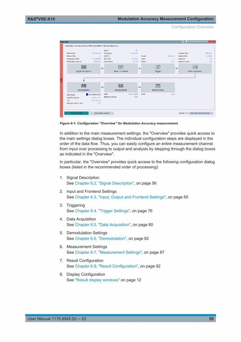
Modulation Accuracy Measurement ConfigurationR&S®VSE-K10
55User Manual 1176.8945.02 ─ 03
Figure 6-1: Configuration "Overview" for Modulation Accuracy measurement
In addition to the main measurement settings, the "Overview" provides quick access tothe main settings dialog boxes. The individual configuration steps are displayed in theorder of the data flow. Thus, you can easily configure an entire measurement channelfrom input over processing to output and analysis by stepping through the dialog boxesas indicated in the "Overview".
In particular, the "Overview" provides quick access to the following configuration dialogboxes (listed in the recommended order of processing):
1. Signal DescriptionSee Chapter 6.2, "Signal Description", on page 56
2. Input and Frontend SettingsSee Chapter 6.3, "Input, Output and Frontend Settings", on page 65
3. TriggeringSee Chapter 6.4, "Trigger Settings", on page 76
4. Data AcquisitionSee Chapter 6.5, "Data Acquisition", on page 80
5. Demodulation SettingsSee Chapter 6.6, "Demodulation", on page 82
6. Measurement SettingsSee Chapter 6.7, "Measurement Settings", on page 87
7. Result ConfigurationSee Chapter 6.9, "Result Configuration", on page 92
8. Display ConfigurationSee "Result display windows" on page 12
Configuration Overview

Modulation Accuracy Measurement ConfigurationR&S®VSE-K10
56User Manual 1176.8945.02 ─ 03
To configure settings
► Select any button to open the corresponding dialog box. The corresponding dialogbox is opened with the focus on the selected setting.
For step-by-step instructions on configuring GSM measurements, see Chapter 7, "Howto Perform Measurements in the GSM Application", on page 103.
Preset ChannelSelect the "Preset Channel" button in the lower left-hand corner of the "Overview" torestore all measurement settings in the current channel to their default values.
Remote command: SYSTem:PRESet:CHANnel[:EXEC] on page 119
Select MeasurementSelects a measurement to be performed.
Specifics forThe channel may contain several windows for different results. Thus, the settings indi-cated in the "Overview" and configured in the dialog boxes vary depending on theselected window.
Select an active window from the "Specifics for" selection list that is displayed in the"Overview" and in all window-specific configuration dialog boxes.
The "Overview" and dialog boxes are updated to indicate the settings for the selectedwindow.
6.2 Signal Description
Access: "Overview" > "Signal Description"
The signal description provides information on the expected input signal, which optimi-zes frame detection and measurement.
● Device Under Test Settings.................................................................................... 56● Frame......................................................................................................................58● Slot Settings............................................................................................................59● Carrier Settings....................................................................................................... 63
6.2.1 Device Under Test Settings
Access: "Overview" > "Signal Description" > "Device"
The type of device to be tested provides additional information on the signal to beexpected.
Signal Description
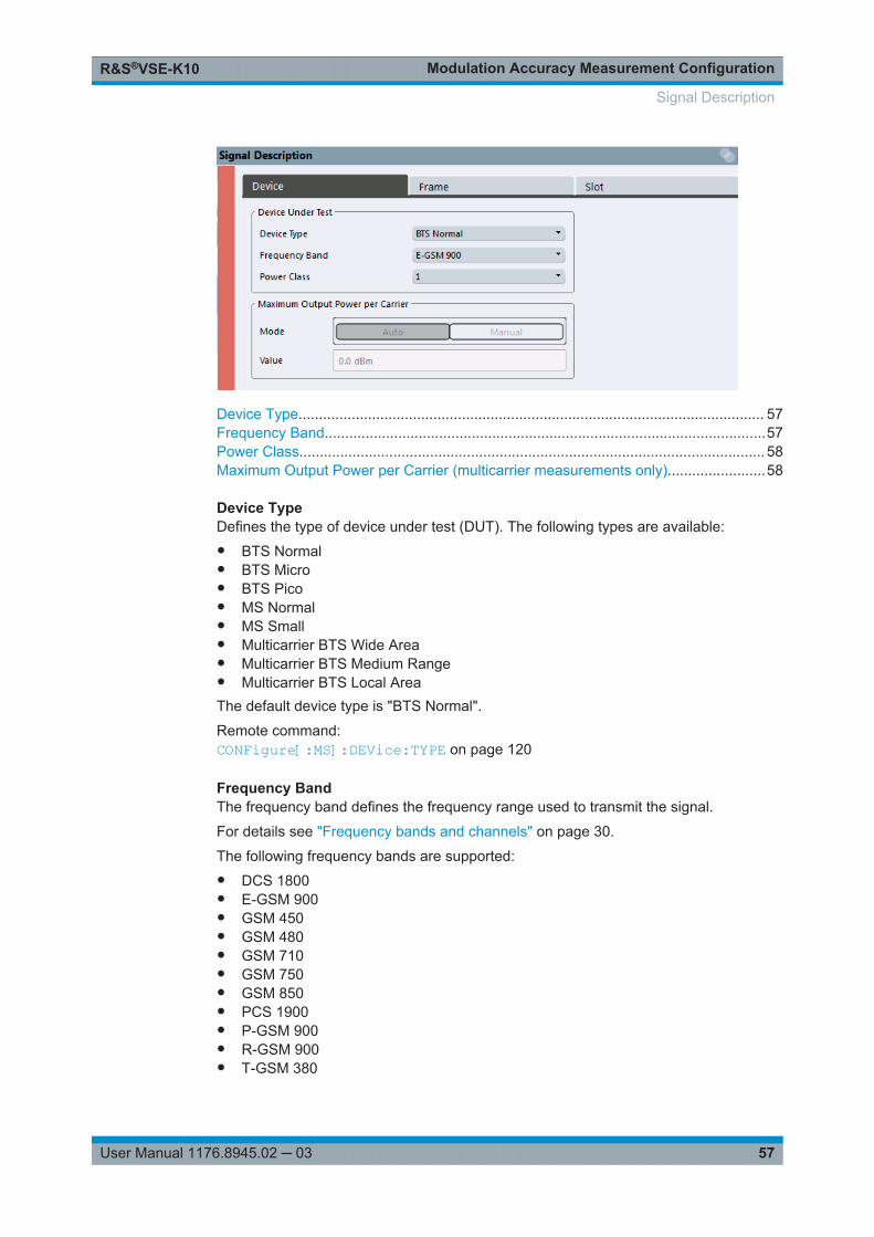
Modulation Accuracy Measurement ConfigurationR&S®VSE-K10
57User Manual 1176.8945.02 ─ 03
Device Type.................................................................................................................. 57Frequency Band............................................................................................................57Power Class.................................................................................................................. 58Maximum Output Power per Carrier (multicarrier measurements only)........................58
Device TypeDefines the type of device under test (DUT). The following types are available:● BTS Normal● BTS Micro● BTS Pico● MS Normal● MS Small● Multicarrier BTS Wide Area● Multicarrier BTS Medium Range● Multicarrier BTS Local AreaThe default device type is "BTS Normal".
Remote command: CONFigure[:MS]:DEVice:TYPE on page 120
Frequency BandThe frequency band defines the frequency range used to transmit the signal.
For details see "Frequency bands and channels" on page 30.
The following frequency bands are supported:● DCS 1800● E-GSM 900● GSM 450● GSM 480● GSM 710● GSM 750● GSM 850● PCS 1900● P-GSM 900● R-GSM 900● T-GSM 380
Signal Description
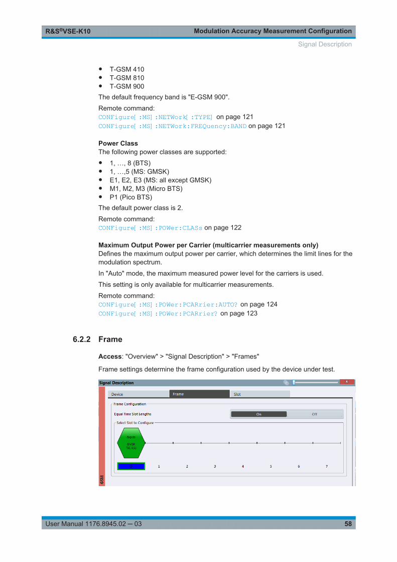
Modulation Accuracy Measurement ConfigurationR&S®VSE-K10
58User Manual 1176.8945.02 ─ 03
● T-GSM 410● T-GSM 810● T-GSM 900The default frequency band is "E-GSM 900".
Remote command: CONFigure[:MS]:NETWork[:TYPE] on page 121CONFigure[:MS]:NETWork:FREQuency:BAND on page 121
Power ClassThe following power classes are supported:● 1, …, 8 (BTS)● 1, …,5 (MS: GMSK)● E1, E2, E3 (MS: all except GMSK)● M1, M2, M3 (Micro BTS)● P1 (Pico BTS)The default power class is 2.
Remote command: CONFigure[:MS]:POWer:CLASs on page 122
Maximum Output Power per Carrier (multicarrier measurements only)Defines the maximum output power per carrier, which determines the limit lines for themodulation spectrum.
In "Auto" mode, the maximum measured power level for the carriers is used.
This setting is only available for multicarrier measurements.
Remote command: CONFigure[:MS]:POWer:PCARrier:AUTO? on page 124CONFigure[:MS]:POWer:PCARrier? on page 123
6.2.2 Frame
Access: "Overview" > "Signal Description" > "Frames"
Frame settings determine the frame configuration used by the device under test.
Signal Description
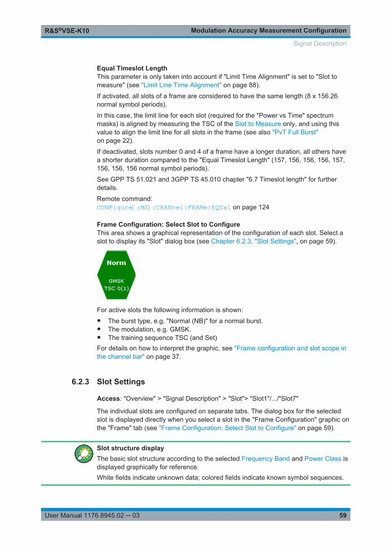
Modulation Accuracy Measurement ConfigurationR&S®VSE-K10
59User Manual 1176.8945.02 ─ 03
Equal Timeslot LengthThis parameter is only taken into account if "Limit Time Alignment" is set to "Slot tomeasure" (see "Limit Line Time Alignment" on page 88).
If activated, all slots of a frame are considered to have the same length (8 x 156.26normal symbol periods).
In this case, the limit line for each slot (required for the "Power vs Time" spectrummasks) is aligned by measuring the TSC of the Slot to Measure only, and using thisvalue to align the limit line for all slots in the frame (see also "PvT Full Burst"on page 22).
If deactivated, slots number 0 and 4 of a frame have a longer duration, all others havea shorter duration compared to the "Equal Timeslot Length" (157, 156, 156, 156, 157,156, 156, 156 normal symbol periods).
See GPP TS 51.021 and 3GPP TS 45.010 chapter "6.7 Timeslot length" for furtherdetails.
Remote command: CONFigure[:MS]:CHANnel:FRAMe:EQUal on page 124
Frame Configuration: Select Slot to ConfigureThis area shows a graphical representation of the configuration of each slot. Select aslot to display its "Slot" dialog box (see Chapter 6.2.3, "Slot Settings", on page 59).
For active slots the following information is shown:● The burst type, e.g. "Normal (NB)" for a normal burst.● The modulation, e.g. GMSK.● The training sequence TSC (and Set)For details on how to interpret the graphic, see "Frame configuration and slot scope inthe channel bar" on page 37.
6.2.3 Slot Settings
Access: "Overview" > "Signal Description" > "Slot"> "Slot1"/.../"Slot7"
The individual slots are configured on separate tabs. The dialog box for the selectedslot is displayed directly when you select a slot in the "Frame Configuration" graphic onthe "Frame" tab (see "Frame Configuration: Select Slot to Configure" on page 59).
Slot structure displayThe basic slot structure according to the selected Frequency Band and Power Class isdisplayed graphically for reference.White fields indicate unknown data; colored fields indicate known symbol sequences.
Signal Description
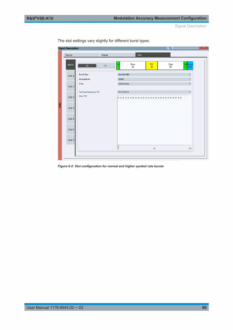
Modulation Accuracy Measurement ConfigurationR&S®VSE-K10
60User Manual 1176.8945.02 ─ 03
The slot settings vary slightly for different burst types.
Figure 6-2: Slot configuration for normal and higher symbol rate bursts
Signal Description
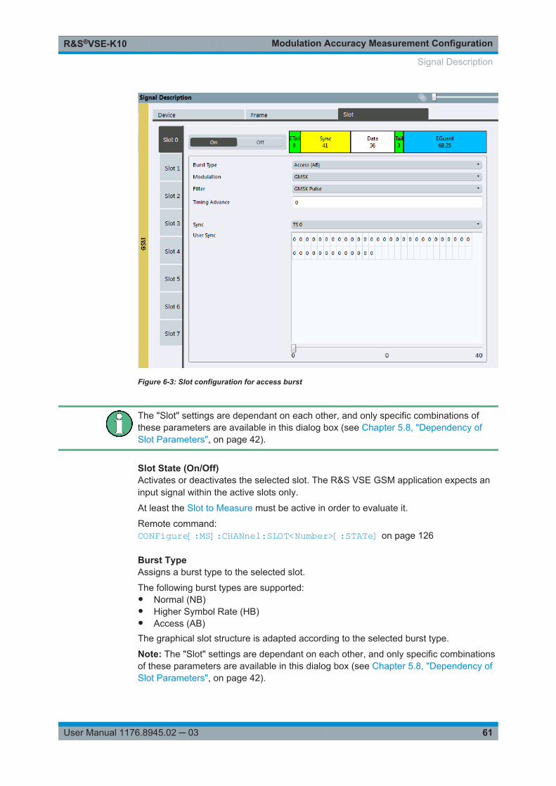
Modulation Accuracy Measurement ConfigurationR&S®VSE-K10
61User Manual 1176.8945.02 ─ 03
Figure 6-3: Slot configuration for access burst
The "Slot" settings are dependant on each other, and only specific combinations ofthese parameters are available in this dialog box (see Chapter 5.8, "Dependency ofSlot Parameters", on page 42).
Slot State (On/Off)Activates or deactivates the selected slot. The R&S VSE GSM application expects aninput signal within the active slots only.
At least the Slot to Measure must be active in order to evaluate it.
Remote command: CONFigure[:MS]:CHANnel:SLOT<Number>[:STATe] on page 126
Burst TypeAssigns a burst type to the selected slot.
The following burst types are supported:● Normal (NB)● Higher Symbol Rate (HB)● Access (AB)The graphical slot structure is adapted according to the selected burst type.
Note: The "Slot" settings are dependant on each other, and only specific combinationsof these parameters are available in this dialog box (see Chapter 5.8, "Dependency ofSlot Parameters", on page 42).
Signal Description
Modulation Accuracy Measurement ConfigurationR&S®VSE-K10
62User Manual 1176.8945.02 ─ 03
Remote command: CONFigure[:MS]:CHANnel:SLOT<Number>:TYPE on page 131
ModulationDefines the modulation used in the slot.
The possible modulations depend on the set burst type (see Chapter 5.8, "Dependencyof Slot Parameters", on page 42).
The graphical slot structure is adapted according to the selected modulation.
Remote command: CONFigure[:MS]:CHANnel:SLOT<Number>:MTYPe on page 126
SCPIRThis parameter is only available for AQPSK modulation.
It specifies the Subchannel Power Imbalance Ratio (SCPIR). The value of SCPIRaffects the shape of the AQPSK constellation (see Chapter 5.4, "AQPSK Modulation",on page 34). For an SCPIR of 0 dB the constellation is square (as in "normal" QPSK),while for other values of SCPIR the constellation becomes rectangular.
Remote command: CONFigure[:MS]:CHANnel:SLOT<s>:SCPir on page 127
FilterSpecifies the pulse shape of the modulator on the DUT and thus the measurement fil-ter in the R&S VSE GSM application.
(For details see Chapter 5.7.3, "Measurement Filter", on page 41).
The following filter types are supported for normal and higher symbol rate bursts:● GMSK Pulse● Linearized GMSK Pulse● Narrow Pulse● Wide PulseFor access bursts, only a GMSK Pulse filter is supported.
Remote command: CONFigure[:MS]:CHANnel:SLOT<Number>:FILTer on page 125
Timing Advance (Access Burst only)Specifies the position of an access burst within a single slot as an offset in symbolsfrom the slot start.
Remote command: CONFigure[:MS]:CHANnel:SLOT<Number>:TADVance on page 128
Training Sequence TSC/Sync(Note: for Access bursts, this setting is labeled "Sync", but the functionality is thesame.)
The "Training Sequence TSC" or "Sync" values are known symbol sequences used tosynchronize the measured signal with the expected input signal in a single slot.
The available values depend on the modulation as indicated in the table below.
Signal Description
Modulation Accuracy Measurement ConfigurationR&S®VSE-K10
63User Manual 1176.8945.02 ─ 03
For user-defined TSCs, select "User" and define the training sequence in the UserTSC/User Sync table.
For more information on TSCs see "Training sequences (TSCs)" on page 33.
Remote command: CONFigure[:MS]:CHANnel:SLOT<s>:TSC on page 129AQPSK:CONFigure[:MS]:CHANnel:SLOT<s>:SUBChannel<ch>:TSC on page 128
User TSC/User Sync(Note: for Access bursts, this setting is labeled "User Sync", but the functionality is thesame.)
Defines the bits of the user-defined TSC or Sync. The number of bits depend on theburst type and the modulation and is indicated in Table 6-1.
For AQPSK modulation, the training sequence is defined for each subchannel, seeChapter 5.4, "AQPSK Modulation", on page 34.
Note:As the "User TSC" table in the dialog box only displays 25 bits at a time, a scrollbarbeneath the table allows you to display the remaining bits. The currently selected bitnumber is indicated in the center of the scrollbar.Table 6-1: Number of TSC bits depending on burst type and modulation
Burst Type Modulation Number of Bits
Normal GMSK 26
Normal 8PSK 78
Normal 16QAM 104
Normal 32QAM 130
Higher Symbol Rate QPSK 62
Higher Symbol Rate 16QAM 124
Higher Symbol Rate 32QAM 155
Access GMSK 41
Remote command: CONFigure[:MS]:CHANnel:SLOT<s>:TSC:USER on page 130AQPSK:CONFigure[:MS]:CHANnel:SLOT<s>:SUBChannel<ch>:TSC:USER on page 127
6.2.4 Carrier Settings
Access: "Overview" > "Signal Description" > "Carriers"
The "Carrier" settings define whether the expected signal contains a single or multiplecarriers. Multiple carriers can only be defined if a multicarrier Device Type is selected(see Chapter 6.2.1, "Device Under Test Settings", on page 56.
Signal Description
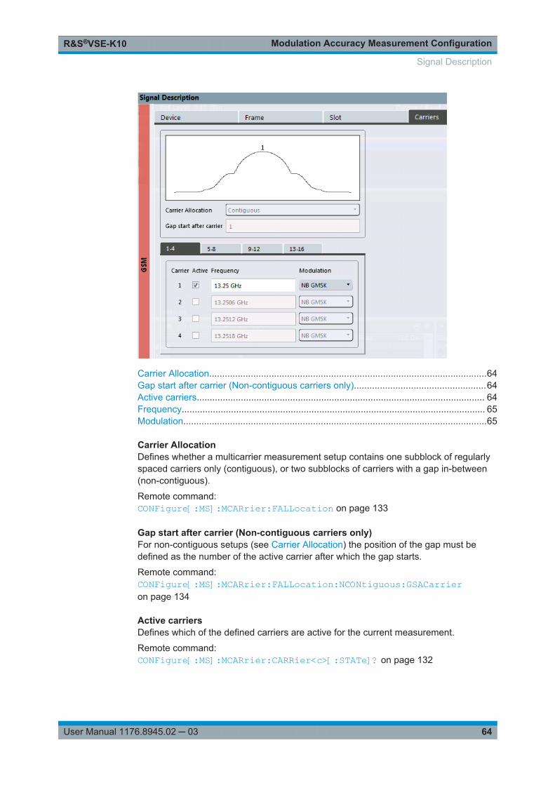
Modulation Accuracy Measurement ConfigurationR&S®VSE-K10
64User Manual 1176.8945.02 ─ 03
Carrier Allocation...........................................................................................................64Gap start after carrier (Non-contiguous carriers only)...................................................64Active carriers............................................................................................................... 64Frequency..................................................................................................................... 65Modulation.....................................................................................................................65
Carrier AllocationDefines whether a multicarrier measurement setup contains one subblock of regularlyspaced carriers only (contiguous), or two subblocks of carriers with a gap in-between(non-contiguous).
Remote command: CONFigure[:MS]:MCARrier:FALLocation on page 133
Gap start after carrier (Non-contiguous carriers only)For non-contiguous setups (see Carrier Allocation) the position of the gap must bedefined as the number of the active carrier after which the gap starts.
Remote command: CONFigure[:MS]:MCARrier:FALLocation:NCONtiguous:GSACarrieron page 134
Active carriersDefines which of the defined carriers are active for the current measurement.
Remote command: CONFigure[:MS]:MCARrier:CARRier<c>[:STATe]? on page 132
Signal Description
Modulation Accuracy Measurement ConfigurationR&S®VSE-K10
65User Manual 1176.8945.02 ─ 03
FrequencyDefines the absolute frequency of each (active) carrier.
Remote command: CONFigure[:MS]:MCARrier:CARRier<c>:FREQuency on page 132
ModulationDefines the burst type, modulation and pulse shape filter of each (active) carrier.
For possible combinations see Chapter 5.8, "Dependency of Slot Parameters",on page 42.
Note: This setting determines the appropriate limits from the 3GPP standard.
Remote command: CONFigure[:MS]:MCARrier:CARRier<c>:MTYPe on page 132
6.3 Input, Output and Frontend Settings
Access: "Overview" > "Input/Frontend"
The R&S VSE can evaluate signals from different input sources and provide varioustypes of output (such as noise or trigger signals).
Output settings are described in the R&S VSE Base Software User Manual.
● Input Source Settings..............................................................................................65● Frequency Settings................................................................................................. 71● Amplitude Settings.................................................................................................. 74
6.3.1 Input Source Settings
Access: "Overview" > "Input/Frontend" > "Input Source"
Or: "Input & Output" > "Input Source"
The R&S VSE can control the input sources of the connected instruments.
● Radio Frequency Input............................................................................................65● I/Q File Input............................................................................................................71
6.3.1.1 Radio Frequency Input
Access: "Overview" > "Input/Frontend" > "Input Source" > "Radio Frequency"
Or: "Input & Output" > "Input Source" > "Radio Frequency"
The default input source for the connected instrument is "Radio Frequency". Depend-ing on the connected instrument, different input parameters are available.
Input, Output and Frontend Settings
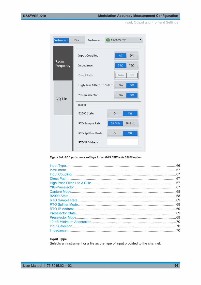
Modulation Accuracy Measurement ConfigurationR&S®VSE-K10
66User Manual 1176.8945.02 ─ 03
Figure 6-4: RF input source settings for an R&S FSW with B2000 option
Input Type..................................................................................................................... 66Instrument..................................................................................................................... 67Input Coupling .............................................................................................................. 67Direct Path ................................................................................................................... 67High Pass Filter 1 to 3 GHz ..........................................................................................67YIG-Preselector ............................................................................................................67Capture Mode............................................................................................................... 68B2000 State.................................................................................................................. 68RTO Sample Rate.........................................................................................................69RTO Splitter Mode........................................................................................................ 69RTO IP Address............................................................................................................ 69Preselector State...........................................................................................................69Preselector Mode.......................................................................................................... 6910 dB Minimum Attenuation.......................................................................................... 70Input Selection.............................................................................................................. 70Impedance ................................................................................................................... 70
Input TypeSelects an instrument or a file as the type of input provided to the channel.
Input, Output and Frontend Settings
Modulation Accuracy Measurement ConfigurationR&S®VSE-K10
67User Manual 1176.8945.02 ─ 03
Remote command: INSTrument:BLOCk:CHANnel[:SETTings]:SOURce on page 138INPut:SELect on page 137
InstrumentSpecifies a configured instrument to be used for input.
Input CouplingThe RF input of the connected instrument can be coupled by alternating current (AC)or direct current (DC).
AC coupling blocks any DC voltage from the input signal. This is the default setting toprevent damage to the instrument. Very low frequencies in the input signal may be dis-torted.
However, some specifications require DC coupling. In this case, you must protect theinstrument from damaging DC input voltages manually. For details, refer to the datasheet.
Remote command: INPut:COUPling on page 135
Direct PathEnables or disables the use of the direct path for small frequencies.
In spectrum analyzers, passive analog mixers are used for the first conversion of theinput signal. In such mixers, the LO signal is coupled into the IF path due to its limitedisolation. The coupled LO signal becomes visible at the RF frequency 0 Hz. This effectis referred to as LO feedthrough.
To avoid the LO feedthrough the spectrum analyzer provides an alternative signal pathto the A/D converter, referred to as the direct path. By default, the direct path isselected automatically for RF frequencies close to zero. However, this behavior can bedeactivated. If "Direct Path" is set to "Off" , the spectrum analyzer always uses the ana-log mixer path.
"Auto" (Default) The direct path is used automatically for frequencies closeto zero.
"Off" The analog mixer path is always used.
Remote command: INPut:DPATh on page 135
High Pass Filter 1 to 3 GHzActivates an additional internal high-pass filter for RF input signals from 1 GHz to3 GHz. This filter is used to remove the harmonics of the analyzer to measure the har-monics for a DUT, for example.
This function may require an additional hardware option on the connected instrument.
Remote command: INPut:FILTer:HPASs[:STATe] on page 135
YIG-PreselectorActivates or deactivates the YIG-preselector, if available on the connected instrument.
Input, Output and Frontend Settings
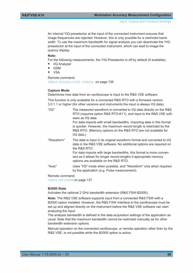
Modulation Accuracy Measurement ConfigurationR&S®VSE-K10
68User Manual 1176.8945.02 ─ 03
An internal YIG-preselector at the input of the connected instrument ensures thatimage frequencies are rejected. However, this is only possible for a restricted band-width. To use the maximum bandwidth for signal analysis you can deactivate the YIG-preselector at the input of the connected instrument, which can lead to image-fre-quency display.
Note:For the following measurements, the YIG-Preselector is off by default (if available).● I/Q Analyzer● GSM● VSA
Remote command: INPut:FILTer:YIG[:STATe] on page 136
Capture ModeDetermines how data from an oscilloscope is input to the R&S VSE software.
This function is only available for a connected R&S RTO with a firmware version3.0.1.1 or higher (for other versions and instruments the input is always I/Q data).
"I/Q" The measured waveform is converted to I/Q data directly on the R&SRTO (requires option R&S RTO-K11), and input to the R&S VSE soft-ware as I/Q data.For data imports with small bandwidths, importing data in this formatis quicker. However, the maximum record length is restricted by theR&S RTO. (Memory options on the R&S RTO are not available forI/Q data.)
"Waveform" The data is input in its original waveform format and converted to I/Qdata in the R&S VSE software. No additional options are required onthe R&S RTO.For data imports with large bandwidths, this format is more conven-ient as it allows for longer record lengths if appropriate memoryoptions are available on the R&S RTO.
"Auto" Uses "I/Q" mode when possible, and "Waveform" only when requiredby the application (e.g. Pulse measurement).
Remote command: INPut:RF:CAPM on page 137
B2000 StateActivates the optional 2 GHz bandwidth extension (R&S FSW-B2000).
Note: The R&S VSE software supports input from a connected R&S FSW with aB2000 option installed. However, the R&S FSW interface to the oscilloscope must beset up and aligned directly on the instrument before the R&S VSE software can startanalyzing the input.The analysis bandwidth is defined in the data acquisition settings of the application asusual. Note that the maximum bandwidth cannot be restricted manually as for otherbandwidth extension options.Manual operation on the connected oscilloscope, or remote operation other than by theR&S VSE, is not possible while the B2000 option is active.
Input, Output and Frontend Settings
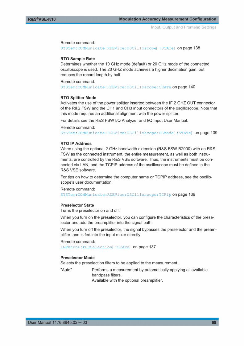
Modulation Accuracy Measurement ConfigurationR&S®VSE-K10
69User Manual 1176.8945.02 ─ 03
Remote command: SYSTem:COMMunicate:RDEVice:OSCilloscope[:STATe] on page 138
RTO Sample RateDetermines whether the 10 GHz mode (default) or 20 GHz mode of the connectedoscilloscope is used. The 20 GHZ mode achieves a higher decimation gain, butreduces the record length by half.
Remote command: SYSTem:COMMunicate:RDEVice:OSCilloscope:SRATe on page 140
RTO Splitter ModeActivates the use of the power splitter inserted between the IF 2 GHZ OUT connectorof the R&S FSW and the CH1 and CH3 input connectors of the oscilloscope. Note thatthis mode requires an additional alignment with the power splitter.
For details see the R&S FSW I/Q Analyzer and I/Q Input User Manual.
Remote command: SYSTem:COMMunicate:RDEVice:OSCilloscope:PSMode[:STATe] on page 139
RTO IP AddressWhen using the optional 2 GHz bandwidth extension (R&S FSW-B2000) with an R&SFSW as the connected instrument, the entire measurement, as well as both instru-ments, are controlled by the R&S VSE software. Thus, the instruments must be con-nected via LAN, and the TCPIP address of the oscilloscope must be defined in theR&S VSE software.
For tips on how to determine the computer name or TCPIP address, see the oscillo-scope's user documentation.
Remote command: SYSTem:COMMunicate:RDEVice:OSCilloscope:TCPip on page 139
Preselector StateTurns the preselector on and off.
When you turn on the preselector, you can configure the characteristics of the prese-lector and add the preamplifier into the signal path.
When you turn off the preselector, the signal bypasses the preselector and the pream-plifier, and is fed into the input mixer directly.
Remote command: INPut<n>:PRESelection[:STATe] on page 137
Preselector ModeSelects the preselection filters to be applied to the measurement.
"Auto" Performs a measurement by automatically applying all availablebandpass filters.Available with the optional preamplifier.
Input, Output and Frontend Settings
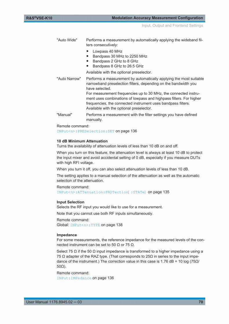
Modulation Accuracy Measurement ConfigurationR&S®VSE-K10
70User Manual 1176.8945.02 ─ 03
"Auto Wide" Performs a measurement by automatically applying the wideband fil-ters consecutively:● Lowpass 40 MHz● Bandpass 30 MHz to 2250 MHz● Bandpass 2 GHz to 8 GHz● Bandpass 8 GHz to 26.5 GHzAvailable with the optional preselector.
"Auto Narrow" Performs a measurement by automatically applying the most suitablenarrowband preselection filters, depending on the bandwidth youhave selected.For measurement frequencies up to 30 MHz, the connected instru-ment uses combinations of lowpass and highpass filters. For higherfrequencies, the connected instrument uses bandpass filters.Available with the optional preselector.
"Manual" Performs a measurement with the filter settings you have definedmanually.
Remote command: INPut<n>:PRESelection:SET on page 136
10 dB Minimum AttenuationTurns the availability of attenuation levels of less than 10 dB on and off.
When you turn on this feature, the attenuation level is always at least 10 dB to protectthe input mixer and avoid accidental setting of 0 dB, especially if you measure DUTswith high RFI voltage.
When you turn it off, you can also select attenuation levels of less than 10 dB.
The setting applies to a manual selection of the attenuation as well as the automaticselection of the attenuation.
Remote command: INPut<n>:ATTenuation:PROTection[:STATe] on page 135
Input SelectionSelects the RF input you would like to use for a measurement.
Note that you cannot use both RF inputs simultaneously.
Remote command: Global: INPut<n>:TYPE on page 138
ImpedanceFor some measurements, the reference impedance for the measured levels of the con-nected instrument can be set to 50 Ω or 75 Ω.
Select 75 Ω if the 50 Ω input impedance is transformed to a higher impedance using a75 Ω adapter of the RAZ type. (That corresponds to 25Ω in series to the input impe-dance of the instrument.) The correction value in this case is 1.76 dB = 10 log (75Ω/50Ω).
Remote command: INPut:IMPedance on page 136
Input, Output and Frontend Settings
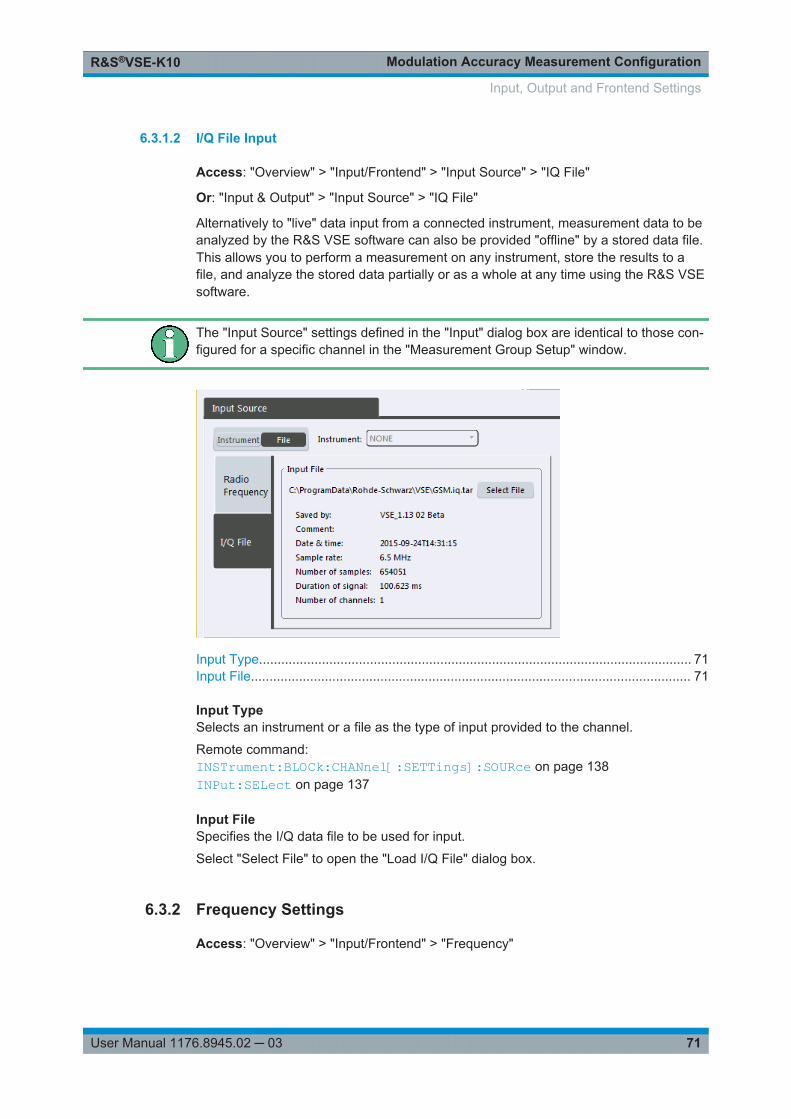
Modulation Accuracy Measurement ConfigurationR&S®VSE-K10
71User Manual 1176.8945.02 ─ 03
6.3.1.2 I/Q File Input
Access: "Overview" > "Input/Frontend" > "Input Source" > "IQ File"
Or: "Input & Output" > "Input Source" > "IQ File"
Alternatively to "live" data input from a connected instrument, measurement data to beanalyzed by the R&S VSE software can also be provided "offline" by a stored data file.This allows you to perform a measurement on any instrument, store the results to afile, and analyze the stored data partially or as a whole at any time using the R&S VSEsoftware.
The "Input Source" settings defined in the "Input" dialog box are identical to those con-figured for a specific channel in the "Measurement Group Setup" window.
Input Type..................................................................................................................... 71Input File....................................................................................................................... 71
Input TypeSelects an instrument or a file as the type of input provided to the channel.
Remote command: INSTrument:BLOCk:CHANnel[:SETTings]:SOURce on page 138INPut:SELect on page 137
Input FileSpecifies the I/Q data file to be used for input.
Select "Select File" to open the "Load I/Q File" dialog box.
6.3.2 Frequency Settings
Access: "Overview" > "Input/Frontend" > "Frequency"
Input, Output and Frontend Settings
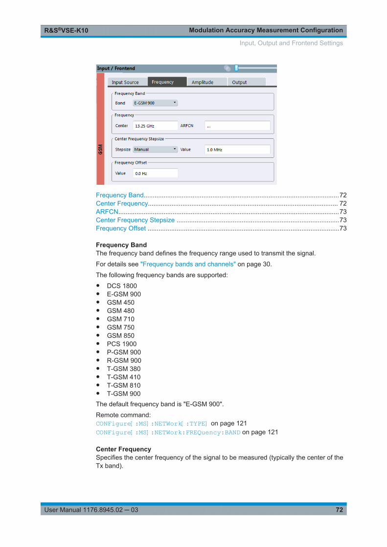
Modulation Accuracy Measurement ConfigurationR&S®VSE-K10
72User Manual 1176.8945.02 ─ 03
Frequency Band............................................................................................................72Center Frequency......................................................................................................... 72ARFCN..........................................................................................................................73Center Frequency Stepsize ..........................................................................................73Frequency Offset ..........................................................................................................73
Frequency BandThe frequency band defines the frequency range used to transmit the signal.
For details see "Frequency bands and channels" on page 30.
The following frequency bands are supported:● DCS 1800● E-GSM 900● GSM 450● GSM 480● GSM 710● GSM 750● GSM 850● PCS 1900● P-GSM 900● R-GSM 900● T-GSM 380● T-GSM 410● T-GSM 810● T-GSM 900The default frequency band is "E-GSM 900".
Remote command: CONFigure[:MS]:NETWork[:TYPE] on page 121CONFigure[:MS]:NETWork:FREQuency:BAND on page 121
Center FrequencySpecifies the center frequency of the signal to be measured (typically the center of theTx band).
Input, Output and Frontend Settings
Modulation Accuracy Measurement ConfigurationR&S®VSE-K10
73User Manual 1176.8945.02 ─ 03
If the frequency is modified, the "ARFCN" is updated accordingly (for I/Q measure-ments, see ARFCN).
Remote command: [SENSe:]FREQuency:CENTer on page 141
ARFCNDefines the Absolute Radio Frequency Channel Number (ARFCN). The "Center Fre-quency" on page 72 is adapted accordingly.
Possible values are in the range from 0 to 1023; however, some values may not beallowed depending on the selected Frequency Band.
Remote command: CONFigure[:MS]:ARFCn on page 141
Center Frequency StepsizeDefines the step size by which the center frequency is increased or decreased usingthe arrow keys.
When you use the mouse wheel, the center frequency changes in steps of only 1/10 ofthe span.
The step size can be coupled to another value or it can be manually set to a fixedvalue.
"X * Span" Sets the step size for the center frequency to a defined factor of thespan. The "X-Factor" defines the percentage of the span.Values between 1 % and 100 % in steps of 1 % are allowed. Thedefault setting is 10 %.
"= Center" Sets the step size to the value of the center frequency. The usedvalue is indicated in the "Value" field.
"Manual" Defines a fixed step size for the center frequency. Enter the step sizein the "Value" field.
Remote command: [SENSe:]FREQuency:CENTer:STEP on page 142
Frequency OffsetShifts the displayed frequency range along the x-axis by the defined offset.
This parameter has no effect on the instrument's hardware, or on the captured data oron data processing. It is simply a manipulation of the final results in which absolute fre-quency values are displayed. Thus, the x-axis of a spectrum display is shifted by aconstant offset if it shows absolute frequencies, but not if it shows frequencies relativeto the signal's center frequency.
A frequency offset can be used to correct the display of a signal that is slightly distortedby the measurement setup, for example.
The allowed values range from -100 GHz to 100 GHz. The default setting is 0 Hz.
Remote command: [SENSe:]FREQuency:OFFSet on page 143
Input, Output and Frontend Settings
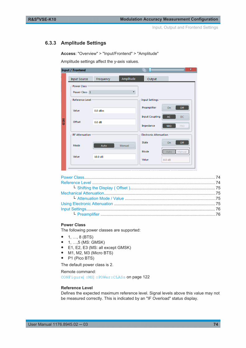
Modulation Accuracy Measurement ConfigurationR&S®VSE-K10
74User Manual 1176.8945.02 ─ 03
6.3.3 Amplitude Settings
Access: "Overview" > "Input/Frontend" > "Amplitude"
Amplitude settings affect the y-axis values.
Power Class.................................................................................................................. 74Reference Level ........................................................................................................... 74
└ Shifting the Display ( Offset ).......................................................................... 75Mechanical Attenuation.................................................................................................75
└ Attenuation Mode / Value ...............................................................................75Using Electronic Attenuation ........................................................................................ 75Input Settings................................................................................................................ 76
└ Preamplifier ....................................................................................................76
Power ClassThe following power classes are supported:● 1, …, 8 (BTS)● 1, …,5 (MS: GMSK)● E1, E2, E3 (MS: all except GMSK)● M1, M2, M3 (Micro BTS)● P1 (Pico BTS)The default power class is 2.
Remote command: CONFigure[:MS]:POWer:CLASs on page 122
Reference LevelDefines the expected maximum reference level. Signal levels above this value may notbe measured correctly. This is indicated by an "IF Overload" status display.
Input, Output and Frontend Settings
Modulation Accuracy Measurement ConfigurationR&S®VSE-K10
75User Manual 1176.8945.02 ─ 03
The reference level can also be used to scale power diagrams; the reference level isthen used as the maximum on the y-axis.
Since the hardware of the connected instrument is adapted according to this value, it isrecommended that you set the reference level close above the expected maximum sig-nal level. Thus you ensure an optimum measurement (no compression, good signal-to-noise ratio).
Remote command: DISPlay[:WINDow<n>]:TRACe<t>:Y[:SCALe]:RLEVel on page 144
Shifting the Display ( Offset ) ← Reference LevelDefines an arithmetic level offset. This offset is added to the measured level. In someresult displays, the scaling of the y-axis is changed accordingly.
Define an offset if the signal is attenuated or amplified before it is fed into the R&S VSEso the application shows correct power results. All displayed power level results areshifted by this value.
The setting range is ±200 dB in 0.01 dB steps.
Note, however, that the internal reference level (used to adjust the hardware settings tothe expected signal) ignores any "Reference Level Offset" . Thus, it is important tokeep in mind the actual power level the R&S VSE must handle. Do not rely on the dis-played reference level (internal reference level = displayed reference level - offset).
Remote command: DISPlay[:WINDow<n>]:TRACe<t>:Y[:SCALe]:RLEVel:OFFSet on page 144
Mechanical AttenuationDefines the mechanical attenuation for RF input.
Attenuation Mode / Value ← Mechanical AttenuationThe RF attenuation can be set automatically as a function of the selected referencelevel (Auto mode). This ensures that no overload occurs at the RF INPUT connectorfor the current reference level. It is the default setting.
In "Manual" mode, you can set the RF attenuation in 1 dB steps (down to 0 dB). Otherentries are rounded to the next integer value. The range is specified in the data sheet.If the defined reference level cannot be set for the defined RF attenuation, the refer-ence level is adjusted accordingly and the warning "limit reached" is displayed.
NOTICE! Risk of hardware damage due to high power levels. When decreasing theattenuation manually, ensure that the power level does not exceed the maximum levelallowed at the RF input, as an overload may lead to hardware damage.
Remote command: INPut:ATTenuation on page 145INPut:ATTenuation:AUTO on page 145
Using Electronic AttenuationIf the (optional) Electronic Attenuation hardware is installed on the connected instru-ment, you can also activate an electronic attenuator.
In "Auto" mode, the settings are defined automatically; in "Manual" mode, you candefine the mechanical and electronic attenuation separately.
Input, Output and Frontend Settings
Modulation Accuracy Measurement ConfigurationR&S®VSE-K10
76User Manual 1176.8945.02 ─ 03
Note: Note that restrictions may apply concerning which frequencies electronic attenu-ation is available for, depending on which instrument is connected to the R&S VSEsoftware. Check your instrument documentation for details.In "Auto" mode, RF attenuation is provided by the electronic attenuator as much aspossible to reduce the amount of mechanical switching required. Mechanical attenua-tion may provide a better signal-to-noise ratio, however.When you switch off electronic attenuation, the RF attenuation is automatically set tothe same mode (auto/manual) as the electronic attenuation was set to. Thus, the RFattenuation can be set to automatic mode, and the full attenuation is provided by themechanical attenuator, if possible.If the defined reference level cannot be set for the given attenuation, the referencelevel is adjusted accordingly and the warning "limit reached" is displayed in the statusbar.
Remote command: INPut:EATT:STATe on page 146INPut:EATT:AUTO on page 146INPut:EATT on page 146
Input SettingsSome input settings affect the measured amplitude of the signal, as well.
See Chapter 6.3.1.1, "Radio Frequency Input", on page 65.
Preamplifier ← Input SettingsIf the (optional) preamplifier hardware is installed on the connected instrument, a pre-amplifier can be activated for the RF input signal.
You can use a preamplifier to analyze signals from DUTs with low output power.
Depending on the connected instrument, different settings are available. See theinstrument's documentation for details.
Remote command: INPut:GAIN:STATe on page 144INPut:GAIN[:VALue] on page 145
6.4 Trigger Settings
Access: "Overview" > "Trigger"
or: "Input & Output" > "Trigger"
Trigger settings determine when the input signal is measured. Which settings are avail-able depends on the connected instrument.
Trigger Settings
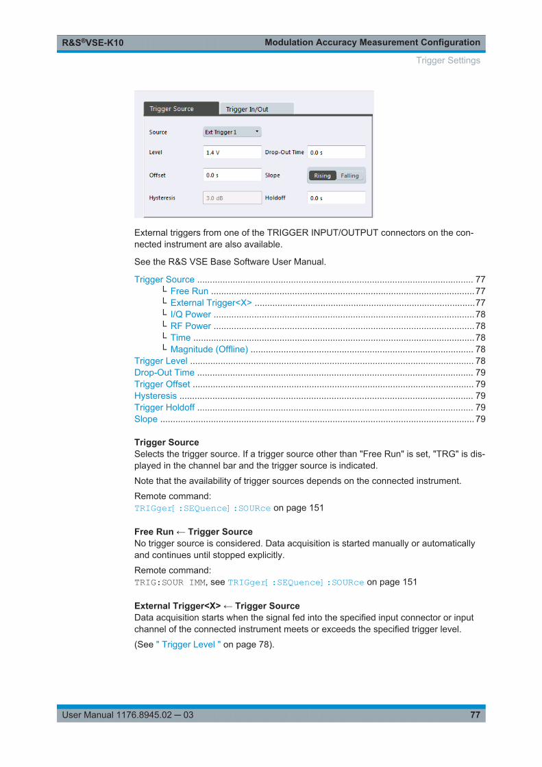
Modulation Accuracy Measurement ConfigurationR&S®VSE-K10
77User Manual 1176.8945.02 ─ 03
External triggers from one of the TRIGGER INPUT/OUTPUT connectors on the con-nected instrument are also available.
See the R&S VSE Base Software User Manual.
Trigger Source ............................................................................................................. 77└ Free Run ........................................................................................................77└ External Trigger<X> .......................................................................................77└ I/Q Power .......................................................................................................78└ RF Power .......................................................................................................78└ Time ...............................................................................................................78└ Magnitude (Offline) ........................................................................................ 78
Trigger Level ................................................................................................................ 78Drop-Out Time ............................................................................................................. 79Trigger Offset ............................................................................................................... 79Hysteresis .................................................................................................................... 79Trigger Holdoff ............................................................................................................. 79Slope ............................................................................................................................ 79
Trigger SourceSelects the trigger source. If a trigger source other than "Free Run" is set, "TRG" is dis-played in the channel bar and the trigger source is indicated.
Note that the availability of trigger sources depends on the connected instrument.
Remote command: TRIGger[:SEQuence]:SOURce on page 151
Free Run ← Trigger SourceNo trigger source is considered. Data acquisition is started manually or automaticallyand continues until stopped explicitly.
Remote command: TRIG:SOUR IMM, see TRIGger[:SEQuence]:SOURce on page 151
External Trigger<X> ← Trigger SourceData acquisition starts when the signal fed into the specified input connector or inputchannel of the connected instrument meets or exceeds the specified trigger level.
(See " Trigger Level " on page 78).
Trigger Settings
Modulation Accuracy Measurement ConfigurationR&S®VSE-K10
78User Manual 1176.8945.02 ─ 03
Note: Which input and output connectors are available depends on the connectedinstrument. For details, see the instrument's documentation.For a connected R&S RTO, the following signals are used as trigger input:● "External Trigger 1" : EXT TRIGGER INPUT connector on rear panel of instrument● "External Trigger 1" / "External Trigger 2" / "External Trigger 3" : Input at channel
connectors CH 2/3/4 on front panel of instrument
Remote command: TRIG:SOUR EXT, TRIG:SOUR EXT2, TRIG:SOUR EXT3, TRIG:SOUR EXT4See TRIGger[:SEQuence]:SOURce on page 151
I/Q Power ← Trigger SourceTriggers the measurement when the magnitude of the sampled I/Q data exceeds thetrigger threshold.
Remote command: TRIG:SOUR IQP, see TRIGger[:SEQuence]:SOURce on page 151
RF Power ← Trigger SourceDefines triggering of the measurement via signals which are outside the displayedmeasurement range.
For this purpose, the software uses a level detector at the first intermediate frequency.
The resulting trigger level at the RF input depends on the RF attenuation and preampli-fication. For details on available trigger levels, see the instrument's data sheet.
Note: If the input signal contains frequencies outside of this range (e.g. for fullspanmeasurements), the measurement may be aborted. A message indicating the allowedinput frequencies is displayed in the status bar.A "Trigger Offset" , "Trigger Polarity" and "Trigger Holdoff" (to improve the trigger sta-bility) can be defined for the RF trigger, but no "Hysteresis" .
Remote command: TRIG:SOUR RFP, see TRIGger[:SEQuence]:SOURce on page 151
Time ← Trigger SourceTriggers in a specified repetition interval.
Remote command: TRIG:SOUR TIME, see TRIGger[:SEQuence]:SOURce on page 151
Magnitude (Offline) ← Trigger SourceFor (offline) input from a file, rather than an instrument. Triggers on a specified signallevel.
Remote command: TRIG:SOUR MAGN, see TRIGger[:SEQuence]:SOURce on page 151
Trigger LevelDefines the trigger level for the specified trigger source.
For details on supported trigger levels, see the data sheet.
Trigger Settings
Modulation Accuracy Measurement ConfigurationR&S®VSE-K10
79User Manual 1176.8945.02 ─ 03
Remote command: TRIGger[:SEQuence]:LEVel:IFPower on page 149TRIGger[:SEQuence]:LEVel:IQPower on page 149TRIGger[:SEQuence]:LEVel[:EXTernal<port>] on page 148TRIGger[:SEQuence]:LEVel:RFPower on page 150
Drop-Out TimeDefines the time the input signal must stay below the trigger level before triggeringagain.
Remote command: TRIGger[:SEQuence]:DTIMe on page 147
Trigger OffsetDefines the time offset between the trigger event and the start of the measurement.
Note: When using an external trigger, the trigger offset is particularly important todetect the frame start correctly! (See Chapter 5.5, "Trigger settings", on page 35.) TheR&S VSE GSM application expects the trigger event to be the start of the "active part"in slot 0.
Offset > 0: Start of the measurement is delayed
Offset < 0: Measurement starts earlier (pretrigger)
(If supported by the connected instrument.)
Remote command: TRIGger[:SEQuence]:HOLDoff[:TIME] on page 148
HysteresisDefines the distance in dB to the trigger level that the trigger source must exceedbefore a trigger event occurs. Setting a hysteresis avoids unwanted trigger eventscaused by noise oscillation around the trigger level.
This setting is only available for "IF Power" or "Magnitude (Offline)" trigger sources.The range of the value depends on the connected instrument.
Remote command: TRIGger[:SEQuence]:IFPower:HYSTeresis on page 148TRIGger[:SEQuence]:MAPower:HYSTeresis on page 150
Trigger HoldoffDefines the minimum time (in seconds) that must pass between two trigger events.Trigger events that occur during the holdoff time are ignored.
Remote command: TRIGger[:SEQuence]:IFPower:HOLDoff on page 148TRIGger[:SEQuence]:MAPower:HOLDoff on page 150
SlopeFor all trigger sources except time, you can define whether triggering occurs when thesignal rises to the trigger level or falls down to it.
Trigger Settings
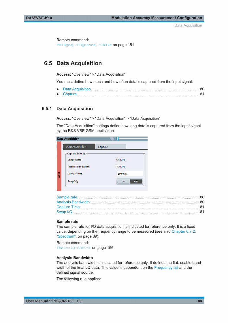
Modulation Accuracy Measurement ConfigurationR&S®VSE-K10
80User Manual 1176.8945.02 ─ 03
Remote command: TRIGger[:SEQuence]:SLOPe on page 151
6.5 Data Acquisition
Access: "Overview" > "Data Acquisition"
You must define how much and how often data is captured from the input signal.
● Data Acquisition...................................................................................................... 80● Capture................................................................................................................... 81
6.5.1 Data Acquisition
Access: "Overview" > "Data Acquisition" > "Data Acquisition"
The "Data Acquisition" settings define how long data is captured from the input signalby the R&S VSE GSM application.
Sample rate...................................................................................................................80Analysis Bandwidth....................................................................................................... 80Capture Time................................................................................................................ 81Swap I/Q ...................................................................................................................... 81
Sample rateThe sample rate for I/Q data acquisition is indicated for reference only. It is a fixedvalue, depending on the frequency range to be measured (see also Chapter 6.7.2,"Spectrum", on page 89).
Remote command: TRACe:IQ:SRATe? on page 156
Analysis BandwidthThe analysis bandwidth is indicated for reference only. It defines the flat, usable band-width of the final I/Q data. This value is dependent on the Frequency list and thedefined signal source.
The following rule applies:
Data Acquisition
Modulation Accuracy Measurement ConfigurationR&S®VSE-K10
81User Manual 1176.8945.02 ─ 03
analysis bandwidth = 0.8 * sample rate
Remote command: TRACe:IQ:BWIDth? on page 157
Capture TimeSpecifies the duration (and therefore the amount of data) to be captured in the capturebuffer.
Be sure to define a sufficiently long capture time. If the capture time is too short,demodulation will fail.
Note: The duration of one GSM slot equals 15/26 ms = 0.576923 ms. The duration ofone GSM frame (8 slots) equals 60/13 ms = 4.615384 ms.Tip: In order to improve the measurement speed further by using short capture times,consider the following:● Use an external trigger which indicates the frame start. In this case, the minimum
allowed capture time is reduced from 10 ms to 866 us (see Chapter 5.5, "Triggersettings", on page 35)
● Measure only slots at the beginning of the frame, directly after the trigger (seeChapter 6.6.1, "Slot Scope", on page 82)
● Use a small statistic count (see "Statistic Count" on page 82)
Remote command: [SENSe:]SWEep:TIME on page 156
Swap I/QActivates or deactivates the inverted I/Q modulation. If the I and Q parts of the signalfrom the DUT are interchanged, the R&S VSE can do the same to compensate for it.
Tip: Try this function if the TSC cannot be found.
On I and Q signals are interchanged
Inverted sideband, Q+j*I
Off I and Q signals are not interchanged
Normal sideband, I+j*Q
Remote command: [SENSe:]SWAPiq on page 156
6.5.2 Capture
Access: "Overview" > "Data Acquisition" > "Capture"
The "Capture" settings define how often data is captured from the input signal by theR&S VSE GSM application.
Data Acquisition
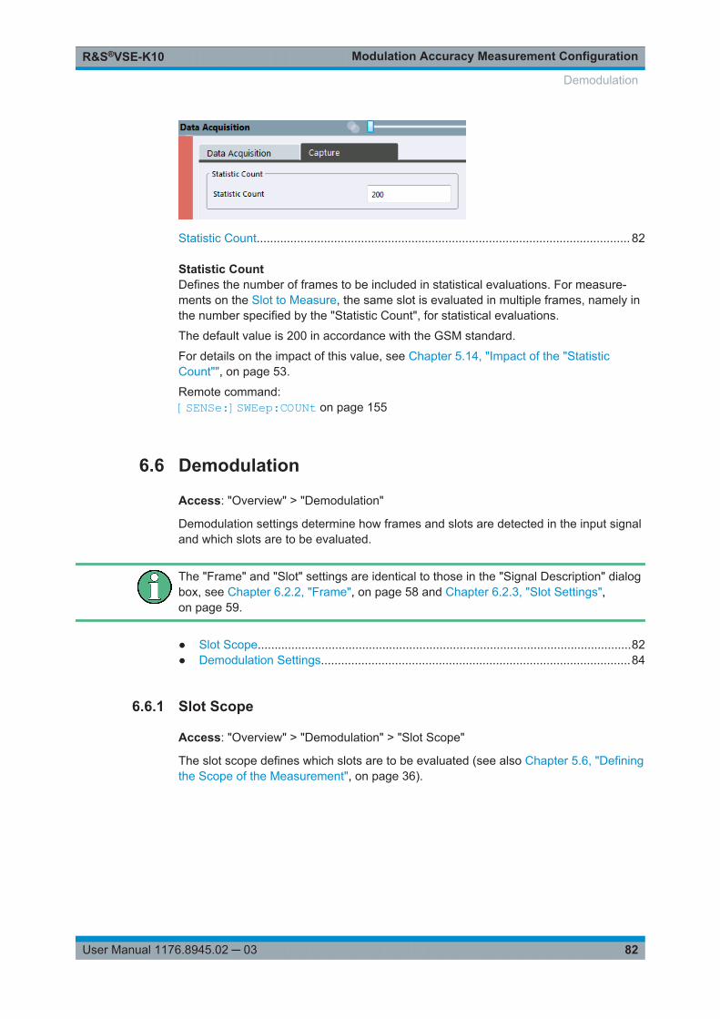
Modulation Accuracy Measurement ConfigurationR&S®VSE-K10
82User Manual 1176.8945.02 ─ 03
Statistic Count............................................................................................................... 82
Statistic CountDefines the number of frames to be included in statistical evaluations. For measure-ments on the Slot to Measure, the same slot is evaluated in multiple frames, namely inthe number specified by the "Statistic Count", for statistical evaluations.
The default value is 200 in accordance with the GSM standard.
For details on the impact of this value, see Chapter 5.14, "Impact of the "StatisticCount"", on page 53.
Remote command: [SENSe:]SWEep:COUNt on page 155
6.6 Demodulation
Access: "Overview" > "Demodulation"
Demodulation settings determine how frames and slots are detected in the input signaland which slots are to be evaluated.
The "Frame" and "Slot" settings are identical to those in the "Signal Description" dialogbox, see Chapter 6.2.2, "Frame", on page 58 and Chapter 6.2.3, "Slot Settings",on page 59.
● Slot Scope...............................................................................................................82● Demodulation Settings............................................................................................84
6.6.1 Slot Scope
Access: "Overview" > "Demodulation" > "Slot Scope"
The slot scope defines which slots are to be evaluated (see also Chapter 5.6, "Definingthe Scope of the Measurement", on page 36).
Demodulation
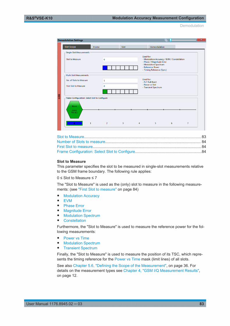
Modulation Accuracy Measurement ConfigurationR&S®VSE-K10
83User Manual 1176.8945.02 ─ 03
Slot to Measure............................................................................................................. 83Number of Slots to measure......................................................................................... 84First Slot to measure..................................................................................................... 84Frame Configuration: Select Slot to Configure..............................................................84
Slot to MeasureThis parameter specifies the slot to be measured in single-slot measurements relativeto the GSM frame boundary. The following rule applies:
0 ≤ Slot to Measure ≤ 7
The "Slot to Measure" is used as the (only) slot to measure in the following measure-ments: (see "First Slot to measure" on page 84)● Modulation Accuracy● EVM● Phase Error● Magnitude Error● Modulation Spectrum● ConstellationFurthermore, the "Slot to Measure" is used to measure the reference power for the fol-lowing measurements:● Power vs Time● Modulation Spectrum● Transient SpectrumFinally, the "Slot to Measure" is used to measure the position of its TSC, which repre-sents the timing reference for the Power vs Time mask (limit lines) of all slots.
See also Chapter 5.6, "Defining the Scope of the Measurement", on page 36. Fordetails on the measurement types see Chapter 4, "GSM I/Q Measurement Results",on page 12.
Demodulation
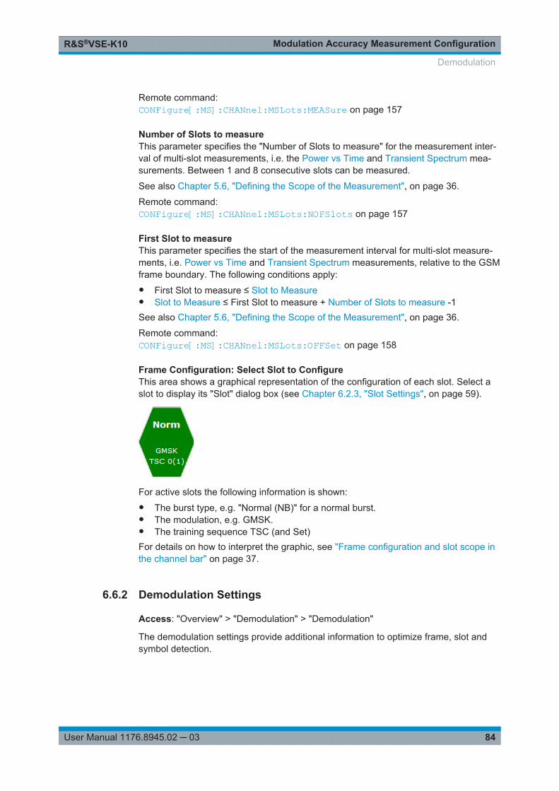
Modulation Accuracy Measurement ConfigurationR&S®VSE-K10
84User Manual 1176.8945.02 ─ 03
Remote command: CONFigure[:MS]:CHANnel:MSLots:MEASure on page 157
Number of Slots to measureThis parameter specifies the "Number of Slots to measure" for the measurement inter-val of multi-slot measurements, i.e. the Power vs Time and Transient Spectrum mea-surements. Between 1 and 8 consecutive slots can be measured.
See also Chapter 5.6, "Defining the Scope of the Measurement", on page 36.
Remote command: CONFigure[:MS]:CHANnel:MSLots:NOFSlots on page 157
First Slot to measureThis parameter specifies the start of the measurement interval for multi-slot measure-ments, i.e. Power vs Time and Transient Spectrum measurements, relative to the GSMframe boundary. The following conditions apply:● First Slot to measure ≤ Slot to Measure● Slot to Measure ≤ First Slot to measure + Number of Slots to measure -1See also Chapter 5.6, "Defining the Scope of the Measurement", on page 36.
Remote command: CONFigure[:MS]:CHANnel:MSLots:OFFSet on page 158
Frame Configuration: Select Slot to ConfigureThis area shows a graphical representation of the configuration of each slot. Select aslot to display its "Slot" dialog box (see Chapter 6.2.3, "Slot Settings", on page 59).
For active slots the following information is shown:● The burst type, e.g. "Normal (NB)" for a normal burst.● The modulation, e.g. GMSK.● The training sequence TSC (and Set)For details on how to interpret the graphic, see "Frame configuration and slot scope inthe channel bar" on page 37.
6.6.2 Demodulation Settings
Access: "Overview" > "Demodulation" > "Demodulation"
The demodulation settings provide additional information to optimize frame, slot andsymbol detection.
Demodulation
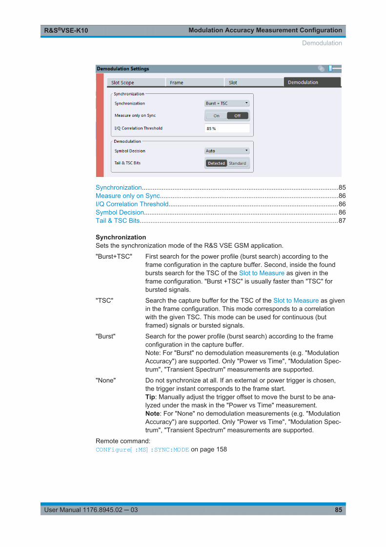
Modulation Accuracy Measurement ConfigurationR&S®VSE-K10
85User Manual 1176.8945.02 ─ 03
Synchronization.............................................................................................................85Measure only on Sync...................................................................................................86I/Q Correlation Threshold..............................................................................................86Symbol Decision........................................................................................................... 86Tail & TSC Bits..............................................................................................................87
SynchronizationSets the synchronization mode of the R&S VSE GSM application.
"Burst+TSC" First search for the power profile (burst search) according to theframe configuration in the capture buffer. Second, inside the foundbursts search for the TSC of the Slot to Measure as given in theframe configuration. "Burst +TSC" is usually faster than "TSC" forbursted signals.
"TSC" Search the capture buffer for the TSC of the Slot to Measure as givenin the frame configuration. This mode corresponds to a correlationwith the given TSC. This mode can be used for continuous (butframed) signals or bursted signals.
"Burst" Search for the power profile (burst search) according to the frameconfiguration in the capture buffer.Note: For "Burst" no demodulation measurements (e.g. "ModulationAccuracy") are supported. Only "Power vs Time", "Modulation Spec-trum", "Transient Spectrum" measurements are supported.
"None" Do not synchronize at all. If an external or power trigger is chosen,the trigger instant corresponds to the frame start.Tip: Manually adjust the trigger offset to move the burst to be ana-lyzed under the mask in the "Power vs Time" measurement.Note: For "None" no demodulation measurements (e.g. "ModulationAccuracy") are supported. Only "Power vs Time", "Modulation Spec-trum", "Transient Spectrum" measurements are supported.
Remote command: CONFigure[:MS]:SYNC:MODE on page 158
Demodulation
Modulation Accuracy Measurement ConfigurationR&S®VSE-K10
86User Manual 1176.8945.02 ─ 03
Measure only on SyncIf activated (default), only results from frames (slots) where the Slot to Measure wasfound are displayed and taken into account in the averaging of the results. The behav-ior of this option depends on the value of the Synchronization parameter.
Remote command: CONFigure[:MS]:SYNC:ONLY on page 159
I/Q Correlation ThresholdThis threshold determines whether a burst is accepted if Measure only on Sync is acti-vated. If the correlation value between the ideal I/Q signal of the given TSC and themeasured TSC is below the I/Q correlation threshold, then the application reports"Sync not found" in the status bar. Additionally, such bursts are ignored if "Measureonly on Sync" is activated.
Note: If the R&S VSE GSM application is configured to measure GMSK normal bursts,a threshold below 97% will also accept 8PSK normal bursts (with the same TSC) foranalysis. In this case, activate Measure only on Sync and set the "I/Q CorrelationThreshold" to 97%. This will exclude the 8PSK normal bursts from the analysis.
Remote command: CONFigure[:MS]:SYNC:IQCThreshold on page 160
Symbol DecisionThe symbol decision determines how the symbols are detected in the demodulator.Setting this parameter does not affect the demodulation of normal bursts with GMSKmodulator. For normal bursts with 8PSK, 16QAM, 32QAM or AQPSK modulation, orhigher symbol rate bursts with QPSK, 16QAM or 32QAM modulation, use this parame-ter to get a trade-off between performance (symbol error rate of the R&S VSE GSMapplication) and measurement speed.
"Auto" Automatically selects the symbol decision method.
"Linear" Linear symbol decision: Uses inverse filtering (a kind of zero-forcingfilter) and a symbol-wise decision method. This method is recommen-ded for high symbol to noise ratios, but not for higher symbol ratebursts with a narrow pulse. The inverse filter colors the noise insidethe signal bandwidth and therefore is not recommended for narrow-band signals or signals with a low signal to noise ratio. Peaks in the"EVM vs Time" measurement (see "EVM" on page 13) may occur ifthe "Linear" symbol decision algorithm fails. In that case use the"Sequence" method. Linear is the fastest option.
"Sequence" Symbol decision via sequence estimation. This method uses an algo-rithm that minimizes the symbol errors of the entire burst. It requiresthat the tail bits in the analyzed signal are correct. It has a better per-formance (lower symbol error rate) compared to the "Linear" method,especially at low signal to noise ratios, but with a loss of measure-ment speed. This method is recommended for normal bursts with16QAM or 32QAM modulation and for Higher Symbol Rate burstswith a narrow pulse.Tip: Use this setting if it reduces the EVM RMS measurement result.
Remote command: CONFigure[:MS]:DEMod:DECision on page 160
Demodulation
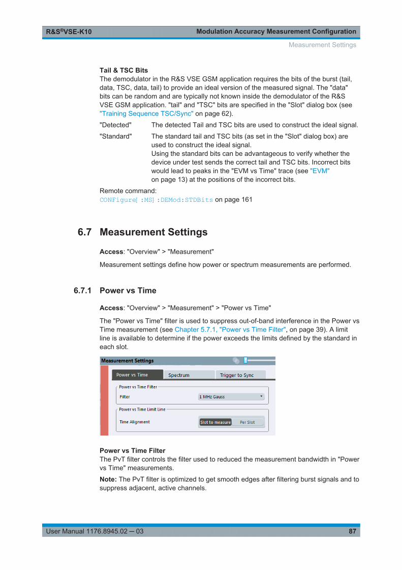
Modulation Accuracy Measurement ConfigurationR&S®VSE-K10
87User Manual 1176.8945.02 ─ 03
Tail & TSC BitsThe demodulator in the R&S VSE GSM application requires the bits of the burst (tail,data, TSC, data, tail) to provide an ideal version of the measured signal. The "data"bits can be random and are typically not known inside the demodulator of the R&SVSE GSM application. "tail" and "TSC" bits are specified in the "Slot" dialog box (see"Training Sequence TSC/Sync" on page 62).
"Detected" The detected Tail and TSC bits are used to construct the ideal signal.
"Standard" The standard tail and TSC bits (as set in the "Slot" dialog box) areused to construct the ideal signal.Using the standard bits can be advantageous to verify whether thedevice under test sends the correct tail and TSC bits. Incorrect bitswould lead to peaks in the "EVM vs Time" trace (see "EVM"on page 13) at the positions of the incorrect bits.
Remote command: CONFigure[:MS]:DEMod:STDBits on page 161
6.7 Measurement Settings
Access: "Overview" > "Measurement"
Measurement settings define how power or spectrum measurements are performed.
6.7.1 Power vs Time
Access: "Overview" > "Measurement" > "Power vs Time"
The "Power vs Time" filter is used to suppress out-of-band interference in the Power vsTime measurement (see Chapter 5.7.1, "Power vs Time Filter", on page 39). A limitline is available to determine if the power exceeds the limits defined by the standard ineach slot.
Power vs Time FilterThe PvT filter controls the filter used to reduced the measurement bandwidth in "Powervs Time" measurements.
Note: The PvT filter is optimized to get smooth edges after filtering burst signals and tosuppress adjacent, active channels.
Measurement Settings
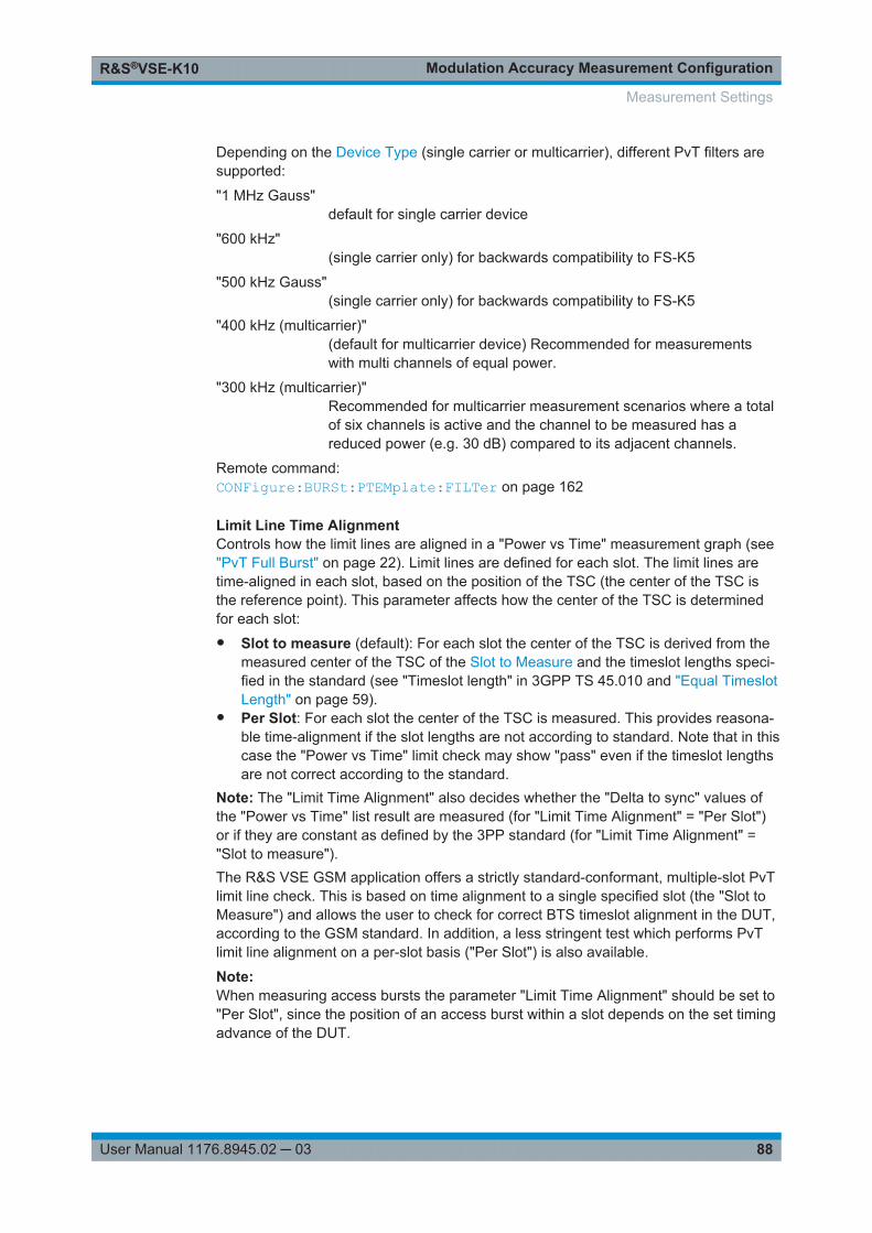
Modulation Accuracy Measurement ConfigurationR&S®VSE-K10
88User Manual 1176.8945.02 ─ 03
Depending on the Device Type (single carrier or multicarrier), different PvT filters aresupported:
"1 MHz Gauss"default for single carrier device
"600 kHz"(single carrier only) for backwards compatibility to FS-K5
"500 kHz Gauss"(single carrier only) for backwards compatibility to FS-K5
"400 kHz (multicarrier)"(default for multicarrier device) Recommended for measurementswith multi channels of equal power.
"300 kHz (multicarrier)"Recommended for multicarrier measurement scenarios where a totalof six channels is active and the channel to be measured has areduced power (e.g. 30 dB) compared to its adjacent channels.
Remote command: CONFigure:BURSt:PTEMplate:FILTer on page 162
Limit Line Time AlignmentControls how the limit lines are aligned in a "Power vs Time" measurement graph (see"PvT Full Burst" on page 22). Limit lines are defined for each slot. The limit lines aretime-aligned in each slot, based on the position of the TSC (the center of the TSC isthe reference point). This parameter affects how the center of the TSC is determinedfor each slot:● Slot to measure (default): For each slot the center of the TSC is derived from the
measured center of the TSC of the Slot to Measure and the timeslot lengths speci-fied in the standard (see "Timeslot length" in 3GPP TS 45.010 and "Equal TimeslotLength" on page 59).
● Per Slot: For each slot the center of the TSC is measured. This provides reasona-ble time-alignment if the slot lengths are not according to standard. Note that in thiscase the "Power vs Time" limit check may show "pass" even if the timeslot lengthsare not correct according to the standard.
Note: The "Limit Time Alignment" also decides whether the "Delta to sync" values ofthe "Power vs Time" list result are measured (for "Limit Time Alignment" = "Per Slot")or if they are constant as defined by the 3PP standard (for "Limit Time Alignment" ="Slot to measure").The R&S VSE GSM application offers a strictly standard-conformant, multiple-slot PvTlimit line check. This is based on time alignment to a single specified slot (the "Slot toMeasure") and allows the user to check for correct BTS timeslot alignment in the DUT,according to the GSM standard. In addition, a less stringent test which performs PvTlimit line alignment on a per-slot basis ("Per Slot") is also available.
Note:When measuring access bursts the parameter "Limit Time Alignment" should be set to"Per Slot", since the position of an access burst within a slot depends on the set timingadvance of the DUT.
Measurement Settings
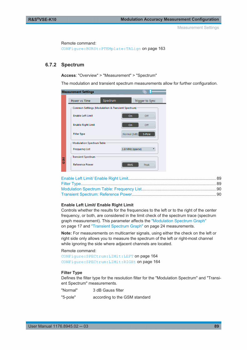
Modulation Accuracy Measurement ConfigurationR&S®VSE-K10
89User Manual 1176.8945.02 ─ 03
Remote command: CONFigure:BURSt:PTEMplate:TALign on page 163
6.7.2 Spectrum
Access: "Overview" > "Measurement" > "Spectrum"
The modulation and transient spectrum measurements allow for further configuration.
Enable Left Limit/ Enable Right Limit............................................................................ 89Filter Type..................................................................................................................... 89Modulation Spectrum Table: Frequency List.................................................................90Transient Spectrum: Reference Power......................................................................... 90
Enable Left Limit/ Enable Right LimitControls whether the results for the frequencies to the left or to the right of the centerfrequency, or both, are considered in the limit check of the spectrum trace (spectrumgraph measurement). This parameter affects the "Modulation Spectrum Graph"on page 17 and "Transient Spectrum Graph" on page 24 measurements.
Note: For measurements on multicarrier signals, using either the check on the left orright side only allows you to measure the spectrum of the left or right-most channelwhile ignoring the side where adjacent channels are located.
Remote command: CONFigure:SPECtrum:LIMit:LEFT on page 164CONFigure:SPECtrum:LIMit:RIGHt on page 164
Filter TypeDefines the filter type for the resolution filter for the "Modulation Spectrum" and "Transi-ent Spectrum" measurements.
"Normal" 3 dB Gauss filter
"5-pole" according to the GSM standard
Measurement Settings
Modulation Accuracy Measurement ConfigurationR&S®VSE-K10
90User Manual 1176.8945.02 ─ 03
Remote command: [SENSe:]BANDwidth[:RESolution]:TYPE on page 166
Modulation Spectrum Table: Frequency ListThis setting is only required by the "Modulation Spectrum Table" evaluation (see "Mod-ulation Spectrum Table" on page 18). In this evaluation, the spectrum of the signal atfixed frequency offsets is determined. The list of frequencies to be measured is definedby the standard. Additionally, sparse versions of the specified frequency lists withfewer intermediate frequencies are provided for quicker preliminary tests.
Note: Modulation RBW at 1800 kHz.As opposed to previous R&S signal and spectrum analyzers, in which the modulationRBW at 1800 kHz was configurable, the R&S VSE configures the RBW (and VBW)internally according to the selected frequency list (see "Modulation Spectrum Table:Frequency List" on page 90). For the "Modulation Spectrum Graph" both the RBW andVBW are set to 30 kHz. For the "Modulation Spectrum Table", they are set accordingto Table 4-6.The frequency list also determines the used sample rate, see "Sample rate"on page 80).
"1.8 MHz" The frequency list comprises offset frequencies up to 1.8 MHz fromthe carrier. The sample rate is 6.5 MHz.In previous R&S signal and spectrum analyzers, this setting wasreferred to as "narrow".
"1.8 MHz(sparse)"
More compact version of "1.8 MHz". The sample rate is 6.5 MHz.
"6 MHz" The frequency list comprises offset frequencies up to 6 MHz from thecarrier. The sample rate is 19.5 MHz.In previous R&S signal and spectrum analyzers, this setting wasreferred to as "wide".
"6 MHz(sparse)"
More compact version of "6 MHz". The sample rate is 19.5 MHz.
Remote command: CONFigure:WSPectrum:MODulation:LIST:SELect on page 166
Transient Spectrum: Reference PowerThis setting is only required by the "Transient Spectrum" evaluation (see TransientSpectrum Graph).
In this evaluation, the power vs spectrum for all slots in the slot scope is evaluated andchecked against a spectrum mask. To determine the relative limit values, a referencepower is required. In order to detect irregularities, it is useful to define the peak poweras a reference. However, the standard requires the reference power to be calculatedfrom the RMS power.
To perform the measurement according to the 3GPP standard set the reference powerto RMS and the Slot to Measure to the slot with the highest power (see also "TransientSpectrum Table" on page 25).
"RMS" (Default:) The reference power is the RMS power level measuredover the useful part of the Slot to Measure and averaged according tothe defined Statistic Count.
Measurement Settings
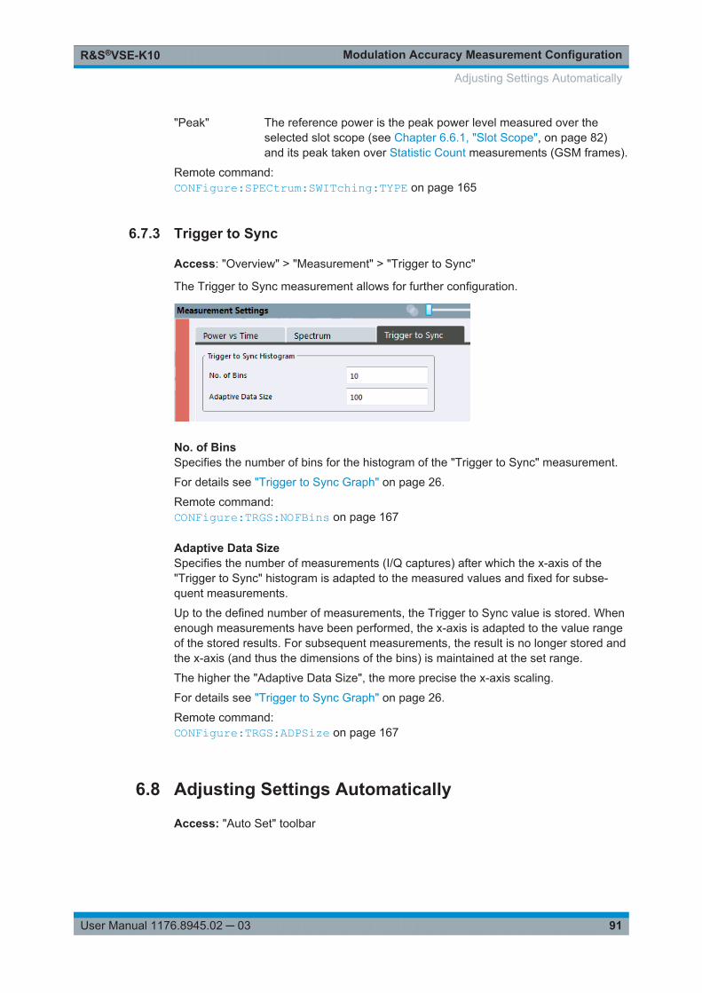
Modulation Accuracy Measurement ConfigurationR&S®VSE-K10
91User Manual 1176.8945.02 ─ 03
"Peak" The reference power is the peak power level measured over theselected slot scope (see Chapter 6.6.1, "Slot Scope", on page 82)and its peak taken over Statistic Count measurements (GSM frames).
Remote command: CONFigure:SPECtrum:SWITching:TYPE on page 165
6.7.3 Trigger to Sync
Access: "Overview" > "Measurement" > "Trigger to Sync"
The Trigger to Sync measurement allows for further configuration.
No. of BinsSpecifies the number of bins for the histogram of the "Trigger to Sync" measurement.
For details see "Trigger to Sync Graph" on page 26.
Remote command: CONFigure:TRGS:NOFBins on page 167
Adaptive Data SizeSpecifies the number of measurements (I/Q captures) after which the x-axis of the"Trigger to Sync" histogram is adapted to the measured values and fixed for subse-quent measurements.
Up to the defined number of measurements, the Trigger to Sync value is stored. Whenenough measurements have been performed, the x-axis is adapted to the value rangeof the stored results. For subsequent measurements, the result is no longer stored andthe x-axis (and thus the dimensions of the bins) is maintained at the set range.
The higher the "Adaptive Data Size", the more precise the x-axis scaling.
For details see "Trigger to Sync Graph" on page 26.
Remote command: CONFigure:TRGS:ADPSize on page 167
6.8 Adjusting Settings Automatically
Access: "Auto Set" toolbar
Adjusting Settings Automatically
Modulation Accuracy Measurement ConfigurationR&S®VSE-K10
92User Manual 1176.8945.02 ─ 03
Some settings can be adjusted by the R&S VSE automatically according to the currentmeasurement settings.
Setting the Reference Level Automatically (Auto Level)............................................... 92Automatic Frame Configuration.................................................................................... 92Automatic Trigger Offset............................................................................................... 92
Setting the Reference Level Automatically (Auto Level)Automatically determines the optimal reference level for the current input data. At thesame time, the internal attenuators and the preamplifier are adjusted so the signal-to-noise ratio is optimized, while signal compression, clipping and overload conditions areminimized.
In order to do so, a level measurement is performed to determine the optimal referencelevel.
Remote command: CONFigure[:MS]:AUTO:LEVel ONCE on page 168
Automatic Frame ConfigurationWhen activated, a single auto frame configuration measurement is performed.
The auto frame configuration measurement may take a long time, therefore it is deacti-vated by default. The following parameters are detected and automatically measured:● Active slots● Slot configuration (burst type, modulation, filter, TSC)● Equal time slot length● For VAMOS normal burst and GMSK: TSCs of set 1 and set 2● For VAMOS normal burst and AQPSK: TSCs of both subchannels (restrictions see
"Restriction for auto frame configuration" on page 34) and SCPIR
Remote command: CONF:AUTO:FRAM ONCE, see CONFigure[:MS]:AUTO:FRAMe ONCE on page 168
Automatic Trigger OffsetIf activated, the trigger offset (for external and IF power triggers) are detected andautomatically measured.
For details on the trigger offset refer to " Trigger Offset " on page 79.
Remote command: CONF:AUTO:TRIG ONCE, see CONFigure[:MS]:AUTO:TRIGger ONCEon page 168
6.9 Result Configuration
Access: "Overview" > "Result Config"
or: "Meas Setup" > "Result"
Some evaluation methods require or allow for additional settings to configure the resultdisplay. Note that the available settings depend on the selected window (see " Specif-ics for " on page 56).
Result Configuration
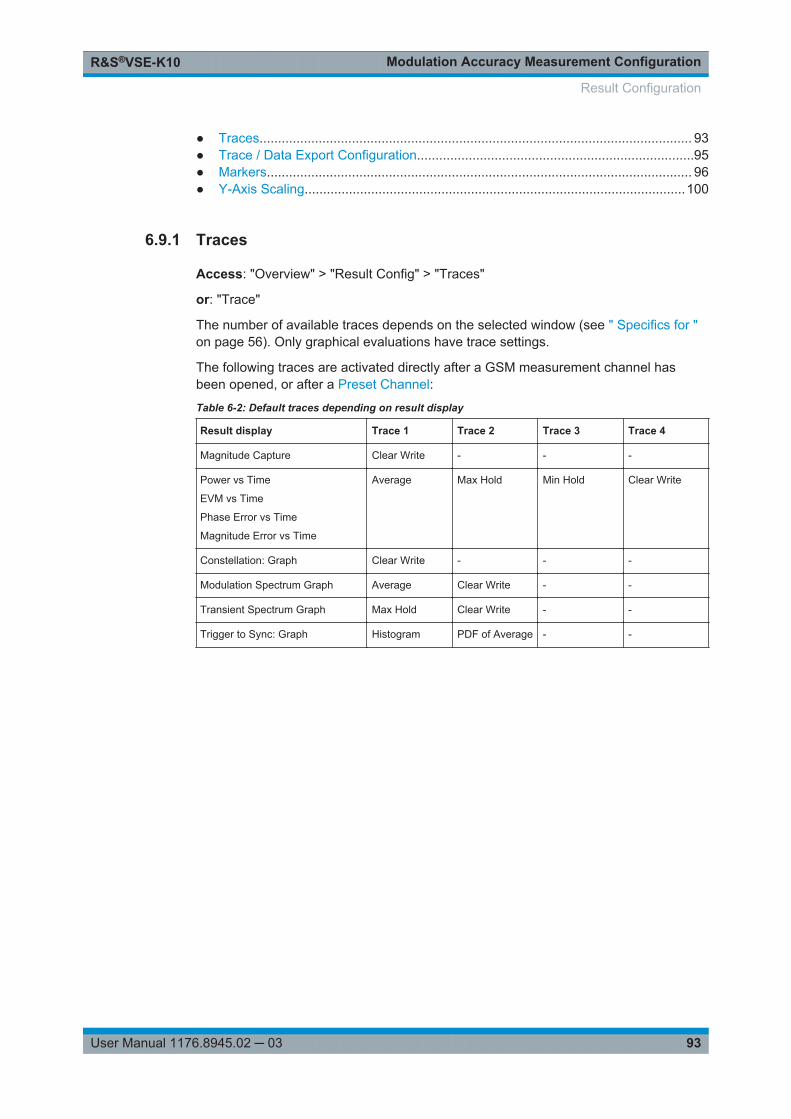
Modulation Accuracy Measurement ConfigurationR&S®VSE-K10
93User Manual 1176.8945.02 ─ 03
● Traces..................................................................................................................... 93● Trace / Data Export Configuration...........................................................................95● Markers................................................................................................................... 96● Y-Axis Scaling.......................................................................................................100
6.9.1 Traces
Access: "Overview" > "Result Config" > "Traces"
or: "Trace"
The number of available traces depends on the selected window (see " Specifics for "on page 56). Only graphical evaluations have trace settings.
The following traces are activated directly after a GSM measurement channel hasbeen opened, or after a Preset Channel:
Table 6-2: Default traces depending on result display
Result display Trace 1 Trace 2 Trace 3 Trace 4
Magnitude Capture Clear Write - - -
Power vs Time
EVM vs Time
Phase Error vs Time
Magnitude Error vs Time
Average Max Hold Min Hold Clear Write
Constellation: Graph Clear Write - - -
Modulation Spectrum Graph Average Clear Write - -
Transient Spectrum Graph Max Hold Clear Write - -
Trigger to Sync: Graph Histogram PDF of Average - -
Result Configuration
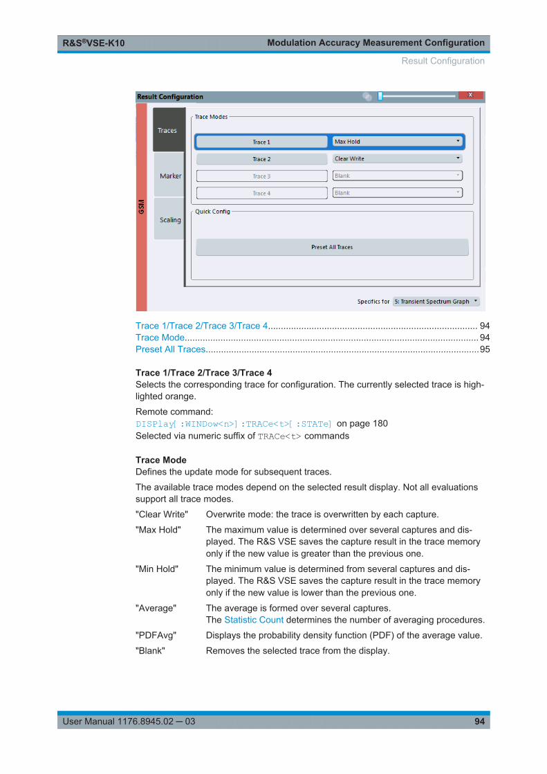
Modulation Accuracy Measurement ConfigurationR&S®VSE-K10
94User Manual 1176.8945.02 ─ 03
Trace 1/Trace 2/Trace 3/Trace 4.................................................................................. 94Trace Mode................................................................................................................... 94Preset All Traces...........................................................................................................95
Trace 1/Trace 2/Trace 3/Trace 4Selects the corresponding trace for configuration. The currently selected trace is high-lighted orange.
Remote command: DISPlay[:WINDow<n>]:TRACe<t>[:STATe] on page 180Selected via numeric suffix of TRACe<t> commands
Trace ModeDefines the update mode for subsequent traces.
The available trace modes depend on the selected result display. Not all evaluationssupport all trace modes.
"Clear Write" Overwrite mode: the trace is overwritten by each capture.
"Max Hold" The maximum value is determined over several captures and dis-played. The R&S VSE saves the capture result in the trace memoryonly if the new value is greater than the previous one.
"Min Hold" The minimum value is determined from several captures and dis-played. The R&S VSE saves the capture result in the trace memoryonly if the new value is lower than the previous one.
"Average" The average is formed over several captures.The Statistic Count determines the number of averaging procedures.
"PDFAvg" Displays the probability density function (PDF) of the average value.
"Blank" Removes the selected trace from the display.
Result Configuration
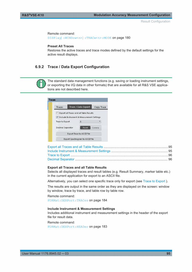
Modulation Accuracy Measurement ConfigurationR&S®VSE-K10
95User Manual 1176.8945.02 ─ 03
Remote command: DISPlay[:WINDow<n>]:TRACe<t>:MODE on page 180
Preset All TracesRestores the active traces and trace modes defined by the default settings for theactive result displays.
6.9.2 Trace / Data Export Configuration
The standard data management functions (e.g. saving or loading instrument settings,or exporting the I/Q data in other formats) that are available for all R&S VSE applica-tions are not described here.
Export all Traces and all Table Results ........................................................................95Include Instrument & Measurement Settings ............................................................... 95Trace to Export .............................................................................................................96Decimal Separator ....................................................................................................... 96
Export all Traces and all Table ResultsSelects all displayed traces and result tables (e.g. Result Summary, marker table etc.)in the current application for export to an ASCII file.
Alternatively, you can select one specific trace only for export (see Trace to Export ).
The results are output in the same order as they are displayed on the screen: windowby window, trace by trace, and table row by table row.
Remote command: FORMat:DEXPort:TRACes on page 184
Include Instrument & Measurement SettingsIncludes additional instrument and measurement settings in the header of the exportfile for result data.
Remote command: FORMat:DEXPort:HEADer on page 183
Result Configuration
Modulation Accuracy Measurement ConfigurationR&S®VSE-K10
96User Manual 1176.8945.02 ─ 03
Trace to ExportDefines an individual trace that will be exported to a file.
This setting is not available if Export all Traces and all Table Results is selected.
Decimal SeparatorDefines the decimal separator for floating-point numerals for the data export/importfiles. Evaluation programs require different separators in different languages.
Remote command: FORMat:DEXPort:DSEParator on page 183
6.9.3 Markers
Access: "Overview" > "Result Config" > "Marker"
or: "Marker"
Markers help you analyze your measurement results by determining particular valuesin the diagram. Thus you can extract numeric values from a graphical display. Up to 4markers can be configured.
● Individual Marker Settings.......................................................................................96● General Marker Settings......................................................................................... 99● Marker Positioning Functions..................................................................................99
6.9.3.1 Individual Marker Settings
Access: "Overview" > "Result Config" > "Marker" > "Markers"
or: "Marker" > "Marker"
In GSM evaluations, up to 4 markers can be activated in each diagram at any time.
Result Configuration
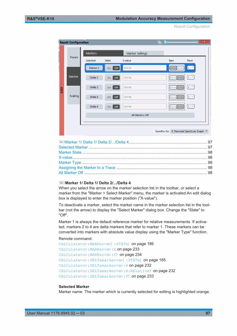
Modulation Accuracy Measurement ConfigurationR&S®VSE-K10
97User Manual 1176.8945.02 ─ 03
Marker 1/ Delta 1/ Delta 2/.../Delta 4....................................................................... 97Selected Marker ........................................................................................................... 97Marker State .................................................................................................................98X-value.......................................................................................................................... 98Marker Type ................................................................................................................. 98Assigning the Marker to a Trace .................................................................................. 98All Marker Off ............................................................................................................... 98
Marker 1/ Delta 1/ Delta 2/.../Delta 4When you select the arrow on the marker selection list in the toolbar, or select amarker from the "Marker > Select Marker" menu, the marker is activated.An edit dialogbox is displayed to enter the marker position ("X-value").
To deactivate a marker, select the marker name in the marker selection list in the tool-bar (not the arrow) to display the "Select Marker" dialog box. Change the "State" to"Off".
Marker 1 is always the default reference marker for relative measurements. If activa-ted, markers 2 to 4 are delta markers that refer to marker 1. These markers can beconverted into markers with absolute value display using the "Marker Type" function.
Remote command: CALCulate<n>:MARKer<m>[:STATe] on page 186CALCulate<n>:MARKer<m>:X on page 233CALCulate<n>:MARKer<m>:Y? on page 234CALCulate<n>:DELTamarker<m>[:STATe] on page 185CALCulate<n>:DELTamarker<m>:X on page 232CALCulate<n>:DELTamarker<m>:X:RELative? on page 232CALCulate<n>:DELTamarker<m>:Y? on page 233
Selected MarkerMarker name. The marker which is currently selected for editing is highlighted orange.
Result Configuration
Modulation Accuracy Measurement ConfigurationR&S®VSE-K10
98User Manual 1176.8945.02 ─ 03
Remote command: Marker selected via suffix <m> in remote commands.
Marker StateActivates or deactivates the marker in the diagram.
Remote command: CALCulate<n>:MARKer<m>[:STATe] on page 186CALCulate<n>:DELTamarker<m>[:STATe] on page 185
X-valueDefines the position of the marker on the x-axis (channel, slot, symbol, depending onevaluation).
Remote command: CALCulate<n>:DELTamarker<m>:X on page 232CALCulate<n>:MARKer<m>:X on page 233
Marker Type
Toggles the marker type.
The type for marker 1 is always "Normal" , the type for delta marker 1 is always "Delta" . These types cannot be changed.
Note: If normal marker 1 is the active marker, switching the "Mkr Type" activates anadditional delta marker 1. For any other marker, switching the marker type does notactivate an additional marker, it only switches the type of the selected marker.
"Normal" A normal marker indicates the absolute value at the defined positionin the diagram.
"Delta " A delta marker defines the value of the marker relative to the speci-fied reference marker (marker 1 by default).
Remote command: CALCulate<n>:MARKer<m>[:STATe] on page 186CALCulate<n>:DELTamarker<m>[:STATe] on page 185
Assigning the Marker to a TraceThe "Trace" setting assigns the selected marker to an active trace. The trace deter-mines which value the marker shows at the marker position. If the marker was previ-ously assigned to a different trace, the marker remains on the previous frequency ortime, but indicates the value of the new trace.
If a trace is turned off, the assigned markers and marker functions are also deactiva-ted.
Remote command: CALCulate<n>:MARKer<m>:TRACe on page 186
All Marker Off
Deactivates all markers in one step.
Result Configuration
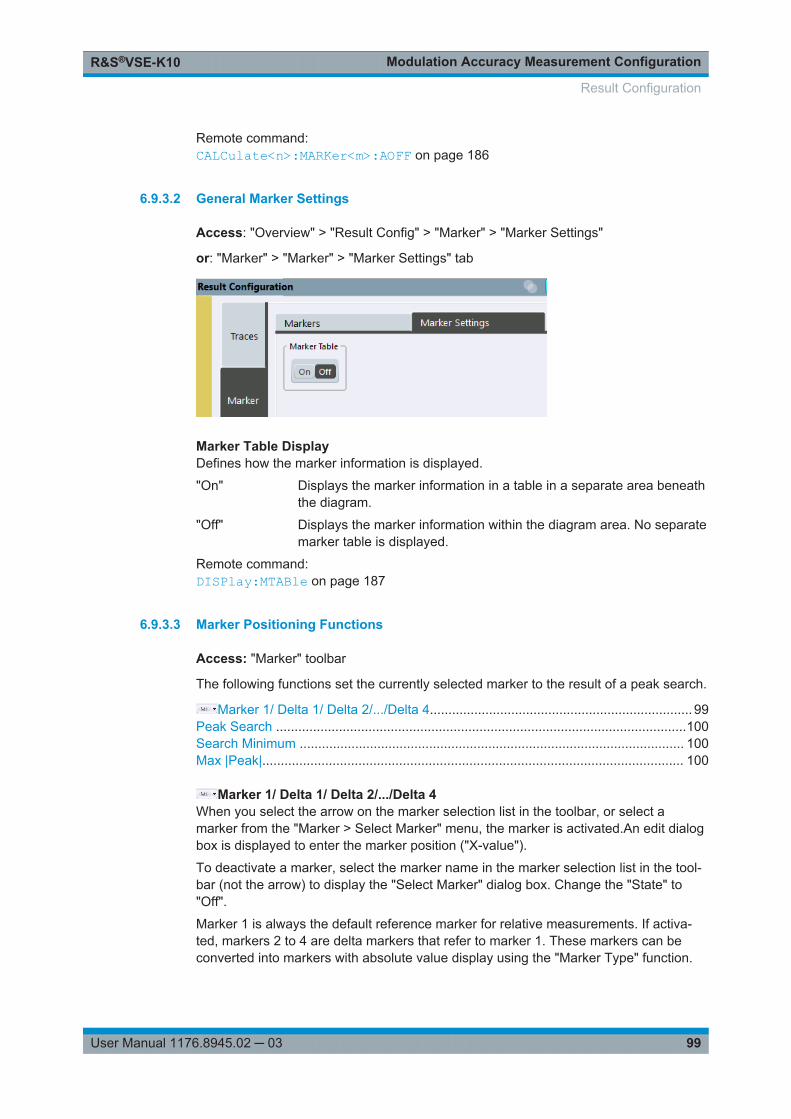
Modulation Accuracy Measurement ConfigurationR&S®VSE-K10
99User Manual 1176.8945.02 ─ 03
Remote command: CALCulate<n>:MARKer<m>:AOFF on page 186
6.9.3.2 General Marker Settings
Access: "Overview" > "Result Config" > "Marker" > "Marker Settings"
or: "Marker" > "Marker" > "Marker Settings" tab
Marker Table DisplayDefines how the marker information is displayed.
"On" Displays the marker information in a table in a separate area beneaththe diagram.
"Off" Displays the marker information within the diagram area. No separatemarker table is displayed.
Remote command: DISPlay:MTABle on page 187
6.9.3.3 Marker Positioning Functions
Access: "Marker" toolbar
The following functions set the currently selected marker to the result of a peak search.
Marker 1/ Delta 1/ Delta 2/.../Delta 4....................................................................... 99Peak Search ...............................................................................................................100Search Minimum ........................................................................................................ 100Max |Peak|.................................................................................................................. 100
Marker 1/ Delta 1/ Delta 2/.../Delta 4When you select the arrow on the marker selection list in the toolbar, or select amarker from the "Marker > Select Marker" menu, the marker is activated.An edit dialogbox is displayed to enter the marker position ("X-value").
To deactivate a marker, select the marker name in the marker selection list in the tool-bar (not the arrow) to display the "Select Marker" dialog box. Change the "State" to"Off".
Marker 1 is always the default reference marker for relative measurements. If activa-ted, markers 2 to 4 are delta markers that refer to marker 1. These markers can beconverted into markers with absolute value display using the "Marker Type" function.
Result Configuration
Modulation Accuracy Measurement ConfigurationR&S®VSE-K10
100User Manual 1176.8945.02 ─ 03
Remote command: CALCulate<n>:MARKer<m>[:STATe] on page 186CALCulate<n>:MARKer<m>:X on page 233CALCulate<n>:MARKer<m>:Y? on page 234CALCulate<n>:DELTamarker<m>[:STATe] on page 185CALCulate<n>:DELTamarker<m>:X on page 232CALCulate<n>:DELTamarker<m>:X:RELative? on page 232CALCulate<n>:DELTamarker<m>:Y? on page 233
Peak Search
Sets the selected marker/delta marker to the maximum of the trace. If no marker isactive, marker 1 is activated.
Remote command: CALCulate<n>:MARKer<m>:MAXimum[:PEAK] on page 188CALCulate<n>:DELTamarker<m>:MAXimum[:PEAK] on page 188
Search Minimum
Sets the selected marker/delta marker to the minimum of the trace. If no marker isactive, marker 1 is activated.
Remote command: CALCulate<n>:MARKer<m>:MINimum[:PEAK] on page 188CALCulate<n>:DELTamarker<m>:MINimum[:PEAK] on page 189
Max |Peak|
Sets the active marker/delta marker to the largest absolute peak value (maximum orminimum) of the selected trace.
Remote command: CALCulate<n>:MARKer<m>:MAXimum:APEak on page 187
6.9.4 Y-Axis Scaling
Access: "Overview" > "Result Config" > "Scaling"
or: "Input & Output" > "Scale"
The scaling for the vertical axis in (most) graphical displays is highly configurable,using either absolute or relative values. These settings are described here.
Result Configuration
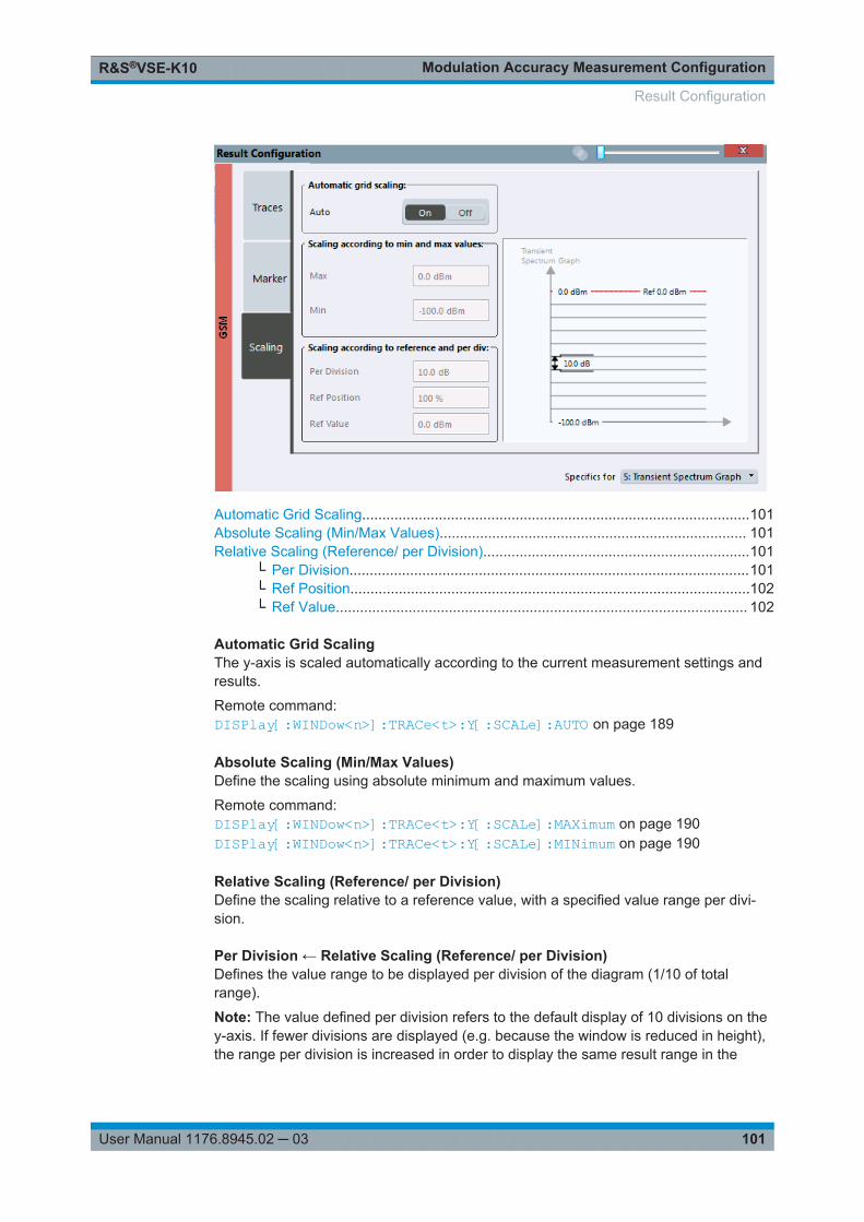
Modulation Accuracy Measurement ConfigurationR&S®VSE-K10
101User Manual 1176.8945.02 ─ 03
Automatic Grid Scaling................................................................................................101Absolute Scaling (Min/Max Values)............................................................................ 101Relative Scaling (Reference/ per Division)..................................................................101
└ Per Division...................................................................................................101└ Ref Position...................................................................................................102└ Ref Value...................................................................................................... 102
Automatic Grid ScalingThe y-axis is scaled automatically according to the current measurement settings andresults.
Remote command: DISPlay[:WINDow<n>]:TRACe<t>:Y[:SCALe]:AUTO on page 189
Absolute Scaling (Min/Max Values)Define the scaling using absolute minimum and maximum values.
Remote command: DISPlay[:WINDow<n>]:TRACe<t>:Y[:SCALe]:MAXimum on page 190DISPlay[:WINDow<n>]:TRACe<t>:Y[:SCALe]:MINimum on page 190
Relative Scaling (Reference/ per Division)Define the scaling relative to a reference value, with a specified value range per divi-sion.
Per Division ← Relative Scaling (Reference/ per Division)Defines the value range to be displayed per division of the diagram (1/10 of totalrange).
Note: The value defined per division refers to the default display of 10 divisions on they-axis. If fewer divisions are displayed (e.g. because the window is reduced in height),the range per division is increased in order to display the same result range in the
Result Configuration
Modulation Accuracy Measurement ConfigurationR&S®VSE-K10
102User Manual 1176.8945.02 ─ 03
smaller window. In this case, the per division value does not correspond to the actualdisplay.
Remote command: DISPlay[:WINDow<n>]:TRACe<t>:Y[:SCALe]:PDIVision on page 143
Ref Position ← Relative Scaling (Reference/ per Division)Defines the position of the reference value in percent of the total y-axis range.
Remote command: DISPlay[:WINDow<n>]:TRACe<t>:Y[:SCALe]:RPOSition on page 191
Ref Value ← Relative Scaling (Reference/ per Division)Defines the reference value to be displayed at the specified reference position.
Remote command: DISPlay[:WINDow<n>]:TRACe<t>:Y[:SCALe]:RVALue on page 191
Result Configuration
How to Perform Measurements in the GSM ApplicationR&S®VSE-K10
103User Manual 1176.8945.02 ─ 03
7 How to Perform Measurements in the GSMApplicationThe following step-by-step instructions demonstrate how to perform common GSMmeasurements with the R&S VSE GSM application.
● How to Perform a Basic Measurement on GSM Signals...................................... 103● How to Determine Modulation Accuracy Parameters for GSM Signals................ 104● How to Analyze the Power in GSM Signals.......................................................... 105● How to Analyze the Spectrum of GSM Signals.....................................................107
7.1 How to Perform a Basic Measurement on GSM Sig-nals
1. Open a new channel or replace an existing one and select the "GSM" application.
2. Select the "Meas Setup > Overview" menu item to display the "Overview" for aGSM measurement.
3. Select the "Signal Description" button and configure the expected signal by defin-ing the used device and slot characteristics as well as the modulation:
● Define the expected burst type and modulation for each active slot.● Define the training sequences (or syncs) with which each slot will be compared
to synchronize the measured data with the expected data.● For AQPSK modulated signals, define a TSC for each subchannel and each
active slot.● For access bursts, also define a "Timing Advance", i.e. the position of the
burst within the slot.● For signals from base stations capable of using multiple carriers, define addi-
tional settings on the "Multicarrier" tab.
4. Select the "Input/Frontend" button and then the "Frequency" tab to define the inputsignal's frequency band and center frequency.
5. Select the "Amplitude" tab in the "Input/Frontend" dialog box to define the correctpower class for the base station or mobile device.
6. Optionally, select the "Trigger" button and define a trigger for data acquisition, forexample an external trigger to start capturing data only when a useful signal istransmitted.
7. Optionally, to perform statistical evaluation over several measurements, switch tothe "Capture" tab in the "Data Acquisition" dialog box and define a "StatisticsCount".
How to Perform a Basic Measurement on GSM Signals
How to Perform Measurements in the GSM ApplicationR&S®VSE-K10
104User Manual 1176.8945.02 ─ 03
8. Select the "Demodulation" button to determine how bursts are detected anddemodulated.
9. Select the "Measurement" button and define the special measurement settings forthe Spectrum, Trigger to Sync and Power vs Time measurements.In particular, define the frequency list to be used to determine the modulation spec-trum, and filters to be used for multicarrier measurements.
10. Select the "Add Window" icon from the toolbar to add further result displays forthe GSM channel.
11. Select "Meas Setup > Overview" to display the "Overview".
12. Select the "Result Config" button to configure settings for specific result displays.These settings can be configured individually for each window, so select the win-dow first and then configure the settings.
● Define the "Traces" to be displayed in the window.Optionally, configure the trace to display the average over a series of measure-ments. If necessary, increase the "Statistics Count" in the "Capture" dialog box.
● Configure markers and delta markers to determine deviations and offsets withinthe results, e.g. when comparing errors or peaks.
● Adapt the diagram scaling to the displayed data.
13. In the "Control" toolbar, or in the "Sequence" tool window, select "Single" cap-ture mode, then select the "Capture" function to stop the continuous measure-ment mode and start a defined number of measurements.
7.2 How to Determine Modulation Accuracy Parametersfor GSM Signals
1. Open a new channel or replace an existing one and select the "GSM" application.
2. Select the "Meas Setup > Overview" menu item to display the "Overview" for aGSM measurement.
3. Select the "Signal Description" button and configure the expected signal by defin-ing the used device and slot characteristics as well as the modulation:
● Define the expected burst type and modulation for each active slot.● Define the training sequences (or syncs) with which each slot will be compared
to synchronize the measured data with the expected data.● For AQPSK modulated signals, define a TSC for each subchannel and each
active slot.● For access bursts, also define a "Timing Advance", i.e. the position of the
burst within the slot.● For signals from base stations capable of using multiple carriers, define addi-
tional settings on the "Multicarrier" tab.
How to Determine Modulation Accuracy Parameters for GSM Signals
How to Perform Measurements in the GSM ApplicationR&S®VSE-K10
105User Manual 1176.8945.02 ─ 03
4. Select the "Input/Frontend" button and then the "Frequency" tab to define the inputsignal's frequency band and center frequency.
5. Select the "Amplitude" tab in the "Input/Frontend" dialog box to define the correctpower class for the base station or mobile device.
6. Optionally, select the "Trigger" button and define a trigger for data acquisition, forexample an external trigger to start capturing data only when a useful signal istransmitted. For external triggers, do not forget to set the correct "Trigger Offset" tothe beginning of the GSM frame.
7. Optionally, to perform statistical evaluation over several measurements, switch tothe "Capture" tab in the "Data Acquisition" dialog box and define a "StatisticsCount".
8. Select the "Demodulation" button to determine how bursts are detected anddemodulated.
9. Select the "Add Window" icon from the toolbar to activate one or more of the fol-lowing result displays for modulation accuracy and error parameters:
● Modulation Accuracy● EVM● Magnitude Error● Phase Error
Tip: Also activate the Magnitude Capture result display for a general overview ofthe measured data.Arrange them on the display to suit your preferences.
10. In the "Control" toolbar, or in the "Sequence" tool window, select "Single" cap-ture mode, then select the "Capture" function to stop the continuous measure-ment mode and start a defined number of measurements.
11. Check the Magnitude Capture for irregular behavior, e.g. an unexpected rise or fallin power. If such an effect occurs, determine whether it occurred in the current slotscope and current slot to measure (compare the green and blue bars beneath thetrace). If necessary, zoom into the display to view it in greater detail.
12. If necessary, change the slot scope or slot to measure to display the slot of inter-est (e.g. using the softkeys in the "GSM" menu).
Now you can analyze the Magnitude Error, Phase Error, or EVM for that slot.
13. Compare the current results of the EVM with those of previous measurements tofind out if the error occurs only sporadically or repeatedly.
7.3 How to Analyze the Power in GSM Signals
1. Open a new channel or replace an existing one and select the "GSM" application.
How to Analyze the Power in GSM Signals
How to Perform Measurements in the GSM ApplicationR&S®VSE-K10
106User Manual 1176.8945.02 ─ 03
2. Select the "Meas Setup > Overview" menu item to display the "Overview" for aGSM measurement.
3. Select the "Signal Description" button and configure the expected signal by defin-ing the used device and slot characteristics as well as the modulation:
● Define the expected burst type and modulation for each active slot.● Define the training sequences (or syncs) with which each slot will be compared
to synchronize the measured data with the expected data.● For AQPSK modulated signals, define a TSC for each subchannel and each
active slot.● For access bursts, also define a "Timing Advance", i.e. the position of the
burst within the slot.● For signals from base stations capable of using multiple carriers, define addi-
tional settings on the "Multicarrier" tab.
4. Select the "Input/Frontend" button and then the "Frequency" tab to define the inputsignal's frequency band and center frequency.
5. Select the "Amplitude" tab in the "Input/Frontend" dialog box to define the correctpower class for the base station or mobile device.
6. Optionally, select the "Trigger" button and define a trigger for data acquisition, forexample an external trigger to start capturing data only when a useful signal istransmitted. For external triggers, do not forget to set the correct "Trigger Offset" tothe beginning of the GSM frame.
7. Optionally, to perform statistical evaluation over several measurements, switch tothe "Capture" tab in the "Data Acquisition" dialog box and define a "StatisticsCount".
8. Select the "Demodulation" button to determine how bursts are detected anddemodulated.
9. Select the "Measurement" button and define the special measurement settings forthe Power vs Time measurement:
● Define the PvT filter to be used (for selection criteria see Chapter 5.7.1, "Powervs Time Filter", on page 39).
● Define how the limit line defined by the standard is to be aligned to the mea-sured slots, and whether the relative positioning of the TSCs is measured orderived from the position of the specified Slot to Measure only.For measurements strictly according to standard, use the default "Limit LineTime Alignment": "Slot to Measure".For non-standard signals or signals with conspicuous slot timing, use the "PerSlot" setting.(Tip: use the "Delta to Sync" result of the Power vs Slot measurement to verifythe slot timing.)
10. Select the "Add Window" icon from the toolbar to select one or more of the fol-lowing displays for power results:
How to Analyze the Power in GSM Signals
How to Perform Measurements in the GSM ApplicationR&S®VSE-K10
107User Manual 1176.8945.02 ─ 03
● PvT Full Burst (power graph of all slots (bursts) in the selected slot scopeover time)
● Power vs Slot (table of power per slot in the current frame and over all frames)
Tip: Also display the Magnitude Capture for a general overview of the measureddata.Arrange them on the display to suit your preferences.
11. In the "Control" toolbar, or in the "Sequence" tool window, select "Single" cap-ture mode, then select the "Capture" function to stop the continuous measure-ment mode and start a defined number of measurements.
12. Check the PvT Full Burst results to determine if the signal remains within the limitsspecified by the standard in all slots to measure.
13. If the "Limit Check" indicates "FAIL", zoom into the Power vs Time graph to deter-mine the time at which the power exceeded the limit.Note: in measurements according to standard, the delta value will be identical forall slots in the scope due to the "Limit Line Time Alignment": "Slot to Measure" set-ting (see step 9).
14. Check the irregular slot in more detail in the Magnitude Capture (compare thegreen and blue bars beneath the trace). If necessary, zoom into the display to viewit in greater detail.
7.4 How to Analyze the Spectrum of GSM Signals
1. Open a new channel or replace an existing one and select the "GSM" application.
2. Select the "Meas Setup > Overview" menu item to display the "Overview" for aGSM measurement.
3. Select the "Signal Description" button and configure the expected signal by defin-ing the used device and slot characteristics as well as the modulation:
● Define the expected burst type and modulation for each active slot.● Define the training sequences (or syncs) with which each slot will be compared
to synchronize the measured data with the expected data.● For AQPSK modulated signals, define a TSC for each subchannel and each
active slot.● For access bursts, also define a "Timing Advance", i.e. the position of the
burst within the slot.● For signals from base stations capable of using multiple carriers, define addi-
tional settings on the "Multicarrier" tab.
4. Select the "Input/Frontend" button and then the "Frequency" tab to define the inputsignal's frequency band and center frequency.
How to Analyze the Spectrum of GSM Signals
How to Perform Measurements in the GSM ApplicationR&S®VSE-K10
108User Manual 1176.8945.02 ─ 03
5. Select the "Amplitude" tab in the "Input/Frontend" dialog box to define the correctpower class for the base station or mobile device.
6. Optionally, select the "Trigger" button and define a trigger for data acquisition, forexample an external trigger to start capturing data only when a useful signal istransmitted. For external triggers, do not forget to set the correct "Trigger Offset" tothe beginning of the GSM frame.
7. Optionally, to perform statistical evaluation over several measurements, switch tothe "Capture" tab in the "Data Acquisition" dialog box and define a "StatisticsCount".
8. Select the "Demodulation" button to determine how bursts are detected anddemodulated.
9. Select the "Measurement" button and define the special measurement settings forthe Spectrum measurements:
● For multicarrier base stations, define which carriers are measured:– the left-most carrier only ("Enable Left Limit" = ON)– the right-most carrier only ("Enable Right Limit" = ON)– all carriers ("Enable Left Limit" = ON, "Enable Right Limit" = ON)
● Select the type of resolution filter to be used.For measurements strictly according to standard, use the "Normal (3dB)" filter.
● Select the frequency list to be used to determine the modulation spectrum.For a quick overview, select a sparse list; for a conformance test, use the listspecified by the standardAs a rule, use the narrow list to test mobile devices, use the wide list for basestation tests.
● Select the reference power to be used to determine the relative limit values forthe transient spectrum.For measurements strictly according to standard, use the "RMS" setting.
10. Select the "Add Window" icon from the toolbar to select one or more of the fol-lowing displays for spectrum results:
● "Modulation Spectrum Graph" on page 17● "Modulation Spectrum Table" on page 18● "Transient Spectrum Graph" on page 24● "Transient Spectrum Table" on page 25
Tips:● Also display the Magnitude Capture for a general overview of the measured
data.● Use the graph displays for a general overview of the currently measured spec-
trum; the tables provide detailed numeric values, and an accurate conform-ance check of the DUT to the GSM standard.
● The modulation spectrum shows the spectrum for a portion of a burst in asingle slot (see "Modulation Spectrum Graph" on page 17); the transient spec-trum shows the spectrum for all slots in the slot scope, including the rising andfalling edges of the bursts.
How to Analyze the Spectrum of GSM Signals
How to Perform Measurements in the GSM ApplicationR&S®VSE-K10
109User Manual 1176.8945.02 ─ 03
Arrange the windows on the display to suit your preferences.
11. In the "Control" toolbar, or in the "Sequence" tool window, select "Single" cap-ture mode, then select the "Capture" function to stop the continuous measure-ment mode and start a defined number of measurements.
12. Check the result of the limit check in the graph. If it indicates "FAIL", refer to thenumeric results in the table display for more precise information on which fre-quency exceeds the limit (indicated by a negative "Δ to Limit" value and red char-acters).
How to Analyze the Spectrum of GSM Signals
Optimizing and Troubleshooting the MeasurementR&S®VSE-K10
110User Manual 1176.8945.02 ─ 03
8 Optimizing and Troubleshooting the Mea-surementIf the results of a GSM measurement do not meet your expectations, try the followingrecommendations to optimize the measurement.
● Improving Performance.........................................................................................110● Improving EVM Accuracy......................................................................................110● Optimizing Limit Checks........................................................................................111● Error Messages.....................................................................................................112
8.1 Improving Performance
If the GSM measurement seems to take a long time, try the following tips.
Using external triggers to mark the frame start
The R&S VSE GSM application needs the frame start as a time reference. It eithersearches for a frame start after every I/Q data acquisition, or relies on a trigger eventthat marks the frame start. An external trigger or a power trigger that mark the framestart can speed up measurements. See also Chapter 5.5, "Trigger settings",on page 35.
Avoiding unnecessary high sample rates
According to the GSM standard, modulation spectrum results must be performed atfrequencies up to 6 MHz from the carrier in some cases. When the frequency list to beused is set to 6 MHz in the "Measurement" settings (see "Modulation Spectrum Table:Frequency List" on page 90), the R&S VSE GSM application uses a sample rate of19.5 MHz, as opposed to the usual 6.5 MHz sample rate. The higher sample rateextends the required measurement time. Only use the 6 MHz frequency list setting ifyou actually require "Modulation Spectrum" results according to standard.
8.2 Improving EVM Accuracy
If the EVM results show unexpected power levels, check the following issues.
Extending the data basis
Sporadic distortions in the EVM can be eliminated by evaluating several measure-ments and determining the average over all traces. Increase the Statistic Count in the"Capture" settings to obtain sufficiently stable results.
Improving EVM Accuracy
Optimizing and Troubleshooting the MeasurementR&S®VSE-K10
111User Manual 1176.8945.02 ─ 03
Excluding results from adjacent channels
For signals from base stations capable of using multiple carriers, configure the DUTas such in the signal description. In this case, an additional multicarrier (PvT) filter sup-presses power from adjacent channels. This filter is also taken into account during thegeneration of the ideal (reference) signal, otherwise there would be an increase inEVM because the measured signal has a smaller bandwidth compared to the refer-ence signal. Define which PvT filter to use, depending on whether the channel to bemeasured has a reduced or equal power compared to its adjacent channels (see"Power vs Time Filter" on page 87).
For single carrier measurements, make sure the correct "Device Type" setting isselected so the correct PvT filter is used for the power measurement.
8.3 Optimizing Limit Checks
If the limit checks fail unexpectedly, check the following issues.
Excluding results from adjacent channels
In limit checks for multicarrier spectrum measurements, the frequencies from adja-cent carriers in the signal may distort the results of the limit check for a single carrier. Ifyou only want to check the frequencies from a single carrier in a multicarrier signal,disable the limit check for frequencies to the left or right of the carrier frequency ofinterest (see "Enable Left Limit/ Enable Right Limit" on page 89). This allows you tomeasure the spectrum of the left or right-most channel while ignoring the side whereadjacent channels are located.
Make sure you select the correct Slot to Measure for Modulation Spectrum results(see Chapter 6.6.1, "Slot Scope", on page 82).
Calculating limit lines according to the used DUT
For multicarrier measurements, ensure that the DUT is configured correctly (seeChapter 6.2.2, "Frame", on page 58). The number of active carriers and the specifiedBTS class affect the calculation of the limits according to the 3GPP standard for themodulation spectrum measurement.
Aligning the limit line correctly
The limit line defined by the standard must be aligned to the measured slots. The align-ment can either be determined individually for each slot, or the entire line is alignedaccording to the Slot to Measure (see "Limit Line Time Alignment" on page 88).
The standard requires that the entire line be aligned according to the Slot to Measure.However, in this case the "Delta to Sync" value will be identical for all slots in the scope(see Table 4-7).
Note that the R&S VSE GSM application assumes that all slots have equal length. Ifthey do not, disable this setting in the "Frame" settings (see "Equal Timeslot Length"on page 59) so the limit line is aligned to the slots correctly.
Optimizing Limit Checks
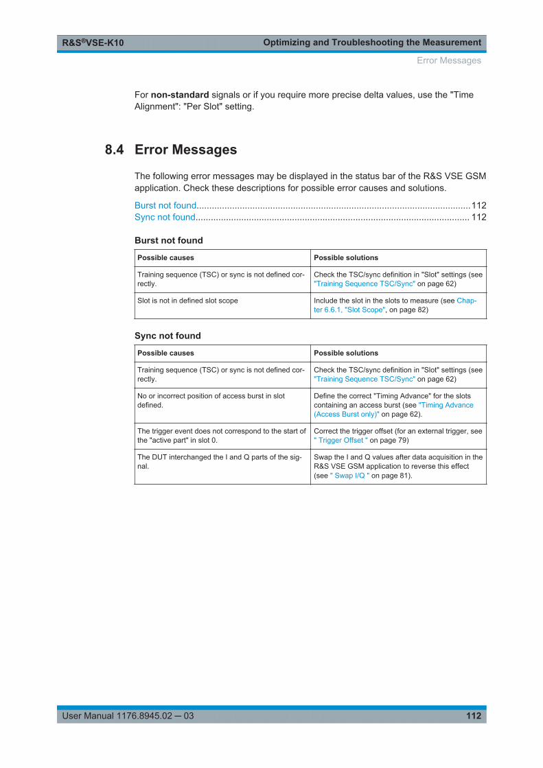
Optimizing and Troubleshooting the MeasurementR&S®VSE-K10
112User Manual 1176.8945.02 ─ 03
For non-standard signals or if you require more precise delta values, use the "TimeAlignment": "Per Slot" setting.
8.4 Error Messages
The following error messages may be displayed in the status bar of the R&S VSE GSMapplication. Check these descriptions for possible error causes and solutions.
Burst not found............................................................................................................112Sync not found............................................................................................................ 112
Burst not found
Possible causes Possible solutions
Training sequence (TSC) or sync is not defined cor-rectly.
Check the TSC/sync definition in "Slot" settings (see"Training Sequence TSC/Sync" on page 62)
Slot is not in defined slot scope Include the slot in the slots to measure (see Chap-ter 6.6.1, "Slot Scope", on page 82)
Sync not found
Possible causes Possible solutions
Training sequence (TSC) or sync is not defined cor-rectly.
Check the TSC/sync definition in "Slot" settings (see"Training Sequence TSC/Sync" on page 62)
No or incorrect position of access burst in slotdefined.
Define the correct "Timing Advance" for the slotscontaining an access burst (see "Timing Advance(Access Burst only)" on page 62).
The trigger event does not correspond to the start ofthe "active part" in slot 0.
Correct the trigger offset (for an external trigger, see" Trigger Offset " on page 79)
The DUT interchanged the I and Q parts of the sig-nal.
Swap the I and Q values after data acquisition in theR&S VSE GSM application to reverse this effect(see " Swap I/Q " on page 81).
Error Messages
Remote Commands to Perform GSM MeasurementsR&S®VSE-K10
113User Manual 1176.8945.02 ─ 03
9 Remote Commands to Perform GSM Mea-surementsThe following commands are required to perform measurements in the R&S VSE GSMapplication in a remote environment.
It is assumed that the R&S VSE has already been set up for remote control in a net-work as described in the R&S VSE Base Software User Manual.
General R&S VSE Remote Commands
The application-independent remote commands for general tasks on the R&S VSE arealso available for GSM measurements and are described in the R&S VSE User Man-ual. In particular, this comprises the following functionality:● Controlling instruments and capturing data● Managing Settings and Results● Setting Up the Instrument● Using the Status Register
Channel-specific commands
Apart from a few general commands on the R&S VSE, most commands refer to thecurrently active channel. Thus, always remember to activate a GSM channel beforestarting a remote program for a GSM measurement.
After a short introduction, the tasks specific to the GSM application are described here:
● Introduction........................................................................................................... 113● Common Suffixes..................................................................................................118● Activating GSM Measurements.............................................................................119● Restoring the Default Configuration (Preset)........................................................ 119● Configuring and Performing GSM I/Q Measurements.......................................... 119● Analyzing GSM Measurements.............................................................................169● Retrieving Results.................................................................................................194● Status Reporting System...................................................................................... 234● Deprecated Commands........................................................................................ 239● Programming Examples........................................................................................247
9.1 Introduction
Commands are program messages that a controller (e.g. a PC) sends to the instru-ment or software. They operate its functions ('setting commands' or 'events') andrequest information ('query commands'). Some commands can only be used in oneway, others work in two ways (setting and query). If not indicated otherwise, the com-mands can be used for settings and queries.
Introduction
Remote Commands to Perform GSM MeasurementsR&S®VSE-K10
114User Manual 1176.8945.02 ─ 03
The syntax of a SCPI command consists of a header and, in most cases, one or moreparameters. To use a command as a query, you have to append a question mark afterthe last header element, even if the command contains a parameter.
A header contains one or more keywords, separated by a colon. Header and parame-ters are separated by a "white space" (ASCII code 0 to 9, 11 to 32 decimal, e.g. blank).If there is more than one parameter for a command, these are separated by a commafrom one another.
Only the most important characteristics that you need to know when working with SCPIcommands are described here. For a more complete description, refer to the UserManual of the R&S VSE.
Remote command examplesNote that some remote command examples mentioned in this general introduction maynot be supported by this particular application.
9.1.1 Conventions used in Descriptions
Note the following conventions used in the remote command descriptions:● Command usage
If not specified otherwise, commands can be used both for setting and for queryingparameters.If a command can be used for setting or querying only, or if it initiates an event, theusage is stated explicitly.
● Parameter usageIf not specified otherwise, a parameter can be used to set a value and it is theresult of a query.Parameters required only for setting are indicated as Setting parameters.Parameters required only to refine a query are indicated as Query parameters.Parameters that are only returned as the result of a query are indicated as Returnvalues.
● ConformityCommands that are taken from the SCPI standard are indicated as SCPI con-firmed. All commands used by the R&S VSE follow the SCPI syntax rules.
● Asynchronous commandsA command which does not automatically finish executing before the next com-mand starts executing (overlapping command) is indicated as an Asynchronouscommand.
● Reset values (*RST)Default parameter values that are used directly after resetting the instrument (*RSTcommand) are indicated as *RST values, if available.
● Default unitThis is the unit used for numeric values if no other unit is provided with the parame-ter.
● Manual operation
Introduction
Remote Commands to Perform GSM MeasurementsR&S®VSE-K10
115User Manual 1176.8945.02 ─ 03
If the result of a remote command can also be achieved in manual operation, a linkto the description is inserted.
9.1.2 Long and Short Form
The keywords have a long and a short form. You can use either the long or the shortform, but no other abbreviations of the keywords.
The short form is emphasized in upper case letters. Note however, that this emphasisonly serves the purpose to distinguish the short from the long form in the manual. Forthe instrument, the case does not matter.
Example: SENSe:FREQuency:CENTer is the same as SENS:FREQ:CENT.
9.1.3 Numeric Suffixes
Some keywords have a numeric suffix if the command can be applied to multipleinstances of an object. In that case, the suffix selects a particular instance (e.g. a mea-surement window).
Numeric suffixes are indicated by angular brackets (<n>) next to the keyword.
If you don't quote a suffix for keywords that support one, a 1 is assumed.
Example: DISPlay[:WINDow<1...4>]:ZOOM:STATe enables the zoom in a particular mea-surement window, selected by the suffix at WINDow.
DISPlay:WINDow4:ZOOM:STATe ON refers to window 4.
9.1.4 Optional Keywords
Some keywords are optional and are only part of the syntax because of SCPI compli-ance. You can include them in the header or not.
Note that if an optional keyword has a numeric suffix and you need to use the suffix,you have to include the optional keyword. Otherwise, the suffix of the missing keywordis assumed to be the value 1.
Optional keywords are emphasized with square brackets.
Introduction
Remote Commands to Perform GSM MeasurementsR&S®VSE-K10
116User Manual 1176.8945.02 ─ 03
Example: Without a numeric suffix in the optional keyword:[SENSe:]FREQuency:CENTer is the same as FREQuency:CENTerWith a numeric suffix in the optional keyword:DISPlay[:WINDow<1...4>]:ZOOM:STATeDISPlay:ZOOM:STATe ON enables the zoom in window 1 (no suffix).
DISPlay:WINDow4:ZOOM:STATe ON enables the zoom in window 4.
9.1.5 Alternative Keywords
A vertical stroke indicates alternatives for a specific keyword. You can use both key-words to the same effect.
Example: [SENSe:]BANDwidth|BWIDth[:RESolution]In the short form without optional keywords, BAND 1MHZ would have the same effectas BWID 1MHZ.
9.1.6 SCPI Parameters
Many commands feature one or more parameters.
If a command supports more than one parameter, these are separated by a comma.
Example: LAYout:ADD:WINDow Spectrum,LEFT,MTABle
Parameters may have different forms of values.
● Numeric Values.....................................................................................................116● Boolean.................................................................................................................117● Character Data......................................................................................................118● Character Strings.................................................................................................. 118● Block Data.............................................................................................................118
9.1.6.1 Numeric Values
Numeric values can be entered in any form, i.e. with sign, decimal point or exponent. Incase of physical quantities, you can also add the unit. If the unit is missing, the com-mand uses the basic unit.
Example: With unit: SENSe:FREQuency:CENTer 1GHZWithout unit: SENSe:FREQuency:CENTer 1E9 would also set a frequency of 1 GHz.
Introduction
Remote Commands to Perform GSM MeasurementsR&S®VSE-K10
117User Manual 1176.8945.02 ─ 03
Values exceeding the resolution of the instrument are rounded up or down.
If the number you have entered is not supported (e.g. in case of discrete steps), thecommand returns an error.
Instead of a number, you can also set numeric values with a text parameter in specialcases.
● MIN/MAXDefines the minimum or maximum numeric value that is supported.
● DEFDefines the default value.
● UP/DOWNIncreases or decreases the numeric value by one step. The step size depends onthe setting. In some cases you can customize the step size with a correspondingcommand.
Querying numeric values
When you query numeric values, the system returns a number. In case of physicalquantities, it applies the basic unit (e.g. Hz in case of frequencies). The number of dig-its after the decimal point depends on the type of numeric value.
Example: Setting: SENSe:FREQuency:CENTer 1GHZQuery: SENSe:FREQuency:CENTer? would return 1E9
In some cases, numeric values may be returned as text.
● INF/NINFInfinity or negative infinity. Represents the numeric values 9.9E37 or -9.9E37.
● NANNot a number. Represents the numeric value 9.91E37. NAN is returned in case oferrors.
9.1.6.2 Boolean
Boolean parameters represent two states. The "ON" state (logically true) is represen-ted by "ON" or a numeric value 1. The "OFF" state (logically untrue) is represented by"OFF" or the numeric value 0.
Querying Boolean parameters
When you query Boolean parameters, the system returns either the value 1 ("ON") orthe value 0 ("OFF").
Example: Setting: DISPlay:WINDow:ZOOM:STATe ONQuery: DISPlay:WINDow:ZOOM:STATe? would return 1
Introduction
Remote Commands to Perform GSM MeasurementsR&S®VSE-K10
118User Manual 1176.8945.02 ─ 03
9.1.6.3 Character Data
Character data follows the syntactic rules of keywords. You can enter text using a shortor a long form. For more information see Chapter 9.1.2, "Long and Short Form",on page 115.
Querying text parameters
When you query text parameters, the system returns its short form.
Example: Setting: SENSe:BANDwidth:RESolution:TYPE NORMalQuery: SENSe:BANDwidth:RESolution:TYPE? would return NORM
9.1.6.4 Character Strings
Strings are alphanumeric characters. They have to be in straight quotation marks. Youcan use a single quotation mark ( ' ) or a double quotation mark ( " ).
Example: INSTRument:DELete 'Spectrum'
9.1.6.5 Block Data
Block data is a format which is suitable for the transmission of large amounts of data.
The ASCII character # introduces the data block. The next number indicates how manyof the following digits describe the length of the data block. In the example the 4 follow-ing digits indicate the length to be 5168 bytes. The data bytes follow. During the trans-mission of these data bytes all end or other control signs are ignored until all bytes aretransmitted. #0 specifies a data block of indefinite length. The use of the indefinite for-mat requires an NL^END message to terminate the data block. This format is usefulwhen the length of the transmission is not known or if speed or other considerationsprevent segmentation of the data into blocks of definite length.
9.2 Common Suffixes
In the R&S VSE GSM application, the following common suffixes are used in remotecommands:
Table 9-1: Common suffixes used in remote commands in the R&S VSE GSM application
Suffix Value range Description
<m> 1 to 4 Marker
<n> 1 to x Window (in the currently selected channel)
Common Suffixes
Remote Commands to Perform GSM MeasurementsR&S®VSE-K10
119User Manual 1176.8945.02 ─ 03
Suffix Value range Description
<t> 1 to 4 Trace
<k> not applicable Limit line
9.3 Activating GSM Measurements
GSM measurements require a special application in the R&S VSE. The common com-mands for configuring and controlling measurement channels, as well as blocks andsequences, are also used in the R&S VSE GSM application.
They are described in the R&S VSE Base Software User Manual.
9.4 Restoring the Default Configuration (Preset)
SYSTem:PRESet:CHANnel[:EXEC].................................................................................119
SYSTem:PRESet:CHANnel[:EXEC]
This command restores the default software settings in the current channel.
Use INST:SEL to select the channel.
Example: INST:SEL 'Spectrum2'Selects the channel for "Spectrum2".SYST:PRES:CHAN:EXECRestores the factory default settings to the "Spectrum2" channel.
Usage: Event
Manual operation: See "Preset Channel" on page 56
9.5 Configuring and Performing GSM I/Q Measurements
The following commands are required to configure a default GSM I/Q (ModulationAccuracy...) measurement on an R&S VSE in a remote environment.
● Signal Description................................................................................................. 120● Configuring Data Input.......................................................................................... 134● Frontend Configuration......................................................................................... 141● Triggering Measurements..................................................................................... 147● Data Acquisition.................................................................................................... 154● Demodulation........................................................................................................157● Measurement........................................................................................................ 162● Adjusting Settings Automatically...........................................................................168
Configuring and Performing GSM I/Q Measurements
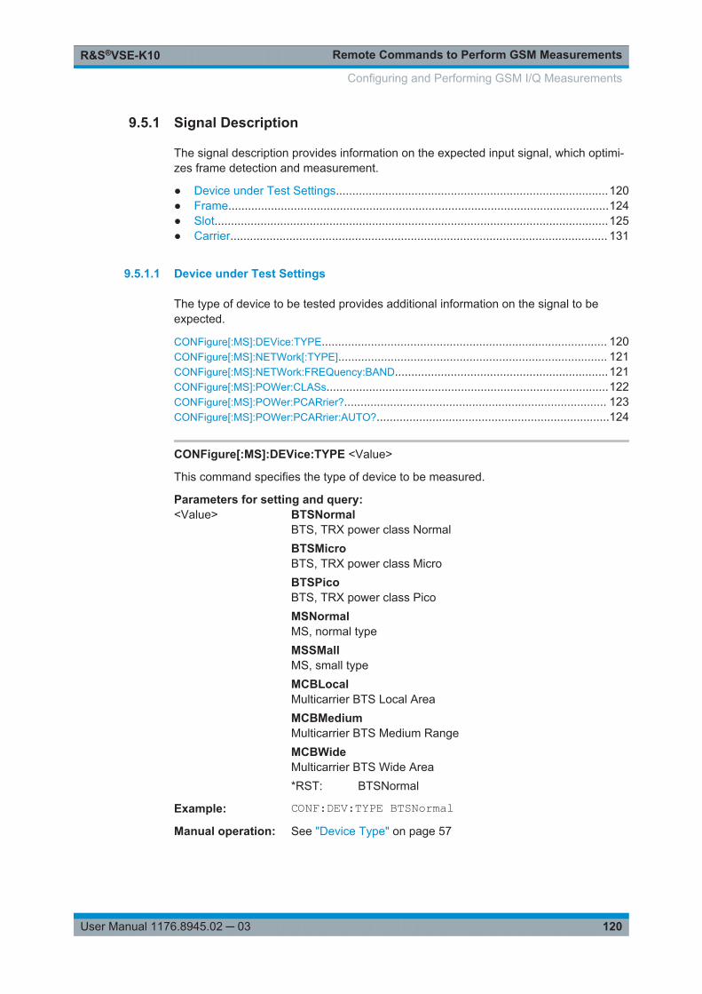
Remote Commands to Perform GSM MeasurementsR&S®VSE-K10
120User Manual 1176.8945.02 ─ 03
9.5.1 Signal Description
The signal description provides information on the expected input signal, which optimi-zes frame detection and measurement.
● Device under Test Settings...................................................................................120● Frame....................................................................................................................124● Slot........................................................................................................................125● Carrier................................................................................................................... 131
9.5.1.1 Device under Test Settings
The type of device to be tested provides additional information on the signal to beexpected.
CONFigure[:MS]:DEVice:TYPE....................................................................................... 120CONFigure[:MS]:NETWork[:TYPE].................................................................................. 121CONFigure[:MS]:NETWork:FREQuency:BAND.................................................................121CONFigure[:MS]:POWer:CLASs......................................................................................122CONFigure[:MS]:POWer:PCARrier?................................................................................ 123CONFigure[:MS]:POWer:PCARrier:AUTO?.......................................................................124
CONFigure[:MS]:DEVice:TYPE <Value>
This command specifies the type of device to be measured.
Parameters for setting and query: <Value> BTSNormal
BTS, TRX power class NormalBTSMicroBTS, TRX power class MicroBTSPicoBTS, TRX power class PicoMSNormalMS, normal typeMSSMallMS, small typeMCBLocalMulticarrier BTS Local AreaMCBMediumMulticarrier BTS Medium RangeMCBWideMulticarrier BTS Wide Area*RST: BTSNormal
Example: CONF:DEV:TYPE BTSNormalManual operation: See "Device Type" on page 57
Configuring and Performing GSM I/Q Measurements
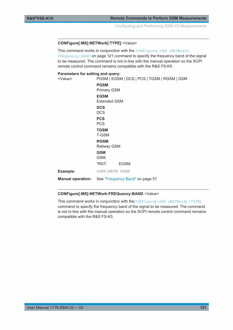
Remote Commands to Perform GSM MeasurementsR&S®VSE-K10
121User Manual 1176.8945.02 ─ 03
CONFigure[:MS]:NETWork[:TYPE] <Value>
This command works in conjunction with the CONFigure[:MS]:NETWork:FREQuency:BAND on page 121 command to specify the frequency band of the signalto be measured. The command is not in-line with the manual operation so the SCPIremote control command remains compatible with the R&S FS-K5.
Parameters for setting and query: <Value> PGSM | EGSM | DCS | PCS | TGSM | RGSM | GSM
PGSMPrimary GSMEGSMExtended GSMDCSDCSPCSPCSTGSMT-GSMRGSMRailway GSMGSMGSM*RST: EGSM
Example: CONF:NETW PGSMManual operation: See "Frequency Band" on page 57
CONFigure[:MS]:NETWork:FREQuency:BAND <Value>
This command works in conjunction with theCONFigure[:MS]:NETWork[:TYPE]command to specify the frequency band of the signal to be measured. The commandis not in-line with the manual operation so the SCPI remote control command remainscompatible with the R&S FS-K5.
Configuring and Performing GSM I/Q Measurements
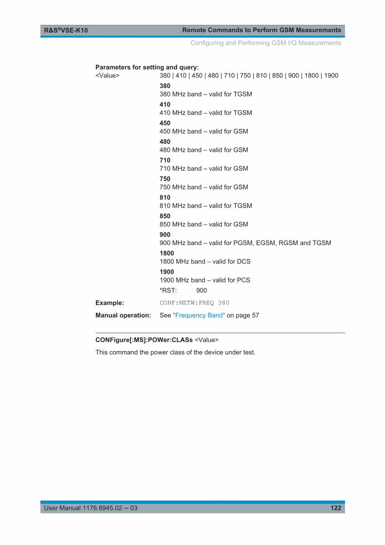
Remote Commands to Perform GSM MeasurementsR&S®VSE-K10
122User Manual 1176.8945.02 ─ 03
Parameters for setting and query: <Value> 380 | 410 | 450 | 480 | 710 | 750 | 810 | 850 | 900 | 1800 | 1900
380380 MHz band – valid for TGSM410410 MHz band – valid for TGSM450450 MHz band – valid for GSM480480 MHz band – valid for GSM710710 MHz band – valid for GSM750750 MHz band – valid for GSM810810 MHz band – valid for TGSM850850 MHz band – valid for GSM900900 MHz band – valid for PGSM, EGSM, RGSM and TGSM18001800 MHz band – valid for DCS19001900 MHz band – valid for PCS*RST: 900
Example: CONF:NETW:FREQ 380Manual operation: See "Frequency Band" on page 57
CONFigure[:MS]:POWer:CLASs <Value>
This command the power class of the device under test.
Configuring and Performing GSM I/Q Measurements
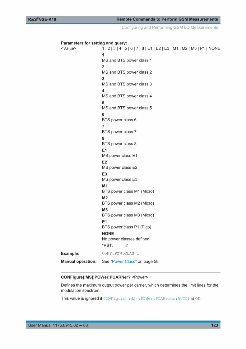
Remote Commands to Perform GSM MeasurementsR&S®VSE-K10
123User Manual 1176.8945.02 ─ 03
Parameters for setting and query: <Value> 1 | 2 | 3 | 4 | 5 | 6 | 7 | 8 | E1 | E2 | E3 | M1 | M2 | M3 | P1 | NONE
1MS and BTS power class 12MS and BTS power class 23MS and BTS power class 34MS and BTS power class 45MS and BTS power class 56BTS power class 67BTS power class 78BTS power class 8E1MS power class E1E2MS power class E2E3MS power class E3M1BTS power class M1 (Micro)M2BTS power class M2 (Micro)M3BTS power class M3 (Micro)P1BTS power class P1 (Pico)NONENo power classes defined*RST: 2
Example: CONF:POW:CLAS 1Manual operation: See "Power Class" on page 58
CONFigure[:MS]:POWer:PCARrier? <Power>
Defines the maximum output power per carrier, which determines the limit lines for themodulation spectrum.
This value is ignored if CONFigure[:MS]:POWer:PCARrier:AUTO? is ON.
Configuring and Performing GSM I/Q Measurements
Remote Commands to Perform GSM MeasurementsR&S®VSE-K10
124User Manual 1176.8945.02 ─ 03
Parameters:<Power> maximum output power in dBm
*RST: 0 dBm
Example: CONF:POW:PCAR:AUTO OFFCONF:POW:PCAR 4 dBm
Usage: Query only
Manual operation: See "Maximum Output Power per Carrier (multicarrier measure-ments only)" on page 58
CONFigure[:MS]:POWer:PCARrier:AUTO? <State>
If enabled, the maximum measured power level for the carriers is used as the maxi-mum output power per carrier.
If disabled, the maximum power is defined by CONFigure[:MS]:POWer:PCARrier?on page 123.
Parameters:<State> ON | OFF | 1 | 0
*RST: 1
Example: CONF:POW:PCAR:AUTO OFFCONF:POW:PCAR 4 dBm
Usage: Query only
Manual operation: See "Maximum Output Power per Carrier (multicarrier measure-ments only)" on page 58
9.5.1.2 Frame
Frame settings determine the frame configuration used by the device under test.
CONFigure[:MS]:CHANnel:FRAMe:EQUal........................................................................124
CONFigure[:MS]:CHANnel:FRAMe:EQUal <State>
If activated, all slots of a frame have the same length (8 x 156.26 normal symbol peri-ods).
If deactivated, slots number 0 and 4 of a frame have a longer duration, all other ashorter duration compared to the "equal slot length" (157, 156, 156, 156, 157, 156,156, 156 normal symbol periods).
See 3GPP TS 51.0213GPP TS 51.021 and 3GPP TS 45.0103GPP TS 45.010 chapter"6.7 Timeslot length" for further details.
This parameter is used to adjust the time for the "Power vs Time" masks of all slots.The "Slot to measure" is used as the time reference for the entire frame.
Configuring and Performing GSM I/Q Measurements
Remote Commands to Perform GSM MeasurementsR&S®VSE-K10
125User Manual 1176.8945.02 ─ 03
Parameters for setting and query: <State> 1 | 0 | ON | OFF
*RST: 1
Example: CONF:CHAN:FRAM:EQU OFFManual operation: See "Equal Timeslot Length" on page 59
For a detailed example see Chapter 9.10.1, "Programming Example: Determining theEVM", on page 248.
9.5.1.3 Slot
The R&S VSE GSM application is slot-based. Thus, information on the expected slotsof the input signal are required. The following commands are required to provide thisinformation.
CONFigure[:MS]:CHANnel:SLOT<Number>:FILTer...........................................................125CONFigure[:MS]:CHANnel:SLOT<Number>[:STATe]........................................................ 126CONFigure[:MS]:CHANnel:SLOT<Number>:MTYPe..........................................................126CONFigure[:MS]:CHANnel:SLOT<s>:SCPir......................................................................127CONFigure[:MS]:CHANnel:SLOT<s>:SUBChannel<ch>:TSC:USER................................... 127CONFigure[:MS]:CHANnel:SLOT<s>:SUBChannel<ch>:TSC.............................................128CONFigure[:MS]:CHANnel:SLOT<Number>:TADVance.....................................................128CONFigure[:MS]:CHANnel:SLOT<s>:TSC........................................................................129CONFigure[:MS]:CHANnel:SLOT<s>:TSC:USER..............................................................130CONFigure[:MS]:CHANnel:SLOT<Number>:TYPE............................................................131
CONFigure[:MS]:CHANnel:SLOT<Number>:FILTer <Type>
This command specifies the pulse shape of the ideal modulator.
Suffix: <Number>
.<0..7>the slot to configure
Parameters for setting and query: <Type> GMSK | LINearised | NARRow | WIDE
GMSKGMSK PulseLINearisedLinearised GMSK PulseNARRowNarrow PulseWIDEWide Pulse*RST: GMSK
Example: CONF:CHAN:SLOT:FILT GMSKManual operation: See "Filter" on page 62
Configuring and Performing GSM I/Q Measurements
Remote Commands to Perform GSM MeasurementsR&S®VSE-K10
126User Manual 1176.8945.02 ─ 03
For a detailed example see Chapter 9.10.1, "Programming Example: Determining theEVM", on page 248.
CONFigure[:MS]:CHANnel:SLOT<Number>[:STATe] <State>
This command activates this slot (this means that e.g. this slot is not considered asinactive in the PvT evaluation).
Suffix: <Number>
.<0..7>Select the slot to configure.
Parameters for setting and query: <State> ON | OFF | 1 | 0
Example: CONF:CHAN:SLOT ONManual operation: See "Slot State (On/Off)" on page 61
For a detailed example see Chapter 9.10.1, "Programming Example: Determining theEVM", on page 248 or Chapter 9.10.2, "Programming Example: Measuring an AQPSKSignal", on page 252.
CONFigure[:MS]:CHANnel:SLOT<Number>:MTYPe <Modulation>
This command specifies the modulation type.
Suffix: <Number>
.<0..7>the slot to configure
Parameters for setting and query: <Modulation> GMSK
GMSK, Gaussian Minimum Shift Keying, 1 bit/symbol.QPSKQPSK, Quadrature Phase Shift keying, 2 bits/symbol.PSK88PSK (EDGE), Phase Shift Keying, 3 bits/symbol.QAM1616QAM, 16-ary Quadrature Amplitude Modulation, 4 bits/symbol.QAM3232QAM, 16-ary Quadrature Amplitude Modulation, 5 bits/symbol.*RST: GMSK
Example: CONF:CHAN:SLOT0:MTYP GMSKManual operation: See "Modulation" on page 62
For a detailed example see Chapter 9.10.1, "Programming Example: Determining theEVM", on page 248 or Chapter 9.10.2, "Programming Example: Measuring an AQPSKSignal", on page 252.
Configuring and Performing GSM I/Q Measurements
Remote Commands to Perform GSM MeasurementsR&S®VSE-K10
127User Manual 1176.8945.02 ─ 03
CONFigure[:MS]:CHANnel:SLOT<s>:SCPir <Value>
This command specifies the Subchannel Power Imbalance Ratio (SCPIR) of the speci-fied slot.
Notes:
This command is only available for AQPSK modulation.
Suffix: <s>
.<0..7>Number of slot to configure
Parameters for setting and query: <Value> numeric value
Subchannel Power Imbalance Ratio (SCPIR) in dBRange: -15 to 15*RST: 0Default unit: NONE
Example: // Subchannel Power Imbalance Ratio (SCPIR) = 4 dBCONFigure:MS:CHANnel:SLOT0:SCPir 4
Manual operation: See "SCPIR" on page 62
For a detailed example see Chapter 9.10.2, "Programming Example: Measuring anAQPSK Signal", on page 252 or Chapter 9.10.2, "Programming Example: Measuringan AQPSK Signal", on page 252.
CONFigure[:MS]:CHANnel:SLOT<s>:SUBChannel<ch>:TSC:USER <Value>
This command sets the bits of the user definable TSC. The number of bits must be 26.CONFigure[:MS]:CHANnel:SLOT<s>:SUBChannel<ch>:TSC:USER must be setfirst.
This command is only available for AQPSK modulation.
Suffix: <s>
.<0..7>Number of slot to configure
<ch> <1|2>Subchannel number
Parameters for setting and query: <Value> string
String containing the 26 user-defined bits
Example: // Subchannel 1: User TSCCONFigure:MS:CHANnel:SLOT0:SUBChannel1:TSC USERCONFigure:MS:CHANnel:SLOT0:SUBChannel1:TSC?// -> USER
Manual operation: See "User TSC/User Sync " on page 63
Configuring and Performing GSM I/Q Measurements
Remote Commands to Perform GSM MeasurementsR&S®VSE-K10
128User Manual 1176.8945.02 ─ 03
For a detailed example see Chapter 9.10.2, "Programming Example: Measuring anAQPSK Signal", on page 252 or Chapter 9.10.2, "Programming Example: Measuringan AQPSK Signal", on page 252.
CONFigure[:MS]:CHANnel:SLOT<s>:SUBChannel<ch>:TSC <Value>
This command selects the training sequence of the specified slot and subchannel usedby the mobile or base station.
This command is only available for AQPSK modulation.
Suffix: <s>
.<0..7>Number of slot to configure
<ch> <1|2>Subchannel number
Query parameters: <ResultType> TSC | SET
Queries the currently used TSC number or the set.
Parameters for setting and query: <Value> 0,1 | 0,2 | 1,1 | 1,2 | 2,1 | 2,2 | 3,1 | 3,2 | 4,1 | 4,2 | 5,1 | 5,2 | 6,1 |
6,2 | 7,1 | 7,2 | USERTSC number and Set or User TSCSet 2 is only available for subchannel 2.*RST: 0,1
Example: // Subchannel 1: TSC 0 (Set 1)CONFigure:MS:CHANnel:SLOT0:SUBChannel1:TSC 0,1// Subchannel 1: Query TSC number and Set numberCONFigure:MS:CHANnel:SLOT0:SUBChannel1:TSC?// -> 0,1// Subchannel 1: Query TSC numberCONFigure:MS:CHANnel:SLOT0:SUBChannel1:TSC? TSC// -> 0// Subchannel 1: Query Set numberCONFigure:MS:CHANnel:SLOT0:SUBChannel1:TSC? SET// -> 1
Manual operation: See "Training Sequence TSC/Sync" on page 62
For a detailed example see Chapter 9.10.2, "Programming Example: Measuring anAQPSK Signal", on page 252 or Chapter 9.10.2, "Programming Example: Measuringan AQPSK Signal", on page 252.
CONFigure[:MS]:CHANnel:SLOT<Number>:TADVance <Offset>
Specifies the position of an access burst within a single slot.
This command is only available for access bursts (see CONFigure[:MS]:CHANnel:SLOT<Number>:TYPE on page 131).
Configuring and Performing GSM I/Q Measurements
Remote Commands to Perform GSM MeasurementsR&S®VSE-K10
129User Manual 1176.8945.02 ─ 03
Suffix: <Number>
.<0..7>
Parameters for setting and query: <Offset> offset from slot start in symbols
Range: 0 to 63Increment: 10*RST: 0
Example: CONF:CHAN:SLOT:TADV 1Manual operation: See "Timing Advance (Access Burst only)" on page 62
CONFigure[:MS]:CHANnel:SLOT<s>:TSC <Value>
This command selects the training sequence code TSC (Normal and Higher SymbolRate Bursts) or training (synchronization) sequence TS (for Access Bursts) of thespecified slot and subchannel used by the mobile or base station. See 3GPP TS45.002, chapter 5.2 'Bursts'.
This command is not available for AQPSK modulation (use CONFigure[:MS]:CHANnel:SLOT<s>:TSC instead).
Suffix: <s>
.0..7Number of the slot to configure
Query parameters: <ResultType> TSC | SET
Queries the currently used TSC number or the set.If no query parameter is defined, only the TS or the TSC isreturned.TSCOnly the TSC or TS is returned.SETThe set of the TSC is returned.
Configuring and Performing GSM I/Q Measurements
Remote Commands to Perform GSM MeasurementsR&S®VSE-K10
130User Manual 1176.8945.02 ─ 03
Parameters for setting and query: <Value> 0 | 1 | 2 | 3 | 4 | 5 | 6 | 7 | 0,1 | 0,2 | 1,1 | 1,2 | 2,1 | 2,2 | 3,1 | 3,2 |
4,1 | 4,2 | 5,1 | 5,2 | 6,1 | 6,2 | 7,1 | 7,2 | TS0 | TS1 | TS2 | USERtraining sequence for normal burst0...7One of the 7 pre-defined training sequence codes is used0,1 | 0,2 | 1,1 | 1,2 | 2,1 | 2,2 | 3,1 | 3,2 | 4,1 | 4,2 | 5,1 | 5,2 | 6,1| 6,2 | 7,1 | 7,2TSC number and set for normal burst ratesTS0 | TS1 | TS2Training (synchronization) sequence for access burstsUSERA user-defined training sequence is used (see CONFigure[:MS]:CHANnel:SLOT<s>:TSC:USER on page 130).
*RST: 0
Example: // TSC 3 (Set 1)CONFigure:MS:CHANnel:SLOT0:TSC 3,1// Query TSC numberCONFigure:MS:CHANnel:SLOT0:TSC? TSC// -> 3// Query Set numberCONFigure:MS:CHANnel:SLOT0:TSC? SET// -> 1
Manual operation: See "Training Sequence TSC/Sync" on page 62
For a detailed example see Chapter 9.10.1, "Programming Example: Determining theEVM", on page 248.
CONFigure[:MS]:CHANnel:SLOT<s>:TSC:USER <Value>
This command sets the bits of the user definable TSC. The number of bits must be inaccordance with the defined burst type and modulation (as indicated in Number of TSCbits depending on burst type and modulation).CONFigure:MS:CHANnel:SLOT0:TSC USER must be defined first (seeCONFigure[:MS]:CHANnel:SLOT<s>:TSC on page 129).
Suffix: <s>
.<0..7>The slot to configure
Parameters for setting and query: <Value> String containg the user defined bits, e.g.
'10101111101010101100111100' for a GMSK normal burst.
Example: CONF:CHAN:SLOT:TSC:USERManual operation: See "User TSC/User Sync " on page 63
For a detailed example see Chapter 9.10.1, "Programming Example: Determining theEVM", on page 248.
Configuring and Performing GSM I/Q Measurements
Remote Commands to Perform GSM MeasurementsR&S®VSE-K10
131User Manual 1176.8945.02 ─ 03
Table 9-2: Number of TSC bits depending on burst type and modulation
Burst Type Modulation Number of Bits
Normal GMSK 26
Normal 8PSK 78
Normal 16QAM 104
Normal 32QAM 130
Higher Symbol Rate QPSK 62
Higher Symbol Rate 16QAM 124
Higher Symbol Rate 32QAM 155
Access Burst GMSK 41
CONFigure[:MS]:CHANnel:SLOT<Number>:TYPE <BurstType>
Specifies the type of the burst.
Suffix: <Number>
.<0..7>
Parameters for setting and query: <BurstType> NB | HB | AB
NBNormal BurstHBHigher Symbol Rate BurstABAccess Burst*RST: NB
Example: CONF:CHAN:SLOT:TYPE NBManual operation: See "Burst Type" on page 61
For a detailed example see Chapter 9.10.1, "Programming Example: Determining theEVM", on page 248 or Chapter 9.10.2, "Programming Example: Measuring an AQPSKSignal", on page 252.
9.5.1.4 Carrier
The following commands are required to provide information on the carriers in the inputsignal.
CONFigure[:MS]:MCARrier:CARRier<c>[:STATe]?............................................................132CONFigure[:MS]:MCARrier:CARRier<c>:FREQuency........................................................132CONFigure[:MS]:MCARrier:CARRier<c>:MTYPe.............................................................. 132CONFigure[:MS]:MCARrier:FALLocation.......................................................................... 133CONFigure[:MS]:MCARrier:FALLocation:NCONtiguous:GSACarrier....................................134
Configuring and Performing GSM I/Q Measurements
Remote Commands to Perform GSM MeasurementsR&S®VSE-K10
132User Manual 1176.8945.02 ─ 03
CONFigure[:MS]:MCARrier:CARRier<c>[:STATe]?
This command queries the activity of the selected carrier.
Note: to activate a carrier, define its absolute frequency using CONFigure[:MS]:MCARrier:CARRier<c>:FREQuency on page 132.
Suffix: <c>
.1..16Active carrier
Return values: <State> ON | OFF | 1 | 0
*RST: 0
Example: CONF:MCAR:CARR3?Usage: Query only
Manual operation: See "Active carriers" on page 64
CONFigure[:MS]:MCARrier:CARRier<c>:FREQuency <AbsFreq>
This command defines or queries the absolute frequency of the selected carrier.
Suffix: <c>
.1..16Active carrier
Parameters:<AbsFreq> Frequency in Hz
*RST: 0
Example: CONF:MCAR:CARR3:FREQ 1GHZ
Manual operation: See "Frequency" on page 65
CONFigure[:MS]:MCARrier:CARRier<c>:MTYPe <Modulation>
This command defines or queries the burst type and modulation of the selected carrier.
Suffix: <c>
.1..16Active carrier
Configuring and Performing GSM I/Q Measurements
Remote Commands to Perform GSM MeasurementsR&S®VSE-K10
133User Manual 1176.8945.02 ─ 03
Parameters:<Modulation> Frequency in Hz
AGMSkAccess burst, GMSK modulationHN16qamHigher symbol rate burst, narrow pulse, 16 QAM modulationHN32qamHigher symbol rate burst, narrow pulse, 32 QAM modulationHNQPskHigher symbol rate burst, narrow pulse, QPSK modulationHW16qamHigher symbol rate burst, wide pulse, 16 QAM modulationHW32qamHigher symbol rate burst, wide pulse, 32 QAM modulationHWQPskHigher symbol rate burst, wide pulse, 16 QPSK modulationN16QamNormal burst, 16 QAM modulationN32QamNormal burst, 32 QAM modulationN8PSkNormal burst, 8PSK modulationNAQPskNormal burst, AQPSK modulationNGMSkNormal burst, GMSK modulation*RST: NGMS
Example: CONF:MCAR:CARR3:MTYP AQPS
Manual operation: See "Modulation" on page 65
CONFigure[:MS]:MCARrier:FALLocation <Mode>
This command describes the measurement setup for multicarrier measurements.
Parameters:<Mode> CONTiguous
Setup contains one subblock of regularly spaced carriers onlyNCONtiguousSetup contains two subblocks of carriers with a gap inbetween.The position of the gap between the subblocks must be definedusing CONFigure[:MS]:MCARrier:FALLocation:NCONtiguous:GSACarrier on page 134.
*RST: CONT
Example: CONF:MCAR:FALL NCON
Configuring and Performing GSM I/Q Measurements
Remote Commands to Perform GSM MeasurementsR&S®VSE-K10
134User Manual 1176.8945.02 ─ 03
Manual operation: See "Carrier Allocation" on page 64
CONFigure[:MS]:MCARrier:FALLocation:NCONtiguous:GSACarrier <CarrNo>
This command defines the position of the gap for non-contiguous setups (seeCONFigure[:MS]:MCARrier:FALLocation on page 133).
Parameters:<CarrNo> Number of the active carrier after which the gap starts.
Range: 1..16*RST: 1
Example: CONF:MCAR:FALL:NCON:GSAC 7
Manual operation: See "Gap start after carrier (Non-contiguous carriers only)"on page 64
9.5.2 Configuring Data Input
The following commands are required to configure data input.
Data output is described in the R&S VSE Base Software User Manual.
● RF Input................................................................................................................ 134
9.5.2.1 RF Input
INPut<n>:ATTenuation:PROTection[:STATe]....................................................................135INPut:COUPling.............................................................................................................135INPut:DPATh.................................................................................................................135INPut:FILTer:HPASs[:STATe]..........................................................................................135INPut:FILTer:YIG[:STATe].............................................................................................. 136INPut:IMPedance...........................................................................................................136INPut<n>:PRESelection:SET.......................................................................................... 136INPut<n>:PRESelection[:STATe].....................................................................................137INPut:RF:CAPM.............................................................................................................137INPut:SELect.................................................................................................................137INPut<n>:TYPE............................................................................................................. 138INSTrument:BLOCk:CHANnel[:SETTings]:SOURce.......................................................... 138SYSTem:COMMunicate:RDEVice:OSCilloscope[:STATe].................................................. 138SYSTem:COMMunicate:RDEVice:OSCilloscope:TCPip..................................................... 139SYSTem:COMMunicate:RDEVice:OSCilloscope:PSMode[:STATe]..................................... 139SYSTem:COMMunicate:RDEVice:OSCilloscope:SRATe....................................................140SYSTem:COMMunicate:RDEVice:OSCilloscope:VDEVice?............................................... 140SYSTem:COMMunicate:RDEVice:OSCilloscope:VFIRmware?........................................... 140
Configuring and Performing GSM I/Q Measurements
Remote Commands to Perform GSM MeasurementsR&S®VSE-K10
135User Manual 1176.8945.02 ─ 03
INPut<n>:ATTenuation:PROTection[:STATe] <State>
This command turns the availability of attenuation levels of 10 dB or less on and off.
Suffix: <n>
.irrelevant
Parameters:<State> ON | OFF | 1 | 0
*RST: 1
Example: INP:ATT:PROT ONTurns on the input protection.
Manual operation: See "10 dB Minimum Attenuation" on page 70
INPut:COUPling <CouplingType>
This command selects the coupling type of the RF input.
Parameters:<CouplingType> AC
AC couplingDCDC coupling*RST: AC
Example: INP:COUP DCManual operation: See " Input Coupling " on page 67
INPut:DPATh <State>
Enables or disables the use of the direct path for frequencies close to 0 Hz.
Parameters:<State> AUTO | 1
(Default) the direct path is used automatically for frequenciesclose to 0 Hz.OFF | 0The analog mixer path is always used.*RST: 1
Example: INP:DPAT OFFManual operation: See " Direct Path " on page 67
INPut:FILTer:HPASs[:STATe] <State>
Activates an additional internal high-pass filter for RF input signals from 1 GHz to3 GHz. This filter is used to remove the harmonics of the connected instrument in orderto measure the harmonics for a DUT, for example.
Configuring and Performing GSM I/Q Measurements
Remote Commands to Perform GSM MeasurementsR&S®VSE-K10
136User Manual 1176.8945.02 ─ 03
This function requires an additional high-pass filter hardware option.
(Note: for RF input signals outside the specified range, the high-pass filter has noeffect. For signals with a frequency of approximately 4 GHz upwards, the harmonicsare suppressed sufficiently by the YIG-preselector, if available.)
Parameters:<State> ON | OFF | 1 | 0
*RST: 0
Example: INP:FILT:HPAS ONTurns on the filter.
Manual operation: See " High Pass Filter 1 to 3 GHz " on page 67
INPut:FILTer:YIG[:STATe] <State>
This command turns the YIG-preselector on and off.
Note the special conditions and restrictions for the YIG-preselector described in " YIG-Preselector " on page 67.
Example: INP:FILT:YIG OFFDeactivates the YIG-preselector.
Manual operation: See " YIG-Preselector " on page 67
INPut:IMPedance <Impedance>
This command selects the nominal input impedance of the RF input. In some applica-tions, only 50 Ω are supported.
Parameters:<Impedance> 50 | 75
*RST: 50 Ω
Example: INP:IMP 75Manual operation: See " Impedance " on page 70
INPut<n>:PRESelection:SET <Mode>
This command selects the preselector mode.
The command is available with the optional preselector.
Suffix: <n>
.irrelevant
Configuring and Performing GSM I/Q Measurements
Remote Commands to Perform GSM MeasurementsR&S®VSE-K10
137User Manual 1176.8945.02 ─ 03
Parameters:<Mode> NARRow
Performs a measurement by automatically applying all availablecombinations of low and high pass filters consecutively. Thesecombinations all have a narrow bandwidth.WIDEPerforms a measurement by automatically applying all availablebandpass filters consecutively. The bandpass filters have a widebandwidth.
Manual operation: See "Preselector Mode" on page 69
INPut<n>:PRESelection[:STATe] <State>
This command turns the preselector on and off.
Suffix: <n>
.irrelevant
Manual operation: See "Preselector State" on page 69
INPut:RF:CAPM <Mode>
Determines how data from an oscilloscope is input to the R&S VSE software.
This command is only available for connected oscilloscopes.
Parameters:<Mode> IQ
The measured waveform is converted to I/Q data directly on theR&S RTO (requires option R&S RTO-K11), and input to theR&S VSE software as I/Q data.WAVeformThe data is input in its original waveform format and convertedto I/Q data in the R&S VSE software. No additional options arerequired on the R&S RTO.AUTOUses "I/Q" mode when possible, and "Waveform" only whenrequired by the application (e.g. Pulse measurement).*RST: IQ
Example: INP:RF:CAPM WAVManual operation: See "Capture Mode" on page 68
INPut:SELect <Source>
This command selects the signal source for measurements, i.e. it defines which con-nector is used to input data to the R&S VSE.
Configuring and Performing GSM I/Q Measurements
Remote Commands to Perform GSM MeasurementsR&S®VSE-K10
138User Manual 1176.8945.02 ─ 03
Parameters:<Source> RF
Radio Frequency ("RF INPUT" connector)FIQI/Q data file*RST: RF
Manual operation: See "Input Type" on page 66
INPut<n>:TYPE <Input>
The command selects the signal source.
Suffix: <n>
.irrelevant
Parameters:<Input> INPUT1
Selects RF input 1.INPUT2Selects RF input 2.*RST: INPUT1
Example: INP:TYPE INPUT1Selects RF input 1.
Manual operation: See "Input Selection" on page 70
INSTrument:BLOCk:CHANnel[:SETTings]:SOURce <Type>
Selects an instrument or a file as the source of input provided to the channel.
Parameters:<Type> FILE | DEVice | NONE
FILEA loaded file is used for input.DEViceA configured device provides input for the measurementNONENo input source defined.
Manual operation: See "Input Type" on page 66
SYSTem:COMMunicate:RDEVice:OSCilloscope[:STATe] <State>
Activates the optional 2 GHz bandwidth extension (R&S FSW-B2000).
Note: Manual operation on the connected oscilloscope, or remote operation other thanby the R&S VSE, is not possible while the B2000 option is active.
Configuring and Performing GSM I/Q Measurements
Remote Commands to Perform GSM MeasurementsR&S®VSE-K10
139User Manual 1176.8945.02 ─ 03
Parameters:<State> ON | OFF | 1 | 0
ON | 1Option is active.OFF | 0Option is disabled.*RST: 0
Example: SYST:COMM:RDEV:OSC ONManual operation: See "B2000 State" on page 68
SYSTem:COMMunicate:RDEVice:OSCilloscope:TCPip <Address>
Defines the TCPIP address or computer name of the oscilloscope connected to theR&S VSE via LAN.
Note: The IP address is maintained after a PRESET, and is transferred between appli-cations.
Parameters:<Address> computer name or IP address
Example: SYST:COMM:RDEV:OSC:TCP '192.0.2.0'Example: SYST:COMM:RDEV:OSC:TCP 'FSW43-12345'Manual operation: See "RTO IP Address" on page 69
SYSTem:COMMunicate:RDEVice:OSCilloscope:PSMode[:STATe] <State>
Activates the use of the power splitter inserted between the IF 2 GHZ OUT connectorof the R&S VSE and the CH1 and CH3 input connectors of the oscilloscope. Note thatthis mode requires an additional alignment with the power splitter.
For details see the R&S FSW I/Q Analyzer and I/Q Input User Manual
Parameters:<State> ON | OFF | 1 | 0
ON | 1Mode is active.OFF | 0Mode is disabled.*RST: 0
Example: SYST:COMM:RDEV:OSC:PSM ONManual operation: See "RTO Splitter Mode" on page 69
Configuring and Performing GSM I/Q Measurements
Remote Commands to Perform GSM MeasurementsR&S®VSE-K10
140User Manual 1176.8945.02 ─ 03
SYSTem:COMMunicate:RDEVice:OSCilloscope:SRATe <Rate>
Determines whether the 10 GHz mode (default) or 20 GHz mode of the connectedoscilloscope is used. The 20 GHZ mode achieves a higher decimation gain, butreduces the record length by half.
Return values: <Rate> 10 GHz | 20 GHz
No other sample rate values are allowed.*RST: 10 GHz
Example: TRAC:IQ:SRAT?//Result: 100000000TRAC:IQ:RLEN?//Result: 3128SYST:COMM:RDEV:OSC:SRAT 20GHZTRAC:IQ:SRAT?//Result: 200000000TRAC:IQ:RLEN?//Result: 1564
Manual operation: See "RTO Sample Rate" on page 69
SYSTem:COMMunicate:RDEVice:OSCilloscope:VDEVice?
Queries whether the connected instrument is supported by the 2 GHz bandwidthextension option(R&S VSE-B2000).
Return values: <State> ON | 1
Instrument is supportedOFF | 0Instrument is not supported
Example: SYST:COMM:RDEV:OSC:VDEV?Usage: Query only
SYSTem:COMMunicate:RDEVice:OSCilloscope:VFIRmware?
Queries whether the firmware on the connected oscilloscope is supported by the2 GHz bandwidth extension (R&S VSE-B2000) option.
Return values: <State> ON | 1
Firmware is supportedOFF | 0Firmware is not supported
Example: SYST:COMM:RDEV:OSC:VFIR?Usage: Query only
Configuring and Performing GSM I/Q Measurements
Remote Commands to Perform GSM MeasurementsR&S®VSE-K10
141User Manual 1176.8945.02 ─ 03
9.5.3 Frontend Configuration
The following commands are required to configure frequency and amplitude settings,which represent the "frontend" of the measurement setup.
● Frequency............................................................................................................. 141● Amplitude Settings................................................................................................ 143● Configuring the Attenuation...................................................................................145
9.5.3.1 Frequency
The following commands are required to configure the frequencies to measure.
Useful commands for configuring frequencies described elsewhere:● CONFigure[:MS]:NETWork:FREQuency:BAND on page 121● CONFigure[:MS]:NETWork[:TYPE] on page 121
Remote commands exclusive to configuring frequencies:
CONFigure[:MS]:ARFCn.................................................................................................141[SENSe:]FREQuency:CENTer.........................................................................................141[SENSe:]FREQuency:CENTer:STEP............................................................................... 142[SENSe:]FREQuency:CENTer:STEP:AUTO..................................................................... 142[SENSe:]FREQuency:OFFSet......................................................................................... 143
CONFigure[:MS]:ARFCn <Value>
This command specifies the Absolute Radio Frequency Channel Number (ARFCN) tobe measured. Setting the ARFCN updates the frequency.
Parameters for setting and query: <Value> numeric value
Range: 0 to 1023 (some values may not be alloweddepending on the selected frequency band)
Default unit: NONE
Example: CONF:ARFC 5Manual operation: See "ARFCN" on page 73
[SENSe:]FREQuency:CENTer <Frequency>
This command defines the center frequency.
If you change the frequency, the R&S VSE updates the "ARFCN" accordingly.
Configuring and Performing GSM I/Q Measurements
Remote Commands to Perform GSM MeasurementsR&S®VSE-K10
142User Manual 1176.8945.02 ─ 03
Parameters:<Frequency> The allowed range and fmax is specified in the data sheet.
UPIncreases the center frequency by the step defined using the[SENSe:]FREQuency:CENTer:STEP command.
DOWNDecreases the center frequency by the step defined using the[SENSe:]FREQuency:CENTer:STEP command.
*RST: fmax/2Default unit: Hz
Example: FREQ:CENT 100 MHzFREQ:CENT:STEP 10 MHzFREQ:CENT UPSets the center frequency to 110 MHz.
Manual operation: See "Center Frequency" on page 72
[SENSe:]FREQuency:CENTer:STEP <StepSize>
This command defines the center frequency step size.
Parameters:<StepSize> fmax is specified in the data sheet.
Range: 1 to fMAX*RST: 0.1 x spanDefault unit: Hz
Example: //Set the center frequency to 110 MHz.FREQ:CENT 100 MHzFREQ:CENT:STEP 10 MHzFREQ:CENT UP
Manual operation: See " Center Frequency Stepsize " on page 73
[SENSe:]FREQuency:CENTer:STEP:AUTO <State>
This command couples or decouples the center frequency step size to the span.
In time domain (zero span) measurements, the center frequency is coupled to theRBW.
Parameters:<State> ON | OFF | 0 | 1
*RST: 1
Example: FREQ:CENT:STEP:AUTO ONActivates the coupling of the step size to the span.
Configuring and Performing GSM I/Q Measurements
Remote Commands to Perform GSM MeasurementsR&S®VSE-K10
143User Manual 1176.8945.02 ─ 03
[SENSe:]FREQuency:OFFSet <Offset>
This command defines a frequency offset.
If this value is not 0 Hz, the application assumes that the input signal was frequencyshifted outside the application. All results of type "frequency" will be corrected for thisshift numerically by the application.
Parameters:<Offset> Range: -100 GHz to 100 GHz
*RST: 0 Hz
Example: FREQ:OFFS 1GHZManual operation: See " Frequency Offset " on page 73
9.5.3.2 Amplitude Settings
The following commands are required to configure the amplitude settings in a remoteenvironment.
Useful commands for amplitude settings described elsewhere:● INPut:COUPling on page 135● INPut:IMPedance on page 136● CONFigure[:MS]:POWer:CLASs on page 122
Remote commands exclusive to amplitude settings:
DISPlay[:WINDow<n>]:TRACe<t>:Y[:SCALe]:PDIVision.................................................... 143DISPlay[:WINDow<n>]:TRACe<t>:Y[:SCALe]:RLEVel....................................................... 144DISPlay[:WINDow<n>]:TRACe<t>:Y[:SCALe]:RLEVel:OFFSet........................................... 144DISPlay[:WINDow<n>]:TRACe<t>:Y[:SCALe]................................................................... 144INPut:GAIN:STATe........................................................................................................ 144INPut:GAIN[:VALue].......................................................................................................145
DISPlay[:WINDow<n>]:TRACe<t>:Y[:SCALe]:PDIVision <Value>
This remote command determines the grid spacing on the Y-axis for all diagrams,where possible.
Suffix: <n>
.Window
<t> irrelevant
Parameters:<Value> numeric value WITHOUT UNIT (unit according to the result dis-
play)Defines the range per division (total range = 10*<Value>)*RST: depends on the result display
Example: DISP:TRAC:Y:PDIV 10Sets the grid spacing to 10 units (e.g. dB) per division
Configuring and Performing GSM I/Q Measurements
Remote Commands to Perform GSM MeasurementsR&S®VSE-K10
144User Manual 1176.8945.02 ─ 03
Manual operation: See "Per Division" on page 101
DISPlay[:WINDow<n>]:TRACe<t>:Y[:SCALe]:RLEVel <ReferenceLevel>
This command defines the reference level (for all traces in all windows).
Suffix: <n>, <t>
.irrelevant
Example: DISP:TRAC:Y:RLEV -60dBmManual operation: See " Reference Level " on page 74
DISPlay[:WINDow<n>]:TRACe<t>:Y[:SCALe]:RLEVel:OFFSet <Offset>
This command defines a reference level offset (for all traces in all windows).
Suffix: <n>, <t>
.irrelevant
Parameters:<Offset> Range: -200 dB to 200 dB
*RST: 0dB
Example: DISP:TRAC:Y:RLEV:OFFS -10dBManual operation: See " Shifting the Display ( Offset )" on page 75
DISPlay[:WINDow<n>]:TRACe<t>:Y[:SCALe] <Range>
This command defines the display range of the y-axis (for all traces).
Suffix: <n>
.Window
<t> irrelevant
Example: DISP:TRAC:Y 110dB
INPut:GAIN:STATe <State>
This command turns the preamplifier on the connected instrument on and off. Itrequires the additional preamplifier hardware option on the connected instrument.
Parameters:<State> ON | OFF | 1 | 0
*RST: 0
Example: INP:GAIN:STAT ONSwitches on 30 dB preamplification.
Manual operation: See " Preamplifier " on page 76
Configuring and Performing GSM I/Q Measurements
Remote Commands to Perform GSM MeasurementsR&S®VSE-K10
145User Manual 1176.8945.02 ─ 03
INPut:GAIN[:VALue] <Gain>
This command selects the gain if the preamplifier is activated (INP:GAIN:STAT ON,see INPut:GAIN:STATe on page 144).
The command requires the additional preamplifier hardware option.
Parameters:<Gain> 15 dB | 30 dB
The availability of gain levels depends on the model of the con-nected instrument.*RST: OFF
Example: INP:GAIN:STAT ONINP:GAIN:VAL 30Switches on 30 dB preamplification.
Manual operation: See " Preamplifier " on page 76
9.5.3.3 Configuring the Attenuation
INPut:ATTenuation.........................................................................................................145INPut:ATTenuation:AUTO...............................................................................................145INPut:EATT...................................................................................................................146INPut:EATT:AUTO......................................................................................................... 146INPut:EATT:STATe........................................................................................................146
INPut:ATTenuation <Attenuation>
This command defines the total attenuation for RF input.
If you set the attenuation manually, it is no longer coupled to the reference level, butthe reference level is coupled to the attenuation. Thus, if the current reference level isnot compatible with an attenuation that has been set manually, the command alsoadjusts the reference level.
Parameters:<Attenuation> Range: see data sheet
Increment: 5 dB*RST: 10 dB (AUTO is set to ON)
Example: INP:ATT 30dBDefines a 30 dB attenuation and decouples the attenuation fromthe reference level.
Manual operation: See " Attenuation Mode / Value " on page 75
INPut:ATTenuation:AUTO <State>
This command couples or decouples the attenuation to the reference level. Thus, whenthe reference level is changed, the R&S VSE determines the signal level for optimalinternal data processing and sets the required attenuation accordingly.
Configuring and Performing GSM I/Q Measurements
Remote Commands to Perform GSM MeasurementsR&S®VSE-K10
146User Manual 1176.8945.02 ─ 03
Parameters:<State> ON | OFF | 0 | 1
*RST: 1
Example: INP:ATT:AUTO ONCouples the attenuation to the reference level.
Manual operation: See " Attenuation Mode / Value " on page 75
INPut:EATT <Attenuation>
This command defines an electronic attenuation manually. Automatic mode must beswitched off (INP:EATT:AUTO OFF, see INPut:EATT:AUTO on page 146).
If the current reference level is not compatible with an attenuation that has been setmanually, the command also adjusts the reference level.
Parameters:<Attenuation> attenuation in dB
Range: see data sheetIncrement: 1 dB*RST: 0 dB (OFF)
Example: INP:EATT:AUTO OFFINP:EATT 10 dB
Manual operation: See " Using Electronic Attenuation " on page 75
INPut:EATT:AUTO <State>
This command turns automatic selection of the electronic attenuation on and off.
If on, electronic attenuation reduces the mechanical attenuation whenever possible.
Parameters:<State> 1 | 0 | ON | OFF
1 | ON0 | OFF*RST: 1
Example: INP:EATT:AUTO OFFManual operation: See " Using Electronic Attenuation " on page 75
INPut:EATT:STATe <State>
This command turns the electronic attenuator on and off.
Configuring and Performing GSM I/Q Measurements
Remote Commands to Perform GSM MeasurementsR&S®VSE-K10
147User Manual 1176.8945.02 ─ 03
Parameters:<State> 1 | 0 | ON | OFF
1 | ON0 | OFF*RST: 0
Example: INP:EATT:STAT ONSwitches the electronic attenuator into the signal path.
Manual operation: See " Using Electronic Attenuation " on page 75
9.5.4 Triggering Measurements
Trigger settings determine when the input signal is measured.
● Configuring the Triggering Conditions...................................................................147● Configuring the Trigger Output..............................................................................152
9.5.4.1 Configuring the Triggering Conditions
The following commands are required to configure the trigger for the GSM measure-ment.
Note that the availability of settings sources depends on the connected instrument.
TRIGger[:SEQuence]:DTIMe...........................................................................................147TRIGger[:SEQuence]:HOLDoff[:TIME]..............................................................................148TRIGger[:SEQuence]:IFPower:HOLDoff........................................................................... 148TRIGger[:SEQuence]:IFPower:HYSTeresis...................................................................... 148TRIGger[:SEQuence]:LEVel[:EXTernal<port>].................................................................. 148TRIGger[:SEQuence]:LEVel:IFPower...............................................................................149TRIGger[:SEQuence]:LEVel:IQPower.............................................................................. 149TRIGger[:SEQuence]:LEVel:MAPower.............................................................................149TRIGger[:SEQuence]:LEVel:RFPower..............................................................................150TRIGger[:SEQuence]:MAPower:HOLDoff......................................................................... 150TRIGger[:SEQuence]:MAPower:HYSTeresis.................................................................... 150TRIGger[:SEQuence]:RFPower:HOLDoff..........................................................................151TRIGger[:SEQuence]:SLOPe.......................................................................................... 151TRIGger[:SEQuence]:SOURce........................................................................................151
TRIGger[:SEQuence]:DTIMe <DropoutTime>
Defines the time the input signal must stay below the trigger level before a trigger isdetected again.
Parameters:<DropoutTime> Dropout time of the trigger.
Range: 0 s to 10.0 s*RST: 0 s
Manual operation: See " Drop-Out Time " on page 79
Configuring and Performing GSM I/Q Measurements
Remote Commands to Perform GSM MeasurementsR&S®VSE-K10
148User Manual 1176.8945.02 ─ 03
TRIGger[:SEQuence]:HOLDoff[:TIME] <Offset>
Defines the time offset between the trigger event and the start of the measurement.
Parameters:<Offset> *RST: 0 s
Example: TRIG:HOLD 500usManual operation: See " Trigger Offset " on page 79
TRIGger[:SEQuence]:IFPower:HOLDoff <Period>
This command defines the holding time before the next trigger event.
Note that this command can be used for any trigger source, not just IF Power(despite the legacy keyword).
Parameters:<Period> Range: 0 s to 10 s
*RST: 0 s
Example: TRIG:SOUR EXTSets an external trigger source.TRIG:IFP:HOLD 200 nsSets the holding time to 200 ns.
Manual operation: See " Trigger Holdoff " on page 79
TRIGger[:SEQuence]:IFPower:HYSTeresis <Hysteresis>
This command defines the trigger hysteresis, which is only available for "IF Power" trig-ger sources.
Parameters:<Hysteresis> Range: 3 dB to 50 dB
*RST: 3 dB
Example: TRIG:SOUR IFPSets the IF power trigger source.TRIG:IFP:HYST 10DBSets the hysteresis limit value.
Manual operation: See " Hysteresis " on page 79
TRIGger[:SEQuence]:LEVel[:EXTernal<port>] <TriggerLevel>
This command defines the level the external signal must exceed to cause a triggerevent.
Configuring and Performing GSM I/Q Measurements
Remote Commands to Perform GSM MeasurementsR&S®VSE-K10
149User Manual 1176.8945.02 ─ 03
Suffix: <port>
.Selects the trigger port.1 = trigger port 1 (TRIGGER INPUT connector on front panel)2 = trigger port 2 (TRIGGER INPUT/OUTPUT connector on frontpanel)3 = trigger port 3 (TRIGGER3 INPUT/OUTPUT connector onrear panel)
Parameters:<TriggerLevel> Range: 0.5 V to 3.5 V
*RST: 1.4 V
Example: TRIG:LEV 2VManual operation: See " Trigger Level " on page 78
TRIGger[:SEQuence]:LEVel:IFPower <TriggerLevel>
This command defines the power level at the third intermediate frequency that must beexceeded to cause a trigger event. Note that any RF attenuation or preamplification isconsidered when the trigger level is analyzed. If defined, a reference level offset is alsoconsidered.
Parameters:<TriggerLevel> For details on available trigger levels and trigger bandwidths see
the data sheet.*RST: -10 dBm
Example: TRIG:LEV:IFP -30DBMManual operation: See " Trigger Level " on page 78
TRIGger[:SEQuence]:LEVel:IQPower <TriggerLevel>
This command defines the magnitude the I/Q data must exceed to cause a triggerevent. Note that any RF attenuation or preamplification is considered when the triggerlevel is analyzed.
Parameters:<TriggerLevel> Range: -130 dBm to 30 dBm
*RST: -20 dBm
Example: TRIG:LEV:IQP -30DBMManual operation: See " Trigger Level " on page 78
TRIGger[:SEQuence]:LEVel:MAPower <TriggerLevel>
This command defines the power level that must be exceeded to cause a trigger eventfor (offline) input from a file.
Configuring and Performing GSM I/Q Measurements
Remote Commands to Perform GSM MeasurementsR&S®VSE-K10
150User Manual 1176.8945.02 ─ 03
Parameters:<TriggerLevel> For details on available trigger levels and trigger bandwidths see
the data sheet.
Example: TRIG:LEV:MAP -30DBM
TRIGger[:SEQuence]:LEVel:RFPower <TriggerLevel>
This command defines the power level the RF input must exceed to cause a triggerevent. Note that any RF attenuation or preamplification is considered when the triggerlevel is analyzed. If defined, a reference level offset is also considered.
The input signal must be between 500 MHz and 8 GHz.
Parameters:<TriggerLevel> For details on available trigger levels and trigger bandwidths see
the data sheet.*RST: -20 dBm
Example: TRIG:LEV:RFP -30dBmManual operation: See " Trigger Level " on page 78
TRIGger[:SEQuence]:MAPower:HOLDoff <Period>
This command defines the holding time before the next trigger event for (offline) inputfrom a file.
Parameters:<Period> Range: 0 s to 10 s
*RST: 0 s
Example: TRIG:SOUR MAGNSets an offline magnitude trigger source.TRIG:MAP:HOLD 200 nsSets the holding time to 200 ns.
Manual operation: See " Trigger Holdoff " on page 79
TRIGger[:SEQuence]:MAPower:HYSTeresis <Hysteresis>
This command defines the trigger hysteresis for the (offline) magnitude trigger source(used for input from a file).
Parameters:<Hysteresis> Range: 3 dB to 50 dB
*RST: 3 dB
Example: TRIG:SOUR MAPSets the (offline) magnitude trigger source.TRIG:MAP:HYST 10DBSets the hysteresis limit value.
Manual operation: See " Hysteresis " on page 79
Configuring and Performing GSM I/Q Measurements
Remote Commands to Perform GSM MeasurementsR&S®VSE-K10
151User Manual 1176.8945.02 ─ 03
TRIGger[:SEQuence]:RFPower:HOLDoff <Time>
This command defines the holding time before the next trigger event. Note that thiscommand is available for any trigger source, not just RF Power.
Note that this command is maintained for compatibility reasons only. Use theTRIGger[:SEQuence]:IFPower:HOLDoff on page 148 command for new remotecontrol programs.
Parameters:<Time> Default unit: S
TRIGger[:SEQuence]:SLOPe <Type>
Parameters:<Type> POSitive | NEGative
POSitiveTriggers when the signal rises to the trigger level (rising edge).NEGativeTriggers when the signal drops to the trigger level (falling edge).*RST: POSitive
Example: TRIG:SLOP NEGManual operation: See " Slope " on page 79
TRIGger[:SEQuence]:SOURce <Source>
This command selects the trigger source.
Note that the availability of trigger sources depends on the connected instrument.
Note on external triggers:
If a measurement is configured to wait for an external trigger signal in a remote controlprogram, remote control is blocked until the trigger is received and the program cancontinue. Make sure this situation is avoided in your remote control programs.
Configuring and Performing GSM I/Q Measurements
Remote Commands to Perform GSM MeasurementsR&S®VSE-K10
152User Manual 1176.8945.02 ─ 03
Parameters:<Source> IMMediate
Free RunEXTernalTrigger signal from the TRIGGER INPUT connector.EXT | EXT2 | EXT3 | EXT4Trigger signal from the corresponding TRIGGER INPUT/OUTPUT connector on the connected instrument, or the oscillo-scope's corresponding input channel.For details on the connectors see the instrument's Getting Star-ted manual.RFPowerFirst intermediate frequencyIFPowerSecond intermediate frequencyIQPowerMagnitude of sampled I/Q dataFor applications that process I/Q data, such as the I/Q Analyzeror optional applications.MAGNitudeFor (offline) input from a file, rather than an instrument.The trigger level is specified by TRIGger[:SEQuence]:LEVel:MAPower.
*RST: IMMediate
Example: TRIG:SOUR EXTSelects the external trigger input as source of the trigger signal
Manual operation: See " Trigger Source " on page 77See " Free Run " on page 77See " External Trigger<X> " on page 77See " I/Q Power " on page 78See " RF Power " on page 78See " Time " on page 78See " Magnitude (Offline) " on page 78
9.5.4.2 Configuring the Trigger Output
The following commands are required to send the trigger signal to one of the variableTRIGGER INPUT/OUTPUT connectors on the connected instrument.
OUTPut:TRIGger<port>:DIRection...................................................................................153OUTPut:TRIGger<port>:LEVel........................................................................................ 153OUTPut:TRIGger<port>:OTYPe...................................................................................... 153OUTPut:TRIGger<port>:PULSe:IMMediate.......................................................................154OUTPut:TRIGger<port>:PULSe:LENGth.......................................................................... 154
Configuring and Performing GSM I/Q Measurements
Remote Commands to Perform GSM MeasurementsR&S®VSE-K10
153User Manual 1176.8945.02 ─ 03
OUTPut:TRIGger<port>:DIRection <Direction>
This command selects the trigger direction for trigger ports that serve as an input aswell as an output.
Suffix: <port>
.
Parameters:<Direction> INPut
Port works as an input.OUTPutPort works as an output.*RST: INPut
OUTPut:TRIGger<port>:LEVel <Level>
This command defines the level of the (TTL compatible) signal generated at the triggeroutput.
This command works only if you have selected a user defined output with OUTPut:TRIGger<port>:OTYPe.
Suffix: <port>
.Selects the trigger port to which the output is sent.
Parameters:<Level> HIGH
5 VLOW0 V*RST: LOW
Example: OUTP:TRIG2:LEV HIGH
OUTPut:TRIGger<port>:OTYPe <OutputType>
This command selects the type of signal generated at the trigger output.
Suffix: <port>
.Selects the trigger port to which the output is sent.
Configuring and Performing GSM I/Q Measurements
Remote Commands to Perform GSM MeasurementsR&S®VSE-K10
154User Manual 1176.8945.02 ─ 03
Parameters:<OutputType> DEVice
Sends a trigger signal when the R&S VSE has triggered inter-nally.TARMedSends a trigger signal when the trigger is armed and ready foran external trigger event.UDEFinedSends a user defined trigger signal. For more information seeOUTPut:TRIGger<port>:LEVel.
*RST: DEVice
OUTPut:TRIGger<port>:PULSe:IMMediate
This command generates a pulse at the trigger output.
Suffix: <port>
.Selects the trigger port to which the output is sent.
Usage: Event
OUTPut:TRIGger<port>:PULSe:LENGth <Length>
This command defines the length of the pulse generated at the trigger output.
Suffix: <port>
.Selects the trigger port to which the output is sent.
Parameters:<Length> Pulse length in seconds.
Example: OUTP:TRIG2:PULS:LENG 0.02
9.5.5 Data Acquisition
The "Data Acquisition" settings define how long data is captured from the input signalby the R&S VSE GSM application.
[SENSe]:BURSt:COUNt..................................................................................................155[SENSe:]SWEep:COUNt.................................................................................................155[SENSe:]SWEep:COUNt:CURRent?................................................................................ 155[SENSe:]SWEep:COUNt:TRGS:CURRent?...................................................................... 155[SENSe:]SWAPiq...........................................................................................................156[SENSe:]SWEep:TIME................................................................................................... 156TRACe:IQ:SRATe?........................................................................................................ 156TRACe:IQ:BWIDth?....................................................................................................... 157
Configuring and Performing GSM I/Q Measurements
Remote Commands to Perform GSM MeasurementsR&S®VSE-K10
155User Manual 1176.8945.02 ─ 03
[SENSe]:BURSt:COUNt <Count>[SENSe:]SWEep:COUNt <SweepCount>
These commands define the number of measurements the R&S VSE uses to averagetraces.
In case of continuous capture measurements, the R&S VSE calculates the movingaverage over the Statistic Count.
In case of single capture measurements, the R&S VSE stops the measurement andcalculates the average after Statistic Count measurements.
Parameters:<SweepCount> If you set a capture count of 0 or 1, the R&S VSE performs one
single measurement.Range: 0 to 32767*RST: 200
Example: SWE:COUN 64Sets the number of measurements to 64.INIT:CONT OFFSwitches to single capture mode.INIT;*OPC?Starts a series of 64 measurements and waits till its end.
Manual operation: See "Statistic Count" on page 82
[SENSe:]SWEep:COUNt:CURRent?
This command returns the currently reached number of frames or measurements usedfor statistical evaluation. It can be used to track the progress of the averaging processuntil it reaches the set "Statistic Count" (see [SENSe:]SWEep:COUNt on page 155).
For Trigger to Sync measurements, use the [SENSe:]SWEep:COUNt:TRGS:CURRent? command to query the number of data acquisitions that contribute to thecurrent result.
Usage: Query only
[SENSe:]SWEep:COUNt:TRGS:CURRent?
This command returns the currently reached number of data acquisitions that contrib-ute to the Trigger to Sync result. It can be used to track the progress of the averagingprocess until it reaches the set "Statistic Count" (see [SENSe:]SWEep:COUNton page 155).
For GSM measurements other than Trigger to Sync, use the [SENSe:]SWEep:COUNt:CURRent? command to query the number of frames or measurements thatcontribute to the current result.
Usage: Query only
Configuring and Performing GSM I/Q Measurements
Remote Commands to Perform GSM MeasurementsR&S®VSE-K10
156User Manual 1176.8945.02 ─ 03
[SENSe:]SWAPiq <State>
This command defines whether or not the recorded I/Q pairs should be swapped (I<->Q) before being processed. Swapping I and Q inverts the sideband.
This is useful if the DUT interchanged the I and Q parts of the signal; then theR&S VSE can do the same to compensate for it.
Try this function if the TSC can not be found.
Parameters:<State> ON | 1
I and Q signals are interchangedInverted sideband, Q+j*IOFF | 0I and Q signals are not interchangedNormal sideband, I+j*Q*RST: 0
Manual operation: See " Swap I/Q " on page 81
[SENSe:]SWEep:TIME <Time>
This command defines the data capture time.
Tip: If you use an external trigger which indicates the frame start, the minimum allowedcapture time is reduced from 10 ms to 866 us
Parameters:<Time> Time in seconds
Range: 0.01 s to 1 s*RST: 0.1
Example: SWE:TIME 1sManual operation: See "Capture Time" on page 81
TRACe:IQ:SRATe?
This command queries the final user sample rate for the acquired I/Q data.
Parameters:<SampleRate> The sample rate is a fixed value, depending on the frequency
range to be measured (see also "Modulation Spectrum Table:Frequency List" on page 90).Range: 100 Hz to 10 GHz continuously adjustable;*RST: 32 MHz
Example: See Chapter 9.10.1, "Programming Example: Determining theEVM", on page 248.
Usage: Query only
Manual operation: See "Sample rate" on page 80
Configuring and Performing GSM I/Q Measurements
Remote Commands to Perform GSM MeasurementsR&S®VSE-K10
157User Manual 1176.8945.02 ─ 03
TRACe:IQ:BWIDth?
This command queries the bandwidth of the resampling filter.
The bandwidth of the resampling filter depends on the sample rate.
Usage: Query only
Manual operation: See "Analysis Bandwidth" on page 80
9.5.6 Demodulation
Demodulation settings determine how frames and slots are detected in the input signaland which slots are to be evaluated.
● Slot Scope.............................................................................................................157● Demodulation........................................................................................................158
9.5.6.1 Slot Scope
The slot scope defines which slots are to be evaluated (see also Chapter 5.6, "Definingthe Scope of the Measurement", on page 36).
CONFigure[:MS]:CHANnel:MSLots:MEASure................................................................... 157CONFigure[:MS]:CHANnel:MSLots:NOFSlots................................................................... 157CONFigure[:MS]:CHANnel:MSLots:OFFSet......................................................................158
CONFigure[:MS]:CHANnel:MSLots:MEASure <SlotToMeasure>
This command specifies the slot to be measured in single-slot measurements relativeto the GSM frame boundary.
Parameters for setting and query: <SlotToMeasure> Slot to measure in single-slot measurements.
*RST: 0 Slots
Example: CONF:CHAN:MSL:MEAS 5Manual operation: See "Slot to Measure" on page 83
For a detailed example see Chapter 9.10.1, "Programming Example: Determining theEVM", on page 248 or Chapter 9.10.2, "Programming Example: Measuring an AQPSKSignal", on page 252.
CONFigure[:MS]:CHANnel:MSLots:NOFSlots <NofSlotsToMeas>
This command specifies the number of slots to measure for the measurement intervalof multi-slot measurements, i.e. the "Power vs Time" and "Transient Spectrum" mea-surements. Between 1 and 8 consecutive slots can be measured.
Configuring and Performing GSM I/Q Measurements
Remote Commands to Perform GSM MeasurementsR&S®VSE-K10
158User Manual 1176.8945.02 ─ 03
Parameters for setting and query: <NofSlotsToMeas> Number of slots to measure.
Range: 1 to 8*RST: 8 Slots
Example: CONF:CHAN:MSL:NOFS 5Manual operation: See "Number of Slots to measure" on page 84
For a detailed example see Chapter 9.10.1, "Programming Example: Determining theEVM", on page 248 or Chapter 9.10.2, "Programming Example: Measuring an AQPSKSignal", on page 252.
CONFigure[:MS]:CHANnel:MSLots:OFFSet <FirstSlotToMeas>
This command specifies the start for the measurement interval for multi-slot measure-ments, i.e. the "Power vs Time" and "Transient Spectrum" measurements, relative tothe GSM frame boundary.
Parameters for setting and query: <FirstSlotToMeas> 0-based index for the first slot to measure relative to the GSM
frame start.*RST: 0 Slots
Example: CONF:CHAN:MSL:OFFS 5Manual operation: See "First Slot to measure" on page 84
For a detailed example see Chapter 9.10.1, "Programming Example: Determining theEVM", on page 248 or Chapter 9.10.2, "Programming Example: Measuring an AQPSKSignal", on page 252.
9.5.6.2 Demodulation
The demodulation settings provide additional information to optimize frame, slot andsymbol detection.
CONFigure[:MS]:SYNC:MODE........................................................................................158CONFigure[:MS]:SYNC:ONLY.........................................................................................159CONFigure[:MS]:SYNC:IQCThreshold............................................................................. 160CONFigure[:MS]:DEMod:DECision.................................................................................. 160CONFigure[:MS]:DEMod:STDBits....................................................................................161
CONFigure[:MS]:SYNC:MODE <Mode>
This command sets the synchronization mode of the R&S VSE-K10.
Configuring and Performing GSM I/Q Measurements
Remote Commands to Perform GSM MeasurementsR&S®VSE-K10
159User Manual 1176.8945.02 ─ 03
Parameters for setting and query: <Mode> ALL | TSC | BURSt | NONE
ALLFirst search for the power profile (burst search) according to theframe configuration in the capture buffer. Second, inside thefound bursts search for the TSC of the "Slot to measure" asgiven in the frame configuration. "ALL" is usually faster than"TSC" for bursted signals.TSCSearch the capture buffer for the TSC of the "Slot to measure"as given in the frame configuration. This mode corresponds to acorrelation with the given TSC. This mode can be used for con-tinuous (but framed) signals or bursted signals.BURStSearch for the power profile (burst search) according to theframe configuration in the capture buffer.Note: For "Burst" no demodulation measurements (e.g. "Modula-tion Accuracy") are supported. Only "Power vs Time", "Modula-tion Spectrum", "Transient Spectrum" measurements are sup-ported.NONEDo not synchronize at all. If an external or power trigger ischosen, the trigger instant corresponds to the frame start.Tip: Manually adjust the trigger offset to move the burst to beanalyzed under the mask in the "Power vs Time" measurement.Note: For "None" no demodulation measurements (e.g. "Modu-lation Accuracy") are supported. Only "Power vs Time", "Modu-lation Spectrum", "Transient Spectrum" measurements are sup-ported.*RST: ALL
Example: CONF:SYNC:MODE TSCManual operation: See "Synchronization" on page 85
CONFigure[:MS]:SYNC:ONLY <State>
If activated, only results from frames (slots) where the "Slot to measure" was found aredisplayed and taken into account in the averaging of the results. The behavior of thisfunction depends on the value of the"Synchronization" parameter (see CONFigure[:MS]:SYNC:MODE on page 158).
Parameters for setting and query: <State> ON | OFF | 1 | 0
*RST: 1
Configuring and Performing GSM I/Q Measurements
Remote Commands to Perform GSM MeasurementsR&S®VSE-K10
160User Manual 1176.8945.02 ─ 03
Example: CONF:SYNC:MODE TSCSearch the capture buffer for the TSC of the "Slot to measure"as given in the frame configuration.CONF:SYNC:ONLY ONOnly if the TSC is found, the results are displayed.
Manual operation: See "Measure only on Sync" on page 86
CONFigure[:MS]:SYNC:IQCThreshold <Value>
This command sets the IQ correlation threshold. The IQ correlation threshold decideswhether a burst is accepted if "Measure only on Sync" is activated. If the correlationvalue between the ideal IQ signal of the given TSC and the measured TSC is belowthe IQ correlation threshold, then the application reports "Sync not found" in the statusbar. Additionally, such bursts are ignored if "Measure only on Sync" is activated.
Parameters for setting and query: <Value> Range: 0 to 100
*RST: 85Default unit: NONE
Example: CONF:SYNC:IQCT 0Manual operation: See "I/Q Correlation Threshold" on page 86
CONFigure[:MS]:DEMod:DECision <Value>
This command determines how the symbols are detected in the demodulator. The set-ting of this parameter does not effect the demodulation of Normal Bursts with GMSKmodulation.
For Normal Bursts with 8PSK, 16QAM, 32QAM or AQPSK modulation or Higher Sym-bol Rate Bursts with QPSK, 16QAM or 32QAM modulation use this parameter to get atrade-off between performance (symbol error rate of the K10) and measurementspeed.
Configuring and Performing GSM I/Q Measurements
Remote Commands to Perform GSM MeasurementsR&S®VSE-K10
161User Manual 1176.8945.02 ─ 03
Parameters for setting and query: <Value> AUTO | LINear | SEQuence
AUTOAutomatically selects the symbol decision method.LINearLinear symbol decision: Uses inverse filtering (a kind of zero-forcing filter) and a symbol-wise decision method. This methodis recommended for high symbol to noise ratios, but not forHigher Symbol Rate bursts with a narrow pulse. The inverse fil-ter colors the noise inside the signal bandwidth and therefore isnot recommended for narrow-band signals or signals with a lowsignal to noise ratio. Peaks in the "EVM vs Time" measurement(see "EVM" on page 13) may occur if the "Linear" symbol deci-sion algorithm fails. In that case use the "Sequence" method.Linear is the fastest option.SEQuenceSymbol decision via sequence estimation. This method uses analgorithm that minimizes the symbol errors of the entire burst. Itrequires that the tail bits in the analyzed signal are correct. It hasa better performance (lower symbol error rate) compared to the"Linear" method, especially at low signal to noise ratios, but witha loss of measurement speed. This method is recommended fornormal bursts with 16QAM or 32QAM modulation and for HigherSymbol Rate bursts with a narrow pulse.*RST: AUTO
Example: // Use 'sequence estimator' for the symbol decisionCONFigure:MS:DEMod:DECision SEQuenceFor a detailed example see Chapter 9.10.1, "ProgrammingExample: Determining the EVM", on page 248 or Chap-ter 9.10.2, "Programming Example: Measuring an AQPSK Sig-nal", on page 252.
Manual operation: See "Symbol Decision" on page 86
CONFigure[:MS]:DEMod:STDBits <Value>
The demodulator of the R&S VSE GSM application requires the bits of the burst (Tail,Data, TSC, Data, Tail) to provide an ideal version of the measured signal. The "Data"bits can be random and are typically not known inside the demodulator of the R&SVSE GSM application.
Configuring and Performing GSM I/Q Measurements

Remote Commands to Perform GSM MeasurementsR&S®VSE-K10
162User Manual 1176.8945.02 ─ 03
Parameters for setting and query: <Value> DETected | STD
DETectedThe detected tail and TSC bits are used to construct the idealsignal.STDThe standard tail and TSC bits (as set using CONFigure[:MS]:CHANnel:SLOT<s>:TSC) are used to construct the idealsignal.Using the standard bits can be advantageous to verify whetherthe device under test sends the correct tail and TSC bits. Incor-rect bits would lead to peaks in the "EVM vs Time" trace (see"EVM" on page 13) at the positions of the incorrect bits.*RST: DETected
Example: // Replace detected Tail & TSC bits by the standard bitsCONFigure:MS:DEMod:STDBits STDFor a detailed example see Chapter 9.10.1, "ProgrammingExample: Determining the EVM", on page 248.
Manual operation: See "Tail & TSC Bits" on page 87
9.5.7 Measurement
Measurement settings define how power or spectrum measurements are performed.
● Power vs Time...................................................................................................... 162● Spectrum...............................................................................................................163● Trigger to Sync......................................................................................................167
9.5.7.1 Power vs Time
The "Power vs Time" filter is used to suppress out-of-band interference in the Power vsTime measurement (see Chapter 5.7.1, "Power vs Time Filter", on page 39).
CONFigure:BURSt:PTEMplate:FILTer..............................................................................162CONFigure:BURSt:PTEMplate:TALign.............................................................................163
CONFigure:BURSt:PTEMplate:FILTer <Type>
The PvT Filter controls the filter used to reduce the measurement bandwidth for"Power vs Time" measurements.
The PvT filter is optimized to get smooth edges after filtering burst signals and to sup-press adjacent, active channels.
Depending on the device type (single carrier or multicarrier, see CONFigure[:MS]:DEVice:TYPE on page 120), different PvT filters are supported.
Configuring and Performing GSM I/Q Measurements
Remote Commands to Perform GSM MeasurementsR&S®VSE-K10
163User Manual 1176.8945.02 ─ 03
Parameters for setting and query: <Type> G1000
Default for single carrier device, Gaussian Filter, 1000 kHzB600(single carrier only) Gaussian Filter, 600 kHzG500(single carrier only) Gaussian Filter, 500 kHzMC400Recommended for measurements with multi channels of equalpower.MC300Recommended for measurement scenarios where a total of sixchannels is active and the channel to be measured has areduced power (e.g. 30 dB) compared to its adjacent channels.*RST: G1000 (single carrier), MC400 (multicarrier)
Example: CONF:BURS:PTEM:FILT G500Manual operation: See "Power vs Time Filter" on page 87
For a detailed example see Chapter 9.10.1, "Programming Example: Determining theEVM", on page 248.
CONFigure:BURSt:PTEMplate:TALign <Mode>
This command controls the time-alignment of the limit lines for the "Power vs Time"measurement (see "PvT Full Burst" on page 22).
Parameters for setting and query: <Mode> STMeasure | PSLot
STMeasureFor each slot the mid of TSC is derived from the measured midof TSC of the "Slot to measure" and the timeslot lengths speci-fied in the standard (see "Timeslot length" in 3GPP TS 45.010).PSLotFor each slot the mid of TSC is measured. This provides reason-able time-alignment if the slot lengths are not according to stan-dard. However, the "Power vs Time" limit check is also passed.*RST: STMeasure
Example: CONF:BURS:PTEM:TAL PSLManual operation: See "Limit Line Time Alignment" on page 88
For a detailed example see Chapter 9.10.1, "Programming Example: Determining theEVM", on page 248.
9.5.7.2 Spectrum
The modulation and transient spectrum measurements allow for further configuration.
Configuring and Performing GSM I/Q Measurements
Remote Commands to Perform GSM MeasurementsR&S®VSE-K10
164User Manual 1176.8945.02 ─ 03
CONFigure:SPECtrum:LIMit:LEFT...................................................................................164CONFigure:SPECtrum:LIMit:RIGHt..................................................................................164CONFigure:SPECtrum:SWITching:TYPE..........................................................................165CONFigure:SPECtrum:SWITching:LIMIT..........................................................................165CONFigure:SPECtrum:MODulation:LIMIT........................................................................ 165CONFigure:WSPectrum:MODulation:LIST:SELect.............................................................166[SENSe:]BANDwidth[:RESolution]:TYPE.......................................................................... 166READ:WSPectrum:MODulation:GATing?......................................................................... 167
CONFigure:SPECtrum:LIMit:LEFT <State>
This command controls the left limit check of the spectrum trace (spectrum graph mea-surement) and which offset frequencies in the table (spectrum list measurement) arechecked against the limit. This command affects the "Modulation Spectrum" and "Tran-sient Spectrum" measurements.
Note: For measurements on multicarrier signals, use either the check on the left orright side to measure the spectrum of the left- or right-most channel and to ignore theside where adjacent channels are located.
Parameters for setting and query: <State> 1 | 0 | ON | OFF
1 | ONcheck limit0 | OFFdo not check limit*RST: 1
Example: CONF:SPEC:LIM:LEFT OFFManual operation: See "Enable Left Limit/ Enable Right Limit" on page 89
CONFigure:SPECtrum:LIMit:RIGHt <State>
This command controls the right limit check of the spectrum trace (spectrum graphmeasurement) and which offset frequencies in the table (spectrum list measurement)are checked against the limit. This command affects the "Modulation Spectrum" and"Transient Spectrum" measurements.
Note: For measurements on multicarrier signals, use either the check on the left orright side to measure the spectrum of the left- or right-most channel and to ignore theside where adjacent channels are located.
Parameters for setting and query: <State> 1 | 0 | ON | OFF
1 | ONcheck limit0 | OFFdo not check limit*RST: 1
Configuring and Performing GSM I/Q Measurements
Remote Commands to Perform GSM MeasurementsR&S®VSE-K10
165User Manual 1176.8945.02 ─ 03
Example: CONF:SPEC:LIM:LEFT OFFManual operation: See "Enable Left Limit/ Enable Right Limit" on page 89
CONFigure:SPECtrum:SWITching:TYPE <DetectorMode>
This command is retained for compatibility with R&S VSE-K5 only.
Parameters for setting and query: <DetectorMode> PEAK | RMS
*RST: RMS
Example: CONFigure:SPECtrum:SWITching:TYPE?Manual operation: See "Transient Spectrum: Reference Power" on page 90
CONFigure:SPECtrum:SWITching:LIMIT <Mode>
This command selects whether the list results (power and limit values) of the "Transi-ent Spectrum" measurement are returned in a relative (dB) or absolute (dBm) unit. Thiscommand is only available when the "Transient Spectrum" measurement is selected(see CONFigure:SPECtrum:SWITching[:IMMediate] on page 240).
Parameters for setting and query: <Mode> ABSolute | RELative
*RST: RELative
Example: // Select Transient Spectrum measurement// (measurement on captured I/Q data)CONFigure:SPECtrum:SWITching:IMMediate// Only list results are requiredCONFigure:SPECtrum:SELect LIST// Absolute power and limit results in dBmCONFigure:SPECtrum:SWITching:LIMit ABSolute// Run one measurement and query absolute list resultsREAD:SPECtrum:SWITching:ALL?// -> 0,933200000,933200000,-101.55,-36.00,ABS,PASSED, ...
CONFigure:SPECtrum:MODulation:LIMIT <Mode>
This command selects whether the list results (power and limit values) of the "Modula-tion Spectrum" measurement are returned in a relative (dB) or absolute (dBm) unit.
Parameters for setting and query: <Mode> ABSolute | RELative
*RST: RELative
Example: // Absolute power and limit results in dBmCONFigure:SPECtrum:MODulation:LIMit ABSolute// Run one measurement and query absolute list resultsREAD:SPECtrum:MODulation:ALL?// -> 0,933200000,933200000,-108.66,-65.00,ABS,PASSED, ...
Configuring and Performing GSM I/Q Measurements
Remote Commands to Perform GSM MeasurementsR&S®VSE-K10
166User Manual 1176.8945.02 ─ 03
For a detailed example see Chapter 9.10.1, "Programming Example: Determining theEVM", on page 248.
CONFigure:WSPectrum:MODulation:LIST:SELect <Mode>
For Modulation Spectrum Table measurements, this command controls whether offsetfrequencies are measured up to 1800 kHz or 5800 kHz.
Parameters for setting and query: <Mode> NARRow
The frequency list comprises offset frequencies up to 1.8 MHzfrom the carrier. The sample rate is 6.5 MHz.NSParseMore compact version of "NARRow". The sample rate is 6.5MHz.WIDEThe frequency list comprises offset frequencies up to 6 MHzfrom the carrier. The sample rate is 19.5 MHz.WSParseMore compact version of WIDE. The sample rate is 19.5 MHz.
*RST: WIDE
Example: CONFigure:WSPectrum:MODulation:LIST:SELectNARRow
Manual operation: See "Modulation Spectrum Table: Frequency List" on page 90
For a detailed example see Chapter 9.10.1, "Programming Example: Determining theEVM", on page 248.
[SENSe:]BANDwidth[:RESolution]:TYPE <Type>
This command switches the filter type for the resolution filter for the "Modulation Spec-trum", "Transient Spectrum" and "Wide Modulation Spectrum" measurement.
Parameters for setting and query: <Type> NORMal | P5
NORMalGaussian filter with a 3 dB bandwidth of either 30 kHz or 100kHz. This value is retained for compatibility with R&S FS-K5only.P55 Pole filter with a 3 dB bandwidth of either 30 kHz or 100 kHz.This filter is required by the GSM standard specification.*RST: P5
Example: BAND:TYPE NORMManual operation: See "Filter Type" on page 89
Configuring and Performing GSM I/Q Measurements
Remote Commands to Perform GSM MeasurementsR&S®VSE-K10
167User Manual 1176.8945.02 ─ 03
READ:WSPectrum:MODulation:GATing?
This command reads out the gating settings for gated "Modulation Spectrum" mea-surements (see "Modulation Spectrum Table" on page 18).
The returned values can be used to set the gating interval for "list" measurements (i.e.a series of measurements in zero span mode at several offset frequencies). This isdone in the "Spectrum" mode using the SENSe:LIST subsystem (see[SENSe:]LIST:POWer:SET).
Prior to this command make sure you set the correct Trigger Mode ("IF power" or"External") and Trigger Offset (see Chapter 9.5.4, "Triggering Measurements",on page 147).
Return values: <TriggerOffset> Calculated trigger offset, based on the user-defined "Trigger Off-
set" and "Frame Configuration", such that 50-90% of the activepart of the "Slot to measure" (excluding TSC) is measured.
<GateLength> Calculated gate length, based on the user-defined "Trigger Off-set" and "Frame Configuration", such that 50-90% of the activepart of the "Slot to measure" (excluding TSC) is measured.
Example: READ:WSP:MOD:GAT?Result:0.00032303078,0.00016890001
Usage: Query only
9.5.7.3 Trigger to Sync
CONFigure:TRGS:NOFBins <Value>
This command specifies the number of bins for the histogram of the "Trigger to Sync"measurement.
Parameters for setting and query: <Value> numeric value
Number of binsRange: 10 to 1000*RST: 10Default unit: NONE
Manual operation: See "No. of Bins" on page 91
CONFigure:TRGS:ADPSize <Value>
This command specifies the number of measurements after which the x-axis is fixedfor the histogram calculation of the "Trigger to Sync" measurement.
Configuring and Performing GSM I/Q Measurements
Remote Commands to Perform GSM MeasurementsR&S®VSE-K10
168User Manual 1176.8945.02 ─ 03
Parameters for setting and query: <Value> numeric value
Adaptive data sizeRange: 10 to 1000*RST: 100Default unit: NONE
Manual operation: See "Adaptive Data Size" on page 91
9.5.8 Adjusting Settings Automatically
Some settings can be adjusted by the R&S VSE automatically according to the currentmeasurement settings.
CONFigure[:MS]:AUTO:FRAMe ONCE............................................................................ 168CONFigure[:MS]:AUTO:LEVel ONCE...............................................................................168CONFigure[:MS]:AUTO:TRIGger ONCE...........................................................................168
CONFigure[:MS]:AUTO:FRAMe ONCE <Value>
This command automatically performs a single measurement to detect the optimalframe configuration (i.e. frame and slot parameters) depending on the current mea-surement settings and results.
Example: CONF:AUTO:FRAM ONCEManual operation: See "Automatic Frame Configuration" on page 92
CONFigure[:MS]:AUTO:LEVel ONCE
This command is used to perform a single measurement to detect the required levelautomatically.
Note that this command cannot be aborted via the ABORt command!
Example: CONF:AUTO:LEV ONCEManual operation: See "Setting the Reference Level Automatically (Auto Level)"
on page 92
CONFigure[:MS]:AUTO:TRIGger ONCE
This command is used to perform a single measurement that determines the triggeroffset automatically.
Example: CONF:AUTO:TRIG ONCEUsage: Setting only
Manual operation: See "Automatic Trigger Offset" on page 92
Configuring and Performing GSM I/Q Measurements
Remote Commands to Perform GSM MeasurementsR&S®VSE-K10
169User Manual 1176.8945.02 ─ 03
9.6 Analyzing GSM Measurements
General analysis settings and functions concerning the trace, markers, windows etc.are available for GSM measurement results.
● Configuring the Result Display..............................................................................169● Result Config.........................................................................................................180● Zooming into the Display.......................................................................................192
9.6.1 Configuring the Result Display
The commands required to configure the screen display in a remote environment aredescribed here.
● Global Layout Commands.....................................................................................169● Working with Windows in the Display................................................................... 173● General Window Commands................................................................................ 179
9.6.1.1 Global Layout Commands
The following commands are required to change the evaluation type and rearrange thescreen layout across measurement channels as you do in manual operation.
For compatibility with other Rohde & Schwarz Signal and Spectrum Analyzers, the lay-out commands described in Chapter 9.6.1.2, "Working with Windows in the Display",on page 173 are also supported. Note, however, that the commands described thereonly allow you to configure the layout within the active measurement channel.
LAYout:GLOBal:ADD[:WINDow]?.................................................................................... 169LAYout:GLOBal:CATalog[:WINDow]?.............................................................................. 171LAYout:GLOBal:IDENtify[:WINDow]?............................................................................... 171LAYout:GLOBal:REMove[:WINDow]................................................................................ 172LAYout:GLOBal:REPLace[:WINDow]............................................................................... 172
LAYout:GLOBal:ADD[:WINDow]?<ExChanName>,<ExWinName>,<Direction>,<NewChanName>,<NewWinType>
This command adds a window to the display next to an existing window. The new win-dow may belong to a different channel than the existing window.
To replace an existing window, use the LAYout:GLOBal:REPLace[:WINDow] com-mand.
Parameters:<ExChanName> string
Name of an existing channel
Analyzing GSM Measurements
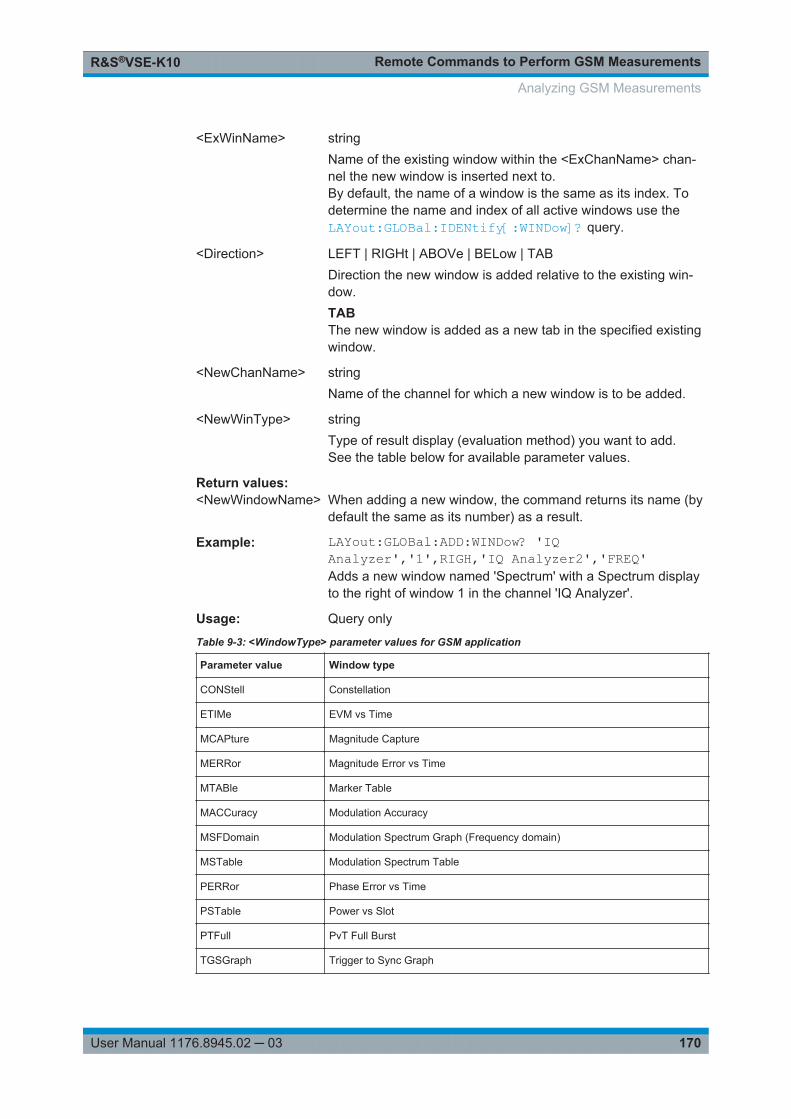
Remote Commands to Perform GSM MeasurementsR&S®VSE-K10
170User Manual 1176.8945.02 ─ 03
<ExWinName> stringName of the existing window within the <ExChanName> chan-nel the new window is inserted next to.By default, the name of a window is the same as its index. Todetermine the name and index of all active windows use theLAYout:GLOBal:IDENtify[:WINDow]? query.
<Direction> LEFT | RIGHt | ABOVe | BELow | TABDirection the new window is added relative to the existing win-dow.TABThe new window is added as a new tab in the specified existingwindow.
<NewChanName> stringName of the channel for which a new window is to be added.
<NewWinType> stringType of result display (evaluation method) you want to add.See the table below for available parameter values.
Return values: <NewWindowName> When adding a new window, the command returns its name (by
default the same as its number) as a result.
Example: LAYout:GLOBal:ADD:WINDow? 'IQAnalyzer','1',RIGH,'IQ Analyzer2','FREQ'Adds a new window named 'Spectrum' with a Spectrum displayto the right of window 1 in the channel 'IQ Analyzer'.
Usage: Query only
Table 9-3: <WindowType> parameter values for GSM application
Parameter value Window type
CONStell Constellation
ETIMe EVM vs Time
MCAPture Magnitude Capture
MERRor Magnitude Error vs Time
MTABle Marker Table
MACCuracy Modulation Accuracy
MSFDomain Modulation Spectrum Graph (Frequency domain)
MSTable Modulation Spectrum Table
PERRor Phase Error vs Time
PSTable Power vs Slot
PTFull PvT Full Burst
TGSGraph Trigger to Sync Graph
Analyzing GSM Measurements
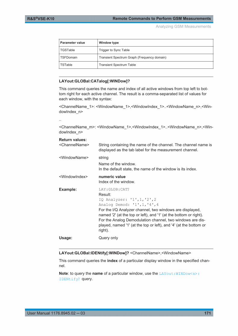
Remote Commands to Perform GSM MeasurementsR&S®VSE-K10
171User Manual 1176.8945.02 ─ 03
Parameter value Window type
TGSTable Trigger to Sync Table
TSFDomain Transient Spectrum Graph (Frequency domain)
TSTable Transient Spectrum Table
LAYout:GLOBal:CATalog[:WINDow]?
This command queries the name and index of all active windows from top left to bot-tom right for each active channel. The result is a comma-separated list of values foreach window, with the syntax:
<ChannelName_1>: <WindowName_1>,<WindowIndex_1>..<WindowName_n>,<Win-dowIndex_n>
..
<ChannelName_m>: <WindowName_1>,<WindowIndex_1>..<WindowName_n>,<Win-dowIndex_n>
Return values: <ChannelName> String containing the name of the channel. The channel name is
displayed as the tab label for the measurement channel.
<WindowName> stringName of the window.In the default state, the name of the window is its index.
<WindowIndex> numeric valueIndex of the window.
Example: LAY:GLOB:CAT?Result:IQ Analyzer: '1',1,'2',2Analog Demod: '1',1,'4',4For the I/Q Analyzer channel, two windows are displayed,named '2' (at the top or left), and '1' (at the bottom or right).For the Analog Demodulation channel, two windows are dis-played, named '1' (at the top or left), and '4' (at the bottom orright).
Usage: Query only
LAYout:GLOBal:IDENtify[:WINDow]? <ChannelName>,<WindowName>
This command queries the index of a particular display window in the specified chan-nel.
Note: to query the name of a particular window, use the LAYout:WINDow<n>:IDENtify? query.
Analyzing GSM Measurements
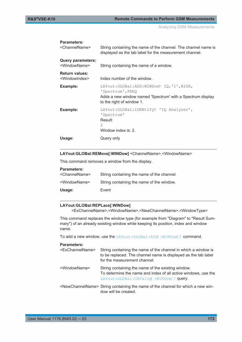
Remote Commands to Perform GSM MeasurementsR&S®VSE-K10
172User Manual 1176.8945.02 ─ 03
Parameters:<ChannelName> String containing the name of the channel. The channel name is
displayed as the tab label for the measurement channel.
Query parameters: <WindowName> String containing the name of a window.
Return values: <WindowIndex> Index number of the window.
Example: LAYout:GLOBal:ADD:WINDow? IQ,'1',RIGH,'Spectrum',FREQAdds a new window named 'Spectrum' with a Spectrum displayto the right of window 1.
Example: LAYout:GLOBal:IDENtify? 'IQ Analyzer','Spectrum'Result:2Window index is: 2.
Usage: Query only
LAYout:GLOBal:REMove[:WINDow] <ChannelName>,<WindowName>
This command removes a window from the display.
Parameters:<ChannelName> String containing the name of the channel.
<WindowName> String containing the name of the window.
Usage: Event
LAYout:GLOBal:REPLace[:WINDow]<ExChannelName>,<WindowName>,<NewChannelName>,<WindowType>
This command replaces the window type (for example from "Diagram" to "Result Sum-mary") of an already existing window while keeping its position, index and windowname.
To add a new window, use the LAYout:GLOBal:ADD[:WINDow]? command.
Parameters:<ExChannelName> String containing the name of the channel in which a window is
to be replaced. The channel name is displayed as the tab labelfor the measurement channel.
<WindowName> String containing the name of the existing window.To determine the name and index of all active windows, use theLAYout:GLOBal:CATalog[:WINDow]? query.
<NewChannelName> String containing the name of the channel for which a new win-dow will be created.
Analyzing GSM Measurements
Remote Commands to Perform GSM MeasurementsR&S®VSE-K10
173User Manual 1176.8945.02 ─ 03
<WindowType> Type of result display you want to use in the existing window.Note that the window type must be valid for the specified chan-nel (<NewChannelName>).See LAYout:ADD[:WINDow]? on page 173 for a list of availa-ble window types.
Example: LAY:GLOB:REPL:WIND 'IQ Analyzer','1','AnalogDemod',MTABReplaces the I/Q Analyzer result display in window 1 by amarker table for the AnalogDemod channel.
9.6.1.2 Working with Windows in the Display
The following commands are required to change the evaluation type and rearrange thescreen layout for a channel as you do in manual operation. Since the available evalua-tion types depend on the selected application, some parameters for the following com-mands also depend on the selected channel.
Note that the suffix <n> always refers to the window in the currently selected channel.
To configure the layout of windows across channels, use the Chapter 9.6.1.1, "GlobalLayout Commands", on page 169.
LAYout:ADD[:WINDow]?.................................................................................................173LAYout:CATalog[:WINDow]?...........................................................................................175LAYout:IDENtify[:WINDow]?............................................................................................175LAYout:REMove[:WINDow].............................................................................................176LAYout:REPLace[:WINDow]............................................................................................176LAYout:WINDow<n>:ADD?.............................................................................................177LAYout:WINDow<n>:IDENtify?........................................................................................177LAYout:WINDow<n>:REMove......................................................................................... 178LAYout:WINDow<n>:REPLace........................................................................................178LAYout:WINDow<n>:TYPe?............................................................................................179
LAYout:ADD[:WINDow]? <WindowName>,<Direction>,<WindowType>
This command adds a window to the display in the active channel.
This command is always used as a query so that you immediately obtain the name ofthe new window as a result.
To replace an existing window, use the LAYout:REPLace[:WINDow] command.
Query parameters: <WindowName> String containing the name of the existing window the new win-
dow is inserted next to.By default, the name of a window is the same as its index. Todetermine the name and index of all active windows, use theLAYout:CATalog[:WINDow]? query.
<Direction> LEFT | RIGHt | ABOVe | BELowDirection the new window is added relative to the existing win-dow.
Analyzing GSM Measurements
Remote Commands to Perform GSM MeasurementsR&S®VSE-K10
174User Manual 1176.8945.02 ─ 03
<WindowType> text valueType of result display (evaluation method) you want to add.See the table below for available parameter values.Note that the window type must be valid for the active channel.To create a window for a different channel use the LAYout:GLOBal:REPLace[:WINDow] command.
Return values: <NewWindowName> When adding a new window, the command returns its name (by
default the same as its number) as a result.
Example: LAY:ADD:WIND? '1',RIGH,MACCAdds a Modulation Accuracy display to the right of window 1.
Usage: Query only
Manual operation: See "Constellation" on page 12See "EVM" on page 13See "Magnitude Capture" on page 13See "Magnitude Error" on page 14See " Marker Table " on page 15See "Modulation Accuracy" on page 15See "Modulation Spectrum Graph" on page 17See "Modulation Spectrum Table" on page 18See "Phase Error" on page 20See "Power vs Slot" on page 21See "PvT Full Burst" on page 22See "Transient Spectrum Graph" on page 24See "Transient Spectrum Table" on page 25See "Trigger to Sync Graph" on page 26See "Trigger to Sync Table" on page 28
For a detailed example see Chapter 9.10.1, "Programming Example: Determining theEVM", on page 248.
Table 9-4: <WindowType> parameter values for GSM application
Parameter value Window type
Default I/Q (Modulation Accuracy,...) measurement:
CONStell Constellation
ETIMe EVM vs. Time
MCAPture Magnitude Capture
MERRor Magnitude Error vs. Time
MTABle Marker Table
MACCuracy Modulation Accuracy
MSFDomain Modulation Spectrum Graph (Frequency domain)
MSTable Modulation Spectrum Table
PERRor Phase Error vs. Time
Analyzing GSM Measurements
Remote Commands to Perform GSM MeasurementsR&S®VSE-K10
175User Manual 1176.8945.02 ─ 03
Parameter value Window type
PSTable Power vs. Slot
PTFull PvT Full Burst
TGSGraph Trigger vs. Sync Graph
TGSTable Trigger to Sync Table
TSFDomain Transient Spectrum Graph (Frequency domain)
TSTable Transient Spectrum Table
LAYout:CATalog[:WINDow]?
This command queries the name and index of all active windows in the active channelfrom top left to bottom right. The result is a comma-separated list of values for eachwindow, with the syntax:
<WindowName_1>,<WindowIndex_1>..<WindowName_n>,<WindowIndex_n>
To query the name and index of all windows in all channels use the LAYout:GLOBal:CATalog[:WINDow]? command.
Return values: <WindowName> string
Name of the window.In the default state, the name of the window is its index.
<WindowIndex> numeric valueIndex of the window.
Example: LAY:CAT?Result:'2',2,'1',1Two windows are displayed, named '2' (at the top or left), and '1'(at the bottom or right).
Usage: Query only
LAYout:IDENtify[:WINDow]? <WindowName>
This command queries the index of a particular display window in the active channel.
Note: to query the name of a particular window, use the LAYout:WINDow<n>:IDENtify? query.
To query the index of a window in a different channel use the LAYout:GLOBal:IDENtify[:WINDow]? command.
Query parameters: <WindowName> String containing the name of a window.
Analyzing GSM Measurements
Remote Commands to Perform GSM MeasurementsR&S®VSE-K10
176User Manual 1176.8945.02 ─ 03
Return values: <WindowIndex> Index number of the window.
Example: LAY:WIND:IDEN? '2'Queries the index of the result display named '2'.Response:2
Usage: Query only
LAYout:REMove[:WINDow] <WindowName>
This command removes a window from the display in the active channel.
To remove a window for a different channel use the LAYout:GLOBal:REMove[:WINDow] command.
Setting parameters: <WindowName> String containing the name of the window.
In the default state, the name of the window is its index.
Example: LAY:REM '2'Removes the result display in the window named '2'.
Usage: Event
LAYout:REPLace[:WINDow] <WindowName>,<WindowType>
This command replaces the window type (for example from "Diagram" to "Result Sum-mary") of an already existing window in the active channel while keeping its position,index and window name.
To add a new window, use the LAYout:ADD[:WINDow]? command.
Parameters:<WindowName> String containing the name of the existing window.
By default, the name of a window is the same as its index. Todetermine the name and index of all active windows in the activechannel, use the LAYout:CATalog[:WINDow]? query.
<WindowType> Type of result display you want to use in the existing window.See LAYout:ADD[:WINDow]? on page 173 for a list of availa-ble window types.Note that the window type must be valid for the active channel.To create a window for a different channel use the LAYout:GLOBal:REPLace[:WINDow] command.
Example: LAY:REPL:WIND '1',MTABReplaces the result display in window 1 with a marker table.
Analyzing GSM Measurements
Remote Commands to Perform GSM MeasurementsR&S®VSE-K10
177User Manual 1176.8945.02 ─ 03
LAYout:WINDow<n>:ADD? <Direction>,<WindowType>
This command adds a measurement window to the display. Note that with this com-mand, the suffix <n> determines the existing window next to which the new window isadded, as opposed to LAYout:ADD[:WINDow]?, for which the existing window isdefined by a parameter.
To replace an existing window, use the LAYout:WINDow<n>:REPLace command.
This command is always used as a query so that you immediately obtain the name ofthe new window as a result.
Suffix: <n>
.Window
Parameters:<Direction> LEFT | RIGHt | ABOVe | BELow
<WindowType> Type of measurement window you want to add.See LAYout:ADD[:WINDow]? on page 173 for a list of availa-ble window types.Note that the window type must be valid for the active channel.To create a window for a different channel use the LAYout:GLOBal:ADD[:WINDow]? command.
Return values: <NewWindowName> When adding a new window, the command returns its name (by
default the same as its number) as a result.
Example: LAY:WIND1:ADD? LEFT,MTABResult:'2'Adds a new window named '2' with a marker table to the left ofwindow 1.
Usage: Query only
LAYout:WINDow<n>:IDENtify?
This command queries the name of a particular display window (indicated by the <n>suffix) in the active channel.
Note: to query the index of a particular window, use the LAYout:IDENtify[:WINDow]? command.
Suffix: <n>
.Window
Return values: <WindowName> String containing the name of a window.
In the default state, the name of the window is its index.
Analyzing GSM Measurements
Remote Commands to Perform GSM MeasurementsR&S®VSE-K10
178User Manual 1176.8945.02 ─ 03
Example: LAY:WIND2:IDEN?Queries the name of the result display in window 2.Response:'2'
Usage: Query only
LAYout:WINDow<n>:REMove
This command removes the window specified by the suffix <n> from the display in theactive channel.
The result of this command is identical to the LAYout:REMove[:WINDow] command.
To remove a window in a different channel use the LAYout:GLOBal:REMove[:WINDow] command.
Suffix: <n>
.Window
Example: LAY:WIND2:REMRemoves the result display in window 2.
Usage: Event
LAYout:WINDow<n>:REPLace <WindowType>
This command changes the window type of an existing window (specified by the suffix<n>) in the active channel.
The result of this command is identical to the LAYout:REPLace[:WINDow] com-mand.
To add a new window, use the LAYout:WINDow<n>:ADD? command.
Suffix: <n>
.Window
Setting parameters: <WindowType> Type of measurement window you want to replace another one
with.See LAYout:ADD[:WINDow]? on page 173 for a list of availa-ble window types.Note that the window type must be valid for the active channel.To create a window for a different channel use the LAYout:GLOBal:REPLace[:WINDow] command.
Example: LAY:WIND2:REPL MTABReplaces the result display in window 2 with a marker table.
Analyzing GSM Measurements
Remote Commands to Perform GSM MeasurementsR&S®VSE-K10
179User Manual 1176.8945.02 ─ 03
LAYout:WINDow<n>:TYPe?
Queries the window type of the window specified by the index <n>. For a list of possi-ble window types see LAYout:ADD[:WINDow]? on page 173.
Suffix: <n>
.Window
Example: LAY:WIND2:TYPE?Response:MACCModulation accuracy
Usage: Query only
9.6.1.3 General Window Commands
The following commands are required to work with windows, independently of theapplication.
Note that the suffix <n> always refers to the window in the currently selected measure-ment channel.
DISPlay:FORMat........................................................................................................... 179DISPlay[:WINDow<n>]:SELect........................................................................................ 179
DISPlay:FORMat <Format>
This command determines which tab is displayed.
Parameters:<Format> SPLit
Displays the MultiView tab with an overview of all active chan-nelsSINGleDisplays the measurement channel that was previously focused.*RST: SING
Example: DISP:FORM SPL
DISPlay[:WINDow<n>]:SELect
This command sets the focus on the selected result display window.
This window is then the active window.
Suffix: <n>
.Window
Example: //Put the focus on window 1DISP:WIND1:SEL
Usage: Setting only
Analyzing GSM Measurements
Remote Commands to Perform GSM MeasurementsR&S®VSE-K10
180User Manual 1176.8945.02 ─ 03
9.6.2 Result Config
Some evaluation methods require or allow for additional settings to configure the resultdisplay. Note that the available settings depend on the selected window.
● Traces................................................................................................................... 180● Exporting Trace Results to an ASCII File..............................................................182● Marker...................................................................................................................184● Scaling.................................................................................................................. 189
9.6.2.1 Traces
The number of available traces depends on the selected window (see " Specifics for "on page 56). Only graphical evaluations have trace settings.
DISPlay[:WINDow<n>]:TRACe<t>[:STATe].......................................................................180DISPlay[:WINDow<n>]:TRACe<t>:MODE.........................................................................180
DISPlay[:WINDow<n>]:TRACe<t>[:STATe] <State>
This command turns a trace on and off.
The measurement continues in the background.
Suffix: <n>
.Window
<t> Trace
Parameters:<State> ON | OFF | 1 | 0
*RST: 1 for TRACe1, 0 for TRACe 2 to 6
Example: DISP:TRAC3 ONManual operation: See "Trace 1/Trace 2/Trace 3/Trace 4" on page 94
DISPlay[:WINDow<n>]:TRACe<t>:MODE <Mode>
This command controls whether a trace is displayed or not, and in which mode. Eachtrace can only display a certain mode, or nothing at all ("Blank"). Table 9-5 below indi-cates which measurements can display which traces and which trace modes.
Note: even if a trace is not displayed, the results can still be queried (see TRACe<n>[:DATA]? on page 196).
In case of max hold, min hold or average trace mode, you can set the number of singlemeasurements with [SENSe:]SWEep:COUNt. Note that synchronization to the end ofthe measurement is possible only in single capture mode.
For a description of the trace modes see the "Trace Mode Overview" section in thebase unit manual.
Suffix: <n>
.Window
Analyzing GSM Measurements
Remote Commands to Perform GSM MeasurementsR&S®VSE-K10
181User Manual 1176.8945.02 ─ 03
<t> Trace
Parameters:<Mode> AVERage
The average is formed over several captures. The "Capture/Average Count" determines the number of averaging proce-dures.BLANkHides the selected trace.MAXHoldThe maximum value is determined over several measurementsand displayed. The R&S VSE saves the measurement result inthe trace memory only if the new value is greater than the previ-ous one.MINHoldThe minimum value is determined from several measurementsand displayed. The R&S VSE saves the measurement result inthe trace memory only if the new value is lower than the previ-ous one.PDFavgThe probability density function (PDF) of the average value.WRITeOverwrite mode: the trace is overwritten by each capture.
Example: // Preset the instrument*RST// Enter the GSM option K10INSTrument:SELect GSM// Switch to single capture mode and stop measurementINITiate:CONTinuous OFF;:ABORt// Modulation spectrum graph measurementLAY:ADD:WIND? '1',RIGH,MSFD//Result: 2INITiate:IMMediate// Switch off the display of all available tracesDISPlay:WINDow2:TRACe1:MODE BLANkDISPlay:WINDow2:TRACe2:MODE BLANk// Switch on the display of all available traces againDISPlay:WINDow2:TRACe1:MODE AVERageDISPlay:WINDow2:TRACe2:MODE WRITe
Manual operation: See "Trigger to Sync Graph" on page 26See "Trace Mode" on page 94
Analyzing GSM Measurements
Remote Commands to Perform GSM MeasurementsR&S®VSE-K10
182User Manual 1176.8945.02 ─ 03
Table 9-5: Available traces and trace modes for the result diplays
Measurement Trace 1 Trace 2 Trace 3 Trace 4
Magnitude Capture
Constellation Graph
WRITe - - -
EVM
Phase Error
Magnitude Error
PvT Full Burst
AVERage MAXHold MINHold WRITe
Modulation Spectrum Graph
Transient Spectrum Graph
AVERage WRITe - -
Trigger to Sync WRITe
(histogram)
PDFavg - -
9.6.2.2 Exporting Trace Results to an ASCII File
Trace results can be exported to an ASCII file for further evaluation in other (external)applications.
FORMat[:DATA].............................................................................................................182FORMat:DEXPort:DSEParator........................................................................................ 183FORMat:DEXPort:HEADer..............................................................................................183FORMat:DEXPort:TRACes............................................................................................. 184MMEMory:STORe<n>:TRACe.........................................................................................184
FORMat[:DATA] <Format>
This command selects the data format that is used for transmission of trace data fromthe R&S VSE to the controlling computer.
Note that the command has no effect for data that you send to the R&S VSE. TheR&S VSE automatically recognizes the data it receives, regardless of the format.
Analyzing GSM Measurements
Remote Commands to Perform GSM MeasurementsR&S®VSE-K10
183User Manual 1176.8945.02 ─ 03
Parameters:<Format> ASCii
ASCii format, separated by commas.This format is almost always suitable, regardless of the actualdata format. However, the data is not as compact as other for-mats may be.REAL,1616-bit floating-point numbers (according to IEEE 754) in the"definite length block format".Compared to REAL,32 format, half as many numbers arereturned.REAL,3232-bit floating-point numbers (according to IEEE 754) in the"definite length block format".For I/Q data, 8 bytes per sample are returned for this format set-ting.REAL,6464-bit floating-point numbers (according to IEEE 754) in the"definite length block format".Compared to REAL,32 format, twice as many numbers arereturned.*RST: ASCII
Example: FORM REAL,32
FORMat:DEXPort:DSEParator <Separator>
This command selects the decimal separator for data exported in ASCII format.
Parameters:<Separator> COMMa
Uses a comma as decimal separator, e.g. 4,05.POINtUses a point as decimal separator, e.g. 4.05.*RST: *RST has no effect on the decimal separator.
Default is POINt.
Example: FORM:DEXP:DSEP POINSets the decimal point as separator.
Manual operation: See " Decimal Separator " on page 96
FORMat:DEXPort:HEADer <State>
If enabled, additional instrument and measurement settings are included in the headerof the export file for result data. If disabled, only the pure result data from the selectedtraces and tables is exported.
Analyzing GSM Measurements
Remote Commands to Perform GSM MeasurementsR&S®VSE-K10
184User Manual 1176.8945.02 ─ 03
Parameters:<State> ON | OFF | 0 | 1
*RST: 1
Manual operation: See " Include Instrument & Measurement Settings " on page 95
FORMat:DEXPort:TRACes <Selection>
This command selects the data to be included in a data export file (see MMEMory:STORe<n>:TRACe on page 184).
Parameters:<Selection> SINGle
Only a single trace is selected for export, namely the one speci-fied by the MMEMory:STORe<n>:TRACe command.
ALLSelects all active traces and result tables (e.g. Result Summary,marker peak list etc.) in the current application for export to anASCII file.The <trace> parameter for the MMEMory:STORe<n>:TRACecommand is ignored.*RST: SINGle
Manual operation: See " Export all Traces and all Table Results " on page 95
MMEMory:STORe<n>:TRACe <Trace>, <FileName>
This command exports trace data from the specified window to an ASCII file.
Suffix: <n>
.Window
Setting parameters: <Trace> Number of the trace to be stored
<FileName> String containing the path and name of the target file.
Example: MMEM:STOR1:TRAC 1,'C:\TEST.ASC'Stores trace 1 from window 1 in the file TEST.ASC.
Usage: Setting only
9.6.2.3 Marker
Markers help you analyze your measurement results by determining particular valuesin the diagram. Thus you can extract numeric values from a graphical display. Up to 4markers can be configured.
● Individual Marker Settings.....................................................................................185● General Marker Settings....................................................................................... 187● Marker Positioning Settings.................................................................................. 187
Analyzing GSM Measurements
Remote Commands to Perform GSM MeasurementsR&S®VSE-K10
185User Manual 1176.8945.02 ─ 03
Individual Marker Settings
In GSM evaluations, up to 4 markers can be activated in each diagram at any time. thefollowing commands are required to configure the markers.
CALCulate<n>:DELTamarker<m>:AOFF..........................................................................185CALCulate<n>:DELTamarker<m>[:STATe].......................................................................185CALCulate<n>:DELTamarker<m>:TRACe........................................................................185CALCulate<n>:MARKer<m>[:STATe]...............................................................................186CALCulate<n>:MARKer<m>:AOFF..................................................................................186CALCulate<n>:MARKer<m>:TRACe................................................................................186
CALCulate<n>:DELTamarker<m>:AOFF
This command turns off all delta markers.
Suffix: <n>
.Window
<m> irrelevant
Example: CALC:DELT:AOFFTurns off all delta markers.
Usage: Event
CALCulate<n>:DELTamarker<m>[:STATe] <State>
This command turns delta markers on and off.
If necessary, the command activates the delta marker first.
No suffix at DELTamarker turns on delta marker 1.
Suffix: <n>
.Window
<m> Marker
Parameters:<State> ON | OFF | 1 | 0
*RST: 0
Example: CALC:DELT2 ONTurns on delta marker 2.
Manual operation: See " Marker 1/ Delta 1/ Delta 2/.../Delta 4" on page 97See " Marker State " on page 98See " Marker Type " on page 98
CALCulate<n>:DELTamarker<m>:TRACe <Trace>
This command selects the trace a delta marker is positioned on.
Note that the corresponding trace must have a trace mode other than "Blank".
Analyzing GSM Measurements
Remote Commands to Perform GSM MeasurementsR&S®VSE-K10
186User Manual 1176.8945.02 ─ 03
If necessary, the command activates the marker first.
Suffix: <n>
.Window
<m> Marker
Parameters:<Trace> Trace number the marker is assigned to.
Example: CALC:DELT2:TRAC 2Positions delta marker 2 on trace 2.
CALCulate<n>:MARKer<m>[:STATe] <State>
This command turns markers on and off. If the corresponding marker number is cur-rently active as a delta marker, it is turned into a normal marker.
Suffix: <n>
.Window
<m> Marker
Parameters:<State> ON | OFF | 1 | 0
*RST: 0
Example: CALC:MARK3 ONSwitches on marker 3.
Manual operation: See " Marker 1/ Delta 1/ Delta 2/.../Delta 4" on page 97See " Marker State " on page 98See " Marker Type " on page 98
CALCulate<n>:MARKer<m>:AOFF
This command turns off all markers.
Suffix: <n>
.Window
<m> Marker
Example: CALC:MARK:AOFFSwitches off all markers.
Usage: Event
Manual operation: See " All Marker Off " on page 98
CALCulate<n>:MARKer<m>:TRACe <Trace>
This command selects the trace the marker is positioned on.
Note that the corresponding trace must have a trace mode other than "Blank".
Analyzing GSM Measurements
Remote Commands to Perform GSM MeasurementsR&S®VSE-K10
187User Manual 1176.8945.02 ─ 03
If necessary, the command activates the marker first.
Suffix: <n>
.Window
<m> Marker
Parameters:<Trace> 1 to 4
Trace number the marker is assigned to.
Example: CALC:MARK3:TRAC 2Assigns marker 3 to trace 2.
Manual operation: See " Assigning the Marker to a Trace " on page 98
General Marker Settings
The following commands define general settings for all markers.
DISPlay:MTABle............................................................................................................ 187
DISPlay:MTABle <DisplayMode>
This command turns the marker table on and off.
Parameters:<DisplayMode> ON | 1
Turns on the marker table.OFF | 0Turns off the marker table.*RST: AUTO
Example: DISP:MTAB ONActivates the marker table.
Manual operation: See " Marker Table Display " on page 99
Marker Positioning Settings
The following commands are required to set a specific marker to the result of a peaksearch.
CALCulate<n>:MARKer<m>:MAXimum:APEak.................................................................187CALCulate<n>:MARKer<m>:MAXimum[:PEAK]................................................................ 188CALCulate<n>:MARKer<m>:MINimum[:PEAK]................................................................. 188CALCulate<n>:DELTamarker<m>:MAXimum:APEak.........................................................188CALCulate<n>:DELTamarker<m>:MAXimum[:PEAK]........................................................ 188CALCulate<n>:DELTamarker<m>:MINimum[:PEAK]......................................................... 189
CALCulate<n>:MARKer<m>:MAXimum:APEak
sets the marker to the largest absolute peak value (maximum or minimum) of theselected trace.
Analyzing GSM Measurements
Remote Commands to Perform GSM MeasurementsR&S®VSE-K10
188User Manual 1176.8945.02 ─ 03
Suffix: <n>
.Window
<m> Marker
Usage: Event
Manual operation: See "Max |Peak|" on page 100
CALCulate<n>:MARKer<m>:MAXimum[:PEAK]
This command moves a marker to the highest level.
If the marker is not yet active, the command first activates the marker.
Suffix: <n>
.Window
<m> Marker
Usage: Event
Manual operation: See " Peak Search " on page 100
CALCulate<n>:MARKer<m>:MINimum[:PEAK]
This command moves a marker to the minimum level.
If the marker is not yet active, the command first activates the marker.
Suffix: <n>
.Window
<m> Marker
Usage: Event
Manual operation: See " Search Minimum " on page 100
CALCulate<n>:DELTamarker<m>:MAXimum:APEak
This command positions the active marker or delta marker on the largest absolutepeak value (maximum or minimum) of the selected trace.
Suffix: <n>
.Window
<m> Marker
Usage: Event
CALCulate<n>:DELTamarker<m>:MAXimum[:PEAK]
This command moves a delta marker to the highest level.
If the marker is not yet active, the command first activates the marker.
Analyzing GSM Measurements
Remote Commands to Perform GSM MeasurementsR&S®VSE-K10
189User Manual 1176.8945.02 ─ 03
Suffix: <n>
.Window
<m> Marker
Usage: Event
Manual operation: See " Peak Search " on page 100
CALCulate<n>:DELTamarker<m>:MINimum[:PEAK]
This command moves a delta marker to the minimum level.
If the marker is not yet active, the command first activates the marker.
Suffix: <n>
.Window
<m> Marker
Usage: Event
Manual operation: See " Search Minimum " on page 100
9.6.2.4 Scaling
The scaling for the vertical axis is highly configurable, using either absolute or relativevalues. These commands are described here.
DISPlay[:WINDow<n>]:TRACe<t>:Y[:SCALe]:AUTO......................................................... 189DISPlay[:WINDow<n>]:TRACe<t>:Y[:SCALe]:MAXimum................................................... 190DISPlay[:WINDow<n>]:TRACe<t>:Y[:SCALe]:MINimum.....................................................190DISPlay[:WINDow<n>]:TRACe<t>:Y[:SCALe]:PDIVision.................................................... 190DISPlay[:WINDow<n>]:TRACe<t>:Y[:SCALe]:RPOSition................................................... 191DISPlay[:WINDow<n>]:TRACe<t>:Y[:SCALe]:RVALue...................................................... 191DISPlay[:WINDow<n>]:TRACe<t>:Y[:SCALe]:RVALue:MAXimum...................................... 192DISPlay[:WINDow<n>]:TRACe<t>:Y[:SCALe]:RVALue:MINimum........................................192
DISPlay[:WINDow<n>]:TRACe<t>:Y[:SCALe]:AUTO <State>
If enabled, the Y-axis is scaled automatically according to the current measurement.
Suffix: <n>
.Window
<t> irrelevant
Parameters for setting and query: <State> OFF
Switch the function offONSwitch the function on*RST: ON
Manual operation: See "Automatic Grid Scaling" on page 101
Analyzing GSM Measurements
Remote Commands to Perform GSM MeasurementsR&S®VSE-K10
190User Manual 1176.8945.02 ─ 03
DISPlay[:WINDow<n>]:TRACe<t>:Y[:SCALe]:MAXimum <Value>
This command defines the maximum value of the y-axis for all traces in the selectedresult display.
Suffix: <n>
.Window
<t> irrelevant
Parameters:<Value> <numeric value>
*RST: depends on the result displayThe unit and range depend on the result display.
Example: DISP:TRAC:Y:MIN -60DISP:TRAC:Y:MAX 0Defines the y-axis with a minimum value of -60 and maximumvalue of 0.
Manual operation: See "Absolute Scaling (Min/Max Values)" on page 101
DISPlay[:WINDow<n>]:TRACe<t>:Y[:SCALe]:MINimum <Value>
This command defines the minimum value of the y-axis for all traces in the selectedresult display.
Suffix: <n>
.Window
<t> irrelevant
Parameters:<Value> <numeric value>
*RST: depends on the result displayThe unit and range depend on the result display.
Example: DISP:TRAC:Y:MIN -60DISP:TRAC:Y:MAX 0Defines the y-axis with a minimum value of -60 and maximumvalue of 0.
Manual operation: See "Absolute Scaling (Min/Max Values)" on page 101
DISPlay[:WINDow<n>]:TRACe<t>:Y[:SCALe]:PDIVision <Value>
This remote command determines the grid spacing on the Y-axis for all diagrams,where possible.
Suffix: <n>
.Window
<t> irrelevant
Analyzing GSM Measurements
Remote Commands to Perform GSM MeasurementsR&S®VSE-K10
191User Manual 1176.8945.02 ─ 03
Parameters:<Value> numeric value WITHOUT UNIT (unit according to the result dis-
play)Defines the range per division (total range = 10*<Value>)*RST: depends on the result display
Example: DISP:TRAC:Y:PDIV 10Sets the grid spacing to 10 units (e.g. dB) per division
Manual operation: See "Per Division" on page 101
DISPlay[:WINDow<n>]:TRACe<t>:Y[:SCALe]:RPOSition <Position>
This command defines the vertical position of the reference level on the display grid(for all traces).
The R&S VSE adjusts the scaling of the y-axis accordingly.
Suffix: <n>
.Window
<t> irrelevant
Parameters:<Position> 0 PCT corresponds to the lower display border, 100% corre-
sponds to the upper display border.*RST: 100 PCT = frequency display; 50 PCT = time dis-
play
Example: DISP:TRAC:Y:RPOS 50PCTManual operation: See "Ref Position" on page 102
DISPlay[:WINDow<n>]:TRACe<t>:Y[:SCALe]:RVALue <Value>
The command defines the power value assigned to the reference position in the grid(for all traces).
Suffix: <n>
.Window
<t> irrelevant
Parameters:<Value> *RST: 0 dBm, coupled to reference level
Example: DISP:TRAC:Y:RVAL -20dBmSets the power value assigned to the reference position to -20dBm
Manual operation: See "Ref Value" on page 102
Analyzing GSM Measurements
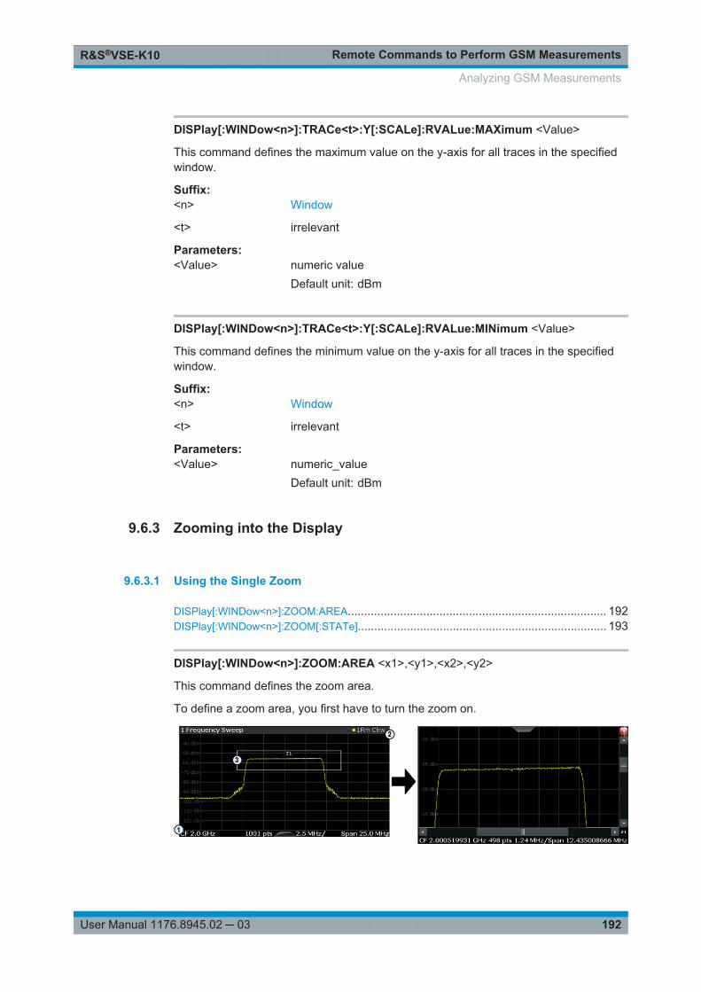
Remote Commands to Perform GSM MeasurementsR&S®VSE-K10
192User Manual 1176.8945.02 ─ 03
DISPlay[:WINDow<n>]:TRACe<t>:Y[:SCALe]:RVALue:MAXimum <Value>
This command defines the maximum value on the y-axis for all traces in the specifiedwindow.
Suffix: <n>
.Window
<t> irrelevant
Parameters:<Value> numeric value
Default unit: dBm
DISPlay[:WINDow<n>]:TRACe<t>:Y[:SCALe]:RVALue:MINimum <Value>
This command defines the minimum value on the y-axis for all traces in the specifiedwindow.
Suffix: <n>
.Window
<t> irrelevant
Parameters:<Value> numeric_value
Default unit: dBm
9.6.3 Zooming into the Display
9.6.3.1 Using the Single Zoom
DISPlay[:WINDow<n>]:ZOOM:AREA............................................................................... 192DISPlay[:WINDow<n>]:ZOOM[:STATe]............................................................................ 193
DISPlay[:WINDow<n>]:ZOOM:AREA <x1>,<y1>,<x2>,<y2>
This command defines the zoom area.
To define a zoom area, you first have to turn the zoom on.
Analyzing GSM Measurements
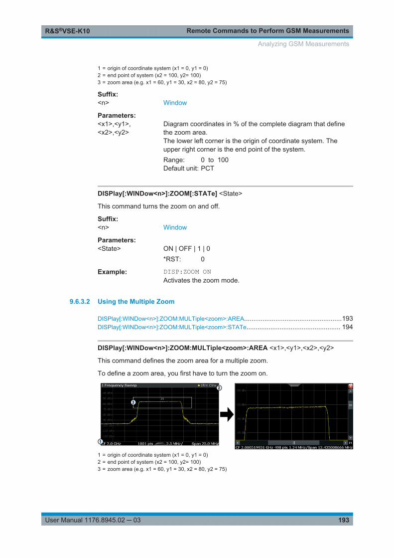
Remote Commands to Perform GSM MeasurementsR&S®VSE-K10
193User Manual 1176.8945.02 ─ 03
1 = origin of coordinate system (x1 = 0, y1 = 0)2 = end point of system (x2 = 100, y2= 100)3 = zoom area (e.g. x1 = 60, y1 = 30, x2 = 80, y2 = 75)
Suffix: <n>
.Window
Parameters:<x1>,<y1>,<x2>,<y2>
Diagram coordinates in % of the complete diagram that definethe zoom area.The lower left corner is the origin of coordinate system. Theupper right corner is the end point of the system.Range: 0 to 100Default unit: PCT
DISPlay[:WINDow<n>]:ZOOM[:STATe] <State>
This command turns the zoom on and off.
Suffix: <n>
.Window
Parameters:<State> ON | OFF | 1 | 0
*RST: 0
Example: DISP:ZOOM ONActivates the zoom mode.
9.6.3.2 Using the Multiple Zoom
DISPlay[:WINDow<n>]:ZOOM:MULTiple<zoom>:AREA.....................................................193DISPlay[:WINDow<n>]:ZOOM:MULTiple<zoom>:STATe................................................... 194
DISPlay[:WINDow<n>]:ZOOM:MULTiple<zoom>:AREA <x1>,<y1>,<x2>,<y2>
This command defines the zoom area for a multiple zoom.
To define a zoom area, you first have to turn the zoom on.
1 = origin of coordinate system (x1 = 0, y1 = 0)2 = end point of system (x2 = 100, y2= 100)3 = zoom area (e.g. x1 = 60, y1 = 30, x2 = 80, y2 = 75)
Analyzing GSM Measurements
Remote Commands to Perform GSM MeasurementsR&S®VSE-K10
194User Manual 1176.8945.02 ─ 03
Suffix: <n>
.Window
<zoom> 1...4Selects the zoom window.
Parameters:<x1>,<y1>,<x2>,<y2>
Diagram coordinates in % of the complete diagram that definethe zoom area.The lower left corner is the origin of coordinate system. Theupper right corner is the end point of the system.Range: 0 to 100Default unit: PCT
DISPlay[:WINDow<n>]:ZOOM:MULTiple<zoom>:STATe <State>
This command turns the multiple zoom on and off.
Suffix: <n>
.Window
<zoom> 1...4Selects the zoom window.If you turn off one of the zoom windows, all subsequent zoomwindows move up one position.
Parameters:<State> ON | OFF | 1 | 0
*RST: 0
9.7 Retrieving Results
The following commands are required to retrieve the results from the GSM measure-ments.
● Graphical Results..................................................................................................195● Measurement Results for TRACe<n>[:DATA]? TRACE<n>.................................201● Magnitude Capture Results...................................................................................204● Modulation Accuracy Results................................................................................205● Modulation Spectrum Results............................................................................... 216● Power vs Slot Results........................................................................................... 218● Transient Spectrum Results..................................................................................226● Trigger to Sync Results.........................................................................................228● Limit Check Results.............................................................................................. 229● Retrieving Marker Results.....................................................................................232
Retrieving Results
Remote Commands to Perform GSM MeasurementsR&S®VSE-K10
195User Manual 1176.8945.02 ─ 03
9.7.1 Graphical Results
The results of the trace queries depend on the selected evaluation (see Chapter 9.7.2,"Measurement Results for TRACe<n>[:DATA]? TRACE<n>", on page 201).
FORMat[:DATA].............................................................................................................195FORMat:DEXPort:DSEParator........................................................................................ 195[SENSe:]IQ:FFT:LENGth?.............................................................................................. 196TRACe<n>[:DATA]?.......................................................................................................196TRACe<n>[:DATA]:X?....................................................................................................197TRACe:IQ:DATA?..........................................................................................................198TRACe:IQ:DATA:FORMat...............................................................................................199TRACe:IQ:DATA:MEMory?............................................................................................. 199
FORMat[:DATA] <Format>
This command selects the data format that is used for transmission of trace data fromthe R&S VSE to the controlling computer.
Note that the command has no effect for data that you send to the R&S VSE. TheR&S VSE automatically recognizes the data it receives, regardless of the format.
Parameters:<Format> ASCii
ASCii format, separated by commas.This format is almost always suitable, regardless of the actualdata format. However, the data is not as compact as other for-mats may be.REAL,1616-bit floating-point numbers (according to IEEE 754) in the"definite length block format".Compared to REAL,32 format, half as many numbers arereturned.REAL,3232-bit floating-point numbers (according to IEEE 754) in the"definite length block format".For I/Q data, 8 bytes per sample are returned for this format set-ting.REAL,6464-bit floating-point numbers (according to IEEE 754) in the"definite length block format".Compared to REAL,32 format, twice as many numbers arereturned.*RST: ASCII
Example: FORM REAL,32
FORMat:DEXPort:DSEParator <Separator>
This command selects the decimal separator for data exported in ASCII format.
Retrieving Results
Remote Commands to Perform GSM MeasurementsR&S®VSE-K10
196User Manual 1176.8945.02 ─ 03
Parameters:<Separator> COMMa
Uses a comma as decimal separator, e.g. 4,05.POINtUses a point as decimal separator, e.g. 4.05.*RST: *RST has no effect on the decimal separator.
Default is POINt.
Example: FORM:DEXP:DSEP POINSets the decimal point as separator.
Manual operation: See " Decimal Separator " on page 96
[SENSe:]IQ:FFT:LENGth?
Queries the number of frequency points determined by each FFT calculation. Themore points are used, the higher the resolution in the spectrum becomes, but the lon-ger the calculation takes.
Return values: <NoOfBins> integer value
Range: 3 to 524288*RST: 1024
Example: IQ:FFT:LENG?// 2048
Usage: Query only
TRACe<n>[:DATA]? <TraceNumber>
This command reads trace data out of the window specified by the suffix <n>. Thiscommand is only available for graphical result displays.
The returned values are scaled in the current level unit. The data format depends onFORMat[:DATA] on page 182.
For Constellation diagrams, the result is a vector of I/Q values for the measured pointsin the diagram. The result is returned as a list of (I,Q) value pairs.
Suffix: <n>
.Window
Retrieving Results
Remote Commands to Perform GSM MeasurementsR&S®VSE-K10
197User Manual 1176.8945.02 ─ 03
Query parameters: <TraceNumber> TRACe1 | TRACe2 | TRACe3 | TRACe4
Trace name to be read outTRACe1Average trace; (transient spectrum: Maximum trace)TRACe2Maximum traceTRACe3Minimum traceTRACe4Current trace
Example: TRAC1:DATA? TRACe1Usage: Query only
Manual operation: See "EVM" on page 13See "Magnitude Capture" on page 13See "Magnitude Error" on page 14See "Modulation Spectrum Graph" on page 17See "Phase Error" on page 20See "PvT Full Burst" on page 22See "Transient Spectrum Graph" on page 24See "Trigger to Sync Graph" on page 26
For a detailed example see Chapter 9.10.1, "Programming Example: Determining theEVM", on page 248.
TRACe<n>[:DATA]:X? <TraceNumber>
This command reads the x-values (time in seconds) of the "Power vs Time" measure-ment (if active) out of the window specified by the suffix <n>.
If a trace number is defined as a parameter for this command, the x-values (time inseconds) of the "Trigger to Sync" measurement (if active) out of the window specifiedby the suffix <n> are returned.
For details see Chapter 9.7.2.5, "Trigger to Sync Results", on page 203.
Suffix: <n>
.Window
Retrieving Results
Remote Commands to Perform GSM MeasurementsR&S®VSE-K10
198User Manual 1176.8945.02 ─ 03
Query parameters: <TraceNumber> TRACe1 | TRACe2 | TRACe3 | TRACe4
Trace numberTRACe1Average trace; (Transient Spectrum: Maximum trace, Trigger toSync: histogram values)TRACe2Maximum trace (Trigger to Sync: PDF of average trace)TRACe3Minimum traceTRACe4Current trace
Example: TRACe2:DATA:X?Returns the Power vs Time values for the active trace in window2.TRACe3:DATA:X? TRACe1Returns the Trigger to Sync values for trace 1 in window 3.
Usage: Query only
Manual operation: See "PvT Full Burst" on page 22See "Trigger to Sync Graph" on page 26
TRACe:IQ:DATA?
This command initiates a measurement with the current settings and returns the cap-tured data from I/Q measurements.
This command corresponds to:
INIT:IMM;*WAI;: TRACe:IQ:DATA:MEMory?However, the TRACe:IQ:DATA? command is quicker in comparison.
Return values: <Results> Measured voltage for I and Q component for each sample that
has been captured during the measurement.Default unit: V
Retrieving Results
Remote Commands to Perform GSM MeasurementsR&S®VSE-K10
199User Manual 1176.8945.02 ─ 03
Example: TRAC:IQ:STAT ONEnables acquisition of I/Q dataTRAC:IQ:SET NORM,10MHz,32MHz,EXT,POS,0,4096Measurement configuration:Sample Rate = 32 MHzTrigger Source = ExternalTrigger Slope = PositivePretrigger Samples = 0Number of Samples = 4096FORMat REAL,32Selects format of response dataTRAC:IQ:DATA?Starts measurement and reads results
Usage: Query only
TRACe:IQ:DATA:FORMat <Format>
This command selects the order of the I/Q data.
Parameters:<Format> COMPatible | IQBLock | IQPair
COMPatibleI and Q values are separated and collected in blocks: A block(512k) of I values is followed by a block (512k) of Q values, fol-lowed by a block of I values, followed by a block of Q values etc.(I,I,I,I,Q,Q,Q,Q,I,I,I,I,Q,Q,Q,Q...)IQBLockFirst all I-values are listed, then the Q-values(I,I,I,I,I,I,...Q,Q,Q,Q,Q,Q)IQPairOne pair of I/Q values after the other is listed(I,Q,I,Q,I,Q...).*RST: IQBL
TRACe:IQ:DATA:MEMory? [<OffsetSamples>,<NoOfSamples>]
This command queries the I/Q data currently stored in the capture buffer of theR&S VSE.
By default, the command returns all I/Q data in the memory. You can, however, narrowdown the amount of data that the command returns using the optional parameters.
If no parameters are specified with the command, the entire trace data is retrieved; inthis case, the command returns the same results as TRACe:IQ:DATA?. (Note, how-ever, that the TRAC:IQ:DATA? command initiates a new measurement before return-ing the captured values, rather than returning the existing data in the memory.)
Retrieving Results
Remote Commands to Perform GSM MeasurementsR&S®VSE-K10
200User Manual 1176.8945.02 ─ 03
The command returns a comma-separated list of the measured values in floating pointformat (comma-separated values = CSV). The number of values returned is 2 * thenumber of complex samples.
The total number of complex samples is displayed in the channel bar in manual opera-tion and can be calculated as:
<SampleRate> * <CaptureTime>
By default, the amount of available data depends on TRACe:IQ:SRATe? on page 156and [SENSe:]SWEep:TIME on page 156.
Parameters:<OffsetSamples> Selects an offset at which the output of data should start in rela-
tion to the first data. If omitted, all captured samples are output,starting with the first sample.Range: 0 to <# of samples> – 1, with <# of samples> being
the maximum number of captured values*RST: 0
<NoOfSamples> Number of samples you want to query, beginning at the offsetyou have defined. If omitted, all captured samples (starting atoffset) are output.Range: 1 to <# of samples> - <offset samples> with <# of
samples> maximum number of captured values*RST: <# of samples>
Return values: <IQData> Measured value pair (I,Q) for each sample that has been recor-
ded.By default, the first half of the list contains the I values, the sec-ond half the Q values. The order can be configured usingTRACe:IQ:DATA:FORMat.The data format of the individual values depends on FORMat[:DATA].
Default unit: V
Retrieving Results
Remote Commands to Perform GSM MeasurementsR&S®VSE-K10
201User Manual 1176.8945.02 ─ 03
Example: // Preset the instrument*RST// Enter GSM optionINST:SEL GSM// Set center frequency to 935 MHzFREQ:CENT 935MHZSample Rate = 6.5 MHzTRAC:IQ:SRAT 6.5MHzCapture Time = 100 msSET:SWE:TIME 0.1 s// Set statistic count to 1 to obtain the I/Q data of a single cap-ture.// Otherwise several captures are performed until the set// statistic count is reached.// I/Q data is returned from the last capture.SWE:COUN 1// Switch to single capture modeINIT:CONT OFF// Start measurement and wait for sync// This performs one sweep or a single I/Q capture.INIT;*WAI// Determine output format (binary float32)FORMat REAL,32// Read I/Q data of the entire capture buffer.// 653751 samples are returned as I,Q,I,Q,...// 653751 * 4 Bytes (float32) * 2 (I+Q) = 5230008 bytesTRAC:IQ:DATA:MEM?// Read 2048 I/Q samples starting at the beginning of data acqui-sitionTRAC:IQ:DATA:MEM? 0,2048// Read 1024 I/Q samples starting at sample 2048.TRAC:IQ:DATA:MEM? 2048,1024
Example: See Chapter 9.10.1, "Programming Example: Determining theEVM", on page 248.
Example: // Perform a single I/Q capture.INIT;*WAI// Determine output format (binary float32)FORMat REAL,32// Read 1024 I/Q samples starting at sample 2048.TRAC:IQ:DATA:MEM? 2048,1024
Usage: Query only
9.7.2 Measurement Results for TRACe<n>[:DATA]? TRACE<n>
The evaluation method selected by the LAY:ADD:WIND command also affects theresults of the trace data query (see TRACe<n>[:DATA]? TRACE<n>).
Retrieving Results
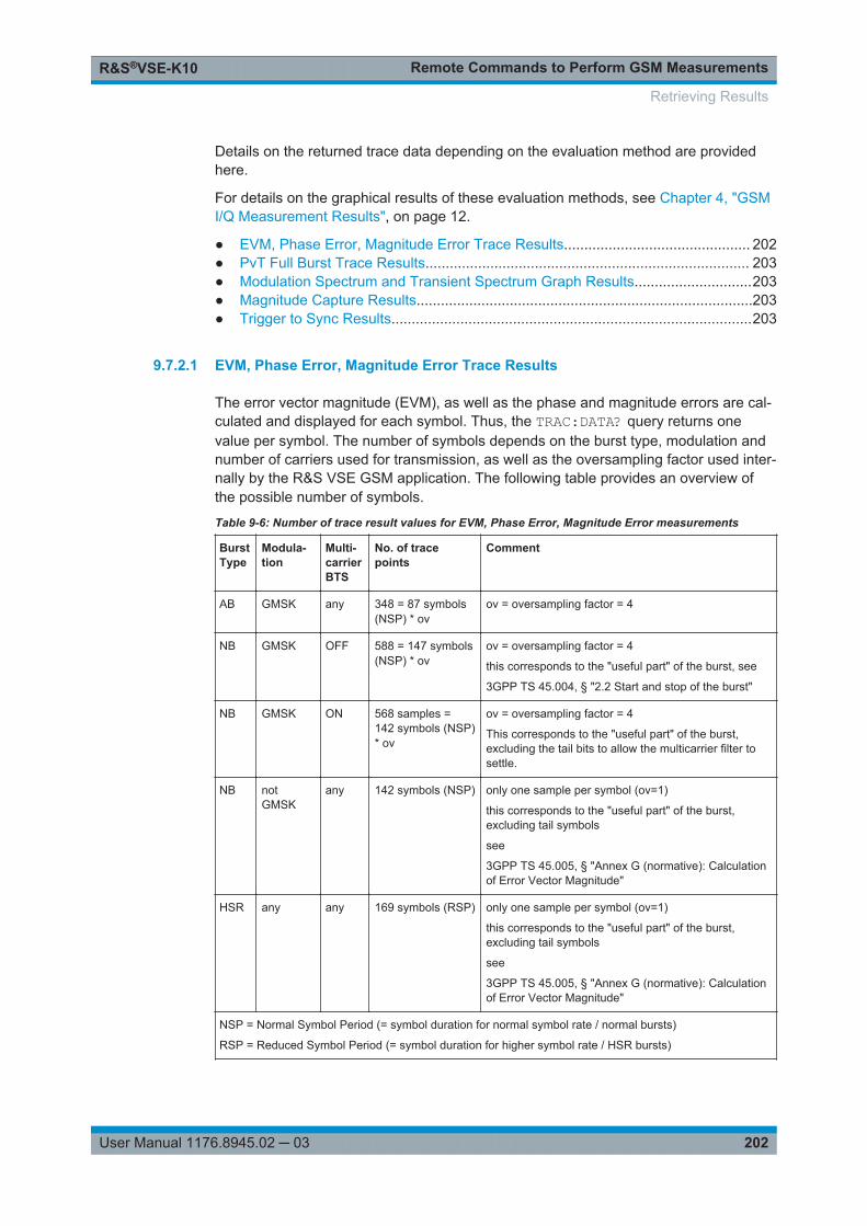
Remote Commands to Perform GSM MeasurementsR&S®VSE-K10
202User Manual 1176.8945.02 ─ 03
Details on the returned trace data depending on the evaluation method are providedhere.
For details on the graphical results of these evaluation methods, see Chapter 4, "GSMI/Q Measurement Results", on page 12.
● EVM, Phase Error, Magnitude Error Trace Results.............................................. 202● PvT Full Burst Trace Results................................................................................ 203● Modulation Spectrum and Transient Spectrum Graph Results.............................203● Magnitude Capture Results...................................................................................203● Trigger to Sync Results.........................................................................................203
9.7.2.1 EVM, Phase Error, Magnitude Error Trace Results
The error vector magnitude (EVM), as well as the phase and magnitude errors are cal-culated and displayed for each symbol. Thus, the TRAC:DATA? query returns onevalue per symbol. The number of symbols depends on the burst type, modulation andnumber of carriers used for transmission, as well as the oversampling factor used inter-nally by the R&S VSE GSM application. The following table provides an overview ofthe possible number of symbols.
Table 9-6: Number of trace result values for EVM, Phase Error, Magnitude Error measurements
BurstType
Modula-tion
Multi-carrierBTS
No. of tracepoints
Comment
AB GMSK any 348 = 87 symbols(NSP) * ov
ov = oversampling factor = 4
NB GMSK OFF 588 = 147 symbols(NSP) * ov
ov = oversampling factor = 4
this corresponds to the "useful part" of the burst, see
3GPP TS 45.004, § "2.2 Start and stop of the burst"
NB GMSK ON 568 samples =142 symbols (NSP)* ov
ov = oversampling factor = 4
This corresponds to the "useful part" of the burst,excluding the tail bits to allow the multicarrier filter tosettle.
NB notGMSK
any 142 symbols (NSP) only one sample per symbol (ov=1)
this corresponds to the "useful part" of the burst,excluding tail symbols
see
3GPP TS 45.005, § "Annex G (normative): Calculationof Error Vector Magnitude"
HSR any any 169 symbols (RSP) only one sample per symbol (ov=1)
this corresponds to the "useful part" of the burst,excluding tail symbols
see
3GPP TS 45.005, § "Annex G (normative): Calculationof Error Vector Magnitude"
NSP = Normal Symbol Period (= symbol duration for normal symbol rate / normal bursts)
RSP = Reduced Symbol Period (= symbol duration for higher symbol rate / HSR bursts)
Retrieving Results
Remote Commands to Perform GSM MeasurementsR&S®VSE-K10
203User Manual 1176.8945.02 ─ 03
9.7.2.2 PvT Full Burst Trace Results
The Power vs Time results depend on the number of slots that are measured, and thusthe duration of the measurement. 30 additional symbols (NSP) are added at the begin-ning and at the end of the trace.
The number of trace result values is calculated as:
(30 + <NofSlots> * 157 + 30) * ov
where:
<NofSlots> = Number of Slots (Slot Scope)
ov = oversampling factor = 24
157 = length of a long slot (a slot can have a length of 156, 156.25 or 157 symbols(NSP))
9.7.2.3 Modulation Spectrum and Transient Spectrum Graph Results
Modulation Spectrum and Transient Spectrum Graphs consist of 1135 trace values(two less than in previous R&S signal and spectrum analyzers).
9.7.2.4 Magnitude Capture Results
The Magnitude Capture trace consists of 32001 trace values, regardless of the definedcapture time and thus of the length of the capture buffer.
9.7.2.5 Trigger to Sync Results
The Trigger to Sync Graph results consist of two traces. Thus, the results of theTRAC:DATA? query depend on the <TraceNumber> parameter.
TRACe1: returns the height of the histogram bins; the number of values is defined bythe number of bins (see CONFigure:TRGS:NOFBins on page 167)
TRACe2: returns the y-values for the probability density function (PDF) of the aver-aged values. The number of values depends on the number of data captures (StatisticCount, see [SENSe:]SWEep:COUNt on page 155).
X-values
The results of the TRAC:DATA:X? query also depend on the <TraceNumber> parame-ter:
TRACe1: returns the time (in s) at the center of each bin in the histogram.
TRACe2: returns the time (in s) for the PDF function of the averaged values
Retrieving Results
Remote Commands to Perform GSM MeasurementsR&S®VSE-K10
204User Manual 1176.8945.02 ─ 03
9.7.3 Magnitude Capture Results
The following commands are required to query the results of the "Magnitude Capture"evaluation.
FETCh:MCAPture:SLOTs:MEASure?...............................................................................204FETCh:MCAPture:SLOTs:SCOPe?................................................................................. 204
FETCh:MCAPture:SLOTs:MEASure?
This command queries the positions of the slots to measure in the current capture buf-fer (indicated by blue bars in the result display).
Return values: <Result> The result is a comma-separated list of positions for each slot
with the following syntax:xPos[0],xLen[0], xPos[1],xLen[1],…where:xPos[i] is the x-value (in seconds) of the i-th slot to measurexLen[i] is the length of the i-th slot to measure (in seconds)The number of values is 2* [the number of GSM frames in thecurrent capture buffer]. If the number of frames defined by thestatistic count all fit into the capture buffer at once, the numberof values is 2*statistic count. If not, the number of values is2*[the number of frames in the last capture].
Example: FETCh:MCAPture:SLOTs:MEASure?Result for 3 slot scopes (e.g. after a single capture mode withstatistic count = 3)0.002261,0.000577,0.006876,0.000577,0.011492,0.000577
Usage: Query only
Manual operation: See "Magnitude Capture" on page 13
FETCh:MCAPture:SLOTs:SCOPe?
This command queries the positions of the slot scopes in the current capture buffer(indicated by green bars in the result display).
Retrieving Results
Remote Commands to Perform GSM MeasurementsR&S®VSE-K10
205User Manual 1176.8945.02 ─ 03
Return values: <Result> The result is a comma-separated list of positions for each scope
with the following syntax:xPos[0],xLen[0], xPos[1],xLen[1],…where:xPos[i] is the x-value (in seconds) of the i-th scopexLen[i] is the length of the i-th scope (in seconds)The number of values is 2* [the number of GSM frames in thecurrent capture buffer]. If the number of frames defined by thestatistic count all fit into the capture buffer at once, the numberof values is 2*statistic count. If not, the number of values is2*[the number of frames in the last capture].
Example: FETCh:MCAPture:SLOTs:SCOPe?Result for 3 slots to measure (e.g. after a single capture modewith statistic count = 3)0.002261,0.001154,0.006876,0.001154,0.011492,0.001154
Usage: Query only
Manual operation: See "Magnitude Capture" on page 13
9.7.4 Modulation Accuracy Results
The following commands are required to query the results of the "Modulation Accu-racy" evaluation. For details on the individual results see Table 4-1.
READ vs FETCh commandsNote that for each result type, two commands are provided which are almost identical.The READ command starts the measurement and reads out the result. When the mea-surement is started the R&S VSE GSM application is automatically set to single cap-ture mode.Further results of the measurement can then be queried without performing a newmeasurement via the FETCh:BURSt commands.
Statistical resultsFor most results, both the current result and the statistical evaluation of all results overa number of frames (specified by Statistic Count) are provided.For details on how the statistical evaluation is performed see Table 4-2.
FETCh:BURSt[:MACCuracy]:ALL?...................................................................................208READ:BURSt[:MACCuracy]:ALL......................................................................................208FETCh:BURSt[:MACCuracy]:ADRoop:AVERage?.............................................................209FETCh:BURSt[:MACCuracy]:ADRoop:CURRent?............................................................. 209FETCh:BURSt[:MACCuracy]:ADRoop:MAXimum?............................................................ 209FETCh:BURSt[:MACCuracy]:ADRoop:SDEViation?...........................................................209
Retrieving Results
Remote Commands to Perform GSM MeasurementsR&S®VSE-K10
206User Manual 1176.8945.02 ─ 03
READ:BURSt[:MACCuracy]:ADRoop:AVERage?.............................................................. 209READ:BURSt[:MACCuracy]:ADRoop:CURRent?...............................................................209READ:BURSt[:MACCuracy]:ADRoop:MAXimum?..............................................................209READ:BURSt[:MACCuracy]:ADRoop:SDEViation?............................................................209FETCh:BURSt[:MACCuracy]:BPOWer:AVERage?............................................................ 209FETCh:BURSt[:MACCuracy]:BPOWer:CURRent?.............................................................209FETCh:BURSt[:MACCuracy]:BPOWer:MAXimum?............................................................209FETCh:BURSt[:MACCuracy]:BPOWer:SDEViation?.......................................................... 209READ:BURSt[:MACCuracy]:BPOWer:AVERage?..............................................................209READ:BURSt[:MACCuracy]:BPOWer:CURRent?.............................................................. 209READ:BURSt[:MACCuracy]:BPOWer:MAXimum?.............................................................209READ:BURSt[:MACCuracy]:BPOWer:SDEViation?........................................................... 209FETCh:BURSt[:MACCuracy][:EVM]:PEAK:AVERage?.......................................................210FETCh:BURSt[:MACCuracy][:EVM]:PEAK:CURRent?....................................................... 210FETCh:BURSt[:MACCuracy][:EVM]:PEAK:MAXimum?...................................................... 210FETCh:BURSt[:MACCuracy][:EVM]:PEAK:SDEViation?.....................................................210READ:BURSt[:MACCuracy][:EVM]:PEAK:AVERage?........................................................ 210READ:BURSt[:MACCuracy][:EVM]:PEAK:CURRent?........................................................ 210READ:BURSt[:MACCuracy][:EVM]:PEAK:MAXimum?....................................................... 210READ:BURSt[:MACCuracy][:EVM]:PEAK:SDEViation?......................................................210FETCh:BURSt[:MACCuracy][:EVM]:RMS:AVERage?........................................................ 210FETCh:BURSt[:MACCuracy][:EVM]:RMS:CURRent?.........................................................210FETCh:BURSt[:MACCuracy][:EVM]:RMS:MAXimum?........................................................210FETCh:BURSt[:MACCuracy][:EVM]:RMS:SDEViation?......................................................210READ:BURSt[:MACCuracy][:EVM]:RMS:AVERage?..........................................................210READ:BURSt[:MACCuracy][:EVM]:RMS:CURRent?..........................................................210READ:BURSt[:MACCuracy][:EVM]:RMS:MAXimum?.........................................................210READ:BURSt[:MACCuracy][:EVM]:RMS:SDEViation?....................................................... 210FETCh:BURSt[:MACCuracy]:FREQuency:AVERage?........................................................211FETCh:BURSt[:MACCuracy]:FREQuency:CURRent?........................................................211FETCh:BURSt[:MACCuracy]:FREQuency:MAXimum?.......................................................211FETCh:BURSt[:MACCuracy]:FREQuency:SDEViation?..................................................... 211READ:BURSt[:MACCuracy]:FREQuency:AVERage?.........................................................211READ:BURSt[:MACCuracy]:FREQuency:CURRent?......................................................... 211READ:BURSt[:MACCuracy]:FREQuency:MAXimum?........................................................ 211READ:BURSt[:MACCuracy]:FREQuency:SDEViation?...................................................... 211FETCh:BURSt[:MACCuracy]:IQIMbalance:AVERage?.......................................................211FETCh:BURSt[:MACCuracy]:IQIMbalance:CURRent?....................................................... 211FETCh:BURSt[:MACCuracy]:IQIMbalance:MAXimum?...................................................... 211FETCh:BURSt[:MACCuracy]:IQIMbalance:SDEViation?.....................................................211READ:BURSt[:MACCuracy]:IQIMbalance:AVERage?........................................................ 211READ:BURSt[:MACCuracy]:IQIMbalance:CURRent?........................................................ 211READ:BURSt[:MACCuracy]:IQIMbalance:MAXimum?....................................................... 211READ:BURSt[:MACCuracy]:IQIMbalance:SDEViation?......................................................211FETCh:BURSt[:MACCuracy]:IQOFfset:AVERage?............................................................ 212FETCh:BURSt[:MACCuracy]:IQOFfset:CURRent?............................................................ 212FETCh:BURSt[:MACCuracy]:IQOFfset:MAXimum?........................................................... 212FETCh:BURSt[:MACCuracy]:IQOFfset:SDEViation?..........................................................212READ:BURSt[:MACCuracy]:IQOFfset:AVERage?............................................................. 212READ:BURSt[:MACCuracy]:IQOFfset:CURRent?..............................................................212
Retrieving Results
Remote Commands to Perform GSM MeasurementsR&S®VSE-K10
207User Manual 1176.8945.02 ─ 03
READ:BURSt[:MACCuracy]:IQOFfset:MAXimum?.............................................................212READ:BURSt[:MACCuracy]:IQOFfset:SDEViation?...........................................................212FETCh:BURSt[:MACCuracy]:MERRor:PEAK:AVERage?................................................... 212FETCh:BURSt[:MACCuracy]:MERRor:PEAK:CURRent?....................................................212FETCh:BURSt[:MACCuracy]:MERRor:PEAK:MAXimum?...................................................212FETCh:BURSt[:MACCuracy]:MERRor:PEAK:SDEViation?.................................................212READ:BURSt[:MACCuracy]:MERRor:PEAK:AVERage?.....................................................212READ:BURSt[:MACCuracy]:MERRor:PEAK:CURRent?.....................................................212READ:BURSt[:MACCuracy]:MERRor:PEAK:MAXimum?....................................................212READ:BURSt[:MACCuracy]:MERRor:PEAK:SDEViation?.................................................. 212FETCh:BURSt[:MACCuracy]:MERRor:RMS:AVERage?.....................................................213FETCh:BURSt[:MACCuracy]:MERRor:RMS:CURRent?..................................................... 213FETCh:BURSt[:MACCuracy]:MERRor:RMS:MAXimum?....................................................213FETCh:BURSt[:MACCuracy]:MERRor:RMS:SDEViation?.................................................. 213READ:BURSt[:MACCuracy]:MERRor:RMS:AVERage?......................................................213READ:BURSt[:MACCuracy]:MERRor:RMS:CURRent?...................................................... 213READ:BURSt[:MACCuracy]:MERRor:RMS:MAXimum?..................................................... 213READ:BURSt[:MACCuracy]:MERRor:RMS:SDEViation?....................................................213FETCh:BURSt[:MACCuracy]:OSUPpress:AVERage?........................................................ 213FETCh:BURSt[:MACCuracy]:OSUPpress:CURRent?........................................................ 213FETCh:BURSt[:MACCuracy]:OSUPpress:MAXimum?....................................................... 213FETCh:BURSt[:MACCuracy]:OSUPpress:SDEViation?......................................................213READ:BURSt[:MACCuracy]:OSUPpress:AVERage?......................................................... 213READ:BURSt[:MACCuracy]:OSUPpress:CURRent?..........................................................213READ:BURSt[:MACCuracy]:OSUPpress:MAXimum?.........................................................213READ:BURSt[:MACCuracy]:OSUPpress:SDEViation?....................................................... 213FETCh:BURSt[:MACCuracy]:PERCentile:EVM?................................................................214READ:BURSt[:MACCuracy]:PERCentile:EVM?.................................................................214FETCh:BURSt[:MACCuracy]:PERCentile:MERRor?.......................................................... 214READ:BURSt[:MACCuracy]:PERCentile:MERRor?............................................................214FETCh:BURSt[:MACCuracy]:PERCentile:PERRor?...........................................................214READ:BURSt[:MACCuracy]:PERCentile:PERRor?............................................................ 214FETCh:BURSt[:MACCuracy]:PERRor:PEAK:AVERage?....................................................215FETCh:BURSt[:MACCuracy]:PERRor:PEAK:CURRent?.................................................... 215FETCh:BURSt[:MACCuracy]:PERRor:PEAK:MAXimum?................................................... 215FETCh:BURSt[:MACCuracy]:PERRor:PEAK:SDEViation?................................................. 215READ:BURSt[:MACCuracy]:PERRor:PEAK:AVERage?..................................................... 215READ:BURSt[:MACCuracy]:PERRor:PEAK:CURRent?..................................................... 215READ:BURSt[:MACCuracy]:PERRor:PEAK:MAXimum?.................................................... 215READ:BURSt[:MACCuracy]:PERRor:PEAK:SDEViation?...................................................215FETCh:BURSt[:MACCuracy]:PERRor:RMS:AVERage?..................................................... 215FETCh:BURSt[:MACCuracy]:PERRor:RMS:CURRent?......................................................215FETCh:BURSt[:MACCuracy]:PERRor:RMS:MAXimum?.....................................................215FETCh:BURSt[:MACCuracy]:PERRor:RMS:SDEViation?...................................................215READ:BURSt[:MACCuracy]:PERRor:RMS:AVERage?...................................................... 215READ:BURSt[:MACCuracy]:PERRor:RMS:CURRent?.......................................................215READ:BURSt[:MACCuracy]:PERRor:RMS:MAXimum?......................................................215READ:BURSt[:MACCuracy]:PERRor:RMS:SDEViation?.................................................... 215
Retrieving Results
Remote Commands to Perform GSM MeasurementsR&S®VSE-K10
208User Manual 1176.8945.02 ─ 03
FETCh:BURSt[:MACCuracy]:ALL?READ:BURSt[:MACCuracy]:ALLThis command starts the measurement and returns all the modulation accuracyresults. For details on the individual parameters see "Modulation Accuracy"on page 15.
When the measurement is started the R&S VSE is automatically set to single capturemode. Further results of the measurement can then be queried without restart of themeasurement via the FETCh:BURSt subsystem.
Return values: <MeasValue> <Error Vector Magnitude RMS>, <Error Vector Magnitude
Peak>, <Magnitude Error RMS>, <Magnitude Error Peak>,<Phase Error RMS>, <Phase Error Peak>, <Origin Offset Sup-pression>, <IQ Offset>, <IQ Imbalance>,< Frequency Error>,<Burst Power>, <Amplitude Droop>, <95%ile EVM>, <95%ileMag Error>, <95%ile Phase Error>The results are output as a list of comma separated strings. Foreach result (except for %iles), the Current, Average, Maximumand Standard Deviation values are returned.
Example: READ:BURS:ALL?17.283994674682617,17.283994674682617,17.283994674682617,0,24.647823333740234,24.647823333740234,24.647823333740234,0,1.0720701217651367,1.0720701217651367,1.0720701217651367,0,1.0720850229263306,1.0720850229263306,1.0720850229263306,0,9.8495550155639648,9.8495550155639648,9.8495550155639648,0,-14.069089889526367,14.069089889526367,-14.069089889526367,0,-0.091422632336616516,-0.091422632336616516,-0.091422632336616516,0,101.05810546875,101.05810546875,101.05810546875,0,0.036366362124681473,0.036366362124681473,0.036366362124681473,0,76.698326110839844,76.698326110839844,76.698326110839844,0,-112.8399658203125,-112.8399658203125,-112.8399658203125,0,0.083038687705993652,0.083038687705993652,0.083038687705993652,0,24.07130241394043,1.0950000286102295,14.060454368591309
Manual operation: See "Modulation Accuracy" on page 15
Retrieving Results
Remote Commands to Perform GSM MeasurementsR&S®VSE-K10
209User Manual 1176.8945.02 ─ 03
FETCh:BURSt[:MACCuracy]:ADRoop:AVERage?FETCh:BURSt[:MACCuracy]:ADRoop:CURRent?FETCh:BURSt[:MACCuracy]:ADRoop:MAXimum?FETCh:BURSt[:MACCuracy]:ADRoop:SDEViation?READ:BURSt[:MACCuracy]:ADRoop:AVERage?READ:BURSt[:MACCuracy]:ADRoop:CURRent?READ:BURSt[:MACCuracy]:ADRoop:MAXimum?READ:BURSt[:MACCuracy]:ADRoop:SDEViation?This command starts the measurement and reads out the result of the AmplitudeDroop.
When the measurement is started the R&S VSE is automatically set to single capturemode. Further results of the measurement can then be queried without restart of themeasurement via the FETCh:BURSt subsystem.
For details on the Amplitude Droop see Table 4-1.
Return values: <Result> numeric value
Amplitude droopDefault unit: dB
Example: READ:BURS:ADR:SDEV?Usage: Query only
FETCh:BURSt[:MACCuracy]:BPOWer:AVERage?FETCh:BURSt[:MACCuracy]:BPOWer:CURRent?FETCh:BURSt[:MACCuracy]:BPOWer:MAXimum?FETCh:BURSt[:MACCuracy]:BPOWer:SDEViation?READ:BURSt[:MACCuracy]:BPOWer:AVERage?READ:BURSt[:MACCuracy]:BPOWer:CURRent?READ:BURSt[:MACCuracy]:BPOWer:MAXimum?READ:BURSt[:MACCuracy]:BPOWer:SDEViation?This command starts the measurement and reads out the result of the Burst Power.
When the measurement is started the R&S VSE is automatically set to single capturemode. Further results of the measurement can then be queried without restart of themeasurement via the FETCh:BURSt subsystem.
For details on the Burst Power see Table 4-1.
Return values: <Result> numeric value
Burst PowerDefault unit: dB
Example: READ:BURS:BPOW:SDEV?Usage: Query only
Retrieving Results
Remote Commands to Perform GSM MeasurementsR&S®VSE-K10
210User Manual 1176.8945.02 ─ 03
FETCh:BURSt[:MACCuracy][:EVM]:PEAK:AVERage?FETCh:BURSt[:MACCuracy][:EVM]:PEAK:CURRent?FETCh:BURSt[:MACCuracy][:EVM]:PEAK:MAXimum?FETCh:BURSt[:MACCuracy][:EVM]:PEAK:SDEViation?READ:BURSt[:MACCuracy][:EVM]:PEAK:AVERage?READ:BURSt[:MACCuracy][:EVM]:PEAK:CURRent?READ:BURSt[:MACCuracy][:EVM]:PEAK:MAXimum?READ:BURSt[:MACCuracy][:EVM]:PEAK:SDEViation?This command starts the measurement and reads out the peak result of the Error Vec-tor Magnitude taken over the selected number of bursts. When the measurement isstarted the analyzer is automatically set to single capture mode. Further results of themeasurement can then be queried without restart of the measurement via theFETCh:BURSt subsystem.
For details on the EVM results see Table 4-1
Return values: <Result> numeric value
EVMDefault unit: NONE
Example: READ:BURS:PEAK:AVER?Usage: Query only
For a detailed example see Chapter 9.10.1, "Programming Example: Determining theEVM", on page 248.
FETCh:BURSt[:MACCuracy][:EVM]:RMS:AVERage?FETCh:BURSt[:MACCuracy][:EVM]:RMS:CURRent?FETCh:BURSt[:MACCuracy][:EVM]:RMS:MAXimum?FETCh:BURSt[:MACCuracy][:EVM]:RMS:SDEViation?READ:BURSt[:MACCuracy][:EVM]:RMS:AVERage?READ:BURSt[:MACCuracy][:EVM]:RMS:CURRent?READ:BURSt[:MACCuracy][:EVM]:RMS:MAXimum?READ:BURSt[:MACCuracy][:EVM]:RMS:SDEViation?This command starts the measurement and reads out the RMS value of the Error Vec-tor Magnitude.
When the measurement is started the R&S VSE is automatically set to single capturemode. Further results of the measurement can then be queried without restart of themeasurement via the FETCh:BURSt subsystem.
For details on the EVM results see Table 4-1.
Return values: <Result> numeric value
EVMDefault unit: NONE
Example: READ:BURS:RMS:SDEV?
Retrieving Results
Remote Commands to Perform GSM MeasurementsR&S®VSE-K10
211User Manual 1176.8945.02 ─ 03
Usage: Query only
For a detailed example see Chapter 9.10.1, "Programming Example: Determining theEVM", on page 248.
FETCh:BURSt[:MACCuracy]:FREQuency:AVERage?FETCh:BURSt[:MACCuracy]:FREQuency:CURRent?FETCh:BURSt[:MACCuracy]:FREQuency:MAXimum?FETCh:BURSt[:MACCuracy]:FREQuency:SDEViation?READ:BURSt[:MACCuracy]:FREQuency:AVERage?READ:BURSt[:MACCuracy]:FREQuency:CURRent?READ:BURSt[:MACCuracy]:FREQuency:MAXimum?READ:BURSt[:MACCuracy]:FREQuency:SDEViation?This command starts the measurement and reads out the result of the FrequencyError.
When the measurement is started the R&S VSE is automatically set to single capturemode. Further results of the measurement can then be queried without restart of themeasurement via the FETCh:BURSt subsystem.
For details on the Frequency Error see Table 4-1.
Return values: <Result> numeric value
Frequency errorDefault unit: Hz
Example: READ:BURS:FREQ:SDEV?Usage: Query only
FETCh:BURSt[:MACCuracy]:IQIMbalance:AVERage?FETCh:BURSt[:MACCuracy]:IQIMbalance:CURRent?FETCh:BURSt[:MACCuracy]:IQIMbalance:MAXimum?FETCh:BURSt[:MACCuracy]:IQIMbalance:SDEViation?READ:BURSt[:MACCuracy]:IQIMbalance:AVERage?READ:BURSt[:MACCuracy]:IQIMbalance:CURRent?READ:BURSt[:MACCuracy]:IQIMbalance:MAXimum?READ:BURSt[:MACCuracy]:IQIMbalance:SDEViation?This command starts the measurement and reads out the result of the I/Q Imbalance.
When the measurement is started the R&S VSE is automatically set to single capturemode. Further results of the measurement can then be queried without restart of themeasurement via the FETCh:BURSt subsystem.
For details on the I/Q Imbalance see Table 4-1.
Return values: <Result> numeric value
I/Q ImbalanceDefault unit: NONE
Retrieving Results
Remote Commands to Perform GSM MeasurementsR&S®VSE-K10
212User Manual 1176.8945.02 ─ 03
Example: READ:BURS:IQIM:SDEV?Usage: Query only
FETCh:BURSt[:MACCuracy]:IQOFfset:AVERage?FETCh:BURSt[:MACCuracy]:IQOFfset:CURRent?FETCh:BURSt[:MACCuracy]:IQOFfset:MAXimum?FETCh:BURSt[:MACCuracy]:IQOFfset:SDEViation?READ:BURSt[:MACCuracy]:IQOFfset:AVERage?READ:BURSt[:MACCuracy]:IQOFfset:CURRent?READ:BURSt[:MACCuracy]:IQOFfset:MAXimum?READ:BURSt[:MACCuracy]:IQOFfset:SDEViation?This command starts the measurement and reads out the standard deviation measure-ment of the IQ Offset taken over the selected number of bursts. When the measure-ment is started the analyzer is automatically set to single capture mode. Further resultsof the measurement can then be queried without restart of the measurement via theFETCh:BURSt subsystem.
Return values: <Result> numeric value
Standard deviationDefault unit: NONE
Example: READ:BURS:IQOF:SDEV?Usage: Query only
FETCh:BURSt[:MACCuracy]:MERRor:PEAK:AVERage?FETCh:BURSt[:MACCuracy]:MERRor:PEAK:CURRent?FETCh:BURSt[:MACCuracy]:MERRor:PEAK:MAXimum?FETCh:BURSt[:MACCuracy]:MERRor:PEAK:SDEViation?READ:BURSt[:MACCuracy]:MERRor:PEAK:AVERage?READ:BURSt[:MACCuracy]:MERRor:PEAK:CURRent?READ:BURSt[:MACCuracy]:MERRor:PEAK:MAXimum?READ:BURSt[:MACCuracy]:MERRor:PEAK:SDEViation?This command starts the measurement and reads out the peak value of the MagnitudeError.
When the measurement is started the R&S VSE is automatically set to single capturemode. Further results of the measurement can then be queried without restart of themeasurement via the FETCh:BURSt subsystem.
For details on the Magnitude Error see Table 4-1.
Return values: <Result> numeric value
Magnitude errorDefault unit: NONE
Example: READ:BURS:MERR:PEAK:SDEV?
Retrieving Results
Remote Commands to Perform GSM MeasurementsR&S®VSE-K10
213User Manual 1176.8945.02 ─ 03
Usage: Query only
FETCh:BURSt[:MACCuracy]:MERRor:RMS:AVERage?FETCh:BURSt[:MACCuracy]:MERRor:RMS:CURRent?FETCh:BURSt[:MACCuracy]:MERRor:RMS:MAXimum?FETCh:BURSt[:MACCuracy]:MERRor:RMS:SDEViation?READ:BURSt[:MACCuracy]:MERRor:RMS:AVERage?READ:BURSt[:MACCuracy]:MERRor:RMS:CURRent?READ:BURSt[:MACCuracy]:MERRor:RMS:MAXimum?READ:BURSt[:MACCuracy]:MERRor:RMS:SDEViation?This command starts the measurement and reads out the RMS value of the MagnitudeError.
When the measurement is started the R&S VSE is automatically set to single capturemode. Further results of the measurement can then be queried without restart of themeasurement via the FETCh:BURSt subsystem.
For details on the Magnitude Error see Table 4-1.
Return values: <Result> numeric value
Magnitude errorDefault unit: NONE
Example: READ:BURS:MERR:RMS:SDEV?Usage: Query only
FETCh:BURSt[:MACCuracy]:OSUPpress:AVERage?FETCh:BURSt[:MACCuracy]:OSUPpress:CURRent?FETCh:BURSt[:MACCuracy]:OSUPpress:MAXimum?FETCh:BURSt[:MACCuracy]:OSUPpress:SDEViation?READ:BURSt[:MACCuracy]:OSUPpress:AVERage?READ:BURSt[:MACCuracy]:OSUPpress:CURRent?READ:BURSt[:MACCuracy]:OSUPpress:MAXimum?READ:BURSt[:MACCuracy]:OSUPpress:SDEViation?This command starts the measurement and reads out the result of the I/Q Offset Sup-pression.
When the measurement is started the R&S VSE is automatically set to single capturemode. Further results of the measurement can then be queried without restart of themeasurement via the FETCh:BURSt subsystem.
For details on the I/Q Offset Suppression see Table 4-1.
Return values: <Result> numeric value
I/Q offset suppressionDefault unit: dB
Example: READ:BURS:OSUP:SDEV?
Retrieving Results
Remote Commands to Perform GSM MeasurementsR&S®VSE-K10
214User Manual 1176.8945.02 ─ 03
Usage: Query only
FETCh:BURSt[:MACCuracy]:PERCentile:EVM?READ:BURSt[:MACCuracy]:PERCentile:EVM?This command starts the measurement and reads out the 95 % percentile of the ErrorVector Magnitude measurement taken over the selected number of frames.
When the measurement is started the R&S VSE GSM application is automatically setto single capture mode. Further results of the measurement can then be queried with-out restart of the measurement via the FETCh:BURSt subsystem.
Return values: <Result> numeric value
Default unit: NONE
Example: READ:BURS:PERC:EVM?Usage: Query only
FETCh:BURSt[:MACCuracy]:PERCentile:MERRor?READ:BURSt[:MACCuracy]:PERCentile:MERRor?This command starts the measurement and reads out the 95 % percentile of the Mag-nitude Error measurement taken over the selected number of frames.
When the measurement is started the R&S VSE GSM application is automatically setto single capture mode. Further results of the measurement can then be queried with-out restart of the measurement via the FETCh:BURSt subsystem.
Return values: <Result> numeric value
Default unit: NONE
Example: READ:BURS:PERC:MERR?Usage: Query only
FETCh:BURSt[:MACCuracy]:PERCentile:PERRor?READ:BURSt[:MACCuracy]:PERCentile:PERRor?This command starts the measurement and reads out the 95 % percentile of the PhaseError measurement taken over the selected number of frames.
When the measurement is started the R&S VSE GSM application is automatically setto single capture mode. Further results of the measurement can then be queried with-out restart of the measurement via the FETCh:BURSt subsystem.
Return values: <Result> numeric value
Phase errorDefault unit: NONE
Retrieving Results
Remote Commands to Perform GSM MeasurementsR&S®VSE-K10
215User Manual 1176.8945.02 ─ 03
Example: READ:BURS:PERC:PERR?Usage: Query only
FETCh:BURSt[:MACCuracy]:PERRor:PEAK:AVERage?FETCh:BURSt[:MACCuracy]:PERRor:PEAK:CURRent?FETCh:BURSt[:MACCuracy]:PERRor:PEAK:MAXimum?FETCh:BURSt[:MACCuracy]:PERRor:PEAK:SDEViation?READ:BURSt[:MACCuracy]:PERRor:PEAK:AVERage?READ:BURSt[:MACCuracy]:PERRor:PEAK:CURRent?READ:BURSt[:MACCuracy]:PERRor:PEAK:MAXimum?READ:BURSt[:MACCuracy]:PERRor:PEAK:SDEViation?This command starts the measurement and reads out the peak value of the PhaseError.
When the measurement is started the R&S VSE is automatically set to single capturemode. Further results of the measurement can then be queried without restart of themeasurement via the FETCh:BURSt subsystem.
For details on the Phase Error results see Table 4-1.
Return values: <Result> numeric value
Phase errorDefault unit: NONE
Example: READ:BURS:PERR:PEAK:SDEV?Usage: Query only
FETCh:BURSt[:MACCuracy]:PERRor:RMS:AVERage?FETCh:BURSt[:MACCuracy]:PERRor:RMS:CURRent?FETCh:BURSt[:MACCuracy]:PERRor:RMS:MAXimum?FETCh:BURSt[:MACCuracy]:PERRor:RMS:SDEViation?READ:BURSt[:MACCuracy]:PERRor:RMS:AVERage?READ:BURSt[:MACCuracy]:PERRor:RMS:CURRent?READ:BURSt[:MACCuracy]:PERRor:RMS:MAXimum?READ:BURSt[:MACCuracy]:PERRor:RMS:SDEViation?This command starts the measurement and reads out the RMS value of the PhaseError.
When the measurement is started the R&S VSE is automatically set to single capturemode. Further results of the measurement can then be queried without restart of themeasurement via the FETCh:BURSt subsystem.
For details on the Phase Error results see Table 4-1.
Return values: <Result> numeric value
Phase errorDefault unit: NONE
Retrieving Results
Remote Commands to Perform GSM MeasurementsR&S®VSE-K10
216User Manual 1176.8945.02 ─ 03
Example: READ:BURS:PERR:RMS:SDEV?Usage: Query only
9.7.5 Modulation Spectrum Results
The following commands are required to query the results of the "Modulation SpectrumTable" evaluation. For details on the individual results see "Modulation SpectrumTable" on page 18.
READ vs FETCh commandsNote that for each result type, two commands are provided which are almost identical.The READ command starts the measurement and reads out the result. When the mea-surement is started the R&S VSE GSM application is automatically set to single cap-ture mode.Further results of the measurement can then be queried without performing a newmeasurement via the FETCh:BURSt commands.
FETCh:SPECtrum:MODulation[:ALL]?..............................................................................216READ:SPECtrum:MODulation[:ALL]?...............................................................................216FETCh:SPECtrum:MODulation:REFerence?.....................................................................217READ:SPECtrum:MODulation:REFerence[:IMMediate]?.................................................... 217READ:SPECtrum:MODulation:GATing?........................................................................... 217READ:WSPectrum:MODulation:GATing?......................................................................... 217
FETCh:SPECtrum:MODulation[:ALL]?READ:SPECtrum:MODulation[:ALL]?This command starts the measurement and returns the modulation spectrum of themobile or base station. This command is only available for "Modulation SpectrumTable" evaluations (see "Modulation Spectrum Table" on page 18).
Further results of the measurement can then be queried without performing a newmeasurement via the FETCh:BURSt command.
The result is a list of partial result strings separated by commas, with one list for eachmeasured frequency in the frequency list.
Return values: <Placeholder> currently irrelevant
<Freq1> Absolute offset frequency in Hz
<Freq2> Absolute offset frequency in Hz
<Level> Measured level at the offset frequency in dB or dBm (dependingon CONF:SPEC:MOD:LIM).
<Limit> Limit at the offset frequency in dB or dBm (depending onCONF:SPEC:MOD:LIM).
Retrieving Results
Remote Commands to Perform GSM MeasurementsR&S®VSE-K10
217User Manual 1176.8945.02 ─ 03
<Abs/Rel> Indicates whether relative (dB) or absolute (dBm) limit and levelvalues are returned (depending on CONF:SPEC:MOD:LIM).
<Status> Result of the limit check in character data formPASSEDno limit exceededFAILEDlimit exceeded
Example: READ:SPEC:MOD?0,998200000,998200000,-84.61,-56.85,REL,PASSED,0,998400000,998400000,-85.20,-56.85,REL,PASSED,...
Usage: Query only
Manual operation: See "Modulation Spectrum Table" on page 18
For a detailed example see Chapter 9.10.1, "Programming Example: Determining theEVM", on page 248.
FETCh:SPECtrum:MODulation:REFerence?READ:SPECtrum:MODulation:REFerence[:IMMediate]?This command starts the measurement and returns the (internal) reference power ofthe "Modulation Spectrum". This command is only available for "Modulation SpectrumTable" evaluations (see "Modulation Spectrum Table" on page 18).
Further results of the measurement can then be queried without performing a newmeasurement via the FETCh:BURSt command.
The result is a list of partial result strings separated by commas.
Return values: <Level1> measured reference power in dBm
<Level2> measured reference power in dBm
<RBW> resolution bandwidth used to measure the reference power inHz; (30 kHz)
Example: READ:SPECtrum:MODulation:REFerence:IMMediate?Usage: Query only
Manual operation: See "Modulation Spectrum Table" on page 18
For a detailed example see Chapter 9.10.1, "Programming Example: Determining theEVM", on page 248.
READ:SPECtrum:MODulation:GATing?READ:WSPectrum:MODulation:GATing?This command reads out the gating settings for gated "Modulation Spectrum" mea-surements (see "Modulation Spectrum Table" on page 18).
Retrieving Results
Remote Commands to Perform GSM MeasurementsR&S®VSE-K10
218User Manual 1176.8945.02 ─ 03
The returned values can be used to set the gating interval for "list" measurements (i.e.a series of measurements in zero span mode at several offset frequencies). This isdone in the "Spectrum" mode using the SENSe:LIST subsystem (see[SENSe:]LIST:POWer:SET).
Prior to this command make sure you set the correct Trigger Mode ("IF power" or"External") and Trigger Offset (see Chapter 9.5.4, "Triggering Measurements",on page 147).
Return values: <TriggerOffset> Calculated trigger offset, based on the user-defined "Trigger Off-
set" and "Frame Configuration", such that 50-90% of the activepart of the "Slot to measure" (excluding TSC) is measured.
<GateLength> Calculated gate length, based on the user-defined "Trigger Off-set" and "Frame Configuration", such that 50-90% of the activepart of the "Slot to measure" (excluding TSC) is measured.
Example: READ:WSP:MOD:GAT?Results:0.00032303078,0.00016890001
Usage: Query only
9.7.6 Power vs Slot Results
The following commands are required to query the results of the "Power vs Slot" evalu-ation. For details on the individual results see "Power vs Slot" on page 21.
READ vs FETCh commandsNote that for each result type, two commands are provided which are almost identical.The READ command starts the measurement and reads out the result. When the mea-surement is started the R&S VSE GSM application is automatically set to single cap-ture mode.Further results of the measurement can then be queried without performing a newmeasurement via the FETCh:BURSt commands.
FETCh:BURSt:SPOWer:SLOT<s>:ALL:AVERage?........................................................... 219READ:BURSt:SPOWer:SLOT<Slot>:ALL:AVERage?........................................................ 219FETCh:BURSt:SPOWer:SLOT<s>:ALL:CRESt?............................................................... 219READ:BURSt:SPOWer:SLOT<Slot>:ALL:CRESt?.............................................................219FETCh:BURSt:SPOWer:SLOT<s>:ALL:MAXimum?.......................................................... 220READ:BURSt:SPOWer:SLOT<Slot>:ALL:MAXimum?........................................................220FETCh:BURSt:SPOWer:SLOT<s>:CURRent:AVERage?................................................... 221READ:BURSt:SPOWer:SLOT<Slot>:CURRent:AVERage?................................................ 221FETCh:BURSt:SPOWer:SLOT<s>:CURRent:CRESt?....................................................... 222READ:BURSt:SPOWer:SLOT<Slot>:CURRent:CRESt?.....................................................222FETCh:BURSt:SPOWer:SLOT<s>:CURRent:MAXimum?.................................................. 223READ:BURSt:SPOWer:SLOT<Slot>:CURRent:MAXimum?................................................223FETCh:BURSt:SPOWer:SLOT<s>:DELTatosync?.............................................................224
Retrieving Results
Remote Commands to Perform GSM MeasurementsR&S®VSE-K10
219User Manual 1176.8945.02 ─ 03
READ:BURSt:SPOWer:SLOT<Slot>:DELTatosync?..........................................................224FETCh:BURSt:SPOWer:SLOT<s>:LIMit:FAIL?................................................................. 225READ:BURSt:SPOWer:SLOT<Slot>:LIMit:FAIL?...............................................................225
FETCh:BURSt:SPOWer:SLOT<s>:ALL:AVERage?READ:BURSt:SPOWer:SLOT<Slot>:ALL:AVERage?This command starts the measurement and reads out the average power for theselected slot for all measured frames.
This command is only available when the "Power vs Time" measurement is selected(see "PvT Full Burst" on page 22).
Further results of the measurement can then be queried without performing a newmeasurement via the FETCh:BURSt command.
Suffix: <Slot>
.<0..7>Slot number to measure power on. The selected slot s must bewithin the slot scope, i.e. (First slot to measure) ≦ s ≦ (First slotto measure + Number of Slots to measure - 1).
Return values: <Result> numeric value
AverageDefault unit: dBm
Example: \\ Preset the instrument*RST\\ Enter the GSM option K10INSTrument:SELect GSM\\ Switch to single capture mode and stop measurementINITiate:CONTinuous OFF;:ABORt\\ Set the slot scope: Use all 8 slots for the PvT measurement.\\ Number of slots to measure = 8CONFigure:MS:CHANnel:MSLots:NOFSlots 8\\ First Slot to measure = 0CONFigure:MS:CHANnel:MSLots:OFFSet 0\\ Activate PvT (Power vs Time) measurementLAY:ADD? '1',LEFT,PTF\\ Note: 'READ' starts a new single capture mode and thenreads the results. Use 'FETCh' to query several results!READ:BURSt:SPOWer:SLOT1:ALL:AVERage?
Usage: Query only
Manual operation: See "Power vs Slot" on page 21
FETCh:BURSt:SPOWer:SLOT<s>:ALL:CRESt?READ:BURSt:SPOWer:SLOT<Slot>:ALL:CRESt?This command starts the measurement and reads out the crest factor for the selectedslot for all measured frames.
Retrieving Results
Remote Commands to Perform GSM MeasurementsR&S®VSE-K10
220User Manual 1176.8945.02 ─ 03
This command is only available when the "Power vs Time" measurement is selected(see "PvT Full Burst" on page 22).
Further results of the measurement can then be queried without performing a newmeasurement via the FETCh:BURSt command.
Suffix: <Slot>
.<0..7>Slot number to measure power on. The selected slot s must bewithin the slot scope, i.e. (First slot to measure) ≦ s ≦ (First slotto measure + Number of Slots to measure - 1).
Return values: <Result> numeric value
Crest factorDefault unit: dB
Example: \\ Preset the instrument*RST\\ Enter the GSM option K10INSTrument:SELect GSM\\ Switch to single capture mode and stop measurementINITiate:CONTinuous OFF;:ABORt\\ Set the slot scope: Use all 8 slots for the PvT measurement.\\ Number of slots to measure = 8CONFigure:MS:CHANnel:MSLots:NOFSlots 8\\ First Slot to measure = 0CONFigure:MS:CHANnel:MSLots:OFFSet 0\\ Activate PvT (Power vs Time) measurementLAY:ADD? '1',LEFT,PTF\\ Note: 'READ' starts a new single capture mode and thenreads the results. Use 'FETCh' to query several results!READ:BURSt:SPOWer:SLOT1:ALL:CRESt?
Usage: Query only
Manual operation: See "Power vs Slot" on page 21
FETCh:BURSt:SPOWer:SLOT<s>:ALL:MAXimum?READ:BURSt:SPOWer:SLOT<Slot>:ALL:MAXimum?This command starts the measurement and reads out the maximum power for theselected slot for all measured frames.
This command is only available when the "Power vs Time" measurement is selected(see "PvT Full Burst" on page 22).
Further results of the measurement can then be queried without performing a newmeasurement via the FETCh:BURSt command.
Retrieving Results
Remote Commands to Perform GSM MeasurementsR&S®VSE-K10
221User Manual 1176.8945.02 ─ 03
Suffix: <Slot>
.<0..7>Slot number to measure power on. The selected slot s must bewithin the slot scope, i.e. (First slot to measure) ≦ s ≦ (First slotto measure + Number of Slots to measure - 1).
Return values: <Result> numeric value
MaximumDefault unit: dBm
Example: \\ Preset the instrument*RST\\ Enter the GSM option K10INSTrument:SELect GSM\\ Switch to single capture mode and stop measurementINITiate:CONTinuous OFF;:ABORt\\ Set the slot scope: Use all 8 slots for the PvT measurement.\\ Number of slots to measure = 8CONFigure:MS:CHANnel:MSLots:NOFSlots 8\\ First Slot to measure = 0CONFigure:MS:CHANnel:MSLots:OFFSet 0\\ Activate PvT (Power vs Time) measurementLAY:ADD? '1',LEFT,PTF\\ Note: 'READ' starts a new single capture mode and thenreads the results. Use 'FETCh' to query several results!READ:BURSt:SPOWer:SLOT1:ALL:MAXimum?
Usage: Query only
Manual operation: See "Power vs Slot" on page 21
FETCh:BURSt:SPOWer:SLOT<s>:CURRent:AVERage?READ:BURSt:SPOWer:SLOT<Slot>:CURRent:AVERage?This command starts the measurement to read out the average power for the selectedslot in the current frame.
This command is only available when the "Power vs Time" measurement is selected(see "PvT Full Burst" on page 22).
Further results of the measurement can then be queried without performing a newmeasurement via the FETCh:BURSt command.
Suffix: <Slot>
.<0..7>Slot number to measure power on. The selected slot s must bewithin the slot scope, i.e. (First slot to measure) ≦ s ≦ (First slotto measure + Number of Slots to measure - 1).
Retrieving Results
Remote Commands to Perform GSM MeasurementsR&S®VSE-K10
222User Manual 1176.8945.02 ─ 03
Return values: <Result> numeric value
AverageDefault unit: dBm
Example: \\ Preset the instrument*RST\\ Enter the GSM option K10INSTrument:SELect GSM\\ Switch to single capture mode and stop measurementINITiate:CONTinuous OFF;:ABORt\\ Set the slot scope: Use all 8 slots for the PvT measurement.\\ Number of slots to measure = 8CONFigure:MS:CHANnel:MSLots:NOFSlots 8\\ First Slot to measure = 0CONFigure:MS:CHANnel:MSLots:OFFSet 0\\ Activate PvT (Power vs Time) measurementLAY:ADD? '1',LEFT,PTF\\ Note: 'READ' starts a new single measurement mode andthen reads the results. Use 'FETCh' to query several results!READ:BURSt:SPOWer:SLOT1:CURRent:AVERage?
Usage: Query only
Manual operation: See "Power vs Slot" on page 21
FETCh:BURSt:SPOWer:SLOT<s>:CURRent:CRESt?READ:BURSt:SPOWer:SLOT<Slot>:CURRent:CRESt?This command starts the measurement to read out the crest factor for the selected slotin the current frame.
This command is only available when the "Power vs Time" measurement is selected(see "PvT Full Burst" on page 22).
Further results of the measurement can then be queried without performing a newmeasurement via the FETCh:BURSt command.
Suffix: <Slot>
.<0..7>Slot number to measure power on. The selected slot s must bewithin the slot scope, i.e. (First slot to measure) ≦ s ≦ (First slotto measure + Number of Slots to measure - 1).
Return values: <Result> numeric value
Crest factorDefault unit: dB
Retrieving Results
Remote Commands to Perform GSM MeasurementsR&S®VSE-K10
223User Manual 1176.8945.02 ─ 03
Example: \\ Preset the instrument*RST\\ Enter the GSM option K10INSTrument:SELect GSM\\ Switch to single capture mode and stop measurementINITiate:CONTinuous OFF;:ABORt\\ Set the slot scope: Use all 8 slots for the PvT measurement.\\ Number of slots to measure = 8CONFigure:MS:CHANnel:MSLots:NOFSlots 8\\ First Slot to measure = 0CONFigure:MS:CHANnel:MSLots:OFFSet 0\\ Activate PvT (Power vs Time) measurementLAY:ADD? '1',LEFT,PTF\\ Note: 'READ' starts a new single capture mode and thenreads the results. Use 'FETCh' to query several results!READ:BURSt:SPOWer:SLOT1:CURRent:CRESt?
Usage: Query only
Manual operation: See "Power vs Slot" on page 21
FETCh:BURSt:SPOWer:SLOT<s>:CURRent:MAXimum?READ:BURSt:SPOWer:SLOT<Slot>:CURRent:MAXimum?This command starts the measurement to read out the maximum power for theselected slot in the current frame.
This command is only available when the "Power vs Time" measurement is selected(see "PvT Full Burst" on page 22).
Further results of the measurement can then be queried without performing a newmeasurement via the FETCh:BURSt command.
Suffix: <Slot>
.<0..7>Slot number to measure power on. The selected slot s must bewithin the slot scope, i.e. (First slot to measure) ≦ s ≦ (First slotto measure + Number of Slots to measure - 1).
Return values: <Result> numeric value
MaximumDefault unit: dBm
Retrieving Results
Remote Commands to Perform GSM MeasurementsR&S®VSE-K10
224User Manual 1176.8945.02 ─ 03
Example: \\ Preset the instrument*RST\\ Enter the GSM option K10INSTrument:SELect GSM\\ Switch to single capture mode and stop measurementINITiate:CONTinuous OFF;:ABORt\\ Set the slot scope: Use all 8 slots for the PvT measurement.\\ Number of slots to measure = 8CONFigure:MS:CHANnel:MSLots:NOFSlots 8\\ First Slot to measure = 0CONFigure:MS:CHANnel:MSLots:OFFSet 0\\ Activate PvT (Power vs Time) measurementLAY:ADD? '1',LEFT,PTF\\ Note: 'READ' starts a new single capture mode and thenreads the results. Use 'FETCh' to query several results!READ:BURSt:SPOWer:SLOT1:CURRent:MAXimum?
Usage: Query only
Manual operation: See "Power vs Slot" on page 21
FETCh:BURSt:SPOWer:SLOT<s>:DELTatosync?READ:BURSt:SPOWer:SLOT<Slot>:DELTatosync?This command starts the measurement of the "Delta to Sync" value for the selectedslot in the current frame.
This command is only available when the "Power vs Time" measurement is selected(see "PvT Full Burst" on page 22).
Further results of the measurement can then be queried without performing a newmeasurement via the FETCh:BURSt command.
Suffix: <Slot>
.<0..7>Slot number to measure power on. The selected slot must bewithin the slot scope, i.e.(First slot to measure) ≦ <slot> ≦ (First slot to measure + Num-ber of Slots to measure - 1).
Return values: <Result> numeric value
For equal timeslot length: the expected offsetFor non-equal time slots: the measured offset(See CONFigure[:MS]:CHANnel:FRAMe:EQUalon page 124)Default unit: dBm
Retrieving Results
Remote Commands to Perform GSM MeasurementsR&S®VSE-K10
225User Manual 1176.8945.02 ─ 03
Example: \\ Preset the instrumentRST\\ Enter the GSM option K10INSTrument:SELect GSM\\ Switch to single capture mode and stop measurementINITiate:CONTinuous OFF;:ABORt\\ Set the slot scope: Use all 8 slots for the PvT measurement.\\ Number of slots to measure = 8CONFigure:MS:CHANnel:MSLots:NOFSlots 8\\ First Slot to measure = 0CONFigure:MS:CHANnel:MSLots:OFFSet 0\\ Activate PvT (Power vs Time) measurementLAY:ADD? '1',LEFT,PTF\\ Note: 'READ' starts a new single capture mode and thenreads the results. Use 'FETCh' to query several results!READ:BURSt:SPOWer:SLOT1:DELTatosync?
Usage: Query only
Manual operation: See "Power vs Slot" on page 21
FETCh:BURSt:SPOWer:SLOT<s>:LIMit:FAIL?READ:BURSt:SPOWer:SLOT<Slot>:LIMit:FAIL?This command starts a "Power vs Time" measurement and queries the result of thelimit check for the selected slot.
Further results of the measurement can then be queried without performing a newmeasurement via the FETCh:BURSt command.
Note: in manual operation, the result of the limit check for an individual slot is includedin the "Power vs Slot" results (see "Power vs Slot" on page 21).
Suffix: <Slot>
.<0..7>Slot number to perform the limit check on. The selected slotmust be within the slot scope, i.e.(First slot to measure) ≦ <slot> ≦ (First slot to measure + Num-ber of Slots to measure - 1).
Return values: <Result> 1 | 0 | ON | OFF
1 | ONFail0 | OFFPass
Example: READ:BURSt:SPOWer:SLOT1:LIMit:FAIL?Usage: Query only
Manual operation: See "Power vs Slot" on page 21
Retrieving Results
Remote Commands to Perform GSM MeasurementsR&S®VSE-K10
226User Manual 1176.8945.02 ─ 03
For a detailed example see Chapter 9.10.1, "Programming Example: Determining theEVM", on page 248.
9.7.7 Transient Spectrum Results
The following commands are required to query the results of the "Modulation SpectrumTable" evaluation. For details on the individual results see "Modulation SpectrumTable" on page 18.
READ vs FETCh commandsNote that two commands are provided which are almost identical.The READ command starts the measurement and reads out the result. When the mea-surement is started the R&S VSE GSM application is automatically set to single cap-ture mode.Further results of the measurement can then be queried without performing a newmeasurement via the FETCh:BURSt command.
FETCh:SPECtrum:SWITching[:ALL]?...............................................................................226READ:SPECtrum:SWITching[:ALL]?................................................................................ 226FETCh:SPECtrum:SWITching:REFerence?......................................................................227READ:SPECtrum:SWITching:REFerence[:IMMediate]....................................................... 227READ:SPECtrum:SWITching:REFerence:GATing?........................................................... 227
FETCh:SPECtrum:SWITching[:ALL]?READ:SPECtrum:SWITching[:ALL]?This command starts the measurement and reads out the transient spectrum.
This command is only available for "Transient Spectrum Table" evaluations (see "Tran-sient Spectrum Table" on page 25).
Further results of the measurement can then be queried without performing a newmeasurement via the FETCh:BURSt command.
The result is a list of partial result strings separated by commas.
Return values: <Placeholder> currently irrelevant
<Freq1> Absolute offset frequency in Hz
<Freq2> Absolute offset frequency in Hz
<Level> Measured level at the offset frequency in dB or dBm.For more information see CONFigure:SPECtrum:SWITching:LIMIT).
<Limit> Limit at the offset frequency in dB or dBmFor more information see CONFigure:SPECtrum:SWITching:LIMIT).
Retrieving Results
Remote Commands to Perform GSM MeasurementsR&S®VSE-K10
227User Manual 1176.8945.02 ─ 03
<Abs/Rel> Indicates whether relative (dB) or absolute (dBm) limit and levelvalues are returned.For more information see CONFigure:SPECtrum:SWITching:LIMIT).
<Status> Result of the limit check in character data formPASSEDno limit exceededFAILEDlimit exceeded
Example: READ:SPEC:SWIT?0,998200000,998200000,-84.61,-56.85,REL,PASSED,0,998400000,998400000,-85.20,-56.85,REL,PASSED,
Usage: Query only
Manual operation: See "Transient Spectrum Table" on page 25
FETCh:SPECtrum:SWITching:REFerence?READ:SPECtrum:SWITching:REFerence[:IMMediate]This command starts the measurement and returns the measured reference power ofthe "Transient Spectrum".
This command is only available for "Transient Spectrum Table" evaluations (see "Tran-sient Spectrum Table" on page 25).
Further results of the measurement can then be queried without performing a newmeasurement via the FETCh:BURSt command.
The result is a list of partial result strings separated by commas.
Return values: <Level1> measured reference power in dBm
<Level2> measured reference power in dBm
<RBW> resolution bandwidth used to measure the reference power in Hz
Example: READ:SPECtrum:SWITching:REFerence:IMMediate?Manual operation: See "Transient Spectrum Table" on page 25
READ:SPECtrum:SWITching:REFerence:GATing?
This command reads out the gating settings for gated measurements of the referencepower of the "Transient Spectrum" measurement (see "Transient Spectrum Table"on page 25).
Prior to this command make sure you set the correct Trigger Mode ("IF power" or"External") and Trigger Offset (see Chapter 9.5.4, "Triggering Measurements",on page 147).
Retrieving Results
Remote Commands to Perform GSM MeasurementsR&S®VSE-K10
228User Manual 1176.8945.02 ─ 03
Return values: <TriggerOffset> Calculated trigger offset, based on the user-defined "Trigger Off-
set" and "Frame Configuration", such that the useful part of the"Slot to measure" is measured.
<GateLength> Calculated gate length, based on the user-defined "Trigger Off-set" and "Frame Configuration", such that the useful part of the"Slot to measure" is measured.
Example: READ:SPEC:SWIT:REF:GAT?Result:0.00000185076,0.00054277002
Usage: Query only
9.7.8 Trigger to Sync Results
The following commands are required to query the (numeric) results of a Trigger toSync measurement. For details on the individual results see "Trigger to Sync Table"on page 28.
READ vs FETCh commandsNote that two commands are provided for each result type which are almost identical.The READ command starts the measurement and reads out the result. When the mea-surement is started the R&S VSE GSM application is automatically set to single cap-ture mode.Further results of the measurement can then be queried without performing a newmeasurement via the FETCh:BURSt command.
FETCh:BURSt:PTEMplate:TRGS:AVERage?................................................................... 228FETCh:BURSt:PTEMplate:TRGS:CURRent?....................................................................228FETCh:BURSt:PTEMplate:TRGS:MAXimum?...................................................................228FETCh:BURSt:PTEMplate:TRGS:MINimum?....................................................................228FETCh:BURSt:PTEMplate:TRGS:SDEViation?................................................................. 228READ:BURSt:PTEMplate:TRGS:AVERage?.....................................................................228READ:BURSt:PTEMplate:TRGS:CURRent?..................................................................... 228READ:BURSt:PTEMplate:TRGS:MAXimum?....................................................................228READ:BURSt:PTEMplate:TRGS:MINimum?..................................................................... 229READ:BURSt:PTEMplate:TRGS:SDEViation?.................................................................. 229
FETCh:BURSt:PTEMplate:TRGS:AVERage?FETCh:BURSt:PTEMplate:TRGS:CURRent?FETCh:BURSt:PTEMplate:TRGS:MAXimum?FETCh:BURSt:PTEMplate:TRGS:MINimum?FETCh:BURSt:PTEMplate:TRGS:SDEViation?READ:BURSt:PTEMplate:TRGS:AVERage?READ:BURSt:PTEMplate:TRGS:CURRent?READ:BURSt:PTEMplate:TRGS:MAXimum?
Retrieving Results
Remote Commands to Perform GSM MeasurementsR&S®VSE-K10
229User Manual 1176.8945.02 ─ 03
READ:BURSt:PTEMplate:TRGS:MINimum?READ:BURSt:PTEMplate:TRGS:SDEViation?This command starts a "Trigger to Sync" measurement and reads out the timebetween the external trigger event and the start of the first symbol of the TSC.
This command is only available if an external trigger is selected and the "Trigger toSync" measurement is active (see TRIGger[:SEQuence]:SOURce on page 151 and"Trigger to Sync Graph" on page 26).
Return values: <Result> numeric value
Trigger to Sync timeDefault unit: S
Example: // Preset the instrument*RST// Enter the GSM option K10INSTrument:SELect GSM// Switch to single capture mode and stop measurementINITiate:CONTinuous OFF;:ABORt// Set external trigger modeTRIGger1:SEQuence:SOURce EXTernal// Set minimum capture time to speed up measurementSENSe1:SWEep:TIME MINimum// Auto set trigger offset// Note: Correct frame / slot configuration assumed!CONFigure:MS:AUTO:TRIGger ONCE// Activate Trigger to Sync measurementLAY:ADD? '1',LEFT,TGSGLAY:ADD? '1',BEL,TGST//Query standard deviation of trigger to sync time.// Note: 'READ' starts a new single capture mode and then readsthe results.// Use 'FETCh' to query several results!READ:BURS:PTEM:TRGS:SDEV?
Usage: Query only
9.7.9 Limit Check Results
The following commands are required to query the results of a limit check.
Currently, limit check results can only be queried for the following result displays:● PvT Full Burst● Modulation Spectrum Graph● Transient Spectrum Graph
Useful commands for retrieving limit check results described elsewhere:● READ:BURSt:SPOWer:SLOT<Slot>:LIMit:FAIL? on page 225
Retrieving Results
Remote Commands to Perform GSM MeasurementsR&S®VSE-K10
230User Manual 1176.8945.02 ─ 03
Remote commands exclusive to retrieving limit check results:
CALCulate<n>:LIMit<k>:CONTrol:DATA?.........................................................................230CALCulate<n>:LIMit<k>:FAIL?........................................................................................ 230CALCulate<n>:LIMit<k>:LOWer[:DATA]?......................................................................... 231CALCulate<n>:LIMit<k>:UPPer[:DATA]?.......................................................................... 231
CALCulate<n>:LIMit<k>:CONTrol:DATA?
This command queries the x-values of the limit specified line.
Suffix: <n>
.Window
<k> 1 | 2 | 3 | 4The limit line to query1: upper limit line2: lower limit line (PvT Full Burst only);
Return values: <LimitLinePoints> For PvT Full Burst display: Time in seconds
Usage: Query only
Manual operation: See "Modulation Spectrum Graph" on page 17See "PvT Full Burst" on page 22
CALCulate<n>:LIMit<k>:FAIL?
This command queries the result of the limit check of the limit line indicated in theselected measurement window. Note that a complete sweep must have been per-formed to obtain a valid result. A synchronization with *OPC, *OPC? Or *WAI shouldtherefore be provided.
Suffix: <n>
.Window
<k> 1 | 2 | 3 | 4The limit check to query1: Max trace (-> upper limit line);2: Min trace (-> lower limit line; PvT Full Burst only);
Return values: <Result> 1 | 0
1Failed (see Table 9-7)0Passed (see Table 9-7)
Example: CALCulate2:LIMit1:FAIL?Usage: Query only
Retrieving Results
Remote Commands to Perform GSM MeasurementsR&S®VSE-K10
231User Manual 1176.8945.02 ─ 03
Manual operation: See "Modulation Spectrum Graph" on page 17See "PvT Full Burst" on page 22See "Transient Spectrum Graph" on page 24
Table 9-7: Meaning of return values depending on result display
Result display SCPI Return values
Power vs TimeGraph
CALCulate<n>:LIMit1:FAIL? 1: the limit check of the upper limit line against themax hold trace failed
0: passed
CALCulate<n>:LIMit2:FAIL? 1: the limit check of the lower limit line against the minhold trace failed
0: passed
Mod. SpectrumGraph
CALCulate<n>:LIMit1:FAIL? 1: the limit check of the upper limit line against theaverage trace failed
0: passed
Tra. SpectrumGraph
CALCulate<n>:LIMit1:FAIL? 1: the limit check of the upper limit line against themax hold trace failed
0: passed
CALCulate<n>:LIMit<k>:LOWer[:DATA]?
This command queries the y-values of the lower limit line.
This command is only available for PvT Full Burst results.
Suffix: <n>
.Window
<k> 2: lower limit line (PvT Full Burst only)
Return values: <LimitLinePoints> Absolute level values in dBm
Usage: Query only
CALCulate<n>:LIMit<k>:UPPer[:DATA]?
This command queries the y-values of the specified limit line.
Suffix: <n>
.Window
<k> 1 | 2 | 3 | 4The limit line to query1: upper limit line2: lower limit line (PvT Full Burst only);
Return values: <LimitLinePoints> Absolute level values in dBm
Usage: Query only
Retrieving Results
Remote Commands to Perform GSM MeasurementsR&S®VSE-K10
232User Manual 1176.8945.02 ─ 03
Manual operation: See "Modulation Spectrum Graph" on page 17See "PvT Full Burst" on page 22
9.7.10 Retrieving Marker Results
Useful commands for retrieving marker results described elsewhere:● CALCulate<n>:DELTamarker<m>:Y? on page 233
Remote commands exclusive to retrieving marker results:
CALCulate<n>:DELTamarker<m>:X................................................................................ 232CALCulate<n>:DELTamarker<m>:X:RELative?.................................................................232CALCulate<n>:DELTamarker<m>:Y?...............................................................................233CALCulate<n>:MARKer<m>:X........................................................................................ 233CALCulate<n>:MARKer<m>:Y?.......................................................................................234
CALCulate<n>:DELTamarker<m>:X <Position>
This command moves a delta marker to a particular coordinate on the x-axis.
If necessary, the command activates the delta marker and positions a referencemarker to the peak power.
Suffix: <m>
.Marker
<n> Window
Example: CALC:DELT:X?Outputs the absolute x-value of delta marker 1.
Manual operation: See " Marker 1/ Delta 1/ Delta 2/.../Delta 4" on page 97See "X-value" on page 98
CALCulate<n>:DELTamarker<m>:X:RELative?
This command queries the relative position of a delta marker on the x-axis.
If necessary, the command activates the delta marker first.
Suffix: <n>
.Window
<m> Marker
Return values: <Position> Position of the delta marker in relation to the reference marker.
Example: CALC:DELT3:X:REL?Outputs the frequency of delta marker 3 relative to marker 1 orrelative to the reference position.
Usage: Query only
Manual operation: See " Marker 1/ Delta 1/ Delta 2/.../Delta 4" on page 97
Retrieving Results
Remote Commands to Perform GSM MeasurementsR&S®VSE-K10
233User Manual 1176.8945.02 ─ 03
CALCulate<n>:DELTamarker<m>:Y?
This command queries the relative position of a delta marker on the y-axis.
If necessary, the command activates the delta marker first.
To get a valid result, you have to perform a complete measurement with synchroniza-tion to the end of the measurement before reading out the result. This is only possiblefor single measurement mode.
The unit depends on the application of the command.
Suffix: <m>
.Marker
<n> Window
Return values: <Result> Result at the position of the delta marker.
The unit is variable and depends on the one you have currentlyset.
Example: INIT:CONT OFFSwitches to single sweep mode.INIT;*WAIStarts a sweep and waits for its end.CALC:DELT2 ONSwitches on delta marker 2.CALC:DELT2:Y?Outputs measurement value of delta marker 2.
Usage: Query only
Manual operation: See " Marker 1/ Delta 1/ Delta 2/.../Delta 4" on page 97
CALCulate<n>:MARKer<m>:X <Position>
This command moves a marker to a particular coordinate on the x-axis.
If necessary, the command activates the marker.
If the marker has been used as a delta marker, the command turns it into a normalmarker.
Suffix: <m>
.Marker (query: 1 to 16)
<n> Window
Parameters:<Position> Numeric value that defines the marker position on the x-axis.
Range: The range depends on the current x-axis range.
Example: CALC:MARK2:X 1.7MHzPositions marker 2 to frequency 1.7 MHz.
Retrieving Results
Remote Commands to Perform GSM MeasurementsR&S®VSE-K10
234User Manual 1176.8945.02 ─ 03
Manual operation: See " Marker Table " on page 15See " Marker 1/ Delta 1/ Delta 2/.../Delta 4" on page 97See "X-value" on page 98
CALCulate<n>:MARKer<m>:Y?
This command queries the position of a marker on the y-axis.
If necessary, the command activates the marker first.
To get a valid result, you have to perform a complete measurement with synchroniza-tion to the end of the measurement before reading out the result. This is only possiblefor single measurement mode.
Suffix: <n>
.Window
<m> Marker
Return values: <Result> Result at the marker position.
Example: INIT:CONT OFFSwitches to single measurement mode.CALC:MARK2 ONSwitches marker 2.INIT;*WAIStarts a measurement and waits for the end.CALC:MARK2:Y?Outputs the measured value of marker 2.
Usage: Query only
Manual operation: See " Marker Table " on page 15See " Marker 1/ Delta 1/ Delta 2/.../Delta 4" on page 97
9.8 Status Reporting System
The status reporting system stores all information on the current operating state of theinstrument, e.g. information on errors or limit violations which have occurred. This infor-mation is stored in the status registers and in the error queue. The status registers andthe error queue can be queried via IEC bus.
The GSM application uses the standard status registers of the R&S VSE. However,some registers are used differently. Only those differences are described in the follow-ing sections.
For details on the common R&S VSE status registers refer to the description of remotecontrol basics in the R&S VSE User Manual.
Status Reporting System
Remote Commands to Perform GSM MeasurementsR&S®VSE-K10
235User Manual 1176.8945.02 ─ 03
*RST does not influence the status registers.
Description of the Status Registers
All the status registers are the same as those provided by the base system, with theexception of the following registers, which are provided by the R&S VSE and are notavailable from the R&S VSE GSM application command tree:
● STATus:QUESTionable:ACPLimit● STATus:QUESTionable:LMARgin<1|2>The commands to query the contents of the following status registers are described inChapter 9.8.3, "Querying the Status Registers", on page 236.
● STATus:QUEStionable:SYNC Register................................................................235● STATus:QUEStionable:LIMit Register.................................................................. 236● Querying the Status Registers.............................................................................. 236
9.8.1 STATus:QUEStionable:SYNC Register
The STATus:QUEStionable:SYNC register contains application-specific informationabout synchronization errors or errors during symbol detection. If any errors occur inthis register, the status bit #11 in the STATus:QUEStionable register is set to 1.
Each active channel uses a separate STATus:QUEStionable:SYNC register. Thus, ifthe status bit #11 in the STATus:QUEStionable register indicates an error, the errormay have occurred in any of the channel-specific STATus:QUEStionable:SYNC reg-isters. In this case, you must check the register of each channel to determine whichchannel caused the error. By default, querying the status of a register always returnsthe result for the currently selected channel. However, you can specify any other chan-nel name as a query parameter.
Table 9-8: Meaning of the bits used in the STATus:QUEStionable:SYNC register
Bit No. Meaning
0 BURSt not found
This bit is set if no burst is found in the measurements/premeasurements for phase/frequencyerror or carrier power vs time.
1 SYNC not found
This bit is set if the synchronization sequence (or training sequence) of the TSC is not found inthe measurements/premeasurements for phase/frequency error or carrier power vs time.
2 Not used.
3 to 14 These bits are not used
15 This bit is always 0
Status Reporting System
Remote Commands to Perform GSM MeasurementsR&S®VSE-K10
236User Manual 1176.8945.02 ─ 03
9.8.2 STATus:QUEStionable:LIMit Register
The STATus:QUEStionable:LIMit register contains application-specific informa-tion about limit line checks. Various bits are set based on the measurement result con-figured for a window. If any errors occur in this register, the status bit #9 in theSTATus:QUEStionable register is set to 1.
Each active channel uses a separate STATus:QUEStionable:LIMit register. Thus,if the status bit #9 in the STATus:QUEStionable register indicates an error, the errormay have occurred in any of the channel-specific STATus:QUEStionable:LIMitregisters. In this case, you must check the register of each channel to determine whichchannel caused the error. By default, querying the status of a register always returnsthe result for the currently selected channel. However, you can specify any other chan-nel name as a query parameter.
Table 9-9: Meaning of the bits used in the STATus:QUEStionable:LIMit register
Bit No. Meaning
0 For PvT, Modulation and Transient measurement results: indicates the upper limit checkresult (pass/failure)
1 For PvT measurement result: indicates the lower limit check result (pass/failure)
2 to 14 These bits are not used
15 This bit is always 0
9.8.3 Querying the Status Registers
The following commands are required to query the status of the R&S VSE and theGSM application.
For more information on the contents of the status registers see:
● Chapter 9.8.1, "STATus:QUEStionable:SYNC Register", on page 235
● General Status Register Commands.................................................................... 236● Reading Out the EVENt Part.................................................................................237● Reading Out the CONDition Part.......................................................................... 237● Controlling the ENABle Part..................................................................................238● Controlling the Negative Transition Part............................................................... 238● Controlling the Positive Transition Part.................................................................239
9.8.3.1 General Status Register Commands
STATus:PRESet............................................................................................................ 237STATus:QUEue[:NEXT]?................................................................................................237
Status Reporting System
Remote Commands to Perform GSM MeasurementsR&S®VSE-K10
237User Manual 1176.8945.02 ─ 03
STATus:PRESet
This command resets the edge detectors and ENABle parts of all registers to a definedvalue. All PTRansition parts are set to FFFFh, i.e. all transitions from 0 to 1 aredetected. All NTRansition parts are set to 0, i.e. a transition from 1 to 0 in aCONDition bit is not detected. The ENABle part of the STATus:OPERation andSTATus:QUEStionable registers are set to 0, i.e. all events in these registers are notpassed on.
Usage: Event
STATus:QUEue[:NEXT]?
This command queries the most recent error queue entry and deletes it.
Positive error numbers indicate device-specific errors, negative error numbers are errormessages defined by SCPI. If the error queue is empty, the error number 0, "No error",is returned.
Usage: Query only
9.8.3.2 Reading Out the EVENt Part
STATus:OPERation[:EVENt]?STATus:QUEStionable[:EVENt]?STATus:QUEStionable:ACPLimit[:EVENt]? <ChannelName>STATus:QUEStionable:DIQ[:EVENt]? <ChannelName>STATus:QUEStionable:LIMit<n>[:EVENt]? <ChannelName>STATus:QUEStionable:SYNC[:EVENt]? <ChannelName>
This command reads out the EVENt section of the status register.
The command also deletes the contents of the EVENt section.
Suffix: <n>
.Window
<m> Marker
Query parameters: <ChannelName> String containing the name of the channel.
The parameter is optional. If you omit it, the command works forthe currently active channel.
Usage: Query only
9.8.3.3 Reading Out the CONDition Part
STATus:OPERation:CONDition?STATus:QUEStionable:CONDition?STATus:QUEStionable:ACPLimit:CONDition? <ChannelName>STATus:QUEStionable:DIQ:CONDition? <ChannelName>
Status Reporting System
Remote Commands to Perform GSM MeasurementsR&S®VSE-K10
238User Manual 1176.8945.02 ─ 03
STATus:QUEStionable:LIMit<n>:CONDition? <ChannelName>STATus:QUEStionable:SYNC:CONDition? <ChannelName>
This command reads out the CONDition section of the status register.
The command does not delete the contents of the EVENt section.
Suffix: <n>
.Window
<m> Marker
Query parameters: <ChannelName> String containing the name of the channel.
The parameter is optional. If you omit it, the command works forthe currently active channel.
Usage: Query only
9.8.3.4 Controlling the ENABle Part
STATus:OPERation:ENABle <SumBit>STATus:QUEStionable:ENABle <SumBit>STATus:QUEStionable:ACPLimit:ENABle <SumBit>,<ChannelName>STATus:QUEStionable:LIMit<n>:ENABle <SumBit>,<ChannelName>STATus:QUEStionable:SYNC:ENABle <BitDefinition>, <ChannelName>
This command controls the ENABle part of a register.
The ENABle part allows true conditions in the EVENt part of the status register to bereported in the summary bit. If a bit is 1 in the enable register and its associated eventbit transitions to true, a positive transition will occur in the summary bit reported to thenext higher level.
Suffix: <n>
.Window
<m> Marker
Parameters:<BitDefinition> Range: 0 to 65535
<ChannelName> String containing the name of the channel.The parameter is optional. If you omit it, the command works forthe currently active channel.
9.8.3.5 Controlling the Negative Transition Part
STATus:OPERation:NTRansition <SumBit>STATus:QUEStionable:NTRansition <SumBit>STATus:QUEStionable:ACPLimit:NTRansition <SumBit>,<ChannelName>STATus:QUEStionable:LIMit<n>:NTRansition <SumBit>,<ChannelName>STATus:QUEStionable:SYNC:NTRansition <BitDefinition>,<ChannelName>
This command controls the Negative TRansition part of a register.
Status Reporting System
Remote Commands to Perform GSM MeasurementsR&S®VSE-K10
239User Manual 1176.8945.02 ─ 03
Setting a bit causes a 1 to 0 transition in the corresponding bit of the associated regis-ter. The transition also writes a 1 into the associated bit of the corresponding EVENtregister.
Suffix: <n>
.Window
<m> Marker
Parameters:<BitDefinition> Range: 0 to 65535
<ChannelName> String containing the name of the channel.The parameter is optional. If you omit it, the command works forthe currently active channel.
9.8.3.6 Controlling the Positive Transition Part
STATus:OPERation:PTRansition <SumBit>STATus:QUEStionable:PTRansition <SumBit>STATus:QUEStionable:ACPLimit:PTRansition <SumBit>,<ChannelName>STATus:QUEStionable:LIMit<n>:PTRansition <SumBit>,<ChannelName>STATus:QUEStionable:SYNC:PTRansition <BitDefinition>,<ChannelName>
These commands control the Positive TRansition part of a register.
Setting a bit causes a 0 to 1 transition in the corresponding bit of the associated regis-ter. The transition also writes a 1 into the associated bit of the corresponding EVENtregister.
Suffix: <n>
.Window
<m> Marker
Parameters:<BitDefinition> Range: 0 to 65535
<ChannelName> String containing the name of the channel.The parameter is optional. If you omit it, the command works forthe currently active channel.
9.9 Deprecated Commands
Note that the following commands are maintained for compatibility reasons only. Usethe specified alternative commands for new remote control programs.
CONFigure:BURSt:ETIMe[:IMMediate].............................................................................240CONFigure:BURSt:MACCuracy[:IMMediate].....................................................................240CONFigure:BURSt:MERRor[:IMMediate]..........................................................................240CONFigure:BURSt:PFERror[:IMMediate]..........................................................................240CONFigure:BURSt:PTEMplate[:IMMediate]...................................................................... 240CONFigure:BURSt:PTEMplate:SELect.............................................................................240
Deprecated Commands
Remote Commands to Perform GSM MeasurementsR&S®VSE-K10
240User Manual 1176.8945.02 ─ 03
CONFigure:SPECtrum:MODulation[:IMMediate]................................................................240CONFigure:SPECtrum:SELect........................................................................................ 240CONFigure:SPECtrum:SWITching[:IMMediate]................................................................. 240CONFigure:TRGS[:IMMediate]........................................................................................ 240CONFigure:WSPectrum:MODulation[:IMMediate]..............................................................240CONFigure[:MS]:BSEarch...............................................................................................241CONFigure[:MS]:BSTHreshold........................................................................................ 241CONFigure[:MS]:MCARrier:ACTCarriers.......................................................................... 241CONFigure[:MS]:MCARrier:BTSClass..............................................................................242CONFigure[:MS]:MCARrier:FILTer...................................................................................242CONFigure[:MS]:MCARrier[:STATe]................................................................................ 243CONFigure[:MS]:MCARrier:MCBTs................................................................................. 243CONFigure[:MS]:MTYPe.................................................................................................243CONFigure[:MS]:POWer:AUTO ONCE.............................................................................244CONFigure[:MS]:SSEarch...............................................................................................244CONFigure:WSPectrum:MODulation:LIMIT.......................................................................245FETCh:BURSt[:MACCuracy]:FERRor:AVERage?..............................................................245FETCh:BURSt[:MACCuracy]:FERRor:CURRent?..............................................................245FETCh:BURSt[:MACCuracy]:FERRor:MAXimum?.............................................................245FETCh:BURSt[:MACCuracy]:FERRor:SDEViation?........................................................... 245READ:BURSt[:MACCuracy]:FERRor:AVERage?...............................................................245READ:BURSt[:MACCuracy]:FERRor:CURRent?............................................................... 245READ:BURSt[:MACCuracy]:FERRor:MAXimum?.............................................................. 245READ:BURSt[:MACCuracy]:FERRor:SDEViation?............................................................ 245FETCh:WSPectrum:MODulation[:ALL]?............................................................................246READ:WSPectrum:MODulation[:ALL]?.............................................................................246FETCh:WSPectrum:MODulation:REFerence?...................................................................246READ:WSPectrum:MODulation:REFerence[:IMMediate]?.................................................. 246READ:AUTO:LEVTime?................................................................................................. 247READ:SPECtrum:WMODulation:GATing?........................................................................ 247
CONFigure:BURSt:ETIMe[:IMMediate]CONFigure:BURSt:MACCuracy[:IMMediate]CONFigure:BURSt:MERRor[:IMMediate]CONFigure:BURSt:PFERror[:IMMediate]CONFigure:BURSt:PTEMplate[:IMMediate]CONFigure:BURSt:PTEMplate:SELect <Value>CONFigure:SPECtrum:MODulation[:IMMediate]CONFigure:SPECtrum:SELect <Mode>CONFigure:SPECtrum:SWITching[:IMMediate]CONFigure:TRGS[:IMMediate]CONFigure:WSPectrum:MODulation[:IMMediate]These commands select a specific result display. They are maintained for compatibilityreasons only. Use the LAYout commands for new remote control programs (seeChapter 9.6.1.2, "Working with Windows in the Display", on page 173).
Usage: Setting only
Deprecated Commands
Remote Commands to Perform GSM MeasurementsR&S®VSE-K10
241User Manual 1176.8945.02 ─ 03
CONFigure[:MS]:BSEarch <State>
This command toggles between active burst search and inactive burst search.
Note
This command is retained for compatibility with R&S FS-K5 only. UseCONFigure:MS:SYNC:MODE BURSt or CONFigure:MS:SYNC:MODE ALL instead(see CONFigure[:MS]:SYNC:MODE on page 158).
Parameters for setting and query: <State> 1 | 0 | ON | OFF
ON | 1Burst search onOFF | 0Burst search off*RST: 1
CONFigure[:MS]:BSTHreshold <Value>
This command changes the burst find threshold.
Note
This command is retained for compatibility with R&S FS-K5 only. Due to the improvedmeasurement capabilities of this GSM analysis software, this remote control command(and the function behind) is not required any more.
Parameters for setting and query: <Value> numeric value
Threshold for burst detectionDefault unit: dB
Example: CONF:BSTH 10 DBMode: GSM
CONFigure[:MS]:MCARrier:ACTCarriers <NofActCarriers>
This parameter specifies the total number of active carriers of the multicarrier BTS tobe measured. Its value affects the calculation of the limits according to the 3GPP stan-dard for the modulation spectrum measurement, see 3GPP2 TS 45.005 (chapter 4.2.1."Spectrum due to modulation and wide band noise"). The limit is changed by10*log(N).
Parameters for setting and query: <NofActCarriers> *RST: 1
Default unit: NONE
Deprecated Commands
Remote Commands to Perform GSM MeasurementsR&S®VSE-K10
242User Manual 1176.8945.02 ─ 03
Example: New program:CONFigure:MS:DEVice:TYPE MCBWideCONFigure:MS:MCARrier:CARRier1:STATe ONCONFigure:MS:MCARrier:CARRier2:STATe ON...CONFigure:MS:MCARrier:CARRier<NofActCarriers>:STATe ON
CONFigure[:MS]:MCARrier:BTSClass <BTSClass>
This command defines the base station class. The specified BTS Class effects the cal-culation of the limits according to the 3GPP standard for the modulation spectrum mea-surement, see 3GPP2 TS 45.005 (chapter 4.2.1. "Spectrum due to modulation andwide band noise" and chapter 4.3.2 "Base Transceiver Station", search for "MulticarrierBTS").
Note that this command is maintained for compatibility reasons only.
Parameters for setting and query: <BTSClass> Range: 1 to 2
*RST: 1Default unit: NONE
Example: CONF:MCAR:BTSClass
CONFigure[:MS]:MCARrier:FILTer <Type>
This command controls the filter used to reduce the measurement bandwidth for multi-carrier "Power vs Time" measurements.
Parameters for setting and query: <Type> MC400 | MC300
MC400Recommended for measurements with multi channels of equalpower.MC300Recommended for measurement scenarios where a total of sixchannels is active and the channel to be measured has areduced power (e.g. 30 dB) compared to its adjacent channels.The PvT filter is optimized to get smooth edges after filteringburst signals and to suppress adjacent, active channels.*RST: MC400
Example: CONF:MCAR:FILT MC400
Deprecated Commands
Remote Commands to Perform GSM MeasurementsR&S®VSE-K10
243User Manual 1176.8945.02 ─ 03
CONFigure[:MS]:MCARrier[:STATe] <State>CONFigure[:MS]:MCARrier:MCBTs <MultiCarrierBTS>
This command informs the R&S VSE-K10 that the measured signal is a multicarriersignal. If active, a special multicarrier filter is switched into the demodulation path andfurther multicarrier-specific parameters become available.
Note that this command is maintained for compatibility reasons only. For new remotecontrol programs, select a multicarrier device type using CONFigure[:MS]:DEVice:TYPE on page 120.
Parameters for setting and query: <MultiCarrierBTS> ON | OFF | 1 | 0
ON | 1Sets the device type to "Multicarrier BTS Wide Area"OFF | 0Sets the device type to "BTS Normal"*RST: 0
Example: CONF:MCAR:MCBT ONNew program (example):CONFigure:MS:DEVice:TYPE MCBWide
Example: CONF:MCAR:MCBT OFFNew program (example)::CONFigure:MS:DEVice:TYPE BTSNormal
CONFigure[:MS]:MTYPe <Value>
This command sets the modulation type of all slots.
Note: This command is retained for compatibility with R&S FS-K5 only.
Parameters for setting and query: <Value> GMSK | EDGE
Modulation type*RST: GMSK
Deprecated Commands
Remote Commands to Perform GSM MeasurementsR&S®VSE-K10
244User Manual 1176.8945.02 ─ 03
Example: // Enter the GSM option K10INSTrument:SELect GSM// Old FS-K5 commandsCONFigure:MS:MTYPe EDGE// Please use the following K10 commands instead// K5: 'GMSK' -> K10: 'GMSK'// K5: 'EDGE' -> K10: 'PSK8'CONFigure:MS:CHANnel:SLOT0:MTYPe PSK8CONFigure:MS:CHANnel:SLOT1:MTYPe PSK8CONFigure:MS:CHANnel:SLOT2:MTYPe PSK8CONFigure:MS:CHANnel:SLOT3:MTYPe PSK8CONFigure:MS:CHANnel:SLOT4:MTYPe PSK8CONFigure:MS:CHANnel:SLOT5:MTYPe PSK8CONFigure:MS:CHANnel:SLOT6:MTYPe PSK8CONFigure:MS:CHANnel:SLOT7:MTYPe PSK8// Old FS-K5 commandsCONFigure:MS:CHANnel:SLOT1:MTYPe GMSKCONFigure:MS:CHANnel:SLOT1:MTYPe?// -> GMSK// Please use the following K10 commands insteadCONFigure:MS:CHANnel:MSLots:MEASure?// -> 0 This is the slot number of the 'slot to measure'// Set and query the modulation of the 'slot to measure'CONFigure:MS:CHANnel:SLOT0:MTYPe GMSKCONFigure:MS:CHANnel:SLOT0:MTYPe?// -> GMSK
Mode: GSM
CONFigure[:MS]:POWer:AUTO ONCE
This command is used to perform an auto level measurement immediately.
Note that this command is maintained for compatibility reasons only. UseCONFigure[:MS]:AUTO:LEVel ONCE on page 168 for new remote control pro-grams.
CONFigure[:MS]:SSEarch <State>
This command is retained for compatibility with R&S VSE-K5 only. In new K10 remotescripts use CONFigure:MS:SYNC:MODE TSC or CONFigure:MS:SYNC:MODE ALLinstead (see CONFigure[:MS]:SYNC:MODE on page 158).
Parameters for setting and query: <State> 1 | 0 | ON | OFF
1 | ONTSC search on0 | OFFTSC search off*RST: 1
Deprecated Commands
Remote Commands to Perform GSM MeasurementsR&S®VSE-K10
245User Manual 1176.8945.02 ─ 03
Example: CONF:SSE ON
CONFigure:WSPectrum:MODulation:LIMIT <Mode>
This command selects whether the list results (power and limit values) of the "(Wide)Modulation Spectrum" measurement are returned in a relative (dB) or absolute (dBm)unit. This command is only available when the "Wide Modulation Spectrum" measure-ment is selected (see CONFigure:WSPectrum:MODulation[:IMMediate]on page 240).
Note that this command is maintained for compatibility reasons only. Use theCONFigure:SPECtrum:MODulation:LIMIT command for new remote control pro-grams.
Parameters for setting and query: <Mode> ABSolute | RELative
*RST: RELative
Example: // Select Wide Modulation Spectrum measurement// (gated zero span measurement)CONFigure:WSPectrum:MODulation:IMMediate // Absolute power and limit results in dBmCONFigure:WSPectrum:MODulation:LIMit ABSolute// Run one measurement and query absolute list resultsREAD:WSPectrum:MODulation:ALL?// -> 0,929200000,929200000,-104.41,-65.00,ABS,PASSED, ...
FETCh:BURSt[:MACCuracy]:FERRor:AVERage?FETCh:BURSt[:MACCuracy]:FERRor:CURRent?FETCh:BURSt[:MACCuracy]:FERRor:MAXimum?FETCh:BURSt[:MACCuracy]:FERRor:SDEViation?READ:BURSt[:MACCuracy]:FERRor:AVERage?READ:BURSt[:MACCuracy]:FERRor:CURRent?READ:BURSt[:MACCuracy]:FERRor:MAXimum?READ:BURSt[:MACCuracy]:FERRor:SDEViation?This command starts the measurement and reads out the result of the FrequencyError.
This command is retained for compatibility with R&S FS-K5 only. Use theREAD:BURSt[:MACCuracy]:FREQuency orFETCh:BURSt[:MACCuracy]:FREQuency commands in newer remote control pro-grams.
Return values: <Result> numeric value
Frequency errorDefault unit: Hz
Example: READ:BURS:FERR:SDEV?Usage: Query only
Deprecated Commands
Remote Commands to Perform GSM MeasurementsR&S®VSE-K10
246User Manual 1176.8945.02 ─ 03
FETCh:WSPectrum:MODulation[:ALL]?READ:WSPectrum:MODulation[:ALL]?This command starts the measurement and reads out the result of the measurement ofthe "Modulation Spectrum" of the mobile or base station.
These commands are retained for compatibility with previous R&S signal and spectrumanalyzers only. For newer remote control programs, use the READ:SPECtrum:MODulation[:ALL]? or FETCh:SPECtrum:MODulation[:ALL]? commandsinstead.
The result is a list of partial result strings separated by commas.
Return values: <Placeholder> currently irrelevant
<Freq1> Absolute offset frequency in Hz
<Freq2> Absolute offset frequency in Hz
<Level> Measured level at the offset frequency in dB or dBm.
<Limit> Limit at the offset frequency in dB or dBm.
<Abs/Rel> Indicates whether relative (dB) or absolute (dBm) limit and levelvalues are returned.
<Status> Result of the limit check in character data formPASSEDno limit exceededFAILEDlimit exceeded
Example: READ:WSP:MOD?0,998200000,998200000,-84.61,-56.85,REL,PASSED,0,998400000,998400000,-85.20,-56.85,REL,PASSED,...
Usage: Query only
FETCh:WSPectrum:MODulation:REFerence?READ:WSPectrum:MODulation:REFerence[:IMMediate]?This command starts the measurement and returns the measured reference power ofthe "Modulation Spectrum".
These commands are retained for compatibility with previous R&S signal and spectrumanalyzers only. For newer remote control programs, use the READ:SPECtrum:MODulation:REFerence[:IMMediate]? or FETCh:SPECtrum:MODulation:REFerence? commands instead.
The result is a list of partial result strings separated by commas.
Return values: <Level1> measured reference power in dBm
<Level2> measured reference power in dBm
Deprecated Commands
Remote Commands to Perform GSM MeasurementsR&S®VSE-K10
247User Manual 1176.8945.02 ─ 03
<RBW> resolution bandwidth used to measure the reference power in Hz
Example: READ:WSPectrum:MODulation:REFerence:IMMediate?Usage: Query only
READ:AUTO:LEVTime?
This command is used to perform a single measurement to detect the required refer-ence level and the trigger offset automatically.
Note that this command is maintained for compatibility reasons only. UseCONFigure[:MS]:AUTO:LEVel ONCE and CONFigure[:MS]:AUTO:TRIGger ONCE for new remote control programs.
Parameters:PASSED Fixed value; irrelevant
<Dummy> Fixed value (0); irrelevant
Return values: <ReferenceLevel> The detected reference level
Default unit: variable
<TriggerOffset> The detected time offset between the trigger event and the startof the sweep
<TriggerLevel> The detected trigger levelRange: -50 dBm to 20 dBm
Example: READ:AUTO:LEVT?// --> PASSED,9.2404,-0.00000007695,1.4,0
Usage: Query only
READ:SPECtrum:WMODulation:GATing?
This command reads out the gating settings for gated Wide Modulation Spectrummeasurements. It is identical to READ:SPECtrum:WMODulation:GATing? and ismaintained for compatibility reasons only.
Example: READ:SPEC:WMOD:GAT?Usage: Query only
Mode: GSM
9.10 Programming Examples
The following examples demonstrate how to configure and perform GSM measure-ments in a remote environment.
Programming Examples
Remote Commands to Perform GSM MeasurementsR&S®VSE-K10
248User Manual 1176.8945.02 ─ 03
● Programming Example: Determining the EVM..................................................... 248● Programming Example: Measuring an AQPSK Signal......................................... 252● Programming Example: Measuring the Power for Access Bursts.........................254● Programming Example: Measuring Statistics....................................................... 257
9.10.1 Programming Example: Determining the EVM
This example demonstrates how to configure an EVM measurement in a remote envi-ronment.
//---------- Preparing the application ------------// Preset the instrument*RST// Enter the GSM option K10INSTrument:SELect GSM// Switch to single sweep mode and stop sweepINITiate:CONTinuous OFF;:ABORt
//---------- Frequency and Level ---------------------// Set center frequency to 935 MHzSENSe:FREQuency:CENTer 935 MHZ
// Set Ref. Level to 10 dBmDISPlay:WINDow:TRACe:Y:SCALe:RLEVel:RF 10 DBM
//---------- Trigger settings --------------------// Use these settings only if an external trigger is connected// to the TRIGGER INPUT connector of the analyzer.// Otherwise ignore these commands.// Define the use of an external trigger.TRIGger:SOURce EXT// Determine the offset from the trigger event to the frame start// (start of active part of slot 0).// Define a trigger offset of 2 µs.TRIGger:HOLD 2us
//---------- Configuring Data Acquisition ---------------------// Define a capture time of 1 second (>200 GSM frames)SENSe:SWEep:TIME 1 s// Define a statistic count of 200, i.e. 200 GSM frames are evaluated statistically.SENSe:SWEep:COUNt 200
//---------- Configuring the result display ------------// Delete result display 3 and 4 and// activate the following result displays:
Programming Examples
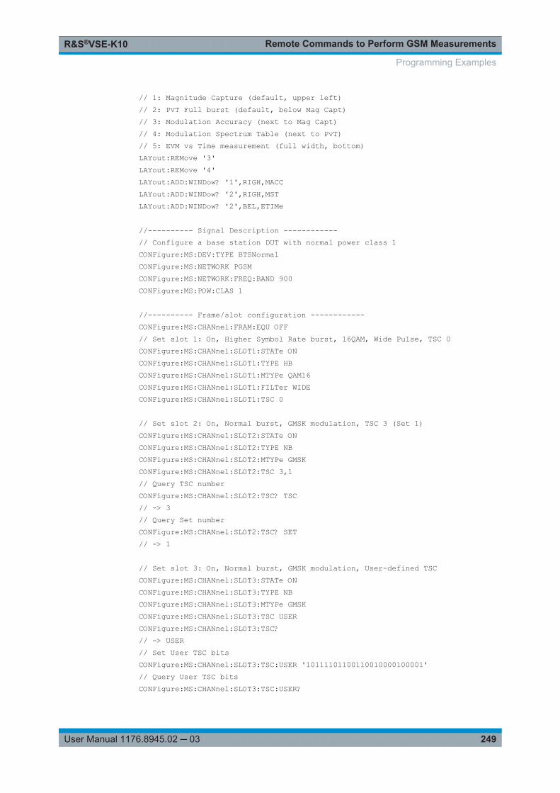
Remote Commands to Perform GSM MeasurementsR&S®VSE-K10
249User Manual 1176.8945.02 ─ 03
// 1: Magnitude Capture (default, upper left)// 2: PvT Full burst (default, below Mag Capt)// 3: Modulation Accuracy (next to Mag Capt)// 4: Modulation Spectrum Table (next to PvT)// 5: EVM vs Time measurement (full width, bottom)LAYout:REMove '3'LAYout:REMove '4'LAYout:ADD:WINDow? '1',RIGH,MACCLAYout:ADD:WINDow? '2',RIGH,MSTLAYout:ADD:WINDow? '2',BEL,ETIMe
//---------- Signal Description ------------// Configure a base station DUT with normal power class 1CONFigure:MS:DEV:TYPE BTSNormalCONFigure:MS:NETWORK PGSMCONFigure:MS:NETWORK:FREQ:BAND 900CONFigure:MS:POW:CLAS 1
//---------- Frame/slot configuration ------------CONFigure:MS:CHANnel:FRAM:EQU OFF// Set slot 1: On, Higher Symbol Rate burst, 16QAM, Wide Pulse, TSC 0CONFigure:MS:CHANnel:SLOT1:STATe ONCONFigure:MS:CHANnel:SLOT1:TYPE HBCONFigure:MS:CHANnel:SLOT1:MTYPe QAM16CONFigure:MS:CHANnel:SLOT1:FILTer WIDECONFigure:MS:CHANnel:SLOT1:TSC 0
// Set slot 2: On, Normal burst, GMSK modulation, TSC 3 (Set 1)CONFigure:MS:CHANnel:SLOT2:STATe ONCONFigure:MS:CHANnel:SLOT2:TYPE NBCONFigure:MS:CHANnel:SLOT2:MTYPe GMSKCONFigure:MS:CHANnel:SLOT2:TSC 3,1// Query TSC numberCONFigure:MS:CHANnel:SLOT2:TSC? TSC// -> 3// Query Set numberCONFigure:MS:CHANnel:SLOT2:TSC? SET// -> 1
// Set slot 3: On, Normal burst, GMSK modulation, User-defined TSCCONFigure:MS:CHANnel:SLOT3:STATe ONCONFigure:MS:CHANnel:SLOT3:TYPE NBCONFigure:MS:CHANnel:SLOT3:MTYPe GMSKCONFigure:MS:CHANnel:SLOT3:TSC USERCONFigure:MS:CHANnel:SLOT3:TSC?// -> USER// Set User TSC bitsCONFigure:MS:CHANnel:SLOT3:TSC:USER '10111101100110010000100001'// Query User TSC bitsCONFigure:MS:CHANnel:SLOT3:TSC:USER?
Programming Examples
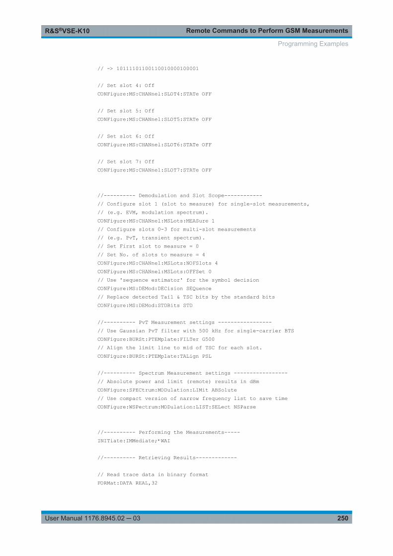
Remote Commands to Perform GSM MeasurementsR&S®VSE-K10
250User Manual 1176.8945.02 ─ 03
// -> 10111101100110010000100001
// Set slot 4: OffCONFigure:MS:CHANnel:SLOT4:STATe OFF
// Set slot 5: OffCONFigure:MS:CHANnel:SLOT5:STATe OFF
// Set slot 6: OffCONFigure:MS:CHANnel:SLOT6:STATe OFF
// Set slot 7: OffCONFigure:MS:CHANnel:SLOT7:STATe OFF
//---------- Demodulation and Slot Scope------------// Configure slot 1 (slot to measure) for single-slot measurements,// (e.g. EVM, modulation spectrum).CONFigure:MS:CHANnel:MSLots:MEASure 1// Configure slots 0-3 for multi-slot measurements// (e.g. PvT, transient spectrum).// Set First slot to measure = 0// Set No. of slots to measure = 4CONFigure:MS:CHANnel:MSLots:NOFSlots 4CONFigure:MS:CHANnel:MSLots:OFFSet 0// Use 'sequence estimator' for the symbol decisionCONFigure:MS:DEMod:DECision SEQuence// Replace detected Tail & TSC bits by the standard bitsCONFigure:MS:DEMod:STDBits STD
//---------- PvT Measurement settings -----------------// Use Gaussian PvT filter with 500 kHz for single-carrier BTSCONFigure:BURSt:PTEMplate:FILTer G500// Align the limit line to mid of TSC for each slot.CONFigure:BURSt:PTEMplate:TALign PSL
//---------- Spectrum Measurement settings -----------------// Absolute power and limit (remote) results in dBmCONFigure:SPECtrum:MODulation:LIMit ABSolute// Use compact version of narrow frequency list to save timeCONFigure:WSPectrum:MODulation:LIST:SELect NSParse
//---------- Performing the Measurements-----INITiate:IMMediate;*WAI
//---------- Retrieving Results-------------
// Read trace data in binary formatFORMat:DATA REAL,32
Programming Examples
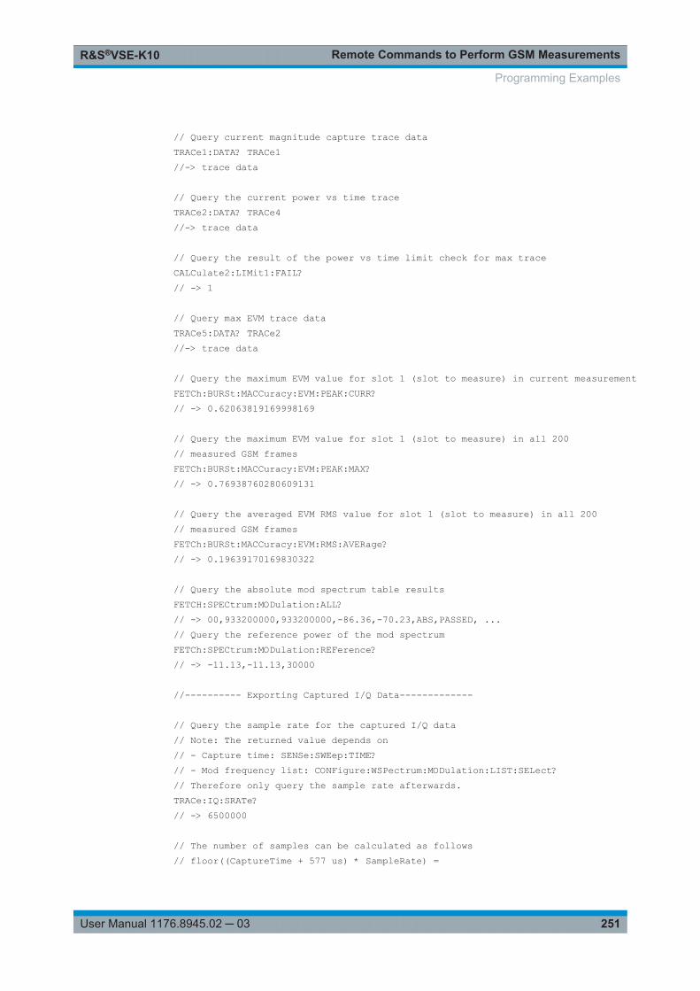
Remote Commands to Perform GSM MeasurementsR&S®VSE-K10
251User Manual 1176.8945.02 ─ 03
// Query current magnitude capture trace dataTRACe1:DATA? TRACe1//-> trace data
// Query the current power vs time traceTRACe2:DATA? TRACe4//-> trace data
// Query the result of the power vs time limit check for max traceCALCulate2:LIMit1:FAIL?// -> 1
// Query max EVM trace dataTRACe5:DATA? TRACe2//-> trace data
// Query the maximum EVM value for slot 1 (slot to measure) in current measurementFETCh:BURSt:MACCuracy:EVM:PEAK:CURR?// -> 0.62063819169998169
// Query the maximum EVM value for slot 1 (slot to measure) in all 200// measured GSM framesFETCh:BURSt:MACCuracy:EVM:PEAK:MAX?// -> 0.76938760280609131
// Query the averaged EVM RMS value for slot 1 (slot to measure) in all 200// measured GSM framesFETCh:BURSt:MACCuracy:EVM:RMS:AVERage?// -> 0.19639170169830322
// Query the absolute mod spectrum table resultsFETCH:SPECtrum:MODulation:ALL?// -> 00,933200000,933200000,-86.36,-70.23,ABS,PASSED, ...// Query the reference power of the mod spectrumFETCh:SPECtrum:MODulation:REFerence?// -> -11.13,-11.13,30000
//---------- Exporting Captured I/Q Data-------------
// Query the sample rate for the captured I/Q data// Note: The returned value depends on// - Capture time: SENSe:SWEep:TIME?// - Mod frequency list: CONFigure:WSPectrum:MODulation:LIST:SELect?// Therefore only query the sample rate afterwards.TRACe:IQ:SRATe?// -> 6500000
// The number of samples can be calculated as follows// floor((CaptureTime + 577 us) * SampleRate) =
Programming Examples
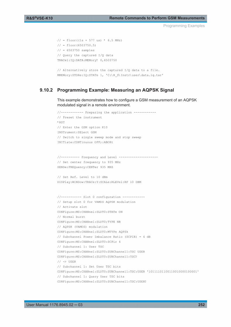
Remote Commands to Perform GSM MeasurementsR&S®VSE-K10
252User Manual 1176.8945.02 ─ 03
// = floor((1s + 577 us) * 6.5 MHz)// = floor(6503750.5)// = 6503750 samples// Query the captured I/Q dataTRACe1:IQ:DATA:MEMory? 0,6503750
// Alternatively store the captured I/Q data to a file.MMEMory:STORe:IQ:STATe 1, 'C:\R_S\Instr\user\data.iq.tar'
9.10.2 Programming Example: Measuring an AQPSK Signal
This example demonstrates how to configure a GSM measurement of an AQPSKmodulated signal in a remote environment.
//------------ Preparing the application ------------// Preset the instrument*RST// Enter the GSM option K10INSTrument:SELect GSM// Switch to single sweep mode and stop sweepINITiate:CONTinuous OFF;:ABORt
//---------- Frequency and Level ---------------------// Set center frequency to 935 MHzSENSe:FREQuency:CENTer 935 MHZ
// Set Ref. Level to 10 dBmDISPlay:WINDow:TRACe:Y:SCALe:RLEVel:RF 10 DBM
//----------- Slot 0 configuration ------------// Setup slot 0 for VAMOS AQPSK modulation// Activate slotCONFigure:MS:CHANnel:SLOT0:STATe ON// Normal burstCONFigure:MS:CHANnel:SLOT0:TYPE NB// AQPSK (VAMOS) modulationCONFigure:MS:CHANnel:SLOT0:MTYPe AQPSk// Subchannel Power Imbalance Ratio (SCPIR) = 4 dBCONFigure:MS:CHANnel:SLOT0:SCPir 4// Subchannel 1: User TSCCONFigure:MS:CHANnel:SLOT0:SUBChannel1:TSC USERCONFigure:MS:CHANnel:SLOT0:SUBChannel1:TSC?// -> USER// Subchannel 1: Set User TSC bitsCONFigure:MS:CHANnel:SLOT0:SUBChannel1:TSC:USER '10111101100110010000100001'// Subchannel 1: Query User TSC bitsCONFigure:MS:CHANnel:SLOT0:SUBChannel1:TSC:USER?
Programming Examples
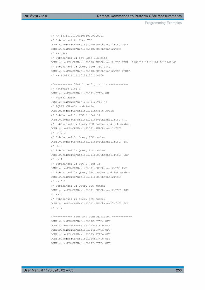
Remote Commands to Perform GSM MeasurementsR&S®VSE-K10
253User Manual 1176.8945.02 ─ 03
// -> 10111101100110010000100001// Subchannel 2: User TSCCONFigure:MS:CHANnel:SLOT0:SUBChannel2:TSC USERCONFigure:MS:CHANnel:SLOT0:SUBChannel2:TSC?// -> USER// Subchannel 2: Set User TSC bitsCONFigure:MS:CHANnel:SLOT0:SUBChannel2:TSC:USER '11010111111101011001110100'// Subchannel 2: Query User TSC bitsCONFigure:MS:CHANnel:SLOT0:SUBChannel2:TSC:USER?// -> 11010111111101011001110100
//----------- Slot 1 configuration ------------// Activate slot 1CONFigure:MS:CHANnel:SLOT1:STATe ON// Normal BurstCONFigure:MS:CHANnel:SLOT1:TYPE NB// AQPSK (VAMOS) modulationCONFigure:MS:CHANnel:SLOT1:MTYPe AQPSk// Subchannel 1: TSC 0 (Set 1)CONFigure:MS:CHANnel:SLOT1:SUBChannel1:TSC 0,1// Subchannel 1: Query TSC number and Set numberCONFigure:MS:CHANnel:SLOT1:SUBChannel1:TSC?// -> 0,1// Subchannel 1: Query TSC numberCONFigure:MS:CHANnel:SLOT1:SUBChannel1:TSC? TSC// -> 0// Subchannel 1: Query Set numberCONFigure:MS:CHANnel:SLOT1:SUBChannel1:TSC? SET// -> 1// Subchannel 2: TSC 0 (Set 1)CONFigure:MS:CHANnel:SLOT1:SUBChannel2:TSC 0,2// Subchannel 2: Query TSC number and Set numberCONFigure:MS:CHANnel:SLOT1:SUBChannel2:TSC?// -> 0,2// Subchannel 2: Query TSC numberCONFigure:MS:CHANnel:SLOT1:SUBChannel2:TSC? TSC// -> 0// Subchannel 2: Query Set numberCONFigure:MS:CHANnel:SLOT1:SUBChannel2:TSC? SET// -> 2
//----------- Slot 2-7 configuration ------------CONFigure:MS:CHANnel:SLOT2:STATe OFFCONFigure:MS:CHANnel:SLOT3:STATe OFFCONFigure:MS:CHANnel:SLOT4:STATe OFFCONFigure:MS:CHANnel:SLOT5:STATe OFFCONFigure:MS:CHANnel:SLOT6:STATe OFFCONFigure:MS:CHANnel:SLOT7:STATe OFF
Programming Examples
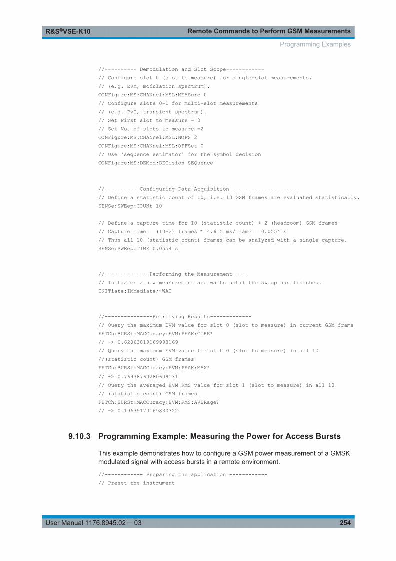
Remote Commands to Perform GSM MeasurementsR&S®VSE-K10
254User Manual 1176.8945.02 ─ 03
//---------- Demodulation and Slot Scope------------// Configure slot 0 (slot to measure) for single-slot measurements,// (e.g. EVM, modulation spectrum).CONFigure:MS:CHANnel:MSL:MEASure 0// Configure slots 0-1 for multi-slot measurements// (e.g. PvT, transient spectrum).// Set First slot to measure = 0// Set No. of slots to measure =2CONFigure:MS:CHANnel:MSL:NOFS 2CONFigure:MS:CHANnel:MSL:OFFSet 0// Use 'sequence estimator' for the symbol decisionCONFigure:MS:DEMod:DECision SEQuence
//---------- Configuring Data Acquisition ---------------------// Define a statistic count of 10, i.e. 10 GSM frames are evaluated statistically.SENSe:SWEep:COUNt 10
// Define a capture time for 10 (statistic count) + 2 (headroom) GSM frames// Capture Time = (10+2) frames * 4.615 ms/frame = 0.0554 s// Thus all 10 (statistic count) frames can be analyzed with a single capture.SENSe:SWEep:TIME 0.0554 s
//--------------Performing the Measurement-----// Initiates a new measurement and waits until the sweep has finished.INITiate:IMMediate;*WAI
//---------------Retrieving Results-------------// Query the maximum EVM value for slot 0 (slot to measure) in current GSM frameFETCh:BURSt:MACCuracy:EVM:PEAK:CURR?// -> 0.62063819169998169// Query the maximum EVM value for slot 0 (slot to measure) in all 10 //(statistic count) GSM framesFETCh:BURSt:MACCuracy:EVM:PEAK:MAX?// -> 0.76938760280609131// Query the averaged EVM RMS value for slot 1 (slot to measure) in all 10// (statistic count) GSM framesFETCh:BURSt:MACCuracy:EVM:RMS:AVERage?// -> 0.19639170169830322
9.10.3 Programming Example: Measuring the Power for Access Bursts
This example demonstrates how to configure a GSM power measurement of a GMSKmodulated signal with access bursts in a remote environment.
//------------ Preparing the application ------------// Preset the instrument
Programming Examples
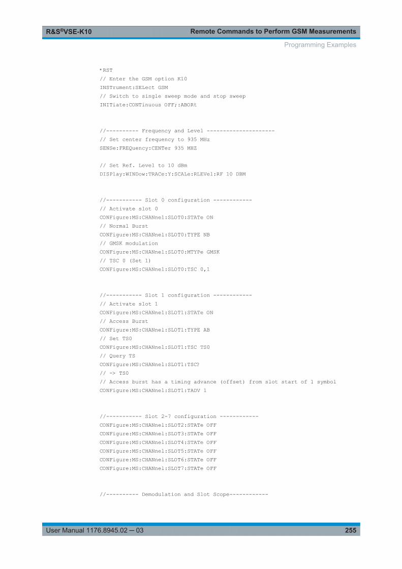
Remote Commands to Perform GSM MeasurementsR&S®VSE-K10
255User Manual 1176.8945.02 ─ 03
*RST// Enter the GSM option K10INSTrument:SELect GSM// Switch to single sweep mode and stop sweepINITiate:CONTinuous OFF;:ABORt
//---------- Frequency and Level ---------------------// Set center frequency to 935 MHzSENSe:FREQuency:CENTer 935 MHZ
// Set Ref. Level to 10 dBmDISPlay:WINDow:TRACe:Y:SCALe:RLEVel:RF 10 DBM
//----------- Slot 0 configuration ------------// Activate slot 0CONFigure:MS:CHANnel:SLOT0:STATe ON// Normal BurstCONFigure:MS:CHANnel:SLOT0:TYPE NB// GMSK modulationCONFigure:MS:CHANnel:SLOT0:MTYPe GMSK// TSC 0 (Set 1)CONFigure:MS:CHANnel:SLOT0:TSC 0,1
//----------- Slot 1 configuration ------------// Activate slot 1CONFigure:MS:CHANnel:SLOT1:STATe ON// Access BurstCONFigure:MS:CHANnel:SLOT1:TYPE AB// Set TS0CONFigure:MS:CHANnel:SLOT1:TSC TS0// Query TSCONFigure:MS:CHANnel:SLOT1:TSC?// -> TS0// Access burst has a timing advance (offset) from slot start of 1 symbolCONFigure:MS:CHANnel:SLOT1:TADV 1
//----------- Slot 2-7 configuration ------------CONFigure:MS:CHANnel:SLOT2:STATe OFFCONFigure:MS:CHANnel:SLOT3:STATe OFFCONFigure:MS:CHANnel:SLOT4:STATe OFFCONFigure:MS:CHANnel:SLOT5:STATe OFFCONFigure:MS:CHANnel:SLOT6:STATe OFFCONFigure:MS:CHANnel:SLOT7:STATe OFF
//---------- Demodulation and Slot Scope------------
Programming Examples
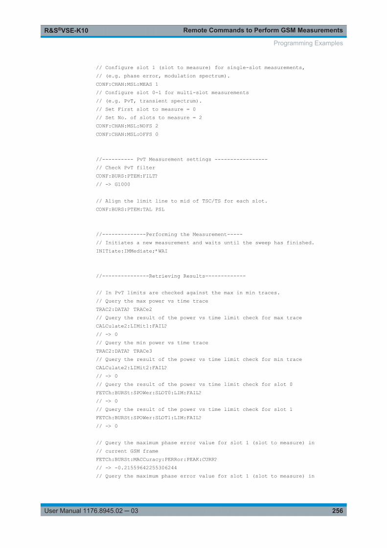
Remote Commands to Perform GSM MeasurementsR&S®VSE-K10
256User Manual 1176.8945.02 ─ 03
// Configure slot 1 (slot to measure) for single-slot measurements,// (e.g. phase error, modulation spectrum).CONF:CHAN:MSL:MEAS 1// Configure slot 0-1 for multi-slot measurements// (e.g. PvT, transient spectrum).// Set First slot to measure = 0// Set No. of slots to measure = 2CONF:CHAN:MSL:NOFS 2CONF:CHAN:MSL:OFFS 0
//---------- PvT Measurement settings -----------------// Check PvT filterCONF:BURS:PTEM:FILT?// -> G1000
// Align the limit line to mid of TSC/TS for each slot.CONF:BURS:PTEM:TAL PSL
//--------------Performing the Measurement-----// Initiates a new measurement and waits until the sweep has finished.INITiate:IMMediate;*WAI
//---------------Retrieving Results-------------
// In PvT limits are checked against the max in min traces.// Query the max power vs time traceTRAC2:DATA? TRACe2// Query the result of the power vs time limit check for max traceCALCulate2:LIMit1:FAIL?// -> 0// Query the min power vs time traceTRAC2:DATA? TRACe3// Query the result of the power vs time limit check for min traceCALCulate2:LIMit2:FAIL?// -> 0// Query the result of the power vs time limit check for slot 0FETCh:BURSt:SPOWer:SLOT0:LIM:FAIL?// -> 0// Query the result of the power vs time limit check for slot 1FETCh:BURSt:SPOWer:SLOT1:LIM:FAIL?// -> 0
// Query the maximum phase error value for slot 1 (slot to measure) in// current GSM frameFETCh:BURSt:MACCuracy:PERRor:PEAK:CURR?// -> -0.21559642255306244// Query the maximum phase error value for slot 1 (slot to measure) in
Programming Examples
Remote Commands to Perform GSM MeasurementsR&S®VSE-K10
257User Manual 1176.8945.02 ─ 03
// all 200 GSM framesFETCh:BURSt:MACCuracy:PERRor:PEAK:MAX?// -> 0.35961171984672546// Query the averaged phase error RMS value for slot 1 (slot to measure) in// all 200 GSM framesFETCh:BURSt:MACCuracy:PERRor:RMS:AVERage?// -> 0.082186274230480194
9.10.4 Programming Example: Measuring Statistics
This example demonstrates how to determine statistical values for a measurement in aremote environment.
-----------Configuring the measurement ------------*RST//Reset the instrumentCALC:MARK:FUNC:POW:SEL OBW//Activate occupied bandwidth measurement.
--------------Performing the Measurement-----INIT:CONT OFF//Selects single sweep mode.INIT;*WAI//Initiates a new measurement and waits until the sweep has finished.
---------------Retrieving Results-------------CALC:MARK:FUNC:POW:RES? OBW//Returns the results for the OBW measurement.
Programming Examples
Annex: ReferenceR&S®VSE-K10
258User Manual 1176.8945.02 ─ 03
AnnexA Annex: ReferenceA.1 List of abbreviations................................................................................................. 258
A.2 Menu Reference........................................................................................................ 259
A.2.1 Common R&S VSE Menus......................................................................................... 259
A.2.2 GSM Measurements Menus....................................................................................... 261
A.2.3 Reference of Toolbar Functions..................................................................................263
A.1 List of abbreviations
16QAM 16-ary Quadrature Amplitude Modulation
32QAM 32-ary Quadrature Amplitude Modulation
3GPP 3rd Generation Partnership Project
8PSK Phase Shift Keying with 8 phase states
AQPSK Adaptive Quadrature Amplitude Modulation
ARFCN Absolute Radio Frequency Channel Number
BTS Base Transceiver Station
DL Downlink (MS to BTS)
DUT Device Under Test
EDGE Enhanced Data Rates for GSM Evolution
EGPRS Enhanced General Packet Radio, synonym for EDGE.
EGPRS2 Enhanced General Packet Radio and support of additional modulation/codingschemes and higher symbol rate.
FDMA Frequency Division Multiplex Access
GMSK Gaussian Minimum Shift Keying
GPRS General Packet Radio Service
GSM Global System for Mobile Communication
HSCSD High-Speed Circuit-Switch Data
IF Intermediate Frequency
MS Mobile Station
NSP Normal Symbol Period
PCL Power Control Level
List of abbreviations
Annex: ReferenceR&S®VSE-K10
259User Manual 1176.8945.02 ─ 03
PDF Probability Density Function
PvT Power vs Time
QPSK Quadrature Phase Shift Keying
SCPIR Subchannel Power Imbalance Ratio
SFH Slow Frequency Hopping
TDMA Time Division Multiplex Access
TSC Training Sequence Code
UL Uplink (BTS to MS)
VAMOS Voice services over Adaptive Multi-user Channels on One Slot
YIG Yttrium Iron Garnet
A.2 Menu Reference
Most functions in the R&S VSE are available from the menus.
● Common R&S VSE Menus................................................................................... 259● GSM Measurements Menus................................................................................. 261● Reference of Toolbar Functions............................................................................263
A.2.1 Common R&S VSE Menus
The following menus provide basic functions for all applications:
● File Menu.............................................................................................................. 259● Window Menu....................................................................................................... 261● Help Menu.............................................................................................................261
A.2.1.1 File Menu
The "File" menu includes all functionality directly related to any file operations, printingor setting up general parameters.
Menu item Correspond-ing icon intoolbar
Description
Save Saves the current software configuration to a file
Recall Recalls a saved software configuration from a file
Save IQ Recording - Saves the recorded I/Q data from a measurement channel to afile
Recall IQ Recording - Loads the recorded I/Q data from a file
Menu Reference
Annex: ReferenceR&S®VSE-K10
260User Manual 1176.8945.02 ─ 03
Menu item Correspond-ing icon intoolbar
Description
Measurement Group > - Configures measurement channels and groups
> New Group - Inserts a new group in the measurement sequence
> Rename Group - Changes the name of the selected group
> New MeasurementChannel
- Inserts a new channel in the selected group
> Replace Measure-ment Channel
- Replaces the currently selected channel by the selected applica-tion.
> Rename Measure-ment Channel
- Changes the name of the selected channel.
> Delete Current Mea-surement Channel
- Deletes the currently selected channel.
> Measurement GroupSetup
- Displays the "Measurement Group Setup" tool window.
Instruments > - Configures instruments to be used for input to the R&S VSE soft-ware
> New - Creates a new instrument configuration
> Search - Searches for connected instruments in the network
> Delete All - Deletes all current instrument configurations
> Setup - Hides or displays the "Instrument" tool window
Preset > - Restores stored settings
> Selected Channel - Restores the default software configuration for an individualchannel
> All - Restores the default software configuration globally for the entiresoftware
> All & Delete Instru-ments
Restores the default software configuration globally for the entiresoftware and deletes all instrument configurations
> Reset VSE Layout - Restores the default layout of windows, toolbars etc. in theR&S VSE software
Preferences > - Configures global software settings
> General -
> Displayed Items - Hides or shows individual screen elements
> Theme & Color - Configures the style of individual screen elements
> Network & Remote - Configures the network settings and remote access to or fromother devices
> Recording - Configures general recording parameters
Print - Opens "Print" dialog to print selected measurement results
Exit - Closes the R&S VSE software
Menu Reference
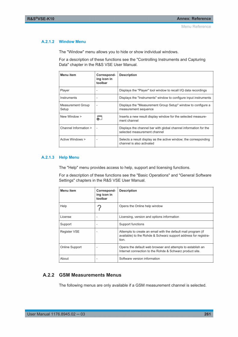
Annex: ReferenceR&S®VSE-K10
261User Manual 1176.8945.02 ─ 03
A.2.1.2 Window Menu
The "Window" menu allows you to hide or show individual windows.
For a description of these functions see the "Controlling Instruments and CapturingData" chapter in the R&S VSE User Manual.
Menu item Correspond-ing icon intoolbar
Description
Player - Displays the "Player" tool window to recall I/Q data recordings
Instruments - Displays the "Instruments" window to configure input instruments
Measurement GroupSetup
- Displays the "Measurement Group Setup" window to configure ameasurement sequence
New Window > Inserts a new result display window for the selected measure-ment channel
Channel Information > - Displays the channel bar with global channel information for theselected measurement channel
Active Windows > - Selects a result display as the active window; the correspondingchannel is also activated
A.2.1.3 Help Menu
The "Help" menu provides access to help, support and licensing functions.
For a description of these functions see the "Basic Operations" and "General SoftwareSettings" chapters in the R&S VSE User Manual.
Menu item Correspond-ing icon intoolbar
Description
Help Opens the Online help window
License - Licensing, version and options information
Support - Support functions
Register VSE - Attempts to create an email with the default mail program (ifavailable) to the Rohde & Schwarz support address for registra-tion.
Online Support - Opens the default web browser and attempts to establish anInternet connection to the Rohde & Schwarz product site.
About - Software version information
A.2.2 GSM Measurements Menus
The following menus are only available if a GSM measurement channel is selected.
Menu Reference
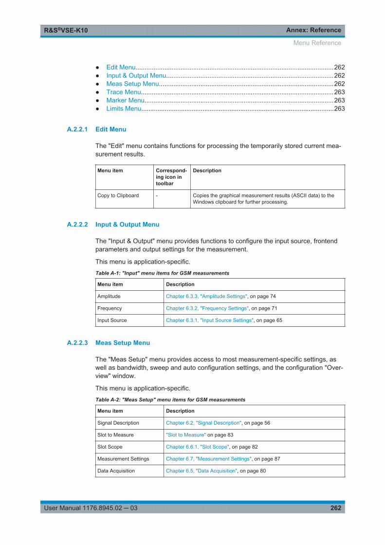
Annex: ReferenceR&S®VSE-K10
262User Manual 1176.8945.02 ─ 03
● Edit Menu..............................................................................................................262● Input & Output Menu.............................................................................................262● Meas Setup Menu.................................................................................................262● Trace Menu...........................................................................................................263● Marker Menu.........................................................................................................263● Limits Menu...........................................................................................................263
A.2.2.1 Edit Menu
The "Edit" menu contains functions for processing the temporarily stored current mea-surement results.
Menu item Correspond-ing icon intoolbar
Description
Copy to Clipboard - Copies the graphical measurement results (ASCII data) to theWindows clipboard for further processing.
A.2.2.2 Input & Output Menu
The "Input & Output" menu provides functions to configure the input source, frontendparameters and output settings for the measurement.
This menu is application-specific.
Table A-1: "Input" menu items for GSM measurements
Menu item Description
Amplitude Chapter 6.3.3, "Amplitude Settings", on page 74
Frequency Chapter 6.3.2, "Frequency Settings", on page 71
Input Source Chapter 6.3.1, "Input Source Settings", on page 65
A.2.2.3 Meas Setup Menu
The "Meas Setup" menu provides access to most measurement-specific settings, aswell as bandwidth, sweep and auto configuration settings, and the configuration "Over-view" window.
This menu is application-specific.
Table A-2: "Meas Setup" menu items for GSM measurements
Menu item Description
Signal Description Chapter 6.2, "Signal Description", on page 56
Slot to Measure "Slot to Measure" on page 83
Slot Scope Chapter 6.6.1, "Slot Scope", on page 82
Measurement Settings Chapter 6.7, "Measurement Settings", on page 87
Data Acquisition Chapter 6.5, "Data Acquisition", on page 80
Menu Reference
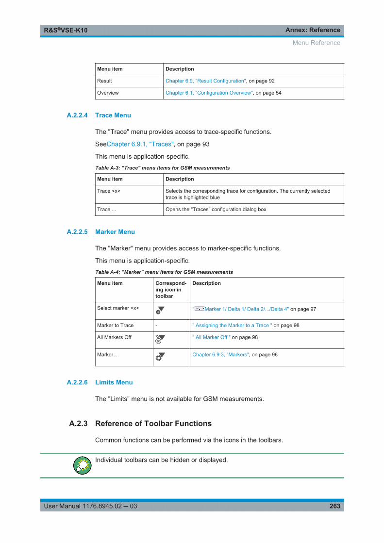
Annex: ReferenceR&S®VSE-K10
263User Manual 1176.8945.02 ─ 03
Menu item Description
Result Chapter 6.9, "Result Configuration", on page 92
Overview Chapter 6.1, "Configuration Overview", on page 54
A.2.2.4 Trace Menu
The "Trace" menu provides access to trace-specific functions.
SeeChapter 6.9.1, "Traces", on page 93
This menu is application-specific.
Table A-3: "Trace" menu items for GSM measurements
Menu item Description
Trace <x> Selects the corresponding trace for configuration. The currently selectedtrace is highlighted blue
Trace ... Opens the "Traces" configuration dialog box
A.2.2.5 Marker Menu
The "Marker" menu provides access to marker-specific functions.
This menu is application-specific.
Table A-4: "Marker" menu items for GSM measurements
Menu item Correspond-ing icon intoolbar
Description
Select marker <x> " Marker 1/ Delta 1/ Delta 2/.../Delta 4" on page 97
Marker to Trace - " Assigning the Marker to a Trace " on page 98
All Markers Off " All Marker Off " on page 98
Marker... Chapter 6.9.3, "Markers", on page 96
A.2.2.6 Limits Menu
The "Limits" menu is not available for GSM measurements.
A.2.3 Reference of Toolbar Functions
Common functions can be performed via the icons in the toolbars.
Individual toolbars can be hidden or displayed.
Menu Reference
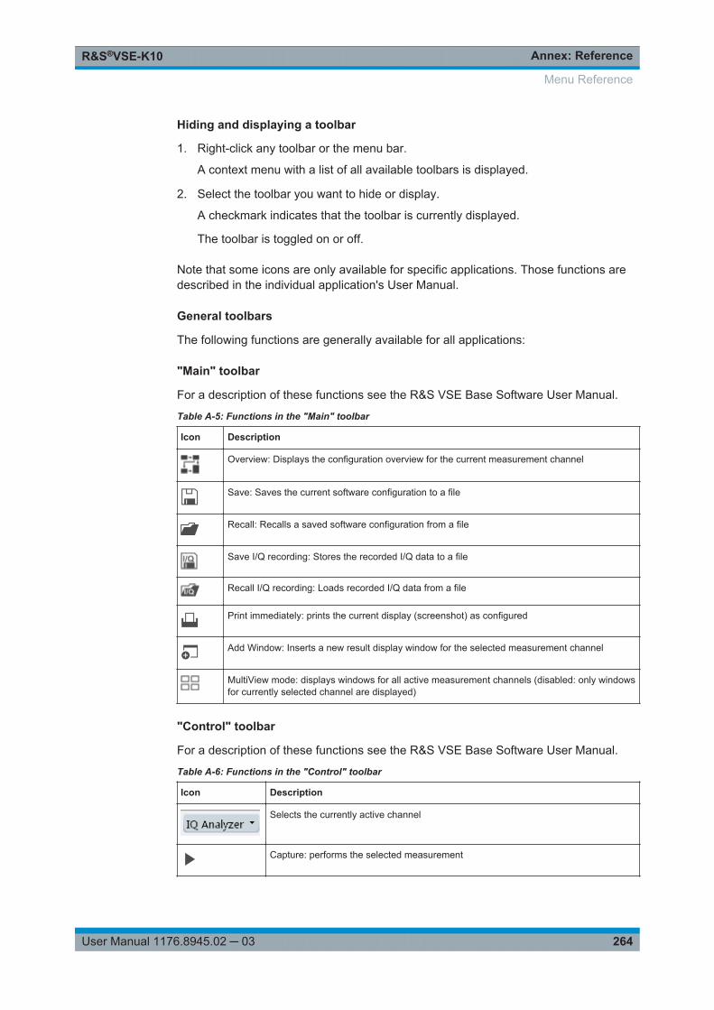
Annex: ReferenceR&S®VSE-K10
264User Manual 1176.8945.02 ─ 03
Hiding and displaying a toolbar
1. Right-click any toolbar or the menu bar.
A context menu with a list of all available toolbars is displayed.
2. Select the toolbar you want to hide or display.
A checkmark indicates that the toolbar is currently displayed.
The toolbar is toggled on or off.
Note that some icons are only available for specific applications. Those functions aredescribed in the individual application's User Manual.
General toolbars
The following functions are generally available for all applications:
"Main" toolbar
For a description of these functions see the R&S VSE Base Software User Manual.
Table A-5: Functions in the "Main" toolbar
Icon Description
Overview: Displays the configuration overview for the current measurement channel
Save: Saves the current software configuration to a file
Recall: Recalls a saved software configuration from a file
Save I/Q recording: Stores the recorded I/Q data to a file
Recall I/Q recording: Loads recorded I/Q data from a file
Print immediately: prints the current display (screenshot) as configured
Add Window: Inserts a new result display window for the selected measurement channel
MultiView mode: displays windows for all active measurement channels (disabled: only windowsfor currently selected channel are displayed)
"Control" toolbar
For a description of these functions see the R&S VSE Base Software User Manual.
Table A-6: Functions in the "Control" toolbar
Icon Description
Selects the currently active channel
Capture: performs the selected measurement
Menu Reference
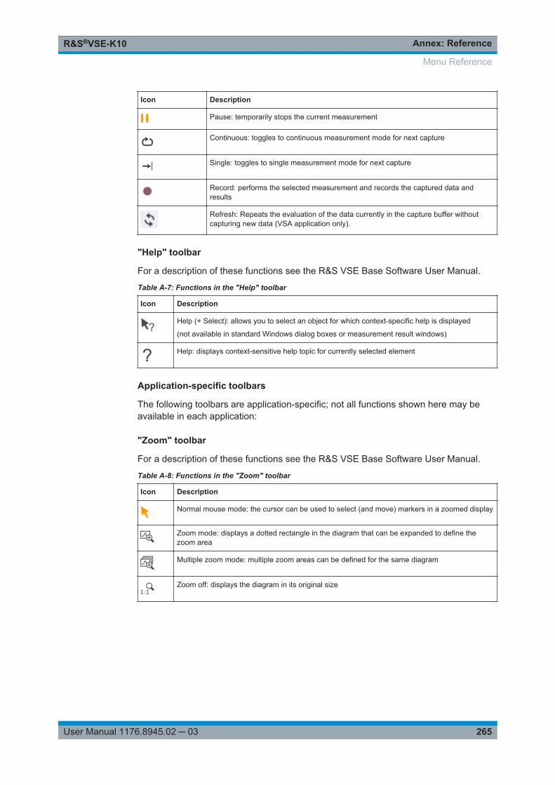
Annex: ReferenceR&S®VSE-K10
265User Manual 1176.8945.02 ─ 03
Icon Description
Pause: temporarily stops the current measurement
Continuous: toggles to continuous measurement mode for next capture
Single: toggles to single measurement mode for next capture
Record: performs the selected measurement and records the captured data andresults
Refresh: Repeats the evaluation of the data currently in the capture buffer withoutcapturing new data (VSA application only).
"Help" toolbar
For a description of these functions see the R&S VSE Base Software User Manual.
Table A-7: Functions in the "Help" toolbar
Icon Description
Help (+ Select): allows you to select an object for which context-specific help is displayed
(not available in standard Windows dialog boxes or measurement result windows)
Help: displays context-sensitive help topic for currently selected element
Application-specific toolbars
The following toolbars are application-specific; not all functions shown here may beavailable in each application:
"Zoom" toolbar
For a description of these functions see the R&S VSE Base Software User Manual.
Table A-8: Functions in the "Zoom" toolbar
Icon Description
Normal mouse mode: the cursor can be used to select (and move) markers in a zoomed display
Zoom mode: displays a dotted rectangle in the diagram that can be expanded to define thezoom area
Multiple zoom mode: multiple zoom areas can be defined for the same diagram
Zoom off: displays the diagram in its original size
Menu Reference
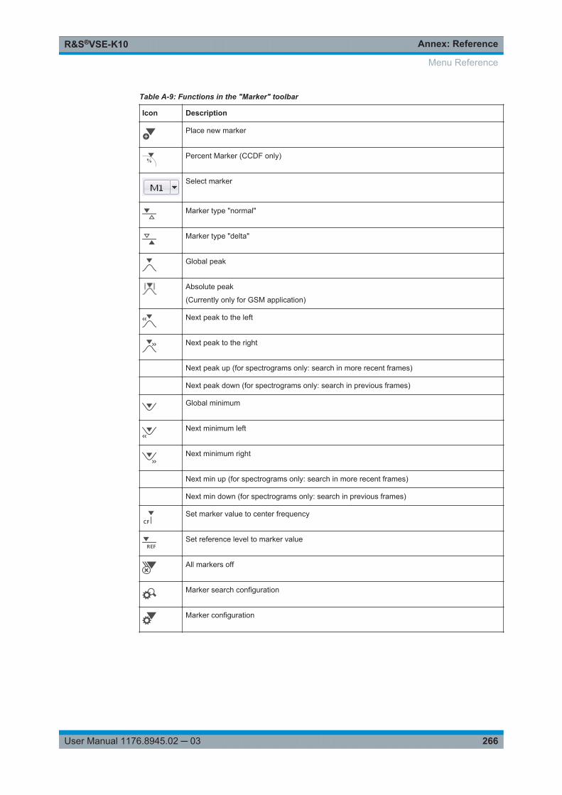
Annex: ReferenceR&S®VSE-K10
266User Manual 1176.8945.02 ─ 03
Table A-9: Functions in the "Marker" toolbar
Icon Description
Place new marker
%Percent Marker (CCDF only)
Select marker
Marker type "normal"
Marker type "delta"
Global peak
Absolute peak
(Currently only for GSM application)
Next peak to the left
Next peak to the right
Next peak up (for spectrograms only: search in more recent frames)
Next peak down (for spectrograms only: search in previous frames)
Global minimum
Next minimum left
Next minimum right
Next min up (for spectrograms only: search in more recent frames)
Next min down (for spectrograms only: search in previous frames)
Set marker value to center frequency
Set reference level to marker value
All markers off
Marker search configuration
Marker configuration
Menu Reference
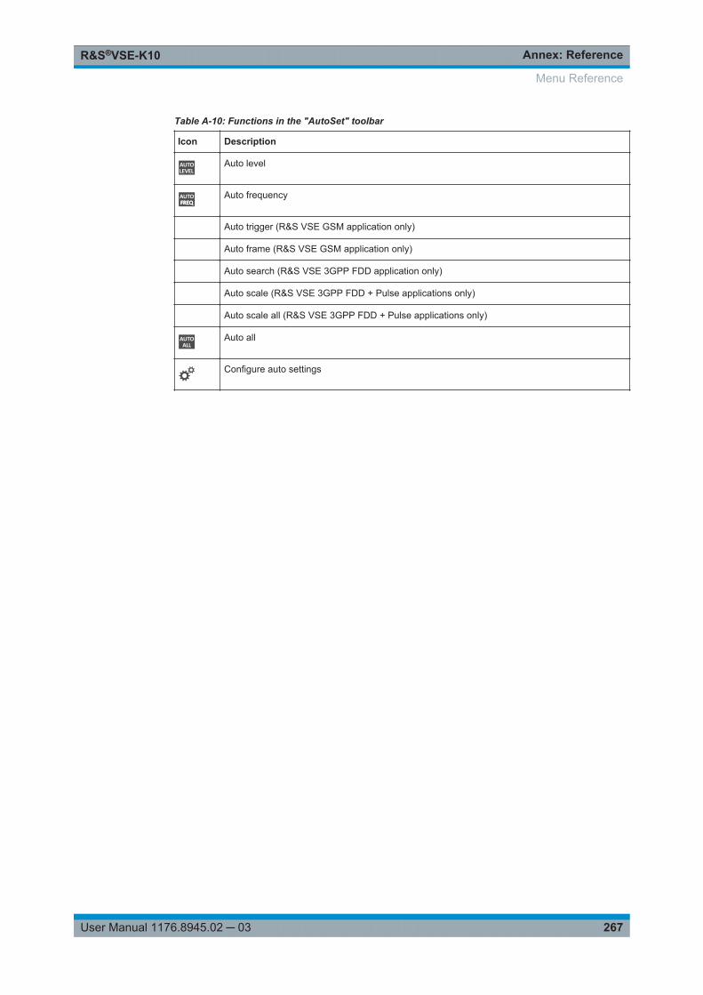
Annex: ReferenceR&S®VSE-K10
267User Manual 1176.8945.02 ─ 03
Table A-10: Functions in the "AutoSet" toolbar
Icon Description
Auto level
Auto frequency
Auto trigger (R&S VSE GSM application only)
Auto frame (R&S VSE GSM application only)
Auto search (R&S VSE 3GPP FDD application only)
Auto scale (R&S VSE 3GPP FDD + Pulse applications only)
Auto scale all (R&S VSE 3GPP FDD + Pulse applications only)
Auto all
Configure auto settings
Menu Reference
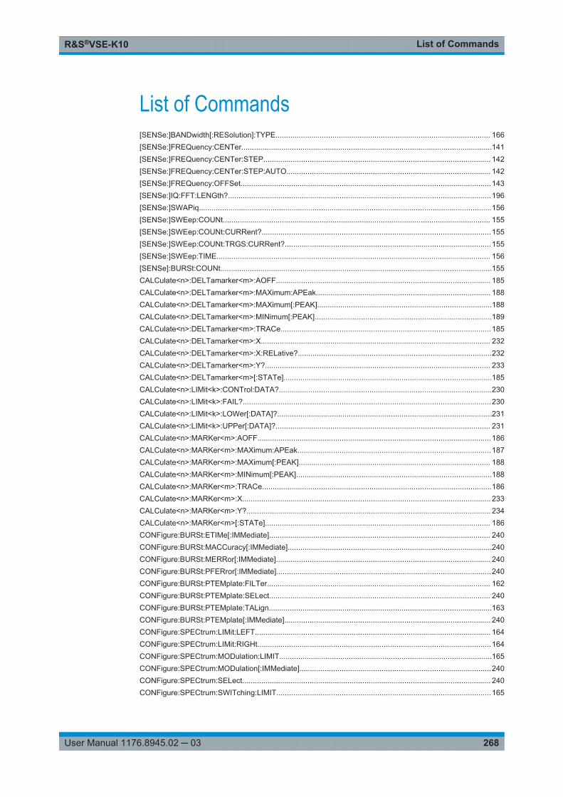
List of CommandsR&S®VSE-K10
268User Manual 1176.8945.02 ─ 03
List of Commands[SENSe:]BANDwidth[:RESolution]:TYPE...................................................................................................... 166[SENSe:]FREQuency:CENTer.......................................................................................................................141[SENSe:]FREQuency:CENTer:STEP............................................................................................................ 142[SENSe:]FREQuency:CENTer:STEP:AUTO................................................................................................. 142[SENSe:]FREQuency:OFFSet.......................................................................................................................143[SENSe:]IQ:FFT:LENGth?.............................................................................................................................196[SENSe:]SWAPiq...........................................................................................................................................156[SENSe:]SWEep:COUNt............................................................................................................................... 155[SENSe:]SWEep:COUNt:CURRent?.............................................................................................................155[SENSe:]SWEep:COUNt:TRGS:CURRent?..................................................................................................155[SENSe:]SWEep:TIME.................................................................................................................................. 156[SENSe]:BURSt:COUNt.................................................................................................................................155CALCulate<n>:DELTamarker<m>:AOFF...................................................................................................... 185CALCulate<n>:DELTamarker<m>:MAXimum:APEak................................................................................... 188CALCulate<n>:DELTamarker<m>:MAXimum[:PEAK]...................................................................................188CALCulate<n>:DELTamarker<m>:MINimum[:PEAK]....................................................................................189CALCulate<n>:DELTamarker<m>:TRACe....................................................................................................185CALCulate<n>:DELTamarker<m>:X............................................................................................................. 232CALCulate<n>:DELTamarker<m>:X:RELative?............................................................................................232CALCulate<n>:DELTamarker<m>:Y?........................................................................................................... 233CALCulate<n>:DELTamarker<m>[:STATe]...................................................................................................185CALCulate<n>:LIMit<k>:CONTrol:DATA?.....................................................................................................230CALCulate<n>:LIMit<k>:FAIL?......................................................................................................................230CALCulate<n>:LIMit<k>:LOWer[:DATA]?......................................................................................................231CALCulate<n>:LIMit<k>:UPPer[:DATA]?...................................................................................................... 231CALCulate<n>:MARKer<m>:AOFF...............................................................................................................186CALCulate<n>:MARKer<m>:MAXimum:APEak............................................................................................187CALCulate<n>:MARKer<m>:MAXimum[:PEAK]........................................................................................... 188CALCulate<n>:MARKer<m>:MINimum[:PEAK].............................................................................................188CALCulate<n>:MARKer<m>:TRACe.............................................................................................................186CALCulate<n>:MARKer<m>:X...................................................................................................................... 233CALCulate<n>:MARKer<m>:Y?.................................................................................................................... 234CALCulate<n>:MARKer<m>[:STATe]........................................................................................................... 186CONFigure:BURSt:ETIMe[:IMMediate]......................................................................................................... 240CONFigure:BURSt:MACCuracy[:IMMediate].................................................................................................240CONFigure:BURSt:MERRor[:IMMediate]...................................................................................................... 240CONFigure:BURSt:PFERror[:IMMediate]......................................................................................................240CONFigure:BURSt:PTEMplate:FILTer.......................................................................................................... 162CONFigure:BURSt:PTEMplate:SELect......................................................................................................... 240CONFigure:BURSt:PTEMplate:TALign..........................................................................................................163CONFigure:BURSt:PTEMplate[:IMMediate].................................................................................................. 240CONFigure:SPECtrum:LIMit:LEFT................................................................................................................ 164CONFigure:SPECtrum:LIMit:RIGHt...............................................................................................................164CONFigure:SPECtrum:MODulation:LIMIT.....................................................................................................165CONFigure:SPECtrum:MODulation[:IMMediate]...........................................................................................240CONFigure:SPECtrum:SELect...................................................................................................................... 240CONFigure:SPECtrum:SWITching:LIMIT......................................................................................................165
List of CommandsR&S®VSE-K10
269User Manual 1176.8945.02 ─ 03
CONFigure:SPECtrum:SWITching:TYPE......................................................................................................165CONFigure:SPECtrum:SWITching[:IMMediate]............................................................................................ 240CONFigure:TRGS:ADPSize.......................................................................................................................... 167CONFigure:TRGS:NOFBins.......................................................................................................................... 167CONFigure:TRGS[:IMMediate]......................................................................................................................240CONFigure:WSPectrum:MODulation:LIMIT.................................................................................................. 245CONFigure:WSPectrum:MODulation:LIST:SELect....................................................................................... 166CONFigure:WSPectrum:MODulation[:IMMediate].........................................................................................240CONFigure[:MS]:ARFCn................................................................................................................................141CONFigure[:MS]:AUTO:FRAMe ONCE.........................................................................................................168CONFigure[:MS]:AUTO:LEVel ONCE........................................................................................................... 168CONFigure[:MS]:AUTO:TRIGger ONCE....................................................................................................... 168CONFigure[:MS]:BSEarch............................................................................................................................. 241CONFigure[:MS]:BSTHreshold......................................................................................................................241CONFigure[:MS]:CHANnel:FRAMe:EQUal....................................................................................................124CONFigure[:MS]:CHANnel:MSLots:MEASure...............................................................................................157CONFigure[:MS]:CHANnel:MSLots:NOFSlots...............................................................................................157CONFigure[:MS]:CHANnel:MSLots:OFFSet..................................................................................................158CONFigure[:MS]:CHANnel:SLOT<Number>:FILTer..................................................................................... 125CONFigure[:MS]:CHANnel:SLOT<Number>:MTYPe....................................................................................126CONFigure[:MS]:CHANnel:SLOT<Number>:TADVance...............................................................................128CONFigure[:MS]:CHANnel:SLOT<Number>:TYPE.......................................................................................131CONFigure[:MS]:CHANnel:SLOT<Number>[:STATe]...................................................................................126CONFigure[:MS]:CHANnel:SLOT<s>:SCPir..................................................................................................127CONFigure[:MS]:CHANnel:SLOT<s>:SUBChannel<ch>:TSC......................................................................128CONFigure[:MS]:CHANnel:SLOT<s>:SUBChannel<ch>:TSC:USER...........................................................127CONFigure[:MS]:CHANnel:SLOT<s>:TSC....................................................................................................129CONFigure[:MS]:CHANnel:SLOT<s>:TSC:USER.........................................................................................130CONFigure[:MS]:DEMod:DECision............................................................................................................... 160CONFigure[:MS]:DEMod:STDBits................................................................................................................. 161CONFigure[:MS]:DEVice:TYPE.....................................................................................................................120CONFigure[:MS]:MCARrier:ACTCarriers.......................................................................................................241CONFigure[:MS]:MCARrier:BTSClass...........................................................................................................242CONFigure[:MS]:MCARrier:CARRier<c>:FREQuency..................................................................................132CONFigure[:MS]:MCARrier:CARRier<c>:MTYPe......................................................................................... 132CONFigure[:MS]:MCARrier:CARRier<c>[:STATe]?...................................................................................... 132CONFigure[:MS]:MCARrier:FALLocation...................................................................................................... 133CONFigure[:MS]:MCARrier:FALLocation:NCONtiguous:GSACarrier............................................................134CONFigure[:MS]:MCARrier:FILTer................................................................................................................242CONFigure[:MS]:MCARrier:MCBTs...............................................................................................................243CONFigure[:MS]:MCARrier[:STATe]............................................................................................................. 243CONFigure[:MS]:MTYPe............................................................................................................................... 243CONFigure[:MS]:NETWork:FREQuency:BAND............................................................................................ 121CONFigure[:MS]:NETWork[:TYPE]............................................................................................................... 121CONFigure[:MS]:POWer:AUTO ONCE......................................................................................................... 244CONFigure[:MS]:POWer:CLASs................................................................................................................... 122CONFigure[:MS]:POWer:PCARrier:AUTO?.................................................................................................. 124CONFigure[:MS]:POWer:PCARrier?............................................................................................................. 123CONFigure[:MS]:SSEarch............................................................................................................................. 244CONFigure[:MS]:SYNC:IQCThreshold..........................................................................................................160
List of CommandsR&S®VSE-K10
270User Manual 1176.8945.02 ─ 03
CONFigure[:MS]:SYNC:MODE......................................................................................................................158CONFigure[:MS]:SYNC:ONLY.......................................................................................................................159DISPlay:FORMat........................................................................................................................................... 179DISPlay:MTABle............................................................................................................................................ 187DISPlay[:WINDow<n>]:SELect......................................................................................................................179DISPlay[:WINDow<n>]:TRACe<t>:MODE.....................................................................................................180DISPlay[:WINDow<n>]:TRACe<t>:Y[:SCALe]...............................................................................................144DISPlay[:WINDow<n>]:TRACe<t>:Y[:SCALe]:AUTO....................................................................................189DISPlay[:WINDow<n>]:TRACe<t>:Y[:SCALe]:MAXimum............................................................................. 190DISPlay[:WINDow<n>]:TRACe<t>:Y[:SCALe]:MINimum.............................................................................. 190DISPlay[:WINDow<n>]:TRACe<t>:Y[:SCALe]:PDIVision..............................................................................143DISPlay[:WINDow<n>]:TRACe<t>:Y[:SCALe]:PDIVision..............................................................................190DISPlay[:WINDow<n>]:TRACe<t>:Y[:SCALe]:RLEVel..................................................................................144DISPlay[:WINDow<n>]:TRACe<t>:Y[:SCALe]:RLEVel:OFFSet....................................................................144DISPlay[:WINDow<n>]:TRACe<t>:Y[:SCALe]:RPOSition.............................................................................191DISPlay[:WINDow<n>]:TRACe<t>:Y[:SCALe]:RVALue................................................................................ 191DISPlay[:WINDow<n>]:TRACe<t>:Y[:SCALe]:RVALue:MAXimum...............................................................192DISPlay[:WINDow<n>]:TRACe<t>:Y[:SCALe]:RVALue:MINimum................................................................192DISPlay[:WINDow<n>]:TRACe<t>[:STATe].................................................................................................. 180DISPlay[:WINDow<n>]:ZOOM:AREA............................................................................................................192DISPlay[:WINDow<n>]:ZOOM:MULTiple<zoom>:AREA...............................................................................193DISPlay[:WINDow<n>]:ZOOM:MULTiple<zoom>:STATe............................................................................. 194DISPlay[:WINDow<n>]:ZOOM[:STATe].........................................................................................................193FETCh:BURSt:PTEMplate:TRGS:AVERage?...............................................................................................228FETCh:BURSt:PTEMplate:TRGS:CURRent?............................................................................................... 228FETCh:BURSt:PTEMplate:TRGS:MAXimum?.............................................................................................. 228FETCh:BURSt:PTEMplate:TRGS:MINimum?............................................................................................... 228FETCh:BURSt:PTEMplate:TRGS:SDEViation?............................................................................................ 228FETCh:BURSt:SPOWer:SLOT<s>:ALL:AVERage?......................................................................................219FETCh:BURSt:SPOWer:SLOT<s>:ALL:CRESt?...........................................................................................219FETCh:BURSt:SPOWer:SLOT<s>:ALL:MAXimum?.....................................................................................220FETCh:BURSt:SPOWer:SLOT<s>:CURRent:AVERage?.............................................................................221FETCh:BURSt:SPOWer:SLOT<s>:CURRent:CRESt?..................................................................................222FETCh:BURSt:SPOWer:SLOT<s>:CURRent:MAXimum?............................................................................223FETCh:BURSt:SPOWer:SLOT<s>:DELTatosync?....................................................................................... 224FETCh:BURSt:SPOWer:SLOT<s>:LIMit:FAIL?.............................................................................................225FETCh:BURSt[:MACCuracy]:ADRoop:AVERage?........................................................................................209FETCh:BURSt[:MACCuracy]:ADRoop:CURRent?........................................................................................ 209FETCh:BURSt[:MACCuracy]:ADRoop:MAXimum?.......................................................................................209FETCh:BURSt[:MACCuracy]:ADRoop:SDEViation?..................................................................................... 209FETCh:BURSt[:MACCuracy]:ALL?................................................................................................................208FETCh:BURSt[:MACCuracy]:BPOWer:AVERage?....................................................................................... 209FETCh:BURSt[:MACCuracy]:BPOWer:CURRent?........................................................................................209FETCh:BURSt[:MACCuracy]:BPOWer:MAXimum?...................................................................................... 209FETCh:BURSt[:MACCuracy]:BPOWer:SDEViation?.....................................................................................209FETCh:BURSt[:MACCuracy]:FERRor:AVERage?........................................................................................ 245FETCh:BURSt[:MACCuracy]:FERRor:CURRent?.........................................................................................245FETCh:BURSt[:MACCuracy]:FERRor:MAXimum?........................................................................................245FETCh:BURSt[:MACCuracy]:FERRor:SDEViation?......................................................................................245FETCh:BURSt[:MACCuracy]:FREQuency:AVERage?..................................................................................211
List of CommandsR&S®VSE-K10
271User Manual 1176.8945.02 ─ 03
FETCh:BURSt[:MACCuracy]:FREQuency:CURRent?.................................................................................. 211FETCh:BURSt[:MACCuracy]:FREQuency:MAXimum?.................................................................................211FETCh:BURSt[:MACCuracy]:FREQuency:SDEViation?............................................................................... 211FETCh:BURSt[:MACCuracy]:IQIMbalance:AVERage?.................................................................................211FETCh:BURSt[:MACCuracy]:IQIMbalance:CURRent?................................................................................. 211FETCh:BURSt[:MACCuracy]:IQIMbalance:MAXimum?................................................................................ 211FETCh:BURSt[:MACCuracy]:IQIMbalance:SDEViation?.............................................................................. 211FETCh:BURSt[:MACCuracy]:IQOFfset:AVERage?.......................................................................................212FETCh:BURSt[:MACCuracy]:IQOFfset:CURRent?....................................................................................... 212FETCh:BURSt[:MACCuracy]:IQOFfset:MAXimum?......................................................................................212FETCh:BURSt[:MACCuracy]:IQOFfset:SDEViation?.................................................................................... 212FETCh:BURSt[:MACCuracy]:MERRor:PEAK:AVERage?.............................................................................212FETCh:BURSt[:MACCuracy]:MERRor:PEAK:CURRent?............................................................................. 212FETCh:BURSt[:MACCuracy]:MERRor:PEAK:MAXimum?............................................................................ 212FETCh:BURSt[:MACCuracy]:MERRor:PEAK:SDEViation?.......................................................................... 212FETCh:BURSt[:MACCuracy]:MERRor:RMS:AVERage?...............................................................................213FETCh:BURSt[:MACCuracy]:MERRor:RMS:CURRent?...............................................................................213FETCh:BURSt[:MACCuracy]:MERRor:RMS:MAXimum?..............................................................................213FETCh:BURSt[:MACCuracy]:MERRor:RMS:SDEViation?............................................................................213FETCh:BURSt[:MACCuracy]:OSUPpress:AVERage?.................................................................................. 213FETCh:BURSt[:MACCuracy]:OSUPpress:CURRent?...................................................................................213FETCh:BURSt[:MACCuracy]:OSUPpress:MAXimum?..................................................................................213FETCh:BURSt[:MACCuracy]:OSUPpress:SDEViation?................................................................................213FETCh:BURSt[:MACCuracy]:PERCentile:EVM?...........................................................................................214FETCh:BURSt[:MACCuracy]:PERCentile:MERRor?.....................................................................................214FETCh:BURSt[:MACCuracy]:PERCentile:PERRor?..................................................................................... 214FETCh:BURSt[:MACCuracy]:PERRor:PEAK:AVERage?..............................................................................215FETCh:BURSt[:MACCuracy]:PERRor:PEAK:CURRent?..............................................................................215FETCh:BURSt[:MACCuracy]:PERRor:PEAK:MAXimum?.............................................................................215FETCh:BURSt[:MACCuracy]:PERRor:PEAK:SDEViation?...........................................................................215FETCh:BURSt[:MACCuracy]:PERRor:RMS:AVERage?............................................................................... 215FETCh:BURSt[:MACCuracy]:PERRor:RMS:CURRent?................................................................................215FETCh:BURSt[:MACCuracy]:PERRor:RMS:MAXimum?.............................................................................. 215FETCh:BURSt[:MACCuracy]:PERRor:RMS:SDEViation?.............................................................................215FETCh:BURSt[:MACCuracy][:EVM]:PEAK:AVERage?.................................................................................210FETCh:BURSt[:MACCuracy][:EVM]:PEAK:CURRent?................................................................................. 210FETCh:BURSt[:MACCuracy][:EVM]:PEAK:MAXimum?................................................................................ 210FETCh:BURSt[:MACCuracy][:EVM]:PEAK:SDEViation?.............................................................................. 210FETCh:BURSt[:MACCuracy][:EVM]:RMS:AVERage?...................................................................................210FETCh:BURSt[:MACCuracy][:EVM]:RMS:CURRent?...................................................................................210FETCh:BURSt[:MACCuracy][:EVM]:RMS:MAXimum?..................................................................................210FETCh:BURSt[:MACCuracy][:EVM]:RMS:SDEViation?................................................................................210FETCh:MCAPture:SLOTs:MEASure?........................................................................................................... 204FETCh:MCAPture:SLOTs:SCOPe?...............................................................................................................204FETCh:SPECtrum:MODulation:REFerence?................................................................................................ 217FETCh:SPECtrum:MODulation[:ALL]?.......................................................................................................... 216FETCh:SPECtrum:SWITching:REFerence?..................................................................................................227FETCh:SPECtrum:SWITching[:ALL]?............................................................................................................226FETCh:WSPectrum:MODulation:REFerence?.............................................................................................. 246FETCh:WSPectrum:MODulation[:ALL]?........................................................................................................246
List of CommandsR&S®VSE-K10
272User Manual 1176.8945.02 ─ 03
FORMat:DEXPort:DSEParator...................................................................................................................... 183FORMat:DEXPort:DSEParator...................................................................................................................... 195FORMat:DEXPort:HEADer............................................................................................................................ 183FORMat:DEXPort:TRACes............................................................................................................................184FORMat[:DATA].............................................................................................................................................182FORMat[:DATA].............................................................................................................................................195INPut:ATTenuation........................................................................................................................................ 145INPut:ATTenuation:AUTO............................................................................................................................. 145INPut:COUPling.............................................................................................................................................135INPut:DPATh................................................................................................................................................. 135INPut:EATT....................................................................................................................................................146INPut:EATT:AUTO.........................................................................................................................................146INPut:EATT:STATe........................................................................................................................................146INPut:FILTer:HPASs[:STATe]........................................................................................................................135INPut:FILTer:YIG[:STATe].............................................................................................................................136INPut:GAIN:STATe........................................................................................................................................144INPut:GAIN[:VALue]...................................................................................................................................... 145INPut:IMPedance...........................................................................................................................................136INPut:RF:CAPM.............................................................................................................................................137INPut:SELect................................................................................................................................................. 137INPut<n>:ATTenuation:PROTection[:STATe]............................................................................................... 135INPut<n>:PRESelection:SET.........................................................................................................................136INPut<n>:PRESelection[:STATe].................................................................................................................. 137INPut<n>:TYPE............................................................................................................................................. 138INSTrument:BLOCk:CHANnel[:SETTings]:SOURce.....................................................................................138LAYout:ADD[:WINDow]?............................................................................................................................... 173LAYout:CATalog[:WINDow]?.........................................................................................................................175LAYout:GLOBal:ADD[:WINDow]?..................................................................................................................169LAYout:GLOBal:CATalog[:WINDow]?........................................................................................................... 171LAYout:GLOBal:IDENtify[:WINDow]?............................................................................................................171LAYout:GLOBal:REMove[:WINDow]............................................................................................................. 172LAYout:GLOBal:REPLace[:WINDow]............................................................................................................172LAYout:IDENtify[:WINDow]?..........................................................................................................................175LAYout:REMove[:WINDow]........................................................................................................................... 176LAYout:REPLace[:WINDow]..........................................................................................................................176LAYout:WINDow<n>:ADD?........................................................................................................................... 177LAYout:WINDow<n>:IDENtify?......................................................................................................................177LAYout:WINDow<n>:REMove.......................................................................................................................178LAYout:WINDow<n>:REPLace......................................................................................................................178LAYout:WINDow<n>:TYPe?..........................................................................................................................179MMEMory:STORe<n>:TRACe.......................................................................................................................184OUTPut:TRIGger<port>:DIRection................................................................................................................153OUTPut:TRIGger<port>:LEVel...................................................................................................................... 153OUTPut:TRIGger<port>:OTYPe....................................................................................................................153OUTPut:TRIGger<port>:PULSe:IMMediate...................................................................................................154OUTPut:TRIGger<port>:PULSe:LENGth.......................................................................................................154READ:AUTO:LEVTime?................................................................................................................................ 247READ:BURSt:PTEMplate:TRGS:AVERage?................................................................................................ 228READ:BURSt:PTEMplate:TRGS:CURRent?.................................................................................................228READ:BURSt:PTEMplate:TRGS:MAXimum?................................................................................................228
List of CommandsR&S®VSE-K10
273User Manual 1176.8945.02 ─ 03
READ:BURSt:PTEMplate:TRGS:MINimum?.................................................................................................229READ:BURSt:PTEMplate:TRGS:SDEViation?..............................................................................................229READ:BURSt:SPOWer:SLOT<Slot>:ALL:AVERage?...................................................................................219READ:BURSt:SPOWer:SLOT<Slot>:ALL:CRESt?........................................................................................219READ:BURSt:SPOWer:SLOT<Slot>:ALL:MAXimum?..................................................................................220READ:BURSt:SPOWer:SLOT<Slot>:CURRent:AVERage?..........................................................................221READ:BURSt:SPOWer:SLOT<Slot>:CURRent:CRESt?...............................................................................222READ:BURSt:SPOWer:SLOT<Slot>:CURRent:MAXimum?.........................................................................223READ:BURSt:SPOWer:SLOT<Slot>:DELTatosync?.................................................................................... 224READ:BURSt:SPOWer:SLOT<Slot>:LIMit:FAIL?..........................................................................................225READ:BURSt[:MACCuracy]:ADRoop:AVERage?......................................................................................... 209READ:BURSt[:MACCuracy]:ADRoop:CURRent?..........................................................................................209READ:BURSt[:MACCuracy]:ADRoop:MAXimum?........................................................................................ 209READ:BURSt[:MACCuracy]:ADRoop:SDEViation?.......................................................................................209READ:BURSt[:MACCuracy]:ALL................................................................................................................... 208READ:BURSt[:MACCuracy]:BPOWer:AVERage?.........................................................................................209READ:BURSt[:MACCuracy]:BPOWer:CURRent?.........................................................................................209READ:BURSt[:MACCuracy]:BPOWer:MAXimum?........................................................................................209READ:BURSt[:MACCuracy]:BPOWer:SDEViation?......................................................................................209READ:BURSt[:MACCuracy]:FERRor:AVERage?..........................................................................................245READ:BURSt[:MACCuracy]:FERRor:CURRent?.......................................................................................... 245READ:BURSt[:MACCuracy]:FERRor:MAXimum?.........................................................................................245READ:BURSt[:MACCuracy]:FERRor:SDEViation?....................................................................................... 245READ:BURSt[:MACCuracy]:FREQuency:AVERage?................................................................................... 211READ:BURSt[:MACCuracy]:FREQuency:CURRent?....................................................................................211READ:BURSt[:MACCuracy]:FREQuency:MAXimum?.................................................................................. 211READ:BURSt[:MACCuracy]:FREQuency:SDEViation?.................................................................................211READ:BURSt[:MACCuracy]:IQIMbalance:AVERage?.................................................................................. 211READ:BURSt[:MACCuracy]:IQIMbalance:CURRent?...................................................................................211READ:BURSt[:MACCuracy]:IQIMbalance:MAXimum?..................................................................................211READ:BURSt[:MACCuracy]:IQIMbalance:SDEViation?................................................................................211READ:BURSt[:MACCuracy]:IQOFfset:AVERage?........................................................................................ 212READ:BURSt[:MACCuracy]:IQOFfset:CURRent?.........................................................................................212READ:BURSt[:MACCuracy]:IQOFfset:MAXimum?....................................................................................... 212READ:BURSt[:MACCuracy]:IQOFfset:SDEViation?......................................................................................212READ:BURSt[:MACCuracy]:MERRor:PEAK:AVERage?.............................................................................. 212READ:BURSt[:MACCuracy]:MERRor:PEAK:CURRent?...............................................................................212READ:BURSt[:MACCuracy]:MERRor:PEAK:MAXimum?..............................................................................212READ:BURSt[:MACCuracy]:MERRor:PEAK:SDEViation?............................................................................212READ:BURSt[:MACCuracy]:MERRor:RMS:AVERage?................................................................................213READ:BURSt[:MACCuracy]:MERRor:RMS:CURRent?................................................................................ 213READ:BURSt[:MACCuracy]:MERRor:RMS:MAXimum?............................................................................... 213READ:BURSt[:MACCuracy]:MERRor:RMS:SDEViation?............................................................................. 213READ:BURSt[:MACCuracy]:OSUPpress:AVERage?....................................................................................213READ:BURSt[:MACCuracy]:OSUPpress:CURRent?.................................................................................... 213READ:BURSt[:MACCuracy]:OSUPpress:MAXimum?...................................................................................213READ:BURSt[:MACCuracy]:OSUPpress:SDEViation?................................................................................. 213READ:BURSt[:MACCuracy]:PERCentile:EVM?............................................................................................ 214READ:BURSt[:MACCuracy]:PERCentile:MERRor?...................................................................................... 214READ:BURSt[:MACCuracy]:PERCentile:PERRor?.......................................................................................214
List of CommandsR&S®VSE-K10
274User Manual 1176.8945.02 ─ 03
READ:BURSt[:MACCuracy]:PERRor:PEAK:AVERage?...............................................................................215READ:BURSt[:MACCuracy]:PERRor:PEAK:CURRent?............................................................................... 215READ:BURSt[:MACCuracy]:PERRor:PEAK:MAXimum?.............................................................................. 215READ:BURSt[:MACCuracy]:PERRor:PEAK:SDEViation?............................................................................ 215READ:BURSt[:MACCuracy]:PERRor:RMS:AVERage?.................................................................................215READ:BURSt[:MACCuracy]:PERRor:RMS:CURRent?.................................................................................215READ:BURSt[:MACCuracy]:PERRor:RMS:MAXimum?................................................................................215READ:BURSt[:MACCuracy]:PERRor:RMS:SDEViation?..............................................................................215READ:BURSt[:MACCuracy][:EVM]:PEAK:AVERage?.................................................................................. 210READ:BURSt[:MACCuracy][:EVM]:PEAK:CURRent?...................................................................................210READ:BURSt[:MACCuracy][:EVM]:PEAK:MAXimum?..................................................................................210READ:BURSt[:MACCuracy][:EVM]:PEAK:SDEViation?................................................................................210READ:BURSt[:MACCuracy][:EVM]:RMS:AVERage?....................................................................................210READ:BURSt[:MACCuracy][:EVM]:RMS:CURRent?.................................................................................... 210READ:BURSt[:MACCuracy][:EVM]:RMS:MAXimum?................................................................................... 210READ:BURSt[:MACCuracy][:EVM]:RMS:SDEViation?................................................................................. 210READ:SPECtrum:MODulation:GATing?........................................................................................................217READ:SPECtrum:MODulation:REFerence[:IMMediate]?..............................................................................217READ:SPECtrum:MODulation[:ALL]?............................................................................................................216READ:SPECtrum:SWITching:REFerence:GATing?......................................................................................227READ:SPECtrum:SWITching:REFerence[:IMMediate]................................................................................. 227READ:SPECtrum:SWITching[:ALL]?.............................................................................................................226READ:SPECtrum:WMODulation:GATing?.................................................................................................... 247READ:WSPectrum:MODulation:GATing?......................................................................................................167READ:WSPectrum:MODulation:GATing?......................................................................................................217READ:WSPectrum:MODulation:REFerence[:IMMediate]?............................................................................246READ:WSPectrum:MODulation[:ALL]?......................................................................................................... 246STATus:OPERation:CONDition?...................................................................................................................237STATus:OPERation:ENABle......................................................................................................................... 238STATus:OPERation:NTRansition.................................................................................................................. 238STATus:OPERation:PTRansition.................................................................................................................. 239STATus:OPERation[:EVENt]?....................................................................................................................... 237STATus:PRESet............................................................................................................................................ 237STATus:QUEStionable:ACPLimit:CONDition?..............................................................................................237STATus:QUEStionable:ACPLimit:ENABle.....................................................................................................238STATus:QUEStionable:ACPLimit:NTRansition............................................................................................. 238STATus:QUEStionable:ACPLimit:PTRansition..............................................................................................239STATus:QUEStionable:ACPLimit[:EVENt]?.................................................................................................. 237STATus:QUEStionable:CONDition?..............................................................................................................237STATus:QUEStionable:DIQ:CONDition?.......................................................................................................237STATus:QUEStionable:DIQ[:EVENt]?...........................................................................................................237STATus:QUEStionable:ENABle.....................................................................................................................238STATus:QUEStionable:LIMit<n>:CONDition?...............................................................................................238STATus:QUEStionable:LIMit<n>:ENABle......................................................................................................238STATus:QUEStionable:LIMit<n>:NTRansition.............................................................................................. 238STATus:QUEStionable:LIMit<n>:PTRansition...............................................................................................239STATus:QUEStionable:LIMit<n>[:EVENt]?................................................................................................... 237STATus:QUEStionable:NTRansition............................................................................................................. 238STATus:QUEStionable:PTRansition..............................................................................................................239STATus:QUEStionable:SYNC:CONDition?...................................................................................................238
List of CommandsR&S®VSE-K10
275User Manual 1176.8945.02 ─ 03
STATus:QUEStionable:SYNC:ENABle..........................................................................................................238STATus:QUEStionable:SYNC:NTRansition.................................................................................................. 238STATus:QUEStionable:SYNC:PTRansition...................................................................................................239STATus:QUEStionable:SYNC[:EVENt]?....................................................................................................... 237STATus:QUEStionable[:EVENt]?.................................................................................................................. 237STATus:QUEue[:NEXT]?...............................................................................................................................237SYSTem:COMMunicate:RDEVice:OSCilloscope:PSMode[:STATe]............................................................. 139SYSTem:COMMunicate:RDEVice:OSCilloscope:SRATe..............................................................................140SYSTem:COMMunicate:RDEVice:OSCilloscope:TCPip............................................................................... 139SYSTem:COMMunicate:RDEVice:OSCilloscope:VDEVice?.........................................................................140SYSTem:COMMunicate:RDEVice:OSCilloscope:VFIRmware?.................................................................... 140SYSTem:COMMunicate:RDEVice:OSCilloscope[:STATe]............................................................................138SYSTem:PRESet:CHANnel[:EXEC]..............................................................................................................119TRACe:IQ:BWIDth?.......................................................................................................................................157TRACe:IQ:DATA:FORMat............................................................................................................................. 199TRACe:IQ:DATA:MEMory?........................................................................................................................... 199TRACe:IQ:DATA?..........................................................................................................................................198TRACe:IQ:SRATe?........................................................................................................................................156TRACe<n>[:DATA]:X?...................................................................................................................................197TRACe<n>[:DATA]?...................................................................................................................................... 196TRIGger[:SEQuence]:DTIMe.........................................................................................................................147TRIGger[:SEQuence]:HOLDoff[:TIME].......................................................................................................... 148TRIGger[:SEQuence]:IFPower:HOLDoff....................................................................................................... 148TRIGger[:SEQuence]:IFPower:HYSTeresis.................................................................................................. 148TRIGger[:SEQuence]:LEVel:IFPower............................................................................................................149TRIGger[:SEQuence]:LEVel:IQPower........................................................................................................... 149TRIGger[:SEQuence]:LEVel:MAPower..........................................................................................................149TRIGger[:SEQuence]:LEVel:RFPower.......................................................................................................... 150TRIGger[:SEQuence]:LEVel[:EXTernal<port>]..............................................................................................148TRIGger[:SEQuence]:MAPower:HOLDoff..................................................................................................... 150TRIGger[:SEQuence]:MAPower:HYSTeresis................................................................................................150TRIGger[:SEQuence]:RFPower:HOLDoff......................................................................................................151TRIGger[:SEQuence]:SLOPe........................................................................................................................ 151TRIGger[:SEQuence]:SOURce......................................................................................................................151
IndexR&S®VSE-K10
276User Manual 1176.8945.02 ─ 03
Index
Symbols
3GPP ...............................................................................258TS 45.002 ................................................................... 33TS 45.004 ................................................. 29, 32, 34, 42TS 45.005 ................................................. 25, 29, 41, 51TS 45.010 ............................................................. 29, 48TS 51.010 ................................................................... 29TS 51.021 ............................................................. 25, 29
8PSK ......................................................................... 32, 258Measurement filter ...................................................... 41Modulation .................................................................. 62Symbol period ....................................................... 43, 45
16QAM ............................................................... 29, 32, 258Measurement filter ...................................................... 41Modulation .................................................................. 62Symbol period ....................................................... 43, 45
32QAM ............................................................... 29, 32, 258Measurement filter ...................................................... 41Modulation .................................................................. 62Symbol period ....................................................... 43, 45
A
AC/DC coupling .................................................................67Access bursts
Limit line time alignment ............................................. 88Activating
GSM measurements (remote) .................................. 119Adaptive Data Size ............................................................91Alignment
Limit lines .................................................................... 88Amplitude
Configuration (remote) .............................................. 143Configuration (Softkey) ............................................... 74Settings ....................................................................... 74
AnalysisBandwidth ................................................................... 80
AQPSK ................................................................ 33, 34, 258Constellation diagram ................................................. 35Modulation .................................................................. 62
ARFCN ........................................................ 30, 73, 141, 258GSM standard .............................................................31
AttenuationAuto ............................................................................ 75Configuration (remote) .............................................. 145Electronic .................................................................... 75Manual ........................................................................ 75Mechanical ..................................................................75Option ......................................................................... 75
Auto frame configurationRemote ..................................................................... 168
Auto level ................................................................ 168, 247Reference level ........................................................... 92Softkey ........................................................................ 92
Auto Level ....................................................................... 244Auto trigger offset ............................................................ 168Automatic
Configuration .............................................................. 91Configuration (remote) .............................................. 168
B
B2000State ........................................................................... 68
Band classRemote ..................................................................... 121
BandwidthAnalysis ...................................................................... 80
BinsNumber ....................................................................... 91
BTS ................................................................................. 258Multicarrier filter .......................................................... 39Multiple carriers .................................................... 40, 63Single-carrier filter .......................................................39
BurstAccess (AB) .................................................... 61, 62, 63Configuration ........................................................ 59, 84Higher symbol rate ..................32, 45, 48, 60, 61, 62, 63Normal symbol rate ...................................60, 61, 62, 63Position within slot ...................................................... 62Synchronization .......................................................... 85Timing Advance .......................................................... 62Type ............................................................................ 61Type, dependency ...................................................... 42vs slot ..........................................................................36
C
CaptureSettings ....................................................................... 81
Capture bufferResult display ............................................................. 13
Capture modeRemote ..................................................................... 137
Capture time ......................................................................81see also Measurement time ......................................156
CarriersActive .......................................................................... 64Active, limit check ..................................................... 111Allocation .................................................................... 64Contiguous ..................................................................64Frequency ................................................................... 65Gap ............................................................................. 64Modulation .................................................................. 65Multiple ....................................................................... 63Non-contiguous ...........................................................64Single, PvT filter ..........................................................87
Center frequency ...............................................................72Step size ..................................................................... 73
Channel numbers ........................................................ 30, 73GSM standard .............................................................31
Channels ........................................................................... 30Sub- ............................................................................ 33
ClosingWindows (remote) .....................................172, 176, 178
ConstellationEvaluation method ...................................................... 12
ConventionsSCPI commands ....................................................... 114
CouplingInput (remote) ........................................................... 135
IndexR&S®VSE-K10
277User Manual 1176.8945.02 ─ 03
D
Data acquisition .................................................................80Data format
Remote ............................................. 182, 183, 184, 195Decimal separator
Trace export ................................................................96Delta markers
Defining .......................................................................98Delta to sync ..................................................................... 88Delta to Sync
Description .................................................................. 50Results ........................................................................ 21
DemodulationConfiguration .............................................................. 84Settings ....................................................................... 82
Device type ....................................................................... 57Diagram footer information ................................................10Digital standards
Frequencies ................................................................ 31Relevant for GSM ....................................................... 29
Direct pathInput configuration ...................................................... 67Remote ..................................................................... 135
DL (Downlink) ..................................................................258Downlink ............................................................................30Drop-out time
Trigger ........................................................................ 79DUT ................................................................................. 258
Configuration ...................................................... 56, 111
E
EDGE .............................................................................. 258EDGE Evolution ......................................................... 29, 32EGPRS ............................................................................258EGPRS2 ...................................................................29, 258Electronic input attenuation ............................................... 75Enable Left Limit/ Right Limit ............................................ 89Equal Timeslot Length ...................................................... 59Errors
Causes ......................................................................112IF OVLD ...................................................................... 74Magnitude, result display ............................................ 14Modulation, result display ........................................... 15Solutions ................................................................... 112Status bar ................................................................. 112Status bits ......................................................... 235, 236
Evaluation methodsRemote ............................................................. 169, 173Trace data .................................................................201
EVMEvaluation method ...................................................... 13Multiple carriers ........................................................ 111Results (remote) ....................................................... 202Single carrier .............................................................111Statistic count ........................................................... 110Troubleshooting ........................................................ 110vs time .................................................................. 86, 87
ExportingI/Q data ....................................................................... 95Measurement settings ................................................ 95Traces ......................................................................... 95
External trigger .................................................................. 77Level (remote) ...........................................................148
F
FDMA ........................................................................ 29, 258Filters
5-pole .......................................................................... 89Dependency ................................................................42High-pass (remote) ................................................... 135High-pass (RF input) ...................................................67Measurement .......................................... 38, 41, 62, 125Measurement, magnitude response ........................... 41Modulation Spectrum .................................................. 89Multicarrier ............................................................ 38, 40Overview ..................................................................... 38PvT ....................................................................... 38, 39PvT, frequency response ............................................ 40PvT, step response ..................................................... 40Resolution (Spectrum results) .................................... 89Signal flow GSM ......................................................... 38Transient Spectrum .................................................... 89YIG (remote) ............................................................. 136
FormatData (remote) ....................................182, 183, 184, 195
Frames .............................................................................. 30Configuration .............................................................. 58Configuration, Auto Set ...............................................92Configuration, automatic (remote) ............................ 168Multi- ........................................................................... 30Searching ....................................................................35Super- ......................................................................... 30
Free RunTrigger ........................................................................ 77
FrequencyBands ..............................................................30, 57, 72Bands (GSM standard) ............................................... 30Carriers ....................................................................... 65Configuration (remote) .............................................. 141Configuration (Softkey) ............................................... 71Hopping ...................................................................... 30List (Modulation Spectrum Table) ............................... 90List (sparse) ................................................................ 90List, Sample rate ....................................................... 110List, Spectrum limit lines ............................................. 89Offset .......................................................................... 73
FrontendConfiguration .............................................................. 65Configuration (remote) .............................................. 141
G
GapCarriers ....................................................................... 64
GatingSource ........................................................................ 77
GMSK ..................................................................29, 32, 258Measurement filter ...................................................... 41Modulation ............................................................ 42, 62Pulse ........................................................................... 42Pulse, filter .................................................................. 62
GPRS ........................................................................ 32, 258GSM .......................................................................... 29, 258Guard period ..................................................................... 50
H
Hardware settingsDisplayed ...................................................................... 9
IndexR&S®VSE-K10
278User Manual 1176.8945.02 ─ 03
High-pass filterRemote ..................................................................... 135RF input ...................................................................... 67
Higher symbol rate ...................................................... 29, 45HSCSD ......................................................................32, 258HSR (Higher symbol rate) ........................................... 29, 32Hysteresis
Trigger ........................................................................ 79
I
I/Q correlation threshold .................................................... 86I/Q data
Exporting .....................................................................95I/Q Power
Trigger ........................................................................ 78Trigger level (remote) ............................................... 149
IF ..................................................................................... 258IF Power
Trigger level (remote) ............................................... 149Impedance
Remote ..................................................................... 136Setting .........................................................................70
Input .................................................................................. 70B2000 ......................................................................... 68Configuration .............................................................. 65Coupling ......................................................................67Coupling (remote) ..................................................... 135Settings ....................................................................... 76Source Configuration (softkey) ................................... 65
Input sourcesChannels ...............................................................66, 71Instrument ................................................................... 67Radio frequency (RF) ................................................. 65
Input/FrontendSoftkey ........................................................................ 65
InstrumentsInput source ................................................................ 67
K
KeysMKR -> ........................................................................99
L
Limit checkActive carriers ........................................................... 111Calculating ............................................................ 51, 52Modulation Spectrum .................................................. 51Multiple carriers ........................................................ 111Power vs Time ............................................................ 52Restricting spectrum ................................................... 89Transient Spectrum .................................................... 52Troubleshooting ........................................................ 111
Limit linesSpectrum .................................................................... 89Time alignment ........................................................... 88
Limit Time Alignment .........................................................48Linearized GMSK pulse .................................................... 43
Filter ............................................................................ 62LO feedthrough ................................................................. 67
M
Magnitude CaptureEvaluation method ...................................................... 13Results (remote) ............................................... 203, 204Trace data .................................................................201
Magnitude ErrorEvaluation method ...................................................... 14Results (remote) ....................................................... 202
Marker tableConfiguring ................................................................. 99Evaluation method ...................................................... 15
Marker to Trace ................................................................. 98Markers
Absolute peak ........................................................... 100Assigned trace ............................................................ 98Configuration (remote) .............................................. 187Configuring ................................................................. 96Configuring (softkey) ...................................................96Deactivating ................................................................ 98Delta markers ............................................................. 98Minimum ................................................................... 100Peak ..........................................................................100Positioning .................................................................. 99Positioning (remote) ..................................................187Querying position (remote) ....................................... 234Settings (remote) ...................................................... 185State ........................................................................... 98Table ........................................................................... 99Table (evaluation method) .......................................... 15Type ............................................................................ 98
Max Peak ........................................................................ 100Measure only on Sync .......................................................86Measurement channels
Input source .......................................................... 66, 71Measurement filter ............................................................ 41
Magnitude response ................................................... 41Measurement time
Remote ..................................................................... 156Measurements
Selecting ..................................................................... 56Midamble
see also TSC .............................................................. 33Minimum ..........................................................................100
Marker positioning .................................................... 100Minimum attenuation ......................................................... 70MKR ->
Key ..............................................................................99Modulation .........................................................................62
Carriers ....................................................................... 65Dependency ................................................................42Inverted (I/Q, remote) ............................................... 156Inverted (I/Q) ...............................................................81Modes ......................................................................... 32Modes (remote) ........................................................ 126Number of TSC bits .................................................... 63RBW at 1800 kHz ........................................... 18, 20, 90
Modulation AccuracyEvaluation method ...................................................... 15Parameters ..................................................... 16, 19, 22Results (remote) ....................................................... 205
Modulation SpectrumGraph results (remote) ..............................................203Graph, evaluation method .......................................... 17Limit check .................................................................. 51Narrow/Wide ............................................................... 20Settings ....................................................................... 89
IndexR&S®VSE-K10
279User Manual 1176.8945.02 ─ 03
Table results (remote) ...............................................216Table, evaluation method ........................................... 18Table, frequency list ....................................................90
MS (Mobile Station) .........................................................258Multicarrier BTS
Settings ....................................................................... 63Multiple carriers
EVM .......................................................................... 111Limit check ................................................................ 111
N
Narrow pulse ........................................................ 29, 45, 86Filter ............................................................................ 62
Non-contiguousCarrier configuration ................................................... 64Gap ............................................................................. 64
Normal bursts .............................................................. 32, 48Synchronization .......................................................... 86
Normal symbol period ................................................. 42, 43NSP ................................................................................. 258
see also Normal symbol period .................................. 43NSR (Normal symbol rate) ................................................ 32Number of Slots to measure (Demod) ............................ 157
O
OffsetFrequency ................................................................... 73Reference level ........................................................... 75
OptimizingMeasurements .......................................................... 110
OptionsElectronic attenuation ................................................. 75High-pass filter .................................................... 67, 135Preamplifier .................................................................76
OscilloscopeAddress .......................................................................69
OutputConfiguration .............................................................. 65
OverviewConfiguration .............................................................. 54
P
ParametersModulation Accuracy ...................................... 16, 19, 22Transient spectrum ..................................................... 26
PCL ................................................................................. 258PDF ................................................................................. 258Peaks
Absolute .................................................................... 100Marker positioning .................................................... 100
PerformanceImproving .................................................................. 110
PerformingGSM measurement ...................................................103
Phase ErrorEvaluation method ...................................................... 20Results (remote) ....................................................... 202
PowerClass ............................................................. 58, 74, 122Reference (PvT) ......................................................... 37Reference (Transient Spectrum) ................................ 90vs slot, evaluation method .......................................... 21vs slot, results (remote) ............................................ 218vs time, see PvT ......................................................... 22
Power splitter mode .................................................. 69, 139Power vs Time
Limit check .................................................................. 52Preamplifier
Setting .........................................................................76Preselector ........................................................................ 69Presetting
Channels .....................................................................56Traces ......................................................................... 95
Pretrigger .......................................................................... 79Programming examples
Statistics ................................... 247, 248, 252, 254, 257PvT .................................................................................. 258
Configuration .............................................................. 87Filter ...................................................................... 39, 87Filter, EVM ................................................................ 111Filters, frequency response ........................................ 40Filters, step response ................................................. 40Full Burst, evaluation method ..................................... 22Full burst, results (remote) ........................................ 203Limit line time alignment ............................................. 88Reference power ........................................................ 37Reference time ........................................................... 37
Q
QPSK ................................................................. 29, 32, 258Measurement filter ...................................................... 41Modulation .................................................................. 62
R
RBWat 1800 kHz .....................................................18, 20, 90
Reference level ................................................................. 74Auto level .................................................................... 92Automatic .......................................................... 168, 247Offset .......................................................................... 75Unit ............................................................................. 74Value ...........................................................................74
Reference powerPvT ............................................................................. 37Transient Spectrum .................................................... 90
Reference time .................................................................. 48PvT ............................................................................. 37
Remote commandsBasics on syntax ....................................................... 113Boolean values ......................................................... 117Capitalization ............................................................ 115Character data .......................................................... 118Data blocks ............................................................... 118Numeric values ......................................................... 116Optional keywords .................................................... 115Parameters ............................................................... 116Strings .......................................................................118Suffixes ..................................................................... 115
RestoringChannel settings ......................................................... 56
Result displays .................................................................. 12Constellation ............................................................... 12EVM ............................................................................ 13Magnitude Capture ..................................................... 13Magnitude Error .......................................................... 14Marker table ................................................................ 15Modulation Accuracy .................................................. 15Modulation Spectrum Graph ....................................... 17Modulation Spectrum Table ........................................ 18
IndexR&S®VSE-K10
280User Manual 1176.8945.02 ─ 03
Phase Error .................................................................20Power vs Slot .............................................................. 21PvT Full Burst ............................................................. 22Transient Spectrum Graph ......................................... 24Transient Spectrum Table .......................................... 25Trigger to Sync Graph ................................................ 26Trigger to Sync Table ................................................. 28
Result summaryTrace data .................................................................201
ResultsData format (remote) ........................ 182, 183, 184, 195EVM (remote) ........................................................... 202Exporting .....................................................................95Magnitude Capture ................................................... 201Magnitude Capture (remote) .............................203, 204Magnitude Error (remote) ......................................... 202Modulaiton Accuracy (remote) .................................. 205Modulation Spectrum Graph(remote) ....................... 203Modulation Spectrum Table (remote) ....................... 216per slot ........................................................................ 88Phase Error (remote) ................................................ 202Power vs Slot (remote) ............................................. 218PvT Full Burst (remote) .............................................203Reference power ........................................................ 83Reference slot .............................................................83Result summary ........................................................ 201Trace data query (remote) ........................................ 201Transient Spectrum (remote) .................................... 203Transient Spectrum Table (remote) .......................... 226Trigger to Sync (remote) ........................................... 203
RF attenuationAuto ............................................................................ 75Manual ........................................................................ 75
RF input .......................................................................65, 70Remote ............................................................. 134, 137
RF PowerTrigger ........................................................................ 78Trigger level (remote) ............................................... 150
S
Sample rate ................................................................. 80, 90Optimizing ................................................................. 110Remote ..................................................................... 156
ScalingAutomatic .................................................................. 101Y-axis ................................................................ 100, 101
SCPIR ........................................................... 33, 34, 62, 258remote control ........................................................... 127
Sequence estimator .......................................................... 86SFH ................................................................................. 258SFH (Slow frequency hopping) ......................................... 30Signal capturing
Duration ...................................................................... 81Duration (remote) ......................................................156see also Data acquisition ............................................ 80
Signal description .............................................................. 56Signal source
Remote ..................................................................... 137Slope
Trigger ................................................................ 79, 151Slots .................................................................................. 30
Active .............................................................. 36, 37, 61Active (remote) ......................................................... 126Active part ................................................................... 48Configuration ........................................................ 59, 84Display ........................................................................ 37
Equal length .......................................................... 49, 59First slot to measure ............................................. 59, 84First to measure ............................................ 36, 84, 158Limit line alignment ..................................................... 88Multiple ....................................................................... 32Number to measure .................................. 36, 59, 82, 84Parameters, dependency ............................................42Power ..........................................................................36Scope, configuring ...................................................... 82Scope, defining ........................................................... 36Scope, display ............................................................ 37Selecting ............................................................... 59, 84Slot to measure ...........................36, 59, 82, 83, 84, 157State ........................................................................... 61Statistical evaluation ................................................... 82Structure ..................................................................... 59Time alignment ..................................................... 37, 48Useful part ................................................................ 227
SoftkeysAmplitude Config ........................................................ 74Auto Level ................................................................... 92Frequency Config ....................................................... 71Input Source Config .................................................... 65Input/Frontend ............................................................ 65Marker Config ............................................................. 96
Specifics forConfiguration .............................................................. 56
SpectrumSettings ....................................................................... 89
Statistic count ............................................................ 82, 110Impact ......................................................................... 53Remote ..................................................................... 155
StatisticsParameters ................................................................. 17Programming example ..............247, 248, 252, 254, 257
Status registersContents ........................................................... 235, 236Description ................................................................ 235GSM ..................................................................235, 236Querying ........................................................... 235, 236STATus:QUEStionable:LIMit .................................... 236STATus:QUEStionable:SYNC .................................. 235
Status reporting system .................................................. 234Subchannels ..................................................................... 33Suffixes
Common ................................................................... 118Remote commands ...................................................115
Swap I/Q ........................................................................... 81Remote ..................................................................... 156
SweepTime (remote) ........................................................... 156
Symbol decision ................................................................ 86Symbol period
8PSK .....................................................................43, 4516QAM ..................................................................43, 4532QAM ..................................................................43, 45Definition ..................................................................... 42GMSK ......................................................................... 42Reduced ............................................................... 45, 48
Symbol ratesHigher ......................................................................... 33Normal ........................................................................ 33
Sync .................................................................................. 62User-defined ............................................................... 63
Synchronization .................................................................85Limit lines .................................................................... 88Measure only on sync ................................................. 86
IndexR&S®VSE-K10
281User Manual 1176.8945.02 ─ 03
Multicarrier filter .......................................................... 40Process ....................................................................... 46Threshold .................................................................... 86
T
Tail bitsReference signal ......................................................... 87
TDMA .................................................................. 29, 30, 258Time
Reference ................................................................... 48Reference (PvT) ......................................................... 37
Time alignment ..................................................................37Limit lines .................................................................... 88
Timeslot alignment ............................................................ 48Timing advance ................................................................. 62
Limit lines .................................................................... 88Toolbars
AutoSet ..................................................................... 267Control ...................................................................... 264Functions .................................................................. 263Help .......................................................................... 265Main .......................................................................... 264Marker .......................................................................266Overview ................................................................... 263Zoom .........................................................................265
TracesConfiguring ................................................................. 93Default ........................................................................ 93Export format .............................................................. 96Exporting ...............................................................95, 96Mode ........................................................................... 94Mode (remote) .......................................................... 180Number of result values ............................................ 202Presetting ....................................................................95Selecting ..................................................................... 94
Training Sequencesee TSC ...................................................................... 62
Transient spectrumParameters ................................................................. 26
Transient SpectrumGraph results (remote) ..............................................203Graph, evaluation method .......................................... 24Limit check .................................................................. 52Reference power ........................................................ 90Settings ....................................................................... 89Table results (remote) ...............................................226Table, evaluation method ........................................... 25
TriggerAuto Set ..................................................................... 92Conditions (remote) .................................................. 147Drop-out time .............................................................. 79External .................................................................35, 85External (remote) ...................................................... 151Free Run ..................................................................... 35Holdoff ........................................................................ 79Hysteresis ................................................................... 79Offset .......................................................................... 79Offset, synchronization ............................................... 85Power ....................................................................35, 85Remote control ................................................. 147, 168Settings ....................................................................... 35Slope ...................................................................79, 151
Trigger level ...................................................................... 78External trigger (remote) ........................................... 148I/Q Power (remote) ................................................... 149
IF Power (remote) ..................................................... 149RF Power (remote) ................................................... 150
Trigger source ................................................................... 77External .......................................................................77Free Run ..................................................................... 77I/Q Power .................................................................... 78Magnitude ................................................................... 78RF Power .................................................................... 78Time ............................................................................ 78
Trigger to SyncGraph, evaluation method .......................................... 26Remote control ......................................................... 240Results (remote) ....................................................... 203Table, evaluation method ........................................... 28
TroubleshootingErrors ........................................................................ 112Results ...................................................................... 110
TSC ..................................................................... 33, 62, 258Bits .............................................................................. 63Defining (remote control) .......................................... 129Dependency ................................................................42Displaying ................................................................... 63Limit line time alignment ............................................. 88Middle of ..................................................................... 48Reference signal ......................................................... 87Slot alignment ............................................................. 48Synchronization .......................................................... 85User-defined ......................................................... 62, 63
U
UL (Uplink) ...................................................................... 258Units
Reference level ........................................................... 74Uplink ................................................................................ 30Useful part (slot) .............................................................. 227
V
VAMOS ..................................................................... 33, 258
W
Wide pulse ................................................................. 29, 45Filter ............................................................................ 62
Window title bar information .............................................. 10Windows
Adding (remote) ................................................ 169, 173Closing (remote) ....................................... 172, 176, 178Configuring ................................................................. 56Querying (remote) .............................................171, 175Replacing (remote) ........................................... 172, 176Types (remote) ................................................. 169, 173
X
X-valueMarker .........................................................................98
Y
Y-axisScaling ...................................................................... 101
Y-Scaling ......................................................................... 100YIG .................................................................................. 258
IndexR&S®VSE-K10
282User Manual 1176.8945.02 ─ 03
YIG-preselectorActivating/Deactivating ............................................... 67Activating/Deactivating (remote) ............................... 136
Z
ZoomingActivating (remote) ....................................................193Area (Multiple mode, remote) ................................... 193Area (remote) ............................................................192Multiple mode (remote) ..................................... 193, 194Remote ..................................................................... 192Single mode (remote) ............................................... 192