Embed Size (px)
Citation preview
Application Report SLAA222 – November 2004
1
Rotation Detection with the MSP430 Scan IF Christian Hernitscheck MSP430 Applications / Europe
ABSTRACT
This application report details the measurement principles for using an LC sensor to detect rotational movement. Based on this measurement principle an example project is presented demonstrating contact-less rotational measurement using the Scan Interface, Scan IF, of the MSP430FW42x family of devices. Software as well as hardware for the implementation is explained.
Contents
1 Introduction to the Measurement Principle ....................................................................................2 2 Rotation Detection with MSP430FW42x – Hardware Description................................................6
2.1 LC Excitation Generation .............................................................................................................7 2.2 LC Sensor ....................................................................................................................................7
3 Programming the Scan Interface – 1 Sensor Solution................................................................11 3.1 Basic Scan Interface Settings....................................................................................................11
3.1.1 SIFCHx Pin Setup..........................................................................................................12 3.1.2 Switch on SIFCOM........................................................................................................12 3.1.3 Clock source..................................................................................................................13 3.1.4 Usage of Processing State Machine Counters .............................................................13
3.2 Programming of Timing State Machine .....................................................................................14 3.2.1 Defining the Idle State....................................................................................................14 3.2.2 LC Sensor Excitation .....................................................................................................15 3.2.3 Measurement Time Delay..............................................................................................16 3.2.4 Enable DAC and Comparator ........................................................................................17 3.2.5 Sensor Measurement.....................................................................................................17 3.2.6 Stop Sequence...............................................................................................................18
3.3 Definition of DAC Levels............................................................................................................19 3.4 Single-Sensor Processing State Machine .................................................................................19
4 Programming the Scan Interface – 2 Sensor Solution................................................................20 4.1 SIFCHx Pin Setup......................................................................................................................20 4.2 Defining the Idle State................................................................................................................21 4.3 Finding the DAC levels ..............................................................................................................23 4.4 Two-Sensor Processing State Machine ....................................................................................23
4.4.1 Simple Two-Sensor PSM...............................................................................................23 4.4.2 Advanced Two-Sensor PSM..........................................................................................26
References................................................................................................................................................28
SLAA222
2 Rotation Detection with the MSP430 Scan IF
1 Introduction to the Measurement Principle In this application report a non-contacting rotational measurement principle is explained. It can be used for rotation measurement or fluid-flow measurement in applications such as water meters, heat meters, and general flow sensors.
A fluid-flow measurement is realized by transforming the fluid flow into rotation. A mechanical construction in the form of a screw wheel or worm wheel transforms the flow into a rotation. The rotation can be detected and the fluid volume flow can be calculated.
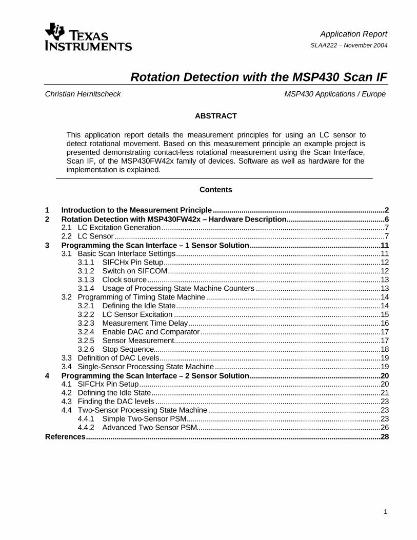
The rotation detection can be realized by placing the inductor of a resonant circuit (LC circuit) near a rotating plate (e.g. the plate on the front of a screw wheel). Half of the plate is covered with a metallic coating such as copper. The damping factor of the stimulated resonant circuitry depends on the position of the inductor relative to the metal. If the inductor is above the metallic half of the plate the damping factor is higher than if located above the non-metallic half of the plate. By detecting the different damping factors the rotation measurement is realized.
Use of one LC circuit sensor allows measurement of rotation without detecting the direction. A second LC sensor makes it possible to also detect the direction of the rotation. Such a system is shown in Figure 1. The inductors are placed in a 90° off-axis angle above the plate and a 180° metallic coating is used. This assures that the damping factor of only one sensor at a time will change when the metallic/non-metallic boundary of the plate rotates across a sensor.
L
L
C
C
Scan Interface:excitation &
measurementcircuitry
Figure 1. Rotation detection using two LC sensors
The sampling rate depends on the maximum rotational frequency that should be detected, and also on the system (number of sensors, angle between sensors, and angle of metallic plate coating). The following formula can be used for calculation of the minimum sampling rate of a system with two sensors and a 180° covered plate:
maxmin *360
*2 rotationratesamplingα
°=
minratesampling : minimum sampling rate α : angle between the two sensors (e.g. 90°) maxrotation : maximum rotational frequency to be detected
SLAA222
Rotation Detection with the MSP430 Scan IF 3
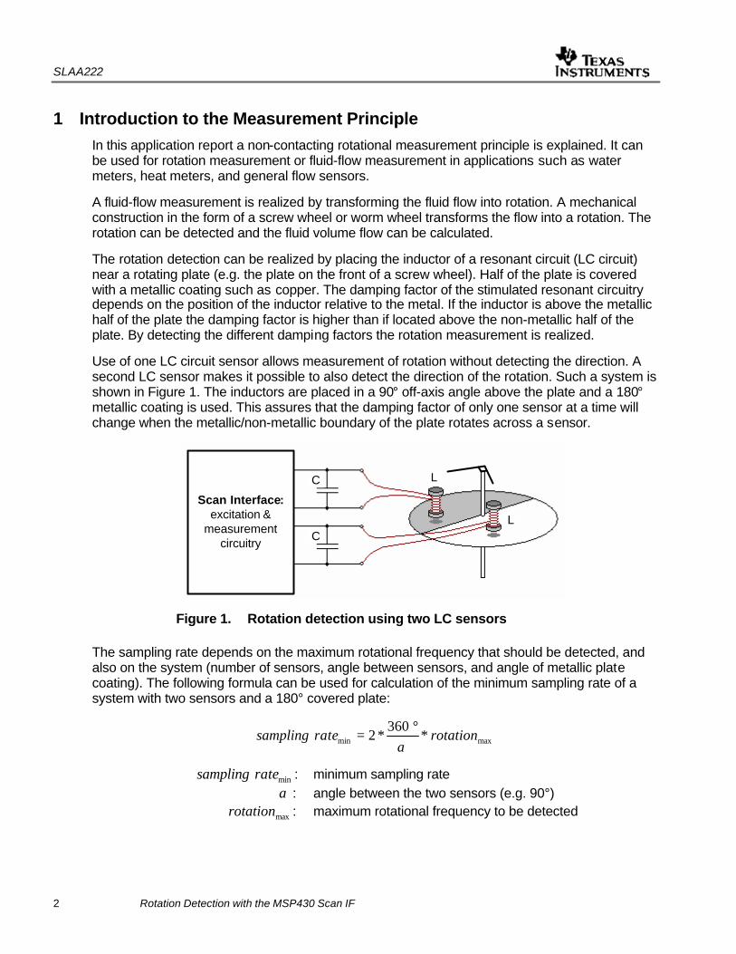
The measurements of both sensors in a two-sensor system are triggered at the sampling rate. Ideally, both measurements would happen at the same time. However in a real application using the MSP430FW42x microcontroller, the measurements of the two sensors are done one after another. The time between the two measurements should be as short as possible. The measurement starts with the stimulation of the resonant circuitry (LC sensor). After releasing the
sensor a damped oscillation with a frequency near CL×
× 121π
is generated. The damped
oscillation is created by the location of the damping plate relative to the sensor. Figure 2 shows this behavior.
Sensor 1
Sensor 2
Sensor 1
Sensor 2
Sensor 1
Sensor 2
Sensor 1
Sensor 2
State a
State b
State c
State d
Damped
Undamped
Figure 2. Example LC sensor output during rotation

SLAA222
4 Rotation Detection with the MSP430 Scan IF
Before the microcontroller can process the sensor signals (damped oscillations) they must be converted into digital signals. The MSP430FW42x Scan IF module provides two ways to perform this conversion.
Ø Envelop Test: The positive or negative alternation of the damped oscillation is used to charge a capacitor. The capacitor voltage builds the envelope curve of the damped oscillation. By measuring the discharge time of the capacitor voltage the damping factor of the oscillation can be measured. The application report “An Electronic Water Meter Design Using MSP430F41x” describes such a solution.
Ø Oscillation Test: The amplitude of the damped oscillation is directly observed. After the excitation a defined delay time, tdelay, allows the LC oscillation to decay. After the delay time a comparator is used to test whether the remaining amplitude is above or below a user-define reference voltage. If the amplitude reaches the defined level during the time tgate a latch is set (see the output stage description in the Scan Interface chapter of the MSP430x4xx User’s Guide). If the amplitude does not reach the defined reference VREF during the time tgate the latch stays in the reset state. This operation is shown in Figure 3. The hardware (reference voltage, comparator) for this test is detailed in the Scan Interface module description as well. The reference voltage generation is realized by a built-in digital-to-analog converter, DAC.
tdelay tdelaytgate tgate
VREF
Inductor above non-metallic surfaceBinary equivalent = "1"
Inductor above metallic surfaceBinary equivalent = "0"
VMID
Figure 3. LC sensor signal damping and Scan IF detection
The oscillation test method is used in the implementation presented in this application report.
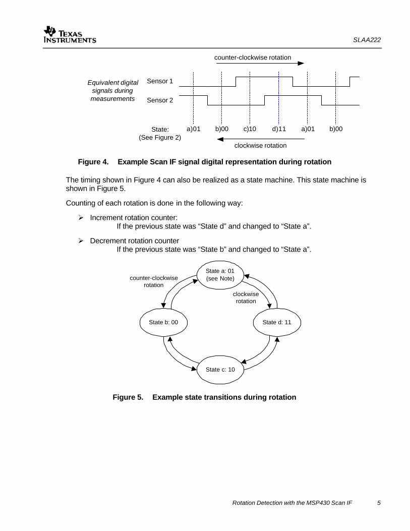
Finally the digitized damping factor is processed. Figure 4 shows the digitized signal for a rotating plate using two LC sensors. Depending on the direction of the rotation either the digital level of sensor 1 or the digital level of sensor 2 changes. If the old state and the new state are known it is possible to also detect the direction of rotation.
SLAA222
Rotation Detection with the MSP430 Scan IF 5
Equivalent digitalsignals duringmeasurements
Sensor 1
Sensor 2
State:(See Figure 2)
a)01 b)00 c)10 d)11 a)01 b)00
counter-clockwise rotation
clockwise rotation
Figure 4. Example Scan IF signal digital representation during rotation
The timing shown in Figure 4 can also be realized as a state machine. This state machine is shown in Figure 5.
Counting of each rotation is done in the following way:
Ø Increment rotation counter: If the previous state was “State d” and changed to “State a”.
Ø Decrement rotation counter If the previous state was “State b” and changed to “State a”.
State a: 01(see Note)
State b: 00
State c: 10
State d: 11
clockwiserotation
counter-clockwiserotation
Figure 5. Example state transitions during rotation

SLAA222
6 Rotation Detection with the MSP430 Scan IF
2 Rotation Detection with MSP430FW42x – Hardware Description The MSP430FW42x’s Scan Interface module can handle the complete measurement sequence which is described in Chapter 1. Only the LC sensor(s), a bypass capacitor for the VMID voltage generation and a 32.768 kHz reference clock (crystal) needs to be connected to the MSP430 to establish proper Scan IF module operation.
Figure 6 shows the schematic of an example rotation detection implementation. Two LC sensors are connected to the Scan IF interface. On the LCD display the number of rotations or the calculated fluid volume flow can be shown.
VI-302-DP
MSP430FW427
AVCC
AVSS
DVCC
DVSS
VCC
100nF3.0 V
VCC
68k
100nFRST
XIN
XOUT
32.768 kHz
COM0S0
S23:
SIFCOM
SIFVSS
SIFCH0
R03
470nF
1nF 100uH 100uH1nF
SIFCH1Sensor 1 Sensor 2
VMID
Figure 6. Example application schematic
The MSP430FW42x implementation shown in Figure 6 was used to test the software explained in the following chapters. This design along with a rotating 180° copper-coated plate makes up the entire test setup.
SLAA222
Rotation Detection with the MSP430 Scan IF 7
2.1 LC Excitation Generation
The LC excitation pulse generating the required oscillation is output on the given SIFCHx pin. The oscillation occurs around VMID and is generated on the SIFCOM output. For the SIFCOM voltage generation an external capacitor connected between SIFCOM and SIFVSS is required. The VMID generator built into the Scan IF analog front-end generates a VCC/2 or VMID voltage. The VMID generator provides that the voltage swing of the LC sensor is not clipped by the two integrated protection diodes (ESD protection) at the pins SIFCH0 and SIFCH1 to AVSS or AVCC. The damped oscillation swings around VCC/2 and the maximum amplitude is limited to AVCC + VDIODE. The VMID generator dissipates low current and the dynamic impedance is ensured due to the external 470nF capacitor. The refresh period is derived from ACLK and VCC/2 can only be generated if the ACLK signal – typically 32.768 kHz – is switched on.
2.2 LC Sensor
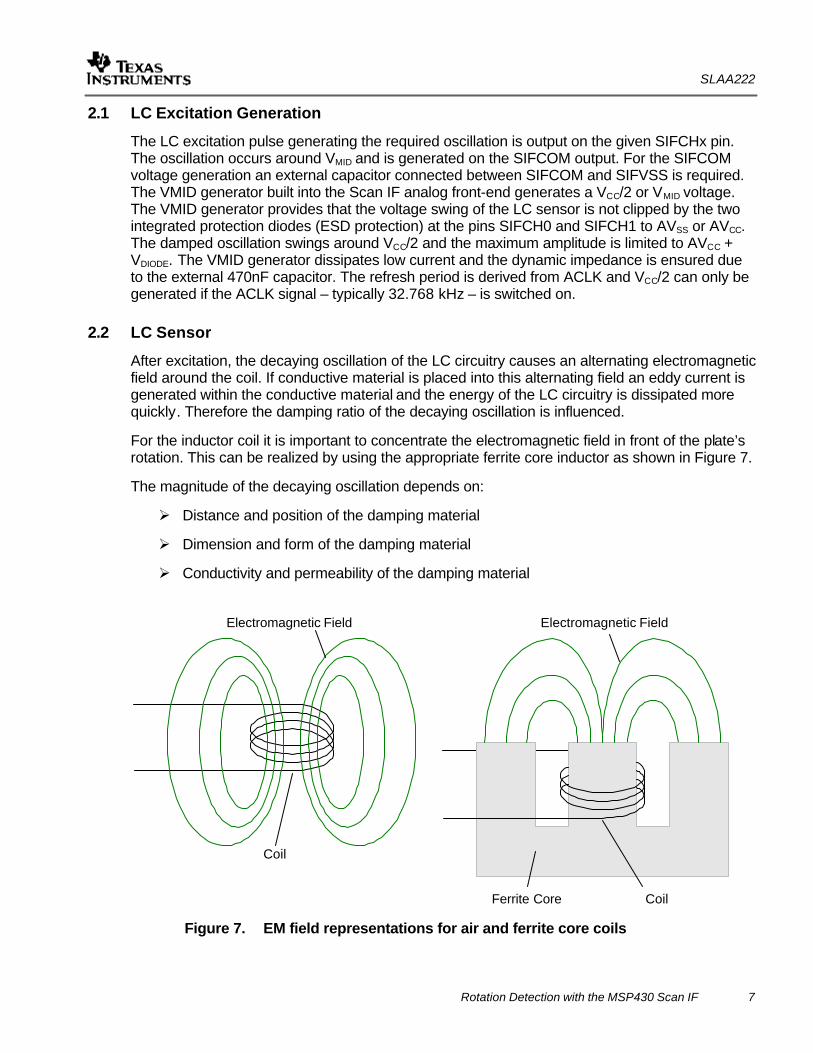
After excitation, the decaying oscillation of the LC circuitry causes an alternating electromagnetic field around the coil. If conductive material is placed into this alternating field an eddy current is generated within the conductive material and the energy of the LC circuitry is dissipated more quickly. Therefore the damping ratio of the decaying oscillation is influenced.
For the inductor coil it is important to concentrate the electromagnetic field in front of the plate’s rotation. This can be realized by using the appropriate ferrite core inductor as shown in Figure 7.
The magnitude of the decaying oscillation depends on:
Ø Distance and position of the damping material
Ø Dimension and form of the damping material
Ø Conductivity and permeability of the damping material
Coil
Electromagnetic Field
Ferrite Core
Coil
Electromagnetic Field
Figure 7. EM field representations for air and ferrite core coils
SLAA222
8 Rotation Detection with the MSP430 Scan IF
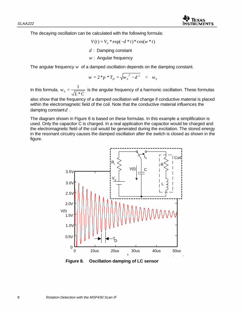
The decaying oscillation can be calculated with the following formula:
)*cos(*)*exp(*)( 0 ttVtV ωδ−=
δ : Damping constant
ω : Angular frequency
The angular frequency ω of a damped oscillation depends on the damping constant.
022
0**2 ωδωπω <−== DT
In this formula, CL *
10 =ω is the angular frequency of a harmonic oscillation. These formulas
also show that the frequency of a damped oscillation will change if conductive material is placed within the electromagnetic field of the coil. Note that the conductive material influences the damping constantδ .
The diagram shown in Figure 8 is based on these formulas. In this example a simplification is used. Only the capacitor C is charged. In a real application the capacitor would be charged and the electromagnetic field of the coil would be generated during the excitation. The stored energy in the resonant circuitry causes the damped oscillation after the switch is closed as shown in the figure.
0 1 .105
2 .105
3 .105
4 .105
5 .105
0
0.5
1
1.5
2
2.5
3
3.53.1
0
V t( )
5 105−
×0 t
TD
10us 20us 30ust
0 40us 50us
V(t)
0
0.5V
1.0V
1.5V
2.0V
2.5V
3.0V
3.5V
Vo/2
Coil
CR
L
RI
V0
t0
V(t)
Figure 8. Oscillation damping of LC sensor

SLAA222
Rotation Detection with the MSP430 Scan IF 9
An oscillation can be seen when 0ωδ < . Therefore:
L
R*2
=δ , CL *
10 =ω
CL
R *2<⇒
For the calculation of the resonance circuit, the frequency variation caused by the damping constant can be neglected. So for the dimensioning of the LC sensor the capacitance is calculated as follows:
CL
f r *1
**21π
= 22 **4*
1fL
Cπ
≈⇒
f : Frequency of the decaying oscillation
L : Inductance of the used coil
In Table 1, measurements using different capacitances and inductances are listed. Note that here only the resonant frequency was measured. For dimensioning of the LC sensor, the decay time and the current consumption due to the excitation pulse must be taken into consideration.
Table 1. LC combination resonant frequencies
Capacitance C
100 pF 270 pF 470 pF 1 nF
47 uH 2.08 MHz 1.37 MHz 1.06 MHz 725 kHz
100 uH 1.45 MHz 933 kHz 725 kHz 500 kHz
220 uH 980 kHz 641 kHz 490 kHz 338 kHz Inductance L
470 uH 658 kHz 435 kHz 333 kHz 233 kHz
For the selection of the frequency it is important to know that a delay time is necessary before the measurement is made. The ACLK signal is used for the delay time generation. The programming of the timing state machine of the Scan IF should correspond to the selected LC sensor dimensioning. In the example described in the following sections a delay time of around 30 µs (~ 1 ACLK cycle) is used.
The dimensioning of the LC sensor will also affect the current consumption. The excitation pulse length required for proper excitation depends on the selected LC circuitry. The longer the excitation pulse required, the higher the current consumption.
SLAA222
10 Rotation Detection with the MSP430 Scan IF
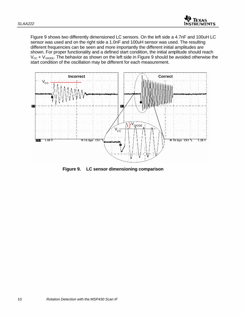
Figure 9 shows two differently dimensioned LC sensors. On the left side a 4.7nF and 100uH LC sensor was used and on the right side a 1.0nF and 100uH sensor was used. The resulting different frequencies can be seen and more importantly the different initial amplitudes are shown. For proper functionality and a defined start condition, the initial amplitude should reach VCC + VDIODE. The behavior as shown on the left side in Figure 9 should be avoided otherwise the start condition of the oscillation may be different for each measurement.
VDIODEVCC
Incorrect CorrectVCC
Figure 9. LC sensor dimensioning comparison

SLAA222
Rotation Detection with the MSP430 Scan IF 11
3 Programming the Scan Interface – 1 Sensor Solution The Scan Interface was designed to process information from up to four sensors using the Processing State Machine, PSM. It is also possible to perform rotation detection with as few as one sensor. In the following example one sensor is assumed and only the rotation, not the direction of the rotation, is detected.
During the software development of the Scan Interface the software developer should consider the following:
Ø Basic Scan Interface Settings
Ø Programming of the Timing State Machine, TSM
Ø Definition of DAC Levels (e.g. VREF)
Ø Programming the Processing State Machine, PSM
For a real-world application it is also important to think about temperature drift, voltage drift, and aging of components.
3.1 Basic Scan Interface Settings
Basic settings are configured with the control registers SIFCTL1 through SIFCTL5. An overview of these registers and the functionality is listed in Table 2.
Table 2. Scan Interface Control Register Settings
Control Register Functionality Description SIFCTL1 Ø Interrupt enable bits and interrupt flags
Ø Test cycle request bit Ø Scan interface enable bit
SIFCTL2 Ø DAC enable bit Ø Comparator enable bit and comparator settings Ø Input selection Ø Sample-and-Hold enable bit (not needed for LC sensors) Ø VMID generator Ø Excitation enable bit Ø Test channel settings
SIFCTL3 Ø Processing State Machine Input selection Ø Interrupt source settings Ø Timer_A comparator signal selection
SIFCTL4 Ø Processing State Machine settings Ø Sample rate definition
SIFCTL5 Ø Timing State Machine settings
SLAA222
12 Rotation Detection with the MSP430 Scan IF
3.1.1 SIFCHx Pin Setup
During the initialization of the Scan Interface module it is necessary to configure the required pins for module functionality (e.g. P6SEL=0x01). Otherwise the digital input influences the measurement. In addition, the damping of other Scan IF inputs when multiple LC sensors are used will not function correctly if the module function is not selected. For additional information, see section 4.1 – “SIFCHx Pin Setup”.
3.1.2 Switch on SIFCOM
The SIFCOM voltage is switched on in the control register SIFCTL2 with the bit SIFVCC2. Note that the ACLK signal is needed to refresh the SIFCOM voltage. If the ACLK signal is switched off the SIFCOM VCC/2 output breaks down.
The VMID generator takes some time to switch on the SIFCOM voltage. The maximum time is given in the MSP430FW42x data sheet. The measurement sequence should only be started if the SIFCOM voltage has settled.
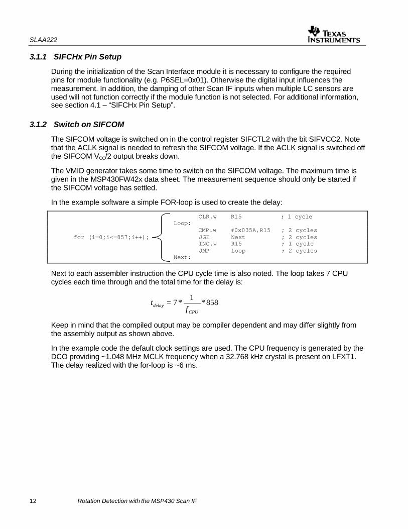
In the example software a simple FOR-loop is used to create the delay:
CLR.w R15 ; 1 cycle Loop: CMP.w #0x035A,R15 ; 2 cycles for (i=0;i<=857;i++); JGE Next ; 2 cycles INC.w R15 ; 1 cycle JMP Loop ; 2 cycles Next:
Next to each assembler instruction the CPU cycle time is also noted. The loop takes 7 CPU cycles each time through and the total time for the delay is:
858*1
*7CPU
delay ft =
Keep in mind that the compiled output may be compiler dependent and may differ slightly from the assembly output as shown above.
In the example code the default clock settings are used. The CPU frequency is generated by the DCO providing ~1.048 MHz MCLK frequency when a 32.768 kHz crystal is present on LFXT1. The delay realized with the for-loop is ~6 ms.

SLAA222
Rotation Detection with the MSP430 Scan IF 13
Figure 10 shows the time delay between switching on the SIFCOM voltage and the first measurement on SIFCH0 with the settling time of ~6ms. The additional delay shown is due to the synchronization of the TSM start trigger to ACLK.
SIFCH0
SIFCOMtdelay
1st measurment
Figure 10. SIFCOM Settling Time
3.1.3 Clock Source
The 32.768 kHz watch crystal generating ACLK must be available in order for the Scan IF to operate correctly. The ACLK signal is used for definition of the sampling rate as well as the time delay generation explained in detail in the following chapters.
The Scan Interface module also contains a dedicated RC-oscillator, SIFOSC. This oscillator generates a 1MHz or 4MHz clock signal. The output frequency can be calibrated if voltage or temperature drift causes a deviation. In order to simplify the calibration measurement process a counter is also integrated into SIFOSC.
3.1.4 Usage of Processing State Machine Counters
There are two 8-bit counters available in the Processing State Machine and are triggered by the PSM on system state transitions. One counter is used as an up/down-counter and the other as a down-counter. During processing the up/down-counter can be used to filter the effects of bouncing as shown in Chapter 4.
SLAA222
14 Rotation Detection with the MSP430 Scan IF
3.2 Programming of the Timing State Machine
The Scan IF’s Timing State Machine, TSM, controls the timing of specific tasks of the module which defines the sequence of measurements of the external channels. Using the TSM it is possible to accurately adjust the time that is needed for each process step independently. In general, the sequence follows the transitions detailed below.
1. Define Idle State (using control register SIFTSM0)
2. Generate LC sensor excitation
3. Delay for ideal sensor measurement window
4. Enable DAC and Comparator, wait for tsettle
5. Initiate sensor measurement
6. Stop Scan IF
These single steps are described in detail in sections 3.2.1 – 3.2.6.
Each TSM state for the actions listed above is shown in the following program code lines which are also used in the example software, which define the TSM operation. ... SIFTSM0 = 0x0000; // DAC=off, Comparator=off, 1xSIFCLK, Idle state SIFTSM1 = 0x002C; // DAC=off, Comparator=off, 1xSIFCLK, Excitation of sensor SIFTSM2 = 0x0404; // DAC=off, Comparator=off, 1xACLK , Measurement delay SIFTSM3 = 0x0934; // DAC=on, Comparator=on, 2xSIFCLK, Analog enable SIFTSM4 = 0x3174; // DAC=on, Comparator=on, 7xSIFCLK, Measurement SIFTSM5 = 0x0220; // stop sequence , Stop state ...
3.2.1 Defining the Idle State
The Idle state is the initial condition of the TSM. In addition, as soon as the measurement sequence is finished by executing the SIFTSM5 state in the above example, the Scan Interface will be switched into the idle state. For the idle state the TSM bit settings in the SIFTSM0 control register are used.
... SIFTSM0 = 0x0000; // DAC=off, Comparator=off, 1xSIFCLK, Idle state ...
If bit 2 (SIFLCEN bit) within the SIFTSM0 control register is reset, all SIFCHx channels are shorted to ground and no oscillation will occur. As soon as the stop state (SIFTSM5) is executed, the idle state will be entered and the SIFTSM0 settings will be applied causing the SIFCHx channels to be tied to ground through SIFCOM. Any present oscillation on the channel will immediately stop.
SLAA222
Rotation Detection with the MSP430 Scan IF 15
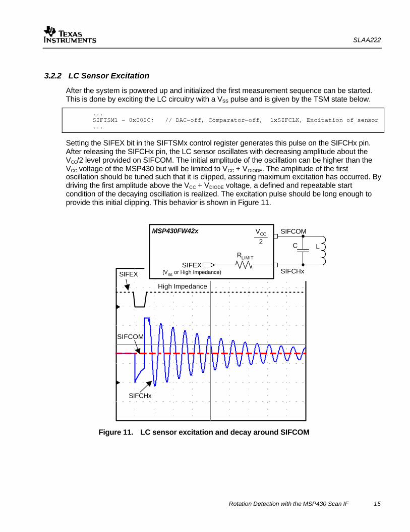
3.2.2 LC Sensor Excitation
After the system is powered up and initialized the first measurement sequence can be started. This is done by exciting the LC circuitry with a VSS pulse and is given by the TSM state below.
... SIFTSM1 = 0x002C; // DAC=off, Comparator=off, 1xSIFCLK, Excitation of sensor ...
Setting the SIFEX bit in the SIFTSMx control register generates this pulse on the SIFCHx pin. After releasing the SIFCHx pin, the LC sensor oscillates with decreasing amplitude about the VCC/2 level provided on SIFCOM. The initial amplitude of the oscillation can be higher than the VCC voltage of the MSP430 but will be limited to VCC + VDIODE. The amplitude of the first oscillation should be tuned such that it is clipped, assuring maximum excitation has occurred. By driving the first amplitude above the VCC + VDIODE voltage, a defined and repeatable start condition of the decaying oscillation is realized. The excitation pulse should be long enough to provide this initial clipping. This behavior is shown in Figure 11.
SIFCHx
High Impedance
SIFCOM
SIFEXSIFEX
(VSS or High Impedance)
VCC
RLIMIT
LC
MSP430FW42x
SIFCHx
SIFCOM2
Figure 11. LC sensor excitation and decay around SIFCOM
SLAA222
16 Rotation Detection with the MSP430 Scan IF
3.2.3 Measurement Time Delay
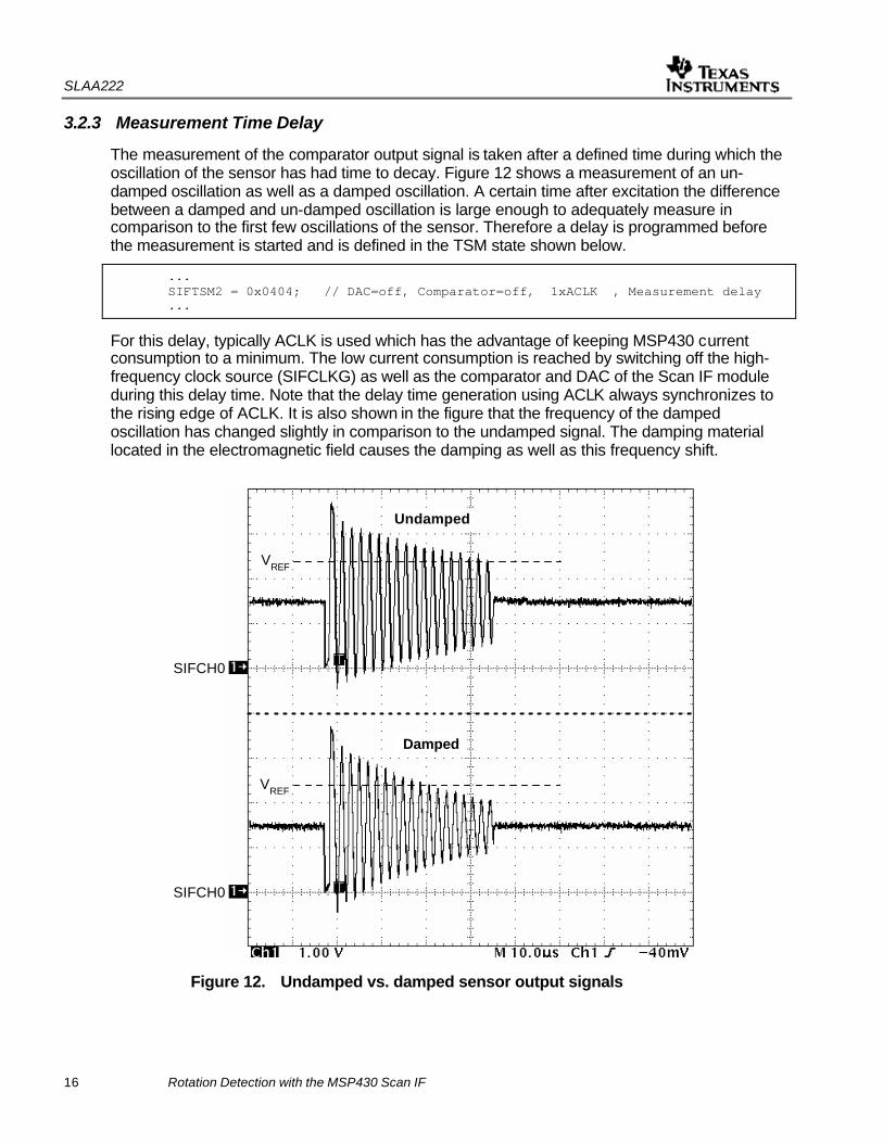
The measurement of the comparator output signal is taken after a defined time during which the oscillation of the sensor has had time to decay. Figure 12 shows a measurement of an un-damped oscillation as well as a damped oscillation. A certain time after excitation the difference between a damped and un-damped oscillation is large enough to adequately measure in comparison to the first few oscillations of the sensor. Therefore a delay is programmed before the measurement is started and is defined in the TSM state shown below.
... SIFTSM2 = 0x0404; // DAC=off, Comparator=off, 1xACLK , Measurement delay
...
For this delay, typically ACLK is used which has the advantage of keeping MSP430 current consumption to a minimum. The low current consumption is reached by switching off the high-frequency clock source (SIFCLKG) as well as the comparator and DAC of the Scan IF module during this delay time. Note that the delay time generation using ACLK always synchronizes to the rising edge of ACLK. It is also shown in the figure that the frequency of the damped oscillation has changed slightly in comparison to the undamped signal. The damping material located in the electromagnetic field causes the damping as well as this frequency shift.
Undamped
Damped
SIFCH0
SIFCH0
VREF
VREF
Figure 12. Undamped vs. damped sensor output signals

SLAA222
Rotation Detection with the MSP430 Scan IF 17
3.2.4 Enable DAC and Comparator
Before the measurement can be made the DAC and comparator must be switched on. This can be achieved in two different ways. One method is to permanently enable the DAC and comparator for all TSM states. The bits in the control register SIFCTL2 are used to enable these elements. In this case the SIFTSMx DAC enable and comparator enable bits are inactive.
However, if the respective bits SIFCTL2 are reset, the DAC and comparator can be activated only when a measurement is made. This is done with the bits located in the SIFTSMx control register and given in the state entry below.
... SIFTSM3 = 0x0934; // DAC=on, Comparator=on, 2xSIFCLK, Analog enable ...
The activation of the DAC and comparator only for the short time during each measurement will reduce the current consumption of the system. In addition, it is important to wait until the DAC and comparator have settled after being enabled since these are precision analog components. The settling time for each is defined in the device-specific data sheet.
3.2.5 Sensor Measurement
Actual measurement of the LC sensor is made during TSM state 4.
... SIFTSM4 = 0x3174; // DAC=on, Comparator=on, 7xSIFCLK, Measurement ...
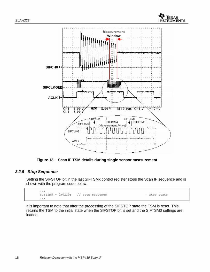
The TSM states discussed in the prior sections are also shown in Figure 13. It is important to note that between 3 and 4 sensor oscillation periods are sampled during the measurement. It is critical that multiple oscillations are used for the measurement since the damping of the coil will also influence the resonant frequency potentially causing a single oscillation to shift outside of the measurement window.
Figure 13 also shows the rising edge synchronization of ACLK. The measurement sequence starts at SIFTSM0 with the rising edge of ACLK. Initially, SIFCLK has been switched on and then the excitation pulse is generated which takes a few SIFCLK cycles. After excitation, the delay of one ACLK (to the next rising edge of ACLK) is generated.
The single clock cycles of the sequence for SIFTSM2, SIFTSM3, SIFTSM4, and SIFTSM5 are shown in detail as well.
SLAA222
18 Rotation Detection with the MSP430 Scan IF
MeasurementWindow
SIFCH0
SIFCLKG
ACLK
SIFTSM2
SIFTSM3SIFTSM4
(Measurement Active)
SIFTSM5SIFTSM0
SIFCLKG
ACLK
Figure 13. Scan IF TSM details during single sensor measurement
3.2.6 Stop Sequence
Setting the SIFSTOP bit in the last SIFTSMx control register stops the Scan IF sequence and is shown with the program code below.
... SIFTSM5 = 0x0220; // stop sequence , Stop state ...
It is important to note that after the processing of the SIFSTOP state the TSM is reset. This returns the TSM to the initial state when the SIFSTOP bit is set and the SIFTSM0 settings are loaded.
SLAA222
Rotation Detection with the MSP430 Scan IF 19
3.3 Definition of DAC Levels
For the single sensor solution, constants are used for the DAC levels. These levels are determined by activating the DAC signal on the pin of the MSP430FW42x. Note that during normal operation the DAC voltage should not be switched out on a pin. This may influence the accuracy of the sensor measurement.
By monitoring the damped oscillation of the sensors and the DAC level, the DAC threshold level can be adjusted. The two cases – damped and undamped oscillation – should be used to determine the DAC level thresholds.
An algorithm that automatically finds the DAC levels is described in section 4.x.
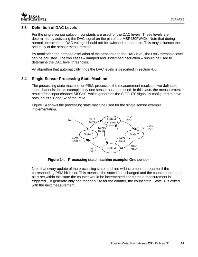
3.4 Single-Sensor Processing State Machine
The processing state machine, or PSM, processes the measurement results of two definable input channels. In this example only one sensor has been used. In this case, the measurement result of the input channel SIFCH0, which generates the SIFOUT0 signal, is configured to drive both inputs S1 and S2 of the PSM.
Figure 14 shows the processing state machine used for the single sensor example implementation.
State 3increment
State 0 State 7
State 4
S1=1S2=1Init
S1=1S2=1
S1=0S2=0
S1=1S2=1
S1=0S2=0
S1=1S2=1
S1=0S2=0
S1=0S2=0
Figure 14. Processing state machine example: One sensor
Note that every update of the processing state machine will increment the counter if the corresponding PSM bit is set. This means if the state is not changed and the counter increment bit is set within this state the counter would be incremented each time a measurement is triggered. To generate only one trigger pulse for the counter, the count state, State 3, is exited with the next measurement.
SLAA222
20 Rotation Detection with the MSP430 Scan IF
4 Programming the Scan Interface – 2 Sensor Solution In addition to the single sensor implementation described earlier, this section presents a two sensor implementation that detects rotation and direction. The two sensor system is based on the Scan IF fundamentals of operation as given in the one sensor solution.
4.1 SIFCHx Pin Setup
In order to properly measure each LC sensor, it is important that each SIFCHx port pin is initialized properly. There is the possibility to short those SIFCHx channels that are not used for the current sensor measurement. This feature was implemented to prevent multiple coils, which are usually located close together, from influencing each other.
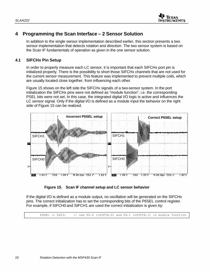
Figure 15 shows on the left side the SIFCHx signals of a two-sensor system. In the port initialization the SIFCHx pins were not defined as “module function”, i.e. the corresponding PSEL bits were not set. In this case, the integrated digital I/O logic is active and influences the LC sensor signal. Only if the digital I/O is defined as a module input the behavior on the right side of Figure 15 can be realized.
Incorrect P6SEL setup Correct P6SEL setup
SIFCH1
SIFCH0
SIFCH1
SIFCH0
Figure 15. Scan IF channel setup and LC sensor behavior
If the digital I/O is defined as a module output, no oscillation will be generated on the SIFCHx pins. The correct initialization has to set the corresponding bits of the P6SEL control register. For example, if SIFCH0 and SIFCH1 are used the correct initialization is given by: P6SEL |= 0x03; // use P6.0 (=SIFCH.0) and P6.1 (=SIFCH.1) in module function
SLAA222
Rotation Detection with the MSP430 Scan IF 21
4.2 Defining the Idle State
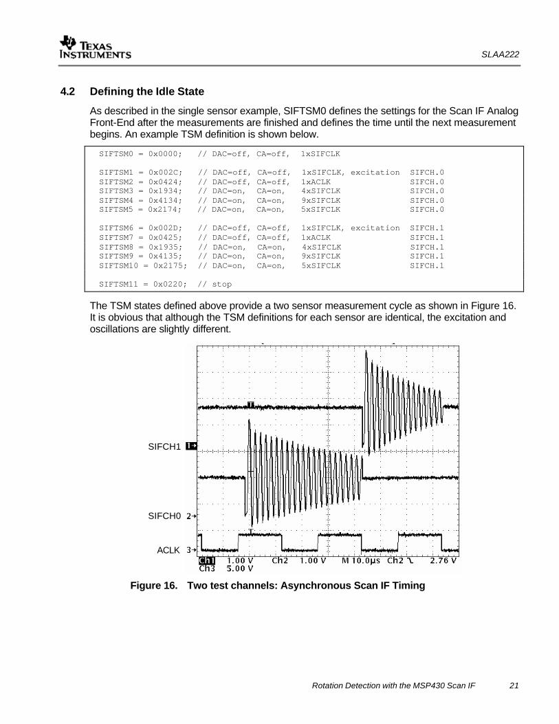
As described in the single sensor example, SIFTSM0 defines the settings for the Scan IF Analog Front-End after the measurements are finished and defines the time until the next measurement begins. An example TSM definition is shown below.
SIFTSM0 = 0x0000; // DAC=off, CA=off, 1xSIFCLK SIFTSM1 = 0x002C; // DAC=off, CA=off, 1xSIFCLK, excitation SIFCH.0 SIFTSM2 = 0x0424; // DAC=off, CA=off, 1xACLK SIFCH.0 SIFTSM3 = 0x1934; // DAC=on, CA=on, 4xSIFCLK SIFCH.0 SIFTSM4 = 0x4134; // DAC=on, CA=on, 9xSIFCLK SIFCH.0 SIFTSM5 = 0x2174; // DAC=on, CA=on, 5xSIFCLK SIFCH.0 SIFTSM6 = 0x002D; // DAC=off, CA=off, 1xSIFCLK, excitation SIFCH.1 SIFTSM7 = 0x0425; // DAC=off, CA=off, 1xACLK SIFCH.1 SIFTSM8 = 0x1935; // DAC=on, CA=on, 4xSIFCLK SIFCH.1 SIFTSM9 = 0x4135; // DAC=on, CA=on, 9xSIFCLK SIFCH.1 SIFTSM10 = 0x2175; // DAC=on, CA=on, 5xSIFCLK SIFCH.1 SIFTSM11 = 0x0220; // stop
The TSM states defined above provide a two sensor measurement cycle as shown in Figure 16. It is obvious that although the TSM definitions for each sensor are identical, the excitation and oscillations are slightly different.
SIFCH1
SIFCH0
ACLK
Figure 16. Two test channels: Asynchronous Scan IF Timing
SLAA222
22 Rotation Detection with the MSP430 Scan IF
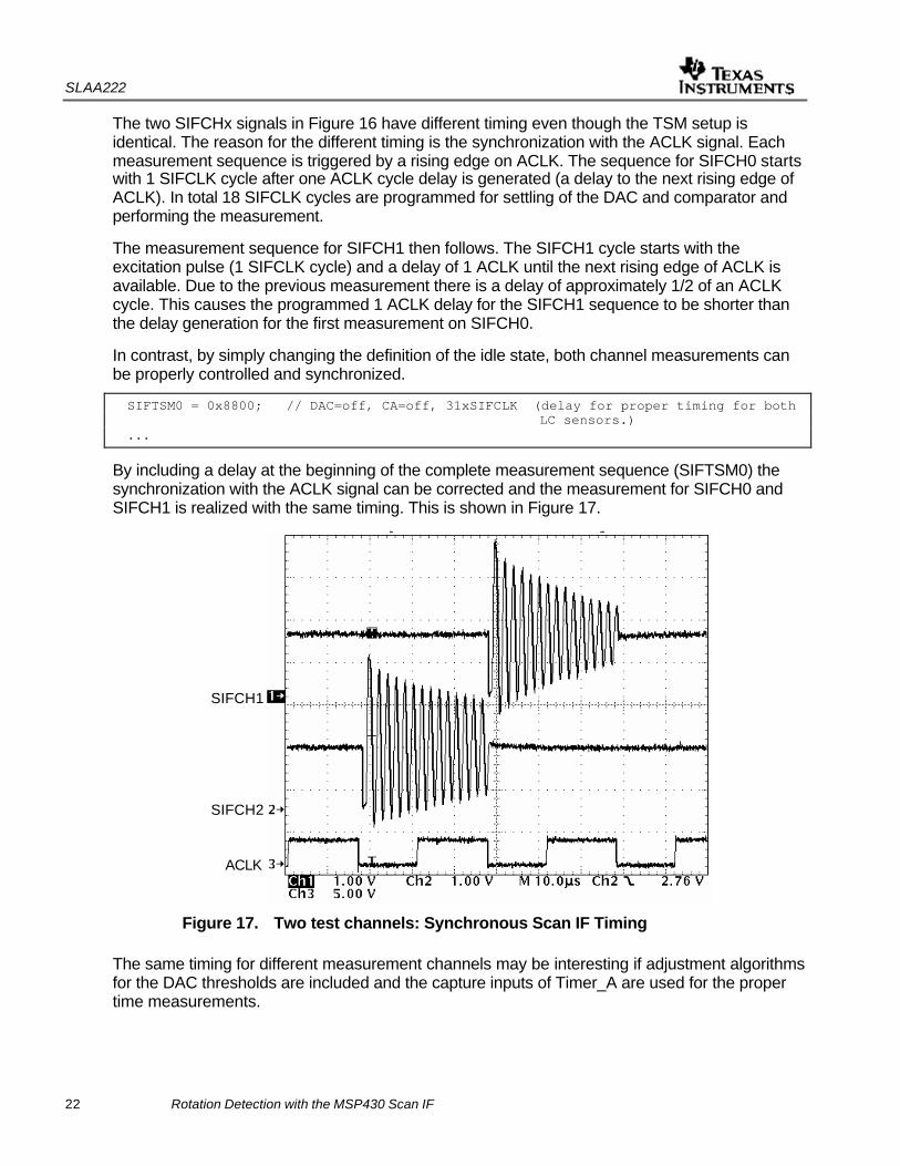
The two SIFCHx signals in Figure 16 have different timing even though the TSM setup is identical. The reason for the different timing is the synchronization with the ACLK signal. Each measurement sequence is triggered by a rising edge on ACLK. The sequence for SIFCH0 starts with 1 SIFCLK cycle after one ACLK cycle delay is generated (a delay to the next rising edge of ACLK). In total 18 SIFCLK cycles are programmed for settling of the DAC and comparator and performing the measurement.
The measurement sequence for SIFCH1 then follows. The SIFCH1 cycle starts with the excitation pulse (1 SIFCLK cycle) and a delay of 1 ACLK until the next rising edge of ACLK is available. Due to the previous measurement there is a delay of approximately 1/2 of an ACLK cycle. This causes the programmed 1 ACLK delay for the SIFCH1 sequence to be shorter than the delay generation for the first measurement on SIFCH0.
In contrast, by simply changing the definition of the idle state, both channel measurements can be properly controlled and synchronized.
SIFTSM0 = 0x8800; // DAC=off, CA=off, 31xSIFCLK (delay for proper timing for both LC sensors.) ...
By including a delay at the beginning of the complete measurement sequence (SIFTSM0) the synchronization with the ACLK signal can be corrected and the measurement for SIFCH0 and SIFCH1 is realized with the same timing. This is shown in Figure 17.
SIFCH1
SIFCH2
ACLK
Figure 17. Two test channels: Synchronous Scan IF Timing
The same timing for different measurement channels may be interesting if adjustment algorithms for the DAC thresholds are included and the capture inputs of Timer_A are used for the proper time measurements.
SLAA222
Rotation Detection with the MSP430 Scan IF 23
4.3 Finding the DAC levels
The two sensor example software uses a simple DAC threshold calibration to determine the VREF levels for each sensor. During the threshold calibration the plated disc must be rotating.
The calibration for each sensor is done in two steps. First the DAC value is set to the maximum, 0x3FF. Then the SIFxOUT bit in the SIFCTL3 control register is checked. As long as SIFxOUT = 0, the DAC value is decremented and the SIFxOUT bit is tested again. When SIFxOUT = 1, the DAC value is stored in the address V0. For the second step, the DAC value is set to mid-scale, 0x0200. This value defines a reference level that should be approximately equal to the VMID voltage and the SIFxOUT bit will be set. Now the DAC value is incremented until SIFxOUT =0. In this case the DAC value is stored in V1.
The average value of V1 and V2 is calculated and represents the threshold point for the damped vs. undamped measurement. A small hysteresis is added to and subtracted from the average value for the two DAC settings per sensor channel, respectively, in order to reject small variations from the measurement. This simple algorithm is used in the example code that is supplied with this report.
4.4 Two Sensor Processing State Machine
This section details two approaches for configuring the PSM in the two sensor example.
4.4.1 Simple Two-Sensor PSM
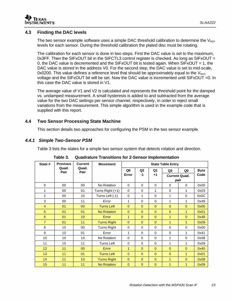
Table 3 lists the states for a simple two sensor system that detects rotation and direction.
Table 3. Quadrature Transitions for 2-Sensor Implementation State Table Entry
Q3 Q0
State # Previous Quad. Pair
Current Quad. Pair
Movement
Q6 Error
Q2 -1
Q1 +1 Current Quad.
pair
Byte Code
0 00 00 No Rotation 0 0 0 0 0 0x00
1 00 01 Turns Right (+1) 0 0 1 0 1 0x03 2 00 10 Turns Left (-1) 0 1 0 1 0 0x0C
3 00 11 Error 1 0 0 1 1 0x49 4 01 00 Turns Left 0 0 0 0 0 0x00
5 01 01 No Rotation 0 0 0 0 1 0x01 6 01 10 Error 1 0 0 1 0 0x48
7 01 11 Turns Right 0 0 0 1 1 0x09 8 10 00 Turns Right 0 0 0 0 0 0x00
9 10 01 Error 1 0 0 0 1 0x41 10 10 10 No Rotation 0 0 0 1 0 0x08
11 10 11 Turns Left 0 0 0 1 1 0x09 12 11 00 Error 1 0 0 0 0 0x40
13 11 01 Turns Left 0 0 0 0 1 0x01
14 11 10 Turns Right 0 0 0 1 0 0x08 15 11 11 No Rotation 0 0 0 1 1 0x09
SLAA222
24 Rotation Detection with the MSP430 Scan IF
In the column “Movement” the expressions have the following meaning:
- No Rotation: Input signals S1 and S2 do not change and the PSM stays in the same state. (e.g. State 5 and input signals S1=1, S2=0)
- Turns Right or Turns Left: The PSM is in a state that will be exited with the next measurement. Depending on the direction of the rotation the S1 and S2 input signals will be different allowing for sensing the direction of the rotation.
- Error: An erroneous state transition has occurred. A properly functioning system will not make such a transition.
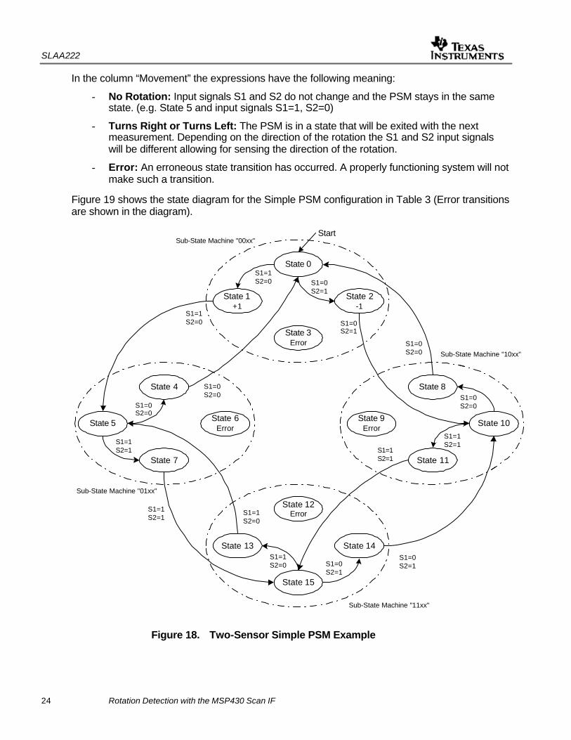
Figure 19 shows the state diagram for the Simple PSM configuration in Table 3 (Error transitions are shown in the diagram).
State 6Error
State 0
State 1+1
State 2-1
State 3Error
State 4
State 5
State 7
State 8
State 9Error
State 10
State 11
State 12Error
State 13 State 14
State 15
S1=1S2=0
S1=1S2=0
S1=1S2=1
S1=1S2=1
S1=0S2=1
S1=0S2=1
S1=0S2=0
S1=0S2=0
S1=0S2=0
S1=0S2=1
S1=0S2=1
S1=1S2=1
S1=1S2=1
S1=1S2=0
S1=1S2=0
S1=0S2=0
Sub-State Machine "11xx"
Sub-State Machine "00xx"
Sub-State Machine "01xx"
Sub-State Machine "10xx"
Start
Figure 18. Two-Sensor Simple PSM Example
SLAA222
Rotation Detection with the MSP430 Scan IF 25
Four sub-state machines are used to realize the PSM in Figure 18. In contrast to the single sensor implementation, the two-sensor PSM includes the detection of the rotational direction in addition to simple rotation. This version only increments or decrements the PSM counter if a complete rotation is completed.
A shortfall of this PSM version is the ability to handle potential bouncing of the disc. If a coil is just between the non-metallic and metallic areas of the bouncing disc one of the PSM input signals may toggle. For example, this could be a problem if the PSM points to state 0 and disc bounce occurs. Assume the input signal S1 toggles. When S1 is set, the PSM will change to state 1 and increment the counter.
For the next measurement S1=1 is again measured. Now the PSM points to state 5. Assume now S1=0 due to the bounce of the disc. The PSM points to state 4 and with the next measurement to state 0. Note that no rotation has been completed. Only bouncing of the disc and sensor S1 has occurred. If this bouncing continues, the PSM counter will be incremented again without a complete rotation.
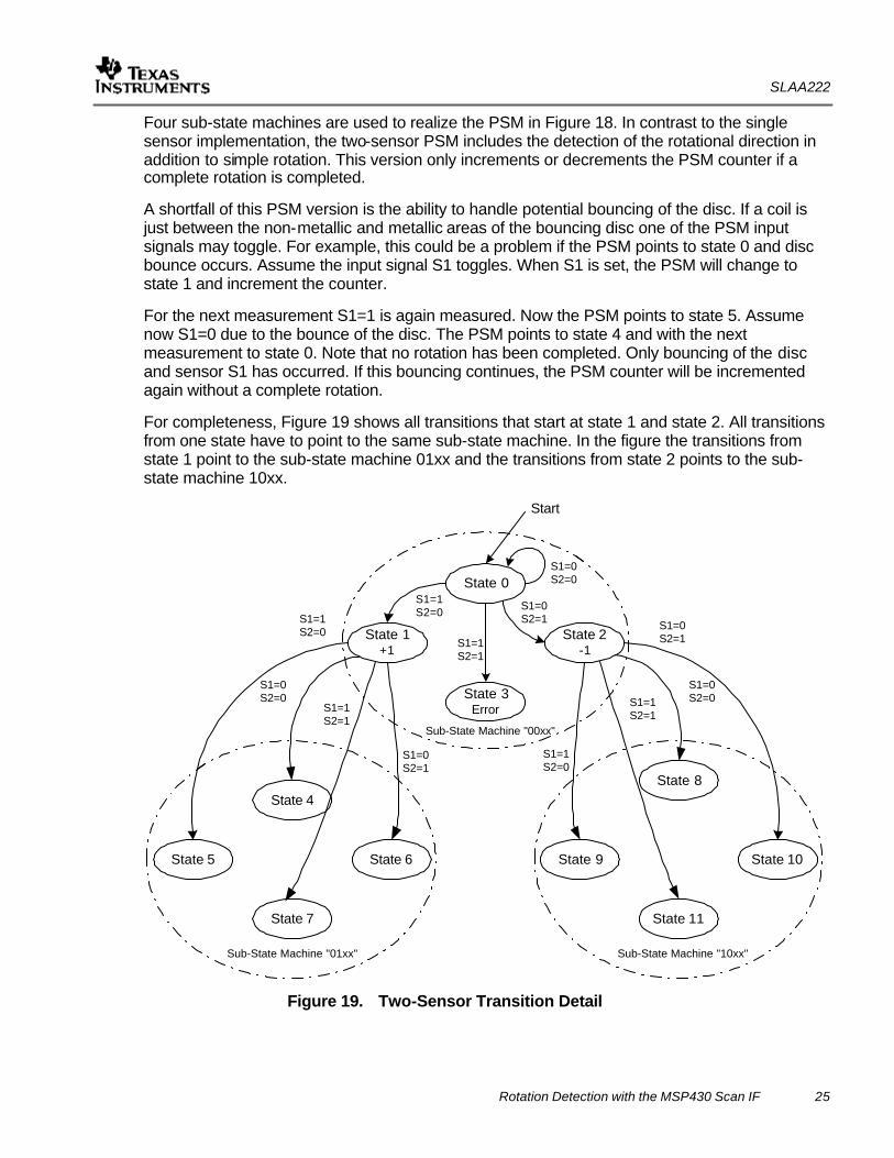
For completeness, Figure 19 shows all transitions that start at state 1 and state 2. All transitions from one state have to point to the same sub-state machine. In the figure the transitions from state 1 point to the sub-state machine 01xx and the transitions from state 2 points to the sub-state machine 10xx.
State 0
State 1+1
State 2-1
State 3Error
S1=1S2=0S1=1
S2=0
S1=0S2=1 S1=0
S2=1
Sub-State Machine "00xx"
Sub-State Machine "01xx" Sub-State Machine "10xx"
Start
S1=0S2=0
S1=1S2=1
State 4
State 5 State 6
State 7
State 8
State 9 State 10
State 11
S1=0S2=0
S1=1S2=1
S1=0S2=1
S1=0S2=0S1=1
S2=1
S1=1S2=0
Figure 19. Two-Sensor Transition Detail
SLAA222
26 Rotation Detection with the MSP430 Scan IF
4.4.2 Advanced Two-Sensor PSM
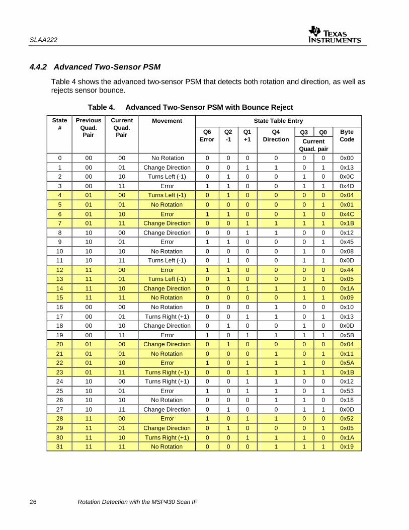
Table 4 shows the advanced two-sensor PSM that detects both rotation and direction, as well as rejects sensor bounce.
Table 4. Advanced Two-Sensor PSM with Bounce Reject
State Table Entry
Q3 Q0
State #
Previous Quad. Pair
Current Quad. Pair
Movement
Q6 Error
Q2 -1
Q1 +1
Q4 Direction Current
Quad. pair
Byte Code
0 00 00 No Rotation 0 0 0 0 0 0 0x00
1 00 01 Change Direction 0 0 1 1 0 1 0x13 2 00 10 Turns Left (-1) 0 1 0 0 1 0 0x0C
3 00 11 Error 1 1 0 0 1 1 0x4D 4 01 00 Turns Left (-1) 0 1 0 0 0 0 0x04
5 01 01 No Rotation 0 0 0 0 0 1 0x01
6 01 10 Error 1 1 0 0 1 0 0x4C 7 01 11 Change Direction 0 0 1 1 1 1 0x1B
8 10 00 Change Direction 0 0 1 1 0 0 0x12 9 10 01 Error 1 1 0 0 0 1 0x45
10 10 10 No Rotation 0 0 0 0 1 0 0x08 11 10 11 Turns Left (-1) 0 1 0 0 1 1 0x0D
12 11 00 Error 1 1 0 0 0 0 0x44 13 11 01 Turns Left (-1) 0 1 0 0 0 1 0x05
14 11 10 Change Direction 0 0 1 1 1 0 0x1A 15 11 11 No Rotation 0 0 0 0 1 1 0x09
16 00 00 No Rotation 0 0 0 1 0 0 0x10
17 00 01 Turns Right (+1) 0 0 1 1 0 1 0x13 18 00 10 Change Direction 0 1 0 0 1 0 0x0D
19 00 11 Error 1 0 1 1 1 1 0x5B 20 01 00 Change Direction 0 1 0 0 0 0 0x04
21 01 01 No Rotation 0 0 0 1 0 1 0x11 22 01 10 Error 1 0 1 1 1 0 0x5A
23 01 11 Turns Right (+1) 0 0 1 1 1 1 0x1B 24 10 00 Turns Right (+1) 0 0 1 1 0 0 0x12
25 10 01 Error 1 0 1 1 0 1 0x53 26 10 10 No Rotation 0 0 0 1 1 0 0x18
27 10 11 Change Direction 0 1 0 0 1 1 0x0D 28 11 00 Error 1 0 1 1 0 0 0x52
29 11 01 Change Direction 0 1 0 0 0 1 0x05
30 11 10 Turns Right (+1) 0 0 1 1 1 0 0x1A 31 11 11 No Rotation 0 0 0 1 1 1 0x19
SLAA222
Rotation Detection with the MSP430 Scan IF 27
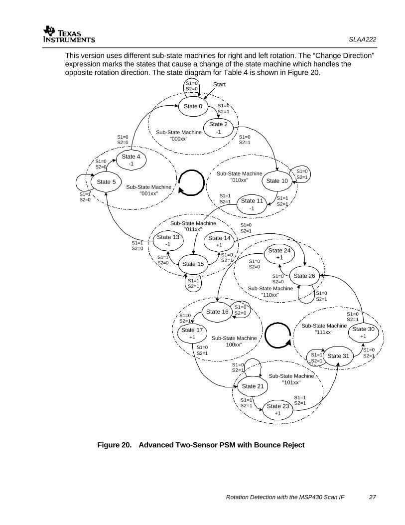
This version uses different sub-state machines for right and left rotation. The “Change Direction” expression marks the states that cause a change of the state machine which handles the opposite rotation direction. The state diagram for Table 4 is shown in Figure 20.
State 0
State 2-1
State 10
State 11-1
State 4-1
State 5
State 13-1
State 15
State 24+1
State 26
State 30+1
State 31
State 16
State 17+1
State 21
State 23+1
Start
Sub-State Machine"010xx"
Sub-State Machine"000xx"
Sub-State Machine"001xx"
S1=0S2=1
S1=0S2=1
S1=1S2=1
S1=0S2=1
S1=1S2=0
S1=1S2=0
S1=0S2=0
S1=0S2=0
S1=1S2=1
S1=0S2=0
S1=1S2=0
S1=1S2=1
State 14+1
S1=0S2=1
S1=0S2=1
S1=0S2=1
S1=0S2=0
Sub-State Machine"110xx"
Sub-State Machine100xx"
Sub-State Machine"101xx"
Sub-State Machine"111xx"
S1=0S2=0
S1=0S2=0S1=0
S2=1
S1=0S2=1
S1=0S2=1
S1=1S2=1
S1=1S2=1
S1=1S2=1
S1=0S2=1
S1=0S2=1
Sub-State Machine"011xx"
Figure 20. Advanced Two-Sensor PSM with Bounce Reject
SLAA222
28 Rotation Detection with the MSP430 Scan IF
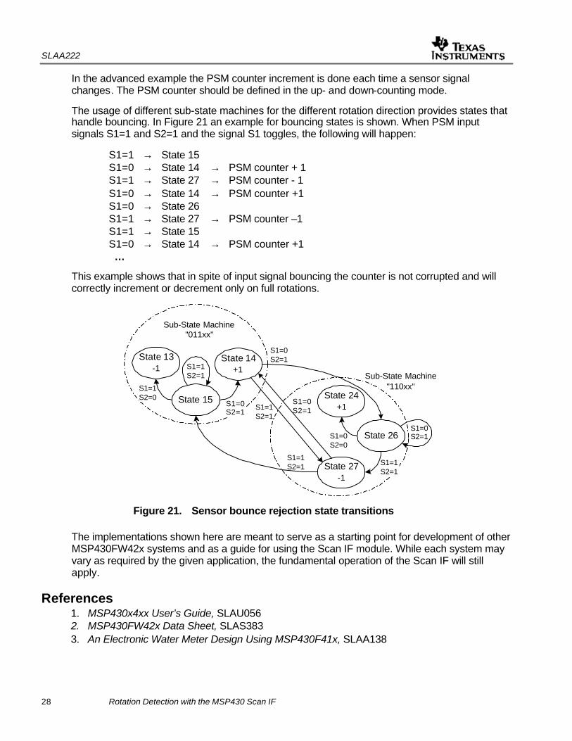
In the advanced example the PSM counter increment is done each time a sensor signal changes. The PSM counter should be defined in the up- and down-counting mode.
The usage of different sub-state machines for the different rotation direction provides states that handle bouncing. In Figure 21 an example for bouncing states is shown. When PSM input signals S1=1 and S2=1 and the signal S1 toggles, the following will happen:
S1=1 → State 15 S1=0 → State 14 → PSM counter + 1 S1=1 → State 27 → PSM counter - 1 S1=0 → State 14 → PSM counter +1 S1=0 → State 26 S1=1 → State 27 → PSM counter –1
S1=1 → State 15 S1=0 → State 14 → PSM counter +1 …
This example shows that in spite of input signal bouncing the counter is not corrupted and will correctly increment or decrement only on full rotations.
State 13-1
State 15 State 24+1
State 26
Sub-State Machine"011xx"
S1=1S2=0
S1=1S2=1
State 14+1
S1=0S2=1
S1=0S2=1S1=0
S2=0
Sub-State Machine"110xx"
State 27-1
S1=1S2=1
S1=1S2=1
S1=0S2=1
S1=0S2=1
S1=1S2=1
Figure 21. Sensor bounce rejection state transitions
The implementations shown here are meant to serve as a starting point for development of other MSP430FW42x systems and as a guide for using the Scan IF module. While each system may vary as required by the given application, the fundamental operation of the Scan IF will still apply.
References 1. MSP430x4xx User’s Guide, SLAU056 2. MSP430FW42x Data Sheet, SLAS383 3. An Electronic Water Meter Design Using MSP430F41x, SLAA138

IMPORTANT NOTICE
Texas Instruments Incorporated and its subsidiaries (TI) reserve the right to make corrections, modifications,enhancements, improvements, and other changes to its products and services at any time and to discontinueany product or service without notice. Customers should obtain the latest relevant information before placingorders and should verify that such information is current and complete. All products are sold subject to TI’s termsand conditions of sale supplied at the time of order acknowledgment.
TI warrants performance of its hardware products to the specifications applicable at the time of sale inaccordance with TI’s standard warranty. Testing and other quality control techniques are used to the extent TIdeems necessary to support this warranty. Except where mandated by government requirements, testing of allparameters of each product is not necessarily performed.
TI assumes no liability for applications assistance or customer product design. Customers are responsible fortheir products and applications using TI components. To minimize the risks associated with customer productsand applications, customers should provide adequate design and operating safeguards.
TI does not warrant or represent that any license, either express or implied, is granted under any TI patent right,copyright, mask work right, or other TI intellectual property right relating to any combination, machine, or processin which TI products or services are used. Information published by TI regarding third-party products or servicesdoes not constitute a license from TI to use such products or services or a warranty or endorsement thereof.Use of such information may require a license from a third party under the patents or other intellectual propertyof the third party, or a license from TI under the patents or other intellectual property of TI.
Reproduction of information in TI data books or data sheets is permissible only if reproduction is withoutalteration and is accompanied by all associated warranties, conditions, limitations, and notices. Reproductionof this information with alteration is an unfair and deceptive business practice. TI is not responsible or liable forsuch altered documentation.
Resale of TI products or services with statements different from or beyond the parameters stated by TI for thatproduct or service voids all express and any implied warranties for the associated TI product or service andis an unfair and deceptive business practice. TI is not responsible or liable for any such statements.
Following are URLs where you can obtain information on other Texas Instruments products and applicationsolutions:
Products Applications
Amplifiers amplifier.ti.com Audio www.ti.com/audio
Data Converters dataconverter.ti.com Automotive www.ti.com/automotive
DSP dsp.ti.com Broadband www.ti.com/broadband
Interface interface.ti.com Digital Control www.ti.com/digitalcontrol
Logic logic.ti.com Military www.ti.com/military
Power Mgmt power.ti.com Optical Networking www.ti.com/opticalnetwork
Microcontrollers microcontroller.ti.com Security www.ti.com/security
Telephony www.ti.com/telephony
Video & Imaging www.ti.com/video
Wireless www.ti.com/wireless
Mailing Address: Texas Instruments
Post Office Box 655303 Dallas, Texas 75265
Copyright 2005, Texas Instruments Incorporated