Embed Size (px)
Citation preview

Actel Corporation, Mountain View, CA 94043
© 2008 Actel Corporation. All rights reserved.
Printed in the United States of America
Part Number: 50200049-10
Release: July 2008
No part of this document may be copied or reproduced in any form or by any means without prior written consent of Actel.
Actel makes no warranties with respect to this documentation and disclaims any implied warranties of merchantability or fitness for a particular purpose. Information in this document is subject to change without notice. Actel assumes no responsibility for any errors that may appear in this document.
This document contains confidential proprietary information that is not to be disclosed to any unauthorized person without prior written consent of Actel Corporation.
Trademarks
Actel and the Actel logotype are registered trademarks of Actel Corporation.
Adobe and Acrobat Reader are registered trademarks of Adobe Systems, Inc.
Mentor Graphics, Precision RTL, Exemplar Spectrum, and LeonardoSpectrum are registered trademarks of Mentor Graphics, Inc.
WaveFormer Lite is a registered trademark of SynaptiCAD, Inc.
Synplify is a registered trademark of Synplicity, Inc.
Sun and Sun Workstation, SunOS, and Solaris are trademarks or registered trademarks of Sun Microsystems, Inc
Synopsys is a registered trademark of Synopsys, Inc.
Verilog is a registered trademark of Open Verilog International.
Viewlogic, ViewSim, ViewDraw and SpeedWave are trademarks or registered trademarks of Viewlogic Systems, Inc.
Windows is a registered trademark and Windows NT is a trademark of Microsoft Corporation in the U.S. and other countries.
UNIX is a registered trademark of X/Open Company Limited.
All other products or brand names mentioned are trademarks or registered trademarks of their respective holders.
SmartTime v8.4 User’s Guide 3
Table of Contents
Welcome to SmartTime ........................................................................................9 About SmartTime....................................................................................................................................9 Design Flows with SmartTime..............................................................................................................10 Starting and Closing SmartTime...........................................................................................................10 SmartTime Components .......................................................................................................................11 SmartTime Constraint Scenario ............................................................................................................12 Setting SmartTime Options ..................................................................................................................13
SmartTime Tutorial ............................................................................................ 15 Start the Tutorial ...................................................................................................................................15 Creating a Clock Constraint..................................................................................................................16 Adding an Input Delay Constraint........................................................................................................18 Adding an Output Delay Constraint .....................................................................................................21 Analyzing the Maximum Operating Frequency ....................................................................................24 Viewing Register-to-Register Paths ......................................................................................................25 Viewing External Setup Paths ...............................................................................................................27 Viewing Clock-to-Output Paths ...........................................................................................................27
SmartTime Constraints Editor ............................................................................ 29 Components of the SmartTime Constraints Editor..............................................................................29 Editable Constraints Grid .....................................................................................................................30 Constraint Wizard .................................................................................................................................31 Using Clock Types.................................................................................................................................38 Understanding Explicit Clocks ..............................................................................................................40 Understanding Potential Clocks ............................................................................................................40 Understanding Clock Networks ............................................................................................................41 Specifying Clock Constraints.................................................................................................................42 Specifying Generated Clock Constraints...............................................................................................44 Using Automatically Generated Clock Constraints ..............................................................................46 Specifying an Input Delay Constraint ...................................................................................................47 Specifying an Output Delay Constraint ................................................................................................51
SmartTime Timing Analyzer............................................................................... 55 Components of the SmartTime Timing Analyzer ................................................................................55 Analyzing Your Design..........................................................................................................................56 Performing a Bottleneck Analysis..........................................................................................................57 Managing Clock Domains.....................................................................................................................59 Managing Path Sets ...............................................................................................................................60
Table of Contents
4 SmartTime v8.4 User’s Guide
Displaying Path List Timing Information.............................................................................................62 Displaying Expanded Path Timing Information...................................................................................64 Using Filters...........................................................................................................................................64 Cross-Probing between ChipPlanner and SmartTime..........................................................................67 Cross-probing Between NetlistViewer and SmartTime........................................................................70
Advanced Timing Analysis .................................................................................. 75 Understanding Inter-Clock Domain Analysis.......................................................................................75 Activating Inter-Clock Domain Analysis ..............................................................................................76 Displaying Inter-Clock Domain Paths..................................................................................................77 Deactivating a Specific Inter-Clock Domain ........................................................................................78 Timing Exceptions Overview ................................................................................................................79 Specifying a Maximum Delay Constraint..............................................................................................80 Specifying a Minimum Delay Constraint..............................................................................................83 Specifying a Multicycle Constraint........................................................................................................86 Specifying a False Path Constraint ........................................................................................................90 Changing Output Port Capacitance ......................................................................................................93 Specifying Clock Source Latency...........................................................................................................94 Specifying Disable Timing Constraint ..................................................................................................95
Generating Timing Reports................................................................................. 97 Types of Reports ....................................................................................................................................97 Generating a Timing Report .................................................................................................................97 Understanding Timing Reports .............................................................................................................98 Generating a Timing Violation Report ...............................................................................................101 Understanding Timing Violation Reports ...........................................................................................101 Generating a Constraints Coverage Report.........................................................................................103 Understanding Constraints Coverage Reports ....................................................................................103 Generating a Bottleneck Report ..........................................................................................................105 Understanding Bottleneck Reports......................................................................................................106 Generating a Datasheet Report ...........................................................................................................107 Understanding Datasheet Reports .......................................................................................................108 Generating a Combinational Loop Report..........................................................................................110 Understanding Combinational Loop Reports .....................................................................................110
Timing Concepts .............................................................................................. 113 Static Timing Analysis Versus Dynamic Simulation...........................................................................113 Delay Models .......................................................................................................................................113 Timing Path Types ..............................................................................................................................113 Maximum Clock Frequency ................................................................................................................114 Setup Check.........................................................................................................................................114 Arrival Time, Required Time, and Slack.............................................................................................114 Timing Exceptions...............................................................................................................................115
Table of Contents
SmartTime v8.4 User’s Guide 5
Clock Skew ..........................................................................................................................................116
Dialog Boxes..................................................................................................... 117 Add Path Analysis Set Dialog Box ......................................................................................................117 Analysis Set Properties Dialog Box .....................................................................................................118 Edit Filter Set Dialog Box ...................................................................................................................120 Select Source Pins for Clock Constraint Dialog Box ..........................................................................121 Create Clock Constraint Dialog Box...................................................................................................122 Create Generated Clock Constraint Dialog Box................................................................................. 123 Customize Analysis View Dialog Box .................................................................................................125 Manage Clock Domain Dialog Box ....................................................................................................126 Select Generated Clock Source Dialog Box ........................................................................................127 Select Generated Clock Reference Dialog Box ...................................................................................128 Select Source or Destination Pins for Constraint Dialog Box............................................................. 129 Set False Path Constraint Dialog Box .................................................................................................132 Set Clock Source Latency Dialog Box.................................................................................................133 Set Constraint to Disable Timing Arcs Dialog Box............................................................................135 Set Input Delay Constraint Dialog Box...............................................................................................137 Set Maximum Delay Constraint Dialog Box.......................................................................................140 Set Minimum Delay Constraint Dialog Box.......................................................................................142 Set Multicycle Constraint Dialog Box.................................................................................................144 Set Output Delay Constraint Dialog Box............................................................................................148 SmartTime Options Dialog Box..........................................................................................................152 Store Filter as Analysis Set Dialog Box ...............................................................................................155 Timing Datasheet Report Options Dialog Box...................................................................................165 Timing Report Options Dialog Box....................................................................................................165 Timing Violations Report Options Dialog Box ..................................................................................170
Menus, Tools, and Shortcut Keys ...................................................................... 173 File Menu.............................................................................................................................................173 Edit Menu............................................................................................................................................173 View Menu ..........................................................................................................................................174 Actions Menu ......................................................................................................................................175 Tools Menu .........................................................................................................................................176 Window Menu.....................................................................................................................................178 Help Menu...........................................................................................................................................178
Data Change History ........................................................................................ 179 Data Change History...........................................................................................................................179 all_inputs..............................................................................................................................................180 all_outputs............................................................................................................................................180 all_registers ..........................................................................................................................................181 check_timing_constraints ....................................................................................................................182
Table of Contents
6 SmartTime v8.4 User’s Guide
clone_scenario ......................................................................................................................................182 create_clock..........................................................................................................................................183 create_generated_clock ........................................................................................................................184 create_scenario .....................................................................................................................................185 delete_scenario .....................................................................................................................................186 get_cells................................................................................................................................................187 get_clocks.............................................................................................................................................187 get_current_scenario ............................................................................................................................188 get_nets ................................................................................................................................................189 get_pins................................................................................................................................................190 get_ports ..............................................................................................................................................190 list_disable_timings..............................................................................................................................191 list_objects............................................................................................................................................191 list_scenarios ........................................................................................................................................192 remove_clock........................................................................................................................................192 remove_clock_latency ..........................................................................................................................193 remove_disable_timing ........................................................................................................................194 remove_false_path................................................................................................................................195 remove_generated_clock ......................................................................................................................196 remove_input_delay .............................................................................................................................197 remove_max_delay ...............................................................................................................................198 remove_min_delay ...............................................................................................................................199 remove_multicycle_path ......................................................................................................................200 remove_output_delay ...........................................................................................................................201 rename_scenario...................................................................................................................................202 set_clock_latency..................................................................................................................................202 set_current_scenario.............................................................................................................................204 set_disable_timing ...............................................................................................................................204 set_false_path (GCF)...........................................................................................................................205 set_input_delay ....................................................................................................................................206 set_max_delay ......................................................................................................................................207 set_min_delay ......................................................................................................................................208 set_multicycle_path..............................................................................................................................210 set_output_delay ..................................................................................................................................211 st_commit ............................................................................................................................................212 st_create_set .........................................................................................................................................213 st_edit_set ............................................................................................................................................215 st_expand_path ....................................................................................................................................215 st_list_paths .........................................................................................................................................218 st_remove_set.......................................................................................................................................220 st_restore ..............................................................................................................................................220 st_set_options.......................................................................................................................................221
Table of Contents
SmartTime v8.4 User’s Guide 7
timer_add_clock_exception..................................................................................................................224 timer_add_pass ....................................................................................................................................225 timer_add_stop ....................................................................................................................................225 timer_commit ......................................................................................................................................226 timer_get_clock_actuals .......................................................................................................................227 timer_get_clock_constraints ................................................................................................................227 timer_get_maxdelay .............................................................................................................................228 timer_get_path.....................................................................................................................................229 timer_get_path_constraints..................................................................................................................231 timer_remove_all_constraints ..............................................................................................................232 timer_remove_clock_exception............................................................................................................233 timer_remove_pass...............................................................................................................................234 timer_remove_stop...............................................................................................................................234 timer_restore ........................................................................................................................................235 timer_set_maxdelay..............................................................................................................................236 timer_setenv_clock_freq ......................................................................................................................237 timer_setenv_clock_period...................................................................................................................237 report (Timing) using SmartTime.......................................................................................................238 report (Timing violations) using SmartTime.......................................................................................241 report (Datasheet) using SmartTime ...................................................................................................243 report (Bottleneck) using SmartTime..................................................................................................244
Constraints by File Format - SDC Command Reference .................................... 247 About Synopsys Design Constraints (SDC) Files ...............................................................................247 SDC Syntax Conventions....................................................................................................................248 create_clock..........................................................................................................................................249 create_generated_clock ........................................................................................................................251 set_clock_latency..................................................................................................................................252 set_disable_timing ...............................................................................................................................254 set_false_path.......................................................................................................................................255 set_input_delay ....................................................................................................................................256 set_load ................................................................................................................................................257 set_max_delay (SDC) ..........................................................................................................................258 set_multicycle_path..............................................................................................................................261 set_output_delay ..................................................................................................................................263
Design Object Access Commands ..................................................................... 265 all_inputs..............................................................................................................................................265 all_registers ..........................................................................................................................................266 all_registers ..........................................................................................................................................267 get cells.................................................................................................................................................268 get_clocks.............................................................................................................................................269
Table of Contents
8 SmartTime v8.4 User’s Guide
get_pins................................................................................................................................................270 get_nets ................................................................................................................................................271 get_ports ..............................................................................................................................................272
Glossary............................................................................................................ 273
Product Support................................................................................................ 277 Customer Service .................................................................................................................................277 Actel Customer Technical Support Center .........................................................................................277 Actel Technical Support ......................................................................................................................277 Website ................................................................................................................................................277 Contacting the Customer Technical Support Center..........................................................................277
SmartTime v8.4 User’s Guide 9
Welcome to SmartTime
About SmartTime SmartTime is a gate-level static timing analysis tool for the IGLOO, Fusion, ProASIC3, ProASICPLUS, ProASIC,
Axcelerator, eX, and SX-A families. With SmartTime, you can perform complete timing analysis of your design to
ensure that you meet all timing constraints and that your design operates at the desired speed with the right amount of
margin across all operating conditions.
Note: SmartTime works with the MultiView Navigator tools.
Timing Constraints SmartTime supports a range of timing constraints to provide useful analysis and efficient timing-driven layout. Most
constraints that can be generated by Synthesis tools, such as clocks, input arrival times, and output required times, are
automatically passed to SmartTime in an SDC file. You can edit these constraints in the SmartTime Constraints
Editor.
SmartTime also includes a constraint checker that validates the constraints in the database.
Timing Analysis SmartTime provides a selection of analysis types that enable you to:
• Find the minimum cycle time that does not result in a timing violation
• Identify paths with timing violations
• Analyze delays of paths that have no timing constraints
• Perform inter-clock domain timing verification
• Perform maximum and minimum delay analysis for setup and hold checks
To improve the accuracy of the results, SmartTime evaluates clock skew during timing analysis by individually
computing clock insertion delays for each register.
SmartTime checks the timing requirements for violations while evaluating timing exceptions (such as multicycle or
false paths).
SmartTime and Layout Timing constraints impact analysis and Layout the same way. As a result, adding and editing your timing constraints in
SmartTime is the best way to achieve optimum performance.
Note: The SmartTime and layout integration is not available for all families supported by SmartTime. For details,
refer to the Design Constraints Guide.
Welcome to SmartTime
10 SmartTime v8.4 User’s Guide
See Also Starting and closing SmartTime
SmartTime Components
Components of SmartTime Timing Analyzer
Changing SmartTime preferences
Design Flows with SmartTime You can access SmartTime in Designer either implicitly or explicitly during the following phases of design
implementation:
• After Compile – Run SmartTime to add or modify timing constraints or to perform pre-layout timing analysis.
• During Layout – When you select timing-driven place-and-route, SmartTime runs in the background to provide
accurate timing information.
• After Layout – Run SmartTime to perform post-layout timing analysis and adjust timing constraints.
• During Back-Annotation – SmartTime runs in the background to generate the SDF file for timing simulation.
You can also run SmartTime whenever you need to generate timing reports, regardless of which design implementation
phase you are in.
See Also Compile
Layout
Back-Annotation
Starting and Closing SmartTime You must compile your design before using the SmartTime Constraints Editor or SmartTime Timing Analyzer. If you
have not compiled your design, Designer compiles it for you before opening your selected tool.
Note: If you open SmartTime before running Layout, Designer shows pre-layout timing. If you open SmartTime
after running Layout, Designer shows post-layout timing.
To run SmartTime, you must
1. Import the netlist
2. Compile your design
3. Run Layout
To start SmartTime, either click the SmartTime Timing Constraints Editor or SmartTime Timing Analyzer button
in the Designer Design Flow window, or from the Tools menu, choose SmartTime Constraints Editor or SmartTime
Timing Analyzer.
SmartTime Components
SmartTime v8.4 User’s Guide 11
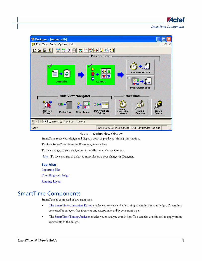
Figure 1 · Design Flow Window
SmartTime reads your design and displays post- or pre-layout timing information.
To close SmartTime, from the File menu, choose Exit.
To save changes to your design, from the File menu, choose Commit.
Note: To save changes to disk, you must also save your changes in Designer.
See Also Importing Files
Compiling your design
Running Layout
SmartTime Components SmartTime is composed of two main tools:
• The SmartTime Constraints Editor enables you to view and edit timing constraints in your design. Constraints
are sorted by category (requirements and exceptions) and by constraint type.
• The SmartTime Timing Analyzer enables you to analyze your design. You can also use this tool to apply timing
constraints to the design.
Welcome to SmartTime
12 SmartTime v8.4 User’s Guide
You can navigate between the SmartTime Constraints Editor and SmartTime Timing Analyzer by choosing Tools >
Constraints Editor > Scenario or Tools > Timing Analyzer > Maximum Delay Analysis or Minimum Delay Analysis.
Tip: You can use the Timing Analyzer icon or Constraints Editor icon to toggle between the Timing
Constraints View and Timing Analysis View.
With SmartTime, you can:
• Browse through your design’s various clock domains to examine the timing paths and identify those that violate
your timing requirements
• Add and modify timing requirements and exceptions
• Set constraints on a specific pin or a specific set of paths
• Cross-probe objects and paths with NetlistViewer, ChipPlanner, and ChipEditor tools
• Create customizable timing reports
• Navigate directly to the paths responsible for violating your timing requirements
SmartTime Constraint Scenario A constraint scenario is an independent set of constraints. By default a scenario is created as Primary Scenario to hold all
timing constraints defined by the user. This scenario will be used during both analysis and TDPR. Multiple scenarios
can be created within SmartTime. The scenario used for analysis and the scenario used for TDPR can be selected from
the list of available scenarios. Only one scenario can be used for analysis at a time. If multiple scenarios are created they
will be displayed in separate Constraint Editor windows.
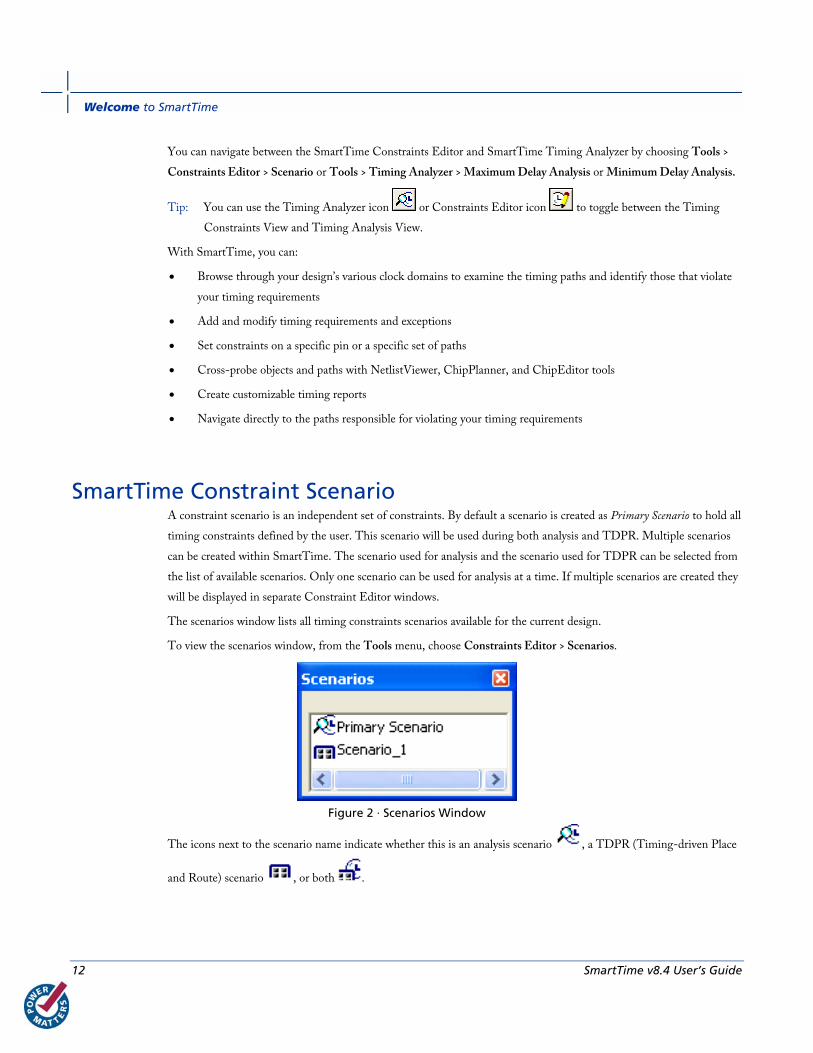
The scenarios window lists all timing constraints scenarios available for the current design.
To view the scenarios window, from the Tools menu, choose Constraints Editor > Scenarios.
Figure 2 · Scenarios Window
The icons next to the scenario name indicate whether this is an analysis scenario , a TDPR (Timing-driven Place
and Route) scenario , or both .
Setting SmartTime Options
SmartTime v8.4 User’s Guide 13
To copy a constraint from one scenario to the other, select the constraint in the Constraints Editor, and from the right-
click menu, select Copy Constraints to Scenario > <scenario_name>.
From the scenarios window, if no scenario is selected, click and from the right-click menu, select:
• Add scenario: to add a new scenario. This option is also available from the Tools> Constraints Editor > New
Scenario
• Allow docking: to allow docking for this window
• Dock this window: to dock this window
• Hide: to hide this window
From the scenarios window you can select a scenario and from the right-click menu, select:
• Use for Analysis: to use the selected scenario for Timing Analyzer. This command is also available from the
Advanced tab in the SmartTime Options dialog box
• Use for TDPR: to use the selected scenario for Timing-driven Layout. This command is also available from the
Advanced tab in the SmartTime Options dialog box, and from the Layout options dialog box
• Show constraints: to see the constraints for the selected scenario. This option is also available from the Tools>
Constraints Editor > <scenario name>
• Clone scenario: to create a new scenario with a set of constraints based on an existing scenario
• Delete scenario: to delete the selected scenario
• Rename scenario: to rename the selected scenario
You can also select multiple scenarios from the scenarios window, but only the following options will be available from
the right-click menu:
• Show constraints: to see the constraints for the selected scenarios
• Clone scenario: to create new scenarios with a set of constraints based on existing scenarios
• Delete scenario: to delete the selected scenario. This option will only be available if at least one of the scenarios is
not selected.
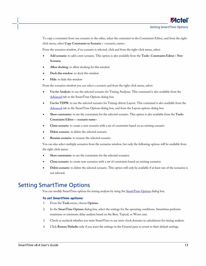
Setting SmartTime Options You can modify SmartTime options for timing analysis by using the SmartTime Options dialog box.
To set SmartTime options:
1. From the Tools menu, choose Options.
2. In the SmartTime Options dialog box, select the settings for the operating conditions. Smarttime performs
maximum or minimum delay analysis based on the Best, Typical, or Worst case.
3. Check or uncheck whether you want SmartTime to use inter-clock domains in calculations for timing analysis.
4. Click Restore Defaults only if you want the settings in the General pane to revert to their default settings.
Welcome to SmartTime
14 SmartTime v8.4 User’s Guide
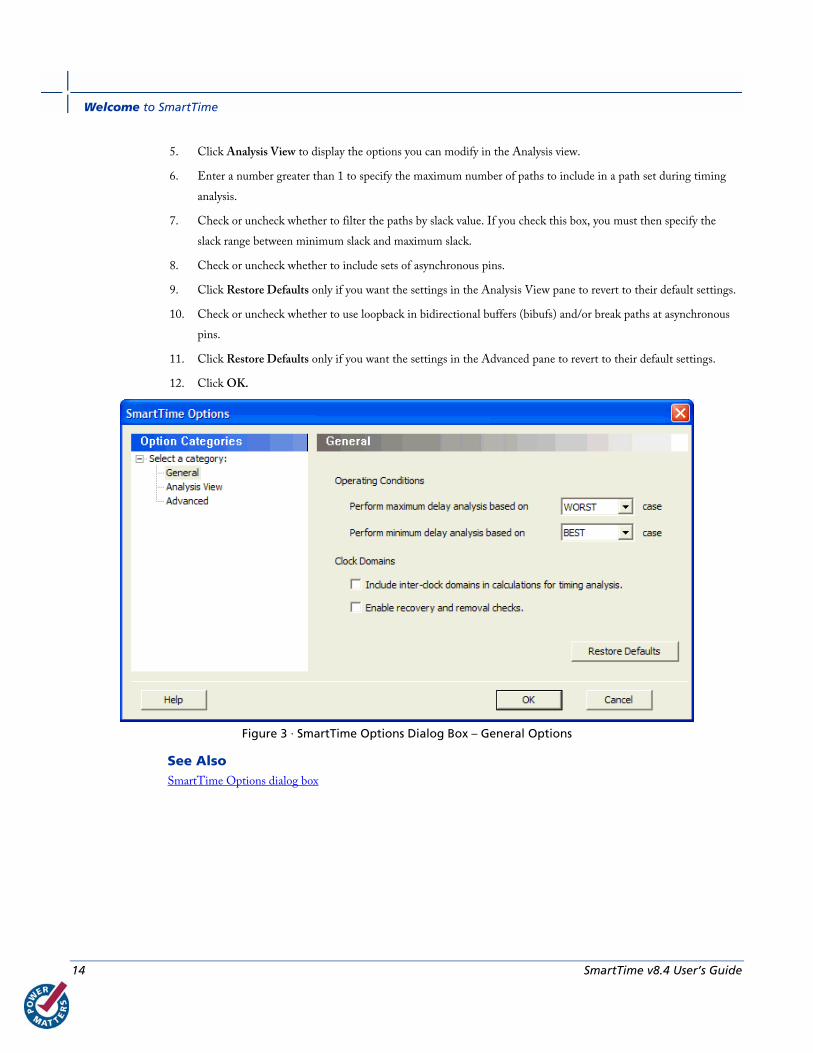
5. Click Analysis View to display the options you can modify in the Analysis view.
6. Enter a number greater than 1 to specify the maximum number of paths to include in a path set during timing
analysis.
7. Check or uncheck whether to filter the paths by slack value. If you check this box, you must then specify the
slack range between minimum slack and maximum slack.
8. Check or uncheck whether to include sets of asynchronous pins.
9. Click Restore Defaults only if you want the settings in the Analysis View pane to revert to their default settings.
10. Check or uncheck whether to use loopback in bidirectional buffers (bibufs) and/or break paths at asynchronous
pins.
11. Click Restore Defaults only if you want the settings in the Advanced pane to revert to their default settings.
12. Click OK.
Figure 3 · SmartTime Options Dialog Box – General Options
See Also SmartTime Options dialog box
SmartTime v8.4 User’s Guide 15
SmartTime Tutorial
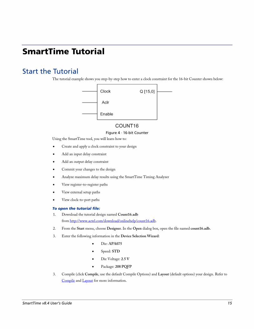
Start the Tutorial The tutorial example shows you step-by-step how to enter a clock constraint for the 16-bit Counter shown below:
Figure 4 · 16-bit Counter
Using the SmartTime tool, you will learn how to:
• Create and apply a clock constraint to your design
• Add an input delay constraint
• Add an output delay constraint
• Commit your changes to the design
• Analyze maximum delay results using the SmartTime Timing Analyzer
• View register-to-register paths
• View external setup paths
• View clock-to-port paths
To open the tutorial file:
1. Download the tutorial design named Count16.adb
from http://www.actel.com/download/onlinehelp/count16.adb.
2. From the Start menu, choose Designer. In the Open dialog box, open the file named count16.adb.
3. Enter the following information in the Device Selection Wizard:
• Die: APA075
• Speed: STD
• Die Voltage: 2.5 V
• Package: 208 PQFP
3. Compile (click Compile, use the default Compile Options) and Layout (default options) your design. Refer to
Compile and Layout for more information.
SmartTime Tutorial
16 SmartTime v8.4 User’s Guide
You are ready to create your clock constraints.
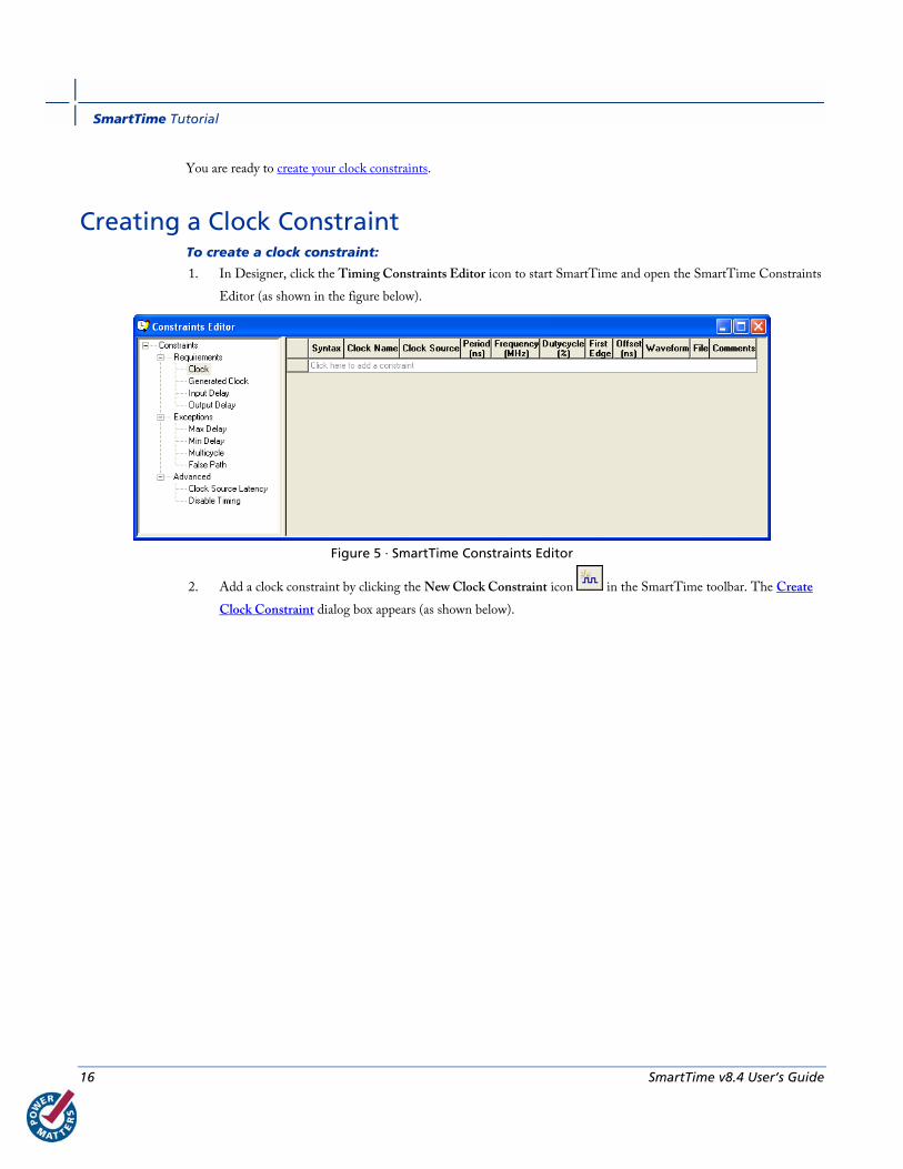
Creating a Clock Constraint To create a clock constraint:
1. In Designer, click the Timing Constraints Editor icon to start SmartTime and open the SmartTime Constraints
Editor (as shown in the figure below).
Figure 5 · SmartTime Constraints Editor
2. Add a clock constraint by clicking the New Clock Constraint icon in the SmartTime toolbar. The Create
Clock Constraint dialog box appears (as shown below).

Creating a Clock Constraint
SmartTime v8.4 User’s Guide 17
Figure 6 · Create Clock Constraint Dialog Box
3. Select the Clock pin from the pull-down menu in the Clock source field, or click the Browse button to open the
Choose the Clock Source Pin dialog box, select the Clock pin and click OK.
4. Modify the Clock Name. The name of the first clock source is provided as default.
5. Type 100 in the Period field of the Create Clock Constraint box and accept all other default values. Click OK to
close the dialog box.
Figure 7 · Create Clock Constraint Dialog Box With Values
SmartTime Tutorial
18 SmartTime v8.4 User’s Guide
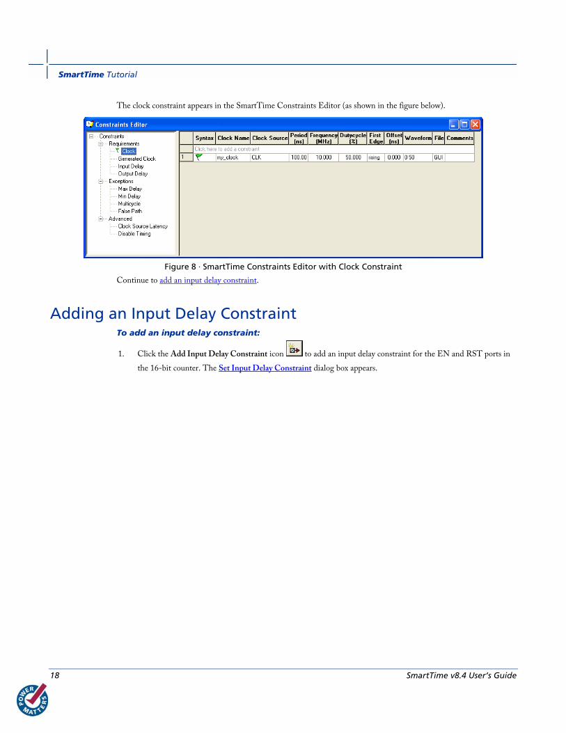
The clock constraint appears in the SmartTime Constraints Editor (as shown in the figure below).
Figure 8 · SmartTime Constraints Editor with Clock Constraint
Continue to add an input delay constraint.
Adding an Input Delay Constraint To add an input delay constraint:
1. Click the Add Input Delay Constraint icon to add an input delay constraint for the EN and RST ports in
the 16-bit counter. The Set Input Delay Constraint dialog box appears.
Adding an Input Delay Constraint
SmartTime v8.4 User’s Guide 19
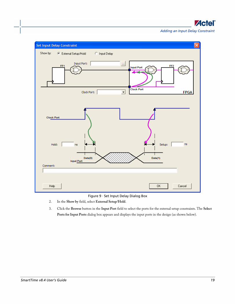
Figure 9 · Set Input Delay Dialog Box
2. In the Show by field, select External Setup/Hold.
3. Click the Browse button in the Input Port field to select the ports for the external setup constraints. The Select
Ports for Input Ports dialog box appears and displays the input ports in the design (as shown below).
SmartTime Tutorial
20 SmartTime v8.4 User’s Guide
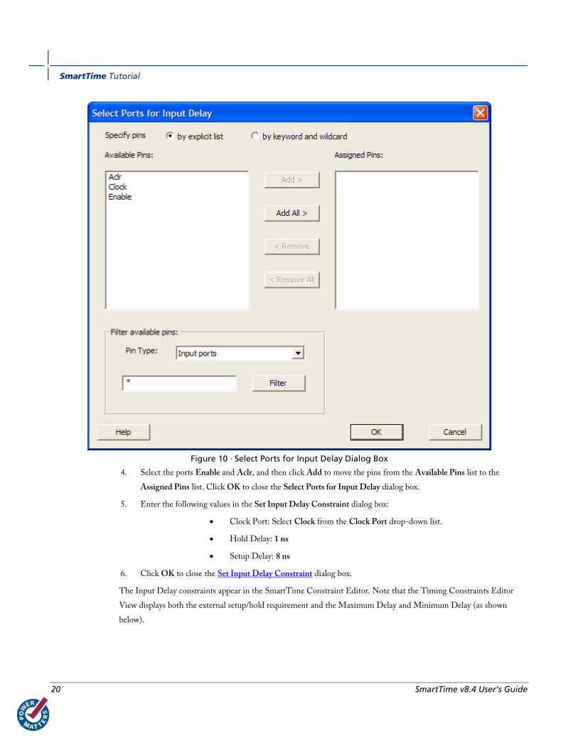
Figure 10 · Select Ports for Input Delay Dialog Box
4. Select the ports Enable and Aclr, and then click Add to move the pins from the Available Pins list to the
Assigned Pins list. Click OK to close the Select Ports for Input Delay dialog box.
5. Enter the following values in the Set Input Delay Constraint dialog box:
• Clock Port: Select Clock from the Clock Port drop-down list.
• Hold Delay: 1 ns
• Setup Delay: 8 ns
6. Click OK to close the Set Input Delay Constraint dialog box.
The Input Delay constraints appear in the SmartTime Constraint Editor. Note that the Timing Constraints Editor
View displays both the external setup/hold requirement and the Maximum Delay and Minimum Delay (as shown
below).

Adding an Output Delay Constraint
SmartTime v8.4 User’s Guide 21
Figure 11 · SmartTime Constraints Editor with Input Delay Constraint
Continue to add an output delay constraint.
Adding an Output Delay Constraint To add an output delay constraint:
1. Click the Add Output Delay Constraint icon in the SmartTime toolbar. The Set Output Delay Constraint
dialog box appears.
SmartTime Tutorial
22 SmartTime v8.4 User’s Guide
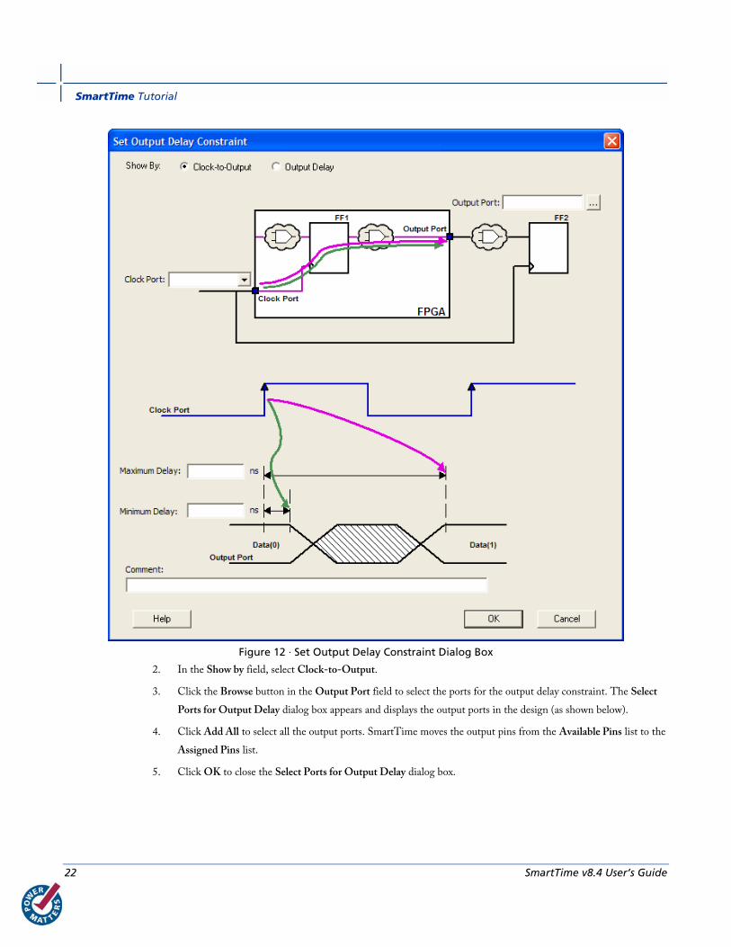
Figure 12 · Set Output Delay Constraint Dialog Box
2. In the Show by field, select Clock-to-Output.
3. Click the Browse button in the Output Port field to select the ports for the output delay constraint. The Select
Ports for Output Delay dialog box appears and displays the output ports in the design (as shown below).
4. Click Add All to select all the output ports. SmartTime moves the output pins from the Available Pins list to the
Assigned Pins list.
5. Click OK to close the Select Ports for Output Delay dialog box.
Adding an Output Delay Constraint
SmartTime v8.4 User’s Guide 23
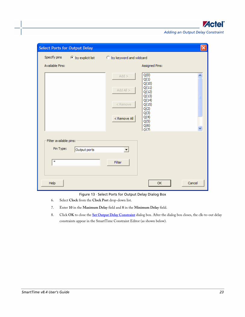
Figure 13 · Select Ports for Output Delay Dialog Box
6. Select Clock from the Clock Port drop-down list.
7. Enter 10 in the Maximum Delay field and 8 in the Minimum Delay field.
8. Click OK to close the Set Output Delay Constraint dialog box. After the dialog box closes, the clk-to-out delay
constraints appear in the SmartTime Constraint Editor (as shown below).

SmartTime Tutorial
24 SmartTime v8.4 User’s Guide
Figure 14 · SmartTime Constraints Editor with Output Delay Constraint
You must commit your changes in SmartTime before you can analyze timing in your design. Click the Commit icon
in the SmartTime toolbar to save your constraints.
You are ready to analyze your design.
Analyzing the Maximum Operating Frequency The Maximum Delay Analysis View indicates the maximum operating frequency for a design and displays any setup
violations.
To perform the Maximum Delay Analysis:
Click the Timing Analyzer icon in the Designer interface to open the SmartTime Timing Analyzer. The
Maximum Delay Analysis View appears. A green flag next to the name of the clock indicates there are no timing
violations for that clock domain (as shown below).
The SmartTime Maximum Delay Analysis View displays the maximum operating frequency for a design and any setup
violations.
Viewing Register-to-Register Paths
SmartTime v8.4 User’s Guide 25
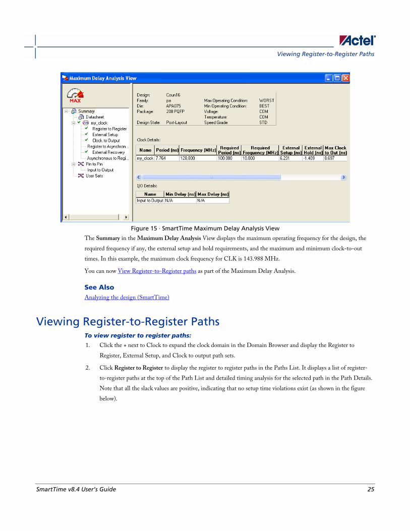
Figure 15 · SmartTime Maximum Delay Analysis View
The Summary in the Maximum Delay Analysis View displays the maximum operating frequency for the design, the
required frequency if any, the external setup and hold requirements, and the maximum and minimum clock-to-out
times. In this example, the maximum clock frequency for CLK is 143.988 MHz.
You can now View Register-to-Register paths as part of the Maximum Delay Analysis.
See Also Analyzing the design (SmartTime)
Viewing Register-to-Register Paths To view register to register paths:
1. Click the + next to Clock to expand the clock domain in the Domain Browser and display the Register to
Register, External Setup, and Clock to output path sets.
2. Click Register to Register to display the register to register paths in the Paths List. It displays a list of register-
to-register paths at the top of the Path List and detailed timing analysis for the selected path in the Path Details.
Note that all the slack values are positive, indicating that no setup time violations exist (as shown in the figure
below).
SmartTime Tutorial
26 SmartTime v8.4 User’s Guide
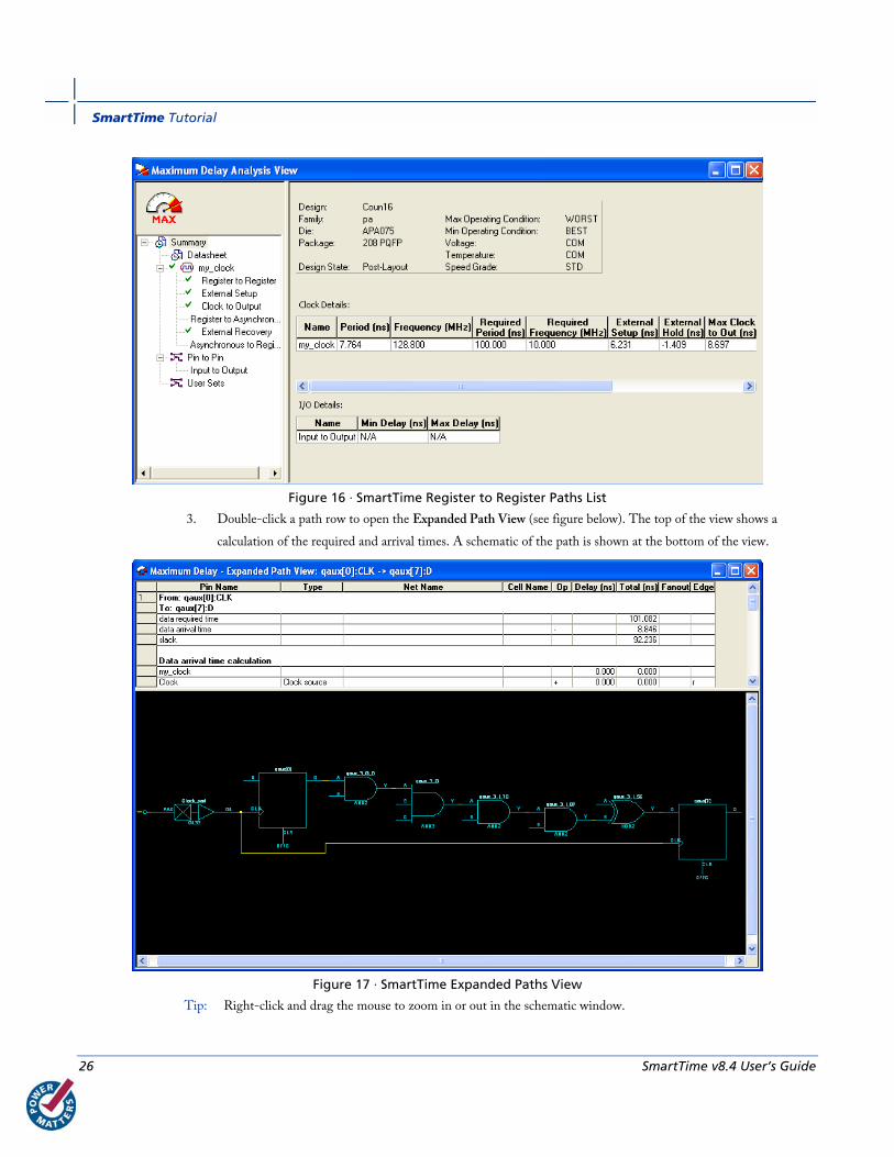
Figure 16 · SmartTime Register to Register Paths List
3. Double-click a path row to open the Expanded Path View (see figure below). The top of the view shows a
calculation of the required and arrival times. A schematic of the path is shown at the bottom of the view.
Figure 17 · SmartTime Expanded Paths View
Tip: Right-click and drag the mouse to zoom in or out in the schematic window.
Viewing External Setup Paths
SmartTime v8.4 User’s Guide 27
Close the Expanded Paths View.
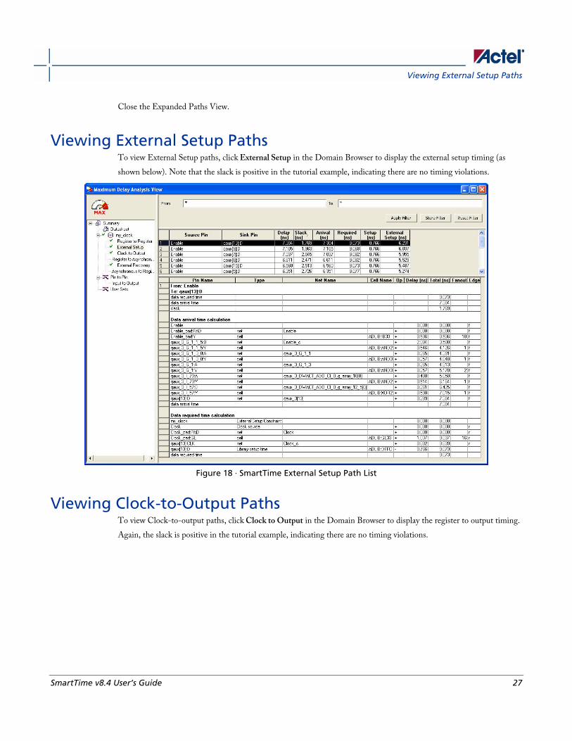
Viewing External Setup Paths To view External Setup paths, click External Setup in the Domain Browser to display the external setup timing (as
shown below). Note that the slack is positive in the tutorial example, indicating there are no timing violations.
Figure 18 · SmartTime External Setup Path List
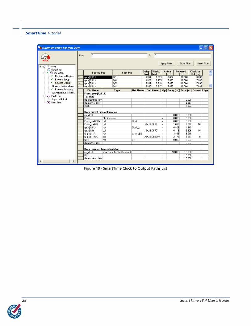
Viewing Clock-to-Output Paths To view Clock-to-output paths, click Clock to Output in the Domain Browser to display the register to output timing.
Again, the slack is positive in the tutorial example, indicating there are no timing violations.
SmartTime Tutorial
28 SmartTime v8.4 User’s Guide
Figure 19 · SmartTime Clock to Output Paths List

SmartTime v8.4 User’s Guide 29
SmartTime Constraints Editor
Components of the SmartTime Constraints Editor SmartTime Constraints Editor is a tool in the Designer software that enables you to create, view, and edit timing
constraints of the selected scenario for use with SmartTime timing analysis and timing-driven optimization tools. This
editor includes powerful visual dialogs that guide you toward capturing your timing requirements and timing exceptions
quickly and correctly. In addition, it is closely connected to the SmartTime Timing Analysis View, which enables you
to analyze the impact of constraint changes.
Figure 20 · SmartTime Constraints Editor View
Constraint Hierarchy Browser The SmartTime Constraints Editor window is divided into a Constraint Browser and a Constraint List. The
Constraint Browser categorizes constraints based on requirements and exceptions, while the Constraint List provides
details about each constraint and enables the user to add, edit and delete constraints.
You can perform the following tasks in the SmartTime Constraints View:
• Select a constraint type from the Constraint Browser and create or edit the constraint.
• Add a new constraint and check the syntax.
• Click or double-click a constraint in the Constraint List to edit and check the syntax of the selected constraint.
• Select a row and right-click to display the shortcut menu, which you can use to edit, delete, or copy the selected
constraint to a spreadsheet.
• Select the entire spreadsheet and copy it to another spreadsheet.
SmartTime Constraints Editor
30 SmartTime v8.4 User’s Guide
See Also Editable Grid and Quick Adder
SmartTime scenarios
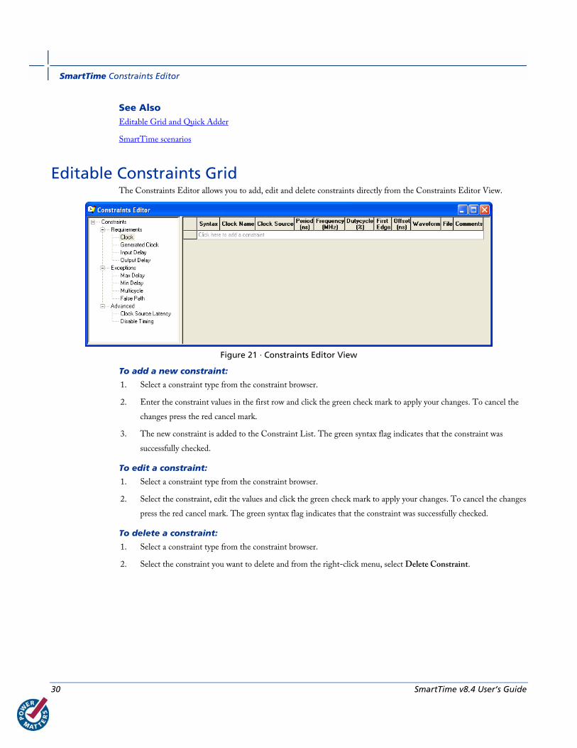
Editable Constraints Grid The Constraints Editor allows you to add, edit and delete constraints directly from the Constraints Editor View.
Figure 21 · Constraints Editor View
To add a new constraint:
1. Select a constraint type from the constraint browser.
2. Enter the constraint values in the first row and click the green check mark to apply your changes. To cancel the
changes press the red cancel mark.
3. The new constraint is added to the Constraint List. The green syntax flag indicates that the constraint was
successfully checked.
To edit a constraint:
1. Select a constraint type from the constraint browser.
2. Select the constraint, edit the values and click the green check mark to apply your changes. To cancel the changes
press the red cancel mark. The green syntax flag indicates that the constraint was successfully checked.
To delete a constraint:
1. Select a constraint type from the constraint browser.
2. Select the constraint you want to delete and from the right-click menu, select Delete Constraint.
Constraint Wizard
SmartTime v8.4 User’s Guide 31
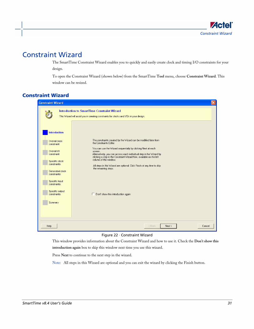
Constraint Wizard The SmartTime Constraint Wizard enables you to quickly and easily create clock and timing I/O constraints for your
design.
To open the Constraint Wizard (shown below) from the SmartTime Tool menu, choose Constraint Wizard. This
window can be resized.
Constraint Wizard
Figure 22 · Constraint Wizard
This window provides information about the Constraint Wizard and how to use it. Check the Don’t show this
introduction again box to skip this window next time you use this wizard.
Press Next to continue to the next step in the wizard.
Note: All steps in this Wizard are optional and you can exit the wizard by clicking the Finish button.
SmartTime Constraints Editor
32 SmartTime v8.4 User’s Guide
Overall Clock Constraint
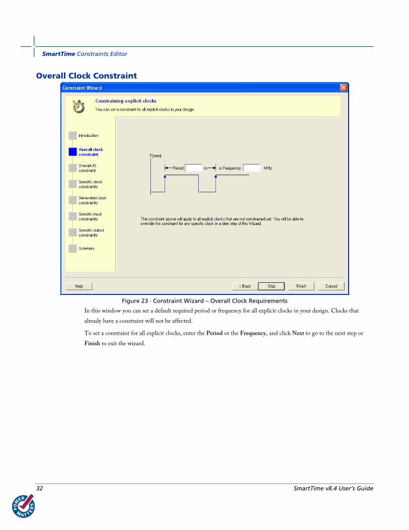
Figure 23 · Constraint Wizard – Overall Clock Requirements
In this window you can set a default required period or frequency for all explicit clocks in your design. Clocks that
already have a constraint will not be affected.
To set a constraint for all explicit clocks, enter the Period or the Frequency, and click Next to go to the next step or
Finish to exit the wizard.
Constraint Wizard
SmartTime v8.4 User’s Guide 33
Overall I/O Constraint
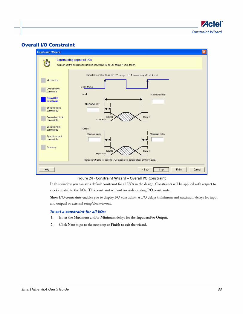
Figure 24 · Constraint Wizard – Overall I/O Constraint
In this window you can set a default constraint for all I/Os in the design. Constraints will be applied with respect to
clocks related to the I/Os. This constraint will not override existing I/O constraints.
Show I/O constraints enables you to display I/O constraints as I/O delays (minimum and maximum delays for input
and output) or external setup/clock-to-out.
To set a constraint for all I/Os:
1. Enter the Maximum and/or Minimum delays for the Input and/or Output.
2. Click Next to go to the next step or Finish to exit the wizard.

SmartTime Constraints Editor
34 SmartTime v8.4 User’s Guide
Specific Clock Constraints
Figure 25 · Constraint Wizard – Specific Clock Constraints
In this window you can set a period and I/O timing constraints for a specific clock domain. All I/Os within the domain
will be affected by the I/O timing constraints. You can modify the constraints from the grid.
To add a constraint for a potential clock:
1. Click the first row in the grid, enter the constraint information, and click the green check mark.
2. Click Next to go to the next step or Finish to exit the wizard.
Note: This option is available only when there is a potential clock in your design.
Constraint Wizard
SmartTime v8.4 User’s Guide 35
Generated Clock Constraints
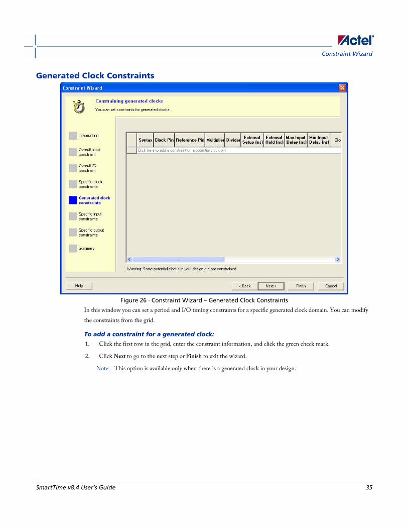
Figure 26 · Constraint Wizard – Generated Clock Constraints
In this window you can set a period and I/O timing constraints for a specific generated clock domain. You can modify
the constraints from the grid.
To add a constraint for a generated clock:
1. Click the first row in the grid, enter the constraint information, and click the green check mark.
2. Click Next to go to the next step or Finish to exit the wizard.
Note: This option is available only when there is a generated clock in your design.
SmartTime Constraints Editor
36 SmartTime v8.4 User’s Guide
Specific Input Constraints
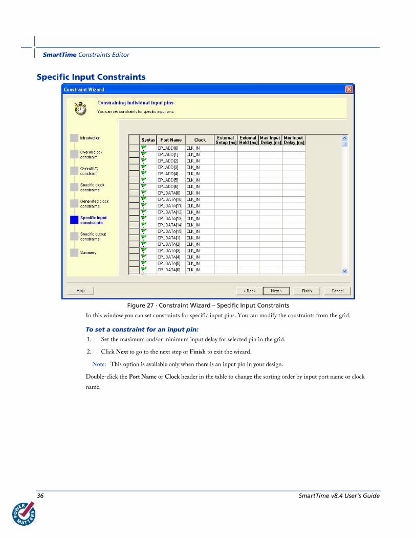
Figure 27 · Constraint Wizard – Specific Input Constraints
In this window you can set constraints for specific input pins. You can modify the constraints from the grid.
To set a constraint for an input pin:
1. Set the maximum and/or minimum input delay for selected pin in the grid.
2. Click Next to go to the next step or Finish to exit the wizard.
Note: This option is available only when there is an input pin in your design.
Double-click the Port Name or Clock header in the table to change the sorting order by input port name or clock
name.
Constraint Wizard
SmartTime v8.4 User’s Guide 37
Specific Output Constraints
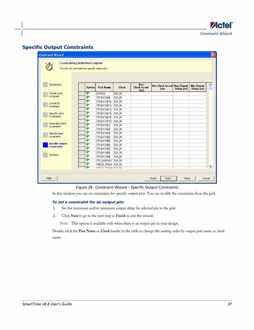
Figure 28 · Constraint Wizard – Specific Output Constraints
In this window you can set constraints for specific output pins. You can modify the constraints from the grid.
To set a constraint for an output pin:
1. Set the maximum and/or minimum output delay for selected pin in the grid.
2. Click Next to go to the next step or Finish to exit the wizard.
Note: This option is available only when there is an output pin in your design.
Double-click the Port Name or Clock header in the table to change the sorting order by output port name or clock
name.

SmartTime Constraints Editor
38 SmartTime v8.4 User’s Guide
Summary
Figure 29 · Constraint Wizard – Summary
This window summarizes the requirements specified in the wizard and information about all clock and I/O constraints
in the design.
Click Finish to create the constraints.
See Also Editable Grid and Quick Adder
Using Clock Types Clock constraints enable you to specify your clock sources and clock requirements, such as the frequency and duty cycle.
SmartTime detects possible clocks by tracing back the design from the clock pins of all sequential components until it
finds an input port, the output of another sequential element, or the output of a PLL. SmartTime classifies clock
sources into three types:
• Explicit clocks
• Potential clocks
• Clock network
Using Clock Types
SmartTime v8.4 User’s Guide 39
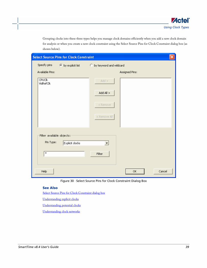
Grouping clocks into these three types helps you manage clock domains efficiently when you add a new clock domain
for analysis or when you create a new clock constraint using the Select Source Pins for Clock Constraint dialog box (as
shown below).
Figure 30 · Select Source Pins for Clock Constraint Dialog Box
See Also Select Source Pins for Clock Constraint dialog box
Understanding explicit clocks
Understanding potential clocks
Understanding clock networks
SmartTime Constraints Editor
40 SmartTime v8.4 User’s Guide
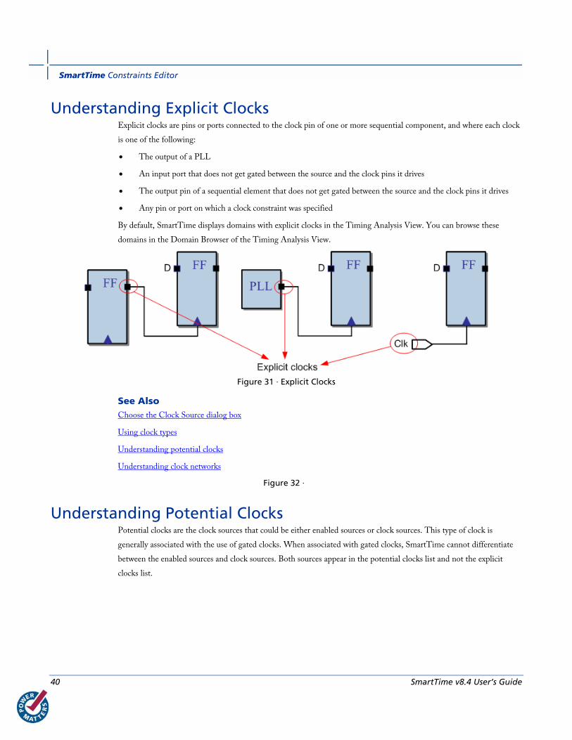
Understanding Explicit Clocks Explicit clocks are pins or ports connected to the clock pin of one or more sequential component, and where each clock
is one of the following:
• The output of a PLL
• An input port that does not get gated between the source and the clock pins it drives
• The output pin of a sequential element that does not get gated between the source and the clock pins it drives
• Any pin or port on which a clock constraint was specified
By default, SmartTime displays domains with explicit clocks in the Timing Analysis View. You can browse these
domains in the Domain Browser of the Timing Analysis View.
Figure 31 · Explicit Clocks
See Also Choose the Clock Source dialog box
Using clock types
Understanding potential clocks
Understanding clock networks
Figure 32 ·
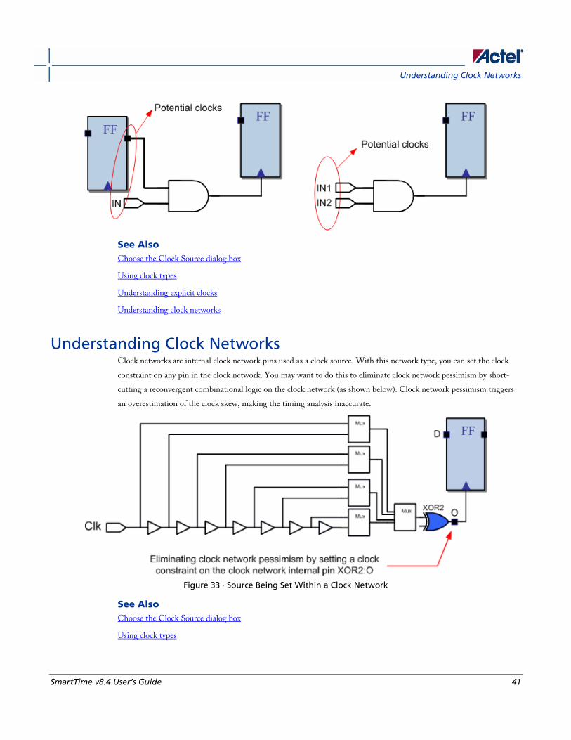
Understanding Potential Clocks Potential clocks are the clock sources that could be either enabled sources or clock sources. This type of clock is
generally associated with the use of gated clocks. When associated with gated clocks, SmartTime cannot differentiate
between the enabled sources and clock sources. Both sources appear in the potential clocks list and not the explicit
clocks list.
Understanding Clock Networks
SmartTime v8.4 User’s Guide 41
See Also Choose the Clock Source dialog box
Using clock types
Understanding explicit clocks
Understanding clock networks
Understanding Clock Networks Clock networks are internal clock network pins used as a clock source. With this network type, you can set the clock
constraint on any pin in the clock network. You may want to do this to eliminate clock network pessimism by short-
cutting a reconvergent combinational logic on the clock network (as shown below). Clock network pessimism triggers
an overestimation of the clock skew, making the timing analysis inaccurate.
Figure 33 · Source Being Set Within a Clock Network
See Also Choose the Clock Source dialog box
Using clock types
SmartTime Constraints Editor
42 SmartTime v8.4 User’s Guide
Understanding potential clocks
Understanding clock networks
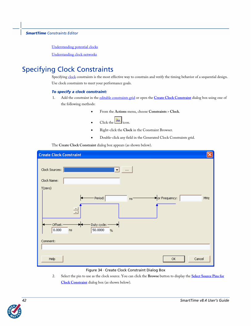
Specifying Clock Constraints Specifying clock constraints is the most effective way to constrain and verify the timing behavior of a sequential design.
Use clock constraints to meet your performance goals.
To specify a clock constraint:
1. Add the constraint in the editable constraints grid or open the Create Clock Constraint dialog box using one of
the following methods:
• From the Actions menu, choose Constraints > Clock.
• Click the icon.
• Right-click the Clock in the Constraint Browser.
• Double-click any field in the Generated Clock Constraints grid.
The Create Clock Constraint dialog box appears (as shown below).
Figure 34 · Create Clock Constraint Dialog Box
2. Select the pin to use as the clock source. You can click the Browse button to display the Select Source Pins for
Clock Constraint dialog box (as shown below).
Specifying Clock Constraints
SmartTime v8.4 User’s Guide 43
Note: Do not select a source pin when you specify a virtual clock. Virtual clocks can be used to define a clock
outside the FPGA that it is used to synchronize I/Os.
Use the Choose the Clock Source Pin dialog box to display a list of source pins from which you can choose. By default,
it displays the explicit clock sources of the design. To choose other pins in the design as clock source pins, select Filter
available objects - Pin Type as Explicit clocks, Potential clocks, Input ports, All Pins, All Nets, Pins on clock
network,or Nets in clock network. To display a subset of the displayed clock source pins, you can create and apply a
filter.
Multiple source pins can be specified for the same clock when a single clock is entering the FPGA using multiple
inputs with different delays.
Click OK to save these dialog box settings.
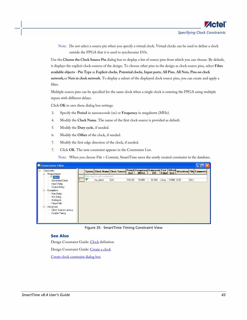
3. Specify the Period in nanoseconds (ns) or Frequency in megahertz (MHz).
4. Modify the Clock Name. The name of the first clock source is provided as default.
5. Modify the Duty cycle, if needed.
6. Modify the Offset of the clock, if needed.
7. Modify the first edge direction of the clock, if needed.
7. Click OK. The new constraint appears in the Constraints List.
Note: When you choose File > Commit, SmartTime saves the newly created constraint in the database.
Figure 35 · SmartTime Timing Constraint View
See Also Design Constraint Guide: Clock definition
Design Constraint Guide: Create a clock
Create clock constraint dialog box
SmartTime Constraints Editor
44 SmartTime v8.4 User’s Guide
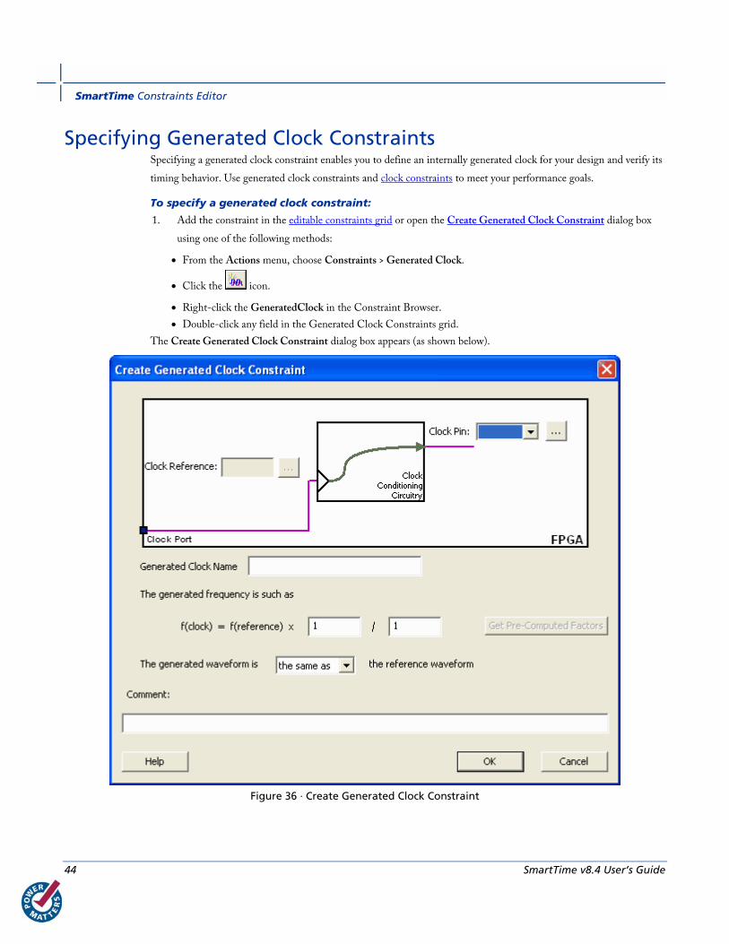
Specifying Generated Clock Constraints Specifying a generated clock constraint enables you to define an internally generated clock for your design and verify its
timing behavior. Use generated clock constraints and clock constraints to meet your performance goals.
To specify a generated clock constraint:
1. Add the constraint in the editable constraints grid or open the Create Generated Clock Constraint dialog box
using one of the following methods:
• From the Actions menu, choose Constraints > Generated Clock.
• Click the icon.
• Right-click the GeneratedClock in the Constraint Browser.
• Double-click any field in the Generated Clock Constraints grid.
The Create Generated Clock Constraint dialog box appears (as shown below).
Figure 36 · Create Generated Clock Constraint

Specifying Generated Clock Constraints
SmartTime v8.4 User’s Guide 45
2. Select a Clock Pin to use as the generated clock source. To display a list of available generated clock source pins,
click the Browse button. The Select Generated Clock Source dialog box appears (as shown below).
Figure 37 · Select Generated Clock Source Dialog Box
3. Modify the Clock Name if necessary.
4. Click OK to save these dialog box settings.
5. Specify a Clock Reference. To display a list of available clock reference pins, click the Browse button. The Select
Generated Clock Reference dialog box appears.
5. Click OK to save this dialog box settings.
6. Specify the values to calculate the generated frequency: a multiplication factor and/or a division factor (both
positive integers).
7. Specify the first edge of the generated waveform either same as or inverted with respect to the reference
waveform.
8. Click OK. The new constraint appears in the Constraints List.
Tip: From the File menu, choose Commit to save the newly created constraint in the database.
SmartTime Constraints Editor
46 SmartTime v8.4 User’s Guide
See Also Design Constraint Guide: Clock definition
Design Constraint Guide: Create a clock
Create clock constraint dialog box
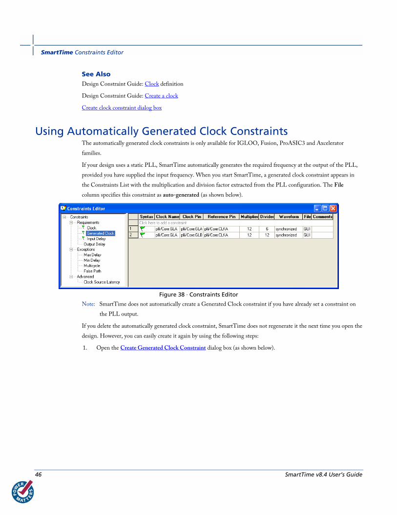
Using Automatically Generated Clock Constraints The automatically generated clock constraints is only available for IGLOO, Fusion, ProASIC3 and Axcelerator
families.
If your design uses a static PLL, SmartTime automatically generates the required frequency at the output of the PLL,
provided you have supplied the input frequency. When you start SmartTime, a generated clock constraint appears in
the Constraints List with the multiplication and division factor extracted from the PLL configuration. The File
column specifies this constraint as auto-generated (as shown below).
Figure 38 · Constraints Editor
Note: SmartTime does not automatically create a Generated Clock constraint if you have already set a constraint on
the PLL output.
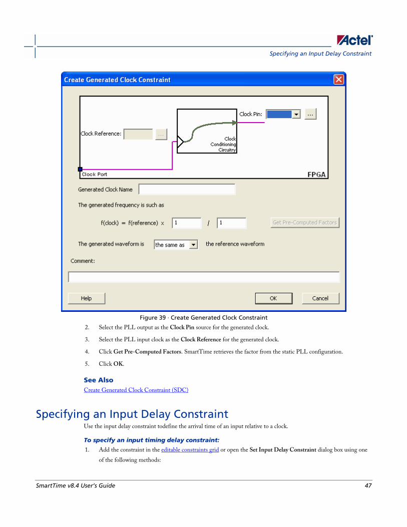
If you delete the automatically generated clock constraint, SmartTime does not regenerate it the next time you open the
design. However, you can easily create it again by using the following steps:
1. Open the Create Generated Clock Constraint dialog box (as shown below).
Specifying an Input Delay Constraint
SmartTime v8.4 User’s Guide 47
Figure 39 · Create Generated Clock Constraint
2. Select the PLL output as the Clock Pin source for the generated clock.
3. Select the PLL input clock as the Clock Reference for the generated clock.
4. Click Get Pre-Computed Factors. SmartTime retrieves the factor from the static PLL configuration.
5. Click OK.
See Also Create Generated Clock Constraint (SDC)
Specifying an Input Delay Constraint Use the input delay constraint todefine the arrival time of an input relative to a clock.
To specify an input timing delay constraint:
1. Add the constraint in the editable constraints grid or open the Set Input Delay Constraint dialog box using one
of the following methods:

SmartTime Constraints Editor
48 SmartTime v8.4 User’s Guide
• From the SmartTime Actions menu, choose Constraints > Input Delay.
• Click the icon.
• Right-click the Input Delay in the Constraint Browser.
• Double-click any field in the Input Delay Constraints grid.
The Set Input Delay Constraint dialog box appears (as shown below).
Figure 40 · Set Input Delay Dialog Box
2. Select either External Setup/Hold or Input Delay.
• External Setup/Hold enables you to enter an input delay constraint by specifying the timing budget inside the FPGA using the external setup and hold time. This is the default selection.
Note: The external hold information is currently used for analysis only and not by the optimization tools. For the basic timing analysis flow of a simple design, select External Setup/Hold.
• Input Delay enables you to enter an input delay constraint by specifying the timing budget outside the FPGA. You can enter the Maximum Delay, the Minimum Delay, or both.

Specifying an Input Delay Constraint
SmartTime v8.4 User’s Guide 49
Note: The Minimum Delay is currently used for analysis only and not by the optimization tools.
When you change values in one view, SmartTime automatically updates the other view.
3. Specify the Input Port or click the Browse button to display the Select Ports for Input Delay dialog box.
Figure 41 · Select Ports for Input Delay Dialog Box
3. Select the name of the input pin(s) from the Available Pins list. Choose the Pin Type from the drop-down list.
You can use the filter to narrow the pin list. You can select multiple ports in this window.
4. Click Add or Add All to move the input pin(s) from the Available Pins list to the Assigned Pins list.
5. Click OK.
The Set Input Delay Constraint dialog box displays the updated Input Port information.
SmartTime Constraints Editor
50 SmartTime v8.4 User’s Guide
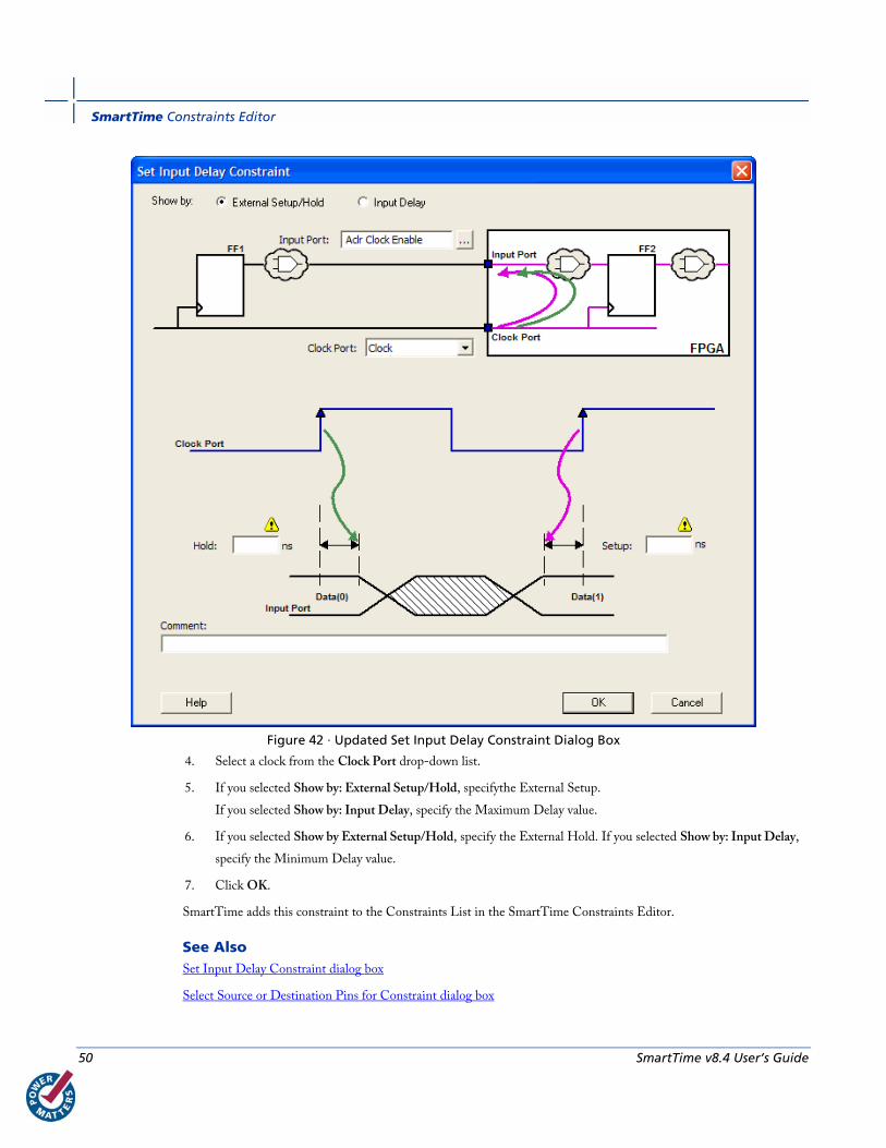
Figure 42 · Updated Set Input Delay Constraint Dialog Box
4. Select a clock from the Clock Port drop-down list.
5. If you selected Show by: External Setup/Hold, specifythe External Setup.
If you selected Show by: Input Delay, specify the Maximum Delay value.
6. If you selected Show by External Setup/Hold, specify the External Hold. If you selected Show by: Input Delay,
specify the Minimum Delay value.
7. Click OK.
SmartTime adds this constraint to the Constraints List in the SmartTime Constraints Editor.
See Also Set Input Delay Constraint dialog box
Select Source or Destination Pins for Constraint dialog box
Specifying an Output Delay Constraint
SmartTime v8.4 User’s Guide 51
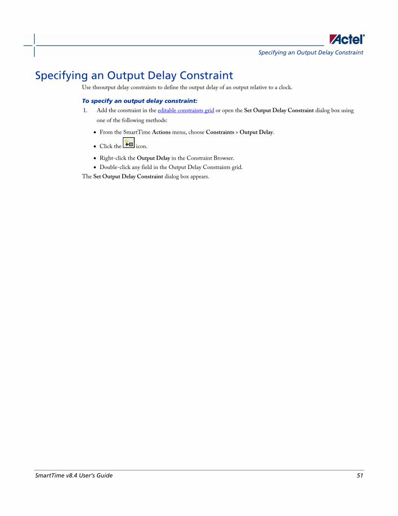
Specifying an Output Delay Constraint Use theoutput delay constraints to define the output delay of an output relative to a clock.
To specify an output delay constraint:
1. Add the constraint in the editable constraints grid or open the Set Output Delay Constraint dialog box using
one of the following methods:
• From the SmartTime Actions menu, choose Constraints > Output Delay.
• Click the icon.
• Right-click the Output Delay in the Constraint Browser.
• Double-click any field in the Output Delay Constraints grid.
The Set Output Delay Constraint dialog box appears.
SmartTime Constraints Editor
52 SmartTime v8.4 User’s Guide
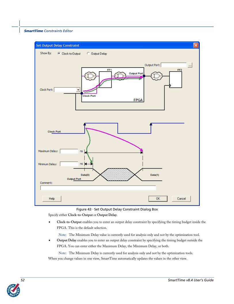
Figure 43 · Set Output Delay Constraint Dialog Box
Specify either Clock-to-Output or Output Delay.
• Clock-to-Output enables you to enter an output delay constraint by specifying the timing budget inside the
FPGA. This is the default selection.
Note: The Minimum Delay value is currently used for analysis only and not by the optimization tool.
• Output Delay enables you to enter an output delay constraint by specifying the timing budget outside the
FPGA. You can enter either the Maximum Delay, the Minimum Delay, or both.
Note: The Minimum Delay is currently used for analysis only and not by the optimization tools.
When you change values in one view, SmartTime automatically updates the values in the other view.
Specifying an Output Delay Constraint
SmartTime v8.4 User’s Guide 53
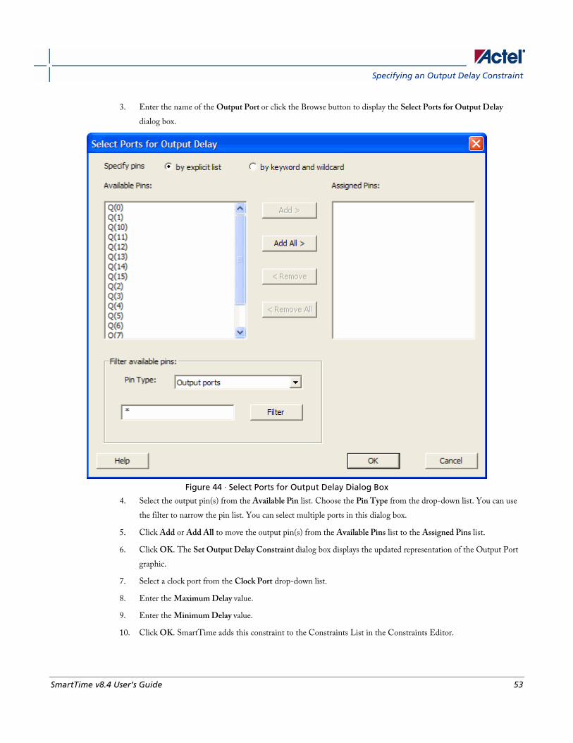
3. Enter the name of the Output Port or click the Browse button to display the Select Ports for Output Delay
dialog box.
Figure 44 · Select Ports for Output Delay Dialog Box
4. Select the output pin(s) from the Available Pin list. Choose the Pin Type from the drop-down list. You can use
the filter to narrow the pin list. You can select multiple ports in this dialog box.
5. Click Add or Add All to move the output pin(s) from the Available Pins list to the Assigned Pins list.
6. Click OK. The Set Output Delay Constraint dialog box displays the updated representation of the Output Port
graphic.
7. Select a clock port from the Clock Port drop-down list.
8. Enter the Maximum Delay value.
9. Enter the Minimum Delay value.
10. Click OK. SmartTime adds this constraint to the Constraints List in the Constraints Editor.

SmartTime Constraints Editor
54 SmartTime v8.4 User’s Guide
See Also Set Output Delay Constraint dialog box
Select Source or Destination Pins for Constraint dialog box
SmartTime v8.4 User’s Guide 55
SmartTime Timing Analyzer
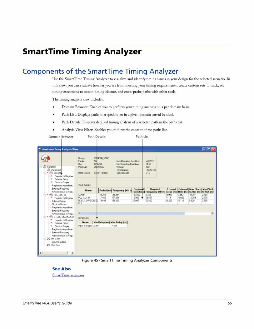
Components of the SmartTime Timing Analyzer Use the SmartTime Timing Analyzer to visualize and identify timing issues in your design for the selected scenario. In
this view, you can evaluate how far you are from meeting your timing requirements, create custom sets to track, set
timing exceptions to obtain timing closure, and cross-probe paths with other tools.
The timing analysis view includes:
• Domain Browser: Enables you to perform your timing analysis on a per domain basis.
• Path List: Displays paths in a specific set in a given domain sorted by slack.
• Path Details: Displays detailed timing analysis of a selected path in the paths list.
• Analysis View Filter: Enables you to filter the content of the paths list.
Figure 45 · SmartTime Timing Analyzer Components
See Also SmartTime scenarios
SmartTime Timing Analyzer
56 SmartTime v8.4 User’s Guide
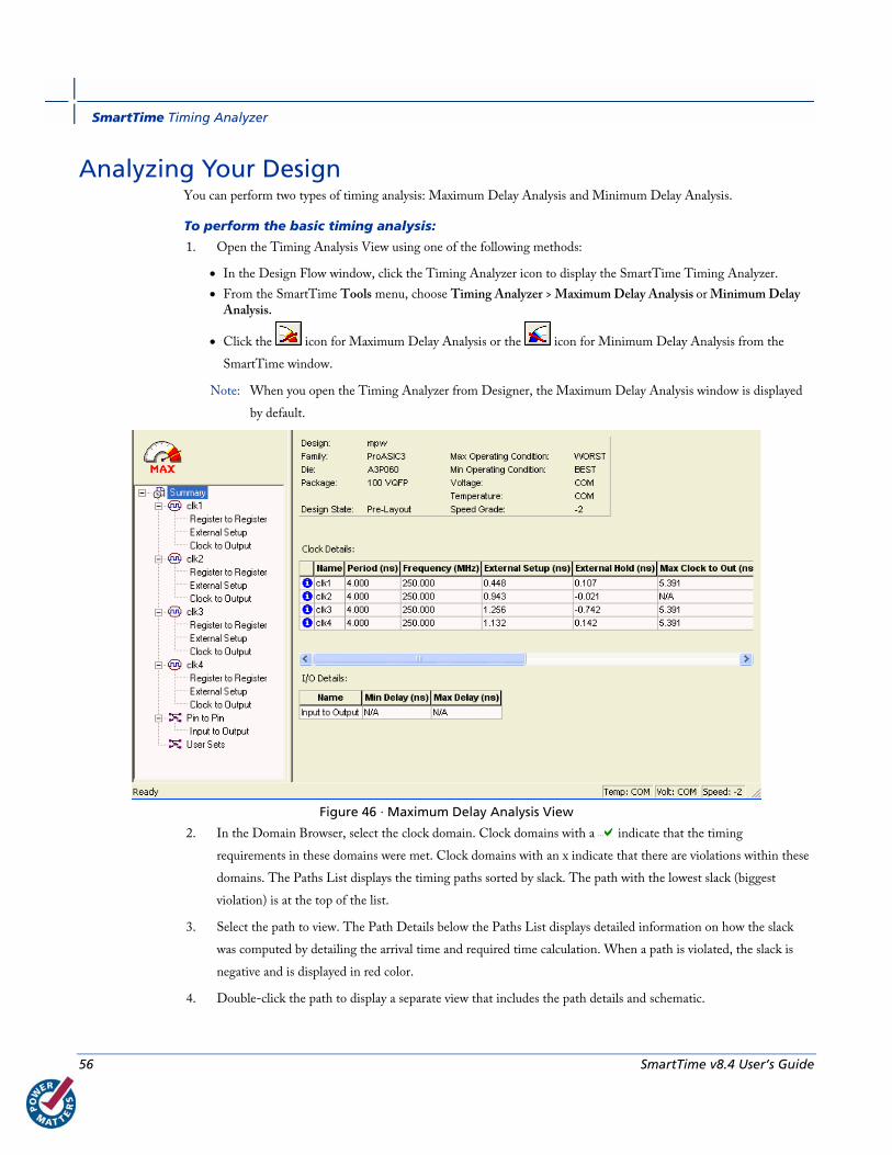
Analyzing Your Design You can perform two types of timing analysis: Maximum Delay Analysis and Minimum Delay Analysis.
To perform the basic timing analysis:
1. Open the Timing Analysis View using one of the following methods:
• In the Design Flow window, click the Timing Analyzer icon to display the SmartTime Timing Analyzer.
• From the SmartTime Tools menu, choose Timing Analyzer > Maximum Delay Analysis or Minimum Delay Analysis.
• Click the icon for Maximum Delay Analysis or the icon for Minimum Delay Analysis from the
SmartTime window.
Note: When you open the Timing Analyzer from Designer, the Maximum Delay Analysis window is displayed
by default.
Figure 46 · Maximum Delay Analysis View
2. In the Domain Browser, select the clock domain. Clock domains with a indicate that the timing
requirements in these domains were met. Clock domains with an x indicate that there are violations within these
domains. The Paths List displays the timing paths sorted by slack. The path with the lowest slack (biggest
violation) is at the top of the list.
3. Select the path to view. The Path Details below the Paths List displays detailed information on how the slack
was computed by detailing the arrival time and required time calculation. When a path is violated, the slack is
negative and is displayed in red color.
4. Double-click the path to display a separate view that includes the path details and schematic.

Performing a Bottleneck Analysis
SmartTime v8.4 User’s Guide 57
Note: In cases where the minimum pulse width of one element on the critical path limits the maximum
frequency for the clock, SmartTime displays an icon for the clock name in the Summary List. Click on the
icon to display the name of the pin that limits the clock frequency.
5. Repeat the above steps as required.
Performing a Bottleneck Analysis To perform a bottleneck analysis
1. From the SmartTime Tools menu, select Timing Analyzer > Bottleneck Analysis. The Timing Bottleneck
Analysis Options dialog box appears.
2. Select the options you wish to display and click OK.
The Bottleneck Analysis View appears in a separate window (see image below).
Figure 47 · Bottleneck Analysis View
SmartTime Timing Analyzer
58 SmartTime v8.4 User’s Guide
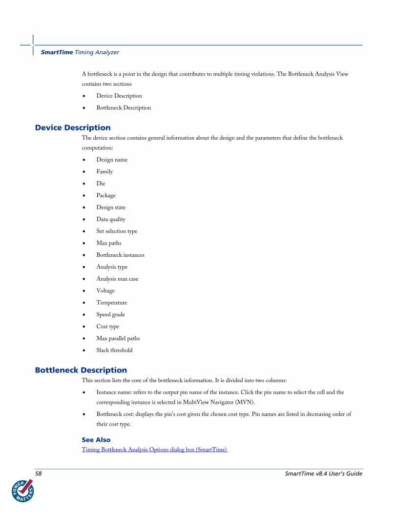
A bottleneck is a point in the design that contributes to multiple timing violations. The Bottleneck Analysis View
contains two sections
• Device Description
• Bottleneck Description
Device Description The device section contains general information about the design and the parameters that define the bottleneck
computation:
• Design name
• Family
• Die
• Package
• Design state
• Data quality
• Set selection type
• Max paths
• Bottleneck instances
• Analysis type
• Analysis max case
• Voltage
• Temperature
• Speed grade
• Cost type
• Max parallel paths
• Slack threshold
Bottleneck Description This section lists the core of the bottleneck information. It is divided into two columns:
• Instance name: refers to the output pin name of the instance. Click the pin name to select the cell and the
corresponding instance is selected in MultiView Navigator (MVN).
• Bottleneck cost: displays the pin's cost given the chosen cost type. Pin names are listed in decreasing order of
their cost type.
See Also Timing Bottleneck Analysis Options dialog box (SmartTime)
Managing Clock Domains
SmartTime v8.4 User’s Guide 59
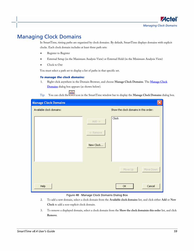
Managing Clock Domains In SmartTime, timing paths are organized by clock domains. By default, SmartTime displays domains with explicit
clocks. Each clock domain includes at least three path sets:
• Register to Register
• External Setup (in the Maximum Analysis View) or External Hold (in the Minimum Analysis View)
• Clock to Out
You must select a path set to display a list of paths in that specific set.
To manage the clock domains:
1. Right-click anywhere in the Domain Browser, and choose Manage Clock Domains. The Manage Clock
Domains dialog box appears (as shown below).
Tip: You can click the icon in the SmartTime window bar to display the Manage Clock Domains dialog box.
Figure 48 · Manage Clock Domains Dialog Box
2. To add a new domain, select a clock domain from the Available clock domains list, and click either Add or New
Clock to add a non-explicit clock domain.
3. To remove a displayed domain, select a clock domain from the Show the clock domainin this order list, and click
Remove.
SmartTime Timing Analyzer
60 SmartTime v8.4 User’s Guide
4. To change the display order in the Domain Browser, select a clock domain from the Show the clock domainin
this order list, and then use the Move Up or Move Down to change the order in the list.
5. Click OK. SmartTime updates the Domain Browser based on your specifications. If you have added a new clock
domain, then it will include at least the three path sets as mentioned above.
See Also Manage Clock Domain dialog box
Managing Path Sets You can create and manage custom path sets for timing analysis and tracking purposes. Path sets are displayed under
the Custom Path Sets at the bottom of the Domain Browser.
To add a new path set:
1. Right-click anywhere in the Domain Browser, and choose Add Set. The Add Path Analysis Setdialog box
appears (as shown below).
Tip: You can click the icon in the SmartTime window bar to display the Add Path Analysis Set dialog box.

Managing Path Sets
SmartTime v8.4 User’s Guide 61
Figure 49 · Add Path Analysis Set Dialog Box
2. Enter a name for the path set.
3. Select the source and sink pins. You can use the filters to control the type of pins displayed.
4. Click OK. The new path set appears under Custom Path Sets in the Domain Browser (as shown below).
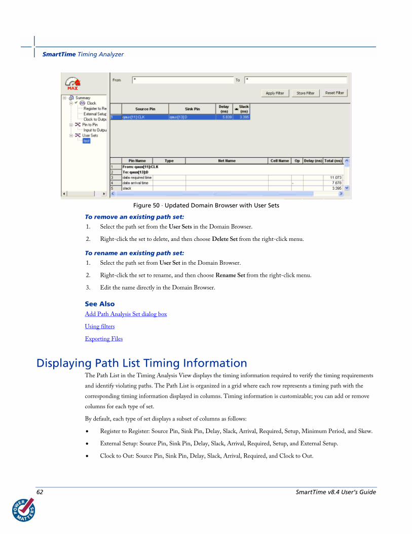
SmartTime Timing Analyzer
62 SmartTime v8.4 User’s Guide
Figure 50 · Updated Domain Browser with User Sets
To remove an existing path set:
1. Select the path set from the User Sets in the Domain Browser.
2. Right-click the set to delete, and then choose Delete Set from the right-click menu.
To rename an existing path set:
1. Select the path set from User Set in the Domain Browser.
2. Right-click the set to rename, and then choose Rename Set from the right-click menu.
3. Edit the name directly in the Domain Browser.
See Also Add Path Analysis Set dialog box
Using filters
Exporting Files
Displaying Path List Timing Information The Path List in the Timing Analysis View displays the timing information required to verify the timing requirements
and identify violating paths. The Path List is organized in a grid where each row represents a timing path with the
corresponding timing information displayed in columns. Timing information is customizable; you can add or remove
columns for each type of set.
By default, each type of set displays a subset of columns as follows:
• Register to Register: Source Pin, Sink Pin, Delay, Slack, Arrival, Required, Setup, Minimum Period, and Skew.
• External Setup: Source Pin, Sink Pin, Delay, Slack, Arrival, Required, Setup, and External Setup.
• Clock to Out: Source Pin, Sink Pin, Delay, Slack, Arrival, Required, and Clock to Out.
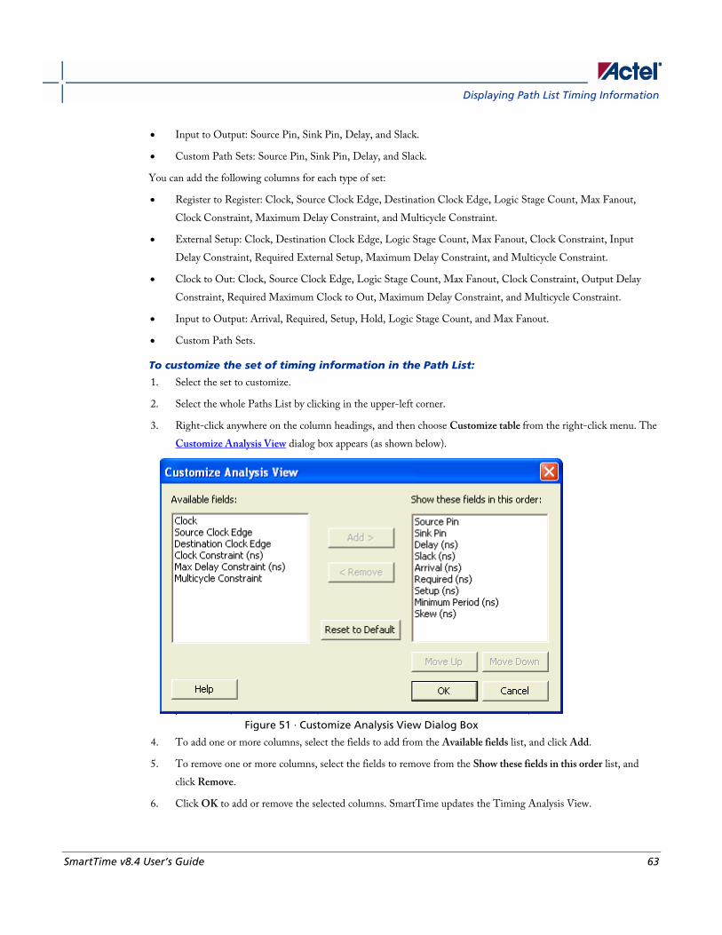
Displaying Path List Timing Information
SmartTime v8.4 User’s Guide 63
• Input to Output: Source Pin, Sink Pin, Delay, and Slack.
• Custom Path Sets: Source Pin, Sink Pin, Delay, and Slack.
You can add the following columns for each type of set:
• Register to Register: Clock, Source Clock Edge, Destination Clock Edge, Logic Stage Count, Max Fanout,
Clock Constraint, Maximum Delay Constraint, and Multicycle Constraint.
• External Setup: Clock, Destination Clock Edge, Logic Stage Count, Max Fanout, Clock Constraint, Input
Delay Constraint, Required External Setup, Maximum Delay Constraint, and Multicycle Constraint.
• Clock to Out: Clock, Source Clock Edge, Logic Stage Count, Max Fanout, Clock Constraint, Output Delay
Constraint, Required Maximum Clock to Out, Maximum Delay Constraint, and Multicycle Constraint.
• Input to Output: Arrival, Required, Setup, Hold, Logic Stage Count, and Max Fanout.
• Custom Path Sets.
To customize the set of timing information in the Path List:
1. Select the set to customize.
2. Select the whole Paths List by clicking in the upper-left corner.
3. Right-click anywhere on the column headings, and then choose Customize table from the right-click menu. The
Customize Analysis View dialog box appears (as shown below).
Figure 51 · Customize Analysis View Dialog Box
4. To add one or more columns, select the fields to add from the Available fields list, and click Add.
5. To remove one or more columns, select the fields to remove from the Show these fields in this order list, and
click Remove.
6. Click OK to add or remove the selected columns. SmartTime updates the Timing Analysis View.
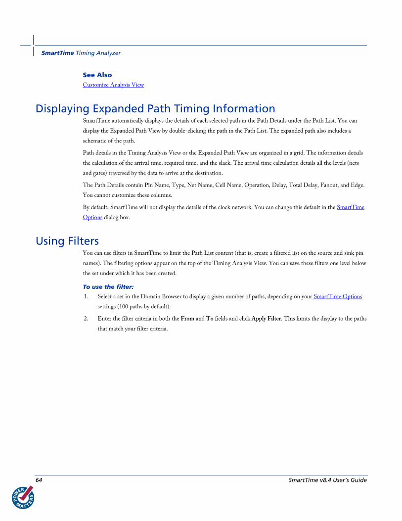
SmartTime Timing Analyzer
64 SmartTime v8.4 User’s Guide
See Also Customize Analysis View
Displaying Expanded Path Timing Information SmartTime automatically displays the details of each selected path in the Path Details under the Path List. You can
display the Expanded Path View by double-clicking the path in the Path List. The expanded path also includes a
schematic of the path.
Path details in the Timing Analysis View or the Expanded Path View are organized in a grid. The information details
the calculation of the arrival time, required time, and the slack. The arrival time calculation details all the levels (nets
and gates) traversed by the data to arrive at the destination.
The Path Details contain Pin Name, Type, Net Name, Cell Name, Operation, Delay, Total Delay, Fanout, and Edge.
You cannot customize these columns.
By default, SmartTime will not display the details of the clock network. You can change this default in the SmartTime
Options dialog box.
Using Filters You can use filters in SmartTime to limit the Path List content (that is, create a filtered list on the source and sink pin
names). The filtering options appear on the top of the Timing Analysis View. You can save these filters one level below
the set under which it has been created.
To use the filter:
1. Select a set in the Domain Browser to display a given number of paths, depending on your SmartTime Options
settings (100 paths by default).
2. Enter the filter criteria in both the From and To fields and click Apply Filter. This limits the display to the paths
that match your filter criteria.
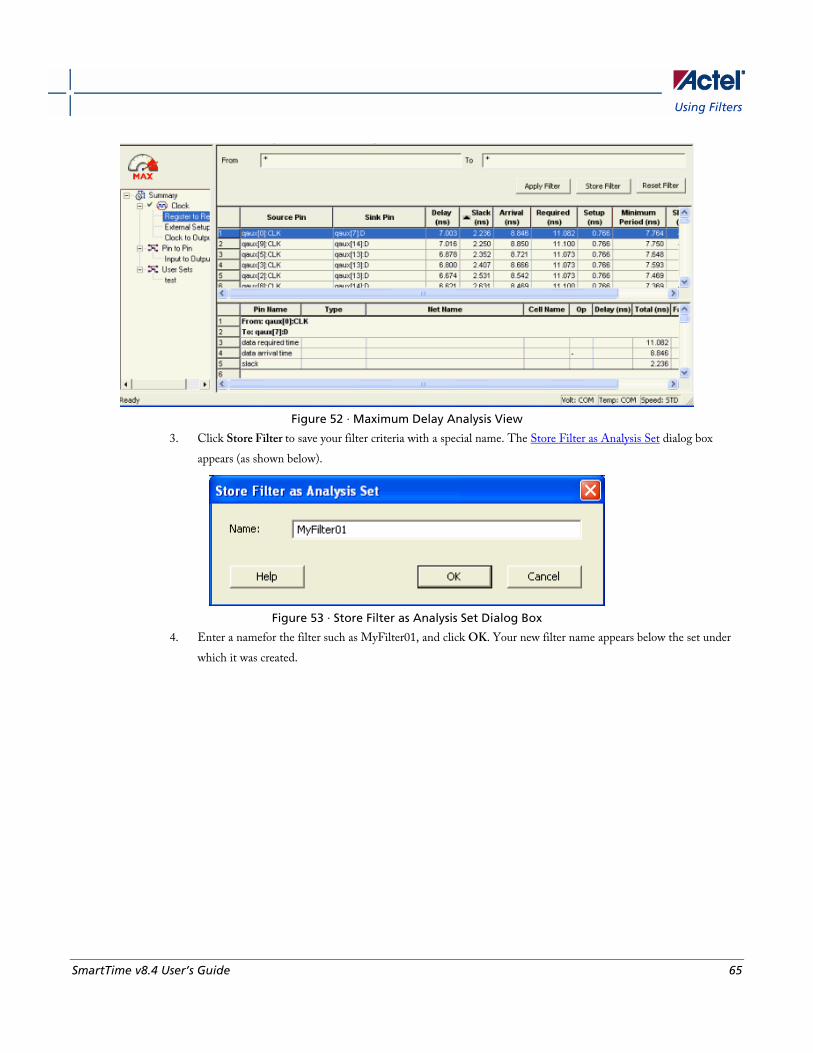
Using Filters
SmartTime v8.4 User’s Guide 65
Figure 52 · Maximum Delay Analysis View
3. Click Store Filter to save your filter criteria with a special name. The Store Filter as Analysis Set dialog box
appears (as shown below).
Figure 53 · Store Filter as Analysis Set Dialog Box
4. Enter a namefor the filter such as MyFilter01, and click OK. Your new filter name appears below the set under
which it was created.

SmartTime Timing Analyzer
66 SmartTime v8.4 User’s Guide
Figure 54 · Updated Maximum Delay Analysis View
Repeat the above steps and cascade as many sets as you need using the filtering mechanism.
To remove a set created with filters:
1. Select the set that uses filters.
2. Right-click the set, and choose Delete Set from the shortcut menu.
To rename a set created with filters:
1. Select the set that uses filters.
2. Right-click the set, and choose Rename Set from the shortcut menu.
3. Edit the name directly in the Domain Browser.
To edit a specific filter in the set:
1. Select the filter to edit.
2. Right-click the filter, and choose Edit Set from the shortcut menu.
See Also SmartTime Options
Store Filter as Analysis Set
Edit Set dialog box
Exporting Files

Cross-Probing between ChipPlanner and SmartTime
SmartTime v8.4 User’s Guide 67
Cross-Probing between ChipPlanner and SmartTime Use ChipPlanner with SmartTime to identify the signal path or individual instances in ChipPlanner.
To identify paths in ChipPlanner:
1. In the Design Flow window, click ChipPlanner to display the chip view, and then click Timing Analyzer to
display the SmartTime Timing Analyzer.
2. In the SmartTimeTiming Analyzer, select the clock domain in the Domain Browser.
3. Select a set in the Path list (as shown below) and the paths within that set are displayed in the Path Details
(lower table). The Paths List displays timing information for various categories.
Figure 55 · Path Details of Selected Path Highlighted
4. Select the path to cross-probe.
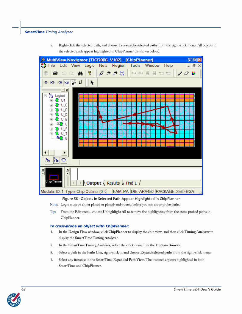
SmartTime Timing Analyzer
68 SmartTime v8.4 User’s Guide
5. Right-click the selected path, and choose Cross-probe selected paths from the right-click menu. All objects in
the selected path appear highlighted in ChipPlanner (as shown below).
Figure 56 · Objects in Selected Path Appear Highlighted in ChipPlanner
Note: Logic must be either placed or placed-and-routed before you can cross-probe paths.
Tip: From the Edit menu, choose Unhighlight All to remove the highlighting from the cross-probed paths in
ChipPlanner.
To cross-probe an object with ChipPlanner:
1. In the Design Flow window, click ChipPlanner to display the chip view, and then click Timing Analyzer to
display the SmartTime Timing Analyzer.
2. In the SmartTimeTiming Analyzer, select the clock domain in the Domain Browser.
3. Select a path in the Paths List, right-click it, and choose Expand selected paths from the right-click menu.
4. Select any instance in the SmartTime Expanded Path View. The instance appears highlighted in both
SmartTime and ChipPlanner.

Cross-Probing between ChipPlanner and SmartTime
SmartTime v8.4 User’s Guide 69
5. To cross-probe the path of the selected object, right-click the instance, and choose Cross-probe Path from the
right-click menu. All objects in the selected path appear highlighted in ChipPlanner.
When you cross-probe a path in ChipPlanner, the default view is the Ratsnest view, shown in the following example.
Figure 57 · Ratsnest view in ChipPlanner showing cross-probed path
Tip: To select multiple instances, hold down the Shift key as you click each instance.
The critical cross-probed path appears highlighted in ChipPlanner as a solid line with arrows indicating the direction
of the path. The color of the line is the color you selected for the highlight color.
You can right-click a selected cross-probed path, choose Properties to display the Path Properties dialog box, and do
one of the following:
• Rename the cross-probed path
• Assign a different color to the cross-probed path
You can create more than one cross-probed path in ChipPlanner, building one path on top of another. ChipPlanner
does not delete paths you have cross-probed. When you save your design, the cross-probed paths are also saved in your
design (.ADB) file.
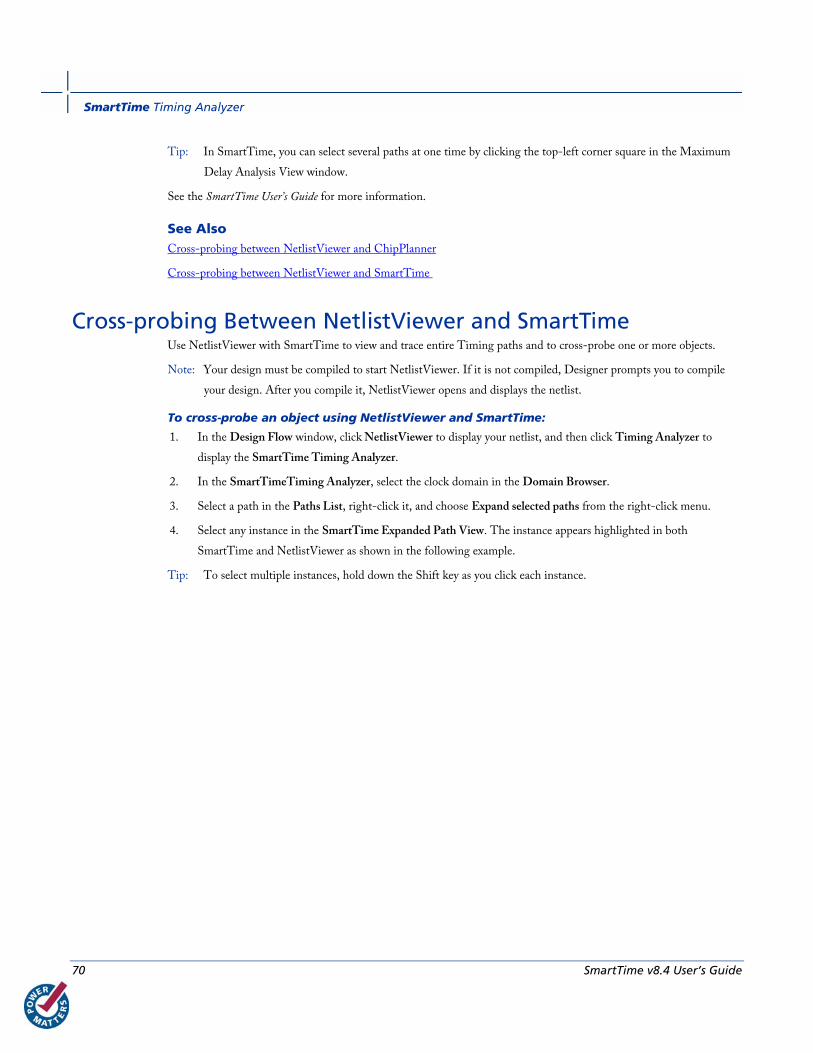
SmartTime Timing Analyzer
70 SmartTime v8.4 User’s Guide
Tip: In SmartTime, you can select several paths at one time by clicking the top-left corner square in the Maximum
Delay Analysis View window.
See the SmartTime User’s Guide for more information.
See Also Cross-probing between NetlistViewer and ChipPlanner
Cross-probing between NetlistViewer and SmartTime
Cross-probing Between NetlistViewer and SmartTime Use NetlistViewer with SmartTime to view and trace entire Timing paths and to cross-probe one or more objects.
Note: Your design must be compiled to start NetlistViewer. If it is not compiled, Designer prompts you to compile
your design. After you compile it, NetlistViewer opens and displays the netlist.
To cross-probe an object using NetlistViewer and SmartTime:
1. In the Design Flow window, click NetlistViewer to display your netlist, and then click Timing Analyzer to
display the SmartTime Timing Analyzer.
2. In the SmartTimeTiming Analyzer, select the clock domain in the Domain Browser.
3. Select a path in the Paths List, right-click it, and choose Expand selected paths from the right-click menu.
4. Select any instance in the SmartTime Expanded Path View. The instance appears highlighted in both
SmartTime and NetlistViewer as shown in the following example.
Tip: To select multiple instances, hold down the Shift key as you click each instance.

Cross-probing Between NetlistViewer and SmartTime
SmartTime v8.4 User’s Guide 71
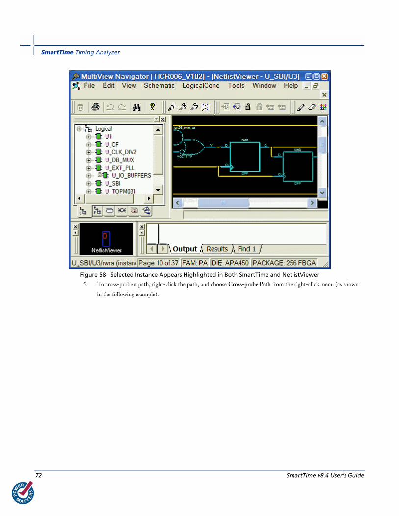
SmartTime Timing Analyzer
72 SmartTime v8.4 User’s Guide
Figure 58 · Selected Instance Appears Highlighted in Both SmartTime and NetlistViewer
5. To cross-probe a path, right-click the path, and choose Cross-probe Path from the right-click menu (as shown
in the following example).
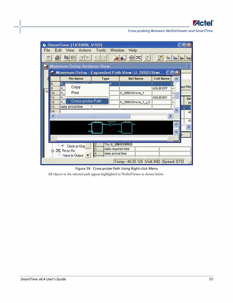
Cross-probing Between NetlistViewer and SmartTime
SmartTime v8.4 User’s Guide 73
Figure 59 · Cross-probe Path Using Right-click Menu
All objects in the selected path appear highlighted in NetlistViewer as shown below.

SmartTime Timing Analyzer
74 SmartTime v8.4 User’s Guide
Figure 60 · All Objects in the Cross-probed Path Appear Highlighted in NetlistViewer
Tip: Changing the highlight color does not change the color of all cross-probed paths in NetlistViewer. To change
the color of a cross-probed path, from the Edit menu, choose Highlight Color and select a different color.
Then cross-probe the path again in SmartTime. The cross-probed path will appear in the new highlight color.
See the SmartTime User’s Guide for more information.
See Also Identifying Paths
Cross-probing between NetlistViewer and ChipPlanner
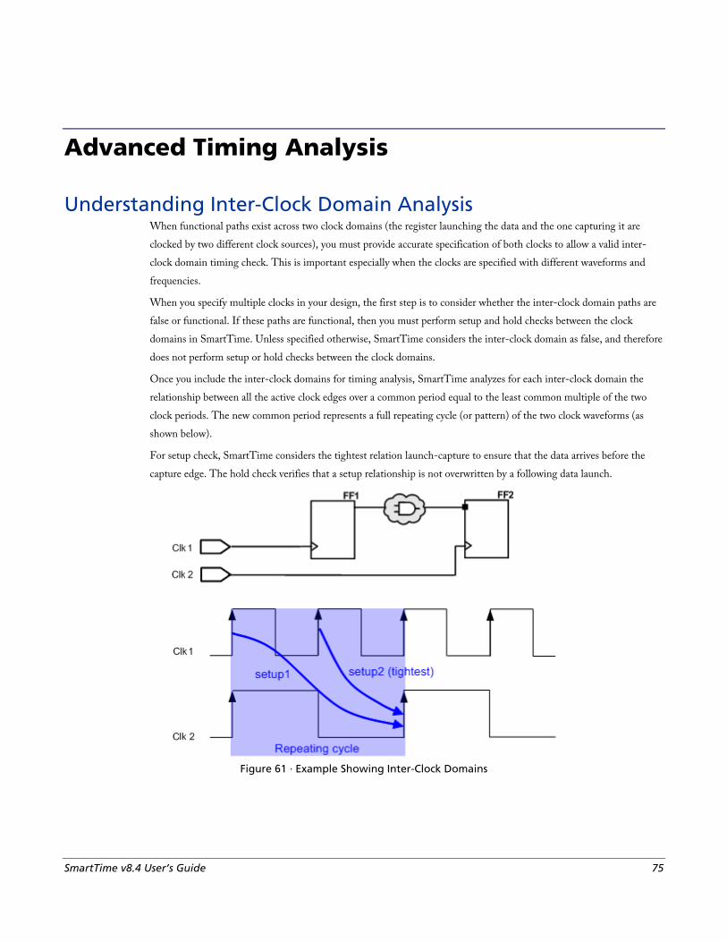
SmartTime v8.4 User’s Guide 75
Advanced Timing Analysis
Understanding Inter-Clock Domain Analysis When functional paths exist across two clock domains (the register launching the data and the one capturing it are
clocked by two different clock sources), you must provide accurate specification of both clocks to allow a valid inter-
clock domain timing check. This is important especially when the clocks are specified with different waveforms and
frequencies.
When you specify multiple clocks in your design, the first step is to consider whether the inter-clock domain paths are
false or functional. If these paths are functional, then you must perform setup and hold checks between the clock
domains in SmartTime. Unless specified otherwise, SmartTime considers the inter-clock domain as false, and therefore
does not perform setup or hold checks between the clock domains.
Once you include the inter-clock domains for timing analysis, SmartTime analyzes for each inter-clock domain the
relationship between all the active clock edges over a common period equal to the least common multiple of the two
clock periods. The new common period represents a full repeating cycle (or pattern) of the two clock waveforms (as
shown below).
For setup check, SmartTime considers the tightest relation launch-capture to ensure that the data arrives before the
capture edge. The hold check verifies that a setup relationship is not overwritten by a following data launch.
Figure 61 · Example Showing Inter-Clock Domains

Advanced Timing Analysis
76 SmartTime v8.4 User’s Guide
See Also Activating inter-clock domain analysis
Deactivating a specific inter-clock domain
Displaying inter-clock domain paths
Activating Inter-Clock Domain Analysis To activate the inter-clock domain checking:
1. In SmartTime, from the Tools menu choose Options. The SmartTime Options dialog box appears (as shown
below).
2. In the general category, check the Include inter-clock domains in calculations for timing analysis.
Figure 62 · SmartTime Options Dialog Box
3. Click OK to save the dialog box settings.
See Also Understanding inter-clock domain analysis
Deactivating a specific inter-clock domain
Displaying inter-clock domain paths
SmartTime Options dialog box
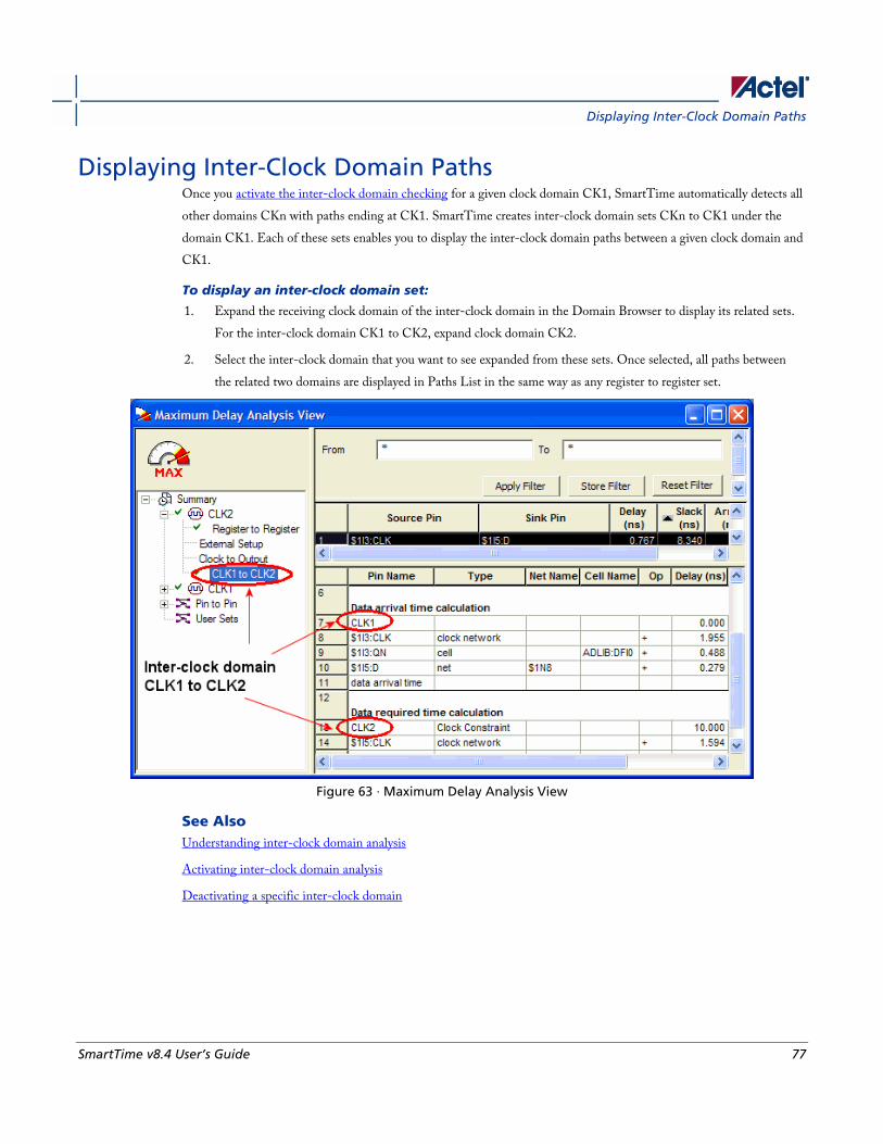
Displaying Inter-Clock Domain Paths
SmartTime v8.4 User’s Guide 77
Displaying Inter-Clock Domain Paths Once you activate the inter-clock domain checking for a given clock domain CK1, SmartTime automatically detects all
other domains CKn with paths ending at CK1. SmartTime creates inter-clock domain sets CKn to CK1 under the
domain CK1. Each of these sets enables you to display the inter-clock domain paths between a given clock domain and
CK1.
To display an inter-clock domain set:
1. Expand the receiving clock domain of the inter-clock domain in the Domain Browser to display its related sets.
For the inter-clock domain CK1 to CK2, expand clock domain CK2.
2. Select the inter-clock domain that you want to see expanded from these sets. Once selected, all paths between
the related two domains are displayed in Paths List in the same way as any register to register set.
Figure 63 · Maximum Delay Analysis View
See Also Understanding inter-clock domain analysis
Activating inter-clock domain analysis
Deactivating a specific inter-clock domain

Advanced Timing Analysis
78 SmartTime v8.4 User’s Guide
Deactivating a Specific Inter-Clock Domain To deactivate the inter-clock domain checking for the specific clock domains clk1->clk2, without disabling this option for the other clock domains:
1. From the Tools menu, choose Constraints Editor > Primary Scenario to open the Constraints Editor View.
2. In the Constraints Browser, double-click False Path under Exceptions. The "Set False Path Constraint dialog
box appears.
3. Click the Browse button to the right of the From text box. The Select Source Pins for False Path Constraint
dialog box appears.
4. For Specify pins, select by keyword and wildcard.
5. For Pin Type, select Registers by clock names from the Pin Type drop-down list.
6. Type the inter-clock domain name, for example Clk1 in the filter box and click Filter.
7. Click OK to begin filtering the pins by your criteria. In this example, [get_clocks {Clk1}] appears in the From
text box in the Set False Path Constraint dialog box.
8. Repeat steps 3 to 7 for the To option in the Set False Path Constraint dialog box, and type Clk2 in the filter box.
9. Click OK to validate the new false path and display it in the Paths List of the Constraints Editor.
10. Click the Recalculate All icon in the toolbar.
11. Select the inter-clock domain set clk1 -> clk2 in the Domain Browser (as shown below).
12. Verify that the set does not contain any paths.

Timing Exceptions Overview
SmartTime v8.4 User’s Guide 79
Figure 64 · Maximum Delay Analysis View
See Also Understanding inter-clock domain analysis
Activating inter-clock domain analysis
Displaying inter-clock domain paths
Select Source or Destination Pins for Constraint dialog box
Set False Path Constraint dialog box
Timing Exceptions Overview Use timing exceptions to overwrite the default behavior of the design path. Timing exceptions include:
• Setting multicycle constraint to specify paths that (by design) will take more than one cycle.
• Setting a false path constraint to identify paths that must not be included in the timing analysis or the
optimization flow.
• Setting a maximum delay constraint on specific paths to relax or to tighten the original clock constraint
requirement.

Advanced Timing Analysis
80 SmartTime v8.4 User’s Guide
See Also Specifying maximum delay constraint
Specifying multiple path constraint
Specifying false path constraint
Changing output port capacitance
Specifying a Maximum Delay Constraint You set options in the Maximum Delay Constraint dialog box to relax or to tighten the original clock constraint
requirement on specific paths.
To specify Max delay constraints:
1. Add the constraint in the editable constraints grid or open the Set Maximum Delay Constraint dialog box using
one of the following methods:
• From the SmartTime Actions menu, choose Constraints > Max delay.
• Click the icon.
• Right-click Max delay in the Constraint Browser.
• Double-click any field in the Maximum Delay Constraints grid.
The Set Maximum Delay Constraint dialog box appears (as shown below).
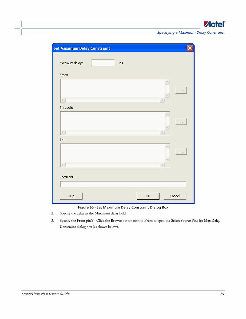
Specifying a Maximum Delay Constraint
SmartTime v8.4 User’s Guide 81
Figure 65 · Set Maximum Delay Constraint Dialog Box
2. Specify the delay in the Maximum delay field.
3. Specify the From pin(s). Click the Browse button next to From to open the Select Source Pins for Max Delay
Constraint dialog box (as shown below).
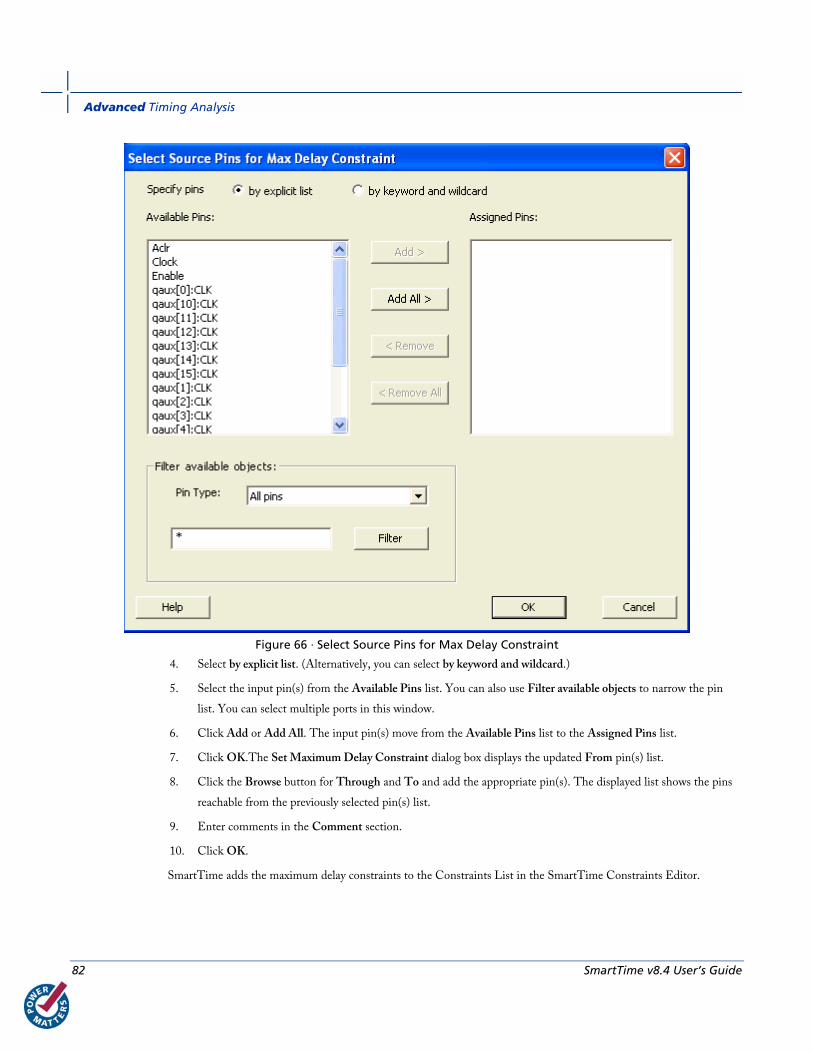
Advanced Timing Analysis
82 SmartTime v8.4 User’s Guide
Figure 66 · Select Source Pins for Max Delay Constraint
4. Select by explicit list. (Alternatively, you can select by keyword and wildcard.)
5. Select the input pin(s) from the Available Pins list. You can also use Filter available objects to narrow the pin
list. You can select multiple ports in this window.
6. Click Add or Add All. The input pin(s) move from the Available Pins list to the Assigned Pins list.
7. Click OK.The Set Maximum Delay Constraint dialog box displays the updated From pin(s) list.
8. Click the Browse button for Through and To and add the appropriate pin(s). The displayed list shows the pins
reachable from the previously selected pin(s) list.
9. Enter comments in the Comment section.
10. Click OK.
SmartTime adds the maximum delay constraints to the Constraints List in the SmartTime Constraints Editor.
Specifying a Minimum Delay Constraint
SmartTime v8.4 User’s Guide 83
See Also Timing exceptions overview
Set Maximum Delay Constraint dialog box
Specifying maximum delay constraint
Specifying multicycle constraint
Specifying false path constraint
Changing output port capacitance
Specifying a Minimum Delay Constraint You set options in the Minimum Delay Constraint dialog box to relax or to tighten the original clock constraint
requirement on specific paths.
To specify Min delay constraints:
1. Add the constraint in the editable constraints grid or open the Set Minimum Delay Constraint dialog box using
one of the following methods:
• From the SmartTime Actions menu, choose Constraints > Min delay.
• Click the icon.
• Right-click Min delay in the Constraint Browser.
• Double-click any field in the Minimum Delay Constraints grid.
The Set Minimum Delay Constraint dialog box appears (as shown below).
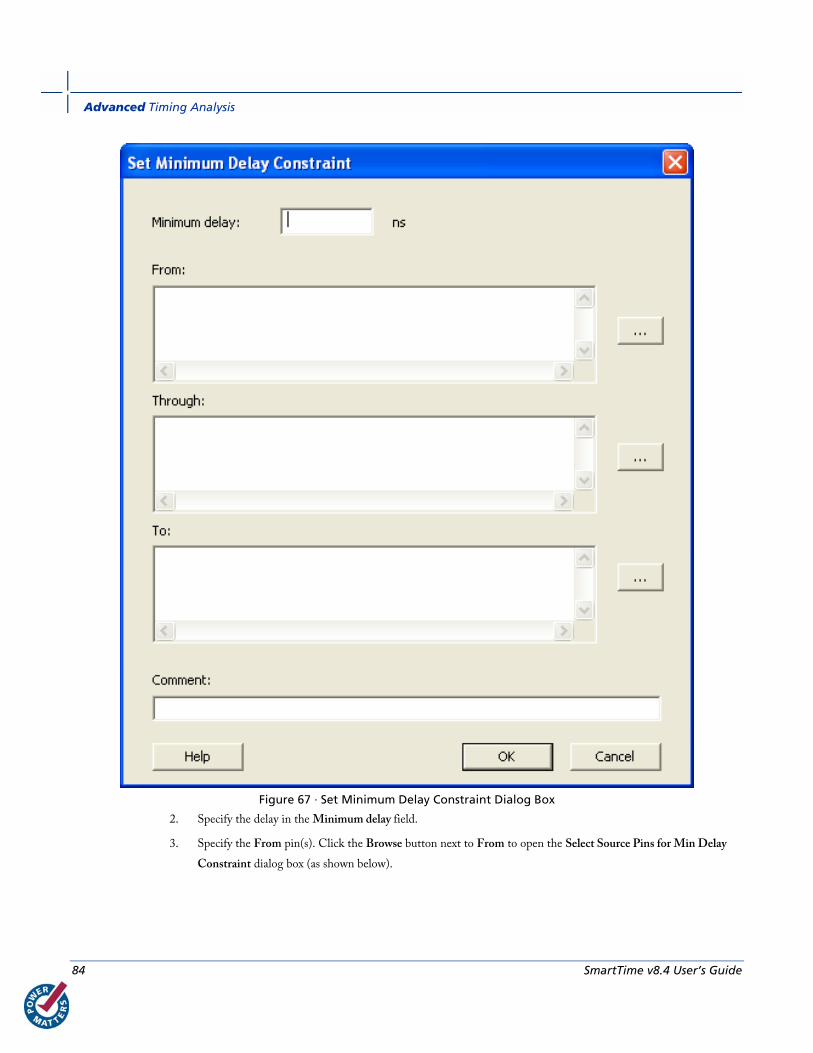
Advanced Timing Analysis
84 SmartTime v8.4 User’s Guide
Figure 67 · Set Minimum Delay Constraint Dialog Box
2. Specify the delay in the Minimum delay field.
3. Specify the From pin(s). Click the Browse button next to From to open the Select Source Pins for Min Delay
Constraint dialog box (as shown below).
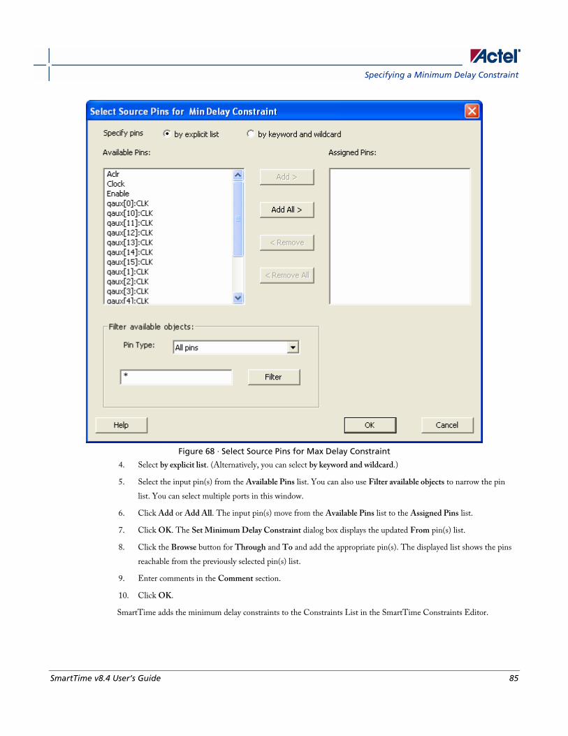
Specifying a Minimum Delay Constraint
SmartTime v8.4 User’s Guide 85
Figure 68 · Select Source Pins for Max Delay Constraint
4. Select by explicit list. (Alternatively, you can select by keyword and wildcard.)
5. Select the input pin(s) from the Available Pins list. You can also use Filter available objects to narrow the pin
list. You can select multiple ports in this window.
6. Click Add or Add All. The input pin(s) move from the Available Pins list to the Assigned Pins list.
7. Click OK. The Set Minimum Delay Constraint dialog box displays the updated From pin(s) list.
8. Click the Browse button for Through and To and add the appropriate pin(s). The displayed list shows the pins
reachable from the previously selected pin(s) list.
9. Enter comments in the Comment section.
10. Click OK.
SmartTime adds the minimum delay constraints to the Constraints List in the SmartTime Constraints Editor.
Advanced Timing Analysis
86 SmartTime v8.4 User’s Guide
See Also Timing exceptions overview
Set Minimum Delay Constraint dialog box
Specifying multicycle constraint
Specifying false path constraint
Changing output port capacitance
Specifying a Multicycle Constraint You set options in the Set Multicycle Constraint dialog box to specify paths that take multiple clock cycles in the
current design.
To specify multicycle constraints:
1. Add the constraint in the editable constraints grid or open the Set Multicycle Constraint dialog box using one of
the following methods:
• From the SmartTime Actions menu, choose Constraint > MultiCycle.
• Click the icon.
• Right-click the Multicycle option in the Constraint Browser.
The Set Multicycle Constraint dialog appears (as shown below).
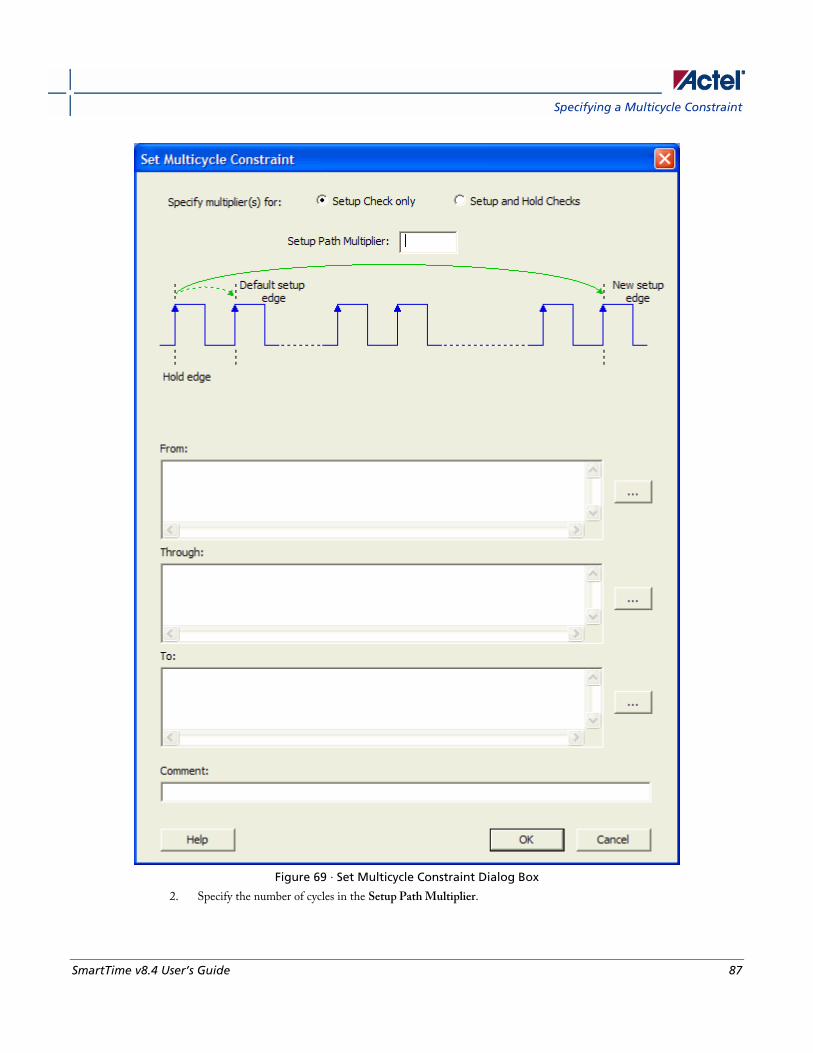
Specifying a Multicycle Constraint
SmartTime v8.4 User’s Guide 87
Figure 69 · Set Multicycle Constraint Dialog Box
2. Specify the number of cycles in the Setup Path Multiplier.

Advanced Timing Analysis
88 SmartTime v8.4 User’s Guide
3. Specify the From pin(s). Click the browse button (...) next to From to open the Select Source Pins for
Multicycle Constraint dialog box (as shown below).
Figure 70 · Select Source Pins for Multicycle Constraint
4. Select by explicit list. (Alternatively, you can select by keyword and wildcard. For details, refer to Select Source or
Destination Pins for Constraint.)
5. Select the input pin(s) from the Available Pin list. You can use Filter available objects to narrow the pin list. You
can select multiple ports in this window.
6. Click Add or Add All to move theinput pin(s) move from the Available pins list to the Assigned Pins list.
7. Click OK.
The Set Multicycle Constraint dialog box displays the updated representation of the From pin(s) (as shown below).
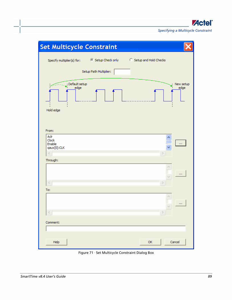
Specifying a Multicycle Constraint
SmartTime v8.4 User’s Guide 89
Figure 71 · Set Multicycle Constraint Dialog Box
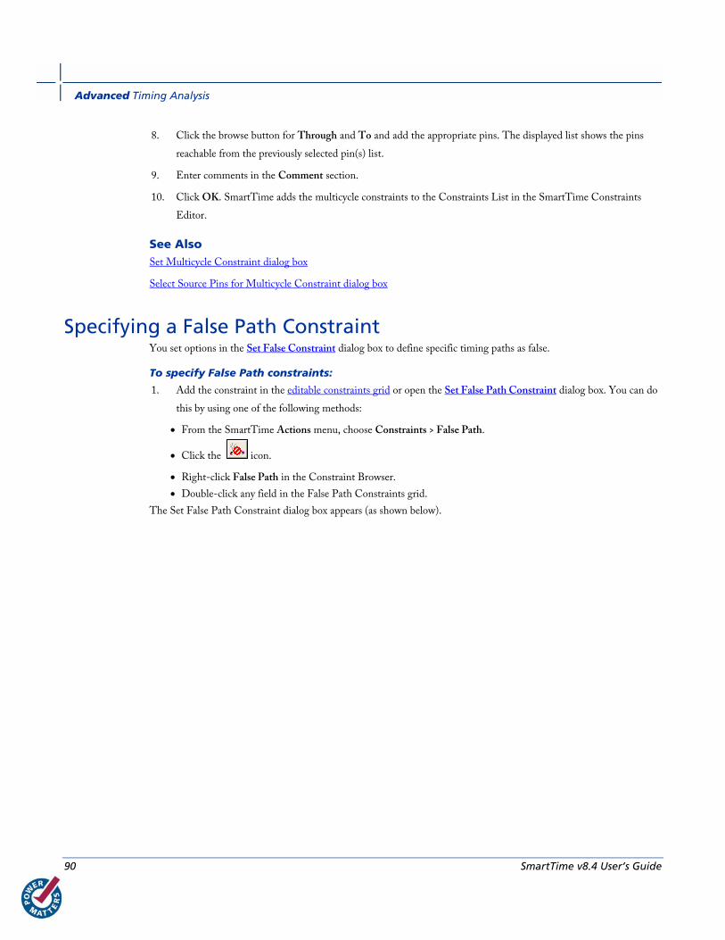
Advanced Timing Analysis
90 SmartTime v8.4 User’s Guide
8. Click the browse button for Through and To and add the appropriate pins. The displayed list shows the pins
reachable from the previously selected pin(s) list.
9. Enter comments in the Comment section.
10. Click OK. SmartTime adds the multicycle constraints to the Constraints List in the SmartTime Constraints
Editor.
See Also Set Multicycle Constraint dialog box
Select Source Pins for Multicycle Constraint dialog box
Specifying a False Path Constraint You set options in the Set False Constraint dialog box to define specific timing paths as false.
To specify False Path constraints:
1. Add the constraint in the editable constraints grid or open the Set False Path Constraint dialog box. You can do
this by using one of the following methods:
• From the SmartTime Actions menu, choose Constraints > False Path.
• Click the icon.
• Right-click False Path in the Constraint Browser.
• Double-click any field in the False Path Constraints grid.
The Set False Path Constraint dialog box appears (as shown below).
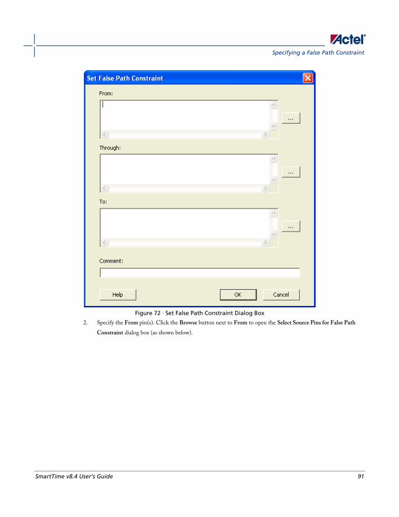
Specifying a False Path Constraint
SmartTime v8.4 User’s Guide 91
Figure 72 · Set False Path Constraint Dialog Box
2. Specify the From pin(s). Click the Browse button next to From to open the Select Source Pins for False Path
Constraint dialog box (as shown below).

Advanced Timing Analysis
92 SmartTime v8.4 User’s Guide
Figure 73 · Select Source Pins for False Path Constraint Dialog Box
3. Select by explicit list. (Alternatively, you can select by keyword and wildcard. For details, refer to Select Source or
Destination Pins for Constraint.)
4. Select the input pin(s) from the Available Pin list. You can use Filter available objects to narrow the pin list. You
can select multiple ports in this window.
5. Click Add or Add All. The input pin(s) move from the Available Pins list to the Assigned Pins list.
6. Click OK.
The Set False Constraint dialog box displays the updated representation of the From pin(s).
7. Click the Browse button for Through and To and add the appropriate pin(s). The displayed list shows the pins
reachable from the previously selected pin(s) list.
8. Enter comments in the Comment section.
9. Click OK.
SmartTime adds the False Path constraints to the Constraints List in the SmartTime Constraints Editor.

Changing Output Port Capacitance
SmartTime v8.4 User’s Guide 93
See Also Set False Constraint dialog box
Select Source Pins for False Path Constraint dialog box.
Changing Output Port Capacitance Output propagation delay is affected by both the capacitive loading on the board and the I/O standard. The I/O
Attribute Editor in ChipPlanner (PinEditor in the SX-A family) provides a mechanism for setting the expected
capacitance to improve the propagation delay model. SmartTime automatically uses the modified delay model for delay
calculations.
To change the output port capacitance and view the effect of this change in SmartTime Timing Analyzer, refer to the
following example. The figure below shows the delay from FF3 to output port OUT2. It shows a delay of 6.603 ns
based on the default loading of 35 pF.
Figure 74 · Maximum Delay Analysis View
If your board has output capacitance of 75pf on OUT2, you must perform the following steps to update the timing
number:
1. Open the I/O Attribute Editor and change the output load to 75pf.

Advanced Timing Analysis
94 SmartTime v8.4 User’s Guide
Figure 75 · I/O Attribute Editor View
2. Select File > Commit.
3. Select File > Close.
4. Open the SmartTime Timing Analyzer.
You can see that the Clock to Output delay changed to 7.723 ns.
Specifying Clock Source Latency Use clock source latency to specify the delay from the clock generation point to the clock definition point in the design.
Clock source latency defines the delay between an external clock source and the definition pin of a clock within
SmartTime. It behaves much like an input delay constraint.
You can specify both an "early" delay and a "late" delay for this latency, providing an uncertainty which SmartTime
propagates through its calculations. Rising and falling edges of the same clock can have different latencies. If only one
value is provided for the clock source latency, it is taken as the exact latency value, for both rising and falling edges.
To specify the clock source latency:
1. Add the constraint in the editable constraints grid or open the Set Clock Source Latency dialog box using one of
the following methods:
• From the SmartTime Actions menu, choose Constraints > Clock Source Latency.
• Click the icon.
• Right-click Clock Source Latency in the Constraint Browser.
• Double-click any field in the Clock Source Latency grid.
2. Select a clock pin on which to set the source latency. You can only specify a clock source latency on a clock pin
that has a clock constraint. Additionally, you may apply only one clock source latency constraint to each
constrained clock pin.
3. Enter the Late Rise, Early Rise, Late Fall, and Early Fall values as required for your design.
Note: an ‘early’ value larger than a ‘late’ value can result in optimistic timing analysis.
4. Select the Falling Same As Rising check box to indicate that falling clock edges have the same latency as rising
clock edges.
5. Select the Early Same As Late check box to use a single value for the clock latency, rather than a range, by
clicking the checkbox.

Specifying Disable Timing Constraint
SmartTime v8.4 User’s Guide 95
6. Enter any comments to be attached to the constraint.
7. Click OK. The new constraint appears in the constraints list.
Note: When you choose Commit from the File menu, SmartTime saves the newly-created constraint in the
database.
See Also Set Clock Source Latency dialog box
Specifying Disable Timing Constraint Use disable timing constraint to specify the timing arcs being disabled.
To specify the disable timing constraint:
1. Add the constraint in the editable constraints grid or open the Set Constraint to Disable Timing Arcs dialog box
using one of the following methods:
• From the SmartTime Actions menu, choose Constraints > Disable Timing.
• Click the icon.
• Right-click Disable Timing in the Constraint Browser.
• Double-click any field in the Disable Timing grid.
2. Select an instance from your design.
3. Select whether you want to exclude all timing arcs in the instance or if you want to specify the timing arc to
exclude. If you selected specify timing arc to exclude, select a from and to port for the timing arc.
4. Enter any comments to be attached to the constraint.
5. Click OK. The new constraint appears in the constraints list.
Note: When you choose Commit from the File menu, SmartTime saves the newly-created constraint in the
database.
See Also Set Constraint to Disable Timing Arcs Dialog Box


SmartTime v8.4 User’s Guide 97
Generating Timing Reports
Types of Reports Using SmartTime you can generate the following types of reports:
• Timing report – This report displays the timing information organized by clock domain.
• Timing violations report – This flat slack report provides information about constraint violations.
• Datasheet report – This report describes the characteristics of the pins, I/O technologies, and timing properties
in the design.
• Bottleneck report – This report displays the points in the design that contribute to the most timing violations.
• Constraints coverage report – This report displays the overall coverage of the timing constraints set on the
current design.
• Combinational loop report – This report displays loops found during initialization.
See Also Generating timing report
Generating timing violation report
Generating a datasheet report
Generating a bottleneck report
Generating a constraints coverage report
Generating a Combinational Loop Report
Generating a Timing Report The timing report enables you to quickly determine if any timing problems exist in your design. The timing report lists
the following information about your design:
• Maximum delay from input I/O to output I/O
• Maximum delay from input I/O to internal registers
• Maximum delay from internal registers to output I/O
• Maximum delays for each clock network
• Maximum delays for interactions between clock networks
To generate a timing report:
1. From the Designer Tools menu, choose Reports > Timing > Timer. The Timing Report Options dialog box
appears.
2. Select the options you want to include in the report, and then click OK.
Generating Timing Reports
98 SmartTime v8.4 User’s Guide
The timing report appears in a separate window.
You can also generate the timing report from within SmartTime. From the Tools menu, choose Reports > Report
Paths.
See Also Understanding timing report
Timing Report Options dialog box
Understanding Timing Reports The timing report contains the following sections:
Header The header lists:
• The report type
• The version of Designer used to generate the report
• The date and time the report was generated
• General design information (name, family, etc.)
Summary The summary section reports the timing information for each clock domain.
By default, the clock domains reported are the explicit clock domains that are shown in SmartTime. You can filter the
domains and get only specific sections in the report (see Timing Report Options).
Path Sections The paths section lists the timing information for different types of paths in the design. This section is reported by
default. You can deselect this option in the Timing Report Options dialog box.
By default, the number of paths displayed per set is 5.
You can filter the domains using the Timing Report Options dialog box.
You can also view the stored filter sets in the generated report using the timing report options (see Timing Report
Options). The filter sets are listed by name in their appropriate section, and the number of paths reported for the filter
set is the same as for the main sets.
By default, the filter sets are not reported.
Clock domains The paths are organized by clock domain.
Understanding Timing Reports
SmartTime v8.4 User’s Guide 99
Register to Register set This set reports the paths from the registers clock pins to the registers data pins in the current clock domain.
Input to register set This set reports the paths from the top level design input ports to the registers in the current clock domain.
Register to output set This set reports the paths from the registers clock pins to the top level design output ports in the current clock domain.
Inter-clock domain This set reports the paths from the registers clock pins of the specified clock domain to the registers data pins in the
current clock domain. Inter-domain paths are not reported by default.
Pin to pin This set lists input to output paths and user sets. Input to output paths are reported by default. To see the user-defined
sets, use the Timing Report Options dialog box.
Input to output set This set reports the paths from the top level design input ports to top level design output ports.
Expanded Paths Expanded paths can be reported for each set. By default, the number of expanded paths to report is set to 1. You can
select and change the number when you specify Timing Report Options.
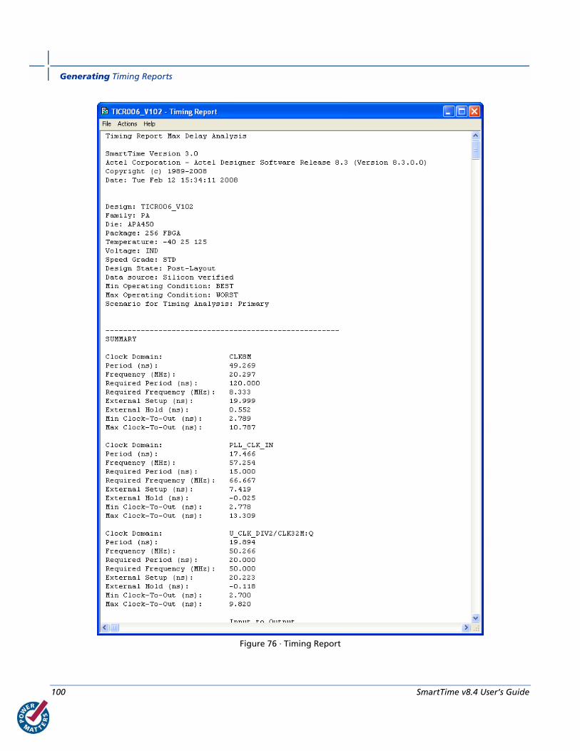
Generating Timing Reports
100 SmartTime v8.4 User’s Guide
Figure 76 · Timing Report
Generating a Timing Violation Report
SmartTime v8.4 User’s Guide 101
See Also Generating timing report
Timing Report Options dialog box
Generating a Timing Violation Report The timing violations report provides a flat slack report centered around constraint violations.
To generate a timing violation report
1. From the Designer Tools menu, choose Reports > Timing > Timing Violations. The Timing Violation Report
Options dialog box appears.
2. Select the options you want to include in the report, and then click OK. The timing violations report appears in a
separate window.
You can also generate the timing violations report from within SmartTime. From the Tools menu, choose Reports >
Report Violations.
See Also Understanding timing violation report
Timing Violations Report Options dialog box
Understanding Timing Violation Reports The timing violation report contains the following sections:
Header The header lists:
• The report type
• The version of Designer used to generate the report
• The date and time the report was generated
• General design information (name, family, etc.)
Paths The paths section lists the timing information for the violated paths in the design.
The number of paths displayed is controlled by two parameters:
• A maximum slack threshold to report
• A maximum number or path to report
By default, the slack threshold is 0 and the number of paths is limited. The default maximum number of paths reported
is 100.
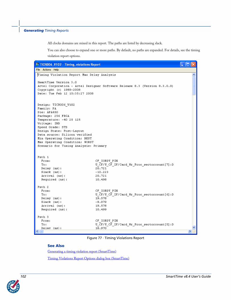
Generating Timing Reports
102 SmartTime v8.4 User’s Guide
All clocks domains are mixed in this report. The paths are listed by decreasing slack.
You can also choose to expand one or more paths. By default, no paths are expanded. For details, see the timing
violation report options.
Figure 77 · Timing Violations Report
See Also Generating a timing violation report (SmartTime)
Timing Violations Report Options dialog box (SmartTime)
Generating a Constraints Coverage Report
SmartTime v8.4 User’s Guide 103
Generating a Constraints Coverage Report The constraints coverage report contains information about the constraints in the design.
To generate a constraints coverage report, from the Designer Tools menu, select Reports > Timing > Constraints
Coverage. The report appears in a separate window.
You can also generate the constraints coverage report from within SmartTime. From the Tools menu, choose Reports
> Constraints Coverage.
See Also Understanding constraints coverage reports
Understanding Constraints Coverage Reports The constraint coverage displays the overall coverage of the timing constraints set on the current design. You can
generate this report either from within Designer or within SmartTime Analyzer. The report contains two sections:
• Coverage Summary
• Enhancement Suggestions
• Results by Clock Domain
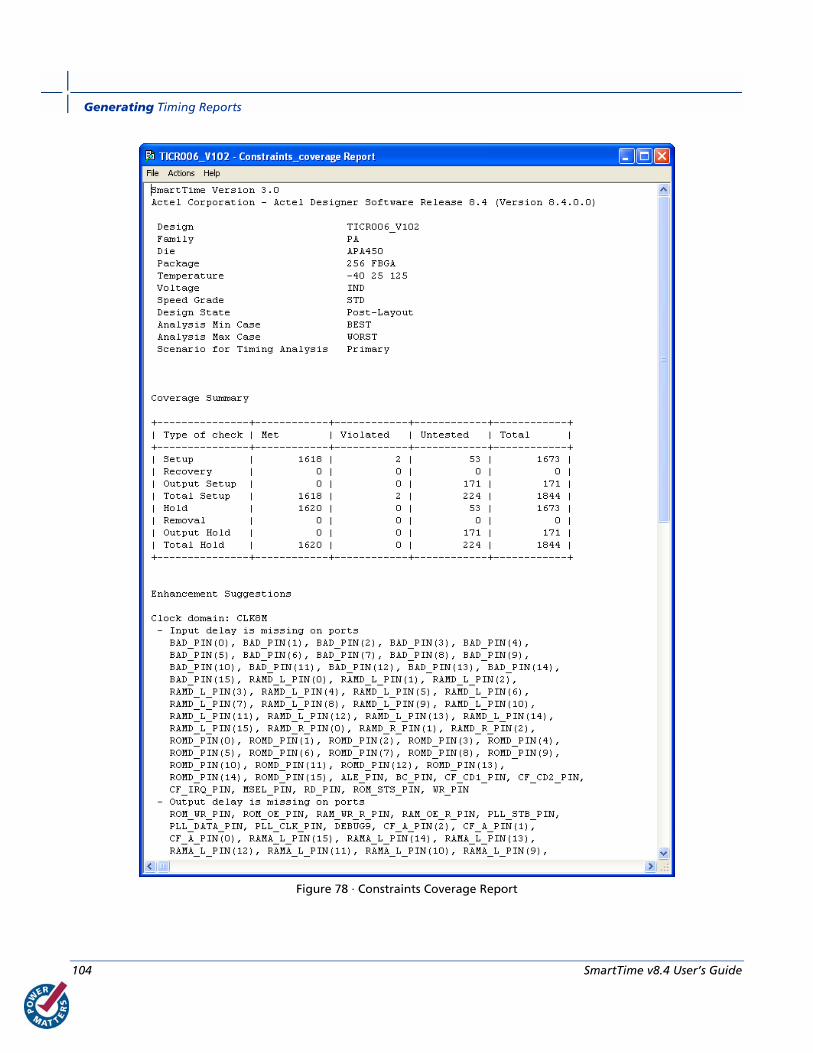
Generating Timing Reports
104 SmartTime v8.4 User’s Guide
Figure 78 · Constraints Coverage Report
Generating a Bottleneck Report
SmartTime v8.4 User’s Guide 105
Coverage Summary The coverage summary gives statistical information on the timing constraint in the design. For each type of timing
checks (Setup, Recovery, Output, Hold and Removal), it specifies how many are met (there is a constraint and it is
satisfied), violated (there is a constraint and it is not satisfied), or untested (no constraint was found).
Clock Domain This section provides a coverage summary for each clock domain.
Enhancement Suggestions The enhancement suggestion reports, per clock domain, a list of constraints that can be added to the design to improve
the coverage. It also reports if some options impacting the coverage can be changed.
Detailed Stats This section provides detailed suggestions regarding specific clocks or I/O ports that may require to be constrained for
every pin/port that requires checks.
See Also Clock
Input delay
Output delay
Setting SmartTime Options
Generating a Bottleneck Report The bottleneck report provides a list of the bottlenecks in the design.
To generate a bottleneck report, from the Designer Tools menu, select Reports > Timing > Bottleneck. The report
appears in a separate window.
You can also generate the bottleneck report from within SmartTime. From the Tools menu, choose Reports > Report
Bottlenecks.
See Also Understanding the bottleneck report
Timing Bottleneck Report Options dialog box

Generating Timing Reports
106 SmartTime v8.4 User’s Guide
Understanding Bottleneck Reports A bottleneck is a point in the design that contributes to multiple timing violations. The purpose of the bottleneck
report is to provide a list of the bottlenecks in the design. You can generate this report either from within Designer or
within SmartTime Analyzer. It contains two sections
• Device Description
• Bottleneck Description
Figure 79 · Bottleneck Report
Generating a Datasheet Report
SmartTime v8.4 User’s Guide 107
The bottleneck can only be computed if and only a cost type is defined. There are two options available:
• Path count: This cost type associates the severity of the bottleneck to the count of violating/critical paths that
traverse the instance.
• Path cost: This cost type associates the severity of the bottleneck to the sum of the timing violations for the
violating/critical paths that traverse the instance.
Device Description The device section contains general information about the design, including:
• Design name
• Family
• Die
• Package
• Software version
Bottleneck Description This section lists the core of the bottleneck information. It is divided into two columns:
• Instance name: refers to the output pin name of the instance.
• Bottleneck cost: displays the pin's cost given the chosen cost type. Pin names are listed in decreasing order of
their cost type.
See Also Generating a bottleneck report
Timing Bottleneck Report Options dialog box
Generating a Datasheet Report The datasheet reports information about the external characteristics of the design.
To generate a datasheet report, from the Designer Tools menu, select Reports > Timing > Datasheet. The report
appears in a separate window.
You can also generate the datasheet report from within SmartTime. From the Tools menu, choose Reports >
Datasheet.
See Also Understanding the datasheet report
Timing Datasheet Report Options dialog box
Generating Timing Reports
108 SmartTime v8.4 User’s Guide
Understanding Datasheet Reports The datasheet report displays the external characteristics of the design. You can generate this report either from within
Designer or within SmartTime Analyzer. It contains three tables:
• Pin Description
• DC Electrical Characteristics
• AC Electrical Characteristics
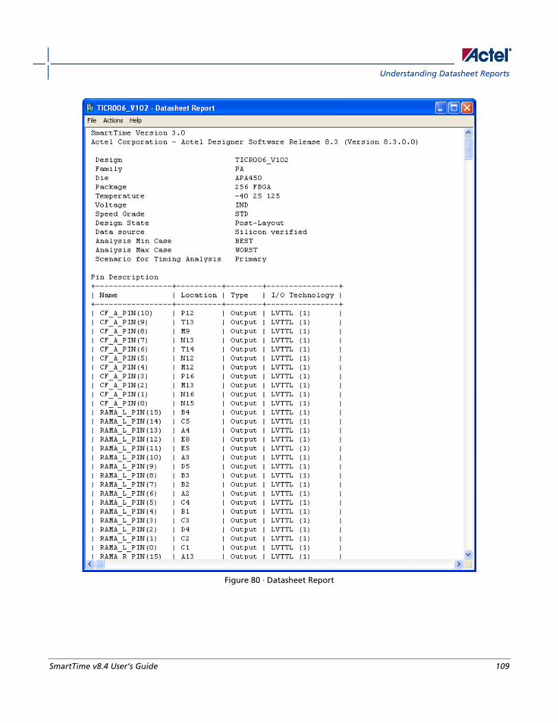
Understanding Datasheet Reports
SmartTime v8.4 User’s Guide 109
Figure 80 · Datasheet Report
Generating Timing Reports
110 SmartTime v8.4 User’s Guide
Pin Description Provides the port name in the netlist, location on the package, type of port, and I/O technology assigned to it. Types
can be input, output, inout, or clock. Clock ports are ports shown as "clock" in the Clock domain browser.
DC Electrical Characteristics Provides the parameters of the different I/O technologies used in the design. The number of parameters displayed
depends on the family for which you have created the design.
AC Electrical Characteristics Provides the timing properties of the ports of the design. For each clock, this section includes the maximum frequency.
For each input, it includes the external setup, external hold, external recovery, and external removal for every clock
where it applies. For each output, it includes the clock-to-out propagation time. This section also displays the input-to-
output propagation time for combinational paths.
See Also Generating a datasheet report
Timing Datasheet Report Options dialog box
Generating a Combinational Loop Report The combinational loop report displays all loops found during initialization and reports pins associated with the
loop(s), and the location where the loop is broken.
To generate a combinational loop report, from the Designer Tools menu, select Reports > Timing > Combinational
Loop. The report appears in a separate window.
You can also generate the combinational loop report from within SmartTime. From the Tools menu, choose Reports >
Combinational Loop.
See Also Understanding Combinational Loop Reports
Understanding Combinational Loop Reports The combinational loop report displays all loops found during initialization and reports pins associated with the
loop(s), and the location where the loop is broken.
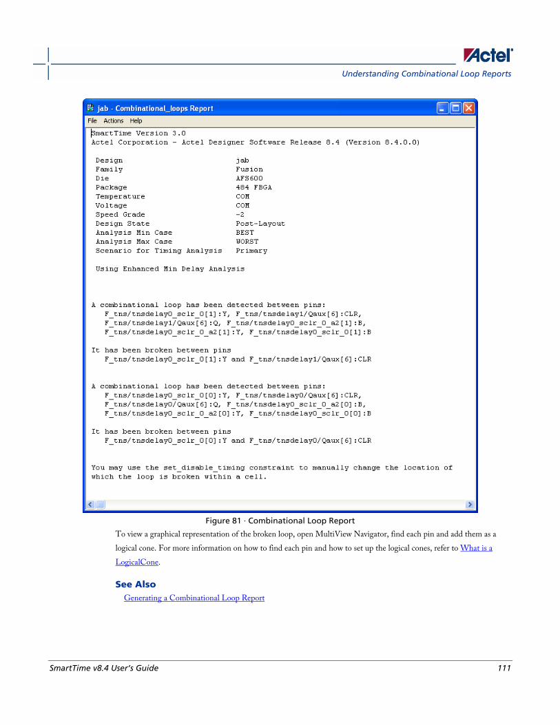
Understanding Combinational Loop Reports
SmartTime v8.4 User’s Guide 111
Figure 81 · Combinational Loop Report
To view a graphical representation of the broken loop, open MultiView Navigator, find each pin and add them as a
logical cone. For more information on how to find each pin and how to set up the logical cones, refer to What is a
LogicalCone.
See Also Generating a Combinational Loop Report

SmartTime v8.4 User’s Guide 113
Timing Concepts
Static Timing Analysis Versus Dynamic Simulation Static timing analysis (STA) offers an efficient technique for identifying timing violations in your design and ensuring
that it meets all your timing requirements. You can communicate timing requirements and timing exceptions to the
system by setting timing constraints. A static timing analysis tool will then check and report setup and hold violations
as well as violations on specific path requirements.
STA is particularly well suited for traditional synchronous designs. The main advantage of STA is that unlike dynamic
simulation, it does not require input vectors. It covers all possible paths in the design and does all the above with
relatively low run-time requirements. The major disadvantage of STA is that the STA tools do not automatically detect
false paths in their algorithms.
Delay Models The first step in timing analysis is the computation of single component delays. These components could be either a
combinational gate or block or a single interconnect connecting two components.
Gates that are part of the library are pre-characterized with delays under different parameters, such as input-slew rates
or capacitive loads. Traditional models provide delays between each pair of I/Os of the gate and between rising and
falling edges.
The accuracy with which interconnect delays are computed depends on the design phase. These can be estimated using
a simple Wire Load Model (WLM) at the pre-layout phase, or a more complex Resistor and Capacitor (RC) tree
solver at the post-layout phase.
Timing Path Types Path delays are computed by adding delay values across a chain of gates and interconnects. SmartTime uses this
information to check for timing violations. Traditionally, timing paths are presented by static timing analysis tools in
four categories or "sets":
• Paths between sequential components internal to the design. SmartTime displays this category under the
Register to Register set of each displayed clock domain.
• Paths that start at input ports and end at sequential components internal to the design. SmartTime displays this
category under the External Setup and External Hold sets of each displayed clock domain.
• Paths that start at sequential components internal to the design and end at output ports. SmartTime displays this
category under the Clock to Out set of each displayed clock domain.
• Paths that start at input ports and end at output ports. SmartTime displays this category under the Input to
Output set.

Timing Concepts
114 SmartTime v8.4 User’s Guide
Maximum Clock Frequency Generally, you set clock constraints on clocks for which you have a specified requirement. The absence of violations
indicates that this clock will be able to run at least at the specified frequency. However, in the absence of such
requirements, you may still be interested in computing the maximum frequency of a specific clock domain.
To obtain the maximum clock frequency, a static timing analysis tool computes the minimum period for each path
between two sequential elements. To compute the minimum period, the tool evaluates the maximum data path delay
and the minimum skew between the two elements, as well as the setup on the receiving sequential element. It also
considers the polarity of each sequential element. The maximum frequency is the inverse of the smallest value among
the minimum period of all the paths in the clock domain. The path responsible for limiting the frequency of a given
clock is called the critical path.
Setup Check The setup and hold check ensures that the design functions as specified at the required clock frequency.
Setup check specifies when data is required to be present at the input of a sequential component in order for the clock
to capture this data effectively into the component. Timing analyzers evaluate the setup check as a maximum timing
budget allowed between adjacent sequential elements. For more details on how setup check is processed, refer to
Arrival time, required time, and slack.
See Also Static timing analysis
Arrival time, required time, and slack
Arrival Time, Required Time, and Slack You can use arrival time and required time to verify timing requirements in the presence of constraints. Below is a
simple example applied to verifying the clock requirement for setup between sequential elements in the design.
The arrival time represents the time at which the data arrives at the input of the receiving sequential element. In this
example, the arrival time is considered from the setup launch edge at CK, taken as a time reference (instant zero). It
follows the clock network along the blue line until the clock pin on FF1 (delay d1). Then it continues along the data
path always following the blue line until the data pin D on FF2. Therefore,
Arrival_TimeFF2:D = d1 + d2
The required time represents when the data is required to be present at the same pin FF2:D. Assume in this example
that in the presence of an FF with the same polarity, the capturing edge is simply one cycle following the launch edge.
Using the period T provided to the tool through the clock constraint, the event gets propagated through the clock
network along the red line until the clock pin of FF2 (delay d3). Taking into account FF2 setup (delay d4), this means
that the clock constraint requires the data to be present d4 time before the capturing clock edge on FF2. Therefore, the
required time is:
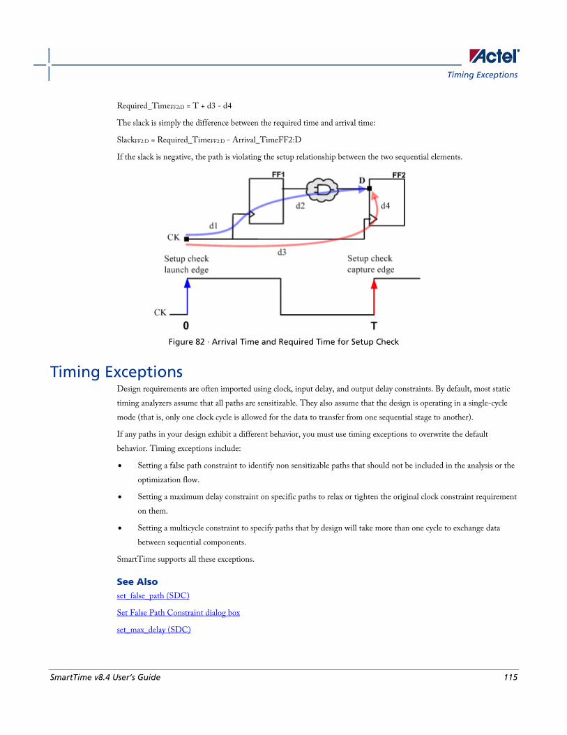
Timing Exceptions
SmartTime v8.4 User’s Guide 115
Required_TimeFF2:D = T + d3 - d4
The slack is simply the difference between the required time and arrival time:
SlackFF2:D = Required_TimeFF2:D - Arrival_TimeFF2:D
If the slack is negative, the path is violating the setup relationship between the two sequential elements.
Figure 82 · Arrival Time and Required Time for Setup Check
Timing Exceptions Design requirements are often imported using clock, input delay, and output delay constraints. By default, most static
timing analyzers assume that all paths are sensitizable. They also assume that the design is operating in a single-cycle
mode (that is, only one clock cycle is allowed for the data to transfer from one sequential stage to another).
If any paths in your design exhibit a different behavior, you must use timing exceptions to overwrite the default
behavior. Timing exceptions include:
• Setting a false path constraint to identify non sensitizable paths that should not be included in the analysis or the
optimization flow.
• Setting a maximum delay constraint on specific paths to relax or tighten the original clock constraint requirement
on them.
• Setting a multicycle constraint to specify paths that by design will take more than one cycle to exchange data
between sequential components.
SmartTime supports all these exceptions.
See Also set_false_path (SDC)
Set False Path Constraint dialog box
set_max_delay (SDC)
Timing Concepts
116 SmartTime v8.4 User’s Guide
Set Maximum Delay Constraint dialog box
set_multicycle_path (SDC)
Set Multicycle Constraint dialog box
Clock Skew The clock skew between two different sequential components is the difference between the insertion delays from the
clock source to the clock pins of these components. SmartTime calculates the arrival time at the clock pin of each
sequential component. Then it subtracts the arrival time at the receiving component from the arrival time at the
launching component to obtain an accurate clock skew.
Both setup and hold checks must account for clock skew. However, for setup check, SmartTime looks for the smallest
skew. This skew is computed by using the maximum insertion delay to the launching sequential component and the
shortest insertion delay to the receiving component.
For hold check, SmartTime looks for the largest skew. This skew is computed by using the shortest insertion delay to
the launching sequential component and the largest insertion delay to the receiving component. SmartTime makes this
distinction automatically.
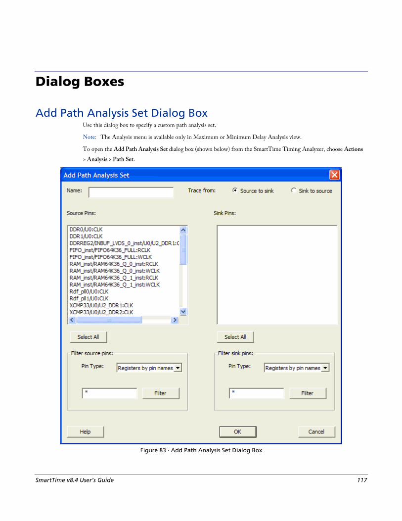
SmartTime v8.4 User’s Guide 117
Dialog Boxes
Add Path Analysis Set Dialog Box Use this dialog box to specify a custom path analysis set.
Note: The Analysis menu is available only in Maximum or Minimum Delay Analysis view.
To open the Add Path Analysis Set dialog box (shown below) from the SmartTime Timing Analyzer, choose Actions
> Analysis > Path Set.
Figure 83 · Add Path Analysis Set Dialog Box
Dialog Boxes
118 SmartTime v8.4 User’s Guide
Name Enter the name of your path set.
Trace from Select whether you want to trace connected pins from Source to sink or from Sink to source. By default, the pins are
traced Source to sink.
Source Pins Displays a list of available and valid source pins. You can select multiple pins. To select all source pins, click the Select
All button beneath the Source Pins list.
Select All Selects all the pins in the Source Pins list to include in the path analysis set.
Filter Source Pins Enables you to specify thesource Pin Type and the Filter. The default pin type is Registers by pin name. You can
specify any string value for the Filter. If you change the pin type, the Source Pins shows the updated list of available
source pins.
Sink Pins Displays list of available and valid pins. You can select multiple pins. To select all source pins, click the Select All
button beneath the Sink Pins list.
Select All Selects all the pins in the Sink Pins list to include in the path analysis set.
Filter Sink Pins Enables you to specify thesink Pin Type and the Filter. The default pin type is Registers (by pin). You can specify any
string value for the Filter. If you change the pin type, the Sink Pins shows the updated list of available sink pins.
Analysis Set Properties Dialog Box Use this dialog box to view information about the user created set.
To open the Analysis Set Properties dialog box (shown below) from the Timing Analysis View, right-click any user-
created set in the Domain Browser, and choose Properties from the shortcut menu.
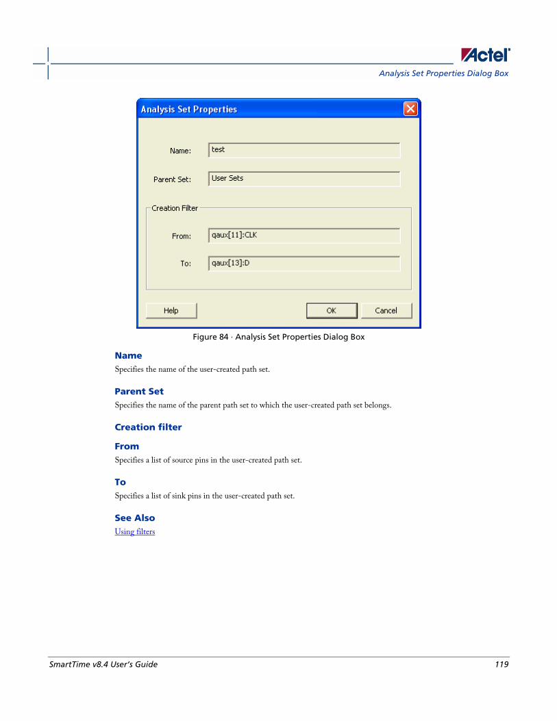
Analysis Set Properties Dialog Box
SmartTime v8.4 User’s Guide 119
Figure 84 · Analysis Set Properties Dialog Box
Name Specifies the name of the user-created path set.
Parent Set Specifies the name of the parent path set to which the user-created path set belongs.
Creation filter
From Specifies a list of source pins in the user-created path set.
To Specifies a list of sink pins in the user-created path set.
See Also Using filters
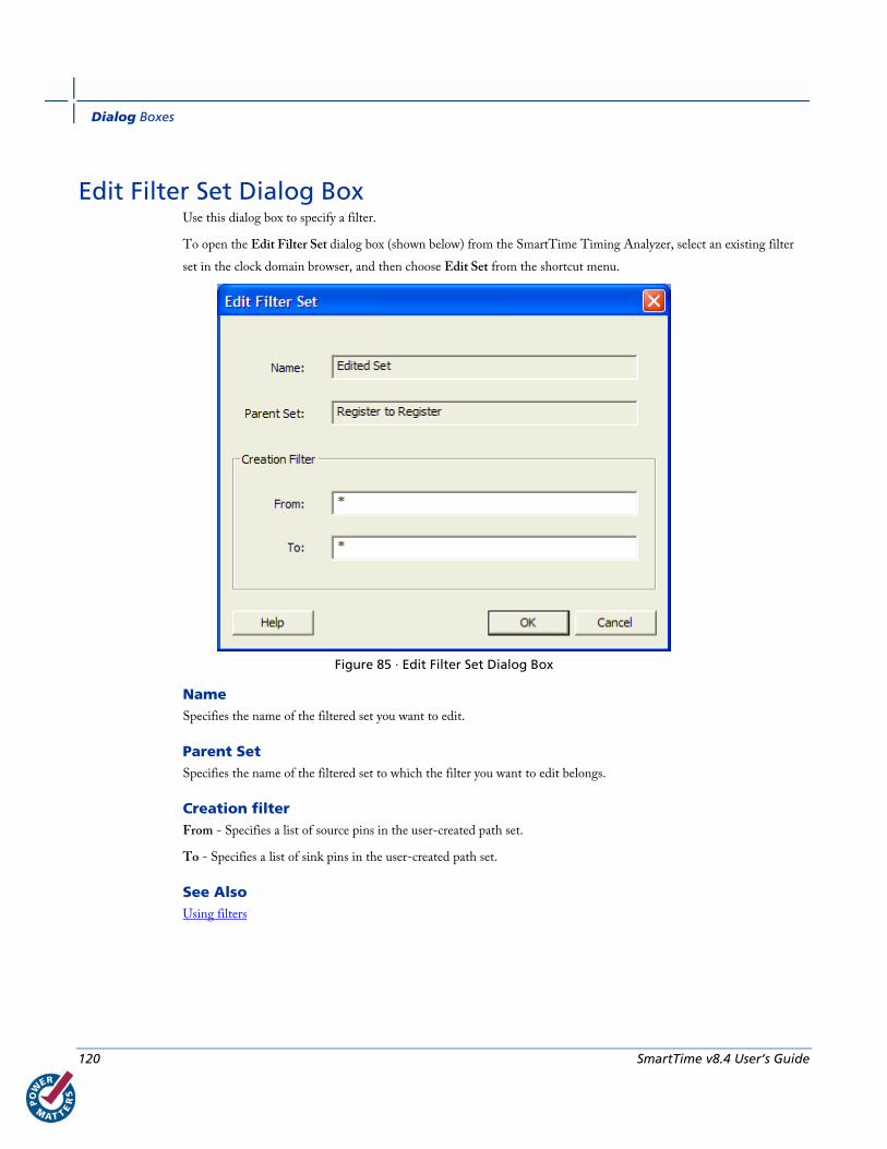
Dialog Boxes
120 SmartTime v8.4 User’s Guide
Edit Filter Set Dialog Box Use this dialog box to specify a filter.
To open the Edit Filter Set dialog box (shown below) from the SmartTime Timing Analyzer, select an existing filter
set in the clock domain browser, and then choose Edit Set from the shortcut menu.
Figure 85 · Edit Filter Set Dialog Box
Name Specifies the name of the filtered set you want to edit.
Parent Set Specifies the name of the filtered set to which the filter you want to edit belongs.
Creation filter From - Specifies a list of source pins in the user-created path set.
To - Specifies a list of sink pins in the user-created path set.
See Also Using filters
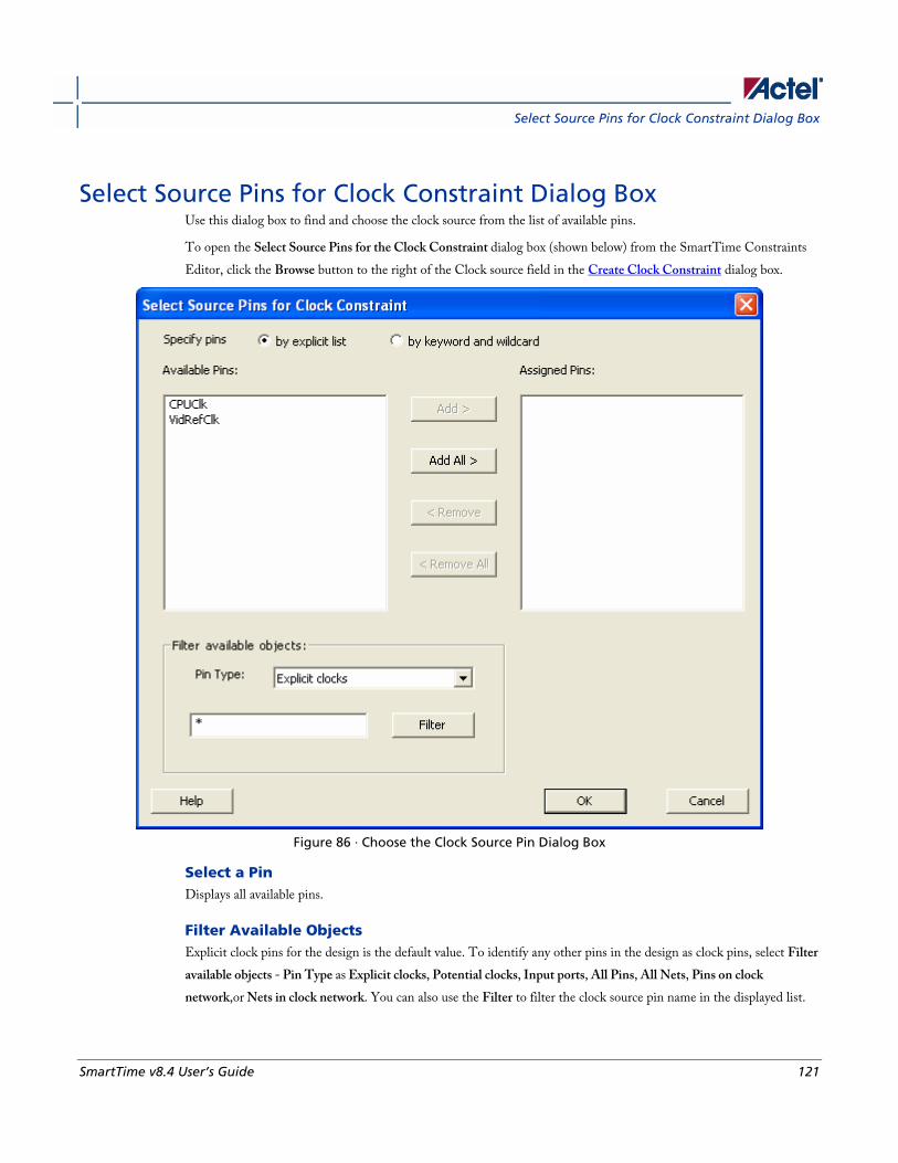
Select Source Pins for Clock Constraint Dialog Box
SmartTime v8.4 User’s Guide 121
Select Source Pins for Clock Constraint Dialog Box Use this dialog box to find and choose the clock source from the list of available pins.
To open the Select Source Pins for the Clock Constraint dialog box (shown below) from the SmartTime Constraints
Editor, click the Browse button to the right of the Clock source field in the Create Clock Constraint dialog box.
Figure 86 · Choose the Clock Source Pin Dialog Box
Select a Pin Displays all available pins.
Filter Available Objects Explicit clock pins for the design is the default value. To identify any other pins in the design as clock pins, select Filter
available objects - Pin Type as Explicit clocks, Potential clocks, Input ports, All Pins, All Nets, Pins on clock
network,or Nets in clock network. You can also use the Filter to filter the clock source pin name in the displayed list.
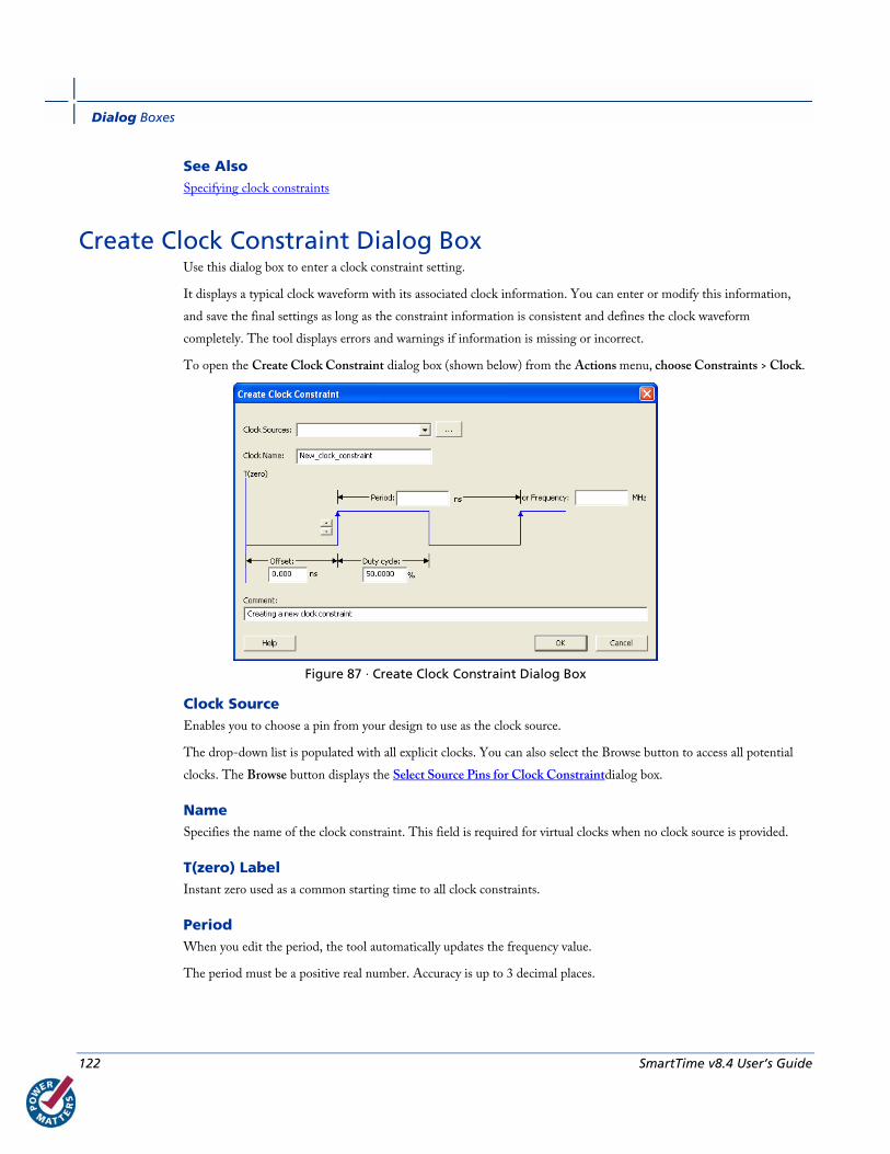
Dialog Boxes
122 SmartTime v8.4 User’s Guide
See Also Specifying clock constraints
Create Clock Constraint Dialog Box Use this dialog box to enter a clock constraint setting.
It displays a typical clock waveform with its associated clock information. You can enter or modify this information,
and save the final settings as long as the constraint information is consistent and defines the clock waveform
completely. The tool displays errors and warnings if information is missing or incorrect.
To open the Create Clock Constraint dialog box (shown below) from the Actions menu, choose Constraints > Clock.
Figure 87 · Create Clock Constraint Dialog Box
Clock Source Enables you to choose a pin from your design to use as the clock source.
The drop-down list is populated with all explicit clocks. You can also select the Browse button to access all potential
clocks. The Browse button displays the Select Source Pins for Clock Constraintdialog box.
Name Specifies the name of the clock constraint. This field is required for virtual clocks when no clock source is provided.
T(zero) Label Instant zero used as a common starting time to all clock constraints.
Period When you edit the period, the tool automatically updates the frequency value.
The period must be a positive real number. Accuracy is up to 3 decimal places.
Create Generated Clock Constraint Dialog Box
SmartTime v8.4 User’s Guide 123
Frequency When you edit the frequency, the tool automatically updates the period value.
The frequency must be a positive real number. Accuracy is up to 3 decimal places.
Starting Edge Selector Enables you to switch between rising and falling edges and updates the clock waveform.
If the current setting of starting edge is rising, you can change the starting edge from rising to falling.
If the current setting of starting edge is falling, you can change the starting edge from falling to rising.
Duty Cycle This number specifies the percentage of the overall period that the clock pulse is high.
The duty cycle must be a positive real number. Accuracy is up to 4 decimal places. Default value is 50%.
Offset The offset must be a positive real number. Accuracy is up to 2 decimal places. Default value is 0.
Comment Enables you to save a single line of text that describes the clock constraints purpose.
See Also create_clock (SDC)
Clock definition
Specifying clock constraint
Create Generated Clock Constraint Dialog Box Use this dialog box to specify generated clock constraint settings.
It displays a relationship between the clock source and its reference clock. You can enter or modify this information,
and save the final settings as long as the constraint information is consistent. The tool displays errors and warnings if
the information is missing or incorrect.
To open the Create Generated Clock Constraint dialog box (shown below) from the SmartTime Constraints Editor,
choose Actions > Constraints > Generated Clock.

Dialog Boxes
124 SmartTime v8.4 User’s Guide
Figure 88 · Create Generated Clock Constraint
Clock Pin Enables you to choose a pin from your design to use as a generated clock source.
The drop-down list is populated with all unconstrained explicit clocks. You can also select the Browse button to access
all potential clocks and pins from the clock network. The Browse button displays the Select Generated Clock Source
dialog box.
Clock Reference Enables you to choose a pin from your design to use as a generated reference pin.
Generated Clock Name Specifies the name of the clock constraint. This field is required for virtual clocks when no clock source is provided.
Generated Frequency The generated frequency is a factor of reference frequency defined with a multiplication element and/or a division
element.
Generated Waveform The generated waveform could be either the same as or inverted w.r.t. the reference waveform.
Comment Enables you to save a single line of text that describes the generated clock constraints purpose.
See Also create_generated_clock (SDC)
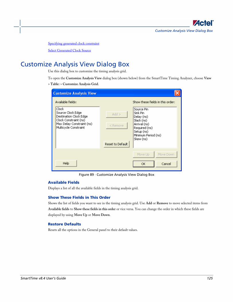
Customize Analysis View Dialog Box
SmartTime v8.4 User’s Guide 125
Specifying generated clock constraint
Select Generated Clock Source
Customize Analysis View Dialog Box Use this dialog box to customize the timing analysis grid.
To open the Customize Analysis View dialog box (shown below) from the SmartTime Timing Analyzer, choose View
> Table: > Customize Analysis Grid.
Figure 89 · Customize Analysis View Dialog Box
Available Fields Displays a list of all the available fields in the timing analysis grid.
Show These Fields in This Order Shows the list of fields you want to see in the timing analysis grid. Use Add or Remove to move selected items from
Available fields to Show these fields in this order or vice versa. You can change the order in which these fields are
displayed by using Move Up or Move Down.
Restore Defaults Resets all the options in the General panel to their default values.
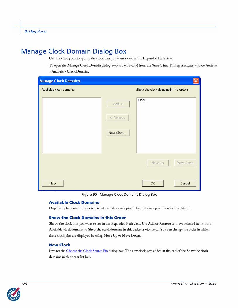
Dialog Boxes
126 SmartTime v8.4 User’s Guide
Manage Clock Domain Dialog Box Use this dialog box to specify the clock pins you want to see in the Expanded Path view.
To open the Manage Clock Domain dialog box (shown below) from the SmartTime Timing Analyzer, choose Actions
> Analysis > Clock Domain.
Figure 90 · Manage Clock Domains Dialog Box
Available Clock Domains Displays alphanumerically sorted list of available clock pins. The first clock pin is selected by default.
Show the Clock Domains in this Order Shows the clock pins you want to see in the Expanded Path view. Use Add or Remove to move selected items from
Available clock domains to Show the clock domains in this order or vice versa. You can change the order in which
these clock pins are displayed by using Move Up or Move Down.
New Clock Invokes the Choose the Clock Source Pin dialog box. The new clock gets added at the end of the Show the clock
domains in this order list box.
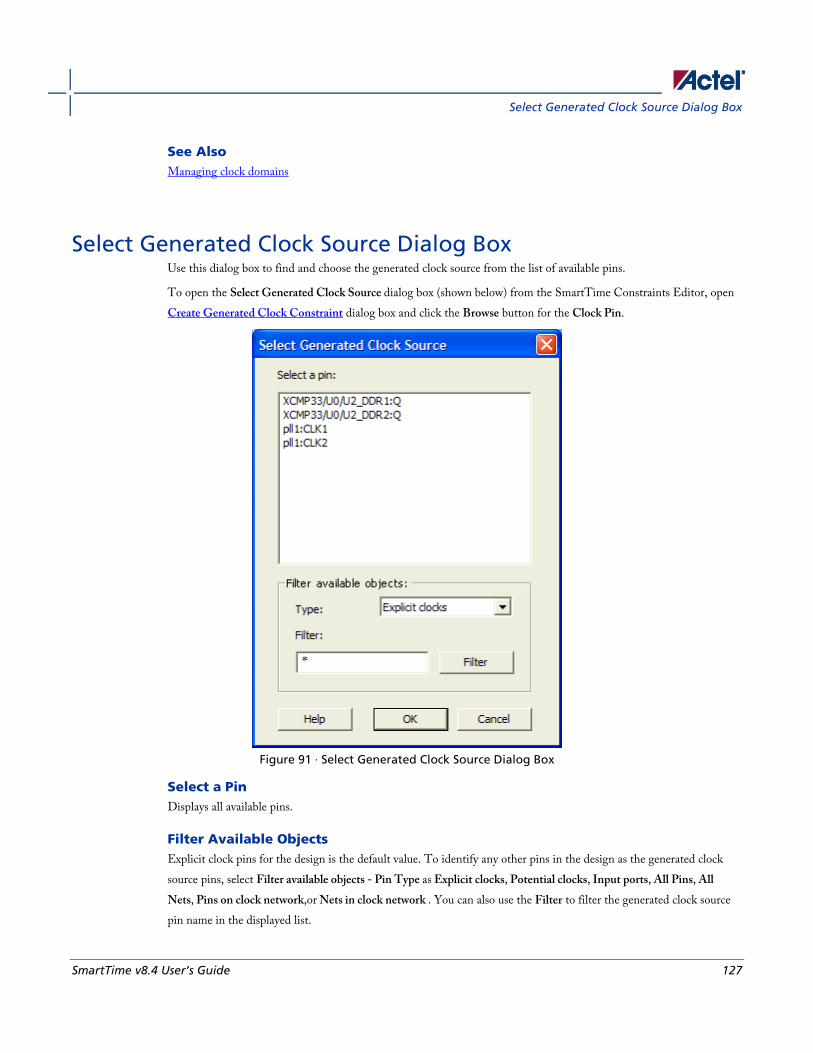
Select Generated Clock Source Dialog Box
SmartTime v8.4 User’s Guide 127
See Also Managing clock domains
Select Generated Clock Source Dialog Box Use this dialog box to find and choose the generated clock source from the list of available pins.
To open the Select Generated Clock Source dialog box (shown below) from the SmartTime Constraints Editor, open
Create Generated Clock Constraint dialog box and click the Browse button for the Clock Pin.
Figure 91 · Select Generated Clock Source Dialog Box
Select a Pin Displays all available pins.
Filter Available Objects Explicit clock pins for the design is the default value. To identify any other pins in the design as the generated clock
source pins, select Filter available objects - Pin Type as Explicit clocks, Potential clocks, Input ports, All Pins, All
Nets, Pins on clock network,or Nets in clock network . You can also use the Filter to filter the generated clock source
pin name in the displayed list.
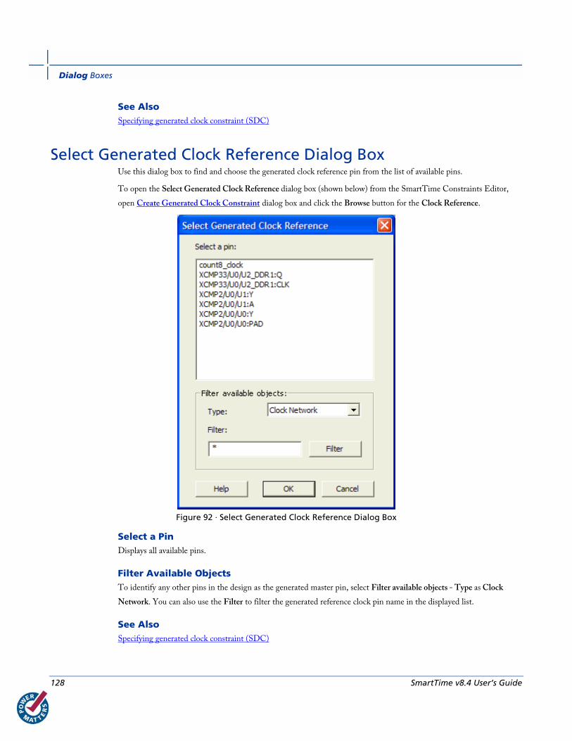
Dialog Boxes
128 SmartTime v8.4 User’s Guide
See Also Specifying generated clock constraint (SDC)
Select Generated Clock Reference Dialog Box Use this dialog box to find and choose the generated clock reference pin from the list of available pins.
To open the Select Generated Clock Reference dialog box (shown below) from the SmartTime Constraints Editor,
open Create Generated Clock Constraint dialog box and click the Browse button for the Clock Reference.
Figure 92 · Select Generated Clock Reference Dialog Box
Select a Pin Displays all available pins.
Filter Available Objects To identify any other pins in the design as the generated master pin, select Filter available objects - Type as Clock
Network. You can also use the Filter to filter the generated reference clock pin name in the displayed list.
See Also Specifying generated clock constraint (SDC)
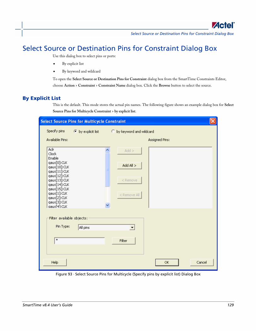
Select Source or Destination Pins for Constraint Dialog Box
SmartTime v8.4 User’s Guide 129
Select Source or Destination Pins for Constraint Dialog Box Use this dialog box to select pins or ports:
• By explicit list
• By keyword and wildcard
To open the Select Source or Destination Pins for Constraint dialog box from the SmartTime Constraints Editor,
choose Action > Constraint > Constraint Name dialog box. Click the Browse button to select the source.
By Explicit List This is the default. This mode stores the actual pin names. The following figure shows an example dialog box for Select
Source Pins for Multicycle Constraint > by explicit list.
Figure 93 · Select Source Pins for Multicycle (Specify pins by explicit list) Dialog Box
Dialog Boxes
130 SmartTime v8.4 User’s Guide
Available Objects The list box displays the available valid objects. If you change the filter value, the list box shows the available objects
based on the filter.
Use Add, Add All, Remove, Remove All to add or delete pins from the Assigned Pins list.
Filter Available Objects Pin type – Specifies the filter on the available object. This can be by Explicit clocks, Potential clocks, Input ports, All
Pins, All Nets, Pins on clock network,or Nets in clock network
Filter Specifies the filter based on which the Available Pins list shows the pin names. The default is *. You can specify any
string value.
By Keyword and Wildcard This mode stores the filter only. It does not store the actual pin names. The constraints created using this mode get
exported with the SDC accessors (get_ports, get_pins, etc.).The following figure shows an example dialog box for
Select Source Pins for Multicycle Constraint > by keyword and wildcard.
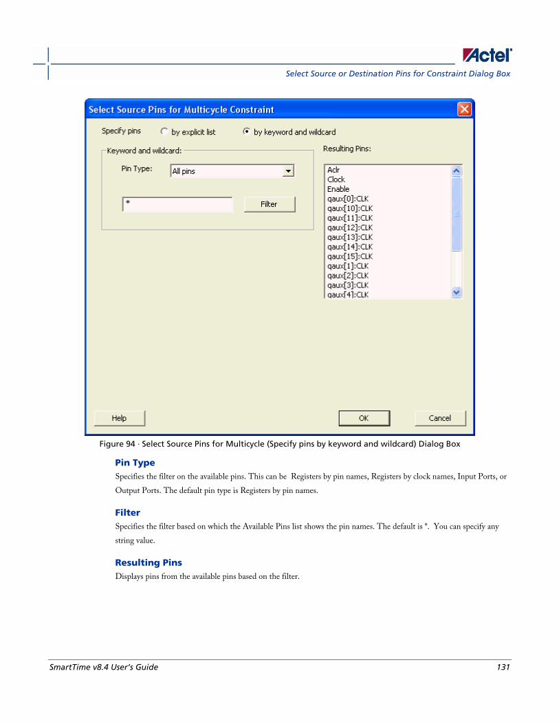
Select Source or Destination Pins for Constraint Dialog Box
SmartTime v8.4 User’s Guide 131
Figure 94 · Select Source Pins for Multicycle (Specify pins by keyword and wildcard) Dialog Box
Pin Type Specifies the filter on the available pins. This can be Registers by pin names, Registers by clock names, Input Ports, or
Output Ports. The default pin type is Registers by pin names.
Filter Specifies the filter based on which the Available Pins list shows the pin names. The default is *. You can specify any
string value.
Resulting Pins Displays pins from the available pins based on the filter.

Dialog Boxes
132 SmartTime v8.4 User’s Guide
Set False Path Constraint Dialog Box Use this dialog box to define specific timing paths as being false.
This constraint removes timing requirements on these false paths so that they are not considered during the timing
analysis. The path starting points are the input ports or register clock pins and path ending points are the register data
pins or output ports. This constraint disables setup and hold checking for the specified paths.
Note: The false path information always takes precedence over multiple cycle path information and overrides
maximum delay constraints.
To open the Set False Path Constraint dialog box (shown below) from the SmartTime Constraints Editor, choose
Actions > Constraints > False Path.
Figure 95 · Set False Path Constraint Dialog Box
Set Clock Source Latency Dialog Box
SmartTime v8.4 User’s Guide 133
From Specifies the starting points for false path. A valid timing starting point is a clock, a primary input, an inout port, or a
clock pin of a sequential cell.
Through Specifies a list of pins, ports, cells, or nets through which the disabled paths must pass.
To Specifies the ending points for false path. A valid timing ending point is a clock, a primary output, an inout port, or a
data pin of a sequential cell.
Comment Enables you to provide comments for this constraint.
See Also Specifying false path constraint
Set Clock Source Latency Dialog Box Use this dialog box to define the delay between an external clock source and the definition pin of a clock within
SmartTime.
To open the Set Clock Source Latency dialog box (shown below) from the Timing Analysis View, you must first create
a clock constraint. From the Actions menu, choose Constraint > Latency.

Dialog Boxes
134 SmartTime v8.4 User’s Guide
Figure 96 · Set Clock Source Latency Dialog Box
Clock Port or Pin Displays a list of clock ports or pins that do not already have a clock source latency specified. Select the clock port or
pin for which you are specifying the clock source latency.
Late Rise Specifies the largest possible latency, in nanoseconds, of the rising clock edge at the clock port or pin selected, with
respect to its source. Negative values are acceptable, but may lead to overly optimistic analysis.
Early Rise Specifies the smallest possible latency, in nanoseconds, of the rising clock edge at the clock port or pin selected, with
respect to its source. Negative values are acceptable, but may lead to overly optimistic analysis.
Late Fall Specifies the largest possible latency, in nanoseconds, of the falling clock edge at the clock port or pin selected, with
respect to its source. Negative values are acceptable, but may lead to overly optimistic analysis.
Set Constraint to Disable Timing Arcs Dialog Box
SmartTime v8.4 User’s Guide 135
Early Fall Specifies the smallest possible latency, in nanoseconds, of the falling clock edge at the clock port or pin selected, with
respect to its source. Negative values are acceptable, but may lead to overly optimistic analysis.
Clock Edges Select the latency for the rising and falling edges:
Falling same as rising: Specifies that Rising and Falling clock edges have the same latency.
Early same as late : Specifies that the clock source latency should be considered as a single value, not a range from
"early" to ‘"late".
Comment Enables you to save a single line of text that describes the clock source latency.
See Also Specifying clock constraints
Set Constraint to Disable Timing Arcs Dialog Box Use this dialog box to specify the timing arcs being disabled to fix the combinational loops in the design.
To open the Set Constraint to Disable Timing Arcs dialog box (shown below) from the Timing Analysis View. From
the Actions menu, choose Constraint > Disable Timing.
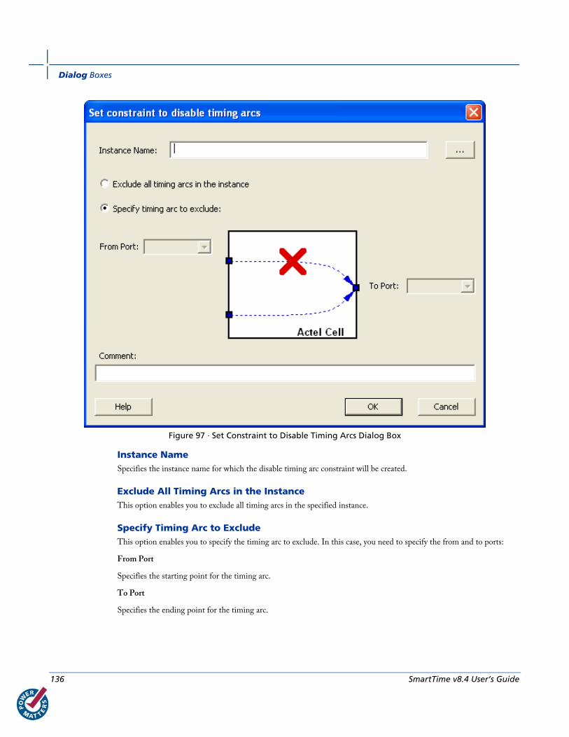
Dialog Boxes
136 SmartTime v8.4 User’s Guide
Figure 97 · Set Constraint to Disable Timing Arcs Dialog Box
Instance Name Specifies the instance name for which the disable timing arc constraint will be created.
Exclude All Timing Arcs in the Instance This option enables you to exclude all timing arcs in the specified instance.
Specify Timing Arc to Exclude This option enables you to specify the timing arc to exclude. In this case, you need to specify the from and to ports:
From Port
Specifies the starting point for the timing arc.
To Port
Specifies the ending point for the timing arc.

Set Input Delay Constraint Dialog Box
SmartTime v8.4 User’s Guide 137
Comment Enables you to save a single line of text that describes the disable timing arc.
See Also Specifying Disable Timing Constraint
Set Input Delay Constraint Dialog Box Use this dialog box to apply input delay constraints or external setup/hold constraints. This constraint defines the
arrival time of an input relative to a clock.
To open the Set Input Delay Constraint dialog box (shown below) from the SmartTime Constraints Editor, choose
Actions > Constraints > Input Delay.
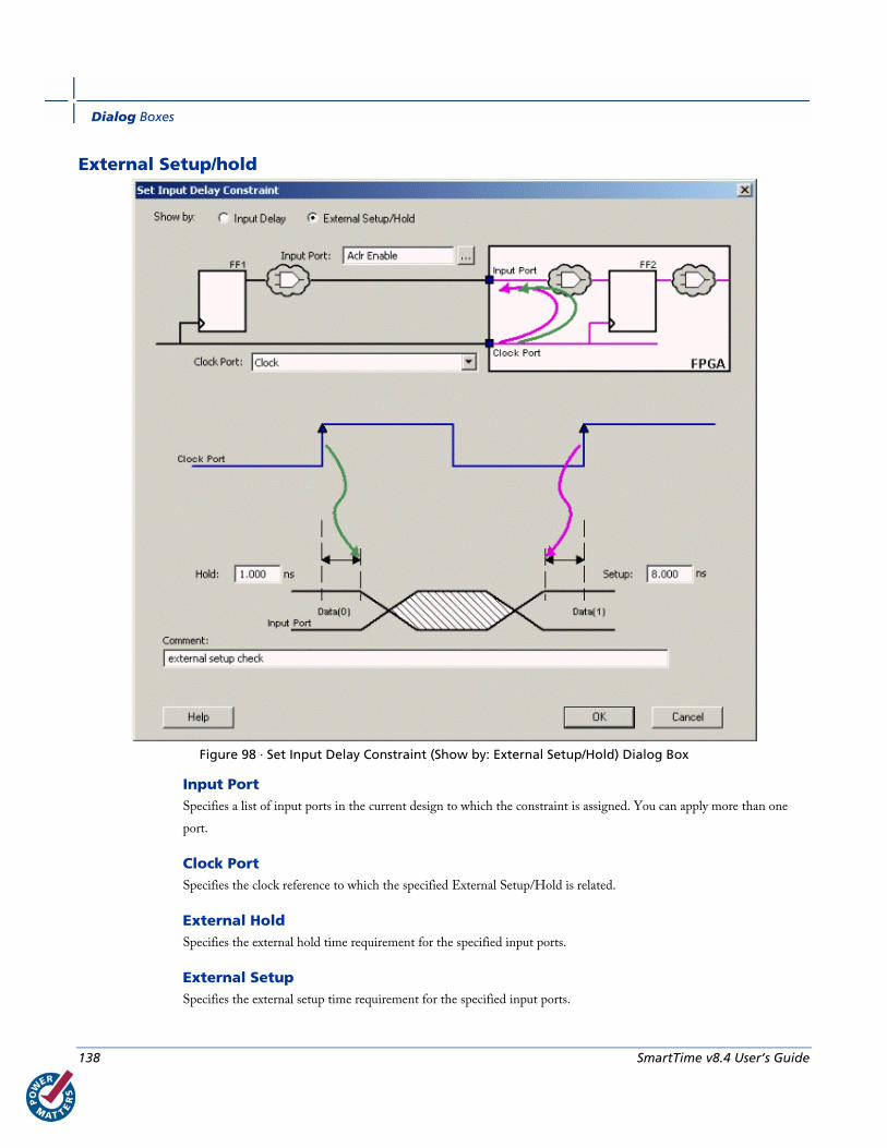
Dialog Boxes
138 SmartTime v8.4 User’s Guide
External Setup/hold
Figure 98 · Set Input Delay Constraint (Show by: External Setup/Hold) Dialog Box
Input Port Specifies a list of input ports in the current design to which the constraint is assigned. You can apply more than one
port.
Clock Port Specifies the clock reference to which the specified External Setup/Hold is related.
External Hold Specifies the external hold time requirement for the specified input ports.
External Setup Specifies the external setup time requirement for the specified input ports.
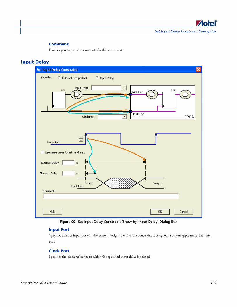
Set Input Delay Constraint Dialog Box
SmartTime v8.4 User’s Guide 139
Comment Enables you to provide comments for this constraint.
Input Delay
Figure 99 · Set Input Delay Constraint (Show by: Input Delay) Dialog Box
Input Port Specifies a list of input ports in the current design to which the constraint is assigned. You can apply more than one
port.
Clock Port Specifies the clock reference to which the specified input delay is related.
Dialog Boxes
140 SmartTime v8.4 User’s Guide
Clock edge Indicates the launching edge of the clock.
Use max delay for both min and max Specifies that the minimum input delay uses the same value as the maximum input delay.
Maximum Delay Specifies that the delay refers to the longest path arriving at the specified input.
Minimum Delay Specifies that the delay refers to the shortest path arriving at the specified input.
Comment Enables you to provide comments for this constraint.
See Also Specifying input timing delay constraint
Set Maximum Delay Constraint Dialog Box Use this dialog box to specify the required maximum delay for timing paths in the current design.
SmartTime automatically derives the individual maximum delay targets from clock waveforms and port input or output
delays. So the maximum delay constraint is a timing exception. This constraint overrides the default single cycle timing
relationship for one or more timing paths. This constraint also overrides a multiple cycle path constraint.
To open the Set Maximum Delay Constraint dialog box (shown below) from the SmartTime Constraints Editor,
choose Actions > Constraints > Max Delay.
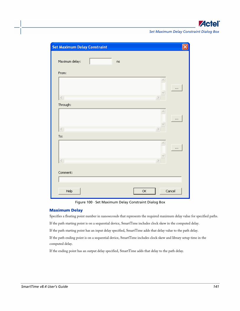
Set Maximum Delay Constraint Dialog Box
SmartTime v8.4 User’s Guide 141
Figure 100 · Set Maximum Delay Constraint Dialog Box
Maximum Delay Specifies a floating point number in nanoseconds that represents the required maximum delay value for specified paths.
If the path starting point is on a sequential device, SmartTime includes clock skew in the computed delay.
If the path starting point has an input delay specified, SmartTime adds that delay value to the path delay.
If the path ending point is on a sequential device, SmartTime includes clock skew and library setup time in the
computed delay.
If the ending point has an output delay specified, SmartTime adds that delay to the path delay.
Dialog Boxes
142 SmartTime v8.4 User’s Guide
From Specifies the starting points for max delay constraint. A valid timing starting point is a clock, a primary input, an inout
port, or a clock pin of a sequential cell.
Through Specifies the through points for the multiple cycle constraint.
To Specifies the ending points for maximum delay constraint. A valid timing ending point is a clock, a primary output, an
inout port, or a data pin of a sequential cell.
Comment Enables you to provide comments for this constraint.
See Also Specifying maximum delay constraint
Set Minimum Delay Constraint Dialog Box Use this dialog box to specify the required minimum delay for timing paths in the current design.
SmartTime automatically derives the individual minimum delay targets from clock waveforms and port input or output
delays. So the minimum delay constraint is a timing exception. This constraint overrides the default single cycle timing
relationship for one or more timing paths. This constraint also overrides a multiple cycle path constraint.
To open the Set Minimum Delay Constraint dialog box (shown below) from the SmartTime Constraints Editor,
choose Actions > Constraints > Min Delay.
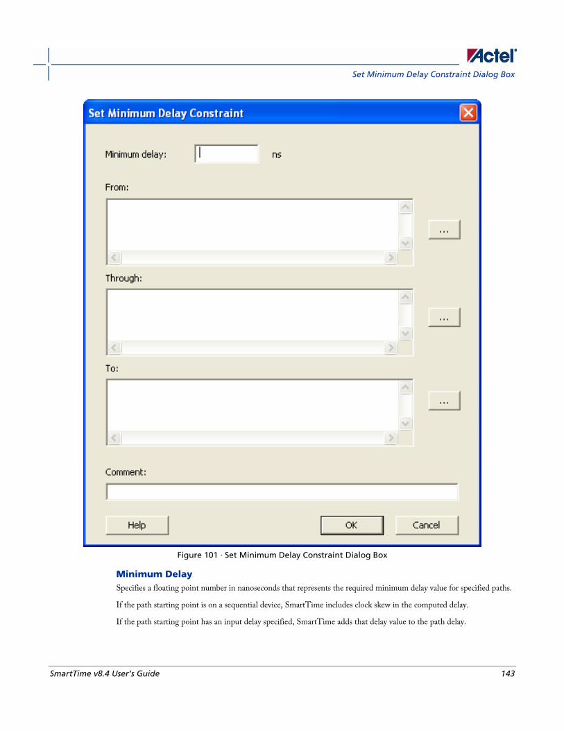
Set Minimum Delay Constraint Dialog Box
SmartTime v8.4 User’s Guide 143
Figure 101 · Set Minimum Delay Constraint Dialog Box
Minimum Delay Specifies a floating point number in nanoseconds that represents the required minimum delay value for specified paths.
If the path starting point is on a sequential device, SmartTime includes clock skew in the computed delay.
If the path starting point has an input delay specified, SmartTime adds that delay value to the path delay.
Dialog Boxes
144 SmartTime v8.4 User’s Guide
If the path ending point is on a sequential device, SmartTime includes clock skew and library setup time in the
computed delay.
If the ending point has an output delay specified, SmartTime adds that delay to the path delay.
From Specifies the starting points for minimum delay constraint. A valid timing starting point is a clock, a primary input, an
input port, or a clock pin of a sequential cell.
Through Specifies the through points for the multiple cycle constraint.
To Specifies the ending points for minimum delay constraint. A valid timing ending point is a clock, a primary output, an
input port, or a data pin of a sequential cell.
Comment Enables you to provide comments for this constraint.
See Also Specifying minimum delay constraint
Set Multicycle Constraint Dialog Box Use this dialog box to specify the paths that take multiple clock cycles in the current design.
Setting the multiple-cycle paths constraint overrides the single-cycle timing relationships between sequential elements
by specifying the number of cycles that the data path must have for setup or hold checks.
Note: The false path information always takes precedence over multiple cycle path information. A specific maximum
delay constraint overrides a general multiple cycle path constraint.
To open the Set Multicycle Constraint dialog box (shown below) from the SmartTime Constraints Editor, choose
Actions > Constraint> Multicycle.
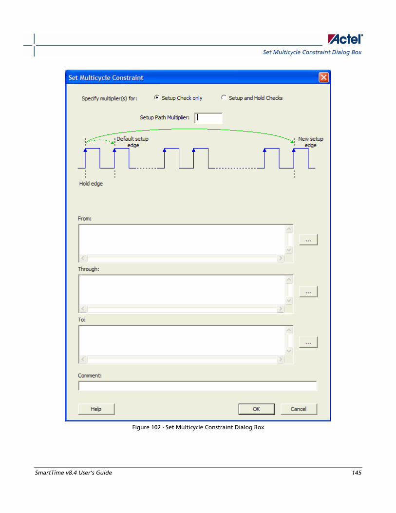
Set Multicycle Constraint Dialog Box
SmartTime v8.4 User’s Guide 145
Figure 102 · Set Multicycle Constraint Dialog Box
Dialog Boxes
146 SmartTime v8.4 User’s Guide
Setup Path Multiplier Specifies an integer value that represents a number of cycles the data path must have for a setup check. No hold check
will be performed.
From Specifies the starting points for the multiple cycle constraint. A valid timing starting point is a clock, a primary input,
an inout port, or the clock pin of a sequential cell.
Through Specifies the through points for the multiple cycle constraint.
To Specifies the ending points for the multiple cycle constraint. A valid timing ending point is a clock, a primary output,
an inout port, or a data pin of a sequential cell.
Comment Enables you to provide comments for this constraint.
When you select the Setup and Hold Checks option, an additional field appears in this dialog box: Hold Path
Multiplier.

Set Multicycle Constraint Dialog Box
SmartTime v8.4 User’s Guide 147
Figure 103 · Set Multicycle Constraint Dialog Box with Setup and Hold Checks Selected
Dialog Boxes
148 SmartTime v8.4 User’s Guide
Hold Path Multiplier Specifies an integer value that represents a number of cycles the data path must have for a hold check, starting from one
cycle before the setup check edge.
See Also Specifying multicycle constraint
Set Output Delay Constraint Dialog Box Use this dialog box to apply output delay constraints. This constraint defines the output delay of an output relative to a
clock.
To open the Set Output Delay Constraint dialog box (shown below) from the SmartTime Constraints Editor, choose
Actions > Constraints > Output Delay.

Set Output Delay Constraint Dialog Box
SmartTime v8.4 User’s Guide 149
Clock-to-Output
Figure 104 · Set Output Delay (Show By: Clock-to-Output) Dialog Box
Output Port Specifies a list of output ports in the current design to which the constraint is assigned. You can apply more than one
port.
Clock Port Specifies the clock reference to which the specified Clock-to-Output is related.
Clock edge Indicates the clock edge of the launched edge.
Dialog Boxes
150 SmartTime v8.4 User’s Guide
Maximum Delay Specifies the delay for the longest path from the clock port to the output port. This constraint includes the
combinational path delay from output of the launched edge to the output port.
Minimum Delay Specifies the delay for the shortest path from the clock port to the output port. This constraint includes the
combinational path delay from output of the launched edge to the output port.
Comment Enables you to provide comments for this constraint.
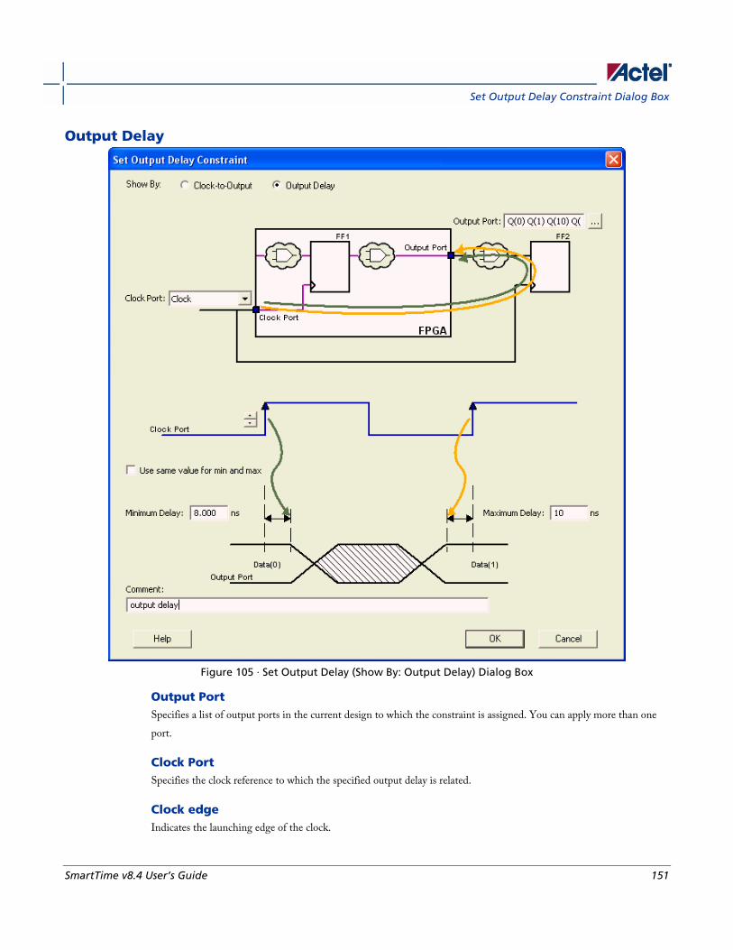
Set Output Delay Constraint Dialog Box
SmartTime v8.4 User’s Guide 151
Output Delay
Figure 105 · Set Output Delay (Show By: Output Delay) Dialog Box
Output Port Specifies a list of output ports in the current design to which the constraint is assigned. You can apply more than one
port.
Clock Port Specifies the clock reference to which the specified output delay is related.
Clock edge Indicates the launching edge of the clock.
Dialog Boxes
152 SmartTime v8.4 User’s Guide
Maximum Delay Specifies the delay for the longest path from the specified output to the captured edge. This represents a combinational
path delay to a register outside the current design plus the library setup time.
Minimum Delay Specifies the delay for the shortest path from the specified output to the captured edge. This represents a combinational
path delay to a register outside the current design plus the library hold time.
Comment Enables you to provide comments for this constraint.
See Also Specifying output timing delay constraint
SmartTime Options Dialog Box Use this dialog box to specify the SmartTime options to perform timing analysis.
This interface includes the following categories:
• General
• Analysis View
• Advanced
To open the SmartTime Options dialog box (shown below) from the SmartTime tool, choose Tools > Options.
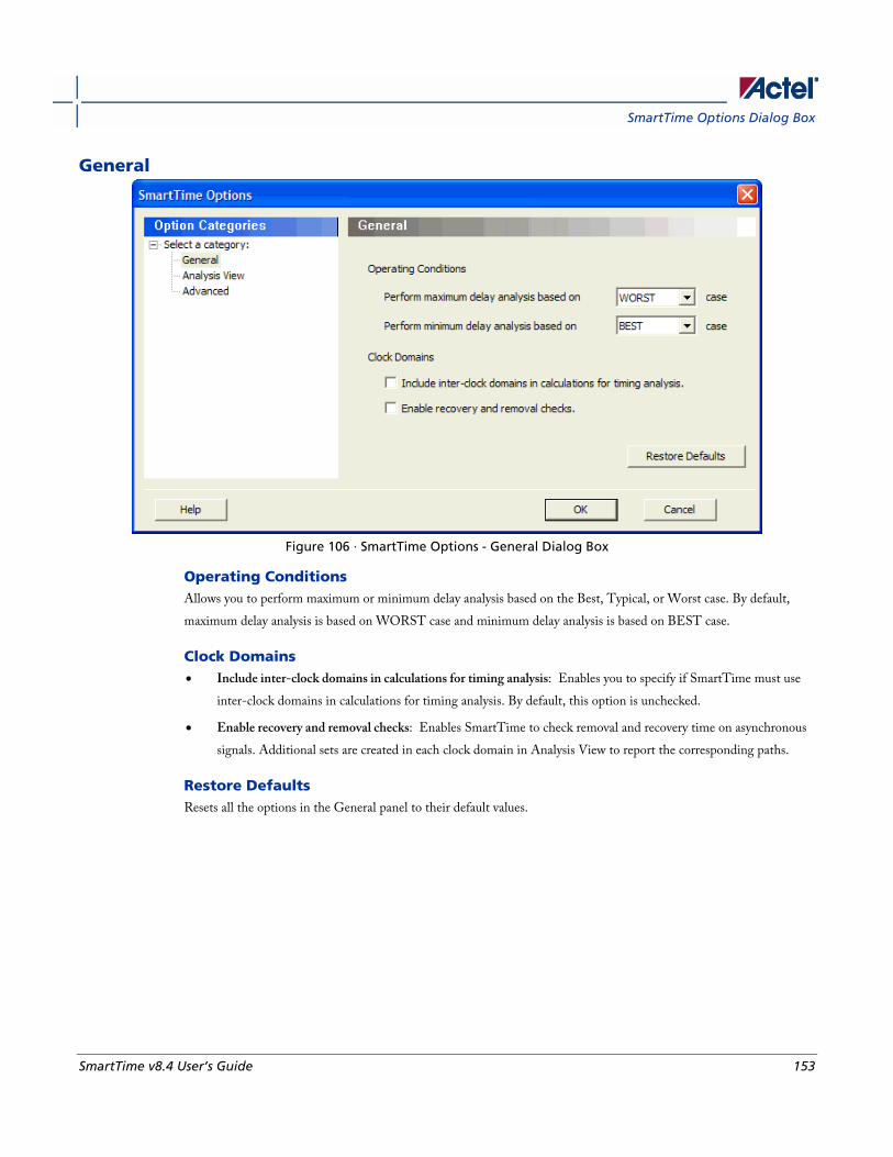
SmartTime Options Dialog Box
SmartTime v8.4 User’s Guide 153
General
Figure 106 · SmartTime Options - General Dialog Box
Operating Conditions Allows you to perform maximum or minimum delay analysis based on the Best, Typical, or Worst case. By default,
maximum delay analysis is based on WORST case and minimum delay analysis is based on BEST case.
Clock Domains • Include inter-clock domains in calculations for timing analysis: Enables you to specify if SmartTime must use
inter-clock domains in calculations for timing analysis. By default, this option is unchecked.
• Enable recovery and removal checks: Enables SmartTime to check removal and recovery time on asynchronous
signals. Additional sets are created in each clock domain in Analysis View to report the corresponding paths.
Restore Defaults Resets all the options in the General panel to their default values.
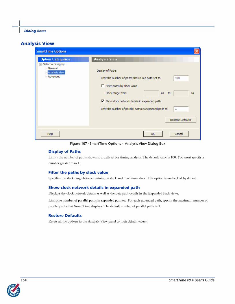
Dialog Boxes
154 SmartTime v8.4 User’s Guide
Analysis View
Figure 107 · SmartTime Options - Analysis View Dialog Box
Display of Paths Limits the number of paths shown in a path set for timing analysis. The default value is 100. You must specify a
number greater than 1.
Filter the paths by slack value Specifies the slack range between minimum slack and maximum slack. This option is unchecked by default.
Show clock network details in expanded path Displays the clock network details as well as the data path details in the Expanded Path views.
Limit the number of parallel paths in expanded path to: For each expanded path, specify the maximum number of
parallel paths that SmartTime displays. The default number of parallel paths is 1.
Restore Defaults Resets all the options in the Analysis View panel to their default values.
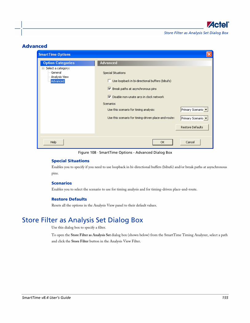
Store Filter as Analysis Set Dialog Box
SmartTime v8.4 User’s Guide 155
Advanced
Figure 108 · SmartTime Options - Advanced Dialog Box
Special Situations Enables you to specify if you need to use loopback in bi-directional buffers (bibufs) and/or break paths at asynchronous
pins.
Scenarios Enables you to select the scenario to use for timing analysis and for timing-driven place-and-route.
Restore Defaults Resets all the options in the Analysis View panel to their default values.
Store Filter as Analysis Set Dialog Box Use this dialog box to specify a filter.
To open the Store Filter as Analysis Set dialog box (shown below) from the SmartTime Timing Analyzer, select a path
and click the Store Filter button in the Analysis View Filter.
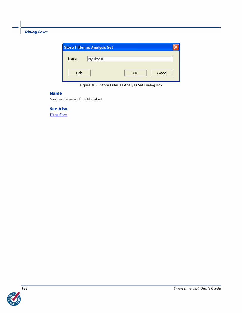
Dialog Boxes
156 SmartTime v8.4 User’s Guide
Figure 109 · Store Filter as Analysis Set Dialog Box
Name Specifies the name of the filtered set.
See Also Using filters

Store Filter as Analysis Set Dialog Box
SmartTime v8.4 User’s Guide 157
Timing Bottleneck Analysis Options Dialog Box Use this dialog box to customize the timing bottleneck report.
You can set report bottleneck options for the following categories:
• General pane
• Bottleneck pane
• Sets pane
To open the Timing Bottleneck Analysis Options dialog box (shown below) from the SmartTime tool,
choose Tools > Timing Analyzer > Bottleneck Analysis.
General Pane
Figure 110 · Timing Bottleneck Report - General Pane Dialog Box
Analysis Lets you specify what type of analysis will be reported in the report. By default, the report includes Maximum
Delay Analysis.
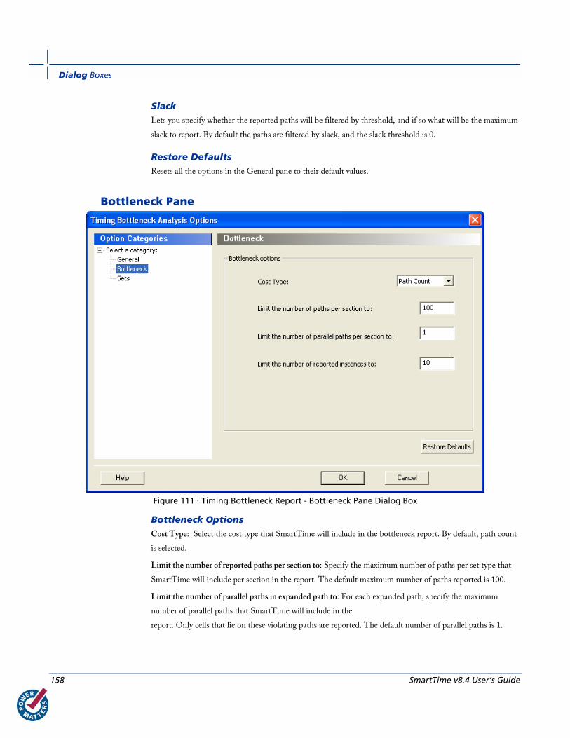
Dialog Boxes
158 SmartTime v8.4 User’s Guide
Slack Lets you specify whether the reported paths will be filtered by threshold, and if so what will be the maximum
slack to report. By default the paths are filtered by slack, and the slack threshold is 0.
Restore Defaults Resets all the options in the General pane to their default values.
Bottleneck Pane
Figure 111 · Timing Bottleneck Report - Bottleneck Pane Dialog Box
Bottleneck Options Cost Type: Select the cost type that SmartTime will include in the bottleneck report. By default, path count
is selected.
Limit the number of reported paths per section to: Specify the maximum number of paths per set type that
SmartTime will include per section in the report. The default maximum number of paths reported is 100.
Limit the number of parallel paths in expanded path to: For each expanded path, specify the maximum
number of parallel paths that SmartTime will include in the
report. Only cells that lie on these violating paths are reported. The default number of parallel paths is 1.

Store Filter as Analysis Set Dialog Box
SmartTime v8.4 User’s Guide 159
Limit the number of reported instances: Specify the maximum number of cells that SmartTime will include
per section in the report. The default number of cells is 10.
Restore Defaults Resets all the options in the Bottleneck panel to their default values.
Sets Pane
Figure 112 · Timing Bottleneck Report - Sets Pane Dialog Box
This pane has three mutually exclusive options:
• Entire Design
• Clock Domain
• Use existing user set
Entire Design: Select this option to display the bottleneck information for the entire design.
Clock Domain: Select this option to display the bottleneck information for the selected clock domain. You can specify
the following options:
• Clock: Allows pruning based on a given clock domains. Only cells that lie on these violating paths are reported.
• Type: This option can only be used in conjunction with -clock. The acceptable values are:

Dialog Boxes
160 SmartTime v8.4 User’s Guide
Value Description
Register to Register Paths between registers in the design
Asynchronous to Register Paths from asynchronous pins to registers
Register to Asynchronous Paths from registers to asynchronous pins
External Recovery The set of paths from inputs to asynchronous pins
External Removal The set of paths from inputs to asynchronous pins
External Setup Paths from input ports to register
External Hold Paths from input ports to register
Clock to Output Paths from registers to output ports
Use existing user set: Displays the bottleneck information for the existing user set selected. Only paths that lie within
the name set are will be considered towards the bottleneck report.
Filter: Allows you to filter the bottleneck report by the following options:
• From: Reports only cells that lie on violating paths that start at locations specified by this option.
• To: Reports only cells that lie on violating paths that end at locations specified by this option.
Filter defaults to all outputs.
Restore Defaults Resets all the options in the Paths panel to their default values.
See Also Performing a bottleneck analysis
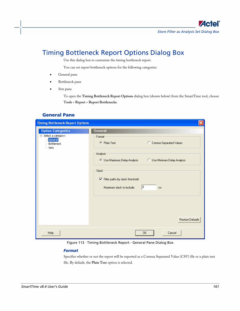
Store Filter as Analysis Set Dialog Box
SmartTime v8.4 User’s Guide 161
Timing Bottleneck Report Options Dialog Box Use this dialog box to customize the timing bottleneck report.
You can set report bottleneck options for the following categories:
• General pane
• Bottleneck pane
• Sets pane
To open the Timing Bottleneck Report Options dialog box (shown below) from the SmartTime tool, choose
Tools > Report > Report Bottlenecks.
General Pane
Figure 113 · Timing Bottleneck Report - General Pane Dialog Box
Format Specifies whether or not the report will be exported as a Comma Separated Value (CSV) file or a plain text
file. By default, the Plain Text option is selected.
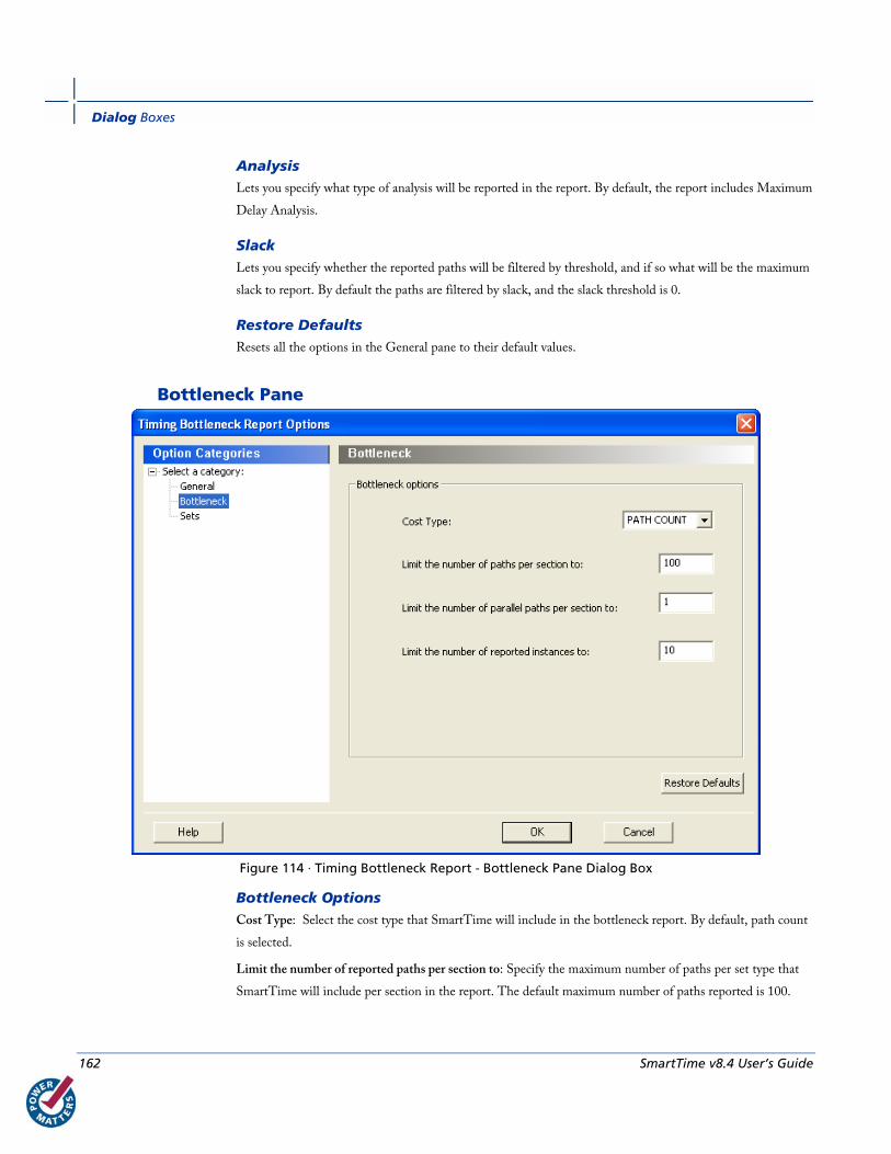
Dialog Boxes
162 SmartTime v8.4 User’s Guide
Analysis Lets you specify what type of analysis will be reported in the report. By default, the report includes Maximum
Delay Analysis.
Slack Lets you specify whether the reported paths will be filtered by threshold, and if so what will be the maximum
slack to report. By default the paths are filtered by slack, and the slack threshold is 0.
Restore Defaults Resets all the options in the General pane to their default values.
Bottleneck Pane
Figure 114 · Timing Bottleneck Report - Bottleneck Pane Dialog Box
Bottleneck Options Cost Type: Select the cost type that SmartTime will include in the bottleneck report. By default, path count
is selected.
Limit the number of reported paths per section to: Specify the maximum number of paths per set type that
SmartTime will include per section in the report. The default maximum number of paths reported is 100.
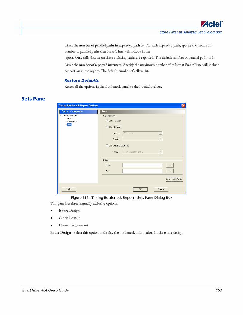
Store Filter as Analysis Set Dialog Box
SmartTime v8.4 User’s Guide 163
Limit the number of parallel paths in expanded path to: For each expanded path, specify the maximum
number of parallel paths that SmartTime will include in the
report. Only cells that lie on these violating paths are reported. The default number of parallel paths is 1.
Limit the number of reported instances: Specify the maximum number of cells that SmartTime will include
per section in the report. The default number of cells is 10.
Restore Defaults Resets all the options in the Bottleneck panel to their default values.
Sets Pane
Figure 115 · Timing Bottleneck Report - Sets Pane Dialog Box
This pane has three mutually exclusive options:
• Entire Design
• Clock Domain
• Use existing user set
Entire Design: Select this option to display the bottleneck information for the entire design.
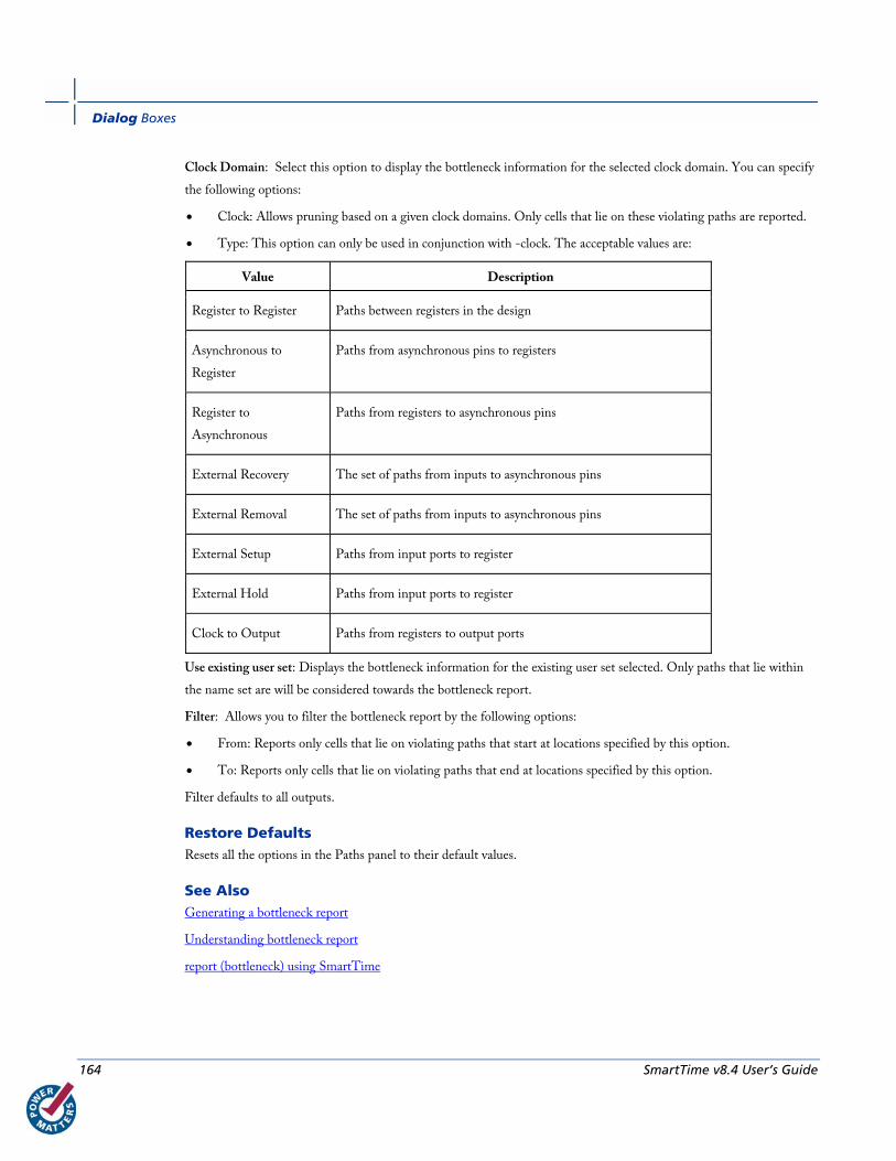
Dialog Boxes
164 SmartTime v8.4 User’s Guide
Clock Domain: Select this option to display the bottleneck information for the selected clock domain. You can specify
the following options:
• Clock: Allows pruning based on a given clock domains. Only cells that lie on these violating paths are reported.
• Type: This option can only be used in conjunction with -clock. The acceptable values are:
Value Description
Register to Register Paths between registers in the design
Asynchronous to
Register
Paths from asynchronous pins to registers
Register to
Asynchronous
Paths from registers to asynchronous pins
External Recovery The set of paths from inputs to asynchronous pins
External Removal The set of paths from inputs to asynchronous pins
External Setup Paths from input ports to register
External Hold Paths from input ports to register
Clock to Output Paths from registers to output ports
Use existing user set: Displays the bottleneck information for the existing user set selected. Only paths that lie within
the name set are will be considered towards the bottleneck report.
Filter: Allows you to filter the bottleneck report by the following options:
• From: Reports only cells that lie on violating paths that start at locations specified by this option.
• To: Reports only cells that lie on violating paths that end at locations specified by this option.
Filter defaults to all outputs.
Restore Defaults Resets all the options in the Paths panel to their default values.
See Also Generating a bottleneck report
Understanding bottleneck report
report (bottleneck) using SmartTime

Timing Datasheet Report Options Dialog Box
SmartTime v8.4 User’s Guide 165
Timing Datasheet Report Options Dialog Box Use this dialog box to select the output format for your timing datasheet report.
To open the Timing Datasheet Report Options dialog box (shown below) from the SmartTime tool, choose Tools >
Report > Report Datasheet.
You can generate your report in one of two formats:
Plain Text Select this option to save your report to disk in plain ASCII text format.
Comma Separated Values Select this option to save your report to disk in comma-separated value format (.CSV) format, which you can import
into a spreadsheet
Restore Defaults Resets the option to its default value, which is Plain Text.
See Also Generating a datasheet report
Understanding datasheet reports
report (Datasheet) using SmartTime
Timing Report Options Dialog Box Use this dialog box to customize the timing report.
You can set report options for the following categories:
• General
• Paths
• Sets
• Clock Domains
To open the Timing Report Options dialog box (shown below) from the SmartTime tool, choose Tools > Report >
Report Paths.
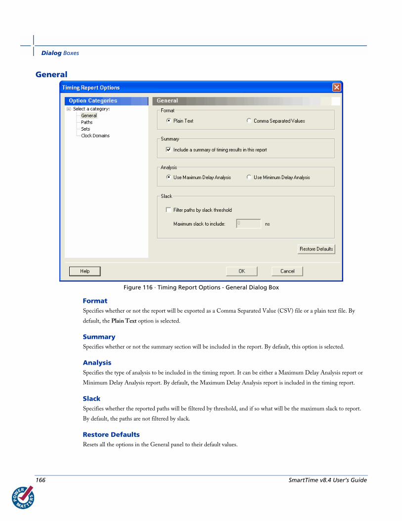
Dialog Boxes
166 SmartTime v8.4 User’s Guide
General
Figure 116 · Timing Report Options - General Dialog Box
Format Specifies whether or not the report will be exported as a Comma Separated Value (CSV) file or a plain text file. By
default, the Plain Text option is selected.
Summary Specifies whether or not the summary section will be included in the report. By default, this option is selected.
Analysis Specifies the type of analysis to be included in the timing report. It can be either a Maximum Delay Analysis report or
Minimum Delay Analysis report. By default, the Maximum Delay Analysis report is included in the timing report.
Slack Specifies whether the reported paths will be filtered by threshold, and if so what will be the maximum slack to report.
By default, the paths are not filtered by slack.
Restore Defaults Resets all the options in the General panel to their default values.
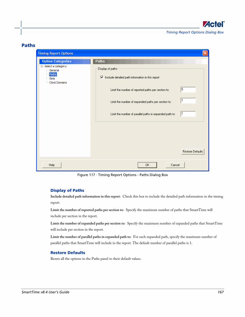
Timing Report Options Dialog Box
SmartTime v8.4 User’s Guide 167
Paths
Figure 117 · Timing Report Options - Paths Dialog Box
Display of Paths Include detailed path information in this report: Check this box to include the detailed path information in the timing
report.
Limit the number of reported paths per section to: Specify the maximum number of paths that SmartTime will
include per section in the report.
Limit the number of expanded paths per section to: Specify the maximum number of expanded paths that SmartTime
will include per section in the report.
Limit the number of parallel paths in expanded path to: For each expanded path, specify the maximum number of
parallel paths that SmartTime will include in the report. The default number of parallel paths is 1.
Restore Defaults Resets all the options in the Paths panel to their default values.

Dialog Boxes
168 SmartTime v8.4 User’s Guide
Sets
Figure 118 · Timing Report Options - Sets Dialog Box
Display of Sets Specifies whether or not the user sets will be included in the timing report.
User sets are either filters that you have created and stored on the default paths sets (Register to Register, Inputs to
Register, etc.) or Pin to Pin user sets. By default, the paths for these sets are not reported.
In addition, specify whether the Inputs to Output sets will be included in the report. By default, the Input to Output
sets are reported.
Restore Defaults Resets both options in the Sets panel to their default values.

Timing Report Options Dialog Box
SmartTime v8.4 User’s Guide 169
Clock Domains
Figure 119 · Timing Report Options - Clock Domains Dialog Box
Display of Clock Domains Lets you specify what clock domains will be included in the report. By default, the current clock domains used by the
timing engine will be reported.
Limit reporting on clock domains to specified domains Lets you include one or more of the clock domain names in the box, or include additional clock domain names using
Select Domains.
Restore Defaults Resets all options in the Clock Domains panel to their default values.
See Also Generating timing report
Understanding timing report
report (Timing) using SmartTime
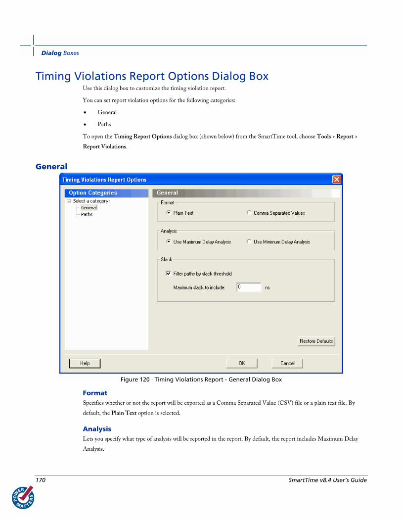
Dialog Boxes
170 SmartTime v8.4 User’s Guide
Timing Violations Report Options Dialog Box Use this dialog box to customize the timing violation report.
You can set report violation options for the following categories:
• General
• Paths
To open the Timing Report Options dialog box (shown below) from the SmartTime tool, choose Tools > Report >
Report Violations.
General
Figure 120 · Timing Violations Report - General Dialog Box
Format Specifies whether or not the report will be exported as a Comma Separated Value (CSV) file or a plain text file. By
default, the Plain Text option is selected.
Analysis Lets you specify what type of analysis will be reported in the report. By default, the report includes Maximum Delay
Analysis.
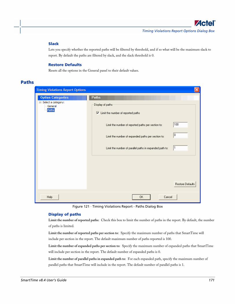
Timing Violations Report Options Dialog Box
SmartTime v8.4 User’s Guide 171
Slack Lets you specify whether the reported paths will be filtered by threshold, and if so what will be the maximum slack to
report. By default the paths are filtered by slack, and the slack threshold is 0.
Restore Defaults Resets all the options in the General panel to their default values.
Paths
Figure 121 · Timing Violations Report - Paths Dialog Box
Display of paths Limit the number of reported paths: Check this box to limit the number of paths in the report. By default, the number
of paths is limited.
Limit the number of reported paths per section to: Specify the maximum number of paths that SmartTime will
include per section in the report. The default maximum number of paths reported is 100.
Limit the number of expanded paths per section to: Specify the maximum number of expanded paths that SmartTime
will include per section in the report. The default number of expanded paths is 0.
Limit the number of parallel paths in expanded path to: For each expanded path, specify the maximum number of
parallel paths that SmartTime will include in the report. The default number of parallel paths is 1.

Dialog Boxes
172 SmartTime v8.4 User’s Guide
Restore Defaults Resets all the options in the Paths panel to their default values.
See Also Generating timing violation report
Understanding timing violation report
report (Timing violations) using SmartTime

SmartTime v8.4 User’s Guide 173
Menus, Tools, and Shortcut Keys
File Menu This menu is available in both Timing Constraint Editor View and Timing Analysis View.
Command Icon Shortcut Function
Commit
CTRL + S Saves changes to the working design for this Designer session only. Note:
To save changes to disk, you must also save your file in Designer.
Preview
Displays the active design in a Preview window
CTRL + P Displays the Print dialog box from which you can print your active design
Exit Closes SmartTime
Edit Menu This menu is available in both Timing Constraint Editor View and Timing Analysis View.
Command Icon Shortcut Function
Undo
CTRL + Z Reverses your last action
Redo
CTRL + Y Reverses the action of your last Undo command
Cut CTRL + X Removes the selection from your design
Copy
CTRL + C Copies the selection to the Clipboard
Paste
CTRL + V Pastes the selection from the Clipboard
Modify
Displays appropriate dialog box to edit the current constraint
Delete
Del Deletes the selected constraint
Select All CTRL + A Selects all logic in your design
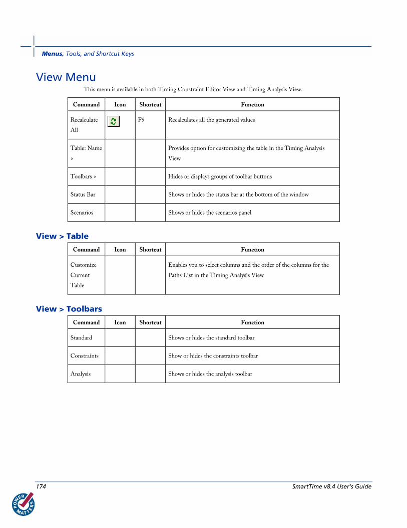
Menus, Tools, and Shortcut Keys
174 SmartTime v8.4 User’s Guide
View Menu This menu is available in both Timing Constraint Editor View and Timing Analysis View.
Command Icon Shortcut Function
Recalculate
All
F9 Recalculates all the generated values
Table: Name
>
Provides option for customizing the table in the Timing Analysis
View
Toolbars > Hides or displays groups of toolbar buttons
Status Bar Shows or hides the status bar at the bottom of the window
Scenarios Shows or hides the scenarios panel
View > Table
Command Icon Shortcut Function
Customize
Current
Table
Enables you to select columns and the order of the columns for the
Paths List in the Timing Analysis View
View > Toolbars
Command Icon Shortcut Function
Standard Shows or hides the standard toolbar
Constraints Show or hides the constraints toolbar
Analysis Shows or hides the analysis toolbar
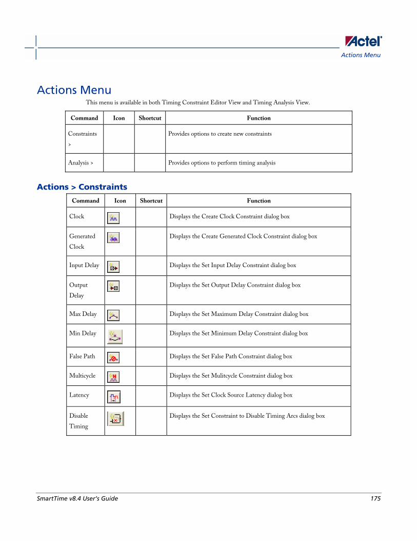
Actions Menu
SmartTime v8.4 User’s Guide 175
Actions Menu This menu is available in both Timing Constraint Editor View and Timing Analysis View.
Command Icon Shortcut Function
Constraints
>
Provides options to create new constraints
Analysis > Provides options to perform timing analysis
Actions > Constraints
Command Icon Shortcut Function
Clock
Displays the Create Clock Constraint dialog box
Generated
Clock
Displays the Create Generated Clock Constraint dialog box
Input Delay
Displays the Set Input Delay Constraint dialog box
Output
Delay
Displays the Set Output Delay Constraint dialog box
Max Delay
Displays the Set Maximum Delay Constraint dialog box
Min Delay
Displays the Set Minimum Delay Constraint dialog box
False Path
Displays the Set False Path Constraint dialog box
Multicycle
Displays the Set Mulitcycle Constraint dialog box
Latency
Displays the Set Clock Source Latency dialog box
Disable
Timing
Displays the Set Constraint to Disable Timing Arcs dialog box
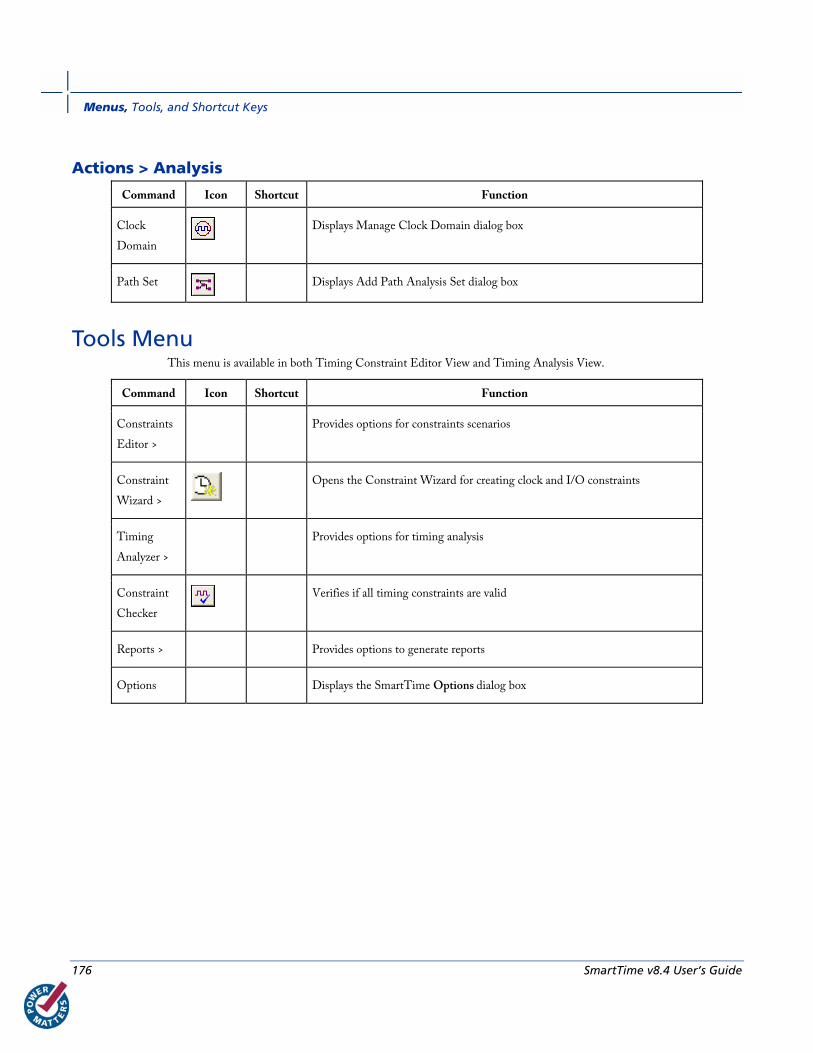
Menus, Tools, and Shortcut Keys
176 SmartTime v8.4 User’s Guide
Actions > Analysis
Command Icon Shortcut Function
Clock
Domain
Displays Manage Clock Domain dialog box
Path Set
Displays Add Path Analysis Set dialog box
Tools Menu This menu is available in both Timing Constraint Editor View and Timing Analysis View.
Command Icon Shortcut Function
Constraints
Editor >
Provides options for constraints scenarios
Constraint
Wizard >
Opens the Constraint Wizard for creating clock and I/O constraints
Timing
Analyzer >
Provides options for timing analysis
Constraint
Checker
Verifies if all timing constraints are valid
Reports > Provides options to generate reports
Options Displays the SmartTime Options dialog box
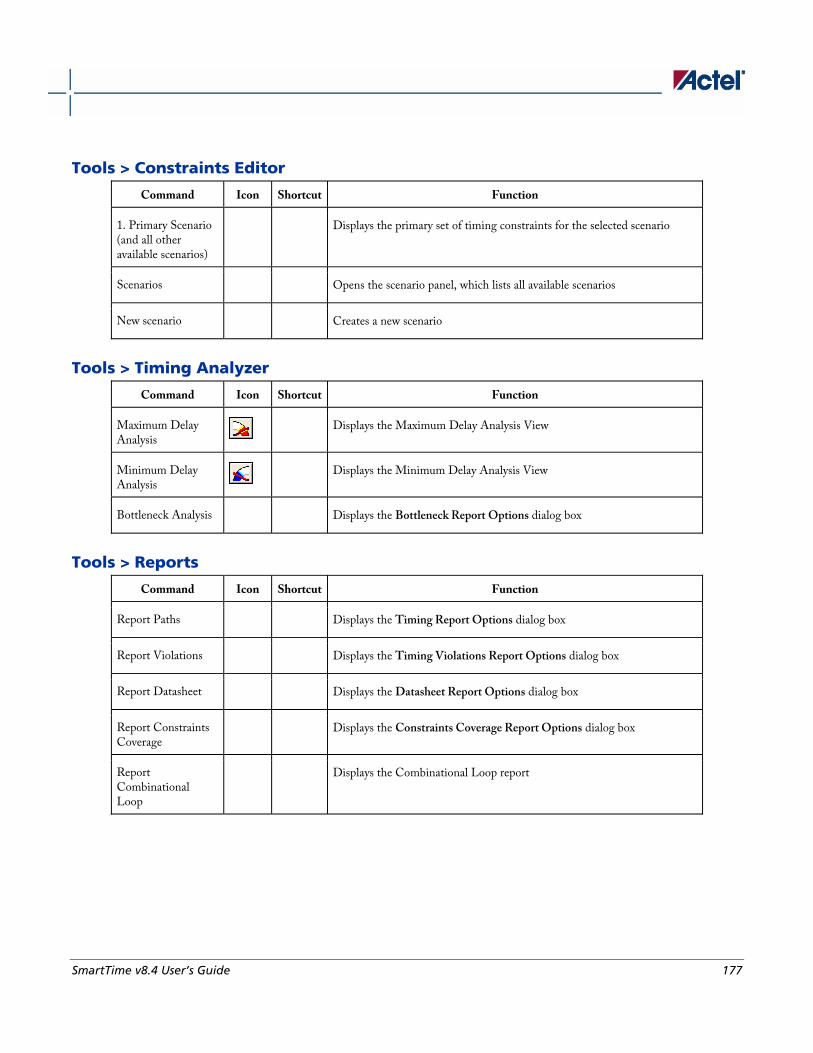
SmartTime v8.4 User’s Guide 177
Tools > Constraints Editor
Command Icon Shortcut Function
1. Primary Scenario (and all other available scenarios)
Displays the primary set of timing constraints for the selected scenario
Scenarios Opens the scenario panel, which lists all available scenarios
New scenario Creates a new scenario
Tools > Timing Analyzer
Command Icon Shortcut Function
Maximum Delay Analysis
Displays the Maximum Delay Analysis View
Minimum Delay Analysis
Displays the Minimum Delay Analysis View
Bottleneck Analysis Displays the Bottleneck Report Options dialog box
Tools > Reports
Command Icon Shortcut Function
Report Paths Displays the Timing Report Options dialog box
Report Violations Displays the Timing Violations Report Options dialog box
Report Datasheet Displays the Datasheet Report Options dialog box
Report Constraints Coverage
Displays the Constraints Coverage Report Options dialog box
Report Combinational Loop
Displays the Combinational Loop report

Menus, Tools, and Shortcut Keys
178 SmartTime v8.4 User’s Guide
Window Menu This menu is available in both Timing Constraint Editor View and Timing Analysis View.
Command Function
New Window Opens another window for the currently active tool Note: Use these
windows to view different parts of the design at the same time.
Cascade Arranges windows so you can see the title bar of each window
Tile Horizontally Arranges windows side-by-side in a horizontal pattern
Tile Vertically Arranges windows side-by-side in a vertical pattern
Minimize All Windows Minimizes all active windows
Arrange Icons Arranges minimized windows left-to-right across the bottom of the
Tool window
Close All Windows Closes all tool views
Help Menu This menu is available in both Timing Constraint Editor View and Timing Analysis View.
Command Function
Help Topics Displays the first Help topic for the SmartTime tool
SmartTime User's Guide Displays the SmartTime User's Guide
About SmartTime Displays the current version number and copyright information for the SmartTime
tool
Data Change History Displays features and enhancements, bug fixes and known issues for the current
software release that may impact timing data of the current design
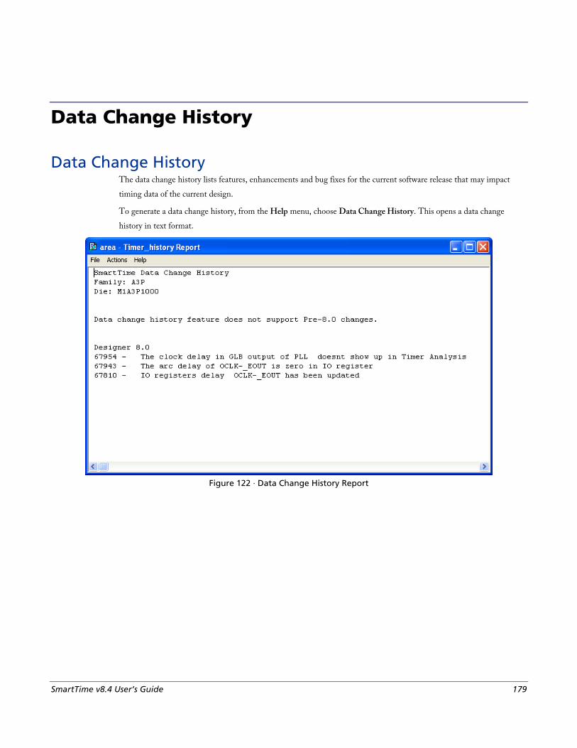
SmartTime v8.4 User’s Guide 179
Data Change History
Data Change History The data change history lists features, enhancements and bug fixes for the current software release that may impact
timing data of the current design.
To generate a data change history, from the Help menu, choose Data Change History. This opens a data change
history in text format.
Figure 122 · Data Change History Report
Data Change History
180 SmartTime v8.4 User’s Guide
all_inputs Returns an object representing all input and inout pins in the current design.
all_inputs
Arguments None
Supported Families IGLOO, Fusion, ProASIC3, ProASICPLUS, ProASIC, Axcelerator, RTAX-S, eX, and SX-A
Exceptions You can only use this command as part of a –from, -to, or –through argument in the following Tcl commands:
set_min_delay, set_max_delay, set_multicycle_path, and set_false_path.
Examples set_max_delay -from [all_inputs] -to [get_clocks ck1]
See Also Tcl documentation conventions
all_outputs Returns an object representing all output and inout pins in the current design.
all_outputs
Arguments None
Supported Families IGLOO, Fusion, ProASIC3, ProASICPLUS, ProASIC, Axcelerator, RTAX-S, eX, and SX-A
Exceptions You can only use this command as part of a –from, -to, or –through argument in the following Tcl commands:
4set_min_delay, set_max_delay, set_multicycle_path, and set_false_path.
Examples set_max_delay -from [all_inputs] -to [all_outputs]
all_registers
SmartTime v8.4 User’s Guide 181
See Also Tcl documentation conventions
all_registers Returns an object representing register pins or cells in the current scenario based on the given parameters.
all_registers [-clock clock_name] [-async_pins][-output_pins][-data_pins][-clock_pins]
Arguments -clock clock_name
Specifies the name of the clock domain to which the registers belong. If no clock is specified, all registers in the design will be targeted.
-async_pins
Lists all register pins that are async pins for the specified clock (or all registers asynchronous pins in the design).
-output_pins
Lists all register pins that are output pins for the specified clock (or all registers output pins in the design).
-data_pins
Lists all register pins that are data pins for the specified clock (or all registers data pins in the design).
-clock_pins
Lists all register pins that are data pins for the specified clock (or all registers clock pins in the design).
Supported Families IGLOO, Fusion, ProASIC3, ProASICPLUS, ProASIC, Axcelerator, RTAX-S, eX, and SX-A
Exceptions You can only use this command as part of a –from, -to, or –through argument in the following Tcl commands:
set_min_delay, set_max_delay, set_multicycle_path, and set_false_path.
Examples set_max_delay 2.000 -from { ff_m:CLK ff_s2:CLK } -to [all_registers -clock_pins -clock { ff_m:Q }]
See Also Tcl documentation conventions
Data Change History
182 SmartTime v8.4 User’s Guide
check_timing_constraints Checks all timing constraints in the current timing scenario for validity.
check_timing_constraints
Arguments None
Supported Families IGLOO, Fusion, ProASIC3, ProASICPLUS, ProASIC, Axcelerator, RTAX-S, eX, and SX-A
Exceptions None
Examples check_timing_constraints
See Also Tcl documentation conventions
clone_scenario Creates a new timing scenario by duplicating an existing one. You must provide a unique name (that is, it cannot
already be used by another timing scenario).
clone_scenario name -source origin
Arguments name
Specifies the name of the new timing scenario to create.
-source origin
Specifies the source of the timing scenario to clone (copy). The source must be a valid, existing timing scenario.
Supported Families IGLOO, Fusion, ProASIC3, Axcelerator, and RTAX-S
Description This command creates a timing scenario with the specified name, which includes a copy of all constraints in the
original scenario (specified with the -source parameter). The new scenario is then added to the list of scenarios.

create_clock
SmartTime v8.4 User’s Guide 183
Example clone_scenario scenario_A –source {Primary}
See Also create_scenario
delete_scenario
Tcl documentation conventions
create_clock Creates a clock constraint on the specified ports/pins, or a virtual clock if no source other than a name is specified.
create_clock -period period_value [-name clock_name] [-waveform> edge_list][source_objects]
Arguments -period period_value
Specifies the clock period in nanoseconds. The value you specify is the minimum time over which the clock waveform repeats. The period_value must be greater than zero.
-name clock_name
Specifies the name of the clock constraint. You must specify either a clock name or a source.
-waveform edge_list
Specifies the rise and fall times of the clock waveform in ns over a complete clock period. There must be exactly two transitions in the list, a rising transition followed by a falling transition. You can define a clock starting with a falling edge by providing an edge list where fall time is less than rise time. If you do not specify -waveform option, the tool creates a default waveform, with a rising edge at instant 0.0 ns and a falling edge at instant (period_value/2)ns.
source_objects
Specifies the source of the clock constraint. The source can be ports, pins, or nets in the design. If you specify a clock constraint on a pin that already has a clock, the new clock replaces the existing one. You must specify either a source or a clock name.
Supported Families IGLOO, Fusion, ProASIC3, ProASICPLUS, ProASIC (for analysis), Axcelerator, RTAX-S,eX, and SX-A
Description Creates a clock in the current design at the declared source and defines its period and waveform. The static timing
analysis tool uses this information to propagate the waveform across the clock network to the clock pins of all
sequential elements driven by this clock source.
The clock information is also used to compute the slacks in the specified clock domain that drive optimization tools
such as place-and-route.
Exceptions • None
Data Change History
184 SmartTime v8.4 User’s Guide
Examples The following example creates two clocks on ports CK1 and CK2 with a period of 6, a rising edge at 0, and a falling
edge at 3:
create_clock -name {my_user_clock} -period 6 CK1
create_clock -name {my_other_user_clock} –period 6 –waveform {0 3} {CK2}
The following example creates a clock on port CK3 with a period of 7, a rising edge at 2, and a falling edge at 4:
create_clock –period 7 –waveform {2 4} [get_ports {CK3}]
See Also create_generated_clock
Tcl Command Documentation Conventions
create_generated_clock Creates an internally generated clock constraint on the ports/pins and defines its characteristics.
create_generated_clock [-name name] -source reference_pin [-divide_by divide_factor] [-multiply_by multiply_factor] [-invert] source
Arguments -name name
Specifies the name of the clock constraint.
-source reference_pin
Specifies the reference pin in the design from which the clock waveform is to be derived.
-divide_by divide_factor
Specifies the frequency division factor. For instance if the divide_factor is equal to 2, the generated clock period is twice the reference clock period.
-multiply_by multiply_factor
Specifies the frequency multiplication factor. For instance if the multiply_factor is equal to 2, the generated clock period is half the reference clock period.
-invert
Specifies that the generated clock waveform is inverted with respect to the reference clock.
source
Specifies the source of the clock constraint on internal pins of the design. If you specify a clock constraint on a pin that already has a clock, the new clock replaces the existing clock. Only one source is accepted. Wildcards are accepted as long as the resolution shows one pin.
Supported Families IGLOO, Fusion, ProASIC3, ProASICPLUS, ProASIC (for analysis), Axcelerator, RTAX-S,eX, and SX-A
create_scenario
SmartTime v8.4 User’s Guide 185
Description Creates a generated clock in the current design at a declared source by defining its frequency with respect to the
frequency at the reference pin. The static timing analysis tool uses this information to compute and propagate its
waveform across the clock network to the clock pins of all sequential elements driven by this source.
The generated clock information is also used to compute the slacks in the specified clock domain that drive
optimization tools such as place-and-route.
Examples The following example creates a generated clock on pin U1/reg1:Q with a period twice as long as the period at the
reference port CLK.
create_generated_clock -name {my_user_clock} –divide_by 2 –source [get_ports {CLK}] U1/reg1:Q
The following example creates a generated clock at the primary output of myPLL with a period ¾ of the period at the
reference pin clk.
create_generated_clock –divide_by 3 –multiply_by 4 -source clk [get_pins {myPLL:CLK1}]
See Also create_clock
Tcl Command Documentation Conventions
create_scenario Creates a new timing scenario with the specified name. You must provide a unique name (that is, it cannot already be
used by another timing scenario).
create_scenario name
Arguments name
Specifies the name of the new timing scenario.
Supported Families IGLOO, Fusion, ProASIC3, Axcelerator, and RTAX-S
Description A timing scenario is a set of timing constraints used with a design. Scenarios enable you to easily refine the set of
timing constraints used for Timing-Driven Place-and-Route, so as to achieve timing closure more rapidly.
This command creates an empty timing scenario with the specified name and adds it to the list of scenarios.
Data Change History
186 SmartTime v8.4 User’s Guide
Exceptions • None
Example create_scenario scenario_A
See Also clone_scenario
Tcl Command Documentation Conventions
delete_scenario Deletes the specified timing scenario.
delete_scenario name
Arguments name
Specifies the name of the timing scenario to delete.
Supported Families IGLOO, Fusion, ProASIC3, Axcelerator, and RTAX-S
Description This command deletes the specified timing scenario and all the constraints it contains.
Exceptions • At least one timing scenario must always be available. If the current scenario is the only one that exists, you
cannot delete it.
• Scenarios that are linked to the timing analysis or layout cannot be deleted.
Example delete_scenario scenario_A
See Also create_scenario
Tcl Command Documentation Conventions
get_cells
SmartTime v8.4 User’s Guide 187
get_cells Returns an object representing the cells (instances) that match those specified in the pattern argument.
get_cells pattern
Arguments pattern
Specifies the pattern to match the instances to return. For example, "get_cells U18*" returns all instances starting with the characters "U18", where “*” is a wildcard that represents any character string.
Supported Families IGLOO, Fusion, ProASIC3, ProASICPLUS, ProASIC, Axcelerator, RTAX-S, eX, and SX-A
Description This command returns a collection of instances matching the pattern you specify. You can only use this command as
part of a –from, -to, or –through argument in the following Tcl commands: set_max delay, set_multicycle_path, and
set_false_path.
Exceptions • None
Examples set_max_delay 2 -from [get_cells {reg*}] -to [get_ports {out}]
set_false_path –through [get_cells {Rblock/muxA}]
See Also get_clocks
get_nets
get_pins
get_ports
Tcl Command Documentation Conventions
get_clocks Returns an object representing the clock(s) that match those specified in the pattern argument in the current timing
scenario.
get_clocks pattern
Arguments pattern
Data Change History
188 SmartTime v8.4 User’s Guide
Specifies the pattern to use to match the clocks set in SmartTime or Timer.
Supported Families IGLOO, Fusion, ProASIC3, ProASICPLUS, ProASIC, Axcelerator, RTAX-S, eX, and SX-A
Description • If this command is used as a –from argument in either the set maximum (set_max_delay), or set minimum delay
(set_min_delay), false path (set_false_path), and multicycle constraints (set_multicycle_path), the clock pins of
all the registers related to this clock are used as path start points.
• If this command is used as a –to argument in either the set maximum (set_max_delay), or set minimum delay
(set_min_delay), false path (set_false_path), and multicycle constraints (set_multicycle_path), the synchronous
pins of all the registers related to this clock are used as path endpoints.
Exceptions • None
Example set_max_delay -from [get_ports datal] -to \ [get_clocks ck1]
See Also create_clock
create_generated_clock
Tcl Command Documentation Conventions
get_current_scenario Returns the name of the current timing scenario.
get_current_scenario
Arguments None
Supported Families IGLOO, Fusion, ProASIC3, Axcelerator, and RTAX-S
Exceptions None
get_nets
SmartTime v8.4 User’s Guide 189
Examples get_current_scenario
See Also set_current_scenario
Tcl documentation conventions
get_nets Returns an object representing the nets that match those specified in the pattern argument.
get_nets pattern
Arguments pattern
Specifies the pattern to match the names of the nets to return. For example, "get_nets N_255*" returns all nets starting with the characters "N_255", where “*” is a wildcard that represents any character string.
Supported Families IGLOO, Fusion, ProASIC3, ProASICPLUS, ProASIC, Axcelerator, RTAX-S, eX, and SX-A
Description This command returns a collection of nets matching the pattern you specify. You can only use this command as source
objects in create clock (create_clock) or create generated clock (create_generated_clock) constraints and as -through
arguments in the set false path, set minimum delay, set maximum delay, and set multicycle path constraints.
Exceptions • None
Examples set_max_delay 2 -from [get_ports RDATA1] -through [get_nets {net_chkp1 net_chkqi}]
set_false_path –through [get_nets {Tblk/rm/n*}]
create_clock -name mainCLK -period 2.5 [get_nets {cknet}]
See Also create_clock
create_generated_clock
set_false_path
set_min_delay
set_max_delay
set_multicycle_path
Tcl documentation conventions
Data Change History
190 SmartTime v8.4 User’s Guide
get_pins Returns an object representing the pin(s) that match those specified in the pattern argument.
get_pins pattern
Arguments pattern
Specifies the pattern to match the pins to return. For example, "get_pins clock_gen*" returns all pins starting with the characters "clock_gen", where “*” is a wildcard that represents any character string.
Supported Families IGLOO, Fusion, ProASIC3, ProASICPLUS, ProASIC, Axcelerator, RTAX-S, eX, and SX-A
Exceptions • None
Example create_clock -period 10 [get_pins clock_gen/reg2:Q]
See Also create_clock
create_generated_clock
set_clock_latency
set_false_path
set_min_delay
set_max_delay
set_multicycle_path
Tcl documentation conventions
get_ports Returns an object representing the port(s) that match those specified in the pattern argument.
get_portspattern
Argument pattern
Specifies the pattern to match the ports.
Supported Families IGLOO, Fusion, ProASIC3, ProASICPLUS, ProASIC, Axcelerator, RTAX-S, eX, and SX-A
list_disable_timings
SmartTime v8.4 User’s Guide 191
Exceptions • None
Example create_clock -period 10 [get_ports CK1]
See Also create_clock
set_clock_latency
set_input_delay
set_output_delay
set_min_delay
set_max_delay
set_false_path
set_multicycle_path
Tcl documentation conventions
list_disable_timings Returns the list of disable timing constraints for the current scenario.
list_disable_timings
Arguments
• None
Supported Families
IGLOO, Fusion, ProASIC3, Axcelerator, and RTAX-S
Exceptions • None
Example list_disable_timings
list_objects Returns a list of names of the objects in the specified list.
list_scenarios <object_list>
Arguments None
Data Change History
192 SmartTime v8.4 User’s Guide
Supported Families All
Exceptions None
Examples list_objects <object_list>
See Also Tcl documentation conventions
list_scenarios Returns a list of names of all of the available timing scenarios.
list_scenarios
Arguments None
Supported Families IGLOO, Fusion, ProASIC3, ProASICPLUS, ProASIC, Axcelerator, RTAX-S, eX, and SX-A
Exceptions None
Examples list_scenarios
See Also get_current_scenario
Tcl documentation conventions
remove_clock Removes the specified clock constraint from the current timing scenario.
remove_clock {-name clock_name| -id constraint_ID
Arguments -name clock_name
remove_clock_latency
SmartTime v8.4 User’s Guide 193
Specifies the name of the clock constraint to remove from the current scenario. You must specify either a clock name or an ID.
-id constraint_ID
Specifies the ID of the clock constraint to remove from the current scenario. You must specify either an ID or a clock name that exists in the current scenario.
Supported Families IGLOO, Fusion, ProASIC3, ProASICPLUS, ProASIC (for analysis), Axcelerator, RTAX-S,eX, and SX-A
Description Removes the specified clock constraint from the current scenario. If the specified name does not match a clock
constraint in the current scenario, or if the specified ID does not refer to a clock constraint, this command fails.
Do not specify both the name and the ID.
Exceptions • You cannot use wildcards when specifying a clock name.
Examples The following example removes the clock constraint named "my_user_clock":
remove_clock -name my_user_clock
The following example removes the clock constraint using its ID:
set clockId [create_clock –name my_user_clock –period 2]
remove_clock –id $clockId
See Also create_clock
Tcl Command Documentation Conventions
remove_clock_latency Removes a clock source latency from the specified clock and from all edges of the clock.
remove_clock_latency {-source clock_name_or_source |-id constraint_ID}
Arguments -source clock_name_or_source
Specifies either the clock name or source name of the clock constraint from which to remove the clock source latency. You must specify either a clock or source name or its constraint ID.
-id constraint_ID
Specifies the ID of the clock constraint to remove from the current scenario. You must specify either a clock or source name or its constraint ID.

Data Change History
194 SmartTime v8.4 User’s Guide
Supported Families IGLOO, Fusion, ProASIC3, ProASICPLUS, ProASIC (for analysis), Axcelerator, RTAX-S,eX, and SX-A
Description Removes a clock source latency from the specified clock in the current scenario. If the specified source does not match a
clock with a latency constraint in the current scenario, or if the specified ID does not refer to a clock with a latency
constraint, this command fails.
Do not specify both the source and the ID.
Exceptions • You cannot use wildcards when specifying a clock name.
Examples The following example removes the clock source latency from the specified clock.
remove_clock_latency -source my_clock
See Also set_clock_latency
Tcl Command Documentation Conventions
remove_disable_timing Removes a disable timing constraint by specifying its arguments, or its ID. If the arguments do not match a disable
timing constraint, or if the ID does not refer to a disable timing constraint, the command fails.
remove_disable_timing -from value -to value name -id name
Arguments -from from_port
Specifies the starting port. The –from and –to arguments must either both be present or both omitted for the constraint to be valid.
-to to_port
Specifies the ending port. The –from and –to arguments must either both be present or both omitted for the constraint to be valid.
name
Specifies the cell name where the disable timing constraint will be removed. It is an error to supply both a cell name and a constraint ID, as they are mutually exclusive. No wildcards are allowed when specifying a clock name, either alone or in an accessor command1.
-id name
Specifies the constraint name where the disable timing constraint will be removed. It is an error to supply both a cell name and a constraint ID, as they are mutually exclusive. No wildcards are allowed when specifying a clock name, either alone or in an accessor command1.
remove_false_path
SmartTime v8.4 User’s Guide 195
Supported Families IGLOO, Fusion, ProASIC3, Axcelerator, and RTAX-S
Exceptions • None
Example remove_disable_timing -from port1 -to port2 -id new_constraint
remove_false_path Removes a false path from the current timing scenario by specifying either its exact arguments or its ID.
remove_false_path [-from from_list] [-to to_list] [-through through_list] [-id constraint_ID]
remove_false_path -id constraint_ID
Arguments -from from_list
Specifies a list of timing path starting points. A valid timing starting point is a clock, a primary input, an inout port, or a clock pin of a sequential cell.
-through through_list
Specifies a list of pins, ports, cells, or nets through which the disabled paths must pass.
-to to_list
Specifies a list of timing path ending points. A valid timing ending point is a clock, a primary output, an inout port, or a data pin of a sequential cell.
-id constraint_ID
Specifies the ID of the false path constraint to remove from the current scenario. You must specify either the exact false path to remove or the constraint ID that refers to the false path constraint to remove.
Supported Families IGLOO, Fusion, ProASIC3, ProASICPLUS, ProASIC (for analysis), Axcelerator, RTAX-S, eX (-through option), and
SX-A (-through option)
Description Removes a false path from the specified clock in the current scenario. If the arguments do not match a false path
constraint in the current scenario, or if the specified ID does not refer to a false path constraint, this command fails.
Do not specify both the false path arguments and the constraint ID.
Exceptions • You cannot use wildcards when specifying a clock name, either alone or in an Accessor command such as
get_pins or get_ports.
Data Change History
196 SmartTime v8.4 User’s Guide
Examples The following example specifies all false paths to remove:
remove_false_path -through U0/U1:Y
The following example removes the false path constraint using its id:
set fpId [set_false_path –from [get_clocks c*] –through {topx/reg/*} –to [get_ports out15] ]
remove_false_path –id $fpId
See Also set_false_path
Tcl Command Documentation Conventions
remove_generated_clock Removes the specified generated clock constraint from the current scenario.
remove_generated_clock {-name clock_name | -id constraint_ID }
Arguments -name clock_name
Specifies the name of the generated clock constraint to remove from the current scenario. You must specify either a clock name or an ID.
-id constraint_ID
Specifies the ID of the generated clock constraint to remove from the current scenario. You must specify either an ID or a clock name that exists in the current scenario.
Supported Families IGLOO, Fusion, ProASIC3, ProASICPLUS, ProASIC (for analysis), Axcelerator, RTAX-S,eX, and SX-A
Description Removes the specified generated clock constraint from the current scenario. If the specified name does not match a
generated clock constraint in the current scenario, or if the specified ID does not refer to a generated clock constraint,
this command fails.
Do not specify both the name and the ID.
Exceptions • You cannot use wildcards when specifying a generated clock name.
Examples The following example removes the generated clock constraint named "my_user_clock":
remove_generated_clock -name my_user_clock

remove_input_delay
SmartTime v8.4 User’s Guide 197
See Also create_generated_clock
Tcl Command Documentation Conventions
remove_input_delay Removes an input delay a clock on a port by specifying both the clocks and port names or the ID of the input_delay
constraint to remove.
remove_input_delay -clock clock_name port_pin_list
remove_input_delay -id constraint_ID
Arguments -clock clock_name
Specifies the clock name to which the specified input delay value is assigned.
port_pin_list
Specifies the port names to which the specified input delay value is assigned.
-id constraint_ID
Specifies the ID of the clock with the input_delay value to remove from the current scenario. You must specify either both a clock name and list of port names or the input_delay constraint ID .
Supported Families IGLOO, Fusion, ProASIC3, ProASICPLUS, ProASIC, Axcelerator, RTAX-S, eX (for analysis), and SX-A (for
analysis)
Description Removes an input delay from the specified clocks and port in the current scenario. If the clocks and port names do not
match an input delay constraint in the current scenario, or if the specified ID does not refer to an input delay
constraint, this command fails.
Do not specify both the clock and port names and the constraint ID.
Exceptions • You cannot use wildcards when specifying a clock name, either alone or in an accessor command.
Examples The following example removes the input delay from CLK1 on port data1:
remove_input_delay -clock [get_clocks CLK1] [get_ports data1]
See Also set_input_delay
Tcl Command Documentation Conventions

Data Change History
198 SmartTime v8.4 User’s Guide
remove_max_delay Removes a maximum delay constraint from the current timing scenario by specifying either its exact arguments or its
ID.
remove_max_delay [-from from_list] [-to to_list] [-through through_list]
remove_max_delay -id constraint_ID
Arguments -from from_list
Specifies a list of timing path starting points. A valid timing starting point is a clock, a primary input, an inout port, or a clock pin of a sequential cell.
-through through_list
Specifies a list of pins, ports, cells, or nets through which the disabled paths must pass.
-to to_list
Specifies a list of timing path ending points. A valid timing ending point is a clock, a primary output, an inout port, or a data pin of a sequential cell.
-id constraint_ID
Specifies the ID of the maximum delay constraint to remove from the current scenario. You must specify either the exact maximum delay arguments to remove or the constraint ID that refers to the maximum delay constraint to remove.
Supported Families IGLOO, Fusion, ProASIC3, ProASICPLUS, ProASIC (for analysis), Axcelerator, RTAX-S, eX (-through option), and
SX-A (-through option)
Description Removes a maximum delay value from the specified clock in the current scenario. If the arguments do not match a
maximum delay constraint in the current scenario, or if the specified ID does not refer to a maximum delay constraint,
this command fails.
Do not specify both the maximum delay arguments and the constraint ID.
Exceptions • You cannot use wildcards when specifying a clock name, either alone or in an Accessor command.
Examples The following example specifies a range of maximum delay constraints to remove:
remove_max_delay -through U0/U1:Y
See Also set_max_delay
Tcl Command Documentation Conventions
remove_min_delay
SmartTime v8.4 User’s Guide 199
remove_min_delay Removes a minimum delay constraint in the current timing scenario by specifying either its exact arguments or its ID.
remove_min_delay [-from from_list] [-to to_list] [-through through_list]
remove_min_delay -id constraint_ID
Arguments -from from_list
Specifies a list of timing path starting points. A valid timing starting point is a clock, a primary input, an inout port, or a clock pin of a sequential cell.
-through through_list
Specifies a list of pins, ports, cells, or nets through which the disabled paths must pass.
-toto_list
Specifies a list of timing path ending points. A valid timing ending point is a clock, a primary output, an inout port, or a data pin of a sequential cell.
-id constraint_ID
Specifies the ID of the minimum delay constraint to remove from the current scenario. You must specify either the exact minimum delay arguments to remove or the constraint ID that refers to the minimum delay constraint to remove.
Supported Families IGLOO, Fusion, ProASIC3, ProASICPLUS, ProASIC (for analysis), Axcelerator, RTAX-S, eX (-through option), and
SX-A (-through option)
Description Removes a minimum delay value from the specified clock in the current scenario. If the arguments do not match a
minimum delay constraint in the current scenario, or if the specified ID does not refer to a minimum delay constraint,
this command fails.
Do not specify both the minimum delay arguments and the constraint ID.
Exceptions • You cannot use wildcards when specifying a clock name, either alone or in an accessor command.
Examples The following example specifies a range of minimum delay constraints to remove:
remove_min_delay -through U0/U1:Y
See Also set_min_delay
Tcl Command Documentation Conventions
Data Change History
200 SmartTime v8.4 User’s Guide
remove_multicycle_path Removes a multicycle path constraint in the current timing scenario by specifying either its exact arguments or its ID.
remove_multicycle_path [-from from_list] [-to to_list] [-through through_list]
remove multicycle_path -id constraint_ID
Arguments -from from_list
Specifies a list of timing path starting points. A valid timing starting point is a clock, a primary input, an inout port, or a clock pin of a sequential cell.
-through through_list
Specifies a list of pins, ports, cells, or nets through which the disabled paths must pass.
-toto_list
Specifies a list of timing path ending points. A valid timing ending point is a clock, a primary output, an inout port, or a data pin of a sequential cell.
-id constraint_ID
Specifies the ID of the multicycle path constraint to remove from the current scenario. You must specify either the exact multicycle path arguments to remove or the constraint ID that refers to the multicycle path constraint to remove.
Supported Families IGLOO, Fusion, ProASIC3, ProASICPLUS, ProASIC (for analysis), Axcelerator, RTAX-S, eX (for analysis), SX-A
(for analysis)
Description Removes a multicycle path from the specified clock in the current scenario. If the arguments do not match a multicycle
path constraint in the current scenario, or if the specified ID does not refer to a multicycle path constraint, this
command fails.
Do not specify both the multicycle path arguments and the constraint ID.
Exceptions • You cannot use wildcards when specifying a clock name, either alone or in an accessor command.
Examples The following example removes all paths between reg1 and reg2 to 3 cycles for setup check.
remove_multicycle_path -from [get_pins {reg1}] –to [get_pins {reg2}]
See Also set_multicycle_path
Tcl Command Documentation Conventions
remove_output_delay
SmartTime v8.4 User’s Guide 201
remove_output_delay Removes an ouput delay by specifying both the clocks and port names or the ID of the output_delay constraint to
remove.
remove_output_delay -clock clock_name port_pin_list
remove_output_delay -id constraint_ID
Arguments -clock clock_name
Specifies the clock name to which the specified output delay value is assigned.
port_pin_list
Specifies the port names to which the specified output delay value is assigned.
-id constraint_ID
Specifies the ID of the clock with the output_delay value to remove from the current scenario. You must specify either both a clock name and list of port names or the output_delay constraint ID .
Supported Families IGLOO, Fusion, ProASIC3, ProASICPLUS, ProASIC (for analysis), Axcelerator, RTAX-S, eX (for analysis), SX-A
(for analysis)
Description Removes an output delay from the specified clocks and port in the current scenario. If the clocks and port names do not
match an output delay constraint in the current scenario, or if the specified ID does not refer to an output delay
constraint, this command fails.
Do not specify both the clock and port names and the constraint ID.
Exceptions • You cannot use wildcards when specifying a clock name, either alone or in an accessor command.
Examples The following example removes the output delay from CLK1 on port out1:
remove_output_delay -clock [get_clocks CLK1] [get_ports out1]
See Also set_output_delay
Tcl Command Documentation Conventions

Data Change History
202 SmartTime v8.4 User’s Guide
rename_scenario Renames the specified timing scenario with the new name provided. You must provide a unique new name (that is, it
cannot already be used by another timing scenario).
rename_scenario oldname -new newname
Arguments oldname
Specifies the current name of the timing scenario.
-new newname
Specifies the new name to give to the timing scenario.
Supported Families IGLOO, Fusion, ProASIC3, Axcelerator, and RTAX-S
Description This command changes the name of the timing scenario in the list of scenarios.
Example rename_scenario scenario_A -new scenario_B
See Also create_scenario
delete_scenario
Tcl documentation conventions
set_clock_latency Defines the delay between an external clock source and the definition pin of a clock within SmartTime.
set_clock_latency -source [-rise][-fall][-early][-late] delay clock
Arguments -source
Specifies the source latency on a clock pin, potentially only on certain edges of the clock.
-rise
Specifies the edge for which this constraint will apply. If neither or both rise are passed, the same latency is applied to both edges.
-fall
Specifies the edge for which this constraint will apply. If neither or both rise are passed, the same latency is applied to both edges.
-invert
Specifies that the generated clock waveform is inverted with respect to the reference clock.
set_clock_latency
SmartTime v8.4 User’s Guide 203
-late
Optional. Specifies that the latency is late bound on the latency. The appropriate bound is used to provide the most pessimistic timing scenario. However, if the value of "-late" is less than the value of "-early", optimistic timing takes place which could result in incorrect analysis. If neither or both "-early" and "-late" are provided, the same latency is used for both bounds, which results in the latency having no effect for single clock domain setup and hold checks.
-early
Optional. Specifies that the latency is early bound on the latency. The appropriate bound is used to provide the most pessimistic timing scenario. However, if the value of "-late" is less than the value of "-early", optimistic timing takes place which could result in incorrect analysis. If neither or both "-early" and "-late" are provided, the same latency is used for both bounds, which results in the latency having no effect for single clock domain setup and hold checks.
delay
Specifies the latency value for the constraint.
clock
Specifies the clock to which the constraint is applied. This clock must be constrained.
Supported Families IGLOO, Fusion, ProASIC3, ProASICPLUS, ProASIC (for analysis), Axcelerator, RTAX-S,eX, and SX-A
Description Clock source latency defines the delay between an external clock source and the definition pin of a clock within
SmartTime. It behaves much like an input delay constraint. You can specify both an "early" delay and a"late" delay for
this latency, providing an uncertainty which SmartTime propagates through its calculations. Rising and falling edges of
the same clock can have different latencies. If only one value is provided for the clock source latency, it is taken as the
exact latency value, for both rising and falling edges.
Exceptions • None
Examples The following example sets an early clock source latency of 0.4 on the rising edge of main_clock. It also sets a clock
source latency of 1.2, for both the early and late values of the falling edge of main_clock. The late value for the clock
source latency for the falling edge of main_clock remains undefined.
set_clock_latency –source –rise –early 0.4 { main_clock }
set_clock_latency –source –fall 1.2 { main_clock }
See Also create_clock
create_generated_clock
Tcl Command Documentation Conventions
Data Change History
204 SmartTime v8.4 User’s Guide
set_current_scenario Specifies the timing scenario for the Timing Analyzer to use. All commands that follow this command will apply to the
specified timing scenario.
set_current_scenario name
Arguments name
Specifies the name of the timing scenario to which to apply all commands from this point on.
Supported Families IGLOO, Fusion, ProASIC3, Axcelerator, and RTAX-S
Description A timing scenario is a set of timing constraints used with a design. If the specified scenario is already the current one,
this command has no effect.
After setting the current scenario, constraints can be listed, added, or removed, the checker can be invoked on the set of
constraints, and so on.
This command uses the specified timing scenario to compute timing analysis.
Exceptions • None
Example set_current_scenario scenario_A
See Also get_current_scenario
Tcl Command Documentation Conventions
set_disable_timing Disables timing arcs within a cell and returns the ID of the created constraint if the command succeeded.
set_disable_timing -from value -to value name
Arguments -from from_port
Specifies the starting port. The –from and –to arguments must either both be present or both omitted for the constraint to be valid.
-to to_port
set_false_path (GCF)
SmartTime v8.4 User’s Guide 205
Specifies the ending port. The –from and –to arguments must either both be present or both omitted for the constraint to be valid.
name
Specifies the cell name where the timing arcs will be disabled.
Supported Families IGLOO, Fusion, ProASIC3, Axcelerator, and RTAX-S
Exceptions • None
Example set_disable_timing -from A -to Y a2
set_false_path (GCF) Defines false paths in the design; false paths are not considered in the timing driven place-and-route system.
set_false_path [-from from_port] [-through any_port] [-to to_port];
Arguments [-from from_port]
Must be an input port of the design or a register or memory instance output pin. You can use wildcards.
[-through any_port]
Must be an output port of the design or a register or memory instance input pin. You can use wildcards.
[-to to_port]
Must be any instance pin. You can use wildcards.
Supported Families ProASIC
Description • You must include at least one of the optional arguments.
Exceptions • None
Examples The following statement sets all paths starting from resetd which are going through instance const2 as false paths.
set_false_path -from resetd -through const2/*;
Data Change History
206 SmartTime v8.4 User’s Guide
See Also Constraint Support by Family
Constraint Entry Table
GCF Syntax Conventions
set_input_delay Creates an input delay on a port list by defining the arrival time of an input relative to a clock in the current scenario.
set_input_delay delay_value -clock clock_ref [–max] [–min] [–clock_fall] input_list
Arguments delay_value
Specifies the arrival time in nanoseconds that represents the amount of time for which the signal is available at the specified input after a clock edge.
-clock clock_ref
Specifies the clock reference to which the specified input delay is related. This is a mandatory argument. If you do not specify -max or -min options, the tool assumes the maximum and minimum input delays to be equal.
-max
Specifies that delay_value refers to the longest path arriving at the specified input. If you do not specify -max or -min options, the tool assumes maximum and minimum input delays to be equal.
-min
Specifies that delay_value refers to the shortest path arriving at the specified input. If you do not specify -max or -min options, the tool assumes maximum and minimum input delays to be equal.
-clock_fall
Specifies that the delay is relative to the falling edge of the clock reference. The default is the rising edge.
input_list
Provides a list of input ports in the current design to which delay_value is assigned. If you need to specify more than one object, enclose the objects in braces ({}).
Supported Families IGLOO, Fusion, ProASIC3, ProASICPLUS, ProASIC (for analysis), Axcelerator, RTAX-S, eX (for analysis), SX-A
(for analysis)
Description The set_input_delay command sets input path delays on input ports relative to a clock edge. This usually represents a
combinational path delay from the clock pin of a register external to the current design. For in/out (bidirectional) ports,
you can specify the path delays for both input and output modes. The tool adds input delay to path delay for paths
starting at primary inputs.
A clock is a singleton that represents the name of a defined clock constraint. This can be:
• a single port name used as source for a clock constraint
set_max_delay
SmartTime v8.4 User’s Guide 207
• a single pin name used as source for a clock constraint; for instance reg1:CLK. This name can be hierarchical (for
instance toplevel/block1/reg2:CLK)
• an object accessor that will refer to one clock: [get_clocks {clk}]
Examples The following example sets an input delay of 1.2ns for port data1 relative to the rising edge of CLK1:
set_input_delay 1.2 -clock [get_clocks CLK1] [get_ports data1]
The following example sets a different maximum and minimum input delay for port IN1 relative to the falling edge of
CLK2:
set_input_delay 1.0 -clock_fall -clock CLK2 –min {IN1}
set_input_delay 1.4 -clock_fall -clock CLK2 –max {IN1}
See Also set_output_delay
Tcl Command Documentation Conventions
set_max_delay Specifies the maximum delay for the timing paths in the current scenario.
set_max_delay delay_value [-from from_list] [-to to_list] [-through through_list]
Arguments delay_value
Specifies a floating point number in nanoseconds that represents the required maximum delay value for specified paths.
• If the path starting point is on a sequential device, the tool includes clock skew in the
computed delay.
• If the path starting point has an input delay specified, the tool adds that delay value to
the path delay.
• If the path ending point is on a sequential device, the tool includes clock skew and
library setup time in the computed delay.
• If the ending point has an output delay specified, the tool adds that delay to the path
delay.
-from from_list
Specifies a list of timing path starting points. A valid timing starting point is a clock, a primary input, an inout port, or a clock pin of a sequential cell.
-to to_list
Specifies a list of timing path ending points. A valid timing ending point is a clock, a primary output, an inout port, or a data pin of a sequential cell.
-through through_list
Data Change History
208 SmartTime v8.4 User’s Guide
Specifies a list of pins, ports, cells, or nets through which the timing paths must pass.
Supported Families IGLOO, Fusion, ProASIC3, ProASICPLUS, ProASIC (for analysis), Axcelerator, RTAX-S, eX (-through option), and
SX-A (-through option)
Description This command specifies the required maximum delay for timing paths in the current design. The path length for any
startpoint in from_list to any endpoint in to_list must be less than delay_value.
The timing engine automatically derives the individual maximum delay targets from clock waveforms and port input or
output delays.
The maximum delay constraint is a timing exception. This constraint overrides the default single cycle timing
relationship for one or more timing paths. This constraint also overrides a multicycle path constraint.
You must specify at least one of the –from, -to, or –through arguments for this constraint to be valid.
Examples The following example sets a maximum delay by constraining all paths from ff1a:CLK or ff1b:CLK to ff2e:D with a
delay less than 5 ns:
set_max_delay 5 -from {ff1a:CLK ff1b:CLK} -to {ff2e:D}
The following example sets a maximum delay by constraining all paths to output ports whose names start by “out” with
a delay less than 3.8 ns:
set_max_delay 3.8 -to [get_ports out*]
See Also set_min_delay
remove_max_delay
Tcl Command Documentation Conventions
set_min_delay Specifies the minimum delay for the timing paths in the current scenario.
set_min_delay delay_value [-from from_list] [-to to_list] [-through through_list]
Arguments delay_value
Specifies a floating point number in nanoseconds that represents the required minimum delay value for specified paths.
• If the path starting point is on a sequential device, the tool includes clock skew in the
computed delay.
set_min_delay
SmartTime v8.4 User’s Guide 209
• If the path starting point has an input delay specified, the tool adds that delay value to
the path delay.
• If the path ending point is on a sequential device, the tool includes clock skew and
library setup time in the computed delay.
• If the ending point has an output delay specified, the tool adds that delay to the path
delay.
-from from_list
Specifies a list of timing path starting points. A valid timing starting point is a clock, a primary input, an inout port, or a clock pin of a sequential cell.
-to to_list
Specifies a list of timing path ending points. A valid timing ending point is a clock, a primary output, an inout port, or a data pin of a sequential cell.
-through through_list
Specifies a list of pins, ports, cells, or nets through which the timing paths must pass.
Supported Families IGLOO, Fusion, ProASIC3, ProASICPLUS, ProASIC (for analysis), Axcelerator, RTAX-S, eX (-through option), and
SX-A (-through option)
Description This command specifies the required minimum delay for timing paths in the current design. The path length for any
startpoint in from_list to any endpoint in to_list must be less than delay_value.
The timing engine automatically derives the individual minimum delay targets from clock waveforms and port input or
output delays.
The minimum delay constraint is a timing exception. This constraint overrides the default single cycle timing
relationship for one or more timing paths. This constraint also overrides a multicycle path constraint.
You must specify at least one of the –from, -to, or –through arguments for this constraint to be valid.
Examples The following example sets a minimum delay by constraining all paths from ff1a:CLK or ff1b:CLK to ff2e:D with a
delay less than 5 ns:
set_min_delay 5 -from {ff1a:CLK ff1b:CLK} -to {ff2e:D}
The following example sets a minimum delay by constraining all paths to output ports whose names start by “out” with
a delay less than 3.8 ns:
set_min_delay 3.8 -to [get_ports out*]
See Also set_max_delay
remove_min_delay
Data Change History
210 SmartTime v8.4 User’s Guide
Tcl Command Documentation Conventions
set_multicycle_path Defines a path that takes multiple clock cycles in the current scenario.
set_multicycle_path ncycles [-setup] [-hold] [-from from_list[–through through_list[-to to_list
Arguments ncycles
Specifies an integer value that represents a number of cycles the data path must have for setup or hold check. The value is relative to the starting point or ending point clock, before data is required at the ending point.
-setup
Optional. Applies the cycle value for the setup check only. This option does not affect the hold check. The default hold check will be applied unless you have specified another set_multicycle_path command for the hold value.
-hold
Optional. Applies the cycle value for the hold check only. This option does not affect the setup check.
Note: If you do not specify "-setup" or "-hold", the cycle value is applied to the setup check and the default hold
check is performed (ncycles -1).
-from from_list
Specifies a list of timing path starting points. A valid timing starting point is a clock, a primary input, an inout port, or a clock pin of a sequential cell.
-through through_list
Specifies a list of pins or ports through which the multiple cycle paths must pass.
-to to_list
Specifies a list of timing path ending points. A valid timing ending point is a clock, a primary output, an inout port, or a data pin of a sequential cell.
Supported Families IGLOO, Fusion, ProASIC3, ProASICPLUS, ProASIC (for analysis), Axcelerator, RTAX-S, eX (for analysis), SX-A
(for analysis)
Description Setting multiple cycle paths constraint overrides the single cycle timing relationships between sequential elements by
specifying the number of cycles that the data path must have for setup or hold checks. If you change the multiplier, it
affects both the setup and hold checks.
False path information always takes precedence over multiple cycle path information. A specific maximum delay
constraint overrides a general multiple cycle path constraint.
If you specify more than one object within one -through option, the path passes through any of the objects.
You must specify at least one of the –from, -to, or –through arguments for this constraint to be valid.
set_output_delay
SmartTime v8.4 User’s Guide 211
Exceptions • Multiple priority management is not supported in Actel designs. All multiple cycle path constraints are handled
with the same priority.
Examples The following example sets all paths between reg1 and reg2 to 3 cycles for setup check. Hold check is measured at the
previous edge of the clock at reg2.
set_multicycle_path 3 -from [get_pins {reg1}] –to [get_pins {reg2}]
The following example specifies that four cycles are needed for setup check on all paths starting at the registers in the
clock domain ck1. Hold check is further specified with two cycles instead of the three cycles that would have been
applied otherwise.
set_multicycle_path 4 -setup -from [get_clocks {ck1}]
set_multicycle_path 2 -hold -from [get_clocks {ck1}]
See Also remove_multicycle_path
Tcl Command Documentation Conventions
set_output_delay Defines the output delay of an output relative to a clock in the current scenario.
set_output_delay delay_value -clock clock_ref [–max] [–min] [–clock_fall] output_list
Arguments delay_value
Specifies the amount of time before a clock edge for which the signal is required. This represents a combinational path delay to a register outside the current design plus the library setup time (for maximum output delay) or hold time (for minimum output delay).
-clock clock_ref
Specifies the clock reference to which the specified output delay is related. This is a mandatory argument. If you do not specify -max or -min options, the tool assumes the maximum and minimum input delays to be equal.
-max
Specifies that delay_value refers to the longest path from the specified output. If you do not specify -max or -min options, the tool assumes the maximum and minimum output delays to be equal.
-min
Specifies that delay_value refers to the shortest path from the specified output. If you do not specify -max or -min options, the tool assumes the maximum and minimum output delays to be equal.
-clock_fall
Specifies that the delay is relative to the falling edge of the clock reference. The default is the rising edge.
output_list
Provides a list of output ports in the current design to which delay_value is assigned. If you need to specify more than one object, enclose the objects in braces ({}).

Data Change History
212 SmartTime v8.4 User’s Guide
Supported Families IGLOO, Fusion, ProASIC3, ProASICPLUS, ProASIC (for analysis), Axcelerator, RTAX-S, eX (for analysis), SX-A
(for analysis)
Description The set_output_delay command sets output path delays on output ports relative to a clock edge. Output ports have no
output delay unless you specify it. For in/out (bidirectional) ports, you can specify the path delays for both input and
output modes. The tool adds output delay to path delay for paths ending at primary outputs.
Examples The following example sets an output delay of 1.2ns for port OUT1 relative to the rising edge of CLK1:
set_output_delay 1.2 -clock [get_clocks CLK1] [get_ports OUT1]
The following example sets a different maximum and minimum output delay for port OUT1 relative to the falling edge
of CLK2:
set_output_delay 1.0 -clock_fall -clock CLK2 –min {OUT1}
set_output_delay 1.4 -clock_fall -clock CLK2 –max {OUT1}
See Also remove_output_delay
set_input_delay
Tcl Command Documentation Conventions
st_commit Saves the changes made in SmartTime to the design (.adb) file
st_commit
Arguments None
Supported Families IGLOO, Fusion, ProASIC3, ProASICPLUS, ProASIC, and Axcelerator
Exceptions None
Examples st_commit
See Also st_restore
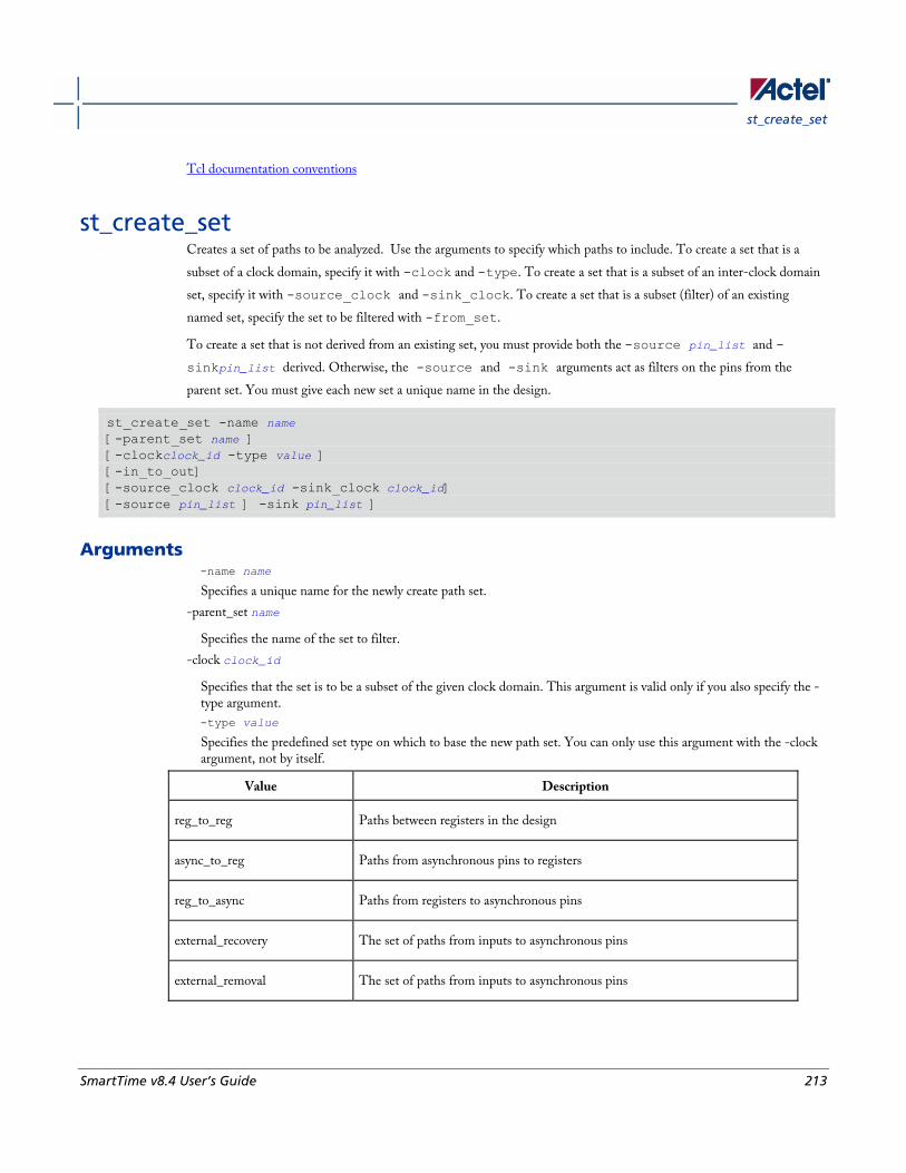
st_create_set
SmartTime v8.4 User’s Guide 213
Tcl documentation conventions
st_create_set Creates a set of paths to be analyzed. Use the arguments to specify which paths to include. To create a set that is a
subset of a clock domain, specify it with -clock and -type. To create a set that is a subset of an inter-clock domain
set, specify it with -source_clock and -sink_clock. To create a set that is a subset (filter) of an existing
named set, specify the set to be filtered with -from_set.
To create a set that is not derived from an existing set, you must provide both the -source pin_list and -
sinkpin_list derived. Otherwise, the -source and -sink arguments act as filters on the pins from the
parent set. You must give each new set a unique name in the design.
st_create_set -name name [-parent_set name ] [-clockclock_id -type value ] [-in_to_out] [-source_clock clock_id -sink_clock clock_id] [-source pin_list ] -sink pin_list ]
Arguments -name name
Specifies a unique name for the newly create path set.
-parent_set name
Specifies the name of the set to filter.
-clock clock_id
Specifies that the set is to be a subset of the given clock domain. This argument is valid only if you also specify the -type argument.
-type value
Specifies the predefined set type on which to base the new path set. You can only use this argument with the -clock argument, not by itself.
Value Description
reg_to_reg Paths between registers in the design
async_to_reg Paths from asynchronous pins to registers
reg_to_async Paths from registers to asynchronous pins
external_recovery The set of paths from inputs to asynchronous pins
external_removal The set of paths from inputs to asynchronous pins
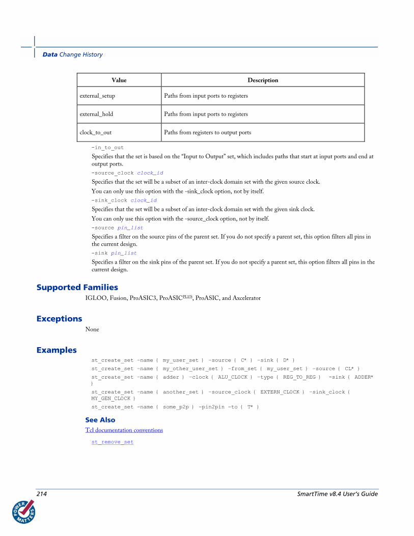
Data Change History
214 SmartTime v8.4 User’s Guide
Value Description
external_setup Paths from input ports to registers
external_hold Paths from input ports to registers
clock_to_out Paths from registers to output ports
-in_to_out
Specifies that the set is based on the “Input to Output” set, which includes paths that start at input ports and end at output ports.
-source_clock clock_id
Specifies that the set will be a subset of an inter-clock domain set with the given source clock.
You can only use this option with the -sink_clock option, not by itself.
-sink_clock clock_id
Specifies that the set will be a subset of an inter-clock domain set with the given sink clock.
You can only use this option with the -source_clock option, not by itself.
-source pin_list
Specifies a filter on the source pins of the parent set. If you do not specify a parent set, this option filters all pins in the current design.
-sink pin_list
Specifies a filter on the sink pins of the parent set. If you do not specify a parent set, this option filters all pins in the current design.
Supported Families IGLOO, Fusion, ProASIC3, ProASICPLUS, ProASIC, and Axcelerator
Exceptions None
Examples st_create_set –name { my_user_set } –source { C* } –sink { D* }
st_create_set –name { my_other_user_set } –from_set { my_user_set } –source { CL* }
st_create_set –name { adder } –clock { ALU_CLOCK } –type { REG_TO_REG } -sink { ADDER* }
st_create_set –name { another_set } –source_clock { EXTERN_CLOCK } –sink_clock { MY_GEN_CLOCK }
st_create_set –name { some_p2p } –pin2pin –to { T* }
See Also Tcl documentation conventions
st_remove_set
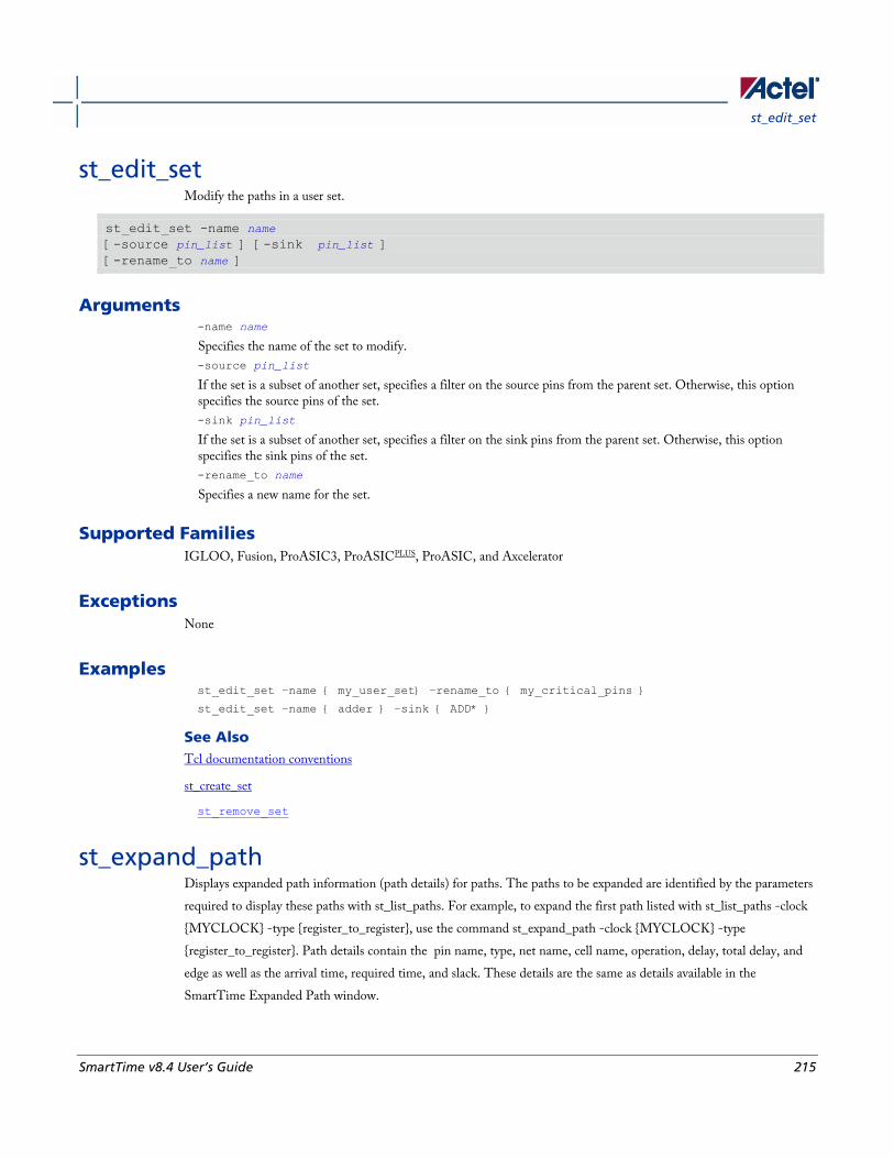
st_edit_set
SmartTime v8.4 User’s Guide 215
st_edit_set Modify the paths in a user set.
st_edit_set -name name [-source pin_list ] [-sink pin_list ] [-rename_to name ]
Arguments -name name
Specifies the name of the set to modify.
-source pin_list
If the set is a subset of another set, specifies a filter on the source pins from the parent set. Otherwise, this option specifies the source pins of the set.
-sink pin_list
If the set is a subset of another set, specifies a filter on the sink pins from the parent set. Otherwise, this option specifies the sink pins of the set.
-rename_to name
Specifies a new name for the set.
Supported Families IGLOO, Fusion, ProASIC3, ProASICPLUS, ProASIC, and Axcelerator
Exceptions None
Examples st_edit_set –name { my_user_set} –rename_to { my_critical_pins }
st_edit_set –name { adder } –sink { ADD* }
See Also Tcl documentation conventions
st_create_set
st_remove_set
st_expand_path Displays expanded path information (path details) for paths. The paths to be expanded are identified by the parameters
required to display these paths with st_list_paths. For example, to expand the first path listed with st_list_paths -clock
{MYCLOCK} -type {register_to_register}, use the command st_expand_path -clock {MYCLOCK} -type
{register_to_register}. Path details contain the pin name, type, net name, cell name, operation, delay, total delay, and
edge as well as the arrival time, required time, and slack. These details are the same as details available in the
SmartTime Expanded Path window.

Data Change History
216 SmartTime v8.4 User’s Guide
st_expand_path [-set name] [-clock clock_id -type value] [-in_to_out] [-source_clock clock_id -sink_clock clock_id] [-source pin_list] [-sink pin_list] [-analysis value] [-index list_of_indices] [-format value]
Arguments -set name
Displays a list of paths from the named set. You can either use the -set option to specify a set name, or use both -clock and -type to specify a set. A list of valid set names includes "in_to_out", as well as any user set names.
-clock clock_id
Displays the set of paths belonging to the specified clock domain. You can either use this option along with -type to specify a set or use the -set option to specify the name of the set to display.
-in_to_out
Specifies that the paths should be from the set "Input to Output, which includes paths that start at input ports and end at output ports.
-type value
Specifies the type of paths in the clock domain to display in a list. You can only use this option with the -clock option, not by itself. You can either use this option along with -clock to specify a set or use the -set option to specify a set name.
Value Description
reg_to_reg Paths between registers in the design
async_to_reg Paths from asynchronous pins to registers
reg_to_asyn Paths from registers to asynchronous pins
external_recovery The set of paths from inputs to asynchronous pins
external_removal The set of paths from inputs to asynchronous pins
external_setup Paths from input ports to registers
Paths from input ports to registers
clock_to_out Paths from registers to output ports
-source_clock clock_id
Displays a list of timing paths for an inter-clock domain set belonging to the source clock specified. You can only use this option with the -sink_clock option, not by itself.
-sink_clock clock_id

st_expand_path
SmartTime v8.4 User’s Guide 217
Displays a list of timing paths for an inter-clock domain set belonging to the sink clock specified. You can only use this option with the -source_clock option, not by itself.
-source pin_list
Specifies a filter on the source pins of the paths to be listed.
-sink pin_list
Specifies a filter on the sink pins of the paths to be listed.
-analysis name
Specifies the analysis type for the paths to be listed. The following table shows the acceptable values for this argument:
Value Description
maxdelay Maximum delay analysis
mindelay Minimum delay analysis
-index list_of_indices
Specifies which paths to display. The index starts at 1 and defaults to 1. Only values lower than the max_paths option will be expanded.
-format value
Specifies the file format of the output. The following table shows the acceptable values for this argument:
Value Description
text ASCII text format
csv Comma separated value fie format
Supported Families IGLOO, Fusion, ProASIC3, ProASICPLUS, ProASIC, and Axcelerator
Exceptions None
Examples Note: The following example returns a list of five paths:
st_expand_path –clock { myclock } –type {reg_to_reg }
st_expand_path –clock {myclock} –type {reg_to_reg} –index { 1 2 3 } –format text
See Also Tcl documentation conventions
st_list_paths
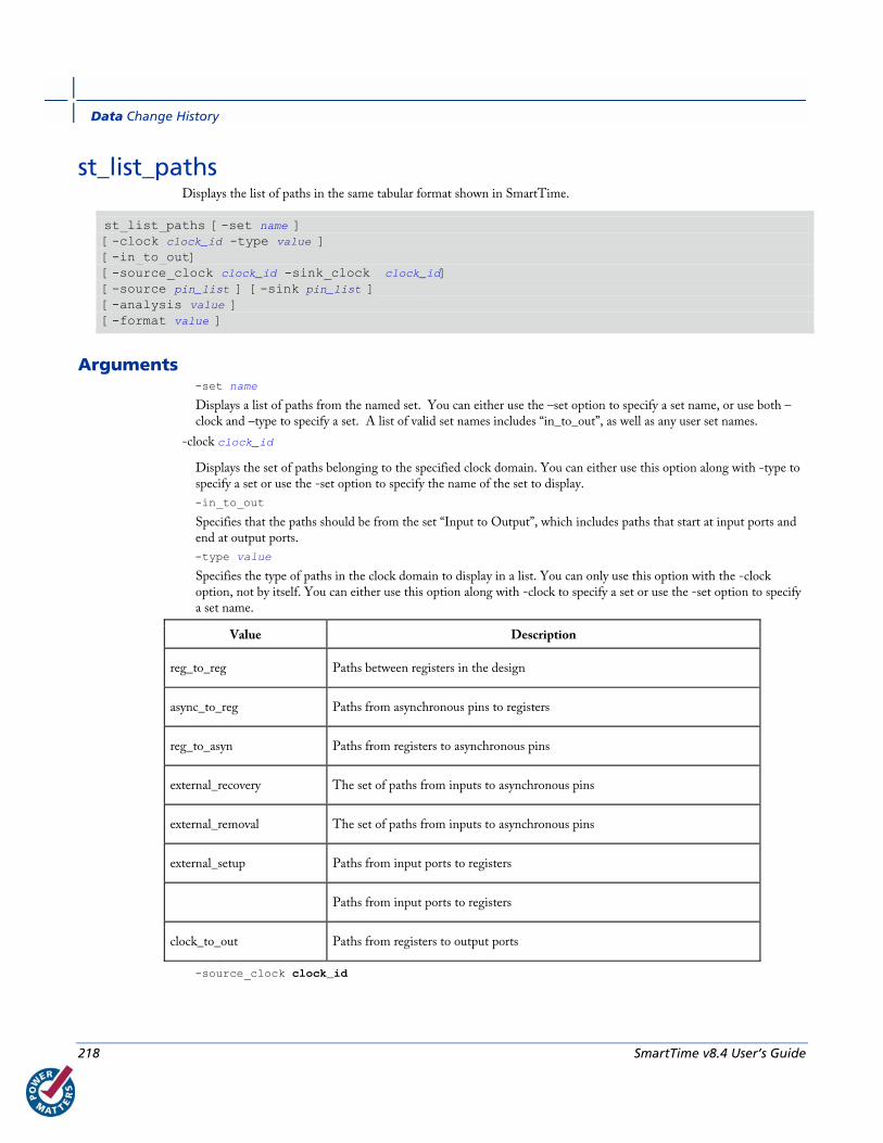
Data Change History
218 SmartTime v8.4 User’s Guide
st_list_paths Displays the list of paths in the same tabular format shown in SmartTime.
st_list_paths [-set name ] [-clock clock_id -type value ] [-in_to_out] [-source_clock clock_id -sink_clock clock_id] [-source pin_list ] [-sink pin_list ] [-analysis value ] [-format value ]
Arguments -set name
Displays a list of paths from the named set. You can either use the –set option to specify a set name, or use both –clock and –type to specify a set. A list of valid set names includes “in_to_out”, as well as any user set names.
-clock clock_id
Displays the set of paths belonging to the specified clock domain. You can either use this option along with -type to specify a set or use the -set option to specify the name of the set to display.
-in_to_out
Specifies that the paths should be from the set “Input to Output”, which includes paths that start at input ports and end at output ports.
-type value
Specifies the type of paths in the clock domain to display in a list. You can only use this option with the -clock option, not by itself. You can either use this option along with -clock to specify a set or use the -set option to specify a set name.
Value Description
reg_to_reg Paths between registers in the design
async_to_reg Paths from asynchronous pins to registers
reg_to_asyn Paths from registers to asynchronous pins
external_recovery The set of paths from inputs to asynchronous pins
external_removal The set of paths from inputs to asynchronous pins
external_setup Paths from input ports to registers
Paths from input ports to registers
clock_to_out Paths from registers to output ports
-source_clock clock_id
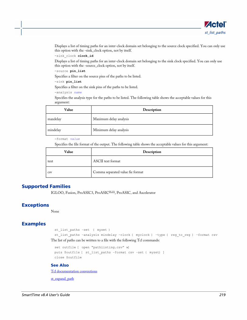
st_list_paths
SmartTime v8.4 User’s Guide 219
Displays a list of timing paths for an inter-clock domain set belonging to the source clock specified. You can only use this option with the -sink_clock option, not by itself.
-sink_clock clock_id
Displays a list of timing paths for an inter-clock domain set belonging to the sink clock specified. You can only use this option with the -source_clock option, not by itself.
-source pin_list
Specifies a filter on the source pins of the paths to be listed.
-sink pin_list
Specifies a filter on the sink pins of the paths to be listed.
-analysis name
Specifies the analysis type for the paths to be listed. The following table shows the acceptable values for this argument:
Value Description
maxdelay Maximum delay analysis
mindelay Minimum delay analysis
-format value
Specifies the file format of the output. The following table shows the acceptable values for this argument:
Value Description
text ASCII text format
csv Comma separated value fie format
Supported Families IGLOO, Fusion, ProASIC3, ProASICPLUS, ProASIC, and Axcelerator
Exceptions None
Examples st_list_paths –set { myset }
st_list_paths –analysis mindelay –clock { myclock } –type { reg_to_reg } –format csv
The list of paths can be written to a file with the following Tcl commands:
set outfile [ open “pathlisting.csv” w]
puts $outfile [ st_list_paths –format csv –set { myset} ]
close $outfile
See Also Tcl documentation conventions
st_expand_path
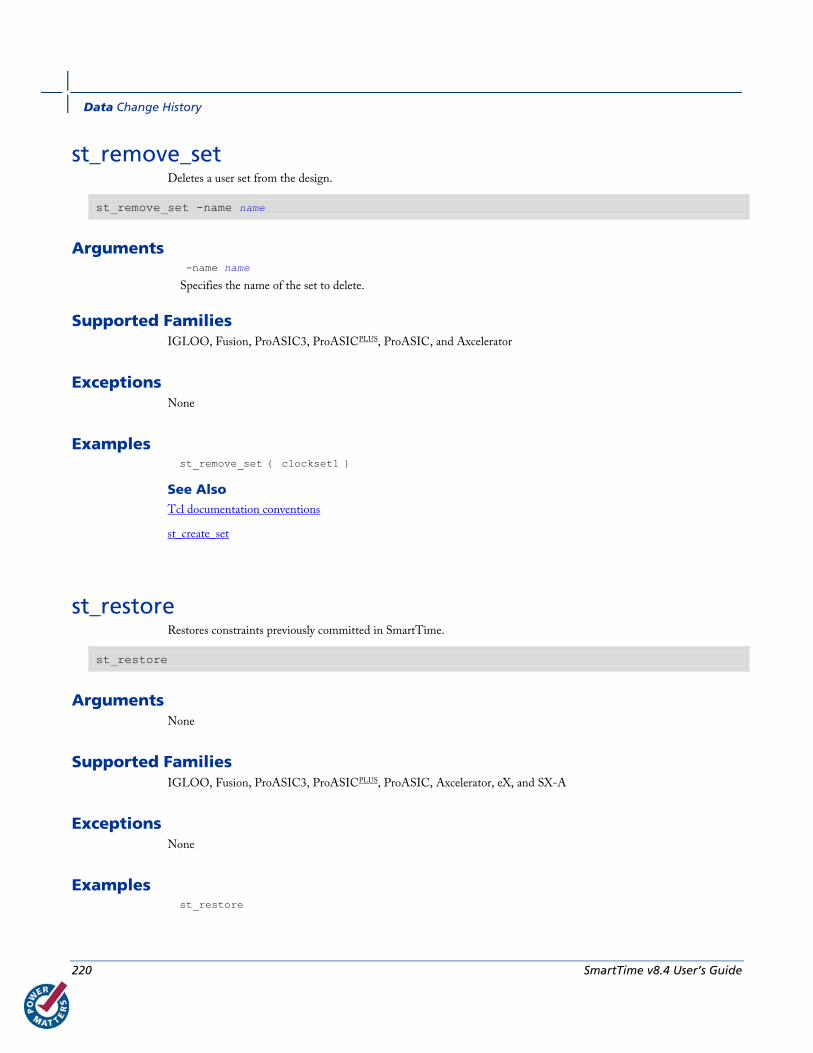
Data Change History
220 SmartTime v8.4 User’s Guide
st_remove_set Deletes a user set from the design.
st_remove_set -name name
Arguments -name name
Specifies the name of the set to delete.
Supported Families IGLOO, Fusion, ProASIC3, ProASICPLUS, ProASIC, and Axcelerator
Exceptions None
Examples st_remove_set { clockset1 }
See Also Tcl documentation conventions
st_create_set
st_restore Restores constraints previously committed in SmartTime.
st_restore
Arguments None
Supported Families IGLOO, Fusion, ProASIC3, ProASICPLUS, ProASIC, Axcelerator, eX, and SX-A
Exceptions None
Examples st_restore
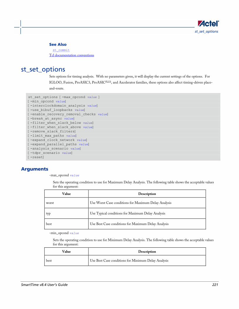
st_set_options
SmartTime v8.4 User’s Guide 221
See Also st_commit
Tcl documentation conventions
st_set_options Sets options for timing analysis. With no parameters given, it will display the current settings of the options. For
IGLOO, Fusion, ProASIC3, ProASICPLUS, and Axcelerator families, these options also affect timing-driven place-
and-route.
st_set_options [-max_opcond value ] [-min_opcond value] [-interclockdomain_analysis value] [-use_bibuf_loopbacks value] [-enable_recovery_removal_checks value] [-break_at_async value] [-filter_when_slack_below value] [-filter_when_slack_above value] [-remove_slack_filters] [-limit_max_paths value] [-expand_clock_network value] [-expand_parallel_paths value] [-analysis_scenario value] [-tdpr_scenario value] [-reset]
Arguments -max_opcond value
Sets the operating condition to use for Maximum Delay Analysis. The following table shows the acceptable values for this argument:
Value Description
worst Use Worst Case conditions for Maximum Delay Analysis
typ Use Typical conditions for Maximum Delay Analysis
best Use Best Case conditions for Maximum Delay Analysis
-min_opcond value
Sets the operating condition to use for Minimum Delay Analysis. The following table shows the acceptable values for this argument:
Value Description
best Use Best Case conditions for Minimum Delay Analysis
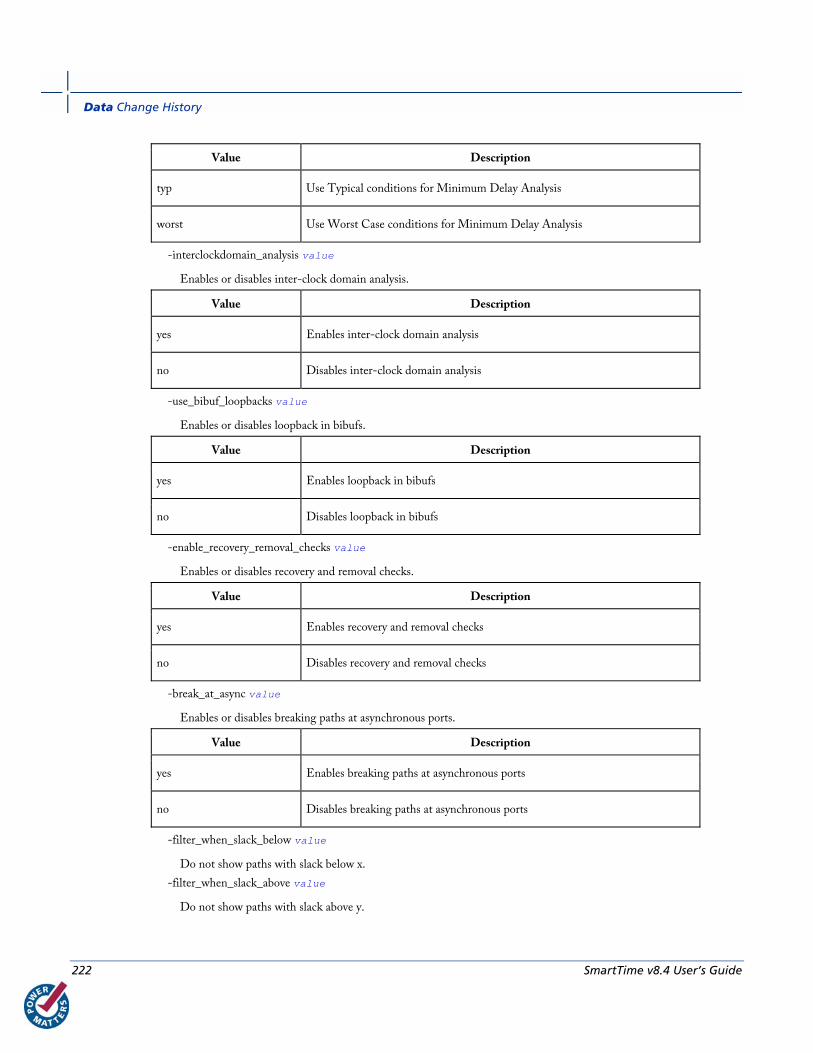
Data Change History
222 SmartTime v8.4 User’s Guide
Value Description
typ Use Typical conditions for Minimum Delay Analysis
worst Use Worst Case conditions for Minimum Delay Analysis
-interclockdomain_analysis value
Enables or disables inter-clock domain analysis.
Value Description
yes Enables inter-clock domain analysis
no Disables inter-clock domain analysis
-use_bibuf_loopbacks value
Enables or disables loopback in bibufs.
Value Description
yes Enables loopback in bibufs
no Disables loopback in bibufs
-enable_recovery_removal_checks value
Enables or disables recovery and removal checks.
Value Description
yes Enables recovery and removal checks
no Disables recovery and removal checks
-break_at_async value
Enables or disables breaking paths at asynchronous ports.
Value Description
yes Enables breaking paths at asynchronous ports
no Disables breaking paths at asynchronous ports
-filter_when_slack_below value
Do not show paths with slack below x.
-filter_when_slack_above value
Do not show paths with slack above y.

st_set_options
SmartTime v8.4 User’s Guide 223
-remove_slack_filters
Remove all existing slack filters.
-limit_max_paths value
Limit path reporting commands to a maximum of <n> paths, where n is a value of 0 or higher.
-expand_clock_network value
Enables or disables expanded clock network information in expanded paths.
Value Description
yes Enables expanded clock network information in paths
no Disables expanded clock network information in paths
-expand_parallel_paths value
Expand a maximum of <n> parallel paths, where n is a value of 0 or higher. If n is 0 or 1, only one path will be expanded when viewing expanded paths.
-analysis_scenario value
Set the timing constraints scenario to be used for both maximum delay and minimum delay analysis. The argument must be a valid scenario name.
Note: This option does not affect the timing scenario used for TDPR.
-tdpr_scenario value
Set the timing constraints scenario to be used by the place and route engine. The argument must be a valid scenario name.
Note: This option does not affect the timing scenario used for analysis.
-reset
Reset all options to their default values, except for scenarios used for analysis and TDPR that remain unchanged.
Supported Families IGLOO, Fusion, ProASIC3, ProASICPLUS, ProASIC, Axcelerator, eX, and SX-A
Exceptions None
Examples st_set_options –max_opcond worst \
-min_opcond best \
-interclockdomain_analysis true \
-enable_removal_recovery_checks true
st_set_options –limit_max_paths 50 –remove_slack_filters \
–filter_when_slack_above 3
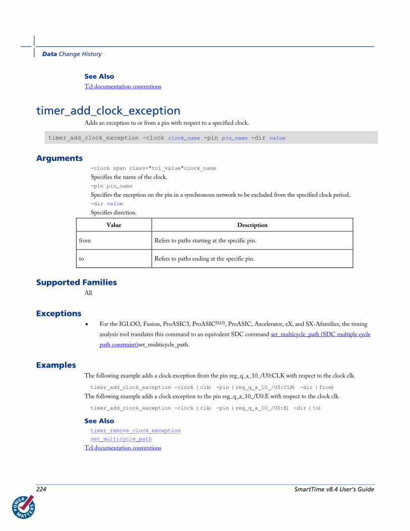
Data Change History
224 SmartTime v8.4 User’s Guide
See Also Tcl documentation conventions
timer_add_clock_exception Adds an exception to or from a pin with respect to a specified clock.
timer_add_clock_exception -clock clock_name -pin pin_name -dir value
Arguments -clock span class="tcl_value"clock_name
Specifies the name of the clock.
-pin pin_name
Specifies the exception on the pin in a synchronous network to be excluded from the specified clock period.
-dir value
Specifies direction.
Value Description
from Refers to paths starting at the specific pin.
to Refers to paths ending at the specific pin.
Supported Families All
Exceptions • For the IGLOO, Fusion, ProASIC3, ProASICPLUS, ProASIC, Axcelerator, eX, and SX-Afamilies, the timing
analysis tool translates this command to an equivalent SDC command set_multicycle_path (SDC multiple cycle
path constraint)set_muliticycle_path.
Examples The following example adds a clock exception from the pin reg_q_a_10_/U0:CLK with respect to the clock clk.
timer_add_clock_exception -clock {clk} -pin {reg_q_a_10_/U0:CLK} -dir {from}
The following example adds a clock exception to the pin reg_q_a_10_/U0:E with respect to the clock clk.
timer_add_clock_exception -clock {clk} -pin {reg_q_a_10_/U0:E} -dir {to}
See Also timer_remove_clock_exception
set_multicycle_path
Tcl documentation conventions

timer_add_pass
SmartTime v8.4 User’s Guide 225
timer_add_pass Adds a pin to the list of pins that the path must be shown passing through in the timing analysis tool.
timer_add_pass -pin pin_name
Arguments -pin pin_name
Specifies the name of the pin to be included for displaying the timing path through it.
Supported Families All
Description When you set a pass on a module pin, you can see a path through individual pins.
Exceptions • For the IGLOO, Fusion, ProASIC3, ProASICPLUS, ProASIC, Axcelerator, eX, and SX-A families, the timing
analysis tool ignores the timer_add_pass command.
Examples This example adds a pass through the pin "reg_q_a_0_:CLK":
>timer_add_pass -pin {reg_q_a_0_:CLK}
This example adds a pass through a clear pin "reg_q_a_0_:CLR":
timer_add_pass -pin {reg_q_a_0_:CLR}
See Also timer_add_stop
Tcl documentation conventions
timer_add_stop Adds the specified pin to the list of pins through which the paths will not be displayed in the timing analysis tool.
timer_add_stop -pin pin_name
Arguments -pin pin_name
Specifies the name of the pin through which the path will not be displayed.
Supported Families All

Data Change History
226 SmartTime v8.4 User’s Guide
Description Without stop points, you see all paths from pad to pad in the design. If you do not want to see the paths going through
register clock pins, you can specify these as stop points. The path going through the specified pins will not be displayed.
Exceptions • For the IGLOO, Fusion, ProASIC3, ProASICPLUS, ProASIC, Axcelerator, eX, and SX-A families, Actel
recommends that you use the equivalent SDC command set_false_path.
Examples The following example adds a stop to the pin "a<2>":
timer_add_stop -pin {a<2>}
The following example adds a stop to a clock and the clear pin "reg_q_a_0_:CLR":
timer_add_stop -pin {reg_q_a_0_:CLK}
timer_add_stop -pin {reg_q_a_0_:CLR}
See Also timer_add_pass
set_false_path (SDC false path constraint)
Tcl documentation conventions
timer_commit Saves the changes made to constraints into the Designer database.
timer_commit
Arguments None
Supported Families All
Exceptions • For theIGLOO, Fusion, ProASIC3, ProASICPLUS, ProASIC, Axcelerator, eX, and SX-A families, Actel
recommends that you use import_source import_source. This automatically commits constraints to the design
database.
Examples timer_commit
See Also import_source
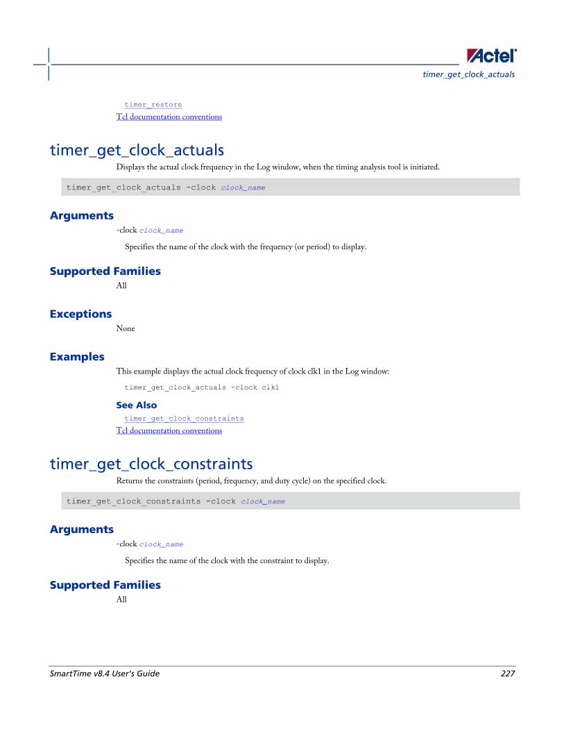
timer_get_clock_actuals
SmartTime v8.4 User’s Guide 227
timer_restore
Tcl documentation conventions
timer_get_clock_actuals Displays the actual clock frequency in the Log window, when the timing analysis tool is initiated.
timer_get_clock_actuals -clock clock_name
Arguments -clock clock_name
Specifies the name of the clock with the frequency (or period) to display.
Supported Families All
Exceptions None
Examples This example displays the actual clock frequency of clock clk1 in the Log window:
timer_get_clock_actuals -clock clk1
See Also timer_get_clock_constraints
Tcl documentation conventions
timer_get_clock_constraints Returns the constraints (period, frequency, and duty cycle) on the specified clock.
timer_get_clock_constraints -clock clock_name
Arguments -clock clock_name
Specifies the name of the clock with the constraint to display.
Supported Families All
Data Change History
228 SmartTime v8.4 User’s Guide
Exceptions None
Examples The following example displays the clock constraints on the clock clk in the Log window:
timer_get_clock_constraints -clock clk
See Also timer_get_clock_actuals
Tcl documentation conventions
timer_get_maxdelay Displays the maximum delay constraint between two pins in a path in the Log window.
timer_get_maxdelay -from source_pin -to destination_pin
Arguments -from source_pin
Specifies the name of the source pin in the path.
-to destination_pin
Specifies the name of the destination pin in the path.
Supported Families All
Exceptions None
Examples The following example displays the maximum delay constraint from the pin clk166 to the pin reg_q_a_9_/U0:CLK in
the Log window:
timer_get_maxdelay -from {clk166} -to {reg_q_a_9_/U0:CLK}
See Also timer_set_maxdelay
Tcl documentation conventions

timer_get_path
SmartTime v8.4 User’s Guide 229
timer_get_path Displays the path between the specified pins in the Log window.
timer_get_path -from source_pin -to destination_pin [-exp value]\ [-sort value]\ [-order value]\ [-case value]\ [-maxpath maximum_paths]\ [-maxexpath maximum_paths_to_expand]\ [-mindelay minimum_delay]\ [-maxdelay maximum_delay]\ [-breakatclk value]\ [-breakatclr value]
Arguments -from source_pin
Specifies the name of the source pin for the path.
-to destination_pin
Specifies the name of the destination pin for the path.
-exp value
Specifies whether to expand the path. The following table shows the acceptable values for this argument:
Value Description
yes Expands the path
no Does not expand the path
-sort value
Specifies whether to sort the path by either the actual delay or slack value. The following table shows the acceptable values for this argument:
Value Description
actual Sorts the path by the actual delay value
slack Sorts the path by the slack value
-order value
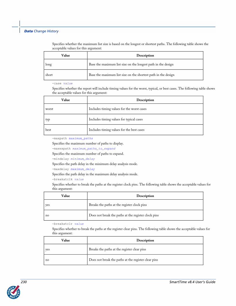
Data Change History
230 SmartTime v8.4 User’s Guide
Specifies whether the maximum list size is based on the longest or shortest paths. The following table shows the acceptable values for this argument:
Value Description
long Base the maximum list size on the longest path in the design
short Base the maximum list size on the shortest path in the design
-case value
Specifies whether the report will include timing values for the worst, typical, or best cases. The following table shows the acceptable values for this argument:
Value Description
worst Includes timing values for the worst cases
typ Includes timing values for typical cases
best Includes timing values for the best cases
-maxpath maximum_paths
Specifies the maximum number of paths to display.
-maxexpath maximum_paths_to_expand
Specifies the maximum number of paths to expand.
-mindelay minimum_delay
Specifies the path delay in the minimum delay analysis mode.
-maxdelay maximum_delay
Specifies the path delay in the maximum delay analysis mode.
-breakatclk value
Specifies whether to break the paths at the register clock pins. The following table shows the acceptable values for this argument:
Value Description
yes Breaks the paths at the register clock pins
no Does not break the paths at the register clock pins
-breakatclr value
Specifies whether to break the paths at the register clear pins. The following table shows the acceptable values for this argument:
Value Description
yes Breaks the paths at the register clear pins
no Does not break the paths at the register clear pins
timer_get_path_constraints
SmartTime v8.4 User’s Guide 231
Supported Families All
Exceptions None
Examples The following example returns the paths from input port headdr_dat<31> to the input pin of register
u0_headdr_data1_reg/data_out_t_31 under typical conditions.
timer_get_path -from "headdr_dat<31>" \
-to "u0_headdr_data1_reg/data_out_t_31/U0:D" \
-case typ \
-exp "yes" \
-maxpath "100" \
-maxexpapth "10"
The following example returns the paths from the clock pin of register gearbox_inst/bits64_out_reg<55> to the output
port pma_tx_data_64bit[55]
timer_get_path -from "gearbox_inst/bits64_out_reg<55>/U0:CLK" \
-to {pma_tx_data_64bit[55]} \
-exp "yes"
See Also Tcl documentation conventions
timer_get_path_constraints Displays the path constraints that were set as the maximum delay constraint in the timing analysis tool.
timer_get_path_constraints
Arguments None
Supported Families All
Description This command lists the paths constrained by maximum delay values. The information is displayed in the Log window.
If no maximum delay constraints are set, this command does not report anything.
Data Change History
232 SmartTime v8.4 User’s Guide
Exceptions None
Examples Invoking timer_get_path_constraints displays the following paths and their delay constraints in the Log window:
max_delay -from [all_inputs] -to [all_outputs] = 12 ns
max_delay -from p_f_testwdata0 p_f_testwdata1 -to p_f_dacuwdata0 p_f_dacuwdata1 r_f_dacuwdata0 r_f_dacuwdata1 = 8 ns
See Also timer_set_maxdelay
Tcl documentation conventions
timer_remove_all_constraints Removes all timing constraints in the current design.
timer_remove_all_constraints
Arguments None
Supported Families All
Exceptions None
Examples The following example removes all of the constraints from the design and then commits the changes:
timer_remove_all_constraints
timer_commit
See Also timer_commit
Tcl documentation conventions

timer_remove_clock_exception
SmartTime v8.4 User’s Guide 233
timer_remove_clock_exception Removes the previously set clock constraint.
timer_remove_clock_exception -clock clock_name -pin pin_name -dir value
Arguments -clock clock_name
Specifies the name of the clock from which to remove the constraint.
-pin pin_name
Specifies the name of the pin to remove.
-dir value
Specifies direction.
Value Description
from Refers to paths starting at the specified pin.
to Refers to paths ending at the specified pin.
Supported Families All
Exceptions • For the IGLOO, Fusion, ProASIC3, ProASICPLUS, ProASIC, Axcelerator, eX, and SX-A families, the timing
analysis tool ignores the timer_remove_clock_exceptions command. To remove the clock exception, use the Set
Multicycle Constraint dialog box.
Examples This example removes a clock exception from the pin reg_q_a_10_/U0:CLK with respect to the clock clk:
timer_remove_clock_exception -clock {clk} -pin {reg_q_a_10_/U0:CLK} -dir {from}
This example removes a clock exception to the pin reg_q_a_10_/U0:E with respect to the clock clk:
timer_remove_clock_exception -clock {clk} -pin {reg_q_a_10_/U0:E} -dir {to}.
See Also timer_add_clock_exception
Tcl documentation conventions
Set Multicycle Constraint dialog box
Data Change History
234 SmartTime v8.4 User’s Guide
timer_remove_pass Removes the previously entered path pass constraint.
timer_remove_pass -pin pin_name
Arguments -pin pin_name
Specifies the name of the pin from which to remove the path pass constraint.
Supported Families All
Exceptions • For the IGLOO, Fusion, ProASIC3, ProASICPLUS, ProASIC, Axcelerator, eX, and SX-A families, the timing
analysis tool ignores the timer_remove_pass command.
Examples The following example removes the pass constraint from the clock pin reg_q_a_0_:CLK:
timer_remove_pass -pin {reg_q_a_0_:CLK}
See Also timer_add_pass
Tcl documentation conventions
timer_remove_stop Removes the previously entered path stop constraint on the specified pin.
timer_remove_stop -pin pin_name
Arguments -pin pin_name
Specifies the name of the pin from which to remove the path stop constraint.
Supported Families All
Description If you remove a path stop constraint using the Timer GUI, and then export a script using File > Export > Script files,
the resulting script will contain timer_remove_pass -pin pin_name instead of timer_remove_stop -
pin pin_name.
timer_restore
SmartTime v8.4 User’s Guide 235
Exceptions • For the IGLOO, Fusion, ProASIC3, ProASICPLUS, ProASIC, Axcelerator, eX, and SX-A families, Actel
recommends the following flow:
1. Open SmartTime > Set False Path Constraint dialog box.
2. Look for the pin name in the Through: list (Note: You must not have any entry
selected in the From or To lists).
3. Delete this pin.
Examples The following example removes the path stop constraint on the clear pin reg_q_a_0_:CLR:
timer_remove_stop -pin {reg_q_a_0_:CLR}
See Also timer_add_stop
Tcl documentation conventions
Set False Path Constraint dialog box
timer_restore Restores constraints previously committed in Timer.
timer_restore
Arguments None
Supported Families All
Exceptions None
Examples timer_restore
See Also timer_commit
Tcl documentation conventions

Data Change History
236 SmartTime v8.4 User’s Guide
timer_set_maxdelay Adds a maximum delay constraint to the specified path.
timer_set_maxdelay -from source_pin \ -to destination_pin \ [-unit {value}] -delay delay_value
Arguments -from source_pin
Specifies the name of the source pin in the path.
-to destination_pin
Specifies the name of the destination pin in the path.
-unit {value}
Specifies whether the delay unit is in nanoseconds or picoseconds. The following table shows the acceptable values for this argument:
Value Description
ns Sets the delay in nanoseconds
ps Sets the delay in picoseconds
-delay delay_value
Specifies the actual delay value for the path.
Supported Families All
Exceptions • For the IGLOO, Fusion, ProASIC3, ProASICPLUS, ProASIC, Axcelerator, SX-S, SX-A, and eX families, Actel
recommends that you use the equivalent SDC command set_max_delayset_max_delay.
Examples The following example sets a maximum delay of 20 nanoseconds from register reg1 to output pin out1:
timer_set_maxdelay -from {reg1:CLK} -to {out1} -unit {ns} -delay 20.00
See Also timer_get_maxdelay
set_max_delay (SDC max path constraint)
Tcl documentation conventions
timer_setenv_clock_freq
SmartTime v8.4 User’s Guide 237
timer_setenv_clock_freq Sets a required clock frequency for the specified clock in megahertz (MHz).
timer_setenv_clock_freq -clock clock_name -freq value [-dutycycle dutycycle]
Arguments -clock clock_name
Specifies the name of the clock for which to set the required frequency.
-freq value
Specifies the frequency in MHz.
-dutycycle dutycycle
Specifies the duty cycle for the clock constraint.
Supported Families All
Exceptions • For the IGLOO, Fusion, ProASIC3, ProASICPLUS, ProASIC, Axcelerator, SX-S, SX-A, and eX families, Actel
recommends that you use the equivalent SDC command create_clockcreate_clock.
Examples The following example sets a clock frequency of 100MHz on the clock clk1:
timer_setenv_clock_freq -clock {clk1} -freq 100.00
See Also create_clock (SDC clock constraint)
Tcl documentation conventions
timer_setenv_clock_period
timer_setenv_clock_period Sets the clock period constraint on the specified clock.
timer_setenv_clock_period -clock clock_name \ [-unit {value}] -period period_value\ [-dutycycle dutycycle]
Arguments -clock clock_name
Specifies the name of the clock for which to set the period.
-unit {value}
Data Change History
238 SmartTime v8.4 User’s Guide
Specifies the unit for the clock period constraint. The default is ns. The following table shows the acceptable values for this argument:
Value Description
ns nanoseconds
ps picoseconds
-period period_value
Specifies the period in the specified unit.
-dutycycle dutycycle
Specifies the duty cycle for the clock constraint.
Supported Families All
Exceptions • For the IGLOO, Fusion, ProASIC3, ProASICPLUS, ProASIC, Axcelerator, SX-S, SX-A, and eX families, Actel
recommends that you use the equivalent SDC command create_clockcreate_clock.
Examples The following example sets a clock period of 2.40ns on the clock clk1:
timer_setenv_clock_period -clock clk1 -unit {ns} -period 2.40
See Also timer_setenv_clock_freq
Tcl documentation conventions
report (Timing) using SmartTime Creates a timing report.
report -type timing filename\ [−print_summary value]\ [−analysis value]\ [−use_slack_threshold value]\ [−slack_threshold value]\ [−print_paths value]\ [−max_paths value]\ [−max_expanded_paths value]\ [−include_user_sets value]\ [−include_pin_to_pin value]\ [−select_clock_domains value]\ [−clock_domain clock_domain_list] [−format value]
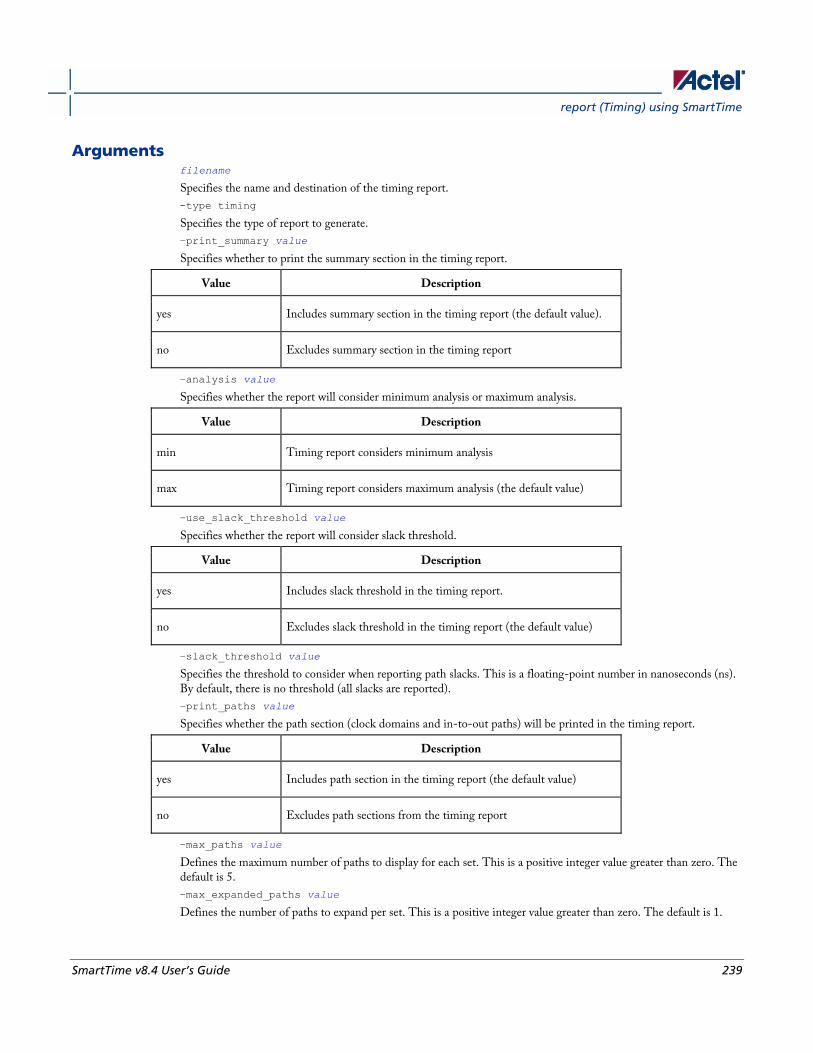
report (Timing) using SmartTime
SmartTime v8.4 User’s Guide 239
Arguments filename
Specifies the name and destination of the timing report.
-type timing
Specifies the type of report to generate.
−print_summary value
Specifies whether to print the summary section in the timing report.
Value Description
yes Includes summary section in the timing report (the default value).
no Excludes summary section in the timing report
−analysis value
Specifies whether the report will consider minimum analysis or maximum analysis.
Value Description
min Timing report considers minimum analysis
max Timing report considers maximum analysis (the default value)
−use_slack_threshold value
Specifies whether the report will consider slack threshold.
Value Description
yes Includes slack threshold in the timing report.
no Excludes slack threshold in the timing report (the default value)
−slack_threshold value
Specifies the threshold to consider when reporting path slacks. This is a floating-point number in nanoseconds (ns). By default, there is no threshold (all slacks are reported).
−print_paths value
Specifies whether the path section (clock domains and in-to-out paths) will be printed in the timing report.
Value Description
yes Includes path section in the timing report (the default value)
no Excludes path sections from the timing report
−max_paths value
Defines the maximum number of paths to display for each set. This is a positive integer value greater than zero. The default is 5.
−max_expanded_paths value
Defines the number of paths to expand per set. This is a positive integer value greater than zero. The default is 1.
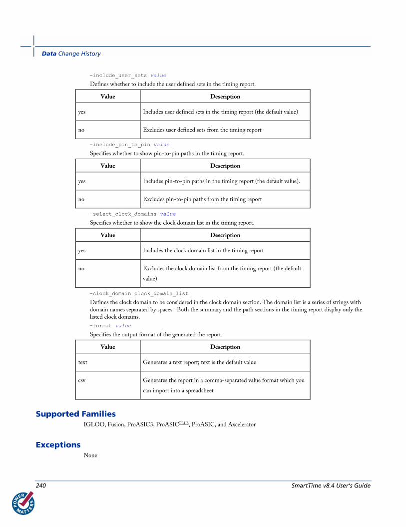
Data Change History
240 SmartTime v8.4 User’s Guide
−include_user_sets value
Defines whether to include the user defined sets in the timing report.
Value Description
yes Includes user defined sets in the timing report (the default value)
no Excludes user defined sets from the timing report
−include_pin_to_pin value
Specifies whether to show pin-to-pin paths in the timing report.
Value Description
yes Includes pin-to-pin paths in the timing report (the default value).
no Excludes pin-to-pin paths from the timing report
−select_clock_domains value
Specifies whether to show the clock domain list in the timing report.
Value Description
yes Includes the clock domain list in the timing report
no Excludes the clock domain list from the timing report (the default
value)
−clock_domain clock_domain_list
Defines the clock domain to be considered in the clock domain section. The domain list is a series of strings with domain names separated by spaces. Both the summary and the path sections in the timing report display only the listed clock domains.
−format value
Specifies the output format of the generated the report.
Value Description
text Generates a text report; text is the default value
csv Generates the report in a comma-separated value format which you
can import into a spreadsheet
Supported Families IGLOO, Fusion, ProASIC3, ProASICPLUS, ProASIC, and Axcelerator
Exceptions None

report (Timing violations) using SmartTime
SmartTime v8.4 User’s Guide 241
Examples The following example generates a timing report named timing_report.txt. The report does not print the summary
section. It includes a max-delay analysis and only reports paths with a slack value less than 0.50 ns. It reports a
maximum of 3 paths per section and does not report any expanded paths. It only reports timing information for the
clock domains count8_clock and count2_clk.
report -type timing -print_summary no \
-analysis max \
-use_slack_threshold yes \
-slack_threshold 0.50 \
-print_paths yes -max_paths 3 \
-max_expanded_paths 0 \
-include_user_sets yes \
-include_pin_to_pin yes \
-select_clock_domains yes \
-clock_domain {count8_clock count2_clk} \
timing_report.txt
See Also Tcl documentation conventions
report (Timing violations) using SmartTime
report (Datasheet) using SmartTime
report (Timing violations) using SmartTime Creates a timing violations report.
report -type timing_violations filename \ [−analysis value]\ [−use_slack_threshold value]\ [−slack_threshold value]\ [–limit_max_paths value]\ [−max_paths value]\ [−max_expanded_paths value] \ [−format value]
Arguments filename
Specifies the name and destination of the timing violations report.
-type timing_violations
Specifies the type of report to generate.
−analysis value

Data Change History
242 SmartTime v8.4 User’s Guide
Specifies whether to consider minimum analysis or maximum analysis in the timing violations report.
Value Description
min Timing report considers minimum analysis
max Timing report considers maximum analysis (the default value)
−use_slack_threshold value
Specifies whether to consider the slack threshold in the timing violations report.
Value Description
yes Includes slack threshold in the timing violations report
no Excludes slack threshold in the timing violations report (the default
value)
−slack_threshold value
Specifies the threshold to consider when reporting path slacks. This value is a floating-point number in nanoseconds (ns). By default, there is no threshold (all slacks reported).
–limit_max_paths value
Specifies if the paths are limited by the number of paths.
Value Description
yes Limits the maximum number of paths to report
no Specifies that there is no limit to the number of paths to report (the
default value)
−max_paths value
Specifies the maximum number of paths to display for each set. This value is a positive integer value greater than zero. Default is 100.
−max_expanded_paths value
Specifies the number of paths to expand per set. This value is a positive integer value greater than zero. The default is 0.
−format value
Specifies the output format of the generated report.
Value Description
text Generates a text report; text is the default value
csv Generates the report in a comma-separated value format which you
can import into a spreadsheet

report (Datasheet) using SmartTime
SmartTime v8.4 User’s Guide 243
Supported Families IGLOO, Fusion, ProASIC3, ProASICPLUS, ProASIC, and Axcelerator
Exceptions None
Examples The following example generates a timing violations report named timg_viol.txt. The report considers an analysis
using maximum delays and does not filter paths based on slack threshold. It reports 2 paths per section and 1 expanded
path per section.
report -type timing_violations \
-analysis max -use_slack_threshold no \
-limit_max_paths -yes \
-max_paths 2 \
-max_expanded_paths 1 \
timg_viol.txt
See Also Tcl documentation conventions
report (Timing) using SmartTime
report (Datasheet) using SmartTime
report (Datasheet) using SmartTime Creates a datasheet report.
report -type datasheet filename \ [−format value]
Arguments filename
Specifies the name and destination of the datasheet report.
−format value
Specifies the output format of the generated the report.
Value Description
text Generates a text report; text is the default value
csv Generates the report in a comma-separated value format which you can import
into a spreadsheet

Data Change History
244 SmartTime v8.4 User’s Guide
Supported Families IGLOO, Fusion, ProASIC3, ProASICPLUS, ProASIC, Axcelerator, eX, and SX-A
Exceptions None
Examples The following example generates a datasheet report named datasheet.txt.
report -type datasheet -format Text datasheet.txt
See Also Tcl documentation conventions
report (Timing) using SmartTime
report (Timing violations) using SmartTime
report (Bottleneck) using SmartTime Creates a bottleneck report.
report -type bottleneck [-cost_type {value} ] [-use_slack_threshold{value} ] [-slack_threshold {value} ] [-set_name {value} ] [-clock clock_id -set_type value ] [-source_clock clock_id -sink_clock clock_id] [-source {pin_list} ] [-sink {pin_list} ] [-max_instances {value} ] [-max_paths {value} ] [-max_parallel_paths {value} ] [-analysis_type {value} ] {filename} \ [−format value]
Arguments -cost_type value
Specifies the type of bottleneck cost. The default option is path_count.
Value Description
path_count Instances with the greatest number of path violations will have the highest
bottleneck cost
path_cost Instances with the largest combined timing violations will have the highest
bottleneck cost
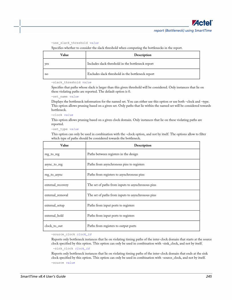
report (Bottleneck) using SmartTime
SmartTime v8.4 User’s Guide 245
-use_slack_threshold value
Specifies whether to consider the slack threshold when computing the bottlenecks in the report.
Value Description
yes Includes slack threshold in the bottleneck report
no Excludes slack threshold in the bottleneck report
-slack_threshold value
Specifies that paths whose slack is larger than this given threshold will be considered. Only instances that lie on these violating paths are reported. The default option is 0.
-set_name value
Displays the bottleneck information for the named set. You can either use this option or use both –clock and –type. This option allows pruning based on a given set. Only paths that lie within the named set will be considered towards bottleneck.
-clock value
This option allows pruning based on a given clock domain. Only instances that lie on these violating paths are reported.
-set_type value
This option can only be used in combination with the –clock option, and not by itself. The options allow to filter which type of paths should be considered towards the bottleneck.
Value Description
reg_to_reg Paths between registers in the design
async_to_reg Paths from asynchronous pins to registers
reg_to_async Paths from registers to asynchronous pins
external_recovery The set of paths from inputs to asynchronous pins
external_removal The set of paths from inputs to asynchronous pins
external_setup Paths from input ports to registers
external_hold Paths from input ports to registers
clock_to_out Paths from registers to output ports
-source_clock clock_id
Reports only bottleneck instances that lie on violating timing paths of the inter-clock domain that starts at the source clock specified by this option. This option can only be used in combination with -sink_clock, and not by itself.
-sink_clock clock_id
Reports only bottleneck instances that lie on violating timing paths of the inter-clock domain that ends at the sink clock specified by this option. This option can only be used in combination with -source_clock, and not by itself.
-source value
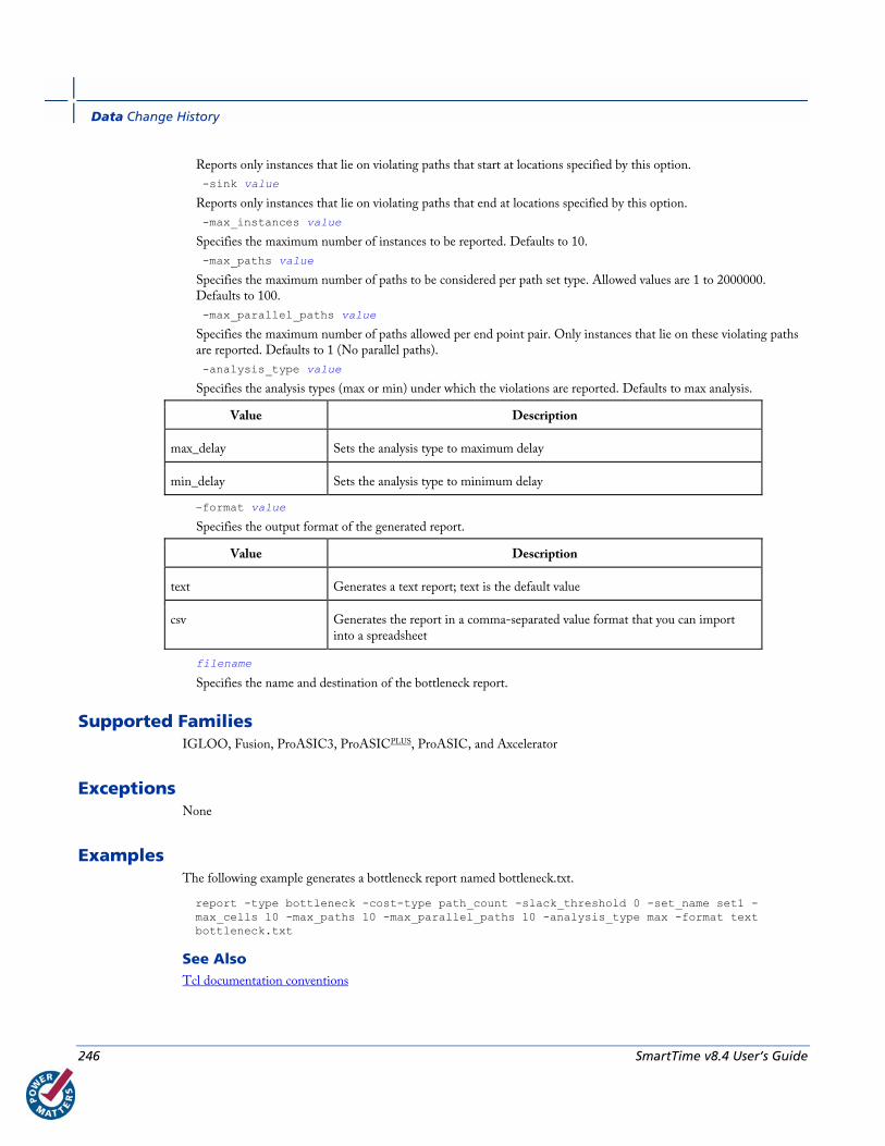
Data Change History
246 SmartTime v8.4 User’s Guide
Reports only instances that lie on violating paths that start at locations specified by this option.
-sink value
Reports only instances that lie on violating paths that end at locations specified by this option.
-max_instances value
Specifies the maximum number of instances to be reported. Defaults to 10.
-max_paths value
Specifies the maximum number of paths to be considered per path set type. Allowed values are 1 to 2000000. Defaults to 100.
-max_parallel_paths value
Specifies the maximum number of paths allowed per end point pair. Only instances that lie on these violating paths are reported. Defaults to 1 (No parallel paths).
-analysis_type value
Specifies the analysis types (max or min) under which the violations are reported. Defaults to max analysis.
Value Description
max_delay Sets the analysis type to maximum delay
min_delay Sets the analysis type to minimum delay
−format value
Specifies the output format of the generated report.
Value Description
text Generates a text report; text is the default value
csv Generates the report in a comma-separated value format that you can import into a spreadsheet
filename
Specifies the name and destination of the bottleneck report.
Supported Families IGLOO, Fusion, ProASIC3, ProASICPLUS, ProASIC, and Axcelerator
Exceptions None
Examples The following example generates a bottleneck report named bottleneck.txt.
report -type bottleneck -cost-type path_count -slack_threshold 0 -set_name set1 -max_cells 10 -max_paths 10 -max_parallel_paths 10 -analysis_type max -format text bottleneck.txt
See Also Tcl documentation conventions

SmartTime v8.4 User’s Guide 247
Constraints by File Format - SDC Command Reference
About Synopsys Design Constraints (SDC) Files Synopsys Design Constraints (SDC) is a Tcl-based format used by Synopsys tools to specify the design intent,
including the timing and area constraints for a design. Actel tools use a subset of the SDC format to capture supported
timing constraints. You can import or export an SDC file from the Designer software. Any timing constraint that you
can enter using Designer tools, can also be specified in an SDC file.
Use the SDC-based flow to share timing constraint information between Actel tools and third-party EDA tools.
Command Action
create_clock Creates a clock and defines its characteristics
create_generated_clock Creates an internally generated clock and defines its characteristics
set_clock_latency Defines the delay between an external clock source and the definition pin of a clock within
SmartTime
set_false_path Identifies paths that are to be considered false and excluded from the timing analysis
set_input_delay Defines the arrival time of an input relative to a clock
set_load Sets the load to a specified value on a specified port
set_max_delay Specifies the maximum delay for the timing paths
set_min_delay Specifies the minimum delay for the timing paths
set_multicycle_path Defines a path that takes multiple clock cycles
set_output_delay Defines the output delay of an output relative to a clock
See Also Constraint Entry
SDC Syntax Conventions
Importing Constraint Files

Constraints by File Format - SDC Command Reference
248 SmartTime v8.4 User’s Guide
SDC Syntax Conventions The following table shows the typographical conventions that are used for the SDC command syntax.
Syntax Notation
Description
command -
argument
Commands and arguments appear in Courier New typeface.
variable Variables appear in blue, italic Courier New typeface. You must substitute an
appropriate value for the variable.
[-argument
value]
Optional arguments begin and end with a square bracket.
Note: SDC commands and arguments are case sensitive.
Example The following example shows syntax for the create_clock command and a sample command:
create_clock -period period_value [-waveform edge_list] source
create_clock –period 7 –waveform {2 4}{CLK1}
Wildcard Characters You can use the following wildcard characters in names used in the SDC commands:
Wildcard What it does
\ Interprets the next character literally
* Matches any string
Note: The matching function requires that you add a backslash (\) before each slash in the pin names in case the slash
does not denote the hierarchy in your design.
Special Characters ([ ], { }, and \) Square brackets ([ ]) are part of the command syntax to access ports, pins and clocks. In cases where these netlist
objects names themselves contain square brackets (for example, buses), you must either enclose the names with curly
brackets ({}) or precede the open and closed square brackets ([ ]) characters with a backslash (\). If you do not do this,
the tool displays an error message.
For example:
create_clock -period 3 clk\[0\]
set_max_delay 1.5 -from [get_pins ff1\[5\]:CLK] -to [get_clocks {clk[0]}]

create_clock
SmartTime v8.4 User’s Guide 249
Although not necessary, Actel recommends the use of curly brackets around the names, as shown in the following
example:
set_false_path –from {data1} –to [get_pins {reg1:D}]
In any case, the use of the curly bracket is mandatory when you have to provide more than one name.
For example:
set_false_path –from {data3 data4} –to [get_pins {reg2:D reg5:D}]
Entering Arguments on Separate Lines If a command needs to be split on multiple lines, each line except the last must end with a backslash (\) character as
shown in the following example:
set_multicycle_path 2 –from \
[get_pins {reg1*}] \
-to {reg2:D}
See Also About SDC Files
create_clock Creates a clock and defines its characteristics.
create_clock -name name -period period_value [-waveform edge_list] source
Arguments -name name
Specifies the name of the clock constraint. This parameter is required for virtual clocks when no clock source is provided.
-period period_value
Specifies the clock period in nanoseconds. The value you specify is the minimum time over which the clock waveform repeats. The period_value must be greater than zero.
-waveform edge_list
Specifies the rise and fall times of the clock waveform in ns over a complete clock period. There must be exactly two transitions in the list, a rising transition followed by a falling transition. You can define a clock starting with a falling edge by providing an edge list where fall time is less than rise time. If you do not specify -waveform option, the tool creates a default waveform, with a rising edge at instant 0.0 ns and a falling edge at instant (period_value/2)ns.
source
Specifies the source of the clock constraint. The source can be ports or pins in the design. If you specify a clock constraint on a pin that already has a clock, the new clock replaces the existing one. Only one source is accepted. Wildcards are accepted as long as the resolution shows one port or pin.
Supported Families IGLOO, ProASIC3, ProASICPLUS, Axcelerator, ProASIC (for analysis), eX, SX-A
Constraints by File Format - SDC Command Reference
250 SmartTime v8.4 User’s Guide
Description Creates a clock in the current design at the declared source and defines its period and waveform. The static timing
analysis tool uses this information to propagate the waveform across the clock network to the clock pins of all
sequential elements driven by this clock source.
The clock information is also used to compute the slacks in the specified clock domain that drive optimization tools
such as place-and-route.
Exceptions • None
Examples The following example creates two clocks on ports CK1 and CK2 with a period of 6, a rising edge at 0, and a falling
edge at 3:
create_clock -name {my_user_clock} -period 6 CK1
create_clock -name {my_other_user_clock} –period 6 –waveform {0 3} {CK2}
The following example creates a clock on port CK3 with a period of 7, a rising edge at 2, and a falling edge at 4:
create_clock –period 7 –waveform {2 4} [get_ports {CK3}]
Actel Implementation Specifics • The -waveform in SDC accepts waveforms with multiple edges within a period. In Actel design implementation,
only two waveforms are accepted.
• SDC accepts defining a clock on many sources using a single command. In Actel design implementation, only
one source is accepted.
• The source argument in SDC create_clock command is optional. This is in conjunction with the -name
argument in SDC to support the concept of virtual clocks. In Actel implementation, source is a mandatory
argument as -name and virtual clocks concept is not supported.
• The -domain argument in the SDC create_clock command is not supported.
See Also Constraint Support by Family
Constraint Entry Table
SDC Syntax Conventions
Clock Definition
Create Clock
Create a New Clock Constraint
create_generated_clock
SmartTime v8.4 User’s Guide 251
create_generated_clock Creates an internally generated clock and defines its characteristics.
create_generated_clock -name {name -source reference_pin [-divide_by divide_factor] [-multiply_by multiply_factor] [-invert] source
Arguments -name name
Specifies the name of the clock constraint. This parameter is required for virtual clocks when no clock source is provided.
-source reference_pin
Specifies the reference pin in the design from which the clock waveform is to be derived.
-divide_bydivide_factor
Specifies the frequency division factor. For instance if the divide_factor is equal to 2, the generated clock period is twice the reference clock period.
-multiply_by multiply_factor
Specifies the frequency multiplication factor. For instance if the multiply_factor is equal to 2, the generated clock period is half the reference clock period.
-invert
Specifies that the generated clock waveform is inverted with respect to the reference clock.
source
Specifies the source of the clock constraint on internal pins of the design. If you specify a clock constraint on a pin that already has a clock, the new clock replaces the existing clock. Only one source is accepted. Wildcards are accepted as long as the resolution shows one pin.
Supported Families IGLOO, Fusion, ProASIC3, ProASICPLUS, ProASIC (for analysis), Axcelerator, eX, SX-A
Description Creates a generated clock in the current design at a declared source by defining its frequency with respect to the
frequency at the reference pin. The static timing analysis tool uses this information to compute and propagate its
waveform across the clock network to the clock pins of all sequential elements driven by this source.
The generated clock information is also used to compute the slacks in the specified clock domain that drive
optimization tools such as place-and-route.
Exceptions • None
Examples The following example creates a generated clock on pin U1/reg1:Q with a period twice as long as the period at the
reference port CLK.
Constraints by File Format - SDC Command Reference
252 SmartTime v8.4 User’s Guide
create_generated_clock -name {my_user_clock} –divide_by 2 –source [get_ports {CLK}] U1/reg1:Q
The following example creates a generated clock at the primary output of myPLL with a period ¾ of the period at the
reference pin clk.
create_generated_clock –divide_by 3 –multiply_by 4 -source clk [get_pins {myPLL:CLK1}]
Actel Implementation Specifics • SDC accepts either –multiply_by or –divide_by option. In Actel design implementation, both are accepted to
accurately model the PLL behavior.
• SDC accepts defining a generated clock on many sources using a single command. In Actel design
implementation, only one source is accepted.
• The -duty_cycle ,-edges and –edge_shift options in the SDC create_generated_clock command are not
supported in Actel design implementation.
See Also Constraint Support by Family
Constraint Entry Table
SDC Syntax Conventions
Create Generated Clock Constraint (SDC)
set_clock_latency Defines the delay between an external clock source and the definition pin of a clock within SmartTime.
set_clock_latency -source [-rise][-fall][-early][-late] delay clock
Arguments -source
Specifies a clock source latency on a clock pin.
-rise
Specifies the edge for which this constraint will apply. If neither or both rise are passed, the same latency is applied to both edges.
-fall
Specifies the edge for which this constraint will apply. If neither or both rise are passed, the same latency is applied to both edges.
-invert
Specifies that the generated clock waveform is inverted with respect to the reference clock.
-late
Optional. Specifies that the latency is late bound on the latency. The appropriate bound is used to provide the most pessimistic timing scenario. However, if the value of "-late" is less than the value of "-early", optimistic timing takes place which could result in incorrect analysis. If neither or both "-early" and "-late" are provided, the same latency is used for both bounds, which results in the latency having no effect for single clock domain setup and hold checks.

set_clock_latency
SmartTime v8.4 User’s Guide 253
-early
Optional. Specifies that the latency is early bound on the latency. The appropriate bound is used to provide the most pessimistic timing scenario. However, if the value of "-late" is less than the value of "-early", optimistic timing takes place which could result in incorrect analysis. If neither or both "-early" and "-late" are provided, the same latency is used for both bounds, which results in the latency having no effect for single clock domain setup and hold checks.
delay
Specifies the latency value for the constraint.
clock
Specifies the clock to which the constraint is applied. This clock must be constrained.
Supported Families IGLOO, Fusion, ProASIC3, ProASICPLUS, Axcelerator, ProASIC (for analysis), eX, SX-A
Description Clock source latency defines the delay between an external clock source and the definition pin of a clock within
SmartTime. It behaves much like an input delay constraint. You can specify both an "early" delay and a"late" delay for
this latency, providing an uncertainty which SmartTime propagates through its calculations. Rising and falling edges of
the same clock can have different latencies. If only one value is provided for the clock source latency, it is taken as the
exact latency value, for both rising and falling edges.
Exceptions • None
Examples The following example sets an early clock source latency of 0.4 on the rising edge of main_clock. It also sets a clock
source latency of 1.2, for both the early and late values of the falling edge of main_clock. The late value for the clock
source latency for the falling edge of main_clock remains undefined.
set_clock_latency –source –rise –early 0.4 { main_clock }
set_clock_latency –source –fall 1.2 { main_clock }
Actel Implementation Specifics • SDC accepts a list of clocks to -set_clock_latency. In Actel design implementation, only one clock pin can have
its source latency specified per command.
See Also Constraint Support by Family
Constraint Entry Table
SDC Syntax Conventions
Constraints by File Format - SDC Command Reference
254 SmartTime v8.4 User’s Guide
set_disable_timing Disables timing arcs within the specified cell and returns the ID of the created constraint if the command succeeded.
set_disable_timing [-from from_port] [-to to_port] cell_name
Arguments -from from_port
Specifies the starting port.
-to to_port
Specifies the ending port.
cell_name
Specifies the name of the cell in which timing arcs will be disabled.
Supported Families IGLOO, Fusion, ProASIC3, Axcelerator, and RTAX-S
Description This command disables the timing arcs in the specified cell, and returns the ID of the created constraint if
the command succeeded. The –from and –to arguments must either both be present or both omitted for the
constraint to be valid.
Examples The following example disables the arc between a2:A and a2:Y.
set_disable_timing -from port1 -to port2 cellname
This command ensures that the arc is disabled within a cell instead of between cells.
Actel Implementation Specifics • None
See Also Constraint Support by Family
Constraint Entry Table
SDC Syntax Conventions

set_false_path
SmartTime v8.4 User’s Guide 255
set_false_path Identifies paths that are considered false and excluded from the timing analysis.
set_false_path [-from from_list] [-through through_list] [-to to_list]
Arguments -from from_list
Specifies a list of timing path starting points. A valid timing starting point is a clock, a primary input, an inout port, or a clock pin of a sequential cell.
-through through_list
Specifies a list of pins, ports, cells, or nets through which the disabled paths must pass.
-to to_list
Specifies a list of timing path ending points. A valid timing ending point is a clock, a primary output, an inout port, or a data pin of a sequential cell.
Supported Families IGLOO, Fusion, ProASIC3, ProASICPLUS, Axcelerator, ProASIC (for analysis), eX (-through option), SX-A (-
through option)
Description The set_false_path command identifies specific timing paths as being false. The false timing paths are paths that do
not propagate logic level changes. This constraint removes timing requirements on these false paths so that they are not
considered during the timing analysis. The path starting points are the input ports or register clock pins, and the path
ending points are the register data pins or output ports. This constraint disables setup and hold checking for the
specified paths.
The false path information always takes precedence over multiple cycle path information and overrides maximum delay
constraints. If more than one object is specified within one -through option, the path can pass through any objects.
Examples The following example specifies all paths from clock pins of the registers in clock domain clk1 to data pins of a specific
register in clock domain clk2 as false paths:
set_false_path –from [get_clocks {clk1}] –to reg_2:D
The following example specifies all paths through the pin U0/U1:Y to be false:
set_false_path -through U0/U1:Y
Actel Implementation Specifics • SDC accepts multiple -through options in a single constraint to specify paths that traverse multiple points in the
design. In Actel design implementation, only one –through option is accepted.
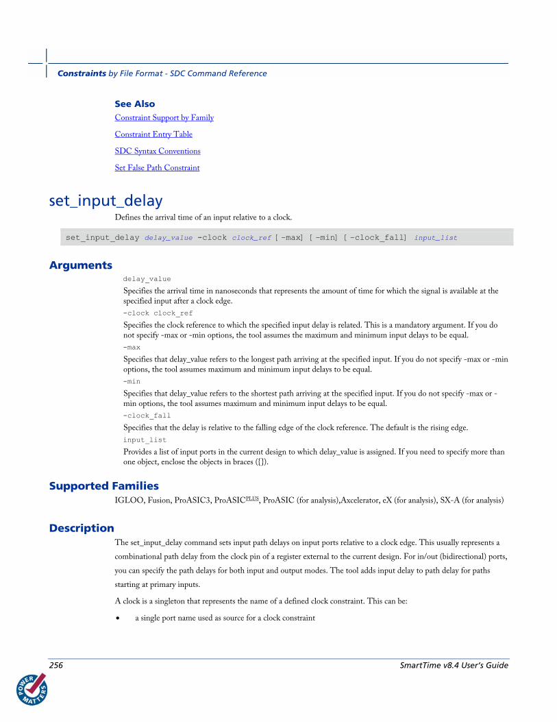
Constraints by File Format - SDC Command Reference
256 SmartTime v8.4 User’s Guide
See Also Constraint Support by Family
Constraint Entry Table
SDC Syntax Conventions
Set False Path Constraint
set_input_delay Defines the arrival time of an input relative to a clock.
set_input_delay delay_value -clock clock_ref [–max] [–min] [–clock_fall] input_list
Arguments delay_value
Specifies the arrival time in nanoseconds that represents the amount of time for which the signal is available at the specified input after a clock edge.
-clock clock_ref
Specifies the clock reference to which the specified input delay is related. This is a mandatory argument. If you do not specify -max or -min options, the tool assumes the maximum and minimum input delays to be equal.
-max
Specifies that delay_value refers to the longest path arriving at the specified input. If you do not specify -max or -min options, the tool assumes maximum and minimum input delays to be equal.
-min
Specifies that delay_value refers to the shortest path arriving at the specified input. If you do not specify -max or -min options, the tool assumes maximum and minimum input delays to be equal.
-clock_fall
Specifies that the delay is relative to the falling edge of the clock reference. The default is the rising edge.
input_list
Provides a list of input ports in the current design to which delay_value is assigned. If you need to specify more than one object, enclose the objects in braces ({}).
Supported Families IGLOO, Fusion, ProASIC3, ProASICPLUS, ProASIC (for analysis),Axcelerator, eX (for analysis), SX-A (for analysis)
Description The set_input_delay command sets input path delays on input ports relative to a clock edge. This usually represents a
combinational path delay from the clock pin of a register external to the current design. For in/out (bidirectional) ports,
you can specify the path delays for both input and output modes. The tool adds input delay to path delay for paths
starting at primary inputs.
A clock is a singleton that represents the name of a defined clock constraint. This can be:
• a single port name used as source for a clock constraint

set_load
SmartTime v8.4 User’s Guide 257
• a single pin name used as source for a clock constraint; for instance reg1:CLK. This name can be hierarchical (for
instance toplevel/block1/reg2:CLK)
• an object accessor that will refer to one clock: [get_clocks {clk}]
Examples The following example sets an input delay of 1.2ns for port data1 relative to the rising edge of CLK1:
set_input_delay 1.2 -clock [get_clocks CLK1] [get_ports data1]
The following example sets a different maximum and minimum input delay for port IN1 relative to the falling edge of
CLK2:
set_input_delay 1.0 -clock_fall -clock CLK2 –min {IN1}
set_input_delay 1.4 -clock_fall -clock CLK2 –max {IN1}
Actel Implementation Specifics • In SDC, the -clock is an optional argument that allows you to set input delay for combinational designs. Actel
implementation currently requires this argument.
See Also Constraint Support by Family
Constraint Entry Table
SDC Syntax Conventions
Set Input Delay
set_load Sets the load to a specified value on a specified port.
set_load capacitance port_list
Arguments capacitance
Specifies the capacitance value that must be set on the specified ports.
port_list
Specifies a list of ports in the current design on which the capacitance is to be set.
Supported Families IGLOO, Fusion, ProASIC3, Axcelerator, RTAX-S, eX, and SX-A
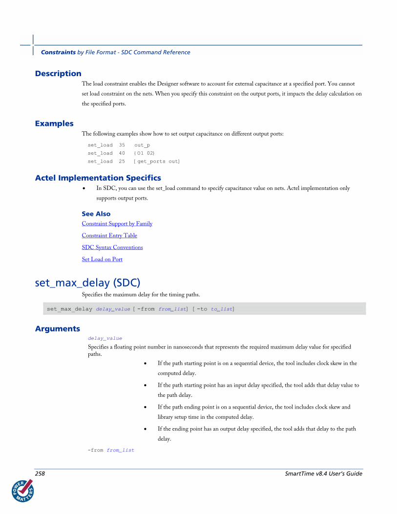
Constraints by File Format - SDC Command Reference
258 SmartTime v8.4 User’s Guide
Description The load constraint enables the Designer software to account for external capacitance at a specified port. You cannot
set load constraint on the nets. When you specify this constraint on the output ports, it impacts the delay calculation on
the specified ports.
Examples The following examples show how to set output capacitance on different output ports:
set_load 35 out_p
set_load 40 {O1 02}
set_load 25 [get_ports out]
Actel Implementation Specifics • In SDC, you can use the set_load command to specify capacitance value on nets. Actel implementation only
supports output ports.
See Also Constraint Support by Family
Constraint Entry Table
SDC Syntax Conventions
Set Load on Port
set_max_delay (SDC) Specifies the maximum delay for the timing paths.
set_max_delay delay_value [-from from_list] [-to to_list]
Arguments delay_value
Specifies a floating point number in nanoseconds that represents the required maximum delay value for specified paths.
• If the path starting point is on a sequential device, the tool includes clock skew in the
computed delay.
• If the path starting point has an input delay specified, the tool adds that delay value to
the path delay.
• If the path ending point is on a sequential device, the tool includes clock skew and
library setup time in the computed delay.
• If the ending point has an output delay specified, the tool adds that delay to the path
delay.
-from from_list
set_max_delay (SDC)
SmartTime v8.4 User’s Guide 259
Specifies a list of timing path starting points. A valid timing starting point is a clock, a primary input, an inout port, or a clock pin of a sequential cell.
-to to_list
Specifies a list of timing path ending points. A valid timing ending point is a clock, a primary output, an inout port, or a data pin of a sequential cell.
Supported Families IGLOO, Fusion, ProASIC3, ProASICPLUS, ProASIC (for analysis), Axcelerator, eX (-through option), SX-A (-
through option)
Description This command specifies the required maximum delay for timing paths in the current design. The path length for any
startpoint in from_list to any endpoint in to_list must be less than delay_value.
The tool automatically derives the individual maximum delay targets from clock waveforms and port input or output
delays. For more information, refer to the create_clock, set_input_delay, and set_output_delay commands.
The maximum delay constraint is a timing exception. This constraint overrides the default single cycle timing
relationship for one or more timing paths. This constraint also overrides a multicycle path constraint.
Examples The following example sets a maximum delay by constraining all paths from ff1a:CLK or ff1b:CLK to ff2e:D with a
delay less than 5 ns:
set_max_delay 5 -from {ff1a:CLK ff1b:CLK} -to {ff2e:D}
The following example sets a maximum delay by constraining all paths to output ports whose names start by “out” with
a delay less than 3.8 ns:
set_max_delay 3.8 -to [get_ports out*]
Actel Implementation Specifics • The –through option in the set_max_delay SDC command is not supported.
See Also Constraint Support by Family
Constraint Entry Table
SDC Syntax Conventions
Set Max Delay
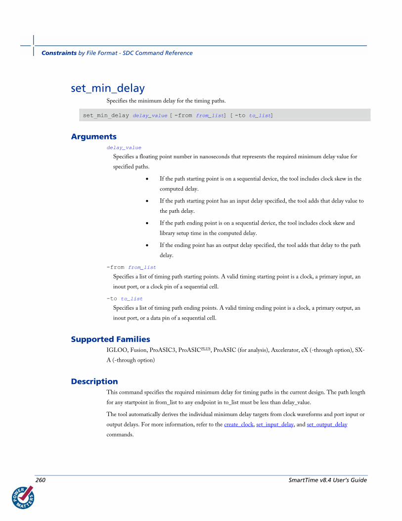
Constraints by File Format - SDC Command Reference
260 SmartTime v8.4 User’s Guide
set_min_delay Specifies the minimum delay for the timing paths.
set_min_delay delay_value [-from from_list] [-to to_list]
Arguments delay_value
Specifies a floating point number in nanoseconds that represents the required minimum delay value for
specified paths.
• If the path starting point is on a sequential device, the tool includes clock skew in the
computed delay.
• If the path starting point has an input delay specified, the tool adds that delay value to
the path delay.
• If the path ending point is on a sequential device, the tool includes clock skew and
library setup time in the computed delay.
• If the ending point has an output delay specified, the tool adds that delay to the path
delay.
-from from_list
Specifies a list of timing path starting points. A valid timing starting point is a clock, a primary input, an
inout port, or a clock pin of a sequential cell.
-to to_list
Specifies a list of timing path ending points. A valid timing ending point is a clock, a primary output, an
inout port, or a data pin of a sequential cell.
Supported Families IGLOO, Fusion, ProASIC3, ProASICPLUS, ProASIC (for analysis), Axcelerator, eX (-through option), SX-
A (-through option)
Description This command specifies the required minimum delay for timing paths in the current design. The path length
for any startpoint in from_list to any endpoint in to_list must be less than delay_value.
The tool automatically derives the individual minimum delay targets from clock waveforms and port input or
output delays. For more information, refer to the create_clock, set_input_delay, and set_output_delay
commands.
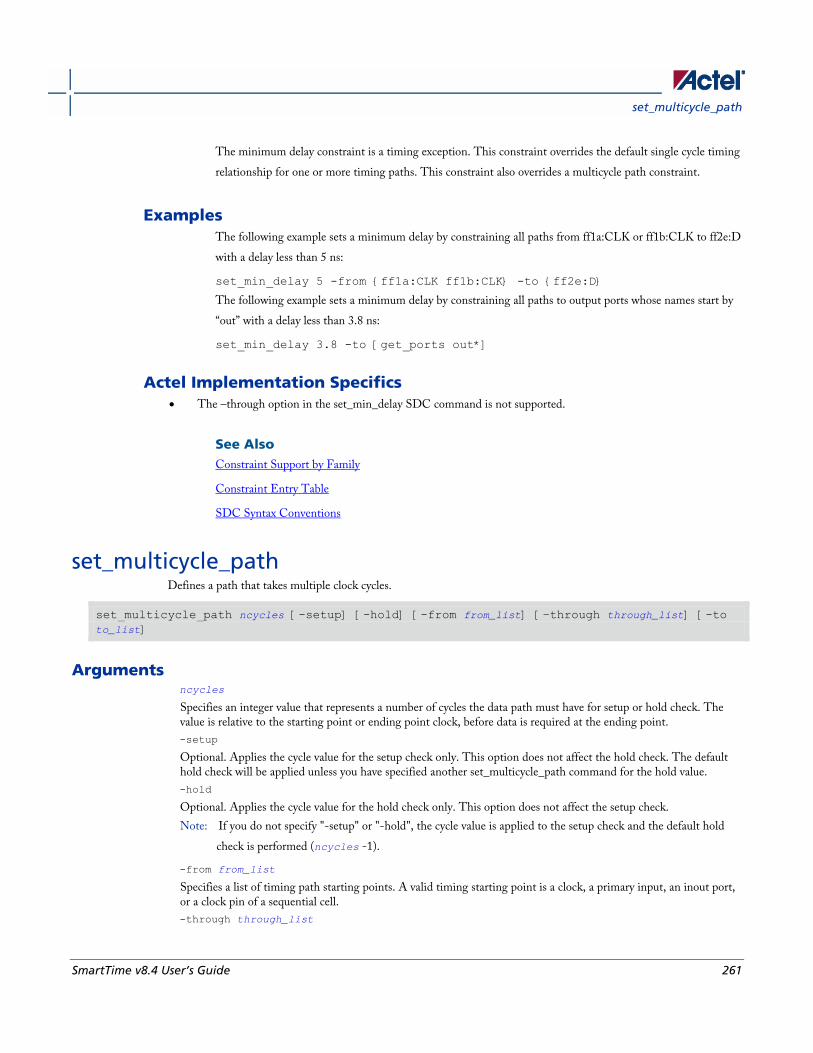
set_multicycle_path
SmartTime v8.4 User’s Guide 261
The minimum delay constraint is a timing exception. This constraint overrides the default single cycle timing
relationship for one or more timing paths. This constraint also overrides a multicycle path constraint.
Examples The following example sets a minimum delay by constraining all paths from ff1a:CLK or ff1b:CLK to ff2e:D
with a delay less than 5 ns:
set_min_delay 5 -from {ff1a:CLK ff1b:CLK} -to {ff2e:D}
The following example sets a minimum delay by constraining all paths to output ports whose names start by
“out” with a delay less than 3.8 ns:
set_min_delay 3.8 -to [get_ports out*]
Actel Implementation Specifics • The –through option in the set_min_delay SDC command is not supported.
See Also Constraint Support by Family
Constraint Entry Table
SDC Syntax Conventions
set_multicycle_path Defines a path that takes multiple clock cycles.
set_multicycle_path ncycles [-setup] [-hold] [-from from_list] [–through through_list] [-to to_list]
Arguments ncycles
Specifies an integer value that represents a number of cycles the data path must have for setup or hold check. The value is relative to the starting point or ending point clock, before data is required at the ending point.
-setup
Optional. Applies the cycle value for the setup check only. This option does not affect the hold check. The default hold check will be applied unless you have specified another set_multicycle_path command for the hold value.
-hold
Optional. Applies the cycle value for the hold check only. This option does not affect the setup check.
Note: If you do not specify "-setup" or "-hold", the cycle value is applied to the setup check and the default hold
check is performed (ncycles -1).
-from from_list
Specifies a list of timing path starting points. A valid timing starting point is a clock, a primary input, an inout port, or a clock pin of a sequential cell.
-through through_list

Constraints by File Format - SDC Command Reference
262 SmartTime v8.4 User’s Guide
Specifies a list of pins or ports through which the multiple cycle paths must pass.
-to to_list
Specifies a list of timing path ending points. A valid timing ending point is a clock, a primary output, an inout port, or a data pin of a sequential cell.
Supported Families IGLOO, fFusion, ProASIC3, ProASICPLUS, ProASIC (for analysis), Axcelerator, eX (for analysis), SX-A (for
analysis)
Description Setting multiple cycle paths constraint overrides the single cycle timing relationships between sequential elements by
specifying the number of cycles that the data path must have for setup or hold checks. If you change the multiplier, it
affects both the setup and hold checks.
False path information always takes precedence over multiple cycle path information. A specific maximum delay
constraint overrides a general multiple cycle path constraint.
If you specify more than one object within one -through option, the path passes through any of the objects.
Examples The following example sets all paths between reg1 and reg2 to 3 cycles for setup check. Hold check is measured at the
previous edge of the clock at reg2.
set_multicycle_path 3 -from [get_pins {reg1}] –to [get_pins {reg2}]
The following example specifies that four cycles are needed for setup check on all paths starting at the registers in the
clock domain ck1. Hold check is further specified with two cycles instead of the three cycles that would have been
applied otherwise.
set_multicycle_path 4 -setup -from [get_clocks {ck1}]
set_multicycle_path 2 -hold -from [get_clocks {ck1}]
Actel Implementation Specifics • SDC allows multiple priority management on the multiple cycle path constraint depending on the scope of the
object accessors. In Actel design implementation, such priority management is not supported. All multiple cycle
path constraints are handled with the same priority.
See Also Constraint Support by Family
Constraint Entry Table
SDC Syntax Conventions
Set Multicycle Path

set_output_delay
SmartTime v8.4 User’s Guide 263
set_output_delay Defines the output delay of an output relative to a clock.
set_output_delay delay_value -clock clock_ref [–max] [–min] [–clock_fall] output_list
Arguments delay_value
Specifies the amount of time before a clock edge for which the signal is required. This represents a combinational path delay to a register outside the current design plus the library setup time (for maximum output delay) or hold time (for minimum output delay).
-clock clock_ref
Specifies the clock reference to which the specified output delay is related. This is a mandatory argument. If you do not specify -max or -min options, the tool assumes the maximum and minimum input delays to be equal.
-max
Specifies that delay_value refers to the longest path from the specified output. If you do not specify -max or -min options, the tool assumes the maximum and minimum output delays to be equal.
-min
Specifies that delay_value refers to the shortest path from the specified output. If you do not specify -max or -min options, the tool assumes the maximum and minimum output delays to be equal.
-clock_fall
Specifies that the delay is relative to the falling edge of the clock reference. The default is the rising edge.
output_list
Provides a list of output ports in the current design to which delay_value is assigned. If you need to specify more than one object, enclose the objects in braces ({}).
Supported Families IGLOO, Fusion, ProASIC3, ProASICPLUS, ProASIC (for analysis), Axcelerator, eX (for analysis), SX-A (for analysis)
Description The set_output_delay command sets output path delays on output ports relative to a clock edge. Output ports have no
output delay unless you specify it. For in/out (bidirectional) ports, you can specify the path delays for both input and
output modes. The tool adds output delay to path delay for paths ending at primary outputs.
Examples The following example sets an output delay of 1.2ns for port OUT1 relative to the rising edge of CLK1:
set_output_delay 1.2 -clock [get_clocks CLK1] [get_ports OUT1]
The following example sets a different maximum and minimum output delay for port OUT1 relative to the falling edge
of CLK2:
set_output_delay 1.0 -clock_fall -clock CLK2 –min {OUT1}
set_output_delay 1.4 -clock_fall -clock CLK2 –max {OUT1}
Constraints by File Format - SDC Command Reference
264 SmartTime v8.4 User’s Guide
Actel Implementation Specifics • In SDC, the -clock is an optional argument that allows you to set the output delay for combinational designs.
Actel implementation currently requires this option.
See Also Constraint Support by Family
Constraint Entry Table
SDC Syntax Conventions
Set Output Delay
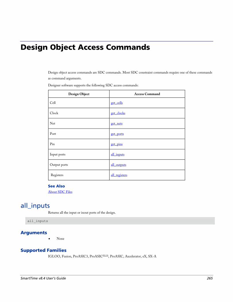
SmartTime v8.4 User’s Guide 265
Design Object Access Commands
Design object access commands are SDC commands. Most SDC constraint commands require one of these commands
as command arguments.
Designer software supports the following SDC access commands:
Design Object Access Command
Cell get_cells
Clock get_clocks
Net get_nets
Port get_ports
Pin get_pins
Input ports all_inputs
Output ports all_outputs
Registers all_registers
See Also About SDC Files
all_inputs Returns all the input or inout ports of the design.
all_inputs
Arguments • None
Supported Families IGLOO, Fusion, ProASIC3, ProASICPLUS, ProASIC, Axcelerator, eX, SX-A
Design Object Access Commands
266 SmartTime v8.4 User’s Guide
Exceptions • None
Example set_max_delay -from [all_inputs] -to [get_clocks ck1]
Actel Implementation Specifics • None
See Also Constraint Support by Family
Constraint Entry Table
SDC Syntax Conventions
all_registers Returns either a collection of register cells or register pins, whichever you specify.
all_registers [-clock clock_name] [-cells] [-data_pins ] [-clock_pins] [-async_pins] [-output_pins]
Arguments -clock clock_name
Creates a collection of register cells or register pins in the specified clock domain.
-cells
Creates a collection of register cells. This is the default. This option cannot be used in combination with any other option.
-data_pins
Creates a collection of register data pins.
-clock_pins
Creates a collection of register clock pins.
-async_pins
Creates a collection of register asynchronous pins.
-output_pins
Creates a collection of register output pins.
Supported Families IGLOO, Fusion, ProASIC3, ProASICPLUS, ProASIC, Axcelerator, eX, SX-A
Description This command creates either a collection of register cells (default) or register pins, whichever is specified. If you do not
specify an option, this command creates a collection of register cells.
all_registers
SmartTime v8.4 User’s Guide 267
Exceptions • None
Examples set_max_delay 2 -from [all_registers] -to [get_ports {out}]
set_max_delay 3 –to [all_registers –async_pins]
set_false_path –from [all_registers –clock clk150]
set_multicycle_path –to [all_registers –clock c* -data_pins
–clock_pins]
Actel Implementation Specifics • None
See Also Constraint Support by Family
Constraint Entry Table
SDC Syntax Conventions
all_registers Returns either a collection of register cells or register pins, whichever you specify.
all_registers [-clock clock_name] [-cells] [-data_pins ] [-clock_pins] [-async_pins] [-output_pins]
Arguments -clock clock_name
Creates a collection of register cells or register pins in the specified clock domain.
-cells
Creates a collection of register cells. This is the default. This option cannot be used in combination with any other option.
-data_pins
Creates a collection of register data pins.
-clock_pins
Creates a collection of register clock pins.
-async_pins
Creates a collection of register asynchronous pins.
-output_pins
Creates a collection of register output pins.
Supported Families IGLOO, Fusion, ProASIC3, ProASICPLUS, ProASIC, Axcelerator, eX, SX-A
Design Object Access Commands
268 SmartTime v8.4 User’s Guide
Description This command creates either a collection of register cells (default) or register pins, whichever is specified. If you do not
specify an option, this command creates a collection of register cells.
Exceptions • None
Examples set_max_delay 2 -from [all_registers] -to [get_ports {out}]
set_max_delay 3 –to [all_registers –async_pins]
set_false_path –from [all_registers –clock clk150]
set_multicycle_path –to [all_registers –clock c* -data_pins
–clock_pins]
Actel Implementation Specifics • None
See Also Constraint Support by Family
Constraint Entry Table
SDC Syntax Conventions
get cells Returns the cells (instances) specified by the pattern argument.
get_cells pattern
Arguments pattern
Specifies the pattern to match the instances to return. For example, "get_cells U18*" returns all instances starting with the characters "U18", where “*” is a wildcard that represents any character string.
Supported Families IGLOO, Fusion, ProASIC3, Axcelerator, RTAX-S, eX, and SX-A
Description This command returns a collection of instances matching the pattern you specify. You can only use this command as
part of a –from, -to, or –through argument for the following constraint exceptions: set_max delay, set_multicycle_path,
and set_false_path design constraints.
get_clocks
SmartTime v8.4 User’s Guide 269
Exceptions • None
Examples set_max_delay 2 -from [get_cells {reg*}] -to [get_ports {out}]
set_false_path –through [get_cells {Rblock/muxA}]
Actel Implementation Specifics • None
See Also Constraint Support by Family
Constraint Entry Table
SDC Syntax Conventions
get_clocks Returns the specified clock.
get_clocks pattern
Arguments pattern
Specifies the pattern to match to the Timer or SmartTime on which a clock constraint has been set.
Supported Families IGLOO, Fusion, ProASIC3, Axcelerator, RTAX-S, eX, and SX-A
Description • If this command is used as a –from argument in maximum delay (set_max_path_delay), false path
(set_false_path), and multicycle constraints (set_multicycle_path), the clock pins of all the registers related to this
clock are used as path start points.
• If this command is used as a –to argument in maximum delay (set_max_path_delay), false path (set_false_path),
and multicycle constraints (set_multicycle_path), the synchronous pins of all the registers related to this clock are
used as path endpoints.
Exceptions • None
Design Object Access Commands
270 SmartTime v8.4 User’s Guide
Example set_max_delay -from [get_ports datal] -to \
[get_clocks ck1]
Actel Implementation Specifics • None
See Also Constraint Support by Family
Constraint Entry Table
SDC Syntax Conventions
get_pins Returns the specified pins.
get_pins pattern
Arguments pattern
Specifies the pattern to match the pins.
Supported Families IGLOO, Fusion, ProASIC3, Axcelerator, RTAX-S, eX, and SX-A
Exceptions • None
Example create_clock -period 10 [get_pins clock_gen/reg2:Q]
Actel Implementation Specifics • None
See Also Constraint Support by Family
Constraint Entry Table
SDC Syntax Conventions
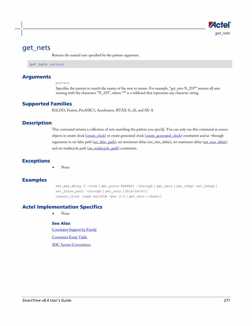
get_nets
SmartTime v8.4 User’s Guide 271
get_nets Returns the named nets specified by the pattern argument.
get_nets pattern
Arguments pattern
Specifies the pattern to match the names of the nets to return. For example, "get_nets N_255*" returns all nets starting with the characters "N_255", where “*” is a wildcard that represents any character string.
Supported Families IGLOO, Fusion, ProASIC3, Axcelerator, RTAX-S, eX, and SX-A
Description This command returns a collection of nets matching the pattern you specify. You can only use this command as source
objects in create clock (create_clock) or create generated clock (create_generated_clock) constraints and as -through
arguments in set false path (set_false_path), set minimum delay (set_min_delay), set maximum delay (set_max_delay),
and set multicycle path (set_multicycle_path) constraints.
Exceptions • None
Examples set_max_delay 2 -from [get_ports RDATA1] -through [get_nets {net_chkp1 net_chkqi}]
set_false_path –through [get_nets {Tblk/rm/n*}]
create_clcok -name mainCLK -per 2.5 [get_nets {cknet}]
Actel Implementation Specifics • None
See Also Constraint Support by Family
Constraint Entry Table
SDC Syntax Conventions
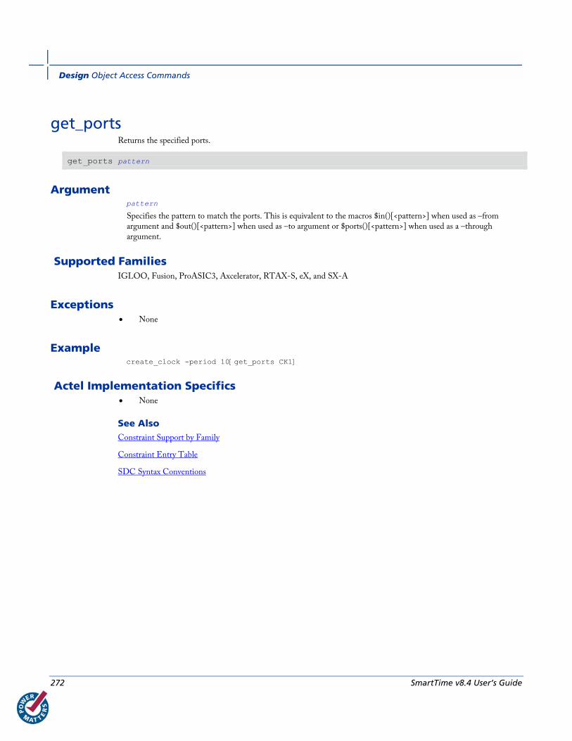
Design Object Access Commands
272 SmartTime v8.4 User’s Guide
get_ports Returns the specified ports.
get_ports pattern
Argument pattern
Specifies the pattern to match the ports. This is equivalent to the macros $in()[<pattern>] when used as –from argument and $out()[<pattern>] when used as –to argument or $ports()[<pattern>] when used as a –through argument.
Supported Families IGLOO, Fusion, ProASIC3, Axcelerator, RTAX-S, eX, and SX-A
Exceptions • None
Example create_clock -period 10[get_ports CK1]
Actel Implementation Specifics • None
See Also Constraint Support by Family
Constraint Entry Table
SDC Syntax Conventions
SmartTime v8.4 User’s Guide 273
Glossary
arrival time Actual time in nanoseconds at which the data arrives at a sink pin when considering the propagation delays across the
path.
asynchronous Two signals that are not related to each other. Signals not related to the clock are usually asynchronous.
capture edge The clock edge that triggers the capture of data at the end point of a path.
clock A periodic signal that captures data into sequential elements.
critical path A path with the maximum delay between a starting point and an end point. In the presence of a clock constraint, the
worst critical path between registers in this clock domain is the path with the worst slack.
dynamic timing analysis The standard method for verifying design functionality and performance. Both pre-layout and post-layout timing
analysis can be performed via the SDF interface.
exception See timing exception.
explicit clock Clock sources that can be traced back unambiguously from the clock pin of the registers they deserve, including the
output of a DLL or PLL.
filter A set of limitations applied to object names in timing analysis to generate target specific sets.
launch edge The clock edge that triggers the release of data from a starting point to be captured by another clock edge at an end
point.
Glossary
274 SmartTime v8.4 User’s Guide
minimum period Timing characteristic of a path between two registers. It indicates how fast the clock will run when this path is the most
critical one. The minimum period value takes into consideration both the skew and the setup on the receiving register.
parallel paths Paths that run in parallel between a given source and sink pair.
path A sequence of elements in the design that identifies a logical flow starting at a source pin and ending at a sink pin.
path details An expansion of the path that shows all the nets and cells between the source pin and the sink pin.
path set A collection of paths.
paths list Same as path set.
post-layout The state of the design after you run Layout. In post-layout, the placement and routing information are available for
the whole design.
potential clock Pins or ports connected to the clock pins of sequential elements that the Static Timing Analysis (STA) tool cannot
determine whether they are is enabled sources or clock sources. This type of clock is generally associated with the use of
gated clocks.
pre-layout The state of the design before you run Layout. In pre-layout, the placement and routing information are not available.
recovery time The amount of time before the active clock edge when the de-activation of asynchronous signals is not allowed.
removal time The amount of time after the active clock edge when the de-activation of asynchronous signals is not allowed.
get_ports
SmartTime v8.4 User’s Guide 275
required time The time at which the data must be at a sink pin to avoid being in violation.
requirement See timing requirement.
scenario (timing constraints scenario) Set of timing constraints defined by the user.
setup time The time in nanoseconds relative to a clock edge during which the data at the input to a sequential element must
remain stable.
sink pin The pin located at the end of the timing path. This pin is usually the one where arrival time and required time are
evaluated for path violation.
skew The difference between the clock insertion delay to the clock pin of a sink register and the insertion delay to the clock
pin of a source register.
slack The difference between the arrival time and the required time at a specific pin, generally at the data pin of a sequential
component.
slew rate The time needed for a signal to transition from one logic level to another.
source pin The pin located at the beginning of a timing path.
STA See static timing analysis.
standard delay format (SDF) Standard Delay Format, a standard file format used to store design data suited for back-annotation.
Glossary
276 SmartTime v8.4 User’s Guide
static timing analysis An efficient technique to identify timing violations in a design and to ensure that all timing requirements are met. It is
well suited for traditional synchronous designs. The main advantages are that it does not require input vectors, and it
exclusively covers all possible paths in the design in a relatively short run-time.
synopsys design constraint (SDC) A standard file format for timing constraints. Synopsys Design Constraints (SDC) is a Tcl-based format used by
Synopsys tools to specify the design intent, including the timing and area constraints for a design. Actel tools use a
subset of the SDC format to capture supported timing constraints. You can import or export an SDC file from the
Designer software. Any timing constraint that you can enter using Designer tools, can also be specified in an SDC file.
timing constraint A requirement or limitation on the design to be satisfied during the design implementation.
timing exception An exception to a general requirement usually applied on a subset of the objects on which the requirement is applied.
timing requirement A constraint on the design usually determined by the specifications at the system level.
virtual clock A virtual clock is a clock with no source associated to it. It is used to describe clocks outside the FPGA that have an
impact on the timing analysis inside the FPGA. For example, if the I/Os are synchronous to an external clock.
WLM Wire Load Model. A timing model used in pre-layout to estimate a net delay based on the fan-out.
SmartTime v8.4 User’s Guide 277
Product Support
Actel backs its products with various support services including Customer Service, a Customer Technical Support Center, a web site, an FTP site, electronic mail, and worldwide sales offices. This appendix contains information about contacting Actel and using these support services.
Customer Service Contact Customer Service for non-technical product support, such as product pricing, product upgrades, update information, order status, and authorization.
From Northeast and North Central U.S.A., call 650.318.4480 From Southeast and Southwest U.S.A., call 650. 318.4480 From South Central U.S.A., call 650.318.4434 From Northwest U.S.A., call 650.318.4434 From Canada, call 650.318.4480 From Europe, call 650.318.4252 or +44 (0) 1276 401 500 From Japan, call 650.318.4743 From the rest of the world, call 650.318.4743 Fax, from anywhere in the world 650. 318.8044
Actel Customer Technical Support Center Actel staffs its Customer Technical Support Center with highly skilled engineers who can help answer your hardware, software, and design questions. The Customer Technical Support Center spends a great deal of time creating application notes and answers to FAQs. So, before you contact us, please visit our online resources. It is very likely we have already answered your questions.
Actel Technical Support Visit the Actel Customer Support website (http://www.actel.com/custsup/search.html) for more information and support. Many answers available on the searchable web resource include diagrams, illustrations, and links to other resources on the Actel web site.
Website You can browse a variety of technical and non-technical information on Actel’s home page, at http://www.actel.com/.
Contacting the Customer Technical Support Center Highly skilled engineers staff the Technical Support Center from 7:00 A.M. to 6:00 P.M., Pacific Time, Monday through Friday. Several ways of contacting the Center follow:
Email You can communicate your technical questions to our email address and receive answers back by email, fax, or phone. Also, if you have design problems, you can email your design files to receive assistance. We constantly monitor the email account throughout the day. When sending your request to us, please be sure to include your full name, company name, and your contact information for efficient processing of your request.
Glossary
278 SmartTime v8.4 User’s Guide
The technical support email address is [email protected].
Phone Our Technical Support Center answers all calls. The center retrieves information, such as your name, company name, phone number and your question, and then issues a case number. The Center then forwards the information to a queue where the first available application engineer receives the data and returns your call. The phone hours are from 7:00 A.M. to 6:00 P.M., Pacific Time, Monday through Friday. The Technical Support numbers are:
650.318.4460 800.262.1060 Customers needing assistance outside the US time zones can either contact technical support via email ([email protected]) or contact a local sales office. Sales office listings can be found at www.actel.com/contact/offices/index.html.


For more information about Actel’s products, visit our website at
www.actel.com
Actel Corporation • 2061 Stierlin Court • Mountain View, CA 94043 • USA Phone 650.318.4200 • Fax 650.318.4600 • Customer Service: 650.318.1010 • Customer Applications Center: 800.262.1060 Actel Europe Ltd. • River Court, Meadows Business Park • Station Approach, Blackwater • Camberley Surrey GU17 9AB • United Kingdom Phone +44 (0) 1276 609 300 • Fax +44 (0) 1276 607 540 Actel Japan • EXOS Ebisu Building 4F • 1-24-14 Ebisu Shibuya-ku • Tokyo 150 • Japan Phone +81.03.3445.7671 • Fax +81.03.3445.7668 • http://jp.actel.com Actel Hong Kong • Room 2107, China Resources Building • 26 Harbour Road • Wanchai • Hong Kong Phone +852 2185 6460 • Fax +852 2185 6488 • www.actel.com.cn
50200049-10/7.08


![Metallic Electromigration Phenomena - Digchipapplication-notes.digchip.com/166/166-47937.pdfgrowth. (From [8].) When a filament finally bridges the gap between conductors, a sudden](https://img.pdfslide.us/doc/110x75/5ea91ad7bf50921a6b222985/metallic-electromigration-phenomena-digchipapplication-notes-growth-from-8.jpg)