Embed Size (px)
Citation preview

LP55281 Evaluation Kit National SemiconductorAN-1631Sami KotijarviJune 2007
LP55281 OverviewLP55281 is a quad RGB LED driver for handheld devices. Itcan drive 4 RGB LED sets and a single fun light LED. Theboost DC-DC converter drives high current loads with highefficiency. The RGB driver can drive individual color LEDs orRGB LEDs powered from boost output or external supply.Built-in audio synchronization feature allows easy control ofLP55281. Small micro SMD package or micro SMDxt pack-age together with minimum number of external componentsis a best fit for handheld devices. LP55281 has also a LEDtest feature, which can be used for example in production forchecking the LED connections.
Evaluation Kit OverviewLP55281 Evaluation Kit is based on a modular system, wherethe actual evaluation board is plugged on top of the PC inter-face board. The interface operates through the USB port.
The kit supports complete functional evaluation of the circuit.The evaluation kit consists of:
• LP55281 evaluation board
• USB interface board
• USB interface cable
• Audio cable and 3.5mm branch plug
• CD including:
— Evaluation software for PC
— LP55281 datasheet
— MicroSMD package application note AN1112
— MicroSMDxt package application note AN1412
— PCB design application note AN1149
— Evaluation kit document (this doc.)
30019515
Figure 1. LP55281 Evaluation Board With USB Interface Board
© 2007 National Semiconductor Corporation 300195 www.national.com
LP
55281 E
valu
atio
n K
itA
N-1
631

Evaluation SoftwareLP55281 evaluation software and some support files are sup-plied on the delivery CD together with all available documen-tation regarding the circuit. You can copy the software and thefiles to your PC’s hard disk. The program and the support filesmust be in the same folder. The software is started by double-clicking its icon. The software does not require any installa-tion.
This document describes the use of the LP55281.exe pro-gram.
The evaluation software is organized in tabs according to themain functions of the chip. On the left side of the tabs is shown
the whole register map of LP55281. Below the tabs are shownthe registers, which are affected by the selected tab. Bothregister displays reflect immediately the changes you makeby clicking the selection boxes or sliders in the tabs. The con-tents of the tabs should be mostly self-explanatory. Oneexample register settings are included in the delivery CD andthey can be loaded from the File/Open menu. You can simi-larly save your own settings.
30019502
Figure 2. LP55281 Evaluation Software User Interface
www.national.com 2
AN
-1631

COMMON TAB
30019510
Figure 3. LP55281 Common TabThe Common Tab contains evaluation board control func-tions. Automatic writing (Update registers immediately) isenabled by default. It means that a write operation is doneafter every mouse click. If you want to change several settingsin one or more tabs and write the register(s) after making allthe changes, you can disable automatic writing. Then afterthe changes you have to initiate the register write by clickingthe right mouse key with the cursor in the Register Map area.From the pop-up menu you can choose to write all registersor just a selected register. The same pop-up lets you writedefault values to one or all registers and read one or all reg-isters.
Interface can be selected between I2C and SPI. For I2C thereare two addresses available, 0x4C and 0x4D. Interface portis always USB.
The regulated voltage supplied from the USB board can beset to 3.0 or 3.9V. The raw voltage from the USB port is 5V
and maximum current is 500mA. By changing jumper J1 onthe USB board to 5V position the raw voltage is connectedto the evaluation board and power from USB board can bemaximally used for LEDs.
USB board can measure voltages from the evaluation board.On the LP55281 board the circuit VDDIO and the converteroutput voltage VBOOST are measured. The current supplied bythe USB board to the evaluation board is measured. Mea-surement is enabled, when the Polling interval in the Commontab is set. Measurement results are shown on top of the win-dow.
Device can be reset by hard reset or by soft reset. Soft resetwrites to register 0x60.
By checking the debug mode you can write or read data di-rectly to or from addresses given in Direct Access field.
3 www.national.com
AN
-1631

BOOST TAB
30019503
Figure 4. Boost Tab
Boost is enabled in this tab by checking the boost enable. Theinternal active load can be enabled to eliminate pulse skippingof the boost converter. Active load will consume some powerwhen the boost output current is small. It will decrease effi-
ciency at very light load conditions. Also the boost PWMfrequency and output voltage is set here. One can also enablethe Boost internal active load.
www.national.com 4
AN
-1631

COLOR LEDS TAB
30019514
Figure 5. Color LEDs TabFor each RGB LED, there is its own subtab in the Color LEDstab. In each subtab (RGB1-4) you can enable the RGB, setits PWM with the slider and select its current from the drop-down menu.
The Max current selection can be used to show the requiredcurrent set resistor value for a given LED current. It doesn'tcontrol the current in any way.
The PWM frequency can be controlled in this tab also.
5 www.national.com
AN
-1631

LED TEST, ALED AND AUDIO SYNCHRONIZATION TAB
30019504
Figure 6. LED Test, ALED and Audio Sync. TabIn this tab LED test, ALED and Audio Sync. is controlled.
LED test can be done automatically with LED Auto Test bypushing Start button. Test will go thru all the leds and indicateif they are connected or not. LED test can be done by usingADC also. Test is enabled by checking the Test enable box.Desired LED is chosen from pull-down menu and value canbe read by pushing the Read ADC button. Note that LED testwill not work correctly unless the PWM of the LED under testis 100%. Also the LED current should be at minimum.
ALED current is controlled with Current slider. Below the slid-er is the Audio synchronization enable box, which sets theALED into Audio Sync. mode.
With audio synchronization controls, you can enable the Au-tomatic Gain Control, set gain control level manually, selectSpeed from pull-down menu, select DC filter between 80 Hzor 510 Hz and set the Threshold.
www.national.com 6
AN
-1631

LED TEST TAB
30019505
Figure 7. LED Test TabIn LED test tab all the LEDs are tested with one press of abutton. You can set Boost voltage, RGB 1-4 currents andALED current. After pressing Start, test program automati-cally tests all the LEDs and Boost voltage. Results are dis-played on a table with ADC code, both in HEX and in DEC,voltages and forward voltages for the LEDs.
After performing the LED test, the device is reset and have tobe put to active mode again. Also the boost is disabled. TheRGB LEDs PWM value is set to 100%, RGB current values,ALED current and Boost voltage are set as you have chosen.
7 www.national.com
AN
-1631

HISTORY TAB
30019506
Figure 8. History TabThe History Tab records the command sequence of your ses-sion. You can copy-paste this information to another applica-tion if you wish.
www.national.com 8
AN
-1631
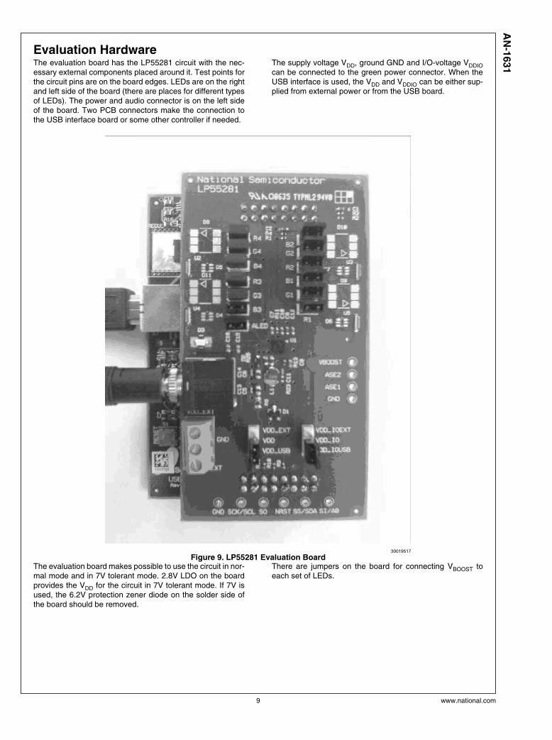
Evaluation HardwareThe evaluation board has the LP55281 circuit with the nec-essary external components placed around it. Test points forthe circuit pins are on the board edges. LEDs are on the rightand left side of the board (there are places for different typesof LEDs). The power and audio connector is on the left sideof the board. Two PCB connectors make the connection tothe USB interface board or some other controller if needed.
The supply voltage VDD, ground GND and I/O-voltage VDDIOcan be connected to the green power connector. When theUSB interface is used, the VDD and VDDIO can be either sup-plied from external power or from the USB board.
30019517
Figure 9. LP55281 Evaluation BoardThe evaluation board makes possible to use the circuit in nor-mal mode and in 7V tolerant mode. 2.8V LDO on the boardprovides the VDD for the circuit in 7V tolerant mode. If 7V isused, the 6.2V protection zener diode on the solder side ofthe board should be removed.
There are jumpers on the board for connecting VBOOST toeach set of LEDs.
9 www.national.com
AN
-1631

USB InterfaceThe USB interface forms the connection between the PC andthe evaluation system. It converts the commands from PC toI2C or SPI format. It also provides adjustable supply voltagefor the evaluation board and makes possible to measure se-lected voltages and the input current in the evaluation board.
THE USB INTERFACE FIRMWARE
The USB interface checks for the firmware version of the USBboard when the evaluation software is started. If the firmwareneeds updating, the software prompts you to allow automaticupdate.
30019508
Figure 10. USB Interface Board
www.national.com 10
AN
-1631

Getting StartedThe following instructions show how to use the LP55281 eval-uation kit in default conditions with the USB interface board.Please use the ESD protection (ground cable) to prevent anyunwanted damaging ESD events.
1. Check the jumpers and switches on the board.
2. Plug in the evaluation board to the USB board. Connectthe USB cable to the evaluation board and to the USBport of your PC. When you plug in the USB board for thefirst time, your operating system prompts you about “Newhardware found” and installs the USB driver. With Win95and Win98 operating systems you have to accept theinstallation and click “Next” several times as theinstallation proceeds.
3. Copy the evaluation software and the support files to yourPC’s hard disk. Start the software by double-clicking itsicon.
4. Press Hardware Reset and USB Setup buttons to resetthe chip and the USB interface board.
5. Turn on the chip and the boost converter by enablingstand-by and boost.
6. The Evaluation Kit is now ready to use and the chip canbe controlled through the PC-software.
You should disconnect the USB cable from the computer al-ways, when plugging in or removing the evaluation board fromthe interface board and also when changing the supplyjumper settings. Otherwise the USB board may stop respond-ing.
If the USB board is not responding or the software hangs up,press the reset button on the USB board, or disconnect theUSB cable for 5 seconds.
If the evaluation software notices that the firmware on theUSB board needs to be updated, the software can proposeautomatic firmware updating. The new firmware will be in-cluded in the evaluation kit software.
11 www.national.com
AN
-1631

Schematics of The Evaluation Board
30019509
Fig
ure
11
. L
P5
52
81
Ev
alu
ati
on
Bo
ard
Sc
he
ma
tic
www.national.com 12
AN
-1631
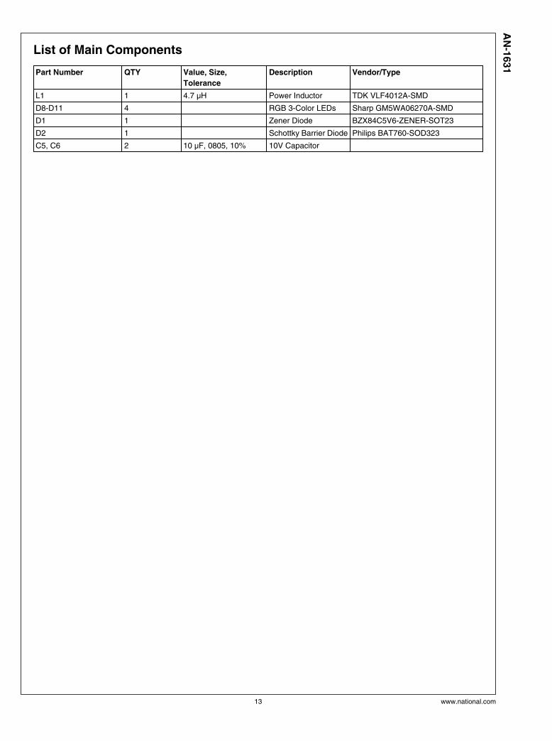
List of Main Components
Part Number QTY Value, Size,
Tolerance
Description Vendor/Type
L1 1 4.7 µH Power Inductor TDK VLF4012A-SMD
D8-D11 4 RGB 3-Color LEDs Sharp GM5WA06270A-SMD
D1 1 Zener Diode BZX84C5V6-ZENER-SOT23
D2 1 Schottky Barrier Diode Philips BAT760-SOD323
C5, C6 2 10 µF, 0805, 10% 10V Capacitor
13 www.national.com
AN
-1631

NotesA
N-1
631
LP
55281 E
valu
ati
on
Kit
THE CONTENTS OF THIS DOCUMENT ARE PROVIDED IN CONNECTION WITH NATIONAL SEMICONDUCTOR CORPORATION(“NATIONAL”) PRODUCTS. NATIONAL MAKES NO REPRESENTATIONS OR WARRANTIES WITH RESPECT TO THE ACCURACYOR COMPLETENESS OF THE CONTENTS OF THIS PUBLICATION AND RESERVES THE RIGHT TO MAKE CHANGES TOSPECIFICATIONS AND PRODUCT DESCRIPTIONS AT ANY TIME WITHOUT NOTICE. NO LICENSE, WHETHER EXPRESS,IMPLIED, ARISING BY ESTOPPEL OR OTHERWISE, TO ANY INTELLECTUAL PROPERTY RIGHTS IS GRANTED BY THISDOCUMENT.
TESTING AND OTHER QUALITY CONTROLS ARE USED TO THE EXTENT NATIONAL DEEMS NECESSARY TO SUPPORTNATIONAL’S PRODUCT WARRANTY. EXCEPT WHERE MANDATED BY GOVERNMENT REQUIREMENTS, TESTING OF ALLPARAMETERS OF EACH PRODUCT IS NOT NECESSARILY PERFORMED. NATIONAL ASSUMES NO LIABILITY FORAPPLICATIONS ASSISTANCE OR BUYER PRODUCT DESIGN. BUYERS ARE RESPONSIBLE FOR THEIR PRODUCTS ANDAPPLICATIONS USING NATIONAL COMPONENTS. PRIOR TO USING OR DISTRIBUTING ANY PRODUCTS THAT INCLUDENATIONAL COMPONENTS, BUYERS SHOULD PROVIDE ADEQUATE DESIGN, TESTING AND OPERATING SAFEGUARDS.
EXCEPT AS PROVIDED IN NATIONAL’S TERMS AND CONDITIONS OF SALE FOR SUCH PRODUCTS, NATIONAL ASSUMES NOLIABILITY WHATSOEVER, AND NATIONAL DISCLAIMS ANY EXPRESS OR IMPLIED WARRANTY RELATING TO THE SALEAND/OR USE OF NATIONAL PRODUCTS INCLUDING LIABILITY OR WARRANTIES RELATING TO FITNESS FOR A PARTICULARPURPOSE, MERCHANTABILITY, OR INFRINGEMENT OF ANY PATENT, COPYRIGHT OR OTHER INTELLECTUAL PROPERTYRIGHT.
LIFE SUPPORT POLICY
NATIONAL’S PRODUCTS ARE NOT AUTHORIZED FOR USE AS CRITICAL COMPONENTS IN LIFE SUPPORT DEVICES ORSYSTEMS WITHOUT THE EXPRESS PRIOR WRITTEN APPROVAL OF THE CHIEF EXECUTIVE OFFICER AND GENERALCOUNSEL OF NATIONAL SEMICONDUCTOR CORPORATION. As used herein:
Life support devices or systems are devices which (a) are intended for surgical implant into the body, or (b) support or sustain life andwhose failure to perform when properly used in accordance with instructions for use provided in the labeling can be reasonably expectedto result in a significant injury to the user. A critical component is any component in a life support device or system whose failure to performcan be reasonably expected to cause the failure of the life support device or system or to affect its safety or effectiveness.
National Semiconductor and the National Semiconductor logo are registered trademarks of National Semiconductor Corporation. All otherbrand or product names may be trademarks or registered trademarks of their respective holders.
Copyright© 2007 National Semiconductor Corporation
For the most current product information visit us at www.national.com
National SemiconductorAmericas CustomerSupport CenterEmail:[email protected]: 1-800-272-9959
National Semiconductor EuropeCustomer Support CenterFax: +49 (0) 180-530-85-86Email: [email protected] Tel: +49 (0) 69 9508 6208English Tel: +49 (0) 870 24 0 2171Français Tel: +33 (0) 1 41 91 8790
National Semiconductor AsiaPacific Customer Support CenterEmail: [email protected]
National Semiconductor JapanCustomer Support CenterFax: 81-3-5639-7507Email: [email protected]: 81-3-5639-7560
www.national.com