Embed Size (px)
Citation preview
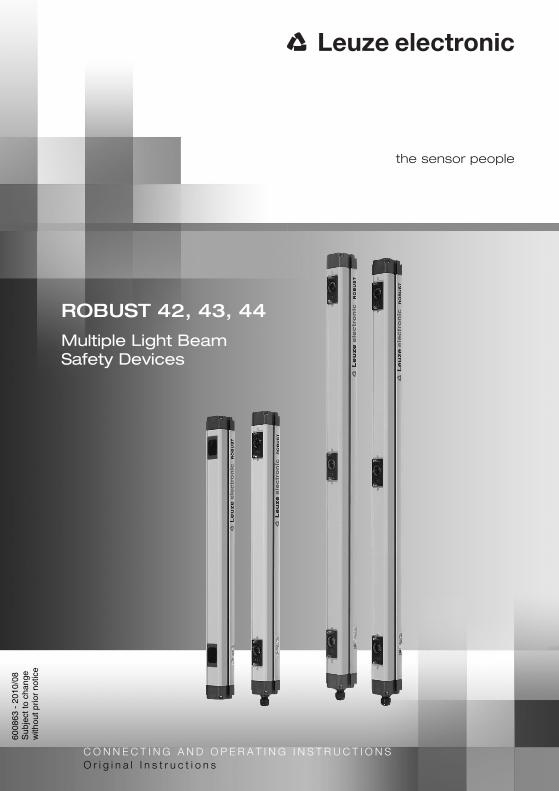
ROBUST 42, 43, 44
Multiple Light Beam Safety Devices
6008
63 -
201
0/08
Sub
ject
to c
hang
ew
ithou
t prio
r no
tice
C O N N E C T I N G A N D O P E R A T I N G I N S T R U C T I O N SO r i g i n a l I n s t r u c t i o n s
2 ROBUST 42, 43, 44 Leuze electronic
DE
UT
SC
HE
NG
LIS
HF
RA
NÇ
AIS
ITA
LIA
NO
ES
PA
ÑO
LN
ED
ER
LA
ND
S
Notes on using these connecting and operating instructions
Warning!These instructions contain information on the efficiency in the use of ROBUST multiple light beam safety devices. These instructions constitute a part of the scope of delivery.
Warning and safety notes are indicated by the symbol
The Leuze electronic GmbH + Co. KG is not liable for damage resulting from improper use. Acquaintance with these instructions constitutes part of the knowledge required for proper use.© Reprint and reproduction, in whole or in part, only with the explicit permission from:Leuze electronic GmbH + Co. KG In der Braike 1 D-73277 Owen - Teck / Germany Phone +49 (0) 7021 / 573-0 Fax +49 (0) 7021 / 573-199 [email protected] www.leuze.com
Contents
Leuze electronic ROBUST 42, 43, 44 3
TN
T 3
5/7-
24V
DE
UT
SC
HE
NG
LIS
HF
RA
NÇ
AIS
ITA
LIA
NO
ES
PA
ÑO
LN
ED
ER
LA
ND
S
1 System Overview and Possibilities of Use ...................................................................... 6
1.1 General ................................................................................................................................ 6
1.2 Approvals ............................................................................................................................. 61.3 Overview of Product Features........................................................................................................7
1.4 Alternative Devices and Possibilities of Use ........................................................................ 7
2 Safety .................................................................................................................................. 8
2.1 Approved purpose and foreseeable improper operation...................................................... 82.1.1 Proper use............................................................................................................................82.1.2 Foreseeable misuse............................................................................................................. 9
2.2 Competent personnel......................................................................................................... 10
2.3 Responsibility for safety .....................................................................................................10
2.4 Exemption of liability .......................................................................................................... 10
3 Structure and Function.................................................................................................... 11
3.1 System Overview ............................................................................................................... 11
3.2 Mode of Operation ............................................................................................................. 12
4 Displays ............................................................................................................................ 13
4.1 Function, Warning and Malfunction Messages .................................................................. 13
5 Installation ........................................................................................................................14
5.1 General Installation Specifications ..................................................................................... 14
5.2 Safety Distance .................................................................................................................. 145.2.1 Distance to Reflecting Surfaces ......................................................................................... 15
5.3 Installation Specifications for ROBUST multiple light beam safety devices for Vertical Access Control .................................................................................................16
5.4 Mechanical installation .................................................................................................................17
5.5 Adjustment / Start-Up......................................................................................................... 18
6 Electrical Installation ....................................................................................................... 19
6.1 Installation Specifications...................................................................................................19
6.2 Connection Technique ....................................................................................................... 19
6.3 Connection Examples ........................................................................................................ 21
6.4 Power Supply ..................................................................................................................... 24
7 Testing .............................................................................................................................. 25
7.1 Before the initial start-up and following modifications ........................................................ 257.1.1 Checklist – before the initial start-up .................................................................................. 26
7.2 To be performed periodically by competent personnel ...................................................... 27
7.3 To be performed daily by the operating personnel............................................................. 277.3.1 Check list – daily or at change of shift................................................................................28
Contents
4 ROBUST 42, 43, 44 Leuze electronic
DE
UT
SC
HE
NG
LIS
HF
RA
NÇ
AIS
ITA
LIA
NO
ES
PA
ÑO
LN
ED
ER
LA
ND
S
8 Technical Data and Dimensional Drawings................................................................... 29
8.1 Selection and Notes on Ordering Accessories .................................................................. 34
Contents
Leuze electronic ROBUST 42, 43, 44 5
TN
T 3
5/7-
24V
DE
UT
SC
HE
NG
LIS
HF
RA
NÇ
AIS
ITA
LIA
NO
ES
PA
ÑO
LN
ED
ER
LA
ND
S
System Overview and Possibilities of Use
6 ROBUST 42, 43, 44 Leuze electronic
DE
UT
SC
HE
NG
LIS
HF
RA
NÇ
AIS
ITA
LIA
NO
ES
PA
ÑO
LN
ED
ER
LA
ND
S
1 System Overview and Possibilities of Use
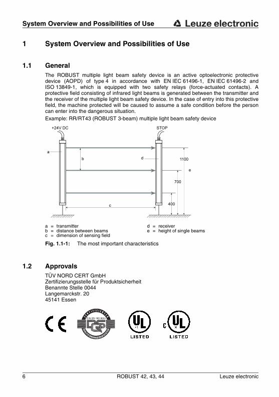
1.1 GeneralThe ROBUST multiple light beam safety device is an active optoelectronic protective device (AOPD) of type 4 in accordance with EN IEC 61496-1, EN IEC 61496-2 and ISO 13849-1, which is equipped with two safety relays (force-actuated contacts). A protective field consisting of infrared light beams is generated between the transmitter and the receiver of the multiple light beam safety device. In the case of entry into this protective field, the machine protected will be caused to assume a safe condition before the person can enter into the dangerous situation.Example: RR/RT43 (ROBUST 3-beam) multiple light beam safety device
1.2 Approvals
a = transmitterb = distance between beamsc = dimension of sensing field
d = receivere = height of single beams
Fig. 1.1-1: The most important characteristics
TÜV NORD CERT GmbHZertifizierungsstelle für ProduktsicherheitBenannte Stelle 0044Langemarckstr. 2045141 Essen
System Overview and Possibilities of Use
Leuze electronic ROBUST 42, 43, 44 7
TN
T 3
5/7-
24V
DE
UT
SC
HE
NG
LIS
HF
RA
NÇ
AIS
ITA
LIA
NO
ES
PA
ÑO
LN
ED
ER
LA
ND
S
1.3 Overview of Product Features• Switching outputs with positively driven safety relay contacts• Simple connection with uncomplicated terminal device• Plug accessories according to DIN 43651• Glass optical parts with fixing bolt for the fitting of a laser alignment aid• Integrated lens heating system for use in extreme environmental conditions• Compact aluminium extrusion profiles with adjustable M6 T-slot nuts• Reliable connection into the controller with Safety Interface Modules of
MSI Series.
1.4 Alternative Devices and Possibilities of UseThe ROBUST is available in different model series. All model series have something in common: The same technology!The RRT42 is a two-beam multiple light beam safety device with an optical spacing of 500 mm and an integrated transmitter and receiver mirrow (AMI 42), it forms a functional unit. (Dimensional sketches PM2-500 and AMI 42, see Chapter 7).RR43 receiver and RT43 transmitter are a functional unit with separate transmitter and receiver profile. 3-beam system with an optical distance of 400 mm.The RRT44 is a 4-beam multiple light beam safety device. The transmitter and receiver systems are located in a profile with an optical spacing of 300 mm and can function only with the PM4-300 passive reversing mirror.
Safety
8 ROBUST 42, 43, 44 Leuze electronic
DE
UT
SC
HE
NG
LIS
HF
RA
NÇ
AIS
ITA
LIA
NO
ES
PA
ÑO
LN
ED
ER
LA
ND
S
2 SafetyBefore using the safety sensor, a risk evaluation must be performed according to valid standards (e.g. EN ISO 14121, EN ISO 12100-1, ISO 13849-1, IEC 61508, EN 62061). The result of the risk assessment determines the required safety level of the safety sensor (see Table 2.1-1). For mounting, operating and testing, document "ROBUST 42, 43, 44 Multiple Light Beam Safety Devices" as well as all applicable national and international standards, regulations, rules and directives must be observed. Relevant and supplied documents must be observed, printed out and handed to the affected personnel.Before working with the safety sensor, completely read and understand the documents applicable to your task.In particular, the following national and international legal regulations apply for the start-up, technical inspections and work with safety sensors:• Machinery directive 2006/42/EC• Low voltage directive 2006/95/EC• Electromagnetic compatibility directive 2004/108/EC• Use of Work Equipment Directive 89/655/EEC supplemented by Directive 95/63 EC• OSHA 1910 Subpart 0• Safety regulations• Accident-prevention regulations and safety rules• Ordinance on Industrial Safety and Health and Labor Protection Act• Device Safety Act
Notice!For safety-related information you may also contact the local authorities (e.g., industrial inspectorate, employer's liability insurance association, labor inspectorate, occupational safety and health authority).
2.1 Approved purpose and foreseeable improper operation
Warning!A running machine can cause severe injuries! Make certain that, during all conversions, maintenance work and inspections, the system is securely shut down and protected against being restarted again.
2.1.1 Proper use
• The safety sensor must only be used after it has been selected in accordance with the respectively applicable instructions and relevant standards, rules and regulations regard-ing labor protection and occupational safety, and after it has been installed on the machine, connected, commissioned, and checked by a competent person.
• When selecting the safety sensor it must be ensured that its safety-related capability meets or exceeds the required performance level PLr ascertained in the risk assess-ment.
Safety
Leuze electronic ROBUST 42, 43, 44 9
TN
T 3
5/7-
24V
DE
UT
SC
HE
NG
LIS
HF
RA
NÇ
AIS
ITA
LIA
NO
ES
PA
ÑO
LN
ED
ER
LA
ND
S
The following table shows the safety-related characteristic parameters of the ROBUST 42, 43, 44 series.
Table 2.1-1: Safety-related characteristic parameters of the ROBUST 42, 43, 44 series
• The safety sensor protects persons at access points or at points of operation of machines and plants.
• The safety sensor only detects persons upon entry to the danger zone; it does not detect persons who are located within the danger zone. For this reason, a start/restart interlock is mandatory.
• The construction of the safety sensor must not be altered. When manipulating the safety sensor, the protective function is no longer guaranteed. Manipulating the safety sensor also voids all warranty claims against the manufacturer of the safety sensor.
• The safety sensor must be tested regularly by competent personnel.• The safety sensor must be exchanged after a maximum of 20 years. Repairs or the
exchange of parts subject to wear and tear do not extend the service life.
2.1.2 Foreseeable misuse
In principle, the safety sensor is not suitable as a protective device in case of:• danger of objects being expelled or hot or dangerous liquids spurting from the danger
zone• applications in explosive or easily flammable atmospheres• reachability of the points of operation by hand from the mounting location of the safety
sensor• detection of the presence of persons in danger areas
Type in accordance with IEC/EN 61496 Type 4
Performance Level (PL) in accordance with ISO 13849-1: 2008
PL e
Category in accordance with ISO 13849-1
Cat. 4
Mean probability of a dangerous failure per hour (PFHd) as a function of the mean number of annual switching cy-cles of the relay nop*
nop = 4,800: 3.7 x 10⁻⁸ 1/h
nop = 28,800: 5.2 x 10⁻⁸ 1/h
nop = 86,400: 1.0 x 10⁻⁷ 1/h
*nop = mean number of annual actuations, see C.4.2 and C.4.3 of ISO 13849-1: 2008
Use the following formula to calculate the mean number of annual actuations:
In doing so, make the following assumptions with regard to the use of the component:hop = mean operating time in hours per daydop = mean operating time in days per yeartcycle = mean time between the start of two successive cycles of the component (e.g switching of a
valve) in seconds per cycle
nop dop hop 3600s/h⋅ ⋅( ) tZyklus÷=
Safety
10 ROBUST 42, 43, 44 Leuze electronic
DE
UT
SC
HE
NG
LIS
HF
RA
NÇ
AIS
ITA
LIA
NO
ES
PA
ÑO
LN
ED
ER
LA
ND
S
2.2 Competent personnelPrerequisites for competent personnel:• he has a suitable technical education• he knows the rules and regulations for occupational safety, safety at work and safety
technology and can assess the safety of the machine• he knows the instructions for the safety sensor and the machine• he has been instructed by the responsible person on the mounting and operation of the
machine and of the safety sensor
2.3 Responsibility for safetyManufacturer and operating company must ensure that the machine and implemented safety sensor function properly and that all affected persons are adequately informed and trained.The type and content of all imparted information must not lead to unsafe actions by users.
The manufacturer of the machine is responsible for:• safe machine construction• safe implementation of the safety sensor• imparting all relevant information to the operating company• adhering to all regulations and directives for the safe starting-up of the machine
The company operating the machine is responsible for:• instructing the operating personnel• maintaining the safe operation of the machine• adhering to all regulations and directives for occupational safety and safety at work• regular testing by competent personnel
2.4 Exemption of liabilityLeuze electronic GmbH + Co. KG is not liable in the following cases:• safety sensor is not used as intended• safety notices are not adhered to• reasonably foreseeable misuse is not taken into account• mounting and electrical connection are not properly performed• proper function is not tested• changes (e.g., constructional) are made to the safety sensor
Structure and Function
Leuze electronic ROBUST 42, 43, 44 11
TN
T 3
5/7-
24V
DE
UT
SC
HE
NG
LIS
HF
RA
NÇ
AIS
ITA
LIA
NO
ES
PA
ÑO
LN
ED
ER
LA
ND
S
3 Structure and Function
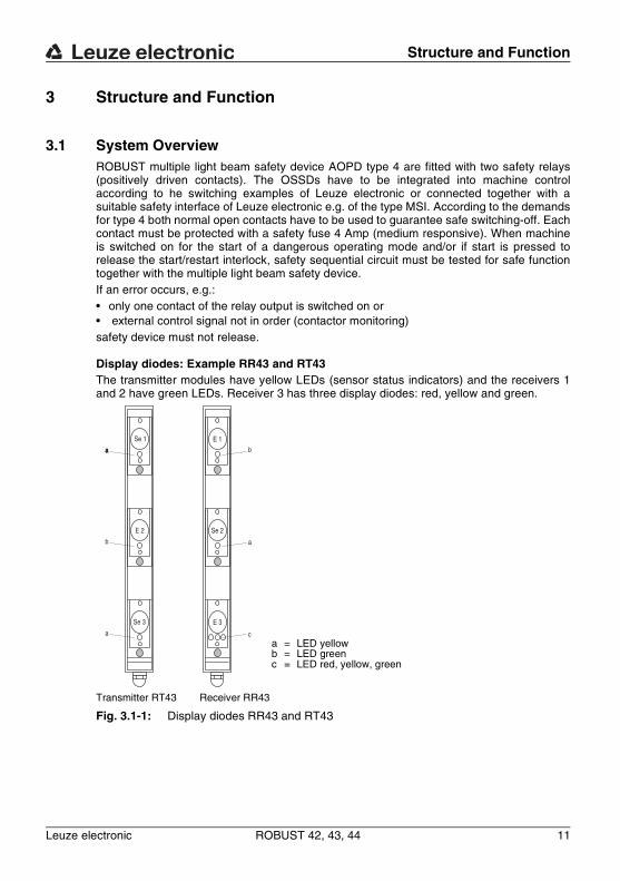
3.1 System OverviewROBUST multiple light beam safety device AOPD type 4 are fitted with two safety relays (positively driven contacts). The OSSDs have to be integrated into machine control according to he switching examples of Leuze electronic or connected together with a suitable safety interface of Leuze electronic e.g. of the type MSI. According to the demands for type 4 both normal open contacts have to be used to guarantee safe switching-off. Each contact must be protected with a safety fuse 4 Amp (medium responsive). When machine is switched on for the start of a dangerous operating mode and/or if start is pressed to release the start/restart interlock, safety sequential circuit must be tested for safe function together with the multiple light beam safety device.If an error occurs, e.g.:• only one contact of the relay output is switched on or• external control signal not in order (contactor monitoring)safety device must not release.
Display diodes: Example RR43 and RT43The transmitter modules have yellow LEDs (sensor status indicators) and the receivers 1 and 2 have green LEDs. Receiver 3 has three display diodes: red, yellow and green.
Transmitter RT43 Receiver RR43
Fig. 3.1-1: Display diodes RR43 and RT43
Se 1
E 2
E 1
E 3Se 3
Se 2
a
b
a
aa b
a
ca = LED yellowb = LED greenc = LED red, yellow, green
Structure and Function
12 ROBUST 42, 43, 44 Leuze electronic
DE
UT
SC
HE
NG
LIS
HF
RA
NÇ
AIS
ITA
LIA
NO
ES
PA
ÑO
LN
ED
ER
LA
ND
S
3.2 Mode of OperationThe ROBUST works in the "Protection Operation Without Restart Interlock" mode of operation. When all light axes are received, the OSSD outputs of the receiver switch on. With the interruption of at least one light axis, the contacts open within the system reaction time. As soon as all light axes are free again, the OSSDs switch back on again automatically. Additional functions, such as restart interlock, contactor monitoring or muting can be implemented through the safety interfaces of MSI Series.
Displays
Leuze electronic ROBUST 42, 43, 44 13
TN
T 3
5/7-
24V
DE
UT
SC
HE
NG
LIS
HF
RA
NÇ
AIS
ITA
LIA
NO
ES
PA
ÑO
LN
ED
ER
LA
ND
S
4 Displays
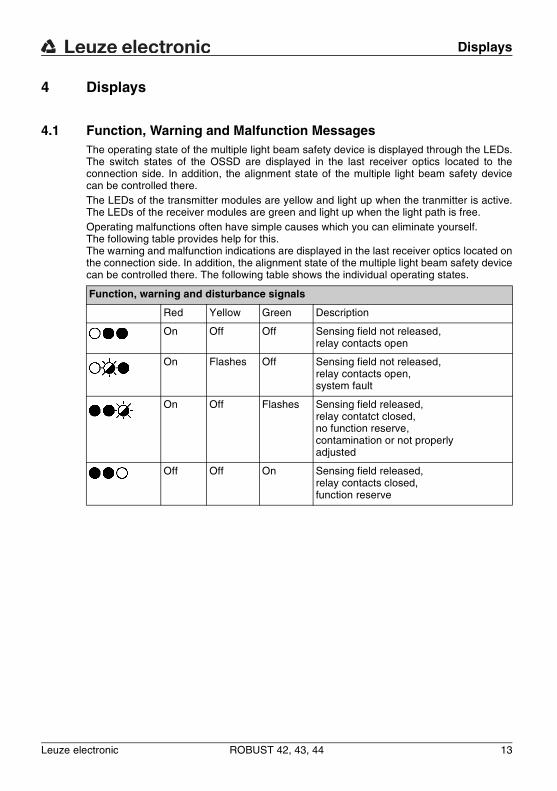
4.1 Function, Warning and Malfunction MessagesThe operating state of the multiple light beam safety device is displayed through the LEDs. The switch states of the OSSD are displayed in the last receiver optics located to the connection side. In addition, the alignment state of the multiple light beam safety device can be controlled there.The LEDs of the transmitter modules are yellow and light up when the tranmitter is active. The LEDs of the receiver modules are green and light up when the light path is free.Operating malfunctions often have simple causes which you can eliminate yourself. The following table provides help for this. The warning and malfunction indications are displayed in the last receiver optics located on the connection side. In addition, the alignment state of the multiple light beam safety device can be controlled there. The following table shows the individual operating states.
Function, warning and disturbance signals
Red Yellow Green Description
On Off Off Sensing field not released, relay contacts open
On Flashes Off Sensing field not released, relay contacts open, system fault
On Off Flashes Sensing field released, relay contatct closed, no function reserve, contamination or not properly adjusted
Off Off On Sensing field released, relay contacts closed, function reserve
Installation
14 ROBUST 42, 43, 44 Leuze electronic
DE
UT
SC
HE
NG
LIS
HF
RA
NÇ
AIS
ITA
LIA
NO
ES
PA
ÑO
LN
ED
ER
LA
ND
S
5 Installation
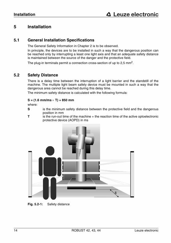
5.1 General Installation SpecificationsThe General Safety Information in Chapter 2 is to be observed.In principle, the devices are to be installed in such a way that the dangerous position can be reached only by interrupting a least one light axis and that an adequate safety distance is maintained between the source of the danger and the protective field.
The plug-in terminals permit a connection cross-section of up to 2,5 mm2.
5.2 Safety DistanceThere is a delay time between the interruption of a light barrier and the standstill of the machine. The multiple light beam safety device must be mounted in such a way that the dangerous area cannot be reached during this delay time.The minimum safety distance is calculated with the following formula:
S = (1.6 mm/ms × T) + 850 mmwhere:S is the minimum safety distance between the protective field and the dangerous
position in mmT is the run-out time of the machine + the reaction time of the active optoelectronic
protective device (AOPD) in ms
Fig. 5.2-1: Safety distance
S
Installation
Leuze electronic ROBUST 42, 43, 44 15
TN
T 3
5/7-
24V
DE
UT
SC
HE
NG
LIS
HF
RA
NÇ
AIS
ITA
LIA
NO
ES
PA
ÑO
LN
ED
ER
LA
ND
S
5.2.1 Distance to Reflecting Surfaces
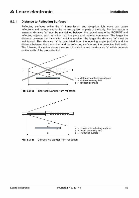
Reflecting surfaces within the 4° transmission and reception light cone can cause reflections and thereby lead to the non-recognition of parts of the body. For this reason, a minimum distance "a" must be maintained between the optical axes of he ROBUST and reflecting objects, such as shiny machine parts and material containers. The larger the distance between the transmitter and the receiver, the larger the distance "a" must be maintained. This distance "a" is calculated from the opening angle (+/-2.0°) and the distance between the transmitter and the reflecting surface and the protective field width. The following illustration shows the correct installation and the distance "a" which depends on the width of the protective field.
Fig. 5.2-2: Incorrect: Danger from reflection
Fig. 5.2-3: Correct: No danger from reflection
a = distance to reflecting surfacesb = width of sensing fieldc = reflecting surface
a = distance to reflecting surfacesb = width of sensing fieldc = reflecting surface
Installation
16 ROBUST 42, 43, 44 Leuze electronic
DE
UT
SC
HE
NG
LIS
HF
RA
NÇ
AIS
ITA
LIA
NO
ES
PA
ÑO
LN
ED
ER
LA
ND
S
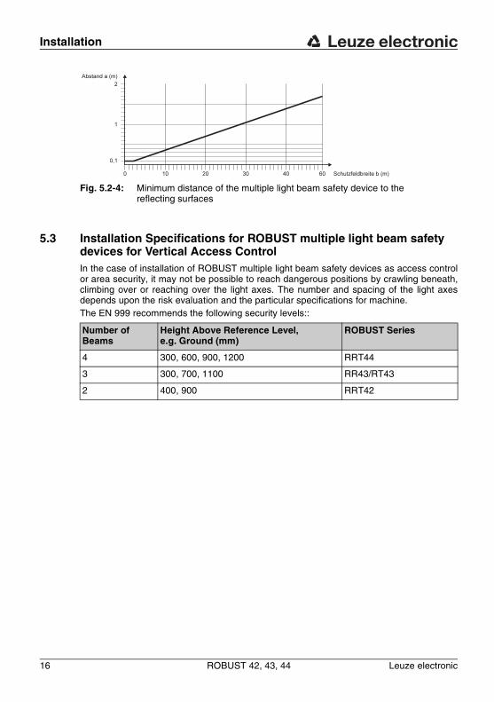
5.3 Installation Specifications for ROBUST multiple light beam safety devices for Vertical Access ControlIn the case of installation of ROBUST multiple light beam safety devices as access control or area security, it may not be possible to reach dangerous positions by crawling beneath, climbing over or reaching over the light axes. The number and spacing of the light axes depends upon the risk evaluation and the particular specifications for machine.The EN 999 recommends the following security levels::
Fig. 5.2-4: Minimum distance of the multiple light beam safety device to the reflecting surfaces
Number of Beams
Height Above Reference Level, e.g. Ground (mm)
ROBUST Series
4 300, 600, 900, 1200 RRT44
3 300, 700, 1100 RR43/RT43
2 400, 900 RRT42
Installation
Leuze electronic ROBUST 42, 43, 44 17
TN
T 3
5/7-
24V
DE
UT
SC
HE
NG
LIS
HF
RA
NÇ
AIS
ITA
LIA
NO
ES
PA
ÑO
LN
ED
ER
LA
ND
S
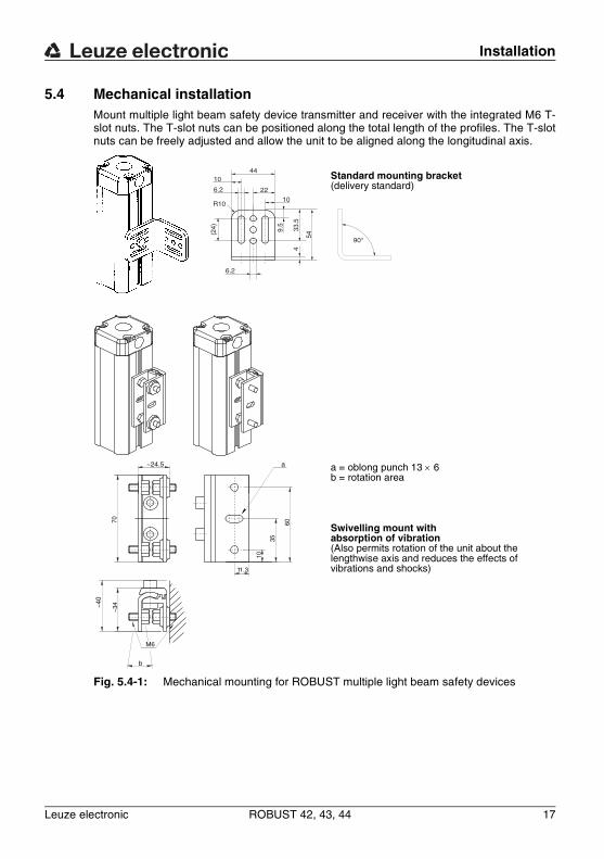
5.4 Mechanical installationMount multiple light beam safety device transmitter and receiver with the integrated M6 T-slot nuts. The T-slot nuts can be positioned along the total length of the profiles. The T-slot nuts can be freely adjusted and allow the unit to be aligned along the longitudinal axis.
Fig. 5.4-1: Mechanical mounting for ROBUST multiple light beam safety devices
R10
10
22
44
10
33.5
4
54
90°
9.5
(24)
6.2
6.2
b
M6
70
~24.5
11.3
a
10
35
60
~40
~34
Standard mounting bracket (delivery standard)
a = oblong punch 13 × 6 b = rotation area
Swivelling mount with absorption of vibration (Also permits rotation of the unit about the lengthwise axis and reduces the effects of vibrations and shocks)
Installation
18 ROBUST 42, 43, 44 Leuze electronic
DE
UT
SC
HE
NG
LIS
HF
RA
NÇ
AIS
ITA
LIA
NO
ES
PA
ÑO
LN
ED
ER
LA
ND
S
When mounting the multiple light beam safety device make sure to select fixing screws of the proper length. T-slot nuts can be screwed in up to a depth of 5 mm. Leuze electronic will supply you with a complete swivelling mounting system on request.
5.5 Adjustment / Start-UpBefore switching the multiple light beam safety device on, check the electrical connections. If the LEDs of the transmitter light up yellow, the system is active.Check the orientation of the receiver strip.You can find an overview of the displays of the LEDs in Chapter 4.Optimise the orientation by loosening the attachment and determining the optical centre point by swivelling horizontally and vertically.
Electrical Installation
Leuze electronic ROBUST 42, 43, 44 19
TN
T 3
5/7-
24V
DE
UT
SC
HE
NG
LIS
HF
RA
NÇ
AIS
ITA
LIA
NO
ES
PA
ÑO
LN
ED
ER
LA
ND
S
6 Electrical Installation
6.1 Installation SpecificationsThe General Safety Information in Chapter 2 is to be observed. The electrical installation is to be performed by trained technical personnel. The OSSD outputs of the ROBUST are to e connected to the safety-related part of the machine controller in two channels.The electrical connection can be performed either on the screw terminals in the housing of the transmitter and receiver strip or with a plug connection in compliance with DIN 43651 (accessory). Prepare the connection lines as described in Figure 8.
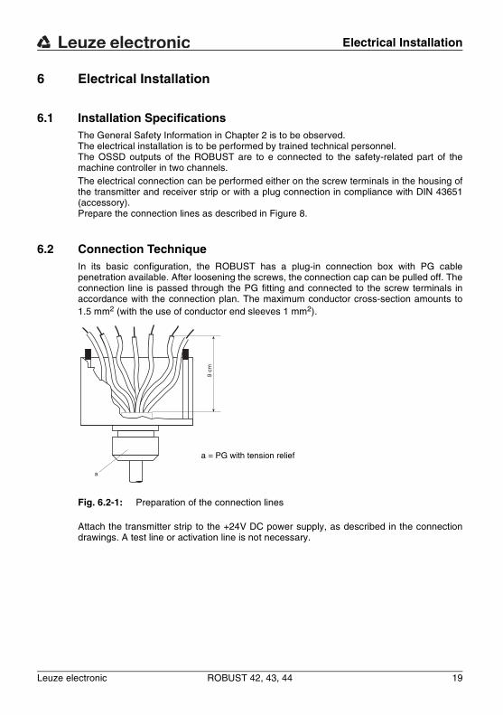
6.2 Connection TechniqueIn its basic configuration, the ROBUST has a plug-in connection box with PG cable penetration available. After loosening the screws, the connection cap can be pulled off. The connection line is passed through the PG fitting and connected to the screw terminals in accordance with the connection plan. The maximum conductor cross-section amounts to 1.5 mm2 (with the use of conductor end sleeves 1 mm2).
Attach the transmitter strip to the +24V DC power supply, as described in the connection drawings. A test line or activation line is not necessary.
Fig. 6.2-1: Preparation of the connection lines
9 cm
a
a = PG with tension relief
Electrical Installation
20 ROBUST 42, 43, 44 Leuze electronic
DE
UT
SC
HE
NG
LIS
HF
RA
NÇ
AIS
ITA
LIA
NO
ES
PA
ÑO
LN
ED
ER
LA
ND
S
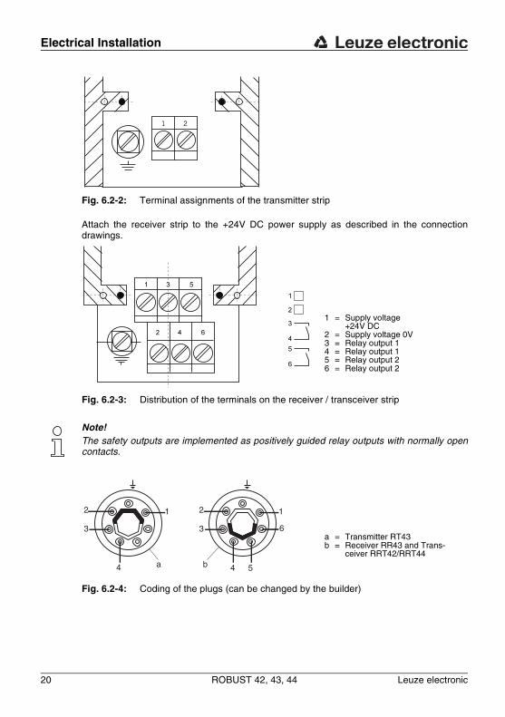
Attach the receiver strip to the +24V DC power supply as described in the connection drawings.
Note!The safety outputs are implemented as positively guided relay outputs with normally open contacts.
Fig. 6.2-2: Terminal assignments of the transmitter strip
Fig. 6.2-3: Distribution of the terminals on the receiver / transceiver strip
Fig. 6.2-4: Coding of the plugs (can be changed by the builder)
1 = Supply voltage +24V DC
2 = Supply voltage 0V3 = Relay output 14 = Relay output 15 = Relay output 26 = Relay output 2
a = Transmitter RT43b = Receiver RR43 and Trans-
ceiver RRT42/RRT44
2
3
1
4
2
3
1
4
6
5a b
Electrical Installation
Leuze electronic ROBUST 42, 43, 44 21
TN
T 3
5/7-
24V
DE
UT
SC
HE
NG
LIS
HF
RA
NÇ
AIS
ITA
LIA
NO
ES
PA
ÑO
LN
ED
ER
LA
ND
S
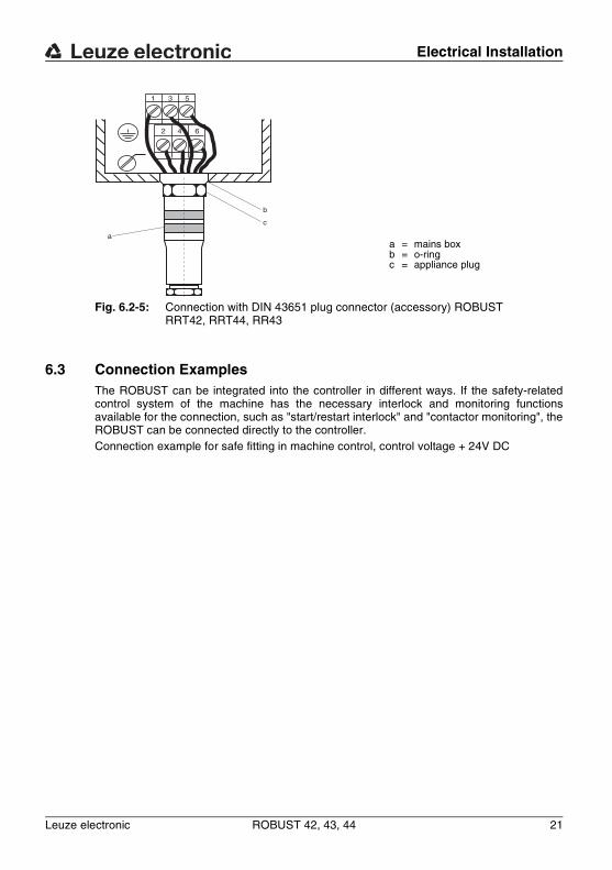
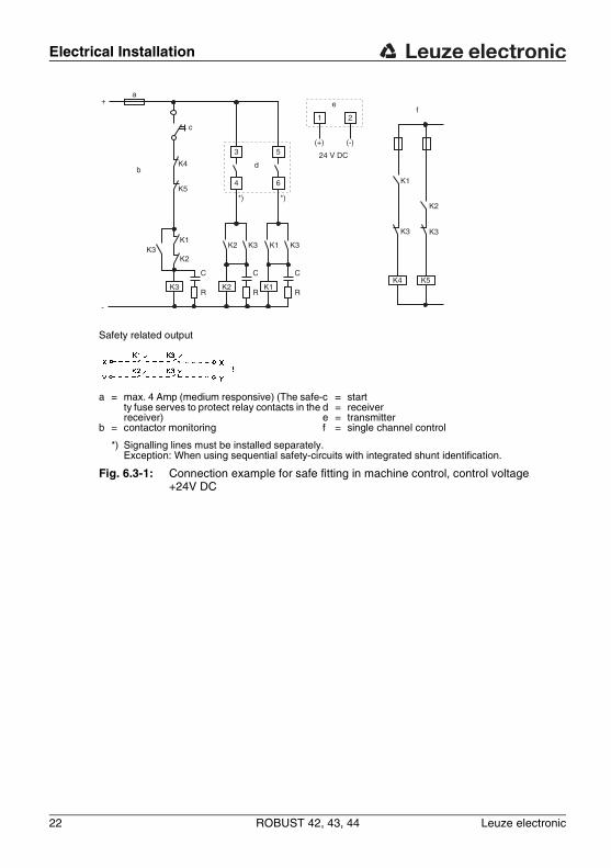
6.3 Connection ExamplesThe ROBUST can be integrated into the controller in different ways. If the safety-related control system of the machine has the necessary interlock and monitoring functions available for the connection, such as "start/restart interlock" and "contactor monitoring", the ROBUST can be connected directly to the controller.Connection example for safe fitting in machine control, control voltage + 24V DC
Fig. 6.2-5: Connection with DIN 43651 plug connector (accessory) ROBUST RRT42, RRT44, RR43
a = mains boxb = o-ringc = appliance plug
1 3 5
2 4 6
a
b
c
Electrical Installation
22 ROBUST 42, 43, 44 Leuze electronic
DE
UT
SC
HE
NG
LIS
HF
RA
NÇ
AIS
ITA
LIA
NO
ES
PA
ÑO
LN
ED
ER
LA
ND
S
Safety related output
a = max. 4 Amp (medium responsive) (The safe-ty fuse serves to protect relay contacts in the receiver)
b = contactor monitoring
c = startd = receivere = transmitterf = single channel control
*) Signalling lines must be installed separately. Exception: When using sequential safety-circuits with integrated shunt identification.
Fig. 6.3-1: Connection example for safe fitting in machine control, control voltage +24V DC
K1
K3
K2
K3
K4 K5
f1 2
(+) (-)
24 V DC
e
K1 K3
C
RK1
K3
C
RK2
K3
C
RK3
K2K1
K2
4
d
3
6
5
*) *)
-
+
b
K5
K4
c
a
Electrical Installation
Leuze electronic ROBUST 42, 43, 44 23
TN
T 3
5/7-
24V
DE
UT
SC
HE
NG
LIS
HF
RA
NÇ
AIS
ITA
LIA
NO
ES
PA
ÑO
LN
ED
ER
LA
ND
S
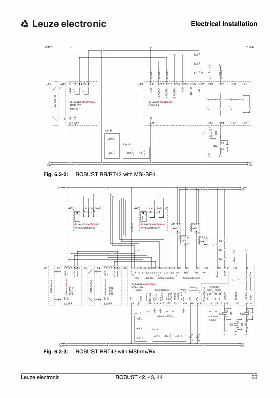
Fig. 6.3-2: ROBUST RR/RT42 with MSI-SR4
Fig. 6.3-3: ROBUST RRT42 with MSI-mx/Rx
Var. B
Var. A
0V+
24V
PE
PM
2-50
0(V
)
ROBUSTRRT42
-K3
-K4
-A1 64
PE
5
2
3-A2
14 24 42
13 23 411
-K4-K3
A1
A2-K3
1
2
1
2
0V
+24V
0VPE
+24V
PE
L+ L+
L- L-
-S1
-K3
-K4
+24
V0V
MSI-SR4
A1-A3
A2
S22 S12 S31 S33 S34 S35
2 A
OP
D-
1 A
OP
D+
33
34
*
A1
A2-K4
*
1
2
2 A
OP
D+
IV-0
RE
S-0
RE
S-I
1
2
1
2
MutingIndicatorsDiagn.
ED
M
Res
et
State Outputs StateWarn.Rx-Output
Wam.
Muting Sensors
OS
SD
2
OS
SD
3
M3 M4
Test
1.2S1 1.1
AOPDs
T2 M1 M2
MSI-mx/Rx
T1
0V+
24V
Safety Switches
2.22.1S4S3S2
S1-
S4
1.1-
1.2
Mu t
ing
Mut
ing
Fai
l ure
MS
I-fa
ult
SS
D
OS
SD
1-M1
+ -
-M2+ -
-M3+ -
-M4+ -
Indication Output
5
A2
A1-K1
1
2
RS
232
1
2
x1
x2
1
2
-K5
-K3
13 14
A2
A1-K2
1
11
33
x1
x2
23231
1027 12630
212026251716
9
-A5 4 24 22
3
15 23 34 35
728 29
A2
A1-K3
18 19 36
-K4
Var. B
-K3
-K4
-K5
Var. A
-K3 -K4 -K5
0V
L+
L+
PE
+24V
0V 0VPE
+24V
L-L-
L-
FE
(vi
a D
IN r
ail)
RO
BU
ST
RR
T42
RO
BU
ST
RR
T42
PE
+24
V
+24
V
0VPE
0V
1-A4 3
2
1-A2 3
2
4 5
FE
4
FE
5-A1 6 6-A3
PM
2-50
0(V
)
PM
2-50
0(V
)
S200-M3C1-M20
21-A7 1211 22
S200-M3C1-M20
21-A6 1211 22
IndicationOutput
Electrical Installation
24 ROBUST 42, 43, 44 Leuze electronic
DE
UT
SC
HE
NG
LIS
HF
RA
NÇ
AIS
ITA
LIA
NO
ES
PA
ÑO
LN
ED
ER
LA
ND
S
6.4 Power SupplyThe transmitter and the receiver are to be supplied with +24V DC ± 15 %. The maximum current consumption of the ROBUST is 280 mA. The power supply must exhibit a reliable network separation in accordance with EN 60204 and bridge short-term network failures of up to 20 ms.
Testing
Leuze electronic ROBUST 42, 43, 44 25
TN
T 3
5/7-
24V
DE
UT
SC
HE
NG
LIS
HF
RA
NÇ
AIS
ITA
LIA
NO
ES
PA
ÑO
LN
ED
ER
LA
ND
S
7 Testing
WarningA running machine can cause severe injuries! Make certain that, during all conversions, maintenance work and inspections, the system is securely shut down and protected against being restarted again.
The safety sensors must be exchanged after a maximum of 20 years.• Always exchange entire safety sensors.• For the tests, observe nationally applicable regulations.• Document all tests in a comprehensible manner.
7.1 Before the initial start-up and following modificationsAcc. to IEC TS62046 and national regulations (e.g. EU directive 89/655 EEC), tests are to be performed by competent personnel in the following situations:• Prior to the initial start-up• Following modifications to the machine• After longer machine downtime• Following retrofitting or reconfiguration of the safety sensor
WarningUnforeseeable behavior of the machine during the initial commissioning can lead to severe injuries! Make certain that there are no persons in the danger zone.
• Test the effectiveness of the shut-down function in all operating modes of the machine acc. to the following checklist.
• Document all tests in a comprehensible manner and include the configuration of the safety sensor along with the data for the safety- and minimum distances in the documentation.
• Before they begin work, train the operating personnel on their respective tasks. The training is the responsibility of the operating company.
• Attach notices regarding daily testing in the respective national language of the operating personnel on the machine in a highly visible location, e.g. by printing out the correspond-ing chapter (see Chapter 7.3).
• Check whether the safety sensor was correctly selected acc. to the locally applicable regulations and directives.
• Check whether the safety sensor is operated acc. to the specified environmental conditions.
• Make certain that the safety sensor is protected against overcurrent.• Perform a visual inspection for damage and test the electrical function.
Testing
26 ROBUST 42, 43, 44 Leuze electronic
DE
UT
SC
HE
NG
LIS
HF
RA
NÇ
AIS
ITA
LIA
NO
ES
PA
ÑO
LN
ED
ER
LA
ND
S
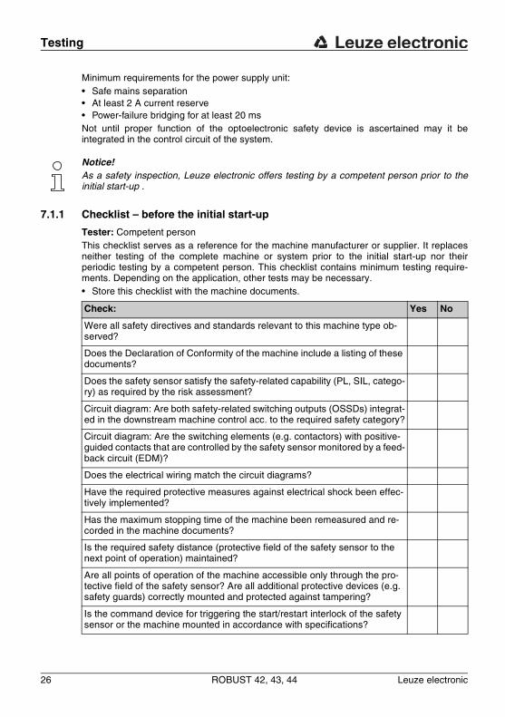
Minimum requirements for the power supply unit:• Safe mains separation• At least 2 A current reserve• Power-failure bridging for at least 20 msNot until proper function of the optoelectronic safety device is ascertained may it be integrated in the control circuit of the system.
Notice!As a safety inspection, Leuze electronic offers testing by a competent person prior to the initial start-up .
7.1.1 Checklist – before the initial start-up
Tester: Competent personThis checklist serves as a reference for the machine manufacturer or supplier. It replaces neither testing of the complete machine or system prior to the initial start-up nor their periodic testing by a competent person. This checklist contains minimum testing require-ments. Depending on the application, other tests may be necessary.• Store this checklist with the machine documents.
Check: Yes No
Were all safety directives and standards relevant to this machine type ob-served?
Does the Declaration of Conformity of the machine include a listing of these documents?
Does the safety sensor satisfy the safety-related capability (PL, SIL, catego-ry) as required by the risk assessment?
Circuit diagram: Are both safety-related switching outputs (OSSDs) integrat-ed in the downstream machine control acc. to the required safety category?
Circuit diagram: Are the switching elements (e.g. contactors) with positive-guided contacts that are controlled by the safety sensor monitored by a feed-back circuit (EDM)?
Does the electrical wiring match the circuit diagrams?
Have the required protective measures against electrical shock been effec-tively implemented?
Has the maximum stopping time of the machine been remeasured and re-corded in the machine documents?
Is the required safety distance (protective field of the safety sensor to the next point of operation) maintained?
Are all points of operation of the machine accessible only through the pro-tective field of the safety sensor? Are all additional protective devices (e.g. safety guards) correctly mounted and protected against tampering?
Is the command device for triggering the start/restart interlock of the safety sensor or the machine mounted in accordance with specifications?
Testing
Leuze electronic ROBUST 42, 43, 44 27
TN
T 3
5/7-
24V
DE
UT
SC
HE
NG
LIS
HF
RA
NÇ
AIS
ITA
LIA
NO
ES
PA
ÑO
LN
ED
ER
LA
ND
S
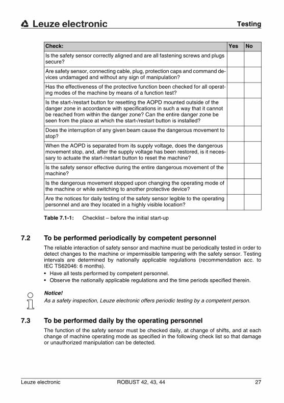
Table 7.1-1: Checklist – before the initial start-up
7.2 To be performed periodically by competent personnelThe reliable interaction of safety sensor and machine must be periodically tested in order to detect changes to the machine or impermissible tampering with the safety sensor. Testing intervals are determined by nationally applicable regulations (recommendation acc. to IEC TS62046: 6 months).• Have all tests performed by competent personnel.• Observe the nationally applicable regulations and the time periods specified therein.
Notice!As a safety inspection, Leuze electronic offers periodic testing by a competent person.
7.3 To be performed daily by the operating personnelThe function of the safety sensor must be checked daily, at change of shifts, and at each change of machine operating mode as specified in the following check list so that damage or unauthorized manipulation can be detected.
Is the safety sensor correctly aligned and are all fastening screws and plugs secure?
Are safety sensor, connecting cable, plug, protection caps and command de-vices undamaged and without any sign of manipulation?
Has the effectiveness of the protective function been checked for all operat-ing modes of the machine by means of a function test?
Is the start-/restart button for resetting the AOPD mounted outside of the danger zone in accordance with specifications in such a way that it cannot be reached from within the danger zone? Can the entire danger zone be seen from the place at which the start-/restart button is installed?
Does the interruption of any given beam cause the dangerous movement to stop?
When the AOPD is separated from its supply voltage, does the dangerous movement stop, and, after the supply voltage has been restored, is it neces-sary to actuate the start-/restart button to reset the machine?
Is the safety sensor effective during the entire dangerous movement of the machine?
Is the dangerous movement stopped upon changing the operating mode of the machine or while switching to another protective device?
Are the notices for daily testing of the safety sensor legible to the operating personnel and are they located in a highly visible location?
Check: Yes No
Testing
28 ROBUST 42, 43, 44 Leuze electronic
DE
UT
SC
HE
NG
LIS
HF
RA
NÇ
AIS
ITA
LIA
NO
ES
PA
ÑO
LN
ED
ER
LA
ND
S
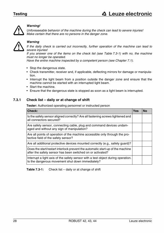
Warning!Unforeseeable behavior of the machine during the check can lead to severe injuries! Make certain that there are no persons in the danger zone.
WarningIf the daily check is carried out incorrectly, further operation of the machine can lead to severe injuries! If you answer one of the items on the check list (see Table 7.3-1) with no, the machine must no longer be operated. Have the entire machine inspected by a competent person (see Chapter 7.1).
• Stop the dangerous state.• Check transmitter, receiver and, if applicable, deflecting mirrors for damage or manipula-
tion.• Interrupt the light beam from a position outside the danger zone and ensure that the
machine cannot be started with an interrupted light beam.• Start the machine.• Ensure that the dangerous state is stopped as soon as a light beam is interrupted.
7.3.1 Check list – daily or at change of shift
Tester: Authorized operating personnel or instructed person
Table 7.3-1: Check list – daily or at change of shift
Check: Yes No
Is the safety sensor aligned correctly? Are all fastening screws tightened and all connectors secured?
Are safety sensor, connecting cable, plug and command devices undam-aged and without any sign of manipulation?
Are all points of operation of the machine accessible only through the pro-tective field of the safety sensor?
Are all additional protective devices mounted correctly (e.g., safety guard)?
Does the start/restart interlock prevent the automatic start-up of the machine after the safety sensor has been switched on or activated?
Interrupt a light axis of the safety sensor with a test object during operation.Is the dangerous movement shut down immediately?
Technical Data and Dimensional Drawings
Leuze electronic ROBUST 42, 43, 44 29
TN
T 3
5/7-
24V
DE
UT
SC
HE
NG
LIS
HF
RA
NÇ
AIS
ITA
LIA
NO
ES
PA
ÑO
LN
ED
ER
LA
ND
S
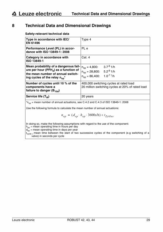
8 Technical Data and Dimensional Drawings
Safety-relevant technical data
Type in accordance with IEC/EN 61496
Type 4
Performance Level (PL) in accor-dance with ISO 13849-1: 2008
PL e
Category in accordance with ISO 13849-1
Cat. 4
Mean probability of a dangerous fail-ure per hour (PFHd) as a function of the mean number of annual switch-ing cycles of the relay nop*
nop = 4,800: 3.7-8 1/h
nop = 28,800: 5.2-8 1/h
nop = 86,400: 1.0-7 1/h
Number of cycles until 10 % of the components have afailure to danger (B10d)
400,000 switching cycles at rated load20 million switching cycles at 20% of rated load
Service life (TM) 20 years
*nop = mean number of annual actuations, see C.4.2 and C.4.3 of ISO 13849-1: 2008
Use the following formula to calculate the mean number of annual actuations:
In doing so, make the following assumptions with regard to the use of the component:hop = mean operating time in hours per daydop = mean operating time in days per yeartcycle = mean time between the start of two successive cycles of the component (e.g switching of a
valve) in seconds per cycle
nop dop hop 3600s/h⋅ ⋅( ) tZyklus÷=
Technical Data and Dimensional Drawings
30 ROBUST 42, 43, 44 Leuze electronic
DE
UT
SC
HE
NG
LIS
HF
RA
NÇ
AIS
ITA
LIA
NO
ES
PA
ÑO
LN
ED
ER
LA
ND
S
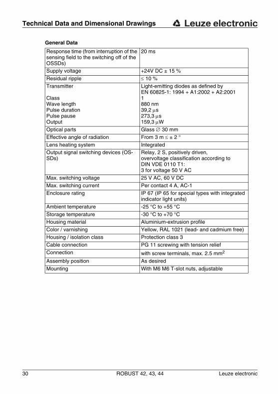
General Data
Response time (from interruption of the sensing field to the switching off of the OSSDs)
20 ms
Supply voltage +24V DC ± 15 %
Residual ripple ≤ 10 %
Transmitter
ClassWave lengthPulse durationPulse pauseOutput
Light-emitting diodes as defined by EN 60825-1: 1994 + A1:2002 + A2:20011880 nm39,2 μs273,3 μs159,3 μW
Optical parts Glass ∅ 30 mm
Effective angle of radiation From 3 m ≤ ± 2 °
Lens heating system IntegratedOutput signal switching devices (OS-SDs)
Relay, 2 S, positively driven, overvoltage classification according to DIN VDE 0110 T1: 3 for voltage 50 V AC
Max. switching voltage 25 V AC, 60 V DC
Max. switching current Per contact 4 A, AC-1
Enclosure rating IP 67 (IP 65 for special types with integrated indicator light units)
Ambient temperature -25 °C to +55 °C
Storage temperature -30 °C to +70 °CHousing material Aluminium-extrusion profile
Color / varnishing Yellow, RAL 1021 (lead- and cadmium free)
Housing / isolation class Protection class 3
Cable connection PG 11 screwing with tension relief
Connection with screw terminals, max. 2.5 mm2
Assembly position As desired
Mounting With M6 M6 T-slot nuts, adjustable
Technical Data and Dimensional Drawings
Leuze electronic ROBUST 42, 43, 44 31
TN
T 3
5/7-
24V
DE
UT
SC
HE
NG
LIS
HF
RA
NÇ
AIS
ITA
LIA
NO
ES
PA
ÑO
LN
ED
ER
LA
ND
S
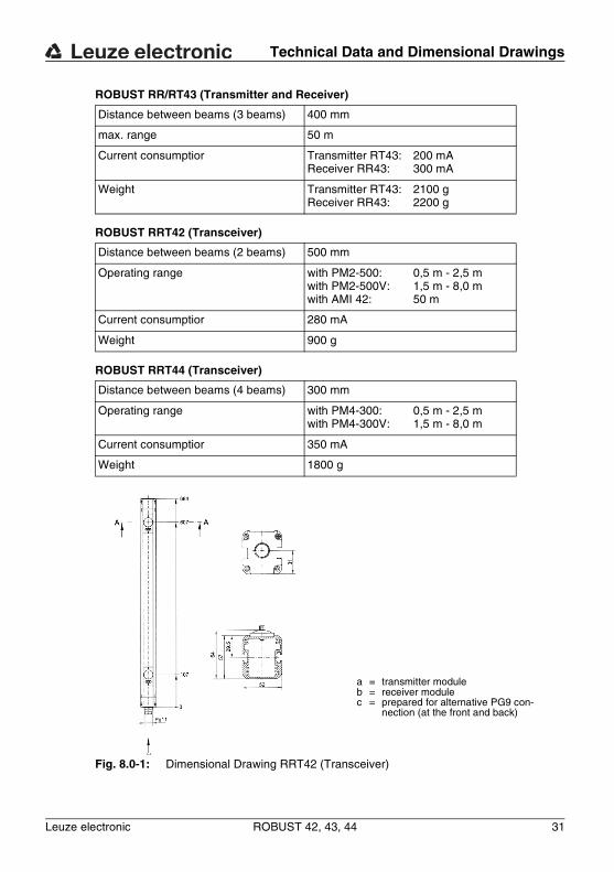
ROBUST RR/RT43 (Transmitter and Receiver)
ROBUST RRT42 (Transceiver)
ROBUST RRT44 (Transceiver)
Distance between beams (3 beams) 400 mm
max. range 50 m
Current consumptior Transmitter RT43:Receiver RR43:
200 mA300 mA
Weight Transmitter RT43:Receiver RR43:
2100 g2200 g
Distance between beams (2 beams) 500 mm
Operating range with PM2-500: with PM2-500V: with AMI 42:
0,5 m - 2,5 m1,5 m - 8,0 m50 m
Current consumptior 280 mA
Weight 900 g
Distance between beams (4 beams) 300 mm
Operating range with PM4-300:with PM4-300V:
0,5 m - 2,5 m1,5 m - 8,0 m
Current consumptior 350 mA
Weight 1800 g
Fig. 8.0-1: Dimensional Drawing RRT42 (Transceiver)
a = transmitter moduleb = receiver modulec = prepared for alternative PG9 con-
nection (at the front and back)
Technical Data and Dimensional Drawings
32 ROBUST 42, 43, 44 Leuze electronic
DE
UT
SC
HE
NG
LIS
HF
RA
NÇ
AIS
ITA
LIA
NO
ES
PA
ÑO
LN
ED
ER
LA
ND
S
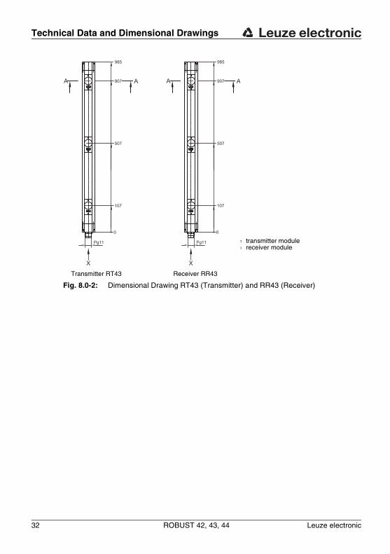
Transmitter RT43 Receiver RR43
Fig. 8.0-2: Dimensional Drawing RT43 (Transmitter) and RR43 (Receiver)
a = transmitter moduleb = receiver module
Technical Data and Dimensional Drawings
Leuze electronic ROBUST 42, 43, 44 33
TN
T 3
5/7-
24V
DE
UT
SC
HE
NG
LIS
HF
RA
NÇ
AIS
ITA
LIA
NO
ES
PA
ÑO
LN
ED
ER
LA
ND
S
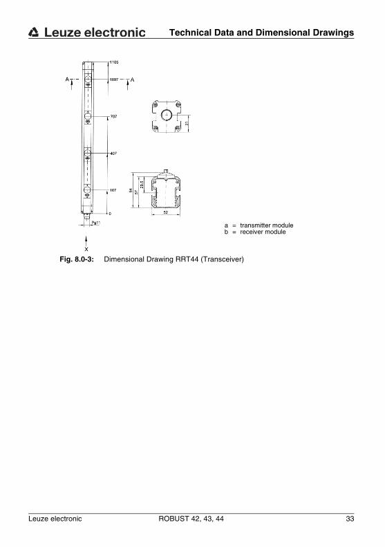
Fig. 8.0-3: Dimensional Drawing RRT44 (Transceiver)
a = transmitter moduleb = receiver module
Technical Data and Dimensional Drawings
34 ROBUST 42, 43, 44 Leuze electronic
DE
UT
SC
HE
NG
LIS
HF
RA
NÇ
AIS
ITA
LIA
NO
ES
PA
ÑO
LN
ED
ER
LA
ND
S
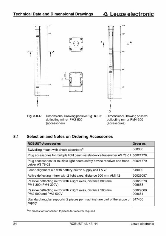
8.1 Selection and Notes on Ordering Accessories
1) 2 pieces for transmitter, 2 pieces for receiver required
Fig. 8.0-4: Dimensional Drawing passive deflecting mirror PM2-500 (accessories)
Fig. 8.0-5: Dimensional Drawing passive deflecting mirror PM4-300 (accessories)
ROBUST-Accessories Order nr.
Swivelling mount with shock absorbers1) 560300
Plug accessories for multiple light beam safety device transmitter AS 78-01 50021778
Plug accessories for multiple light beam safety device receiver and trans-ceiver AS 78-02
50021779
Laser alignment aid with battery-driven supply unit LA 78 549000
Active deflecting mirror with 2 light axes, distance 500 mm AMI 42 50029087
Passive deflecting mirror with 4 light axes, distance 300 mm PM4-300 (PM4-300V)
50029570 909663
Passive deflecting mirror with 2 light axes, distance 500 mm PM2-500 and PM2-500V
50029088 909661
Standard angular supports (2 pieces per machine) are part of the scope of supply
347450
Technical Data and Dimensional Drawings
Leuze electronic ROBUST 42, 43, 44 35
TN
T 3
5/7-
24V
DE
UT
SC
HE
NG
LIS
HF
RA
NÇ
AIS
ITA
LIA
NO
ES
PA
ÑO
LN
ED
ER
LA
ND
S
You can download this EC Declaration of Conformity from the Internet under:http://www.leuze.com/robust