Embed Size (px)
Citation preview
Review for Unit 42 & 43
00-When you are adding an air conditioning system to an original force air/furnace system you need to take account certain things.
When an air-conditioning system is to be added after the original furnace installation, the following considerations are the most important: the airflow, the ductwork, and the registers and grilles.
01-If your duct work size is too small, you can’t add the coil to it and expect to cool your house.
The fan is not moving enough air, velocity is not right, it going to get the freeze coil.
02-What is the rule of thumb for CFM per ton?
Typically air-conditioning systems require airflow of 400 CFM/ton.
03-If you got 12,000 CFM, how many tons of that?
12,000CFM ÷ 400 CFM/ton = 3 tons
04-If you got a 4 tons air conditioning system, what is the total capacity and BTUs on that of that system?
Air conditioning capacity is also measured in Btu/hr or watts. Large air conditioning systems are rated in tons. One ton of air conditioning is a unit of cooling equal to 12,000 Btu/hr or 3517 watts. 4 tons X 12,000 Btu/hr = 48,000 Btu/hr
05-When you’re looking air distribution system, thermal unit is called _______ are important factor.
06-You might want to know what a thermal couple & limit switch is.
07-You might want to know what a transformer and a fan relay is, and what they do in the system?
08-If you adding a cooling system to a heating system, what’re some of the things/components to add to that system to get it function?
09-If you got a package or self-contain system, normally the heating packages fuel by certain things but not one. Which one in not be? Oil
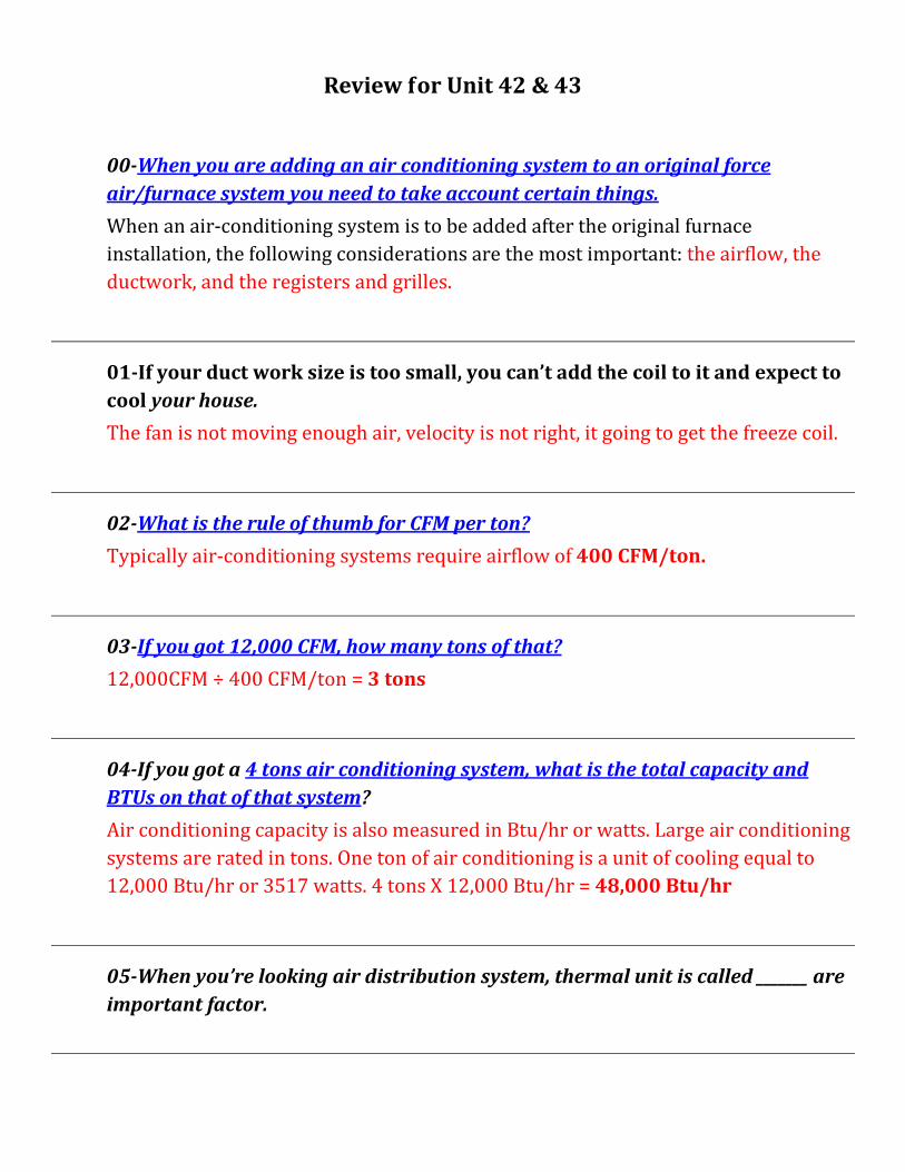
10-In the heat thing cycle on thermostat, when it sensing temperature, something happen, normally doesn’t happen in the cooling cycle, what is that? The heat anticipator, you might want to know what that is. What type of register in cooling anticipator? Fixed register
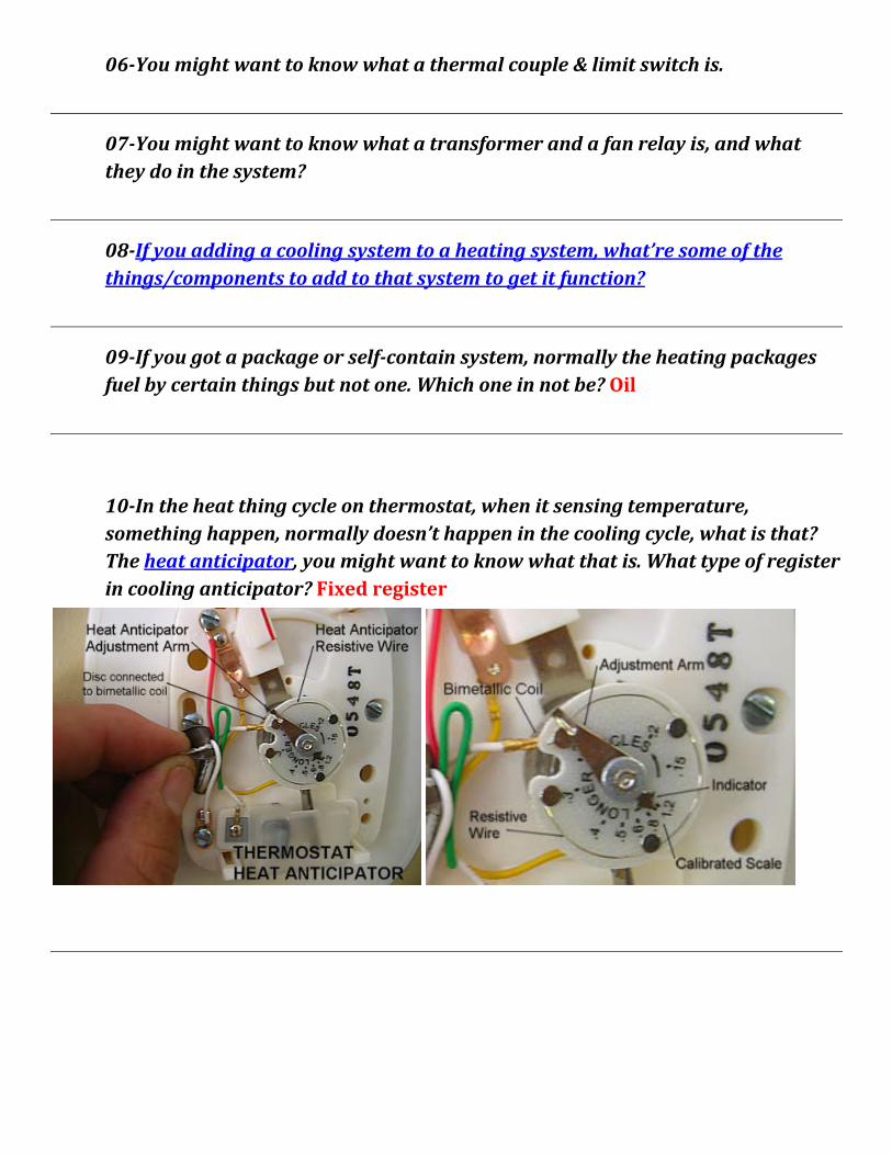
11- When you adding a cooling system and a second transformer. You have to parallel the original or add separate circuit.
(Drawn by Thomas)
12-You might want to know what happen during defrost cycle.
• The reversing valve switches the system into the cooling mode. This involves energizing the reversing valve coil for systems that fail in the heating mode or de-energizing the reversing valve coil for heat pump systems that fail in the cooling mode. The outdoor fan motor is functioning as the condenser coil during defrost.
• The outdoor fan motor is de-energized. With the fan not operating, more heat will be concentrated in the coil, allowing the frost to melt much faster than if the fan were operating.
• The indoor blower will remain on in most cases. Since the indoor coil is functioning as the evaporator in the defrost mode, the coil can freeze if the indoor blower is not operating.
• Some auxiliary heat is energized during defrost. This will help temper the cooler air being introduced to the occupied space during defrost. During defrost; the temperature of the occupied space should not be increased. If the temperature of the space is increased, the thermostat's set point may be reached and the heating cycle will end. If this happens, the defrost cycle will end as well and the ice removal process will stop.
When the heat pump system is in defrost with the auxiliary heat energized, the system is cooling and heating at the same time and is not efficient-so the defrost time must be held to a minimum. It must not operate except when needed. Demand defrosts means defrosting only when needed. Combinations of time, temperature, and pressure drop across the outdoor coil are used to determine when defrost should be started and stopped.
13-You might want to know air-to-air heat pump system is good for which part of the country.
14-How reversing valves work? [heating mode] [cooling mode]
15-You might want to understand the defrost cycle of heat pump.
16-You might want to understand where the suction line is connected.
17-You might want to understand pressure temperature defrost cycle control, when it activated, de-activated.
18-If you have the air blows too fast in the heating system. It is not going to heat, and what happen usually the combustion. It is start condensing.
19-You might want to understand if you have 2 transformers, whether or not you need an isolating sub-base.
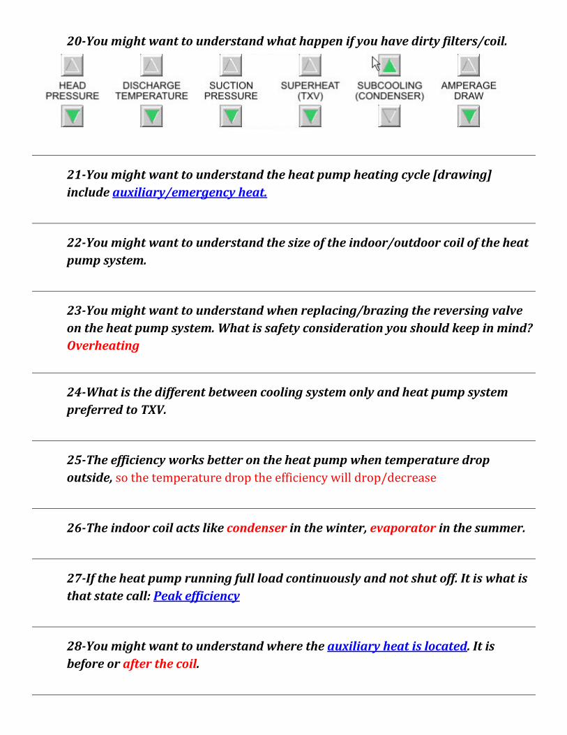
20-You might want to understand what happen if you have dirty filters/coil.
21-You might want to understand the heat pump heating cycle [drawing] include auxiliary/emergency heat.
22-You might want to understand the size of the indoor/outdoor coil of the heat pump system.
23-You might want to understand when replacing/brazing the reversing valve on the heat pump system. What is safety consideration you should keep in mind? Overheating
24-What is the different between cooling system only and heat pump system preferred to TXV.
25-The efficiency works better on the heat pump when temperature drop outside, so the temperature drop the efficiency will drop/decrease
26-The indoor coil acts like condenser in the winter, evaporator in the summer.
27-If the heat pump running full load continuously and not shut off. It is what is that state call: Peak efficiency
28-You might want to understand where the auxiliary heat is located. It is before or after the coil.
29-Drawing the heat pump system for heating cycle, consisted of frost cycle, what happen when the defrost cycle is on and what keep the cold air blow into the space. Also explain the heat anticipator does on your thermostat.
30-Drawing the heat pump system for cooling cycle.
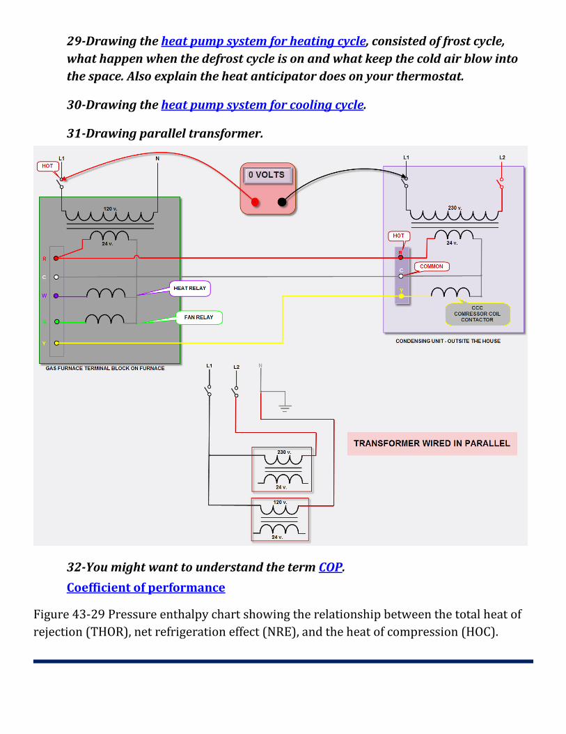
31-Drawing parallel transformer.
32-You might want to understand the term COP.
Coefficient of performance
Figure 43-29 Pressure enthalpy chart showing the relationship between the total heat of rejection (THOR), net refrigeration effect (NRE), and the heat of compression (HOC).
Unit 42 – Electric, Gas, and Oil Heat with Electric Air Conditioning - OBJECTIVES
*describe year-round air conditioning.
*discuss the three typical year-round air-conditioning systems.
*list the five ways to condition air.
*determine airflow for a cooling system.
*describe why a heating system normally uses less air than a cooling system.
*explain two methods used to vary the airflow in the heating season from that in the cooling season.
*describe two types of control-voltage power supplies used in add-on air conditioning.
*describe add-on air conditioning.
*explain package all-weather systems.
42.1 COMFORT All YEAR
Year-round air conditioning describes a system that conditions the living space for heating and cooling throughout the year.
The most common are electric air conditioning with electric resistance heat, electric air conditioning with gas heat, and electric air conditioning with oil heat.
42.2 FIVE PROCESSES FOR CONDITIONING AIR
Air is conditioned when it is heated, cooled, humidified, de-humidified, or cleaned.
This unit describes how air is heated and cooled with the same system.
The systems discussed in is unit are called forced-air systems.
Air is distributed rough ductwork to the conditioned space.
The fan is normally a component of the heating system and provides the force to move the air through the duct system.
A typical system may have an electric, gas, or oil furnace with an evaporator in the airstream for cooling.
42.3 ADD-ON AIR CONDITIONING
Many systems are installed in stages.
The furnace may be installed when the structure is built. The air conditioning may be added at the same time or later (add-on air conditioning).
Air-conditioning systems must have the correct air circulation.
Typically, they require an airflow of 400 cfm/ton, which is more than needed for an average forced-air heating system. [Return to Q. # 02]
A 3-ton cooling system, for example, requires 1200 cfm. The furnace on an existing heating system where 3 tons of cooling are added must be able to furnish the required amount of air, and the ductwork must be sized for the airflow. [Return to Q. # 03]
The air-conditioning load may be reduced by attic ventilation, insulation, storm windows, shades, or awnings.

42.5 EVALUATION Of AN EXISTING DUCT SYSTEM
When an air-conditioning system is to be added after the original furnace installation, the following considerations are the most important: the airflow, the ductwork, and the registers and grilles. [Return to Q. # 00]
A survey of the existing "heat only" duct system may show that the return air is undersized, and an extra return duct may be required.
The grilles and registers used for the final air distribution are important also.
42.6 COOLING VERSUS HEATING AIR QUANTITY
It is usually desirable to have less airflow in the winter, so the air that is entering the room through the registers will be hot.
If the airflow of 400 cfm/ton of air conditioning is used in the winter, the air may create drafts of slightly warm air instead of hot air.
Correct airflow is necessary for gas and oil furnaces for correct venting.
Too much air will cause products of combustion to be too cool and condensation may occur.
Changing the air volume is accomplished with dampers or a multispeed fan.
Dampers are sometimes installed by the original contractor.
They have summer and winter positions.
Someone must change the damper position for each change of season.
Because this is often overlooked, some contractors install a low-voltage end switch that will not allow the cooling contactor to be energized unless the damper is in the summer position.
Multi-speeds from the fan may be achieved by adjusting the fan motor pulley or using multispeed motors.
When the pulley must be adjusted to change fan speeds for a new season, a service technician must visit the location twice a year
42.8 TWO LOW-VOLTAGE POWER SUPPLIES
The control circuit may have more than one low-voltage power supply, which can cause much confusion for the technician trying to troubleshoot a problem.
If the heating system was installed first and the air conditioning added later, there may be two power supplies.
The furnace must have a low voltage transformer to operate in the heating mode.
When the air conditioning was added, a transformer may have been furnished with it because the air-conditioning manufacturer did not know if the low-voltage power supply furnished with the furnace was adequate.
Air-conditioning systems usually require a 40- VA transformer to supply enough current to energize the compressor contactor coil and the fan relay coil.
Most basic furnaces can operate on a 25-VA transformer and may be furnished with one.
When two power supplies are used, a special arrangement must be made in the thermostat and sub-base.
In one arrangement the two circuits are separated; in the other the two transformers are wired in parallel by phasing them
42.9 PHASING TWO LOW-VOLTAGE TRANSFORMERS
Transformer:
When the two transformers are wired in parallel, they must be kept in phase or the transformers will have opposing phases, Figure 42-11.
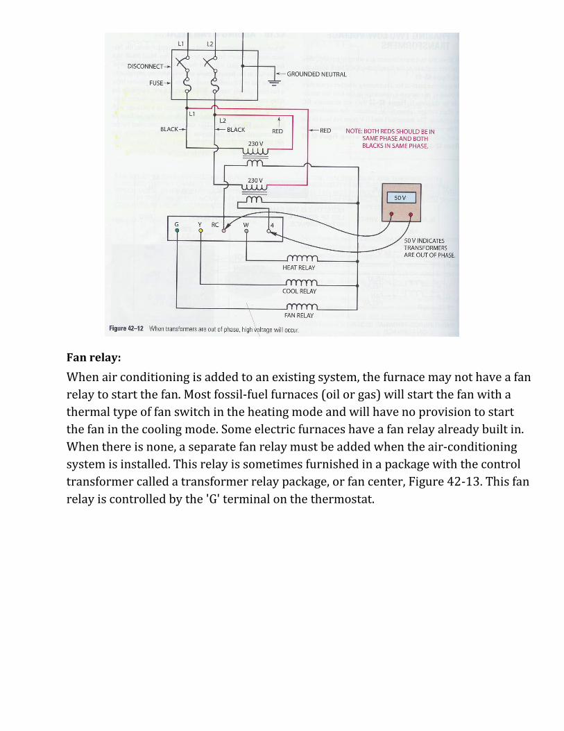
The preferred method for determining whether or not they are in phase is to connect a voltmeter to the two hot terminals. In the diagram in Figure 42-12 they are terminals RC and 4. High voltage, about 50 V, indicates the transformers are out of phase. The meter will read 0 V from hot lead to hot lead if the transformers are in phase. If out of phase, it can be corrected with the primary or secondary wiring, Figure 42-11 and Figure 42-12.
Fan relay:
When air conditioning is added to an existing system, the furnace may not have a fan relay to start the fan. Most fossil-fuel furnaces (oil or gas) will start the fan with a thermal type of fan switch in the heating mode and will have no provision to start the fan in the cooling mode. Some electric furnaces have a fan relay already built in. When there is none, a separate fan relay must be added when the air-conditioning system is installed. This relay is sometimes furnished in a package with the control transformer called a transformer relay package, or fan center, Figure 42-13. This fan relay is controlled by the 'G' terminal on the thermostat.
Summary
Summer air conditioning is sometimes added to an existing heating system. This is called add-on cooling.
Different air volumes are sometimes desirable for the heating and cooling seasons. The air in the heating season is warmer at the terminal units when the air volume is reduced in the heating season.
Different air volumes are accomplished with dampers and variable fan speeds.
The control circuit may have two transformers--one furnished with the furnace and one with the air-conditioning unit. When two power supplies (transformers) exist, the two may be kept separated in the thermostat, or they may be wired in parallel and in phase.
Package all-weather systems normally consist of gas heat and electric air conditioning or electric heat and electric air conditioning.
Unit 43 – Air Source Heat Pump - OBJECTIVES
*describe a reverse-cycle heat pump.
*list the components of a reverse-cycle heat pump.
*explain a four-way valve.
*state the various heat sources for heat pumps.
*compare electric heat to heat with a heat pump.
*state how heat pump efficiency is rated.
*determine by the line temperatures whether a heat pump is in cooling or heating.
*discuss the terminology of heat pump components.
*define coefficient of performance,
*explain auxiliary heat.
*describe the control sequence on an air-to-air heat pump.
*describe techniques being used to improve the efficiency of heat pump systems.
*discuss recommended preventive maintenance procedures for heat pump systems.
43.1 REVERSE-CYCLE REFRIGERATION
The heat pump is a refrigeration system that can pump heat two ways.
Since it has the ability to pump heat into as well as out of a structure, the heat pump system can provide both heating and cooling.
These four components: the evaporator, the condenser, the compressor, and the metering device-are essential to compression-cycle refrigeration equipment.
The same components are in a heat pump system along with the four-way valve, which is used to switch the unit between the heating and cooling modes of operation.
By changing the mode of operation of a heat pump system, the functions of the indoor and outdoor coils change as well.
In the cooling mode, the indoor coil acts as the evaporator and the outdoor coil functions as the condenser.
In the heating mode, the indoor coil functions as the condenser and the outdoor coil operates as the evaporator.
43.2 HEAT SOURCES FOR WINTER
In summer the heat pump acts like a conventional air conditioner and removes heat from the house and deposits it outside.
From the outside an air-to-air heat pump looks like a central cooling air conditioner.
The term "air to air" indicates the source of heat while the system is operating in the heating mode and the medium that is ultimately being treated.
The first "air" represents the heat source, while the second "air" represents the medium being heated.
An "air-to-water" heat pump uses "air" to heat "water."
Water-source heat pumps use water as the heat source in the heating mode and can be "water-to-water" or "water-to-air."
The water-to-air heat pump, therefore, uses water as the heat source to heat air.
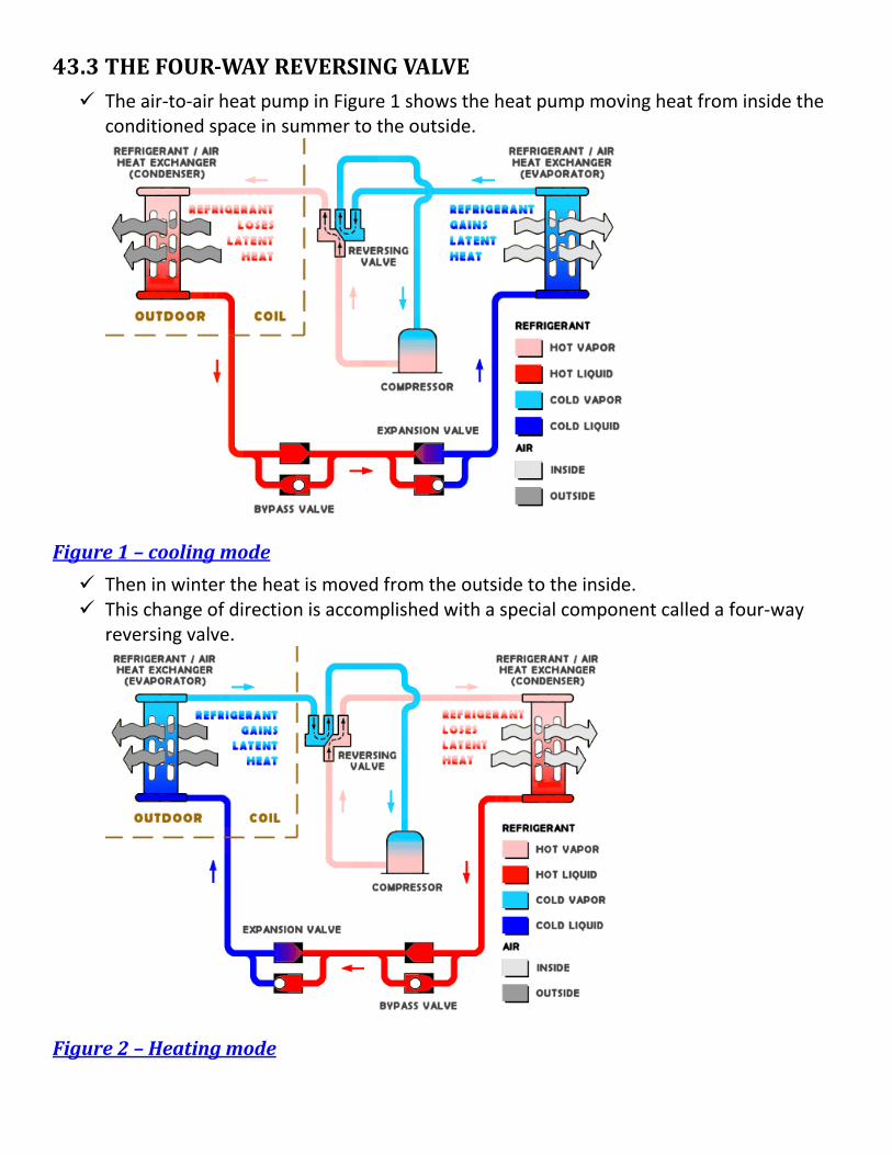
43.3 THE FOUR-WAY REVERSING VALVE The air-to-air heat pump in Figure 1 shows the heat pump moving heat from inside the
conditioned space in summer to the outside.
Figure 1 – cooling mode
Then in winter the heat is moved from the outside to the inside. This change of direction is accomplished with a special component called a four-way
reversing valve.
Figure 2 – Heating mode
This valve can best be described in the following way. The heat absorbed into the refrigeration system is pumped through the system with the
compressor. The heat is contained and concentrated in the discharge gas. The four-way valve diverts the discharge gas and the heat in the proper direction to
either heat or cool the conditioned space. This valve is controlled by the space temperature thermostat, which positions it to
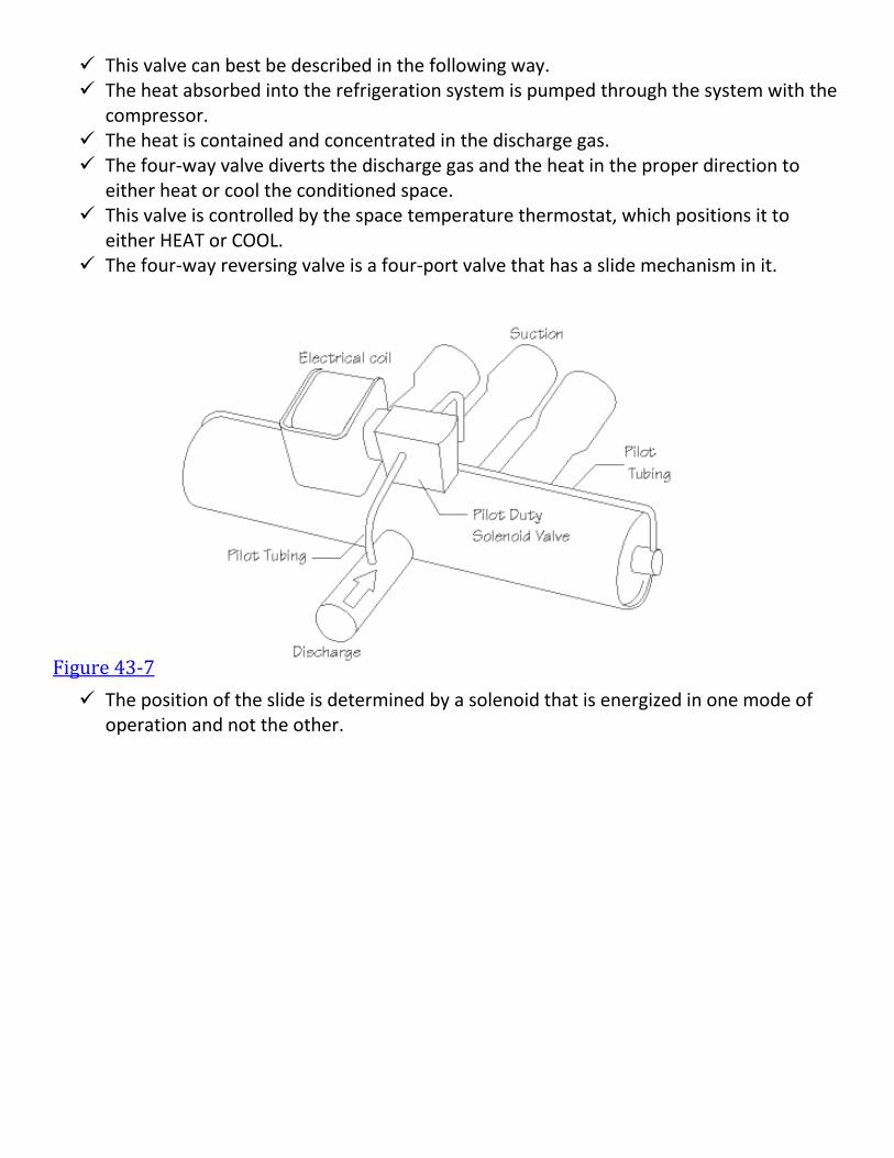
either HEAT or COOL. The four-way reversing valve is a four-port valve that has a slide mechanism in it.
Figure 43-7
The position of the slide is determined by a solenoid that is energized in one mode of operation and not the other.
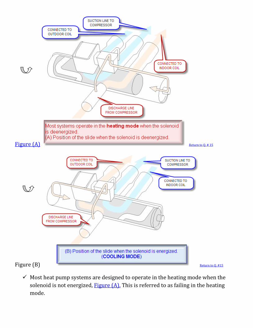
Figure (A) Return to Q. # 15
Figure (B) Return to Q. #15
Most heat pump systems are designed to operate in the heating mode when the solenoid is not energized, Figure (A). This is referred to as failing in the heating mode.
Typical reversing valves have one isolated port on one side and the remaining three ports on the other. The isolated port is where the hot gas from the compressor enters the valve.
Figure 43-7 indicates the piping connections on the valve. Depending on the position of the slide, the hot gas will be directed to either the outdoor coil or the indoor coil. In either case, the coil that accepts the hot gas from the compressor is functioning as the condenser coil.
Note that in Figure (A) the hot gas enters the valve at the bottom and is directed to the right-hand port, which is connected to the indoor coil. Since the indoor coil is receiving the hot gas from the compressor, the indoor coil is the condenser and the system is operating in the heating mode.
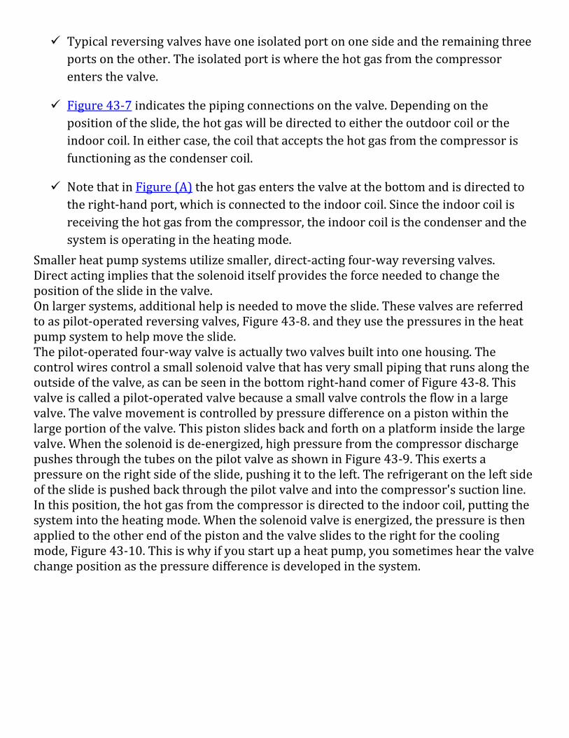
Smaller heat pump systems utilize smaller, direct-acting four-way reversing valves. Direct acting implies that the solenoid itself provides the force needed to change the position of the slide in the valve. On larger systems, additional help is needed to move the slide. These valves are referred to as pilot-operated reversing valves, Figure 43-8. and they use the pressures in the heat pump system to help move the slide. The pilot-operated four-way valve is actually two valves built into one housing. The control wires control a small solenoid valve that has very small piping that runs along the outside of the valve, as can be seen in the bottom right-hand comer of Figure 43-8. This valve is called a pilot-operated valve because a small valve controls the flow in a large valve. The valve movement is controlled by pressure difference on a piston within the large portion of the valve. This piston slides back and forth on a platform inside the large valve. When the solenoid is de-energized, high pressure from the compressor discharge pushes through the tubes on the pilot valve as shown in Figure 43-9. This exerts a pressure on the right side of the slide, pushing it to the left. The refrigerant on the left side of the slide is pushed back through the pilot valve and into the compressor's suction line. In this position, the hot gas from the compressor is directed to the indoor coil, putting the system into the heating mode. When the solenoid valve is energized, the pressure is then applied to the other end of the piston and the valve slides to the right for the cooling mode, Figure 43-10. This is why if you start up a heat pump, you sometimes hear the valve change position as the pressure difference is developed in the system.
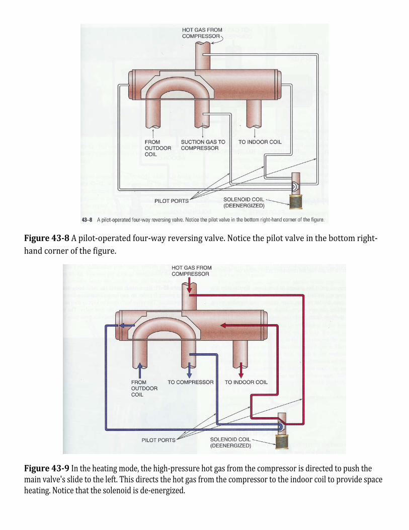
Figure 43-8 A pilot-operated four-way reversing valve. Notice the pilot valve in the bottom right-hand corner of the figure.
Figure 43-9 In the heating mode, the high-pressure hot gas from the compressor is directed to push the main valve's slide to the left. This directs the hot gas from the compressor to the indoor coil to provide space heating. Notice that the solenoid is de-energized.
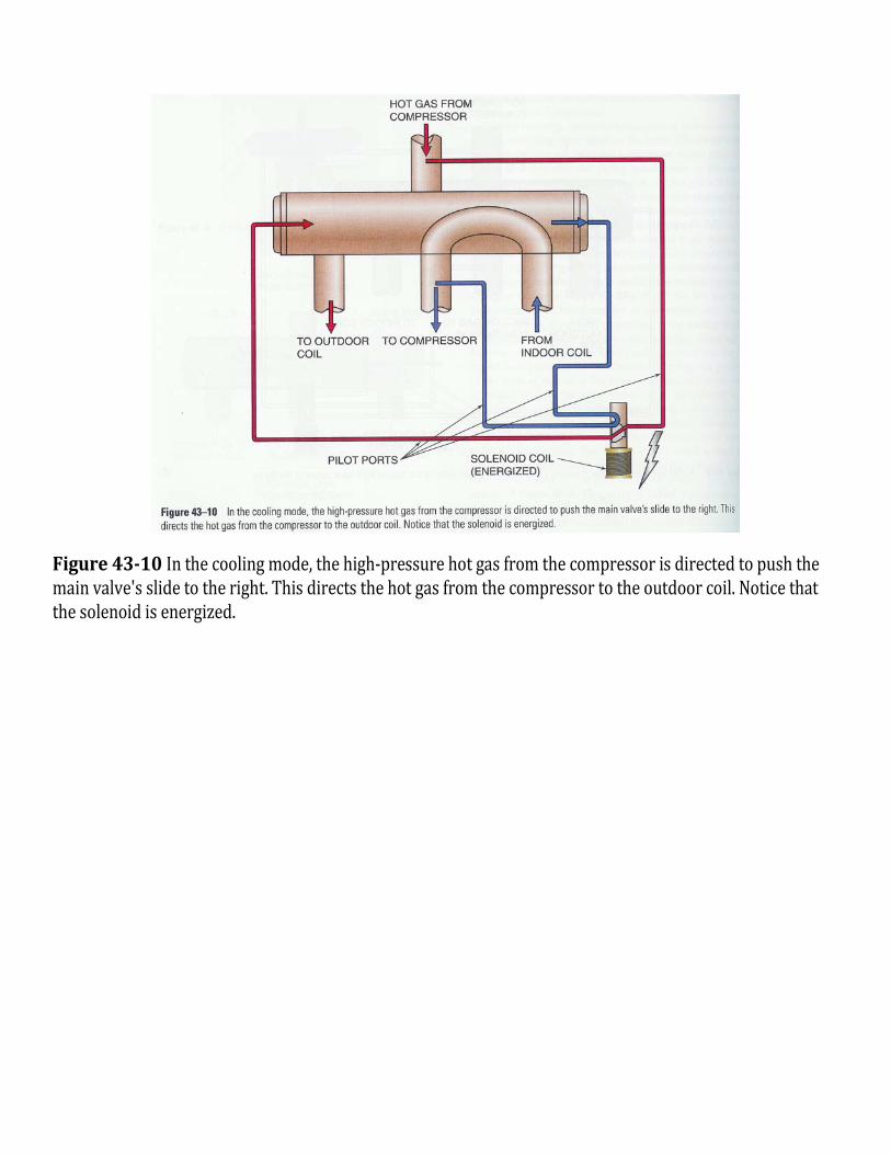
Figure 43-10 In the cooling mode, the high-pressure hot gas from the compressor is directed to push the main valve's slide to the right. This directs the hot gas from the compressor to the outdoor coil. Notice that the solenoid is energized.
43.4 THE AIR-TO-AIR HEAT PUMP
The air-to-air heat pump resembles the central air-conditioning system. It has indoor and outdoor system components. When discussing typical air-conditioning systems, these components are often called the evaporator (indoor unit) and the condenser (outdoor unit). This terminology will work for air conditioning but not for a heat pump.
The coil that serves the inside of the house is called the indoor coil. The unit outside the house is called the outdoor unit and contains the outdoor coil. The reason is that the indoor coil is a condenser in the heating mode and an evaporator in the cooling mode. The outdoor coil is a condenser in the cooling mode and an evaporator in the heating mode. This is all determined by which way the hot gas is flowing. In winter the hot gas is flowing toward the indoor unit and will give up heat to the conditioned space. The heat must come from the outdoor unit, which is the evaporator.
43.11 ORIFICE METERING DEVICES
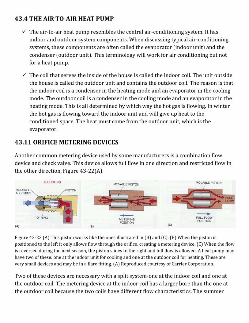
Another common metering device used by some manufacturers is a combination flow device and check valve. This device allows full flow in one direction and restricted flow in the other direction, Figure 43-22(A).
Figure 43-22 (A) This piston works like the ones illustrated in (B) and (C). (B) When the piston is positioned to the left it only allows flow through the orifice, creating a metering device. (C) When the flow is reversed during the next season, the piston slides to the right and full flow is allowed. A heat pump may have two of these: one at the indoor unit for cooling and one at the outdoor coil for heating. These are very small devices and may be in a flare fitting. (A) Reproduced courtesy of Carrier Corporation.
Two of these devices are necessary with a split system-one at the indoor coil and one at the outdoor coil. The metering device at the indoor coil has a larger bore than the one at the outdoor coil because the two coils have different flow characteristics. The summer
cycle uses more refrigerant in normal operation. When this device is used, a bi-flow filter drier is normally used in the liquid line when field repairs are done.
All of these components may be found on water-to-air heat pumps or air-to-air heat pumps. The components that control and operate the systems are much the same.
43.13 APPLICATION OF THE AIR-TO-AIR HEAT PUMP
Air-to-air systems are normally installed in milder climates in the "heat pump belt," which is basically those parts of the United States where winter temperatures can be as low as 10°F.
The reason for this geographical line is the characteristic of the air-to-air heat pump. It absorbs heat from the outside air; as the outside air temperature drops, it is more difficult to absorb heat from it. For example, the evaporator must be cooler than the outside air for the air to transfer heat into the evaporator. Normally, in cold weather, the heat pump evaporator will be about 20°F to 25°F cooler than the air from which it is absorbing heat. We will use 25°F temperature difference (TD) in this text as the example, Figure 43-27. On a 10°F day the heat pump evaporator will be boiling (evaporating) the liquid refrigerant at 25°F lower than the 10°F air. This means that the boiling refrigerant temperature will be -15°F. As the evaporator temperature goes down, the compressor loses capacity. The compressor is a fixed-size pump. It will have more capacity on a 30°F day than on a 10°F day. The heat pump loses capacity as the capacity need of the structure increases. On a 10 °F day the structure needs more capacity than on a 30°F day, but the heat pump's capacity is less. Thus, the heat pump must have help.
43.14 AUXILIARY HEAT
In an air-to-air heat pump system, the help that the heat pump gets is called auxiliary heat. The heat pump itself is the primary heat, and the auxiliary heat may be electric, oil, or gas. Electric auxiliary heat is the most popular because it is easier to adapt a heat pump to an electric system.
The structure that a heat pump is intended to heat has a different requirement for every outside temperature level. For example, a house might require 30,000 Btu of heat during the day when the outside temperature is 30°F. As the outside temperature drops, the structure requires more heat. It might need 60,000 Btu of heat in the middle of the night when the temperature has dropped to 10°F. The heat pump could have a capacity of 30,000 Btu/h at 30°F and 20,000 Btu/h at 0°F. The difference of 40,000 Btu/h must be made up with auxiliary heat.
43.15 BALANCE POINT
The balance point occurs when the heat pump can pump in exactly as much heat as the structure is leaking out. At this point the heat pump will completely heat the structure by running continuously. Above this point the heat pump will cycle off and on. Below this point the heat pump will run continuously but will not be able to maintain the desired temperature. Although the auxiliary heat portion of a heat pump system will be operational at some temperature above the balance point, it is impossible for a heat pump system to satisfy the heating requirements of a structure without auxiliary heat if the temperature falls below the balance point
43.16 COEFFICIENT OF PERFORMANCE
To understand the efficiency of an air-to-air heat pump, you need an understanding of electric heat. A customer receives 1 W of usable heat for each watt of energy purchased from the power company while using electric resistance heat. This is called 100% efficient or a coefficient of performance (COP) of 1: 1. The output is the same as the input. With a heat pump the efficiency may be improved as much as 3.5: 1 for an air-to-air system with typical equipment. When the 1 W of electrical energy is used in the compression cycle to absorb heat from the outside air and pump this heat into the structure, the unit could furnish 3.5 W of usable heat. Thus its COP is 3.5: 1, or it can be thought of as 350% efficient.
To provide some insight into why the COP of a heat pump system is so high, it is necessary to take a look at the pressure enthalpy chart shown in Figure 43-29. For a system that provides cooling, the COP is defined as
COP = Net refrigeration effect ÷ Heat of compression
From the values shown in Figure 43-29, the net refrigeration effect (NRE) is 75 Btu/lb (115 Btu/lb - 40 Btu/lb) and the heat of compression is 25 Btu/lb (140 Btu/lb - 115 Btu/lb). From this we can determine the COP as being 3 (75 Btu/lb ÷ 25 Btu/lb). For a system that is providing cooling, the NRE is what the occupant of the structure is benefiting from, since the refrigeration effect is what is taking place in the evaporator, or cooling, coil.
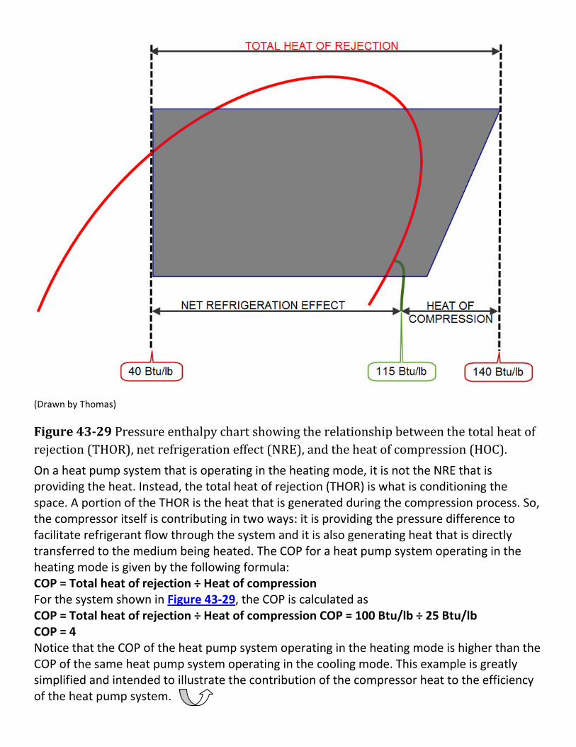
(Drawn by Thomas)
Figure 43-29 Pressure enthalpy chart showing the relationship between the total heat of rejection (THOR), net refrigeration effect (NRE), and the heat of compression (HOC). On a heat pump system that is operating in the heating mode, it is not the NRE that is providing the heat. Instead, the total heat of rejection (THOR) is what is conditioning the space. A portion of the THOR is the heat that is generated during the compression process. So, the compressor itself is contributing in two ways: it is providing the pressure difference to facilitate refrigerant flow through the system and it is also generating heat that is directly transferred to the medium being heated. The COP for a heat pump system operating in the heating mode is given by the following formula: COP = Total heat of rejection ÷ Heat of compression For the system shown in Figure 43-29, the COP is calculated as COP = Total heat of rejection ÷ Heat of compression COP = 100 Btu/lb ÷ 25 Btu/lb COP = 4 Notice that the COP of the heat pump system operating in the heating mode is higher than the COP of the same heat pump system operating in the cooling mode. This example is greatly simplified and intended to illustrate the contribution of the compressor heat to the efficiency of the heat pump system.
43.18 THE INDOOR UNIT
The indoor unit of an air-to-air system may be an electric furnace with a heat pump indoor coil where the summer air-conditioning evaporator would be placed. The outdoor unit may resemble a cooling condensing unit.
The indoor unit is the part of the system that circulates the air for the structure.
It contains the fan and coil. The airflow pattern may be upflow, downflow, or horizontal to serve different applications.
Coil placement in the airstream is important in the indoor unit.
The electric auxiliary heat and the primary heat (the heat pump) may need to operate at the same time in weather below the balance point of the house.
The refrigerant coil must be located in the airstream before the auxiliary heating coil. Otherwise, heat from the auxiliary unit will pass through the refrigerant coil when both are operating in winter. [Return to Q. # 28]
If the auxiliary heat is operating and is located before the heat pump coil, the head pressure will be too high and could rupture the coil or bum the compressor motor. Remember, the coil is operating as a condenser in the heating mode. It rejects heat from the refrigeration system, so any heat added to it will cause the head pressure to rise.
The indoor unit may be a gas or oil furnace. If this is the case, the indoor coil must be located in the outlet airstream of the furnace. When the auxiliary heat is gas or oil, the heat pump does not run while the auxiliary heat is operating. If it is not located after the furnace heat exchanger it would sweat in summer. The indoor coil would be operating as an evaporator in the summer, and the outlet air temperature could be lower than the dew point temperature of the air surrounding the heat exchanger. Most local codes will not allow a gas or oil heat exchanger to be located in a cold airstream for this reason. When the auxiliary heat is gas or oil, special control arrangements must be made so that the heat pump will not operate while the gas or oil heat is operating. When a heat pump is added onto an electric furnace and the coil must be located after the heat strips, follow the same rules as for gas or oil.
43.21 PACKAGE AIR-TO-AIR PUMPS
Package air-to-air heat pumps are much like package air conditioners. They look alike and are installed in the same way. Therefore, give the same considerations to the prevailing wind and water conditions.
The heat pump outdoor coil must have drainage in summer and winter. The package heat pump has all of the components in one housing and is easy to service.
They have optional electric heat compartments that usually accept different electric heat sizes from 5000 W (5 kW) to 25,000 W (25 kW).
The metering devices used for package air-to-air heat pumps are much like those for split systems. Some manufacturers use a common metering device for the indoor and outdoor coils because the two are so close together.
When one metering device is used, it must be able to meter both ways at a different rate in each direction because a different amount of refrigerant is used in the summer evaporator (indoor coil) than in the winter evaporator (outdoor coil).
43.22 CONTROLS THE AIR-TO-AIR HEAT PUMP
The air-to-air heat pump is different from any other combination of heating and cooling equipment. The following items must be controlled at the same time for the heat pump to be efficient: space temperature, defrost cycle, indoor fan, the compressor, the outdoor fan, auxiliary heat, and emergency heat.
The space temperature for an air-to-air heat pump is not controlled in the same way as a typical heating and cooling system. There are actually two complete heating systems and one cooling system. The two heating systems are the refrigerated heating cycle from the heat pump and the auxiliary heat from the supplemental heating system-electric, oil, or gas. The auxiliary heating system may be operated as a system by itself if the heat pump fails. When the auxiliary heat becomes the primary heating system because of heat pump failure, it is called emergency heat and is normally operated only long enough to get the heat pump repaired. The reason is that the COP of the auxiliary heating system is not as good as the COP of the heat pump.
The space-temperature thermostat is the key to controlling the system. It is normally a two-stage heating and two-stage cooling type of thermostat used exclusively for heat pump applications. Other variations in the thermostat concern the number of stages of heating or cooling.
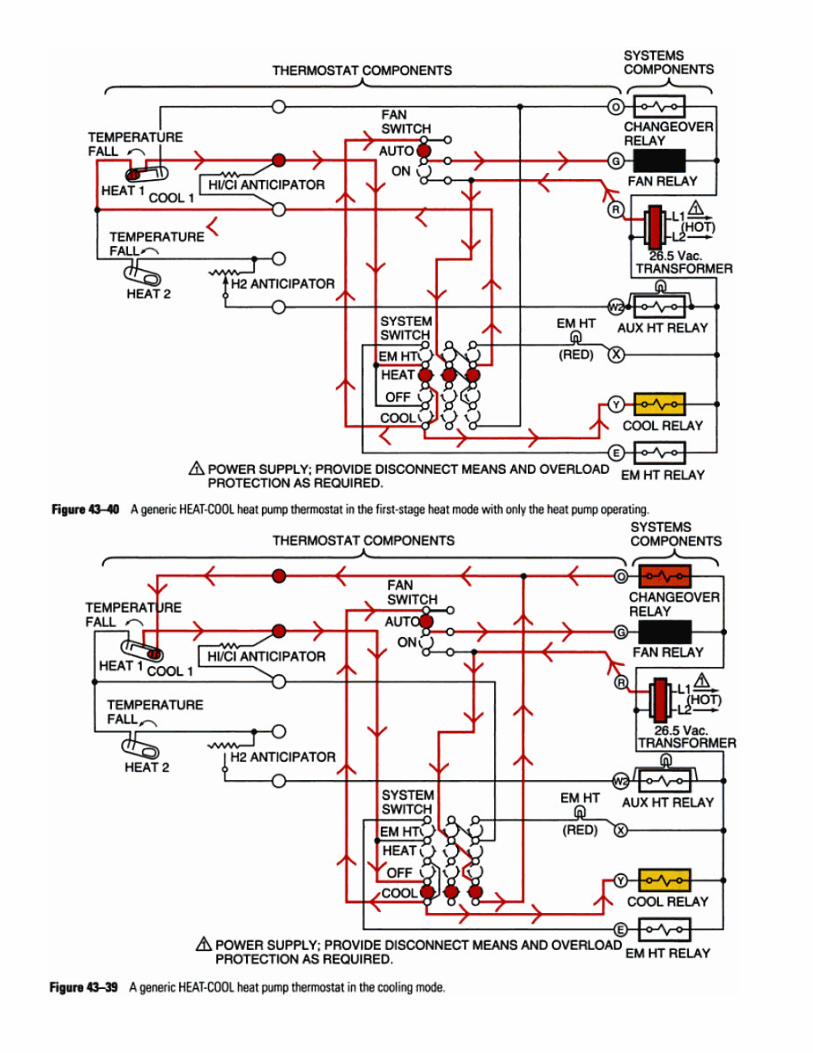

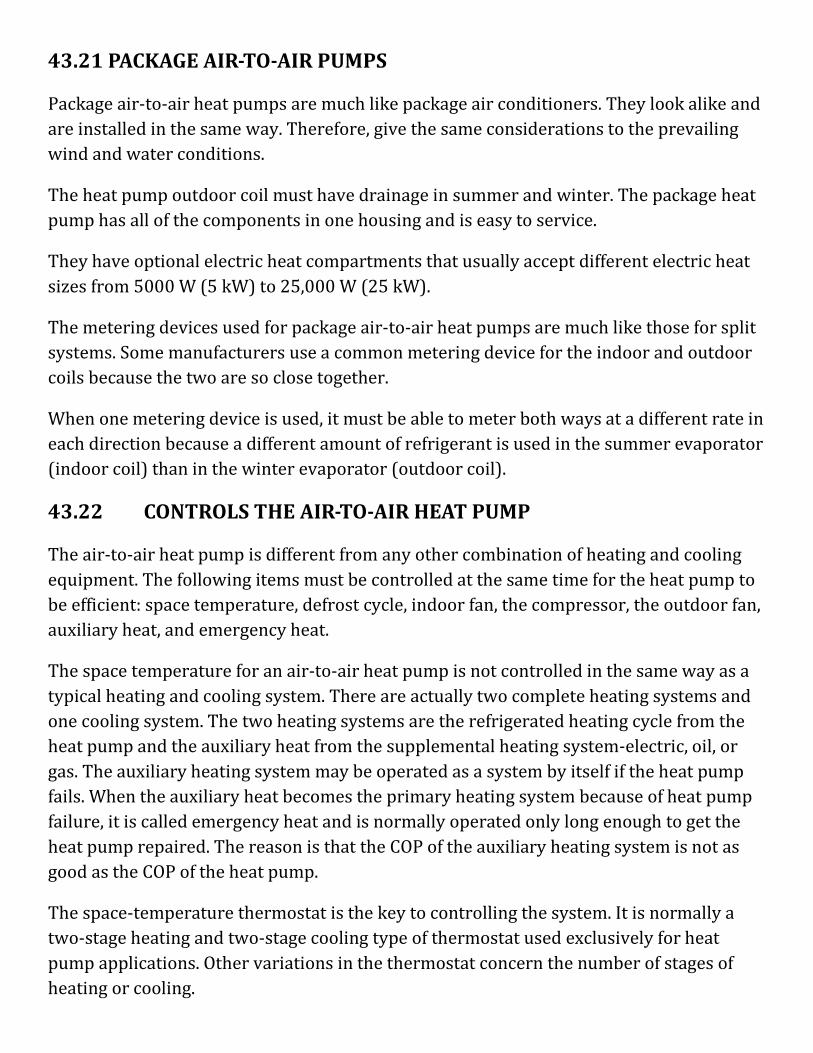
Cooling Cycle Control
When the first -stage bulb of the thermostat closes its contacts (on a rise in space temperature), the four-way reversing valve solenoid coil is energized, Figure 43-41.
When the space temperature rises about 1°F, the second-stage cooling contacts of the thermostat close. The second-stage contacts energize the compressor contactor coil and the indoor fan relay coil to start the compressor, outdoor fan, and the indoor fan, Figure 43-42. When the compressor starts the second stage of operation, it diverts the hot gas from the compressor to the outdoor coil, and the system is in the cooling cycle.
43.23 THE DEFROST CYCLE
While operating in the heating mode, the outdoor coil functions as the evaporator. When the outside ambient temperature is warm-above about 50°F -the evaporator saturation temperature will be above freezing and the coil will not freeze. When the outside ambient temperature drops below 50°F, the outdoor coil can begin to freeze, since the evaporator coil operates at a temperature that is about 20°F to 25°F below the outside ambient temperature. If the frost on the coil is allowed to accumulate, system performance will be
reduced. The defrost cycle is used to defrost the ice from the outdoor coil during winter heating operation.
Remember that the outdoor coil must be colder than the outside air if the coil is going to absorb heat from the outside air. The need for defrost varies with the outdoor
How is Defrost Accomplished?
In order for the heat pump system to operate in the defrost mode, a number of things must take place:
• The reversing valve switches the system into the cooling mode. This involves energizing the reversing valve coil for systems that fail in the heating mode or de-energizing the reversing valve coil for heat pump systems that fail in the cooling mode. The outdoor fan motor is functioning as the condenser coil during defrost.
• The outdoor fan motor is de-energized. With the fan not operating, more heat will be concentrated in the coil, allowing the frost to melt much faster than if the fan were operating.
• The indoor blower will remain on in most cases. Since the indoor coil is functioning as the evaporator in the defrost mode, the coil can freeze if the indoor blower is not operating.
• Some auxiliary heat is energized during defrost. This will help temper the cooler air being introduced to the occupied space during defrost. During defrost; the temperature of the occupied space should not be increased. If the temperature of the space is increased, the thermostat's set point may be reached and the heating cycle will end. If this happens, the defrost cycle will end as well and the ice removal process will stop.
When the heat pump system is in defrost with the auxiliary heat energized, the system is cooling and heating at the same time and is not efficient-so the defrost time must be held to a minimum. It must not operate except when needed. Demand defrosts means defrosting only when needed. Combinations of time, temperature, and pressure drop across the outdoor coil are used to determine when defrost should be started and stopped.
The factors that vary the operating cost of a piece of equipment are the number of defrosts per season, length of defrost, and whether the manufacturer tempers the air to the conditioned space during defrost with auxiliary heat. Re-member, the unit will be in the cooling mode and blowing cold air during defrosts; some owners will object to that. If the
manufacturer can get the equipment rated without the auxiliary heat, the rating will be better. [Return to Q. # 15]
Initiating the Defrost Cycle
Starting the defrost cycle with the correct frost buildup is desirable. Manufacturers design the systems to start defrost as close as possible to when the coil builds frost that affects performance. Some manufacturers use time and temperature to start defrost. This is called time and temperature initiated and is performed with a timer and temperature-sensing device. The timer closes a set of contacts for 10 to 20 sec for a trial defrost every 30, 60, or 90 min. The timer contacts are in series with the temperature sensor contacts so that both must be made at the same time. This means that two conditions must be met before defrost can start, Figure 43-52. In operation, every time the allotted time delay has elapsed, the timer will attempt to bring the heat pump system into defrost. If the temperature sensor determines that there is ice on the coil, defrost will start. The sensing device contacts will close if the coil temperature is as low as 25°F, and defrost will start. Figure 43-53 shows a typical timer and a sensor. Typically, the timer runs any time the compressor runs, even in the cooling mode.
Another common method of starting defrosts uses an air-pressure switch that measures the air pressure drop across the outdoor coil. When the unit begins to accumulate ice, a pressure drop occurs and the air switch contacts close. This can be wired in conjunction with the timer and temperature sensor to ensure that an actual ice buildup is on the coil. The combination of time and temperature only ensures that time has passed and the coil is cold enough to actually accumulate ice. It does not actually sense an ice thickness. It can be more efficient to defrost when an actual buildup of ice exists, Figure 43-54. [Return to Q. # 17]
Terminating the Defrost Cycle
Terminating the defrost cycle at the correct time is just as important as starting defrost only when needed. This is done in several ways. Time and temperature was the terminology used to start defrost. Time or temperature terminated is the terminology used to terminate one type of defrost cycle. The difference is that two conditions must be satisfied to start defrost, and either one of two conditions can terminate defrost. After defrost has started, time or temperature can terminate it. For example, if the defrost temperature sensor warms up to the point that it is obvious that ice is no longer on the coil and its contacts break, defrost will stop. This temperature termination is normally 50°F at the location of the temperature sensor. If the contacts do not open because it is too cold outside, the timer will terminate defrost within a predetermined time period. Normally, the maximum time the timer will allow for defrost is 10 min, Figure 43-55.
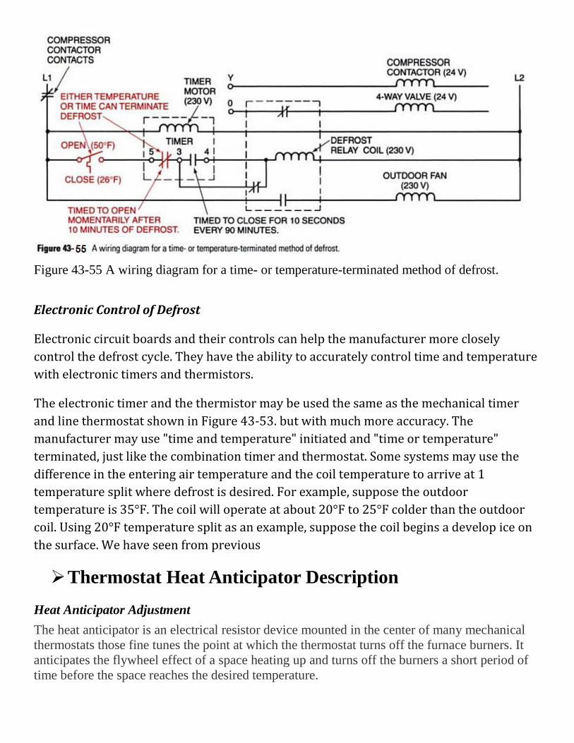
Figure 43-55 A wiring diagram for a time- or temperature-terminated method of defrost.
Electronic Control of Defrost
Electronic circuit boards and their controls can help the manufacturer more closely control the defrost cycle. They have the ability to accurately control time and temperature with electronic timers and thermistors.
The electronic timer and the thermistor may be used the same as the mechanical timer and line thermostat shown in Figure 43-53. but with much more accuracy. The manufacturer may use "time and temperature" initiated and "time or temperature" terminated, just like the combination timer and thermostat. Some systems may use the difference in the entering air temperature and the coil temperature to arrive at 1 temperature split where defrost is desired. For example, suppose the outdoor temperature is 35°F. The coil will operate at about 20°F to 25°F colder than the outdoor coil. Using 20°F temperature split as an example, suppose the coil begins a develop ice on the surface. We have seen from previous
Thermostat Heat Anticipator Description Heat Anticipator Adjustment The heat anticipator is an electrical resistor device mounted in the center of many mechanical thermostats those fine tunes the point at which the thermostat turns off the furnace burners. It anticipates the flywheel effect of a space heating up and turns off the burners a short period of time before the space reaches the desired temperature.
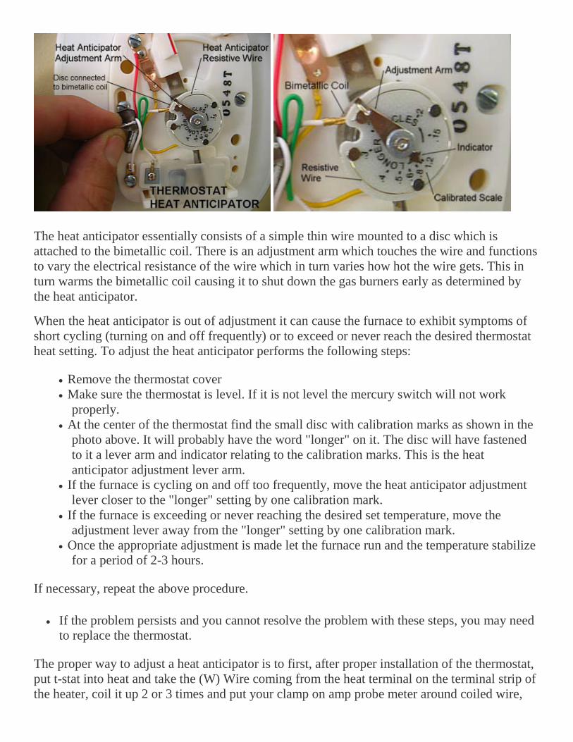
The heat anticipator essentially consists of a simple thin wire mounted to a disc which is attached to the bimetallic coil. There is an adjustment arm which touches the wire and functions to vary the electrical resistance of the wire which in turn varies how hot the wire gets. This in turn warms the bimetallic coil causing it to shut down the gas burners early as determined by the heat anticipator.
When the heat anticipator is out of adjustment it can cause the furnace to exhibit symptoms of short cycling (turning on and off frequently) or to exceed or never reach the desired thermostat heat setting. To adjust the heat anticipator performs the following steps:
• Remove the thermostat cover • Make sure the thermostat is level. If it is not level the mercury switch will not work
properly. • At the center of the thermostat find the small disc with calibration marks as shown in the
photo above. It will probably have the word "longer" on it. The disc will have fastened to it a lever arm and indicator relating to the calibration marks. This is the heat anticipator adjustment lever arm.
• If the furnace is cycling on and off too frequently, move the heat anticipator adjustment lever closer to the "longer" setting by one calibration mark.
• If the furnace is exceeding or never reaching the desired set temperature, move the adjustment lever away from the "longer" setting by one calibration mark.
• Once the appropriate adjustment is made let the furnace run and the temperature stabilize for a period of 2-3 hours.
If necessary, repeat the above procedure.
• If the problem persists and you cannot resolve the problem with these steps, you may need to replace the thermostat.
The proper way to adjust a heat anticipator is to first, after proper installation of the thermostat, put t-stat into heat and take the (W) Wire coming from the heat terminal on the terminal strip of the heater, coil it up 2 or 3 times and put your clamp on amp probe meter around coiled wire,
measure current. Then divide measured current draw into however many coils you put through the meter and whatever that number is the adjustment you need to make on the heat anticipator.
[Return to Q. # 10]
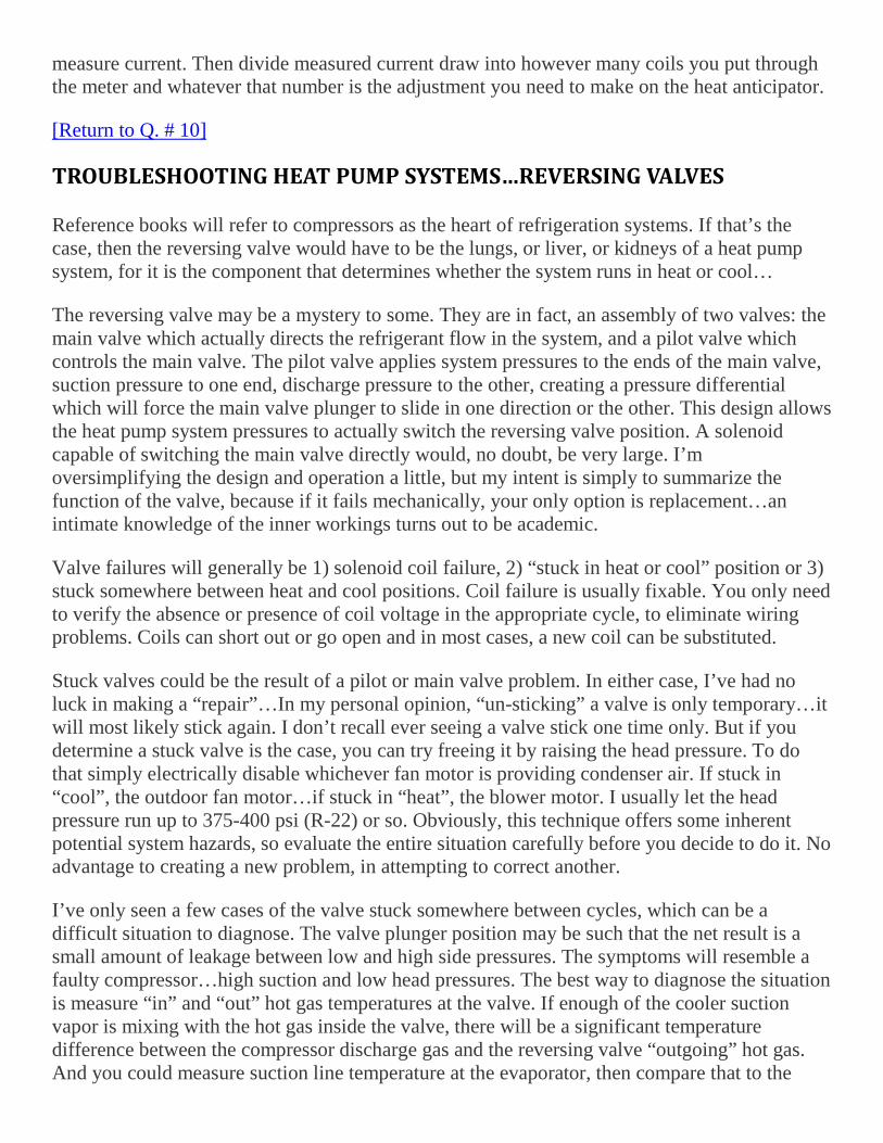
TROUBLESHOOTING HEAT PUMP SYSTEMS…REVERSING VALVES
Reference books will refer to compressors as the heart of refrigeration systems. If that’s the case, then the reversing valve would have to be the lungs, or liver, or kidneys of a heat pump system, for it is the component that determines whether the system runs in heat or cool…
The reversing valve may be a mystery to some. They are in fact, an assembly of two valves: the main valve which actually directs the refrigerant flow in the system, and a pilot valve which controls the main valve. The pilot valve applies system pressures to the ends of the main valve, suction pressure to one end, discharge pressure to the other, creating a pressure differential which will force the main valve plunger to slide in one direction or the other. This design allows the heat pump system pressures to actually switch the reversing valve position. A solenoid capable of switching the main valve directly would, no doubt, be very large. I’m oversimplifying the design and operation a little, but my intent is simply to summarize the function of the valve, because if it fails mechanically, your only option is replacement…an intimate knowledge of the inner workings turns out to be academic.
Valve failures will generally be 1) solenoid coil failure, 2) “stuck in heat or cool” position or 3) stuck somewhere between heat and cool positions. Coil failure is usually fixable. You only need to verify the absence or presence of coil voltage in the appropriate cycle, to eliminate wiring problems. Coils can short out or go open and in most cases, a new coil can be substituted.
Stuck valves could be the result of a pilot or main valve problem. In either case, I’ve had no luck in making a “repair”…In my personal opinion, “un-sticking” a valve is only temporary…it will most likely stick again. I don’t recall ever seeing a valve stick one time only. But if you determine a stuck valve is the case, you can try freeing it by raising the head pressure. To do that simply electrically disable whichever fan motor is providing condenser air. If stuck in “cool”, the outdoor fan motor…if stuck in “heat”, the blower motor. I usually let the head pressure run up to 375-400 psi (R-22) or so. Obviously, this technique offers some inherent potential system hazards, so evaluate the entire situation carefully before you decide to do it. No advantage to creating a new problem, in attempting to correct another.
I’ve only seen a few cases of the valve stuck somewhere between cycles, which can be a difficult situation to diagnose. The valve plunger position may be such that the net result is a small amount of leakage between low and high side pressures. The symptoms will resemble a faulty compressor…high suction and low head pressures. The best way to diagnose the situation is measure “in” and “out” hot gas temperatures at the valve. If enough of the cooler suction vapor is mixing with the hot gas inside the valve, there will be a significant temperature difference between the compressor discharge gas and the reversing valve “outgoing” hot gas. And you could measure suction line temperature at the evaporator, then compare that to the

“outlet” suction pressure tubing temperature at the valve body. What’s a normal temperature drop across the valve? It depends on where you measure of course, but from the few times I’ve actually checked, I’ll say 4 or 5 degrees max, with the higher differentials applying to the hot gas lines.
I’ve found reversing valves to be one of the more reliable components in heat pump systems. They generally perform their duties for many years, without failure. And when they do fail mechanically, it’s likely the result of some other system problem, such as continued operation with low charge, causing the valve to overheat and under lubricate…
Operating AC for Peak Efficiency
How to Operate AC for Peak Efficiency
Tip: Don't Use or Buy More Cooling Capacity Than You Need
Overcooling your home can be expensive and waste energy. Don't use or buy more cooling capacity than you actually need. Select an air conditioning unit with the lowest suitable capacity and highest efficiency. An oversized air conditioner can leave rooms cold and clammy because it does not run long enough to dehumidify the air. Oversized air conditioners also have a tendency to turn themselves on and off more frequently than properly sized units.
Tip: Keep the Equipment Clean
Ensure good air flow by keeping your condensing unit or heat pump free of debris. These pieces of equipment are located outdoors and require significant air flow to properly function. Clean the equipment at least once per year and regularly check to make sure leaves, grass and other debris are not creating blockage.
Tip: Change Your Air Filter Regularly
Changing your air filter regularly is a simple, inexpensive way to keep your air conditioning unit running at peak efficiency. The filter is located in your furnace, air handler or attached ducting. This filter helps keep dust and other debris from sticking to the blower and air conditioning coils inside your home's heat pump, air conditioner or furnace. A dirty filter can block the flow of air, increasing operating costs and damaging the equipment. Change your filter as often as recommended by the manufacturer.
Tip: Have the Indoor Coil Cleaned
The evaporator coil is located on the top or side of your furnace, and if you have an air handler, it is located inside the air handler. Air flows across the coil to be cooled during the summer. When the air conditioning is on, water collects on the coil. The moisture on the coil can attract dirt, mold and other contaminants. A dirty indoor coil can be unhealthy, wastes energy and cuts the capacity of the cooling equipment. The coil should be cleaned every two to three years. It
is sometimes necessary to cut into the ductwork to reach the coil, so it is advisable to hire a contractor to perform this maintenance for you.
Tip: Properly Match Your Condensing Unit/Heat Pump to Your Evaporator Coil
Your air-conditioning or heat pump system consists of two main parts: an indoor evaporator coil and an outdoor condensing unit/heat pump. These two parts are specifically designed to work together as a coordinated "team" to provide top performance and maximum efficiency and comfort. If you install a new high-efficiency condensing unit, but don't include a new, equally efficient and properly matched evaporator coil, you could end up with an inefficient or dysfunctional system.
Tip: Shade the Outside Condensing Unit or Heat Pump
Condensers and heat pumps that sit in a shady area use up to ten percent less electricity than those in direct sunlight.
Tip: Install a Programmable Thermostat
Programmable thermostats are recommended to help keep your energy bills low. You can program these thermostats to automatically change temperature settings at night or when you are not at home. Energy bills can be dramatically lowered by not running the air conditioner unnecessarily.
Tip: Set Your Thermostat at 78 Degrees During the Summer
Keep your energy bills low by setting your thermostat no lower than 78 degrees during the summer. You will still enjoy the comforts of air conditioning while not absorbing the high costs for energy consumption. For each degree below that economy setting, your energy bills will creep up by eight percent on average. That means, if you set the thermostat at 72 degrees, it's costing 48 percent more to run!
Tip: Install Ceiling Fans to Help Circulate Cool Air in the Home
The thermostat reads the temperature in your home, but what about the wind chill factor? Running a fan will help stir up the air in your home and make it feel 10 degrees cooler. Ceiling fans work the best when they run in a counter-clockwise direction. This causes them to blow air downward.
Tip: Check Your Ductwork
Sealing ductwork can help reduce energy consumption by 10 to 30 percent. Have a contractor inspect your ductwork for leaks. Pay extra attention to the ductwork that runs through the attic, basement or other un-cooled spaces in your home. Make sure the ductwork in these areas is properly insulated.
Tip: Keep Your Doors and Windows Shut and Well Sealed
Do-it-yourself weather stripping for doors and caulking for windows is cheap and easy to install. It pays to keep your house from leaking out cold air.
Tip: Don't Open Your Windows When the AC is Off
When we think of air conditioning, we think primarily of cooling. But a major comfort benefit besides cooling that air conditioning provides is dehumidification – removing moisture from the air. When the air is nice and dry in the summer, we feel comfortable. When the air is too humid, we feel clammy and uncomfortable. Removing moisture from the home’s air then is a major function of air conditioning.
Understanding how your air conditioner does this will help you to operate it for maximum efficiency and comfort. When you first decide to turn on your air conditioning and it is hot and humid, and the home’s windows are open, there is a lot of moisture (water) in the air. When you close the windows and turn on the central air conditioning, the air conditioner will use about ½ of its energy initially to remove that moisture from the air while it cools. Because there is so much water in the air to remove at the start, the air conditioner will take longer to cool the house down, with only half of its energy going towards cooling.
However, after the air conditioner runs for a few hours, the majority of the moisture will be removed. At this point, the air conditioner can cool much more quickly, as well as run for shorter times to maintain that cool temperature.
For best use then, keep your windows closed in between air conditioning usage if you think you will need to use the air conditioning again soon. For example, if at the end of the day you were thinking of opening the windows for the night, but will need to turn on the air conditioning again in the morning, you might want to keep the windows closed and the AC on at night, too. Keeping the home closed once it has been dehumidified will mean the air conditioning can use most of its energy to cool the home, which will make it work faster as well as save money on electrical usage. [Return to Q. # 27]
Return to top