Embed Size (px)
Citation preview

Research ArticleA Simple Attitude Control of Quadrotor Helicopter Based onZiegler-Nichols Rules for Tuning PD Parameters
ZeFang He1,2 and Long Zhao1,2
1 Science and Technology on Aircraft Control Laboratory, Beihang University, Beijing 100191, China2Digital Navigation Center, Beihang University, Beijing 100191, China
Correspondence should be addressed to Long Zhao; [email protected]
Received 25 August 2014; Accepted 10 October 2014; Published 29 December 2014
Academic Editor: Wenwu Yu
Copyright © 2014 Z. He and L. Zhao. This is an open access article distributed under the Creative Commons Attribution License,which permits unrestricted use, distribution, and reproduction in any medium, provided the original work is properly cited.
An attitude control strategy based on Ziegler-Nichols rules for tuning PD (proportional-derivative) parameters of quadrotorhelicopters is presented to solve the problem that quadrotor tends to be instable. This problem is caused by the narrow definitiondomain of attitude angles of quadrotor helicopters.The proposed controller is nonlinear and consists of a linear part and a nonlinearpart. The linear part is a PD controller with PD parameters tuned by Ziegler-Nichols rules and acts on the quadrotor decoupledlinear system after feedback linearization; the nonlinear part is a feedback linearization itemwhich converts a nonlinear system intoa linear system. It can be seen from the simulation results that the attitude controller proposed in this paper is highly robust, and itscontrol effect is better than the other two nonlinear controllers. The nonlinear parts of the other two nonlinear controllers are thesame as the attitude controller proposed in this paper. The linear part involves a PID (proportional-integral-derivative) controllerwith the PID controller parameters tuned by Ziegler-Nichols rules and a PD controller with the PD controller parameters tuned byGA (genetic algorithms). Moreover, this attitude controller is simple and easy to implement.
1. Introduction
Unmanned helicopters have been widely applied in militaryand commercial fields [1, 2]. Unmanned four-rotor heli-copters (quadrotor helicopters) are mostly used for searchand rescue, surveillance, reconnaissance, data acquisition,and so forth. Their potential applications include bor-der patrol, widefire monitoring, traffic monitoring, min-eral exploration, and transportation [3–5]. Compared toconventional helicopters, quadrotor helicopters show manyadvantages. Quadrotor helicopters have hovering and VTOL(vertical takeoff and landing) capabilities which are also thecharacteristic of conventional helicopters. In other words,they have large maneuverability, do not require large takeoffand landing site, and can execute special tasks in dangerousand inaccessible environments. Furthermore, conventionalhelicopters are structurally complex, expensive, and hardto control, while quadrotor helicopters are mechanicallysimple, demand low manufacturing and operational costs,
and are easy to control.Therefore, quadrotor helicopters drawintensive attention, and relevant technologies have also beenan important research topic in recent years [6]. Quadrotorhelicopter control is a challenging problem because a quadro-tor helicopter is a complex system with high nonlinearities,strong couplings, and underactuation [7]. Therefore, theresearch for the control system of quadrotor helicopters hasbeen widely conducted.
The methods for establishing a nonlinear model ofquadrotor helicopters include white box modeling, black boxmodeling, and grey box modeling. Grey box modeling iscommonly used in quadrotor modeling papers. The pro-cedure for modeling quadrotor by the grey box modelingmethod is as follows: firstly, system model is written withthe method of mechanismmodeling; secondly, because someof the parameters in the model are unknown, they need tobe derived by identification methods. There are two mainmechanism modeling methods: Newton-Euler formalismand Lagrange-Euler formalism. In [8], a nonlinear model
Hindawi Publishing Corporatione Scientific World JournalVolume 2014, Article ID 280180, 13 pageshttp://dx.doi.org/10.1155/2014/280180

2 The Scientific World Journal
was proposed by representing the quadrotor helicopterskinematics and dynamics characteristics based on Newton-Euler formalism. In [9], the same methodology was usedto obtain the motion equations and the rotor dynamicswere considered as well during the model establishment.The authors who established the quadrotor helicopters modelusing the Newton-Euler formalism in [9] described thequadrotor helicopters’ dynamics by the Lagrange-Euler for-malism in [10]. In this paper, quadrotor helicopter motionequations were obtained by the Newton-Euler formalismwithout considering the rotor dynamics during the modelestablishment.
The system equations were rewritten in state space forthe controller design. The quadrotor motion can be splitinto two motions: the angular rotation motion and thelinear translation motion. From the system equations, it canbe seen that the rotational motion is independent of thetranslational motion, while the translational motion dependson the rotational motion. The quadrotor control structure isusually divided into internal and external loops accordingto the characteristics of the system model. The former isused to control attitude and the latter to control position.According to the control strategy which internal and externalloop controls take, the quadrotor control can be dividedinto inner-outer loop control and full control. In inner-outer loop control methods, internal and external loops usedifferent control strategies while, in full control methods,the same control strategy is used by internal and externalloops. Different control methods which were recently testedon quadrotor helicopters are as follows: classic PID control[11], all kinds of improved methods of PID [6, 12], 𝐻
∞
control [4], predictive control [4], backstepping control [5,7, 9], sliding mode control [9], LQR control [10], dynamicsurface control [13], adaptive control [14, 15], neural net-work control [16], fuzzy control [17, 18], and the integratedmethod combined each other’s advantages such as integralsliding mode control [3], integral backstepping control [19],fuzzy integral sliding mode control based on backstepping[20], and robust adaptive control [21–23]. Despite that thedevelopment of control methods has experienced the clas-sical control, modern control, and intelligent control whichlargely improve the control effect, the classic PID controlis still the most common and practical one in engineeringcontroller design [24] because of its simplicity of controlprinciple. An important step in the PID controller designis to tune PID controller parameters. Engineers generallyuse empirical methods to derive adjustable parameter, butit is time-consuming and thus inefficient. As such, a varietyof intelligent PID parameter tuning methods have beenproposed and studied in the literature. However, as withintelligent control methods, the parameter tuning methodsare too complicated to be mastered by engineering techni-cians despite the good effect. The Ziegler-Nichols rules fortuning the PID controller, which were proposed by Zieglerand Nichols in 1942, have been widely recognized and usedas described in [25] because it is simple and practical. Inaddition, the feedback linearizationmethod [26] is also a verygood method to decouple and linearize quadrotor models.In view of the advantages of the Ziegler-Nichols rules for
T1
Ω1
T2
Ω2
T3
Ω3
T4
Ω4
x
yB
z
r
EE
N
D
Figure 1: The structure of a quadrotor helicopter.
tuning the PID controller and the feedback linearizationmethod, the quadrotor attitude control strategy adopted inthis paper is depicted as follows. The PD controller tunedby Ziegler-Nichols rules is firstly applied to the linearizedmodel of quadrotor after the feedback linearization. Further,the nonlinear controller consisting of the PD control andfeedback linearization item is applied to the quadrotorcontrolled object. The PD controller with PD parameterstuned by Ziegler-Nichols rules is first applied to quadrotorHelicopter in this paper.
The remainder of the paper is organized as follows:the quadrotor helicopter model is described in Section 2.The control strategy is proposed in Section 3. In Section 4,the controller design principle is presented and containsfeedback linearization, Ziegler-Nichols ruler for adjustingparameters, the controller parameter choice, and final form.Simulation results are reported in Section 5. Finally, themajorconclusions of the paper are exposed in Section 6.
2. Quadrotor Model
A quadrotor helicopter uses four rotors as the direct powerof flight. Four rotors with the same structure and radius aresymmetrically located on the four edges of a cross formed bytwo arms and located on a plane at the same height. Rotor1 and rotor 3 rotate in the counterclockwise direction androtor 2 and rotor 4 rotate in the clockwise direction. Fourmotors were symmetrically installed on the stent ends of thequadrotor; flight control computer and external equipmentwere installed in the space of the stent middle. The structureof a quadrotor helicopter is shown in Figure 1, where 𝐵
represents the body coordinate system and 𝐺 represents theground coordinate system.
The attitude and location of a quadrotor helicopter canbe controlled to desired values by changing four motorspeeds (which results in the changes of four rotor speedsand corresponding lift). The following several kinds of forceand moment can be performed on the quadrotor helicopter:the lifts caused by rotors rotation, the pitching moment androllingmoment caused by the difference of four rotors lift, the

The Scientific World Journal 3
gravity, the gyroscopic effect, and aerodynamic torque effect,that is, yawing moment. The gyroscopic effect only appearsin the lightweight construction quadrotor helicopter. Yawingmoment is caused by unbalanced four rotors rotationalspeeds. The gyroscopic effect and yawing moment are inessence caused by the reaction torques. The reaction torquesare caused by the rotor rotation; its direction is exactlyopposite of the rotor rotation direction. Yaw moment can becancelled when two rotors rotate in the opposite direction.The gyroscopic effect and aerodynamic torque effect are offsetwhen the quadrotor hovers.
The space motion of the rigid body aircraft can bedivided into two parts: the centre of mass movement andmovement around the centre of mass. Six degrees of freedomare required in describing any time space motion. Theyare three barycenter movements and three angular motions,namely, three translation and three rotation motions alongthree axes. The control for six degrees of freedom motionscan be implemented by adjusting the rotational speeds of dif-ferent motors. Basic motions include forward and backwardmovements, lateral movement, vertical motion, roll motion,and pitch and yawmotions.The yawmotion of the quadrotorhelicopter can be realised by a reactive torque producedby the rotor. The size of the reactive torque is relative tothe rotor speed. When the four rotor speeds are the same,the reactive torques will offset by each other and quadrotorwill remain still, whereas if the four rotor speeds are notabsolutely same, the reactive torques will not be absolutelyoffset, and the quadrotor will start to rotate. The rotation ofthe quadrotor should be eliminated during the other motionsof the quadrotor to ensure the stability of motions. That thefour rotor speeds synchronously increase and decrease isalso required in the vertical movement. When the quadrotorhelicopter flies in the pitch and roll motion mode, horizontalmotion along 𝑥- and 𝑦-axes will be triggered. In order toobtain the subduction motion and forward movement, thespeed of the rear rotor must be increased and the speed ofthe front rotor must be decreased; on the contrary, nose-uppitch movement and backward movement can be produced.Similarly, the roll movement and lateral movement can beobtained by controlling the left rotor and right rotor.
Because of four inputs and six state outputs in a quadro-tor, the quadrotor is considered an underactuated complexsystem. In order to control it, some assumptions are made inthe process of quadrotor modeling as follows: quadrotor is arigid body; the structure is symmetric; the centre of gravityand the origin of body coordinate system are coincident andground effect is ignored.
The causes of the lift, gravity, and aerodynamic torqueacting on a quadrotor differ from each other. Thus, it isvery important to choose the appropriate coordinate systemto exactly describe the quadrotor space motion state. Forexample, it is more convenient to describe the gravity of theaircraft in the ground coordinate frame and to describe the liftacting on the quadrotor; the body coordinate frame is moresuitable. Therefore, when establishing a quadrotor motionmodel, reasonably choosing different coordinate frames isone of the important links to define and describe variousmotion parameters of the quadrotor.
Given an aircraft, the positive 𝑥 direction in the bodycoordinate frame is usually defined as the moving direction,the positive 𝑦 direction as the right side of the movingdirection, and the positive 𝑧 direction as the vertical down-ward direction; this is also termed forward-right-downwardcoordinate frame [26].
Because the fly altitude of quadrotor helicopters is limitedin the atmosphere, the “flat earth hypothesis” can be adoptedto consider the ground coordinate frame as an inertialcoordinate frame to simplify the modeling complexity. Inorder to facilitate navigation and way-point tracking, theaxis directions of the ground coordinate frame are chosenas north-east-down navigation frame directions, namely, thatthe 𝑋
𝑔axis points to the north, the 𝑌
𝑔axis points to the east,
and the 𝑍𝑔axis is perpendicular to the ground and points to
the center of the earth.The procedure of the Newton-Euler formalism modeling
is to project lift forces acting on the aircraft to the groundcoordinate frame and analyze the linearmotion of the aircraftwith Newton’s second law in the inertial coordinate systemand the angularmotion of the aircraftwith the law ofmomentof momentum in the body coordinate system.
2.1. Kinematics Model. The transformation matrix betweentwo rectangular coordinate systems is orthogonal. 𝑅(𝑥, 𝜙),𝑅(𝑦, 𝜃), and𝑅(𝑧, 𝜓) denote rotationmatrices produced by theground coordinate frame rotating roll angle 𝜙, pitch angle 𝜃,and yaw angle 𝜓 around 𝑥-, 𝑦-, and 𝑧-axes, respectively, andthe expressions are as follows:
𝑅 (𝑥, 𝜙) = [
[
1 0 0
0 cos𝜙 sin𝜙
0 − sin𝜙 cos𝜙]
]
,
𝑅 (𝑦, 𝜃) = [
[
cos 𝜃 0 − sin 𝜃
0 1 0
sin 𝜃 0 cos 𝜃]
]
,
𝑅 (𝑧, 𝜓) = [
[
cos𝜓 sin𝜓 0
− sin𝜓 cos𝜓 0
0 0 1
]
]
.
(1)
The rotation matrix from the ground coordinate systemto the body coordinate system is the product of formulae (1),which denote rotation around the 𝑧-axis followed by rotationaround 𝑦-axis and finally followed by rotation around 𝑥-axis;namely,
𝑅𝐸→𝐵
= 𝑅 (𝑥, 𝜙) 𝑅 (𝑦, 𝜃) 𝑅 (𝑧, 𝜓) . (2)
Therefore, the transformation matrix from the ground coor-dinate system to the body coordinate system is given by
𝑅𝐵→𝐸
= 𝑅𝑇
𝐸→𝐵. (3)

4 The Scientific World Journal
𝜃
𝜃
𝜙
𝜙
p
x
yqr
𝜓
𝜓
𝜃𝜙
𝜓
Xg
Yg
Zg
z
Figure 2: The relationships between angular velocity componentsand the attitude angle change rate.
The specific expression is given by
𝑅𝐵→𝐸
= [
[
𝑐𝜃𝑐𝜓
𝑠𝜙𝑠𝜃𝑐𝜓− 𝑐𝜙𝑠𝜓
𝑐𝜙𝑠𝜃𝑐𝜓+ 𝑠𝜙𝑠𝜓
𝑐𝜃𝑠𝜓
𝑠𝜙𝑠𝜃𝑠𝜓+ 𝑐𝜙𝑐𝜓
𝑐𝜙𝑠𝜃𝑠𝜓− 𝑠𝜙𝑐𝜓
−𝑠𝜃
𝑠𝜙𝑐𝜃
𝑐𝜙𝑐𝜃
]
]
, (4)
where 𝑐⋅= cos(⋅) and 𝑠
⋅= sin(⋅).
The angular velocity components 𝑝, 𝑞, and 𝑟 are theprojection values on the body coordinate system of rotationangular velocity 𝜔 which denotes the rotation from theground coordinate system to the body coordinate system.Therelationships between angular velocity components and theattitude angle change rates are shown in Figure 2.
The transformation matrix from [ 𝜙 𝜃 ��]𝑇 to [𝑝 𝑞 𝑟]
𝑇
is given by
[
[
𝑝
𝑞
𝑟
]
]
= 𝑅𝑟
[
[
𝜙
𝜃
��
]
]
, (5)
where
𝑅𝑟= [
[
1 0 − sin 𝜃
0 cos𝜙 sin𝜙 cos 𝜃0 − sin𝜙 cos𝜙 cos 𝜃
]
]
. (6)
Around hovering position, 𝑅𝑟is assumed as a unit matrix
[26].
2.2. DynamicModel. Thedynamicsmodel is composed of therotational and translational motions. The rotational motionis fully actuated, while the translational motion is underactu-ated. In the body coordinate system, the rotational motionequations are derived according to the law of momentumtheorem and gyroscopic effect of quadrotor, and they aregiven by
𝐽�� + 𝜔 × 𝐽𝜔 + 𝜔 × [0 0 𝐽𝑟Ω𝑟] = 𝑀
𝐵, (7)
where 𝐽 is the inertia matrix of quadrotor which is diagonalunder the hypothesis of structure symmetry and the elements𝐼𝑥, 𝐼𝑦, and 𝐼
𝑧are, respectively, inertia matrices of 𝑥-, 𝑦-,
and 𝑧-axes. The last item on the left side of (7) representsthe gyroscopic effect which is caused by the inertia of therotors 𝐽
𝑟and relative speed Ω
𝑟= −Ω
1+ Ω2
− Ω3
+ Ω4,
where Ω𝑖(𝑖 = 1, 2, 3, 4) represents the 𝑖th rotor speed. The
aerodynamic force and moment produced by the 𝑖th rotorare directly proportional to the square of the rotor speed.Therelationships are given by
𝐹𝑖= 𝑏Ω2
𝑖,
𝑀𝑖= 𝑑Ω2
𝑖,
(8)
where 𝑏 and 𝑑 are the aerodynamic force and momentconstants, respectively.Themoments acting on the quadrotorin the body coordinate system are given by
𝑀𝐵
=[[
[
𝑙 ⋅ 𝑏 (−Ω2
2+ Ω2
4)
𝑙 ⋅ 𝑏 (Ω2
1− Ω2
3)
𝑑 (Ω2
1− Ω2
2+ Ω2
3− Ω2
4)
]]
]
, (9)
where 𝑙 is the moment arm which represents the distancefrom the axis of a rotor to the center of quadrotor.
The translational motion equations are obtained in theground coordinate system by the method of Newton’s secondlaw:
𝑚 𝑟 = [0 0 𝑚𝑔]𝑇
+ 𝑅𝐹𝐵, (10)
where 𝑟 = [𝑥 𝑦 𝑧]𝑇 is the position of quadrotor in the
ground coordinate system, 𝑚 is the mass of quadrotor, 𝑔 isthe acceleration of gravity, and 𝐹
𝐵is the total lift force acting
on quadrotor in the body coordinate system; namely,
𝐹𝐵
= [
[
0
0
−𝑏 (Ω2
1+ Ω2
2+ Ω2
3+ Ω2
4)
]
]
. (11)
2.3. The Motion Equations of Quadrotor. Synthesizing thekinematics and dynamics models of quadrotor, the motionequations of quadrotor can be derived as follows:
𝜙 = 𝜃�� (
𝐼𝑦− 𝐼𝑧
𝐼𝑥
) −𝐽𝑟
𝐼𝑥
𝜃Ω𝑟+
𝐿
𝐼𝑥
𝑈2,
𝜃 = 𝜙�� (𝐼𝑧− 𝐼𝑥
𝐼𝑦
) +𝐽𝑟
𝐼𝑦
𝜙Ω𝑟+
𝐿
𝐼𝑦
𝑈3,
�� = 𝜙 𝜃 (
𝐼𝑥− 𝐼𝑦
𝐼𝑧
) +1
𝐼𝑧
𝑈4,
�� = −𝑈1
𝑚(cos𝜙 sin 𝜃 cos𝜓 + sin𝜙 sin𝜓) ,
𝑦 = −𝑈1
𝑚(cos𝜙 sin 𝜃 sin𝜓 − sin𝜙 cos𝜓) ,
�� = 𝑔 −𝑈1
𝑚(cos𝜙 cos 𝜃) ,
(12)

The Scientific World Journal 5
where 𝑈1, 𝑈2, 𝑈3, and 𝑈
4are the control input variables,
which can be calculated by𝑈1= 𝑏(Ω
2
1+ Ω2
2+ Ω2
3+ Ω2
4),𝑈2=
𝑏(−Ω2
2+Ω2
4),𝑈3= 𝑏(Ω
2
1−Ω2
3), and𝑈
4= 𝑑(Ω
2
1−Ω2
2+Ω2
3−Ω2
4),
respectively.
3. Control Strategy
The state space model adopted by the control system is�� = 𝑓(𝑋,𝑈), where 𝑋 is the state vector and 𝑈 is thecontrol input vector. The state vector is chosen as 𝑋 =
[𝑥 𝑦 𝑧 �� 𝑦 �� 𝜙 𝜃 𝜓 𝜙 𝜃 ��]𝑇. In the design of con-
troller, the state variables are chosen as𝑥1= 𝑥,𝑥
2= 𝑦,𝑥
3= 𝑧,
𝑥4
= ��1
= ��, 𝑥5
= ��2
= 𝑦, 𝑥6
= ��3
= ��, 𝑥7
= 𝜙, 𝑥8
= 𝜃,𝑥9= 𝜓, 𝑥
10= ��7= 𝜙, 𝑥
11= ��8= 𝜃, and 𝑥
12= ��9= ��.
Synthesizing the motion equations of quadrotor, the statevector, and the control input variables, the state equations canbe described as
𝑓 (𝑋,𝑈) =
[[[[[[[[[[[[[[[[[[[[[[[[[[[[[[[[[[[
[
𝑥4
𝑥5
𝑥6
−𝑈1
𝑚(cos𝑥
7sin𝑥8cos𝑥9+ sin𝑥
7sin𝑥9)
−𝑈1
𝑚(cos𝑥
7sin𝑥8sin𝑥9− sin𝑥
7cos𝑥9)
𝑔 −𝑈1
𝑚(cos𝑥
7cos𝑥8)
𝑥10
𝑥11
𝑥12
𝑥11𝑥12
𝐼𝑦− 𝐼𝑧
𝐼𝑥
−𝐽𝑟
𝐼𝑥
𝑥11Ω𝑟+
𝐿
𝐼𝑥
𝑈2
𝑥10𝑥12
𝐼𝑧− 𝐼𝑥
𝐼𝑦
+𝐽𝑟
𝐼𝑦
𝑥10Ω𝑟+
𝐿
𝐼𝑦
𝑈3
𝑥10𝑥11
𝐼𝑥− 𝐼𝑦
𝐼𝑧
+1
𝐼𝑧
𝑈4
]]]]]]]]]]]]]]]]]]]]]]]]]]]]]]]]]]]
]
.
(13)
It can be seen from (13) that the rotation motions areindependent of translational movements and full actuated,while translational motions are underactuated and dependon the rotation motions. Therefore, a control structure withinner and outer loops is designed in which the inner controlloop is designed to ensure asymptotic tracking for the desiredattitude and altitude and the outer loop is designed tonavigate. The structure diagram is shown in Figure 3. Asstabilizing attitude is the basis of controlling the quadrotor,quadrotor attitude controller is designed in this paper. Inthis paper, attitude control strategy of the quadrotor is firstlyapplying PD controller tuned by Ziegler-Nichols rules to thelinear model of quadrotor after feedback linearization andthen nonlinear controller consisting of the PD control andfeedback linearization item acts on the quadrotor controlledobject.
Desiredposition
Positioncontroller
Roto
rs sp
eed
calc
ulat
ionxd
yd
Attitudecontroller
Altitudecontroller
Headingcontroller
Desiredposition
𝜑d
𝜃d
𝜃𝜑
𝜓d
zd U1
U2
U3
U4
Ω1→4
z
x y
Figure 3: Quadrotor control structure.
To design attitude controller, the rotation motion equa-tions are separately extracted and simplified, and they aregiven by
��10
= 𝑎1𝑥11𝑥12
− 𝑎2𝑥11Ω𝑟+ 𝑏1𝑈2,
��11
= 𝑎3𝑥10𝑥12
+ 𝑎4𝑥10Ω𝑟+ 𝑏2𝑈3,
��12
= 𝑎5𝑥10𝑥11
+ 𝑏3𝑈4,
(14)
where 𝑎1= (𝐼𝑦−𝐼𝑧)/𝐼𝑥, 𝑎2= 𝐽𝑟/𝐼𝑥, 𝑎3= (𝐼𝑧−𝐼𝑥)/𝐼𝑦, 𝑎4= 𝐽𝑟/𝐼𝑦,
𝑎5= (𝐼𝑥− 𝐼𝑦)/𝐼𝑧, 𝑏1= 𝐿/𝐼𝑥, 𝑏2= 𝐿/𝐼𝑦, and 𝑏
3= 1/𝐼𝑧.
4. Controller Design Principle
4.1. Feedback Linearization Theory. The smaller the rotorinertia of quadrotor is, the smaller the impact of gyroscopiceffect is. Therefore, during the design of attitude controller,the simplified rotation motion equations are derived byignoring the influence of the gyroscopic effect item as
��10
= 𝑎1𝑥11𝑥12
+ 𝑏1𝑈2,
��11
= 𝑎3𝑥10𝑥12
+ 𝑏2𝑈3,
��12
= 𝑎5𝑥10𝑥11
+ 𝑏3𝑈4.
(15)
In order to obtain a linear model to make further controleasily realize, in this paper, a feedback linearization techniqueis adopted to linearize a nonlinear system.The control inputs𝑈2, 𝑈3, and 𝑈
4are chosen as
𝑈2= 𝑓2(𝑥10, 𝑥11, 𝑥12) + 𝑈
#2,
𝑈3= 𝑓3(𝑥10, 𝑥11, 𝑥12) + 𝑈
#3,
𝑈4= 𝑓4(𝑥10, 𝑥11, 𝑥12) + 𝑈
#4,
(16)
where 𝑈#2, 𝑈#3, and 𝑈
#4are new inputs. On this basis, in order
to obtain a linearmodel, the following equations still demandto be met:
𝑎1𝑥11𝑥12
+ 𝑏1𝑓2(𝑥10, 𝑥11, 𝑥12) = 𝐾
2𝑥10,
𝑎3𝑥10𝑥12
+ 𝑏2𝑓3(𝑥10, 𝑥11, 𝑥12) = 𝐾
3𝑥11,
𝑎5𝑥10𝑥11
+ 𝑏3𝑓4(𝑥10, 𝑥11, 𝑥12) = 𝐾
4𝑥10,
(17)

6 The Scientific World Journal
where𝐾2,𝐾3, and𝐾
4are undetermined parameters. Accord-
ing to (17), the feedback linearization items𝑓2, 𝑓3, and 𝑓
4are
given as
𝑓2(𝑥10, 𝑥11, 𝑥12) =
1
𝑏1
(𝐾2𝑥10
− 𝑎1𝑥11𝑥12) ,
𝑓3(𝑥10, 𝑥11, 𝑥12) =
1
𝑏2
(𝐾3𝑥11
− 𝑎3𝑥10𝑥12) ,
𝑓4(𝑥10, 𝑥11, 𝑥12) =
1
𝑏3
(𝐾4𝑥10
− 𝑎5𝑥10𝑥11) .
(18)
Similarly, if considering gyroscopic effect, feedback lin-earization items𝑓
2, 𝑓3, and 𝑓
4are derived as
𝑓2(𝑥10, 𝑥11, 𝑥12) =
1
𝑏1
(𝐾2𝑥10
+ 𝑎2𝑥11Ω𝑟− 𝑎1𝑥11𝑥12) ,
𝑓3(𝑥10, 𝑥11, 𝑥12) =
1
𝑏2
(𝐾3𝑥11
− 𝑎4𝑥10Ω𝑟− 𝑎3𝑥10𝑥12) ,
𝑓4(𝑥10, 𝑥11, 𝑥12) =
1
𝑏3
(𝐾4𝑥10
− 𝑎5𝑥10𝑥11) .
(19)
Substituting (16) into (15), meanwhile considering (17), thelinear system can be obtained as
��10
= 𝐾2𝑥10
+ 𝑏1𝑈
#2,
��11
= 𝐾3𝑥11
+ 𝑏2𝑈
#3,
��12
= 𝐾4𝑥12
+ 𝑏3𝑈
#4.
(20)
It can be seen from (20) that the corresponding linearclosed-loop system is still stable even considering the gyro-scopic effect. In order to prove the stability of the closed-loopsystem, in this paper, under the condition of𝑈#
2= 𝑈
#3= 𝑈
#4=
0 and operating points 𝑥10
= 𝑥11
= 𝑥12
= 0, we consider theLyapunov function
𝑉 (𝑥10, 𝑥11, 𝑥12) = 0.5 (𝑥
2
10+ 𝑥2
11+ 𝑥2
12) . (21)
Equation (21) is an attitude controller, and it is positivedefinite near the operating point. The first derivative of theLyapunov function can be derived using (14) which is amodelexpression including gyroscopic effect item, (16) and (19);meanwhile, it can be derived using (15) which is a simplifiedmodel expression, (16) and (18). It can be seen that the abovetwo first derivatives of the two Lyapunov functions are thesame, which denotes the affair that the model includinggyroscopic effect item will not affect the stability of thesystem. The first derivative of Lyapunov function is given by
�� = 𝑥10��10
+ 𝑥11��11
+ 𝑥12��12
= 𝐾2𝑥2
10+ 𝐾3𝑥2
11+ 𝐾4𝑥2
12.
(22)
The derivative expressed by (22) is negative definite if𝐾2
< 0, 𝐾3
< 0, and 𝐾4
< 0, which guarantees thatthe operating point of the feedback linearization system isasymptotically stable.
Considering ��7
= 𝑥10, ��8
= 𝑥11, and ��
9= 𝑥12, it is
obvious that the feedback linearization system, that is, (20),can be described by linear decoupled differential equationsof second order; namely,
��7= 𝐾2��7+ 𝑏1𝑈
#2,
��8= 𝐾3��8+ 𝑏2𝑈
#3,
��9= 𝐾4��9+ 𝑏3𝑈
#4.
(23)
The Laplace transformation is applied to (23), whichcan transform the system from time domain to frequencydomain. Further, the open-loop transfer functions of con-trolled object quadrotor can be obtained as
𝐺1(𝑠) =
𝑋7(𝑠)
𝑈#2(𝑠)
=𝑏1
𝑠2 − 𝐾2𝑠,
𝐺2(𝑠) =
𝑋8(𝑠)
𝑈#3(𝑠)
=𝑏2
𝑠2 − 𝐾3𝑠,
𝐺3(𝑠) =
𝑋9(𝑠)
𝑈#4(𝑠)
=𝑏3
𝑠2 − 𝐾4𝑠,
(24)
where the system is minimum phase system only when 𝐾2<
0, 𝐾3< 0, and 𝐾
4< 0.
4.2. Ziegler-Nichols PD Parameter Setting Principles. Aimingat the decoupled linear controlled object shown in (23), asimple and practical PD controller is designed.The controllerparameters proportion and derivative coefficients are the cor-responding proportion and derivative coefficients among thePID parameters adjusted by Ziegler-Nichols PID parameterssetting rules. Ziegler-Nichols method is a PID parametersetting method based on stability analysis. The setting of themethod for proportion coefficient 𝐾
𝑃is, firstly, fixing 𝐾
𝐷=
𝐾𝐼
= 0; secondly, increasing 𝐾𝑃until the system begins
to shock when the closed-loop system poles are on the 𝑗𝑤
axis; finally, multiplying𝐾𝑃by 0.6.The final𝐾
𝑃is proportion
coefficient after setting. Setting formula is given by
𝐾𝑃
= 0.6𝐾𝑚,
𝐾𝐷
=𝐾𝑃𝜋
4𝜔𝑚
,
𝐾𝐼=
𝐾𝑃𝜔𝑚
𝜋,
(25)
where𝐾𝑚is𝐾𝑃value derivedwhen the systembegan to shock
and 𝜔𝑚is the frequency of oscillation. 𝐾
𝑚and 𝜔
𝑚can be
determined using the root locus method. For a given transferfunction of the controlled object, one can get its root locus.𝐾𝑚
is the gain traversing the 𝑗𝑤 axis, and the oscillationfrequency of the point corresponds to 𝜔
𝑚.
4.3. Controller Final Form and Parameter Choice. Theexpres-sions of linear controllers𝑈#
2,𝑈#3, and𝑈
#4can be written after
obtaining the PID parameter value. Further, the expressions

The Scientific World Journal 7
of nonlinear controllers 𝑈2, 𝑈3, and 𝑈
4also can be written.
The actual control loop is discrete time system with samplingperiod 𝑇
𝑠. Therefore, in MATLAB simulation, the discrete
PID control applies in continuous system [27]. In thispaper, a series of sampling points 𝐾𝑇
𝑠is selected to replace
continuous time 𝑡, the integral is approximately replaced byrectangle method numerical integral, and the differential isapproximately replaced by first-order backward difference;namely,
𝑡 ≈ 𝑘𝑇 (𝑘 = 0, 1, 2, . . .) ,
∫
𝑡
0
error (𝑡) 𝑑𝑡 ≈ 𝑇
𝑘
∑
𝑗=0
error (𝑗𝑇) = 𝑇
𝑘
∑
𝑗=0
error (𝑗) ,
𝑑error (𝑡)𝑑𝑡
≈error (𝑘𝑇) − error ((𝑘 − 1) 𝑇)
𝑇
=error (𝑘) − error (𝑘 − 1)
𝑇.
(26)
The resulting PD controllers 𝑈#2, 𝑈#3, and 𝑈
#4are given by
𝑈#2(𝑘) = 𝐾
𝑃2err 2 (𝑘) + 𝐾
𝐷2
err 2 (𝑘) − err 2 (𝑘 − 1)
𝑇𝑠
,
𝑈#3(𝑘) = 𝐾
𝑃3err 3 (𝑘) + 𝐾
𝐷3
err 3 (𝑘) − err 3 (𝑘 − 1)
𝑇𝑠
,
𝑈#4(𝑘) = 𝐾
𝑃4err 4 (𝑘) + 𝐾
𝐷4
err 4 (𝑘) − err 4 (𝑘 − 1)
𝑇𝑠
,
(27)
where the subscript 2 represents the roll angle loop, thesubscript 3 represents the pitch angel loop, the subscript 4represents yaw angle loop, and err 2(𝑘), err 3(𝑘), and err 4(𝑘)represent the differences between the expected values and theactual values of the roll, pitch, and yaw angles, respectively.
Substituting (18) and (27) into (16) and sorting, nonlinearcontrollers 𝑈
2, 𝑈3, and 𝑈
4are derived as
𝑈2(𝑘) =
1
𝑏1
(𝐾2𝑥10
− 𝑎1𝑥11𝑥12) + 𝐾𝑃2err 2 (𝑘)
+ 𝐾𝐷2
err 2 (𝑘) − err 2 (𝑘 − 1)
𝑇𝑠
,
𝑈3(𝑘) =
1
𝑏2
(𝐾3𝑥11
− 𝑎3𝑥10𝑥12) + 𝐾𝑃3err 3 (𝑘)
+ 𝐾𝐷3
err 3 (𝑘) − err 3 (𝑘 − 1)
𝑇𝑠
,
𝑈4(𝑘) =
1
𝑏3
(𝐾4𝑥12
− 𝑎5𝑥10𝑥11) + 𝐾𝑃4err 4 (𝑘)
+ 𝐾𝐷4
err 4 (𝑘) − err 4 (𝑘 − 1)
𝑇𝑠
,
(28)
where 𝐾2, 𝐾3, and 𝐾
4are the optimal values obtained by
using a single optimizationmethod.The goal of optimizationprocess is to stabilize systemperformance and tomake system
have faster response and smaller overshoot amount as muchas possible. The PID controller parameters are adjusted byZiegler-Nichols principles.
5. Simulation Results
In order to test the control effect of the nonlinear controllerproposed in this paper, the simulation experiment wascarried out. Single control and joint control for a quadrotorwere carried out, respectively. Meanwhile, the control effectcomparison was done among the three nonlinear controllerswhich have the same feedback linearization item and thedifferent linear control parts. The linear part of the con-troller adopted in this paper is a PD controller with PDparameters tuned by Ziegler-Nichols rules, while the linearparts of the other two nonlinear controllers are, respectively,PID controller with the PID controller parameters tunedby Ziegler-Nichols rules and PD controller with the PDcontroller parameters tuned by GA.The other two nonlinearcontrollers are also proposed in this paper and are used toapprove the advantages of ZN-PD controller adopted in thispaper. Besides, the system robust performance test was doneunder the condition of noise interference. In this paper, thesingle control is defined as controlling one of the quadrotor’sattitude angles from zero initial state to the desired angle,for example, controlling pitch angle to the desired angle,while the other two attitude angles roll and yaw anglesare still located in the initial state; joint control is definedas controlling all of the quadrotor’s attitude angles to theexpectation, namely, simultaneously controlling roll, pitch,and yaw angles to the desired angles. In this paper, we testrobust performance of this system only with the interferenceof zero-mean white noise. The quadrotor parameters used inthis paper are as follows: 𝑚 = 0.4794 kg, 𝑔 = 9.81m/s2,𝑙 = 0.225m, 𝐼
𝑥= 𝐼𝑦
= 0.0086 kg⋅m2, 𝐼𝑧
= 0.0172 kg⋅m2,𝐽rotor = 3.7404 × 10
−5, 𝑏 = 3.13 × 10⁻⁵, 𝑑 = 9 × 10
−7,𝐾2= −14.6211, 𝐾
3= −14.6211, 𝐾
4= −32, and 𝑈
1= 𝑚 ∗ 𝑔.
The transfer function for the roll angle loop after feed-back linearization is 𝐺
1(𝑠) = 𝑋
7(𝑠)/𝑈
#2(𝑠) = 𝑏
1/(𝑠2
−
𝐾2𝑠) = 26.1628/(𝑠
2
+14.6211𝑠).The target value optimizationdiagram using GA to tune PID parameter values of thisattitude loop is shown in Figure 4. The ultimate values andinitial values scope of PID parameters in GA parameteroptimization are shown in Table 1.
The PID parameter modulation processes for pitch angleand yaw angle loops are similar to themodulation process forroll angle loop. Just different initial values of PID parametersare applied to pitch angle and yaw angle loops. The PIDparameter values tuned by Ziegler-Nichols rules and GA areshown in Table 2.The positive and negative 20 percent of PIDparameters for each attitude loop tuned by Ziegler-Nicholsrules are chosen as the initial values of PID parameters forGA optimization.
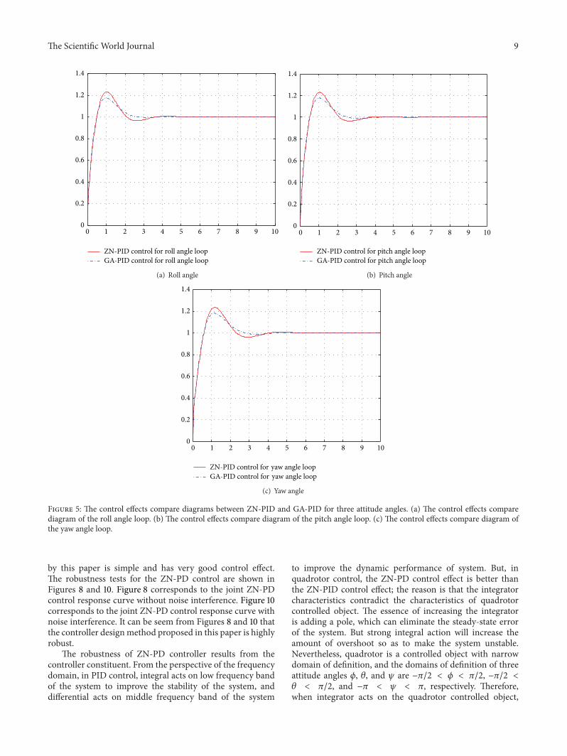
The control effects compare diagrams between ZN-PID(PID control with PID parameters tuned by Ziegler-Nicholsrules) and GA-PID (PID control with PID parameters tunedby GA) for three attitude angle loops which are shown inFigure 5. It can be seen from Figure 5, for three attitude angle

8 The Scientific World Journal
Table 1: The ultimate values and initial values scope of PID parameters in GA parameter optimization.
𝑃 𝐼 𝐷
The ultimate PID parameter values 2.2310 2.9996 0.1969The initial value scopes of PID parameters [1.49344, 2.24016] [2.97896, 4.46844] [0.1872, 0.2808]
Table 2: PID parameter values tuned by Ziegler-Nichols rules and GA.
AttitudePID value
PID parameter values tuned by Ziegler-Nichols rules PID parameter values tuned by GA𝑃 𝐼 𝐷 𝑃 𝐼 𝐷
Roll angle 1.8668 3.7237 0.2340 2.2310 2.9996 0.1969Pitch angle 1.8572 3.6941 0.2334 2.1756 3.0239 0.2022Yaw angle 1.5064 3.0067 0.1887 1.8013 2.479 0.1528
0 10 20 30 40 50 60 70 80 90 100286
287
288
289
290
291
292
293
294
t (s)
Best J
Figure 4: The target value optimization diagram using GA to tunePID parameter values of roll angle loop.
loops, the control effects of GA-PID are all better than thoseof ZN-PID.
The following ZN-PD control (PD control with PDparameters tuned by Ziegler-Nichols rules), GA-PD control(PD control with PD parameters tuned by GA), and ZN-PIDcontrol (PID control with PID parameters tuned by Ziegler-Nichols rules), respectively, stand for the linear controlparts of three attitude controllers appearing in this paper.GA-PD control and ZN-PID control are used to comparecontrol effect with ZN-PD control adopted in this paper. Thenonlinear parts of three attitude controllers are the same.For convenience, the names of the linear control parts ofthree different kinds of nonlinear controllers, respectively,represent the corresponding nonlinear controllers.
The control response comparison diagrams of the singleZN-PD control and the single GA-PD are shown in Figure 6.It can be seen from Figure 6 that ZN-PD control and GA-PD control can control three attitude angles to any valuein their domain of definition; for the roll and pitch angleloops, the control effects of GA-PD are better than the one
of ZN-PD; for the yaw angle loop, GA-PD control has alarge overshoot while ZN-PD quickly and without overshootreaches the desired value.
For the quadrotor controlled object, the larger overshootis fatal since it often leads to instability. The domains ofdefinition of three attitude angles 𝜙, 𝜃, and 𝜓 are −𝜋/2 <
𝜙 < 𝜋/2, −𝜋/2 < 𝜃 < 𝜋/2, and −𝜋 < 𝜓 < 𝜋, respectively.Simulation experiments demonstrate that ZN-PID controlcan only control every attitude angle to 0.24 rad. The ZN-PD control and the ZN-PID control effect comparison isdone when separately controlling an attitude angle to thedesired angle, while the rest attitude angles remain 0. Thecontrol effect comparison diagrams are shown in Figure 7.It can be seen from the Figure 7 that ZN-PD control isapparently superior to the ZN-PID control. ZN-PD controlcan quickly andwithout overshoot control an attitude angle toits expectation and interactive responses among three attitudeangles under the ZN-PD control are smaller than those underthe ZN-PID control.
The further control effects compare between ZN-PDcontrol and GA-PD control and can be seen from Figures8 and 9. The control response curves jointly control threeattitude angles to their expectations and are shown inFigure 8. It can be seen from Figure 8 that the ZN-PDcontroller can jointly control three attitude angles to arbitraryangle within the scope of (0.5,1,0.4) (rad), while simulationexperiments demonstrate that GA-PD control can onlyjointly control three attitude angles to arbitrary angle withinthe scope of (0.5,1,0.33) (rad). The control effect comparisondiagrams between ZN-PD and GA-PD of jointly controllingroll angle, pitch angle, and yaw angle to the expectations0.5 rad, 1 rad, and 0.33 rad are shown in Figure 9. It can beseen from Figure 9 that ZN-PD control can make attitudeangles quickly reach to the desired values and has smallernegative overshoot thanGA-PD control in roll angle loop. It isobvious that the control effect of ZN-PD is better than one ofGA-PD in jointly controlling three angles to the expectations.
It can be seen by synthesizing Figures 6, 8, and 9 thatthe control effect of ZN-PD is superior to the one of GA-PD. It can be seen by synthesizing Figures 6, 7, 8, and 9 thatthe control effect of ZN-PD is superior to the one of ZN-PID and GA-PD. In a word, the attitude controller adopted
The Scientific World Journal 9
0 1 2 3 4 5 6 7 8 9 100
0.2
0.4
0.6
0.8
1
1.2
1.4
ZN-PID control for roll angle loopGA-PID control for roll angle loop
(a) Roll angle
0 1 2 3 4 5 6 7 8 9 100
0.2
0.4
0.6
0.8
1
1.2
1.4
ZN-PID control for pitch angle loopGA-PID control for pitch angle loop
(b) Pitch angle
0 1 2 3 4 5 6 7 8 9 100
0.2
0.4
0.6
0.8
1
1.2
1.4
ZN-PID control for yaw angle loopGA-PID control for yaw angle loop
(c) Yaw angle
Figure 5: The control effects compare diagrams between ZN-PID and GA-PID for three attitude angles. (a) The control effects comparediagram of the roll angle loop. (b) The control effects compare diagram of the pitch angle loop. (c) The control effects compare diagram ofthe yaw angle loop.
by this paper is simple and has very good control effect.The robustness tests for the ZN-PD control are shown inFigures 8 and 10. Figure 8 corresponds to the joint ZN-PDcontrol response curve without noise interference. Figure 10corresponds to the joint ZN-PD control response curve withnoise interference. It can be seem from Figures 8 and 10 thatthe controller designmethod proposed in this paper is highlyrobust.
The robustness of ZN-PD controller results from thecontroller constituent. From the perspective of the frequencydomain, in PID control, integral acts on low frequency bandof the system to improve the stability of the system, anddifferential acts on middle frequency band of the system
to improve the dynamic performance of system. But, inquadrotor control, the ZN-PD control effect is better thanthe ZN-PID control effect; the reason is that the integratorcharacteristics contradict the characteristics of quadrotorcontrolled object. The essence of increasing the integratoris adding a pole, which can eliminate the steady-state errorof the system. But strong integral action will increase theamount of overshoot so as to make the system unstable.Nevertheless, quadrotor is a controlled object with narrowdomain of definition, and the domains of definition of threeattitude angles 𝜙, 𝜃, and 𝜓 are −𝜋/2 < 𝜙 < 𝜋/2, −𝜋/2 <
𝜃 < 𝜋/2, and −𝜋 < 𝜓 < 𝜋, respectively. Therefore,when integrator acts on the quadrotor controlled object,

10 The Scientific World Journal
0 1 2 3 4 5 60
0.2
0.4
0.6
0.8
1
1.2
1.4
1.6Ro
ll an
gle (
rad)
ZN-PD control for rollGA-PD control for roll
t (s)
(a) Roll angle
ZN-PD control for pitchGA-PD control for pitch
0 1 2 3 4 5 60
0.2
0.4
0.6
0.8
1
1.2
1.4
1.6
Pitc
h an
gle (
rad)
t (s)
(b) Pitch angle
0 1 2 3 4 5 60
0.5
1
1.5
2
2.5
3
3.5
Yaw
angl
e (ra
d)
ZN-PD control for yawGA-PD control for yaw
t (s)
(c) Yaw angle
Figure 6: The control effects compare diagrams between ZN-PD and GA-PD of separately controlling an attitude angle to the desired angle,while the rest attitude angles remain 0. (a) The control effects compare diagram of the roll angle. (b) The control effects compare diagram ofthe pitch angle. (c) The control effects compare diagram of the yaw angle.
quadrotor will become unstable as long as producing certainamount of overshoot, while this amount of overshoot willnot affect the stability of the controlled object with widedomain of definition. When the noise interference is addedto the quadrotor, the larger overshoot will appear in ZN-PID control, but the large overshoot will not appear becausethe integral action is not included and differential controlcan reduce overshoot and speed up the response in ZN-PDcontrol.
The GA-PD control is an intelligent control method; itshould have better control effect than ZN-PD control. But itcan be seen from the simulation experiment proceeded in thispaper that, in single control, for the roll and pitch angle loops,the control effects of GA-PD are better than those of ZN-PD, but, for the yaw angle loop, GA-PD control has a largeovershoot while ZN-PD can quickly and without overshootreach the desired value. For the quadrotor controlled object,the larger overshoot is fatal, which can be seen from the joint

The Scientific World Journal 11
0 1 2 3 4 5 6
0
0.05
0.1
0.15
0.2
0.25
0.3At
titud
e (ra
d)
−0.05
3
1
−1
−5
−3
0 0.2 0.4 0.6 0.8 1
×10−3
t (s)
(a) Roll angle
0 1 2 3 4 5 6
0
0.05
0.1
0.15
0.2
0.25
0.3
Attit
ude (
rad)
−0.05
0 0.1 0.2 0.3 0.4 0.5
8
4
0
−4
×10−3
t (s)
(b) Pitch angle
0
0.05
0.1
0.15
0.2
0.25
0.3
0.35
0.4
Attit
ude (
rad)
ZN-PD control for rollZN-PD control for pitchZN-PD control for yaw
ZN-PID control for rollZN-PID control for pitchZN-PiD control for yaw
−0.05
3
1
−1
−5
−7
−3
×10−3
0.6 0.8 1 1.2 1.4 1.6
0 1 2 3 4 5 6t (s)
(c) Yaw angle
Figure 7:The control effects compare diagrams between ZN-PD and ZN-PID of separately controlling an attitude angle to the desired angle,while the rest attitude angles remain 0. (a) The control effects compare diagram of the roll angle. (b) The control effects compare diagram ofthe pitch angle. (c) The control effects compare diagram of the yaw angle.
control. GA-PD control can only jointly control three attitudeangles to arbitrary anglewithin the scope of (0.5, 1, 0.33) (rad)which is smaller than (0.5, 1, 0.4) (rad) of ZN-PD. the smallerthe maximum angle is, the more the chance of unstablein afterward position control is. Meanwhile, the controleffect of GA-PD is worse than the one of ZN-PD in jointlycontrolling three attitudes to the small values between GA-PD and ZN-PD. Moreover, the GA-PD control costs moresystem resources and more adjusting time, and furtherhas the worst real-time which is more than the ZN-PDcontrol. Therefore, the ZN-PD controller is selected in thispaper.
In one word, the control effect of ZN-PD control pro-posed in this paper is superior to the control effects of ZN-PID and GA-PD. ZN-PD control is a simple and practicalmethod.
6. Conclusion
The attitude controller adopted by this paper is a nonlinearcontroller. It consists of a linear control part and a nonlinearcontrol part, where the linear control part is a PD controllerwhich parameters were tuned by Ziegler-Nichols rules, and

12 The Scientific World Journal
0 1 2 3 4 5 6
0
0.2
0.4
0.6
0.8
1
Attit
ude (
rad)
Roll Pitch
Yaw
−0.2
−0.4
−0.6
−0.8
t (s)
Figure 8: ZN-PD control responses of jointly controlling threeattitude angles to the expectations.
0
0.5
1
1.5
Attit
ude (
rad)
ZN-PD control for rollZN-PD control for pitchZN-PD control for yaw
GA-PD control for rollGA-PD control for pitchGA-PD control for yaw
−0.5
−10 1
12 3 4 5 6
t (s)
0.2 0.6 1.4
0.1
0.3
0.2
0.4
0.5
0
X: 3Y: 0.33
Figure 9: The control effects compare diagram between ZN-PDand GA-PD of jointly controlling three attitude angles to theexpectations.
the nonlinear control part is a feedback linearization itemwhich converts a nonlinear system into a linear system.The control effect of the attitude controller adopted by thispaper is better than the control effects of the other twononlinear controllers. The nonlinear parts of the other twononlinear controllers are the same as the nonlinear part ofthe attitude controller proposed in this paper. The linearparts are, respectively, PID controller with the PID controllerparameters tuned by Ziegler-Nichols rules and PD controllerwith the PD controller parameters tuned by GA. Besides,
1.2
0 1 2 3 4 5 6
0
0.2
0.4
0.6
0.8
1
t (s)
Attit
ude (
rad)
Roll Pitch
Yaw
−0.2
−0.4
−0.6
−0.8
Figure 10: ZN-PD control responses with noise interference ofjointly controlling three attitude angles to the expectations.
the attitude controller adopted by this paper is highly robustand the controller designmethod is a simple andpractical onein engineering. The controller design ideas can also be usedto other nonlinear controlled objects.
Conflict of Interests
The authors declare that there is no conflict of interestsregarding the publication of this paper.
Acknowledgments
This work is supported by the key program of the NationalNatural Science Foundation of China (Grant no. 61039003),the National Natural Science Foundation of China (Grantno. 41274038), the Aeronautical Science Foundation of China(Grant no. 2013ZC51027), the Aerospace Innovation Founda-tion of China (CASC201102), and the Fundamental ResearchFunds for the Central Universities.
References
[1] K. Peng, G. Cai, B. M. Chen, M. Dong, L. Y. Lum, and T. H. Lee,“Design and implementation of an autonomous flight controllaw for a UAV helicopter,” Automatica, vol. 45, no. 10, pp. 2333–2338, 2009.
[2] A. Isidori, L. Marconi, and A. Serrani, “Robust nonlinearmotion control of a helicopter,” IEEE Transactions on AutomaticControl, vol. 48, no. 3, pp. 413–426, 2003.
[3] G. V. Raffo, M. G. Ortega, and F. Rubio, “An integral predic-tive/nonlinear𝐻
∞control structure for a quadrotor helicopter,”
Automatica, vol. 46, no. 1, pp. 29–39, 2010.[4] A. Nagaty, S. Saeedi, C. Thibault, M. Seto, and H. Li, “Control
and navigation framework for quadrotor helicopters,” Journal ofIntelligent & Robotic Systems, vol. 70, no. 1–4, pp. 1–12, 2013.

The Scientific World Journal 13
[5] H. Liu, Y. Bai, G. Lu, and Y. Zhong, “Robust attitude control ofuncertain quadrotors,” IETControlTheory andApplications, vol.7, no. 11, pp. 1583–1589, 2013.
[6] C. T. Tony andW.MacKunisy, “Robust attitude tracking controlof a quadrotor helicopter in the presence of uncertainty,” inProceedings of the 51st IEEE Conference on Decision and Control(CDC ’12), pp. 937–942, Maui, Hawaii, USA, December 2012.
[7] A. A. Mian and D. Wang, “Modeling and backstepping-basednonlinear control strategy for a 6 DOF quadrotor helicopter,”Chinese Journal of Aeronautics, vol. 21, no. 3, pp. 261–268, 2008.
[8] V. Mistler, A. Benallegue, and N. K. M’Sirdi, “Exact lineariza-tion and noninteracting control of a 4 rotors helicopter viadynamic feedback,” in Proceedings of the 10th IEEE InternationalWorkshop on Robot and Human Communication, pp. 586–593,September 2001.
[9] S. Bouabdallah, P. Murrieri, and R. Siegwart, “Design andcontrol of an Indoor micro quadrotor,” in Proceedings of theIEEE International Conference on Robotics and Automation, pp.4393–4398, New Orleans, La, USA, May 2004.
[10] S. Bouabdallah, A. Noth, and R. Siegwart, “PID vs LQ controltechniques applied to an indoor micro quadrotor,” in Pro-ceedings of the IEEE/RSJ International Conference on IntelligentRobots and Systems (IROS ’04), pp. 2451–2456, Sendal, Japan,October 2004.
[11] B. Erginer and E. Altug, “Modeling and PD control of aquadrotor VTOL vehicle,” in Proceedings of the IEEE IntelligentVehicles Symposium, pp. 894–899, Istanbul, Turkey, June 2007.
[12] R. A. Garcıa, F. R. Rubio, andM.G.Ortega, “Robust PID controlof the quadrotor helicopter,” in Proceedings of the 2nd IFACConference on Advances in PID Control (PID ’12), pp. 229–234,Brescia, Italy, March 2012.
[13] K. U. Lee, Y. H. Yun,W. Chang, J. B. Park, and Y.H. Choi, “Mod-eling and altitude control of quad-rotor UAV,” in Proceedings ofthe 11th International Conference on Control, Automation andSystems, pp. 1897–1902, KINTEX, Gyeonggi-do, Korea, October2011.
[14] Z. T. Dydek, A. M. Annaswamy, and E. Lavretsky, “Adaptivecontrol of quadrotor UAVS in the presence of actuator uncer-tainties,” in Proceedings of the AIAA Infotech at Aerospace, pp.3416–3424, Atlanta, Georgia, April 2010.
[15] I. Palunko and R. Fierro, “Adaptive control of a quadrotor withdynamic changes in the center of gravity,” in Proceedings of the18th IFACWorld Congress, pp. 2626–2631, Milano, Italy, August2011.
[16] T. Dierks and S. Jagannathan, “Output feedback control of aquadrotor UAV using neural networks,” IEEE Transactions onNeural Networks, vol. 21, no. 1, pp. 50–66, 2010.
[17] A. Rabhi, M. Chadli, and C. Pegard, “Robust fuzzy control forstabilization of a quadrotor,” in Proceedings of the IEEE 15thInternational Conference onAdvanced Robotics: NewBoundariesfor Robotics, pp. 471–475, Tallinn, Estonia, June 2011.
[18] B. Erginer and E. Altug, “Design and implementation of ahybrid fuzzy logic controller for a quadrotor VTOL vehicle,”International Journal of Control, Automation and Systems, vol.10, no. 1, pp. 61–70, 2012.
[19] S. Bouabdallah and R. Siegwart, “Full control of a quadrotor,”in Proceedings of the IEEE/RSJ International Conference onIntelligent Robots and Systems (IROS ’07), pp. 153–158, IEEE, SanDiego, Calif, USA, October-November 2007.
[20] K. Z. Meguenni, M. Tahar, M. R. Benhadria, and Y. Bestaoui,“Fuzzy integral sliding mode based on backstepping control
synthesis for an autonomous helicopter,” Journal of AerospaceEngineering, vol. 227, no. 5, pp. 751–765, May 2012.
[21] C. Nicol, C. J. B. MacNab, and A. Ramirez-Serrano, “Robustadaptive control of a quadrotor helicopter,” Mechatronics, vol.21, no. 6, pp. 927–938, 2011.
[22] Z. Song and K. Sun, “Adaptive backstepping sliding modecontrol with fuzzy monitoring strategy for a kind of mechanicalsystem,” ISA Transactions, vol. 53, no. 1, pp. 125–133, 2014.
[23] M. A. M. Basri, A. R. Husain, and K. A. Danapalasingam,“Robust chattering free backstepping sliding mode controlstrategy for autonomous quadrotor helicopter,” InternationalJournal of Mechanical & Mechatronics Engineering, vol. 14, no.3, pp. 36–44, 2014.
[24] K. J. Astrom and T. Hagglund, “The future of PID control,”Control Engineering Practice, vol. 9, no. 11, pp. 1163–1175, 2001.
[25] J. G. Ziegler andN. B.Nichols, “Optimum settings for automaticcontrollers,” Transactions of the American Society of MechanicalEngineers, vol. 64, pp. 759–768, 1942.
[26] A.M.Azzam,A study on autonomous flight control of quadrotors[Ph.D. thesis], Beihang University, 2010.
[27] J. K. Liu, “The common PID control systems,” in Advanced PIDControl Matlab Simulation, X. Deng, Ed., pp. 71–93, PublishingHouse of Electronics Industry Press, 2nd edition, 2004.

International Journal of
AerospaceEngineeringHindawi Publishing Corporationhttp://www.hindawi.com Volume 2014
RoboticsJournal of
Hindawi Publishing Corporationhttp://www.hindawi.com Volume 2014
Hindawi Publishing Corporationhttp://www.hindawi.com Volume 2014
Active and Passive Electronic Components
Control Scienceand Engineering
Journal of
Hindawi Publishing Corporationhttp://www.hindawi.com Volume 2014
International Journal of
RotatingMachinery
Hindawi Publishing Corporationhttp://www.hindawi.com Volume 2014
Hindawi Publishing Corporation http://www.hindawi.com
Journal ofEngineeringVolume 2014
Submit your manuscripts athttp://www.hindawi.com
VLSI Design
Hindawi Publishing Corporationhttp://www.hindawi.com Volume 2014
Hindawi Publishing Corporationhttp://www.hindawi.com Volume 2014
Shock and Vibration
Hindawi Publishing Corporationhttp://www.hindawi.com Volume 2014
Civil EngineeringAdvances in
Acoustics and VibrationAdvances in
Hindawi Publishing Corporationhttp://www.hindawi.com Volume 2014
Hindawi Publishing Corporationhttp://www.hindawi.com Volume 2014
Electrical and Computer Engineering
Journal of
Advances inOptoElectronics
Hindawi Publishing Corporation http://www.hindawi.com
Volume 2014
The Scientific World JournalHindawi Publishing Corporation http://www.hindawi.com Volume 2014
SensorsJournal of
Hindawi Publishing Corporationhttp://www.hindawi.com Volume 2014
Modelling & Simulation in EngineeringHindawi Publishing Corporation http://www.hindawi.com Volume 2014
Hindawi Publishing Corporationhttp://www.hindawi.com Volume 2014
Chemical EngineeringInternational Journal of Antennas and
Propagation
International Journal of
Hindawi Publishing Corporationhttp://www.hindawi.com Volume 2014
Hindawi Publishing Corporationhttp://www.hindawi.com Volume 2014
Navigation and Observation
International Journal of
Hindawi Publishing Corporationhttp://www.hindawi.com Volume 2014
DistributedSensor Networks
International Journal of