Embed Size (px)
Citation preview

International Journal of Instrumentation and Control Systems (IJICS) Vol.2, No.3, July 2012
DOI : 10.5121/ijics.2012.2302 11
QUADROTOR ATTITUDE STABILIZATIONUSINGTAKAGI-SUGENOMODEL
Fouad Yacef1,Hana Boudjedir1, Omar Bouhali1, andHicham Khebbache2
1 Automatic Laboratory of Jijel (LAJ), Automatic Control Department, Jijel University,ALGERIA
[email protected], [email protected], [email protected] Automatic Laboratory of Setif (LAS), Electrical Engineering Department, Setif
University, [email protected]
ABSTRACT
In this paper a robust controller for attitude stabilization of a Quadrotor UAV is proposed. For this wedesign a Takagi-Sugeno (T-S) model for Quadrotor modelling, and then we use Linear Matrix Inequality(LMI), and PDC (Parallel Disturbance Compensation) technique to design a nonlinear state feedbackcontroller with pole placement in a pre-specified region of the operating space.The stabilityof the wholeclosed-loop system is investigated using quadratic Lyapunovfunction.To demonstrateits usefulness, theproposed design methodology is applied to the problem ofQuadrotor attitude stabilization. Simulationresults show that the proposedLMI-based design methodology yields good transient performance.Inaddition, it is observed that the proposed state feedback controller provides superior stability robustnessagainstparameter variationsand measurement noise.
KEYWORDS
Linear Matrix Inequality (LMI), measurement noise,Parameter Variations,Parallel DisturbanceCompensation (PDC), Pole Placement, Quadrotor UAV, Takagi-Sugenomodel.
1. INTRODUCTION
Unmanned Aerial Vehicles (UAVs) have been designed inthe military field since more than onehalf century. The mainobjective was to replace human pilot in a painful tasks andwhen theenvironment became hostile where the security ofpilots is not assured.These firsts designedUAV's date from the Second WorldWar; they have the dynamics and dimensions of plans andflew at very high altitudes [1].Quadrotor Helicopter is considered as one of the most popularUAV platform. This kind of helicopters are dynamically unstable, and therefore suitable controlmethods was used to make them stable, as back-stepping and sliding-mode techniques [2] [3].
In everyday life, the strategy how to solve a complex problem is called divide & conquer. Theproblem is divided into simpler parts, which are solved independently and together yields thesolution to the whole problem. The same strategy can be used for modelling and control of non-linear systems, where the non-linear plant is substituted by locally valid set of linear sub models[4].The issue of stability and the synthesis of controllers for nonlinear systems described bycontinuous-time Takagi-Sugeno (T-S) models [5] have been considered actively. There has beenalso an increasing interest in the multiple model approach [6] [7] which also use the T-S systemsto modelling.

International Journal of Instrumentation and Control Systems (IJICS) Vol.2, No.3, July 2012
12
During the last years, many works have been carried out to investigate the stability analysis andthe design of state feedback controller of T-S systems. Using a quadratic Lyapunov function andParallel Disturbance Compensation (PDC) technique, sufficient conditions for the stability andstabilisability have been established [8] [9]. The stability depends on the existence of a commonpositive definite matrix guarantying the stability of all local subsystems. The PDC control is anonlinear state feedback controller. The gain of this controller can be expressed as the solution ofa linear matrix inequality (LMIs) set [10].
2. QUADROTOR DYNAMICAL MODEL
We can describe the vehicle as having four propellers in cross configuration. The two pairs ofpropellers (1, 3) and (2, 4) turn in opposite directions. By varying the rotor speeds, one canchange the lift forces and create motion. Thus, increasing or decreasing the four propeller’sspeeds together generates vertical motion. Changing the 2 and 4 propeller’s speed converselyproduces roll rotation coupled with lateral motion. Pitch rotation and the corresponding lateralmotion result from 1 and 3 propeller’s speed conversely modified as described in Figure 1. Yawrotation is more subtle, as it results from the difference in the counter-torque between each pair ofpropellers.
Figure 1.Quadrotor concept motion description
Quadrotor helicopter is one of the most complex flying systems that exist. This is due partly tothe number of physical effects (Aerodynamic effects, gravity, gyroscopic, friction and inertialcounter torques) acting on the system.
The first step before the control development is an adequate dynamic system modelling,especially for lightweight flying systems. Let us consider earth fixed frame and body fixedframe , as seen in Figure 2.

International Journal of Instrumentation and Control Systems (IJICS) Vol.2, No.3, July 2012
13
Figure 2.Quadrotor Architecture
The dynamics of the Quadrotor is described in the space bysix degrees of freedom according tothe fixed inertial framerelated to the ground. This dynamics is related to thetranslational positions( , , ) and the attitude described bythe Euler angles ( , , ). These six coordinates aretheabsolute position of the centre of masse. The Euler angles are defined as follows:
• Roll angle : − 2 ≤ ≤ 2⁄⁄ ;
• Pitch angle : − 2 ≤ ≤ 2⁄⁄ ;
• Yaw angle :− ≤ ≤ .
The rotation transformation matrix from the inertial fixedframe to the body fixed frame isgiven by:
c c s s c s c c s c s s
R s c s s s c c c s s s c
s s c c c
− += + −
−(1)
With (. )and (. ) represent sin(. ) and cos(. )respectively.
To derive the dynamic model of the Quadrotor, the Newton Euler formalism will be usedon both translation and rotation motions.In this work we mainly focus our interest to theattitude dynamics and we consider the reduced dynamical model as follows [11]:
( )
( )
( )
21
22
23
1
1
1
y z faxrr
x x x x
fayz x rr
y y yy
x y faz
z zz
I I KIu
I I I I
KI I I uI I II
I I Ku
I II
−= − Ω − +
−= + Ω − +
−= − +
(2)
X
l
2F3F
4F
Z
mR
bR
1Ω3Ω
2Ω
1F
Y
International Journal of Instrumentation and Control Systems (IJICS) Vol.2, No.3, July 2012
14
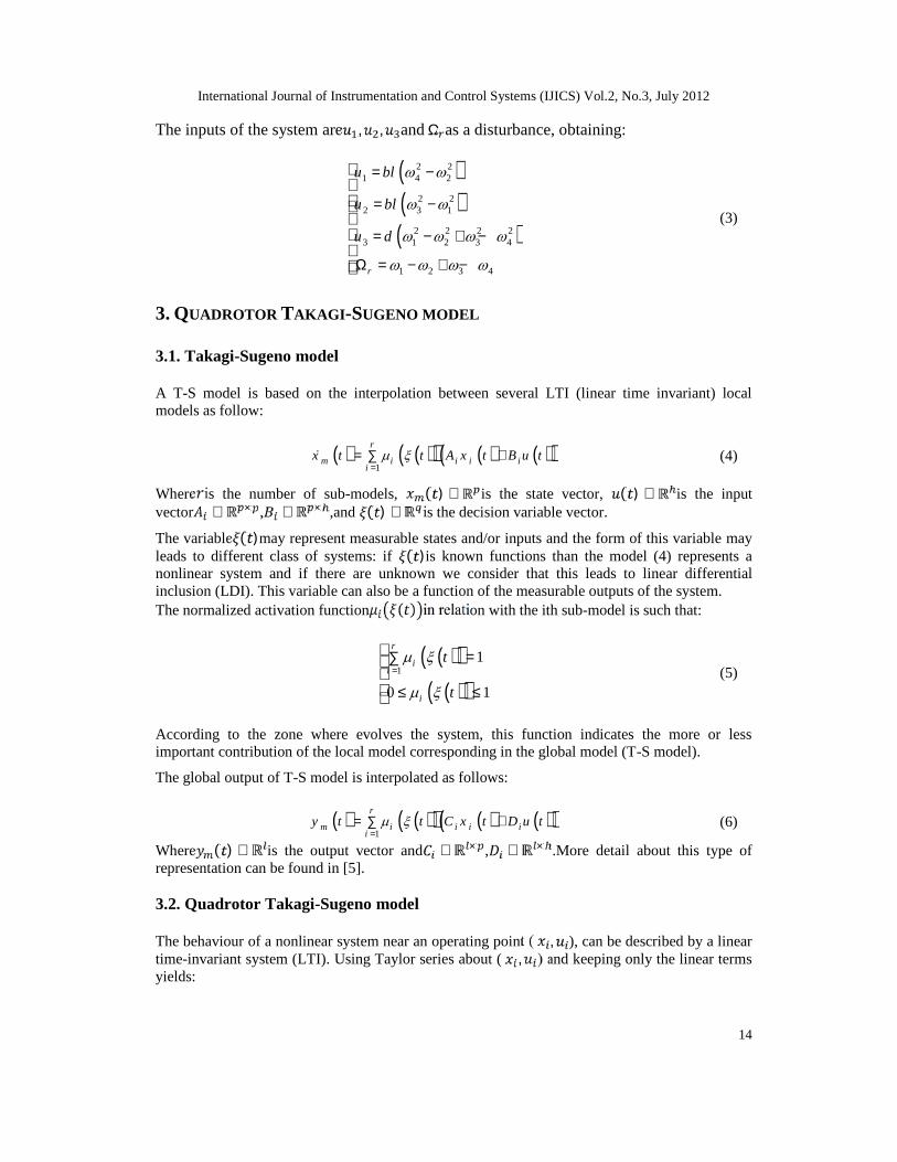
The inputs of the system are , , and Ω as a disturbance, obtaining:
( )( )
( )
2 21 4 2
2 22 3 1
2 2 2 23 1 2 3 4
1 2 3 4r
u bl
u bl
u d
= −
= −
= − + −
Ω = − + −
(3)
3. QUADROTOR TAKAGI-SUGENO MODEL
3.1. Takagi-Sugeno model
A T-S model is based on the interpolation between several LTI (linear time invariant) localmodels as follow:
( ) ( )( ) ( ) ( )( )1
r
m i i i ii
x t t A x t B u t =
= +∑ (4)
Where is the number of sub-models, ( ) ∈ is the state vector, ( ) ∈ is the inputvector ∈ × , ∈ × ,and ( ) ∈ is the decision variable vector.
The variable ( )may represent measurable states and/or inputs and the form of this variable mayleads to different class of systems: if ( )is known functions than the model (4) represents anonlinear system and if there are unknown we consider that this leads to linear differentialinclusion (LDI). This variable can also be a function of the measurable outputs of the system.The normalized activation function ( ) in relation with the ith sub-model is such that:
( )( )( )( )
11
0 1
r
ii
i
t
t
=
=∑
≤ ≤
(5)
According to the zone where evolves the system, this function indicates the more or lessimportant contribution of the local model corresponding in the global model (T-S model).
The global output of T-S model is interpolated as follows:
( ) ( )( ) ( ) ( )( )1
r
m i i i ii
y t t C x t D u t =
= +∑ (6)
Where ( ) ∈ is the output vector and ∈ × , ∈ × .More detail about this type ofrepresentation can be found in [5].
3.2. Quadrotor Takagi-Sugeno model
The behaviour of a nonlinear system near an operating point ( , ), can be described by a lineartime-invariant system (LTI). Using Taylor series about ( , ) and keeping only the linear termsyields:
International Journal of Instrumentation and Control Systems (IJICS) Vol.2, No.3, July 2012
15
( ) ( )( ) ( )( ) ( )i i i i i ix t A x t x B u t u f x ,u= − + − + (7)
Which can written as
( ) ( ) ( )i i ix t A x t B u t d= + + (8)
With:
( ),
i
i
i
f x uA
x x xu u
∂=
∂ ==
,( ),
i
i
i
f x uB
u x xu u
∂=
∂ ==
, ( ) ( ),f x u x t= , ( ),i i i i i i id f x u A x B u= − −
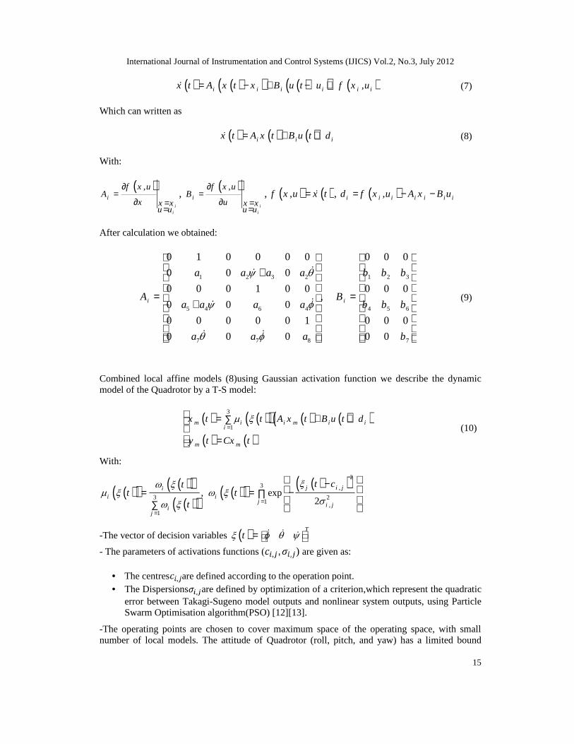
After calculation we obtained:
1 2 3 2 1 2 3
5 4 6 4 4 5 6
7 7 8 7
0 1 0 0 0 0 0 0 0
0 0 0
0 0 0 1 0 0 0 0 0,
0 0 0
0 0 0 0 0 1 0 0 0
0 0 0 0 0
i i
a a a a b b b
A Ba a a a b b b
a a a b
+
= = +
(9)
Combined local affine models (8)using Gaussian activation function we describe the dynamicmodel of the Quadrotor by a T-S model:
( ) ( )( ) ( ) ( )( )( ) ( )
3
1m i i m i i
i
m m
x t t A x t B u t d
y t Cx t
=
= + +∑
=
(10)
With:
( )( ) ( )( )( )( )
( )( ) ( )( )23 ,
3 21 ,
1
, exp2
j i jii i
j i jij
t ctt t
t
=
=
−= = −∏
∑
-The vector of decision variables ( ) Tt =
- The parameters of activations functions ( , , , ) are given as:
• The centres , are defined according to the operation point.• The Dispersions , are defined by optimization of a criterion,which represent the quadratic
error between Takagi-Sugeno model outputs and nonlinear system outputs, using ParticleSwarm Optimisation algorithm(PSO) [12][13].
-The operating points are chosen to cover maximum space of the operating space, with smallnumber of local models. The attitude of Quadrotor (roll, pitch, and yaw) has a limited bound

International Journal of Instrumentation and Control Systems (IJICS) Vol.2, No.3, July 2012
16
(− 2 ≤ ≤ 2⁄⁄ ,− 2 ≤ ≤ 2⁄⁄ , − ≤ ≤ ), for this reason we use three local modelsto cover this space.Linear local model are defined in this table as follow:
Table 1. Operation Points Parameters.
N° O.P Parameters
1 0.523 rad s = = = − [ ]0 0.1964 0 0.1964 0 0T−
2 0 rad s = = = [ ]0 0 0 0 0 0T
3 0.523 rad s = = = [ ]0 0.2771 0 0.2771 0 0T−
3.3. Quadrotor Takagi-Sugeno model validation
The input signals (rotors velocities) most appropriated for the local models network validation,and exit all dynamic of the system in this case is the Pseudo-Random Binary Signal (SBPA) dueto different causes:the SBPA signal has a null mean and a variance that close to one, whichallows the excitation of very good frequency range (dynamics system) without moving away toomuch the system from the operating point. It is periodic deterministic signal white-noise-likeproperties very adapted for identification and validation tasks.
A typical value of the amplitude of the SBPAis from 0.5% to 5% from the value of the operatingpoint to which the SBPA is applied, in this case the amplitude of the SBPA is given as
0.005SBPA eq eqA = ± ∗ ,4eq
mg
b = .
To validate the synthesized Takagi-Sugeno model a SBPA (input signal) is used, for Quadrotornonlinear system and the T-S model. We simulate the two systems in parallel and we compare theresulting curves.
Figure 3 present the input signals of Quadrotor, which are SBPA signals with variable amplitude.This SBPA excite all dynamic of the system.
Figure 3. Validation input signals
0 0.5 1 1.5 2 2.5 3-8
-6
-4
-2
0
2
4
6
8x 10⁻³
Time (s)
Rol
l Cou
ple
U 1 (N.m
)
0 0.5 1 1.5 2 2.5 3-8
-6
-4
-2
0
2
4
6
8x 10⁻³
Time (s)
Pitc
h C
oupl
e U 2 (N
.m)
0 0.5 1 1.5 2 2.5 3-6
-4
-2
0
2
4
6x 10⁻⁴
Time (s)
Yaw
Cou
ple
U 3 (N.m
)

International Journal of Instrumentation and Control Systems (IJICS) Vol.2, No.3, July 2012
17
Figure 4 present the attitude of Quadrotor and corresponding output of T-S model. We show theresemblance between the output of T-S model and Quadrotor nonlinear system. These resultsprove the quality of the approximation of a nonlinear system by a T-S model.
Figure 5 present attitude acceleration errors, which are close to a white-noise with null mean anda variance that close to one. Saw the designing T-S model give good approximation of theQuadrotor nonlinear system for a specific region of the operating space.
Figure 4. Takagi-Sugeno model and Quadrotor’s outputs
Figure 5. Attitude acceleration errors
4. CONTROLLER DESIGN
4.1. State feedback controller
The concept of PDC, following the terminology [8], is utilized to design state-feedback controlleron the basis of the T-S model (10). Linear control theory can be used to design the control law,because T-S model is described by linear state equations. The controller law is a convex linearcombination of the local controller associated with the corresponding local sub-model. It canpresent as:
( ) ( )( ) ( ) ( )( ) ( )1 1
r r
i i i ii i
U t t u t t K x t = =
= − = −∑ ∑ (11)
With: is r vector of feedback gains.
It should be noted that the designed controller shares the same models sets with T-S models, andresulting controller (11) is nonlinear in general since the coefficient of the controller dependsnonlinearly on the system input and output via the weighting functions. Substituting (11) into(10), the closed-loop T-S model can be represented by:
0 0.5 1 1.5 2 2.5 3-2
0
2
4
6
8
10
12
14
16
Time (s)
Rol
l ang
leφ
(deg
)
NonLinear SystemLocal Models Network
0 0.5 1 1.5 2 2.5 3-2
-1
0
1
2
3
4
5
6
7
8
Time (s)
Pitc
h an
gle
θ (d
eg)
NonLinear SystemLocal Models Network
0 0.5 1 1.5 2 2.5 3-0.2
0
0.2
0.4
0.6
0.8
1
1.2
1.4
Time (s)
Yaw
ang
leψ
(deg
)
NonLinear SystemLocal Models Network
0 0.5 1 1.5 2 2.5 3-10
-8
-6
-4
-2
0
2
4x 10⁻⁵
Temps (s)
Rol
l acc
eler
atio
n er
rorφ
(deg
)
0 0.5 1 1.5 2 2.5 3-4
-3
-2
-1
0
1
2
3
4x 10⁻⁵
Temps (s)
Pitc
h ac
cele
ratio
n er
rorθ
(deg
)
0 0.5 1 1.5 2 2.5 3-8
-6
-4
-2
0
2
4
6x 10⁻⁸
Temps (s)Y
aw a
ccel
erat
ion
erro
rψ (d
eg)

International Journal of Instrumentation and Control Systems (IJICS) Vol.2, No.3, July 2012
18
( ) ( )( ) ( )( )( ) ( )1 1
r r
i j i i ji j
x t t t A B K x t = =
= −∑ ∑ (12)
The constant was neglected in this formulate, because the control law can compensate the effectof this bias term.
4.1. Stabilisation using PDC
A sufficient quadratic stability condition derived by Tanaka and Sugeno[14] for ensuring stabilityof (12) is given as follows:
Theorem 1: The closed-loop T-S model (12) is quadratic-ally stable for some stablefeedback (via PDC scheme) if there exists a common positive definite matrix such that:
( ) 2
0
0, , ,2 2
Tii ii r
T
ij ji ij jir
G P PG i I
G G G GP P i j I i j
+ < ∀ ∈
+ ++ < ∀ ∈ <
(13)
With: = − , ( ) ( ) ≠ 0.
Which is an LMI in when are predetermined.However, our objective is to design the gainmatrix such that conditions (13) are satisfied. That is, are not pre-determined matrices anylonger, but matrix variables.This is the quadratic stability problem and can be recast as an LMIfeasibility problem. With linear fractional transformation = and = , we may rewrite(13) as an LMI problem in , and [15]:
( ) 2
11 1
1
0
0,
2 0, , ,
0
T T Ti i i i i i ii r
T T T Ti i j j j i i j
T Ti j j i ij r
n
n nn
X
XA A X N B B N S i I
XA A X XA A X N B B N
N B B N S i j I i j
S S
S S
>+ − − + < ∀ ∈
+ + + − −
− − + ≤ ∀ ∈ <
>
(14)
With: = , ∀ ∈ 1, … , , are symmetric matrix.
4.2. LMI formulation for Pole placement
In order to achieve some desired transientperformance, a pole placement should beconsidered.For many problems, exact poleassignment may not be necessary; it suffices tolocate the pole ofthe closed loop system in a sub-regionof the complex left half plane. This sectiondiscusses a poleassignment in LMI regions. For this purpose, we introduce the following LMI-basedrepresentation of stability regions [16] [17].
Definition:A subset D of the complex planeis called an LMI region if there exist asymmetricmatrix = . and a matrix = . such that:

International Journal of Instrumentation and Control Systems (IJICS) Vol.2, No.3, July 2012
19
( ) : 0DD z f z= ∈ < (15)
Where: ( ) = + + , ∀ , 1, … , Theorem 2:A matrix is D-stable if and onlyif there exists a symmetric positive definitematrix such that:
( ), 0DM X A < (16)
Where: ( ) ( ) ( ),TT
DM X A X A X A X = ⊗ + ⊗ + ⊗
For example, a circle region D centred at – , 0 with radius > 0can be obtained by takingthematrices and as follows:
q
q
−
=−
, and0 1
0 0 =
What makes it possible to obtain the expression ofthe characteristic function:
( )D
z qf z
z q
∗− +=
+ −
(17)
As it is shown in figure 6, this region which includecircular region, allows fixing a lower bound
on boththe exponential decay rate: − and the dampingratio: = 1 − ( ⁄ )( < )ofthe closed-loopresponse, and thus is very common in practical control design.
Figure 6. Circular region (D) for pole location
Since the prescribed LMI region (17) will be addedas supplementary constraints to these ofthetheorem 1, it should be noted that itonly suffices to locate the poles of the dominantterm in theprescribe LMI regions, i.e. the case of = . It follows that the closed loop T-S model (12) is D-stable if there exists asymmetric matrix such that [18]:
Im
Re
nMax .
dMax .
q
cos =

International Journal of Instrumentation and Control Systems (IJICS) Vol.2, No.3, July 2012
20
( )( )
T
i i j
i i j
X qX X A B K
qX A B K X X
− + +
+ + −
(18)
With the same change of variables = leads to thefollowing LMI formulation:
,T T Ti i i
i i
X qX XA B Ni j
qX XA B N X
− + +=
+ + −
(19)
By combining Theorems 1 and 2 leads to the following LMI formulation of two objectives state-feedback synthesis problem, such that the resulting controller meets both the global stability andthe desired transient performance simultaneously. The closed loop T-S model (12) is stabilizablein the specified region D ifthere exists asymmetric matrix such that [16]:
( ) 2
11 1
0
0,
2 0, , ,
0 ,
T T Ti i i i i i ii r
T T T Ti i j j j i i j
T Ti j j i ij r
T T Ti i i
r
i i i
n
X
XA A X N B B N S i I
XA A X XA A X N B B N
N B B N S i j I i j
X qX XA N Bi I
qX A X B N X
S S
>+ − − + < ∀ ∈
+ + + − −
− − + ≤ ∀ ∈ <
− + +< ∀ ∈ + + −
1
0
n nnS S
>
(20)
With: = , = , ∀ ∈ 1, … , 4.3. State feedback gains calculation
Using Theorem 1 and 2; can design a nonlinear state feedback controller that guarantees globalstability while provides desired transient behaviour by constraint the closed-loop poles inD. Thestability regionDis a circle of centre( , 0)and radius and the LMI synthesis is performed for aset of values( , ) = (4,1).
Then the LMI region has the following characteristic function:
( ) 1 4
4 1D
zf z
z
∗− +=
+ −
(21)
This circle region puts a lower bound on both exponential decay rate − = 3 ⁄ and
damping ratio = 1 − ( ⁄ ) = 0.97of the closed-loop response.By solving LMI feasibilityproblem (20), we can obtain a positive symmetric matrix (by interior-point method in MatlabLMI-toolbox), and stat feedback Matrix .

International Journal of Instrumentation and Control Systems (IJICS) Vol.2, No.3, July 2012
21
4.4. Simulation results
The controller described above was simulated for the nonlinear Quadrotor system. Simulationsare made for initial values equal to( , , ) = (20, 40, 60) for rollangle,(−20, −40, −60) for pitch angle, and (40, 80, 120) for yaw angle, and equal tozeros for tracking simulation. The values of the model parameters used for simulations arethe following:= 0.486 , = 0.225 , = 9.81 , = 3.23 × 10 . ( . )⁄⁄ , = 2.98 ×10 ( . )⁄ , = = 3.82 × 10 . , = 7.65 × 10 . , = =5.567 × 10 , = 6.354 × 10 .
The results of state feedback controller are shown in Figure 7 which indicates the output ofQuadrotor nonlinear system (Quadrotor attitude, Roll, Pitch, and Yaw), and the correspondingcontrol inputs in figure 8.
From the resultsof figure 7, 8; it can be noticed that state the feedback controller provides goodtransient performance(stabilization time, overtaking…), while, controller give stable responseregardless of any initial displacement.The control inputs are smoother and realizable.
Figure 7. Quadrotor Attitude ( , , ) for state feedback controller
Figure 8. Quadrotor control inputs ( , , ) for state feedback controller
To check the robustness of the proposed controls two tests are used; the first again measurementnoise, and the second: again parameter variations.
• Measurement noise of a normal distribution, a covariance equal to 1, a zero mean, andamplitude close to 0.05 are added to the measured variables as shown in figures 10, 11.
• A change of 100% for ( , , ) parameters and 40% variation of parameters areperformed between 20 to 40 seconds (figures 12, 13).
Figure 10 represent measurement noisetest, for Quadrotor attitude tracking (Roll, Pitch, andYaw), with a sinusoidal trajectory, we can clearly see a good tracking of desired trajectories,
0 2.5 5 7.5 10 12.5 15-10
0
10
20
30
40
50
60
70
80
90
Time (s)
Rol
l Ang
leΦ
(deg
)
Φd
Φ0=20deg
Φ0=40deg
Φ0=60deg
0 2.5 5 7.5 10 12.5 15-60
-50
-40
-30
-20
-10
0
10
Time (s)
Pitc
h A
ngle
Θ (d
eg)
Θd
Θ0=-20deg
Θ0=-40deg
Θ0=-60deg
0 2.5 5 7.5 10 12.5 15-20
0
20
40
60
80
100
120
Time (s)
Yaw
Ang
leΨ
(deg
)
Ψd
Ψ0=40deg
Ψ0=80deg
Ψ0=120deg
0 2.5 5 7.5 10 12.5 15-0.14
-0.12
-0.1
-0.08
-0.06
-0.04
-0.02
0
0.02
Time (s)
Rol
l Cou
ple
U 1 (N
.m)
0 2.5 5 7.5 10 12.5 15-0.01
0
0.01
0.02
0.03
0.04
0.05
0.06
Time (s)
Pitc
h C
oupl
e U
2 (N
.m)
0 2.5 5 7.5 10 12.5 15-0.05
-0.04
-0.03
-0.02
-0.01
0
0.01
0.02
0.03
Time (s)
Yaw
Cou
ple
U 3 (N
.m)

International Journal of Instrumentation and Control Systems (IJICS) Vol.2, No.3, July 2012
22
which confirms the robustness of the proposed controlleragainmeasures noise. Figure 11represent inputs control system.
Figure 9. Measures noise added
Figure 10. Quadrotor Attitude ( , , ) for measurement noise test
Figure 11. Quadrotor control inputs ( , , ) for measurement noise test
Figure 12. Quadrotor Attitude ( , , ) for parameter variation test
0 10 20 30 40 50 60-0.08
-0.06
-0.04
-0.02
0
0.02
0.04
0.06
0.08
Time (s)
Add
ed N
oise
(rad
)
0 10 20 30 40 50 60-20
-15
-10
-5
0
5
10
15
20
25
Time (s)
Rol
l Ang
leΦ
(deg
)
ΦdΦ
0 10 20 30 40 50 60-20
-15
-10
-5
0
5
10
15
20
25
Time (s)
Pitc
h A
ngle
Θ (d
eg)
ΘdΘ
0 10 20 30 40 50 60-40
-30
-20
-10
0
10
20
30
40
Time (s)
Yaw
Ang
leΨ
(deg
)
ψ dψ
0 10 20 30 40 50 60-0.02
-0.015
-0.01
-0.005
0
0.005
0.01
0.015
Time (s)
Rol
l Cou
ple
U 1 (N
.m)
0 10 20 30 40 50 60-0.02
-0.015
-0.01
-0.005
0
0.005
0.01
0.015
Time (s)
Pitc
h C
oupl
e U
2 (N
.m)
0 10 20 30 40 50 60-0.03
-0.02
-0.01
0
0.01
0.02
0.03
0.04
0.05
Time (s)
Yaw
Cou
ple
U 3 (N
.m)
0 10 20 30 40 50 60-20
-15
-10
-5
0
5
10
15
20
Time (s)
Rol
l Ang
leΦ
(deg
)
ΦdΦ
0 10 20 30 40 50 60-20
-15
-10
-5
0
5
10
15
20
Time (s)
Pitc
h A
ngle
Θ (d
eg)
ΘdΘ
0 10 20 30 40 50 60-30
-20
-10
0
10
20
30
Time (s)
Yaw
Ang
leΨ
(deg
)
ψ dψ

International Journal of Instrumentation and Control Systems (IJICS) Vol.2, No.3, July 2012
23
Figure 13. Quadrotor control inputs ( , , ) for parameter variation test
Figure 12 represent parameter variationstest, for Quadrotor attitude tracking (Roll, Pitch, andYaw), with a sinusoidal trajectory, we can clearly see a good tracking of desired trajectories,which confirms the robustness of the proposed controlleragainparameter variation. Figure 13represent inputs control system.
5. CONCLUSIONS
In this paperthe problem of Quadrotor attitude stabilization isresolved using T-S modeland statefeedback controller. A T-S model is designed for Quadrotor modelling. We use a QuadraticLyapunov function to prove the stability of closed loop system.The designed methodologyisbased on ParallelDistributed Compensation technique and pole placement in LMIregion.Simulation results showed that the proposedcontroller providesstable response regardlessof any initial conditions.In addition, it is observed that theproposed state feedback controllerprovidessuperior stability robustness against parameter variations and measurement noise.
APPENDIX
Parameters of iA and iB matrix
( )
( )
( )
51 1 1
5 2
6 2 22
3 337
4 14 8
1
1
, , ,
rfax rryx x x r
fayy z y yr
y xx
rr x yr
xxz
rz x faz
yy z
JK Jaa b CII I I Jb C
KI I I IJa b Ca
I II
JJ I I b Ca a II IJI I K b Ca a II I
= Ω=− =− + =− + − =− =− =
− =−=− Ω =
− == =−
6 3
7
1
r
y
z
Jb C
I
bI
=− =
0 10 20 30 40 50 60-2
-1
0
1
2
3
4
5x 10⁻³
Time (s)
Rol
l Cou
ple
U 1 (N
.m)
0 10 20 30 40 50 60-6
-5
-4
-3
-2
-1
0
1x 10⁻³
Time (s)
Pitc
he C
oupl
e U
2 (N
.m)
0 10 20 30 40 50 60-6
-5
-4
-3
-2
-1
0
1x 10⁻³
Time (s)
Pitc
he C
oupl
e U
2 (N
.m)
International Journal of Instrumentation and Control Systems (IJICS) Vol.2, No.3, July 2012
24
REFERENCES
[1] P. Brisset, (2004) "Drones civils Perspectives et réalités", Ecole Nationale del’Aviation Civile Aout2004.
[2] T. Madani& A. Benallegue, (2006) "Backstepping Sliding Mode Control Applied to a MiniatureQuadrotor Flying Robot", IEEE Conference on Industrial Electronics, pp. 700-705.
[3] Y. Yu, J.Changhong, & W.Haiwei, (2010) "Backstepping control of each channel for a Quadrotoraerial robot", International Conference on Computer, Macaronis, Control and Electronic Engineering(CMCE), pp. 403-407.
[4] J. Novák. (2007) “linear system identification and control using local model networks”. Athesissubmitted in fulfilment of the requirements for the PhD degree, Faculty of Applied Informatics,Tomas Bata University, Zlín, Czech.
[5] T. Takagi & M. Sugeno, (1985) "Fuzzy identification of systems and its applications to model andcontrol", IEEE Transactions on Systems, Man, and Cybernetics, vol. 15, pp. 116–132.
[6] M. Chadli, D. Maquin& J.Ragot, (2001) "on the stability analysis of multiple models",in Proceedingof the ECC, Portugal, 2001, pp. 1894-1899.
[7] R. Murray-Smith & T. A. Johansen, (1997) multiple model approaches to modelling and control,Taylor and Francis Publishers. France, 1997.
[8] H. O. Wang, K. Tanaka, & M. Griffin, (1996) "An approache to fuzzy controle of non linear systems :stability and design issues," IEEE Transaction on fuzzy system, vol. 4, pp. 14-23.
[9] K. Tanaka, . T. Ikeda, & Y. Y. He, (1998) "Fuzzy regulators and fuzzy observers : relaxed stabilityconditions and LMI-based design," IEEE Transaction on fuzzy system, vol. 6, pp. 250-256.
[10] S. Boyd, L. El Ghaoui, E. Feron, & V. Balakrishnan (1994) "Linear Matrix Inequalities in System andControl Theory," SIAM, Philadelphia, USA.
[11] H .Bouadi, S. S. Cunha, A. Drouin,& F. M. Camino,(2011) "Adaptive Sliding Mode Control forQuadrotor Attitude Stabilization and Altitude Tracking",IEEE International Symposium onComputational Intelligence and Informatics, pp. 449-455.S.
[12] F. Yacef& F. Boudjema,(2011) "Local Model Network for non linear modelling and control of anUAV Quadrotor", International Conference on Automatic and Mechatronics (CIAM), November 22-24, Oran, Algeria, pp. 247-252.
[13] F. Yacef, O. Bouhali, H. Khebbache& F. Boudjema, (2012) "Takagi-Sugeno Model for QuadrotorModelling and Control Using Nonlinear State Feedback Controller", International Journal of ControlTheory and Computer Modelling (IJCTCM),Vol.2, No.3, pp. 9-24, May 2012.
[14] K. Tanaka & M. Sugeno, (1992) "Stability analysis and design of fuzzy control systems", Fuzzy Setand Systems, vol. 45, pp. 135-156.
[15] M. Chadli, (2002)"Stability and control of multiple models:LMI approach", INPL thesis (in French),France.mchadli.voila.net/THESECHADLI.pdf.
[16] S. K. Hong & Y. Nam, (2003) "Stable fuzzy control system design with pole-placement constraint: anLMI approach",Computers in Industry, vol. 51, pp. 1-11.
[17] M. Chadli, D. Maquin, J. Ragot, (2002) "Static Output Feedback for Takagi-SugenoSystems: an LMIApproach", Proceedings of the 10th Mediterranean Conference on Control and Automation,July 9-12,Lisbon, Portugal.
[18] M. Chilali& P. Gahinet, (1996) "H∞ Design with pole placement constraints: an LMI approach",IEEETransaction on Automatic Control, vol. 41, pp. 358-367.

International Journal of Instrumentation and Control Systems (IJICS) Vol.2, No.3, July 2012
25
Authors
FouadYacefis currently a Ph.D. student at the Automatic Control Department ofJijelUniversity, Algeria. He received the Engineer degree in Automatic Control fromJijelUniversity, Algeria in 2009, and Magister degree in Automatic Controlfrom theMilitaryPolytechnic School of Algeria(EMP), in November 2011.Since December2011, he has been a researcher in Automatic Laboratory of Jijel (LAJ). His researchinterests include Aerialrobotics, linear and nonlinear control, analysis and design ofintelligent control and renewable energy systems.
HichamKhebbacheis Graduate student (Magister) of Automatic Control at theElectrical Engineering Department of Setif University, ALGERIA. He received theEngineer degree in Automatic Control from Jijel University, ALGERIA in 2009.Now he is with AutomaticLaboratory of Setif (LAS). His research interests includeAerial robotics, Linear and Nonlinear control, Robust control, Fault tolerant control(FTC), Diagnosis, Fault detection and isolation(FDI).
HanaBoudjedir received the Engineer degree and Magister degree in AutomaticControl from Jijel University, Algeria in 2008, and 2010, respectively.She iscurrently a Ph.D. student at the Automatic Control Department of JijelUniversity,Algeria.Since December 2011, she has beena researcher in Automatic Laboratoryof Jijel (LAJ). Her research interests includeaerialrobotics, nonlinear controlsystems, analysis and design of intelligent control systems.
Omar Bouhali He received the engineer degree and the master degree in automaticfrom national polytechnic school of Algeria, in 1996 and 1998 respectively. Hereceived the Ph. D. degree from the Central School of Lille, France and NationalPolytechnic School of Algeria in 2007. Since 1998, he has been a lecturer in theautomatic department of Jijel University, Algeria. And he is a researcher inAutomatic Laboratory of Jijel (LAJ). He is working in the development ofrenewable energy based power systems with inertial storage using multilevelconverters.