Embed Size (px)
Citation preview

Switching Model Predictive Attitude Control for a
Quadrotor Helicopter subject to Atmospheric
Disturbances
Kostas Alexis a, George Nikolakopoulos b,∗ and Anthony Tzes a
aElectrical and Computer Engineering Department,
University of Patras,
Rio 26500, GREECE a
b Computer Science, Electrical and Space Engineering Department,
Lulea University of Technology,
Lulea SE-97753, SWEDEN b
Abstract
In this article a Switching Model Predictive Attitude Controller for an Unmanned quadrotor
Helicopter subject to atmospheric disturbances is presented. The proposed control scheme
is computed based on a Piecewise Affine (PWA) model of the quadrotor’s attitude dy-
namics, where the effects of the atmospheric turbulence are taken into consideration as
additive disturbances. The switchings among the PWA models are ruled by the rate of the
rotation angles and for each PWA system a corresponding model predictive controller is
computed. The suggested algorithm is verified in experimental studies in the execution of
sudden maneuvers subject to forcible wind disturbances. The quadrotor rejects the induced
wind–disturbances while performing accurate attitude tracking.
Key words: Unmanned Quadrotor Helicopter, Model Predictive Control, Switching
Control, Atmospheric Disturbances.
Preprint submitted to Elsevier 29 August 2011

1 Introduction
Recent innovative designs of Vertical Take–Off and Landing (VTOL) Unmanned
Aerial Vehicles (UAVs), have generated great interest in the control scientific com-
munity (Tayebi and McGilvray (2006); Kondak et al. (2007)). Within the family of
the VTOL UAVs, Unmanned Quadrotor Helicopters (Hoffmann et al. (2007)) that
base their operation in the appropriate control of four rotors, have received a grow-
ing attention, mainly due to their capability to outperform most of other types of
helicopters on the issues of maneuverability, survivability, simplicity of mechanics
and increased payloads (Bouabdallah et al. (2007)).
The quadrotors’ hovering ability makes possible an extended area of applications
for which fixed wing aircrafts are not suitable. Examples include forest fire surveil-
lance (Merino et al. (2005); Alexis et al. (2009)), inspection of buildings and bridges
(Metni and Hamel (2007)), wildfire monitoring, and military applications. During
these missions precise trajectory tracking combined with effective disturbance at-
tenuation is required. Quadrotors have several advantages compared to other rotor-
craft designs including: a) the simplicity of their mechanical structure, b) the use of
four small propellers resulting in a more fault–tolerant mechanical design capable
of aggressive maneuvers at low altitude, c) good maneuverability and d) increased
payload (Bouabdallah et al. (2007)).
The quadrotor’s model is highly non–linear with certain parameters being depen-
∗ Corresponding AuthorEmail address: [email protected] (George Nikolakopoulos).
2

dent on the characteristics of the flight (Bouabdallah and Siegwart (2007)). More-
over, during flights in low–altitudes, quadrotors are prone to sudden wind–gusts that
can significantly affect their flight performance and even cause instability. There-
fore the development of specialized controllers, that could take under considera-
tion the quadrotor’s modeling non–linearities and the uncertainties while reacting
to such sudden wind–gusts is desired.
In the relevant literature of quadrotors, the problem of control design has been
addressed by a large number of publications that mainly focus in the following
areas: a) PID control and LQ–Regulation in (Bouabdallah et al. (2004)), b) Sliding
Mode control (Waslander et al. (2005)), c) Backstepping control (Bouabdallah and
Siegwart (2007)), d) Integral predictive–nonlinear H∞ control (Raffo et al. (2010)),
e) Constrained Finite Time Optimal Control Scheme (Alexis et al. (2010a,b)), and
f) bounded control (Guerrero-Castellanos et al. (2011)). Moreover in the existing
literature of rotorcrafts, certain simulation studies have focused on the effects of
the environmental disturbances (Costello (1992); Yang et al. (2009)); in general an
experimental verification is needed to validate the efficiency of the noted efforts.
On the effect of environmental disturbances to the performance of rotorcrafts, the
majority of the recent published work in the control–community has focused on
theoretical and simulation studies (Costello (1992); Yang et al. (2009); Perhinsch
(1998); Martini et al. (2009)) with very few experimental articles focusing in the
area of disturbance rejection. Extensive advanced aerodynamic models have re-
cently appeared in the area of quadrotors (Pounds et al. (2010); Bristeau et al.
(2009); Pounds et al. (2006)) with a direct implication on the control performance.
The work presented in this article focuses on the problem of controlling the attitude
of a quadrotor in the presence of external wind–gust disturbances. The novel contri-
3

butions of the proposed control design scheme are: a) the presentation of an optimal
control design approach for the attitude control of a quadrotor, and b) the experi-
mental application and evaluation of the suggested control scheme in a prototype
quadrotor under a wind–gust disturbance.
The controller relies on the principle of Model Predictive Control (MPC) based on a
Piecewise Affine (PWA) model description of the quadrotor’s linearized model for
a certain motion. In this approach the wind–turbulence affects the nominal system
and is taken under consideration in the system model description as an affine term
with an a priori known worst case bound.
Model predictive control determines the control input via a receding horizon op-
timal control approach based on the open–loop model of the quadrotor. The main
appeal of MPC is the ability to: a) enforce pointwise–in–time constraints, b) count
for additive disturbances at the phase of system modeling, while c) providing the
control designer with the direct capability to shape the transient response by ad-
justing the weights in the objective function being minimized. These attributes are
quite important in accurate aggressive maneuvers under wind–gusts of rotorcrafts
in general (Alexis et al. (2010c)) and quadrotors in particular.
This article is organized as follows. In Section 2 the quadrotor’s dynamics are pre-
sented while in Section 3 the mathematical formulation of the novel control design
scheme based on a Switching variation of a MPC is analyzed. In Section 4 experi-
mental studies, from multiple test–cases, are presented that prove the efficacy of the
proposed scheme in the absence/presence of wind disturbances and in comparison
with other controllers. Finally in Section 5, the conclusions are drawn.
4

2 Quadrotor’s Dynamics
The model of the quadrotor utilized in this work, assumes that the structure is rigid
and symmetrical, the center of gravity and the body fixed frame origin coincide,
the propellers are rigid and the thrust and drag forces are proportional to the square
of propeller’s speed. The quadrotor, as a rigid body, is characterized by the linked
body fixed frame characterized by B = B1, B2, B3, where the B1 axis is in the
helicopter normal flight direction, B2 is orthogonal to B1 and positive to starboard
in the horizontal plane, whereas B3 is oriented in the ascendant sense and orthogo-
nal to the plane B1OB2, as presented in Figure 1.
Ey
θ
Ex
Ez
B1 φ
B3
ψB2
Fig. 1. Quadrotor helicopter configuration frame system
The aerodynamic forces and moments acting on the quadrotor during a hovering
flight segment correspond to the thrust (τ), hub forces (h) and drag moment (md)
due to vertical, horizontal and aerodynamic forces respectively, followed by the
rolling moment (mr) related to the integration over the entire rotor of the lift of
each section, acting at a given radius. An extended formulation of these forces and
moments can be found at (Bouabdallah and Siegwart (2007)).
Let a) the translation–vector movement of the quadrotor’s center of mass be ξ =
[x, y, z]T , b) the rotations of the quadrotor with respect to the ground be η =
5

[ϕ , θ , ψ ]T , then the system’s dynamics can be formulated as:
xN =
ϕ
ϕ
θ
θ
ψ
ψ
z
z
x
x
y
y
=
ϕ
θ ψ Iyy−IzzIxx
+ θ JrIxx
Ωr +laIxx
U2
θ
ϕ ψ Izz−IxxIyy
− φ JrJyy
Ωr +laIyy
U3
ψ
θ φ Ixx−IyyIzz
+ 1Izz
U4
z
g− (cosϕ cosθ)U1ms
x
(cosϕ sinθ cosψ+sinφ sinψ)U1ms
y
(cosϕ sinθ sinψ−sinφ cosψ)U1ms
+
0
W1
0
W2
0
W3
0
W4
0
W5
0
W6
(1)
where ms is the mass of the system, g the gravity acceleration, Wi, i= 1, . . . ,6 terms
represent the effect of the wind gusts on the quadrotor’s angular and translational
accelerations in the form of additive disturbances, and Ui, i = 1, . . . ,4 correspond
to the control actions that are dependent on the four motors’ angular velocities
Ωi, i = 1, . . . ,4; the control vector uN is formed by the introduction of one auxiliary
variable Ωr, as uN = [U1, . . . ,U4,Ωr]T .
The control actions are calculated as:
6

uN =
U1
U2
U3
U4
Ωr
=
b(Ω21 +Ω2
2 +Ω23 +Ω2
4)
b(−Ω22 +Ω2
4)
b(Ω21 −Ω2
3)
d(−Ω21 +Ω2
2 −Ω23 +Ω2
4)
−Ω1 +Ω2 −Ω3 +Ω4
. (2)
The utilized quadrotor’s parameters, in equations (1), (2), are listed in Table 1.
Table 1
Quadrotor Model Parameters
Ixx (Iyy) [Izz] X (Y) [Z]-axis inertia component
la Quadrotor Arm length
b (d) Thrust (Drag) coefficient
Jm (Jp) Motor (Propeller) Inertia
Jr = Jm + Jp/4 Rotor Inertia
The input U1 is related to the total thrust, while the inputs U2, U3, U4 are related to
the rotations of the quadrotor, and Ωr is the overall residual propeller angular speed.
The angles η and their derivatives η are independent of the translational–vector
component (ξ , ξ ) the aforementioned system’s attitude dynamics in equation (1)
can be decoupled from the translational ones (Bouabdallah (2007)), since in general
the attitude–subsystem is faster than the translational–subsystem.
The attitude equations correspond to the first six equations of the nonlinear ODE
7

in (2). If small perturbations around the operating points x,j =[0, ϕ, j,0, θ , j,0, ψ, j]
are considered (i.e., ϕ = ϕ, j +δ ϕ j), then the PWA linearized attitude equations of
motion can be inferred as:
x = A jx+B jδu+ ˜δwN . (3)
where x =[δϕ j,δ ϕ j,δθ j,δ θ j,δψ j,δψ j] and δu = [δU1, δU2, δU3, δU4, δΩr]
′ ,
δ wN = [0, δW1, 0, δW2, 0,δW3] , and
A j =
0 1 0 0 0 0
0 0 0 Iyy−IzzIxx
ψ, j 0 Iyy−IzzIxx
θ , j
0 0 0 1 0 0
0 Izz−IxxIyy
ψ, j 0 0 0 Iyy−IxxIyy
φ, j
0 0 0 0 0 1
0 Ixx−IyyIzz
θ , j 0 Ixx−IyyIzz
φ, j 0 0
(4)
8

B j =
0 0 0 0 0
0 laIxx
0 0 JrIxx
θ , j
0 0 0 0 0
0 0 laIyy
0 JrIyy
θ , j
0 0 0 0 0
0 0 0 1Izz
0
. (5)
3 Switching Model Predictive Control Scheme
By considering a Ts sampling period, equation (3) can be discretized resulting in a
discrete PWA system description:
xd(k+1)=A∗jxd(k)+B∗
jδu(k)+ w (6)
where xd(k) ∈ X ⊆ ℜ6 (δu(k) ∈ U ∈ ℜ5) is the state vector (control action), at
instant kTs. In the general case j ∈ S , 1,2, · · · ,s a finite set of indexes and s
denotes the number of affine sub–systems in (6). For polytopic uncertainty, let Ω be
the polytope defined by the convex hull of its vertices [A∗i B∗
i ] as Co[A∗1 B∗
1], · · · , [A∗s B∗
s ].
The sets X and U specify possible state and input constraints and it is assumed
that are compact polyhedral sets containing the origin in their interior. Let the set
Xi contain the x ji state, with i ( j) related to the specific state (PWA–model), (i.e.
i = 2, j = 1 corresponds to the ϕ–variable of the first PWA model). Each element
of these vectors satisfies the following bounding inequality:
x, ji ∈ Xi : x, ji −∆i = x, j,mini ≤ x, j,max
i = x, j ≤ x, j +∆i (7)
9

where ∆i ∈ ℜ+ and X =∪
Xi, i = 1, . . . ,6. For the experimental test–cases, the
rotation angles are bounded as follows: roll angle (−π/2 < ϕ < π/2); pitch angle
(−π/2 < θ < π/2); and yaw angle (−π < ψ < π) while the bounds for η are set
to [−1,1].
The control input bounding set U can be derived by the bounds on the motors’
angular velocities δΩi, i = 1, ...,4, which are δΩi ∈ [0,δΩmaxi ] and by utilizing
interval analysis (Moore (1979)). As a result the constraints on the control inputs
are formulated as:
δU1 ∈ U1 : δUmin1 = 0 ≤ δU1 ≤ b
4
∑i=1
(δΩmax1 )2 = δUmax
1
δU2 ∈ U2 : δUmin2 =−b(δΩmax
2 )2 ≤ δU2 ≤ b(δΩmax4 )2 = δUmax
2
δU3 ∈ U3 : δUmin3 =−b(δΩmax
3 )2 ≤ δU3 ≤ b(δΩmax1 )2 = δUmax
3
δU4 ∈ U4 : δUmin4 =−d[(δΩmax
1 )2 +(δΩmax3 )2]≤ δU4 ≤ d[(δΩmax
2 )2 +(δΩmax4 )2] = δUmax
4
δΩr ∈ U5 : δΩrmin =−δΩmax
1 −δΩmax3 ≤ δΩr ≤ δΩmax
2 +δΩmax4 = δΩr
max
and U =∪
Ui, i = 1, . . . ,5. Let the matrix Hi be a zeroed 2× 11 matrix except
for its i–th column, which is equal to [1,−1]T , the the previous constraints can be
written in a more compact form as:
10
H1
...
H6
H7
...
H11
22×11
·
x
δu
11×1
≤
x, j,max1 + εV x
j max
x, j,min1 − εV x
j max
...
x, j,max6 + εV x
j max
x, j,min6 − εV x
j max
δUmax1
δUmin1
...
δΩmaxr
δΩminr
(8)
where ε is a relaxing slack variable and V xj max,V
xj min are positive constant mul-
tipliers for the state constraints which correspond to the ‘soft’ constraints. These
constraints are embedded in the Model Predictive Control computation algorithm
in order to compute an optimal controller that counts for the physical and mechan-
ical constraints that restrict the quadrotor’s motion.
The w term corresponds to the effect of the unknown additive disturbance (such as
wind–gusts) on the system’s dynamics and can be analyzed as w = Bwd(k), where
d(k) ∈ ℜ6×1 is the vector of unmeasured disturbances that can be modeled as the
output of the following linear time invariant system:
xw(k+1) = Axw(k)+ Bnw(k) (9)d(k) = Cxw(k)+ Dnw(k) .
11

The system described in (9) is driven by random Gaussian noise nw(k), having
zero mean and unit covariance matrix. It should be mentioned that in classical
quadrotor–modeling this term is missing (despite its natural inclusion). The relevant
bounds for the disturbance d are assumed to be known and in the work presented in
this article, those bounds have been experimentally measured by applying forcible
wind gusts and measuring their maximum effect on the quadrotor’s attitude.
In a generic framework, the jth switching MP–controller’s objective is to optimize
the quadratic cost defined in (10), while the state vector is within Xi
The model predictive controller for the jth linearized system, is obtained by solving
the following optimization problem with respect to the small control commands δu
and to the relaxing positive slack variable ε , as
minδu j(k|k)
J(δu j,ε
),
subject to (6), (8), where
J(δu j,ε) =p−1
∑i=0
[xd(k+ i+1|k)− r(k+ i+1)]T Q j [xd(k+ i+1|k)− r(k+ i+1)]+
δu j(k+ i|k)T Rδu, jδu j(k+ i|k)+ (10)
[u j(k+ i|k)−utarget,j(k+ i)]T Ru, j[u(k+ i|k)−utarget,j(k+ i)+ρeε2
where p is the prediction horizon, Qj,Rδu, j and Ru, j are positive definite matrices
of compatible dimensions. Moreover r corresponds to the reference signal of the
controlled system, while no bounds have been considered for the control commands
δuj. The weight ρe on the slack variable ε penalizes the violation of the constraints,
while utarget, j(k+ i) is a setpoint for the input vector. The subscript () j denotes the
jth component of a vector, while k+ i|k denotes the predicted value of a variable
for time k+ i based on the information available at the k–time instant.
12

The control command is computed as u j(k)=u j(k−1)+δu j(k|k)∗, where δu j(k|k)∗
is the first element of the resulting optimal sequence. The MPC monitors the weighted
sum of controller adjustments: Sδu(k) = ∑mi=1 ∑5
l=1wδul δul(k + i− 1|k)2 where
m ≤ p is the control horizon and wδul is a positive weight; the applied control com-
mand is selected in a switching manner according to the current regime of the state
vector x. It should be noted that if s increases, then the approximation of the non-
linear system by a large number of linearized systems is more accurate and results
in a larger flight–envelope.
As the states xd(k), xw(k) may not be directly measurable, their predictions can
be obtained based on an extended Kalman state estimator, based on the augmented
system description from (6) and (9):
xd(k+1)
xw(k+1)
=
A∗
j BwC
0 A
xd(k)
xw(k)
+
B∗
j
0
δu(k)+
BwD
B
nw(k) . (11)
4 Experimental Studies
The proposed control scheme has been applied to the experimental platform of
a Draganflyer quadrotor (Srinkanth et al. (2009)), while some modifications have
been made in order to increase the quadrotor’s capabilities and to allow a computer–
aided feedback control of the quadrotor’s attitude. The programming environment
has been National Instruments’ LabView running on a Kontron piTX microcon-
troller (Siagian et. al. (2011)), while the measurement of the quadrotor’s attitude
state–vector was provided by the utilization of an Xsens MTi-G (Lukianto et al.
(2010)) Attitude and Heading Reference System (AHRS), with a wireless (IEEE
13

802.15.4) data link between the AHRS and the computer unit. The radio control link
between the base station, where the controller resides, and the quadrotor has been
achieved by utilizing a National Instruments USB 6229–board, connected with a
FUTABA 6EXAP radio transmitter, operating in training mode. The induced wind
gust velocities have been measured using an anemometer.
The experimental test–bed is depicted in Figure 2, where the quadrotor has been
attached to a Heli–Safe flight test stand modified in order to allow only attitude
maneuvers. The attachment point of the quadrotor to the Heli–Safe stand is at the
quadrotor’s Center of Gravity (CoG) which is on the “equatorial plane” (within a
very small tolerance) defined by the helicopter’s rotors. In the absence of any wind
gust, the quadrotor’s Center of Pressure (CoP) is very close to the CoG; given the
small size of the quadrotor and the lift of its rotors, results in a smaller effect of the
lateral gust flow in comparison to the one reported in (Pounds et al. (2010)).
The wind-gusts are produced using a set of electric fans; the produced near–the–fan
wind-gusts are turbulent and after passing them through a pipe-system, presented
in Figure 3 the wind–flow affecting the quadrotor is primarily laminar. The wind–
velocity component vg is expressed with respect to an inertial coordinate frame
x0y0z0.
Fig. 2. Quadrotor Attitude Control Experimental Set–Up
14

x0
y0
z0
vg
Fig. 3. Artificial Wind–Gust Generating Set–Up
The drag and thrust coefficients of the Draganflyer–quadrotor (Tayebi and McGilvray
(2006)), have been verified by the utilization of the Computational Fluid Dynamics
XFoil software (Drela M. (1989)). The mass of the modified quadrotor (with the
upgraded electronics) has been measured, while the entries of the diagonal inertia
matrix, appeared in Table 2, were calculated by utilizing a Finite Element package.
The tuning parameters remained invariant for all switching Model Predictive Con-
trollers have been set as Ru, j = 104 · I5, Rδu, j = 100 · I5, and Q j = 1000 · I6, the
prediction horizon p = 10, the control command horizon m = 2, while a white
noise vector nw was utilized in the controller computation phase. The disturbance
vector bounds have been experimentally measured by: a) operating the quadrotor in
an open–loop mode with a “hovering” thrust, and b) applying a wind–gust impulse
and measuring the maximum rates of the attitude derivatives. Using numerical dif-
ferentiation, the maximum accelerations of the roll, pitch and yaw angles, which
correspond to the maximum additive effect of the wind–gust, have been computed.
For the design and experimental application of the Switching MPC scheme various
15

Table 2
Modified Draganflyer Dynamic Parameters
Parameter Description Value Units
ms Mass 0.51 kg
la arm length 0.225 m
Jr Rotor Inertia 5.5100 ·10−5 kg·m2
Ixx Inertia around x-axis 5.0 ·10−3 kg·m2
Iyy Inertia around y-axis 5.0 ·10−3 kg·m2
Izz Inertia around z-axis 8.9 ·10−3 kg·m2
b Thrust factor 2.9 ·10−5 N · sec2
d Drag factor 1.1 ·10−6 N-m · sec2
test cases have been considered where the quadrotor model was approximated by
3–PWA systems. In all these cases the sampling period was set to Ts = 0.1sec, and
the utilized discrete PWA–systems’ description has been:
A∗1 =
1 0.1 0 0 0 0
0 1 0 0 0 0
0 0 1 0.1 0 0
0 0 0 1 0 0
0 0 0 0 1 0.1
0 0 0 0 0 1
, B∗1 =
0 0.178 0 0 0
0 3.5593 0 0 0
0 0 0.178 0 0
0 0 3.5593 0 0
0 0 0 0.5682 0
0 0 0 11.3636 0
for −0.05 < ϕ, j, θ , j, ψ, j < 0.05,
16

A∗2 =
1 0.1 0 −0.0001 0 −0.0001
0 1 0 −0.0025 0 −0.0025
0 0.0001 1 0.1 0 0.0001
0 0.0025 0 1 0 0.0025
0 0 0 0 1 0.1
0 0 0 0 0 1
, B∗2 =
0 0.178 −0.0001 −0.0005 0
0 3.5593 −0.0044 −0.0140 0.0001
0 0.0001 0.178 0.0005 0
0 0.0044 3.5593 0.014 0.0001
0 0 0 0.5682 0
0 0 0 11.3636 0
for 0.05 < ϕ, j, θ , j, ψ, j < 0.15, and
A∗3 =
1 0.1 0 0.0001 0 0.0001
0 1 0 0.0025 0 0.0025
0 −0.0001 1 0.1 0 −0.0001
0 −0.0025 0 1 0 −0.0025
0 0 0 0 1 0.1
0 0 0 0 0 1
, B∗3 =
0 0.178 0.0001 0.0005 0
0 3.5593 0.0044 0.014 −0.0001
0 −0.0001 0.178 −0.0005 0
0 −0.0044 3.5593 −0.014 −0.0001
0 0 0 0.5682 0
0 0 0 11.3636 0
for −0.15< ϕ, j, θ , j, ψ, j <−0.05. The constraints on the inputs have been com-
puted based on the physical parameters of the system and specifically: a) the max-
imum angular velocity of the motor/gearbox , b) the thrust factor, and c) the drag
factor. Based on the above values the following constraints on the inputs could be
realized as 0 ≤ U1 ≤ 11.23, |U2| ≤ 5.61, |U3| ≤ 5.61, |U4| ≤ 0.16. The state con-
straints have been selected as |x, ji | ≤ π/2 rad, i = 1,3,5, and |x, ji | ≤ 1 rad/sec,
i = 2,4,6
In order to study the characteristics and experimentally verify the capabilities of
the described Switching MPC (SMPC) scheme, an extended set of experimental
results are being presented. In Figures 5 through 13, the reference signal is de-
picted in dashed–black line, while the SMPC–quadrotor’s response is presented
with solid black line. In these Figures, it is also presented the quadrotor’s response
17

for the following cases: a) PID–control (red line), and b) LQ–control (blue-line).
The weighting matrices employed in the the cost:
J =∫ ∞
0
(xT QLQx+δuT RLQδu
)dt
of the LQ–controller have been QLQ = 5000∗diag(2,1,2,1,2,1) and RLQ = 100∗
I5×5, while the adopted system description corresponded to the hovering case. The
PID–controller parameters have been tuned in an ad–hoc manner in order to provide
a fast rise time, while at the same time avoid saturating the control inputs.
It should be noted that the roll, pitch and yaw angles of the quadrotor are not di-
rectly measured and an Extended Kalman Filter (EKF) has been employed as pre-
sented in Figure 4. The IMU–sensors provide the translational accelerations x, y, z,
which coupled to the angular velocities ϕ , ψ , θ and the magnetometer’s readings
mx,my,mz, through an Extended Kalman Filter, provide an estimate of the roll,
pitch and yaw angles; these estimates (rather than the actual measurements) have
been utilized in the control algorithms (Bristeau et al. (2010)).
φref
φref
θref
θref
ψref
ψref
p m Q R
U1
U2
U3
U4
Ωr
x
φ
y
θzψ
mx my mz
φ
θ
ψ
φ
θ
ψ
SMPC
QuadrotorEKF
Fig. 4. Switched Model Predictive Controller/Identification Structure
18

4.1 Attitude Regulation and Setpoint SMPC Quadrotor Response
In the first presented test–case the efficiency of the proposed control scheme has
been evaluated in an output regulation problem, for the cases: a) without the im-
pact of wind–gusts, and b) in the presence of wind–gusts. The attitude subsys-
tem has been configured to perform regulation at r = 06×1 and the experimen-
tal responses are presented in Figure 5. The SMPC quadrotor accurately achieved
regulation in the absence of wind–gusts and has presented significant robustness
against the effects of a forcible wind with a velocity vector vg =[vg
x ,vgy ,v
gx]T
=
[1.31,3.84,1.65]T m/s, which corresponds to three in the Beaufort scale.
0 25 50 75−0.2
−0.1
0
0.1
0.2
Time (sec)
φref , φ
MPC
, φPI
D , φLQ
(rad
)
0 25 50 75−0.2
−0.1
0
0.1
0.2
Time (sec)
θref , θ
MPC
, θPI
D , θLQ
(rad
)
0 25 50 75−0.5
0
0.5
1
Time (sec)
ψref , ψ
MPC
, ψPI
D , ψLQ
(rad
)
Wind Gust Time Window
Wind Gust Time Window
Wind Gust Time Window
ψ
Fig. 5. Quadrotor’s regulation response in the absence of wind gusts and inside a
x(1.31m/s), y(3.84m/s) and z(1.65m/s) directional Wind Gust
Under the influence of the same environmental situations, the performance of SMPC
has been also evaluated for the case of a setpoint at r= [−0.0873 rad,0,0.175 rad,0,
0.349 rad,0] as depicted in Figure 6. From the results obtained, it is evident that the
controller effectively maintains the outputs in the neighborhood of the desired set-
point. It should be also noted that in this case, the influence of the wind–gusts is
greater for the reasons that: a) the setpoint convergence is harder to be achieved,
19

and b) the significant increase in the aerodynamic effects due to the rotation of the
quadrotor, and the relative effects of wind–gust.
0 25 50 75−0.4
−0.2
0
0.2
0.4
Time (sec)
φref , φ
MPC
, φPI
D , φLQ
(rad
)
0 25 50 75−0.2
0
0.2
0.4
0.6
Time (sec)
θref , θ
MPC
, θPI
D , θLQ
(rad
)
0 25 50 75−0.5
0
0.5
1
Time (sec)
ψref , ψ
MPC
, ψPI
D , ψLQ
(rad
)Wind Gust Time Window
Wind Gust Time Window
Wind Gust Time Window
Fig. 6. Quadrotor’s setpoint (r = [−0.0873 rad,0,0.175 rad,0,0.349 rad,0]) response in the
absence of wind gusts and inside a x(1.31m/s), y(3.84m/s) and z(1.65m/s) directional Wind
Gust
4.2 Attitude Tracking SMPC Quadrotor Response
In order to evaluate the performance of the developed controller at aggressive ma-
neuvers, the following periodic signal (50 sec period) has been applied:
ϕ re f (t)= 0.08732sign(t −25)radθ re f (t)=−0.175sign(t −25)radψre f (t)= 0.0175(1− sign(t −25)) rad
The responses in the absence (presence) of forcible wind gusts are being depicted
in Figure 7 (Figure 8). The controller manages to accurately track the desired ref-
erence pulse, while providing fast and precise responses, and effectively attenuate
the forcible, constant and of high speed wind.
20

The small steady state error is being related to the wind’s blowing direction. In
general, the response is influenced by: a) the angle between the rotors’ plane and
the wind–velocity vector, and b) the relative yaw angle (since it affects the rotor
that is being first influenced by the wind–gust).
0 5 10 15 20 25 30 35 40 45 50−0.5
0
0.5
Time (sec)
φref , φ
MPC
, φPI
D , φLQ
(rad
)
0 5 10 15 20 25 30 35 40 45 50−0.5
0
0.5
1
Time (sec)
θref , θ
MPC
, θPI
D , θLQ
(rad
)
0 5 10 15 20 25 30 35 40 45 50−0.2
0
0.2
0.4
0.6
Time (sec)
ψref , ψ
MPC
, ψPI
D , ψLQ
(rad
)
Fig. 7. Quadrotor’s response for the pulse-wave tracking problem in the absence of wind
gusts
0 5 10 15 20 25 30 35 40 45 50−0.5
0
0.5
Time (sec)
φref , φ
MPC
, φPI
D , φLQ
(rad
)
0 5 10 15 20 25 30 35 40 45 50−1
0
1
2
Time (sec)
θref , θ
MPC
, θPI
D , θLQ
(rad
)
0 5 10 15 20 25 30 35 40 45 50−1
0
1
2
Time (sec)
ψref , ψ
MPC
, ψPI
D , ψLQ
(rad
)
ψ
Fig. 8. Quadrotor’s response for the pulse-wave tracking problem inside a x(1.31m/s),
y(3.84m/s) and z(1.65m/s) directional wind gust
Moreover, the performance of the proposed control scheme has been also evaluated
21

for sinusoidal references. More specifically, the response of the SMPC quadrotor
has been tested for: a) both in the case of a sinusoidal reference at yaw, while
performing regulation at roll and pitch, and b) for the case of sinusoidal references
for all the roll, pitch, yaw motions. In the first case, the reference has been set as
[ϕ ,θ ,ψ] = [0.349sin(0.1257t),0,0] and the results with and without the presence
of winds are being presented in Figures 9 and 10 respectively.
0 5 10 15 20 25 30 35 40 45 50−1
−0.5
0
0.5
1
Time (sec)
φref , φ
MPC
, φPI
D , φLQ
(rad
)
0 5 10 15 20 25 30 35 40 45 50−1
−0.5
0
0.5
1
Time (sec)
θref , θ
MPC
, θPI
D , θLQ
(rad
)
0 5 10 15 20 25 30 35 40 45 50−1
−0.5
0
0.5
1
Time (sec)
ψref , ψ
MPC
, ψPI
D , ψLQ
(rad
)
Fig. 9. Quadrotor’s response for reference inputs [ϕ ,θ ,ψ] = [0.349sin(0.1257t),0,0] rad
in the absence of wind gusts
In the second test case the reference signals have been selected as:
[ϕ ,θ ,ψ] = [−0.175sin(0.1257t),−0.175sin(0.1257t),0.349sin(0.1257t)] rad (12)
The results in the absence of wind disturbances are being presented in Figure 11,
while the results with constant wind are being presented in Figure 12. In addition,
the results for the case of a sudden forcible wind–gust are being depicted in Fig-
ure 13.
The obtained oscillations in the experimental response, when forcible wind–gusts
have been applied, are related mainly to: a) the selected slow sampling rate, and
22

0 5 10 15 20 25 30 35 40 45 50−1
−0.5
0
0.5
1
Time (sec)
φref , φ
MPC
, φPI
D , φLQ
(rad
)
0 5 10 15 20 25 30 35 40 45 50−1
−0.5
0
0.5
1
Time (sec)
θref , θ
MPC
, θPI
D , θLQ
(rad
)
0 5 10 15 20 25 30 35 40 45 50−1
−0.5
0
0.5
1
Time (sec)
ψref , ψ
MPC
, ψPI
D , ψLQ
(rad
)
Fig. 10. Quadrotor’s response for reference inputs [ϕ ,θ ,ψ] = [0.349sin(0.1257t),0,0] rad
inside a x(1.31m/s), y(3.84m/s) and z(1.65m/s) directional wind gust
0 5 10 15 20 25 30 35 40 45 50−1
−0.5
0
0.5
1
Time (sec)
φref , φ
MPC
, φPI
D , φLQ
(rad
)
0 5 10 15 20 25 30 35 40 45 50−1
−0.5
0
0.5
1
Time (sec)
θref , θ
MPC
, θPI
D , θLQ
(rad
)
0 5 10 15 20 25 30 35 40 45 50−1
−0.5
0
0.5
1
Time (sec)
ψref , ψ
MPC
, ψPI
D , ψLQ
(rad
)
Fig. 11. Quadrotor’s response for sinusoidal reference inputs
[ϕ ,θ ,ψ] = [−0.175sin(0.1257t),−0.175sin(0.1257t),0.349sin(0.1257t)] rad in the
absence of wind gusts
b) the asymmetric forces produced by the different lift components, between the
leading and trailing rotors (Hoffmann et al. (2007),Pounds et al. (2010)). It should
be noted that the second cause is not the dominant one, due to the small size and
the lift of the rotors. However, for the case of large quadrotors this effect is quite
23

important as it has been observed in (Pounds et al. (2010)).
0 5 10 15 20 25 30 35 40 45 50−0.5
0
0.5
1
Time (sec)
φref , φ
MPC
, φPI
D , φLQ
(rad
)
0 5 10 15 20 25 30 35 40 45 50−1
−0.5
0
0.5
1
Time (sec)
ψref , ψ
MPC
, ψPI
D , ψLQ
(rad
)
0 5 10 15 20 25 30 35 40 45 50−1
−0.5
0
0.5
Time (sec)
θref , θ
MPC
, θPI
D , θLQ
(rad
)
Fig. 12. Quadrotor’s response for the case of sinusoidal references inside a x(1.31m/s),
y(3.84m/s) and z(1.65m/s) directional wind gust
0 5 10 15 20 25 30 35 40 45 50−0.5
0
0.5
Time (sec)
φref , φ
MPC
, φPI
D , φLQ
(rad
)
0 5 10 15 20 25 30 35 40 45 50−0.5
0
0.5
Time (sec)
θref , θ
MPC
, θPI
D , θLQ
(rad
)
0 5 10 15 20 25 30 35 40 45 50−0.5
0
0.5
Time (sec)
ψref , ψ
MPC
, ψPI
D , ψLQ
(rad
)
Wind Gust Time Window
Wind Gust Time Window
Wind Gust Time Window
Fig. 13. Quadrotor’s response for the case of sinusoidal references at the presence of a
10 sec sudden x(1.8m/s), y(4.02m/s) and z(1.9m/s) directional wind gust
A comparison of the mean square error (MSE)
(Ts
50+1
) 50Ts
∑i=0
[ϕ re f (iTs)− ϕ(iTs)
]2+[θ re f (iTs)− θ(iTs)
]2+[ψre f (iTs)− ψ(iTs)
]2
between the SMPC, PID and LQ control, for the previous test–cases, is being
24

presented in Figure 14, where in most of the cases, given the large sampling pe-
riod (Ts = 0.1 sec), the SMPC–controlled system has superior response, if com-
pared with the PID/LQ control scheme . When the sampling period decreases (i.e.,
Ts = 10msec), the SMPC still outperforms the PID/LQ control scheme with a slight
margin.0
.00
54
0.0
09
9
0.0
14
5
0.1
33
2
0.0
07
5
0.0
09
2
0.0
18
1
0.0
19
8
0.0
13
5
0.0
75
1
0.0
19
3
0.1
18
3
0.1
21
5
0.0
90
5
0.0
44
4
0.0
42
8
0.0
86
0
0.0
25
9
0.0
52
8
0.0
41
3
0.0
17
8
0.0
95
2
0.0
66
1
0.0
60
6
0.0
19
9
0.0
56
9
0.3
03
7
5 6 7 8 9 10 11 12 13
Fig. 14. MSE Quadrotor Response Comparison (SMPC (black) vs. PID (red) vs. LQ (blue))
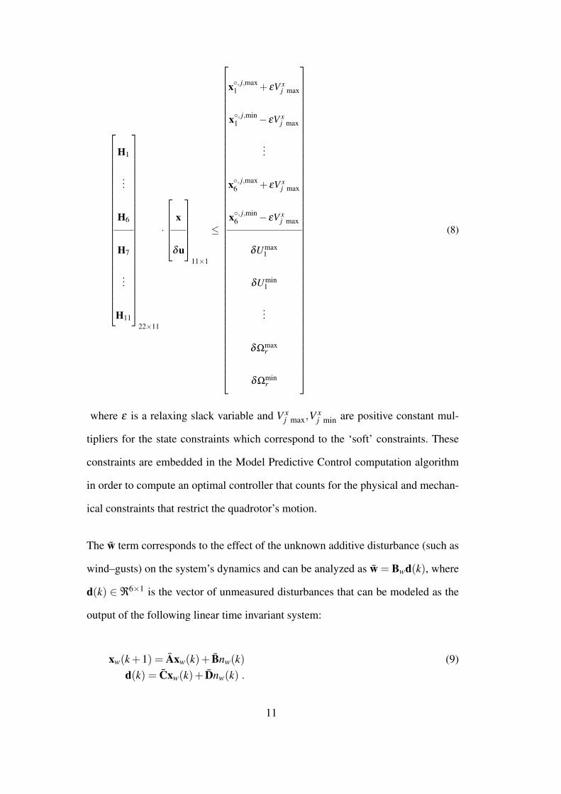
It should be emphasized that the ad–hoc parameters’ selection for the prediction
and control horizon, (p, m) = (10,2), that have been utilized in the formulation
of the MPC–cost (10) have not been the optimal ones, as highlighted in Figure 15,
where the achieved MSE for the adopted SMPC is depicted for various p, m param-
eters; the optimal parameter–pair corresponds to (p,m) = (14,4). Since the compu-
tational burden monotonically increases with p and m, smaller values are generally
preferred; however in general these small values typically lead to an excitation of
the high frequency harmonics and the quadrotor’s response oscillates significantly.
25
2
3
4
5
6
10
12
14
16
18
20
2
4
6
8
x 10−3
m
p
MSE
(rad
2 )
Fig. 15. SMPC Performace w.r.t. various p and m Parameters
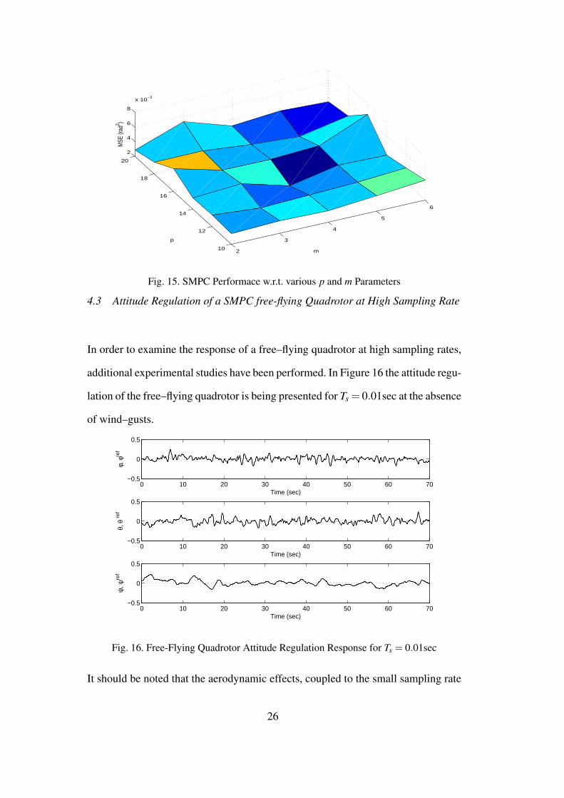
4.3 Attitude Regulation of a SMPC free-flying Quadrotor at High Sampling Rate
In order to examine the response of a free–flying quadrotor at high sampling rates,
additional experimental studies have been performed. In Figure 16 the attitude regu-
lation of the free–flying quadrotor is being presented for Ts = 0.01sec at the absence
of wind–gusts.
0 10 20 30 40 50 60 70−0.5
0
0.5
Time (sec)
φ, φ
ref
0 10 20 30 40 50 60 70−0.5
0
0.5
Time (sec)
θ, θ
ref
0 10 20 30 40 50 60 70−0.5
0
0.5
Time (sec)
ψ, ψ
ref
Fig. 16. Free-Flying Quadrotor Attitude Regulation Response for Ts = 0.01sec
It should be noted that the aerodynamic effects, coupled to the small sampling rate
26
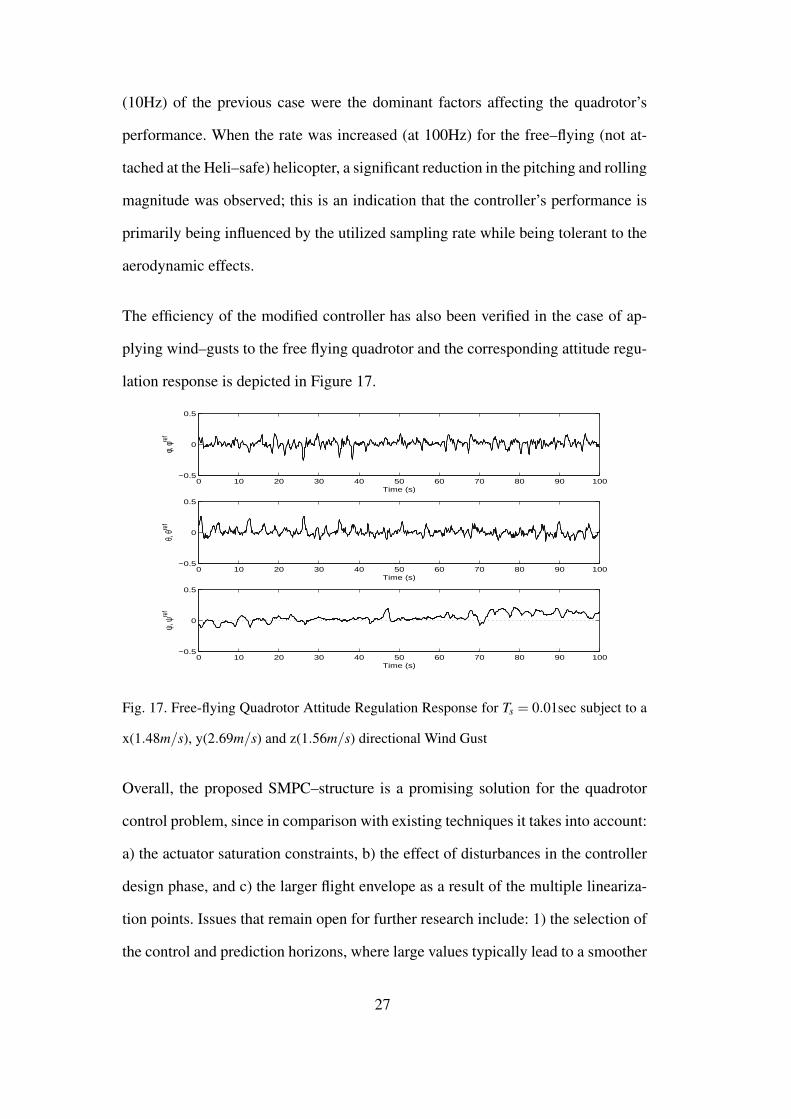
(10Hz) of the previous case were the dominant factors affecting the quadrotor’s
performance. When the rate was increased (at 100Hz) for the free–flying (not at-
tached at the Heli–safe) helicopter, a significant reduction in the pitching and rolling
magnitude was observed; this is an indication that the controller’s performance is
primarily being influenced by the utilized sampling rate while being tolerant to the
aerodynamic effects.
The efficiency of the modified controller has also been verified in the case of ap-
plying wind–gusts to the free flying quadrotor and the corresponding attitude regu-
lation response is depicted in Figure 17.
0 10 20 30 40 50 60 70 80 90 100−0.5
0
0.5
Time (s)
φ, φre
f
0 10 20 30 40 50 60 70 80 90 100−0.5
0
0.5
Time (s)
θ, θre
f
0 10 20 30 40 50 60 70 80 90 100−0.5
0
0.5
Time (s)
ψ, ψ
ref
Fig. 17. Free-flying Quadrotor Attitude Regulation Response for Ts = 0.01sec subject to a
x(1.48m/s), y(2.69m/s) and z(1.56m/s) directional Wind Gust
Overall, the proposed SMPC–structure is a promising solution for the quadrotor
control problem, since in comparison with existing techniques it takes into account:
a) the actuator saturation constraints, b) the effect of disturbances in the controller
design phase, and c) the larger flight envelope as a result of the multiple lineariza-
tion points. Issues that remain open for further research include: 1) the selection of
the control and prediction horizons, where large values typically lead to a smoother
27

yet slower response, 2) the selection of the number for the utilized PWA–models,
the appropriate linearization operating points and the bounds for each region, 3)
the need to have an accurate knowledge of the quadrotor dynamics, 4) the effect
the noise and/or bias in the measurements,since these may affect the performance
of the EKF, and 5) the assumption of a white–noise kernel for the induced wind–
gust.
5 Conclusions
In this paper, a Switching Model Predictive Controller for an Unmanned quadro-
tor Helicopter flying in an environment at the presence of wind–gusts has been
presented. The main contribution of the proposed control scheme includes the de-
velopment of a model predictive controller, for the set of the induced linearized
Piecewise Affine models of the system. The PWA–approximations cover a larger
subset of the quadrotor’s flight envelope, and the controller takes into account the
physical constraints of the system. Finally the controller has been experimentally
shown sufficient robustness against wind–gust disturbances, whose bounds have
been utilized for the off–line computation of the controller. The presented experi-
mental results indicate the high overall efficiency of the proposed SMPC–scheme
in attitude maneuvers tracking, with wind–gust disturbance attenuation.
References
Alexis, K., Nikolakopoulos, G., Tzes, A., 2010a. Constrained optimal attitude con-
trol of a quadrotor helicopter subject to wind–gusts: Experimental studies. In:
28

2010 American Control Conference, pp. 4451-4455, June 30 - July 2, Baltimore,
USA.
Alexis, K., Nikolakopoulos, G., Tzes, A., 2010b. Design and experimental verifi-
cation of a constrained finite time optimal control scheme for the attitude control
of a quadrotor helicopter subject to wind gusts. In: 2010 International Confer-
ence on Robotics and Automation, pp. 1636-1641, May 3-8, Anchorage, Alaska,
USA.
Guerrero-Castellanos, J. F., Marchand, N., Hably, A., Lesecq, S. and Delamare,
J., 2011. Bounded attitude control of rigid bodies: Real-time experimenta-
tion to a quadrotor mini-helicopter. In Control Engineering Practice (In press),
doi:10.1016/j.conengprac.2011.04.004.
Alexis, K., Nikolakopoulos, G., Tzes, A., 2010c. Model Predictive Control for
a Miniature Coaxial Helicopter. In: 7th IFAC Symposium on Intelligent Au-
tonomous Vehicles, article #16094, vol. 7, no. 1, September 6-8, Lecce, Italy.
Alexis, K., Nikolakopoulos, G., Tzes, A., Dritsas, L., June 2009. Coordination of
helicopter UAVs for aerial Forest-Fire surveillance. In: Applications of Intelli-
gent Control to Engineering Systems. Springer Netherlands, pp. 169–193.
S. Bouabdallah, 2007. Design and Control of quadrotors with application to au-
tonomous flying, Ph.D. dissertation, EPFL STI School of Engineering 2007.
Lausanne, Switzerland.
Bouabdallah, S., Becker, M., Siegwart, R., 2007. Autonomous miniature flying
robots: coming soon! - research, development, and results. In IEEE Robotics
& Automation Magazine, 14 (3), 88–98.
Bouabdallah, S., Noth, A., Siegwart, R., 2004. PID vs LQ control techniques ap-
plied to an indoor micro quadrotor. In: Proceedings of the IEEE/RSJ Interna-
tional Conference on Intelligent Robots and Systems, pp. 2451–2456, September
28 - October 2, Sendai, Japan.
29
Bouabdallah, S., Siegwart, R., 2007. Full control of a quadrotor. In: 2007 IEEE/RSJ
International Conference on Intelligent Robots and Systems. pp. 153-158, Octo-
ber 29 - November 1, San Diego, CA, USA,
Bristeau, P-J., Martin, P., Salaun, E., and Petite N., 2009. The Role of Propeller
Aerodynamics in the Model of a Quadrotor UAV, In European Control Confer-
ence, pp. 683-688, August 23-26, Budapest, Hungary.
Costello, M. F., 1992. A theory of the analysis of rotorcraft operation in atmo-
spheric turbulence. Ph.D. dissertation, School of Aerospace Engineering, Geor-
gia Institute of Technology.
Drela M. 1989, XFOIL: an analysis and design system for low Reynolds number
airfoils. In: Mueller TJ, Editor. Low Reynolds numbers aerodynamics, Lecture
Notes in Engineering, vol. 54. pp. 1-12, New York: Springer, 1989.
Bristeau, P.-J., Dorveaux, E., Vissiere, D., Petit, N., 2010. Hardware and software
architecture for state estimation on an experimental low-cost small-scaled heli-
copter. In Control Engineering Practice, vol. 18, No. 7., pp. 733–746.
Pounds P., Mahony R., and P. Corke 2010. Modelling and control of a large quadro-
tor robot. In: Control Engineering Practice, Special Issue on Aerial Robotics, vol.
18, pp. 691-699.
Hoffmann, G. M., Huang, H., Waslander, S. L., Tomlin, C. J., 2007. Quadrotor
helicopter flight dynamics and control: Theory and experiment. In: Proc. of the
AIAA Guidance, Navigation, and Control Conference, article 6461, August 20-
23, Hilton Head, SC, USA.
Kondak, K., Bernard, M., Meyer, N., Hommel, G., 2007. Autonomously flying
VTOL-Robots: modeling and control. In: 2007 IEEE International Conference
on Robotics and Automation. pp. 736–741, April 10-14, Rome, Italy
Lukianto C., Honniger C, Sternberg H., 2010, Pedestrian Smartphone-Based In-
door Navigation Using Ultra Portable Sensory Equipment. In: Proceedings of
30

the IEEE 2010 International Conference on Indoor Positioning and Navigation,
pp. 1-5, September 15-17, Zurich, Switzerland.
Martini, A. and Leonard, F. and Abba, G. 2009. Dynamic Modelling and Stability
Analysis of Model-Scale Helicopters Under Wind Gust. In: Journal of Intelligent
Robotic Systems 2009, pp. 647–686, Kluwer Academic Publishers, Hingham,
MA, USA.
Merino, L., Caballero, F., Martinez, J., Ollero, A., 2005. Cooperative fire detection
using unmanned aerial vehicles. In Proceedings of the IEEE International Con-
ference on Robotics and Automation, pp. 1884–1889, April 18-22, Barcelona,
Spain.
Metni, N., Hamel, T., November 2007. A UAV for bridge inspection: Visual ser-
voing control law with orientation limits. Automation in Construction 17 (1),
3–10.
Moore, R., 1979. Methods and Applications of Interval Analysis. SIAM Bookmart,
Philadelphia.
Perhinschi M. G. 1998. A Model of Atmospheric Turbulence for Rotorcraft Simu-
lation and Analysis of Stability and Performance. In: 1998 AIAA Modeling and
Simulation Technologies Conference, pp. 635–642, Boston, MA, U.S.A.
Pounds P., Mahony R., and Corke P.,2006, Modelling and control of a quad-rotor
robot, Proceedings of the Australian Conference on Robotics and Automation,
December 6-8, Auckland, New Zealand.
Pounds P., Mahony R., and P. Corke 2010. Modelling and control of a large quadro-
tor robot. In: Control Engineering Practice, Special Issue on Aerial Robotics, vol.
18, pp. 691-699.
Raffo, G., Ortega, M., Rubio, F., 2010. An integral predictive/nonlinear control
structure for a quadrotor helicopter. Automatica 46 (1), 29 – 39.
Siagian C., Chang C-K., Voorhies R., Itti L. 2011. Beobot 2.0: Cluster architecture
31

for mobile robotics, In Journal of Field Robotics Volume 28, Issue 2, pp 278302.
Srinkanth M., Dydek Z., Annaswamy A., Lavretsky E., 2009. A Robust Environ-
ment for Simulation and Testing of Adaptive Control for Mini-UAVs. In Pro-
ceedings of the 2009 American Control Conference, pp. 5398-5403, June 10-12,
St. Louis, MO, USA.
Tayebi, A., McGilvray, S., 2006. Attitude stabilization of a VTOL quadrotor air-
craft. IEEE Transactions on Control Systems Technology 14 (3), 562–571.
Waslander, S. L., Hoffmann, G. M., Jang, J. S., Tomlin, C. J., 2005. Multi-agent
quadrotor testbed control design: Integral sliding mode vs. reinforcement learn-
ing. In: Proceedings of the IEEE/RSJ International Conference on Intelligent
Robotics and Systems, pp. 468–473, August 2-6, Edmonton, Alberta, Canada
Yang, X., Pota, H., Garrat, M., July 2009. Design of a gust–attenuation controller
for landing operations of unmanned autonomous helicopters. In: 18th IEEE In-
ternational Conference on Control Applications. Saint Petersburg, Russia, pp.
1300–1305.
32