Embed Size (px)
Citation preview

NATIONALr~m
ADVISORYCOMMITTEE‘aFORAERONAUTICS
TECHNICAL NOTE 3461
TURBULENT-HEAT-TRANSFERMEASUREMENTSAT
A MACHNUMBEROF 1.62
ByMauriceJ.BrevoortandBernardRashis
LangleyAeronauticalLaboratoryLangleyField,Va
WashingtonJune1955
https://ntrs.nasa.gov/search.jsp?R=19930084195 2018-05-27T21:05:35+00:00Z

TECHLIBRARYKAFB,NM
of
NATIONALADVISORYc(MMmTEE
TECENICfLNOTE
1!111[1111“FORAERONAU’TCCS 00bb57q”
3461
TUWUHNT-HEAl!-TRANSFER~ AT
A MACHNUIBEROF
ByMauriceJ.Brevoorts@
1.62
BernardhShiS
Turbulent-heat-transfermeasurementswereobtainedthroughtheuseau axialJ..Ysymmetricannularnozzlewhichcmsistsofan inner,shaped--
centerbcdyandan outercyltidricalsleeve.Measurementstaken~ong-theoutersleevegaveessentiallyfl-at-plateresultsthatarefreefromwallinterferenceandcornereffectsfora Machnrmiberof1.62andfora Reynoldsnuiberrangeof7.22x 10~to 1.20x 10⁸. Theheat-transfercoefficientsareingoodagreanentwiththeoretical.resultsfora WchnuuiberofI.60 * fora ratioof inner-surfaceto free-stresmtemper-
P atureof1.60. Thetemperature-recoveryfactorsareontheaverage1.~ percentlowerthanthefactorsobtainedfora Machnumberof2.4.
J
INTRODUCTION
Thedesignof supersonicaircraftandmissilesrequiresengineeringinformationaboutheat-transfercoefficientsandtemperature-recoveryfactorsforsuperscmicspeedsthatex%nd overa widersngeofReynoldsnlmiber● BIreferences1 and2,localturbulent-heat-transfermeasurementswerepresentedforI&chnumbersof3.03and2.06Jrespectively.
Thepurposeofthisinvestigationisto extendtheworkofrefer-ences1 and2,withthesametypeofapparatusandmethodofreduchgthedata,to a Machnuniberof1.62. ThersngeofReynoldsnmber forwhichmeasurementswereobtainedisfrom?.22x 105to 1.20x 10⁸. Theresultscovera temperaturedifferenceofapproxhately10oat 40 secondsafterstsrthgto a~roximately1°at 200secondsafterstarting.Theaveragevalueoftheratioof inner-surfacetemperatureto free-streamtemperatureT+~m was1.60.
2 NAC!ATN3461
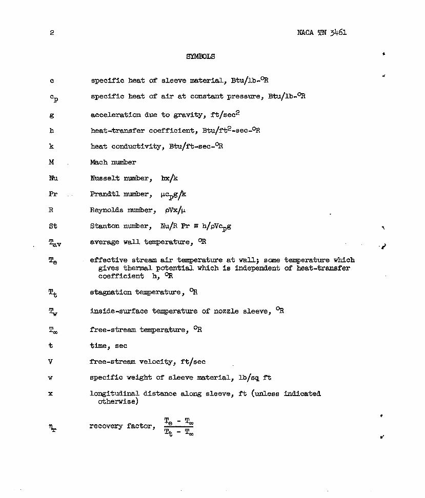
sYMmLs
c
%
~
h
k
M
Nil
Pr
R
St
‘rav
Te
%?
l!=
t
v
w
x
specificheatof sleevematerial,Btu/lb-%
specificheatofairat constantpressure,Btu/lb-%
accelerationdueto gravity,ft/sec2
heat-transfercoefficient,Btu/ft2-sec-%
heatconductivity,Btu/ft-sec-%
Mach?miber
IVusseltrnmiber,l+
Prandtlnuniber,W@
Reynoldsnwiber,pvx/p
Stantonnwiber,@R - = @J~g 7
averagewalltemperature,%‘2
effectivestreamairtemperatureatwall;sanetemperaturewhichgivesthermalpotentialwhichisindependentofheat-transfercoefficienth, %
stagnationtemperature,%
inside-surfaceteqeratureofnozzlesleeve,%
free-stresmtemperature,%
time,sec
free-streamvelocity,ft/sec
specificweightof sleevematerial,lb/sqft
longitudinaldistancealongsleeve,ft (unlessindicatedotherwise)
T - T@recoveryfactor,~
Tt - Tm

NACATN3461
ev dynamicviscositycoefficient,lb-sec/sqft
3
k P free-streamdensityofah, slugs/cu
APPARATUSAlil)METHOD
ft
Theapparatusconsistedofan axiallysymnetricannularnozzlewhichwasdirectlyconnectedto thesettlingcha?iberof oneofthecold-airblowdowzljetsoftheLangleygasdynamicskboratory.Thenozzlehada shapedwocdencenterbodyandtwooutersleeves.Onesleevewasconstructedof 8-inch-diameter,extraheavy,sesmlesscarbon-steelpipe,andtheotherwasconstructedofl/16-inchstainlesssteelwhichwasrolledintoa cylinderandwelded;bothcylindersweresurface-machinedinsideandoutsidetowsXLthicknessesof0.388inchand0.060inch,respectively.Thecoordinatesofthetier bodyaregivenintableI.
A detaileddrawingoftheapparatusis showninfigure1 whichgivesthelocationofthethermocouplesandstatic-pressureorifices.Detailsofthethermocouples,thestatic-pressure-orificeinstallations,
* thetemperature-recordingequilynent,andtheprecisionof instrumentationaregiveninreferences1 and2.
. TheWch nuniberdistributionis showninfigure2. Theal-inementoftheflowwascheckedat severalstationsby meansoforificeslocatedaroundthesleeve.Thelocationofthesemeasurementsis shownhfigure2.
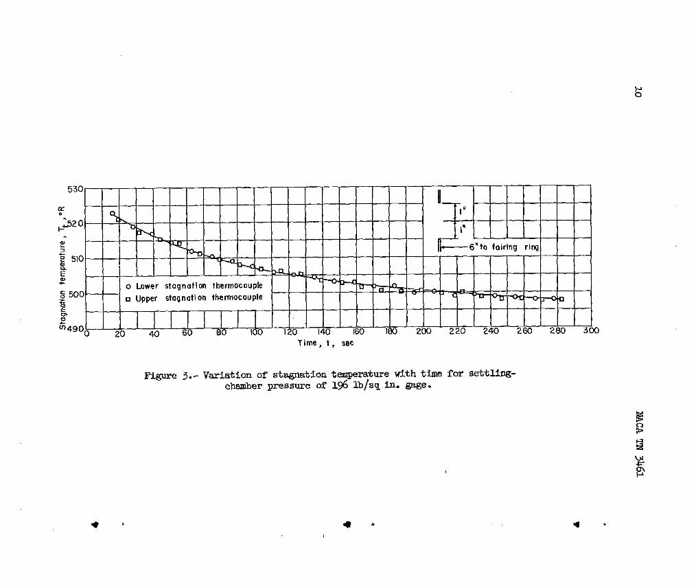
Thetestprocedureisgiveninreferences1 and2. Forthisinves-tigationtestrunsweremadeforsettli.ng-chauberpressuresof0.4,57,and196lb/sqin.gage. Thetestat a pressureof0.4Xb/sqin.gagewasmadewitha sleeve0.060inchthick,andthetestsetupwasevacuatedto an absolutepressureof1.0inchofmercury.Excludingthefirst20 seconds,thepressuresweremaintainedconstantforeachtestrun.Thestagnationtemperaturestwtedat essentiallyrocantemperatureanddecreasedasthepipingwascooled,as illustratedinfigure3 wherestagnationtemperatureisplottedagainsttimefora sett+g-chauiberpressureof 196lb/sqin.gage. Thewalltemperaturealsostartedatessentiallyrocmtemperatureandtendedto approachtheequilibriumtemperaturewhichwas approx5nately22°R beluwsta~tion temperate.Thisvariationis showninfigureh wherewaXLtemperatureat stations12and18 isplottedagainsttimefora settling-chsmiberpressureof196lb/sqin.gage.
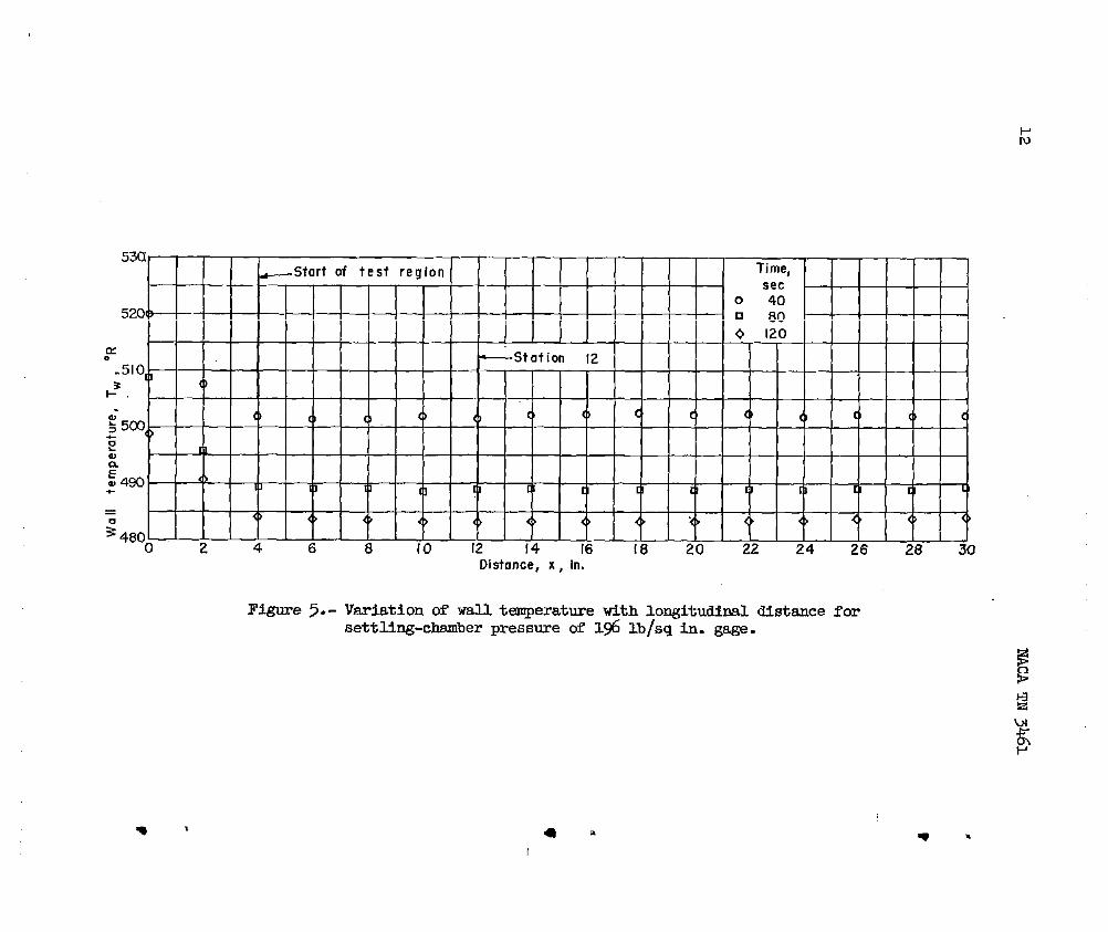
0 In figure~ areplotted,forvarioustimesdurx thetestrun,thevaluesofwalltemperatureagainstlongitudinaldistancealongthecylinder.Thesevalueswereusedto determinetherateofchangeof8
4
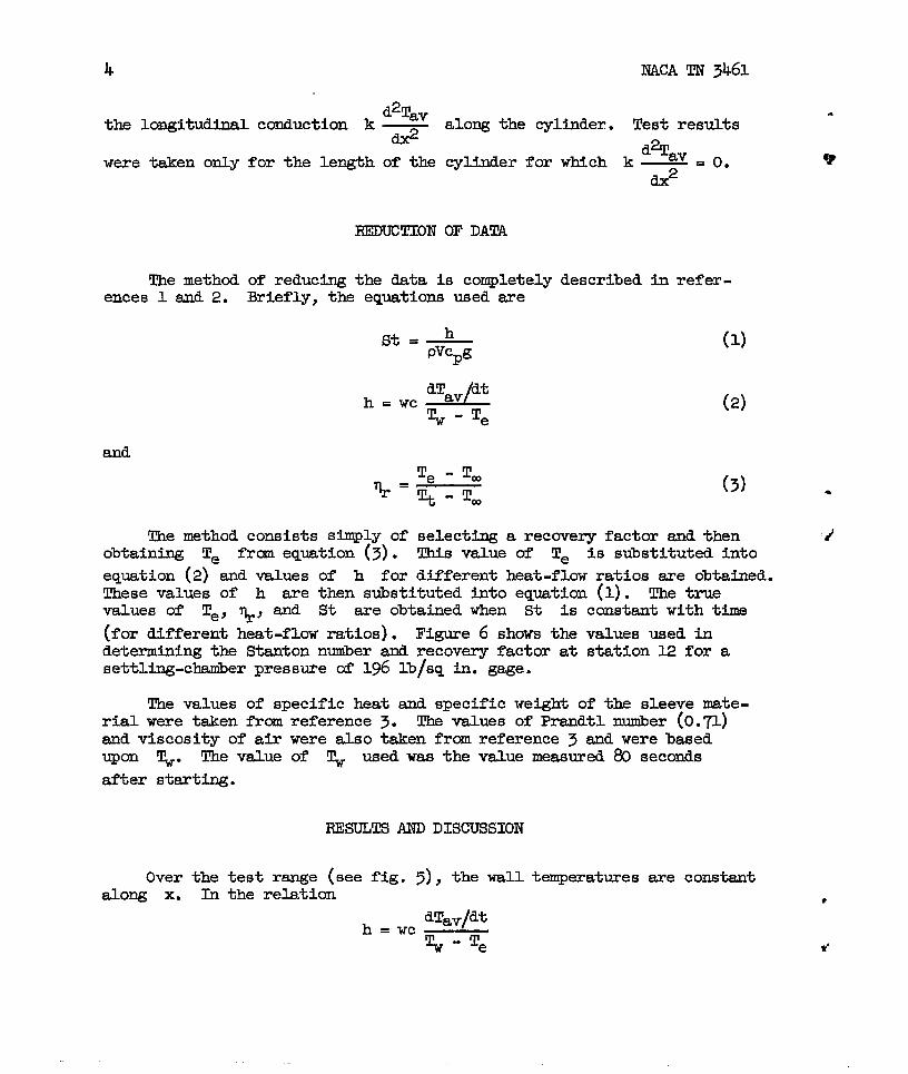
d2Tavthelongitudinalconductionk —
&weretakenonlyforthelengthofthe
REDUCTION
NACATN 3461
alongthecylinder.Testresults
cylinderfor
OFDATA
Themethodofreducingthedataiscompletelyences1 and2. Briefly,theequationsusedare
h ..c%L1~-Te
d%avwhich k —
d? ‘0”
describedinrefer-
(1)
(2)
(3)
Themethodconsistssimplyof selectinga recoveryfactorandthenobtainingTe frcmequation(3). Thisvalueof Te is stistitutedintoequation(2)andvaluesof h forclifferentheat-flowratiosareobtained.Thesevalues of h arethenstistitutedintoequation(l). Thetruevaluesof Te) ~~ and St areobtainedwhen St isconstantwithtime(fordifferentheat-flowratios).Figure6 showsthevalues usedindeterminingtheStantonnwber andrecoveryfactorat station12forasettling-chmiberpressureof196lb/sqin.gage.
Thevaluesof specificheatandspecificweightofthesleevemate-rialweretakenfromreference3. ThevaluesofPrandtlnuuiber(0.71)andviscosityofairwerealsotakenfromreference3 andwerebasedupon ~. Thevslueof ~ usedwasthevaluemeasured80secondsafterstarting.
RESULTSANDDISCUSSION
Overthetestrange(seefig.5), thewalltemperaturesareconstantalong x. Intherelation
*
1?
dTav/dth—.wc%-Te

NACATN 3461 5
. wandc areconstant,and dTav/dtisconstantbecauseTV is con-stant.Therefore,ifthereistobe a variationof h withReynolds
d’ numberor x, Z’emUSt VSXY with X. The valueof T= obtainedforthetestat a settling-chamberpressureoflg6lh/sqin.gage,evaluated80 seconds.afterstarting,actuallydecreasesabout1°.
Figure7 showsthevariationoflocalNusseltnumberwithlocalReynoldsnumber.Thevalueof x usedinevaluatingthesenumbershasbeenadjustedfor x = O locations(theeffectivebeginningofthetur-bulentboundarylayer)bythemethodofreferences1 and2. The x = Olocationsarek.o and1.0inchesdownstreamoftheminimumstationforsettlQg-chsmberpressuresof 0.4and57 lb/sqin.gage,respectively,andattheminimumstationforthesettling-chamberpressureof@ lb/sqin.gage.
TheNusseltnumberswerefoundto vary frm 84oto 56,650fortheReynoldsnumberrangeof 7.22x 10~to 1.20x 10⁸(basedonad~ustedx= O locations.)ForcomparisonthecurvebasedupontheVanDriestanalysis(ref.4) is shown.FortheVanDriestanalysis,Tw& WS
consideredto be 1.6o(theaveragevalue ofthetestresultspresentedm herein).
Thedatawerecomputedby usingfree-streamtemperatureto determine. thedensityandvelocity.Thewalltemperaturewasusedto determinethe
viscosityandthePrandtlnumber.Theagreementbetweenthetestresultsandthetheoryisgood.
Figure8 showsthevariationoflocaltemperature-recoveryfactorwithlocalReynoldsnmber. Thevariationisfrom0.880at 7.22x l@to 0.868at 1.2ox ld. Theresultsarecomparedwitha curvewhichrepresentsthefairingofthedataofreference5 fora Machnmnberof2.4. Theresultsobtainedinthisinvestigationareontheaverage1.5percentlowerthanthedataofreference5. Alsoincludedfor‘com-
1/3 and prl/2.parisonarethecurvesfortherecoveryfactorequl to PrThewalltemperaturewasusedto determinethePrandtlnumber.
.
d
6 NACATN 3461
CCINCLUDINGREMARKS.
vTurbulent-heat-transfermeasuremerrtsthatgaveessentiallyflat-
plateresultswereobtainedfora Machnumberof1.62andfora Reynoldsnumberrangeof 7.22x 10⁵to 1.20x 10⁸. TheNusseltmmibersagreewiththeoreticalresults.Thetemperature-recoveryfactorsareontheaver.age1.5percentlowerthanotheravailabledatafora Machnumberof2.4.
LangleyAeronauticalLaboratory,NationalAdvisoryCommitteeforAeronautics,
~ey Field,Vs.,lfarch~, 155.
REFIELENCES
1.Brevoort,MauriceJ.,andRashis,Bernard:Turbulent-HeatflransferMeasurementsat a MachNumberof3.03.NACATN3303,1954.
2.Brevocmt,MauriceJ.,andRashis,Bernard:Turbulent-Heat-TrensferMeasurementsat a MachNumberof2.06.NACATN 3374,1955.
3. Eckert,E.R. G. (WithAppendixby RobertM. Drake,Jr.): Introduc-tiontotheTransferofHeatandMass.Firstcd.,McGraw-HillBookCO. IU., l~o, PP. 266~ti 274.
4.VanDriest,E. R.: TheTurbulentBoundaryLayerforCompressibleFluidson a FlatPlateWithHeatTransfer.Rep.No.AL-997,NorthAmericanAviation,Inc.,Jan.27,1%0.
5. Staider,JacksonR.,Rubesin,MorrisW.,andTendeland,Thorval:ADeterminationoftheLsminar-,Transitional-,andTurbulent-Boundary-LayerTemperature-RecoveryFactorsona FlatPlatein SupersonicFlow. NACATN 2077,1%0.
r-.. .
.—
.
“

N.4CATN 3461 7
.
?
x, in.-10.00-4.70-4.%-4.00-3.00-2.50-2.00-1.X-1.00:::
-.40-.200
●10.20.30
TABLEI.- clm!m-BoDYcoommwlzs
Radius, in.2.0002.0002.0202*lm2.5002.7352.9703.1503.3003.3403●3753.4033.4253.43753.43643.43373.4298
t.x, in. Radius, in.0.442 3.4249
3.4190% 3.4L?2.70 3.4045●8O, 3.3961●9O 3.38~1.00 3.37761.10 3.36%1.20 3935a1.30 ;.344.1.40l.~ 3:33171.60 3.32381.70 3.31671.80 3.3103l.go [email protected] 392997
x, in.2.102.202.302.4Q2.502.602.702.802.905.00
10.CO15,0020.0025.00S.oo35.0038.625
Radius, in.3=9553.29203.28913.2%83.28513.28393.28313.28273.28253.27203.2k703.22203.19703.17203.14703.12203.1059

C2
\
‘ ‘5’,,\
u 59
Fcmr thermocouple at stntlcmsO, 6, 12, 18, 24, ad 30 s~ced90° awrt. One only at eochof the other %tlons. Totalnumber of t hermoccuples, 36,
One sleeve 0.388 wall thicknessOne sleeve O.O&l wall thickness
Siognatlon
I,-’,,
I
--L 1=f? J /’
-“~—T” 1- Z@
// ;:_J
P
ur pressure oflflces ot stationsMahogany O, 4, 11, 25, and 31 spaced 9cP
/,/ - “P“ Stationo center body apart. One only at each of the
other %tkms. Total number of—.!”... . .
/
\
L------47premm 0rIIIGe8, x..
+SettUnq ctmmbtr
Figure 1.- Test arrangement. IMnksnsionsare in hche~.
,
%“

1.80-c Start of test section
o.60 ~ 7 m l-cl v 9 u n n
un
u
o ●
O Single orifice
~ I .40 “c)
● Four orifices .
c 90” apart
xu o; 1.20
I .Oqj2468101214161820 222426283032
Distance, x, in.
Figure 2.- Mach number distributionfor settling-chsmberpressure of1* Mjsq in. gage.
E 1 1 I ! ,
m0
H]120 140 160 180 200 220 240 2W 280 3CQ
Time, t, sac
Figure 3.-Variation of stagndiontemperatwe with time for settling-chsmber pressure of 196 lb/sq in. gage.

● ✎
Time, t , sec
Figure 4.-Varlationofwalltemperatuxewith thue forpressure of l% lb/sq in. gage.
settling-chsmber
G
5
5
lx
0.5
a)
Eal490
.
; 48002 4 6 8 10 12 14 16 [8 20 22 24 26 28 30
Distonce, x , in.
Figure ~.- Variation of ~ temperaturewith longilndhml distanceforsettling-chamberpressure of lx lb/sq in. gage.

.00I2
cI Recovery
.0010 factor, qrG
() o 0,871L’ ❑ .868
; .0008 () 6 .866t1
I1r 1
;
~ .0006<}
&{>
(>
.0004<>
40 80 120 160 200Time, t, sec
Figure 6.-Stanton number as a function of %ime and recovery factor atstation 12 for settling-chamberpresmwe of 15 lb/sq in. gage.

Reynolds number, R
Figure 7.- Variation of local Nusselt number with local Reynolds nuuiberfor ad$mted locations of x = O. Viscosityand Rrandtl number deter-mined for wall temperatures.
T, .

L ,
n~ oQ Q)‘~‘ o0‘ >0
G, I I I . .
Iu.u ‘ .)v .J.!.!’.!’!I I
‘.82 3 45.68 10 20X107
Reynolds number, R
Figure 8.-Vsxiation of local,recovery factor with local Reynoldsnumber for adjusted locations of x = O. Viscosity determinedfor wall temperatures.
G


![G R a M M a R 1 [ 1-Parsing ]](https://img.pdfslide.us/doc/110x75/5695d34f1a28ab9b029d7b01/g-r-a-m-m-a-r-1-1-parsing-.jpg)