Embed Size (px)
Citation preview
Electrical and Electronic MeasurementsLecture 3: Electromechanical Instruments
Part 2: DC Ammeters and Voltmeters
Dr. Haitham El-Hussieny
Electronics and Communications EngineeringFaculty of Engineering (Shoubra)
Benha University
September 2018
Dr. Haitham El-Hussieny Electrical and Electronic Measurements 1 / 19
Lecture Outline:
1 DC Ammeters.
2 DC Voltmeter.
3 Ohmmeter.
Dr. Haitham El-Hussieny Electrical and Electronic Measurements 2 / 19
Table of Contents
1 DC Ammeters.
2 DC Voltmeter.
3 Ohmmeter.
Dr. Haitham El-Hussieny Electrical and Electronic Measurements 3 / 19
DC Ammeters:Ammeter Circuit:
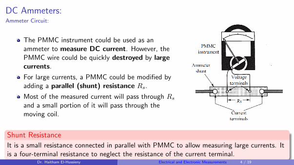
The PMMC instrument could be used as anammeter to measure DC current. However, thePMMC wire could be quickly destroyed by largecurrents.
For large currents, a PMMC could be modified byadding a parallel (shunt) resistance Rs.
Most of the measured current will pass through Rs
and a small portion of it will pass through themoving coil.
Shunt Resistance
It is a small resistance connected in parallel with PMMC to allow measuring large currents. Itis a four-terminal resistance to neglect the resistance of the current terminal.
Dr. Haitham El-Hussieny Electrical and Electronic Measurements 4 / 19
DC Ammeters:Ammeter Circuit:
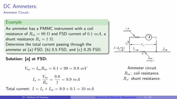
Example
An ammeter has a PMMC instrument with a coilresistance of Rm = 99 Ω and FSD current of 0.1 mA, ashunt resistance Rs = 1 Ω.Determine the total current passing through theammeter at (a) FSD, (b) 0.5 FSD, and (c) 0.25 FSD.
Solution: [a] at FSD:
Vm = ImRm = 0.1× 99 = 9.9 mV
Is =VmRs
=9.9
1= 9.9 mA
Total current: I = Is + Im = 9.9 + 0.1 = 10 mA
Ammeter circuitRm: coil resistance.Rs: shunt resistance.
Dr. Haitham El-Hussieny Electrical and Electronic Measurements 5 / 19
DC Ammeters:Ammeter Circuit:
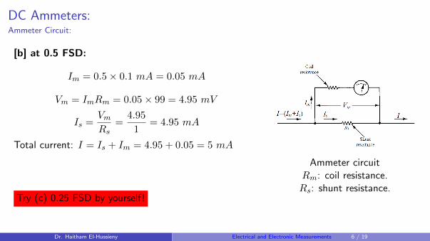
[b] at 0.5 FSD:
Im = 0.5× 0.1 mA = 0.05 mA
Vm = ImRm = 0.05× 99 = 4.95 mV
Is =VmRs
=4.95
1= 4.95 mA
Total current: I = Is + Im = 4.95 + 0.05 = 5 mA
Try (c) 0.25 FSD by yourself!
Ammeter circuitRm: coil resistance.Rs: shunt resistance.
Dr. Haitham El-Hussieny Electrical and Electronic Measurements 6 / 19
DC Ammeters:Shunt Resistance:
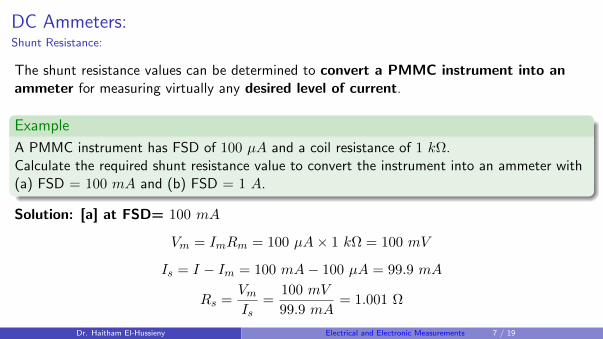
The shunt resistance values can be determined to convert a PMMC instrument into anammeter for measuring virtually any desired level of current.
Example
A PMMC instrument has FSD of 100 µA and a coil resistance of 1 kΩ.Calculate the required shunt resistance value to convert the instrument into an ammeter with(a) FSD = 100 mA and (b) FSD = 1 A.
Solution: [a] at FSD= 100 mA
Vm = ImRm = 100 µA× 1 kΩ = 100 mV
Is = I − Im = 100 mA− 100 µA = 99.9 mA
Rs =VmIs
=100 mV
99.9 mA= 1.001 Ω
Dr. Haitham El-Hussieny Electrical and Electronic Measurements 7 / 19
DC Ammeters:Shunt Resistance:
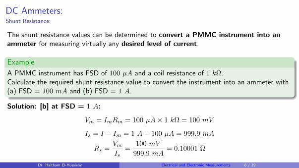
The shunt resistance values can be determined to convert a PMMC instrument into anammeter for measuring virtually any desired level of current.
Example
A PMMC instrument has FSD of 100 µA and a coil resistance of 1 kΩ.Calculate the required shunt resistance value to convert the instrument into an ammeter with(a) FSD = 100 mA and (b) FSD = 1 A.
Solution: [b] at FSD = 1 A:
Vm = ImRm = 100 µA× 1 kΩ = 100 mV
Is = I − Im = 1 A− 100 µA = 999.9 mA
Rs =VmIs
=100 mV
999.9 mA= 0.10001 Ω
Dr. Haitham El-Hussieny Electrical and Electronic Measurements 8 / 19
DC Ammeters:Swamping Resistance:
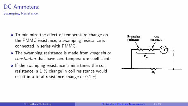
To minimize the effect of temperature change onthe PMMC resistance, a swamping resistance isconnected in series with PMMC.
The swamping resistance is made from magnain orconstantan that have zero temperature coefficients.
If the swamping resistance is nine times the coilresistance, a 1 % change in coil resistance wouldresult in a total resistance change of 0.1 %.
Dr. Haitham El-Hussieny Electrical and Electronic Measurements 9 / 19
DC Ammeters:Multirange Ammeter:
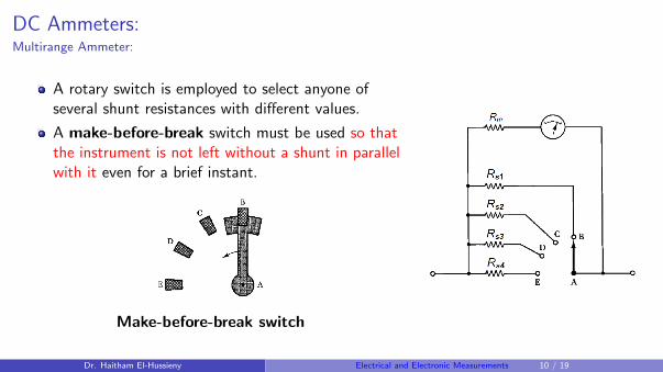
A rotary switch is employed to select anyone ofseveral shunt resistances with different values.
A make-before-break switch must be used so thatthe instrument is not left without a shunt in parallelwith it even for a brief instant.
Make-before-break switch
Dr. Haitham El-Hussieny Electrical and Electronic Measurements 10 / 19
Table of Contents
1 DC Ammeters.
2 DC Voltmeter.
3 Ohmmeter.
Dr. Haitham El-Hussieny Electrical and Electronic Measurements 11 / 19
DC Voltmeter:Voltmeter Circuit:
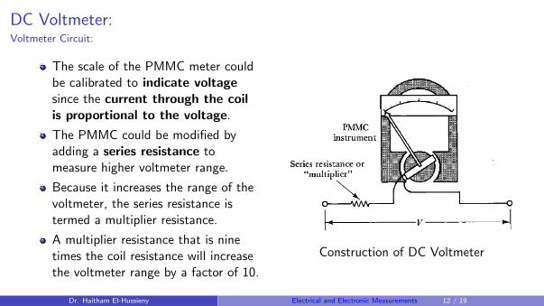
The scale of the PMMC meter couldbe calibrated to indicate voltagesince the current through the coilis proportional to the voltage.
The PMMC could be modified byadding a series resistance tomeasure higher voltmeter range.
Because it increases the range of thevoltmeter, the series resistance istermed a multiplier resistance.
A multiplier resistance that is ninetimes the coil resistance will increasethe voltmeter range by a factor of 10.
Construction of DC Voltmeter
Dr. Haitham El-Hussieny Electrical and Electronic Measurements 12 / 19
DC Voltmeter:Voltmeter Circuit:
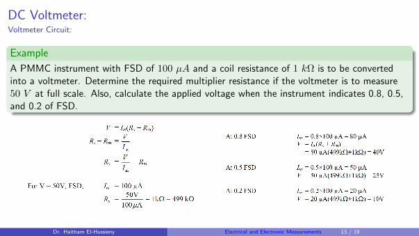
Example
A PMMC instrument with FSD of 100 µA and a coil resistance of 1 kΩ is to be convertedinto a voltmeter. Determine the required multiplier resistance if the voltmeter is to measure50 V at full scale. Also, calculate the applied voltage when the instrument indicates 0.8, 0.5,and 0.2 of FSD.
Dr. Haitham El-Hussieny Electrical and Electronic Measurements 13 / 19
DC Voltmeter:Voltmeter Sensitivity:
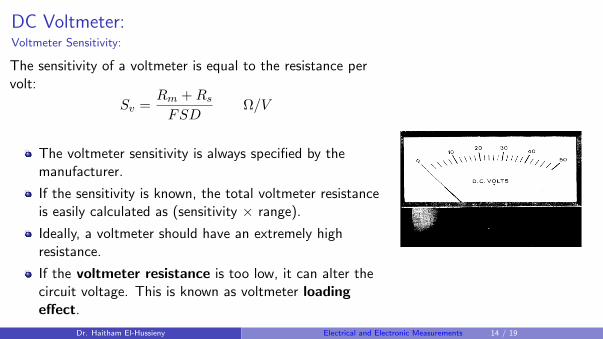
The sensitivity of a voltmeter is equal to the resistance pervolt:
Sv =Rm +Rs
FSDΩ/V
The voltmeter sensitivity is always specified by themanufacturer.
If the sensitivity is known, the total voltmeter resistanceis easily calculated as (sensitivity × range).
Ideally, a voltmeter should have an extremely highresistance.
If the voltmeter resistance is too low, it can alter thecircuit voltage. This is known as voltmeter loadingeffect.
Dr. Haitham El-Hussieny Electrical and Electronic Measurements 14 / 19
DC Voltmeter:Multirange Voltmeter:
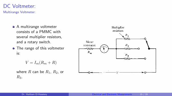
A multirange voltmeterconsists of a PMMC withseveral multiplier resistors,and a rotary switch.
The range of this voltmeteris:
V = Im(Rm +R)
where R can be R1, R2, orR3.
Dr. Haitham El-Hussieny Electrical and Electronic Measurements 15 / 19
Table of Contents
1 DC Ammeters.
2 DC Voltmeter.
3 Ohmmeter.
Dr. Haitham El-Hussieny Electrical and Electronic Measurements 16 / 19
Ohmmeter:Basic Circuit:
Series Ohmmeter:
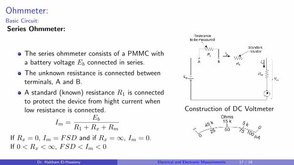
The series ohmmeter consists of a PMMC witha battery voltage Eb connected in series.
The unknown resistance is connected betweenterminals, A and B.
A standard (known) resistance R1 is connectedto protect the device from hight current whenlow resistance is connected.
Im =Eb
R1 +Rx +Rm
If Rx = 0, Im = FSD and if Rx =∞, Im = 0.If 0 < Rx <∞, FSD < Im < 0
Construction of DC Voltmeter
Dr. Haitham El-Hussieny Electrical and Electronic Measurements 17 / 19
Ohmmeter:Ohmmeter with Zero Control:
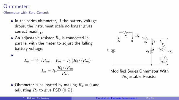
In the series ohmmeter, if the battery voltagedrops, the instrument scale no longer givescorrect reading.
An adjustable resistor R2 is connected inparallel with the meter to adjust the fallingbattery voltage.
Im = Vm/Rm, Vm = Ib.(R2//Rm)
Im = Ib.R2//Rm
Rm
Ohmmeter is calibrated by making Rx = 0 andadjusting R2 to give FSD (0 Ω).
Modified Series Ohmmeter WithAdjustable Resistor
Dr. Haitham El-Hussieny Electrical and Electronic Measurements 18 / 19
End of Lecture
Best Wishes
Dr. Haitham El-Hussieny Electrical and Electronic Measurements 19 / 19