Embed Size (px)
Citation preview

Mountz, IncISO 9001 (2000) company
P T TP T TPortable Torque Tester
Operating Instructions
2000

F e a t u r e s
System Accuracy +/- 0.5% of reading from 20% to 100% of full scale.System Accuracy +/- 1% of reading from 10% to 20% of full scale.Recommended for all hand screwdrivers, wrenches or power tools.Provides “EZ-Plug & Play” with Mountz Transducers. Features “ARCII” technology, an instant auto-recognition system of the transducer connected to the PTT. Selection of six operating modes: (Track, Peak, First Peak, Audit, Torque + Angle, and Tool Test).Seven units of torque measurements: (ozf.in, lbf.in, lbf.ft, cN.m, N.m, kgf.m, kgf.cm).Features built-in Tool Tests operation.Includes two PC Windows based software programs:PTT Interface Program- for sensor calibrations, meter calibration and tool tests,PTT Bootloader - for updating the PTT operating systems.Mountz Statics Calculator - for SPC, CP & CPK calculations.“Flash" memory allows upgrades to be done by the user in the field & internet through the USB port.Five low-pass filter selections (3000, 2000, 1500, 500 and 200 Hz).Easy to use Menu Structure.Real Time Clock for time stamping of readings.Six-digit display.USB interface to download readings to PC.High Capacity Li-Ion Batteries for long life (30 hrs with standard transducers and 16 hrs with brushless rotary).Can connect to most mv/v transducers and can store calibration data for up to 50 non smart torque sensors.The 5VDC capability allows unit to be used with a Brushless Rotary Transducer for testing pulse tools and high RPM tools.Torque and Angle readings are displayed simultaneously and supports up to 8000 RPM.Stores a total of 2500 data points.Real time graph of torque vs. time using associated PC Windows software. Features a Buzzer and Go / No Go LEDs that illuminate when high or low setting is achieved.Display Accuracy is better than +/- 0.0625 of reading.
Page 1
Heading PageExternal Connections 2User Interface 2Quick Menu Structure 3Screen Display 4Menu Selections 4Mode Selections 7Set-Up Selections 8Power On & Batter Operation 14Installation of PTT Interface Software 14Tool Test Operation 17Transducer Calibration 20PTT Calibration 21Data Logging (Graphing) 21Bootloader 23

U s e r I n t e r f a c e
Page 2
E x t e r n a l C o n n e c t i o n s
USBThe computer connection is USB. There is no setup required. This allows for data to downloaded to a PC. The PC willrequire a USB I/O.
External Transducer InputThe transducer connector is a high density D-Sub connector with 15 pins. The pin description is shown below:
Pin Number Function Description1 Analog Ground2 Brushless Signal Output from Brushless Transducer + /- 5V3 Not Used4 Sensor Direct Used to detect transducers5 Digital Ground6 Excitation Voltage + 5V or 16 volts depending on bridge or brush-less transducer7 Bridge Signal - Negative output from bridge transducer8 Not Used9 Angle Lead TTL output from angle detector in angle transducer
10 Sensor Drive Used to detect transducers11 Bridge Signal + Positive output from bridge transducer12 Shield13 Angle Trail TTL output for angle lags Angle Lead by 90 degrees14 +5 Volt Angle Supply15 Data for “Smart” Transducer Proprietary ARCII protocol for smart transducers from Mountz
Display ScreenDisplays the menu structures, torque readings, operating mode, torque units.
“Scroll and Enter Keys”Used to toggle through the different menu structures.
Function KeysFor selecting the following options: (Left to Right) Menu, Tool Tests & Cancel
Go and No Go LEDsUsed to monitor lower and upper torque limits and receive a visual warning.
Scroll Up
Scroll Right
Scroll Down
Scroll Left
Enter

Page 3
Q u i c k M e n u St r u c t u r e
Main Display Screen
Peak 1500 Hz
23.783 lbf.in
Menu
Filter Units Mode Setup
Main Menu
3000 Hz
2000 Hz
1500 Hz
500 Hz
200 Hz
ozf.in
lbf.in
lbf.ft
kgf.cm
kgf.m
N.m
cN.m
Track
Peak
First Peak
Audit
Torque & Angle
Tolerance
Auto Clear
Angle Threshold
T+A Threshold
First Peak
Direction
Clock
Sub-Menu
Sub-Menu
Sub-Menu
Sub-Menu
Enter Enter
Enter
Enter
Contrast
Page 4
S c r e e n D i s p l a y
When the Torque Analyzer is turned on and it is connected to a Mountz "Smart" Torque Transducer with ARCII technology it will display a Screen similar to that below for 5 seconds and then go into Reading Mode. This will also happen if a "Smart" transducer is disconnected and another smart transducer is connected.
Mountz PTT-2000Version 1.00f
Tool ModelBMX750i
Serial Number04-93-071
If an un-calibrated transducer is connected then the Analyzer will display a screen as below.
Note:The PTT supports Non-Smart transducers and Non-Mountz transducers. Non-smart transducers can bedetected and can be calibrated in the "internal" memory. The PTT will offer 2 choices. It offers to calibrate orchoose from a list of transducers stored in the internal memory.
Mountz PTT-2000Version 1.00f
Uncalibrated Transducer -Connect to Calibration Software
Note:When disconnecting a smart transducer and connecting another, the operator must unplug the cable from thePTT unit.

Page 5
R e a d i n g S c r e e n
Track 3000 Hz
+0.0000 Lbf.in
Menu Tool Tests
M e n u S e l e c t i o n s
Pressing the "Menu" Key will present the following Screen:1. Use the Scroll Up or Down key to toggle through:Filter, Units, Mode and Setup.2. Press Enter key to select a choice.
Filter
Units
Mode
Setup
1. Select Filter by highlighting and pressing Enter.2. Use the Scroll Up or Down key to toggle through the Filter options.3. Press Enter key to select a Filter Setting.
Filter
Units
Mode
Setup
3000 Hz2000 Hz1500 Hz500 Hz200 Hz
Selecting Filters
Main
Main Cancel
lbf.inlbf.ftozf.inkgf.cmkgf.mN.m
M e n u S e l e c t i o n s
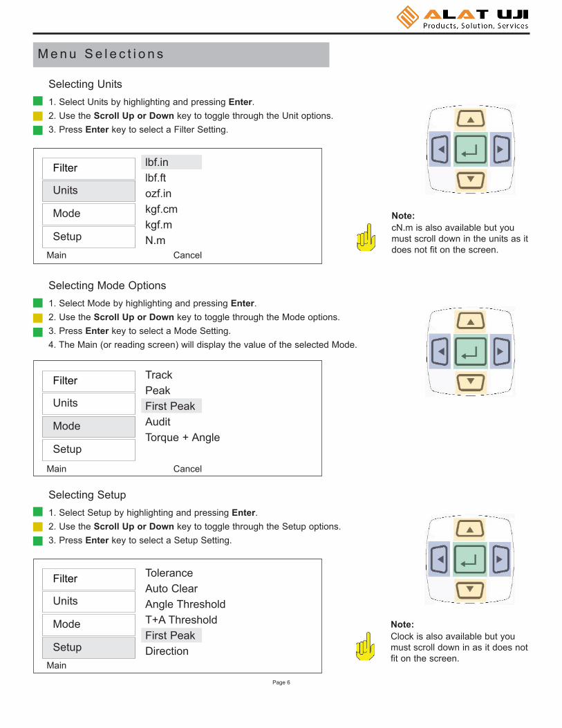
1. Select Units by highlighting and pressing Enter.2. Use the Scroll Up or Down key to toggle through the Unit options.3. Press Enter key to select a Filter Setting.
Filter
Units
Mode
Setup
Selecting Units
Note:cN.m is also available but youmust scroll down in the units as itdoes not fit on the screen.
TrackPeakFirst PeakAuditTorque + Angle
1. Select Mode by highlighting and pressing Enter.2. Use the Scroll Up or Down key to toggle through the Mode options.3. Press Enter key to select a Mode Setting.4. The Main (or reading screen) will display the value of the selected Mode.
Filter
Units
Mode
Setup
Selecting Mode Options
ToleranceAuto ClearAngle ThresholdT+A ThresholdFirst PeakDirection
1. Select Setup by highlighting and pressing Enter.2. Use the Scroll Up or Down key to toggle through the Setup options.3. Press Enter key to select a Setup Setting.
Filter
Units
Mode
Setup
Selecting Setup
Note:Clock is also available but youmust scroll down in as it does notfit on the screen.
Main Cancel
Main Cancel
Main
Page 6

M o d e S e l e c t i o n s
This mode constantly tracks increasing or decreasing torque variations. Use this mode to monitor varying torque on motorsand machinery. Also for calibration and testing of dial torque products (small wrenches or dial screwdrivers).
Track
Track 1500 Hz
+00.000 lbf.in
Menu Tool Tests
The display retains the highest torque applied. Use this mode during calibration or testing of any hand type torque wrench (dial, beam, and screwdriver), as well as power tools.
Peak
Peak 1500 Hz
+ 25.010 lbf.in
Menu Tool Tests
The display holds the first detected torque peak applied. Before anytorque is applied, the display show dashes in the torque value area.Once peak is detected, the display will show the torque value. If a second peak is detected then it will be displayed in the lower right (insmall reverse video).
This function is primarily used for testing and calibrating click typemechanical torque wrenches. The PTT captures the point where thewrench clicks. This peak may be used for operator training on correctuse of the wrench. Always apply torque smoothly to avoid false firstpeak readings.
See page 11 for setting up First Peak.
First Peak
FPK 3000 Hz
------- lbf.in
Menu Tool Tests
FPK 3000 Hz
5.4373 lbf.in
Menu Tool Tests+7.6261
This mode is used to determine “first movement” or what is commonlyknown as “break-away” torque to determine the actual torque on thejoint. An angle enabled transducer is required to operate in this mode.
See page 9 for setting up Angle Threshold.
Audit
Audit 1500 Hz
10.510 lbf.in
Menu Tool Tests
This allows an operator to set up an initial torque and follow up with arotation to a specified angle and display the final torque.
The PTT can collect Torque and Angle data if the unit is connected to atransducer that includes the angle function. It is a "Real Time" anglefunction that can capture Torque and Angle up to 8000 RPM.
See page 10 for setting up Torque + Angle.
Torque + Angle
T+A 3000 Hz
9.9985 lbf.in 10 deg
Menu Tool Tests
Page 7
0.00

ToleranceAuto ClearAngle ThresholdT+A ThresholdFirst PeakDirection
S e t u p S e l e c t i o n s
The Tolerance parameters control the Go and No-Go signal response (see Go / No Go Signal section). The user setsa lower and upper torque thresholds to get a visual and audible warning signals when these limits are reached orbreached during operation. This function is primarily used for safety and quality control.
Tolerance
Tolerance Setting
Low: _0.000 lbf.inHigh: 84.950 lbf.in
Main
1. Press the "Menu" Button. 2. Use the Scroll Down key and select Setup by highlighting and pressing Enter.3. Use the Scroll Up or Down key to toggle through the Setup options.4. Press Enter key to select a setup setting for Tolerance.
Filter
Units
Mode
Setup
Selecting Tolerance
1. Press the Right or Left key to toggle between High and Low Tolerance..2. Use the Scroll Up or Down key to change the tolerance settings .3. Press Enter key once setting is complete.4. Press Main button to return to main display screen.
This function controls the method of clearing the display of torque readings.
Auto ClearWhen Auto Clear is selected, the torque values, during operation, will automatically be cleared from the display.The user can set the time threshold to control how long the values should be displayed before clearing.
Manual ClearWhen Manual Clear is selected, the torque values during operation will indefinitely be display until the user pressesthe Clear key.
Clear
Page 8

ToleranceAuto ClearAngle ThresholdT+A ThresholdFirst PeakDirection
Auto Clear Setting
Mode: AutoTime (seconds): 2
Main
1. Press the "Menu" Button. 2. Use the Scroll Down key and select Setup by highlighting and pressing Enter.3. Use the Scroll Up or Down key to toggle through the Setup options.4. Press Enter key to select a setup setting for Auto Clear.
Filter
Units
Mode
Setup
Selecting Clear
1. Use the Scroll Up or Down key to toggle between Manual or Auto Clear.2. Press the Scroll Left or Right key to move down to the Time selection3. For Auto Clear, use the Scroll Up or Down key to toggle between the selection
of time between 1- 5 seconds.4. Press Enter key once setting is complete.5. Press Main button to return to main display screen.
ToleranceAuto ClearAngle ThresholdT+A ThresholdFirst PeakDirection
This is for the Audit mode. The default setting is 2 degrees, but it can be set from 1 to 5 degrees.
Angle Threshold
1. Press the "Menu" Button. 2. Use the Scroll Down key and select Setup by highlighting and pressing Enter.3. Use the Scroll Up or Down key to toggle through the Setup options.4. Press Enter key to select a setup setting for Angle Threshold.
Filter
Units
Mode
Setup
Selecting Angle Threshold
Page 9

Angle Threshold
Angle Threshold: 2 deg
Main
1. Use the Scroll Up or Down key to toggle through the degree values (0.25-5)It move at increments of 0.25
2. Press Enter key once setting is complete.3. Press Main button to return to main display screen.
Page 10
ToleranceAuto ClearAngle ThresholdT+A ThresholdFirst PeakDirection
This allows an operator to set up an initial torque and follow up with a rotation to a specified angle and display thefinal torque.
Torque + Angle
Torque+Angle Thresh
Angle: 2.00 degTorque: 50.000 lbf.inAllow Ratchet: NoMain
1. Press the "Menu" Button. 2. Use the Scroll Down key and select Setup by highlighting and pressing Enter.3. Use the Scroll Up or Down key to toggle through the Setup options.4. Press Enter key to select a setup setting for Torque + Angle.
Filter
Units
Mode
Setup
Selecting Torque + Angle
1. Press the Right or Left key to toggle between the three settings: Angle, Torque Allow Ratchet
2. Use the Scroll Up or Down key to set Angle (increments of 0.25)3. Use the Scroll Up or Down key to set Torque (increments of 0.5)4. Use the Scroll Up or Down key to set “Yes” or “No” for allowing ratchet*.5. Press Enter key once setting is complete.6. Press Main button to return to main display screen.
* Note - “Yes” allows for ratcheting the wrench back without accumulating angle.

ToleranceAuto ClearAngle ThresholdT+A ThresholdFirst PeakDirection
The display holds the first detected torque peak applied. Before any torque is applied, the display show dashes in thetorque value area. Once peak is detected, the display will show the torque value. If a second peak is detected then it will be displayed in the lower right (in small reverse video).
First Peak
First Peak Setup
Sensitivity: LowMin Peak: 5.0089 Lbf.in
Main
1. Press the "Menu" Button. 2. Use the Scroll Down key and select Setup by highlighting and pressing Enter.3. Use the Scroll Up or Down key to toggle through the Setup options.4. Press Enter key to select a setup setting for First Peak.
Filter
Units
Mode
Setup
Selecting First Peak
1. Use the Scroll Up or Down key to toggle through the sensitivity settings: (Low, Medium & High)
2. Press the Right or Left key to move down to the Min Peak setting location3. Use the Scroll Up or Down to set the Minimum Peak4. Press Enter key once setting is complete.5. Press Main button to return to main display screen.
Page 11
Note:First Peak Sensitivity
This feature is provided for click wrenches. It is not relevant for Mountz Break-overor Cam-over products such as MMTB, TB, TBIH, MTBN, TSN, TSP, and TSC.
High sensitivity will clearly display the "double" peak produced by a click wrench.Low sensitivity will reduce "false peaks" caused by operator hesitation.
For most click wrenches try using Medium sensitivity this works for many types ofclick wrenches such as the Mountz Titan and DM wrenches. As different types ofclick wrenches differ in how quickly they move from a first peak (click) to a secondpeak (over torque). Some experimentation, with sensitivity, may be required inorder to get repeatable results.

ToleranceAuto ClearAngle ThresholdT+A ThresholdFirst PeakDirection
Allows an operator to set the direction for capturing the torque readings: (Clockwise, Counter Clockwise and Bothdirections).
When performing a dead weight calibration, the direction should be set for both directions.
Direction
Direction Setting
Direction: BOTH
Main
1. Press the "Menu" Button . 2. Use the Scroll Down key and select Setup by highlighting and pressing Enter.3. Use the Scroll Up or Down key to toggle through the Setup options.4. Press Enter key to select a setup setting for Direction.
Filter
Units
Mode
Setup
Selecting Direction
1. Use the Scroll Up or Down key to toggle through the dIrection settings: (Both, CW, CCW)
2. Press Enter key once setting is complete.3. Press Main button to return to main display screen.
Page 12

Page 13
The PTT provides “EZ-Plug & Play” with Mountz Transducers that feature “ARCII” technology, an instant auto-recognition system of the transducer connected to the PTT. When an ARCII Transducer is connected to the PTT itautomatically recognizes the transducer and displays the Model and Serial Number of the connected transducer onthe PTT.
The information stored in the ARCII chips contains:
The Model of Transducer The Serial Number of the TransducerTrue Calibration InformationDate of Calibration
Auto ClearAngle ThresholdT+A ThresholdFirst PeakDirectionClock
Clock Setting
2:57 PM11/15/05
Main
1. Press the "Menu" Button. 2. Use the Scroll Down key and select Setup by highlighting and pressing Enter.3. Use the Scroll Up or Down key to toggle through the Setup options.4. Press Enter key to select a setup setting for Clock.
Filter
Units
Mode
Setup
Selecting Clock
1. Use the Scroll Up or Down key to toggle through the digits for the date and time.*
2. Use the Right and Left key to move through the time and date sections.3. Press Enter key once setting is complete.4. Press Main button to return to main display screen.
Note:Must toggle through the first “time digits” to change from AM to PM.
Six months from the date of the transducer’s calibration a message will appear on the screen informing the operator it has been six months since the date of calibration. At this point the operator can pull the Transducer out ofservice or decide to continue to use it. After the initial message the user will be reminded one a month.
T r a n s d u c e r C a l i b r a t i o n R e m i n d e r
A R C I I ( A u t o R e c o g n i t i o n C h i p )
Page 14
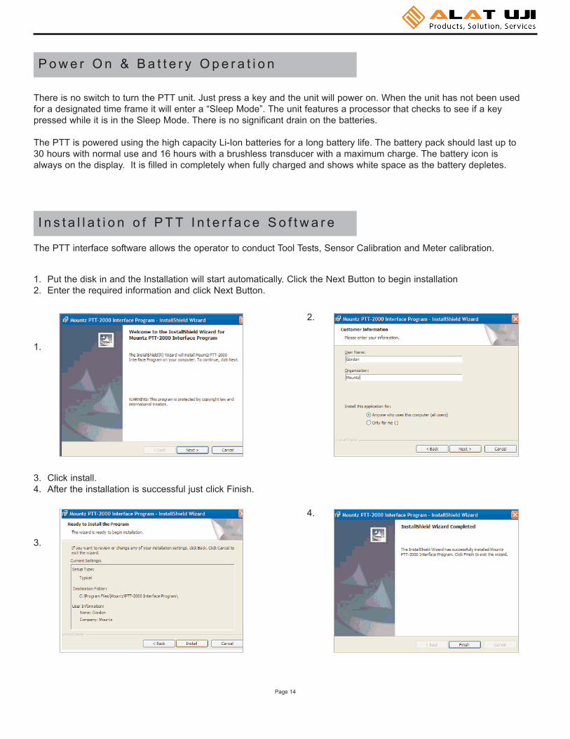
The PTT interface software allows the operator to conduct Tool Tests, Sensor Calibration and Meter calibration.
1. Put the disk in and the Installation will start automatically. Click the Next Button to begin installation2. Enter the required information and click Next Button.
1.
2.
3. Click install.4. After the installation is successful just click Finish.
3.
4.
I n s t a l l a t i o n o f P T T I n t e r f a c e S o f t w a r e
There is no switch to turn the PTT unit. Just press a key and the unit will power on. When the unit has not been usedfor a designated time frame it will enter a “Sleep Mode”. The unit features a processor that checks to see if a keypressed while it is in the Sleep Mode. There is no significant drain on the batteries.
The PTT is powered using the high capacity Li-Ion batteries for a long battery life. The battery pack should last up to30 hours with normal use and 16 hours with a brushless transducer with a maximum charge. The battery icon isalways on the display. It is filled in completely when fully charged and shows white space as the battery depletes.
P o w e r O n & B a t t e r y O p e r a t i o n

Page 15
6. Shortly after the PTT is detected the following screen will appear. Do not allow Windows to search for software. Click "No, not this time".
7. The CD should still be inserted from the installation, but if not insert it. Click "Install from a list or specific location" and click Next Button.
6. 7.
8. Check the "Search removable media" box and click Next Button.9. The USB drivers will begin to be installed. If a pop up window appears that the product has not passed the
Windows Logo Testing, just click "Continue Anyway". Mountz has tested the product with both the Home version and Professional version of XP. You will not get this message if you are installing under Windows 2000.
8. 9.
10.The initial screen will appear The "Online" LED should be green and Torque values are displayed on the right side of the screen. For most users the only Tab that will be used is the "Tool Tests". The other Tabs are used for Transducer and Meter calibrations, which should only be done by a certified calibration lab.
5. After installation of the PTT Interface Program turn on the PTT unit. Connect the USB cable to the PTT. and connect the other end to the computer. The computer detects the device in the lower right side of the screen.

Page 16
10.The initial screen will appear The "Online" LED should be green and Torque values are displayed on the right side of the screen. For most users the only Tab that will be used is the "Tool Tests". The other Tabs are used for Transducer and Meter calibrations, which should only be done by a certified calibration lab. Image below is “TorqueCalibration” screen.
11. Image below is “Meter Calibration” screen.

Page 17
12.The Tool Test Screen is below.
The Tool Test mode contains the follow fields.
A. Test NameB. Sensor ModelC. Tool Serial No.D. ModeE. UnitsF. FilterG. Low ToleranceH. High ToleranceI. Auto-Clear Mode
J. Auto-Clear TimeK. DirectionL. CommentsM. OperatorN. First Peak SensitivityO. Minimum First Peak (% of full scale)P. Audit Mode (Angle Threshold)Q. Torque and Angle Mode (Angle Threshold)R. Torque and Angle Mode (Torque Threshold)S. Torque and Angle Mode (Allow Angle Ratchet)
To o l Te s t O p e r a t i o n
All tool tests must be entered using the PC Windows based Calibration Program. Once this is done the tests can beaccessed using the "Tool Test" soft key on the PTT.
Entering data for the Tool Test is done using the PC Windows based Calibration Program. See the Screen above.Select the “Tool Tests” tab. Enter the relevant information on this screen such as the Test Name, which is the name bywhich the test will be identified on the PTT. Then enter all required information on the screen because once the tool testis activated on the PTT no changes can be made with the units, tolerances or other information. There is a field for comments to include user specific information. The transducer being used for the Tool Test must be identified. This isdone to prevent a test being run on a transducer with an inappropriate range.
When entering the “Sensor Model” this must match exactly with the sensor identification that was used to identify thetransducer when it was calibrated. If you are not sure about how the transducer is identified, unplug the transducer fromthe PTT unit and plug it back in. Note - the Sensor Model identification appears on the PTT screen during the initialization.
There are various control buttons to perform operations with this program, these include:

Page 18
There are various control buttons to perform operations with this program, these include:
Save - Saves the Tool Test Setups on the PC so it can be used to run further tests in the future.
Open - Opens previously saved Tool Test Setups.
Send - Send a Tool Test to the PTT. It can store up to 100 tests with 25 readings or 25 tests with100 readings or anysimilar combination that does not exceed 2500 results
Delete Test in Meter - Deletes this specific test from the PTT. The operator will be asked for confirmation before theaction takes place.
Download Results - Retrieves the results of a tool test after it has been run. It will offer a change to add further notes tothe test at this point. The results will be saved in the PC in C:\PTT 2000\Tool Test Results\Operator Folder where the"Operator Folder" will be the name of the Operator entered in the upper portion of the Tool Test Screen. The results arestored in a .csv file which can be opened in Excel or using a text editor program, such a Notepad. The file name will bethe name given to the tool followed by the date and the time at which to test was started.
Clear Data in Meter - Clears the test data for this Tool Test in the PTT meter. Make sure to Download the Resultsbefore clicking this button. The operator will be asked for confirmation before the action takes place.

Page 19
Once 1 or more tool tests are sent to the PTT meter the operator can press the "Tool Test" soft key on the PTT andfollowing Menu choices will appear:
SelectStartStopClear Memory
Choose the function desired, from the menu list, by using the Up /Down keys and use Enter key to finalize the selectionhighlighted in reverse video.
Select is used to select the desired test from a list of tests that have been downloaded. When an operator selects thishe/she will view an introduction for 3 seconds that provide directions, and then this will display:
Choose Tool Test from List of available tests.
Use Up /Down keys to toggle between tests.
Use Enter to select test.
After the short introduction the operator will see the tool tests displayed and can select the desired test.
Start begins collecting test data. The tool name will be followed by a colon and then the number of data points collected.
Stop ends the test. This is required as some users may want to collect 10 data or others may want to collect 25 pointsor more.
Clear Memory allows the test points to be cleared in the meter itself. The operator will be asked for confirmation before the action takes place. Thisfunction should only be used if the readings havebeen downloaded to the PC or test data is invalid for some reason.
Once all desired tests are run the operator can return to the PC to download all Tool Tests stored in the PTT. During a particular test download theoperator will be given the opportunity to add further notes to the file stored on the PC.
An example of one Tool Test Result file is shown on the right.
There is an optional Excel Add-In included on thePTT CD to perform statistical analysis on the datafrom the tool test. It is located in the folder OptionalExcel Statistics Add-In. Follow the instructions in thereadme file, in this folder, to use this Add-In.
Using the Tool Tests on the PTT

Page 20
Transducer Calibration should only be performed by an operator with the necessary calibration wheels or arm and weightsets or by a calibration lab. Mountz offers calibration services to perform this function.
PTT calibrations are done in conjunction with a PC Windows based Calibration Program. The program is easy to useand guides the user through the calibration steps.
Once the program is started and connected to the PTT meter, a button "Start" is provided to start the calibration. All theneeded information must be entered in the appropriate text boxes. This includes information such as the Sensor Model,Serial Number, the Full Scale torque value, the units of calibration and the transducer type (Bridge or Brushless). Onceall required information is entered, the Start button is clicked, and its function changes to "Continue" as shown in figurebelow and procedural information will be given in the large text box. A 2-point calibration should work well in all butexceptional circumstances.
Once the calibration is complete the calibration data will be stored in a Mountz "Smart" transducer using the ARCII proto-col. For non-smart transducers calibration data will be stored in the PTT internal memory. A sophisticated error correction algorithm assures that the data written to and retrieved from memory is always correct.
Once the calibration is complete, Torque Values will be displayed in the Torque Window allowing for verification of cali-bration data points.
T r a n s d u c e r C a l i b r a t i o n

Page 21
This procedure is used to calibration the gain of the PTT to a high degree of accuracy. This allows all PTT to exhibit thesame accuracy with a Mountz "Smart" transducer as the meter that was used to perform the calibration.
The PTT Calibration requires special equipment. This equipment is available from Mountz for those that require it as anoptional item.
P T T C a l i b r a t i o n
D a t a L o g g i n g
This program is used for graphing the data. This feature can be utilized to evaluate and confirm torque specifications inboth production or R & D environments.
When the graph first appears you can enlarge it by clicking onthe Zoom-Box, which is the square box made up of dashedlines just to the right of the big arrow. Then drag the cursor tosurround the small graph and the view will expand the graph asshown

Page 22
The PTT interface program contains a Tab for Data Logging. The actual plot on the Screen is Torque vs. Time. If youhave an Angle enabled transducer the Torque and Angle data will be collected in a .csv file. The data collection beginswhen you click the "Start" button and ends when you click the same button which changes to "Stop" after the data collec-tion begins. The data is collected is available in:C:\Program Files\Mountz\PTT Interface Program\Streaming Data Files\"operator name"Where the "operator name" is the operator entered on the Data Logging Tab. If you use this function frequently youprobably will want to create a shortcut to this folder.
The .csv file can be opened using Excel. You can use Excel to plot this data in a variety of formats or by using otherWindows based tools of your choice. There is also an Excel Spreadsheet with a Macro as an example of Plotting Torqueand Angle. This is available on the PTT CD in the folder Excel Macro for Torque and Angle. Open this Excel file, high-light the Torque and Angle data, click the Graphing Icon that is on the spreadsheet, the Torque and Angle will be plottedfor you. If you have your own Torque and Angle data you can just replace the example data with your own, highlight itand click the Graphing Icon to plot it.
Angle Torque6 3.64
21 3.6236 3.63
137 4.34153 3.99167 4.05182 4.23196 4.30211 4.13225 3.74240 3.99254 4.32269 4.52283 4.31298 4.01313 4.18327 4.38342 4.23356 3.95371 3.74385 3.99400 4.13414 4.15429 4.19444 4.13458 3.88473 3.90488 4.09503 4.01517 3.77532 3.79547 4.31561 4.26576 4.22591 4.05605 3.91620 3.86
This Spreadsheet gives an example of Plotting Torque and AngleValues. Simply highlight the cells containing the values of Angle andTorque and click on the Graphing Icon above.
If you have collected Torque and Angle values, using the PTT DataLogging Program, you can use this Template to Plot Torque andAngle. Simply substitute your own values for those on the left.
The data is collected is available in:C:\Program Files\Mountz\PTT Interface Program\Streaming DataFiles\”operator name”Where the “operator name” is the operator entered on the DataLogging Tab. If you use this function often you probably will want tocreate a shortcut to this folder.
Page 23
B o o t l o a d e r
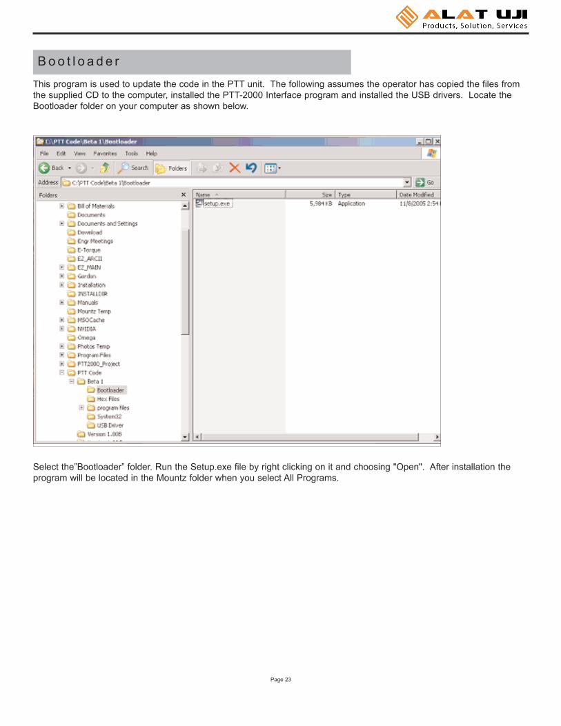
This program is used to update the code in the PTT unit. The following assumes the operator has copied the files fromthe supplied CD to the computer, installed the PTT-2000 Interface program and installed the USB drivers. Locate theBootloader folder on your computer as shown below.
Select the”Bootloader” folder. Run the Setup.exe file by right clicking on it and choosing "Open". After installation theprogram will be located in the Mountz folder when you select All Programs.

Page 24
The operator can put an icon on your desktop by right clicking on the PTT-2000 Bootloader and then "Send to" and'Desktop (create shortcut).
The icon will then be on the desktop. When the operator runs the program he/she will see a window as shown below.Connect the USB cable to the PTT and the computer and turn on the PTT unit. Click the button "Start boot loader ondevice". Both LED's on the PTT will turn on and the screen will indicate the PTT is in bootloader mode.
To update the firmware click the "Boot load HEX file to device.." button. Locate the HEX file update. It will be in theHex Files folder. The file is named Mountz App.hex. This is the current application so there is no need to update but ifthe operator chooses he/she can reload it to see how this feature works. The process will take about 6 minutes asthere is quite a lot of code in the product. The status will be shown in the PTT Boot Loader window as the processtakes place
As updates are available these will be available on the Mountz Web site.
Office: Jl. Radin Inten II No. 62 Duren Sawit, Jakarta 13440 - IndonesiaWorkshop: Jl. Pahlawan Revolusi No. 22B, Jakarta 13430 - IndonesiaPhone: 021-8690 6777 (Hunting)
Fax: 021-8690 6771Mobile: +62 816 1740 8925


![PTT Multicasting Scheme [호환 모드] · 2 New PTT Group Add by Mouse right button click 3PTTGrouppg Name Setting 4 PTT Group Number Setting 5 PTT Server Setting 6 PTT Group Session](https://img.pdfslide.us/doc/110x75/5f727989ade5745a8a06acb0/ptt-multicasting-scheme-eeoe-2-new-ptt-group-add-by-mouse-right-button.jpg)