Embed Size (px)
Citation preview
Automation of a 3-Phase AC Motor and Assembly Line Using Allen-Bradley MicroLogix 1000
Programmable Logic Controllers (PLCs)
Prepared by:
Steven M. Fuhrman
Faculty Advisors:
Scott Rausch
Interim Department Head/Instructor, Department of Electrical and Computer Engineering
Dr. Alfred Boysen
Professor, Department of Humanities
Program Information:
National Science Foundation
Grant NSF # EEC-1359476
Research Experience for Undergraduates
Summer 2015
South Dakota School of Mines & Technology
501 E. Saint Joseph Street
Rapid City, SD 57701
2
Table of Contents
Abstract ………………………………………………………………………………………… 3
Introduction ……………………………………………………………………………………... 3
Broader Impact …………………………………………………………………………………. 3
Procedure ………………………………………………………………………………………. 3
Materials ……………………………………………………………………………….. 3
Software/Equipment…………………………………………………………………….. 4
Procedures ……………………………………………………………………………… 4
Results ………………………………………………………………………………………….. 5
3-Phase Motor ………………………………………………………………………….. 5
Assembly Line …………...…………………………………………………………….. 5
Discussion ……………………………………………………………………………………… 7
Conclusion …………………………………………………………………………………...… 7
Appendices……………………………………………...……………………………………….. 8
Appendix A: Electrical Schematics …...……………………………………………….. 8
Appendix B: Images …………………………...…………………………………….... 13
Appendix C: Ladder Logic Code ……………………………………………………… 17
References …………………………………………………………………………………..… 20
Acknowledgments …………………………………………………………………………..… 20
3
Abstract
The automation of factory machines is commonly done using programmable logic controllers
(PLCs). Hands-on PLC training stations are helpful to train students how to use and program
PLCs. Two different PLC training setups have been designed, one automating a 3-phase AC
motor-generator set and the other automating a portion of an assembly line. Both of these
machines are automated using Allen-Bradley MicroLogix 1000 PLCs which have been
programmed with ladder logic control programs.
1. Introduction
Programmable logic controllers (PLCs) are widely used in industry for the industrial
automation of factory machines. To give students hands-on experience wiring and programming
PLCs, laboratory setups involving a 3-phase motor and an assembly line machine are designed.
Once these lab setups are built and tested PLC training labs will be developed so these setups can
be integrated into the laboratory curriculum at SDSM&T. For the automation of these machines
Allen-Bradley 1761-L20AWA-5A MicroLogix 1000 Analog PLCs will be used. The 3-phase
motor-generator set is being used as a test instrument that is relatively easy to understand and
work with. This electric machine consists of a 3-phase AC motor that drives a DC generator.
The PLC will be used to turn on and off the relay contactor which provides the AC power for the
motor. This test instrument will serve as a training and experimentation platform for learning
how to wire and program a PLC and to gain understanding about how each of its various types of
inputs and outputs work. The assembly line machine is an IC board component lead cutter that
was used in an assembly line in industry. The implementation of PLC control on this machine
makes for a perfect PLC training station as it demonstrates how a PLC can be used on an actual
machine from industry.
The Allen-Bradley 1761-L20AWA-5A MicroLogix 1000 Analog PLCs have 12 discrete
AC inputs and 8 AC/DC outputs. The inputs will be used to read the position of a switch and the
outputs are used as relays which are programmatically energized and de-energized. They also
have two analog voltage inputs, two analog current inputs and one analog output that can be
configured as an analog voltage or current output. The goal in the control programs and wiring
is to make use of as many of the different types of inputs and outputs as possible. This is to
demonstrate the many capabilities of this PLC and to give students practice using all them.
2. Broader Impact
The broader impact of this project is to have effective laboratory setups for the hands on
teaching of PLCs. Both the 3-phase motor and assembly line machine will be used as PLC
training instruments used in multiple classes at SDSM&T. The assembly line machine rewired
for PLC control provides for an effective training instrument to train students how to properly
wire and program a PLC while at the same time using an actual machine from industry. This
will better prepare students who want to work in the industrial automation field.
3. Procedure
Materials
The main materials used for this project are Allen-Bradley 1761-L20AWA-5A
MicroLogix 1000 PLCs, a 3-phase AC motor-generator set and an assembly line machine. The
4
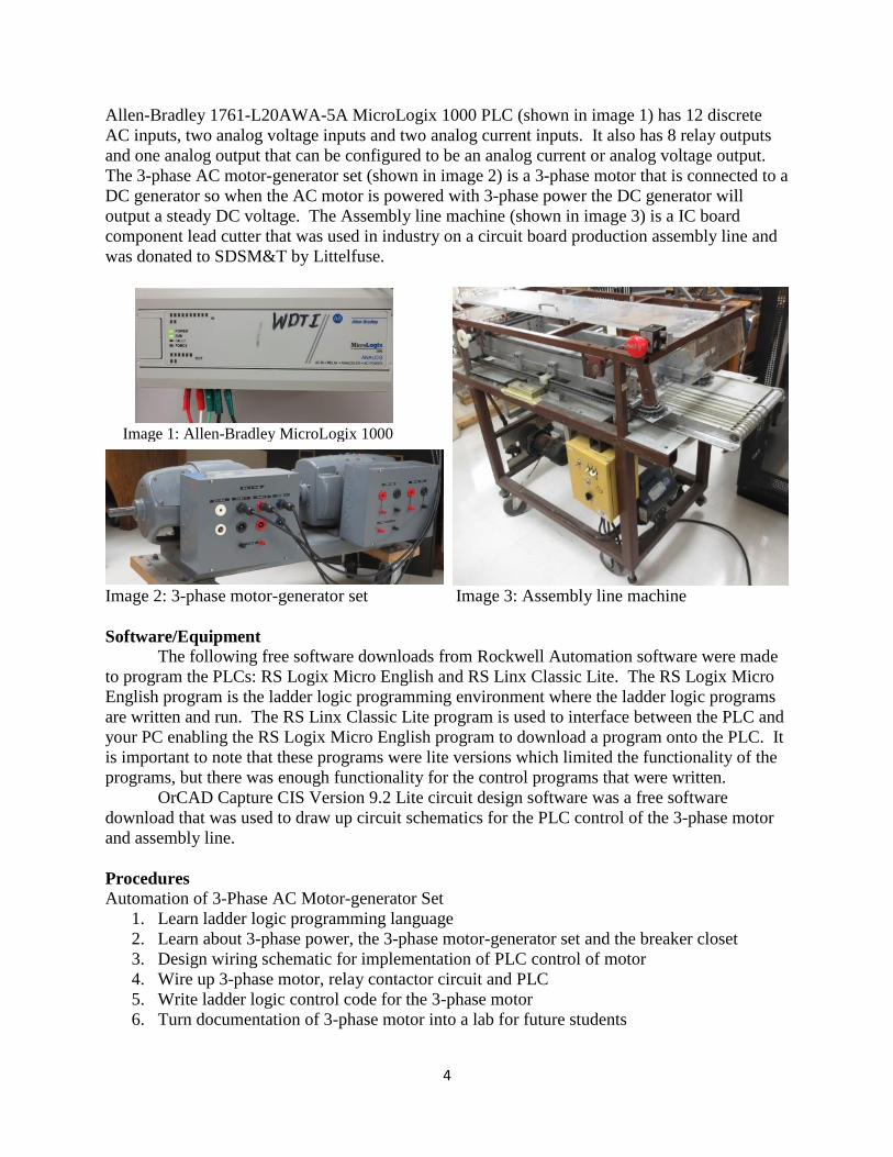
Allen-Bradley 1761-L20AWA-5A MicroLogix 1000 PLC (shown in image 1) has 12 discrete
AC inputs, two analog voltage inputs and two analog current inputs. It also has 8 relay outputs
and one analog output that can be configured to be an analog current or analog voltage output.
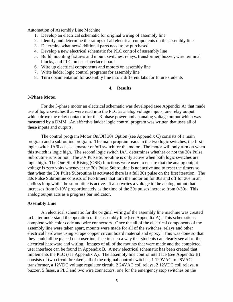
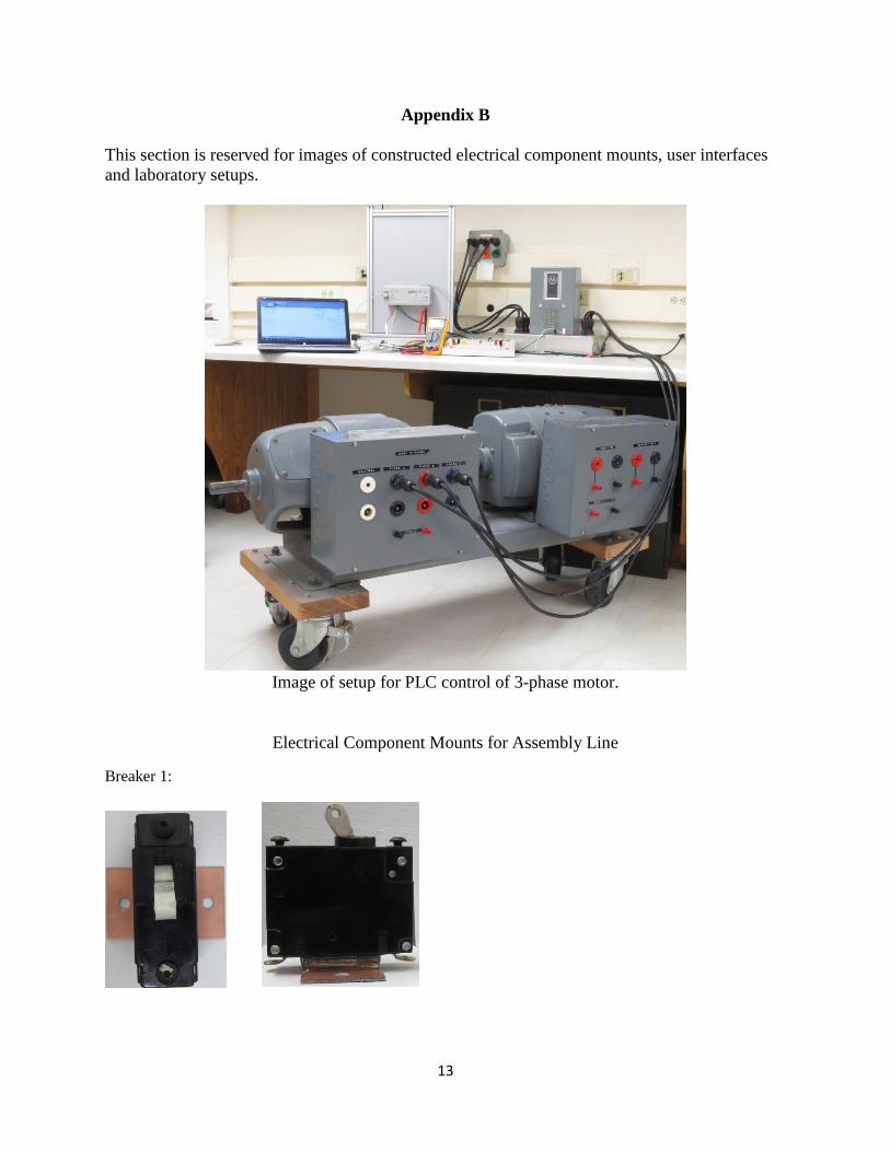
The 3-phase AC motor-generator set (shown in image 2) is a 3-phase motor that is connected to a
DC generator so when the AC motor is powered with 3-phase power the DC generator will
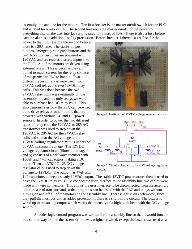
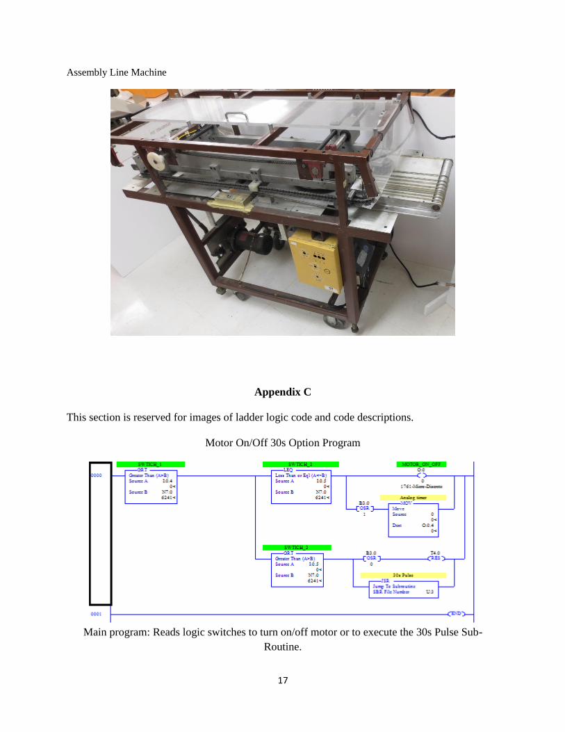
output a steady DC voltage. The Assembly line machine (shown in image 3) is a IC board
component lead cutter that was used in industry on a circuit board production assembly line and
was donated to SDSM&T by Littelfuse.
Image 2: 3-phase motor-generator set Image 3: Assembly line machine
Software/Equipment
The following free software downloads from Rockwell Automation software were made
to program the PLCs: RS Logix Micro English and RS Linx Classic Lite. The RS Logix Micro
English program is the ladder logic programming environment where the ladder logic programs
are written and run. The RS Linx Classic Lite program is used to interface between the PLC and
your PC enabling the RS Logix Micro English program to download a program onto the PLC. It
is important to note that these programs were lite versions which limited the functionality of the
programs, but there was enough functionality for the control programs that were written.
OrCAD Capture CIS Version 9.2 Lite circuit design software was a free software
download that was used to draw up circuit schematics for the PLC control of the 3-phase motor
and assembly line.
Procedures
Automation of 3-Phase AC Motor-generator Set
1. Learn ladder logic programming language
2. Learn about 3-phase power, the 3-phase motor-generator set and the breaker closet
3. Design wiring schematic for implementation of PLC control of motor
4. Wire up 3-phase motor, relay contactor circuit and PLC
5. Write ladder logic control code for the 3-phase motor
6. Turn documentation of 3-phase motor into a lab for future students
Image 1: Allen-Bradley MicroLogix 1000
PLC
5
Automation of Assembly Line Machine
1. Develop an electrical schematic for original wiring of assembly line
2. Identify and determine the ratings of all electrical components on the assembly line
3. Determine what new/additional parts need to be purchased
4. Develop a new electrical schematic for PLC control of assembly line
5. Build mounting fixtures and mount switches, relays, transformer, buzzer, wire terminal
blocks, and PLC on user interface board
6. Wire up electrical components and motors on assembly line
7. Write ladder logic control programs for assembly line
8. Turn documentation for assembly line into 2 different labs for future students
4. Results
3-Phase Motor
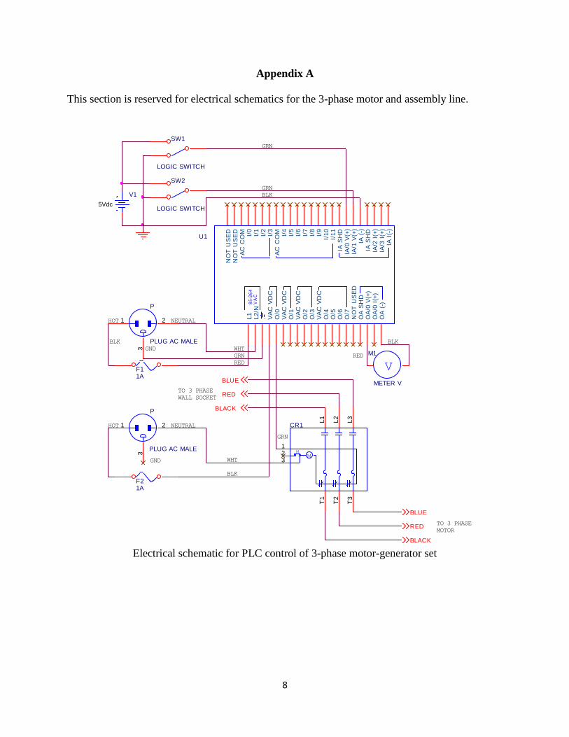
For the 3-phase motor an electrical schematic was developed (see Appendix A) that made
use of logic switches that were read into the PLC as analog voltage inputs, one relay output
which drove the relay contactor for the 3-phase power and an analog voltage output which was
measured by a DMM. An effective ladder logic control program was written that uses all of
these inputs and outputs.
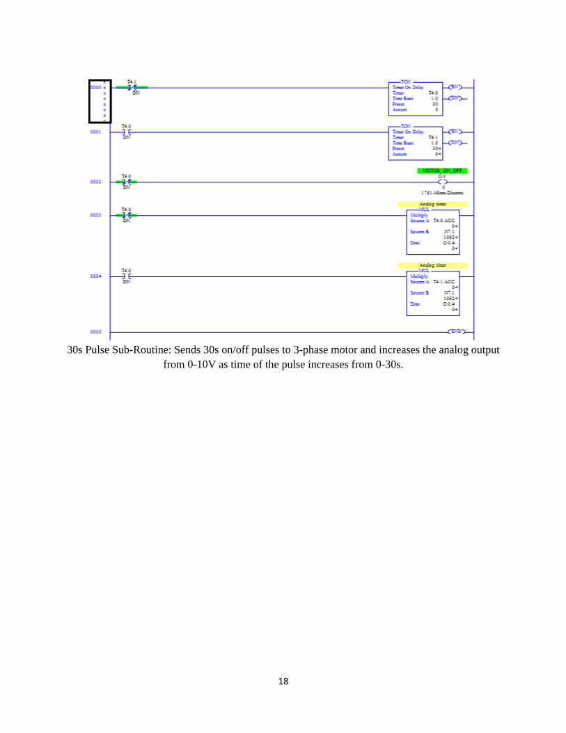
The control program Motor On/Off 30s Option (see Appendix C) consists of a main
program and a subroutine program. The main program reads in the two logic switches, the first
logic switch IA/0 acts as a master on/off switch for the motor. The motor will only turn on when
this switch is logic high. The second logic switch IA/1 determines whether or not the 30s Pulse
Subroutine runs or not. The 30s Pulse Subroutine is only active when both logic switches are
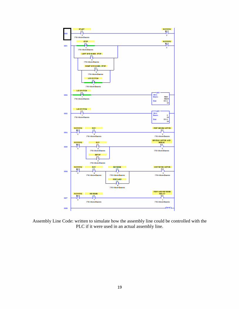
logic high. The One-Shot-Rising (OSR) functions were used to ensure that the analog output
voltage is zero volts whenever the 30s Pulse Subroutine is not active and to reset the timers so
that when the 30s Pulse Subroutine is activated there is a full 30s pulse on the first iteration. The
30s Pulse Subroutine consists of two timers that turn the motor on for 30s and off for 30s in an
endless loop while the subroutine is active. It also writes a voltage to the analog output that
increases from 0-10V proportionately as the time of the 30s pulses increase from 0-30s. This
analog output acts as a progress bar indicator.
Assembly Line
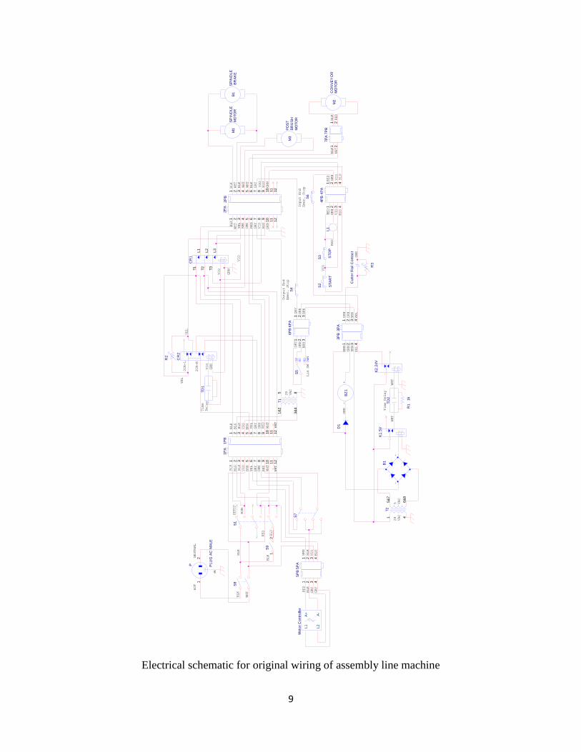
An electrical schematic for the original wiring of the assembly line machine was created
to better understand the operation of the assembly line (see Appendix A). This schematic is
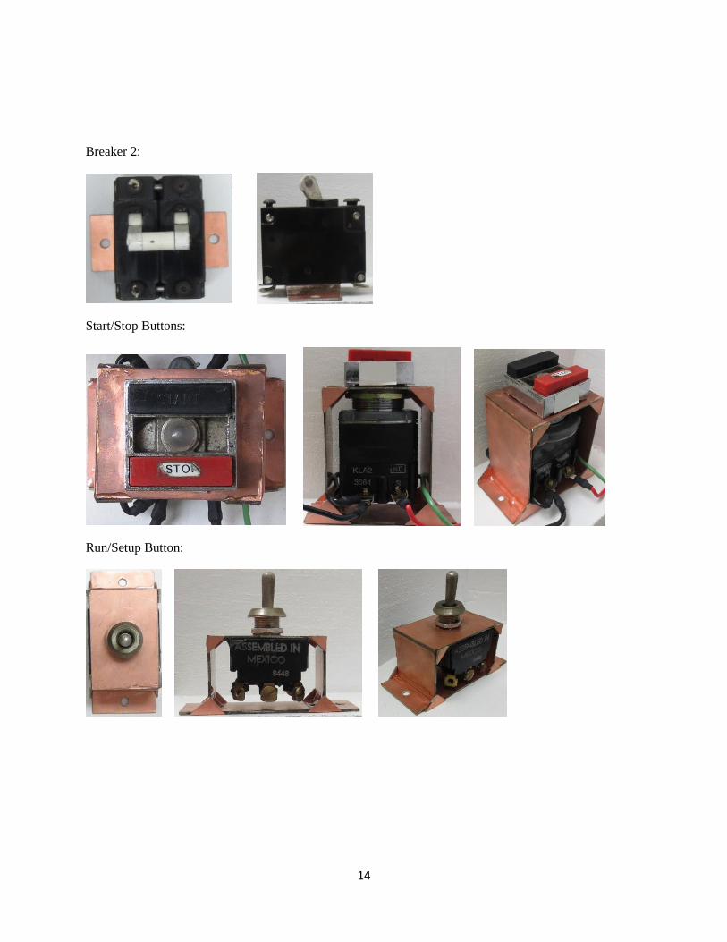
complete with color code and wire connectors. Once the all of the electrical components of the
assembly line were taken apart, mounts were made for all of the switches, relays and other
electrical hardware using scrape copper circuit board material and epoxy. This was done so that
they could all be placed on a user interface in such a way that students can clearly see all of the
electrical hardware and wiring. Images of all of the mounts that were made and the completed
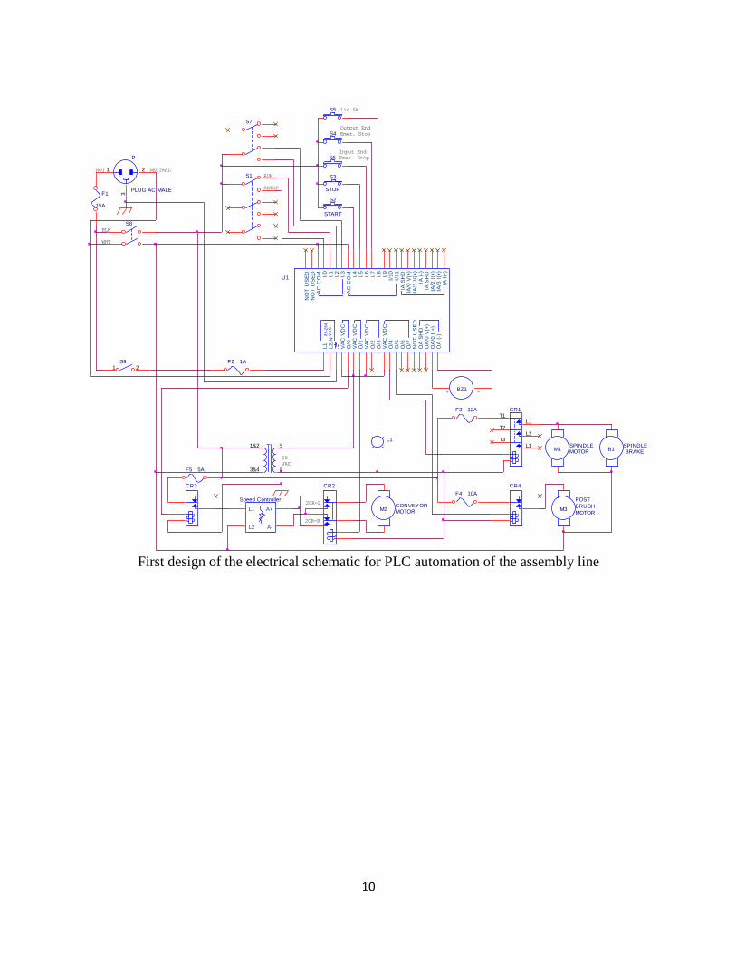
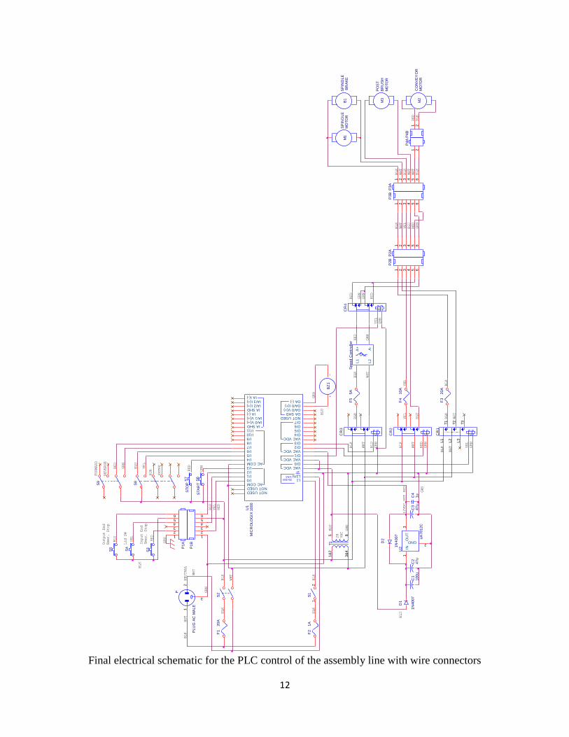
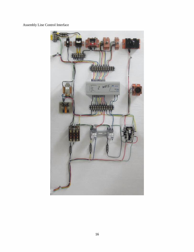
user interface can be found in Appendix B. A new electrical schematic has been created that
implements the PLC (see Appendix A). The assembly line control interface (see Appendix B)
consists of two circuit breakers, all of the original control switches, 1 120VAC to 28VAC
transformer, a 12VDC voltage regulator circuit, 2 24VAC coil relays, 2 12VDC coil relays, a
buzzer, 5 fuses, a PLC and two wire connectors, one for the emergency stop switches on the
6
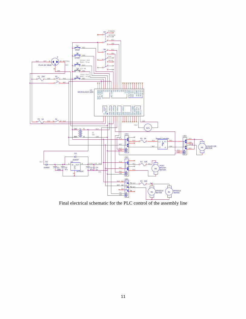
assembly line and one for the motors. The first breaker is the master on/off switch for the PLC
and is rated for a max of 5A. The second breaker is the master on/off for the power to
everything else on the user interface and is rated for a max of 30A. There is also a fuse before
each breaker as an additional safety precaution. Before breaker 1 there is a 1A fuse for the
power to the PLC. Before the second breaker
there is a 20A fuse. The start/stop push
buttons, emergency stop push buttons and the
two 3-position switches are powered with
120VAC and are read as discrete inputs into
the PLC. All of the motors are driven using
external relays. This is because they all
pulled to much current for the relay contacts
of this particular PLC to handle. Two
different types of relays were used, two
24VAC coil relays and two 12VDC relay
coils. This was done because the two
24VAC relay coils were originally on the
assembly line and the only relays we were
able to purchase had DC relay coils. This
also demonstrates how the PLC can be wired
up to drive relays or other motors that are
powered with various AC and DC power
sources. In order to power the two different
types of relay coils the 120VAC to 28VAC
transformer was used to step down the
120VAC to 28VAC for the 24VAC relay
coils and so that the AC voltage to the
12VDC voltage regulator circuit is under the
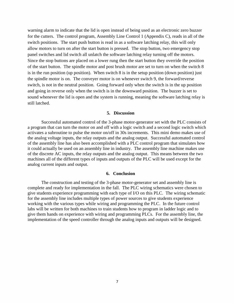
30VAC maximum voltage. The 12VDC
voltage regulator circuit (Shown in image 4
and 5) consists of a half wave rectifier with
100uF and 47uF capacitors making a DC
input. Then a uA7812C 12VDC voltage
regulator chip is used to step down the
voltage to 12VDC. The output has 47uF and
1uF capacitors to keep a steady 12VDC output. The stable 12VDC power source then is used to
drive the 12VDC relay coils. To connect the user interface to the assembly line two cables were
made with wire connectors. This allows the user interface to be disconnected from the assembly
line for ease of transport and so that programs can be tested with the PLC and relays without
turning on and off all of the motors on the assembly line. There is a fuse on each motor, since
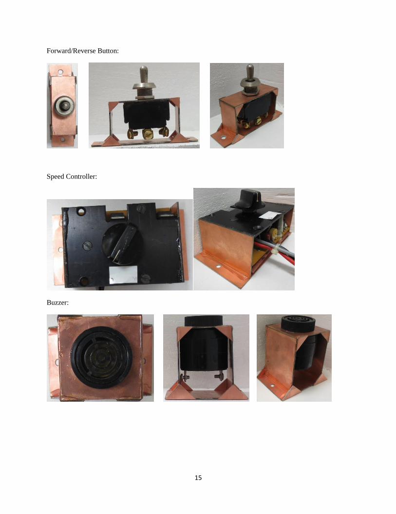
they pull the most current, as added protection if there is a short in the circuit. The buzzer is
wired up to the analog output which varies the intensity of a high pitch beep with the DC voltage
sent to it.
A ladder logic control program was written for the assembly line so that it would function
in a similar way to how the assembly line was originally wired, except the buzzer was used as a
GRNBLU
GRN
D1
1N4007
RED
U2
uA7812C
1 3
2
IN OUT
GN
D
C1100u
12VDC OUT
C247u
D2
1N4007
RED
C41u
BLU
C347u
Image 4: Perfboard of 12VDC voltage regulator circuit.
Image 5: Circuit schematic of 12VDC voltage regulator
circuit.
7
warning alarm to indicate that the lid is open instead of being used as an electronic zero buzzer
for the cutters. The control program, Assembly Line Control 1 (Appendix C), reads in all of the
switch positions. The start push button is read in as a software latching relay, this will only
allow motors to turn on after the start button is pressed. The stop button, two emergency stop
panel switches and lid switch all unlatch the software latching relay turning off the motors.
Since the stop buttons are placed on a lower rung then the start button they override the position
of the start button. The spindle motor and post brush motor are set to turn on when the switch 8
is in the run position (up position). When switch 8 is in the setup position (down position) just
the spindle motor is on. The conveyer motor is on whenever switch 9, the forward/reverse
switch, is not in the neutral position. Going forward only when the switch is in the up position
and going in reverse only when the switch is in the downward position. The buzzer is set to
sound whenever the lid is open and the system is running, meaning the software latching relay is
still latched.
5. Discussion
Successful automated control of the 3-phase motor-generator set with the PLC consists of
a program that can turn the motor on and off with a logic switch and a second logic switch which
activates a subroutine to pulse the motor on/off in 30s increments. This mini demo makes use of
the analog voltage inputs, the relay outputs and the analog output. Successful automated control
of the assembly line has also been accomplished with a PLC control program that simulates how
it could actually be used on an assembly line in industry. The assembly line machine makes use
of the discrete AC inputs, the relay outputs and the analog output. This means between the two
machines all of the different types of inputs and outputs of the PLC will be used except for the
analog current inputs and output.
6. Conclusion
The construction and testing of the 3-phase motor-generator set and assembly line is
complete and ready for implementation in the fall. The PLC wiring schematics were chosen to
give students experience programming with each type of I/O on this PLC. The wiring schematic
for the assembly line includes multiple types of power sources to give students experience
working with the various types while wiring and programming the PLC. In the future control
labs will be written for both machines to train students how to program in ladder logic and to
give them hands on experience with wiring and programming PLCs. For the assembly line, the
implementation of the speed controller through the analog inputs and outputs will be designed.
8
Appendix A
This section is reserved for electrical schematics for the 3-phase motor and assembly line.
Electrical schematic for PLC control of 3-phase motor-generator set
BLUE
GRN
RED
TO 3 PHASE
MOTOR
HOT NEUTRAL
BLACK
85
-26
4V
AC
U1
VA
C V
DC
O/0
NO
T U
SE
DN
OT
US
ED
AC
CO
M I/0
I/1
I/2
I/3
AC
CO
M I/4
I/5
I/6
I/7
I/8
I/9
I/1
0I/
11
L1
L2/N
. O/1
IA/1
V(+
)
IA S
HD
IA/0
V(+
)O
/7N
OT
US
ED
OA
SH
D
OA
(-)
IA (
-)IA
SH
D
O/2
O/3
VA
C V
DC
O/4
O/5
IA/2
I(+
)IA
/3 I
(+)
IA I
(-)
OA
/0 I
(+)
OA
/0 V
(+)
O/6
VA
C V
DC
VA
C V
DC
NEUTRAL
BLACK
MM
CR1
L2
T2
L3
T3
12
T1
L1
3
HOT
P
PLUG AC MALE
1 2
3
RED
RED
P
PLUG AC MALE
1 2
3
BLUE
V
M1
METER VTO 3 PHASE
WALL SOCKET
GRN
V1
5Vdc
F11A
GND
F21A
GRN
WHT
WHT
SW1
LOGIC SWITCH
BLK
GND
SW2
LOGIC SWITCH
BLK
BLK
GRN
RED
BLK
9
Electrical schematic for original wiring of assembly line machine
7P
A
1 2
VIO
GRN
BLK
BLK
D1
RUN
S4
RED
5 VAC
BLU
HOT
Time Delay
GRY
T2
15&
7
46&
8
BRN
R2
RED
S1
VIO
R1
1k
BRN
SP
IND
LE
MO
TO
RWHT
VIO
BRNGRY
T1
1&
25
3&
48
VIO
L1
SP
IND
LE
BR
AK
E
GRN
CR
2
BLK
WHT
YEL
RED
S2
STA
RT
RED
7P
B
1 2
RED
BLU
-+
B1
BRN
RED
BLK
RED
SETUP
2CR-R
Moto
r C
ontr
olle
r
L1
A+ A-
L2
GRN
4P
B
1 2 3 4
S6
GRY
BLK
M1
VIO
YEL
GRY
WHT
BLK
3P
A
1 2 3 4
ORN
BLU
M3
GRN
BLU
RED
ORN
K1 5
V
BLU
2P
B
1 2 3 4 5 6 7 8 9 10
11
12
BLU
+-
BZ
1
VIO
6P
A
1 2 3 YEL
BLK
VIO
BLK
BRN
CO
NV
EY
OR
MO
TO
R
5P
B
1 2 3 4
YEL
Cutt
er
Rail
Conta
ct
6P
B
1 2 3
YEL
GRN
BLK
YEL
B1
GRN
28
VAC
28
VAC
1P
B
1 2 3 4 5 6 7 8 9 10
11
12
S8
VIO
NEUTRAL
GRY
BLU
Input End
Emer. Stop
4P
A
1 2 3 4
ORN
NC
DWN
NO
UP
S5
BRN
CR
1
T2
L2
T3
L3
L1
T1
PO
ST
BR
US
H
MO
TO
R
BLK
BRN
VIO
S9
12
BLK
GRY
GRY
R3
M2
WHT
BRN
ORN
WHT
BLK
WHT
VIO
ORN
TD
1
BLK
GRN
WHT
1P
A
1 2 3 4 5 6 7 8 910
11
12
ORN
WHT
ORN
S7
BLK
3P
B
1 2 3 4
BLU
GRN
YEL
ORN
2P
A
1 2 3 4 5 6 7 8 910
11
12
BLK
Time
Delay
2CR-L
5P
A
1 2 3 4
K2 2
4V
WHT
WHT
Lid SW
GRN
GRY
WHT
S3 STO
P
WHT
TD
2
VIO
Output End
Emer. Stop
P PLU
G A
C M
ALE
12
3
RED
10
First design of the electrical schematic for PLC automation of the assembly line
F5 5A
S3
STOP
28
VAC
RUN
+ -BZ1
T11&2 5
3&4 8
S2
START
Input End
Emer. Stop
85
-26
4V
AC
U1
VA
C V
DC
O/0
NO
T U
SE
DN
OT
US
ED
AC
CO
M I/0
I/1
I/2
I/3
AC
CO
M I/4
I/5
I/6
I/7
I/8
I/9
I/10
I/11
L1
L2/N
. O/1
IA/1
V(+
)
IA S
HD
IA/0
V(+
)O
/7N
OT
US
ED
OA
SH
D
OA
(-)
IA (
-)IA
SH
D
O/2
O/3
VA
C V
DC
O/4
O/5
IA/2
I(+
)IA
/3 I
(+)
IA I
(-)
OA
/0 I
(+)
OA
/0 V
(+)
O/6
VA
C V
DC
VA
C V
DC
S7Output End
Emer. Stop
SETUP
F3 12A
L1
S4
S5 Lid SW
S91 2
POST
BRUSH
MOTOR
Speed Controller
L1 A+
A-L2
P
PLUG AC MALE
1 2
3
CR4
F4 10A
2CR-R
M1
2CR-L
M2
B1
HOT
S6
F2 1A
BLK
F1
15A
S8
CR3
NEUTRAL
M3
WHT
CR1
T2L2
T3L3
L1T1
SPINDLE BRAKE
CR2
SPINDLEMOTOR
S1
CONVEYORMOTOR
11
Final electrical schematic for the PLC control of the assembly line
BLK
YEL
CR1
L2T2
L3T3
T1L1
SETUP
M2
WHT
GRN
RED
S3
SPINDLE BRAKE
WHT
MICROLOGIX 1000
WHT
C347u
BLK
85
-26
4V
AC
U1
VA
C V
DC
O/0
NO
T U
SE
DN
OT
US
ED
AC
CO
M I/0
I/1
I/2
I/3
AC
CO
M I/4
I/5
I/6
I/7
I/8
I/9
I/1
0I/
11
L1
L2/N
. O/1
IA/1
V(+
)
IA S
HD
IA/0
V(+
)O
/7N
OT
US
ED
OA
SH
D
OA
(-)
IA (
-)IA
SH
D
O/2
O/3
VA
C V
DC
O/4
O/5
IA/2
I(+
)IA
/3 I
(+)
IA I
(-)
OA
/0 I
(+)
OA
/0 V
(+)
O/6
VA
C V
DC
VA
C V
DC
BLU
FORWARD
C1100u
BLU
C41u
BLK
RED
RED
S9
BLK
WHT
F3 20A
GRN
C247u
GRN
12VDC OUT
S5
GRN
RUN
S8
Output End
Emer. Stop
BLK
BLU
S6
START
SPINDLEMOTOR
RED
F4 10A
BLU
+ -BZ1
GRN
GRN
Speed Controller
L1 A+
A-L2
RED
GRN
S4
BLK
F2 1A
BLU
RED
NEUTRAL
BLK
F5 5A
BLK
CR2
BLK
T11&2 5
3&4 8
BLU
28
VAC
S2
GRN
F1 20A
BLK
YEL
BLU
U2
uA7812C
1 3
2
IN OUT
GN
DInput End
Emer. Stop
CR3
GRN
M3
YEL
GRN
B1
POST
BRUSH
MOTOR
D2
1N4007
Lid SW
WHT
WHT
CR4
BLK
YEL
P
PLUG AC MALE
1 2
3
BLK
REVERSE
S11 2
YEL
HOT
WHT
S7
STOP
CONVEYORMOTOR
YEL
RED
D1
1N4007
GRN
GRN
M1
GRN
RED
12
Final electrical schematic for the PLC control of the assembly line with wire connectors
GRN
BLK
P2A
1 2 3 4 5 6
U2
uA
7812C
13
2
INO
UT
GND
YEL
GRN
YEL
CR
4
BLU
GRN
85-264VAC
U1
VAC VDCO/0
NOT USEDNOT USED
AC COMI/0I/1I/2I/3
AC COMI/4I/5I/6I/7I/8I/9
I/10I/11
L1L2/N.
O/1
IA/1 V(+)
IA SHDIA/0 V(+) O/7
NOT USEDOA SHD
OA (-)
IA (-)IA SHD
O/2O/3VAC VDCO/4O/5
IA/2 I(+)IA/3 I(+)
IA I(-)
OA/0 I(+)OA/0 V(+)
O/6
VAC VDC
VAC VDC
WHT
BLK
BLU
RED
RED
BLU
F1
20A
WHT
M3
F3
20A
WHT
YEL
12VDC OUT
BLU
P1B
1234
65
WHT
F5
5A
WHT
RED
D2
1N
40
07
Input End
Emer. Stop
WHT
P4B
1 2
S6
STA
RT
BLK
GRN
GRN
S9
S8
Lid SW
BLK
+-
BZ
1
P2B
1 2 3 4 65RED
P3A
1 2 3 4 5 6
28
VAC
BLK
CR
3
BLK
NEUTRAL
C3
47u
SP
IND
LE
MO
TO
R
T1
1&
25
3&
48
GRN
SP
IND
LE
BR
AK
E
S5
S1
12
BLU
BLK
S2
RED
BLK
M2
PO
ST
BR
US
H
MO
TO
R
GRN
GRN
C4
1u
WHT
WHT
F2
1A
RED
RED
RED
P3B
1 2 3 4 65
YEL
YEL
BLK
YEL
FORWARD
F4
10A
S4
YEL
BLU
GRN
GRN
REVERSE
D1
1N
40
07
CR
2
BLU
BLK
CR
1
L2
T2
L3
T3
T1
L1
M1
BLU
RED
C2
47u
BLK
BLK
RUN
BLK
BLK
P
PL
UG
AC
MA
LE
12
3
WHT
GRN
Sp
ee
d C
on
tro
ller
L1
A+ A-
L2
GRN
RED
SETUP
P1A
123456
MIC
RO
LO
GIX
10
00
WHT
C1
100u
YEL
BLK
HOT
Output End
Emer. Stop
BLU
B1
BLK
RED
P4A
1 2
S7
STO
P
WHT
BLK
S3
CO
NV
EY
OR
MO
TO
R
GRN
GRN
BLK
GRN
13
Appendix B
This section is reserved for images of constructed electrical component mounts, user interfaces
and laboratory setups.
Image of setup for PLC control of 3-phase motor.
Electrical Component Mounts for Assembly Line
Breaker 1:
14
Breaker 2:
Start/Stop Buttons:
Run/Setup Button:
15
Forward/Reverse Button:
Speed Controller:
Buzzer:
16
Assembly Line Control Interface
17
Assembly Line Machine
Appendix C
This section is reserved for images of ladder logic code and code descriptions.
Motor On/Off 30s Option Program
Main program: Reads logic switches to turn on/off motor or to execute the 30s Pulse Sub-
Routine.
18
30s Pulse Sub-Routine: Sends 30s on/off pulses to 3-phase motor and increases the analog output
from 0-10V as time of the pulse increases from 0-30s.
19
Assembly Line Code: written to simulate how the assembly line could be controlled with the
PLC if it were used in an actual assembly line.
20
References
1. Allen-Bradley. (1998). User Manual: MicroLogix 1000 Programmable Controllers.
Retrieved from http://etidweb.tamu.edu/hsieh/ENTC410/Manual/MicroLogix1000-1761-
um003_-en-p.pdf
2. Petruzella, F. D. (2011). Programmable Logic Controllers (4th ed.). New York, NY:
McGraw-Hill.
3. Ron Beaufort Training. (2009, March 24). 1 - Problem: Mistakes & Misconceptions (AB PLC
Training) [Video file]. Retrieved from https://www.youtube.com/watch?v=T3tnXu-Eywc
4. Ron Beaufort Training. (2009, March 24). 2 - Basic Inputs and Outputs (AB PLC Training)
[Video file]. Retrieved from https://www.youtube.com/watch?v=jhLIOM1gfgk
5. Ron Beaufort Training. (2009, March 24). 3 - Introducing the PLC Processor (AB PLC Training)
[Video file]. Retrieved from https://www.youtube.com/watch?v=xywXrN6AJGs
6. Ron Beaufort Training. (2009, March 24). 4 - Fundamentals of the Scan Sequence (AB PLC
Training) [Video file]. Retrieved from https://www.youtube.com/watch?v=8qqv2M_3DeI
7. Ron Beaufort Training. (2009, March 24). 5 - Understanding Bits and Instructions (AB PLC
Training) [Video file]. Retrieved from https://www.youtube.com/watch?v=iO9UzFafUpE
8. Ron Beaufort Training. (2009, March 24). 6 - Basic Instruction XIC (AB PLC Training) [Video
file]. Retrieved from https://www.youtube.com/watch?v=HniwADNPX5A
9. Ron Beaufort Training. (2009, March 24). 7 - Basic Instruction OTE (AB PLC Training) [Video
file]. Retrieved from https://www.youtube.com/watch?v=q4JSrEVOgok
10. Ron Beaufort Training. (2009, March 24). 8 - Basic Instruction XIO (AB PLC Training) [Video
file]. Retrieved from https://www.youtube.com/watch?v=7Sf6qNRuluc
11. Ron Beaufort Training. (2009, March 24). 9 - Solution: Step-by-Step Analysis (AB PLC Training)
[Video file]. Retrieved from https://www.youtube.com/watch?v=B9HYUbyTKhU
12. Ron Beaufort Training. (2009, March 24). 10 - Which Rung Wins? (AB PLC Training) [Video
file]. Retrieved from https://www.youtube.com/watch?v=rnsQpgrByNI
13. Ron Beaufort Training. (2009, March 24). 11 - Retentive Instructions OTL and OTU (AB PLC
Training) [Video file]. Retrieved from https://www.youtube.com/watch?v=KraWAA_i9GM
14. Q Corporation. (2003). Operators Manual: IVB.
Acknowledgments
Thanks to the National Science Foundation for funding this project through the REU Site:
Bringing Us Together, Improving Communications and Lives grant # EEC-1359476. Special
thanks to Littelfuse for donating the assembly line machine that was used for this project. I
would also like to thank my advisor Scott Rausch for all of the guidance he provided during this
project and Dr. Alfred Boysen for his critics of my speaking and writing.