Embed Size (px)
Citation preview
Loughborough UniversityInstitutional Repository
Precision cast tooling
This item was submitted to Loughborough University's Institutional Repositoryby the/an author.
Additional Information:
• A Doctoral Thesis. Submitted in partial fulfilment of the requirementsfor the award of Doctor of Philosophy at Loughborough University.
Metadata Record: https://dspace.lboro.ac.uk/2134/28054
Publisher: c© A.J. Clegg
Rights: This work is made available according to the conditions of the CreativeCommons Attribution-NonCommercial-NoDerivatives 2.5 Generic (CC BY-NC-ND 2.5) licence. Full details of this licence are available at: http://creativecommons.org/licenses/by-nc-nd/2.5/
Please cite the published version.

This item was submitted to Loughborough University as a PhD thesis by the author and is made available in the Institutional Repository
(https://dspace.lboro.ac.uk/) under the following Creative Commons Licence conditions.
For the full text of this licence, please go to: http://creativecommons.org/licenses/by-nc-nd/2.5/

•
LOUGHBOROUGH UNIVERSITY OF TECHNOLOGY
LIBRARY
AUTHOR/FILING TITLE
__________ __ ~~_e_~~ /._A~ ____________________ '
t "·~~nH ' --"CC-ES-SI(WriPY~~. ,·~~ll~t·,t~"'·· 1Jiti.T-·----~:1 >":\Jt' aUfil ~J"IJII~*\f, ..... - ,
--VOL~NO~ ~~-----]~~tlg~~K------~-------- --
R'_I-_ 4h"''' IIIS·l.o<»c LcafBlluhng-An foklcn"Printing-SLalionel)'
(
"

PRECISION CAST TOOLING
by
A J CLEGG
BTech, MSc (Loughborough)
A Doctoral Thesis submitted in partial fulfilment of the
requirements for the award of Doctor of Philosophy of the
Loughborough University of Technology
C by A J Clegg (1984)

·

------------------------------------------ -
SYNOPSIS
The thesis reports an investigation concerned with the optimisation of
materials and methods in the production of precision cast Hl3 die steel
tooling. The investigation was conducted in four stages:
mould material evaluation
metallurgical processing
test casting production and evaluation
finishing procedures
The mould material evaluation considered the properties and performance
of materials used in the production of composite moulds. These moulds
were produced using a molochite backing material bonded with sodium
silicate and a facing material of mullite bonded with ethyl silicate.
An appropriate mould processing procedure was established based on the
results of the mould material evaluation.
In the stage concerned with metallurgical processing, the principal
objective was to establish the most suitable method of suppressing the
pitting defect associated with the production of cast Hl3 die steel.
The effects of: mould atmosphere; mould material additions; mould and
metal temperature; and melt additions on the severity of the pitting
defect were assessed. The results enabled recommended procedures to be
established.
The results from the first two stages were used to formulate the
programme for test casting production and evaluation. The objectives
of this stage of the investigation were the confirmation, or otherwise,
of the findings and recommendations of the previous stages and the
establishment of the attainable precision in test castings, which
included industrial components. The castings were assessed using
dimensional metrology and surface finish measurements.
In the final stage of the investigation the effect of heat treatment on
the dimensions of the test castings was established. An attempt was
also made to quantify the effects of electrical discharge machining
(EDM) on the surface composition of the as-cast material using electron
probe microanalysis.
ACKNOWLEDGEMENTS
The author wishes to recorQ his acknowledgements to the following:
Professor R J Sury, Head of the Department of Engineering Production
and Director of Research, for providing the opportunity, encouragement
and facilities necessary to carry out this work.
Dr A A Das, Research Supervisor, for his guidance and encouragement.
Mr R Pearson, Research Technician, for engineering skills, technical
support and enthusiasm, without which the project could not have been
completed.
Mr B J Goodman, Mr A Haigh and Mr R Parker, Technical Staff, for their
assistance with experimental work.
Dr P R Gibson, Technical Tutor, .for assistance during the final
experimental work and especially with metrology.
Dr D H Ross, Experimental Officer in the Department of Materials
Engineering and Design, for conducting the Electron Probe Microanalysis
work.
Finally, the author acknowledges the financial support provided by the
Science and Engineering Research Council (Research Grant Reference:
BRIG 99276).
ii
CHAPTER ONE
CHAPTER TWO
CHAPTER THREE
CHAPTER FOUR
CHAPTER FIVE
CHAPTER SIX
CHAPTER SEVEN
CHAPTER EIGHT
CONTENTS
Introduction and Statement of the Problem
2.1 The Shaw Process
2.2 Metallurgical Processing of Die Steels
Electrical Discharge Machining
Experimental Approach and Design of Equipment
4.1 Introduction
4 • .2 Evaluation of Mould Materials
4.3 Mould Manufacture
4.4 Metal Melting and Treatment
4.5 Requirements for Finishing
Results
5.1 Introduction
5.2 Mould Material Evaluation
5.3 Metallurgical Processing
5.4 Test Castings Evaluation
5.5 Finishing Procedures
Observations and Discussion
6.1 Introduction
6.2 Mould Material Evaluation
6.3 Metallurgical Processing
6.4 Test Castings Evaluation
6.5 Finishing Procedures
6.6 Discussion Summary
Conclusions
Suggestions for Further Work
iii
Page Number
14
23
30
39
40
44
53
58
61
62
65
67
104
115
116
124
132
1 51
159
162
165

REFERENCES 167
APPENDICES 1 Naterials used in the Ceramic 172 Slurry Process
2 The COz/Silicate Process .179
3 Nould Material Tests 185
4 Feeding and Gating Calculations 189
5 Nelting Stock Analyses 198
6 Naterials and Equipment Suppliers 199
7 Statistical Analyses 202
8 Related Publications 21 1
iv
CHAPTER ONE
INTRODUCTION AND STATEMENT OF THE PROBLEM
Impression moulds and dies are used for a variety of applications in
the field of manufacturing technology. They are tools which contain
the workpiece shape totally or"partlY as a negative shape. This
negative shape will either be impressed on the workpiece as a positive
shape, or it is used to hold a component for a secondary operation.
The dies usually consist of two, three and sometimes more parts for
more complex workpieces. Toolset components with internal contours
are usually termed 'die', while parts with external features may be
considered punches. The working surface of impression dies lies
between a few mm2 and a few m2, the mass ranging from less than 0.1 kg
to more than 50 tonnes (1).
Some of the principal applications of dies and moulds are:
Casting:
Forming and forging:
Plastics and rubbers:
Glass:
gravity die casting
pressure die casting
foundry pattern tooling
drop forging
extrusion and wire drawing
stamping
powder metallurgy
low pressure moulding
high pressure moulding
extrusion
blow moulding
tyre moulds
gl as s moulds
From this list it may be seen that dies and moulds play an important
role in the economy of an industrial society such as that of the DK.
An efficient toolmaking industry is of fundamental importance to the
metal and plastics processing industry and, in turn, final product
manufacture (2).
1

1.1 DIE MATERIALS
The range of materials used in tool and die manufacture is extensive
and dependent on many factors. Non-ferrous alloys may be used for
foundry tooling, gravity die casting dies and plastic tooling. However,
in the majority of applications ferrous alloys are preferred. Although
cast iron is used in foundry tooling and press tooling, die steels
predominate. Die steels are characterised by high hardness and
resistance to abrasion coupled with, in many instances, resistance to
softening at elevated temperature (3). Generally, these attributes
are attained with high carbon and alloy content. Each manufacturing
process places different requirements on die material selection. In
the case of forging, die steels are selected on the basis of the
following characteristics (4):
I Ability to harden uniformly.
2 Ability to resist the abrasive action of the metal while it is
being forged.
3 Ability to withstand high pressures and heavy shock loads.
4 Ability to resist cracking and checking caused by heat.
Furthermore, selection of the most suitable combination of steel and
hardness for die blocks and die inserts is influenced by:
(i) Shape and size of the forging.
(ii) Composition of the metal to be forged.
(iii) Temperature at which the metal is to be forged.
(iv) Number of forgings to be made.
(v) Type of forging equipment (hammer or press).
(vi) Cost of the die steel.
(vii) Sequence of machining the die impressions (before or after
hardening) •
(viii) Forging tolerances (including those specified for draft angles).
(ix) Established plant practice and previous experience with
similar applications.
(x) Availability of auxiliary equipment.
As the various properties desired to meet specific forging conditions
are frequently incompatible with each other, compromises are necessary
in the selection of tool material and hardness.
2
A detailed consideration of die steel selection may be obtained from
the Metals Handbook (3,4).
1.2 DIE MANUFACTURE
The majority of dies and moulds start life ona one-off basis (5).
The conventional approach. to manufacture involves the construction of
a model which is then used for copy milling the required cavity in a
forged die block. Even when, as in forging or glass making, several
moulds may be required this approach is still used. The nature of
conventional machining processes is such that considerable skilled
hand finishing work, termed benching, is usually required to complete
the die.
The UK die and mould report showed that in 1968 there were 250
independent and 1000 tied die and mould making concerns responsible
for the production of tooling (6). For the year, independent toolrooms
produced dies and moulds to the value of £13M, tied tool rooms £60M
worth and a further £2M worth was imported. At that time it was
predicted that there would be a growth of 8% and 15% pa respectively
for tools for diecasting and plastics. However, the ·skilled labour
force was growing at a rate of only 4% pa. By 1975 it was estimated
that approximately 6000 skilled mould and die makers were employed in
the UK industry (7).
During the past decades there has been an increasing trend towards the
reduction of the amount of machining that is required of engineering
components (8). This has increased the importance of the processes
capable of producing more accurate components. Two factors are
involved: firstly an increasing requirement for· tooling for these
accurate processes, and secondly an increasing requirement for these
tools to be more accurate.
Die and mould costs represent a substantial proportion of the component co,t. It has been reported that in the USA the cost of making or replacing
dies for drop, upset, or press forgings can be as low as·a few hundred
dollars, or as much as 100,000 dollars or more (9). Dep~nding on the
type of forging and the material used, the cost of repairing and
replacing dies can add anything between 6% and 20% to the cost of a
finished forging.
3
Eventually, dies must be withdrawn from service because of wear. The
factors influencing die wear have been .. the subject of numerous investi
gations and reports. Forging handbooks list the following factors as
influencing the life of dies used in closed die forging: die material
and hardness; flow stress and.temperature of workpiece; scale; workpiece
design; tolerances of t.he workpiece; and rapidity and intensity of the
blow. The same handbooks mention the following factors as the main
causes for die failures:. overloading; overheating; abrasive wear; heat
checking and cold dies (10). Diecasting dies are subject to two
principal modes of failure: heat checking and die erosion.
In the more demanding·field of. forging, die life is a particular cause
of concern. The life of dies used for the same product cari vary from
.. afew hundred. to 50,000 plus· (11). Although there.is considerable
effort to control these die life variations by controlling process
parameters, the problem is still serious.
All these factors place considerable pressure on tool and die makers,
who often face criticism that. they are unable to meet delivery
schedules. These pr~ssures can be . summarised as:
(a) need. to find faster methods of sinking dies.
Cb). need to find cheaper methods of sinking dies.
(c) need to put impressions into dies with greater accuracy.
Cd) need to use materials with improved strength and also wear
resistance.
TO'help meet these requirements toolmakers have adopted new technology:
Ne machine tools; computer aided manufacture; and electro-discharge
machining (EDM).
A survey by Coates (12) which considered forging die sinking by ten
different methods in eight different firms concluded: the lowest
quoted times were obtained for completion of impression sinking and
benchwork operations and were associated with the employment of spark
erosion for the moulder and finisher impressions. When repeated
orders for dies are involved, as in forging, this is reflected still
further. The advantages of EDM include: reduction of skilled labour
requirements for process operation since the machines, once set,
operate automatically; reduction of skilled labour requirements in
4
bench finishing, since a better standard of machine finish can
generally be obtained by EDM.
1.3 CAST DIES AND MOULDS
An alternative to using metal removal processes to produce an impres
sion in ,a die is that of casting the required impression in a die
material. The cas ting process provides the designer wi th increased
scope and freedom for his ideas. Casting is the cheapest and most
convenient method of producing intricate detail and complex shapes in
a wide variety of metals and alloys, without a weight limitation. A
range of casting processes is available, the choice of process
depending upon such 'factors as size, number required and dimensional
. accuracy.
Two groups of processes may:be considered:
(I) Sand casting: green sand;. dry sand; cold setting processes; full
mould.
(11) Precision casting: plaster casting; shell moulding; investment
casting; Shaw process.
The processes in group I may be used to cast a component to shape, but
machining is generally required to produce a die of the required
dimensions. With the exception of the green sand process,. the processes
are suitable for the production of large press tools.
The processes in group 11 may, with the exercise of careful quality
control at all stages of production, be capable of producing cast to
size components. Under ideal conditions machining may not be required,
however, in most cases some finish machining may be necessary. Plaster
casting is limited to non-ferrous alloys, principally aluminium-base
alloys. Shell moulding and investment casting, although suitable for
. a broader range of alloys, are restricted to the production of small
castings. The Shaw process is perhaps the most versatile, being
suitable for a broad range of alloys and casting weights •
. . Some indication.of the scope of cast tooling and the range of materials
can be seen by reference to Table One.
5
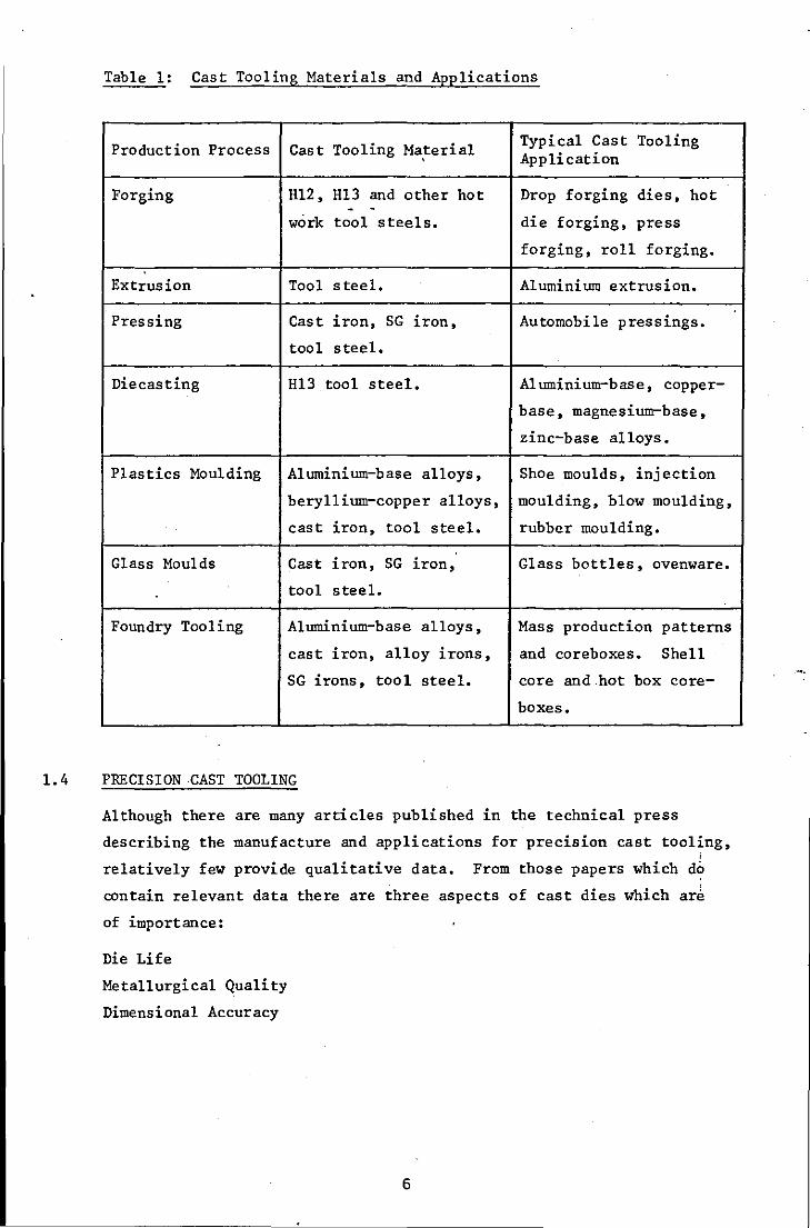
Table 1: Cast Tooling Materials and Applications
Production Process Cast Tooling Material Typical Cast Tooling , Application
Forging H12, Hl3 and other hot Drop forging dies, hot - -
work tool steels. die forging, press
forging, roll forging.
Extrusion Tool steel. Aluminium extrusion.
Pressing Cast iron, SG iron, Automobile pressings.
tool steel.
Diecasting Hl3 tool steel. Al uminium-base, copper-
base, magnesium-base,
zinc-base alloys.
Plastics Moulding Aluminium-base alloys, ShOe moulds, injection
beryllium-copper alloys, moulding, blow moulding,
cast iron, tool steel. rubber moulding.
Glass Moulds Cast iron, SG iron, Glass bottles, ovenware.
tool steel.
Foundry Tooling Aluminium-base alloys, Mass production patterns
cast iron, alloy irons, and core boxes. Shell
SG irons, tool steel. core and .hot box core-
boxes.
1.4 PRECISION CAST TOOLING
Although there are many articles published in the technical press
describing the manufacture and applications for precision cast tooling, ;
relatively few provide qualitative data. From those papers which do
contain relevant data there are three aspects of cast dies which ar~
of importance:
Die Life
Metallurgical Quality
Dimensional Accuracy
6
1.5 DIE LIFE
The initial industrial enthusiasm for precision cast dies arose from
the publication of a Czechoslovakian book on. the production of cast
cutting tools (13). In this book the authors also described the
production of cast forging dies by the Shaw process. They produced
several cast dies and compared their performance with dies machined
from wrought steel. The cast dies were reported to show an average
improvement in die life of 78.5%. The authors concluded that cast dies
gave better service performance at a lower production cost.
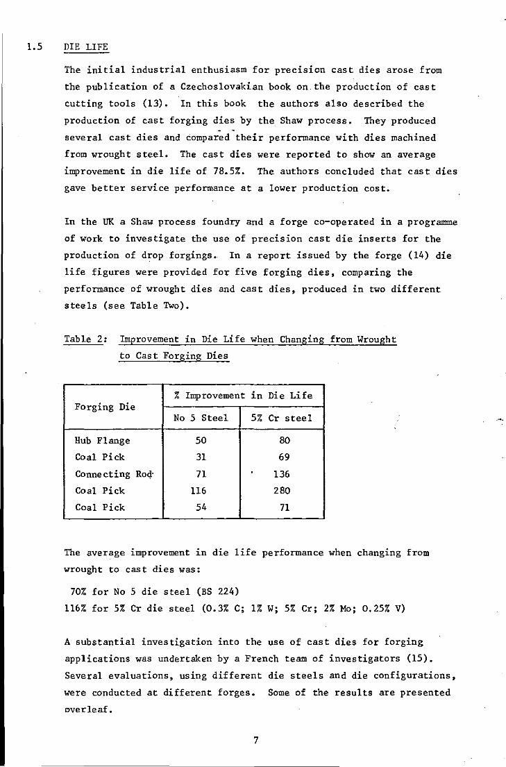
In the UK a Shaw process foundry and a forge co-operated in a programme
of work to investigate the use of precision cast die inserts for the
production of drop forgings.. In a report issued by the forge (14) die
life figures were provided for five forging dies, comparing the
performance of wrought dies and cast dies, produced in two different
steels (see Table Two).
Table 2: Improvement in Die Life when Changing from Wrought
to Cast Forging Dies
% Improvement in Die Life Forging Die
No 5 Steel 5% Cr steel
Hub Flange 50 80
Coal Pick 31 69
Connecting Roc!' 71 . 136
Coal Pick 116 280
Coal Pick 54 71
The average improvement in die life performance when changing from
wrought to cast dies was:
70% for No 5 die steel (BS 224)
116% for 5% Cr die steel (0.3% C; 1% W; 5% Cr; 2% Mo; 0.25% V)
A substantial investigation into the use of cast dies for forging
applications was undertaken by a French team of investigators (15).
Several evaluations, using different die steels and die configurations,
were conducted at different forges. Some of the results are presented
overleaf.
7
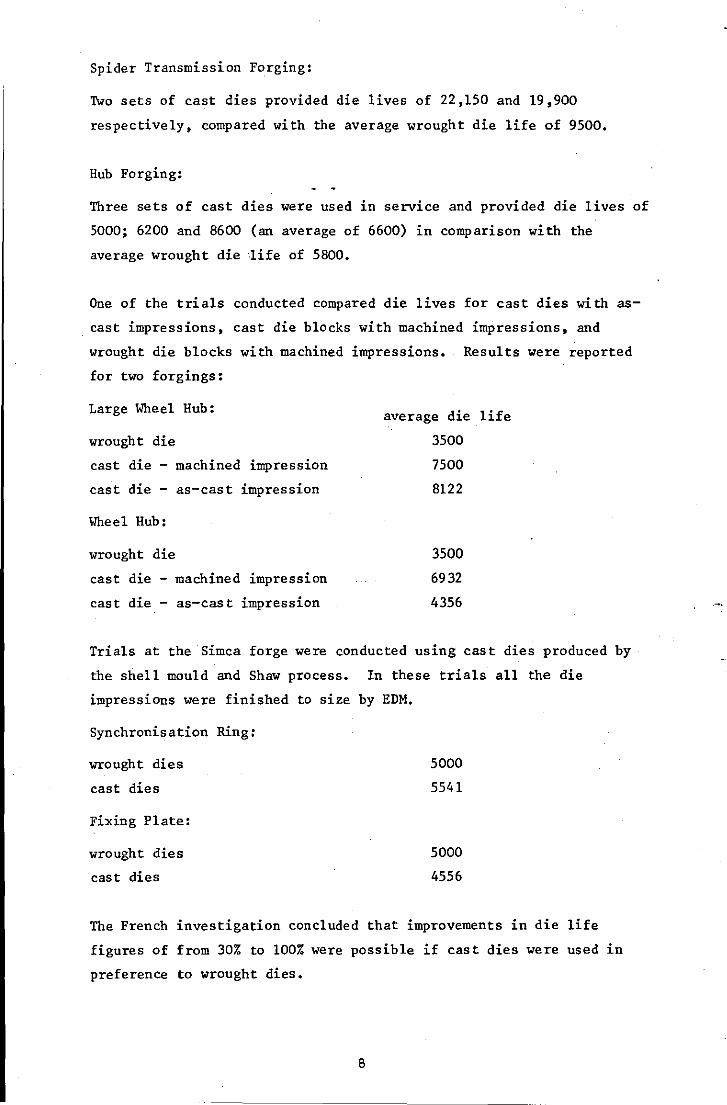
Spider Transmission Forging:
Two sets of cast dies provided die lives of 22,150 and 19,900
respectively, compared with the average wrought die life of 9500.
Hub Forging:
Three sets of cast dies were used in service and provided die lives of
5000; 6200 and 8600 (an average of 6600) in comparison with the
average wrought die 1ife of 5800.
One of the trials conducted compared die lives for cast dies with as
cast impressions, cast die blocks with machined impressions, and
wrought die blocks with machined impressions. Results were reported
for two forgings:
Large Wheel Hub:
wrought die
cast die machined impression
cast die - as-cast impression
Wheel Hub:
wrought die
cast die machined impression
cast die - as-cast impression
average die life
3500
7500
8122
3500
6932
4356
Trials at the Simca forge were conducted using cast dies produced by
the shell mould and Shaw process. In these trials all the die
impressions were finished to size by EDM.
Synchronisation Ring:
wrought dies
cast dies
Fixing Plate:
wrought dies
cast dies
5000
5541
5000
4556
The French investigation concluded that improvements in die life
figures of from 30% to 100% were possible if cast dies were used in
preference to wrought dies.
8
Many papers have been published on the use of precision cast dies in
the forging industry in the USA. Typical of these is one by Stutzman
(16) which provides twelve case studies on the successful introduction
of cast dies in place of wrought dies. Die life improvements gained
by using cast dies ranged from 20% to 150% when the cast and wrought
dies had been produced·from similar steels and had similar heat
treatment.
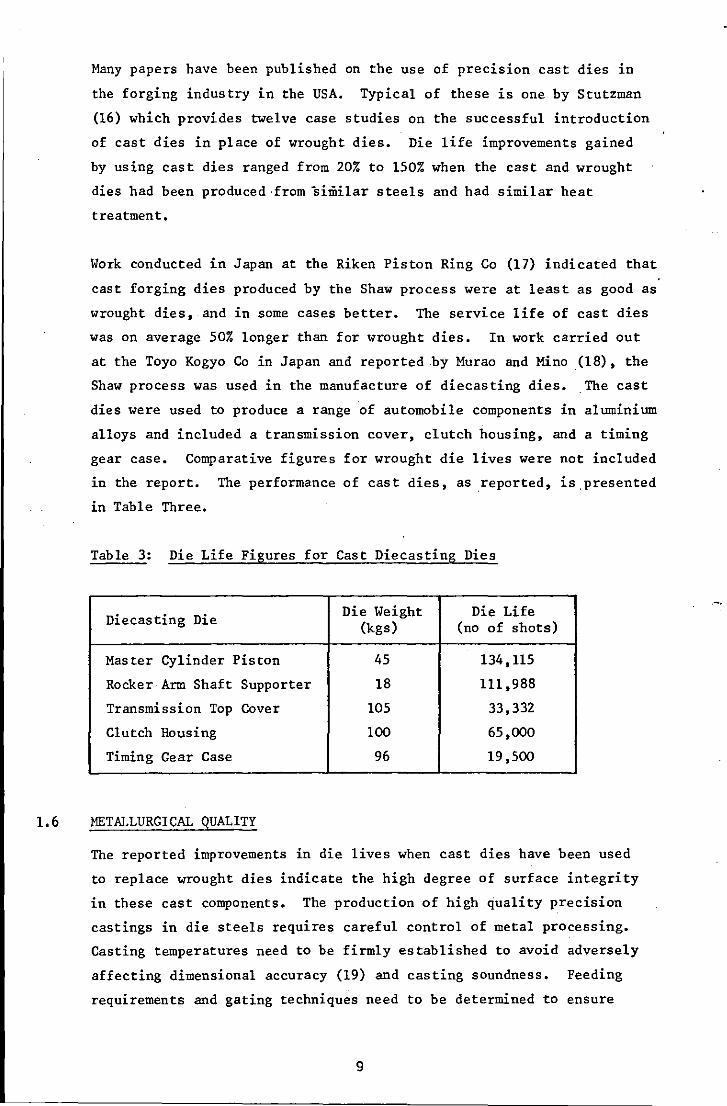
Work conducted in Japan at the Riken Piston Ring Co (17) indicated that
cast forging dies produced by the Shaw process were at least as good as
wrought dies, and in some cases better. The service life of cast dies
was on average 50% longer than for wrought dies. In work carried out
at the Toyo Kogyo Co in Japan and reported .by Murao and Mino .(18), the
Shaw process was used in the manufacture of diecasting dies. The cast
dies were used to produce a range of automobile components in aluminium
alloys and included a transmission cover, clutch housing, and a timing
gear case. Comparative figures for wrought die lives were not included
in the report. The performance of cast dies, as .reported, is.presented
in Table Three.
Table 3: Die Life Figures for Cast Diecasting Dies
Diecasting Die Die Weight Die Life (kgs) (no of shots)
Master Cylinder Piston 45 134,115
Rocker Arm Shaft Supporter 18 111,988
Transmission Top Cover 105 33,332
Clutch Housing 100 65,000
Timing Gear Case 96 19,500
1.6 METALLURGICAL QUALITY
The reported improvements in die lives when cast dies have been used
to replace wrought dies indicate the high degree of surface integrity
in these cast components. The production of high quality precision
castings in die steels requires careful control of metal processing.
Casting temperatures need to be firmly established to avoid adversely
affecting dimensional accuracy (19) and casting soundness. Feeding
requirements and gating techniques need to be determined to ensure
9
-------- -
that sound castings, free from inclusions, are produced. Grain
refining additions may be used to improve strength and reduce the
severity of subsequent heat checking of the ,die in service (20). Die
steels containing chromium must be processed correctly to ensure that
surface defects associated with high chromium contents are eliminated
and that surface decarburisation, which can result in early-die wear,
is controlled (21). The application of non-destructive testing
techniques enables the founder to guarantee the integrity of the
castings produced.
However, the production of a high integrity cast die, although
guaranteed free from defects, is not in itself a sufficient reason for
the improved die lives reported. Die life has been the subject of
investigation and a number of metallurgical reasons for the improved
performance of cast dies have been suggested. An investigation of
factors affecting heat checking revealed that, although heat checks
propagate in a similar manner in both cast and wrought dies, in cast
dies they extend into the casting to a shallow depth and then stop.
It is suggested that the lack of directionaL,ty in the grain structure
of castings is a significant factor (22). The non-directional grain
structure of the cast die material is also claimed to reduce' residual
stresses within the die and, as 'a result, castings do not warp or
distort during heat treatment to the extent that wrought dies do (20).
Metallurgical investigations comparing the properties of cast and
wrought H12 and Hl3 die steels have been reported in papers by Stutzman
(16,23,24). Extensive tests were undertaken on precision cast and
wrought material at room and elevated temperatures. The room
temperature results of ultimate tensile strength and yield strength
were similar for both materials, but the reduction in area and %
elongation test results were significantly lower for the cast material.
The difference in values of ductility was less pronounced in the tests
carried out at temperatures of 4800
C and 590o
C, and negligible at o 0
temperatures of 650 C and 705 C. At these latter temperatures the
ultimate tensile strength and yield strength values for the cast
material were slightly higher than those for the wrought material. Of
note was the existence of a true yield point in the cast samples, which
showed that the heat treated precision cast tool steel was not brittle.
10
The impact strength, measured by the Charpy V notch test, of the cast
material was appreciably lower than the wrought material when tested
at both room and elevated temperatures, but there was nO evidence of a
brittle fracture. Fatigue tests indicated that wrought steels were
inferior to the cast material when notched specimens were used.
However, with unnotched spec1mens the wrought specimens were much
superior.
Hot hardness tests conducted on material which had been heat treated
to give a hardness value of Rockwell C40 and C52 indicated that the
cast structure was superior to the wrought structure:
At 3l50
C to 4250
C the cast material was 1 RC harder
the cast material was 2-4 RC harder o
to 650 C the· cast material was 8 RC harder
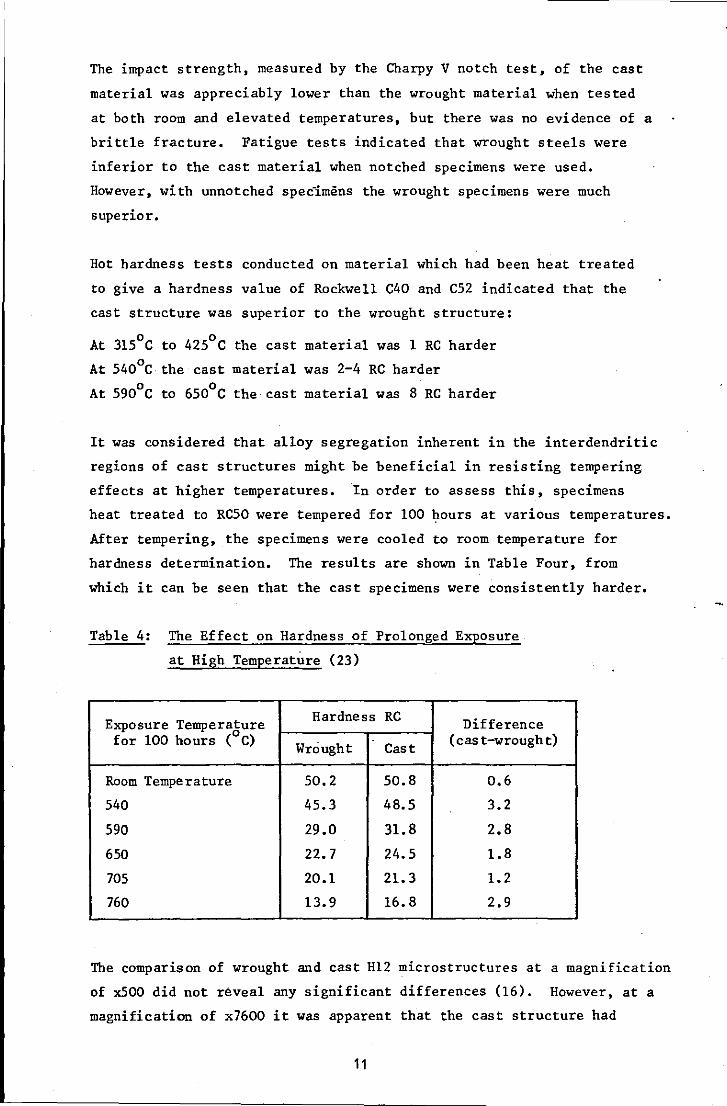
It was considered that alloy segregation inherent in the interdendritic
regions of cast structures might be beneficial in resisting tempering
effects at higher temperatures. In order to assess this, specimens
heat treated to RC50 were tempered for 100 hours at various temperatures.
After tempering, the specimens were cooled to room temperature for
hardness determination. The results are shown in Table Four, from
which it can be seen that the cast specimens were consistently harder.
Table 4: The Effect on Hardness of Prolonged Exposure
at High Temperature (23)
Exposure Temperature Hardness RC Difference 0 (cas t-wrough t) for 100 hours ( C) Wrought Cast
Room Temperature 50.2 50.8 0.6
540 45.3 48.5 3.2
590 29.0 31. 8 2.8
650 22.7 24.5 1.8
705 20.1 21.3 1.2
760 13.9 16.8 2.9
The comparison of wrought and cast H12 microstructures at a magnification
of XSOO did not reveal any significant differences (16). However, at a
magnification of x7600 it was apparent that the cast structure had
11
carbides more evenly dispersed throughout the material, whereas in the
wrought material the carbides were larger and.situated at grain
boundaries. It was considered that the structure of.the cast material
reduces wear at service temperatures and therefore contributed to the
improved die life of cast dies.
1.7 DIMENSIONAL ACCURACY
Detailed information about the dimensional accuracy of precision cast
dies is not readily available and one must. aSsume when reading the
literature that, because cast dies were used in production, their
. dimensional accura~y must have been satisfactory. The Czechoslovakian
work (13) indicated that as-cast dimensions were produced to within
0.3 mm (0.012 ins) without detailing actual dimensions. Jones (14)
gave very little specific detail, although some details were specified
for a hub flange forging cast die insert. This insert had external
dimensions of 133 mm (5.25 ins) diameter and was 76 mm (3 ins) thick.
The cavity dimensions of 46 mm (1.8125 ins), 57 mm (2.25 ins) deep with
a 76 mm (3 ins) square base were produced with a maximum dimensional
discrepancy of 0.08 mm (0.003 ins) which, as it was undersize, was
easily corrected.
The report of the work at Toyo Kogyo (18) concluded that precision
casting of diecasting dies to close tolerances is a technically
demanding process, in particular with regard to an accurate prediction
of contraction allowance •. This is especially so in the case of larger
dies, although small dies can be cast very precisely. Dimensions were
quoted for a four impression die having external dimensions of .360 mm
x 270 mm x 70 mm (14 ins x 10.5 ins x 2.75 ins) in Which the cavity
dimensions were within 0.05 mm to 0.18 mm (0.002 ins to 0.007 ins).
The Riken report (17) suggested that a finishing allowance of 0.05 mm!
25 mm (0.002 ins!l in) should be sufficient for the impressions in
forging dies, providing that the contraction allowance was accurately
predicted.
The French team (15) did not provide many details about dimensional
accuracy. They concluded that it was preferable, from an economic
viewpoint, to produce a casting of the impression with an acceptable
precision. The impression could then be finished by means of an
orthodox process, removing 0.1 mm to 1.0 mm (0.004 ins to 0.040 ins)
12
at different points of the impression, rather than try to produce a
precision casting to exact dimensions. American workers appear
similarly reluctant to quote actual dimensions and prefer to quote
general process tolerances. Typical values for Shaw process castings
are given below (25) :
For dimensions up to 25 nnn (1 in) ± 0.08 nnn (± 0.003 ins)
" " between 25 - 75 nnn (1 3 ins) ± 0.13 nnn (± 0.005 ins)
" " If 75 - 200 nnn (3 8 ins) ± 0.38 nnn (± 0.015 ins)
" " " 200 - 375 mm (8 15 ins) ± 0.76 nnn (± 0.030 ins),
" " over 375 nnn (15 ins) ± 1.14 nnn (± 0.045 ins)
For dimensions across the parting line of the mould an additional
tolerance of between ± 0.25 nnn and 0.50 nnn (0.010 ins and 0.020 ins)
must be provided. Surface finish values of 2 micrometres (SO micro
inches) cIa can be obtained, compared with values of 5 to 10 micrometres
(200 to 400 micro-inches) for sand moulded castings.
In the UK die users have been reluctant ,to use cast dies because of
defects traditionally associated with castings, such as porosity, blow
holes, surface 'imperfections and variations in metallurgical structure.
The obtainable precision and reproducibility of tolerances have also
b~en questioned in many instances. The criticisms applied, to some
extent, to precision cast dies produced using the Shaw process during
the late 1950's and early 1960's. It is possible that, at this time,
the UK foundry industry was not in a position to develop the production
of precision cast tooling. Certainly, the initial enthusiasm in the UK
did not result in the development of cast tooling to the extent that it
was developed in other European countries, Japan and the USA.
With this in mind the Science and Engineering Research Council has
provided funding for research into the optimisation of materials and
methods in the preparation of cast dies. This project is one of
several initiated by the SERC in the field of die and mould technology.
Other areas selected for investigation include: EDM; ECM; surface
coatings; heat treatment; heat transfer; CAD; manufacturing. economics;
costing and estimating.
13
CHAPTER TWO
2.1 THE SHAW PROCESS
2.1.1 Introduction
The Shaw Process is a precision casting process capable of the produc
tion of accurate castings with excellent surface finish and
metallurgical integrity. Moulds are produced using highly refractory
aggregates bonded with silica provided by a liquid ethyl silicate
binder. A high temperature firing treatment is a feature of the
production sequence and this produces an inert mould into which the
majority of commercial ferrous and non-ferrous alloys can be cast with
confidence.
The process has been used commercially for many years, it was known
before the Second World War that silicon esters could be used as
refractory aggregate binders (26). As with most processes there has
been a continuous development, in particular with respect to the binder
system and the methods of mould production. Many of these developments
are the subject of patents and much of the technical information has
been restricted to Shaw Process licensees.
2.1.2 Outline of the Process
The mould material is prepared by blending refractory powders,
containing a high proportion of fine material, with a liquid ethyl
silicate binder and a gelling agent. Careful selection of the
refractory material results in two particular advantages:
(i) The fine grains of refractory material provide a smooth surface
finish on the resultant casting.
(ii) The selection of a thermally stable refractory material ensures
that the mould is not subject to unpredictable dimensional changes
in contact with the molten metal during pouring, thus enabling an
accurate estimate of casting contraction to be made.
The blended, mobile liquid slurry is poured into the moulding box and
around the pattern. Within a short period of time, controlled by the
amount of gelling agent, the mould material gels to a rubbery
14
consistency and the pattern can be separated from the mould. The
nature of the process permits certain benefits to be gained at this
stage:
(a) Pouring a liquid slurry around the pattern ensures a high degree
of contact and therefor~ a~curacy and intricacy in the final
casting.
(b) The mould material sets in contact with the pattern and consequently
produces a mould which accurately reproduces the pattern detail.
(c) The rubbery nature of the mould allows the pattern to be withdrawn
without distortion to the mould, thus maintaining the dimensional
accuracy of the mould cavity.
On removal of the pattern the moulds are either torched immediately to
remove evolved alcohol (Shaw Process) or immersed in a stabilising bath
prior to torching (Unicast Process) (27). Torching produces a very
fine crazed surface and interior structure which does not affect the
casting surface, ie there is no metal penetration into the fine cracks,
but may improve permeability to allow the escape of air/gases during
casting. After torching the moulds are fired in a furnace at a
temperature up to lOOOoC, which ensures that there are no combustible
materials in the mould and that a strong, rigid, inert, accurate and
stable mould is produced. The stages in the production of a casting by
the Shaw Process are outlined in the flow diagram presented o.n ?CL~'f 222.
The advantages claimed for moulds manufactured by the Shaw Process
include the following (28):
1 Good pattern stripping characteristics: the rubbery nature of the
gelled mould provides flexibility to the mould which enables the
pattern and mould to be separated without damage to the mould when
intricate detail or even straight draws are required.
2 Dimensional stability: the excellent reproduction of pattern detail
and dimensions is retained by the mould to a great extent after
firing and during casting, thus enabling accurate dimensional
allowances to be made.
3 Mould strength: is sufficient to'allow moulds to be cast without
the need for moulding boxes.
4 Collapsibility and resistance to tears: the characteristic internal
structure of the mould material improves its breakdown properties
and there is less constraint of the casting during contraction.
15
5 Resistance to thermal shock: the characteristic internal structure
permits expansion of the mould material to occur readily, as a
result moulds can safely be poured cold.
6 Resistance to spalling and washing: the nature of the silica bond
prevents the generation of inclusions during mould filling.
7 Permeability and inertness: "as the mould is inert after firing the
only gas to be displaced is that occupying the mould cavity. The
characteristic structure provides sufficient permeability to enable
the metal to readily displace the gas through the mould.
2.1.3 The Binder
Ethyl silicate is an organic based silica binder that is free of those
alkaline salts which reduce the refractoriness of mould materials. It
is produced by reacting silicon tetrachloride (SiClq) with ethyl
alcohol (29):
SiC14 + 4C2HSOH + Si(OC2HS)q + 4HCl
and it is important to remove the hydrochloric acid so that subsequent
gelling characteristics may be easily controlled. If industrial
ethanol, which invariably contains some water, is used as an alternative
to pure ethyl alcohol, the product obtained is a mixture of tetra
ethoxysilane and ethoxypolysiloxanes. Tetraethoxysilane contains
approximately 28% silica by weight, whereas the ethoxypolysiloxanes,
which contain an average of up to five silicon atoms/molecule, contain
40% silica (30). This product is known as technical ethyl silicate
and, because of its higher silica content, is generally. preferred for
use in the foundry industry (31).
2.1.4 Hydrolysis
Ethyl silicate is a stable substance with no binding ability. It is
necessary to hydrolise the solution and cauSe it to react with water
in order to produce a solution which will deposit the adhesive form of
silica desirable for bonding refractory aggregates (32). Ethyl silicate
and water are immiscible unless a mutual solvent such as ethanol is
used (33), and it also serves to dilute the solution to the desired
silica content. The hydrolysis may be carried out under'either acid
or alkaline conditions (29). However, alkaline conditions usually
result in fairly rapid gelation and, consequently, acid hydrolysis is
preferred for foundry requirements. The preferred acid is hydrochloric
16
acid, although sulphuric or phosphoric acid are suitable. (33). The
acid hydrolysates prepared in this manner have a very good storage life
and are marketed as prehydrolysed ethyl silicates, which are ready for
direct use in the foundry.
2.1. 5 Gelation
In order to bind the refractory aggregate the ethyl silicate hydrolysate
must be made to gel. It is the gel which provides the bonding action
by two me thods (33):
(i) Air drying bond = 3H4Si04 + H2SiOS + H2Si03 + 4H20
(ii) Precipitation bond = 3H4Si04(gel) + 6H20
Upon heating, the silicic acid or silica gel binders condense to form
a refractory silica cement. It is this silica form which provides the
high strength dev'i'loped by firing.
There are many ways of promoting the gelling of an acid hydrolysed
ethyl silicate using the principle of pH control (32). Hydrolysed
ethyl silicate solutions are usually prepared with a pH value of between
1.5 and 3.0, at which they are relatively stable, they are also stable
at pH values above 7.0. They are inherently unstable at pH values
between 5.0 and 7.0. By adding an alkaline agent to the hydrolysed
ethyl silicate solution the pH value of the solution can be increased
to a value of 5.0, when the binder becomes unstable and gels. Ammonia,
ammonia salts - acetate, carbonate, hydroxide, or organic ammonia salts
- piperidine, morpholemar, triethylamine, may be used for this purpose.
The actual time for gelation will depend on the particular application
and can be varied by adjusting the amount of gelling agent addition.
If accurate control of setting time or a very long setting time is
required, use may be made of organotin catalysts (30). The organotin
catalysts enable hydrolysis and gelation to proceed readily in the
absence of either acid or base. By a special heat treatment process
the gelation characteristics can be altered to change the gel time when
water is added.
17
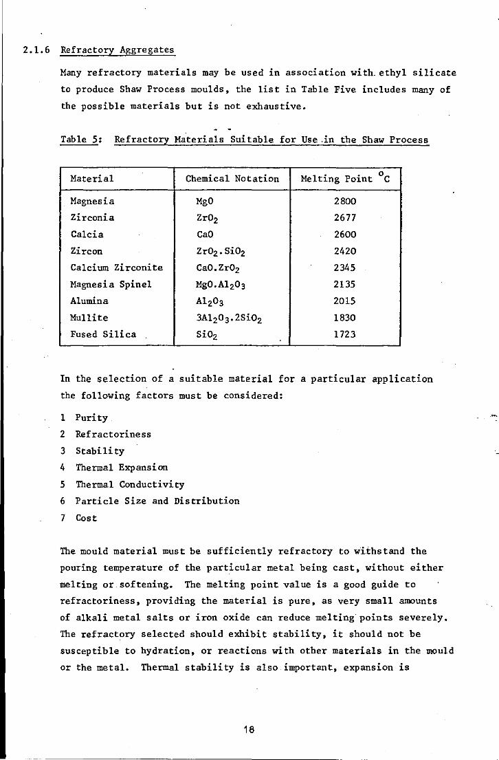
2.1.6 Refractory Aggregates
Many refractory materials may be used in association with_ethyl silicate
to produce Shaw Process moulds, the list in Table Five includes many of
the possible materials but is not exhaustive.
Table 5: Refractory Materials Suitable for Use _in the Shaw Process
Material Chemical Notation Melting Point °c
Magnesia MgO 2800
Zirconia Zr02 2677
Calcia CaO 2600
Zircon Zr02. Si02 2420
Calcium Zirconite CaO. Zr02 2345
Magnesia Spinel MgO. A1 203 2135
Alumina A1203 2015
Mullite 3A1203·2Si02 1830
Fused Silica Si02 1723
In the selection of a suitable material for a particular application
the following factors must be considered:
1 Purity
2 Refractoriness
3 Stability
4 Thermal Expansion
5 Thermal Conductivity
6 Particle Size and Distribution
7 Cost
The mould material must be sufficiently refractory to wii:hstand the
pouring temperature of the particular metal being cast, without either
melting or.softening. The melting point value is a good guide to
refractoriness, providing the material is pure, as very small amounts
of alkali metal salts or iron oxide can reduce melting points severely.
The refractory selected should exhibit stability, it should not be
susceptible to hydration, or reactions with other materials in the mould
or the metal. Thermal stability is also important, expansion is
18
inevitable, however, providing that it is predictable, ie constant and
reproducible it can be taken into account when estimating contraction
allowance.
Thermal conductivity is in part a property of the material selected,
but it is also a function of-particle size and distribution when that
material is used to produce a porous, particu1ate mould. The property
does influence the rate of solidification and heat transfer through a
mould, which may have an influence on metallurgical integrity.
Cost is a major factor in refractory material selection and is affected
by such factors as availability, purity and particle size requirement.
2.1.7 Moulding Mix Specification
The secret of successful mould production and quality castings lies in
the mould material mix' specification. It is essential to balance the
grades of refractory material with the volume of binder and amount of
gelling ag~nt in order to produce moulds of consistently high quality.
Shaw Process slurry preparation is critical (34), if it is too thin mould
cracking will occur on firing, and if it is too thick detail is lost 'and
air bubbles are trapped at the pattern surface.
When selecting the grades of refractory material to be used the
principles which apply to sand moulding can be used as a guide. Surface
finish will be improved when finer material is used, however,
permeability will decrease and binder requirement increase as a
consequence. The strength, measured conventionally by AFS compression
and tensile strength, will also be affected by grade selection.
Strength will be at a maximum when refractory grades are selected on the
basis of using several size gradings, which permit infi11ing of the
voids between larger grains by the smaller (32), this is also the most
economic way of using the binder. Mix specification is inevitably a
compromise between theoretical considerations and practical requirements,
but a reading of standard ceramic texts (35,36) can be invaluable.
2.1.8 Mould Production and Processing
As a principal advantage of the process is its ability to produce
castings to consistent and close dimensional tolerances, it is essential
that patterns and mould locating equipment be produced to a high
standard of accuracy.
19
2.1.9 Pattern Equipment
As a casting cannot contain more detail or be more accurate than the
pattern from which it was made, it follows that particular attention
must be paid to pattern construction and quality. The Shaw Process
utilises permanent pattern e9u~pment and, in principle, a wide range of
materials may be used (37): wood, plaster, graphite, epoxy resin, metal,
for examples. However" in practice the requirement for high standards
of accuracy reduces the choice. Wood patterns are affected by heat and
moisture and their dimensions can vary by'as much as 3%, which would
severely affect accuracy (37). Plastic resin patterns may also be
subject to distortion when used in conjunction with the ShawProcess
(34). To achieve good dimensional accuracy polished metal patterns are
preferred,. for which aluminium alloys are particularly. suitable.
Patterns are normally coated with a release agent, for example a 10%
solution of paraffin wax in benzene (38), or similar proprietary
products, and if sparingly applied and well buffed, pattern release from
the mould presents no problem.
2.1.10 Mould Production
Shaw Process moulds may be produced by one of several alternative
methods: for small components a ceramic shell is quite acceptable, for
larger components a boxless block mould is suitable. If the mould is
very large, of if demand for a particular casting is great and it is
desirable that mould material costs be reduced, a composite.mould can
be produced. In this case the facing material is Shaw based, but the
backing material might be sodium silicate bonded. For mass production
.applications the process, in each of these forms, lends itself to
mechanisation and rapid output of moulds.
In the production of composite moulds additional pattern requirements
in the form of a pre-form pattern may be necessary. These may be
produced in wood as their purpose is only to produce an.oversize cavity
in the backing mould. This mould is then positioned over the precision
pattern and the gap filled by introducing the mobile Shaw slurry. I
Permanent pre-form patterns are.not essential, the required effect can
be obtained by covering the precision pattern with a thickness of
material such as oil sand, C02 sand, felt, etc (38-41), which will
permit the oversize backing mould to be produced. To ensure that ,
20
separation of the backing and facing layers does not become a problem,
the mould materials selected for the backing and facing layers should
have similar thermal expansion characteristics. Permanent metal backing
moulds are also suitable (42).
2.1.11 Mould Processing
When the mould has been separated from the pattern it must pass through
several stages which can exert a significant influence on the quality
of the finished mould. The craze cracking effect in Shaw Process mould.
material is only prOduced when ignition follows immediately after
pattern stripping. When the mould material is allowed to air-dry for a
substantial period the craze cracking does not develop.
Coarse cracking may be a problem at internal corners in a mould cavity,
particularly if pools of alcohol are allowed to form. Sharp corners are
unsuitable in most.casting designs and a minimum radius of 3 mm is
recommended where practicable. The evolved alcohol·usually ignites
readily, but ignition can be encouraged by the use of a gas/air torch,
.in either case the moulds should stand on a grid to provide free access
of air during ignition.
A further variation in practice exists in the Unicast Process when the
. separated mould is immersed in a bath of stabilising liquid before
torching and subsequent firing (27). It is claimed that stabilisation
for a period of one hour in a bath containing ethyl alcohol, for
example, will improve the dimensional stability and strength of the
mould. Small moulds can be enclosed within sealed plastic bags to
enable stabilisation to occur (43).
After torching moulds are fired for two reasons:
(i) To burn off any residual organic material and remove any moisture,
in order to produce an inert mould.
(ii) To improve mould strength through a sintering effect.
A considerable range of baking or firing temperatur~s, from 3000
C to I
l300oC, is suggested.in the.literature. Whereas the first objective
should be met by 'firing' at 5000 C, it is unlikely that any substantial
improvement in strength will be obtained with a sintering temperature
below lOOOoC •. Slightly oxidising conditions are recommended (44) when
21

firing moulds to tcourage the burning of residual volatiles. Composite ~
moulds present their own difficulties, with radiant heating in tunnel
furnaces being preferred to fire the facing material'without excessively
heating the backing material (45).
Moulds may subsequently be cast whilst still hot or allowed to cool,
depending on section thickness and metallurgical requirements. Mould
part location in boxless moulds is most easily obtained by across-the
joint dowels seating in moulded dowel prints. Mould joints may be
sealed externally with a refractory luting compound. Sealing compounds
should not be used on the joint face as they reduce the accuracy of
dimensions perpendicular to the joint line. Moulds may be weighted, or
,clamped using metal bands, before casting.
I
22
2.2 METALLURGICAL PROCESSING OF DIE STEELS
2.2.1 Introduction
The 5% chromium die steels, AISI specifications Hll, H12 and H13
(BS4659:l97l specifications BHll, BH12 and BH13) have good red hardness
and will maintain hardness e~e; after prolonged exposure at 5400 C (56).
They are very popular in the field of diecasting and forging die produc
tion. The. carbon content of .these steels confers high hardenability and
carbides are produced when chromium, molybdenum, vanadium and tungsten
are present. The effect of the main alloying elements present may be
summarised as follows:
Chromium:
Manganese:
Molybdenum:
Silicon:
Vanadium:
oxidation resistance; deep air hardening when
molybdenum is also present •.
increases hardenability. , I .
improves toughness, wear and thermal shock
resistance, and hot hardness.
provides oxidation resistance when present above
1%.
grain refinement, improved hot hardness, very hard
alloy carbides, increases resistance to metal
erosion and heat checking.
To ensure that a high standard of metallurgical. integrity is obtained
in cast dies the following should be observed: high purity melting stock
should be used; alloy analysis should be carefully controlled; grain
size control must be exercised; and the metal should be free from
dissolved gases.
2.2.2 Melting
Metal melting should be carried out rapidly to the minimum superheat
necessary and the metal should be cast quickly. This procedure minimises
the opportunity for the melt to pick up gas. High temperatures may also
cause grain coarsening and increase the tendency for refractory inclu
sions to occur (46). To minimise oxidation during meltirtg a slag cover
is beneficial (47). The metal must be skimmed to remove the slag before
casting, and pouring ladles and gating systems which minimise slag
retention by the metal are to be preferred.
23
I I ., ,
2.2.3 Deoxidation
The hydrogen content of steels is generally below the limit of solid
solubility and gross porosity due to hydrogen is rare. However, gas
unsoundness in steel can arise from the following reactions which
occur as the steel solidifies:
c + 102 + CO
2H + 102 + H20
In these reactions carbon and hydrogen are acting as deoxidisers. A
prime function of deoxidation in steel is to inhibit these reactions
by treating the melt with a more potent deoxidiser prior to.pouring (48).
Deoxidation can be defined as a reaction in which the oxygen concentra
tion in the liquid melt is reduced and a deoxidiser as the element which
promotes the removal of oxygen. Elements with the highest negative free
energy for oxide formation will form oxides preferentially. For steel,
silicon is a suitable deoxidiser and may also improve fluidity when
,present in excess. However, aluminium is a more potent deoxidiser and
-I
is generally preferred. Effective deoxidation improv~s the properties of
cast steel by: the' formation of oxides which are more stable than FeD, thus
preventing the reactions which caUSe gas porosity; promoting globular
rather than stringer type sulphide inclusions; and by a grain refining effect. , -: I
An element effective as a deoxidiser may also form other stable
compounds such as sulphides, carbides and nitrides. In steels of
relatively high oxygen content, sulphides are large and globular. As
the oxygen content is reduced by using a strong deoxidiser such as
aluminium, the large globular sulphides (Type I) are changed to the
eutectic type (Type 11) with resulting detriment to the steel's
ductility. Increasing the aluminium content beyond that required for
complete ~bxidation can cause a further change in the form of the
sulphides (Type Ill) with a beneficial effect on the ductility.
However, should the steel contain nitrogen, excess aluminium forms
aluminium nitride which can precipitate on slow cooling as a film at
the grain boundaries, with resulting brittleness and poor ductility. /
A review has shown that 80-90% of micro-inclusions in steel are
entrapped products of deoxidation (49). Deoxidation products trapped
in steel are either (a) primary products which'are formed immediately
24
on addition of the deoxidiser, or (b) secondary products which are
formed during cooling and solidification. Ideally, deoxidation products
should be insoluble in steel and separate out rapidly, and neither the
residual deoxidiser or the deoxidation products should be detrimental
to steel properties. It is suggested that not all the requirements can
be fulfilled by any single d~oxidising agent and it has been suggested
that improved performance may be obtained by combination additions.
For the correct deoxidation of low carbon steels, much higher residual
aluminium contents are necessary than for the deoxidation of high
carbon steels (50). The formation of Type 11 sulphides in low carbon
steel may be avoided by a complex deoxidation addition of aluminium
with silicon-calcium-roanganese. However, the use of these strong
deoxidants may result in surface pitting and corner shrinks (46). Cope
surface defects in steel', castings have been identified as arising from
deoxidation: products (51) ;",>The problem is due to alumina formation in the
melt and this may react with iron oxide and/or with silica and iron oxide.
It is suggested that melts be held before casting to allow inclusions
to float out.
2.2.4 Grain Refinement
In cast steels grain refinement is used to cover: (i), refinement in size
of the as-cast grains consisting of dendrites, (ii) refinement of the
internal structure of each grain, and (iii) change or conversion of
columnar to equiaxed structure (52). The main variables in casting
which control the grain structure are:. (1) pouring temperature, (2) rate
of pouring, (3) degree of turbulence, (4) size of casting, (5) thermal
conductivity of the solidified metal, and (6) composition of the metal
as it affects the range of solidification.
Refinement of cast metals can be accomplished by: rapid solidification;
vibration; moving electromagnetic fields; and by the addition of small.
quantities of selected alloying elements. This latter procedure,
commonly termed inoculation, is the most popular because of its
simplicity. The addition of inoculants to the molten metal can produce
grain refinement by restricting grain growth through constitutional
supercooling and/or providing heterogeneous nuclei for the solidifica
tion of fine equiaxed grains. In a comprehensive investigation which
considered alternative materials and methods, it was concluded that a
25
-I
I
0.1% titanium addition to.the melt was suitable for a medium alloy steel,
providing that metal superheat and mould design were suitable (53).
2.2.5 Pouring
The use of a ceramic mould w~iSh is both strong and inert permits the
use of top gating through an open riser and this method is practised.
However, this form of pouring can result in defects which include: slag
inclusions; shots from splashing; and local hot spots with associated
shrinkage defects (47). For., quiet . and progressive mould filling bottom .
. gating is usually preferred with, in some cases, moulds poured at an
uphill angle of 300
(17). The use of vents at the end of the mould
remote from the ingate may also be useful. Pouring temperature is an
important.parameter in the production of good castings and should be
carefully controlled.
2.2.6 Metal Contraction
The value of the allowance to be added to a pattern dimension, to
account for metal contraction, cannot be based on the coefficient of
expansion value alone. Many factors exert an influence and include:
melting method; gating method; cooling rate; casting configuration and
size; mould temperature; and pouring temperature (47). The latter two
are particularly important and should preferably be standardised (54).
A pouring temperature between l5200 C - l5600 C has been. suggested for
H13 die steel. The dimensions of a casting were found to increase with
an increase in the pouring temperature and this became significant at
pouring temperatures above l5600 C (19). Evidence that section size and
casting size exert an influence on dimensional accuracy is given
respectively by Paterson (34) and Madono (17). The value of contraction
allowance recommended in the literature varies between 1% and.2% (55,56).
2.2.7 Surface Characteristics
The quality of the surface of a precision casting is particularly
important. The surface finish of a casting produced using the Shaw
Process is affected by several factors, which include refractory
grading, mould and metal temperature, and metal/mould reactions. Scale
.formation is of particular concern in precision castings where exact
dimensions, sharp delineation of relatively small details and smoothness
of surface finish are of utmost importance. In order to reduce the
26

severity of this problem several alternative procedures may be adopted.
These include vacuum casting or inert gas flushing of the mould to
remove gaseous oxygen (57).. Alternatively reducing agents may be
used, either as an addition to the mould, eg graphite (44), or added
to the surface of the riser after casting, eg hexamethylenetetramine,
in which case the mould must.be enclosed within a suitable container
(58) •
Die steel surface chemistry must be maintained to ensure maximum die
life •. Carbon at the die surface can be depleted by air, water vapour
and carbon dioxide. Steels containing chromium are also subject to a
form of surface defect known as pitting. Surface reactions in precision
.cast steels have been the subject of several investigations.
In an investigation of the mechanism by which decarburisation occurs'
in steel castings made in ceramic moulds, it was established that
.decarburisation occurs rapidly and is a function of the time that the
. casting remains at an elevated temperature, ie above 8700
C (44).
Doremus and Loper (57) examined two low alloy steels: one containing
0.24% carbon and 0.60% chromium; the second 0.93% carbon and 1.49%
chromium; cast in Shaw Process moulds. They found that decarburisation
increased with an increase in mould temperature and that, because slow
cooling produced a larger grain size, there was considerable penetration
of decarburisation along the prior austenite boundaries. Decarburisa
tion was also greater for the steel with the higher initial' carbon
content.
The problem of surface pitting has been associated primarily with those
steels containing chromium and particularly those steels containing
chromium in excess of 10% chromium and between 1% and 10% ·nickel. A
report of work carried out at IIT* suggested that, between narrow limits,
chromium was the primary element causing the defect. The defect
occurred after solidification and between 10900
C and l4250
C in an
oxidising atmosphere and was augmented by super-heat and mass (21).
That pitting occurs after solidification, and could be avoided by
preventing oxygen from.coming into contact with the solidified skin
until it had been cooled below a definite temperature, is supported by
Duffen (59). The mechanism proposed was one of simple cell corrosion
(* Illinois Institute of Technology)
27
by a liquid iron oxide/silica reaction product. Interface temperature
measurements indicated that no pitting occurred below l1500
C. Below
this temperature no liquid is present in the system. Of concern is the
rate and degree of reaction of the oxide skin with the silica of the
refractory. It was thought likely that silica reacts with the oxides
rather than the metal,.parttcularly iron oxide.
In a more recent investigation of pitting and decarburisation in a
range of steels, casting modulus was shown to be an important,factor.
Decarburisation increased linearly with an increase in casting modulus
in a stepped block casting. Similarly, the extent of pitting increased
with an'increase in modulus. The researchers concluded from their
investigation that there was a relationship between pitting and decar
burisation. The two phenomena are based on carbon monoxide formation.
The carbon monoxide results from ,a chemicaldecarburisation reaction
between the steel and the silica in the mould material and pitting is
a physical effect caused by the carbon monoxide bubbles deforming the
metal surface (60).
The foregoing investigations were undertaken using alumino-silicate
mould materials. In an empirical study of pitting in cast H13 dies,
reported in Portuguese, the problem also occurred with zirconite-base
mould materials. It was suggested that a reaction between the metal
oxide and the zirconite was the, cause of the problem (61).
The presence:of oxygen is clearly significant in the:problems of de car
burisation and surface pitting. Under nomal conditions .oxygen is
present in the atmosphere; in the interstices of the mould; in combined
form as the refractory aggregate; and in the silica bond. The'
techniques mentioned previously' to deal with scale formation are also
used to minimise the problems of decarburisation and pitting. The
,effect of these techniques and other methods has been considered in
several investigations (57-63) and is briefly summarised in,the
following paragraphs.
Pouring, and cooling the filled mOUld, under vacuum,ortpe protection
of an inert atmosphere of argon'or nitrogen,eliminates.the defects.
The addition of material to the mould which ,creates a reducing
atmosphere at the moment of casting, such as graphite, diminishes or
28

eliminates the problem. Certain deoxidiser material additions to the
mould material may also reduce or prevent decarburisation (57). Post
casting reducing atmospheres may prove suitable for eliminating or
reducing the severity of the defects.
Although these procedures may prove. effective, si1ica-free.mou1ds might
prove an.even better solution •. As silica provides the bond this may
appear impracticable, however, free silica can be avoided. A patented
method of overcoming metal/mould reactions is based on the addition of
free a1umina to the mould material. The a1umina reacts with the silica
bond at the firing temperature· to produce mu11ite (63). The replacement
of zirconite by mu1lite was suggested by de Oliveira Pinto, as a way of
reducing the seriousness of pitting. Using a1umina-based mould material
completely eliminated the problem. In a paper advocating the use of
organo-tin compounds in ethyl silicate binders, Emblem suggests that
they act as mineralising agents promoting the formation of mu11ite when
tabular a1umina is bonded with ethyl silicate. Microscopy indicated
that the a1umina particles were cemented together by the a1umino
silicate phase, mullite (30).
The surface characteristics of cast dies and tools produced by the Shaw
Process may be deliberately altered. A resistant layer can be produced
on the castings by feeding a suitable gaseous or liquid substance into
the moulds, eg ammonia. The nitrided castings also retain a bright,
scale-free appearance. It was found that the. thickness of the diffused
layer was directly related to the thickness of the casting (64).
I
29
CHAPTER THREE
ELECTRICAL DISCHARGE MACHINING
3.1 INTRODUCTION
Electrical discharge machining (EDM) is a controlled method of metal
removal using rapid electrical discharges in the presence of a
dielectric. A source of pulsating electrical energy is connected to a
tool or electrode and a workpiece. The power source must be precisely
controlled to emit the desired current, frequency and overcut (65).
The commercial development of EDM is credited to Lazarenko who, in
1943, used a machine with a relaxation circuit. Subsequently
Kohlschutter observed that, when a spark occurs, less metal is removed
from the negative rather than the positive electrode. A cathodic tool
is required for the· relaxation circuit machine and, as the duration of
the discharge becomes larger, there is more likelihood of the spark
assuming arc discharge characteristics culminating in greater cathode
erosion, and tool and workpiece damage. Relaxation circuitry has been
superseded by rotary impulse generators and, more recently, by static
electronic switching (66).
In toolmaking, EDM can be regarded as combining the accuracy of a jig
borer with the forming variety of a copy miller (67). The average EDM
machine is not unduly expensive, particularly in relation to the
versatility of form generation which it offers. EDM is basically a
"forming" process, the tool electrode imposes its complementary shape
upon the workpiece with a small amount of overcut. The electrode does
not contact the workpiece as a machining gap of from 0.005" (0.013 mm)
to 0.010" (0.025 mm) is automatically maintained. The process is at
its best producing internal shapes,. traditionally the more difficult
type of operation. It remains for the user to produce the easier male
electrode·.
Three mechanisms have been proposed to explain the way in which the
tool material is eroded: thermal, electromechanical and thermo
mechanical (68). In the pure thermal theory it is proposed that
material is wholly removed by evaporation. The electromechanical
theory proposes that the high current density generated in the spark-
30
impingement area creates a large potential gradient between the impact
area and the bulk of the workpiece. This leads to an electrostatic
repulsive force greater than the yield point, which causes material in
the impact area· to break away. The thermomechanical theory suggests
that some metal is removed by vaporisation, but that· the bulk is
ejected as a liquid from the crater by a combination of many factors,
including electrostatic and electromagnetic forces.
Significant and widespread evidence is available to sugge·st the
predominance of the thermal basis of metal removal (69). The energy
of the spark is converted into heat and a local temperature of 10,OOOoC o
to 20,000 C can be reached (70). The ejected electrode material
appears as resolidified spherical metal debris in the dielectric fluid,
and it is widely observed that .a resolidified layer and thermally
affected material occurs at the workpiece surface.
The main sequence of events and the mechanism of metal removal can be
briefly stated as occurring within three distinguishable· stages (69):
(i) The ignition phase, leading to ionisation and arc formation at
some discrete and localised area between the electrodes,
following the application of a voltage.
(ii) The main discharge - an electron "avalanche" which strikes the
anode and takes place at very high current density, due partly
to the low electrical resistance in the discharge channel
following phase (i) and also to the hydraulic restriction of the
dielectric fluid and to the magnetic "pinch" effect. Later, ions
strike the cathode, which is heated less rapidly than the anode.
(iii) Local melting and even vaporisation of the electrode metal occurs
in the region of the spark strike, followed by its expulsion.
Under relatively long pulses, the discharge will tend to aSSume
the characteristics of an arc and current density will fall.
3.2 ADVANTAGES OF EDM
Many advantages are claimed for the use of EDM in preference to
conventional die sinking procedures. The following is a, comprehensive
list of the advantages claimed (71):
1 Materials may be machined in the hardened condition,.thereby
avoiding distortion and cracking of intricate shapes.
31
2 Complex shapes may be produced in a single die block rather than
separate sections, which improves dimensional accuracy.
3 Accurate alignment and uniform die clearance produced.by EDM means
longer die life.
4 EDM finish has been found to be more desirable than conventionallY'
produced finish for. many applications.
5 The crater (matte) surface produced by EDM requires. less bench time
in mould making.
6 Dies and moulds are easily modified for engineering changes.
7 Carbide dies are produced at lower cost.
8 Procurement time is reduced by ·using EDM for tooling production.
9 Die repair is simplified.
10 Close tolerances .can be realised.
11 Mating die halves can be bedded in by using one half as the
electrode and the other as the workpiece.
12 Die life may be increased.
As with any list of advantages they may not all apply to one specific
case and there are disadvantages, these are considered in later
sections.
3.3 EDM EQUIPMENT
An EDM.machine must combine four. functions: mechanical - holding and
moving· the tool and workpiece; spark gap.control; spark generation;
and dielectric control - circulation and filtration of the .die1ectric
fluid (68).
In the early machines relaxation type generators were llsed, and still
persist in the low energy (finishing) range. In these generators a
capacitor is charged from a dc power supply. The pulse form and time
depends upon the impedance of the discharge circuit and.little control
can be exercised. Generally the peak currents are high, up to 100 A
(68) •
The introduction of transistorised generators, which produce voltage , with accurately controlled characteristics, has enabled the main spark-
erosion parameters to be.control1ed with reasonable accuracy (72). The
amount of power released by the spark is controlled by the generator,
thus a range of surface finishes can be produced by variation of the
32
generator parameters. By careful choice of the electrode material
wear can be kept to below 17., although this varies. with spark duration,
being a minimum for long discharges and maximum for short ones.
To attain stable machining ~on~itions and to protect the electrode
surfaces against arc damage, penetration.of the tool into the workpiece
must be accomplished whilst maintaining a controlled gap size. This
is achieved using an adaptive control system with a sensitive servo
mechanism incorporated in the machining head (66).
Reciprocation of the machining head has been shown to enhance metal
removal rates, improve surface finish and resultant microstructures by
assisting flushing by the dielectric (73). More recently electrode
orbiting techniques have been introduced. to aid the removal of debris
from the spark gap and to increase the metal removal rate (74).
To ensure accuracy of dimensions in the workpiece the machine tool must
be rigid to resist the dielectric pressure (75). In particular, the
machining head must be rigid over the full length of travel. Most
machines are of standard vertical motion with machine tables up to
1 m x2 m being most common. The table design must ,have jig bore
'accuracy and repeatability and accurate location of .the tool and
workpiece is essential to precision.
3.4.1 Electrodes
The economic use of the EDM process is almost entirely controlled by
the cost of making electrodes (76). In most cases, to.obtain the
accuracy and finish, more than one electrode is required to finish each
cavity •. In standard EDM work the manufacturing of electrodes represents
an estimated 40% to 60% of the total EDM cost (77). Hence the selection
of the electrode material and the method of manufacture is most.
important. The decision is based on many factors, including: workpiece
material; production requirements; power supply; machining variables; , electrode geometry; dielectric; and flushing technique (78). Although
electroaes are expensive, hand finishing or benching requirements may
be eliminated or at least substantially reduced.
33
The electrode should not normally be made of the same material as the
workpiece (79). When making an electrode, provision must be made for
what is commonly called "overcut". The electrode must be smaller than
the cavity being sunk so that a.flow of dielectric may take place
between the electrode and workpiece, otherwise poor cutting or arcing
will occur. The electrode material ·must be dense and homogeneous to
ensure even discharge. It must resist corrosion .during storage and
temperature effects during sparking. It should.be easy to fabricate
and reasonably cheap. The methods of electrode production include:
moulding, stamping, casting, spraying, orthodox machining, and total
form machining. Materials used include: copper, brass, aluminium,
zinc, copper-tungsten, tungsten-copper, tungsten carbide, and graphite.
Graphite is probably the best electrode mate~ial, followed by copper;
and is generally considered to have the best metal removal character
istics both for bulk· metal removal and in the production of intricate
shapes. Further reasons for its use include good thermal and
electrical conductivity, good machinability and relatively low cost.
Graphite electrode material is produced qy moulding a mixture of
petroleum coke and coal tar pitch and heating it in a·non-oxidising o atmosphere to about 1000 C. to form a carbon, which is then transformed
to graphite by heating to between 25000 C and 30000
C (80). It is manu
factured in various grades that differ in density, grain size and
porosity. Because these factors affect both wear· rate of the electrode
and surface finish of the workpiece, they must be considered carefully
to assure the best possible job at the lowest possible cost. Fine
grained material should be used where intricate detail is required.
Electrodes must be straight, parallel and proper size to allow for the
correct overcut, and inspection before use is essential. Surface
finish should be as good or better than the requirement for the finished
. part (75).
3.4.2 Dielectrics
The dielectric acts as a barrier between the tool elect~ode and the
workpiece and its functions in EDM are (81):
(I) To remove machining debris from the small gap-spacing between the
electrode and workpiece.
34
(11) To remove some of the heat caused by the repetitive transient
electrical discharges.from the sparking region.
(Ill) To provide a containment action for.each.individual discharge.
The requirements of a dielectric include: relatively high flash point;
low viscosity; chemical neutrality; non-toxicity; cheapness and
availability (69). Dielectric fluids used in EDM equipment have been
petroleum products, usually treated to remove odour and inhibit bubble
formation. Silicone fluids and mixtures of silicones with petroleum
fluids are also used, but are expensive.
In the role of aiding the electrical breakdown process, the.contamina
tion of the fluid can cause a more stable EDM operation, although
accompanied by a lower machining rate (81). An increase in debris
concentration has been shown to increase the tool/workpiece erosion
rate When machining die steel (82). For improved precision it is
necessary to have a particularly efficient filter system and an
oscillating mechanism to assist flushing.
3.5 .MACHINING CONDITIONS
In determining the optimum machining conditions the following factors
must first be considered: desired accuracy.of the workpiece; roughness
of the workpiece; and metal removal rate. These parameters are inter
related •. The material parameters comprise those physical constants of
the workpiece material which influence the thermal erosion .process and
comprise: thermal conductivity; specific heat; melting and boiling
temperature; melting and evaporation heat. These parameters underlie
the machining conditions which should be used. Following the choice
of tool electrode material and the provisions for flushing, appropriate
machine adjustments must be decided. A machine equipped with a
controlled pulse generator must be set for: pulse duration, pulse cycle
time, generator open voltage, polarity of the electrode, servo
conditions, and flushing conditions (69).
Accuracy
reliable
and efficiency of machining result only when a constant and I
gap-distance is maintained (83). This is assured by a servo-
mechanism which advances or retracts the tool by sensing deviations in
the gap voltage. Removal .rate of material depends on the machining
area, the shape and composition of the workpiece to be eroded, and
35
,------------
electrical parameters such as current, frequency, duration of
discharge, and properties of the electrode material.
Low frequency and high current produce the fastest cutting and the
roughest finish on the workpiece but, at the same time, the lowest
electrode wear. As frequencies . increase metal removal .rate decreases,
but finish is finer. Reverse polarity, when the workpiece is negative
in respect to the electrode, works best with graphite electrodes and
the more popular tool steels to provide no-wear conditions. However,
standard polarity works best, as a general rule, with the metallic
electrodes and for finishing with graphite (79).
Finishing EDM passes should be undertaken at low amperage to produce
a surface finish of 0.625 to 0.750 micrometres (25 to 30 microinches)
CLA and to minimise surface damage caused by the heating effect (84) •
.. with extreme· care and control, a finish of 0.200 to 0.250 micrometres
(8 to 10 microinches) CLA can be obtained (85).
The electro-discharge machined surface is composed of many hemispherical
craters of microscopic size which give a matte appearance.. Whilst
satisfactory for some applications, this may be unsuitable .for others
and some conventional finishing may be necessary (69).
3.6 METALLURGICAL TRANSFORMATIONS
Complex surface changes are observed when ferrous and non-ferrous
materials are subjected to EDM. The most commonly observed phenomenQ
are: slip and twinning; cleavage; lattice defects; residual stresses;
and phase changes. In general, pure non-ferrous metals do not exhibit
phase changes, whereas ferrous metals and alloys: pure iron, carbon
steel and alloy steels, exhibit changes of increasing complexity.
These phase changes can significantly affect the surface hardness and
wear resistance of the material being machined (86).
After erosion the surface of nearly.all materials is covered by shallow
overlapping craters ,whose diameter to depth ratio varies from 5 to 50. , The surface of each crater has been melted and refrozen, usually
epitaxially, and this layer frequently undergoes chemical and
structural changes. The depth of the frozen layer ranges from 500 to
< 1 micrometre (20,000 to < 40 microinches), depending on the spark and
36

,.
the material, this layer may be highly strained and contain cracks.
Immediately beneath the frozen surface is a macro-strained zone that
may show evidence of mechanical deformation (eg slip or phase changes);
cracks in the frozen layer continue into this zone, which may be much
deeper than.the melted layer (in long pulse machines) or of about the
same depth (lower energies in ~elaxation circuit machines) (68).
The metallurgical examination of various tool materials machined by EDM
shows that some exhibit a shallow "white layer". This condi don is
apparent in heat-treated material subsequently cut by EDM, but does not
appear on tools which are annealed before cutting and heat treated
subsequently. The "white layer" has been identified as a rehardened
zone produced by the heat generated from the sparks in EDM (87). The
heat generated in EDM is sufficient for austenitisation to occur and a
quench effect is provided by the dielectric fluid and bulk of tool
material (88).
Quite complex changes are likely at the surface of eroded material.
The molten surface of a spark crater· suddenly becomes charged with
alloying material which arises from the opposite electrode and from the
. cracking of the dielectric (70).
In an investigation to determine the effect of EDM on the surface of
pure iron, low carbon steel (0.1%), high'carbon steel (0.7%) and low
carbon stainless steel, it was found that the white layer consists of
.superimposed strata derived from melted and then re-frozen material.
The carbon content of the white layer increased up to a maximum of
about 3.40% when machining under carburising conditions. This was
independent of the carbon content of the matrix, for material whose
carbon content was between 0% and 0.8%. The increase in carbon content
in the white layer depends mainly on the pyrolysis products following
cracking of the dielectric and was chiefly confined to the melted and
re frozen zone. The structure of the white layer which was formed on
pure iron and low carbon steels consisted mainly.of carbides in acicular
or globular form, distributed in an austenite matrix, independent of the
composition of the base metal or the electrode (graphit~or copper)
(89) •
37
3.7 SURFACE INTEGRITY
In the production of a manufactured component surface integrity has
been defined as (90):
"Surface integrity is the unimpaired. or enhanced surface condition
and/or properties of a.material resulting from the impact of a
controlled manufacturing process. Surface integrity has two
ingredients: those which relate to the characteristics immediately
below the surface; and surface texture."
Surface integrity consists of some twenty five elements, which include
cracks (micro and macro), phase transformations and residual stresses.
Data developed in recent years has brought into critical focus many
situations where component performance is dependent:up~n .the character
istics of machined surfaces. Material removal methods can exhibit a
strong influence on the fatigue strength and other mechanical properties
exhibited by machined surfaces. The higher strength materials" which
are also of higher hardness, show a greater sensitivity to surface
strength characteristics, especially fatigue resistance (91).
Tool and die steels sustain surface damage during EDM (92).. High
thermal stresses are generated by the EDM process and these may give
rise to large residual tensile stresses, microcracking and other
effects. The depth of the damaged layer.is related to. the machining
conditions and can be minimised' by careful selection of finishing cut
parameters.
Spark machined surfaces have been found to.produce lower fatigue values
than ground and polished surfaces. When the damaged layer,.is removed
by lapping some improvement in fatigue life is possible. Impact tests
also confirm the surface damage produced by EDM (93). The problem can
be eliminated by completely removing the surface layer. The influence
of spark machining on the tensile fatigue properties of steel will
depend greatly on the sensitivity of the material to spark damage.
Conflicting evidence exists about the way in which these/surface
changes affect the life of a die. In a recent investigation no
evidence was found to suggest that spark erosion reduces die life in
brass stamping (9'd-).
38

CHAPTER FOUR
EXPERIMENTAL APPROACH AND DESIGN OF EQUIPMENT
4.1 INTRODUCTION
The remit for the project was 1:0 consider the optimisation of materials
and methods used in the manufacture of cast dies. Such a remit
requires a compreh~nsive approach in which all aspects of manufacture
must be considered. In order to prepare a programme of experimental
work for the investigation, the project was divided into four phases:
I Evaluation of Mould Materials
11 Mould and Casting Production
III Metal M~lting and Treatment
IV Requirements for Finishing
The following sections describe the experimental approach and methods,
and the design and manufacture of special equipment for each of the
phases of the investigation. However, detailed consideration of
refractory material selection, mix specification and quality control
procedures is presented in Appendix One. Similarly, information
relevant to the CO2 /sodium silicate proces~ is presented in Appendix
Two.
39

4.2 EVALUATION OF MOULD MATERIALS
For the reasons outlined in Section 1.3, the Shaw Process was selected
as the method of mould manufacture and details of the process .are
given in Section 2.1. The refractory aggregates and binder used for
the Shaw Process are re1ati~el¥ expensive, and moulding costs are high
if the whole mould is produced by the process. The benefits conferred
by the Shaw Process are only required where the mould and metal are in
contact. Costs may be reduced by using a Shaw Process facing in
conjunction with a cheaper backing material. It was decided from the
outset to use this composite moulding approach.
The evaluation consisted of two stages. Firstly there was the require
ment to determine suitable mix compositions for both the facing and
backing materials. Secondly a programme of experiments was required
to determine the properties of the mould materials. In particular:
strength, permeability and expansion characteristics are important for
the satisfactory performance of the mould. As the moulds must. be
fired at a high temperature, the influence of firing temperature on
these properties was of interest. When using a composite moulding
technique it is essential that the materials be compatible with regard
to expansion characteristics. It was necessary, therefore, to
establish some information about the characteristics of the bond
between the facing and the backing materials.
4.2.1 Backing Material
The requirements of the backing material are that it should be
sufficiently strong to act as a support for the mould, permeable to
gases and be relatively cheap. Silica sand is excluded primarily
because of its high and non-linear expansion characteristic. An
alternative cheap material suggested in the literature is chamotte, a
crushed used firebrick material. Although readily available in the
UK, it is not supplied in graded form and this results in inconsistent
moulding mix properties. For the material supplied, the high
proportion of coarse particles resulted in poor strength characteristics
even when using between 6% and 10% of sodium silicate. At an early
stage it was necessary to reject chamotte as being unsuitable for the
investigation.
40
To obtain consistent properties, material of consistent grading is
required. Molochite meets this requirement and, although more
expensive than chamotte, it is cheaper than mullite which was the
material chosen for the facing material. Molochite was available in
three principal grades: -8 + 16; 30/80; and 7120 (BSS), although other
grades can be obtained; The coarse grade is the cheapest but single
grades provide poor strength, even with high binder additions. To
minimise binder requirement, whilst still providing adequate strength
and permeability, admixture of the grades was necessary.
A satisfactory mix specification based on 60% -8 + 16; 20% 30/80 and
20% -120 mesh grades, to which 6% by weight of C125 sodium silicate
was added, was developed. The optimum gassing conditions for this mix
were determined by varying gassing time and gas flow rate. This
established that a flow rate of 5 litres/minute for two minutes
produced the best results for standard AFS compression specimens. A
compression strength of 500 1bsf/in2 (3450 kN/m2 ) was obtained on
standing for 24 hours after gassing. Permeability values for the
material were in the region of 100.
Having established a mix specification it was then necessary to
determine the influence of firing tem~erature and time on the
properties of the backing material. The properties which are of
interest include: dimensional stability; retained strength on cooling;
hot strength; gas evolution and permeability. To evaluate these
properties standard tests were used, details of which are given in
Appendix Three. The tests included the preparation of standard AFS
compression and tensile strength specimens which were fired to
different temperatures for predetermined times. These tests provided
information about permeability changes and retained strength on
cooling. In addition, by using a simple gauge, an indication of
dimensional stability was obtained by measuring the length of the
compression strength specimens at room temperature before and after
firing. Further experiments were undertaken to establish hot strength,
hot deformation and gas evolution characteristics. ,
t.1

4.2.2 Facing Material
The preparation of the facing slurry is one of the most important
aspects in the production of a precision casting by the Shaw Process.
The quality of the facing slurry determines the quality of the casting
surface finish. The slurry mus~ have the correct viscosity to ensure
replication of detail, air bubbles must be excluded and the material
must set without cracks' if faults are not to show on the casting
surface.
Many factors are' involved in the establishment of a mix specification.
The refractory material and grading, the proportion of binder to
refractory, and the type and quantity of gelling agent used all exert
an influence on the properties of the slurry. In addition the quality,
as supplied, of the refractory and the binder, the ambient temperature
and relative humidity during processing are influencing factors. A
detailed programme of experiments was therefore conducted to establish
a suitable mix specification. For reasons which will be considered
elsewhere, it was not possible to maintain a standard mix specification
for the facing slurry throughout the investigation.
A comprehensive series of experiments, similar to those conducted on
the backing material, was also used to evaluate, the properties of the
.facing material.
4.2.3 Backing/Facing Interface
When using the composite moulding method, the extent of bond development
at the interface between the backing and facing materials is important.
In practice, when moulds are being produced, the facing slurry is poured
into contact with the pattern and the backing material and is gelled in
this position. The strength of the bond is important at two stages.
Firstly, there must be sufficient green bond to ensure that the whole
mould separates from the pattern without separation at the interface.
Secondly, firing should promote bonding at the interface; providing that
differential expansion does not cause separation at the interface.
/
To simulate this procedure and provide data about the strength of the
interface bond, a modified AFS tensile specimen was adopted. Half
tensile test specimens were produced from the backing material (see
42

Figure 4.1) and gassed in the mould. The other half of the specimen
was then produced by pouring the slurry into the mould containing the
backing material half-tensile specimen. After gelation, the whole
specimen was separated from the mould. A series of experiments to
determine the retained tensile strength after 'firing was undertaken -
using specimens produce'd in this way.
4.2.4 Special Equipment Manufacture
Although conventional sand testing procedures and equipment were used, .
there was a requirement for certain specialist equipment to be
manufactured. To accommodate the testing of high strength refractory
material, a Hounsfield tensometer was used because existing sand
testing equipment was unsuitable. A compression fixture was available
for this equipment and a pair of specimen holders were manufactured to
make it suitable for standard AFS compression strength tests (see
Figure 4.2). However, to enable the necessary tensile strength tests
to be conducted, a complete set of special equipment was required.
This included:
Tensile testing fixture (see Figure 4.3)
Tensile specimen mould holder (see Figure 4.4)
with gassing facility
Split specimen rammer (see Figure 4.5)
Tensile specimen moulds (see Figure, 4.6)
Tensile and compression specimen (see Figure 4.7)
slurry pouring plates
Compression strength specimens in facing slurry were produced using
wooden moulds (see Figure 4.8) and a pouring plate (see Figure 4.7).
The gauge manufactured to enable the length of AFS compression
specimens to be measured before and after firing is shown in Figure 4.9.
Specimens for hot distortion tests were produced using the equipment
shown in Figure 4.10 (i-iv) and those for high temperature tests in
Figure 4.10 (v).
43
---------------------
4.3 MOULD MANUFACTURE
4.3.1 Ingot Castings
The dimensions of the ingot casting pattern are shown in Figure 4.11.
A circular cross section was chosen in preference to rectangular to
reduce the number of corner effects. Two patterns were produced, one
in an aluminium alloy and the second in graphite to enable a comparison
of the two materials' performance to be made. The patterns were
mounted on an aluminium pattern plate, Figure 4.12, and provision was
included for an air supply to assist pattern separation from the mould.
The moulding box was a simple plywood frame, Figure 4.13, which was
suitable for composite mould or block Shaw mould production. For
composite mould production an aluminium alloy preform pattern was also
required, Figure 4.14.
4.3.2 Composite Moulds for Ingot Castings
In the manufacture of composite moulds the following procedure was
adopted. The backing material was mixed in 5 kg batches in a
laboratory paddle mixer to the following specification:
3 kg -8 + 16 mesh Mo1ochite
1 kg -30 + 80 mesh Mo1ochite
1 kg -120 mesh Mo1ochite
300 gm Cl25 sodium silicate
The materials were mixed for three minutes before discharging into a
container which was sealed before the material was used for moulding.
The preform pattern, plate and moulding frame were coated with a wax
polish before the backing material was introduced and compacted using
a peg rammer. The top was strick1ed level and-a vent wire used to make
a hole in each corner of the mould. A probe was inserted and carbon
dioxide introduced into each vent for 30 seconds at a flow rate of
5 litres/minute. After gassing the backing mould was separated from
the pattern and frame. The procedure was repeated until the required
number of backing moulds had been produced. /
The ingot pattern was attached to the pattern plate and the assembly
was coated with a thin layer of warmed Trenn Mitte1 W70 release agent,
44
which was lightly buffed with a soft cloth. A backing mould was
placed in the moulding frame and these were located on the pattern
plate. A facing slurry mix was then prepared to the following typical
specification:
500 gm -100 mesh Mu11ite.
250 gm -30 mesh Mu11ite
250 gm -8 + 16 mesh Mu11ite
225 gm Ethyl Silicate
10 gm 10% NH, Solution (ge 11 ing agen t)
The gelling agent was added to the ethyl silicate first and the two
were stirred together for 15 seconds. At this point the. refr.actory
aggregate was stirred in and mixing continued for a further 45 seconds.
The slurry was then poured quickly but carefully into the mould cavity
around the pattern. The pattern plate was tapped lightly with a soft
mallet to release air bubbles trapped at the pattern surface.
After gelation, which occurred within 2% to 3 minutes; the moulds were
allowed to harden further. Mould stripping was performed between 7%
and 9 minutes after slurry mixing commenced. Immediately after
separation the moulds were ignited to burn off the evolved alcohol and
then fired in an electrically heated kiln to a maximum temperature of
750·C for two hours.
The mould was separated manually from the pattern. This operation
presented some difficulty initially and the moulds were damaged during
the separation. To overcome the problem, the pattern was provided with
a vent, as mentioned earlier (see Figure 4.11). Before pouring the.
slurry into the mould this vent was sealed with a thin wire inserted
through the pattern plate base. After the slurry had set the wire was
withdrawn and an air line was attached to the pattern plate base. To
aid mould separation from the pattern air, at a pressure of 0.1 bar,
was introduced using a foot-pedal operated valve at the moment manual
separation was effected.
I
4.3.3 Test Castings
To enable a realistic evaluation of the capabilities of the Shaw
Process to be obtained, four test castings were used. The first of
these was a stepped block designed to provide basic information on the
45
influence of section thickness on dimensional accuracy. The other
three castings were suggested by companies liaising with the
investigation. The four castings were:
(i) Stepped Block
(ii) Spider Forging Die
(iii) Flange Yoke Die
(iv) Retractable Die Core for a Gravity Die Casting Die
4.3.4 Pattern Equipment
In order to obtain a precision casting it is a prerequisite that the
pattern and moulding equipment are produced to a high standard of
accuracy. To enable a composite moulding technique to be employed,
preform and precision patterns were required. For simplicity in use
and ease of handling, wood preform patterns were preferred instead of
layers of sand or felt, etc, interposed between the precision pattern
and backing material. The preform patterns were manufactured to
provide a 10 to 13 mm gap between the backing mould and the pr~cision
pattern. With one exception the precision patterns were produced in
aluminium alloy. The pattern for the retractable die core was
produced in graphite to enable further evaluation of its suitability
as a pattern material.
Patterns were mounted on precision machined aluminium alloy pattern
plates, 12.5 mm thick, and the location of the moulding box and pattern
plate was by conventional precision ground hardened steel bushes and
pins. The pattern plates also incorporated precision tapered location
dowels to permit mould to mould location without the need for boxes.
Pattern faces vertical to the plane of the pattern plate were machined
with 1° taper to facilitate pattern removal from the mould. The
accurate location of patterns and other items on the pattern plate,
particularly when accurate matching across the mould joint was
required, was achieved by jig boring.
The manufacture of the pattern equipment was undertaken by a skilled
engineer and the exact details of manufacture are not included in the I
thesis. However, the pattern layout drawings are provided and include
most of the relevant dimensional information. For the sake of clarity
on these small drawings, details of fasteners are omitted as these
followed standard practice.
46
The pattern equipment is shown in the following Figures:
Figure 4.15
Pattern equipment layouts for the stepped block test casting.
4.15 (i): This drawing shows the standard pattern plate layout used
for all the patterns. The location pin centres, together with the
position of the inside of the moulding box, are shown. Superimposed
on this are the positions of the preform and precision cope patterns
for the stepped block.
4.15 (H): The drawing shows the layout for the preform cope pattern.
4.15 (iii): The drawing shows the· layout for the precision cope
pattern.
4.15 (iv): This drawing shows the dimensions of the precision pattern
for the stepped block.
4.15 (v): The drawing shows the preform drag pattern and precision
drag pattern layout. The precision drag pattern plate incorporates
two location dowels only as all the mould cavity is contained in the
cope mould. The preform drag pattern locates onto the location dowels
so that the single pattern plate can be used in place of two.
Figure 4.16
The dimensions and construction of the feeder head pattern are shown
in this Figure. The calculations for the feeder heads and gating
systems are presented in Appendix Four. Where applicable, the same
components were used in the gating and feeding systems for all four
test castings.
Figure 4.17
The dimensions for the sprue used for each of the test castings are
shown in this Figure. /
47
Figure 4.18
The ingate for the stepped block was formed by a Washburn Core and the
dimensions of the core box to produce this are shown in the Figure.
Photographs showing the pref?r~ and precision cope and drag pattern
assemblies are ,shown in Figures 4.19 and 4.20 respectively.
Figure 4.21
Pattern equipment layout for the spider forging die casting.
4.21' (i): The drawing shows the layout for the preform cope pattern.
The dotted lines represent the position of location dowels. gating
system and feeder head.
4.21 (ii):' Only the working face of the die (produced in the drag) was
produced with a precision pattern and facing slurry. The die block was
produced in backing material coated with a suitable mould wash.
However. the gating and feeding system were moulded in the facing
sl~rry and these dimensions are shown in the Figure.
4.21 (iii): The drawing shows the layout for the drag preform pattern.
4.21 (iv): The drawing shows the layout for the drag precision pattern.
4.21 (v): The dimensions of the working die face and cavity are shown
in th is Figure.
Photographs of
assemblies are
respectively.
Figures 4.22
The impression in the pattern was produced by EDM.
the preform and precision cope and drag pattern
presented in Figures 4.21 (vi) and 4.21 (vii)
Pattern equipment layouts for the flange yoke die casting.
4.22 (i): The drawing shows the layout for the cope preform pattern.
As for the spider forging die. only the working face of the die
(produced in the drag) was produced with a precision pattern and facing
slurry. However. the gating system and mould location dowels were
moulded in the facing slurry. NB The 0 152 mm dimension provides a
location point for an exothermic sleeve.
48
-- ------- --------------------------------------
4.22 (ii): The drawing shows the location of precision components for
the cope layout.
4.22 (iii): The drawing shows the layout for the drag preform pattern.
4.22 (iv): The drawing" shows the layout for the drag precision pattern.
4.22 (v): The dimensions of the working die face and cavity are shown
in this Figure. The impression in the pattern was produced by EDM.
Photographs of the preform and precision cope and drag pattern
assemblies are shown in Figures 4.22 (vi) and 4.22 (vii) respectively.
Figure 4.23
Pattern equipment layouts for the retractable die core.
4.23 (i): The drawing shows the layout for the cope preform pattern.
4.23 (ii): The drawing shows the layout for the cope precision pattern,
but with a cylindrical envelope representing the actual pattern.
4.23 (iii): The drawing shows the layout for the drag preform pattern.
4.23 (iv): The drawing shows the layout for the drag precision pattern,
but with a cylindrical envelope representing the actual pattern.
4.23 (v): This drawing shows the dimensions of the precision pattern.
Photographs of the preform and precision cope and drag pattern
assemblies are shown in Figures 4.23 (vi) and 4.23 (vii) respectively.
Figure 4.24
The drawing shows the locating pins:
(1) Cope box to pattern plate.
(2) Mould to mould dowel.
(3) Precision pattern dowel.
(4) Drag box to pattern plate.
49
/
4.3.5 Moulding Boxes
Considerable attention was given to the design of the moulding box
which was fabricated from mild steel. The design enabled each of the
four pattern assemblies to be accommodated. The moulding box halves
were machined on their mating surfaces and their internal surfaces. A
5° taper was used in conjunction with four spring-loaded retaining pins
to enable the mould to be separated from the box for firing and be
accurately relocated in the box subsequently.
Details of the moulding boxes are shown in Figure 4.25.
4.25 (i): The drawing shows the design of the cope moulding box.
4.25 (ii): The drawing shows the design of the drag moulding box.
4.25 (iii): This drawing shows the details for the mould retaining
pins (four per box half).
4.3.6 Mould and Pattern Separation
The separation of the pattern from the mould is a source of dimensional
inaccuracy in most moulding processes. It is an aspect which requires
particular care and attention in a precision moulding process. To
provide consistent pattern stripping a simple, gravity action stripping
machine was manufactured, details of which are shown in Figure 4.26.
4.26 (i): The Figure shows a single end elevation view of the pattern
stripping machine.
4.26 (ii) and 4.26 (iii): These Figures provide details of the parts
comprising the pattern stripping machine. Not shown in detail is the
toggle clamp which was a bought-out item.
4.3.7 Composite Moulds for Test Castings
The procedure for composite mould manufacture commenced with the
production of the backing mould. The backing material was prepared in
24 kg batches in a batch, screw-type mixer. The mix specification was:
50
13.6 kg -S + 16 mesh Molochite
4.5 kg -30 + SO mesh Molochite
4.5 kg -120 mesh Molochite
1.4 kg C125 sodium silicate
The refractory grades were mixed dry for one minute prior to adding the
sodium silicate, when mixing continued for a further two minutes. The
mixed material was discharged into containers which were sealed until
the material was required for moulding.
The preform pattern, pattern plate and the inside faces of the moulding
box were coated with a thin layer of wax polish to aid separation of
the mould. The whole assembly was then clamped in position on the
pattern stripping machine. See Figure 4.27.
The backing material was placed in the moulding box and hand rammed in
layers until the box was full, when the material was flat-backed and
the excess strickled off. The mould was then vented and gassed using
a probe arrangement with a carbon dioxide flow rate of 5 litres/
minute. After gassing the pattern was mechanically separated from the
mould. See Figure 4.2S.
4".3.8 Precis ion Mould Product ion
The precision pattern plate assembly was prepared by careful cleaning
to remove any surface dirt or wax. A thin coating of Trenn Mittell W70
pattern release agent was then applied and buffed with a soft cloth.
To ensure that a thin and even coating of release agent was obtained it
was preheated in a water bath at a temperature of 50·C. The precision
pattern plate assembly was then located onto the moulding box
containing the backing mould and the whole assembly transferred to the
pattern stripping machine and clamped in position.
To prevent air bubbles from being trapped at the. pattern surface, a
vibrator unit was incorporated in the pattern stripping machine. A
Ling Dynamic Systems 400 series unit, operating at a frequency of 10 Hz
and an amplitude level setting of 3, was employed. See Figure 4.29.
The facing slurry was prepared by mixing accurately weighed amounts of
ethyl silicate, refractory and gelling agent. In principle the
51
procedure was similar to that described in the production of the ingot
casting mould. The vibrator was switched on before the slurry was
mixed so that vibration of the pattern plate was continuous during
mould filling and gelation. As soon as gelation occurred, the vibrator
was switched off and the vibrator unit removed from the pattern
stripping machine.
After separation from the pattern, the mould was immediately transferred
to a heat resistant metal grid and ignited to burn off the excess
alcohol, see Figure 4.30. When the burn off was complete, the mould
retaining pins were released and the moulding box separated from the
mould. The mould, standing on the heat resistant grid, was then
transferred to the kiln for firing.
The moulds were heated at a rate of lOO·C/hour to a maximum temperature
of 750·C, at which they were held for a period of two hours. The mould
was then allowed to cool to room temperature in the kiln. There was no
significant difference in the preparation of cope and drag moulds. See
Figures 4.31 and 4.32.
4.3.9 Preparation for Casting
The moulds were prepared for casting by first cleaning to ensure that
no mould debris was present. Mould halves were located using tapered
conical dowels (see Figures 4.24 (2) and 4.31). This method was used
in preference to relocating the mould in the box and using the box pins
to locate the two mould halves.
The mould joint was seQL.ed externally with a refractory 1uting compound
and the mould halves were clamped together using two simple clamps,
Figure 4.33. A separately prepared refractory pouring cup was
positioned over the sprue and sealed in position. The corebox for the
manufacture of the pouring cup is shown in Figure 4.34. The sealing
compound, although air drying, was torched using an oxy-propane burner
to eliminate moisture. The mould was then ready for casting, see
Figure 4.35. ,
52
4.4 METAL MELTING AND TREATMENT
Steels ~ontaining chromium require special consideration during
processing when castings of good surface finish are required. Some of
the problems which may be encountered, such as: surface scale caused
by oxidation; chemical reaction between the mould and metal resulting
in decarburisation; or surface pitting; were considered in section 2.2.
Several methods for the elimination of these defects are suggested in
the literature. To evaluate these and to establish correct procedures
for metallurgical processing of the melt, a series of experiments was .
conducted.
4.4.1 Ingot Castings
For economic reasons the initial work to establish the influence of
mould and melt conditions on the surface finish and quality of castings
was undertaken using small ingot castings of 1 kg weight. The metal
was melted using a 10 kW radio frequency power unit. A furnace unit
was designed and manufactured especially for this work and is shown in
Figure 4.36.
After preheating the crucible using a graphite susceptor (Figure 4.37),
melting was accomplished in less than 20 minutes using a charge
consisting of billets of 25 mm ~ x 25 mm long cut from virgin bar
. stock. The billets were preheated to a temperature of 300·C before
charging them into the furnace. The temperature of the melt was
monitored with a platinum-platinum/13% rhodium thermocouple, enclosed
in a silica sheath, which was inserted vertically in the melt to a , point 25 mm below the surface. When the metal was at the required
temperature the slag was removed, additions were made and the metal
poured directly into the mould.
4.4.2 Test Castings
The melts were prepared using virgin bar stock supplied in cast bars
of 25 mm ~ x 250 mm long to the analysis shown in Appendix Five. Each
melt weighed between 20 and 25 kg and the metal was melted using a
40 kW GWB medium frequency induction. furnace and sillimanite crucibles.
The m~tal temperature in the furnace was measured using a platinum
platinum/l3% rhodium immersion thermocouple linked to a chart recorder.
53
The metal was tapped into a teapot ladle manufactured in sillimanite
refractory. The ladle was preheated using an oxy-propane burner.
Deoxidation additions wrapped in aluminium foil were plunged into the
metal. The slag was skimmed from the surface of the metal, the metal
temperature was determined using a Leeds and Northrup meter dipstick .
and the metal poured •.
4.4.3 Metal/Mould Reactions
A series of ingot castings was produced to investigate the influence
of variables such as: mould material; mould preheat temperature; metal
temperature; metal treatment; and mould atmosphere. More specifically,
these variables were:
mould materials
mould preheat temperature
metal pouring temperature
metal treatment
mould atmosphere
mullite facing
mullite facing with graphite addition
zircon facing
machined graphite mould
ambient
500·C
800·C
l600·C
l650·C
l700·C
nickel addition
deoxidiser addition
grain refiner addition
air
nitrogen
argon
The variation in practice from that described in previous sections and
the requirement for special equipment are detailed below. ,
Mould Production:
In the preparation of the mullite facing slurry containing graphite
the following procedure was adopted. The graphite, which was of -100
54

mesh, was added as a direct substitute for the fine mullite. As the
addition was made on a weight basis and graphite is less dense than
mullite, additional ethyl silicate was required to produce a fluid
slurry. Although mould ignition was carried out in the manner
described previously, mould firing procedure was modified. As mould
firing was carried out·under oxidising conditions, some graphite was
burnt out from the surface. To minimise this effect the mould
cavities were covered with a refractory slab.
For the purpose of evaluating a semi-permanent moulding process, a.
machined graphite mould was produced. The dimensions of this mould
are shown in Figure 4.38. This mould was preheated to l50·C before
casting to ensure the absence of moisture absorbed from the atmosphere.
The refractory moulds were preheated in a muffle furnace to the
required temperature. Moulds containing graphite being covered during
preheating. When the metal was at the required temperature the mould
was removed from the furnace and casting accomplished within a minute
of the transfer •
. Metal Treatment:
All additions to the melt were made on a weight basis, as a percentage
of the metal weight. The additions were wrapped in aluminium foil and
plunged into the melt. The nickel addition was made in the form of .
3 mm shot and the packets were preheated to l50·C before plunging into
the metal. The grain refining additions were crushed to -100 mesh
before use.
Mould Atmosphere:
The procedure for atmosphere control was based on the use of closed
containers which could be flushed with an inert gas. Air removal by
vacuum followed by back-filling with an inert gas was not practical.
The containers used for the ingot castings and test castings are shown
in Figures 4.39 and 4.40 respectively. The containers were lined with
kaowool fibre. Only moulds at ambient temperature were processed in /
an inert atmosphere. The ingot moulds were enclosed in the container
for. 30 minutes before casting. During this period dry nitrogen
was passed through the container at the rate of 2 litres/minute.
Just before casting the flow rate was increased to 10 litres/minute to
55
maintain a nitrogen curtain during casting. After casting the
container was sealed and the nitrogen flow rate reduced to 2 litres/
minute. This flow was maintained for three hours until the casting had
cooled well below 500·C.
The procedure adopted for the test casting moulds was as follows. A
f plastic sheet with a cut out for the pouring cup was taped i~ position
to seal the top of the box. Nitrogen was introduced through the
manifold at a flow rate of 10 litres/minute for at least one hour
before the mould was poured. After casting, the top cover was clamped
in position on the box and the nitrogen flow rate was reduced to
5 litres/minute. This flow rate was maintained for a period of six
hours after casting had taken place.
After separation from the moulds the castings were shotblasted in a
Tilghman hand chamber type, shotblast cabinet using No 3 Blastite
abrasive. No other operation was performed on the ingot castings.
Grinding and chipping operations were necessary to remove the clearance
flash on the spider dies and flange yoke dies. These operations did
not affect the as-cast surface of the working die surfaces.
The ingot castings "ere examined visually to assess the influence of
mould and metal processing variables on the quality of the cast surface.
The visual examination "as supported by metallographic examination,
including grain size measurement, and microhardness measurements. The
test castings "ere examined visually, to identify the presence of
surface defects, and subjected to dimensional metrology and surface
finish assessment. Further details of these examination procedures are
provided in the relevant results sections.
4.4.4 Determination of Contraction Allowance for H13 Die Steel
A comparison of the test casting dimensions with those of the pattern
will show a deviation which is the result of two factors. Firstly
there will be the effect due to contraction, and secondly the effect
due to process variations. In order to separate the effects,
experiments were conducted to establish the coefficient ~f linear
expansion for the H13 die steel. Details in the literature were
imprecise, with contraction allowances between 1% and 2% being
recommended (55,56).
56
In order to establish the contraction allowance for the alloy, it was
necessary to establish its melting point (solidus) and its coefficient
of linear expansion.
Melting Point Determination:
Two ingot moulds were prepared with a silica sheath positioned centrally
through the base to enable a p1atinum-p1atinum/13% rhodium thermocouple
to be positioned at the casting's heat centre. These moulds were
preheated to SOO·C before casting from alloy heated to l6S0·C in the
medium frequency furnace. Cooling curves were plotted using a Linseis
TYP 2041 chart recorder.
Coefficient of Linear Expansion:
The coefficient of linear expansion was established by dilatometry
using a Linseis L76/01 di1atometer recommended for the range o·e to
1200·e. The equipment was calibrated using a sample of nominally pure
copper (high conductivity/oxygen free) as the standard. By assuming
the coefficient of linear expansion of copper to be 16.6 x 10⁻⁶/·e and
measuring the maximum change in length after heating to a given
tempe~ature, the recording charts could be accurately calibrated.
Tests were conducted on three specimens of cast H13 die steel. The
di1atometer controller was set to heat the specimen at a rate of 20·e/
minute to a maximum temperature of 1000·e and then cool, at a similar
rate, to room temperature. However, problems were experienced in
obtaining the same maximum temperature for each test. As a result,
the coefficient of linear expansion was determined for the temperature
range from room temperature to the arrest point associated with the
lower boundary of the austenite phase field.
,
57
4.5 REQUIRE~ffiNTS FOR FINISHING
Two aspects were considered under the ,heading of finishing, these were
the requirements for machining and heat treatment. Whilst the objective
of producing precision cast dies was to cast them to size, it was
accepted from the outset that this objective was ambitious and might
not be achieved. However, because the dies would be cast to shape and
the dimensions would be close to size, the requirement for material
removal would be minimal. Under these circumstances it was considered
that EDM would be the most appropriate finishing method. The castings
would also require heat treatment to develop the alloy's optimum
hardness for service conditions.
4.5.1 Heat Treatment
The heat treatment procedure recommended for H13 die steel (94,95) is
presented below:
1 Heat slowly to 8l5·C (heating rate: 50·C to 300·C/hour, depending . ,
on part complexity) and soak for 1 hour/inch (24 minutes/cui). An
inert atmosphere is recommended to prevent scaling.
2 Transfer to a salt bath maintained at a temperature of l020·C and
soak for 20 minutes/inch (8 minutes/cm).
3 Remove and quench into a salt bath at 575·C, holding until the
temperature equalises. Quickly withdraw and cool in air.
4 A double temper is mandatory. Do not temper until temperature is
below 50·C but do not allow to cool to room temperature. First
temper at 540·C minimum, soaking at 2 hours/inch (48 minutes/cm).
Remove and cool in air. The second temper should be at 570·C
minimum. An inert atmosphere is recommended to prevent scaling.
After carefully considering the facilities available within the
University, it was decided to sub-contract the heat treatment to a
specialist company. The company guaranteed to heat treat the castings
to a specified hardness of 52 Rc and to use procedures which would
minimise distortion and oxidation of the casting surface. Eight test
castings were heat treated, four stepped block castings and four
retractable die core·castings. Whilst the ability of the cast material
58

to meet the hardness specification was of interest, so too was the
effect of the heat treatment procedure on the dimensions of the test
castings. Hardness tests were conducted on the castings before and
after heat treatment, and the dimensions of the test castings after
heat treatment were compared with the measurements obtained as part of
the test casting eva1uation~rocedure.
4.5.2 Electrical Discharge Machining
It has been suggested that cast die impressions might possess superior
wear.characteristics to those obtained from machined impressions.
Removing the as-cast surface of a cast die impression could therefore
eliminate this advantage. If the as-cast surface layer is removed .by
EDM, the metallurgical structure of the machined surface layer may be
altered significantly. This, in turn, may have a direct influence on
the service characteristics of the cast die. A comprehensive
evaluation of the significance of these variables in die life would
require triais using a simulation technique or industrial operation of
the dies. This aspect was considered to be outside the scope of the
current project.
However, it was considered appropriate that the influence of EDM on the
cast surface and sub-surface structure of the H13 die steel should be
investigated. A limited programme of experiments was conducted using
samples cut from the bottom step of the stepped block castings. Three
stepped block castings were used:
Number 1: moulded in mu11ite, cast in a nitrogen atmosphere.
Number 2: moulded in mu11ite, cast in air.
Number 13: moulded in mu11ite + 10% graphite, cast in air.
Four samples were prepared from each casting, see Figure 4.41, one of
which was used as a control. The three remaining samples from each
casting had their cast surface layer removed by EDM. For each set of
three samples the amount of material removed was: 0.25 mm; 1.25 mm and
2.50 mm respectively.
/
After machining the samples were prepared by conventional meta110graphic
techniques to enable electron probe microana1ysis to be conducted. The
objective of this analysis was to establish elemental concentration and
distribution within the surface layers and at specified depths below
59

the surface. The analysis would be complemented by metallographic
examination and microhardness measurements. Further details are
provided in the relevant results section.
I
60

CHAPTER FIVE
RESULTS
5.1 INTRODUCTION
The results are presented in four se.ctions:
5.2 Mould Material Evaluation
5.3 Metallurgical Processing
5.4 Test Castings Evaluation
5.5 Finishing Procedures
The results are arranged in a logical sequence, in that the results in
sections 5.2 and 5.3 were required to formulate the programme of
experiments reported in section 5.4. The results reported in section
5.3 concern the programme of experiments conducted, using small ingot
castings, to evaluate the influence of mould materials, mould .
atmospheres and metal additions, etc, on casting quality. Section 5.4
reports the results of the trials using the test castings and includes
information on the surface finish and dimensional accuracy of these
castings •. The final section, 5.5, reports the experiments to evaluate
the influence of heat treatment and EDM on the characteristics of the
cast Hl3 die material.
61
5.2 MOULD MATERIAL EVALUATION
5.2.1 Backing Material
Fireclay Grog (Chamotte) A supply of crushed fireclay grog was located
but the supplier was unable to control the grading of the material.
Samples of the materiai were mixed with 4% and 6% sodium silicate and
gassed with carbon dioxide, and produced the strength values shown in
Tables 5.1 and 5.2 respectively. The gassing curves are shown in
Figures 5.1 and 5.2. Even after standing for a period of 24 hours,
gassed samples of material bonded with 6% sodium silicate did not
develop very high strength, Table 5.3 and Figure 5.3.
Molochite As an alternative to fireclay grog, a blend of three grades
of molochite was used to provide a backing material with consistent
properties. The effect of gassin·g time and flow rate on the
compression strength of samples of the blend bonded with 6% sodium
silicate is shown in Tables 5.4 to 5.7 and graphically in Figure 5.4.
The effect of standing time on the strength of gassed samples of the
molochite blend is shown in Table 5.8 and Figure 5.5.
Effect of Firing Time and Temperature The influence of firing time and
temperature on the compression strength and tensile strength of sodium
silicate bonded molochite backing material is shown in Tables 5.9 and
5.10 and Figures 5.6 and 5.7 respectively. The influence of firing
temperature on the change in length of the standard AFS compression
specimens is shown in Table 5.11 and Figure 5.8. The information
presented represents the average values obtained from five separate
measurements on each of three specimens. This exercise was carried out
for only those samples held at the firing temperature for two hours.
For the same group of specimens the permeability before and after
firing was determined, and the results are shown in Table 5.12.
High Temperature Test·s The equipment available for high temperature
tests included: a BCIRA/Ridsdale gas determinator; a BC IRA hot
distortion tester; and a George Fischer high temperature testing
accessory, type PHT. The recommended test procedures ar~ described in
Appendix Three. Samples of backing material were fired at two
temperatures, 750·C and 1000·C, and held at the maximum temperature
for two hours. The conditions represented respectively the temperature
62

at which all the test casting moulds had been fired and the temperature
recommended in the literature to ensure a sintered silica bond.
Gas Evolution:
The equipment was calibrate~ a~cording to the operating instructions.
Samples of approximately 1 gm were weighed from backing material which
had been crushed to granular form using a" pestle and mortar. The gas
evolution tests were conducted at the recommended temperature of 850°C.
The results of the tests are shown in Table 5.13.
Hot Distortion:
Attempts to produce test pieces by core shooting, hand ramming and a
combination of the two techniques were unsuccessful. The presence of
60% -8 + 16 mesh material in such a thin section test piece (6 mm)
prevented ideal compaction. Although gassing conditions were varied
in an attempt to optimise strength, all the test pieces broke during
removal from the mould.
Unimpeded Linear Expansion:
The tests were carried out at the recommended temperature of 1000oC.
The expansion of the test pieces was noted at half minute intervals
and the expansion vs time curves are shown in Figure 5.9 for the
samples fired at 750°C and 1000°C. Details are presented in Table 5.14,
which also shows the maximum expansion expressed as a percentage of the
original specimen length.
Hot Strength:
The hot strength of the backing material exceeded the measuring
capability of the equipment and therefore no results were recorded.
5.2.2 Facing Material
Effect of Firing Time and Temperature The tests conducted on the
ceramic facing slurry were similar to those conducted on the backing
material. The influence of firing time and temperature on the I
compression strength and tensile strength of the material is shown in
Tables 5.15 and 5.16 and Figures 5.10 and 5.11 respectively. The
influence of firing temperature on the change in length of the standard
63
AFS compression specimens, held at the firing temperature for two hours,
is shown in Table 5.17 and graphically in Figure 5.8. Similarly, the
permeability of the specimens determined before and after firing is
recorded in Table 5.18.
High Temperature Tests· A similar programme of tests to those conducted
on the backing material was conducted on the ceramic facing material.
Gas Evolution:
Samples of approximately 1 gm were prepared from facing material
crushed to granular form in a pestle and mortar. The tests were conducted
at a temperature of 850·C and the results are recorded in Table 5.19.
Hot Distortion:
The tests were performed according to the recommended procedure. Each
test was continued for a period of 10 minutes. The results of the
tests on facing material fired to 750·C are shown in Figures 5.12a to
5.12c. Those for the material fired at 1000·C are shown in Figures
5.13a to 5.13c.
Unimpeded Linear Expansion:
The tests were carried out at the recommended temperature of 1000·C
and the results are shown graphically in Figure 5.14 and in tabular
form in Table 5.20. '
Hot Strength:
The standard test procedure was adopted. The hot strength was
determined as soon as the test piece had been heated for one minute at
1000·C. The results are shown in Table 5.21.
5.2.3 Backing/Facing Material Interface
The only test conducted to provide information about the bond between
the backing and facing material was the tensile test conducted on the
The results obtained from these 50:50 composite dog bone specimens. /
tests are presented in Table 5.22 and shown graphically ~n Figure 5.15.
64
5.3 METALLURGICAL PROCESSING
The main emphasis of the work reported in this section was the
establishment of the influence that: mould material and temperature;
mould atmosphere; and metal treatment and temperature had on the
surface quality and microst~ucsure of the ingot castings. The programme
of ingot casting experiments detailing the variables involved is
presented in Table 5.23.
5.3.1 Macroexamination
For each of the series detailed in Table 5.23 a photograph is presented
and the appropriate figure numbers are presented in Table 5.24. The
surface quality of the ingot castings was evaluated visually as the
main criterion of quality was the presence of gross surface defects,
such as the pitting defect. Visual comparison, whilst inherently
subjective, was considered to be more appropriate than quantitative
surface finish measurements in view of the size of the defects. The
differences in surface quality show very c~ear1y in the photographs
and it is considered that the method of assessment enabled a valid
ranking of .surface quality to be obtained. Brief observations are
included in Table 5.23 and a detailed consideration of the results is
provided in section 6.3.1.
5.3.2 Microexamination
Samples for meta110graphy were prepared from sections cut from the
centre of selected ingots by EDM. The machined surface was removed
by grinding before conventional meta110graphic preparation procedures
were adopted. Figure 5.33 shows the shape of the specimens and the
position from which they were taken. The specimen dimensions chosen
enabled the structure to be examined from the cast surface through to
the casting centre using a single specimen.
Microhardness Measurements:
The equipment used for these measurements was a Vickers microhardness
attachment, used in conjunction with a Vickers M41 Photop1an , metallurgical microscope. Microhardness measurements were obtained
from the 17 ingot meta110graphic specimens. Two sets of readings were
taken from each specimen, one set from the ingot centre and the second
set from the sub-surface layer. For the latter set, readings were
65
taken at a point within 0.1 mm of the surface. The microhardness
readings are shown in Table 5.25, each recorded value represents the
average of three readings.
Grain Size Measurements:
The Schneider-Graf, or "intercept method (96) was used to obtain a
measurement of grain size. Metallographic specimens from the ingot
castings were viewed using a Hitachi monitor screen connected via a
Hitachi CCTV camera to a Nikon Optiphot metallurgical microscope. The
final magnification was x 1265. Three lines of 161 mm, intersecting
in the pattern sho~ in Figure 5.34, were used as the intercepts along
which the number of grains intercepted were counted. Five areas were
selected for each specimen, providing 15 intercept readings/specimen.
The average" values for the intercept readings are presented in Table
5.26.
Microstructures:
Selected photomicrographs of the surface and centre structure of
selected ingot castings are presented in Figures 5.35 to 5.49.
66
5.4 TEST CASTINGS EVALUATION
For the purpose of confirming the results obtained from the investiga
tion phases reported in sections 5.2 and 5.3. and to establish their
·re1evance to actual test casting production. an initial series of 12
test castings was produced. _ ~ree castings of each of the four test
casting types were produced under different conditions. Whilst the
programme did not permit each casting type to be produced using every
set of conditions. it was anticipated that the test programme would
identify the optimum procedure. Fo11owiQg examination of the 12 test
castings. a further three castings were produced to establish the
repeatabi1ity of the optimum procedure.
5.4.1 Visual Examination
The programme for test casting production showing the sequence of
casting. the mould material specification and the mould atmosphere is
shown in Table 5.27. A photograph of each test casting. together with
details of the melt production. is provided and the relevant Figure
numbers (5.50 to 5.64) are presented in Table 5.27. The table also
contains observations ab?ut the appearance of the castings. Details
of the mould material specification are presented in Table 5.28.
5.4.2 Dimensions and Surface Finish
Casting dimensions were established using conventional metrology
practice and.compared with the pattern dimensions. Surface finish
measurements were made using a Rank Taylor Hobson Talydata with
computing facility.
Stepped Block A sketch of the stepped block casting showing the
dimensions measured. together with their points of measurement. is
provided in Figure 5.65. The dimensions of the pattern are shown in
Table 5.29 and those of the castings in Tables 5.30 to 5.33. It should
be noted that the actual pattern dimensions may differ slightly from
the drawing dimensions shown in Figure 4.15(iv). The surface finish
measurements for the pattern are shown in Figure 5.66 and those for the
castings in Figures 5.67 to 5.70. I
Retractable Die Core A sketch of the die core casting showing the
dimensions measured is presented in Figure 5.71. The dimensions of the
pattern and test castings are shown in Table 5.34 and the pattern
67
drawing is shown in Figure 4.23(v). The surface finish measurements
for the pattern are shown in Figure 5.72 and those for the castings in
Figures 5.73 to 5.76.
Spider Forging Die Figure 5.77 shows a sketch of the spider die
casting with the measured di~e~sions indicated. The dimensions of the
pattern and test castings are shown in Table 5.35 and the pattern
drawing is shown in Figure 4.21(v). The surface finish measurements
for the pattern are shown in Figure 5.78 and those for the castings in
Figures 5.79 to 5.82.
Flange Yoke Die A sketch of the flange yoke die casting showing the
dimensions measured is presented in Figure 5.83. The dimensions of the
pattern and test castings are shown in Table 5.36 and the pattern
drawing is shown in 4.23(v). The surface finish measurements for the
pattern are shown in Figure 5.84 and those for the castings in Figures
5.85 to 5.87.
5.4.3 Contraction Allowance
Melting Point Determination:
Examination of the cooling curves showed the solidus arrest points of
the two castings to be l4l0·C. Subsequent failure of one of the
recording systems prevented further data being obtained from one of the
cooling curves. However, it was evident from the second cooling curve
that an arrest point occurred at 892·C, which represents the lower
boundary of the austenite field (97).
Coefficient of Linear Expansion:
The coefficient of linear expansion, a, is expressed as:
a = measured change in length original specimen length x temperature rise
The calculated values and other experiment details are presented in
Table 5.37. /
Contraction Allowance:
A value of contraction allowance, representing unimpeded linear
contraction, can be estimated from the data obtained. From Table 5.37
68

the average coefficient of linear expansion is 11.8 x 10- 6 • Assuming
that the alloy cools from a solidus temperature of l4l0°C to an ambient
temperature of 20°C, the change in unit length would be:
[1~90 x 1 x 11.8 x 10- 6 ] x 100% = 1.64%
I
69
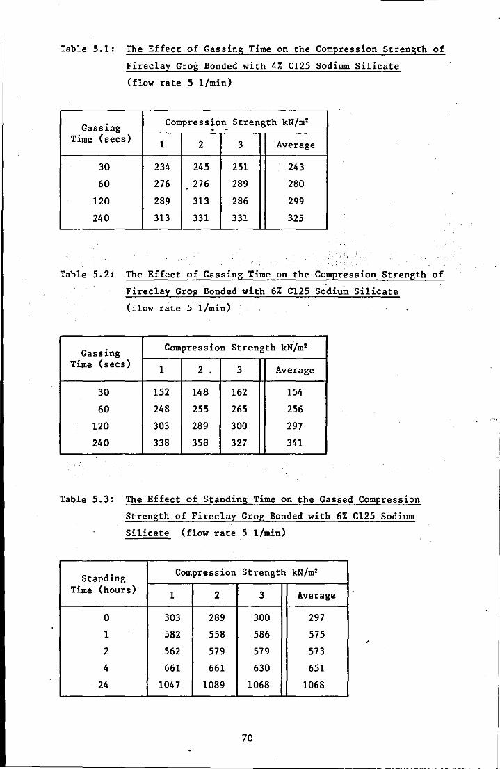
Table 5.1: The Effect of Gassing Time on the Compression Strength of
Fireclay Grog Bonded with 4% C125 Sodium Silicate
(flow rate 5 I/min)
Gassing Compress~o~ Strength kN/m'
Time (secs) 1 2 3 Average
30 234 245 251 243
60 276 276 289 280
120 289 313 286 299
240 313 331 331 325
Table 5.2: The Effect of Gassing Time on the Compr~ssion Strength of
Fireclay Grog Bonded with 6% C125 Sodium Silicate
(flow rate 5 I/min)
Gassing Compression Strength kN/m'
Time (secs) 1 2 . 3 Average
30 152 148 162 154
60 248 255 265 256
120 303 289 300 297
240 338 358 327 341
Table 5.3: The Effect of Standing Time on the Gassed Compression
Strength of Firec1ay Grog Bonded with 6% C125 Sodium
Silicate (flow rate 5 I/min)
Standing Compression Strength kN/m'
Time (hours) 1 2 3 Average
0 303 289 300 297
1 582 558 586 575 /
2 562 579 579 573
4 661 661 630 651
24 1047 1089 1068 1068
70
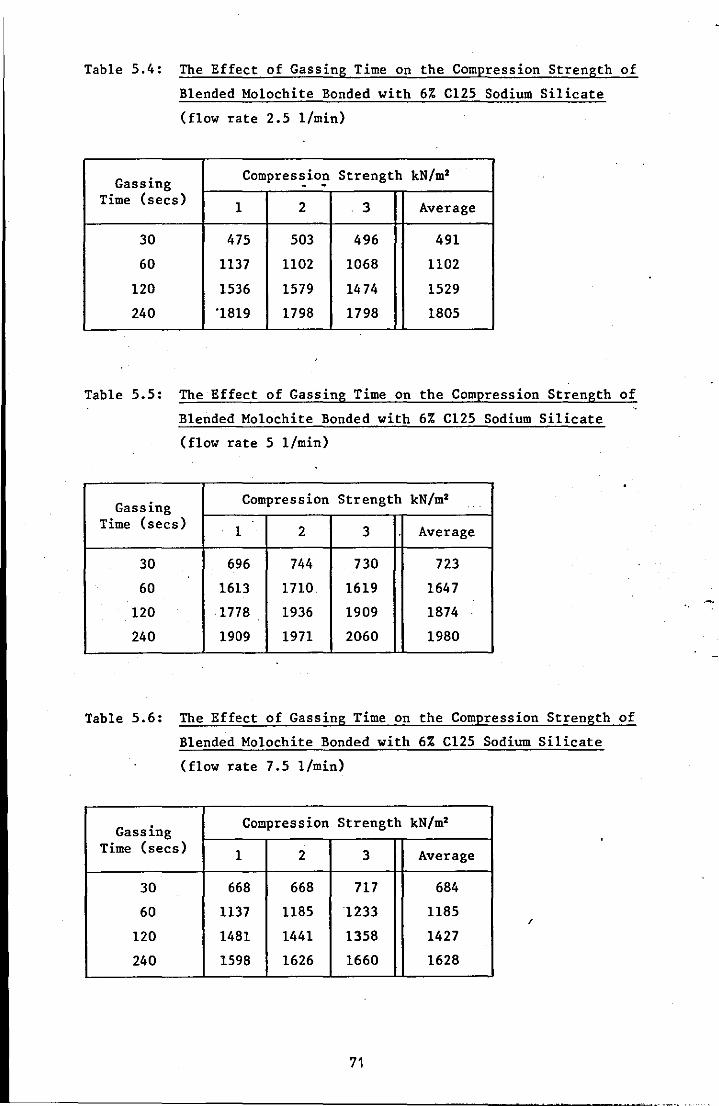
Table 5.4: The Effect of Gassing Time on the Compression Strength of
Blended Mo1ochite Bonded with 6% C125 Sodium Silicate
(flow rate 2.5 l/min)
Gassing Compress,i0!l Strength kN/m'
Time (secs) 1 2 3 Average
30 475 503 496 491
60 1137 1102 1068 1102
120 1536 1579 1474 1529
240 '1819 1798 1798 1805
Table 5.5: The Effect of Gassing Time On the Compression Strength of
Blended Mo1ochite Bonded with 6% C125 Sodium Silicate
(flow rate 5 l/min)
Gassing Compression Strength kN/m'
Time (secs) 1 2 3 Average
30 696 744 730 723
60 1613 1710. 1619 1647
120 ·1778 1936 1909 1874
240 1909 1971 2060 1980
Table 5.6: The Effect of Gassing Time On the Compression Strength of
Blended Mo1ochite Bonded with 6% C125 Sodium Silicate
(flow rate 7.5 l/min)
Gassing Compression Strength kN/m'
Time (secs) 1 2 3 Average
30 668 668 717 684
60 1137 1185 1233 1185 /
120 1481 1441 1358 1427
240 1598 1626 1660 1628
71
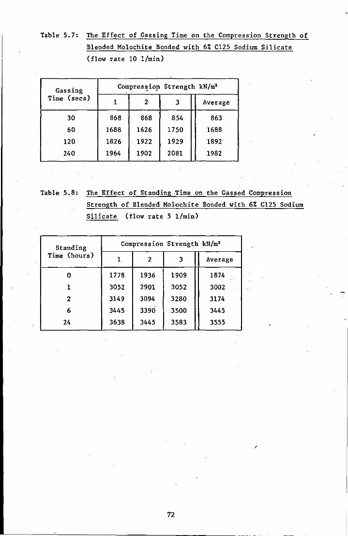
Table 5.7: The Effect of Gassing Time on the Compression Strength of
Blended Mo1ochite Bonded with 6% C125 Sodium Silicate
(flow rate 10 l/min)
Gassing Compres'!.io,!l Strength kN/m2
Time (secs) 1 2 3 Average
30 868 868 854 863
60 1688 1626 1750 1688
120 1826 1922 1929 1892
240 1964 1902 2081 1982
Table 5.8: The Effect of Standing .Time on the Gassed Compression
Strength of Blended Mo1ochite Bonded with 6% C125 Sodium
Silicate (flow rate 5 l/min)
Standing Compression Strength kN/m2
Time (hours) 1 2 3 Average
0 1778 1936 1909 1874
1 3052 2901 3052 3002
2 3149 3094 3280 3174
6 3445 3390 3500 3445
24 3638 3445 3583 3555
I
72
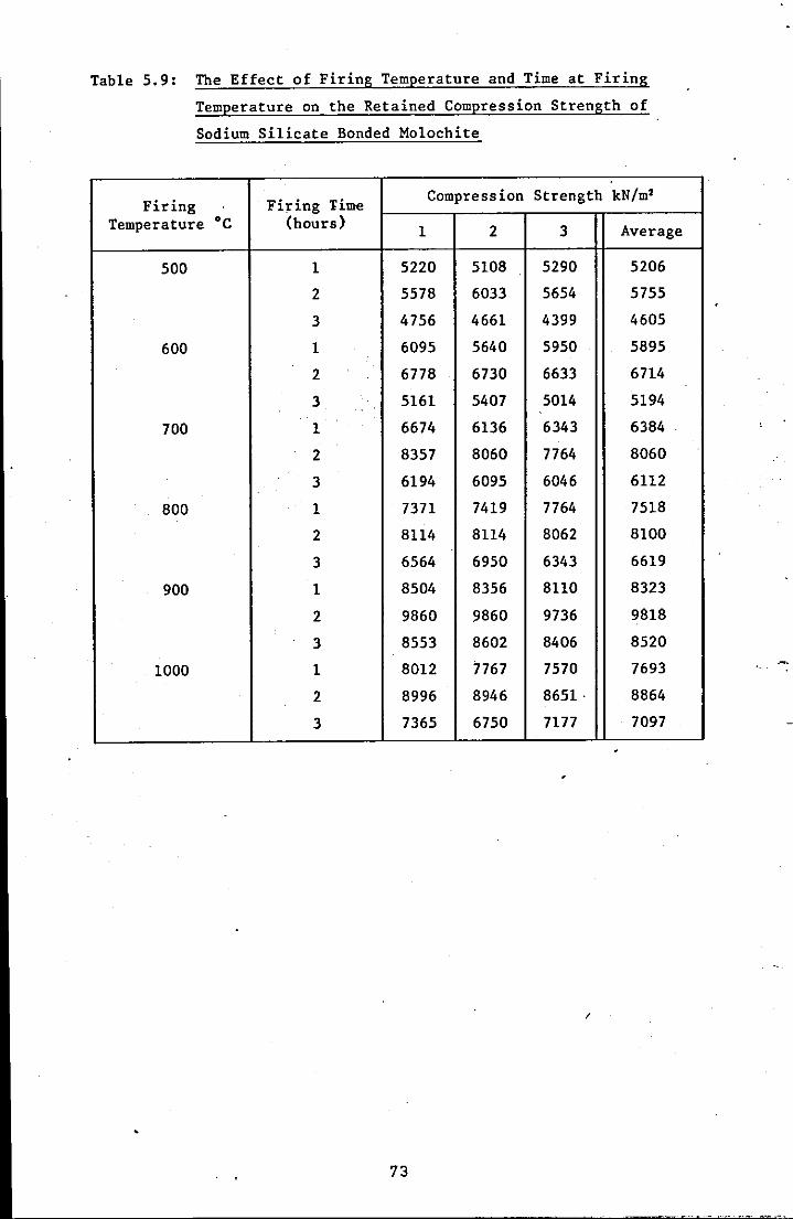
Table 5.9: The Effect of Firing Temperature and Time at Firing
Temperature on the Retained Compression Strength of
Sodium Silicate Bonded Mo1ochite
Firing Firing Time Compression Strength kN/m2
Temperature ·C (hours) 1 2 3 Average
500 1 5220 5108 5290 5206
2 5578 6033 5654 5755
3 4756 4661 4399 4605
600 1 6095 5640 5950 5895
2 6778 6730 6633 6714
3 5161 5407 5014 5194
700 1 6674 6136 6343 6384
2 8357 8060 7764 8060
3 6194 6095 6046 6112
800 1 7371 7419 7764 7518
2 8114 8114 8062 8100
3 6564 6950 6343 6619
900 1 8504 8356 8110 8323
2 9860 9860 9736 9818
3 8553 8602 8406 8520
1000 1 8012 7767 7570 7693
2 8996 8946 8651· 8864
3 7365 6750 7177 7097
I
73
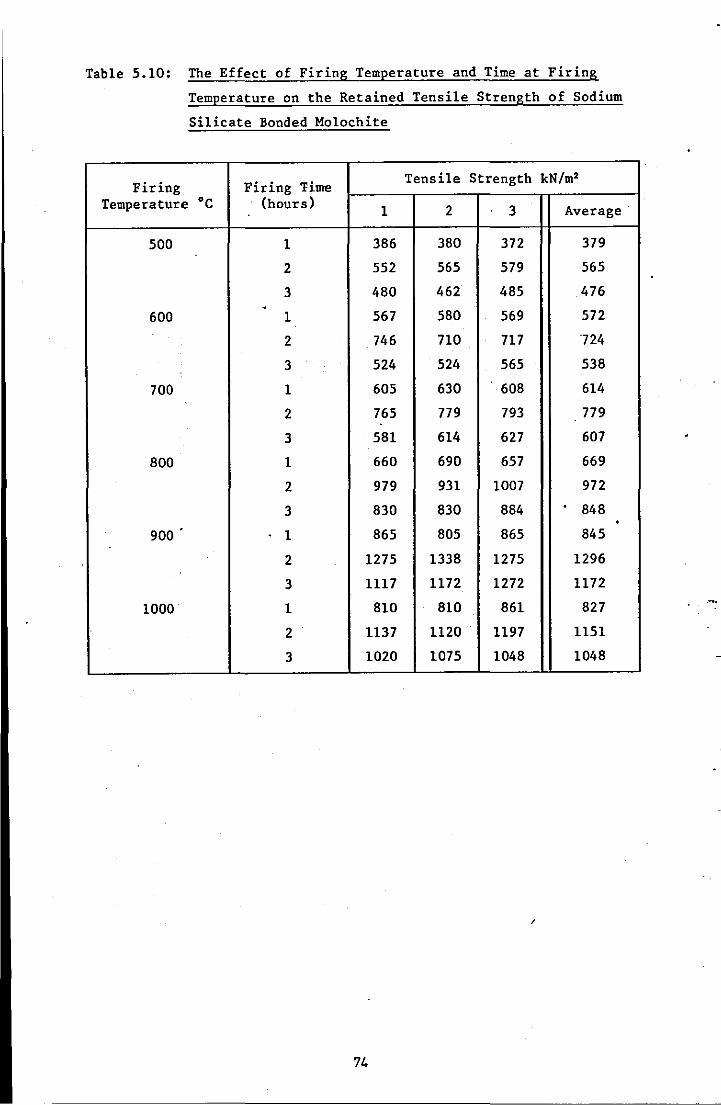
Table 5.10: The Effect of Firing Temperature and Time at Firing
Temperature on the Retained Tensile Strength of Sodium
Silicate Bonded Molochite
Firing Firing lime Tensile Strength kN/m2
Temperature ·c (hours) 1 2 3 Average·
500 1 386 380 372 379
2 552 565 579 565
3 480 462 485 476 . 600 1 567 580 569 572
2 746 710 717 724
3 524 524 565 538
700 1 605 630 608 614
2 765 779 793 779
3 581 614 627 607
800 1 660 690 657 669
2 979 931 1007 972
3 830 830 884 . 848 . 900
. 1 865 805 865 845
2 1275 1338 1275 1296
3 1117 1172 1272 1172
1000 1 810 810 861 827
2 1137 1120 1197 1151
3 1020 1075 1048 1048
/
74
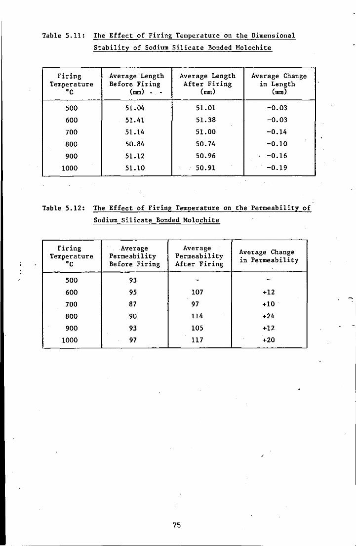
Table 5.11: The Effect of Firing Temperature on the Dimensional
Stability of Sodium Silicate Bonded Molochite
Firing Average Length Average Length Average Change Temperature Before Firing After Firing in Length
·C (mm) . . (mm) (mm)
500 51.04 51.01 -0.03
600 51.41 51.38 -0.03
700 51.14 51.00 -0.14
800 50.84 50.74 -0.10
900 51.12 50.96 -0.16
1000 51.10 50.91 -0.19
Table 5.12: The Effect of Firing Temperature on the Permeability of
Sodium Silicate Bonded Molochite
Firing .Average Average Average Change Temperature Permeability Permeability in Permeability ·C Before Firing After Firing
500 93 - -600 95 107 +12
700 87 97 +10
800 90 114 +24
900 93 105 +12
1000 97 117 +20
/
75
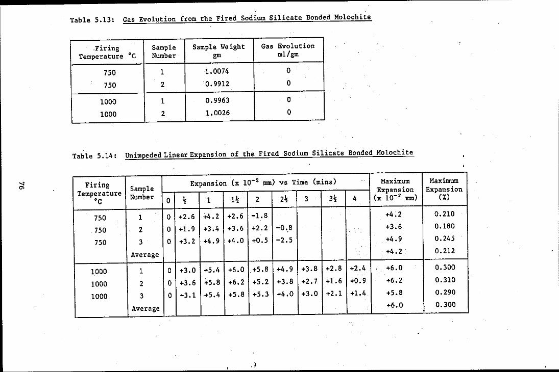
Table 5.13: Gas Evolution from the Fired Sodium Silicate Bonded Mo1ochite
.Firing .
Sample Sample Weight Gas Evolution Temperature ·c Number gm m1/gm
750 1 1.0074 0
750 2 0.9912 0
1000 1 0.9963 0
1000 2 1.0026 0
Table 5.14: Unimpeded Linear Expansion of the Fired Sodium Silicate Bonded Mo1ochite
Firing Sample Expansion (x 10- 2 mm) vs Time (mins) Maximum Maximum
Temperature Expansion Expansion
·c Number 0 % 1 1% 2 2% 3 3% 4 (x 10-2 mm) (%)
750 1 0 +2.6 +4.2 +2.6 -1.8 +4:2 0.210
750 2 0 +1.9 +3.4 +3.6 +2.2 -0.,8 +3.6 0.180
750 3 0 +3.2 +4.9 +4.0 +0.5 -2.5 +4.9 0.245
Average . +4.2 0.212 .
1000 1 0 +3.0 +5.4 +6.0 +5.8 +4.9 +3.8 +2.8 +2.4 +6.0 0.300
1000 2 0 +3.6 +5.8 +6.2 +5.2 +3.8 +2.7 +1.6 +0.9 +6.2 0.310
1000 3 0 +3.1 0+5.4 +5.8 +5.3 +4.0 +3.0 +2.1 +1.4 +5.8 0.290
Average +6.0 0.300
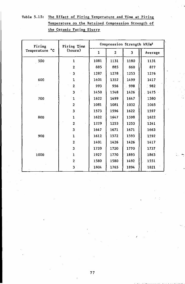
Table 5.15: The Effect of Firing Temperature and Time at Firing
Temperature on the Retained Compression Strength of
the Ceramic Facing Slurry
Firing Firing Time Compression Strength kN/m2
Temperature ·C (hours) 1 2 3 Average
500 1 1081 1131 1180 1131
2 885 885 860 877
3 1287 1278 1253 1276
600 1 1401 1352 1499 1417
2 993 956 998 982
3 1450 1548 1426 1475
700 1 1622 1499 1647 1580
2 1081 1081 1032 1065
3 1573 1596 1622 1597
800 1 1622 1647 1598 1622 I
2 1229 1253 1253 1241
3 1647 1671 1671 1663
900 1 1612 1572 1593 1592
2 1401 1426 1426 1417
3 1720 1720 1770 1737
1000 1 1927 1770 1893 1863
2 1580 1580 1492 1551
3 1804 1765 1894 1821
/
77
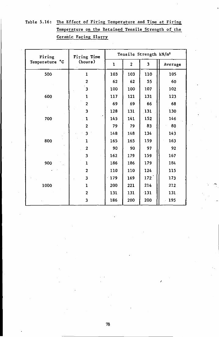
Table 5.16: The Effect of Firing Temperature and Time at Firing
Temperature on the Retained Tensile Strength of the
Ceramic Facing Slurry
Firing Fidng 'Fime Tensile Strength kN/m2
Temperature ·C (hours) 1 2 3 Average
500 1 103 103 110 105
2 62 62 55 60
3 100 100 107 102
600 1 117 121 131 123
2 69 69 66 68
3 128 131 131 . 130
700 1 145 141 152 146
2 79 79 83 80
3 148 148 134 143
800 1 165 165 159 163
2 90 90 97 92
3 162 179 159 167
900 1 186 186 179 184
2 110 110 124 115
3 179 169 172 173
1000 1 200 221 214 212
2 131 131 131 131
3 186 200 200 195
I
79

Table 5.17: The Effect of Firing Temperature on the Dimensional
Stability of the Ceramic Facing Slurry
Firing Average Length Average Length Average Change Temperature Before Firing After Firing in Length
DC (mm) - - (mm) (mm)
500 5L39 51.40 +0.01
600 51.47 51. 53 +0.06
700 51.32 51.35 +0.03
BOO 51.28 51.30 +0.02
900 51.25 51.30 +0.05
1000 51.30 51.32 +0.02
Table 5.1B: The Effect of Firing Temperature on the Permeability of
the Ceramic Facing Slurry
Firing Average Average Average Change Temperature Permeability Permeability in Permeability DC Before Firing After Firing
500 4.0 - -600 3.4 3.7 +0.3
700 4.1 3.B -0.3
BOO • 4.0 4.6 +0.6
900 5.1 3.9 -1.2
1000 4.7 4.2 -0.5
I
79
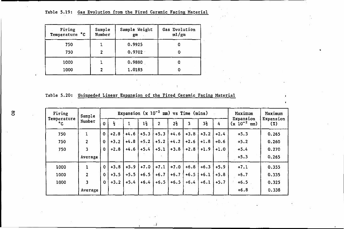
CD o
Table 5.19: Gas Evolution from the Fired Ceramic Facing Material
Firing Sample Sample Weight Gas Evolution Temperature ·C Number gm m1/gm
750 1 0.9925 0
750 2 0.9702 0
1000 1 0.9880 0
1000 2 1.0185 0
Table 5.20: Unimpeded Linear Expansion of the Fired Ceramic Facing Material
Firing Sample Expansion (x 10- 2 mm) vs Time (mins) Maximum Temperature Expansion
·C Number 0 % 1 1% 2 2% 3 3% 4 (x 10- 2 mm)
750 1 0 +2.8 +4.6 +5.3 +5.3 +4.6 +3.8 +3.2 +2.4 +5.3
750 2 0 +3.2 +4.8 +5.2 +5.2 +4.2 +2.6 +1.8 +0.6 +5.2
750 3 0 +2.8 +4.6 +5.4 +5.1 +3.8 +2.8 +1.9 +1.0 +5.4
Average +5.3
1000 1 0 +3.8 +5.9 +7.0 +7.1 +7.0 +6.8 +6.3 +5.9 +7.1
1000 2 0 +3.5 +5.5 +6.5 +6.7 +6.7 +6.5 +6.1 +5.8 +6.7
1000 3 0 +3.2 +5.4 +6.4 +6.5 +6.5 +6.4 +6.1 +5.7 +6.5
Average +6.8
. !
•
Maximum Expansion
0:)
0.265
0.260
0.270
0.265
0.355
0.335
0.325
0.338
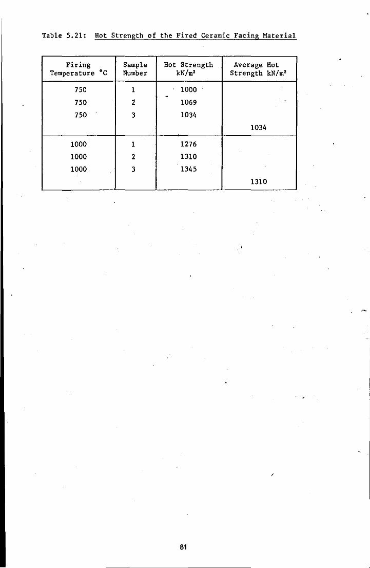
Table 5.21: Hot Strength of the Fired Ceramic Facing Material
Firing Sample Hot Strength Average Hot Temperature ·C Number kN/m' Strength kN/m'
750 1 1000 -
750 2 1069
750 3 1034
1034
1000 1 1276
1000 2 1310
1000 3 1345
1310
/
81
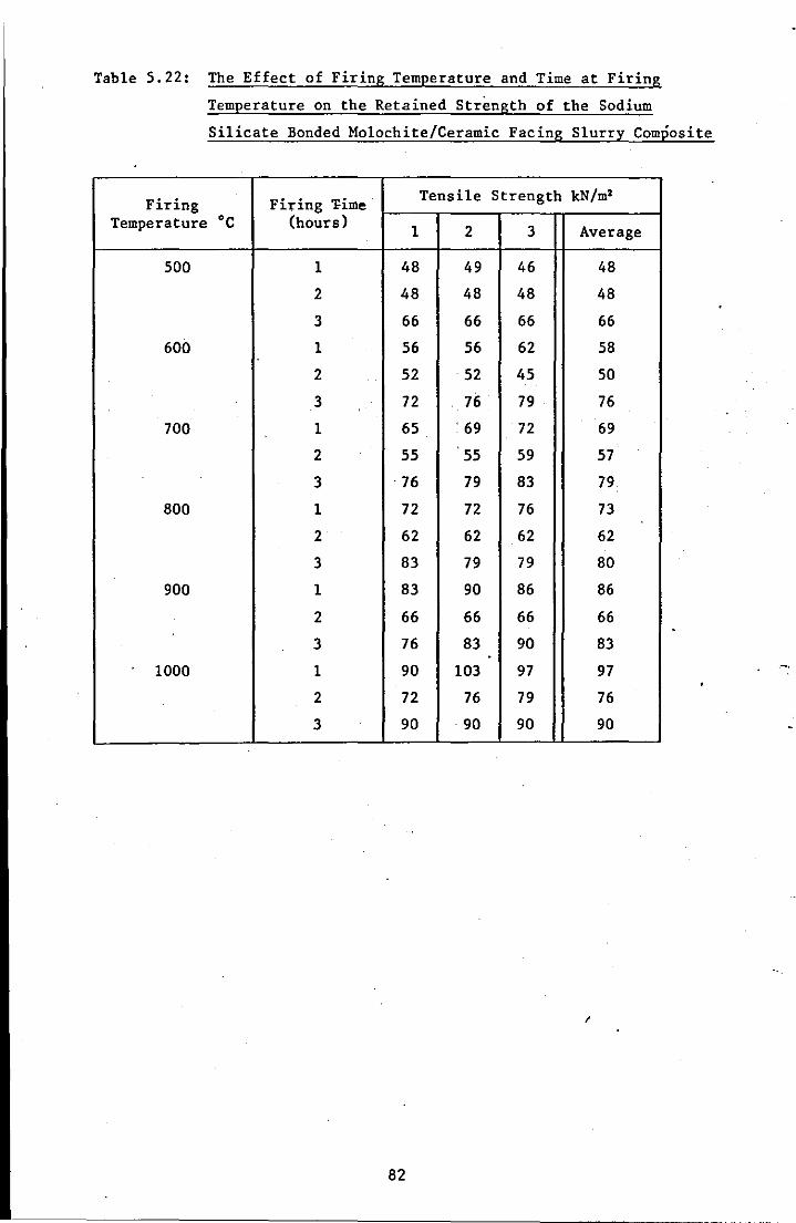
Table 5.22: The Effect of Firing Temperature and Time at Firing
Temperature on the Retained Strength of the Sodium
Silicate Bonded Mo10chite/Ceramic Facing Slurry Composite
Firing Firing "I'ime' Tensile Strength kN/m2
Temperature ·C (hours) 1 2 3 Average
500 1 48 49 46 48
2 48 48 48 48
3 66 66 66 66
600 1 56 56 62 58
2 52 52 45 50
3 72 76 79 76
700 1 65 ' 69 72 69
2 55 55 59 57
3 ·76 79 83 79
800 1 72 72 76 73
2 62 62 62 62
3 83 79 79 80
900 1 83 90 86 86
2 66 66 66 66
3 76 83 90 83 . 1000 1 90 103 97 97
2 72 76 79 76
3 90 90 90 90
/
82
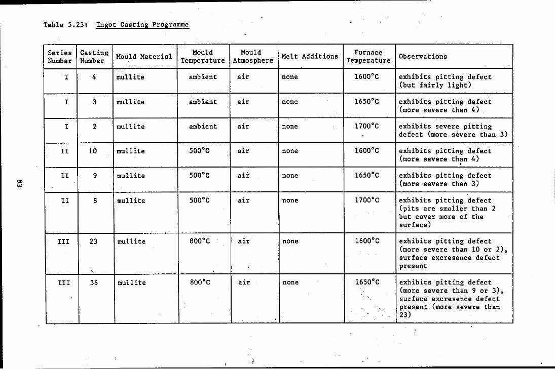
(J>
'"
Table S.23: Ingot Casting Programme
Series Casting Mould Material Mould Number Number Temperature
I 4 mullite ambient
I 3 mullite ambient
I 2 mullite ambient
Il 10 mullite SOO'C
Il 9 mullite SOO'C
Il B mullite SOO'C
III 23 mullite BOO'C
,
III 36 mullite BOO'C
Mould Melt Additions Furnace Observations Atmosphere Temperature
air none l600'C exhibits pitting defect (but fairly light)
air none l6S0'C exhibits pitting defect (more severe than 4)
air none l700'C exhibits severe pitting defect (more severe than 3)
air none l600'C exhibits pitting defect (more severe than 4)
• air none l6S0'C exhibits pitting defect
(more severe than 3)
air none l700'C exhibits pitting defect (pits are smaller than 2 but cover more of the surface)
air none l600'C exhibits pitting defect (more severe than 10 or 2), surface excresence defect present
air none l650'C exhibits pitting defect (more severe than 9 or 3), surface excresence defect present (more severe than 23)

Table 5.23 cont
Series Casting Mould Material Mould Mould Melt Additions Furnace Observations Number Number Temperature Atmosphere Temperature
III 39 mullite 800·C air none . l700·C exhibits pitting defect (more severe than 8 or 2), surface excresence defect present
IV 41 mullite ambient nitrogen none l600·C surface free of pitting defect, some surface excresence
IV 50 mullite ambient nitrogen none l650·C surface free of pitting 4- defect, surface excresence
"-3 defect present'
IV 46 mullite ambient nitrogen none l700·C surface free of pitting defect, surface excresence defect present
V 42 mullite ambient air deoxidiser l650·C pitting defect present 0.25 wt% Stellagen 1
V 34 mullite ambient air deoxidiser . l650·C areas of pitting defect, 0.50 wt% some areas free, some areas Stellagen 1 of surface excresence
V 37 mullite' ambient air deoxidiser l650·C surface generally free of 0.75 wt% pitting defect, but Stellagen 1 increased surface
excresences
, )
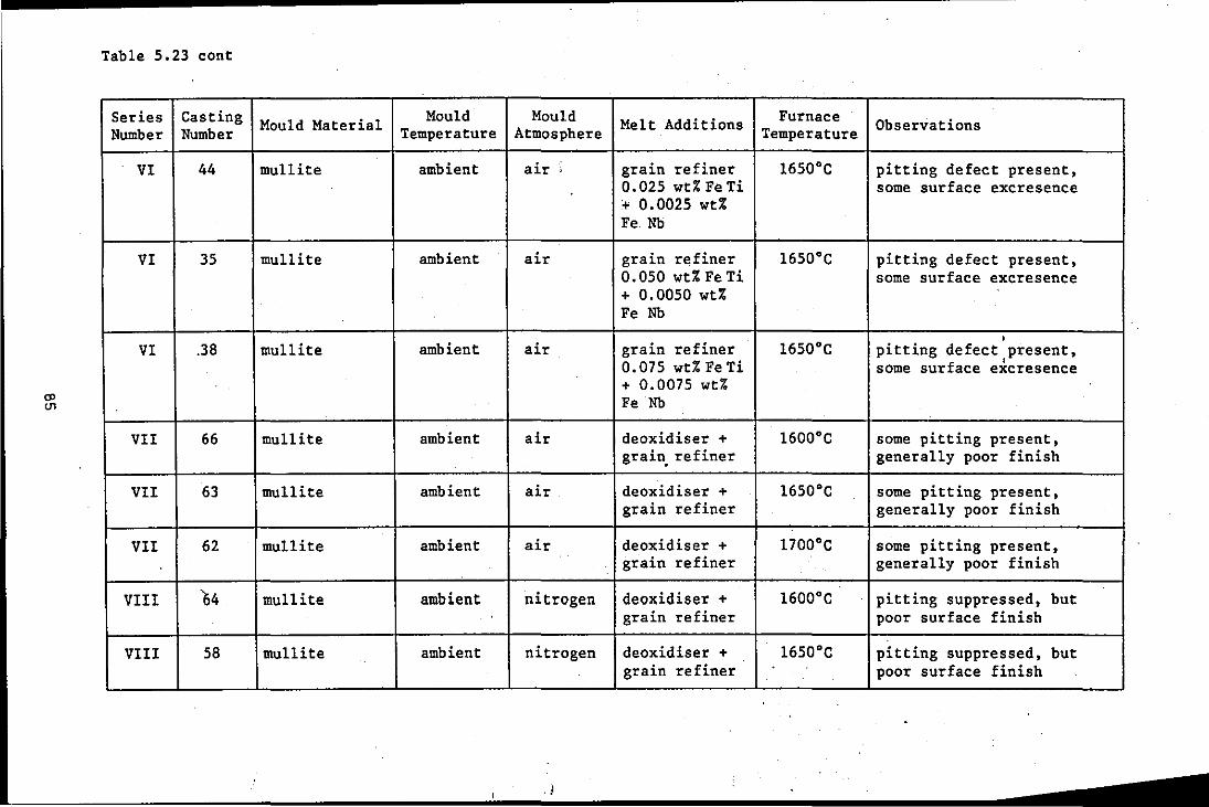
CJ> 111
Table 5.23 cont
Series Casting Number Number
VI 44
VI 35
VI .38
VII 66
VII 63
VII 62
VIII 64
VIII 58
Mould Material Mould Temperature
mullite ambient
mullite ambient
..
mullite ambient
mullite ambient
•
mullite ambient
mullite ambient
mullite ambient
mullite ambient
Mould Melt Additions Furnace Observations Atmosphere Temperature
air' grain refiner l650·C pitting defect present, 0.025 wt% Fe Ti some surface excresence + 0.0025 wt% Fe. Nb
air grain refiner l650·C pitting defect present, 0.050 wt% Fe Ti some surface excresence + 0.0050 wt% Fe Nb
• air grain refiner l650·C pitting defect present, 0.075 wt% Fe Ti some surface excresence + 0.0075 wt% Fe Nb
air deoxidiser + l600·C some pitting present, grain. refiner generally poor finish
air deoxidiser + l650·C some pitting present, grain refiner generally poor finish
air deoxidiser + l700·C some pitting present, grain refiner generally poor finish
nitrogen deoxidiser + 1600·C pitting suppressed, but grain refiner poor surface finish
nitrogen deoxidiser + 1650·C pitting suppressed, but grain refiner poor surface finish
. J
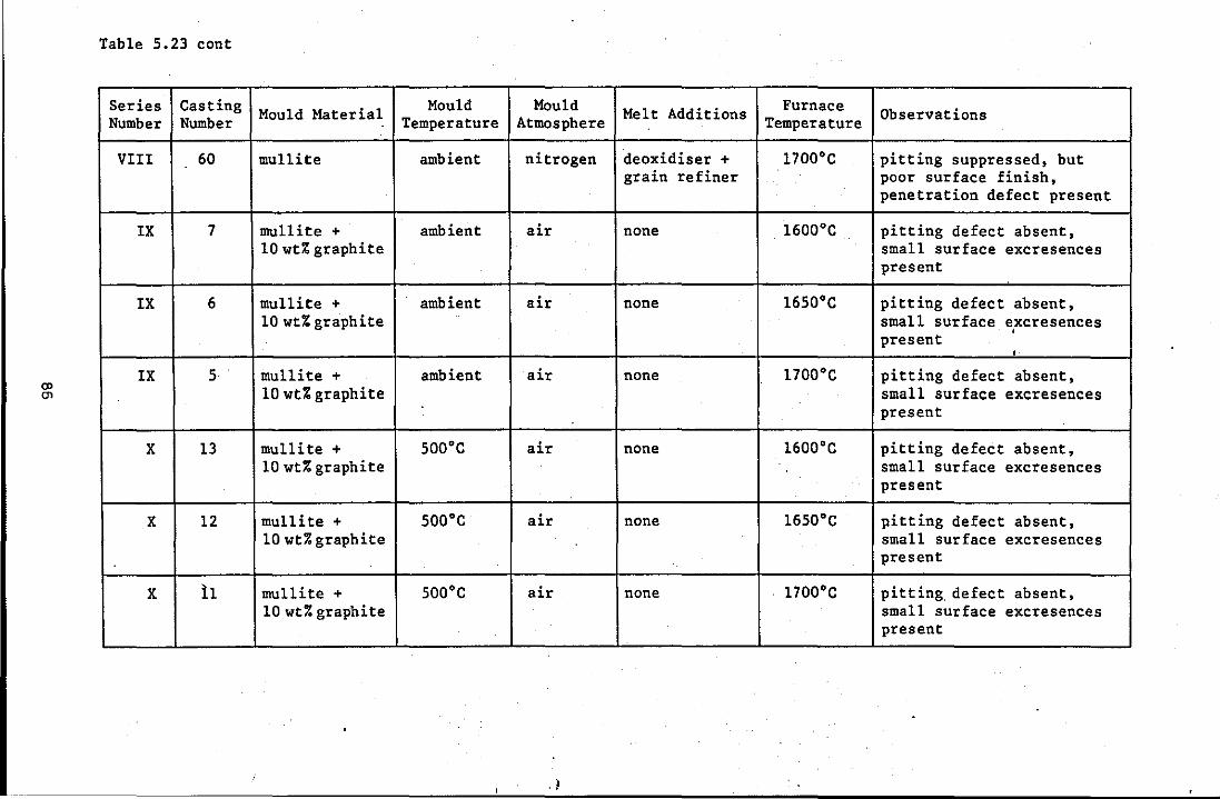
Cl> Cl>
Table 5.23 cont
Series Casting Number Number
VIII 60
IX 7
IX 6
IX 5 <
X 13
X 12
X 11
Mould Material Mould Temperature
mullite ambient
mullite + ambient 10 wt% graphite
mullite + ambient 10 wt% graphite
mullite + ambient 10 wd graphite
mullite + 500·C 10 wt% graphite
mullite + 500·C 10 wt% graphite
mullite + 500·C 10 wt% graphite
Mould Melt Additions Furnace Observations Atmosphere Temperature
nitrogen deoxidiser + 1700·C pitting suppressed, but grain refiner poor surface finish,
penetration defect present
air none 1600·C pitting defect absent, small surface excresences
<
present
air none 1650·C pitting defect absent, small surface excresences , present ,
air none 1700·C pitting defect absent, small surface excresences present
air none 1600·C pitting defect absent, small surface excresences present
<
air none 1650·C pitting defect absent, small surface excresences
« present
air none 1700·C pitting. defect absent, small surface excresences present
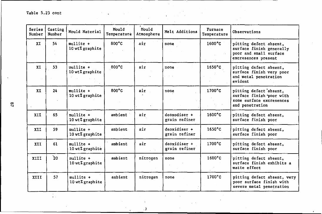
Table 5.23 cont
. Series Casting Mould Material Mould Mould Melt Additions Furnace. Observations Number Number Temperature Atmosphere Temperature
XI 54 mullite + BOOoe air none 1600 0 e pitting defect absent, 10 wt% graphite sur face finish generally
poor and small surface . excresences present
XI 53 mullite + BOOoe air none 16500 e pitting defect absent, 10 wt% graphite surface finish very poor
and metal penetration evident
XI 24 mullite + BOOoe air none 17000 e pitting defect 'absent, 10 wt% graphite surface finish 'poor with
some surface excresences and penetration
XII 65 mu11ite + ambient air deoxodiser + 16000 e pitting defect absent, 10 wt% graphite grain refiner surface finish poor
XII 59 mullite + ambient air deoxidiser + 1650 0 e pitting defect absent, 10 wt% graphite grain refiner surface finish poor
XII 61 mullite + ambient air deoxidiser + 1700 0 e pitting defect absent, 10 wt% graphite grain refiner surface finish poor
XIII 20 mullite + ambient nitrogen none 16000 e pitting defect absent, 10 wt% graphite surface finish exhibits a
matte effect
XIII 57 mullite + ambient nitrogen none 17000 e pitting defect absent, very 10 wt% graphite poor surface finish with
severe.metal penetration
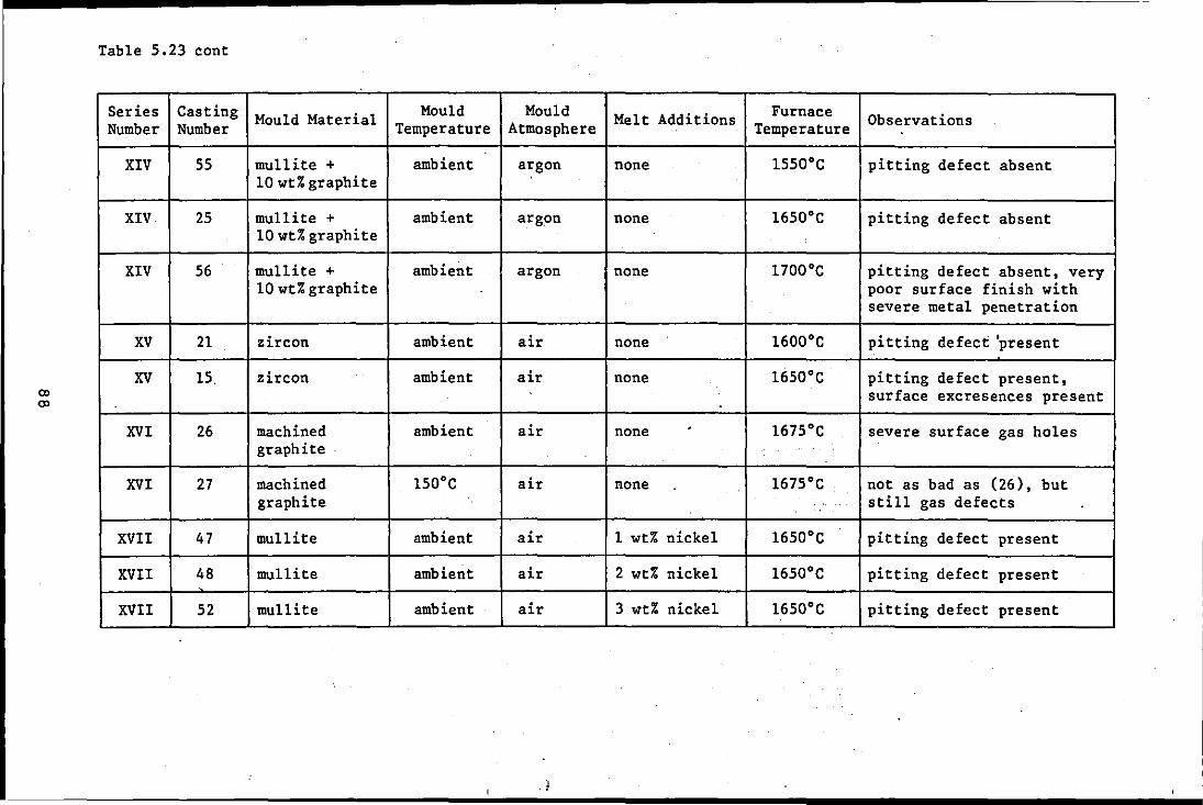
CD CD
Table 5.23 cont
Series Casting Number Number
XIV 55
XIV 25
XIV 56
XV 21
XV 15.
XVI 26
XVI 27
XVII 47
XVII 48
XVII 52
Mould Material Mould Temperature
mullite + ambient 10 wt% graphite
mullite + ambient 10 wt% graphi te
mullite + ambient 10 wt% graphite
zircon ambient
zircon ambient
machined ambient graphite .
machined l50'C graphite
mullite ambient
mullite ambient
mullite ambient
Mould Melt Additions Furnace Observations Atmosphere Temperature
argon none 1550'C pitting defect absent
argon none 1650'C pitting defect absent
argon none l700'C pitting defect absent, very poor surface finish with severe metal penetration
air none l600'C pitting defect 'present
air none l650'C pitting defect present, surface excresences present
air none . l675'C severe surface gas holes .
air none l675'C not as bad as (26), but still gas defects
air 1 wt% nickel l650'C pitting defect present
air 2 wt% nickel I 1650'C pitting defect present
air 3 wt% nickel l650'C pitting defect present
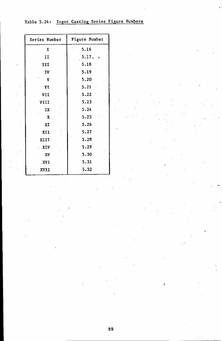
Table 5.24: Ingot Casting Series Figure Numbers
Series Number Figure Number
I 5.16
II 5.17. . III 5.18
IV 5.19
V 5.20
VI 5.21
VII 5.22
VIII 5.23
IX 5.24
X 5.25
XI 5.26
XII 5.27
XIII 5.28
XIV 5.29
XV 5.30
XVI 5.31
XVII 5.32
I
89
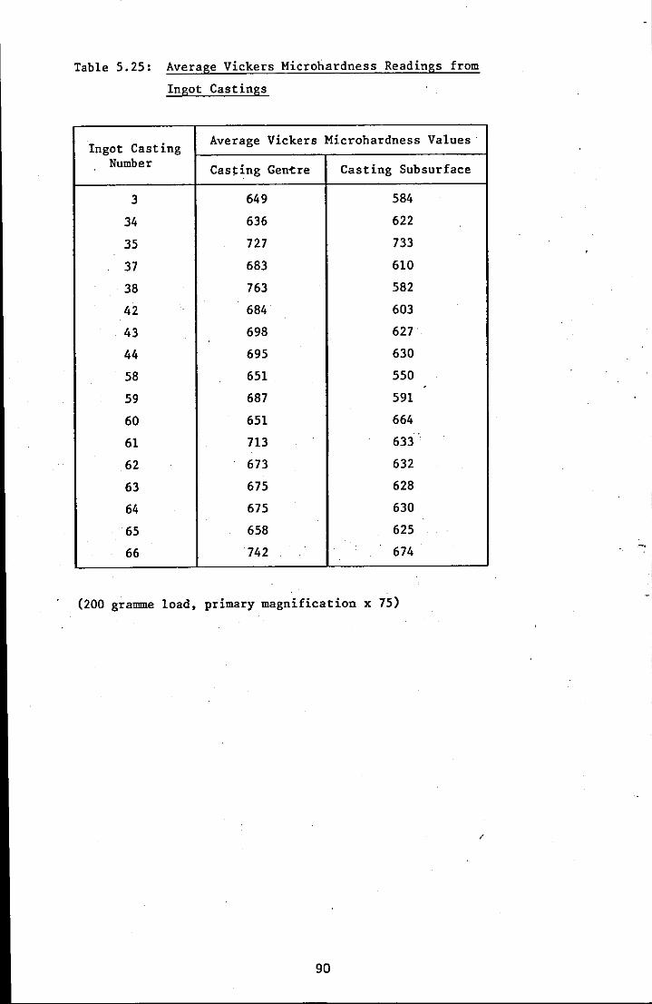
Table 5.25: Average Vickers Microhardness Readings from
Ingot Castings
Ingot Casting Average Vickers Microhardness Values
Number Cas~ing Geni:re Casting Subsurface
3 649 584
34 636 622
35 727 733
37 683 610
38 763 582
42 684 603
43 698 627
44 695 630
58 651 550
59 687 591
60 651 664
61 713 633·
62 673 632
63 675 628
64 675 630 .
65 658 625
66 742 674
(200 gramme load, primary magnification x 75)
90
/
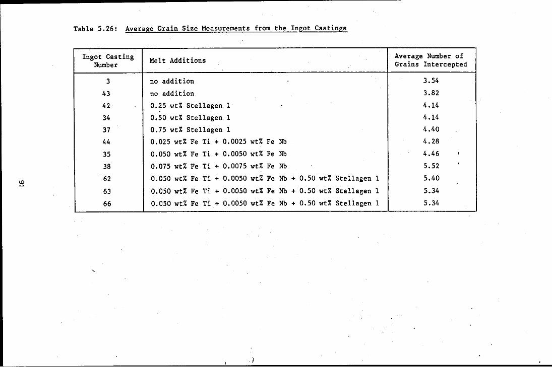
Table 5.26: Average Grain Size Measurements from the Ingot Castings
Ingot Casting Melt Additions Average Number of
Number Grains Intercepted
3 no addition 3.54
43 no addition 3.82
42 0.25 wt% Stellagen 1 . 4.14
34 0.50 wt% Stellagen 1 4.14
37 0.75 wt% Ste11agen 1 4.40
44 0.025 wt% Fe Ti + 0.0025 wt% Fe Nb 4.28
35 0.050 wt% Fe Ti + 0.0050 wt% Fe Nb 4.46 ,
38 0.075 wt% Fe Ti + 0.0075 wt% Fe Nb 5.52 •
. 62 0.050 wt% Fe Ti + 0.0050 wt% Fe Nb + 0.50 wt% Stellagen 1 5.40
63 0.050 wt% Fe Ti + 0.0050 wt% Fe Nb + 0.50 wt% Stellagen 1 5.34
66 0.050 wt% Fe Ti + 0.0050 wt% Fe Nb+ 0.50 wt% Stellagen 1 5.34
,
!
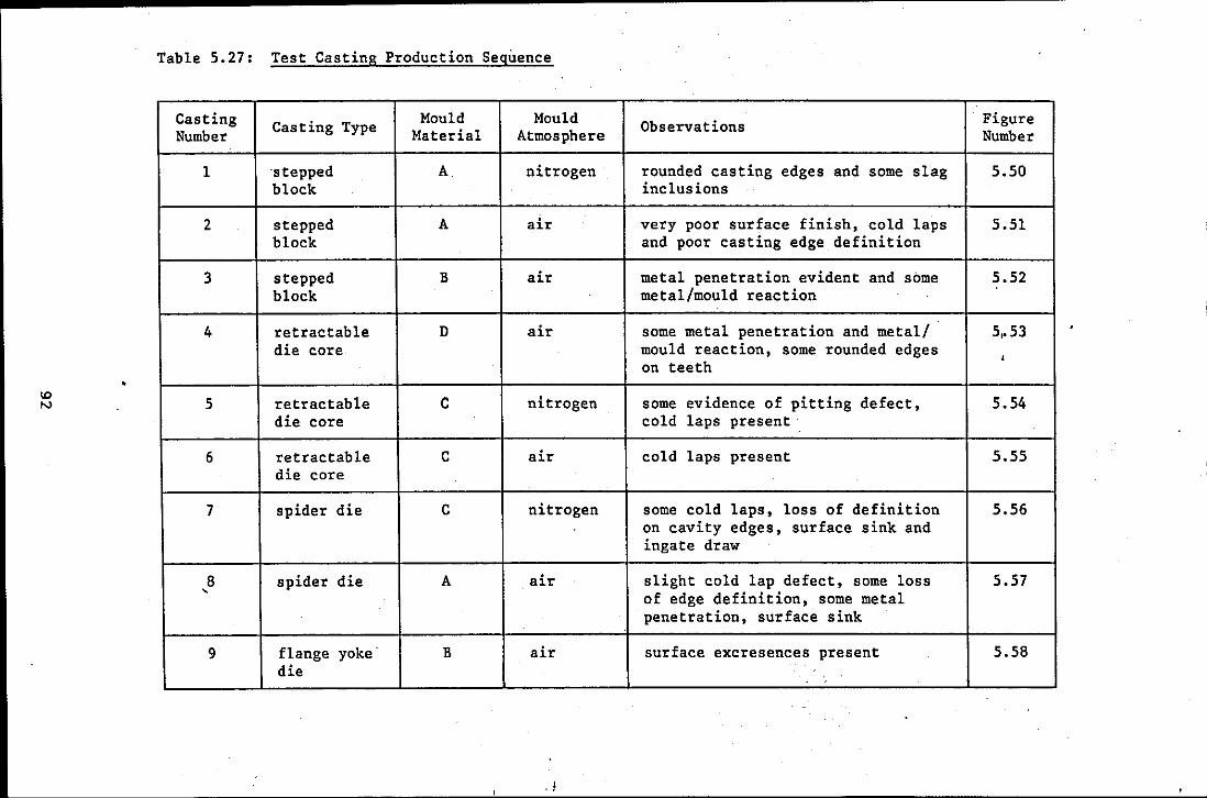
Table 5.27: Test Casting Production Sequence
Casting Casting Type Mould Mould Observations Figure Number Material Atmosphere Number
1 'stepped A nitrogen' rounded casting edges and some slag 5.50 block inclusions
2 stepped A air very poor surface finish, cold laps 5.51 block and poor casting edge definition
3 stepped B air metal penetration evident and some 5.52 block metal/mould reaction
4 retractable D air some metal penetration and metal/ 5,.53 die core mould reaction, some rounded edges ,
on teeth
5 retractable C nitrogen some evidence of pitting defect, 5.54 die core cold laps present
6 retractable C air cold laps present 5.55 die core
7 spider die C nitrogen some cold laps, loss of definition 5.56 on cavity edges, surface sink and ingate draw
8 spider die A air slight cold lap defect, some loss 5.57 , of edge definition, some metal
. penetration, surface sink
9 flange yoke B air surface excresences present 5.58 die
. 1
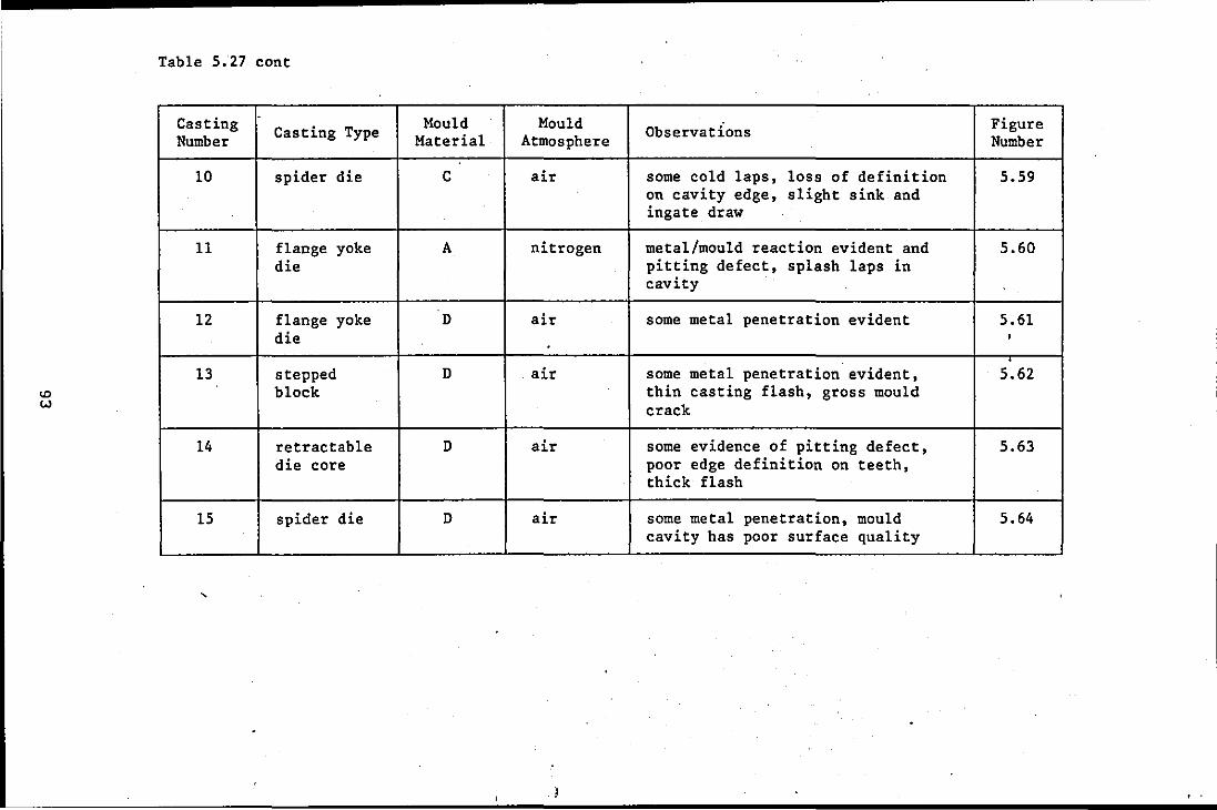
ID W
Table 5.27 cont
Casting Casting Type Number
10 spider die
11 flange yoke die
12 flange yoke die
13 stepped block
14 retractable die core
15 spider die
Mould Mould Material Atmosphere
C air
A nitrogen
D air .
D air
D air
D air
Observations Figure Number
some cold laps, loss of definition 5.59 on cavity edge, slight sink and ingate draw
metal/mould reaction evident and 5.60 pitting defect, splash laps in cavity
some metal penetration evident 5.61 •
some metal penetration evident, 5.62 thin casting flash, gross mould crack
some evidence of pitting defect, 5.63 poor edge definition on teeth, thick flash
some metal penetration, mould 5.64 cavity has poor surface quality

Table 5.28: Mould Facing Material Specifications
Mould Material Mould Facing Material Specification (wt%)
and Grade A B C D
-8 + 16 mullite 25- - 25 25 25
-30 mullite 25 25 25 25
-100 mullite 50 40 25 20.
-300 mullite 25 20
-100 graphite 10 10
/
94
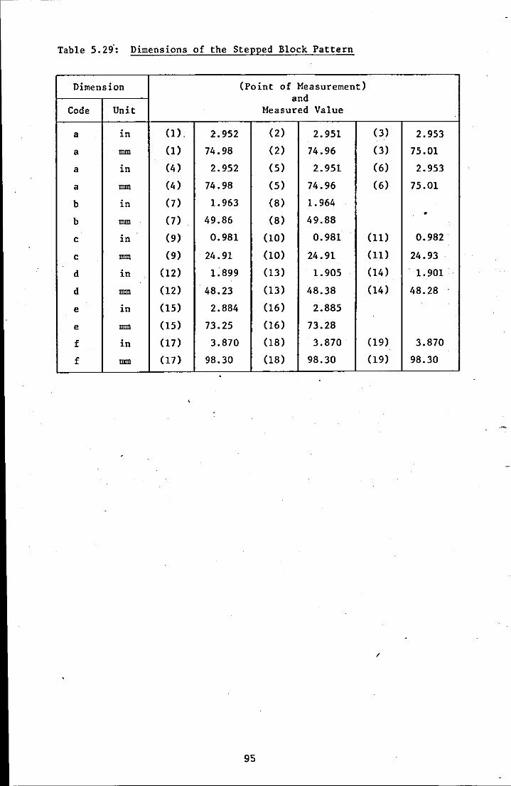
Table 5.29': Dimensions of the Stepped Block Pattern
Dimension (Point of Measurement) and
Code Unit Measured Value
a in (1) , 2.952 (2) 2.951 (3) 2.953
a mm (1) 74.98 (2) 74.96 (3) 75.01
a in (4 ) 2.952 (5) 2.951 ( 6) 2.953
a mm (4) 74.98 (5) 74.96 (6) 75.01
b in (7) 1.963 (8) 1.964 . b mm (7) 49.86 (8) 49.88
c in (9) 0.981 (10) 0.981 (11) 0.982
c mm (9) 24.91 (10) 24.91 (11) 24.93
d in (12) 1.899 (13) 1.905 (14) 1.901
d mm (12) 48.23 (13) 48.38 (14) 48.28
e in (15) 2.884 (16) 2.885
e mm (15) 73.25 (16) 73.28
f in (17) 3.870 (18) 3.870 (19) 3.870
f mm (17) 98.30 (18) 98.30 (19) 98.30
/
95

Table 5.30: Dimensions of Stepped Block Casting 1
Dimension (Point of Measurement) and
Code Unit Measured Value
a in (1). 2.927 (2) 2.920 (3) 2.926
a mm (1) 74.35 (2) 74.17 (3) 74.32
a in (4) 2.915 (5) 2.918 . (6) 2.915 .
a mm (4) 74.04 (5) 74.12 (6) 74.04
b in 0) 1.941 (8) 1.942
b mm (7) 49.30 (8) 49.32
c in (9) 0.971 (10) 0.973 (11) 0.973
c mm (9) 24.67 (10) 24.71 (11) 24.72
d in (12) 1.874 (13) 1.883 (14) 1.881
d mm (12) 47.60 (13) 47.82 (14) 47.77
e in (15) 2.839 (16) 2.849
e mm (15) 72.11 (16) 72.36
f in (17) 3.799 (18) 3.791 (19) 3.803
f mm (17) 96.49 (18) 96.29 (19) 96.60
,
. 96
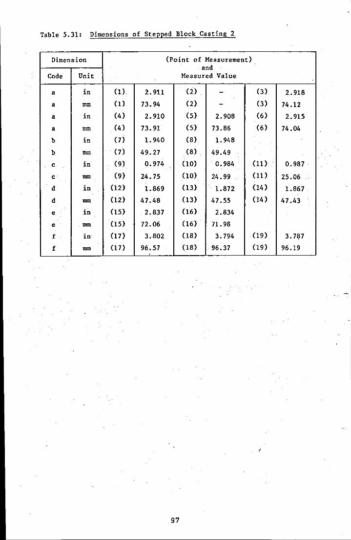
Table 5.31: Dimensions of Stepped Block Casting 2
Dimension (Point of Measurement) and
Code Unit Measured Value
a in (1) 2.911 (2) - (3) 2.918
a mm (1) 73.94 (2) - (3) 74.12
a in (4) 2.910 (5) 2.908 (6) 2.915
a mm (4 ) 73.91 (5) 73.86 (6) 74.04
b in (7) 1. 940 (8) 1.948
b mm (7) 49.27 (8) 49.49 ..
.
c in (9) 0.974 (10) 0.984 (ll) 0.987 .
c mm (9) 24.75 (10) 24.99 (ll) 25.06
d in (12) 1.869 (13) I 1.872 (14) 1.867 .
d mm (12) 47.48 (13) 47.55 (14) 47.43
e in (15) . 2.837 (16) 2.834
e mm (15) 72.06 (16) 71.98
f in (17) 3.802 (18) 3.794 (19) 3.787
f mm (17) 96.57 (18) 96.37 (19) 96.19
I
97
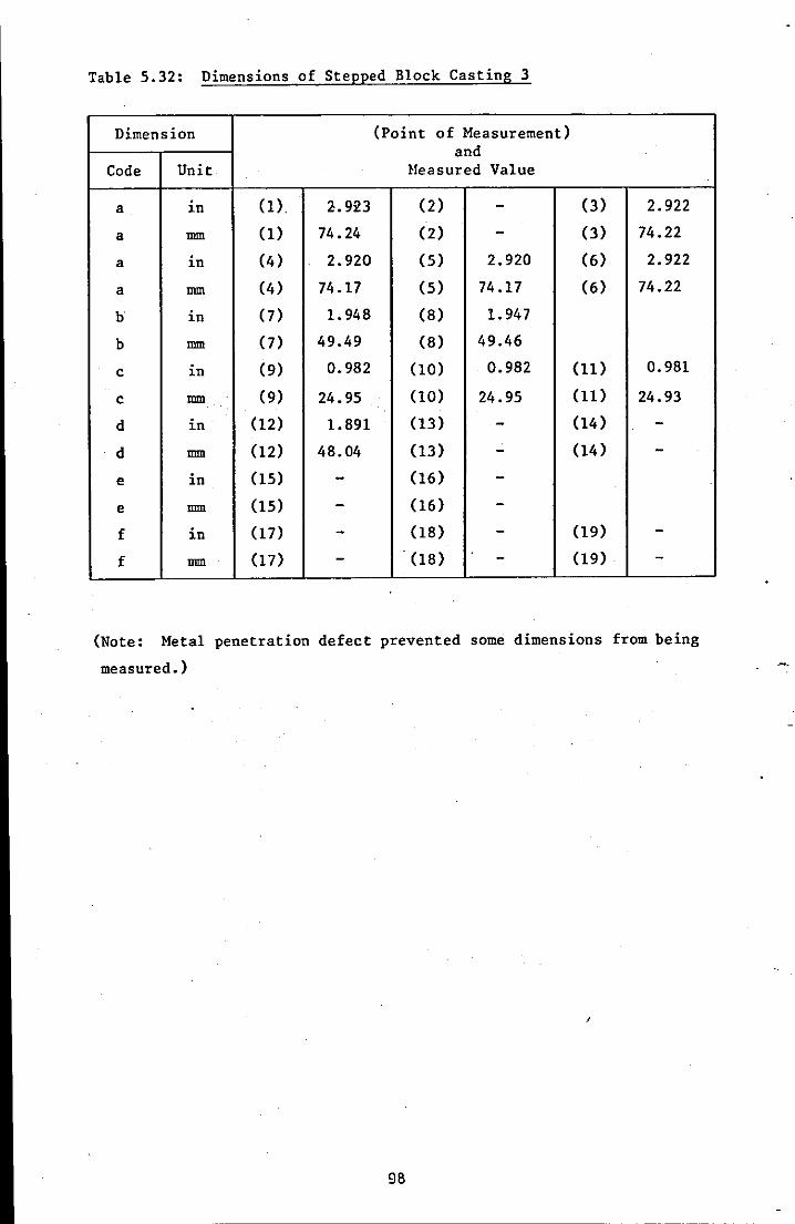
Table 5.32: Dimensions of Stepped Block Casting 3
Dimension (Point of Measurement) and
Code Unit Heasured Value
a in (1) 2.923 (2) - (3) 2.922
a mm (1) 74.24 (2) - (3) 74.22
a in (4) 2.920 (5) 2.920 (6) 2.922
a mm (4) 74.17 (5) 74.17 (6) 74.22
b in (7) 1.948 (8) 1.947
b mm (7) 49.49 (8) 49.46
c in (9) 0.982 (10) 0.982 (11) 0.981
c mm (9) 24.95 (10) 24.95 (11) 24.93
d in (12) 1.891 (13) - (14) -d mm (12) 48.04 (13) - (14) -e in (15) - (16) -e mm (15) - (16) -f in (17) - (18) - (19) -f mm (17) - (18) - (19) -
(Note: Metal penetration defect prevented some dimensions from being
measured.)
98

Table 5.33: Dimensions of Stepped Block Casting 13
Dimension (Point of Measurement) and
Code Unit Measured Value
a in (1) 2.883 (2) - (3) 2.886
a mm (1) 73.23 (2) - (3) 73.30
a . in (4 ) 2.878 (5) 2.897 (6) 2.902
a mm (4 ) 73.10 (5) 73.58 (6) 73.71
b in (7) 1.927 (8) 1.930
b mm (7) 48.95 (8) 49.02
c in (9) 0.970 (10) 0.977 (11) 0.970
c mm (9) 24.64 (10) 24.82 (11) 24.64
d in (12) 1.870 (13) 1.876 (14) 1.874
d mm (12) 47.50 (13) 47.65 (14) 47.60
e in (15) 2.833 (16) 2.835
e mm (15) 71.96 (16) 72.01
f in (17) 3.803 (18) 3.801 (19) 3.791
f mm (17) 96.60 (18) 96.55 (19) 96.29 .
/
99
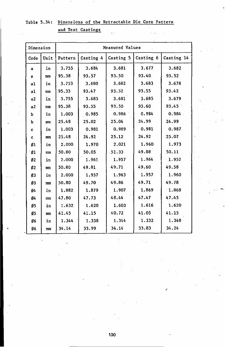
Table 5.34: Dimensions of the Retractable Die Core Pattern
and Test Castings
Dimension Measured Values
Code Unit Pattern Casting 4 Casting 5 Casting 6 Casting
a in 3.755 3.684 3.681 3.677 3.682
a mm 95.38 93.57 93.50 93.40 93.52
a1 in 3.753 3.680 3.682 3.683 3.678
a1 mm 95.33 93.47 93.52 93.55 93.42
a2 in 3.755 3.683 3.681 3.685 3.679
a2 mm 95.38 93.55 93.50 93.60 93.45
b in 1.003 0.985 0.986 0.984 0; 984 .
b mm 25.48 25.02 25.04 24.99 24.99
c in 1.003 0.981 0.989 0.981 0.987
c mm 25;48 24.92 25.12 24.92 25.07
01 in 2.000 1.970 2.021 1.960 1.973
01 mm 50.80 50.05 .51.33 49.88 50.11
02 in 2.000 1.961 1.957 1.964 1.952
02 mm 50.80 49.81 49.71 49.60 49.58
03 in 2.000 1.957 1.963 1.957 1.960
03 mm 50.80 49.70 49.86 49.71 49.78
04 in 1.882 1.879 1.907 1.869 1.868
04 mm 47.80 47.73 48.44 47.47 47.45 .
05 in 1.632 1.620 1.603 1.616 1.620 .
05 mm 41.45 41.15 40.72 41.05 41.15
06 in 1.344 1.338 1.344 1.332 1.348
06 mm 34.14 33.99 34.14 33.83 34.24
I
100
14
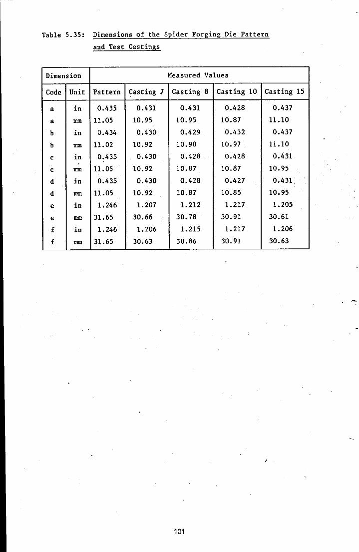
Table 5.35: Dimensions of the Spider Forging Die Pattern
and Test Castings
Dimension Measured Values
Code Unit Pattern Casting ] Casting 8 Casting 10 Casting
a in 0.435 0.431 0.431 0.428 0.437
a mm 11.05 10.95 10.95 10.87 11.10
b in 0.434 0.430 0.429 0.432 0.437
b mm 11.02 10.92 10.90 10.97 11.10
c in 0.435 0.430 0.428 0.428 0.431
c mm 11.05 10.92 10.87 10.87 10.95
d in 0.435 0.430 0.428 0.427 0.431.
d mm 11.05 10.92 10.87 10.85 10.95
e in 1.246 1.207 1.212 1.217 1.205
e mm 31.65 30.66 30.78 30.91 30.61
f in 1.246 1.206 1.215 1.217 1.206
f mm 31.65 30.63 30.86 30.91 30.63
I
101
15
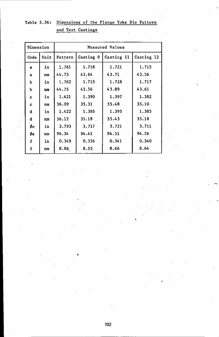
Table 5.36: Dimensions of the Flange Yoke Die Pattern
and Test Castings
Dimension Measured Values
Code Unit Pattern casting ') Casting 11 Casting 12
a in 1.761 1.718 1. 721 1. 715
a mm 44.73 43.64 43.71 43.56
b in 1.762 1.715 1. 728 1.717
b mm 44.75 43.56 43.89 43.61
c in 1.421 1.390 1.397 1.382
c mm 36.09 35.31 35.48 35.10
d in 1.422 1.385 1.395 1.385 .
d mm 36.12 35.18 35.43 35:18
!/le in 3.793 3.717 3.721 3.711
!/le mm 96.34 94.41 94.51 94.26
f in 0.349 0.336 0.341 0.340
f mm 8.86 8.53 8.66 8.64
102
I
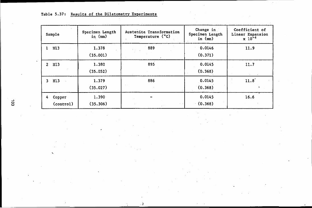
~
o w
Table 5.37: Results of the Dilatometry Experiments
Specimen Length Austenite Transformation Sample in (mm) Temperature (OC)
1 H13 1.378 889
(35.001)
2 H13 1.380 895
(35.052)
3 H13 1.379 886
(35.027)
4 Copper 1.390 -(control) (35.306) .
,
Change in Coefficient of Specimen Length Linear Expansion
in (mm) x 10-6
0.0146 11.9
(0.371)
0.0145 11.7
(0.368)
0.0145 11.8·
(0.368) •
0.0145 16.6
(0.368)

5.5 FINISHING PROCEDURES
5.5.1 Heat Treatment
The results of the bulk hardness tests conducted on the castings before
and after heat treatment ar~ sQown in Table 5.38.
The dimensions of the test castings after heat treatment are shown in
Tables 5.39 to 5.42 for the stepped block castings and Table 5.34 for
the retractable die core castings.
5.5.2 Electrical Discharge Machining
Electrical Discharge Machining was conducted using a Wickman EDM 0
machine with a 30 series power generator. A pure copper electrode was
used and a standard cutting voltage between 30 and 80 volts (open
circuit 90 volts) was selected according to the manufacturer's
recommendations. Details of the significance of machining parameters
are included in Chapter Three. Generally, a 'low frequency and:high
current produce the fastest cutting speed and the roughest finish on the
workpiece - with lowest electrode wear. As frequency is increased,
metal removal rate decreases, but the finish produced is finer.
Finishing passes should be undertaken at low amperage to produce a good
surface finish. The cutting conditions employed in these experiments
were:
Roughing: frequency 16 kHz
current 30 A
capacitance 15 I'F
Finishing: frequency 65 kHz
current 15 A
capacitance 2 I'F
Microhardness Measurements:
Microhardness measurements were conducted in the subsurface zone and
central section of "the A samples removed from each of the three stepped I •
blocks selected and the average microhardness values are presented in
Table 5.44. Microhardness measurements were also conducted on the
samples which had their as-cast surface removed by EDM. These
measurements were taken from the sub~machined surface zone and are
presented in Table 5.45.
104

Microstructures:
The microstructures of the as-cast surface and centre of the A sample
removed from test casting 13 were examined and compared with the micro
structures of the surfaces machined by EDM. Selected photomicrographs
are presented in Figures 5.88 to 5.95.
5.5.3 Electron Probe Microanalysis (EPMA)
The microanalysis was conducted using a Cambridge Microscan 5 instrument.
The samples for analysis were prepared using standard metallographic
techniques and mounted in conducting Bakelite. The samples were divided
into two groups, with the first group consisting of the A samples on
which the analysis would be conducted from the as-cast surface into the
bulk of the sample. Examination of these results would be 'expected to
show whether there was any difference attributable to the mould material I
mould atmosphere combination employed in the production of the casting.
The second group of samples consisted of those on which analysis would
be conducted from the surface machined by EDM into the bulk of the
casting. In the light of the results obtained from the first group of
samples, the second group consisted only of samples from test casting
13. These were: sample l3C; l3B; and l3D which had, respectively:
250 ~; 1.25 mm; and 2.85 mm of material removed from the as-cast
surface.
The elements of interest were the six principal elements present in the
Hl3 'die steel, namely: carbon; silicon; manganese; chromium; molybdenum
and vanadium. In addition, because a copper electrode was used during
EDM, an analysis for copper was also conducted on selected samples. As
it was only possible to conduct an analysis for two elements
simultaneously the following pairings were used: carbon and vanadium;
silicon and chromium; manganese and molybdenum; and copper and iron. A
lithium fluoride crystal was used in the analysis of chromium, copper,
manganese and vanadium; a mica crystal for iron, molybdenum and silicon;
and mica-stearate for carbon. A 'cold finger' was used to condense out
oil vapour in an attempt to eliminate error in the carbon readings. I
A continuous scanning mode was used, progressing across the Bakelite/
specimen interface and continuing for a nominal distance of 250 ~m from
the specimen surface. Whilst an attempt was made to conduct the paired
105

analyses on the same area, precise superposition of the beam could not
be guaranteed. The nominal beam diamter was 1 ~m, beam voltage 29 kV
and beam current between 1 and 2 x 10- 8 A. The instrument operated at
100 counts/second and the output was recorded on a chart recorder
operating at a chart speed of 10 mm/minute, with 1 mm on the chart
corresponding to 1 ~m on the specimen. Background levels for each
element were monitored and recorded after each scan. Duplicate scans
were conducted on several but not all specimens.
Presentation of EPMA Results:
The actual 'chemical analysis for each test casting was not known,
although the melting stock analyses were provided (see Appendix Five).
From the melting stock analyses a notional average melt analysis was
established:
Element
carbon
silicon
manganese
chr.omium
molybdenum
vanadium
%
0.43
1.55
0.54
4.78
1.52
1.15
For each specimen and for each of the six principal elements considered,
the following procedure was adopted. The element concentration,
recorded on the original chart, was measured at steps of 10 ~ (10 mm
'on the chart). From this measurement was deducted the mean element
background concentration. This was repeated for the measurements from
10 ~ to 250 ~ from the interface. The mean of these corrected.
measurements was calculated and equated to the notional melt analysis
value for that element. From this information a graph of % element
concentration vs distance from the interface could be drawn. Whilst
this approach does not provide a quantitative measure, it does permit
trends to be observed and enabled the results for a single specimen to
be observed simultaneously.
to 5.101.
The graphs are presented in Figures 5.96
/
The results for the analysis of copper, conducted on specimens l3A, l3C
and 130, could not be presented in the same way because an analysis for
106

copper in the melting stock was not available. For these specimens a
tracing of the actual chart recording is presented in Figures 5.102 to
5.104 respectively.
/
107
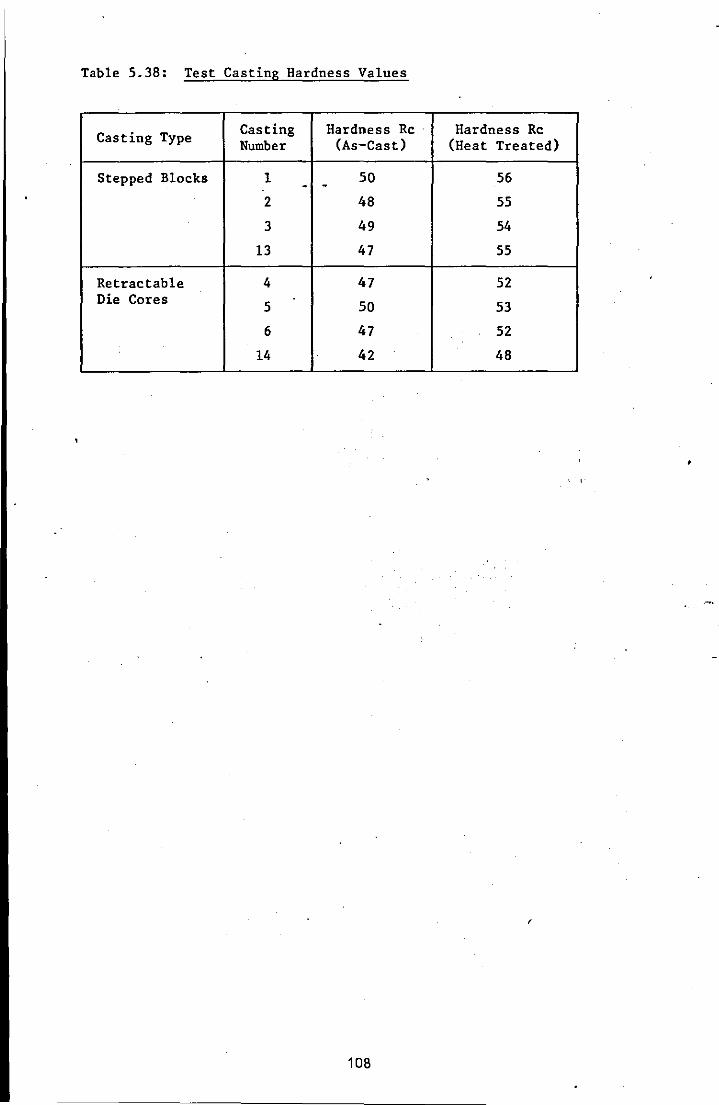
Table 5.38: Test Casting Hardness Values
Casting Type Casting Hardness Rc . Hardness Rc Number (As-Cast) (Heat Treated)
Stepped Blocks 1 50 56 - -2 48 55
3 49 54
13 47 55
Retractable 4 47 52 Die Cores 5 50 53
6 47 52
14 42 48
,
106
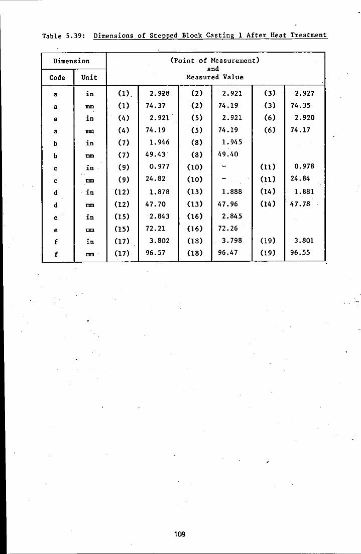
Table 5.39: Dimensions of Stepped Block Casting 1 After Heat Treatment
Dimension (Point of Measurement) and
Code Unit Measured Value
a in (1)- 2.928 (2) 2.921 (3) 2.927
a mm (1) 74.37 (2) 74.19 (3) 74.35
a in (4) 2.921 (S) 2.921 (6) 2.920
a mm (4) 74.19 (S) 74.19 (6) 74.17
b in (7) 1. 946 (8) 1.945
b mm (7) 49.43 (8) 49.40
c in (9) 0.977 (10) - (11) 0.978
c mm (9) 24.82 (10) - (11) 24.84
d in (12) 1.878 (13) 1.888 (14) 1.881
d mm (12) 47.70 (13) 47.96 (14) 47.78
e in (15) ·2.843 (16) 2.845
e mm (15) 72.21 (16) 72.26
f in (17) 3.802 (18) 3.798 (19) 3.801
f mm (17) 96.57 (18) 96.47 (19) 96.55
109
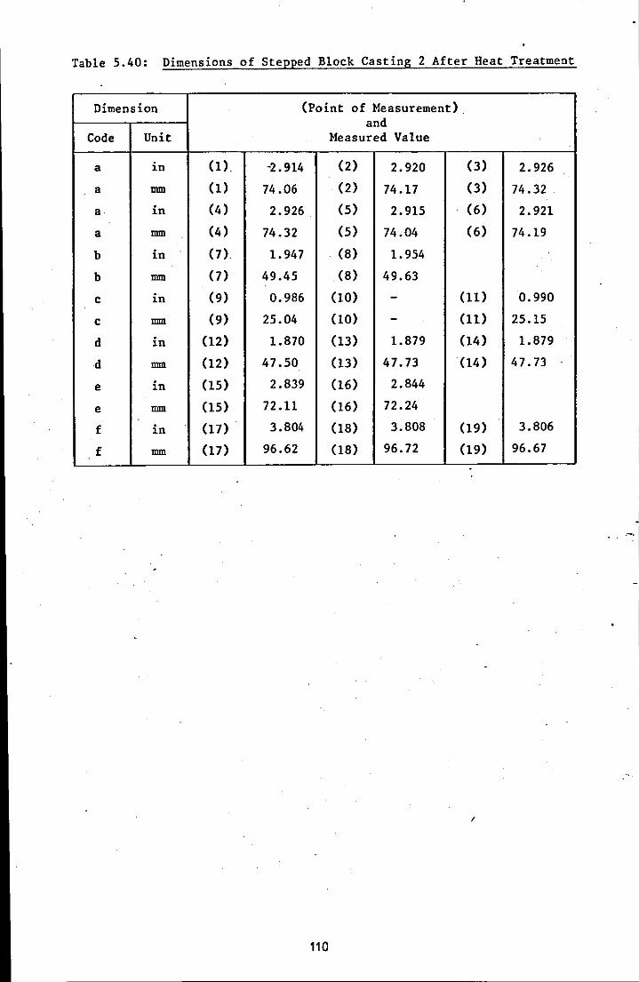
Table 5.40: Dimensions of Stepped Block Casting 2 After Heat Treatment
Dimension (Point of Measurement) . and
Code Unit Measured Value
a in (1). -2.914 (2) 2.920 (3) 2.926
a mm (1) 74.06 (2) 74.17 (3) 74.32
a· in (4) 2.926 (S) 2.915 (6) 2.921
a mm (4) 74.32 (5) 74.04 (6) 74.19
b in (7) 1.947 (8) 1.954
b mm 0) 49.45 (8) 49.63
c in (9) 0.986 (10) - (11) 0.990
c mm (9) 25.04 (10) - (11) 25.15
d in (12) 1.870 (13) 1.879 (14) 1.879
d mm (12) 47.50 (13) 47.73 (14) 47.73
e in (15) 2.839 (16) 2.844
e mm (15) 72.11 (16) 72.24
f in (17) 3.804 (18) 3.808 (19) 3.806
f mm (17) 96.62 (18) 96.72 (19) 96.67
/
110

Table 5.41: Dimensions of Stepped Block Casting 3 After Heat Treatment
Dimension (Point of Measurement) and
Code Unit Measured Value
a in (1) . 2-.928 (2) 2.927 (3) 2.930
a mm (1) 74.37 (2) 74.35 (3) 74.42
a in (4) 2.932 (5) 2.927 (6) 2.927
a mm (4) 74.47 (S) 74.35 (6) 74.35
b in (7) 1.952 (8) 1.951
b mm (7) 49.58 (8) 49.56
c in (9) 0.983 (10) 0.985 (11) 0.984
c mm (9) 24.97 (10) 25.02 (11) 24.99
d in (12) - (13) - . (14) -d mm (12) - (13) - (14) -e in (15) - (l6) -e mm (15) - (16) -f in (17) - (18) - (19) -f mm (17) - (18) - (19) -
.
/
111
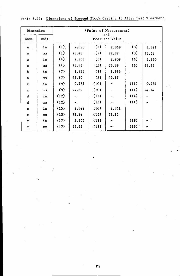
Table 5.42: Dimensions of Stepped Block Casting 13 After Heat Treatment
Dimension (Point of Measurement) and
Code Unit Measured Value
a in (1). 2.893 (2) 2.869 (3) 2.897
a mm (1) 73.48 (2) 72.87 (3) 73.58
a in (4) 2.908 (5) 2.909 (6) 2.910
a mm (4) 73.86 (5) 73.89 (6) 73.91
b in (7) 1.933 (8) 1.936
b mm (7) 49.10 (8) 49.17
c in (9) 0.972 (10) - (11) 0.974
c mm (9) 24.69 (10) - (11) 24.74
d in (12) - (13) - (14) -d mm (12) - (13) - (14) -e in (15) 2.844 (16) 2.841
e mm (15) 72.24 (16) 72.16
f in (17) 3.805 (18) - (19) -f mm (17) 96.65 (18) - (19) . -
112
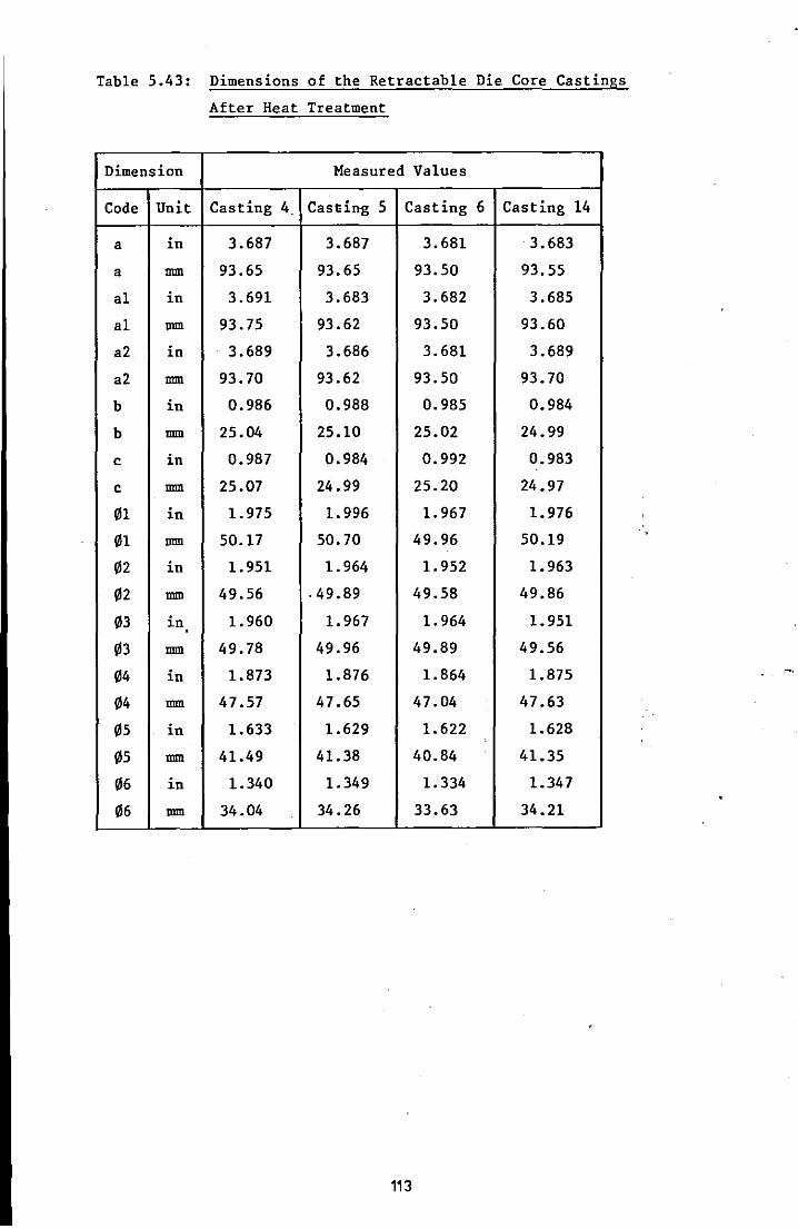
Table 5.43: Dimensions of the Retractable Die Core Castings
After Heat Treatment
Dimension Measured Values
Code Unit Casting 4. Casdng 5 Casting 6 Casting 14
a in 3.687 3.687 3.681 3.683
a mm 93.65 93.65 93.50 93.55
a1 in 3.691 3.683 3.682 3.685
a1 mm 93.75 93.62 93.50 93.60
a2 in 3.689 3.686 3.681 3.689
a2 mm 93.70 93.62 93.50 93.70
b in 0.986 0.988 0.985 0.984
b mm 25.04 25.10 25.02 24.99
c in 0.987 0.984 0.992 0.983
c mm 25.07 24.99 25.20 24.97
01 in 1.975 1.996 1.967 1.976
01 mm 50.17 50.70 49.96 50.19
02 in 1.951 1.964 1.952 1.963
02 mm 49.56 .49.89 49.58 49.86
03 in 1.960 1.967 1.964 1.951
03 mm 49.78 49.96 49.89 49.56
04 in 1.873 1.876 1.864 1.875
04 mm 47.57 47.65 47.04 . 47.63
05 in 1.633 1.629 1.622 1.628
05 mm 41.49 41.38 40.84 41.35
06 in 1.340 1.349 1.334 1.347
06 mm 34.04 34.26 33.63 34.21
113

Table 5.44: Average Vickers Microhardness Readings for Test Castings
Test Casting and Average Vickers Microhardness Values
Sample Number Casting Centre Casting Subsurface
lA 658- 607
2A 689 651
13A 621 630
Table 5.45: Average Vickers Microhardness Readings for the
Machined (EDM) Subsurface Zone of the Test Castings
Test Casting and Amount of Cast Surface Average Vickers Sample Number Removed by EDM (mm) Microhardness Values
1D 2.85 644
2B 1.25 711
2C 0.25 677
2D 2.85 653
13B 1.25 569
13C 0.25 584
13D 2.85 592
114
CHAPTER SIX
OBSERVATIONS AND DISCUSSION
6.1 INTRODUCTION
The results reported in Chapter 5 are discussed by section as follows:
6.2 Mould Material Evaluation
6.3 Metallurgical Processing
6.4 Test Castings Evaluation
6.5 Finishing Procedure
Whilst each section represents a distinct phase of activity and
experiments, and therefore justifies a separate discussion section,
the whole programme is inter-related. In an attempt to show how this
inter-relationship affects the quality of the· castings produced a
discussion summary, section 6.6, is also included.
In each section observations precede the detailed discussion of the
results.
115
6.2 MOULD MATERIAL EVALUATION
Obsepvations:
6.2.1 Backing Material
As indicated previously, a suitable supply of graded chamotte could not
be obtained. The material supplied provided extremely poor strength,
even when bonded with 6% by weight of sodium silicate. Figure 5.2 2 shows the as-gassed strength to be only around 350 kN/m , although on
standing for 24 hours the strength increased to around 1000 kN/m2, see
Figure 5.3. It was decided, therefore, to use molochite as a backing
material for the purposes of the investigation, although it was
recognised that a cheaper backing material would be preferable for
commercial applications.
The backing material was based on a 3:1:1 ratio blend of -8 + 16
-30 + 80 : -120 mesh grades of molochite. The effect of gassing time
and flow rate on the compression strength development of the molochite
blend bonded with 6% by weight sodium silicate is shown in Figure 5.4.
It can be seen that the as-gassed strengths of the molochite blend are
about five times higher than those for the chamotte material. From the
information presented in Figure 5.4, a gassing time of 2 minutes and a
flow rate of 5 litres/minute were chosen as a compromise to minimise
gas consumption whilst providing acceptable as-gassed strength. These
conditions were adopted for the production of all standard AFS
specimens. Under these conditions, specimens could be expected to 2 develop a compression strength of around 3500 kN/m after standing for
24 hours, as shown in Figure 5.5. This value was considered to be more
than adequate for the requirements of the backing material.
Because of the need to fire the moulds, the influence of firing
temperature and time at firing temperature on the backing material was
of interest. The tests conducted can be considered in two groups: (a)
tests carried out on the material at room temperature after it had been
heated to a higher temperature; and (b) tests carried out on the
material whilst it was at a high temperature. /
The retained strength of the backing material after heating to
temperature and cooling down to room temperature was established in
compression, see Figure 5.6, and tension, see Figure 5.7. In both
116

cases the graphs follow a similar pattern, strength increases with an
increase in firing temperature to a maximum at the nominal firing
temperature of 9000 C and then falls. In both cases the graphs for the
specimens held at firing temperatu~ for two hours show the highest
strengths.
Two other tests were conducted on specimens held at firing temperature
for two hours, namely change in specimen length and change in
permeability. Table 5.11 and Figure 5.8 show that the specimen length
decreased with an increase in firing temperature, and Table 5.12 shows
that the permeability increased as a result of heating to a high
temperature.
The high temperature tests on the backing material were restricted by
experimental difficulties to gas evolution and unimpeded linear
expansion. In the case of gas evolution, the tests indicated that the
material fired at either 750°C or 10000 C did not evolve any gas at the
proscribed testing temperature of 850°C, Table 5.13. The results for
unimpeded linear expansion, Figure 5.9, show a clear difference between
the material fired at 7500 C and that fired at 1000oC. Although, in
both cases, expansion increases with time to a maximum and then
decreases, the effect occurs more quickly in the material fired at
750°C and the maximum expansion figure is lower.
6.2.2 Facing Material
The effect of firing temperature and time at firing temperature on the
retained compression and tensile strength of the ceramic facing
material is shown in Figures 5.10 and 5.11 respectively. In both cases
the trend is similar, with strength increasing with an increase in
firing temperature to a maximum at the nominal firing temperature of o 1000 C. The results for specimens held at firing temperature for one
hour and three hours are very similar, whilst those for specimens held
at firing temperature for two hours are much lower. However, this does
not demonstrate the significance of firing temperature but an
inconsistency in binder quality, as the two hour specimens were
prepared from a different batch of prehydrolysed ethyl silicate.
The change in specimen length, measured for those specimens held at
firing temperature for two hours, was positive although small for each
firing temperature, see Table 5.17 and Figure 5.8. The permeability
117
values for the ceramic facing material were extremely low and no
significant change occurred as the result of firing the material, see
Table 5.18.
A full range of high temperature tests was conducted on the ceramic
facing material. The gas evnlution tests showed the material, whether
fired at 7500 C or 1000oC, to be inert, see Table 5.19. The results of
the hot distortion tests for specimens which had been fired at 7500 C
and 10000 C were similar, see Figures 5.12 and 5.13 respectively. In
all cases there was an expansion within the first 30 seconds, the value'
of which decreased with time during the remainder of the 10 minute
test. Discernible differences do exist between the material fired at
the different temperatures. In the case of the material fired at
750oC, the average maximum expansion was about 0.45 mm declining to
0.25 mm after 10 minutes. Whereas, for the material fired at 1000oC,
the average maximum expansion was 0.50 mm declining to 0.35 mm after 10
minutes.
The results for unimpeded linear expansion also follow a similar
pattern, see Figure 5.14, with expansion rising to a peak and then
declining. However, there is a clear difference between the results.
In the case of the material fired at 1000oC, the peak is higher and
occurs later than for the material fired at 750oC. Furthermore, the
peak value does not decline as markedly in the material fired at
1000oC.
It was possible to establish hot strength values for the ceramic facing
material and the'se are shown in Table 5.21. These results show that
the hot strength of the material fired at 10000 C was on average about
25% higher than for the material fired at 750oC.
6.2.3 Backing/Facing Material Interface
The strength of the interface bond was assessed by producing AFS
tensile specimens consisting of 50% backing material and 50% facing
material. The effect of firing temperature and time at firing
temperature is shown in Figure 5.15. The graphs show a small but
definite increase in strength with an increase in firing temperature up o to the maximum nominal firing temperature of 1000 C. The specimens
held at firing temperature for two hours show the lowest strength for
the reason outlined previously. It was observed that the tensile
118

specimens did not always break at the interface. A significant number
broke within the ceramic facing material~ but none broke in the sodium
silicate bonded backing material.
Discussion:
The effect of heat on the retained strength of silicate bonded sand was
explained by Nicholas (98), as follows:
It is characteristic for the retained strengths of silicate bonded o 0 sands to have two maxima, one at approximately 200 -300 C and a
second at about 9000 C. The highest strength is generally developed . 0
at about 900 C.
The strength changes at temperatures up to approximately 5000 -6000 C
are due to dehydration of ungassed sodium silicate followed by
softening of the bond. At higher temperatures the retained
strengths increase again due to chemical reaction between residual
sodium silicate and sodium compounds with grains of quartz sand. In
this manner a continuous monolithic structure of high strength is
formed as the temperature is raised from 600o-900oC. At higher
temperatures the quartz form of silica transforms to tridymite
and/or crystobalite. This transformation is accompanied by a large
volume increase, which can be as high as 30-40%, and the stresses
.produced lower the retained strength.
In the case of the sodium silicate bonded molochite used in this
investigation, the graph of retained compression strength shown in
Figure 5.6 shows a similar trend over the nominal firing. temperature o 0 range of 500 -1000 C. However, the composition of molochite is
different to the silica sand considered by Nicholas. Molochite is an
alumino-silicate refractory containing approximately 52% silica and 42%
alumina (99). Whilst there is no reason to expect a difference between
the two materials' properties up to around 9000 C, the fall-off in
strength associated with the sodium silicate bonded molochite fired to o 1000 Cis less easy to explain. Measurements of the change in specimen
length do not show the large volume increase associated with the
transformation of B quartz in the silica system. As this change is
considered to be the cause of the reduction in strength in the silica
sands, its absence in the molochite should not be associated with the
observed decline in strength.
119
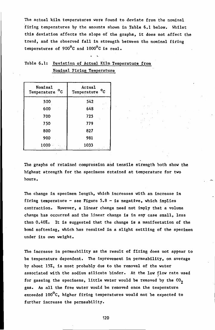
The actual kiln temperatures were found to deviate from the nominal
firing temperatures by the amounts shown in Table 6.1 below. Whilst
this deviation affects the slope of the graphs, it does not affect the
trend, and the observed fall in strength between the nominal firing
temperatures of 900°C and 10000 C is real.
Table 6.1: Deviation of Actual Kiln Temperature from
Nominal Firing Temperature
Nominal Actual Temperature °c Temperature °c
500 542
600 648
700 725
750 779
800 827
900 981
1000 1033 .. .
The graphs of retained compression and tensile strength both show the
highest strength for the specimens retained at temperature for two
hours.
The change in specimen length, which increases with an increase in
firing temperature - see Figure 5.8 - is negative, which implies
contraction. However, a linear change need not imply that a volume
change has occurred and the linear change is in any case small, less
than 0.40%. It is suggested that the change is a manifestation of the
bond softening, which has resulted in a slight settling of the specimen
under its own weight.
The increase in permeability as the result of firing does not appear to
be temperature dependent. The improvement in permeability, on average
by about 15%, is most probably due to the removal of the water
associated with the sodium silicate binder. At the low flow rate used I
for gassing the specimens, little water would be removed by the CO2 gas. As all the free water would be removed once the temperature
o exceeded 100 C, higher firing temperatures would not be expected to
further increase the permeability.
120

The experiments to establish gas evolution showed the material to be
inert. If the only volatile ingredient in the backing material was the
water associated with the sodium silicate, this result would be
expected. Under these circumstances the choice of firing temperature,
that is 7500C or 1000oC, would not exert any influence.
The results of the experiments to establish unimpeded linear expansion,
Figure 5.9, appear to confirm that there is a softening of the silicate
bond at higher temperatures. At the start of each test the specimen
was loaded in slight compression to ensure positive contact between the
silica discs and rods. The shape of the graphs clearly indicates that
softening of the bond occurs, which would account for the contraction
phase which follows the initial expansion. Because the material fired
at 10000C has a higher retained strength than that fired to 750oC, the
effect of bond softening is delayed.
During early mould firing trials it was noticed that unsupported
corners of the backing mould cracked and in some cases broke away.
This effect was clearly much worse at the higher firing temperatures.
It was determined, empirically, ~hat a nominal firing temperature of
7500 C should not be exceeded to maintain the integrity of the backing
mould. The effect suggested that collapse occurred due to a softening
of the bond at higher temperatures and this appears to be confirmed by
the change in specimen length results and those for unimpeded linear
expansion.
o In selecting 750 C as the nominal firing temperature for the moulds it
was necessary to establish the differences, if any, between the mould
material fired to 7500C or 1000oC. As the preceding results indicate,
there was no significant reason why this choice should not be made.
In the case of the ceramic facing material, the retained strengths
after firing are much lower than those obtained for the sodium silicate
bonded material. The retained st~engths increase progressively up to
the maximum nominal firing temperature of 1000oC, which tends to
suggest that the reduction in strength of the backing material may be
related to the presence of sodium oxide (100). One reason for the
lower strength of the facing material is the particle size gradings
used. The facing material contains 50% of the fine grade (-100 mesh)
mulLite ' and the associated large surface area increases the binder
121
demand to achieve high strength. Although the results show that a high
firing temperature is necessary to develop the highest strength, the
rate of strength development is not high. Hence, it can be seen from
the graph in Figure 5.10 that if the moulds were fired at 7500 C instead
of 10000 C, they would still develop about 90% of the strength obtained
at 10000 C. Very high strength'in the facing material might not be
desirable, as it could present hot tearing or distortion problems
associated with poor breakdown.
Measurements of the change in specimen length for the facing material
suggest it to be quite stable. The very slight expansion recorded for
all specimens was, on average, less than 0.1%. The permeability of the
facing material containing such a high proportion of fine material was
very low. The before firing tests Were conducted. on samples which had
been 'torched' and would therefore show any benefit obtained through
'micro-crazing'. Even though the material is essentially inert, the
low permeability could be a problem in resisting the displacement of
air or inert gas from the mould cavity by the incoming metal. However,
in the test casting moulds the facing layer would not exceed 13 mm, and
this layer would be more permeable than the 50.8 mm thickness·
associated with the AFS sample.
The inertness of the material was confirmed by the gas evolution tests.
No gas was evolved, at 8500 C, from the material previously fired to
either 7500 C or 10000 C •.
The results of the hot distortion tests were strongly indicative of the
stability of the facing material and showed, as expected, that heat has
little effect on breakdown.
Similarities exist between the unimpeded linear expansion results for
the backing and facing materials. However, the ceramic facing material
resists the effect of bond softening for a longer period. The material
fired to 10000 C resists softening significantly better than that fired
to 7500 C. From the graphs it appears that the facing material has a
higher coefficient of linear expansion. However, the di~ference may be
due to the better resistance to softening exhibited by the facing
material. The hot strength results for the facing material show the
material fired at 10000 C to be, on average, 25% stronger than that
fired to 7500 C. A comparison between the retained compression
122
strengths after firing and cooling shows the difference to be around
101.. The greater difference in hot strength may reflect the improved
resistance to softening exhibited by the material fired to 1000oC.
The strength of the bond between the backing and facing material is
very low. For a firing temperature of 7500 C the retained tensile
strength of the composite test piece, by extrapolation, would be about 2 80 kN/m , which is around half that expected from the ceramic material
and just over 101. of that expected from the sodium silicate bonded
material. However, a bond does exist, which suggests that some of the
ethyl silicate present in the ceramic slurry penetrates the backing
material at the interface during mould production.
From the results obtained,
firing temperature for the
it was considered that an acceptable nominal o test casting moulds would be 750 C and that
a holding time of two hours at the maxi~um temperature would be
sufficient. These conditions were a compromise between minimising the
damage to the backing material and maximising the strength of the
facing material. Whilst the experiments showed that facing material
fired to 10000 C had better cold strength and hot strength
characteristics, the difference was not considered significant for the
production of successful castings.
/
123
6.3 METALLURGICAL PROCESSING
Obsel"Vations:
6.3.1 Macroexamination
Visual examination of the ingot'castings enabled certain observations
to be made from which important conclusions could be drawn. Although
brief details are included in Table 5.23, further observations on each
series of experiments are made below.
Series I to III (Figures 5.16 to 5.18):
All nine castings in this group exhibit the pitting defect. However,
the severity appears to increase with both an increase in the pouring
temperature (furn~ce temperature) and an increase in the mould preheat
temperature. Castings produced in the moulds preheated to the highest
temperature (800oC) appear to show an increased number of pits which
are smaller in size than those on the castings produced in cooler
moulds.
Series IV (Figures 5.19 i and 5.19 ii):
Tbe use of a nitrogen atmosphere has almost completely suppressed the
pitting defect. In addition, the nitrogen atmosphere has suppressed
the formation of oxide scale, Figure 5.19 ii.
Series V (Figure 5.20):
Increasing the addition level of the deoxidiser, Stellagen 1, appears
to decrease the severity of the pitting defect.
Series VI (Figure 5.21):
Increasing the addition level of the grain refining agents had no
demonstrable effect On the severity of the pitting defect.
Series VII and VIII (Figures 5.22 and 5.23):
Tbe castings produced in air (Series VII) exhibit the pitting defect. "
However, the severity of the defect appears to have been reduced by the
addition of the deoxidiser to the melt. Tbe pitting defect has been
suppressed in those castings produced in a nitrogen atmosphere (Series
VIII), although the surface quality cannot be described as good. Tbere
is evidence of a penetration-like defect.
124
Series IX to XI (Figures 5.24 to 5.26):
The presence of 10 weight % graphite in the mould facing material has
suppressed the formation of the pitting defect. The castings produced
from moulds preheated to BOOoe have an inferior surface quality with
evidence of a penetration-like defect.
Series XII (Figure 5.27):
The presence of graphite in the mould facing material has suppressed
the pitting defect. However, the surface quality of the castings is
not good and is similar to the equivalent castings in Series VII and
VIII (Figures 5.22 and 5.23).
Series XIII and XIV (Figures 5.28 and 5.29):
The combination of a mould material containing graphite and the
presence of an inert gas atmosphere during casting and solidification
did not produce castings of improved quality. Whilst the pitting
defect was suppressed in all cases, the ingot castings produced with
the nitrogen atmosphere exhibited poor surface quality. The ingot cast
at 16000 e had a matte effect finish, whilst that cast at 17000e had
severe penetration-like defects. Although the ingots produced at lower
casting temperatures in an argon atmosphere possessed reasonable o surface quality, that cast at 1700 e exhibited severe penetration-like
defects.
Series XV (Figures 5.30):
The castings produced using a zircon mould facing material exhibited
the pitting defect.
Series XVI (Figures'5.31):
The castings produced in the machined graphite mould had a very poor
surface quality as a result of the presence of gross gas defects.
Series XVII (Figures 5.32):
These castings exhibited the pitting defect; indicsting that the , addition of up to 3 weight % nickel to the melt is ineffective for
eliminating the defect.
125
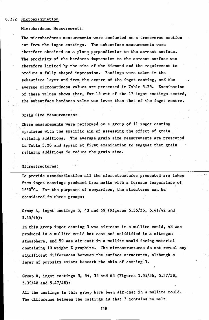
6.3.2 Microexamination
Microhardness Measurements:
The microhardness measurements were conducted on a transverse section
cut from the ingot castings. The subsurface measurements were
therefore obtained on a plan~ p~rpendicular to the as-cast surface.
The proximity of the hardness impression to the as-cast surface was
therefore limited by the size of the diamond and the requirement to
produce a fully shaped impression. Readings were taken in the
subsurface layer and from the centre of the ingot casting, and the
average microhardness values are presented .in Table 5.25. Examination
of these values shows that,. for 15 out of the 17 ingot castings tested,
the subsurface hardness value was lower than that of the ingot centre.
Grain Size Measurements:
These measurements were performed on a group of 11 ingot casting
specimens with the specific aim of assessing the effect of grain
refining additions. The average grain size measurements are presented
in Table 5.26 and appear at first examination to suggest that grain
refining additions do reduce the grain size.
Microstructures:
To provide standardisation all the microstructures presented are taken
from ingot castings produced from melts with a furnace temperature of
16500 C. For the purposes of comparison, the structures can be
considered. in three groups:
Group A, ingot castings 3, 43 and 59 (Figures 5.35/36, 5.41/42 and
5.45/46):
In this group ingot casting 3 was air-cast in a mullite mould, 43 was
produced in a mullite mould but cast and solidified in a nitrogen
atmosphere, and 59 was air-cast in a mullite mould facing material
c·ontaining 10 weight % graphite. The microstructures do not reveal any
significant differences between the surface structures, although a
layer of porosity exists beneath the skin of casting 3. ,
Group B, ingot castings 3, 34, 35 and 63 (Figures 5.35/36, 5.37/38,
5.39/40 and 5.47/48):
All the castings in this group have been air-cast in a mullite mould.
The difference between the castings is that 3 contains no melt
126

---------------_ .. _--
additions, 34 has been deoxidised, 35 has been grain refined, and 63
has been deoxidised and grain refined. The microstructures do not
reveal any significant difference between the surface structures.
Group C, ingot castings 63, 58 and 59 (Figures 5.47/48, 5.43/54 and
5.45/46):
All the castings in this group have been deoxidised and gr~in refined •.
Casting 63 was air-cast in a mullite mould, 58 was moulded in mullite
but cast and solidified in a nitrogen atmosphere, and 59 was air-cast
but moulded in mullite containing 10 weight % graphite. The
microstructures do not reveal any significant difference between the
surface structures.
Figure 5.49 a and b show two magnifications of the centre structure of
ingot casting 37. The structure is typical of the whole group of ingot
castings.
DiS~U88ion: ,
The ingot castings produced in mullite moulds and cast in air exhibited
the pitting defect. The severity of the defect increased with both
mould preheat temerature and pouring temperature. The presence of
surface pitting was expected and has been observed by other researchers
(21, 59, 60). If the pitting defect is the result of a metal/mould
reaction which occurs at high temperatures (21) then it would be
expected that the slower rate of cooling, produced by higher pouring
temperature and/or mould temperature, would exacerbate the problem.
Reducing the effect of oxygen either by casting with an inert gas
atmosphere or incorporating graphite in the mould facing material
suppressed the formation of the pitting defect. These results conform
with the findings and suggestions in the literature (59, 62). The
ingot castings produced using a nitrogen atmosphere were almost scale
free, unlike those produced in the moulds containing graphite and cast
in air. This has a practical implication in that scale~free castings
may not require shotblasting and may therefore possess improved surface
finish and dimensional accuracy.
For the series of castings produced from deoxidised melts, both the
mould and metal temperatures were maintained at a constant level. The
127
addition of deoxidiser to the melt reduced but did not eliminate the
extent of the pitting defect. Although this effect was not described
in the literature, the addition of certain deoxidisers to the mould
material (57) has been recommended to reduce or prevent surface
decarburisation. The presence of an element which oxidises
preferentially to carbon should'curtail the mechanism by which the
pitting defect occurs (60).
The addition of grain refining additions to the melt had no discernable
effect on the extent of the surface pitting defect. In the castings
produced from melts which had been treated with both deoxidiser and
grain refiners there was evidence that the pitting defect had been
reduced. Melts ,treated with the combined additions, were poured at
different'temperatures, but the mould temperature ,remained a constant.
Perhaps the most disappointing results were those for the ingot
castings produced in moulds containing graphite and cast in either a
nitrogen or argon atmosphere. Whilst it would be reasonable to expect
that this combination might provide the best possible surface quality,
in practice this was not the case. Whils~ the pitting defect was
absent, other surface defects were present. Although the castings
produced at the two lower temperatures using an argon atmosphere had a
better surface quality than those produced with a nitrogen atmosphere,
they were certainly no better than those cast in air. The very poor
surface finish with penetration-like defects, found on the ingots cast
at 17000 C in both argon and nitrogen, might be due to the combination
of high pouring temperature and the absence of an oxide skin promoting
the conditions for metal penetration.
The experiments using machined graphite moulds were performed to
evaluate the possibility of using a semi-permanent mould process, as
well as to confirm the suitability of graphite as a pitting defect
suppressor. Whilst the results were poor, it should be noted that
neither a mould coating nor quiescent method of mould filling were
used. These features are present in the Griffin process used
successfully to produce cast steel wheels for railway requirements. ,
Zircon moulds have been recommended as suitable for casting die steels
(18), but in these experiments the pitting defect was observed on the
ingot castings, a feature confirmed by other workers (61). The
128

addition of nickel to the melt has been suggested as a method of
suppressing the pitting defect (18, 61). However, in these experiments
the addition of up to 3 weight % nickel was not found to be effective
in this respect.
From observations made as a result of the ingot casting programme, the
following recommendations are suggested as a means of minimising the
extent of the surface pitting defect and maximising the surface quality
of castings:
1 Moulds produced in mullite should be cast and solidified in an inert
gas atmosphere or, alternatively, be produced with an addition of 10
weight % graphite if they are to be cast in air.
2 Moulds should not be preheated, unless the presence of thin sections
dictates this to ensure mould filling.
3 The metal pouring temperature should be kept as low as possible.
4 The molten metal should be treated with a suitable deoxidiser.
As indicated previously, the, subsurface microhardness was lower than
that of the centre in 15 of the 17 ingot castings tested. The mean
average microhardness value for the casting subsurfaces was 625, with a
range of 550 to 733, and that for the casting centres was 686, with a
range of 636 to 763. A simple statistical test (101) suggested that
the difference in microhardness values between the subsurface and
centre of the ingots was significant. Applying a more discriminating
method (102), based on determining the standard error of the mean,
confirmed that the differences in microhardness were statistically
significant. Details of the statistical tests are presented in
Appendix Seven.
The subsurface microhardness readings were all taken within a zone
extending 0.1 mm from the surface of the ingots. It was considered
that this zone would be representative of the 'casting skin'. The
reduced microhardness levels in this suface zone might be· due to a
lower level of carbon resulting from decarburisation. A lower casting
skin hardness was observed by other researchers using a slightly
different approach to establish hardness and using a very different
steel (103).
To assess the effect of grain refining additions, a statistical
comparison was performed on selected ingot castings from the group of
eleven detailed in Table 5.26. Castings 3 and 43, to which no
additions were made, were considered as one sample (A) and castings 62,
63 and 66, to which had been added a deoxidiser and grain refining
additions, as a second sample (B). The statistical tests are detailed
in Appendix Seven, where the values used to calculate the average
number of grains intercepted, shown in Table 5.26, are shown in full
for the ingot castings under consideration. The mean value of sample A
was 3.7, with a range of 2.7 to 4.7, and that for sample B was 5.4,
with a range of 4.3 to 6.0. A simple statistical test (104) suggested
a significant difference and this was confirmed by the more
discriminating test. (102).
Whilst the addition of grain refining additions clearly decreases grain
size, no mechanical tests were performed on the cast H13 die steel and
so a quantitative, assessment of the benefit of grain refinement was not
obtained. However, a correlation could exist· between hardness ~alues
and grain size. An analysis was conducted for association (105) using
the data from Tables 5.25 and 5.26 and is shown in Appendix Seven.
However, the analysis did not show any significant association.
The microstructures presented in Figures 5.35 to 5.48 are essentially
similar and show the typical features of cast H13 die steel (l06). The
structures consist of some carbide particles in a matrix of unt,empered
martensite (dark areas) and retained austenite (light areas). Some
porosity and non-metallic inclusions are present in most specimens. No
visually distinguishable surface layer could be detected in the
microstructures. The roughness of the surface was apparent, especially
at high magnifications. The rough surface exists on ingot castings
produced in a mullite mould and cast in either air or nitrogen and on
the castings produced in a mullite mould facing containing graphite.
In some cases, surface depressions lead directly into grain boundaries
where there is evidence of oxidation (see Figure 5.48). These features
could provide initiation points for crack propagation in service if the
cast surface was not removed by a ·finishing operation.
Neither the microhardness readings nor the microstructures provided
evidence to suggest that the casting skin possessed qualities which
merit retention. The evidence suggests the opposite, with the
microhardness of the subsurface layer being generally lower than that
130

of the casting centre and the microstructures revealing at best an
undulating surface; but generally one containing pits and
protruberances. Whilst this rough surface layer is generally quite
shallow; below 35 ~m; its removal would improve the integrity of the
surface.
/
131
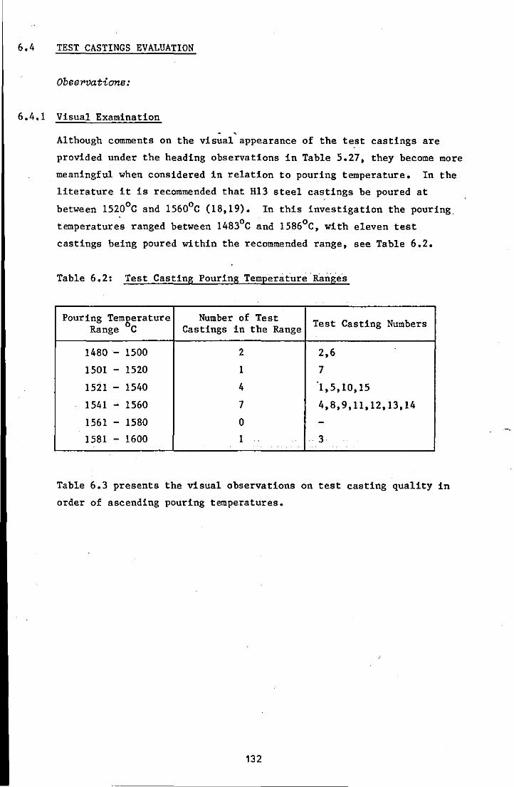
6.4 TEST CASTINGS EVALUATION
Obse1'vations:
6.4.1 Visual Examination - ,
Although comments on the visual appearance of the test castings are
provided under the heading observations in Table 5.27, they become more
meaningful when considered in relation to pouring temperature. In the
literature it is recommended that H13 steel castings be poured at
between 15200 C and 15600 C (18,19). In this investigation the pouring, , 0 0
temperatures ranged between 1483 C and 1586 C, with eleven test
castings being poured within the recommended range, see Table 6.2.
Table 6.2: Test Casting Pouring Temperature RaTiges
Pouring Temgerature Number of Test Test Casting Numbers Range C Castings in the Range
1480- 1500 2 2,6
1501 - 1520 1 7
1521 - 1540 4 1,5,10,15
1541 - 1560 7 4,8,9,11,12,13,14
1561 - 1580 0 -1581 - 1600 1 3
.
Table 6.3 presents the visual observations on test casting quality in
order of ascending pouring temperatures.
132

Table 6.3: Observations on Test Castings Related to
Pouring Temperature
Pouring Temperature ·C
1483
1500
1516
1523
1530
1540
1540
1545
1545
1550
1550
1550
1555
1555
1586
Test Casting Number
2
6
7
1
5
10
15
9
12
8
11
14
4
13
3
Observations
Cold laps and rounded edges present.
Cold laps and rounded edges present, especially in the teeth.
Some cold laps present on the cavity edge.
Rounded edges with poor definition.
Poor Aefinition in the teeth, some pitting evident.
Some evidence of cold laps with some poor edge definition.
No evidence of cold laps, poor surface quality in the cavity, some 'evidence of penetration.
No evidence of cold laps.
No evidence of cold laps, good edge definition.
Not perfect but generally good definition, evidence of slight penetration.
Cold laps due to overspill down the open head, quite severe pitting defect evident.
No evidence of cold laps, imperfect teeth form but better than 5 and 6, some pitting evident.
Not perfect but much better edge definition than 5 and 6.
No cold laps, good edge definition but penetration defects present.
No cold laps, good edge definition, penetration defects worse than 13.
133
6.4.2 Dimensions and Surface Finish
Whilst the details for casting and pattern dimensions and surface
finish are presented in section 5.4, the values by themselves provide
little information. In order to establish the influence of such
variables as: casting weight; mould material; mould atmosphere and
pouring temperature on the accuracy and quality of surface finish of
,:, the castings, the data must be suitably processed.
Dimensions The dimensions of each test casting were compared with the
equivalent pattern dimensions and the % deviation, of the casting
dimension from the pattern dimension, established:
let a = pattern dimension - casting dimension
then, % deviation = a 'x 100 pattern dimension
Under normal circumstances it would be expected that the % deviation
would be negative because the casting contracts. The % deviation
values for each group of test castings are presented in Tables 6.4 to
6.7.
The % deviation values have been used in two ways. Firstly the average
% deviation value, compounded for the range'of each casting's
dimensions, was calculated for each test casting. With this
information, and considering the castings by type, it was hoped to
identify any relationship between average % deviation and the
variables: pouring temperature; casting weight; and mould material!
mould atmosphere. Secondly by grouping the average % deviations in
bands, according to the original pattern dimensions, it was hoped to
identify any relationship between average % deviation and the size of
the dimension.
Pouring Temperature:
No meaningful diagramatic representation could be found to express a
relationship between pouring temperature and average % deviation.
Casting Weight:
Figure 6.1 shows the average % deviation values plotted according to
the casting type or weight.
134
I
Mould Material/Mould Atmosphere:
Figure 6.2 shows the average % deviation values plotted against the
different mould material/mould atmosphere combinations.
Effect of Dimension Size:
ftFigure 6.3 shows the average % deviation values plotted against the
nominal pattern dimension for four distinct pattern dimension bands.
Surface Finish The mean Ra and Wa values for the test castings were
established from the individual readings conducted on each casting and
are presented in Table 6.8. Table 6.9 presents the equivalent values
for the patterns. In an attempt to identify any relationship with
process variables, the mean Ra and Wa values were treated as follows:
Pouring Temperature:
No meaningful diagramatic representation could be found to express a
relationship between pouring temperature and either Ra or Wa.
Casting Weight:
Figure 6.4 shows the mean Ra values for the test castings plotted
according to the casting type or weight. Figure 6.5 shows the
equivalent relationship for mean Wa values.
Mould Material/Mould Atmosphere:
Figure 6.6 shows the mean Ra values plotted against the different mould
material/mould atmosphere combinations and Figure 6.7 the equivalent
relationship for the mean Wa values.
Bearing Ratio The bearing ratio curves are shown in Figures 5.66 to
5.70; 5.72 to 5.76; 5.78 to 5.82; and 5.84 to 5.87. With only a few
exceptions, these graphs were very similar. The average values for
both patterns and castings are shown in Table 6.10.
6.4.3 Contraction Allowance
The determination of the contraction allowance required experiments to
determine the melting point (solidus temperature) of the H13 die steel
and its coefficient of linear expansion. The information obtained is
considered in the subsequent discussion and no specific observations
are presented.
135

DiseU8sion:
Assuming the liquidus temperature for H13 die steel to be about 14750 C
(97,107) it is not surprising that the two castings poured below 15010 C
are characterised by very poor surface quality, cold laps and poor edge
definition. Although these two castings exhibited the poorest surface - , quality, cold laps and poor edge definition were generally evident in
tho'~e castings poured at temperatures between 15010 C and 1540oC. It
was not until the pouring temperature exceeded 1541 0 C that cold laps
were no longer evident and good edge definition was obtained. However,.
even at the highest pouring temperatures, the teeth of the retractable
die core were not perfectly formed.
Some evidence of pitting was seen in test castings 5, 11 and 14. Test
castings 5 and 11 were poured and cooled under a nitrogen atmosphere
snd test casting 14 was produced in a mould containing 10 weight %
graphite in the facing material. According to the results obtained in
the production of ingot castings, these conditions should have produced
castings free from the pitting defect. An objective assessment of the
methods of processing the moulds during firing and prior to casting may
highlight limitations which have resulted in the appearance of the
pitting defect.
The moulds were fired in ,an electrically heated kiln with an air
(oxidising) atmosphere. If graphite is to be effective in suppressing.
the pitting defect it must remain in the facing material. Despite
attempts to prevent its loss during mould firing, by using covers,
there was evidence to suggest that some loss was occurring. A
difference in colour was observed, with the deeper pockets retaining s
darker grey colouration after firing than those areas near to the top
(joint) face of the moulds. Whilst this may explain the occurrence of
the pitting defect on the retractable die core casting 14, it should be
noted that several other castings were produced in the same mould
material and without the defect. Oxidising conditions are normally
recommended when firing Shaw process moulds (44) to ensure the removal
of any volatile material. However, on reflection, it would seem
appropriate to use either a reducing or inert atmosphere to prevent the
loss of graphite.
The use of a nitrogen atmosphere for test casting production was not as
successful as it was for ingot casting production. Whereas the ingot
136
castings showed no sign of the pitting defect and were almost free of
oxide· scale, two of the four test castings produced using a nitrogen
atmosphere exhibited the pitting defect and all four exhibited an oxide
scale which required a shotblasting treatment to remove it. In the
case of the ingot castings, small castings were produced in small open
top moulds in a small container'flushed with relatively high flow rates
of nitrogen. The castings cooled down to room temperature within a few
hours. In the case of the test castings, much larger castings were
produced in large, predominantly sealed, moulds in a large container
with a relatively low flow rate of nitrogen. These castings cooled
very slowly and were still too hot to handle when broken from the
moulds 24 hours later.
The observed metal penetration defect .takes the form of small, almost
spherical, protrusions on the surface of the test castings. The defect
appears to be formed by metal penetrating the mould skin to fill small
voids formed by air bubbles present during mould manufacture. The
defect is at its worst in the casting poured at the highest temperature
of 15860 C. Three of the four castings exhibiting the defect were
produced in moulds in which the mould facing contained. 10 weight %
graphite. It is possible that the increased volume of fine material
caused more air to be entrapped in the slurry. Altering.the pattern
vibration conditions during mould filling and/or careful control of the
metal pouring temperature may eliminate this problem.
The laps which spoil the cavity in test casting 11 were the result of
careless pouring, which allowed metal to spill over the bush side and
down the open head. The defect could have been prevented by covering
the open head with a refractory board.
The spider forging dies all exhibited a sink in the top (as-cast)
surface and in some cases a draw in the ingate. The calculated head
size should have been sufficient to feed the casting and trial castings
were produced without apparent shrinkage defects. It is possible that
the neck connecting the feeder head to the casting may not have been
sufficiently large. ,
The retractable die core castings all showed imperfections in the teeth
form to some extent. The casting is fairly small, cast weight 1.6 kg,
and the heat loss during filling with the associated loss of fluidity
would be quite high. The gating system design and low mould
137
-------------------- --_ ..
permeability may also be contributory factors to poor definition.
However, it is possible that the problems experienced may indicate a
limit to the shape complexity possible without preheating the mould.
Dimensions:
An examination of Figures 6.1 t~ 6.3 does not reveal any apparent
relationships. In Figure 6.1 the castings are considered by type and
weight. The approximate cast weights are as follows:
retractable die core (rack core)
stepped block
spider forging die
flange yoke forging die
1.6 kg
2.9 kg
7.0 kg
IB.O kg
The group means for the % deviation from pattern dimension for each
type of casting range from -1.17 to -2.37, compared with the overall
average for all fifteen castings of -1.65. If the results for the
retractable die core were excluded, there would appear to be a trend
with % deviation increasing with casting weight.
When the % deviation values are grouped according to mould material/
atmosphere combinations, the group means range from -1.57 to -1.71 and
are therefore grouped very much more closely around the overall average
of -1.65, see Figure 6.2. This appears to suggest that the mould
material/atmosphere combination is not a significant process variable
-with regard to its influence on dimensional variations.
When the % deviation values are grouped according to the nominal
pattern dimensions, there is once more no clear trend. The group mean
values range from -1.29 to -1.94, which compares with the overall
average of -1.6B.
Surface Finish:
The equipment available for measuring surface finish has been developed
to accommodate the common conventional machined surfaces in engineering
which are produced by grinding, milling or turning (lOB). Machined /
surfaces have a definite, regular, repetitive, directional pattern and
defining a cross-section of the machined pattern defines the surface.
In contrast, cast surfaces have an irregular, random pattern and there
can be a wide latitude in the mathematical value within a small area
138

(109). For this reason conventional stylus measuring machines have
been considered inappropriate, especially where sand cast surfaces are
considered (110).
The inherently smoother surfaces associated with precision casting
permit stylus measuring machines to be used and, if the limitations are
accepted, they may still provide a useful method of comparison in the
absence of a suitable alternative. In these experiments the three
aspects of surface finish measured were:
Roughness Average
Waviness
Bearing Ratio
Ra
Wa
.tp
In the case of machined surfaces, roughness refers to the
irregularities in the production process left by the actual machining -
agent (eg cutting tool, grit, spark). Waviness may result from such
factors as machine or work deflections, vibrations, chatter, various
causes of strain in the material, and extraneous influences (111).
Whilst these feature do not apply directly to the production of a cast
surface, they are clearly involved in the production of the patterns
and may in part be translated to the casting finish. The roughness of
the casting surface will be affected by the grain size of the
refractory aggregate used in moulding. In these experiments a wide
_ range of particle sizes was used to formulate the facing mix and this
would be expected to exert an influence. As Ra and Wa essentially
measure surface roughness of different frequencies, it is possible that
the results could reflect the presence of fine refractory particles in
Ra and large refractory particles in Wa. This interpretation would
differ from the definition of waviness in the case of machined
surfaces, which defines waviness as that component of surface texture
upon which roughness is superimposed.
Mathematically, Ra is the arithmetic average value of the departure of
the profile from the centre line thoughout the sampling length. Ra
gives no information as to the shape of the irregularities or profile
and no distinction is made between peaks and valleys. Ra'must be
quoted in conjunction with the meter cut-off value, for which 0.8 mm is
the most universally recommended.
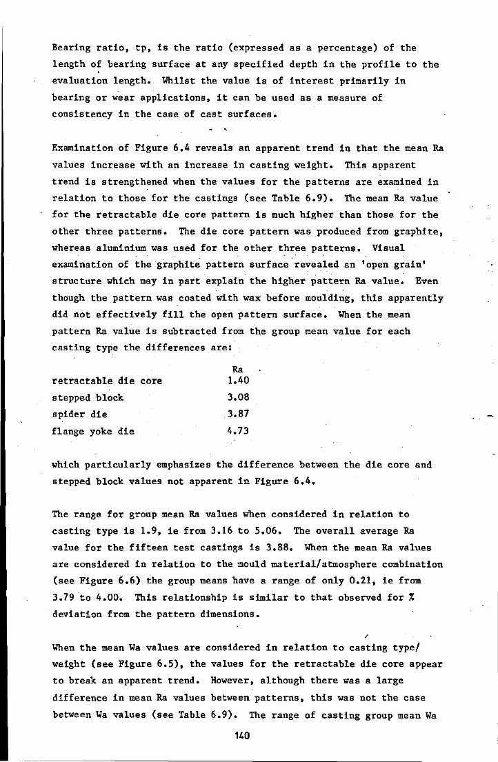
Bearing ratio, tp, is the ratio (expressed as a percentage) of the
length of bearing surface at any specified depth in the profile to the
evaluation length. Whilst the value is of interest primarily in
bearing or wear applications, it can be used as a measure of
consistency in the case of cast surfaces.
Examination of Figure 6.4 reveals an apparent trend in that the mean Ra
values increase with an increase in casting weight. This apparent
trend is strengthened when the values for the patterns are examined in
relation to those for the castings (see Table 6.9). The mean Ra value
for the retractable die core pattern is much higher than those for the
other three patterns. The die core pattern was produced from graphite,
whereas aluminium was used for the other three patterns. Visual
examination of the graphite pattern surface revealed an 'open grain'
structure which may in part explain the higher pattern Ra value. Even
though the pattern was coated with wax before moulding, this apparently
did not effectively fill the open pattern surface. When the mean
pattern Ra value is subtracted from the group mean value for each
casting type the differences are:
retractable die core
stepped block
spider die
flange yoke die
Ra 1.40
3.08
3.87
4.73
which particularly emphasizes the difference between the die core and
stepped block values not apparent in Figure 6.4.
The range for group mean Ra values when considered in relation to
casting type is 1.9, ie from 3.16 to 5.06. The overall average Ra
value for the fifteen test castings is 3.88. When the mean Ra values
are considered in relation to the mould material/atmosphere combination
(see Figure 6.6) the group means have a range of only 0.21, ie from
3.79 ·to 4.00. This relationship is similar to that observed for %
deviation from the pattern dimensions.
/
When the mean Wa values are considered in relation to casting type/
weight (see Figure 6.5), the values for the retractable die core appear
to break an apparent trend. However, although there was a large
difference in mean Ra values between patterns, this was not the case
between Wa values (see Table 6.9). The range of casting group mean Wa
140
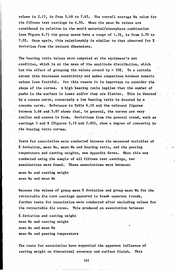
values is 2.17, ie from 5.48 to 7.65. The overall average Wa value for
the fifteen test castings is 6.50. When the mean Wa values are
considered in relation to the mould material/atmosphere combination
(see Figure 6.7) the group means have a range of 1.32, ie from 5.70 to
7.02. Once again, this relationship is similar to that observed for %
deviation from the pattern dimensions.
The bearing ratio values were computed at the equipment's set
condition, which is at the mean of the amplitude distribution, which
has the effect of grouping the values around tp = 50%. To a certain
extent this decreases sensitivity and makes comparison between numeric
values less fruitful. For this reason it is important to consider the
shape of the curves. A high bearing ratio implies that the number of
peaks in the surface is lower and/or they are flatter. This is denoted
by a convex curve, conversely a low bearing ratio is denoted by a
concave curve. Reference to Table 6.10 and the relevant figures
between 5.66 and 5.87 shows that, in general, the curves are very
similar and convex in form. Deviations from the general trend,. such as
castings 5 and 8 (Figures 5.73 and 5.80), show a degree of concavity in
the bearing ratio curves.
Tests for association were conducted between the measured variables of
% deviation, mean Ra, mean Wa and bearing ratio, and the pouring
temperature and casting weights, see Appendix Seven. When this was
conducted using the sample of all fifteen test castings, two
associations were found. These associations were between:
mean Ra and casting weight
mean Ra and mean Wa
Because the values of group mean % deviation and group mean Wa for the
retractable die core castings appeared to break apparent trends,
further tests for association were conducted after excluding values for
the retractable die cores. This produced an association between:
% deviation and casting weight
mean Ra and casting weight
mean Ra and mean Wa
mean Wa and pouring temperature
I
The tests for association have supported the apparent influence of
casting weight on dimensional accuracy and surface finish. This
141
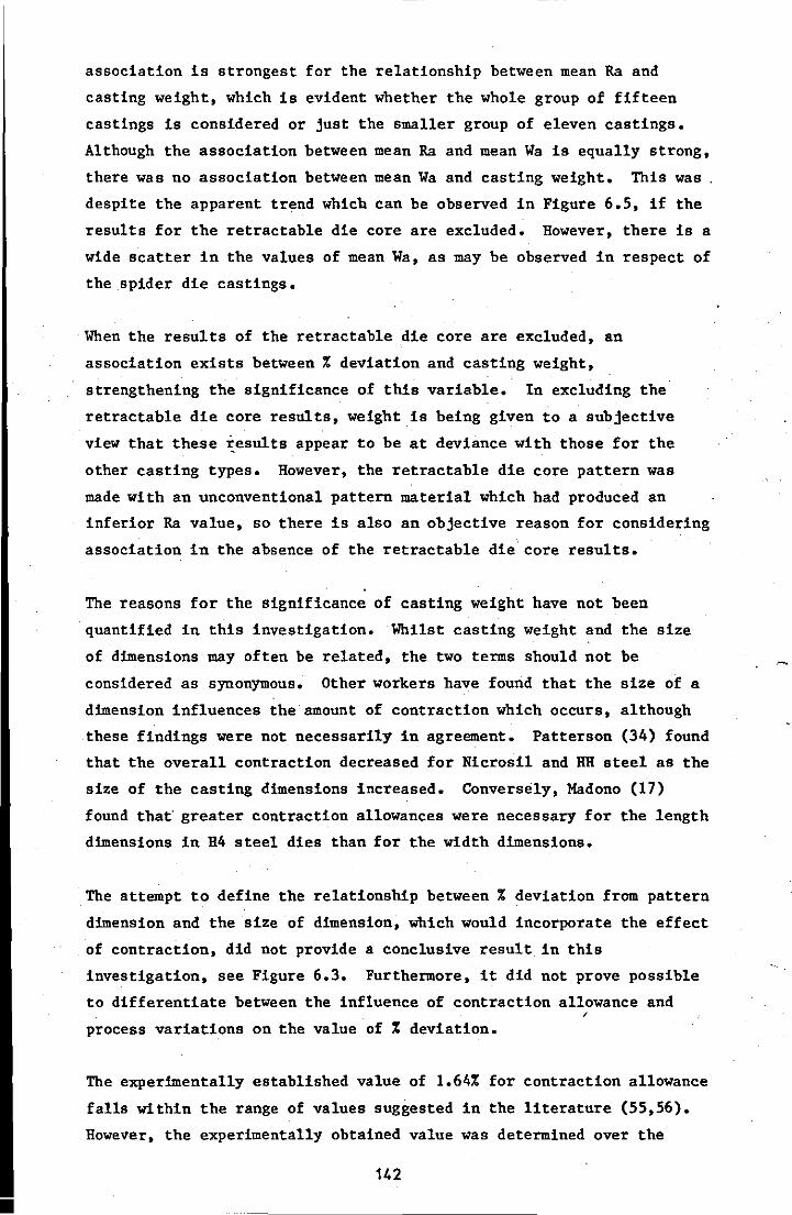
•
association is strongest for the relationship between mean Ra and
casting weight, which is evident whether the whole group of fifteen
castings is considered or just the smaller group of eleven castings.
Although the association between mean Ra and mean Wa is equally strong,
there was no association between mean Wa and casting weight. This was.
despite the apparent trend which can be observed in Figure 6.5, if the
results for the retractable die core are excluded. However, there is a
wide scatter in the values of mean Wa, as may be observed in respect of
the spider die castings.
When the results of the retractable die core are excluded, an
association exists between % deviation and casting weight,
strengthening the significance of this variable. In excluding the
retractable die core results, weight is being given to a subjective
view that these ~esults appear to be at deviance with those for the
other casting types. However, the retractable die core pattern was
made with an unconventional pattern material which had produced an
inferior Ra value, so there is also an objective reason for considering
association in the absence of the retractable die core results.
The reasons for the significance of casting weight have not been
quantified in this investigation. Whilst casting weight and the size
of dimensions may often be related, the two terms should not be
considered as synonymous. Other workers have found that the size of a
dimension influences the amount of contraction which occurs, although
these findings were not necessarily in agreement. Patterson (34) found
that the overall contraction decreased for Nicrosil and RH steel as the
size of the casting dimensions increased. Conversely, Madono (17)
found that greater contraction allowances were necessary for the length
dimensions in H4 steel dies than for the width dimensions.
The attempt to define the relationship between % deviation from pattern
dimension and the size of dimension, which would incorporate the effect
of contraction, did not provide a conclusive result in this
investigation, see Figure 6.3. Furthermore, it did not prove possible
to differentiate between the influence of contraction allowance and , process variations on the value of % deviation.
The experimentally established value of 1.64% for contraction allowance
falls within the range of values suggested in the literature (55,56).
However, the experimentally obtained value was determined over the
142
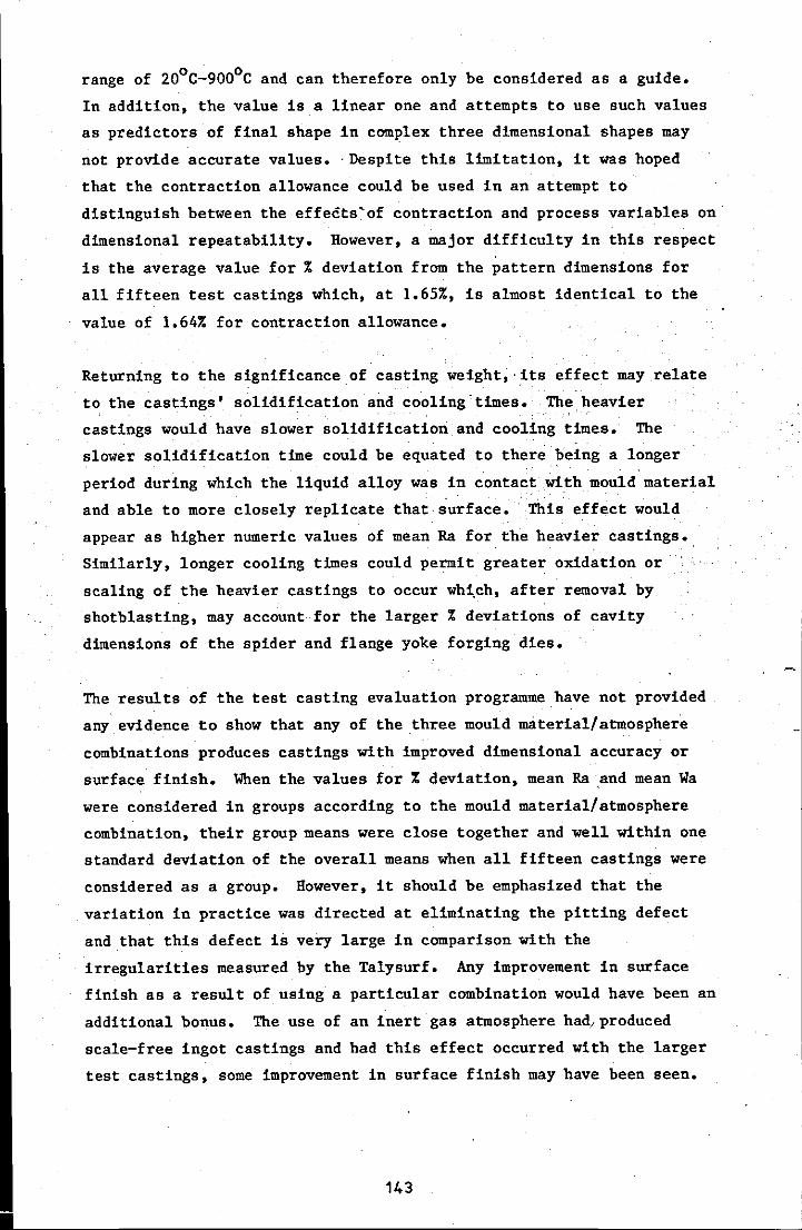
•
o 0 range of 20 C-900 C and can therefore only be considered as a guide.
In addition, the value is a linear one and attempts to use such values
as predictors of final shape in complex three dimensional shapes may
not provide accurate values. ,Despite this limitation, it was hoped
that the contraction allowance could be used in an attempt to
distinguish between the effects'of contraction and process variables on
dimensional repeatability. However, a major difficulty in this respect
is the average value for % deviation from the pattern dimensions for
all fifteen test castings which, at 1.65%, is almost identical to the
value of 1.64% for contraction allowance.
Returning to the significance of casting weight,'its effect may relate
to the castings' solidification and cooling times. The heavier
castings would have slower solidification and cooling times. The
slower solidification time could be equated to there being a longer
period during which the liquid alloy was in contact withmould'material
and able to more closely replicate that surface. This effect would
appear as higher numeric values of mean Ra for the heavier castings.,
Similarly, longer cooling times could permit greater oxidation or '
scaling of the heavier castings to occur wh~ch. after removal by
shotblasting, may account for the larger % deviations of cavity
dimensions of the spider and flange yoke forging dies.
The results of the test casting evaluation programme have not provided
any evidence to show that any of the three mould material/atmosphere
combinations produces castings with improved dimensional accuracy or
surface finish. When the values for % deviation, mean Ra ,and mean Wa
were considered in groups according to the mould material/atmosphere
combination, their group means were close together and well within one
standard deviation of the overall means when all fifteen castings were
considered as a group. However, it should be emphasized that the
variation in practice was directed at eliminating the pitting defect
and that this defect is very large in comparison with the
irregularities measured by the Talysurf. Any improvement in surface
finish as a result of using a particular combination would have been an
additional bonus. The use of an inert gas atmosphere had/produced
scale-free ingot castings and had this effect occurred with the larger
test castings, some improvement in surface finish may have been seen.
143

If the results of this investigation were used as a tolerance guide,
incorporating contraction allowance and process variations, the
following table could be produced:
For dimensions up to 26 mm ( IV 1 in) t 0.32 mm (t 0.013 in)
For dimensions between 26- 51 mm (N 1-2 in) t 0.70 mm (t 0.028 in) - , For dimensions between 51- 77 mm ('" 2-3 in) t 1.01 mm (t 0.040 in)
For dimensions between 77-102 mm ('" 3-4 in) t 1.70 mm (t 0.067 in)
The surface finish (Ra) values obtained ranged between 2.5 and 5.75)Lm, .
which compares with a claimed possible best value of 2.0},m for the
Shaw Process and the typical 5 to 10ym for sand moulded castings (25).
144
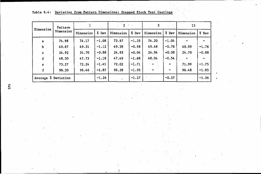
Table 6.4: Deviation from Pattern Dimensions: Stepped Block Test Castings
.
Pattern 1 2 3 13 Dimension Dimension Dimension % Dev Dimension % Dev Dimension .% Dev Dimension % Dev
a 74.98 74.17 -1.08 73.97 -1.35 74.20 -1.04 - -b 49.87 49.31 -1.12 49.38 -0.98 49.48 -0.78 48.99 -1.76
c 24.92 24.70 -0.88 24.93 +0.04 24.94 +0.08 24.70 -0.88
d 48.30 47.73 -1.18 47.49 -1.68 48.04 -0.54 - -e 73.27 72.24 -1.41 72.02 -i,n - - 71.99 -1. 75
f 98.30 96.46 -1.87 96.38 -1.95 - - 96.48 -1.85
Average % Deviation -1.26 -1.27 -0.57 -1.56

Table 6.5: Deviation from Pattern Dimensions: Retractable Die Core Test Castings
Pattern 4 5 6 . 14 Dimension Dimension Dimension % Dev Dimension % Dev Dimension % Dev Dimension % Dev
a 95.38 93.57 -1.90 93.50 i -1.97 93.40 -2.08 93.52 -1.95
a1 95.33 93.47 -1.95 93.52 -1.90 93.55 -1.87 93.42 -2.00
a2 95.38 93.55 -1.92 93.50 -1.97 93.60 -1.87 93.45 -2.02
b 25.48 25.02 -1.81 25.04 -1.73 24.99 -1.92 24.99 -1.92
c 25.48 24.92 -2.20 25.12 -1.41 24.92 -2.20 25.07 -1.61
01 50.80 50.05 -1.48 51.33 +1.04 49.88 -1.81 50.11 -1.36
02 50.80 49.81 -1.95 49.71 -2.15 49.60 . -2.36 49.58 -2.40
03 50.80 49.70 -2.17 49.86 -1.85 49.71 -2.15 49.78 -2.01
04 38.27 38.20 -0.18 38.91 +1.67 37.94 -0.86 37.92 -0.91
05 31.92 31.62 -0.94 31.19 -2.29 31.52 -1.25 31.62 -0.94
06 24.61 24.46 -0.61 24.61 0 24.30 -1.26 24.71 +0.41
Average % Deviation* -1.96 -1.80 -1.99 -1.90
* across the joint dimensions excluded
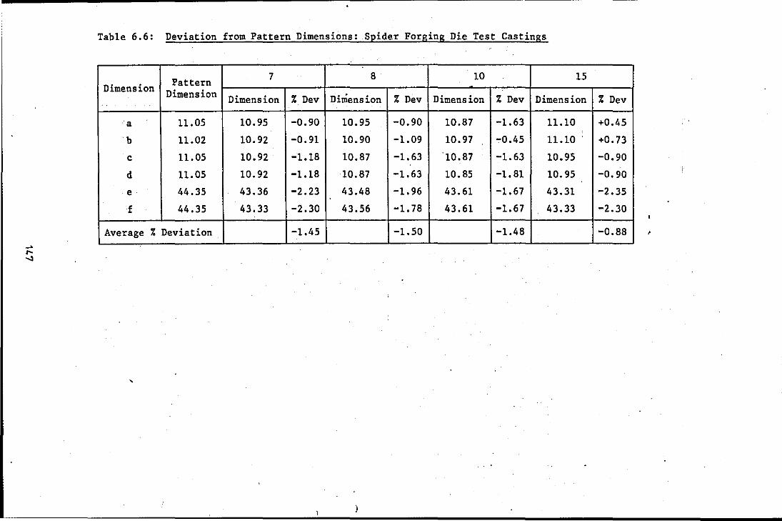
Table 6.6: Deviation from Pattern Dimensions: Spider Forging Die Test Castings
Pattern 7 8 10 15 Dimension Dimension Dimension % Dev Dimension % Dev Dimension % Dev Dimension % Dev
a 11.05 10.95 -0.90 10.95 -0.90 10.87 -1.63 11.10 +0.45
b 11.02 10.92 -0.91 10.90 -l.09 10.97 -0.45 11.10 +0.73
c 11.05 10.92 -1.18 10.87 -1.63 '10.87 -1.63 10.95 -0.90
d 11.05 10.92 -1.18 10.87 -1.63 10.85 -1.81 10.95 -0.90
e 44.35 43.36 -2.23 43.48 -1.96 43.61 -1.67 43.31 -2.35
f 44.35 43.33 -2.30 43.56 -1.78 43.61 -1.67 43.33 -2.30
Average % Deviation. -1.45 -1.50 -1.48 -0.88 ,
,
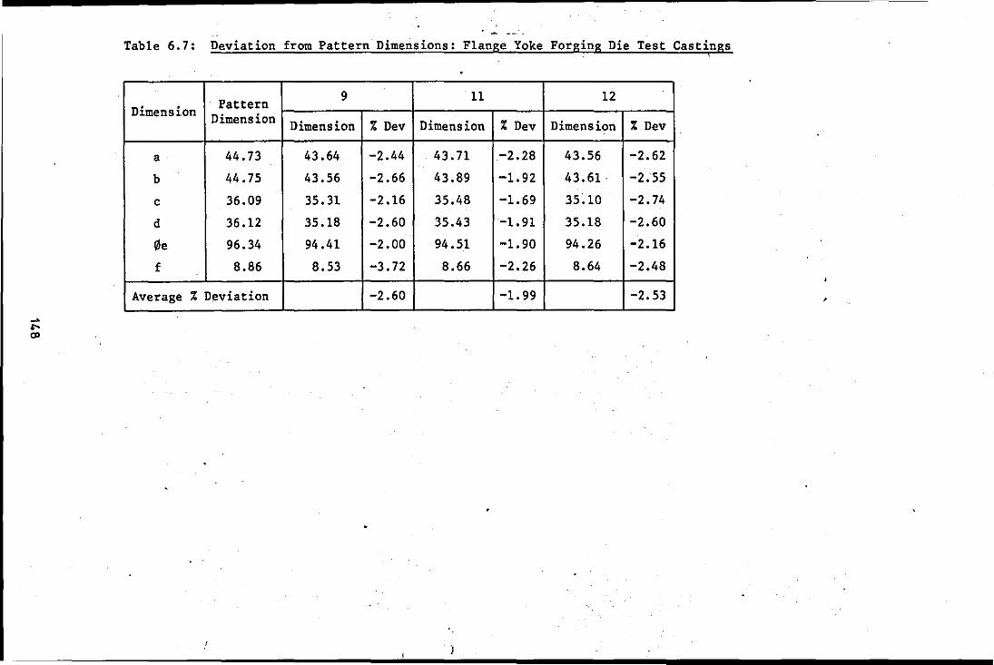
Table 6.7: Deviation from Pattern Dimensions: Flange Yoke Forging Die Test Castings ,
Pattern 9 11 12 Dimension Dimension Dimension % Dev Dimension % Dev Dimension % Dev
a 44.73 43.64 -2.44 43.71 -2.28 43.56 -2.62
b 44.75 43.56 -2.66 43.89 -1.92 43.61 . -2.55
c 36.09 35.31 -2.16 35.48 -1.69 35.10 -2.74
d 36.12 35.18 -2.60 35.43 -1.91 35.18 -2.60
0e 96.34 94.41 -2.00 94.51 -1.90 94.26 -2.16
f 8.86 8.53 -3.72 8.66 -2.26 8.64 -2.48
Average % Deviation -2.60 -1. 99 -2.53
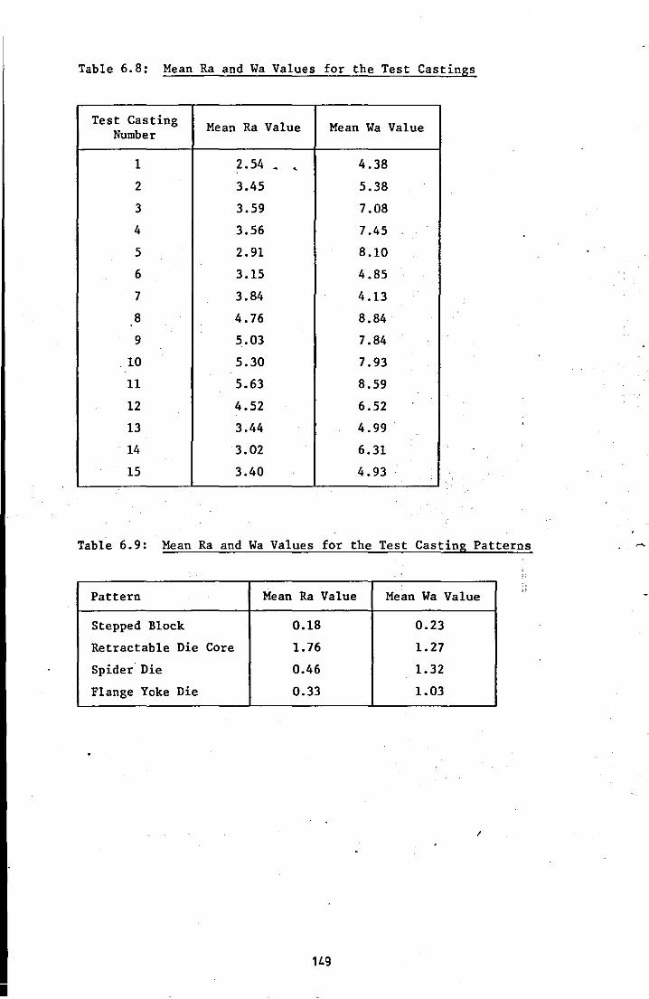
•
Table 6.8: Mean Ra and Wa Values for the Test Castings
Test Casting Mean Ra Value Mean Wa Value Number
1 2.54 _ , 4.38
2 3.45 5.38
3 3.59 7.08
4 3.56 7.45
5 2.91 8.10
6 3.15 4.85
7 3.84 4.13
8 4.76 8.84
9 5.03 7.84
.10 5.30 7.93
11 5.63 8.59
12 4.52 6.52
13 3.44 4.99
14 3.02 6.31
15 3.40 4.93
Table 6.9: Mean Ra and Wa Values for the Test Casting Patterns
.
Pattern
Stepped Block
Retractable Die Core
Spider Die
Flange Yoke Die
Mean Ra Value
0.18
1.76
0.46
0.33
1L9
Mean Wa Value
0.23
1.27
1.32
1.03
I
, j:

Table 6.10: Average Bearing Ratio Values for Test Castings
and Patterns
Description Bearing Ratio tp
(%) - ,
Patterns
Retractable Die Core 51.07
Stepped Block 50.95
Spider Forging Die 49.75
Flange Yoke Die 49.75
Average Value 50.38
Castings
1 47.97
2 50.80
3 49.40 -4 47.37
5 46:30
6 51.90
7 51.25
8 43.80
9 52.35
10 49.00
11 49.85
12 54.65
13 50.17
14 52.20
15 51. 75
Average Value 49.92
150
.------------------------------------------------------------------
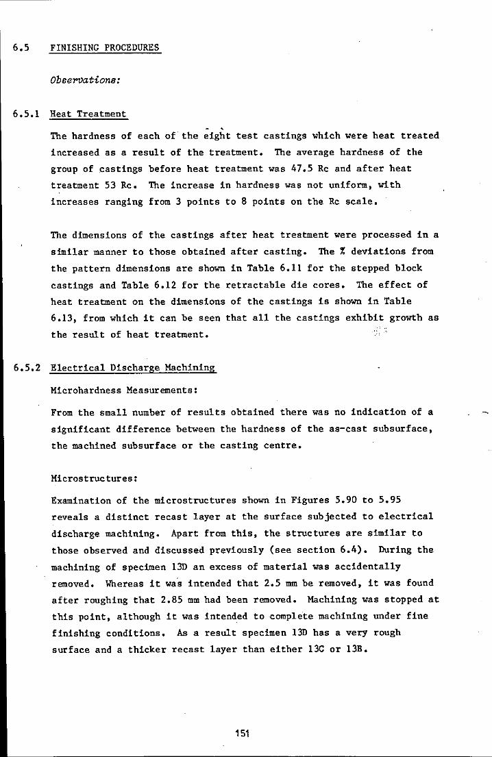
6.5 FINISHING PROCEDURES
Observations:
6.5.1 Heat Treatment
The hardness of each of the eight test castings which were heat treated
increased as a result of the treatment. The average hardness of the
group of castings before heat treatment was 47.5 Rc and after heat
treatment 53 Rc. The increase in hardness was not uniform, with
increases ranging from 3 points to 8 points on the Rc scale.
The dimensions of the castings after heat treatment were processed in a
similar manner to those obtained after casting. The % deviations from
the pattern dimensions are shown in Table 6.11 for the stepped block
castings and Table 6.12 for the retractable die cores. The effect of
heat treatment on the dimensions of the castings is shown in Table
6.13, from which it can be seen that all the castings exhibit growth as
the result of heat treatment.
6.5.2 Electrical Discharge Machining
Microhardness Measurements:
From the small number of results obtained there was no indication of a
significant difference between the hardness of the as-cast subsurface,
the machined subsurface or the casting centre.
Microstructures:
Examination of the microstructures shown in Figures 5.90 to 5.95
reveals a distinct recast layer at the surface subjected to electrical
discharge machining. Apart from this, the structures are similar to
those observed and discussed previously (see section 6.4). During the
machining of specimen 130 an excess of material was accidentally
removed. Whereas it was intended that 2.5 mm be removed, it was found
after roughing that 2.85 mm had been removed. Machining was stopped at
this point, although it was intended to complete machining under fine
finishing conditions. As a result specimen 13D has a very rough
surface and a thicker recast layer than either 13C or 13B.
151

6.5.3 Electron Probe Microanalysis
Specimen lA (Figure 5.96):
The main distinguishing feature is the presence of peaks on the graphs
for several elements. Such peaks can usually be attributed to the
presence, for example, of carbides in the case of chromium, or , sulphides in the case of manganese. Whilst repeated scans could not be
guaranteed to cover precisely the same area of specimen, it is
interesting to note the coincident appearance of peaks in the graphs of
several elements. At about 20~m from the interface a peak occurs
simultaneously in the graphs for chromium, molybdenum and vanadium, and
'between 60 and 70~m from the interface peaks occur simultaneously for
chromium, vanadium and manganese. Apart from these features, there are
no apparent trends and no indication that the immediate surface layer
has a different composition from the deeper layers.
Specimen 2A (Figure 5.97):
The observations for specimen 2A are similar to those for lA.
Simultaneous peaks occur in the respective graphs for chromium and
molybdenum.
Specimen 13A (Figure 5.98):
This specimen did not exhibit any peaks in the chromium graph, but
small peaks were observed in the molybdenum and vanadium graphs.
Specimen 13C (Figure 5.99):
This specimen had 250~m of material removed from the cast surface by
EDM. This was equivalent to removing the 250Jlm analysed layer from
the as-cast surface of specimen 13A. No observable difference exists
between the concentration of elements close to the machined surface and,
that some distance away.
Specimen 13B (Figure 5.100):
This specimen had 1 mm of material removed from the cast surface by
EDM. Once more the only apparent feature is the occurrence of
simultaneous peaks in the graphs for chromium, molybdenum and vanadium.
152
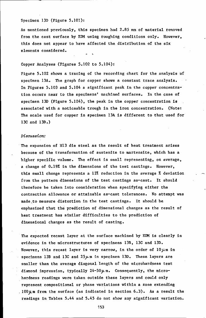
Specimen 130 (Figure 5.101):
As mentioned previously, this specimen had 2.85 mm of material removed
from the cast surface by EDM using roughing conditions only. However,
this does not appear to have affected the distribution of the six
elements considered.
Copper Analyses (Figures 5.102 to 5.104):
Figure 5.102 shows a tracing of the recording chart for the analysis of
specimen 13A. The graph for copper shows a constant trace analysis.
In Figures 5.103 and 5.104 a significant peak in the copper concentra
tion occurs near to the specimens' machined surfaces. In the case of
specimen 130 (Figure 5.104), the peak in the copper concentration is
associated with a noticeable trough in the iron concentration. (Note:
The scale used for copper in specimen 13A is different to that used for
13C and 130.)
Diseussion:
. The expansion of H13 die steel as the result of heat treatment arises
because of the transformation of austenite to martensite, which has a
higher specific volume. The effect is small representing, on average,
a change of 0.19% in the dimensions of the test castings. However,
this small change represents a 12% reduction in the average % deviation
from the pattern dimensions of the test castings as-cast. It should
therefore be taken into consideration when specifying either the
contraction allowance or attainable as-cast tolerances. No attempt was
made ,to measure distortion in the test castings. It should be
emphasized that the prediction of dimensional changes as the result of
heat treatment has similar difficulties to the prediction of
dimensional changes as the result of casting.
The expected recast layer at the surface machined by EDM is clearly in
evidence in the microstructures of specimens 13B, 13C and 130.
However, this recast layer is very narrow, in the order of 10jlm in
specimens 13B and 13C and 25j"m in specimen 130. These layers are
smaller than the average diagonal ·length of the microhardness test
diamond impression, typically 24-30j"m. Consequently, the micro
hardness readings were taken outside these layers and could only
represent compositional or phase variations within a zone extending
. 100}lm from the surface (as indicated in section 6.3). As a result the
readings in Tables 5.44 and 5.45 do not show any significant variation.
153

The microstructure of specimen 13D, Figures 5.94 and 5.95, clearly
demonstrates the greater surface roughness and thicker recast layer
resulting from'the higher current used during EDM roughing operations.
The associated higher surface temperature is probably responsible for
the electrode copper diffusion into the specimen, which has occurred to
a far greater extent than that found in specimen 13C. In specimen 13B
the peak in the copper concentration occurs within 10Jim of the
surface, whereas in specimen 13D the peak occurs at about 25~m from
the surface. The peak concentration of copper in specimen 13D was
estimated to be about 7%, which is almost double that in specimen 13C.
Copper is not usually added to alloy steels, but its effect in both low
and high chromium cast irons is to suppress pearlite, which it does
most effectively in the presence of 0.5 to 2.0% molybdenum.
The appearance of copper in the surface layer of the machined specimens
was expected as the result of diffusion from the copper electrode and
conforms with other findings (112). Apart from this significant
feature, no other marked changes were observed in the six principal
elements considered. In the case of carbon this was unexpected as, in
the case of the as-cast specimens, decarburisation might have been
expected (60) and, in the case of machined specimens, carbon migration
(112,113) or carbon pick-up from the dielectric (89) might have been
expected.
The peaks in concentration level observed in the graphs generally occur
in relation to the elements chromium, molybdenum and vanadium, each of
which is a strong carbide former. It is reasonable, therefore, to
assume that these peaks represent the presence of carbides in the
interdendritic spaces scanned by the electron beam. The association
between peaks for these elements suggests that complex carbides of
these elements were formed. However, no associated peak was observed
in the concentration level of carbon.
The Experimental Officer responsible for the EPMA had, from the outset,
expressed doubts about the equipment's capability to produce accurate
results for low atomic number elements such as carbon. The absence of
any detectable trends or changes in carbon level in these results would
tend to confirm the Officer's pessimism.
In the absence of reliable data for carbon, any conclusions about the
influence of EDM on the as-cast surface structure of the die steel must
154

be limited. The analysis for the other elements has not revealed any
significant difference between the immediate surface zone and the zone
underlying it, except in the case of copper. The microstructural
evidence shows that the recast layer produced by the EDM operation is
quite shallow. As it would be normal practice to finish the surface by
polishing, it is highly likely that the recast layer would be removed
by this operation.
In this investigation an attempt was made to establish the effects of
EDM on the as-cast surface structure. However, it should be noted that
the EDM operation could be performed after heat treatment. In view of
the changes in dimensions produced by heat treatment, it might be
considered preferable to conduct the finishing operation after heat
treatment. Under these circumstances, quite different metallurgical
changes could occur. Whilst this aspect is clearly of relevance to the
production of cast dies, it was not examined in this investigation.
155

Table 6.11: Deviation from Pattern Dimensions after Heat Treatment: Stepped Block
Pattern 1 2 3 13 Dimension Dimension Dimension % Dev Dimension % Dev Dimension % Dev Dimension % Dev
a 74.98 74.37 -0.81 74.18 -1.17 74.39 -0.79 - -b 49.87 49.42 -0.90 49.54 -0.66 49.57 -0.60 49.14 -1.46
c 24.92 24.83 -0.36 25.10 +0.72 24.99 +0.28 24.72 -0.80
d 48.30 47.81 -1.01 47.65 -1.35 - - - -e 73.27 72.24 -1.41 72.18 -1.49 - - 72.20 -1.46
f 98.30 96.53 -1.80 96.67 -1.66 - - 96.65 -1.68
Average % Deviation -1.05 -0.94 -0.37 -1.35 .
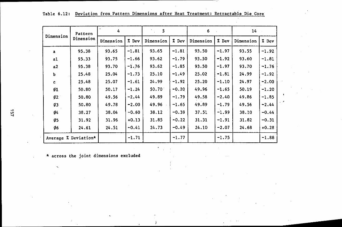
Table 6.12: Deviation from Pattern Dimensions after Heat Treatment: Retractable Die Core
Pattern 4 5 6 14 Dimension Dimension Dimension % Dev Dimension % Dev Dimension % Dev Dimension % Dev
a 95.38 93.65 -1.81 93.65 -1.81 93.50 -1.97 93.55 -1.92
a1 95.33 93.75 -1.66 93.62 -1. 79 93.50 -1.92 93.60 -1.81
a2 95.38 93.70 -1.76 93.62 -1.85 93.50 -1.97 93.70 -1. 76
b 25.48 25.04 -1. 73 25.10 -1.49 25.02 -1.81 24.99 -1.92
c 25.48 25.07 -1.61 24.99 . -1. 92 25.20 -1.10 24.97 -2.00
01 50.80 50.17 -1.24 50.70 -0.20 49.96 -1;65 50.19 -1.20
02 50.80 49.56 -2.44 49.89 -1. 79 49.58 -2.40 49.86 -1.85
03 50.80 49.78 -2.00 49.96 -1.65 49.89 -1.79 49.56 -2.44
04 38.27 38.04 -0.60 38.12 -0.39 37.51 -1.99 38.10 -0.44
05 31.92 31.96 +0.13 31.85 -0.22 31.31 -1.91 31.82 -0.31
06 24.61 24.51 -0.41 24.73 -0.49 24.10 -2.07 24.68 +0.28
Average % Deviation* -1. 71 -1. 77 -1. 75 -1.88
* across the joint dimensions excluded
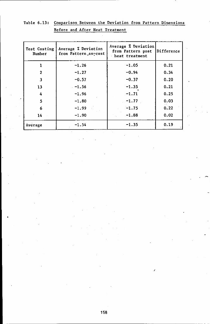
Table 6.13: Comparison Between the Deviation from Pattern Dimensions
Before and After Heat Treatment
Test Casting Average % Deviation Average % Deviation
Number from Pattern_as7cast from Pattern post Difference heat treatment
1 -1.26 -1.05 0.21
2 -1.27 -0.94 0.34
3 -0.57 -0.37 0.20
13 -1.56 -1.35 0.21 , 4 -1.96 -1.71 0.25
5 -1.80 -1.77 0.03
6 -1.99 -1. 75 0.22
14 -1.90 -1.88 0.02
Average -1.54 -1.35 0.19
,
158
6.6 DISCUSSION SUMMARY
The mould material evaluation programme had as its major objective the
establishment of an acceptable mould firing regime for composite mould
production. The effect of firing temperature and time at firing
temperature on retained strength was demonstrated for both the facing
and backing materials. The suggestion that a minimum firing o temperature of 1000 C was necessary to develop maximum strength in the
facing material was confirmed. However, it was also shown that this
strength was not that much higher than that obtained by firing to
7500 C. Furthermore, it was established that the high temperature
properties and inertness of the material fired at 7500 C were acceptable
for the requirements of test casting production. A maximum firing o temperature of 750 C and time at temperature of two hours were selected
as the ideal compromise solution for the production of composite
moulds.
The major emphasis of the experimental work on metallurgical processing
was the establishment of the most suitable processing conditions for
producing castings free from the pitting defect. Whilst the approach
adopted for evaluation was inherently subjective, it provided clear
recommendations for suppressing this defect. For example, it was
established that a high mould temperature and/or metal pouring
temperature exacerbated the pitting defect. On the other hand, the
problem was reduced when a deoxidiser was added to the melt. However,
the defect could only be eliminated from castings produced in mu11ite
moulds when pouring and cooling occurred under an inert gas cover.
Alternatively, the moulds could be cast in air providing 10 weight %
graphite was incorporated in the mould facing material. The advantage
of a scale-free casting was,however, only obtained when using an inert
gas atmosphere. The programme of experiments also provided evidence
that grain refining additions could be used to reduce the grain size of
cast H13 die steel. Finally, evidence was obtained which suggested
that the 'casting skin' was softer than the core structure of the ingot
castings.
The objectives of the test casting evaluation programme included the
confirmation of the findings of the work on mould material evaluation
and metallurgical processing. In addition, the programme was directed
at providing information about the effect of process variables on the
dimensional accuracy and surface quality of the test castings. The
major variable under consideration was the mould material/atmosphere
combination. By using four different test casting designs, of
different size and weight, the influence of shape and size on the
casting quality could be assessed. An attempt was made to standardise
other variables. All melts were deoxidised with 0.5% Stellagen 1 and
with only two exceptions the.ma~imum metal temperature in the furnace
was maintained at 16500 e. Whilst an attempt was made to pour the
castings at around 15400 e, pouring temperatures varied between 14830 e-o 1586 e, presenting another variable whose effect could be assessed.
The moulds were all maintained at ambient temperature for pouring.
The results of the test casting evaluation were not definitive and did
not show clear confirmation of the results obtained from the
metallurgical processing programme. It was not possible to show that
anyone of the mould material/atmosphere combinations produced a
superior casting quality. Especially disappointing was the appearance
of the pitting defect in test castings which had been processed in a
nitrogen atmosphere or a mould facing containing graphite. However,
limitations in practice may have caused the problem and were discussed
earlier.
Pouring temperature was expected to exert a significant influence·on
the quality of test castings. However, the expected association
between pouring temperature and % deviation and mean Ra did not occur,
although association did occur between pouring temperature and mean Wa
for the group of castings excluding the retractable die cores.
Subjective visual assessment of the test castings suggested that a o minimum pouring temperature of 1540 e should be used to prevent cold
laps and/or loss of definition. It is more difficult to propose a safe
maximum pouring temperature. Metal penetration was observed on two o 0 castings poured respectively at 1555 e and 1586 e. However, these
castings were produced in mould facing material containing graphite
which, as explained earlier, may be the cause of the observed defect.
A tentative guide for pouring temperature, in the absence of objective
information, could be 15500 e ~ 10oe.
The most significant variable, established by tests for association,
was that of casting weight, which was shown to have a direct influence
on mean Ra values for the group of fifteen test castings. When the
160
retractable die core castings were discounted, association existed
between casting weight and mean Ra, and between casting weight and %
deviation from the pattern dimensions.
Although a value for contraction allowance was determined
experimentally, it did not prove possible to use the value to
differentiate between the contributions of contraction and process to
the % deviation from pattern dimensions. This was because the
experimentally determined value of 1.64% for contraction allowance was
so close to the mean % deviation from pattern dimension of 1.65%.
In the programme of work to evaluate the effect of finishing
procedures, it was established that the adopted heat treatment
procedure resulted in growth in the test castings which, on average,
represented about 0.19% of the original pattern dimension. The results
of the experiments to establish the influence of EDM on cast surface
structure were less conclusive. The expected recast layer was present
but because it was very shallow, especially when fine finishing
conditions were used, it was not possible to establish the micro
hardness of the layer using a sample face perpendicular to the machined
surface.
Electron probe microanalysis revealed the pick-up of copper by the die
steel from the EDM electrode. However, the scans did not reveal any
significant trends in the distribution of the six elements considered
between the as-cast surfaces or those machined by EDM. In this respect
it was unfortunate that the analysis for carbon could not be considered
to be reliable.
No evidence was found to suggest that the as-cast surface possessed
special properties which merited retention. In addition, the results
did not show any reason why the surface skin should not be removed by
EDM if finishing was required. As it would be normal practice to
finish the cavities by polishing, the very shallow recast layer would
be substantially removed before the die was used in service.
161

CHAPTER SEVEN
CONCLUSIONS
Mould Material Evaluation:
1 A blend of -8 + 16; -30 + 80; and -120 mesh grades of malachite
blended in the ratio of 3:1:1 and mixed with 6 weight % Cl12 sodium
silicate provides a suitable backing material for composite mould
manufacture. The material possesses good as-gassed strength and
after firing to 750·C, and holding at temperature for two hours, has
excellent retained strength, good permeability and is inert.
2 A blend of -8 + 16; -30; and -100 mesh grades of mullite blended in
the ratio of 1:1:2 and mixed in the ratio of 1 kg of mullite blend
to 225 gm of ethyl silicate and 12 gm of 10% ammonia in water
solution produces a mobile slurry suitable for mould facing material.
Whilst this material develops higher retained strength and increased
high temperature properties when fired to 1000·C, the properties
developed by firing to 750·C are considered to be adequate for the
application.
3 Although the bond which develops between the backing and facing
material has relatively low strength, it is sufficiently strong to
prevent separation of the two materials during mould processing.
Metallurgical Processing:
4 Ingot castings produced in mullite moulds and cast in air exhibited
the pitting defect. The severity of the defect was found to
increase with an increase in mould preheat temperature and metal
pouring temperature. The severity was found to decrease when the
melt was treated with a deoxidiser.
5 Ingot castings produced in a mullite mould facing material
containing 10 weight % graphite and cast in air were found to be
free from the pitting defect.
6 Ingot castings produced in a mullite mould, cast in and cooled in an
inert gas atmosphere were also found- to be free from the pitting
defect. In addition, the as-cast surface was substantially free
from oxide scaling.
162
7 The addition to the melt of a grain refining agent, based on a
mixture of ferro-titanium and ferro-niobium, increased the grain
count in treated ingot castings.
8 The hardness of the as-cast subsurface layer of the ingot castings
was found in' general to De lower than that for the casting centres.
Test Castings Evaluation:
9 Considering the results for all fifteen test castings a statistically
significant association, at the 5% level, was found to exist between:
mean Ra and casting weight; and mean Ra and mean Wa.
10 When the results for the retractable die core castings were excluded
from consideration a statistically significant association, at the
5% level, was found to exist between: mean Ra and casting weight;
mean Ra and mean Wa; % deviation from the pattern dimensions and
casting weight; and mean Wa and pouring temperature.
11 No evidence was found to suggest that anyone of the three mould
material/atmosphere combinations employed produced significantly
different dimensional accuracy or surface finish results. Further
more, it could not be proven conclusively that the combinations of:
a mullite mould and inert gas atmosphere; and a mullite mould facing
c~ntaining 10 weight % graphite and casting in air; would result in
a casting free of the pitting defect.
12 An experimentally determined value for contract~on allowance of
1.64% was established. However, because this vaiue was so close to
the value of 1.65% for the mean % deviation from the pattern
dimension value, it was not possible to differentiate between the
influence of the contraction allowance and process variables on the
overall dimensional accuracy of the test castings.
13 A tentative suggestion for pouring temperature range would be 1550·C
± 10·C.
Finishing Procedures:
14 The recommended heat treatment procedure enables the cast H13 die
steel to develop an average hardness value of 53 Rc.
163
15 The recommended heat treatment procedure resulted in casting growth
equivalent, on average, to a deviation of 0.19% of the original
pattern dimension.
16 Electrical discharge machining of the cast H13 die steel results in
the formation of a shalrow'recast layer. When fine finishing
conditions were employed this layer was approximately 10 ~m thick.
17 Electron probe microanalysis did not reveal any difference in
composition between the as-cast surface material of castings
produced using the different mould material/atmosphere combinations.
Furthermore, no difference in composition was found between the as
cast surface layer and the machined (EDM) surface layer, other than
the pick-up of copper from the EDM electrode. However, it must be
stated that the analysis for carbon may be unreliable.
164
CHAPTER EIGHT
SUGGESTIONS FOR FURTHER WORK
1 It must be accepted that the sample size of fifteen castings used
for the test casting eva!uation programme was small in statistical
terms. Where association was shown to exist between variables, it
was at the risk of a 1 in 20 chance of being wrong. To reduce this
risk and confirm, or otherwise, the associations obtained it would
be prudent to produce additional test castings. Whilst the
accuracy of interpretation will increase with the number of castings
produced, a practical limit to this number must be applied. By
producing a second batch of fifteen castings, a sample of thirty
test castings would be available and this should markedly improve
the validity of the statistical tests.
2 The mould material evaluation was restricted to a consideration of
the effects of temperature on the properties of a plain a1umino
silicate refractory bonded with ethyl silicate. If a facing material
incorporating 10 weight % graphite were to be adopted it would be
valuable to assess the properties of this material in a similar
manner to that reported in this investigation.
3 The procedure for producing the composite moulds used in this
investigation was time consuming and required significant pr~ctica1 expertise. That the Shaw Process provides superior dimensional
accuracy and surface finish to conventional sand practice is not
disputed. However, it would be interesting to compare the quality
of castings produced using silica free aggregates bonded with co1d
set binder systems with those produced in this investigatiQn.
Clearly, if the quality of such castings approached that attainable
in castings produced by the Shaw Process, there would be little
point in paying the cost premium associated with the latter,
especially if some machining was in any case going to be necessary.
4 No attempts have been made within this investigation to assess the
wear characteristics of the cast H13 die steel, eithe'r by a
sim~lation technique or industrial trials. A point of interest in
such trials would be the attempt to compare the performance of as
cast die impressions with those which have required surface removal
165

by EDM, rather than to compare the performance of cast material with
wrought material. In this respect a comparison of the effect of
conducting EDM before and after heat treatment would also be of
interest.
166
REFERENCES
1 Lange K; Technical Paper No MF72-104, ASTME, 1972.
2 A study of the UK Die and Mould Manufacturing Industry. Ministry
of Technology, 1970.
3 Metals Handbook, Volume 1, ASM, P 637.
4 Metals Handbook, Volume 5, ASM, P 2B.
5 Draft Report: The Potential for Scientific Research in the
Techniques Employed in the Manufacture of Die and Moulds. Gough
and Sweeney, 1974.
6 Editorial, Machinery and Production Engineering, 1971, V llB, P Bl.
7 Hamilton F W; Machinery and Production Engineering, 1971, V llB,
pp IB7-189.
8 Peel E W; Metal Treatment, 1962, V 29, pp 421-440.
9 Smith C H; Metal Treatment, 1962, V 29, pp 515-523.
10 St~ren S, Ebbesen J, Slut£s J and Saetre I; Machine Tool Design
and Research, Proceedings of 15th Conference, Birmingham, 1974,
pp 473-47B.
11 Thomas A; Metal Forming, 1971, V 3B, (2), pp 41-45.
12 Coates J; Metal Forming, 196B, V 35, (11), pp 320-329.
13 Eminger Z and Kose1ev V; Cast Tools, Artia, Prague, 1957.
14 Jones R N; Metal Treatment, 1966, V 33, n 244, p 25.
15 Gaucheron M; Estam Forge, 1967, BISI Translation 6327, November
196B.
16 Stutzman G D; Technical Paper No CM69-236, SME, 1969.
17 Madono 0; SAE Journal, 1963, V 71, n 6, p 96.
18 Murao T and Mino H; Modern Casting, 1967, V 48, n 3, p 140.
19 Szende Gy; Bany es Koh Lapok (Ontode), 1976, V 27, n 3, p 63.
BISI Translation 14700, October 1976.
20 Bazzano E; Castings, 1970, V 16, n 5, p 24.
21 Lubalin I; Cast Forging Dies, paper presented to ASTME Detroit,
Michigan, 2 Feb, 1965, Avnet-Shaw.
22 Pfaff W G; Technical Paper No 717, SME, 1965.
167
23 Stutzman G D; Precision Metal Moulding, 1965, V 23, n 6, p 52.
24 Stutzman G D; Technical Paper No CM67-536, SME, 1967.
25 Huskonen W D; Foundry, '1970, V 98, nIl, p 38.
26 Shaw C; Foundry Trade Journal, 1946, V 78, (1534), p 31.
27 Greenwood R; American Patent 3,172,176.
28 Lubalin I and Christensen R J; Modern Casting, 1960, V 38, (4),
P 83.
29 Emblem H G; Trans and Journal British Ceramic Society, 1975, V 74,
(23), p 660.
30 Jones K, Biddle K D, Das A K and Emblem H G; Tin and Its Uses,
1979, V 119, plO.
31 Emblem H G; Foundry Trade Journal, 1972, V 132, (2884), P 379.
32 Lawrence W G; Modern Casting, 1960, V 38, (2), P 109.
33 Wales W F; Trans AFS, 1973, v 81, P 249.
3~ Paters on S; SAE Trans, 1967, V 75, paper 660645, p 263.
35 Kingery W D; Introduction to Ceramics, Wiley, London 1976.
36 Budworth D W; An Introduction to Ceramic Science, Pergammon,
Oxford 1970.
37 Butler M J; British Plastics, 1970, V 43, (6), p 144.
38 Ba1inskii V R, Lebedeva V G and Sitnichenko A I; Russian Castings
Production, 1972, p 421.
39 Winter DB; Foundry Trade ,Journal, 1964, V 116, (2474), P 427.
40 Dittrich W; Giesserei, 1972, V 59, (8), P 239.
41 Dunlop A; American Patent 2,931,081.
42 Luba1in I J; American Patent 3,242,539.
43 Scott R K; American Patent 3,213,497.
44 01sen C F; ASTME Technical Paper CM69-235, 1969.
45 Prasad J S and Watmough T; Trans AFS, 1969, V 77, p 289.
46 Lubalin I; ASTME Technical Paper CM67-627, 1967.
47 Lubalin I' , Modern Casting, 1965, V 47, (ll, P 777.
48 Dunlop A; Foundry Trade Journal, 1962, V 113, (2395), P 541.
168

don 49 Lin~P Hand Bi11ington J C; J Iron and Steel Institute, 1969,
V 207, (3), p 340.
50 Van Eeghem J and De Sy A; Modern Casting, 1964, V 45, (4), p 142.
51 F1inn R A and Van V1ack L H; Trans AFS, 1959, V 67, p 295.
52 Jha J; Tool Alloy Steels, 1977, VII, (10), P 335.
53 Church N, Weiser P and Wa11ace J F; Modern Casting, 1966, V 49,
(4), p 129.
54 Phi11ips G C and DeMaine F J; ASTME Technical Paper CM71-159, 1971;
55 Murao T; Foundry Trade Journal, 1961, V 110, (2304), P 149.
56 Torry A; Metal Treatment, 1962, V 29, (11), p 451.
57 Doremus G E and Loper'C R; Trans AFS, 1970, V 78, p 338.
58 Shaw C; American Patent 2,935,772.
59 Duffen L Wand Jarman D C; The British Foundryman, 1960, V 53,
(2), p 79.
60 Yardinici G, Fischer F and K1ein E; Proc 4th World Conference on
Investment Casting, June 1976.
61 de 01iveira Pinto Ed C and Gouvera J A; Met ABM, 1970, V 26,
(157), p 927.
62 Tay10r L S; Foundry Trade Journal, 1965, V 119, (2534), pIS.
63 Scott R K; American Patent 3,399,067.
64 Pikman A A, Lyakhovich L S, Po1yakov B Z and Surkov V V; Russian
Castings Production, 1976, p 253.
65 Neumayer P; ASTME Technical Paper MR69-714, 1969.
66 Marsh R; Production Engineer, 1977, V 56, (11), p 18.
67 Crooka11 J R; Engineers' Digest, 1978, V 39, (11), p 39.
68 Buck10w I A and Co1e M; Metallurgical Reviews, 135, 1969, p 103.
69 Crooka11 J Rand Heuve1man C J; Ann CIRP, 1971, V 20, (2), p 113.
70 Gibbon I M; Metals and Materials, 1969, V 3, (8), p 308.
71 Siege1 E W; ASTME Technical Paper 971B, 1965.
72 Smith G V; Proc Conference on Electrical Methods of Machining,
Forging and Coating, March 1970.
169
73 Wack L C; US Met Process and Fab Seminar, March 1974.
74 Gough P J C; Engineers' Digest, 1976, V 37, (10), p 9.
75 Neumayer P; ASTME Technical Paper MR68-906, 1968.
76 Carver B G; Sheet Metal Industries, 1966, V 43, (8), p 600.
77 Gerber H R; SME Technical Paper MR76-817, 1976.
78 Wick C H; Machinery and Production Engineering, 1970, V 116,
(2988), p 242.
79 Filshie I S; ASTME Technical Paper MR72-190, 1972.
80 Greatorex G L; SME Technical Paper MR76-907, 1976.
81 Hockenby T 0; SAE Paper 680635, meeting October. 1968.
82 Crookall J R and Lee P W; Proc Machine Tool Design and Research
Conference, Birmingham 1974, p 385.
83 Stanislao J and Rickman M H; Precision Metal, 1971, V 29, (3),
p 47.
84 Clark T; American Machinist, 1970, V 114, (11), p 92.
85 Gough P J C; Trans Plascic Institute, 1963, V 31, (94), p 86.
86 Venkatesh V C; Proc All India Machine Tool Design and Research
Conference, April 1972, p 639.
87 Walton L Rand Wendell C R; Tool and Manufacturing Engineer, 1965,
V 54, (3), p 69.
88 Wendell C Rand Walton L R; American Machinist, 1964, V 108, (4),
p 101.
89 Maserelli Land Marchionni M; Metals Technology, 1977, V 4, (2),
p 100.
90 Tomko G M; ASTME Technical Paper MR73-198, 1973.
91 Kostev P; Proc Conference on Materials Technology, June/July 1975,
p 231.
92 Barash M M; Metals Engineering Quarterly, 1965, V 5, (4), p 48.
93 Wallbank J; Metallurgia, 1980, V 47, (1), p 4.
94 Code of Practice for Heat Treatment of 5% Chromium Die Steels (H13
Type). Pamphlet published by the Zinc Alloy Die Casters
Association, London, 1975.
1~
95 Wilson R; Metallurgy and Heat Treatment of Tool Steels, McGraw-Hill,
London, 1975, p 148.
96 Ibid, P 286.
97 Ibid, P 67.
98 Nicholas K E L; The C02 /Siiicate Process in Foundries, BCIRA,
Alvechurch, 1972, p 148.
99 Molochite Technical Handbook, English China Clays Co Ltd, p 4.
100 Towers H; Iron and Steel, 1955, 28, 3, P 101.
101 Duckworth W E; Statistical Techniques in Technological Research,
Methuen and Co Ltd, London, 1968, p 4.
102 Ibid, P 27.
103 Beeley P R, Baker A J, Blackmore P A and Se gal A; Metals Technology,
1981, 8, 7, P 268.
104 Duckworth W E; Statistical Techniques in Technological Research,
Methuen and Co Ltd, London, 1968, p 5.
105 Ibid, plO.
106 Metals Handbook, Volume 7 - Atlas of Microstructures of Industrial
Alloys, 8th Edition, ASM, Ohio, 1972, p 116.
107 A Guide to the Solidification of Steels, Jernkontret, Stockholm,
1977, P 58.
108 Harvie A and Beattie J S; The Production Engineer, 1978, 57, 2,
p 25.
109 Swing E; Trans AFS, 1963, 71, p 454.
110 Paterson Wand Schneider PH; Modern Castings, 1965, 47, I, p 857.
111 Dagnall M A; Exploring Surface Texture, Rank Taylor Hobson,
Leicester, 1980, p 19.
112 Davies C; J Materials Science, 1976, 11, 7, P 1301.
113 Lloyd H K and Warren R H; J Iron and Steel Institute, 1965, 203,
3, p 238.
171

APPENDIX ONE
MATERIALS USED IN THE CERAMIC SLURRY PROCESS
1 Guidelines for Refractory Material Selection
The material should:
be clean and pure - to prevent contamination and metal-mould reaction;
be refractory - to give a good hot strength;
have low thermal expansion - to reduce spalling and improve
dimensional accuracy.
In order of decreasing refractoriness, the materials which meet these
requirements are:
fused a1umina
tabular a1umina
calcined a1umina
fused silica
mullite
sillimanite
zircon flour
molochite
silica flour
potters flint
Thermal Expansion:
In general, high thermal expansion and large volume changes at
inversion points are detrimental. It is desirable to match the
expansion of facing and backing mould materials.
Specific Gravity:
In general, the specific heats of these refractory materials are very
similar, therefore the specific gravity indicates the amount of heat a
given volume of material can absorb for a specified temperature rise.
The'higher the specific gravity the more heat will be absorbed.
Therefore a material such as zircon, with a high specific gravity,
may have an effectively higher refractoriness than, say, sil1imanite
or mu1lite, despite its lower dissociation temperature/melting point.
172
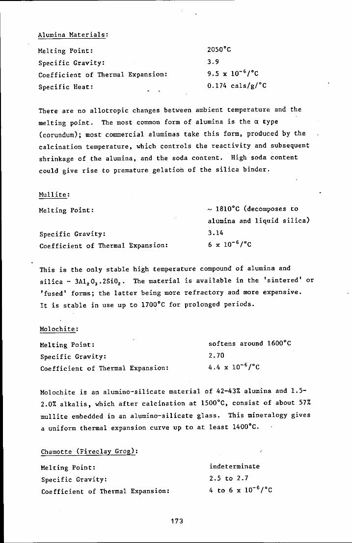
Alumina Materials:
Melting Point:
Specific Gravity:
Coefficient of Thermal Expansion:
Specific Heat:
2050·C
3.9
9.5 x 1O- 6 {"C
0.174 cals/g/·C
There are no allotropic changes between ambient temperature and the
melting point. The most common form of alumina is the a type
(corundum); most commercial aluminas take this form, produced by the
calcination temperature, which controls the reactivity and subsequent
shrinkage of the a1umina, and the soda content. High soda content
could give rise to premature gelation of the silica binder.
Mullite:
Melting Point:
Specific Gravity:
Coefficient of Thermal Expansion:
- 1810·C (decomposes to
a1umina and liquid silica)
3.14
6 x 10- 6 {"C
This is the only stable high temperature compound of a1umina and
silica - 3A1.0,.2SiO •. The material is available in the 'sintered' or
'fused' forms; the latter being more refractory and more expensive.
It is stable in use up to 1700·C for prolonged periods.
Mo10chite:
Melting Point: softens around 1600·C
Specific Gravity: 2.70
Coefficient of Thermal Expansion: 4.4 x 1O- 6 {"C
Mo10chite is an a1umino-si1icate material of 42-43% a1umina and 1.5-
2.0% alkalis, which after calcination at 1500·C, consist of about 57%
mu11ite embedded in an a1umino-si1icate glass. This mineralogy gives
a uniform thermal expansion curve up to at least 1400·C.
Chamotte (Firec1ay Grog):
Melting Point: indeterminate
Specific Gravity: 2.5 to 2.7
Coefficient of Thermal Expansion: 4 to 6 x 1O- 6 rC
173

This product is made by calcining high alumina clays (38-45% AI,O,) or
by crushing used fireclay bricks. The product is similar to molochite
in many respects but contains many more impurities - oxides of iron,
sodium, potassium, calcium and magnesium. Its refractoriness will , suffer due to impurities and it will have a refractoriness lower than
that of molochite.
Zircon:
Melting Point:
Specific Gravity:
Coefficient of Thermal Expansion
dissociates* around l600·C
4.2 to 4.6
4.5 x 10⁻⁶/°C
* there is disagreement in the literature on this point; claims are
made of melting points as high as 2480·C, whereas counter claims
suggest that zircon dissociates around 1600·C into zirconia (ZrO,) and
silica glass. The latter claim is believed to be more correct.
The natural grain or sand have particle sizes all + 200 mesh, zircon
flour is ground zircon sand. The high specific gravity of zircon
gives it a high heat absorption characteristic.
2 Prehydrolysed Ethyl Silicate
The development of methods of preparing ethyl silicate hydrolysates
having a long storage life has made hydrolysed ethyl silicate solutions
commercially available. These solutions are referred to as
'prehydrolysed' ethyl silicate. They are supplied as ready to use
hydroxylated forms of ethyl silicate in active form capable of forming
refractory bonds.
Several types of prehydrolysed ethyl silicate are commercially
available and they are generally formulated to cater for the widest
possible application in ceramic mould-building operations.
As well as eliminating the need for the foundry to prepare its own
hydrolysed solutions they offer the advantages of consistent quality,
long shelf life and, in some cases, improved functional performance.
1n
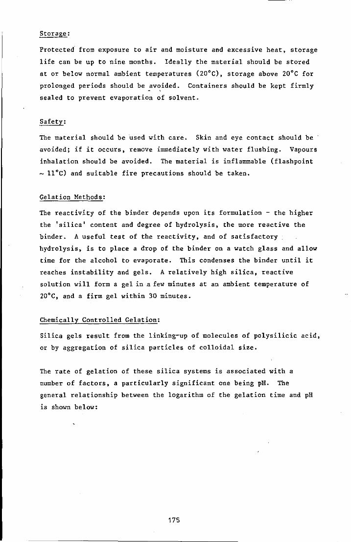
Storage:
Protected· from exposure to air and moisture and excessive heat, storage
life can be up to nine months. Ideally the material should be stored
at or below normal ambient temperatures (20·C), storage above 20·C for
prolonged periods should be avoided. Containers should be kept firmly
sealed to prevent evaporation of solvent.
Safety:
The material should be used with care. Skin and eye contact should be
avoided; if it occurs, remove immediately with water flushing. Vapours
inhalation should be avoided. The material is inflammable (flashpoint
- II·C) and suitable fire precautions should be taken.
Gelation Methods:
The reactivity of the binder depends upon its formulation - the higher
the 'silica' content and degree of hydrolysis, the more reactive the
binder. A useful test of the reactivity, and of satisfactory
hydrolysis, is to place a drop of the binder on a watch glass and allow
time for the alcohol to evaporate. This condenses the binder until it
reaches instability and gels. A relatively high silica, reactive
solution will form a gel ina few minutes at an ambient temperature of
20·C, and a firm gel within 30 minutes.
Chemically Controlled Gelation:
Silica gels result from the linking-up of molecules of polysilicic acid,
or by aggregation of silica particles of colloidal size.
The rate of gelation of these silica systems is associated with a
number of factors, a particularly significant one being pH. The
general relationship between the logarithm of the gelation time and pH
is shown below:
175

I
/' /
~I
-
CD E F ID Cl
/ \ /
Cl
.3
/ \ / \
\ / '" v
o 2 3 4 5 6 7 pH
Log Gel Time Versus pH of ~inders (reproduced from source 4)
Maximum stability, or longest time to gel, occurs at a pH value between
1.5 and 2: gelling is most rapid at pH 5-6 and the systems set
irreversibly. Below 1.5 the stability decreases again, while above pH
6 it increases again up to a pH of 11. These are general trends,
actual gelation time depends on other factors too.
Binder Quality Control Procedures
Relevant tests which can be used as quality acceptance tests for the
liquid prehydrolysed binders include:
I Ability to Gel
II Gel Time
III Acidity
IV pH Value
I Ability to Gel:
The purpose of this simple test is to check that the material has
been hydrolysed.
176
11 Gelation Time:
The purpose of the test is to determine whether or not the ethyl
silicate has been properly hydrolysed. The addition of a
predetermined amount of a suitable gelling agent to a fixed
quantity of satisfactory b,inder liquid should, at a constant
temperature, result in a gel within certain time limits.
III Acidity:
The range 0.03% to 0.30% is preferred. At very low acid
concentrations silica tends slowly to settle out of solution.
High acid concentration causes premature gelation of the entire
solution.
IV pH Value:
The term pH implies that measurements are taken in an aqueous
system. However, the pH of ethyl silicate 40 and its hydro1ysates
can be measured by the usual means. The simplest method of
carrying out pH measurements is by using Universal Indicator
Solution, or the narrow range Universal pH papers.
3 Recommended Ceramic Slurry Moulding Mixes
Monsanto:
To form a strong matrix, 30 to 50% of fines must be present in the
filler and the remainder should be as coarse as the shape to be cast
will permit. A typical filler formulation is:
50% - 30 + 80 mesh si11imanite
50% - 200 mesh si11imanite
This should be mixed in the rat'io of 0.45 kg of filler to 90 m1 of
binder.
Clino Foundry Supplies:
Recommend> 50% fines in the mix. Alternative mix formulations
recommended are:
(a) 6 parts
4 parts
1 part
100 mesh mullite
30 + 80 mesh mo1ochite
16 + 30 mesh mo1ochite
177

(b) 80%
20%
- 100 mesh mullite
- 30 + 80 mesh molochite
Associated Engineering Developments Ltd:
Recommend that only mullite refractories be used for precision casting
die steels. Suggested mix formulation:
50% - 100 mesh mullite
40% - 16 +' 22 mesh mullite
5% - 22 mesh mullite
5% - 8 + 16 mesh mullite
Leeds University, Department of Metallurgy:
In a parallel SERC funded research project, the following mix
formulation was found to be satisfactory:
25% 8 + 16 mesh molochite
25% - 30 + 60 mesh molochite
25% - 200 mesh molochite
The refractory filler was blended at the rate of 1 kg to 250 ml of
ethyl silicate and gelled using a 2% ammonia solution.
Sources of Information
1 Molochite Technical Handbook. English China Clays Co Ltd.
2 Cawoods Raw Materials for the Refractories Industries. Cawoods
Refractories Ltd.
3 Investment Casting: Mould Refractories and UK Suppliers. BICTA.
4 Binders and Applications in the Precision Foundry Industry.
Monsanto Ltd.
5 Investment Casting: Data Sheets On Slurry Control. Vol 11 Alcohol
Based Binders and Slurries. BICTA.
,

APPENDIX TWO
THE CO2/SILICATE PROCESS
In the CO2 /Silicate process a refractory aggregate is mixed with an
aqueous sodium silicate solution to form a moulding material. After
compact ion around a pattern, carbon dioxide gas is passed through the
material to harden it. Although the process is quite straightforward
to use, certain aspects require careful consideration to ensure moulds
of consistently high quality. The major aspects of importance are
briefly outlined.
Binders:
The production of sodium silicate involves the heating of crushed
silica with sodium carbonate to give a silica-sodium oxide compound.
By careful control and adjustment a sodium silicate solution with a
specific ratio of silica to sodium oxide is produced. In the UK a 2:1
ratio is still most popular, although higher ratio silicates are
available. This ratio, in conjunction with the specific gravity, is
sufficient to characterise the sodium silicate. The specific gravity
of the solution can be altered by adjusting the water content, but the
usual range is lOO· to 140· Twaddell.
Mixing:
Ideally, the mixing operation should:
produce a uniform distribution of the silicate binder, coating all the
grains evenly;
. cause the minimum water evaporation and air drying of the aqueous
sodium silicate;
cause the least rise in temperature throughout the mix.
Most conventional foundry sand mixers are suitable. It is possible to
over mix the silicate bonded material,with the fOllowing disadvantages:
evaporation of the water during mixing will reduce the bench life;
the as-gassed strength will be difficult to control;
there is an incre·ased risk of friability and loss of strength during
storage.
179

Bench Life:
Mixtures containing 2:1 ratio silicates possess a relatively long
bench life, which permits extended usage without a serious reduction
in gassed strengths. When exposed to air a mixture gradually forms a
hard crust, due mainly to th! ~vaporation of water from the binder.
By storing the mixture in sealed containers, the bench life can be
prolonged.
Principles of CO2 Gassing
A fast bonding reaction occurs when CO2 gas reacts with sodium silicate
exposed as a thin film on the surface of the refractory grains.
Several methods for introducing the gas are used in practice and
include:
probe gassing;
hood gassing;
hollow pattern incorporating gassing vents;
vacuum chamber gassing.
CO2/Silicate Reactions
Time Dependence:
With a constant gas flow rate, the strength increases progressively as
the gassing time is extended. In many cases there is an initial period
of SOme seconds at the start of gassing when virtually no strength is
developed. Subsequently, a rapid increase in strength occurs as
gassing continues.
CO2 Flow Rate:
Changing the flow rate at which CO2 gas passes through a refractory
mass has important effects on both the strength of bond obtained and
the distribution pattern of the gas. Finding the best flow rate for
a particular application necessitates a compromise between these two
interests and that of gas economy.
The gas flow rate controls both the as-gassed strength and stored
strength of the material. At high flow rates, 30 litres/minute, "as
gassed strengths are low in comparison with as-gassed strengths
100
developed with a flow rate of 5 litres/minute. On the other hand,
much higher strengths are developed on standing by the material gassed
at a high flow rate.
CO2
Dehydration of Silicates:
The reason for the decrease in as-gassed strength at high CO, flow
rates is a change in the hardening mechanism. CO, gas is very dry
(dew point -40°C) and the gas Can harden aqueous sodium silicate by
two alternative mechanisms:
(i) A chemical reaction involving the formation of a silica hydrogel
bond;
(ii) A physical process in which a glass-like, high viscosity sodium
silicate bond is formed, due to dehydration of the aqueous
silicate by the dry CO, gas.
At low gas flow rates the former mechanism predominates, whereas at
high flow rates it is the latter mechanism which predominates.
Gas Pressure:
The actual pressure of the gas delivered does not appear to have any
influence upon the speed of the hardening process.
Sand Temperature:
Hardening reactions between CO, gas and sodium silicate are temperature
dependent and are greatly retarded by low temperatures. Below IO°C
reaction is extremely slow and the process becomes less economic, due
to the length of time taken and volume of gas consumed before an
adequate bond is obtained.
Another factor influencing the efficient operation of the CO, process
is the increase in viscosity of sodium silicate binders at low
temperatures, which will hinder the uniform distribution of the
silicate during mixing.
High Temperature Properties
A great deal of attention has been given to the high temperature
properties of silicate bonded sands, the main interests being in
methods and materials to improve breakdown and simplify knock-out,
1~
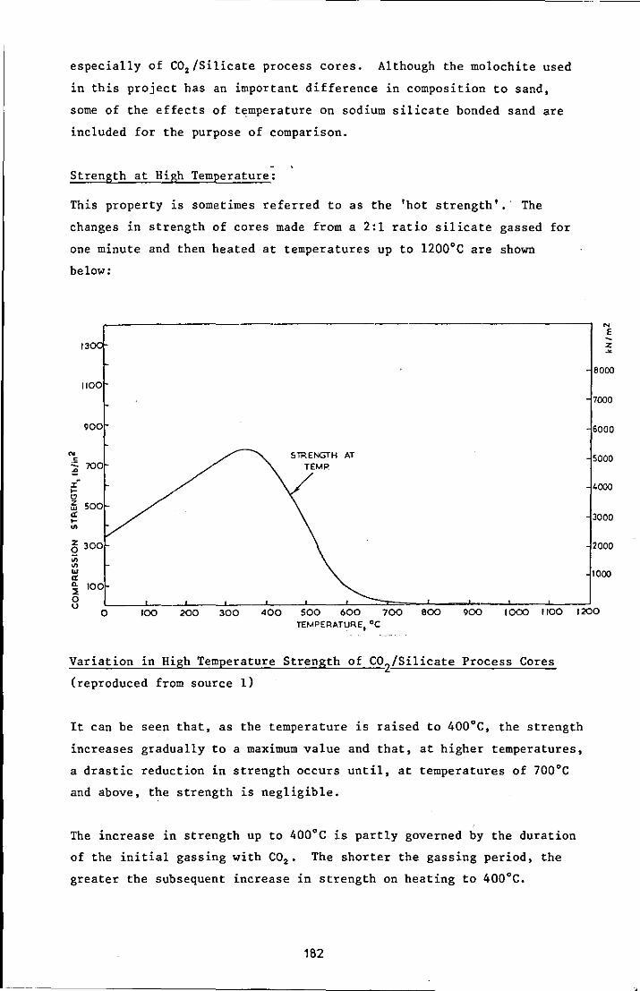
especially of CO2 /Silicate process cores. Although the molochite used
in this project has an important difference in composition to sand,
some of the effects of temperature on sodium silicate bonded sand are
included for the purpose of comparison.
Strength at High Temperature:
This property is sometimes referred to as the 'hot strength'.' The
changes in strength of cores made from a 2:1 ratio silicate gassed for
one minute and then heated at temperatures up to 1200·C are shown
below:
13
1100
900
N < SiRENGTH AT , 700 ~
TEMP
:£ I-CJ z 500 w et I-.. Z 300 Q
'" '" w 0: c- 100 ::! 0
N
E
Z ~
8000
7000
6000
5000
'000
3000
2000
1000
u 0 100 200 300 400 500 600 700 800 900 1000 1100 1200
TEMPERATURE.OC
Variation in High Temperature Strength of CO2/Silicate Process Cores
(reproduced from source 1)
It can be seen that, as the temperature is raised to 400·C, the strength
increases gradually to a maximum value and that, at higher temperatures,
a drastic reduction in strength occurs until, at temperatures of 700·C
and above, the strength is negligible.
The increase in strength up to 400·C is partly governed by the duration
of the initial gassing with CO2 , The shorter the gassing period, the
greater the subsequent increase in strength on heating to 400·C.
182
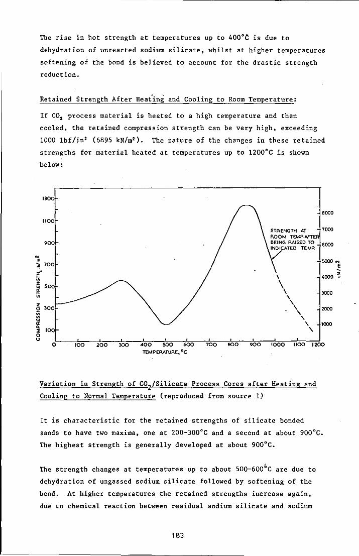
..
The rise in hot strength at temperatures up to 400°C is due to
dehydration of unreacted sodium silicate, whilst at higher temperatures
softening of the bond is believed to account for the drastic strength
reduction.
Retained Strength After Heat"ing and Cooling to Room Temperature:
If CO2 process material is heated to a high temperature and then
cooled, the retained compression strength can be very high, exceeding
1000 Ibf/in2 (6895 kN/m2 ). The nature of the changes in these retained
strengths for material heated at temperatures up to 1200°C is shown
below:
1300
8000
1100
STAENGTH AT 7000 ROOM TEMP..6FTER
900 BEING RAISED TO 6000 INDICATED TEMP.
• i 700
5000 N
E x-l; \ 4000 ~ z
S tu
I!: \ \
\ 3000 UI \
z 300 0
;;;
\ \ 2000
\ on ... et 0.
100 ::E
, \ 1000 ,
0 u
0 100 200 300 400 soo 600 700 BOO 900 1000 1100 1200
TEMPERATURE .. °c
Variation in Strength of COZ/Silicate Process Cores after Heating and
Cooling to Normal Temperature (reproduced from source 1)
It is characteristic for the retained strengths of silicate bonded
sands to have two maxima, one at 200-300°C and a second at about 900°C.
The highest strength is generally developed at about 900°C.
The strength changes at temperatures up to about 500-600°C are due to
dehydration of ungassed sodium silicate followed by softening of the
bond. At higher temperatures the retained strengths increase again,
due to chemical reaction between residual sodium silicate and sodium
1 B3
compounds with grains of quartz sand. In this manner a continuous
monolithic structure of high strength is formed as the temperature is
raised from 600-900°C.
At higher temperatures the quartz form of silica transforms to
tridymite and/or cristobalite." This transformation is accompanied by
a large volume increase, which can be as high as 30-40%, and the
stresses produced lower the retained strength. In cases where the
phase transformation is complete, the specific gravity is reduced from
2.65 to 2.32. The transformation is not reversible to quartz on
cooling in these circumstances.
The magnitude of retained strength is affected by the following process
variables: duration of CO2 gassing; concentration of sodium silicate in
a mixture; the Si02 :Na2 0 ratio of the silicate binder; and organic or
inorganic additions to the sand mixture.
Sources of Information
1 The CO2/Silicate Process in Foundries. K E L Nicholas. BClRA, 1972.
2 Srinagesh K; Int Cast Metals J, 1979, V4, nI, p 50-63.
184
APPENDIX THREE
MOULD MATERIAL TESTS
Specimen Preparation
The tests for permeability, compression strength, tensile strength and
dimensional stability were carried out using standard American
Foundrymen Society (AFS) specimen sizes.
Facing Material:
The preparation of specimens of facing material differed from the
recommended AFS procedures because compaction was unnecessary. The
equipment for the production of compression strength specimens and dog
bone tensile strength specimens was described in section 4.2.4 and is
shown in Figures Six, Seven and Eight. The pouring plates ensured that
the specimens were produced to the correct height. In the case of the
compression strength specimens, it was necessary to carefully remove
the pouring pip from the surface.
Backing Material:
The standard compression strength specimens were prepared by first
weighing out a quantity of the sodium silicate bonded molochite
sufficient to form the specimen. The material was'transferred to a
cylindrical container with a metal base cup. The specimen was next
compacted using the standard procedure to form a specimen of 2" ± 1/32"
(50.8 mm ± 0.79 mm) high. Gassing was carried out immediately after
ramming using a Ridsdale cup for gassing with CO2 • Specimens for as
gassed properties were tested immediately after gassing. Specimens for
fired properties were allowed to cool in the kiln before transfer to a
dessicator. A minimum of three test results were used to establish the
average compression strength.
Tensile specimens were produced using a special moulding box with a
gassing facility, shown in Figure Four. A quantity of material
sufficient to form the specimen was weighed and transferred to the
mould. The specimen was next compacted using the standard procedure
to form a specimen 1" ± 1/64" (25.4 mm ± 0.40 mm) high. The specimen
was gassed whilst remaining in the moulding box. Specimens for as-
1'05
gassed properties were tested immediately after gassing. Those for
fired properties were allowed to cool in the kiln before transfer to a
dessicator. A minimum of three test results were used to establish the
average tensile strength.
Backing/Facing Composites:
By introducing a distance piece into the moulding box and the rammer
head, see Figures Four and Five, the dog bone specimen could be
produced in two halves. Each half was gassed in the mould. The half
backing material sample was then located in one half of the slurry
tensile specimen mould and the mould covered with the slurry pouring
plate. Slurry was poured into the vacant half of the tensile mould and
allowed to gel. After gelation the composite specimen was ignited and
fired to temperature. After cooling in the kiln, the specimens were
stored in a dessicator prior to testing. A minimum of three test
results were used to establish the average· interface tensile strength.
Dimensional Stability:
To provide information on the dimensional stability of the mould
materials, a simple test was used. The dimensions of compression
strength test pieces were measured before and after firing. Care was
taken to ensure that specimens were tested in the correct order. After
firing the specimens were cooled in the kiln and transferred to a
dessicator before testing. A minimum of five dimensions were measured
on each of three test pieces to establish the average change in length
value.
Permeability
A Ridsdale-Dietert electric permmeter was used to evaluate the
permeability of the facing and backing materials. This permeability
meter employs the orifice method for the rapid determination of
permeability. Air at a constant pressure is applied to an AFS standard
specimen (in a specimen tube) and the drop in pressure is measured on a
pressure gauge, which is calibrated directly in AFS permeability
numbers. Check jets were used to establish that the instrument was
working correctly. A Fischer dry permeability holder was used to hold
and seal the vertical surface of the specimens. A minimum of three
test results were used to establish the average permeability number.
186
High Temperature Tests
The tests for hot strength and un impeded linear expansion were
conducted using the George Fischer High Temperature Testing Accessory,
Type PHT. Backing material specimens were produced using the GF
compacting device and were gassed in the specimen tube before extrac
tion. Facing material specimens were produced using the specially
manufactured mould shown in Figure Ten(v). The specimen dimensions for
these tests are 11 mm diameter x 20 mm high.
Measurement of Unimpeded Linear Expansion:
The test specimen standing on a flat, round silica disc is placed on
the lower silica press rod and raised until the top covering convex
silica disc just touches the upper fixed silica press rod. The
position of the pointer on the dial gauge is noted. Subsequently, the
preheated furnace is lowered and the expansion of the test specimen is
continuously noted from the dial gauge. Either the maximum expansion
is noted, or the expansion in relation to time at different temperatures
is determined. For standard tests it is sufficient to determine the
maximum expansion in per cent at 1000°C. A minimum of three test
results were used to establish the average linear expansion value.
Determination of Hot Strength:
The initial procedure for the test is similar to that described above.
The preheated furnace is lowered and the time measured from this moment
on. After a period of time, determined from a reference graph of
heating time vs furnace (or test) temperature, the compression strength
is tested and read from the scale. For the standard test temperature
of 1000°C the specimen must be heated for exactly one minute before
testing for compression strength. A minimum of three test results were
used to establish the average hot strength.
Hot Distortion Test:
The hot distortion test is designed to assess the expansion,
susceptibility to cracking, deformation and bending of bonded sands at
high temperatures. The BClRA Hot Distortion Tester uses a test piece
of 1" x 4.5" x 0.25" (25 mm x 114 mm x 6 mm). This test piece, clamped
at one end and loaded in cantilever, is heated strongly under controlled
conditions at the centre of the underface. A displacement transducer
187
connected to an XY recorder produces a record of movement of the test
piece with time. Interpretation of these records enables the hot
properties of the material to be assessed.
The specimen mould permits sodium silicate bonded material to be blown
using a core blower. The specimen can be gassed in situ. Facing
slurry can be poured into the mould and separated for torching and
firing.
Gas Evolution:
A BClRA-Ridsda1e gas determination apparatus was used to determine the
amount of gas evolved from the backing and facing mould materials. The
test consists of heating a one gramme sample of the mould material in a
pressure tight tube furnace containing a nitrogen atmosphere. As gas
is evolved from the sample it causes an increase in pressure and this
can be recorded against time on a chart recorder. The pressure, in mm
water gauge, can be converted to a gas volume, m1/gm, using calibration
curves. Calibration curves are prepared for the test temperature using ca.rbOf\o..\:.e
pOro.SSiLLt>1 h~dro3eo" (l<H C03 ) which decomposes on heating to release
22.4 litres of gas/mole (100.12 gm).
Sources of Information
1 Methods of Testing Prepared Foundry Sands. Third Report of the
Joint Committee on Sand Testing. Published by the Institute of
British Foundrymen, September 1966.
2 Methods of Testing Cold Setting Chemically Bonded Sands. First
Report of the Joint Committee on Sand Testing (1973). The British
Foundryman, 1976, 69, 9, p 213-221.
3 High Temperature Testing Accessory Type PHT. George Fischer Ltd.
4 Routine Test Procedures on Chemically Bonded Sands - Determination
of Gas Evolution. BClRA Broadsheet 16-16.
5 Hot Distortion Test for Chemically Bonded Sands. BCIRA Broadsheet
177.
188
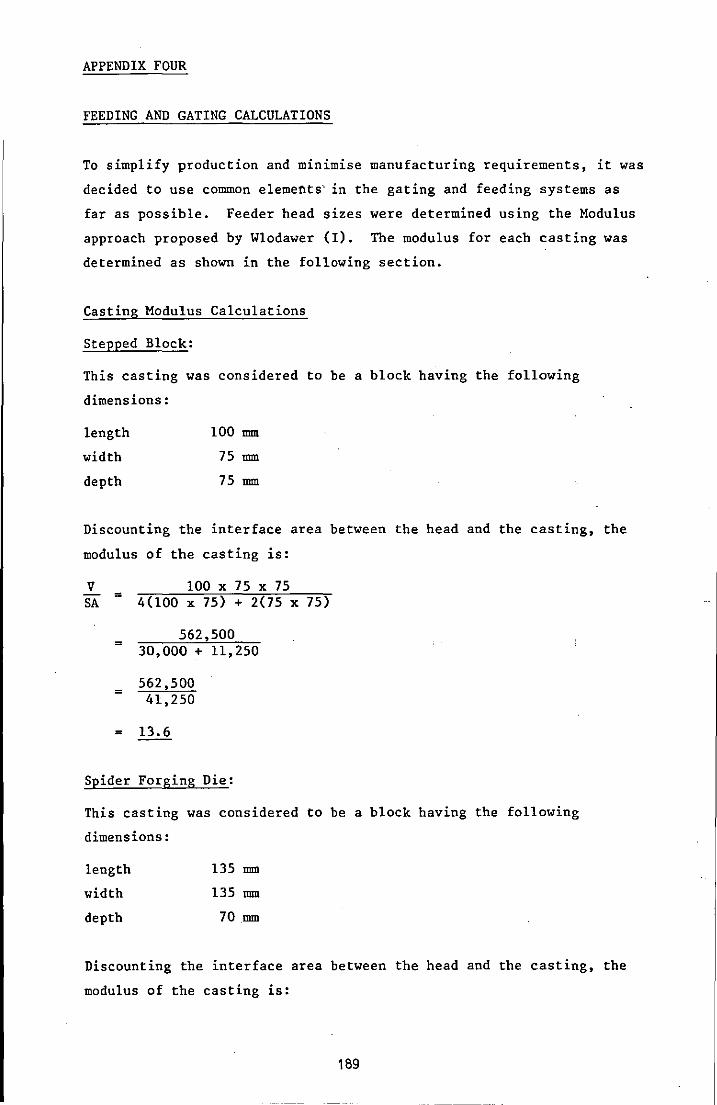
APPENDIX FOUR
FEEDING AND GATING CALCULATIONS
To simplify production and minimise manufacturing requirements, it was
decided to use common elements' in the gating and feeding systems as
far as possible. Feeder head sizes were determined using the Modulus
approach proposed by W10dawer (I). The modulus for each casting was
determined as shown in the following section.
Casting Modulus Calculations
Stepped Block:
This casting was considered to be a block having the following
dimensions:
length
width
depth
100 mm
75 mm
75 mm
Discounting the interface area between the head and the casting, the
modulus of the casting is:
V SA =
=
=
=
100 x 75 x 75 4(100 x 75) + 2(75 x 75)
562,500 30,000 + 11,250
562,500 41,250
13.6
Spider Forging Die:
This casting was considered to be a block having the following
dimensions:
length
width
depth
135 mm
135 mm
70 mm
Discounting the interface area between the head and the casting, the
modulus of the casting is:
189
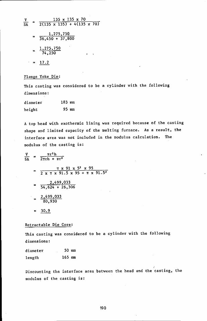
V 135 x 135 x 70 = 2(135 x 135) + 4(135 x 70) SA
= 1,275,750
36,450 + 37,800
= 1,275,750
74,250
= 17.2
Flange Yoke Die:
This casting was considered to be a cylinder with the following
dimensions:
diameter
height
183 mm
95 mm
A top head with exothermic lining was required because of the casting
shape and limited capacity of the melting furnace. As a result, the
interface area was not included in the modulus calculation. The
modulus of the casting is:
V SA =
1Ir2h 211rh + 1Ir2
11 x 91 X 52 X 95 = 2 x 11 x 91.5 x 95 + 11 x 91.52
=
=
=
2,499,033 54,624 + 26,306
2,499,033 80,930
30.9
Retractable Die Core:
This casting was considered to be a cylinder with the following
dimensions:
diameter
length
50 mm
165 mm
Discounting the interface area between the head and the casting, the
modulus of the casting is:
190
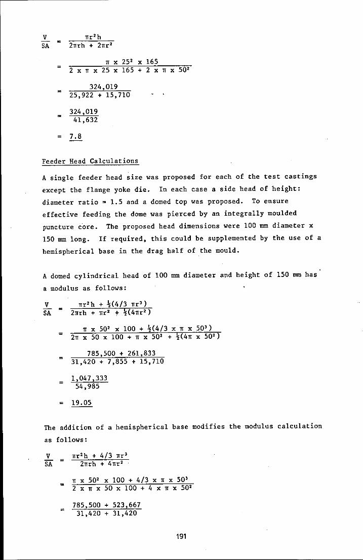
V SA =
=
=
=
=
lTr'h 2lTrh + 2lTr'
IT X 25' x 165 2 x IT x 25 x 165 + 2 x IT X 50'
324,019 25,922 + 15,710
324,019 41,632
7.8
Feeder Head Calculations
A single feeder head size was proposed for each of the test castings
except the flange yoke die. In each case a side head of height:
diameter ratio = 1.5 and a domed top was proposed. To ensure
effective feeding the dome was pierced by an integrally moulded
puncture core. The proposed head dimensions were 100 mm diameter x
150 mm long. If required, this could be supplemented by the use of a
hemispherical base in the drag half of the mould.
A domed cylindrical head of 100 mm diameter and height of 150 mm has
a modulus as follows:
V SA
=
=
=
=
=
lTr'h + %(4/3 lTr 3 )
2lTrh + lTr' + %(4lTr')
IT X 50' x 100 + %(4/3 x IT x 503 )
2lT x 50 x 100 + IT X 50' + %(4lT X 50')
785,500 + 261,833 31,420 + 7,855 + 15,710
1,047,333 54,985
19.05
The addition of a hemispherical base modifies the modulus calculation
as follows:
V SA =
=
=
lTr'h + 4/3 lTr 3
2lTrh + 4lTr'
IT X 50' x 100 + 4/3 x IT x 503
2 x IT x 50 x 100 + 4 x IT X 50'
785,500 + 523,667 31,420 + 31,420
191

=
=
1,309,167 62,840
20.8
According to Wlodawer, the modulus of the head should be at least.
1.2 x the modulus of the ca~ti~g, to ensure that the head solidifies
after the casting.
For the stepped block:
Mh > 1.2 Mc
> 1.2 x 13.6 = 16.3
this condition is met by the domed head.
For the spider forging die:
Mh > 1.2 Mc
> 1.2 x 17.2 = 20.6
this condition is met by the domed head with a hemispherical base.
For the retractable die core:
Mh > 1.2 Mc
> 1.2 x 7.8 = 9.4
this condition is met by the domed head.
Flange Yoke Die:
For this casting a top head of 150 mm diameter and 150 mm high was
proposed. A Foseco Kalminex exothermic sleeve was used. The nominal
modulus of such a head is:
V SA =
=
=
=
=
11r 2h 211rh + 11r2
11 X 752 x 150 211 x 75 x 150 + 11 x 752
2,651,063 70,695 + 17,674
2,651,063 88,369
30
192

The sleeve extends the modulus by a factor of 1.3,
modulus of the head is 39.
the true
The modulus of the flange yoke die was calculated as 30.9. For the
head to be effective:
Mh > 1.2 Mc
> 1.2 x 30.9 = 37.1
this condition is met by the Foseco sleeved head.
Although the modulus approach produces a feeder head which stays
liquid longer than the casting, two further checks are required to
ensure that the head sizes calculated are suitable. These are for
volume feed capacity and feeding distance.
Volume Feed Capacity
For plain cylindrical heads:
V max (casting) = 14 - S
V head x S
where S = specific shrinkage of the alloy (%).
For a head lined with exothermic material this expression becomes:
V max (casting) = 67 - S
V 1; e ad x =---"S----'::'
The specific shrinkage for H13 was assumed to be 5%, in the absence
of an available reference source.
The volume of each of the four castings was calculated to be:
(i) stepped block 562,500 mm'
(H) spider forging die 1,275,750 mm'
(Hi) flange yoke die 2,499,033 mm'
(iv) retractable die core 324,019 mm'
Now, taking only the ~100 mm x 100 mm high section of the proposed
head:
V max (casting) = 14 - 5
785,500 x 5
= 32,873,181 mm'
.'. the head has sufficient volume feed capacity for castings (i) to
(Hi) above. 193

Feeding Distance
Applying the feeding distance rules developed by Pellini (11):
For a bar the feeding distance is 6/T.
For a plate the feeding distance is 4.5T.
(where T is given in inches)-
For each of the castings:
(i) stepped block T max = 75
(H) spider forging die T max = 70
mm
mm
(Hi) flange yoke die (not applicable)
(iv) retractable die core
For (i), feeding distance
T max = 50 mm
= 6/75/25.4
= 262 mm
as the casting is 100 mm long, this is more than adequate.
For (ii), feeding distance = 4.5 x (70/25.4)
= 315 mm
as the casting is 135 mm long, this is more than adequate.
For (iii), feeding distance = 6/50/25.4
= 214 mm
as the casting is 165 mm long, this is adequat~.
Gating Systems
The dimensions of a gating system are usually described in terms of the
gating ratio a:b:c, where:
a = cross-sectional area of the sprue
B = cross-sectional area of the runner
c = cross-sectional area of the ingate
The recommendations for dimensioning gating systems contained in the
literature are diverse. However, in a paper on premium quality casting
production, Polich et al (Ill) recommend a ratio of 1:2:2 for steel
castings and this proposal has been adopted.
194
For the stepped block, spider die and die core castings, a side head
was used. For such a layout, Wa11ace (IV) recommends minimum size
dimensions for the neck connecting the head and casting. To minimise
the tendency for premature solidification in the neck, the dimension
of Ln should not exceed 15 mm. A Washburn core was used with the
stepped block casting, whereas'mou1ded gates were used for the spider
die and the die core.
The arrangement for the flange yoke die casting required gating into
the mould cavity from the runner bar and the use of a top head. The
arrangement for the other three castings involved running the metal
into the head before filling the mould cavity.
With'Ln set at 15 mm:
On = 1.2 x 15 + 0.1 x 100
= 0 28 mm
cross-sectional area of ingate ~ 600 mm'.
On this basis, the gating ratio becomes:
300:600:600
The runner bar dimensions to provide this cross-sectional area are:
height
width
25 mm
25 mm (base)
23 mm (top)
The sprue outlet diameter to provide a cross-sectional , area of 300 mm'
is 20 mm. To avoid aspiration a tapered sprue is advised, the
dimensions of which can be determined from the expression:
Ao Ai =
sprue inlet area is:
Ai Ao =
175/250
= 545 mm'
and the sprue inlet diameter is 26 mm.
195

To minimise turbulence effects at the base of the sprue, it is
recommended that a sprue well be incorporated in the gating system.
To meet this requirement, a sprue well diameter of 50 mm was u·sed.
As indicated previously, the stepped block was gated using a 0 28 mm
ingate produced using a Washoutn core. This permitted gating at the
centre of the heaviest section. For the other castings it was
necessary touse different ingate shapes, although the ingate area
remained constant.
Retractable Die Core:
Although this component is moulded in both the cope and drag, its
design is such that an ingate can only be accommodated in the cope.
A semicircular ingate with a radius of 20 mm was chosen.
Spider Forging Die:
As the casting is moulded in the cope, the ingate must also be moulded
in the cope. In the interest of commonality, the ingate for the
retractable die core was used;
Flange Yoke:
A simple tangential runner bar with a rectangular ingate blended into
the casting diameter yas used.
Pouring Times
The pouring times for each of the casting configurations can be
calculated using the following formula (V):
t = W
d.C.A. !2g.H
where:
t = pouring time (in seconds)
w = casting weight (in kg)
d = density of metal (in kg/m')
C = discharge coefficient for system
A = choke area (in m2)
G = acceleration due to gravity (9.81 ms)
H = effective height of metal head (metres)
196
The value of C has been quoted as 0.5 to 0.9 in the literature. For
this calculation an average value of 0.7 was used. The density of the
alloy is 6800 kg/m' and the value of H is 0.275 m.
For the purpose of calculations the estimated weight of metal cast,
which includes gating and fe·eding systems, for each casting is:
(i) stepped block 13.4 kg
( H) spider forging die 21.5 kg
(Hi) flange yoke die 28.1 kg
(iv) retractable die core 12.2 kg
The value of d.C.A. 12g.H is a constant for these castings and is
equal to:
6800 x 0.7 x 3.142 x 10- 4 12 x 9.81 x 0.275
= 3.46
t
~ouring time for each casting:
(i) t 13.4 3.9 seconds = = 3.46
(H) 21.5 6.2 seconds t = = 3.46
(Hi) 28.1 8.1 seconds t = = 3.46
(iv) 12.2 3.5 seconds t = 3.46 =
References for Appendix Four
I Wlodawer R; Directional Solidification of Steel Castings,
Pergammon Press, Oxford, 1966.
11 Pellini W S; Trans AFS, 1953, 61, 61.
III Polich R F, Saunders A and Flemings MC; Trans AFS,· 1963, 71, 418.
IV Wallace J F (Editor); Fundamentals of Risering Steel Castings,
Steel Founders Society, USA, 1960.
V Report of IBF Subcommittee TS24, Foundry Trade J, 1955, 99, 691.
197
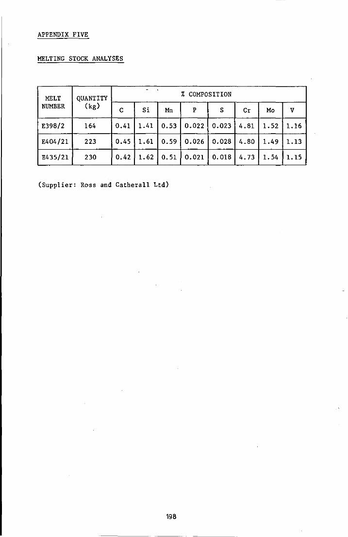
APPENDIX FIVE
MELTING STOCK ANALYSES
. MELT QUANTITY % COMPOSITION
NUMBER (kg) C Si Mn P S Cr Mo V
E39S/2 164 0.41 1.41 0.53 0.022 0.023 4.S1 1.52 1.16
E404/21 223 0.45 1.61 0.59 0.026 0.02S 4.S0 1.49 1.13
E435/21 230 0.42 1.62 0.51 0.021 O.OlS 4.73 1.54 1.15
(Supplier: Ross and Catherall Ltd)
19S
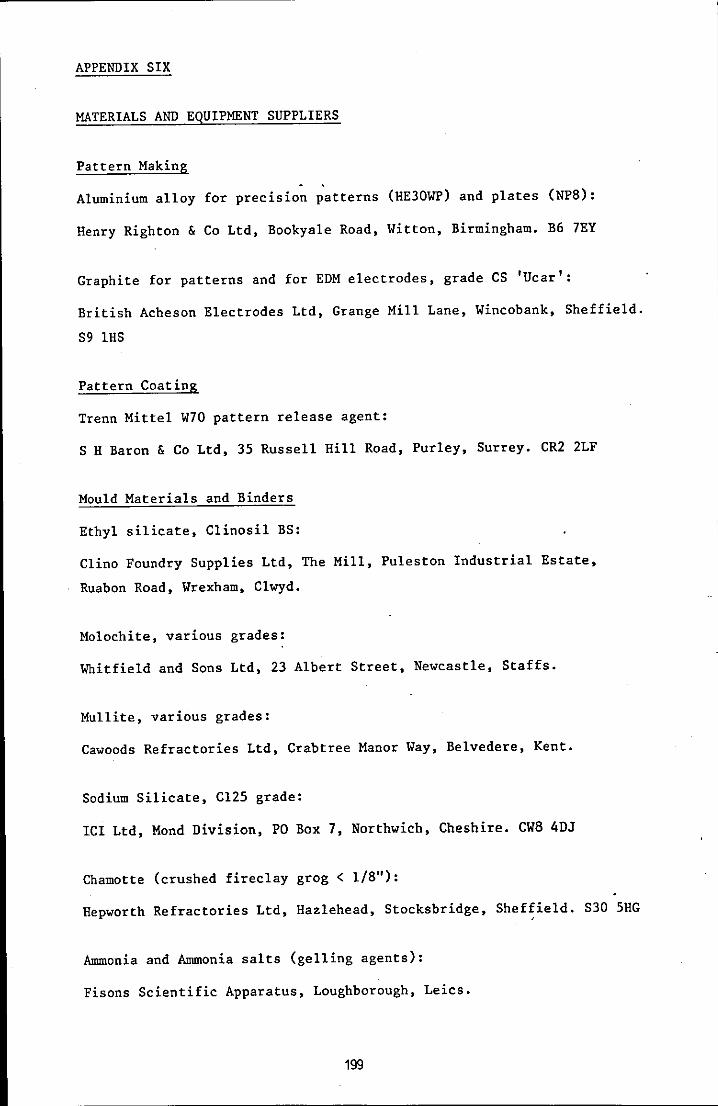
APPENDIX SIX
MATERIALS AND EQUIPMENT SUPPLIERS
Pattern Making
Aluminium alloy for precision patterns (HE30WP) and plates (NPB):
Henry Righton & Co Ltd, Bookyale Road, Witton, Birmingham. B6 7EY
Graphite for patterns and for EDM electrodes, grade CS 'Ucar':
British Acheson Electrodes Ltd, Grange Mill Lane, Wincobank, Sheffield.
S9 IHS
Pattern Coating
Trenn Mittel W70 pattern release agent:
S H Baron & Co Ltd, 35 Russell Hill Road, Purley, Surrey. CR2 2LF
Mould Materials and Binders
Ethyl silicate, Clinosil BS:
Clino Foundry Supplies Ltd, The Mill, Puleston Industrial Estate,
Ruabon Road, Wrexham, Clwyd.
Molochite, various grades:
Whitfield and Sons Ltd, 23 Albert Street, Newcastle, Staffs.
Mullite, various grades:
Cawoods Refractories Ltd, Crabtree Manor Way, Belvedere, Kent.
Sodium Silicate, C125 grade:
ICI Ltd, Mond Division, PO Box 7, Northwich, Cheshire. CW8 4DJ
Chamotte (crushed fireclay grog < l/B"):
Hepworth Refractories Ltd, Hazlehead, Stocksbridge, Sheffield. S30 5HG
Ammonia and Ammonia salts (gelling agents):
Fisons Scientific Apparatus, Loughborough, Leics.
1~
Sairset (mould jointing compound):
Wm E11iot and Sons Ltd, 155 G1aisda1e Drive West, Nottingham.
Mo1dcote 33:
Foseco (FS) Ltd, Dray ton Manor, Tamworth, Staffs.
Graphite (- 100 mesh grade):
S & A B1ackwe11 (St Annes) Ltd, 10 Market Square, Lytham, Lytham
St Annes.
Melting Stock
BS 4659 : 1971 BR 13 die steel:
Ross and Cathera11 Ltd, Forge Lane, Ki11amarsh, Nr Sheffield. S31 8BA
Melt Treatment
Crucibles and shanking ladle:
Refractory Mouldings and Castings Ltd, Market Place, Kegworth, Derby.
DE7 2EF
Slax 30 slag coagulant and Ste11agen 1 deoxidiser:
Foseco (FS) Ltd
Ferro alloys - various:
S & A B1ackwe11 (St Annes) Ltd
Feeding Aids
Exothermic sleeves (6" ID) with and without breaker cores:
Foseco (FS) Ltd
Special Equipment
Spermo1in mixer (50 1b capacity):
Newport Forge and Engineering Ltd, Pantg1as Estate, Bedwas, Gwent.
200

Bricesco Electrikiln, model SK/705:
British Ceramic Service Co Ltd, Bricesco House, Park Avenue,
Wolstanton, Newcastle, Staffs. ST5 BAT
Digital meter stick:
Leeds and Northrup Ltd, Wharfedale Road, Tyseley, Birmingham. BII 2DJ
Heat resisting mould firing trays:
Wel1man Alloys Ltd, Amb1ecote, Stourbridge, West Midlands. DYB 4HW
Air motor and fittings:
Airtoo1s and Compressors Ltd, Leicester Depot, 102 Catherine Street,
Leicester.
Special toggle clamp fittings for mould stripper:
D H Woo11ey (Quorn) Ltd, Unit 2, Windmill Road, Loughborough, Leics.
Oxy-propane burner for mould torching and pouring shank preheating:
Z Onions & Sons, Station Avenue, Loughborough. LE11 OEB
Copper tube for induction heating coil (Enots 5/16" OD x 20 g):
Thos P Headlands, 60 Cannock Street, Barkby Thorpe Road Industrial
Estate, Leicester.
201
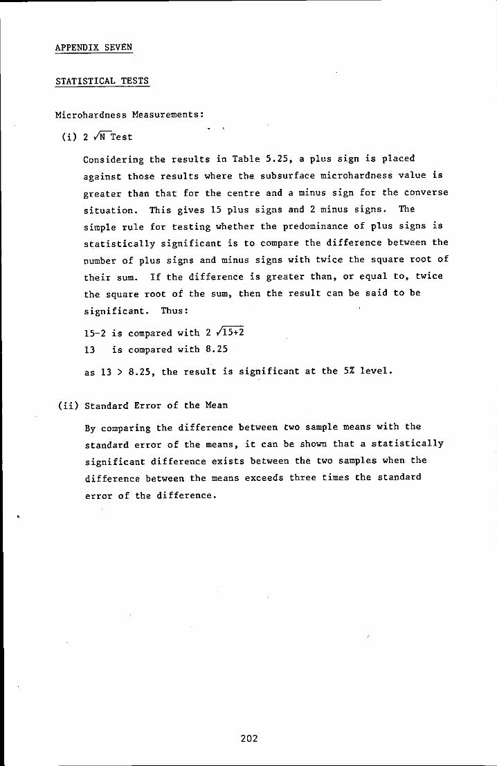
APPENDIX SEVEN
STATISTICAL TESTS
Microhardness Measurements:
(i) 2 ~Test
Considering the results in Table 5.25, a plus sign is placed
against those results where the subsurface microhardness value is
greater than that for the centre and a minus sign for the converse
situation. This gives 15 plus signs and 2 minus signs. The
simple rule for testing whether the predominance of plus signs is
statistically significant is to compare the difference between the
number of plus signs and minus signs with twice the square root of
their sum. If the difference is greater than, or equal to, twice
the square root of the sum, then the result can be said to be
significant. Thus:
15-2 is compared with 2 /15+2
13 is compared with 8.25
as 13 > 8.25, the result is significant at the 5% level.
(ii) Standard Error of the Mean
By comparing the difference between two sample means with the
standard error of the means, it can be shown that a statistically
significant difference exists between the two samples when the
difference between the means exceeds three times the standard
error of the difference.
202
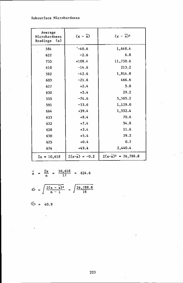
Subsurface Microhardness
Average x) Microhardness (x -Readings (x)
584 --40.6
622 -2.6
733 +108.4
610 -14.6
582 -42.6
603 -21.6
627 +2.4
630 +5.4
550 -74.6
591 -33.6
664 +39.4
633 +8.4
632 +7.4
628 +3.4
630 +5.4
625 +0.4
674 +49.4
l:x = 10,618 l:(x-~) = -0.2
l:x 10,618 624.6 = x = n 17
6 = J l:(x - X)2 n - 1
<0 = 40.9
= /26,788.8 16
203
(x - x)2
1,648.4
6.8
11,750.6
213.2
1,814.8
466.6
5.8
29.2
5,565.2
1,129.0
1,552.4
70.6
54.8
11.6
29.2
0.2
2,440.4
l:(X_~)2 = 26,788.8

Centre Microhardness
Average" Microhardness (x - ~) (x - ~)2
Readings (x)
649 --36.9 1,361.6
636 -49.9 2,490.0
727 +41.1 1,689.2
683 -2.9 8.4
763 +77 .1 5,944.4
684 -1.9 3.6
698 +12.1 146.4
695 +9.1 . 82.8
651 -34.9 1,218.0
687 +1.1 1.2
651 -34.9 1,218.0
713 +27.1 734.4
673 -12.9 166.4
675 -10.9 118.8
675 -10.9 118.8
658 -27.9 778.4
742 +56.1 3,147.2
LX = 11,660 E(x-~) = -0.3 l:(x-~)2 = 19,227.6
Ex 11,660 685.9 x = = = n 17
6 = J E(x - ~)2 19,227.6 n - 1 16
6 34.7
The standard error of the means is given by 6/10:
for subsurface = 40.9/117 = 10
for centre = 34.7/117 = 8.5
The standard error of the difference between the means of the two
samples is:
/[(10)2 + (8.5)2] = /[172.3] = 13.1
204

The difference between the means is 685.9 - 624.6 = 61.3, which
is more than three times the standard error of the difference.
The difference is statistically significant at the 5% level.
Grain Size Measurements:
(i) Tukey Test
This test is more flexible than the 2 ~test because it may be
used where there are unequal numbers in the two groups. Let A be
the group without grain refining additions and B the group with
grain refining additions, see Table 5.26. For group A the highest
value is 4.7 and the lowest value is 2.7. For group B the highest
value is 6.0 and the lowest value is 4.3. The number of values in
the B group which are higher than the highest value in the A group
is 12 and the number of values in the A group which are lower than
the lowest value in the B group is 8. Adding these two numbers
gives a score of 20. If the score is equal to, or greater than,
7 the difference is significant. As 20 is greater than 7 the
difference is significant at the 5% level.
(ii) Standard Error of the Mean
Applying the more discriminating test to the data:
without grain refining additions:
Average (x - ;;) Number of Grains (x - ;;) 2
Intercepted (x)
4.7 -1.0 1.0
2.7 +1.0 1.0
3.3 +0.4 0.16
3.3 +0.4 0.16
3.7 0 0
4.7 -1.0 1.0
3.7 0 0
4.0 -0.3 0.09
3.0 +0.7 0.49 ,
3.7 0 0
LX = 36.8 E(x-;;) = +0.2 E(x-;;)2 = 3.9
205

Ex 36.8 3.7 x = = = n 10
6 jE(: - ;;:)2 j 399 = = - 1
6 = 0.66
with grain refining additions:
Average (x - ;;:) Number of Grains (x - ;;:)2
Intercepted (x)
4.7 +0.7 0.49
6.0 -0.6 0.36
5.3 +0.1 0.01
5.0 +0.4 0.16
6.0 -0.6 0.36
5.7 -0.3 0.09
6.0 -0.6 0.36
5.3 +0.1 0.01
5.0 +0.4 0.16
4.7 +0.7 0.49
4.3 +1.1 1.21
5.3 +0.1 0.01
5.7 -0.3 0.09
5.7 -0.3 0.09
5.7 -0.3 0.09
Ex = 80.4 E(x-;;:) = +0.6 E(x-;;:)2 = 3.98
Ex 80.4 5.4 x = = = n 15
cS j E(x - ;;:)2 = j 3.98 = n - 1 14
<5 = 0.53
The standard error of the means is:
without grain refining additions = 0.66//10 = 0.21
with grain refining additions = 9.53/1iS· = 0.14
206
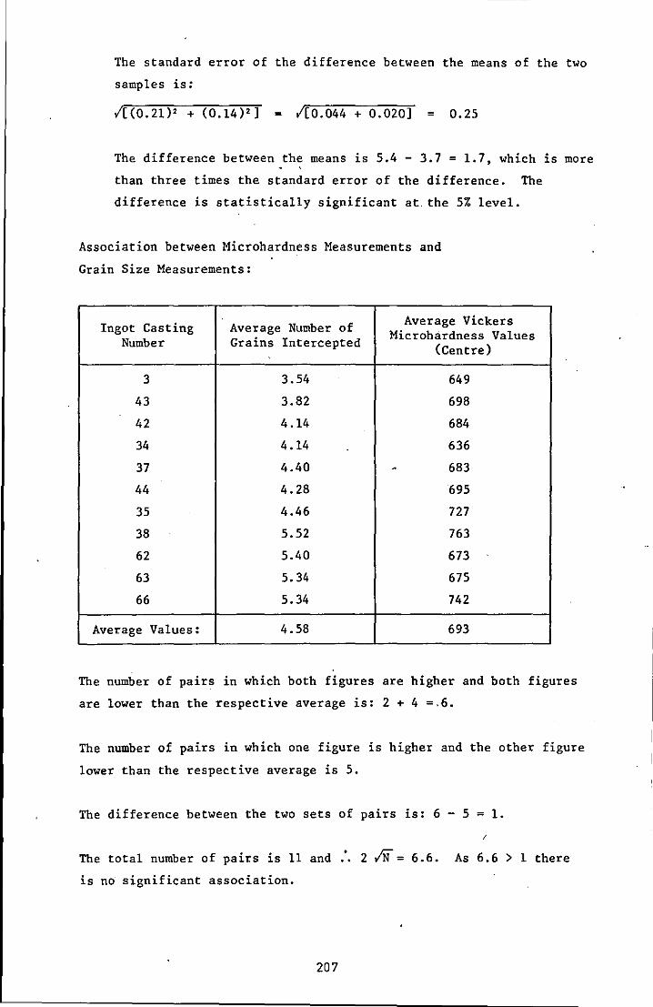
The standard error of the difference between the means of the two
samples is:
1[(0.21)2 + (0.14)2] = 1[0.044 + 0.020] = 0.25
The difference between the means is 5.4 - 3.7 = 1.7, which is more
than three times the standard error of the difference. The
difference is statistically significant at. the 5% level.
Association between Microhardness Measurements and
Grain Size Measurements:
Ingot Casting Average Number of Average Vickers Microhardness Values Number Grains Intercepted (Centre)
3 3.54 649
43 3.82 698
42 4.14 684
34 4.14 636
37 4.40 . 683
44 4.28 695
35 4.46 727
38 5.52 763
62 5.40 673
63 5.34 675
66 5.34 742
Average Values: 4.58 693
The number of pairs in which both figures are higher and both figures
are lower than the respective average is: 2 + 4 =.6.
The number of pairs in which one figure is higher and the other figure
lower than the respective average is 5.
The difference between the two sets of pairs is: 6 - 5 = 1.
The total number of pairs is 11 and
is no significant association.
207
/
2 IN = 6.6. As 6.6 > 1 there
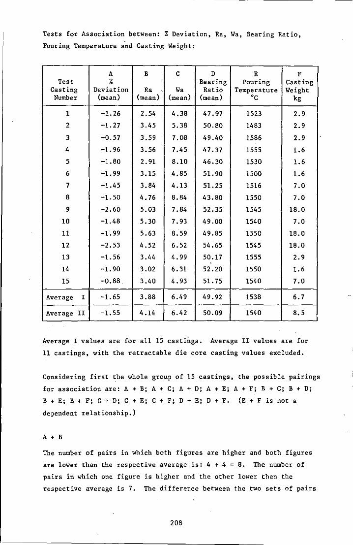
Tests for Association between: % Deviation, Ra, Wa, Bearing Ratio,
Pouring Temperature and Casting Weight:
A B C D E F Test % Bearing Pouring Casting
Casting Deviation Ra Wa Ratio Temperature Weight Number (mean) (mean) (mean) (mean) °c kg
1 -1.26 2.54 4.38 47.97 1523 2.9
2 -1.27 3.45 5.38 50.80 1483 2.9
3 -0.57 3.59 7.08 49.40 1586 2.9
4 -1.96 3.56 7.45 47.37 1555 1.6
5 -1.80 2.91 8.10 46.30 1530 1.6
6 -1.99 3.15 4.85 51.90 1500 1.6
7 -1.45 3.84 4.13 51.25 1516 7.0
8 -1.50 4.76 8.84 43.80 1550 7.0
9 -2.60 5.03 7.84 52.35 1545 18.0
10 -1.48 5.30 7.93 49.00 1540 7.0
11 -1.99 5.63 8.59 49.85 1550 18.0
12 -2.53 4.52 6.52 54.65 1545 18.0
13 -1.56 3.44 4.99 50.17 1555 2.9 . 14 -1.90 3.02 6.31 52.20 1550 1.6
15 -0.88. 3.40 4.93 51.75 1540 7.0
Average I -1.65 3.88 6.49 49.92 1538 6.7
Average II -1.55 4.14 6.42 50.09 1540 8.5
Average I values are for all 15 castings. Average 11 values are for
11 castings, with the retractable die core casting values excluded.
.
Considering first the whole group of 15 castings, the possible pairings
for association are: A + B; A + C; A + D; A + E; A + F; B + C; B + D;
B + E; B + F; C + D; C + E; C + F; D + E; D + F. (E + F is not a
dependent relationship.)
A + B
The number of pairs in which both figures are higher and both figures
are lower than the respective average is: 4 + 4 = 8. The number of
pairs in which one figure is higher and the other lower than the
respective average is 7. The difference between the two sets of pairs
208
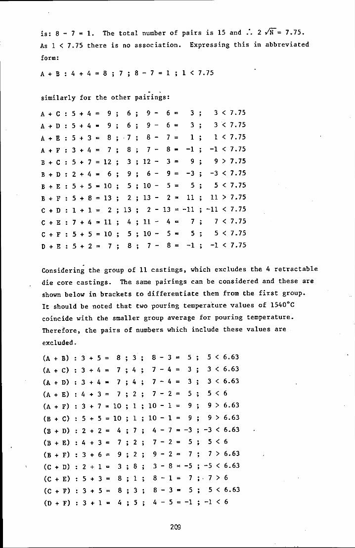
is: 8 - 7 = 1. The total number of pairs 1S 15 and :. 21N= 7.75.
As 1 < 7.75 there is no association. Expressing this in abbreviated
form:
A + B 4 + 4 = 8 7 8 - 7 = 1 1 < 7.75
similarly for the other pairings:
A + C
A + D
A + E
A + F
B + C
B + D
B + E
B + F
C + D
C + E
C + F
D + E
5 + 4 = 9
5 + 4 = 9
5 + 3 = 8
3 + 4 = 7
5 + 7 = 12
2 + 4 = 6
5 + 5 = 10
5 + 8 = 13
1 + 1 = 2
7+4=11
5 + 5 = 10
5 + 2 = 7
.
6
6
7
8
3
9
5
2
13
4
5
8
9 - 6 =
9 - 6 =
8 - 7 =
7 -
12 -
6 -
10 -
13-
2 -
11-
10 -
7 -
8 = 3 =
9 =
5 =
2 =
13=
4 =
5 =
8 =
3
3
1
-1
9 ;
-3
5
11
-11
7 ;
5 ;
-1
3 < 7.75
3 < 7.75
1 < 7.75
-1 < 7.75
9 > 7.75
-3 < 7.75
5 < 7.75
11 > 7.75
-11 < 7.75
7 < 7.75
5 < 7.75
-1 < 7.75
Considering the group of 11 castings, which excludes the 4 retractable
die core castings. The same pairings can be considered and these are
shown below in brackets to differentiate them from the first group.
It should be noted that two pouring temperature values of 1540°C
coincide with the smaller group average for pouring temperature.
Therefore, the pairs of numbers which include these values are
excluded.
(A + B)
(A + C)
(A + D)
(A + E)
(A + F)
(B + C)
(B + D)
(B + E)
(B + F)
(C + D)
(C + E)
(C + F)
(D + F)
3 + 5 = 8 3
3+4= 7;4
3+4= 7 4
4+3= 7 2
3 + 7 = 10 1
5 + 5 = 10 1
2+2= 4 7
4 + 3 = 7 2
3 + 6 = 2 + 1 =
5 + 3 =
3 + 5 = 3 + 1 =
9 2
3 8
8 1
8 ; 3
4 5
8 3 = 5; 5 < 6.63
7 - 4 = 3
7 - 4 = 3
7 - 2 = 5
10 - 1 = 9
10 - 1 = 9
4 - 7 = -3
7 - 2 = 5
3 < 6.63
3 < 6.63
5 < 6
9 > 6.63
9 > 6.63
-3 < 6.63
5 < 6
9 - 2 = 7; 7 > 6.63
3 - 8 = -5 -5 < 6.63
8 - 1 = 7;. 7 > 6
8 - 3 = 5 5 < 6.63
4 - 5 = -1 -1 < 6
209

A statistically significant association at the 5% level exists for the
following pairs:
Group I
Group II
B + C and B + F
A + F ; B + C B + F and C + E
210
APPENDIX EIGHT
RELATED PUBLICATIONS
The following publications have arisen from the project described in
this thesis and copies of thl' p.apers are presented:
1 Precision Casting for Moulds and Dies. A J Clegg and A A Das, The
Production Engineer, 1978, 57, 11, p 17-21.
2 Precision Cast Tooling. A J Clegg and A A Das, paper presented to
the Engineers' Digest International Conference entitled: New
Frontiers in Tool Materials, Cutting Techniques and Metal Forming,
London, 1979, 15-16 March, pp 18.
3 The Shaw Process - A Review. A J Clegg, Foundry Trade Journal,
1980, 149, 3197, p 429-438 and reprinted in Foundry Technology- A
Source Book, edited by P J Mikelonis and published by the American
Society for Metals, 1982, Ohio, p 53-58.
211
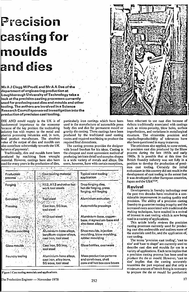
Precision asting for ~oulds
nddies MrAJ Clegg MIProdE and MrAA Dasofthe department of engineering production at Loughborough University of Technology take a look at the precision casting processes currently used for producing cast dies and moulds and other tooling. The authors are involved in a Science Research Council sponsored investigation into the production of precision cast tooling.
DIE AND mould supply in the UK is of fundamental importance to the economy because of the key position the toolmaking induStry has with respect to the metal and plastics processing industries and, in turn, final product manufacture. The absolute value of the output of dies and moulds can also contribute substantially towards the UK balance of payments I.
Traditionally, dies and moulds have been produced by machining from wrought material. However. castings have also been used for many years in the production of dies,
particularly iron castings which have been used in the manufacture of automobile press body dies and dies for permanent mould or gravity die casting. These castings have been -produced by the traditional sand casting routes and required machiIung to produce the required final dimen~ions.
The casting process provides the designer with broad freedom for his ideas. Casting is the cheapest and most convenient method of producing intricate detail and complex shapes in a wide variety of metals and alloys. Die users, however, have with certain exceptions,
,,'~ -.• : - .: •• ,", . .-} ": ' • ': .. ".; r " •
" Production'!',. co:' ";;Casttooli~g majeri;'!"-' :' Typical cast tooling':,' ;:', procesS·-:.,:.~·::'"o·:.~\;::/ -~,If;B~f\~~":"-~" -. -..-: -:~,-~'~>'-:r, application . - :" =.- ,_:,'.
~~~~~~~~--~~~~~--~ Forging ':, :,,; H 12; H 13and other hOt", Drop'forging dies,
_. '-,' '\"".,"",or1:< tool steels . .., hot die forging. press .. _~ ~', ',~':-.~.~ .. -:.;"';: :':' forging. r,?U forgir:-ag ,
~trusi~;':::~~:~~!k;. ~~:-j~~~~~~~I",,',,-\L :::2~:;" Aluminiuni'ext~si~;! ':Pre~sing: ': ~.~.-> .- . Cast iron, SG iron, Automobile pressings
, tool steel -
Foundry tooling Aluminium-base alloys, cast iron, alloy irons, SG irons, tool steel
Figurt I CaS( tooling mattriab and applications.
he Production Engineer- November 1978
Mass production panerns and coreboxes. shell core and hot box core boxes
212
been reluctant to use cast dies because of defects traditionally associated with castings such as micro-porosity, blow holes. surface imperfections. and variations in metallurgical structure. The obtainable precision and reprducfreproducibility of tolerances have also been questioned in many instances.
The criticisms also applied, to some extent, to precision cast dies produced by the Shaw process during the late 1950s and early 1960s. It is possible that at this time the British foundry industry was not fully in a' position to develop the production of precision cast tooling. Certainly the initial enthusiasm in thie country did not result in the development of cast tooling to the extent that it was developed in other European countrie~ Japan and the USA""'.
Revival Developments in foundry technology over
the past two decades have resulted in a considerable improvement in casting quality and precision. The ability of a precision casting I
foundry to guarantee casting integrity and the increased costs aesociated with traditional die making techniques. have resulted in a revival of interest in cast tooling which is now being used in a variety of applications,
This article briefly reviews the precision casting processes currently used for producing cast dit;s andmoulds and outlines some of the materials used for, and the application of, cast tooling.
The terms £precision cast tooling', £cast to size' and ~cast to shape' are currently used to describe cast dies and moulds for use in a variety of applications. Each term implies that a precision casting process has been used to produce the die or mould. However, 'cast to size" implies that the casting accurately resembles the part required and that only a minimum amount of bench fitting is necessary to prepare the die or mould for production
17

.ISI lesignation
B54659:1971 ~-=~N~om~in~a~l;c~h~e=m~ic~a~l~c~0~m~p~ors~it7io~n~(,%~)~~ designation C W Cr Mc V Co
Remarks
12 BA2 1.00 5.00 1.00 0.20 Air hardening; good balance of abrasion resistance. toughness. and freedom from
2
12
13
19
21
26.
42. '.':
B02',
BHI2 .. :,·
BH13 ::
",,' ,
!lH19
BH21',
BH26
,~ "
...• '." -' ~ . , Y··
'1.50 12.00
0.35 1.50 .5.00
O,~5 5.00
0.40 4.25 4.25
0.35 9.50 3.50
0.50 18.00 4.00
0.80
1.50
1.50
0.90
1.00
1.00
hardening hazards
Excellent haidn'ess and abrasion resistanc'e
General purpose; 9oodbalanceoft~ughn-ess and wear resistance; can be watercooled in service
Better abrasive we~rthan H 12; can be watercooled in service -,
2.00 4.25 Good resistance to hot abrasive wear'
1.00 High speed steei; optimum resistanc~;to ..:ve~r in high temperature f~.rging applications
0.60. '6.00 4.00 5.00 2.00· Maintains high hardness at high (lperating temperatures -' ... :.
~ .-. -.'
re 2 Steels ror cast tooling applications - sce Rderence 7.
'Cast to shape' indicates that the casting ely resembles the required shape of the die ould but the casting incorporates a pre
rmined finishing allowance. . e quality of precision encompasses not the accuracy of individual dimensions
surface finish and general appearanCe'. ideal casting :would not only fall within ified dimensional tolerances but its outwould be crisp and clear cut and its sursmooth. With precision is coupled the
ity of intricacy, seen -in the reproduction aborate reatures and fine detail.
ramic moulding Ithough measures taken by the foundry
ncrease precision can result in increased , increased accuracy may reduce ~the
I costs by the reduction or elimination or hining, particularly where difficult cons, awkward access or tough alloys are lved. The factors which influence ensional accuracy arc:
Accuracy of the pattern and mould ipment
Accuracy with which the mould cavity oduces the pattern shape after pattern drawal
Accuracy with which the casting con, s to the original shape of the mould
ity, depending on the characteristics orthe tal/mould combination and the ensional stability of the mould cavity on
ng The contraction factor, which deter
es the predictability of dimensional
•
changes during' cooling • Finishing operations. The precision casting processes almost
universally adopted in the production of precision cast tooling are the ceramic moulding methods of the Shaw process or its variant the Unicast process. In either process the essential prerequisites to successful precision castings are accurately produced patterns and mould equipment.
It is clear that a casting cannot be more accurate than the pattern rrom which it is produced. The mould material is produced by blending a finely ground refractory powder, usually muUite, v.ith ethyl silicate, a liquid binder. By adding a hydrolysing agent and a catalyst, a colloidal silica gel is formed which binds the refractory grains together.
Rubbery nature Careful selection of the mould material
results in two specific benefits. Firstly, the fine grains of the refractory. mould material produce a very smooth surface finish on the resultant casting. And secondly, the selection or a thermally stable mould material ensures that the mould is not subject to excessive dimensional changes during metal casting thus enabling an accurate prediction or casting contraction factors.
The blended liquid slurry is poured into the moulding box and around the pattern. Within a short period of time, controlled by the amount of catalyst added, the moald material gels to a rubbery consistency and the mould can be removed from the pattern. One of the
Ur( 3 Group ortypical utnlsion and forsing dies,prtcision cast in bot ""orl; tool sttel.
213
advantages or this process is that pouring the liquid slurry over the pattem ensures a high degree of contact and therefare accuracy and intricacy in the final casting. Also, the mould material sets in contact with the pattern and co",equently produces a mould which accurately reproduces the pattern detatl.
The rubbery nature of the mould allows it to be withdrawn from the pattern without distortion thus ensuring that the mould retains the pattern shape. When the mould is withdrawn it is either torched immediately to remove evolved alcohol (Shaw process) or immersed in a stabilising bath prior to torching (Unicast process).
The torching procedure introduces a very fine crazed surface to the mould which does not affect the casting surface, but does provide mould permeability to allow the escape of air during casting. After torching' the moulds are fired in a furnace to IOOO°C which ensures that there are no combusbble materials in the mould and that a strong, rigid, inert, accurate and stable mould is produced.
Plaster casting Metal can be poured into hot or cold
moulds and if the mould is contained within an inert atmosphere ,3. clean casting free from oxide scale is produced. Careful control of mould production and metal melting and treatment enables an accurate prediction of casting contraction allowance to be made thus ensuring the accuracy and soundness of the final casting. Thus the Shaw process provides a precision casting which is dean, smooth and accurate and a wide range of ferrous and non-ferrous alloy castings can be produced satisfactorily by the process.
Another method or producing precision castings is to use plaster casting. As the name implies the basic moulding material in this process is plaster of Paris. Moulds can be produced by pouring the plaster slurry around a pattern and aJlowing it to set prior to separ:,tting. which requires considerable care. Plaster mould sections can aJso be produced from Hexible rubber patterns and core boxes. This approach can be particularly userul
The Production Engineer - November 1978
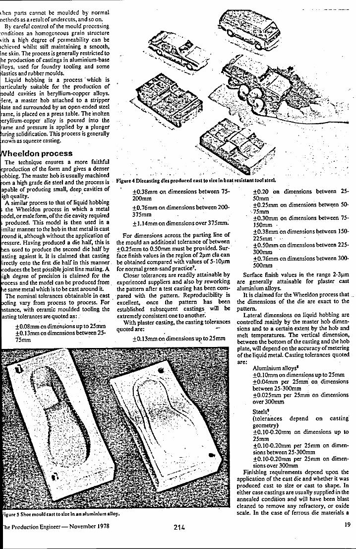
,hen parts cannot be moulded by normal ncthods as a result of undercuts, and so on.
By careful control of the mould processing :onditions an homogeneous grain structure ,,:ith a high degree of permeability can be lchieved whilst still maintaining a smooth, ine skin. The process is generally restricted to
production of castings in aluminium·base used for foundry tooling and some and rubber moulds.
hobbing is a process' which is ,antic",larlv suitable for the production of
cavities in beryllium·copper atloys. a master hob attached to a stripper
surrounded by an open·ended steel is placed on a press table. The inolten
alloy is poured into the and pressure is applied by a plunger solidification. This process is generaUy as squeeze casting.
eldon process technique ensures a more faithful
ieP,roduction of the form and gives a denser master hob is usuaUy machined
grade die steel and the process is of producing small, deep cavities of
quality. . A similar process to that of liquid hobbing the Wheeldon process in which a metal
or male form. ofthe die cavity required pnodllced. This model is then used in a
manner to the hob in that metal is cast it, although without the application of
IresSllre. Having produced a die half, this is used to produce the second die half by
against it It is claimed that casting onto the first die half in this mannef
Irodu,cesthe best p6ssiblejoint line mating. A degree of precision is claimed fOf the
and the model can be produced from. metal which is to be cast around it.
nominal tolerances obtainable in cast vary from process to process. For '
~stance, with ceramic moulded tooling the lastin:g t()!eranl:esare quoted as: .
±O.08mm on dimensions up to 25mm ±O.I3mm on dimensions between 25-75mm .
Production Engineer- November 1978
Figure 4 Dieeasting dies produced cast to size in bea~ resistant tool steel.
±O.38mm on dimensions between 75-200mm
±O.76mm on dimensions between 200-375mm
± 1.14mm on dimensions over 37Smm~
For dimensions across. the parting line of the mou1d an addition'al tolerance of between ±O.25mm to O.50mm must be provided. Sur-' face finish values in the region of2J.lm cIa can be obtained compared with values of 5-1O~m for nor,mal green·sand practice'.
Closer tolerances are readily attainable by experienced suppliers and also by reworking the pattern after a test casting has been compared with the pattern. Reproducibility is excellent, once the pattern has been established subsequent castings will be extremely consistent one to another:
With plaster casting, the casting tolerances quoted are:
±O.13mm on dimensions ul' to 25mm
... .....
214
." .
±O.20 on dimensions between 25-50mm
, ±O.2Smm on dimensions betwt;.en 50-·75mm . ±O.3Omm on dimensions between 75-150mm . ±O.38rrun on dimensions ~etween 150-225mm . ±O.SOmm on dimensions between 225-300mm ±O.76mm on dimensions between 300-500mm
Surface finish values in the range 2·3J.lm are generally attainable for plaster cast aluminium alloys.
It is claimed for the Wheeldon process that. the dimensions of the die are exact to the pattern.
Lateral dimensions on liquid hobbing are controlled mainly by the master hob dimensions and to a certain exten.t by the hob and melt temperatures. The vertical dimension, between the bottom of the casting and the hob plate, will depend on the accuracy of metering of the liquid metal. Casting tolerances quoted are:
Aluminium alloys' ±O.lDmm on dimensio,ns up to 25mm ±O.04mm per 25mm on dimensions between 25·300mm . ±O.025mm per 25mffi on dimensions over300mm
Steels' (tolerances depend on casting" geometry) ±O.10-O.20mm on dimensions up to 25mm to. IO-O.2Omm per 25mm on dimensions between 25·300mm ±O.I().().20mm per 25mm on dimensions over 300mm
Finishing requirements depend upon the application of the cast die and whether it was produced cast to size or cast to shape. In either case castings are usually suppli'ed in the annealed condition and will have been blast cleaned to remove any refractory. or oxide scaJe. In the case of ferrous die materiaJs a
19
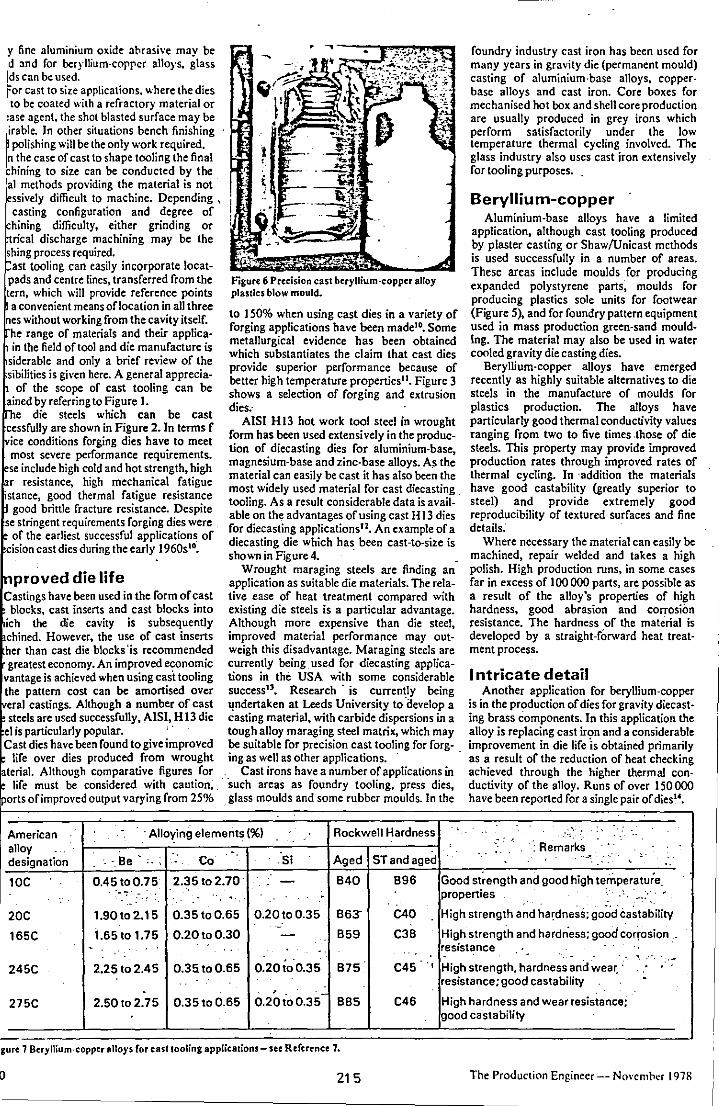
y fine aluminium oxide 3brasive may be d and for beryllium-corper alloys, glass Ids can be used. "'or Cast to size applications ...... here the dies to be coated with a refractory material or ase agent, the shot blasted surface may be irable. In other situations bench finishing polishing will be the only work required.
n the case of cast to shape tooling the final hining to size can be conducted by the
al methods providing the material is not· essively difficult to machine. Depending \ casting configuration and degree of hining difficulty, either grinding or trical discharge machining may be the shing process required. ast tooling can easily incorporate locat
pads and centre lines, transferred from the tern, which will provide reference points a convenient means oflocation in all three
nes without working from the cavity itself. he range of materials and their appticain the field of tool and die manufacture is
siderable and only a brief review of the sibilities is given here. A general apprecia-
of the scope of cast tooling can be ained by referring to Figure I.
e die steels which can be cast cessfully are shown in Figure 2. In terms f ice conditions forging dies have to meet most severe performance requirements. se include high cold and hot strength, high r resistance, high mechanical fatigue
istance, good thermal fatigue resistance good brittle fracture resistance. Despite
se stringent requirements forging dies were of the earliest successful applications of
cision cast dies during the early 196051°.
proved die life Castings have been used in the form of cast
blocks. cast inserts and cast blocks into ich the die cavity is subsequently chined. However, the use of cast inserts her than cast die blocks'is recommended greatest economy. An improved economic
vantage is achieved when using cast tooling the pattern cost can be amortised Over eral castings. Although a number of cast steels are used successfully, AISI, H 13 die
el is particularly popular. . Cast dies have been found to give improved
life over dies produced from wrought aterial. Although comparative figures for
life must be considered with caution, arts of improved output varying from 25%
Figure 6 Precision cast beryllium-copper alloy plastics blow mould.
to 150% when using cast dies in a variety of forging applications have been made'o• Some metallurgical evidence has been obtained which substantiates the claim that cast dies provide superior performance because of better high temperature properties11• Figure 3 shows a selection of forging and extrusion dies ..
AISI HI3 hot work tool steel in wrought form has been used extensively in the production of diecasting dies for aluminium-base, magnesium-base and zinc-base alloys. A.s the material can easily be cast it has also been the most widely used material for cast diecasting tooling. As a result considerable data is available on the advantages of using cast HI3 dies for diecasting applications12• An example ofa diecasting die which has been cast-ta-size is shov.'D in Figure 4. - _
Wrought maraging steels are finding an application as suitable die materials. The relative ease of heat treatment compared with existing die steels is a particular advantage. Although more expensive than die steel, improved material performance may outweigh this disadvantage. Maraging steels are currently being used for diecasting applications in the USA with some considerable success13• Research - is currently being l!ndertaken at Leeds University to -(tevelop a casting material, with carbide dispersions in a tough alloy maraging steel matrix, which may be suitable for precision cast tooling for forg-ing as well as other applications. -
. Cast irons have a number of applications in . 'such areas as foundry tooling. press dies, . glass moulds and some rubber moulds. In the
foundry industry cast iron has been used for many years in gravity die (permanent mould) casting of aluminium-base alloys. copperbase alloys and cast iron. Core boxes for mechanised hot box and shel1 core production are usually produced in grey irons which perform satisfactorily under the low temperature thermal cycling involved. The glass industry also uses cast iron extensively for tooling purposes. _
Beryllium-copper Aluminium-base alloys have a limited
application, although cast tooling produced by plaster casting or Shaw/Unicast methods is used successfully in a number of areas. These areas include moulds for producing expanded polystyrene parts, moulds for producing plastics sole units for footwear (Figure 5), and for foundry pattern equipment used in mass production green-sand moulding. The material may also be used in water cooled gravity die casting dies.
Beryllium-copper alloys have emerged recently as highly suitable alternatives to die steels in the manufacture of moulds for plastics production. The alloys have particularly good thermal conductivity values ranging from two to five times .those of die steels. This property may provide improved production rates through improved rates of thermal cycling. In 'addition the materials have good castability (greatly superior to steel) and provide extremely good reproducibility of textured surfaces and fine details.
Where necessary the material can easily be machined, repair welded and takes a high polish. High production runs, in some cases far in excess of 100 000 parts, are possible as a result of the alloy's properties of high hardness, good abrasion and corrosion resistance. The hardness of the material is developed by a straight-forward heat treatment process.
I ntricate detail Another application for beryllium-copper
is in the production of dies for gravity diecast· ing brass components. In this application the alloy is replacing cast iron and a considerable improvement in die life is obtained primarily as a result of the reduction of heat checking achieved through the higher thermal con· ductivity of the alloy. Runs of over 150000 have been reported for a single pair of dies 1 ...
American alloy designation
, Alloying elements (%) Rockwell Hardness
10C
20C
165C
245C
275C
" -, Be ' ... Co Si
0.45toO.75 2.35 to 2.70 -- ~-
1.90t02,15 0.35toO.65 0.20toO.35
1.65to 1.75 0.20 to 0.30
2.25 to 2.45 0.35. to 0.65 0.20ioo.35
Aged
840
B6:>
859
875
2.50t02.75 0.35toO.65 0.20ioo.35 885
gurt 7 Beryllium-copper allo)"s for casltooling applications - see Reference 7.
215
ST and aged
896
C40
C38
': Remarks _.,J • '. ~ •
Good st~ength and good high temperature. properties .
High strength a~d hardness; go~d castability
High strength and hardn-ess; good corrosion _ re~a~e '
~: .. -C45 " High strength, hardness and wear, .
resistance: good castability
C46 High hardness and wear resistance; good cast ability
The Production Engineer-- No\'cmh(!r 1978
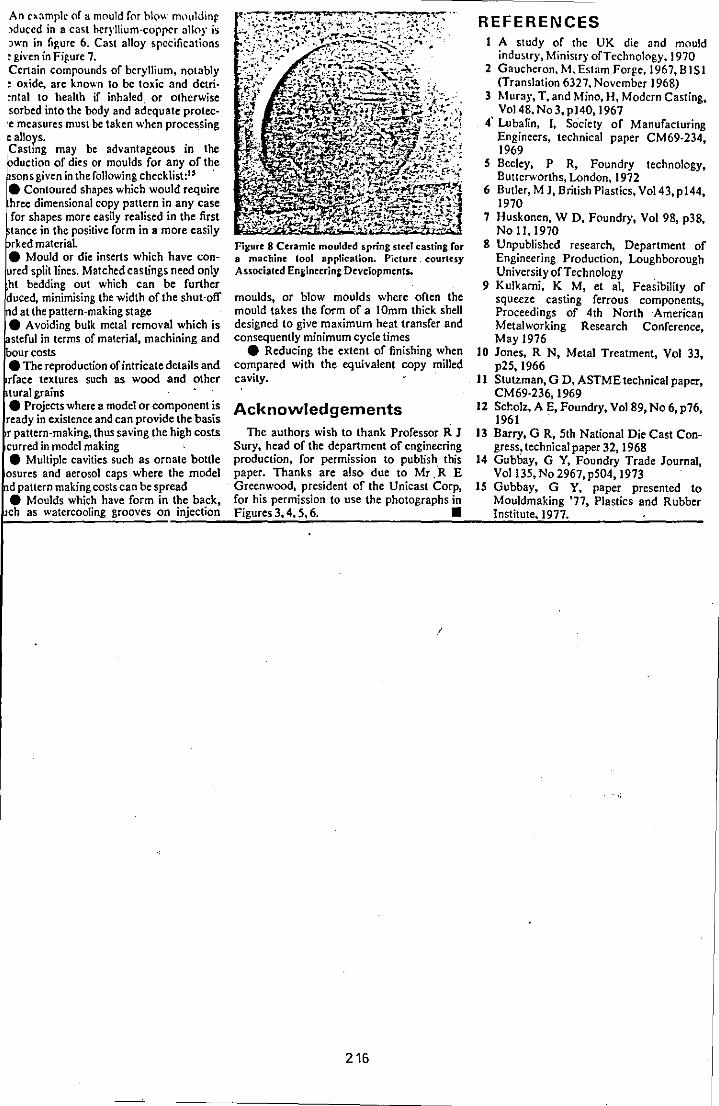
An o,:Jmplc or a mould for hlo\l. nllluldinr :lduccd in a cast heryllium-copper allo), is REFERENCES :Jwn in figure 6. Cast alloy specifications I A study of the UK die and mould = given in Figure 7. indu!.lry. Ministry of Technology. ) 970 Certain compounds of beryllium, notably 2 Gaucheron, M. Est.m Forfe, 1967, B 151 : oxide. are known to be toxic and delri- (Translation 6327. November J 968) ~ntal to health if inhaled or otherwise 3 Mural', T. and Mina, Ht Modern Casting. ,sorbed into the body and adequate prote<· Vo148. No 3, p140, 1967 'C measures must be taken when procesSing 4' LubaRn, ], Society of Manufacturing e alloys. Engineers, technical paper CM69·234, Casting may be advantageous in the 1969 bduction of dies or moulds for any of the S Becley, P R, Foundry technology, sons given in the following checklist:" . Buttcrworlhs, London, 1972
• Contoured shapes which would require 6 BUller, M J, British Plastics, Vo143, p144, hree dimensional copy pattern in any case 1970 for shapes more easily realised in the first 7 Huskonen, W D, Foundry, Vol 98, p38, tance in the positive form in a more easily No 1 1,1970 rked material. Figure 8 Ceramic moulded spring steel casting for 8 Unpublished research, Department of
• Mould or die inserts which have con- 8 machine 1001 application. Picture. courtesy Engineering Production, Loughborough ured split lines. Matched castings need only Associated Engineering Devc1opments. University of Technology . ht bedding out which can be further 9 Kulkami, K M, et ai, Feasibility of duced, minimising the width of the shut-off moulds, or blow moulds where often the squeeze casting ferrous components, datthepattern-makingstage mould takes the form of a IOmm thick shell Proceedings of 4th North American • A voiding bulk metal removal which is designed to give maximum heat transfer and Metalworking Research Conference, sterul in terms of material, machining and consequently minimum cycle times May 1976 our costs • Reducing the extent of finishing when 10 Jones, R N, Metal Treatment, Vol 33, • Thereproduction of intricate details and compared with the equivalent copy milled p25, 1966 rface textures such as wood and other cavity. 11 Stutzman, G D, ASTME technical paper, turalgrains CM69·236,1969 • Projects where a model or component is Acknowledgements 12 Sc~olz, A E, Foundry, Vo189, No 6, p76, ready in existence and can provide the basis 1961 . r pattern-making, thus saving the high costs The authors wish to thank Professor R J 13 Barry, G R, 5th National Die Cast Con-curred in model making Sury, head of the department of engineering gress, technical paper 32, 1968 • Multiple cavities such as ornate bottle production, for permission to publish this 14 Gubbay, G Y, Foundry Trade Journal,
osures and aerosol caps where the model paper. Thanks are also due to Mr.R E Vol135,N02967,p504,1973 d pattern making costs can be spread Greenwood, president of the Unicast Corp, 15 Gubbay, G Y, paper presented to • Moulds which have form in the back, for his permission to use the photographs in Mouldmaking '77, Plastics and Rubber ch as watercooIing grooves on...::.in~je=c:.:ti:o:::n:....:..F:!ig:::u::.re:;s:..:3::,.:4.!., 5:::,:.:6::.. _________ .:.=-_....::In::.:s::.ti::.:tu::.:t:::.e.""1:.:9~7:..!7.:... ____ --':..... __ _
216
NEW FRONTIERS IN Tool Materials
Cutting Techniques
Metal Forming International Conference at Mount Royal Hotel.
London.15th & 16th March 1979
§ESSION V
PAPER 2
PRECISION-CAsr TOOLING
by
A. Clegg and Dr. A.A. Das University of Loughborough
217
En7in~ers' Digest Technical Conferences
PREC I S I Oil CAST TOOL! NG
by Mr A. J. Clegg and Or A. A. Das, Department of Engineering Production,
Loughborough Uni versi ty of Technology.
SYNOPSIS
The paper includes an introduction which defines the tenns associated with
precision. cast tooling. A brief description of the processes used in the
precision casting of dies and IlOU1ds follows. Sane materials suitable for
cast tooling are tabulated and their applications =ised. The review
of the important research and developnent work in the field of precision
cast tooling is restricted to tools made of die steels because of the very
wide range of application of these materials. The review concentrates on
the following:
1. Die Life.
2. Metallurgical Quality.
3. Dimensional Accuracy.
Finally the paper provides a brief outline of the work in progress at
Loughborough University of Technology vis-a-vis the co-ordinated die and
IlOUld research programne of the Science Research Council (SRC).
The concept of precision cast tooling is not new. The demand for precision
cast dies originated fron the aircraft industry's requirEmmt for dies made
in alloys which are difficult tq Imchine. The die gecmetry can be relatively
canplex, e.g. for turbine blades and a high degree of dimensional accuracy
is required. Although work bad been undertaken in Germany before World :War . "
II it was not until the British Aircraft industry initiated research that a casting method - the Shaw process, with real potential for producing
precision cast dies, was developed (1).
In spite of the potential of the Shaw process the commercial feasibility of
using cast dies was not investigated in the UK until the late 1950's and
early 1960's.
218
- 2 -
Even then cast tooling did not find acceptance in the UK die and rrould
industry on the scale of acceptance enjoyed in other European countries,
Japan and the USA (2, 3, 4).
In the UK, die and IIOUld users have been reluctant to use cast products
because of concern that they may cbntain defects such as: microporosi ty ,
blow-holes, segregation, surface imperfections and variations in the
IOOtallurgical structure. Additionally die users have questioned the
degree of·precision obtainable in the ctimensions of the die cavity and
the reproducibility of tolerances. Developnents in foundry technology
during the past two decades have resulted in a considerable improvEJDellt
in casting quality and precision. The ability of a.precision casting
foundry to guarantee casting integrity and accuracy, and the ever increas
ing cost of traditional die making techniques, have resulted in a revival
of interest in cast tooling which is now being used in a variety of
applications. The casting process is often the cheapest and IlOst convenient
IOOthod of producing intricate detail and ~lex shapes in a wide variety
of alloys. No other process provides such freedom and flexibility for the
designer.
DEFINITICN OF TERMS
Several tenns including: 'precision cast tooling'. 'cast to size' and
'cast to shape' are currently used to describe cast dies and IlOUlds for
use in a variety of applications. Although each tenn implies that a
precision casting process has been used to produce the die or IlOUld there
is a significant difference in the degree of die finishing required. 'Cast
to size' implies that the casting accurately resanbles the part required and
that only a minimum arrount of bench fitting is necessary to prepare the die
or rrould for use in production. On the other hand 'cast to shape' indicates
that although the casting closely resembles the required shape of the die or
IIOUld it incorporates a pre-detennined machining and finishing allowance.
The quality of precision (5) enCCIllPasses not only the accuracy of individual
dimensions but surface finish and general appearance. An ideal casting v.ould
not only fall within specified dimensional tolerances but its outlines v.ould
be crisp and clear cut and its surfaces SllXX)th. With precision is coupled
the quality of intricacy. seen in the reproduction of elaborate features and
219
- 3 -
fine detail. Although measures taken by the foundry to increase precision
can result in increased costs, increased accuracy may reduce the total costs
by the reduction or elimination of machining, particularly where difficult
contours, av.kward access or difficult to machine alloys are involved.
PRECISION CASTING PBXESSES
Although there are several precision casting processes available to the
founder the rost camonly adopted process for the production of precision
cast tooling is the Shaw process or its variant the Unicast process. These
processes have the particular advantage that they may be used to produce
castings in a wide range of ferrous and non-ferrous alloys. In view of the
importance of the process in the successful production of precision castings
a brief description will not be out of place. The essential prerequisite to
successful.precision castings are accurately produced patterns. and rould
equipnent. A casting cannot be rore accurate than the pattern fron which it
is produced. The IIOUld material is prepared by blending refractory pcm:l.ers,
containing a high proportion of fine material, vd.th a liquid ethyl silicate
binder and a gelling agent. Careful selection of the refractory material
results in tv.u particular advantages:
(i) The fine grains of refractory material provide a SIOOth surface finish
on the resultant casting.
(H) The selection of a thermally stable refractory material ensures that
the IIOUld is not subject to unpredictable dimensional changes in
contact with the rolten metal during pouring, thus enabling an accurate
estimate of casting contraction to be made.
The blended liquid slurry is poured into the IIOulding box and around the
pattern. Within a short period of time, controlled by the anount of gelling
agent, the IIOuld material gels to a rubbery consistency and the pattern can
be reroved fran the IIOUld. Benefits gained at this stage include:
(a) Pouring a liquid slurry around the pattern ensures a hlgh degree of
contact and therefore accuracy and intricacy in the final casting.
220
- 4 -
(b) The I!X)uld material sets in contact with the pattern and consequently
produces a I!X)uld ~nich accurately reproduces the pattern detail.
(c) The rubbery nature of the I!X)Uld allows the pattern to be withdrawn
~1thout distortion to the mould thus ensuring dimensional accuracy of
the I!X)Uld cavity.
On reroval of the pattern the I!X)ulds are either torched imnediately to_ rerove
evolved alcohol (Shaw process) or :imnersed in a stabilising bath prior to
torching (Unicast Process). Torching produces a very fine crazed surface on
the I!X)Uld which does not affect the casting surface i.e. no metal penetration
into the fine cracks, but does provide I!X)Uld penneability to allow the escape
of air/gases during casting. After torching the I!X)Ulds are fired in a furnace
to a tenperature of 10ClJoC vmich ensures that there are no canbustible materials
-in the I!X)uld and that a strong, rigid, inert, accurate and stable rorud is
produced. - The stages in the production of a die by the ceramic rorud process
are outlined in the flow diagram presented in Figure 1.
Metal can be poured into hot or cold I!X)Ulds and if the I!X)Uld is contained
within an inert atrosphere, for example nitrogen, a clean casting free fron
oxide scale is produced. Careful control of rorud production and metal
melting and treatment enables an accurate prediction of casting contraction
allowances to be made thus ensuring the accuracy and soundness of" the final
casting.
Several other precision casting processes are available and are used in the
production of cast tooling. Plaster casting is suitable for aluminium-base
alloys which can be used for sore plastics and rubber roulds. Liquid bobbing
or 'squeeze casting' has been used successfully for the production of
beryllium--copper tooling. In another process, metal is cast around a male
pattern to f?nD a fanale die cavity and the second die half is cast against
the first die half to ensure accurate matching, this process is known as
the Wheeldon process. The principle of 'squeeze casting"' is shown in Figure
2 and that of the Wheeldon process in Figure 3.
221

- 5 -
FIGURE 1: Flow diagram representing the stages iri the production of a
die by the ceramic mould process.
-Precision Pattern lbulding Box
I I I
Slurry Investment
I Mould Gelling
I . Pattern Removal
T
·1 Mould Ignition lbuld Stabilisation
(Shaw) (Unicast)
I Mould Ignition
J I
lbuld Firing
I Casting
I Knockout
T . Heat Treatment
1 Finishing
222
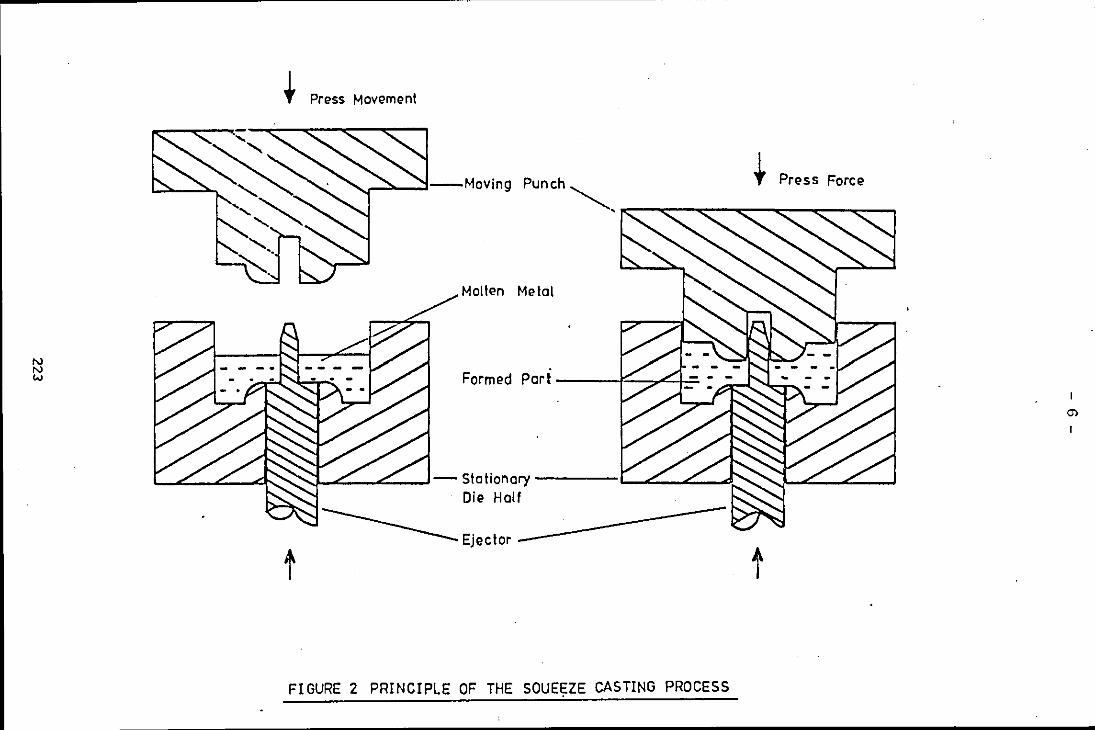
N N W
~ Press Movement
punch"",~ __ ~ __ ~ __ ~t __ ~p~r_e_s~s~F_o_rc~e~~
Molten Metal
Form ed Par I -----I'=~7""!_+=
.....,. ...... :::...-_~_-l- Sta tionary ----I-....c._....c._...d. Die Half
-------Ejector ------------
FIGURE 2 PRINCIPLE OF THE SOUE\,ZE CASTING PROCESS

- 7 -
FIGURE 3 PRODUCTION OF A DIE BY THE WHEELDON PROCESS.
3 A PRODUCTION OF FIRST DIE HALF.
, , , . , , , , , . .. . . ... . I· • • . .. .....,.
SAND MOULo--!-' -, r-------------.., , - , , FIRST
- '-· , .
---l_ f-,-"-:'. -'-', I- 01 E HA LF " '
MASTER METAL PATTERN
3 B PRODUCTION OF SECOND DIE HALF.
SAND MOULD--l-•
. . . .• . . .. . .. ..
I I
. . . . •
: ....... : ...... :;. . . . ... . .. . •
· . . , . SECOND
, , DIE HALF ' , . , . ,
- . . , , FIRST , , , . . . .
· ' , DIE HALF . •
, . . , . . . , .. ... ~~---------~--~----~ . ... .. ,. .. .. . .. . .. .. , . , . . . .. .. . . .. .. . . .. ... . .. . . . .
3C CO'-IPLETED DIE SET.
SECOND DIE '" -'''cl---
HALF
JOINT LINE ----MATCHING
~-->o."-----=-oo::!::~::. __ ~ MAS TER ,PATTERN
REMOVED
FIRST DIE +-1--
HALF
224
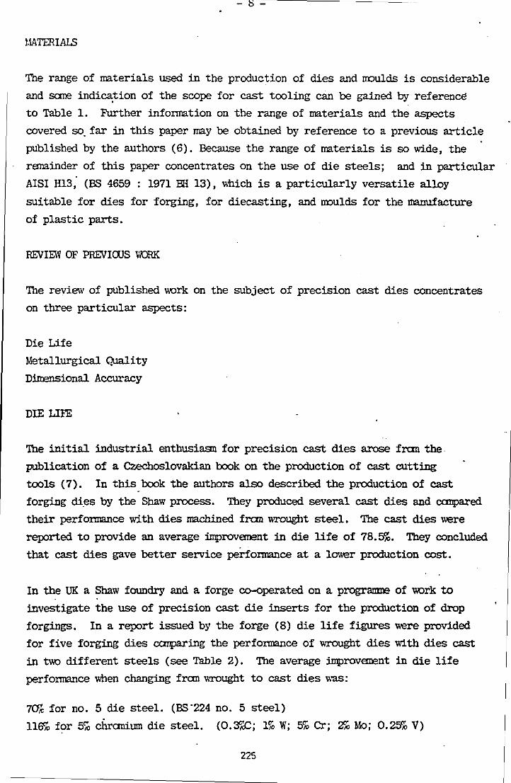
- s -
1.IATERIAlS
The range of materials used in the production of dies and lIOulds is considerable
and sane indication of the scope for cast tooling can be gained by reference
to Table 1. Further information on the range of materials and the aspects
covered so. far in this paper may be obtained by reference to a previous article
published by the authors (6). Because the range of materials is so wide, the
remainder of this paper concentrates on the use of die steels; and in particular
AISI H13, (BS 4659 : 1971 EH 13), v.hich is a particularly versatile alloy
suitable for dies for forging, for diecasting, and lIOulds for the manufacture
of plastic parts.
REVIEW OF PREVICXJS WORK
The review of published work on the subject of precision cast dies concentrates
on three particular aspects:
Die Life
Metallurgical Quality
DiIrensional Accuracy
DIE LIFE
The initial industrial enthusiasn for precision cast dies arose fron the
publication of a Czechoslovakian book on the production of cast cutting
tools (7). In this book the authors also described the production of cast
forging di,es by the Shaw process. They produced several cast dies and canpared
their performance with dies machined fron wrought steel. The cast dies were
reported to provide an average inprovanent in die life of 78.5%. They concluded
that cast dies gave better service performance at a lower production cost.
In the UK a Shaw foundry and a forge co-operated on a progr3llID':! of work to
investigate the use of precision cast die inserts for the production of drop
forgings. In a report issued by the forge (8) die life figures were provided
for five forging dies carparing the performance of wrought dies with dies cast
in two different steels (see Table 2). The average improvanent in die life
perfonnance v.hen changing fran wrought to cast dies was:
70% for no. 5 die steel. (BS·224 no. 5 steel)
116% for 5'70 chranium die steel. (0.3"'"c; 1% W; 5% Cr; 2% Mo; 0.25% V)
225

- 9 -
Table 1: Cast ToolinF Materials and AEEl1cations
\
Production Typical Cast.Tooling Process Cast Tooli·ngMaterial Application
Forging H12, H13 and other hot Drop forging dies, hot
work tool steels die forging, press
forging, roll forging
Extrusion Tool Steel Aluminium extrusion
Pressing Cast Iron, S.G. Iron, Automobile pressings
Tool Steel
Diecasting Hl3 tool steel Aluminium-base, coppe~
base, magnesium-base and
zinc-base alloys.
Plastics Moulding Aluminium-base alloys, Shoe moulds. injection
beryllium-copper alloys, moulding,
cast iron, tool steel blow moulding, rubber
moulding.
Glass Moulds Cast Iron, S.G. Iron, Glass bottles, ovenware.
Tool steel.
FoundrY Tooling Aluminium-base alloys, . Mass production patterns
cast iron, alloy irons, and coreboxes. Shell
S.G. irons, tool steel. core and hot box core-
boxes •
.
226

- 10 -
TABLE 2: IMPROVThlENT IN DIE LIFE WHEN CHANGING FRaIl \\IDJGIIT 'ID CAST FORGING DIES
. % Improvanent in Die Life Forging Die
No. 5 steel 5% Cr. steel
-Hub Flange 50 80
Coal Pick 31 69
Connecting Rod 71 136
Coal Pick 116 280
Coal Pick 54 71
A substantial investigation into the use of cast dies for forging applications
was undertaken by· a French team of investigators (2). Several evaluations
using different die steels and die configurations were conducted at different
forges. Sane of the results are presented below:
. SPIDER 'IRANSMISSION FORGING
Two sets of cast dies provided die lives of 22,150 and 19,900 respectively
canpared with the average wrought die life of 9,50).
HUB FORGING
Three sets of cast dies were used in service and provided die lives of 5,a:o,
6,2CO and 8,6CO (an average of 6,60:)) in canparison with the average wrought
die life of 5,800.
One of the trials conducted canpared die lives for cast dies with ascast
impressions, cast die blocks with machined impressions, and wrought die blocks
with machined impressions. Results were reported for two forgings:
LARGE WHEEL HUB
wrought die
cast die - machined impression
cast die - ascast impression
average die life
3,50)
7,50)
8,122
227
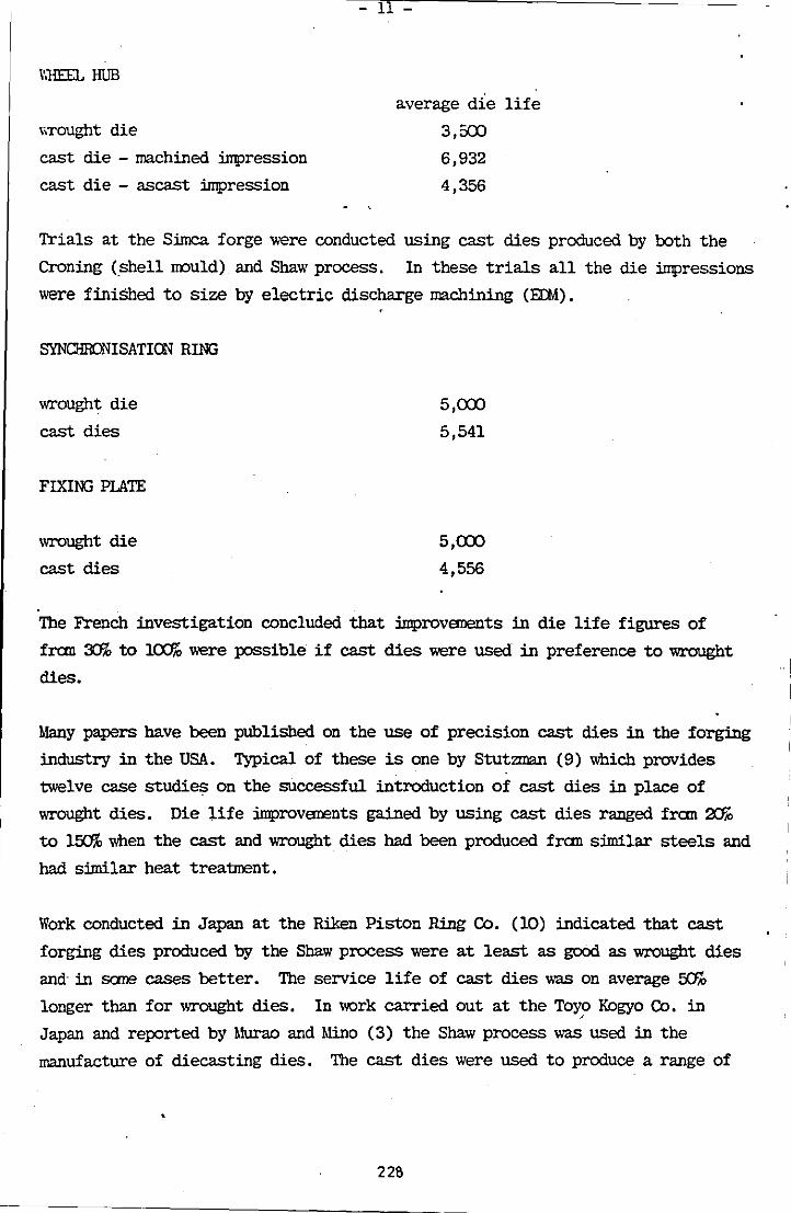
,","HEEL HUB
\\TOUght die
cast die - machined impression
cast die - ascast impression
- 11 -
average die life
3,50:)
6,932
4,356
Trials at the Simca forge were conducted using cast dies produced by both the
Croning (shell IJX)uld) and Shaw process. In these trials all the die impressions
were finiShed to size by electric discharge machining (EI:M).
SYNCHRONISATION RING
wrought die
cast dies
FIXING PLATE
wrought die
cast dies
5,CXX>
5,541
5,CXX>
4,556
The French investigation concluded that improvanents in die life figures of
fron 3Jib to lCX1!O were possible if cast dies were used in preference to wrought
dies.
Many papers have been published on the use of precision cast dies in the forging
industry in the USA. Typical of these is one by Stutzman (9) which provides
twelve case studies on the successful introduction of cast dies in place of
wrought dies. Die life improvenents gained by using cast dies ranged fron 2Jk to l~ when the cast and wrought dies had been produced fran similar steels and
had similar heat treatment.
Work conducted in Japan at the Riken Piston Ring Co. (10) indicated that cast
forging dies produced by the Shaw process were at least as good as wrought dies
and- in sane cases better. The service life of cast dies was on average fJ:f!o
longer than for wrought dies. In work carried out at the Toyo Kogyo Co. in .'
Japan and reported by Murao and Mino (3) the Shaw process was used in the
manufacture of diecasting dies. The cast dies were used to produce a range of
228
I
I
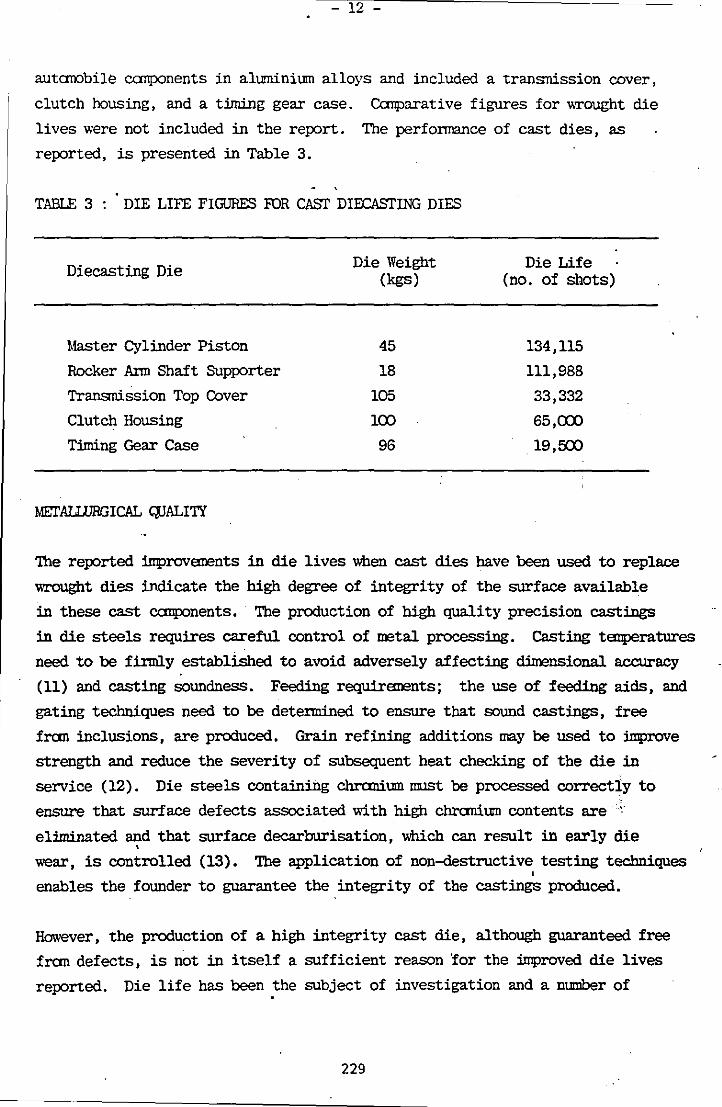
12 -
autarobile canponents in aluminium alloys and included a transnission cover,
clutch hOUSing, and a timing gear case. Canparative figures for v,Tought die
lives were not included in the report. The perfonnance of cast dies, as
reported, is presented in Table 3.
TABlE 3: DIE LIFE FIGURES FOR CA'EIT DIOCASrING DIES
Diecasting Die
1mster Cylinder Piston
Rocker Ann Shaft SUpporter
Transnission Top Cover
Clutch Housing
Timing Gear Case
MEl'AUIJRGICAL C:PALITY
Die Weight (kgs)
45
18
105
100
96
Die Life (no. of shots)
134,115
111,988
33,332
65,a:x>
19,500
'!he reported iIIprovanents in die lives when cast dies have been used to replace
wrought dies indicate the high degree of integrity of the surface available
in these cast components. Tbe production of high quality precision castings
in die steels requires careful control of metal processing. Casting tanperatures
need to be firmly established to avoid adversely affecting climensional accuracy
(11) and casting soundness. Feeding requiranents; the use of feeding aids, and
gating techniques need to be detennined to ensure that sound castings, free
fran inclusions, are produced. Grain refining additions may be used to iIIprove
strength and reduce the severity of subsequent heat checking of the die in
service (12). Die steels containing chranium must be processed correctly to
ensure that surface defects associated with high chranium contents are •• ,"
eliminated and that surface decarburisation, which can result in early die •
wear, is controlled (13). The application of non-<l.estructive testing techniques , enables the founder to guarantee the integrity of the castings produced.
However, the production of a high integrity cast die, although guaranteed free
fran defects, is not in itself a sufficient reason lor the improved die lives
reported. Die life has been ~he subject of investigation and a number of
229

- 13
Jretallurgica1 reasons for the improved perfonnance of cast dies have been
suggested. An investigation of factors affecting heat checking revealed
that although heat checks propagate in a sllni1ar manner in both cast and
\lTought dies, in cast dies they eh"tend into the casting to a shallow depth
and then stop. It is suggested that the lack of directionality in the grain
structure of castings is a significant factor (14). The non-directional
grain structure of the cast die material is also claimed to reduce residual
stresses ~thin the die and as a result castings do not warp or distort during
heat treatinent to the extent that wrought dies do (12).
Metallurgical investigations canparing the properties of cast and wrought
H13 die materials have been the subject of papers by Stutzman (9, IS, 16).
Eh"tensive tests were undertaken on precision cast and wrought material at
roan and elevated tanperatures. The roan temperature results of ultimate
tensile strength and yield strength were sllnilar for both materials but the
reduction of area and % elongation test results were significantly lower for
the cast material. The difference in values of ductility was less pronounced
in the tests carried out at temperatures of 4800C and 590oC, and negligible
at temperatures of 6&:PC and 705oC. At these latter temperatures the ultimate
~ensile strength and yield strength values for the cast material were slightly
higher than those for the wrought material. Of note was the existence of a
true yield point in the cast· samples v.hl.ch shows that heat treated precision
cast tool steel is not brittle.
The impact strength, measured by the Charpy V notch test, of the cast material
was appreciably lower than the wrought material when tested at both roan and
elevated temperatures but there was no evidence of a brittle fracture. Fatigue
tests indicated that wrought steels were inferior to the cast material when
notched specimens were used. However, with unnotched specimens the wrought
speciJrens were much superior.
Hot hardness tests conducted on material v.hl.ch had been heat treated to give
. a hardness value of Rockwell C40 and C52 indicated that the cast structure
is superior to the wrought structure:
At 31SoC to 42SoC the cast material was 1 RC harder.
2-4 RC harder.
8 RC harder.
" 540°C "" 11 "
" 50CPC to 6&PC" It " It
230
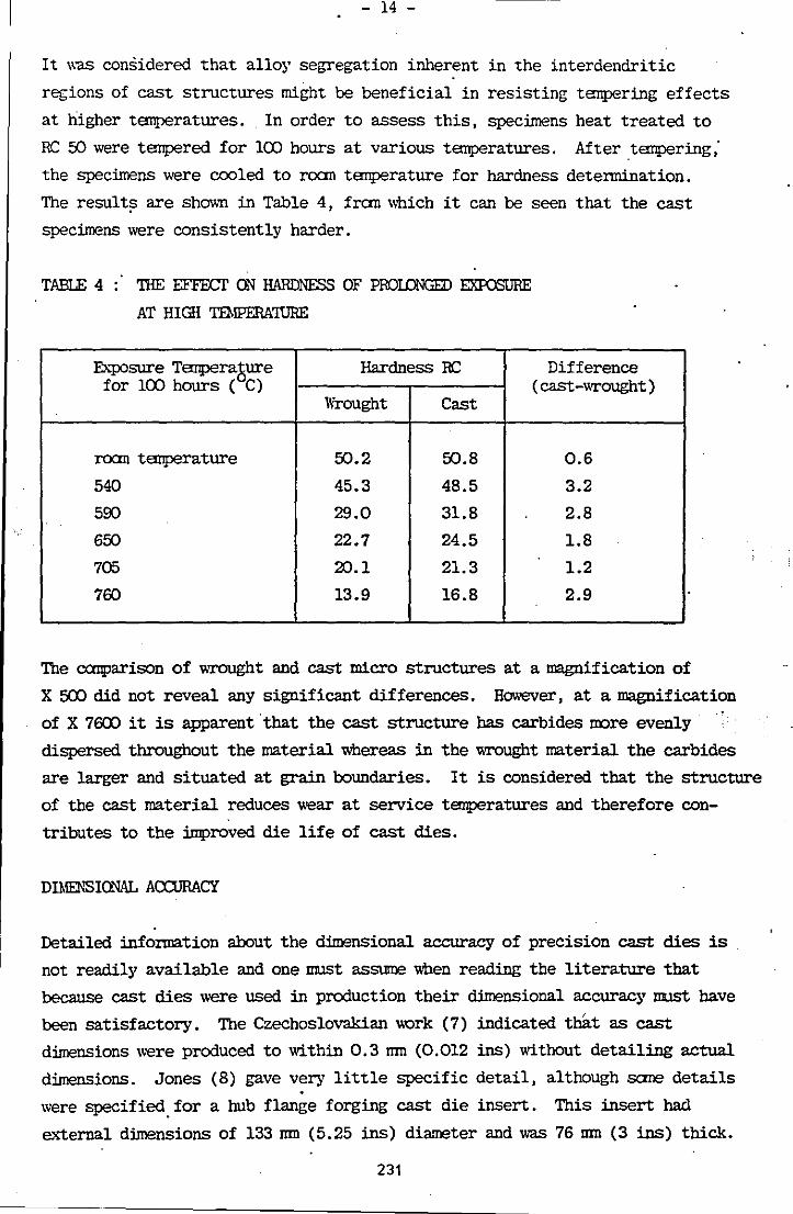
- 14 -
It was considered that alloy segregation inherent in the interdendritic
regions of cast structures might be beneficial in resisting tempering effects
at higher temperatures .. In order to assess this, specimens heat treated to
RC 50 were tempered for 100 hours at various temperatures. After tempering;
the specimens were cooled to roam temperature for hardness determination.
The result~ are shown in Table 4, fron which it can be seen that the cast
specimens were consistently harder.
TABLE 4: THE EFFECI' ON HARDNESS OF PROLONGID EXroSURE
AT HIGH IDIPERA'IURE
Eh-posure Temperasure Hardness RC for 100 hours ( C)
Wrought Cast .
roan temperature 50.2 50.8
540 45.3 48.5
500 29.0 31.8
650 22.7 24.5
705 20.1 21.3
700 13.9 16.8
Difference (cast-wrought)
0.6
3.2
2.8
1.8
1.2
2.9
The canparison of wrought and cast micro structures at a magnification of
X 500 did not reveal any significant differences. However, at a magnification
of X 7fI:IJ it is apparent that the cast structure has carbides IlXlre evenly
dispersed throughout the material v,bereas in the wrought material the carbides
are larger and situated at grain boundaries. It is considered that· the structure
of the cast material reduces wear at service temperatures and therefore con
tributes to the improved die life of cast dies.
DIMEt·lSIONAL ACCURACY
Detailed infonnation about the dimensional accuracy of preCision cast dies is
not readily available and one ImlSt assume when reading the literature that
because cast dies were used in production their dimensional accuracy Iml5t have
been satisfactory. The Czechoslovakian \\Qrk (7) indicated tbll.t as cast
dimensions were produced to within 0.3 mn (0.012 ins) without detailing actual
dimensions. Jones (8) gave very little specific detail, although sane details
were specified. for a hub flange forging cast die insert. This insert had
external dimensions of 133 mn (5.25 ins) diameter and was 76 mn (3 ins) thick.
231
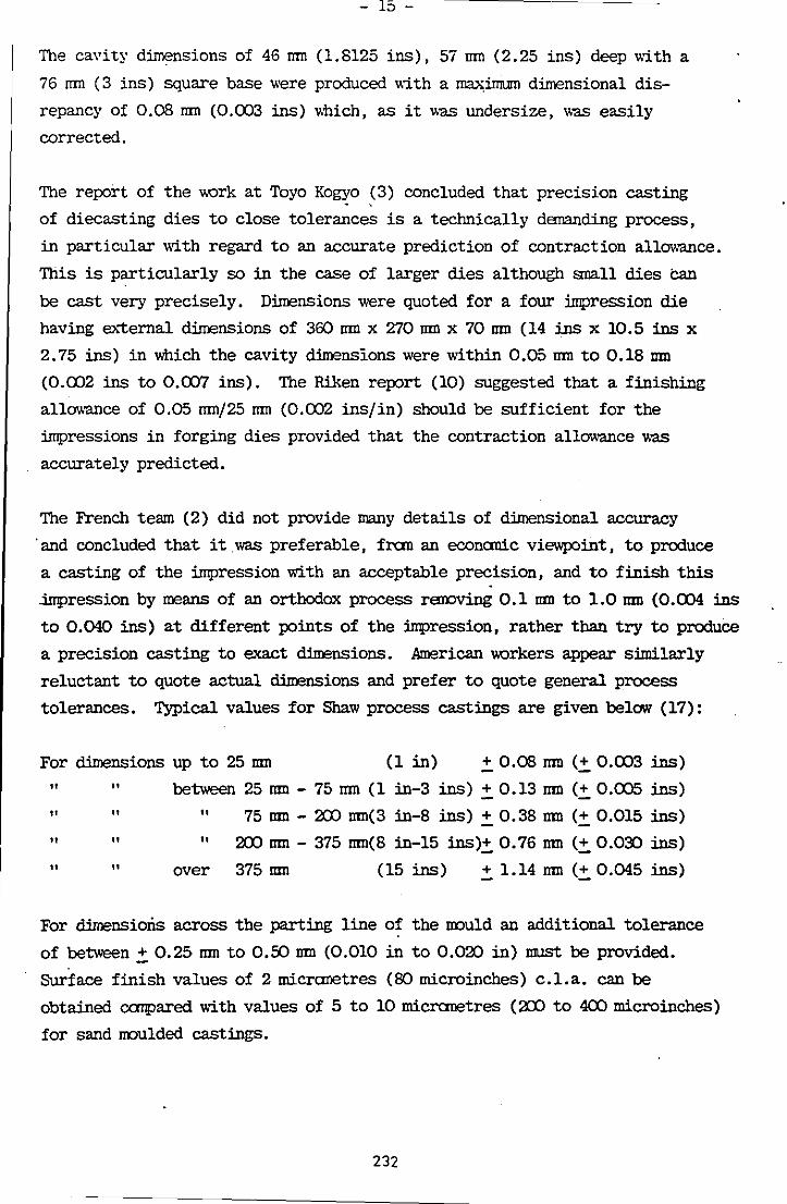
- 15 -
The cavity dimensions of 46 mn (1.8125 ins), 57 mn (2.25 ins) deep with a
76 mn (3 ins) square base were produced with a ~:imum dimensional dis
repancy of 0.08 mn (0.003 ins) v.hich, as it was undersize, was easily
corrected.
The report of the v.urk at Toyo Kogyo (3) concluded that precision casting
of diecasting dies to close tolerances is a technically demanding process,
in particular with regard to an accurate prediction of contraction allowance.
This is particularly so in the case of larger dies although small dies Can
be cast very precisely. Dimensions were quoted for a four linpression die
having el';ternal dimensions of 360 mn x 270 mn x 70 mn (14 ins x 10.5 ins x
2.75 ins) in v.hich the cavity dimensions were within 0.05 mn to 0.18 nm
(0.002 ins to 0.007 ins). The Riken report (10) suggested that a finishing
allowance of 0.05 =/25 mn (0.002 ins/in) should be sufficient for the
impressions in forging dies provided that the contraction allowance was
accurately predicted.
The French team (2) did not provide many details of dimensional accuracy
. and concluded that it was preferable, fron an econanic viewpoint, to produce
a casting of the impression with an acceptable precision, and to finish this
.iIr!Pression by means of an orthodox process rawving 0.1 nm to 1.0 nm (0.004 ins
to 0.040 ins) at different points of the impression, rather than try to produce
a precision casting to exact dimensions. American v.urkers appear s:imilarly
reluctant to quote actual dimensions and prefer to quote general process
tolerances. Typical values for Shaw process castings are given below (17):
For dimensions up to 25 mn (1 in) .!. 0.08 roD (.!. 0.003 ins)
" " between 25 roD - 75 mn (1 in-3 ins) .!. 0.13 roD (.!. 0.005 ins)
"" "75 nm - 20) nm(3 in-8 ins) .!. 0.38 nm (.!. 0.015 ins)
" " " "
" over
20) nm - 375 nm(8 in-15 ins).!. 0.76 mn (.!. 0.03:) ins)
375 nm (15 ins) .!. l.14 mn (.!. 0.045 ins)
For dimensions across the parting line of the muld an additional tolerance
of between.!. 0.25 mn to 0.50 nm (0.010 in to 0.020 in) ImlSt be provided.
Surface finish values of 2 micranetres (80 microinches) c.l.a. can be
obtained canpared with values of 5 to 10 micranetres (20) to 4(X) microinches)
for sand mulded castings.
232
- 16 -
To summarise, the precision casting process is suitable for the production of
cast dies of high metallurgical quality and capable of providing die lives as good, or better, than dies machined fran wrought material. Dimensional
accuracy noses the greatest problan to the founder and producing dies 'cast
to size' is a very dananding technical exercise. However, the production of
• cast to shape' dies which incorporate a pre-cietennined finishing allowance
is a task which is easily accomplished by the competent precision foundry.
The die user nrust determine carefully which is the IIOre econanical· route to
a finished die, the precision casting route or the traditional dianaking route.
Certainly the preCision casting route should be given ample consideration.
RESEARCH AT LOUGHOORaJGH
The authors are currently engaged on a research project on the optimisation
of materials and methods in the production of precision cast tooling, which
is financed by the SRC under the auspices of the Die and Mould research
progranrne. The SRC progranrne is not restricted to precision casting. It
covers electric discharge machining, electrochanical machining, heat treatment,
surface coating, beat transfer, canputer aided design, and the econanics of
die and IIOUld manufacture.
The project at lDughborough is directed towards the establishment of methods
and procedures for the production of precision cast tooling and to an indepen
dent assessment of the degree of accuracy attainable in the cast product. A
canparison of the surface integrity of as cast surfaces and ID! surfaces is
also included in the programne. To this end cast tools are being produced
to speCifications prepared by canpanies co-operating with the research
programne. Casting trials have yet to be canpleted and involve the production
of three tools in HI3 die steel:
1. A retractable diecasting die core incorporating a cast thread.
2. A drop forging die for the production of a flange yoke transmission
forging.
3. A drop forging die for ~he production of a spider transmission
forging.
233

ACKl\UWLElX,D!El\'TS
The authors vd.sh to thank Professor R J Sury, head of the Department of
Engineering Production for the facilities and permission to publish this
paper.
231.
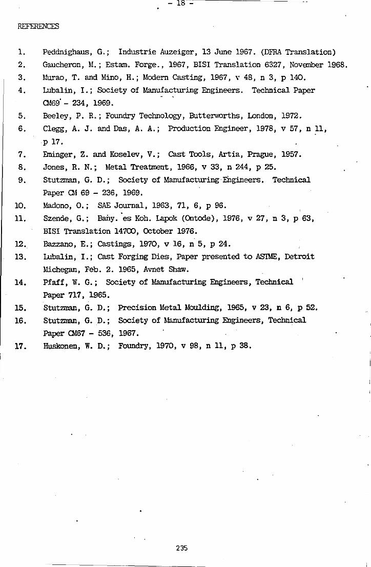
18 -
REF'E1lENCES
1. Peddnighaus, G.; Industrie Auzeiger, 13 June 1967. (DFRA Translation)
2. Gaucheron, M.; Estam. Forge., 1967, BISI Translation 6327, November 1968.
3. Murao, T. and Mino, H.; Modern Casting, 1967, \' 48, n 3, p 140.
4. Lubalin, I.; Society of Manufacturing Engineers. Technical Paper
0.169· - 234, 1969.
5. Beeley, P. R.; Foundry Technology, Buttenrorths, London, 1972.
6. Clegg, A. J. and Das, A. A.; Production Engineer, 1978, v 57, n 11,
p 17.
7. Elninger, Z. and Koselev, V.; Cast Tools, Artia, Prague, 1957.
8. Jones, R. N.; Metal Treatment, 1966, v 33, n 244, p 25.
9. Stutzman, G. D.; Society of ManufacturingEOgineers. Technical
Paper CM 69 - 236, 1969.
10. Madono, 0.; SAE Journal, 1963, 71, 6, P 96.
11. Szende, G.; Baby. ·es Koh. Lapok (Ontode), 1976, v 27, n 3, p 63,
BISI Translation 14700, October 1976.
12. Bazzano, E.; Castings, 1970, v 16, n 5, p 24.
13. Lubalin, 1.; Cast Forging Dies, Paper presented to AS'ThIE, Detroit
Iv!ichegan, Feb. 2. 1965, Avnet Shaw.
14. Pfaff, W. G.; Society of Manufacturing Engineers, Technical '
Paper 717, 1965.
15. Stutzman, G. D.; Precision Metal Moulding, 1965, v 23, n 6, p 52.
16. Stutzman, G. D.; Society of Mmufacturing Engineers, Technical
Paper CM67 - 536, 1967.
17. Huskonen, W. D.; Foundry, 1970, v 98, nIl, p 38.
235
roundr)' Tr.,de Journ<ll SI ptcmbcr 11, 1980
The Shaw Process-a Review By A. J. Clegg*
The Shaw Process is a precision C9Sti~g process suitable for the production of castings In a wide range of casting alloys. This article reviews the factors of importance in the production of moulds and castings by the Shaw Process. In particular, the author considers the binder system, refractory aggregates, moulding procedure, and metallurgical and dimensional quality of steel castings produced by the process.
The Shaw Process is a precIsion casting process capable of the production of accurate castings with excellent surface finish and metaIlurgical integrity. Moulds are produced using highly refractory aggregates bonded with silica provided by a liquid ethyl silicate binder. A high temperature firing treatment is a feature of the production sequence and this produces an inert mould into which the majority of commercial ferrous and non-ferrous alloys can be cast with confidence. The process has been used commercially for many years; it was known before the Second World War that silicon esters could be used as refractory aggregate bindersl. As with most processes there has been a continuous development, in particular with respect to the binder system and the methods of mould production. Many of these developments are the subject of patents and much of the technical information bas been restricted to Shaw Process licensees. As a result, the process may not have received the interest and support by the UK foundry industry that its qualities deserve. At a time when there is an increasing demand for castings with guaranteed quality, dimensional accuracy and metallurgical integrity, it may be appropriate to consider the possibilities that the Shaw Process offers.
Outline of the Process The mould material is prepared by blending refractory powders, containing a high proportion of fine material, with a liquid ethyl silicate binder and a gelling agent. Careful selection of the refractory material results in two panicular advantages:
1 The fine grains of refractory material provide a smooth surface finish on the resultant casting. 2 The selection of a thermally stable refractory material ensures that the mould is not subject to
• The author is a leC1urer in the Depanment of Engineering Production at Loughbnrough Univenit)' of Technology,
236
unpredictable dimensional changes in contact with the molten metal during pouring, thus enabling an accurate estimate of casting contraction to be made. The blended, mobile liquid slurry is poured into the
. moulding box and around the pattern. Within a short period of lime, connolled by the amount of gelling agent, the mould material gels to a rubbery consistency and the panern can be separated from the mould. The nature of the process permits certain benefits to be gained at this stage:
a Pouring a Jiquid slurry around the pattern ensures a high degree of contact and therefore accuracy and intricacy in the final casting. b The mould material sets in contact with the pattern and consequently produces a mould which accurately reproduces the panern detail. c The rubbery nature of the mould allows the pattern to be withdrawn without distortion to the mould, thus maintaining the dimensional accuracy of the mou1d cavity_
On removal of the pattern the moulds are either lorched immediately to remove evolved alcohol (Shaw Process) or immersed in a stabilising bath
Das Shaw·Verfahren-eine Obersicht van A. J. Clegg
Cas Shaw-Verfahren ist ein Prazisionsgussverfahren, das fur die Herstellung von Teilen in einer grossen Auswahl von Gusslegierungen geeignet ist. In diesem Artikel werden die bei der Herstellung von Formen und Gussteilen nach dem ShawVerfahren wichtigen Verfahren beschrieben. Insbesondere betrachtet der Verfasser dan Bindesystern, Zuschlagstoffe fUr das Feuerfestmaterial, Formverfahren und die metallurgische und dimensionale Qualitat von Stahlgussteilen, die nach diesem Verfahren hergestellt werden.
Etude sur le procede Shaw par A. J. Clegg
Le procede Shaw est une methode de moulage de precision coovenant a la fabrication de pieces en un grand choix d'alliages, Cet article examine les principaul: facteurs qui influencent la fabrication des moules et le moulage des pieces par le procede Shaw. L'auteur se penche en particulier sur les liants, les agregats r~Hractaires, I'operation de moulage et les proprietes metallurgiques et dimensionnelles des pieces realisees par ce procede •
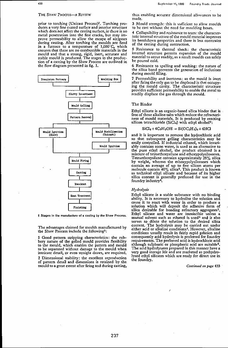
.30
THE SJlAW PHOCESS-A Rn'JEw
prior to larching (l!nicast Process):!. Torching produces a vcry fine crazed surface and interior structure which does not affect the casting surface, ie there is no metal penetration into the fine cracks, but may improve permeability to allow the escape of air/gases during casting. After larching the moulds 3TC fired in a furnace to a temperature of 1,OOO'C, which ensures that there are no combustible materials in the mould and that a strong, rigid, inert, accurate and stable mould is produced. The stages itl the production of a casting by the Shaw Process 3TC outlined in the flow diagram presented in fig. 1.
Precision Pauern
lblld 19n.:1tioa (Shaw)
lb.ll.d 19::rl:tion
1 Stages in the manufacture of a casting by the Shaw Process.
The advantages claimed for moulds manufactured by the Shaw Process include the following3 :
1 Good pattern stripping characteristics; the rubbery nature of the gelled mould provides flexibility to the mould, which enables the pattern and mould to be separated without damage to the mould when intricate detail, or even straight draws, are required. 2 Dimensional stability; the excellent reproduction of panern detail and dimensions is retained by the mould to a great extent after firing and during casting,
237
Scpkmbcr 11, 1980 Foundr), T'adl' JourOill
thus enabling accurate dim('n~ionat allowances to be made.
3 Mould strength: this is ~ufficicnt to allow moulds to be cast without the need for moulding boxes. 4 Collapsibility and resistance to tears: the characteristic internal structure of the mould material improves its breakdown properties and there is less constraint of the casting during contraction. S Resistance to thermal shock: the characteristic internal structure permits expansion of the mould material to occur readily, as a result moulds can safely be poured cold. 6 Resistance to spalling and washing: the nature of the silica bond prevents the generation of inclusions during mould filling.
7 Permeability and inertness: as the mould is inert after firing the only gas to he displaced is that occupying the mould cavity. The characteristic structure provides sufficient permeability to enable the metal to readily displace the gas through the mould.
The Binder
Ethyl silicate is an organic-based silica binder that is free of those alkaline salts which reduce the refractoriness of mould materials. It is produced by reacting silicon tetrachloride (SiCI4) with ethyl alcoho14:
SiCI4+4C2H,OH -+ Si(OC2H,).+4HCl
and it is important, to remove the hydrochloric acid so that subsequent gelling characteristics may be easily controlled. If industrial ethanol, which invariably contains some water, is used as an alternative to the pure ethyl alcohol, the product obtained is a mixture of tetraethoxysilane and etho>..-ypolysiloxanes. Tetraethoxysilane contains approximately 28% silica by weight, whereas the ethoxypolysiloxanes which contain an average of up to five silicon atoms per molecule contain 40% silica5• This product is known as technical ethyl silicate and because of its higher silica content is generally preferred for use in the foundry industry'.
Hydrolysis Ethyl silicate is a stable substance with no binding ability. It is necessary to hydrolise the solution and cause it to react with water in order to produce a solution which will deposit the adhesive form of silica desirable for bonding refractory aggregates? Ethyl silicate and water are immiscible un1ess a mutual solvent such as ethanol is used8 and it also serves to dilute the solution to the desired silica content. The hydrolysis may be carried out under either acid or alkaline conditions4• However, alkaline conditions usually result in fairly rapid gelation and consequently acid hydrolysis is preferred for foundry requirements. The preferred acid is hydrochloric acid although sulphuric or phosphoric acid are suitable8•
The acid hydrolysates prepared in this manner have a very good storage life and are marketed as prehydrolysed ethyl silicates which are ready for direct use in the foundry.
Continued on page 433
I
foufldry Trllch· Journlll Sqllullbcr11,1980
The Shaw Proccss-a Rcview
C01l1;'IIICd from pact 430
Gelation In order to bind the refractory aggregate the ethyl silicate hydrolysate must be made to gel. It is the gel which provides the bonding action by two methods!!:
a Air drying bond:
- 3H,SiO, .... H,Si,O.+H,Si03+4H,O
b Precipitation bond:
3H,SiO, .... 3SiO, ge1+6H,O
Upon heating, the silicic acid or silica gel binders condense to form a refractory silica cement. It is this silica form which provides the high strength developed by firing.
There are many ways of promoting the gelling of an acid hydrolysed ethyl silicate using the principle of pH control 1• Hydrolysed ethyl silicate solutions afe usually prepared with a pH value of between 1·5 and 3'0, at which they are relatively stable, they are also stable at pH values above 7-0. They are inherently unstable at pH values between 5-0 and 7-0. By adding an alkaline agent to the hydrolysed ethyl silicate solution the pH value of the solution can be increased to a value of 5,0 when the binder becomes unstable and gels. Ammonia, ammonia sahs-acetate, carbonate, hydroxide; or organic ammonia salts-piperidine, morpholemar, triethylamine, may be used for this purpose. The actual time for gelation will depend on the panicular application and can be varied by adjusting the amount of gelling agent addition.
If accurate control of setting time or a very long setting time is required use may be made of organotin catalysts5• The organotin catalysts enable hydrolysis and gelation to proceed readily in the absence of either add or base. By a special heat treatment process the gelation characteristics can be altered ,to change the gel time when water is added.
Refractory Aggregates
Many refractory materials may be used in association with ethyl silicate to produce Shaw Process moulds, the list in Table 1 includes many of the possible materials but is not exhaustive. In the selection of a suitable material for a panicular application the foHowing factors must be considered:
1 Purity 2 Refractoriness 3 Stability 4 Thermal Expansion 5 Thermal Conductivity 6 Particle Size and Distribution 7 Cost
The mould material must be sufficiently refractory to withstand the pouring temperature of the panicular metal being cast; '\\ithout either melting or softening.
238
<" TAIiI.[ ): Rt!ral!(lrJl "'(luriO!J Jui,oUt for 10f ill Iht Silof/,' Pr(lltlJ
Maurial Chcmi.:all"otation I .Mching I'uint 'C
Magnesia M~O 2,flOO Zirconia ZrOI 2,677 Calcia C.O 2,600 Zircon Zr02,SiOl 2,420 Calcium zirconite CaO.ZrOI 2,345 Magnesia 5pincl MgO,AI.O, 2,135 Alumina AltO. 2,015 Mullite 3AItO,,2SiO. 1,830 Fused 5ilica SiO. 1,123
The melting point value is a good guide to refractori~ ness providing the material is pure, as very small amounts of alkali metal salts or iron oxide can reduce melting points severely. The refractory selected should exhibit stability, it should not be susceptible to hydration, or reactions with other materials in the mould or the metal. Thermal stability is also important, expansion is inevitable; however, providing that it is predictable, ie constant and reproducible, it can be taken into account when estimating contraction allowance. '
Thermal conductivity is in pan a propeny of the material selected but it is also a function of particle size and distribution when that material is used to produce a porous, particulate mould. The propeny does influence the rate of solidification and heat transfer through a mould which may have an influence on metallurgical integrity.
Cost is a major factor in refractory material selection and is affected by such factors as avaiIabiIity, purity and panicle size requirement.
Moulding Mix Specification The secret of successful mould production and quality castings lies in the mould material mix specification. It is essential to balance the grades of refractory material with the volwne of binder and amount of gelling agent in order to produce moulds of consistently high quality. Shaw Process slurry preparation is critical9, too thin and mould cracking will occur on firing, too thick and detail is Jost and air bubbles are trapped at the pattern surface.
When selecting the grades of refractory material to be used the principles which apply to sand moulding can be used as a guide. Surface finish will be improved when finer material is used ; however, penneability will decrease ari'd binder requirement increase as a consequence. The strength, measured conventionally by AFS compression and tensile strength, will also be affected by grade selection. Strength will be at a maximum when refractory grades are selected on the basis of using se\'eraJ size gradings which permit infilling of the voids between larger grains by the smaller;, this is also the most economic way of using the binder. Mix specification is inevitably a compro~ mise between theoretical considerations and practical requirements but a reading of standard ceramic texts10,l1 can be invaluable.
Experimentally determined values12 of strength
Conr;,med on page 436
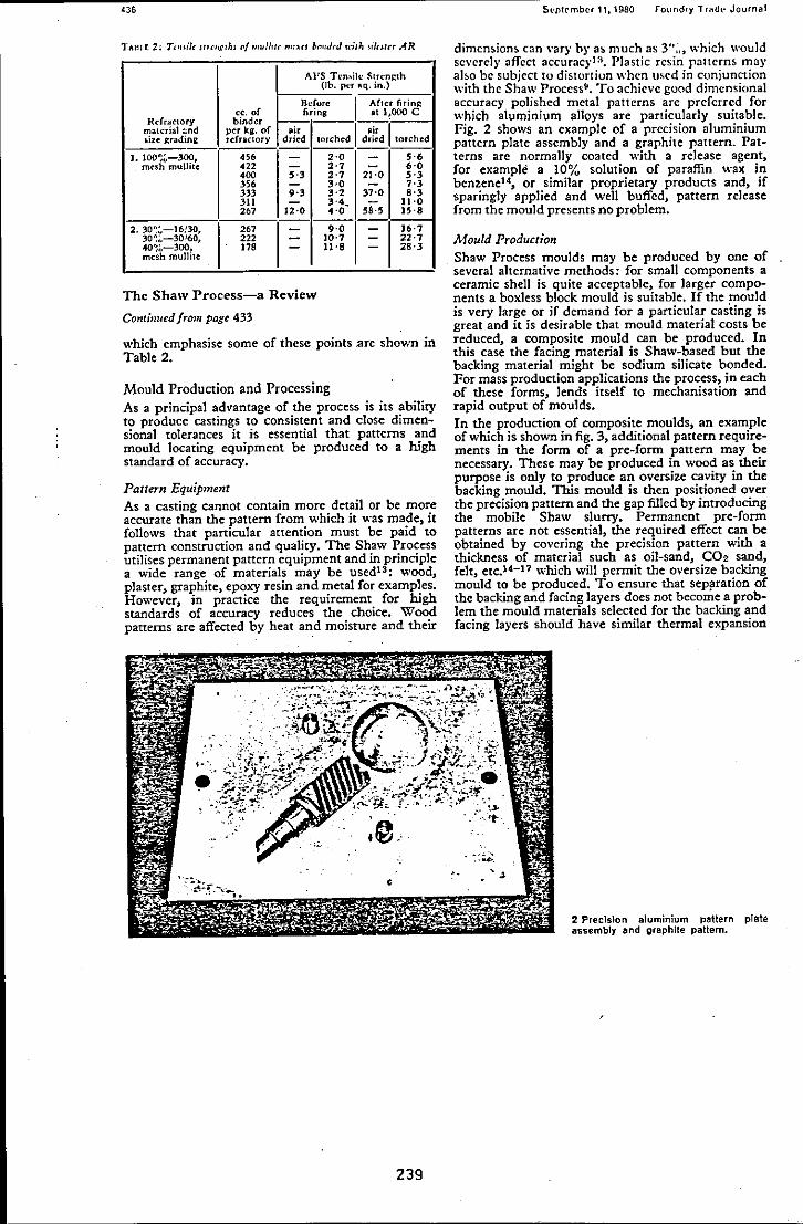
'3.
AI'S Ten_ile f\(rcn~lh (lb. pcr ,;q. in.)
cc. of Before: 1 Af1<:r firing
Rdnu:"lOry binder ~r~ .tl!OOOC
material ~nd per kg. of .i, I ,. I .izC' grading refractor), dried lorched dried lorched
J. l00';~-300, ". - 2'0 - 5'6 m('5h mullite 422 - 2'7 - 6'0
400 5·3 2·7 21·0 5'3 356 - 3,'0 - 7·3 333 9·3 3·2 37·0 .'3 311 - 3'4~ - 11·0 267 12·0 4'0 58-5 15·8
2.30'::"-]6/30, 267 - 9·0
I - J6·7
30~;'-30160. 222 - 10·7 - 22·7 40%-300, 17. - 11'8 - 28·3 mesh mullitc:
The Shaw Process-a Review
Continued from page 433
which emphasise some of these points .are shown in Table 2.
Mould Production and Processing As a principal advantage of the process is its ability to produce castings to consistent and close dimensional tolerances it is essential that patterns and mould locating equipment be produced to a high standard of accuracy.
Pattern Equipment As a casting cannot contain more detail or be more accurate than the pattern from which it was made, it follows that particular attention must be paid to pattern construction and quality. The Shaw Process utilises permanent pattern equipment and in principle a wide range of materials may be used13 : wood, plaster, graphite, epoxy resin and metal for examples. However, in practice the requirement for high standards of accuracy reduces the choice. Wood patterns are affected by heat and moisture and their
239
Sl'ptcmbcr 11, 1980 fOllndry TI<ld{" Journal
dimensions can \'ary by as much as 3'";" which would se\'erely affect accuracyl:J. Plastic resin patterns may aho be subject to distortion when w.ed in conjunction with the Shaw Process". To achieve good dimensional accuracy polished metal patterns arc preferred for which aluminium alloys are particularly suitable. Fig. 2 shows an example of a precision aluminium pattern plate assembly and a graphite pattern. Patterns arc normally coated with a release agent, for example a 10% solution of paraffin wax in benzene14, or similar proprietary products and, if sparingly applied and well buffed, pattern release from the mould presents no problem.
Mould Production Shaw Process moulds may be produced by one of several alternative methods: for small components a ceramic shell is quite acceptable, for larger components a boxless block mould js suitable. If the mou1d is very large or jf demand for a particular casting is great and it is desirable that mould material costs be reduced, a composite mould can be produced. In this case the facing material is Shaw-based but the backing material might be sodium silicate bonded. For mass production applications the process, in each of these forms, lends itself to mechanisation and rapid output of moulds. In the production of composite moulds, an example of which is shown in fig. 3, additional pattern requirements in the form of a pre-form pattern may be necessary. These may be produced in wood as their purpose is only to produce an oversjze cavity in the backing mould. This mould is then positioned over the precision pattern and the gap filled by introducing the mobile Shaw slurry. Permanent pre-form patterns are not essential, the required effect can be obtained by covering the precision pattern with a thickness of material such as oil-sand, C02 sand, felt, etc.14- 17 which will permit the oversize backing mould to be produced. To ensure that sep!lration of the backing and facing layers does not become a problem the mould materials selected for the backing and facing layers should have similar thermal expansion
2 Precision aluminium pattern plate assembly and graphite pattern.
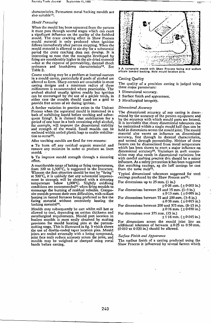
Fourodry TrCldfJ Journal September 11, 1980
characteristics. Permanent metal backing moulds are also suitablel fI.
Afoflld Proccss,",zg
When the mould has been separated from the pattern it must pass through several stages which can ex en a significant influence on the quality of the finished mould. The craze cracking effect in Shaw Process mould material is only produced when ignition follows immediately after pattern stripping. When the mould material is allowed to air-dry for a substantial period the craze cracking does not develop. It is interesting to note that the strengths -devCloped by firing are considerably higher in the air-dried material -but at the expense of permeability, thermal shock resistance and breakdown characteristics19• See Table 2. Coarse cracking may be a problem at internal corners in a mould cavity, particularly if pools of alcohol are allowed to form. Sharp corners are unsuitable in most casting designs and a minimum radius of three millimetres is recommended where practicable. The evolved alcohol usually ignites readily but ignition can be encouraged by the use of a gas/air torch, in either case the moulds should stand on a grid to provide free access of air during ignition. A further variation in practice exists in the Unicast Process when the separated mould is immersed in a bath of stabilising liquid before torching and subsequent firing2. It is claimed that stabilisation for a period of one hour in a bath containing ethyl alcohol, for example, will improve the dimensional stability and strength of the mould. Small moulds can be enclosed within sealed plastic bags to enable stabilisation to occur20•
Mter torching moulds are fired for two reasons: a To burn oft' any residual organic material and remove any moisture in order to produce an inert mould .. b To improve mould strength through a sinterin'g effect. A considerable range of baking or firing temperatures, from 300 to 1,300":>C, is suggested in the literature. Whereas the first objective should be met by "firingU
at 500~C, it is unlikely that any substantial improvement in strength will be obtained with a sintering temperature below 1,OOO°C. Slightly oxidising conditions are reconunended21 when firing moulds to encourage the burning of residual volatiles. Composite moulds present their own difficulties, with radiant heating in tunnel furnaces being preferred to fire the facing material without excessively heating the backing materiaI2!. Moulds may subsequently be cast whilst still hot or allowed to cool, depending on section thickness and metallurgical requirements. Mould part location in boxless moulds is most easily obtained by making provision for mould locating pins at the panemmaking stage. This is illustrated in fig. 3 which shows the use of double-ended taper location pins. Mould joints are sealed externally with a luting compound, joint face seals reduce accuracy across the joint, and moulds may be weighted or clamped using metal bands before casting.
240
3 A composIte mould with Shaw Process facing and sodium silicate bonded backing. Note moutd location pins.
Casting Quality
The quality of a preCISIon casting is judged using three major parameters: 1 Dimensional accuracy. 2 Surface finish and appearance. 3 Metallurgical integrity.
Dimensional Accuracy
The dimensional accuracy of any casting is deter-, mined by the accuracy of the pattern equipment and by the accuracy with which mould pans are located. It is inevitable that closer dimensional tolerances can be maintained within a single mould half than can be held in dimensions across the mould joint. The mould material also exens an influence on dimensional accuracy, first through its thermal characteristics, and second through permeability. Neither of these factors can be disassociated from metal temperature which has been -shown to exen a major influence on dimensional accuracy!3. Variations in melt composition may also result in dimensional variations but with careful melting practice this should be a minor influence. As a safety precaution it has been suggested that matching castings, eg die half castings be cast from the same melt24•
Typical dimensional tolerances suggested for steel castings produced by the Shaw Process are25 : For dimensions up to 25 mm. (I in.)
± 0-08 mm. (± 0-003 in.) For dimensions between 25 and 75 mm. (1-3 in.)
±0'13 mm. (±0·005 in.) For dimensions between 75 and 200 mm. (3-S in.)
±0'38 mm. (±0'015 in.) For dimensions between 200 and 375 mm. (8-15 in.)
± 0-76 mm. (± 0-030 in.) For dimensions over 375 mm. (15 in.)
± 1-14 mm. (±0'045 in.) For dimensions across the mould joint line an additional tolerance of between ± 0·25 to 0,50 mm. (0-010 to 0-020 in.) should be allowed.
Surface Finish and Appearance The surface finish of a casting produced using the Shaw Process is influenced by several factors which
THE SUA\\, PHOr:[~S-A Rt:\'ltW
include refractory grading, metal and mould temperature, and metal/mould reactions considered in the following section.The finer the grade of refractory filler used in the refractory aggregate the better should he the surface finish. Preheated moulds and high casting temperature arc likely to reduce the quality of surface finish 2G. It is possible to obtain surface finish values in the region of two micrometres (BO microinches) c1a for steel castings, better for non-ferrous alloys, which compar~s with five to ten micrometres (200-400 microinches) c1a for sand castings.
Heavily oxidised surfaces reduce both dimensional accuracy and the quality of surface finish directly and through the requirement for abrasive shot blasting. The use of inert gas atmospheres to minimise these effects can be worthwhile.
Metallurg,'cal Considerations The nature of the Shaw Process mould material results in relatively slow cooling of the metal in comparison with other casting processes. This can cause a coarse grain structure which may be unacceptable in cenain castings' applications; it can be countered by grain refining additions. The slow cooling is in pan responsible for decarburisation and surface oxidation in steel castings2? In steels containing chromium the surface may be further affected by pitting28.
Decarburisation has been shown to be a function of the time that the casting remains at an elevated temperature, that is above 875°C2? In practice the severity of the probJem can be reduced by one of several methods which include: hexamethylene tetra mine placed on the exposed surface of the metal whep the mould is enclosed within a container~9, a reducing gas atmosphere3o, or most effectively by a vacuum treatment to remove air from the mould followed by back filling with an inert gas2;. The occurrence of pitting has been shown to be associated with decarburisation28• The two phenomena are caused by carbon monoxide formation. Carbon in the metal reacts with oxygen from the mould atmosphere and the silica which provides the mould bond. This results in decarburisation and the carbon monoxide bubbles deform the casting surface. This implies that it may not be possible to eliminate decarburisation entirely because oxygen will always be present in the silica which provides the bond.
It has been suggested that casting surface characteristics can be altered by passing a gas through the mould material as a steel casting is cooled. By using ammonia31 a nitrided surface can be developed and a carburised surface produced by using a carbon rich atmosphere21 •
Acknowledgements
The author is working in association with Dr. A. A. Das to whom a Science Research Council grant was
241
a\'I.'ardcd to invcstigate the optimisation of material!<. and mcthod!l. in the production of cast dies.
The author would like to thank Professor R. J. Sury, head of the Department of Engineering Production, Loughborough Unh'crsity of Technology, for the provision of facilities and permission to publish this article.
REFERENCES 1 Shaw, C. FOUJ<DRY TRADE JOURNAL, 1946, 78
(1534), 31 2 Greenwood, R. American Patent 3,172,176. 3 Lubalin, I. and Christcnsen, R. J. Modern Casting,
1960, 38 (4), 83. 4 Emblem, H. F. Trans. and J. Br. Ceramic Soc.,
1975, 74 (23), 660. 5 Jones, K. et al. Tin and its Uses, 1979, 119, 10. 6 Emblem, H. G. FOtTh;"DRY TRADE JOURNAL, 1972,
132 (2884), 379. 7 Lawrence, W. G. Modern Casting, 1960, 38 (2),
J09. S Wales, W. F. Trans. AFS, 1973,81,249. 9 Paterson, S. SAE Trans., 1967, 75, paper 660645,
263. 10 Kingery, W. D. Introduction to Ceramics. Wiley,
London, 1976. 11 Budwonh, D. W. An Introduction to Ceramic
Science. Pergamon, Oxford, 1970. -12 Russell, C. J. MSc Project, Loughborough Uni
versity of Technology, March 1980. 13 Butler, M. J. British Plastics, 1970,43 (6), 144. 14 Balinskii, V. R. et al. Russian Castings Production,
1972,421. 15 Winter, D. B. FOUh."DRY TRADE JOURNAL, 1964,
116 (2474), 427. 16 Dittrich, W. Giesserei, 1972,59 (8), 239. 17 Dunlop, A. American Patent, 2,931,081. 18 Lubalin, I. J. American Patent, 3,242,539. 19 Shaw, N. American Patent, 2,795,022. 20 Scan, R. K. American Patent, 3,213,497. 21 Olsen, C. F. ASTME Technical Paper, CM69-
235, 1969. 22 Prasad, J. S. and Watmough, T. Trans. AFS,
1969, 77, 289. 23 Szende, Gy. Ban),. esKoh. Lapok (Ontode), 1976,
27 (3), English translation BISI14700. 24 Bazzano, E. Gaslings, 1970, 16 (5), 24. 25 M etals Handbook, 5B, 262. American Society for
Metals, Ohio. 26 Fominyk, I. P. et al. Russian Casrings Production,
1976,467. 27 Doremus, G. E. and Loper, C. R. Trans. AFS,
1970, 78, 338. 28 Yardmici, G., Fischer, F. and Klein, E. Proc. 4th
If),orldConference on Im'esrment Casting, June 1976. 29 Shaw, C. American Patent 2,935,722. 30 Lubalin, I. Cast Forging Dies. ASlME, Hanford,
Connecticut, 1965. 31 Pikman, A. A. et al. Russian Caslillgs Prbduclion,
1976,253.

· I ,
I
,