Embed Size (px)
Citation preview

2011
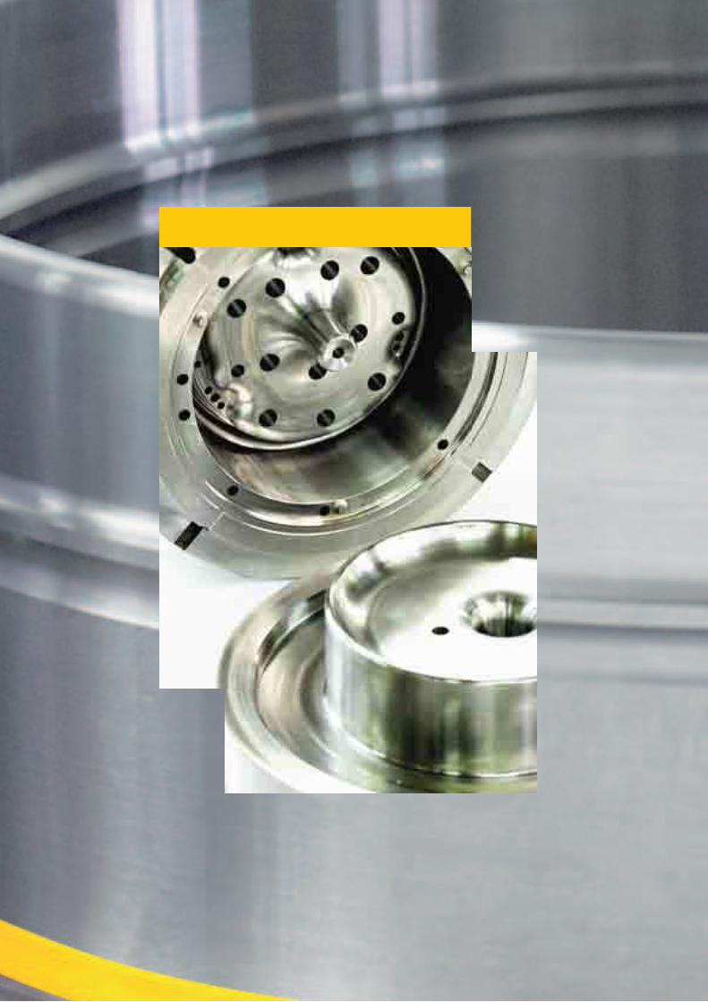
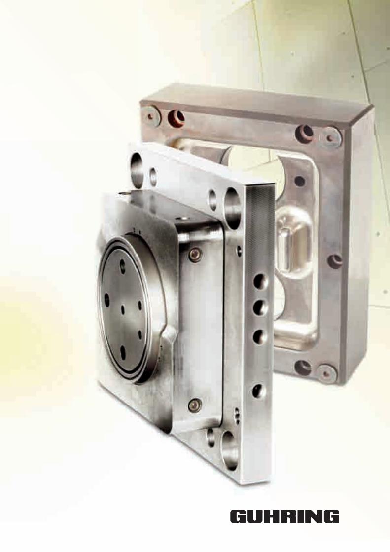
Tools for the mould and die industry
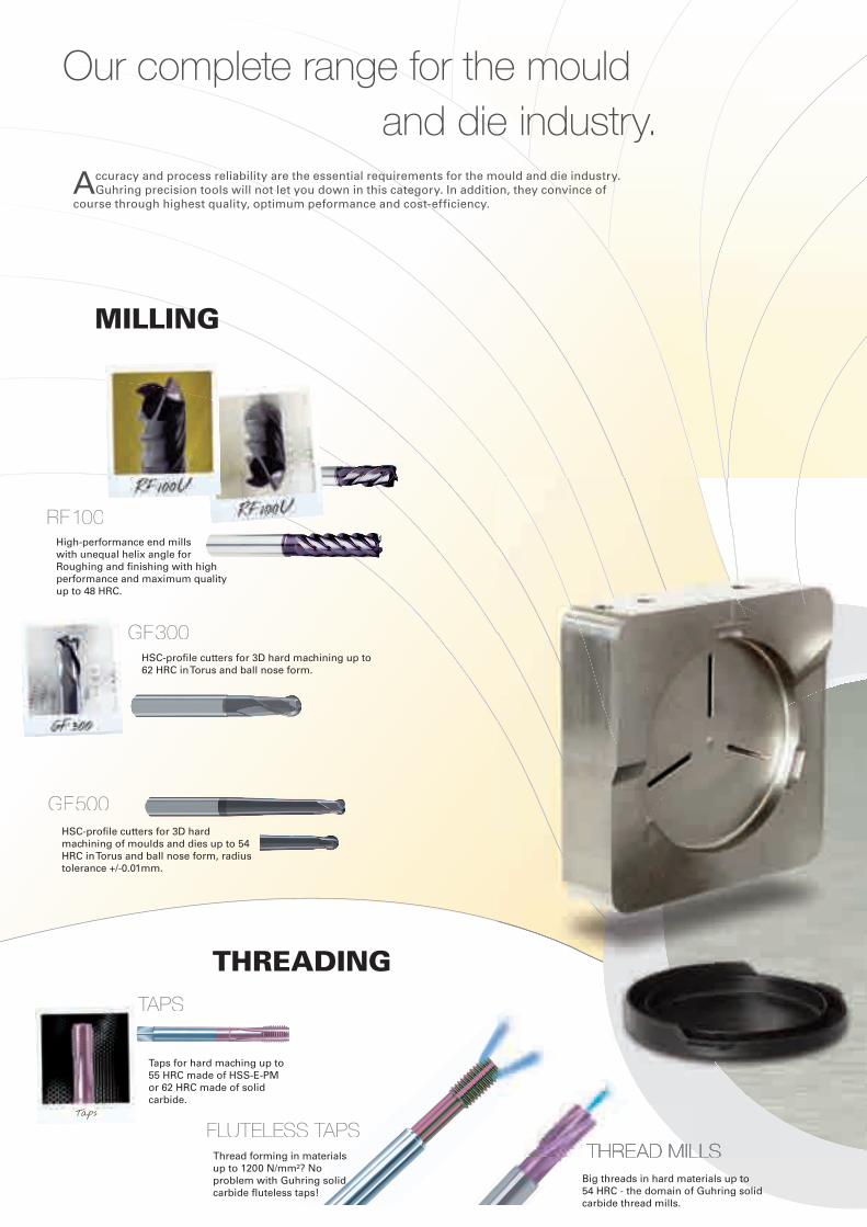
Accuracy and process reliability are the essential requirements for the mould and die industry. Guhring precision tools will not let you down in this category. In addition, they convince of
course through highest quality, optimum peformance and cost-efficiency.
and die industry.Our complete range for the mould
threadinG
millinG
HSC-profile cutters for 3D hard machining of moulds and dies up to 54 HRC in Torus and ball nose form, radius tolerance +/-0.01mm.
HSC-profile cutters for 3D hard machining up to 62 HRC in Torus and ball nose form.
Taps for hard maching up to 55 HRC made of HSS-E-PM or 62 HRC made of solid carbide.
Big threads in hard materials up to 54 HRC - the domain of Guhring solid carbide thread mills.
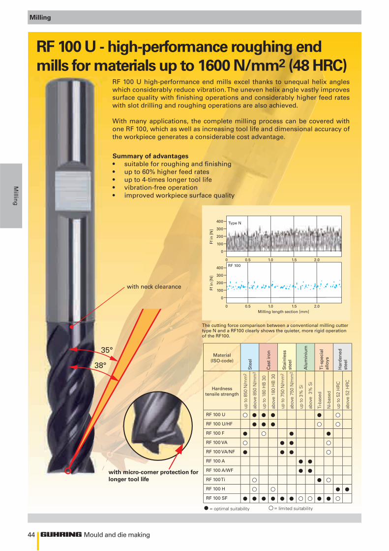
High-performance end mills with unequal helix angle for Roughing and finishing with high performance and maximum quality up to 48 HRC.
Taps
fluteless tapsthread millsthread millsthread millsthread millsthread millsThread forming in materials
up to 1200 N/mm²? No problem with Guhring solid carbide fluteless taps!
RF 100
GF 500
GF 300
Taps
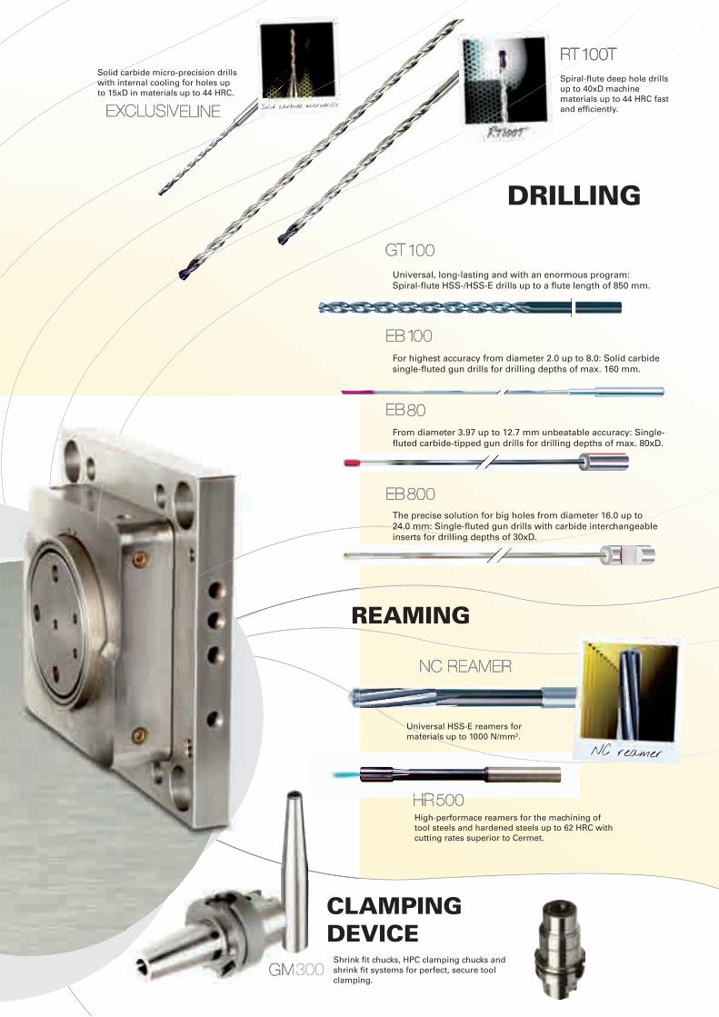
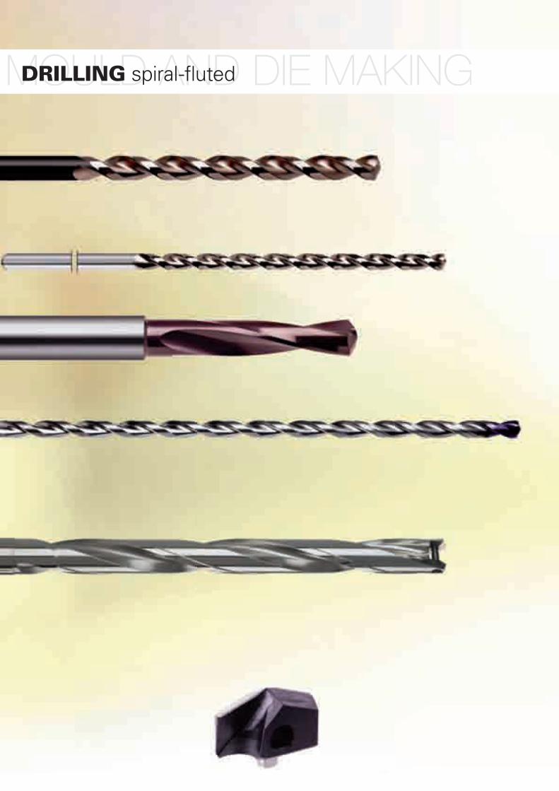
and die industry.Solid carbide micro-precision drills with internal cooling for holes up to 15xD in materials up to 44 HRC.
Spiral-flute deep hole drills up to 40xD machine materials up to 44 HRC fast and efficiently.
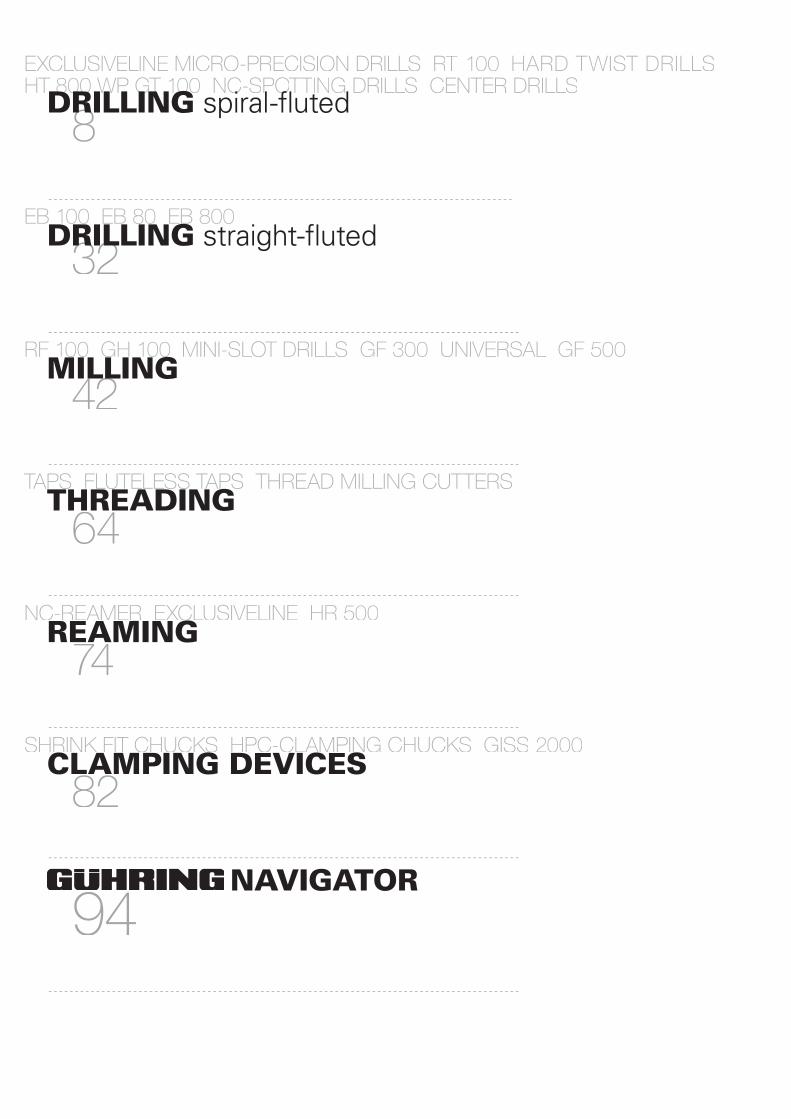
drillinG
High-performace reamers for the machining of tool steels and hardened steels up to 62 HRC with cutting rates superior to Cermet.
Universal HSS-E reamers for materials up to 1000 N/mm².
Shrink fit chucks, HPC clamping chucks and shrink fit systems for perfect, secure tool clamping.
Universal, long-lasting and with an enormous program: Spiral-flute HSS-/HSS-E drills up to a flute length of 850 mm.
For highest accuracy from diameter 2.0 up to 8.0: Solid carbide single-fluted gun drills for drilling depths of max. 160 mm.
From diameter 3.97 up to 12.7 mm unbeatable accuracy: Single-fluted carbide-tipped gun drills for drilling depths of max. 80xD.
The precise solution for big holes from diameter 16.0 up to 24.0 mm: Single-fluted gun drills with carbide interchangeable inserts for drilling depths of 30xD.
GGt t GGt GG 100100
eeb 1b 10000
EEb b 8080
EEb b 800800
Gm m 300
rrrrrt t t t t t t t t t 100t100t100t100t100t100t100t100t100t100t
ExclusivExclusivEElinlinEE
hhhhr r r r 500500500500
nc reamernc reamer
reaminG
clampinG device
NC reamer
Solid carbide microdrills
4
>Ø2,36
Mould and die making
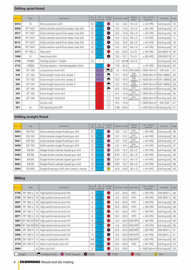
Drilling spiral-fluted
Guh. no. Type Description Coo-ling
Tool material
Surface finish Diameter range Drilling
depthmax. material
hardness Standard Page
6412 N Micro-precision drill IC Solid carbide 1.4 - 3.0 15 x D < 44 HRC Guhring std. 13
6509 RT 100 T Solid carbide spiral-flute deep hole drill IC Solid carbide 3.0 - 14.0 15 x D < 44 HRC Guhring std. 15
6511 RT 100 T Solid carbide spiral-flute deep hole drill IC Solid carbide 3.0 - 14.0 20 x D < 44 HRC Guhring std. 16
6512 RT 100 T Solid carbide spiral-flute deep hole drill IC Solid carbide 3.0 - 12.0 25 x D < 44 HRC Guhring std. 17
6513 RT 100 T Solid carbide spiral-flute deep hole drill IC Solid carbide 3.0 - 10.0 30 x D < 44 HRC Guhring std. 18
6514 RT 100 T Solid carbide spiral-flute deep hole drill IC Solid carbide 3.0 - 8.0 40 x D < 44 HRC Guhring std. 19
2477 RT 100 U Ratio drill IC Solid carbide 3.0 - 20.0 3 x D < 44 HRC DIN 6537 K 20
1946 H Hard twist drill - Solid carbide 2.6 - 14.1 3 x D < 62 HRC DIN 6537 K 21
4110 HT800 Tooling system - holder IC - - 11.0 -25.99 10 x D - Guhring std. 23
4112 HT800 Tooling system - interchangeable insert Solid carbide 11.0 - 25.5 - < 44 HRC Guhring std. 25
336 GT 100 Long series twist drill - HSCO 1.0 - 16.0 DIN 340 < 1000 N/mm² DIN 340 27
618 GT 100 Extra length twist drill, series 1 - HSCO 2.7 - 10.0 DIN 1869/1 < 1000 N/mm² DIN 1869/1 28
619 GT 100 Extra length twist drill, series 2 - HSCO 3.0 - 10.0 DIN 1869/2 < 1000 N/mm² DIN 1869/2 28
504 GT 100 Extra length twist drill, series 3 - HSS 2.5 - 12.0 DIN 1869/3 < 1000 N/mm² DIN 1869/3 29
242 GT 100 Extra length twist drill - HSS 6.0 - 12.0 max. 400 mm < 1000 N/mm² Guhring std. 29
243 GT 100 Extra length twist drill - HSS 8.0 - 12.0 max. 650 mm < 1000 N/mm² Guhring std. 30
244 GT 100 Extra length twist drill - HSS 10.0 - 12.0 max. 850 mm < 1000 N/mm² Guhring std. 30
581 - Center drill - HSS 0.5 - 12.5 - < 1000 N/mm² DIN 333 31
557 N NC-spotting drill 90° - HSS 2.95 - 25.4 - < 1000 N/mm² Guhring std. 31
Drilling straight-fluted
Guh. no. Type Description Coo-ling
Tool material
Surface finish Diameter range Drilling
depthmax. material
hardness Standard Page
5632 EB 100 Solid carbide single-fluted gun drill IC Solid carbide 2.0 - 3.2 max.
45 mm < 44 HRC Guhring std. 36
5633 EB 100 Solid carbide single-fluted gun drill IC Solid carbide 2.0 - 5.0 max.
80 mm < 44 HRC Guhring std. 36
5637 EB 100 Solid carbide single-fluted gun drill IC Solid carbide 2.0 - 5.0 max.
120 mm < 44 HRC Guhring std. 37
5638 EB 100 Solid carbide single-fluted gun drill IC Solid carbide 2.0 - 8.0 max.
160 mm < 44 HRC Guhring std. 37
5639 EB 80 Single-fluted carbide tipped gun drill IC Carbide 3.97 - 12.7 20 x D < 44 HRC Guhring std. 38
5640 EB 80 Single-fluted carbide tipped gun drill IC Carbide 3.97 - 12.7 30 x D < 44 HRC Guhring std. 38
5641 EB 80 Single-fluted carbide tipped gun drill IC Carbide 3.97 - 12.7 40 x D < 44 HRC Guhring std. 39
5642 EB 80 Single-fluted carbide tipped gun drill IC Carbide 3.97 - 12.7 80 x D < 44 HRC Guhring std. 39
5644 EB 800 Single-fluted gun drill with interch. inserts IC Carbide plates 16.0 - 24.0 30 x D < 44 HRC Guhring std. 40
Milling
Guh. no. Type Description No. of teeth
Tool material
Surface finish Diameter range Application max. material
hardness Standard Page
3736 RF 100 U N High-performance end mill 4 Solid carbide 4.0 - 25.0 HPC < 48 HRC DIN 6527 L 48
3732 RF 100 U N High-performance end mill 4 Solid carbide 4.0 - 25.0 HPC < 48 HRC DIN 6527 L 48
3837 RF 100 U N High-performance end mill 4 Solid carbide 6.0 - 20.0 HPC < 48 HRC Guhring std. 49
3838 RF 100 U N High-performance end mill 4 Solid carbide 6.0 - 20.0 HPC < 48 HRC Guhring std. 49
3839 RF 100 U N High-performance end mill 4 Solid carbide 6.0 - 20.0 HPC < 48 HRC Guhring std. 49
3871 RF 100 U N High-performance end mill 4 Solid carbide 6.0 - 20.0 HPC < 48 HRC Guhring std. 49
3897 RF 100 S/F NH High-performance end mill 5 Solid carbide 4.0 - 20.0 HSC/HPC < 48 HRC Guhring std. 50
3898 RF 100 S/F NH High-performance end mill 5 Solid carbide 4.0 - 20.0 HSC/HPC < 48 HRC Guhring std. 50
3895 RF 100 H H High-performance end mill 4 Solid carbide 6.0 - 20.0 HSC/HPC < 62 HRC DIN 6527 L 51
3896 RF 100 H H High-performance end mill 4 Solid carbide 6.0 - 20.0 HSC/HPC < 62 HRC DIN 6527 L 51
3715 GH 100 H H Hard multi-tooth end mill 6-8 Solid carbide 3.0 - 20.0 HSC/HPC < 62 HRC Guhring std. 52
3716 GH 100 H H Hard multi-tooth end mill 6-8 Solid carbide 6.0 - 20.0 HSC < 62 HRC Guhring std. 53
3684 - N Mini slot drill 3 Solid carbide 0.3 - 20.0 - < 1000 N/mm² Guhring std. 53
bright nitrided lands TiAlN SuperA TiAlN TiCN FIRE TiN
5
Mould and die making
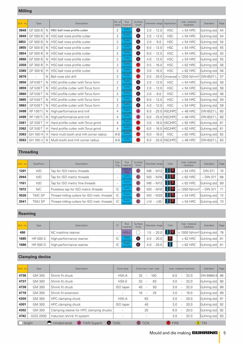
Milling
Guh. no. Type Description No. of teeth
Tool material
Surface finish Diameter range Application max. material
hardness Standard Page
3848 GF 500 B N HSC-ball nose profile cutter 2 Solid carbide 2.0 - 12.0 HSC < 54 HRC Guhring std. 54
3849 GF 500 B N HSC-ball nose profile cutter 2 Solid carbide 2.0 - 12.0 HSC < 54 HRC Guhring std. 54
3853 GF 500 B N HSC-ball nose profile cutter 2 Solid carbide 2.0 - 8.0 HSC < 54 HRC Guhring std. 54
3855 GF 500 B N HSC-ball nose profile cutter 2 Solid carbide 6.0 - 12.0 HSC < 54 HRC Guhring std. 55
3854 GF 500 B N HSC-ball nose profile cutter 2 Solid carbide 6.0 - 12.0 HSC < 54 HRC Guhring std. 55
3866 GF 500 B N HSC-ball nose profile cutter 2 Solid carbide 4.0 - 12.0 HSC < 54 HRC Guhring std. 55
3359 GF 300 B H HSC-ball nose profile cutter 2 Solid carbide 0.5 - 16.0 HSC < 62 HRC Guhring std. 56
3360 GF 300 B H HSC-ball nose profile cutter 2 Solid carbide 3.0 - 16.0 HSC < 62 HRC Guhring std. 56
3679 - N Ball nose slot drill 2 Solid carbide 0.5 - 20.0 Universal < 1200 N/mm² DIN 6527 L 57
3856 GF 500 T N HSC-profile cutter with Torus form 2 Solid carbide 2.0 - 12.0 HSC < 54 HRC Guhring std. 58
3859 GF 500 T N HSC-profile cutter with Torus form 2 Solid carbide 2.0 - 12.0 HSC < 54 HRC Guhring std. 58
3860 GF 500 T N HSC-profile cutter with Torus form 2 Solid carbide 2.0 - 8.0 HSC < 54 HRC Guhring std. 58
3865 GF 500 T N HSC-profile cutter with Torus form 2 Solid carbide 6.0 - 12.0 HSC < 54 HRC Guhring std. 59
3863 GF 500 T N HSC-profile cutter with Torus form 2 Solid carbide 4.0 - 12.0 HSC < 54 HRC Guhring std. 59
3498 RF 100 Ti N High-performance end mill 4 Solid carbide 6.0 - 25.0 HSC/HPC < 48 HRC DIN 6527 L 60
3499 RF 100 Ti N High-performance end mill 4 Solid carbide 6.0 - 25.0 HSC/HPC < 48 HRC DIN 6527 L 60
3361 GF 300 T H Hard profile cutter with Torus grind 4 Solid carbide 3.0 - 16.0 HSC/HPC < 62 HRC Guhring std. 61
3362 GF 300 T H Hard profile cutter with Torus grind 4 Solid carbide 6.0 - 16.0 HSC/HPC < 62 HRC Guhring std. 61
3363 GH 100 H H Hard multi-tooth end mill corner radius 6-8 Solid carbide 6.0 - 16.0 HSC < 62 HRC Guhring std. 62
3563 GH 100 U N Multi-tooth end mill corner radius 6-8 Solid carbide 6.0 - 20.0 HSC/HPC < 48 HRC DIN 6527 L 63
Threading
Guh. no. Type/Form Description Coo-ling
Tool material
Surface finish Diameter range Hole max. material
hardness Standard Page
1201 H/D Tap for ISO metric threads - HSS-E PM M6 - M12 < 54 HRC DIN 371 70
2944 H/D Tap for ISO metric threads - Solid carbide M3 - M16 < 62 HRC ~ DIN 371 68
1161 H/D Tap for ISO metric fine threads - Solid carbide M6 - M12 < 62 HRC Guhring std. 69
1972 N/C Fluteless tap for ISO metric threads IC Solid carbide M3 - M10 < 1200 N/mm² ~ DIN 371 71
3526 TMC SP Thread milling cutters for ISO metr. threads IC Solid carbide M3 - M20 < 54 HRC Guhring std. 72
3541 TMU SP Thread milling cutters for ISO metr. threads IC Solid carbide ≥14 - ≥30 < 54 HRC Guhring std. 73
Reaming
Guh. no. Type Description IC Tool material
Surface finish Diameter range Hole max. material
hardness Standard Page
490 - NC machine reamer - HSS-E 1.5 - 20.0 < 1000 N/mm² Guhring std. 78
1685 HR 500 S High-performance reamer IC Solid carbide 4.0 - 20.0 < 62 HRC Guhring std. 81
1686 HR 500 D High-performance reamer IC Solid carbide 4.0 - 20.0 < 62 HRC Guhring std. 81
Clamping device
Guh. no. Type Description Cone type Cone size / nom. size max. material hardness Standard Page
4736 GM 300 Shrink fit chuck HSK-A 32 - 100 6.0 - 32.0 DIN 69882-8 86
4737 GM 300 Shrink fit chuck HSK-E 32 - 63 3.0 - 32.0 Guhring std. 90
4738 GM 300 Shrink fit chuck ISO taper 40 - 50 3.0 - 32.0 Guhring std. 88
4719 GM 300 Shrink fit extension - 16 - 25 3.0 - 16.0 Guhring std. 89
4300 GM 300 HPC clamping chuck HSK-A 63 3.0 - 20.0 Guhring std. 91
4301 GM 300 HPC clamping chuck ISO taper 40 3.0 - 20.0 Guhring std. 92
4302 GM 300 Clamping sleeve for HPC clamping chucks - 20 6.0 - 20.0 Guhring std. 92
4742 GISS 2000 Induction shrink fit system - - 3.0 - 32.0 Guhring std. 93
bright nitrided lands TiAlN SuperA TiAlN TiCN FIRE TiN
32
8
42
64
74
82
94
nc-reamer exclusiveline hr 500reaminG
eb 100 eb 80 eb 800
HT 800 WP gTHT 800 WP gTHT 800 WP g 100 NC-sT 100 NC-sT PoTToTTo iNg drills CeNTer drills ExclusivElinE Micro-PrEcision drills rt 100 Hard twist drills
shrink Fit chucks hpc-clamping chucks giss 2000
drillinG straight-fluted
drillinG spiral-fluted
clampinG devices
rf 100 gh 100 mini-slot drills gf 300 universal gf 500 0 mini-slot drills gf 300 universal gf 500 0millinG
taps fluteless taps thread milling cutters threadinG
naviGator
mould and die makingdrillinG spiral-fluted
10
15 x D
15 x D
20 x D
25 x D
30 x D
40 x D
3 x D
3 x D
10 x D
-
Mould and die making
Drillin
gsp
iral-fluted
Standard Type Tool description Drilling depth Tool material Surface finish Diameter range Guhring
no.Discount
group
Standard rangepage
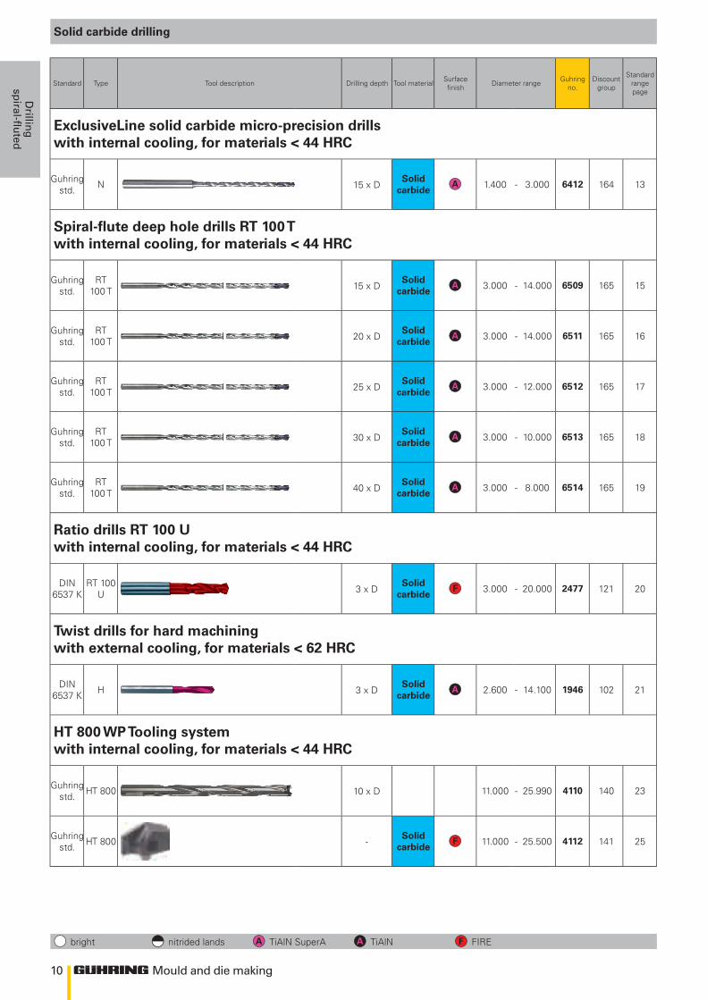
ExclusiveLine solid carbide micro-precision drills with internal cooling, for materials < 44 HRC
Guhring std. N
Solid carbide 1.400 - 3.000 6412 164 13
Spiral-flute deep hole drills RT 100 Twith internal cooling, for materials < 44 HRC
Guhring std.
RT 100 T
Solid carbide 3.000 - 14.000 6509 165 15
Guhring std.
RT 100 T
Solid carbide 3.000 - 14.000 6511 165 16
Guhring std.
RT 100 T
Solid carbide 3.000 - 12.000 6512 165 17
Guhring std.
RT 100 T
Solid carbide 3.000 - 10.000 6513 165 18
Guhring std.
RT 100 T
Solid carbide 3.000 - 8.000 6514 165 19
Ratio drills RT 100 Uwith internal cooling, for materials < 44 HRC
DIN 6537 K
RT 100 U
Solid carbide 3.000 - 20.000 2477 121 20
Twist drills for hard machiningwith external cooling, for materials < 62 HRC
DIN 6537 K H
Solid carbide 2.600 - 14.100 1946 102 21
HT 800 WP Tooling systemwith internal cooling, for materials < 44 HRC
Guhring std. HT 800 11.000 - 25.990 4110 140 23
Guhring std. HT 800
Solid carbide 11.000 - 25.500 4112 141 25
Solid carbide drilling
bright nitrided lands TiAlN SuperA TiAlN FIRE
11
>Ø2,36
Mould and die making
Dri
llin
gsp
iral
-flu
ted
Standard Type Tool description Drilling depth Tool material Surface finish Diameter range Guhring
no.Discount
group
Standard rangepage
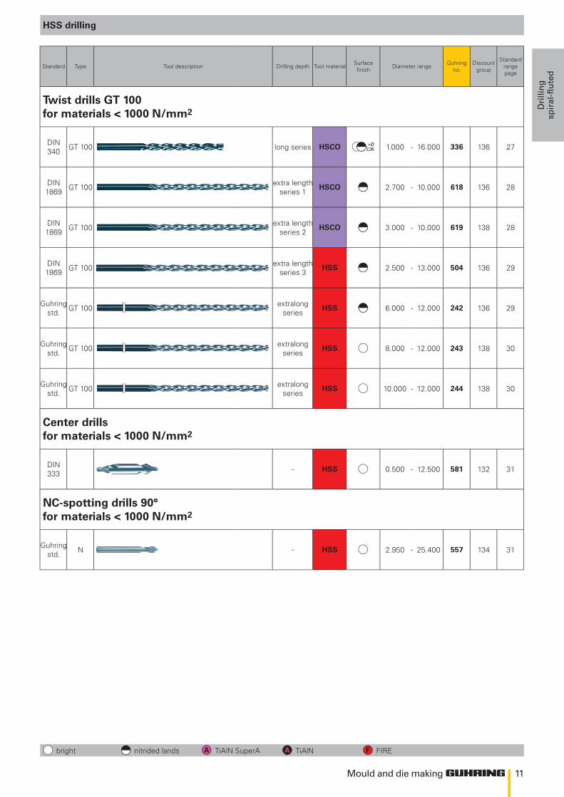
Twist drills GT 100for materials < 1000 N/mm2
DIN 340 GT 100 long series HSCO 1.000 - 16.000 336 136 27
DIN 1869 GT 100 extra length
series 1HSCO 2.700 - 10.000 618 136 28
DIN 1869 GT 100 extra length
series 2HSCO 3.000 - 10.000 619 138 28
DIN 1869 GT 100 extra length
series 3HSS 2.500 - 13.000 504 136 29
Guhring std. GT 100 extralong
seriesHSS 6.000 - 12.000 242 136 29
Guhring std. GT 100 extralong
seriesHSS 8.000 - 12.000 243 138 30
Guhring std. GT 100 extralong
seriesHSS 10.000 - 12.000 244 138 30
Center drillsfor materials < 1000 N/mm2
DIN 333 - HSS 0.500 - 12.500 581 132 31
NC-spotting drills 90°for materials < 1000 N/mm2
Guhring std. N - HSS 2.950 - 25.400 557 134 31
HSS drilling
bright nitrided lands TiAlN SuperA TiAlN FIRE
12 Mould and die making
Drillin
gsp
iral-fluted
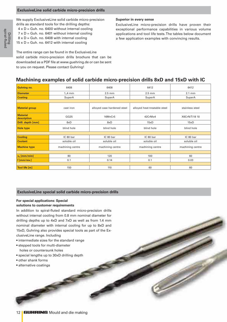
ExclusiveLine solid carbide micro-precision drills
ExclusiveLine micro-precision drills have proven their exceptional performance capabilities in various volume applications and tool life tests. The tables below document a few application examples with convincing results.
For special applications: Specialsolutions to customer requirements
In addition to spiral-fluted standard micro-precision drills without internal cooling from 0.8 mm nominal diameter for drilling depths up to 4xD and 7xD as well as from 1.4 mm nominal diameter with internal cooling for up to 8xD and 15xD, Guhring also provides special tools as part of the Ex-clusiveLine range. Including• intermediate sizes for the standard range• stepped tools for multi-diameter
holes or countersunk holes• special lengths up to 30xD drilling depth• other shank forms• alternative coatings
Superior in every senseWe supply ExclusiveLine solid carbide micro-precision drills as standard tools for the drilling depths: 4 x D = Guh. no. 6400 without internal cooling 7 x D = Guh. no. 6401 without internal cooling 8 x D = Guh. no. 6408 with internal cooling15 x D = Guh. no. 6412 with internal cooling
The entire range can be found in the ExclusiveLinesolid carbide micro-precision drills brochure that can be downloaded as a PDF file at www.guehring.de or can be sent to you on request. Please contact Guhring!
ExclusiveLine special solid carbide micro-precision drills
Guhring no. 6408 6408 6412 6412
Diameter 1.,4 mm 2.5 mm 2.5 mm 2.1 mm
Coating SuperA SuperA SuperA SuperA
Material group cast iron alloyed case hardened steel alloyed heat-treatable steel stainless steel
Material description GG25 16MnCr5 42CrMo4 X6CrNiTi18 10
Drill. depth [mm] 8xD 8xD 15xD 15xD
Hole type blind hole blind hole blind hole blind hole
Cooling IC 80 bar IC 80 bar IC 80 bar IC 80 bar
Coolant soluble oil soluble oil soluble oil soluble oil
Machine type machining centre machining centre machining centre machining centre
vc [mm/min] 80 120 100 60
f [mm/rev.] 0.1 0.14 0.1 0.03
Tool life [m] 150 110 60 60
Machining examples of solid carbide micro-precision drills 8xD and 15xD with IC
13
l1
d1
l2
d2
140°
135°
~0,01
# 6400 Tol. m7
# 6412 Tol. h7
Mould and die making
Dri
llin
gsp
iral
-flu
ted
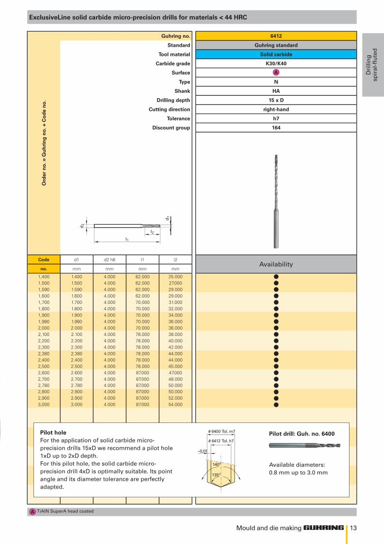
ExclusiveLine solid carbide micro-precision drills for materials < 44 HRC
Ord
er n
o. =
Gu
hri
ng
no.
+ C
od
e n
o.Guhring no. 6412
Standard Guhring standard
Tool material Solid carbide
Carbide grade K30/K40
Surface
Type N
Shank HA
Drilling depth 15 x D
Cutting direction right-hand
Tolerance h7
Discount group 164
Code d1 d2 h6 l1 l2Availability
no. mm mm mm mm
1,400 1.400 4.000 62.000 25.0001,500 1.500 4.000 62.000 27.0001,590 1.590 4.000 62.000 29.0001,600 1.600 4.000 62.000 29.0001,700 1.700 4.000 70.000 31.0001,800 1.800 4.000 70.000 32.0001,900 1.900 4.000 70.000 34.0001,980 1.980 4.000 70.000 36.0002,000 2.000 4.000 70.000 36.0002,100 2.100 4.000 78.000 38.0002,200 2.200 4.000 78.000 40.0002,300 2.300 4.000 78.000 42.0002,380 2.380 4.000 78.000 44.0002,400 2.400 4.000 78.000 44.0002,500 2.500 4.000 78.000 45.0002,600 2.600 4.000 87.000 47.0002,700 2.700 4.000 87.000 48.0002,780 2.780 4.000 87.000 50.0002,800 2.800 4.000 87.000 50.0002,900 2.900 4.000 87.000 52.0003,000 3.000 4.000 87.000 54.000
TiAlN SuperA head coated
Pilot holeFor the application of solid carbide micro-precision drills 15xD we recommend a pilot hole 1xD up to 2xD depth. For this pilot hole, the solid carbide micro-precision drill 4xD is optimally suitable. Its point angle and its diameter tolerance are perfectly adapted.
Pilot drill: Guh. no. 6400
Available diameters:0.8 mm up to 3.0 mm
lllllllllllllllllllll
14 Mould and die making
Drillin
gsp
iral-fluted
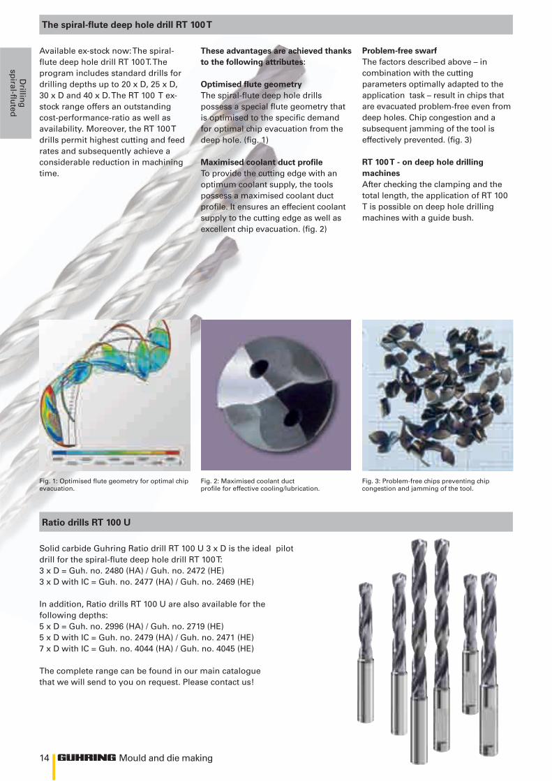
Available ex-stock now: The spiral-flute deep hole drill RT 100 T. The program includes standard drills for drilling depths up to 20 x D, 25 x D, 30 x D and 40 x D. The RT 100 T ex-stock range offers an outstanding cost-performance-ratio as well as availability. Moreover, the RT 100 T drills permit highest cutting and feed rates and subsequently achieve a considerable reduction in machining time.
Fig. 3: Problem-free chips preventing chip congestion and jamming of the tool.
Fig. 1: Optimised flute geometry for optimal chip evacuation.
Fig. 2: Maximised coolant duct profile for effective cooling/lubrication.
The spiral-flute deep hole drill RT 100 T
Solid carbide Guhring Ratio drill RT 100 U 3 x D is the ideal pilot drill for the spiral-flute deep hole drill RT 100 T:3 x D = Guh. no. 2480 (HA) / Guh. no. 2472 (HE)3 x D with IC = Guh. no. 2477 (HA) / Guh. no. 2469 (HE)
In addition, Ratio drills RT 100 U are also available for the following depths:5 x D = Guh. no. 2996 (HA) / Guh. no. 2719 (HE)5 x D with IC = Guh. no. 2479 (HA) / Guh. no. 2471 (HE)7 x D with IC = Guh. no. 4044 (HA) / Guh. no. 4045 (HE)
The complete range can be found in our main catalogue that we will send to you on request. Please contact us!
These advantages are achieved thanks to the following attributes:
Optimised flute geometryThe spiral-flute deep hole drills possess a special flute geometry that is optimised to the specific demand for optimal chip evacuation from the deep hole. (fig. 1)
Maximised coolant duct profileTo provide the cutting edge with an optimum coolant supply, the tools possess a maximised coolant duct profile. It ensures an effecient coolant supply to the cutting edge as well as excellent chip evacuation. (fig. 2)
Problem-free swarfThe factors described above – in combination with the cutting parameters optimally adapted to the application task – result in chips that are evacuated problem-free even from deep holes. Chip congestion and a subsequent jamming of the tool is effectively prevented. (fig. 3)
RT 100 T - on deep hole drilling machinesAfter checking the clamping and the total length, the application of RT 100 T is possible on deep hole drilling machines with a guide bush.
Ratio drills RT 100 U
15
l1
l2l3
d2
d1
140°
135°
~0,01
Tol. m7
Tol. h7RT 100 T
RT 100 U
Mould and die making
Dri
llin
gsp
iral
-flu
ted
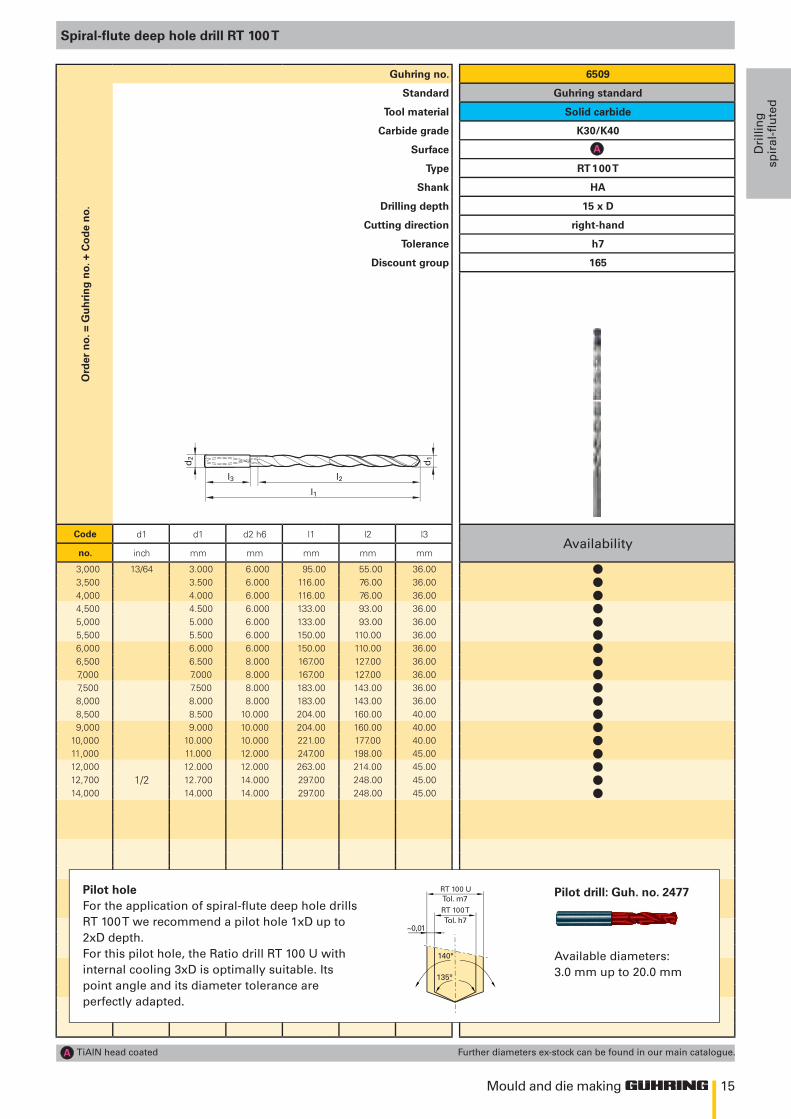
Spiral-flute deep hole drill RT 100 T
Ord
er n
o. =
Gu
hri
ng
no.
+ C
od
e n
o.Guhring no. 6509
Standard Guhring standard
Tool material Solid carbide
Carbide grade K30/K40
Surface
Type RT 100 T
Shank HA
Drilling depth 15 x D
Cutting direction right-hand
Tolerance h7
Discount group 165
Code d1 d1 d2 h6 l1 l2 l3Availability
no. inch mm mm mm mm mm
3,000 13/64 3.000 6.000 95.00 55.00 36.003,500 3.500 6.000 116.00 76.00 36.004,000 4.000 6.000 116.00 76.00 36.004,500 4.500 6.000 133.00 93.00 36.005,000 5.000 6.000 133.00 93.00 36.005,500 5.500 6.000 150.00 110.00 36.006,000 6.000 6.000 150.00 110.00 36.006,500 6.500 8.000 167.00 127.00 36.007,000 7.000 8.000 167.00 127.00 36.007,500 7.500 8.000 183.00 143.00 36.008,000 8.000 8.000 183.00 143.00 36.008,500 8.500 10.000 204.00 160.00 40.009,000 9.000 10.000 204.00 160.00 40.00
10,000 10.000 10.000 221.00 177.00 40.0011,000 11.000 12.000 247.00 198.00 45.0012,000 12.000 12.000 263.00 214.00 45.0012,700 1/2 12.700 14.000 297.00 248.00 45.0014,000 14.000 14.000 297.00 248.00 45.00
TiAlN head coated Further diameters ex-stock can be found in our main catalogue.
Pilot holeFor the application of spiral-flute deep hole drills RT 100 T we recommend a pilot hole 1xD up to 2xD depth. For this pilot hole, the Ratio drill RT 100 U with internal cooling 3xD is optimally suitable. Its point angle and its diameter tolerance are perfectly adapted.
Pilot drill: Guh. no. 2477
Available diameters:3.0 mm up to 20.0 mm
llllllllllllllllll
16
l1
l2l3
d2
d1
140°
135°
~0,01
Tol. m7
Tol. h7RT 100 T
RT 100 U
Mould and die making
Drillin
gsp
iral-fluted
Spiral-flute deep hole drill RT 100 T
Ord
er n
o. =
Gu
hri
ng
no.
+ C
od
e n
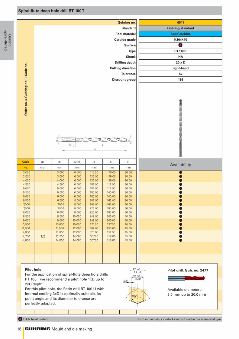
o.Guhring no. 6511
Standard Guhring standard
Tool material Solid carbide
Carbide grade K30/K40
Surface
Type RT 100 T
Shank HA
Drilling depth 20 x D
Cutting direction right-hand
Tolerance h7
Discount group 165
Code d1 d1 d2 h6 l1 l2 l3Availability
no. inch mm mm mm mm mm
3,000 3.000 6.000 110.00 70.00 36.003,500 3.500 6.000 136.00 96.00 36.004,000 4.000 6.000 136.00 96.00 36.004,500 4.500 6.000 158.00 118.00 36.005,000 5.000 6.000 158.00 118.00 36.005,500 5.500 6.000 180.00 140.00 36.006,000 6.000 6.000 180.00 140.00 36.006,500 6.500 8.000 202.00 162.00 36.007,000 7.000 8.000 202.00 162.00 36.007,500 7.500 8.000 223.00 183.00 36.008,000 8.000 8.000 223.00 183.00 36.008,500 8.500 10.000 249.00 205.00 40.009,000 9.000 10.000 249.00 205.00 40.00
10,000 10.000 10.000 271.00 227.00 40.0011,000 11.000 12.000 302.00 253.00 45.0012,000 12.000 12.000 323.00 274.00 45.0012,700 1/2 12.700 14.000 367.00 318.00 45.0014,000 14.000 14.000 367.00 318.00 45.00
TiAlN head coated Further diameters ex-stock can be found in our main catalogue.
Pilot drill: Guh. no. 2477
Available diameters:3.0 mm up to 20.0 mm
Pilot holeFor the application of spiral-flute deep hole drills RT 100 T we recommend a pilot hole 1xD up to 2xD depth. For this pilot hole, the Ratio drill RT 100 U with internal cooling 3xD is optimally suitable. Its point angle and its diameter tolerance are perfectly adapted.
llllllllllllllllll

17
l1
l2l3
d2
d1
140°
135°
~0,01
Tol. m7
Tol. h7RT 100 T
RT 100 U
Mould and die making
Dri
llin
gsp
iral
-flu
ted
Spiral-flute deep hole drill RT 100 T
Ord
er n
o. =
Gu
hri
ng
no.
+ C
od
e n
o.Guhring no. 6512
Standard Guhring standard
Tool material Solid carbide
Carbide grade K30/K40
Surface
Type RT 100 T
Shank HA
Drilling depth 25 x D
Cutting direction right-hand
Tolerance h7
Discount group 165
Code d1 d1 d2 h6 l1 l2 l3Availability
no. inch mm mm mm mm mm
3,000 3.000 6.000 125.00 85.00 36.003,500 3.500 6.000 156.00 116.00 36.004,000 4.000 6.000 156.00 116.00 36.004,500 4.500 6.000 183.00 143.00 36.005,000 5.000 6.000 183.00 143.00 36.005,500 5.500 6.000 210.00 170.00 36.006,000 6.000 6.000 210.00 170.00 36.006,500 6.500 8.000 237.00 197.00 36.007,000 7.000 8.000 237.00 197.00 36.007,500 7.500 8.000 263.00 223.00 36.008,000 8.000 8.000 263.00 223.00 36.008,500 8.500 10.000 294.00 250.00 40.009,000 9.000 10.000 294.00 250.00 40.00
10,000 10.000 10.000 321.00 277.00 40.0011,000 11.000 12.000 359.00 310.00 45.0012,000 12.000 12.000 386.00 337.00 45.00
TiAlN head coated Further diameters ex-stock can be found in our main catalogue.
Pilot drill: Guh. no. 2477
Available diameters:3.0 mm up to 20.0 mm
Pilot holeFor the application of spiral-flute deep hole drills RT 100 T we recommend a pilot hole 1xD up to 2xD depth. For this pilot hole, the Ratio drill RT 100 U with internal cooling 3xD is optimally suitable. Its point angle and its diameter tolerance are perfectly adapted.
llllllllllllllll
18
l1
l2l3
d2
d1
140°
135°
~0,01
Tol. m7
Tol. h7RT 100 T
RT 100 U
Mould and die making
Drillin
gsp
iral-fluted
Spiral-flute deep hole drill RT 100 T
Ord
er n
o. =
Gu
hri
ng
no.
+ C
od
e n
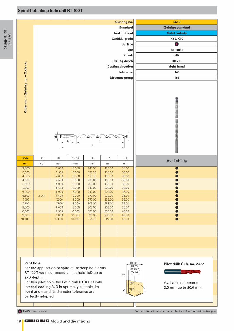
o.Guhring no. 6513
Standard Guhring standard
Tool material Solid carbide
Carbide grade K30/K40
Surface
Type RT 100 T
Shank HA
Drilling depth 30 x D
Cutting direction right-hand
Tolerance h7
Discount group 165
Code d1 d1 d2 h6 l1 l2 l3Availability
no. inch mm mm mm mm mm
3,000 3.000 6.000 140.00 100.00 36.003,500 3.500 6.000 176.00 136.00 36.004,000 4.000 6.000 176.00 136.00 36.004,500 4.500 6.000 208.00 168.00 36.005,000 5.000 6.000 208.00 168.00 36.005,500 5.500 6.000 240.00 200.00 36.006,000 6.000 6.000 240.00 200.00 36.006,500 21/64 6.500 8.000 272.00 232.00 36.007,000 7.000 8.000 272.00 232.00 36.007,500 7.500 8.000 303.00 263.00 36.008,000 8.000 8.000 303.00 263.00 36.008,500 8.500 10.000 339.00 295.00 40.009,000 9.000 10.000 339.00 295.00 40.00
10,000 10.000 10.000 371.00 327.00 40.00
TiAlN head coated Further diameters ex-stock can be found in our main catalogue..
Pilot drill: Guh. no. 2477
Available diameters:3.0 mm up to 20.0 mm
Pilot holeFor the application of spiral-flute deep hole drills RT 100 T we recommend a pilot hole 1xD up to 2xD depth. For this pilot hole, the Ratio drill RT 100 U with internal cooling 3xD is optimally suitable. Its point angle and its diameter tolerance are perfectly adapted.
llllllllllllll
19
l1
l2l3
d2
d1
140°
135°
~0,01
Tol. m7
Tol. h7RT 100 T
RT 100 U
Mould and die making
Dri
llin
gsp
iral
-flu
ted
Spiral-flute deep hole drill RT 100 T
Ord
er n
o. =
Gu
hri
ng
no.
+ C
od
e n
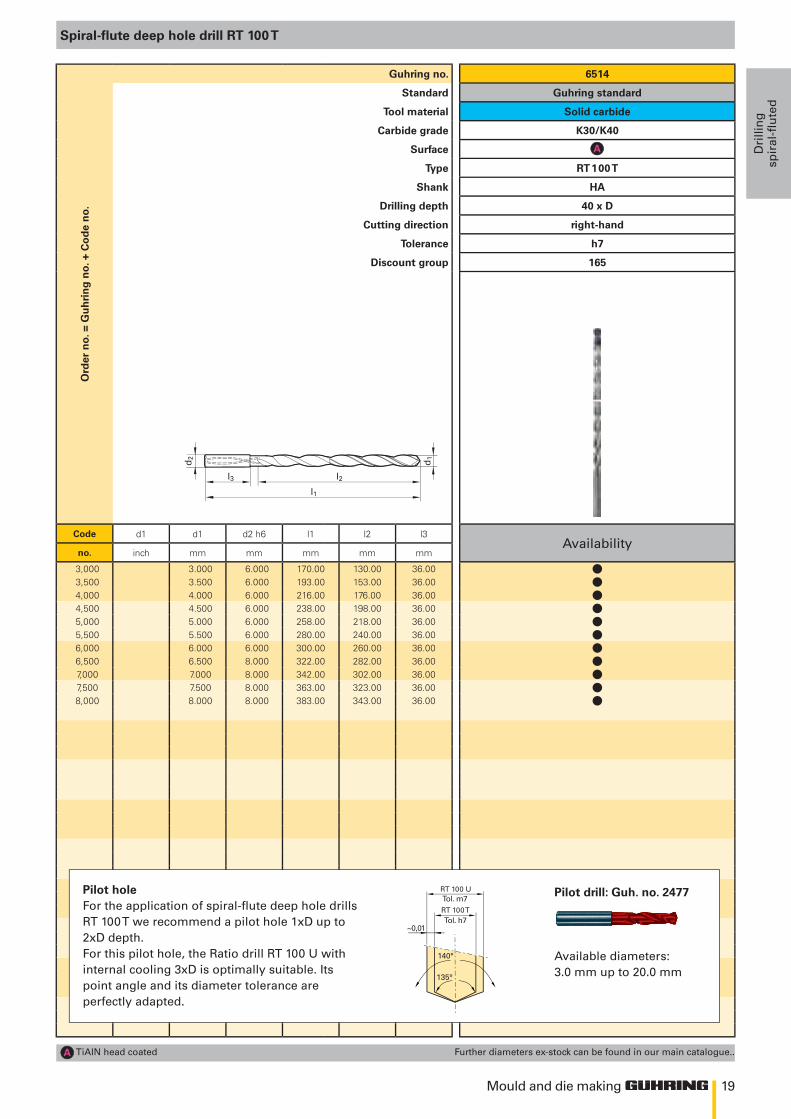
o.Guhring no. 6514
Standard Guhring standard
Tool material Solid carbide
Carbide grade K30/K40
Surface
Type RT 100 T
Shank HA
Drilling depth 40 x D
Cutting direction right-hand
Tolerance h7
Discount group 165
Code d1 d1 d2 h6 l1 l2 l3Availability
no. inch mm mm mm mm mm
3,000 3.000 6.000 170.00 130.00 36.003,500 3.500 6.000 193.00 153.00 36.004,000 4.000 6.000 216.00 176.00 36.004,500 4.500 6.000 238.00 198.00 36.005,000 5.000 6.000 258.00 218.00 36.005,500 5.500 6.000 280.00 240.00 36.006,000 6.000 6.000 300.00 260.00 36.006,500 6.500 8.000 322.00 282.00 36.007,000 7.000 8.000 342.00 302.00 36.007,500 7.500 8.000 363.00 323.00 36.008,000 8.000 8.000 383.00 343.00 36.00
TiAlN head coated Further diameters ex-stock can be found in our main catalogue..
Pilot drill: Guh. no. 2477
Available diameters:3.0 mm up to 20.0 mm
Pilot holeFor the application of spiral-flute deep hole drills RT 100 T we recommend a pilot hole 1xD up to 2xD depth. For this pilot hole, the Ratio drill RT 100 U with internal cooling 3xD is optimally suitable. Its point angle and its diameter tolerance are perfectly adapted.
lllllllllll
20
l1
d1 d2
l2 l3
tmax
tmax = l2-1,5 x d1
l1
d1 d2
l2 l3
tmax
tmax = l2-1,5 x d1
Mould and die making
Drillin
gsp
iral-fluted
Ord
er n
o. =
Gu
hri
ng
no.
+ C
od
e n
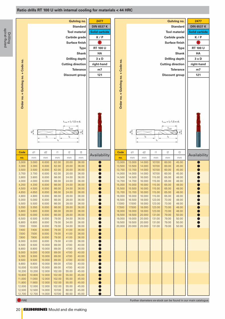
o.Guhring no. 2477
Standard DIN 6537 K
Tool material Solid carbide
Carbide grade K / P
Surface finish
Type RT 100 U
Shank HA
Drilling depth 3 x D
Cutting direction right-hand
Tolerance m7
Discount group 121
Code d1 d2 l1 l2 l3Availability
no. mm mm mm mm mm
3,000 3.000 6.000 62.00 20.00 36.003,300 3.300 6.000 62.00 20.00 36.003,500 3.500 6.000 62.00 20.00 36.003,700 3.700 6.000 62.00 20.00 36.003,800 3.800 6.000 66.00 24.00 36.004,000 4.000 6.000 66.00 24.00 36.004,200 4.200 6.000 66.00 24.00 36.004,500 4.500 6.000 66.00 24.00 36.004,650 4.650 6.000 66.00 24.00 36.004,800 4.800 6.000 66.00 28.00 36.005,000 5.000 6.000 66.00 28.00 36.005,500 5.500 6.000 66.00 28.00 36.005,550 5.550 6.000 66.00 28.00 36.005,800 5.800 6.000 66.00 28.00 36.006,000 6.000 6.000 66.00 28.00 36.006,500 6.500 8.000 79.00 34.00 36.006,800 6.800 8.000 79.00 34.00 36.007,000 7.000 8.000 79.00 34.00 36.007,400 7.400 8.000 79.00 41.00 36.007,500 7.500 8.000 79.00 41.00 36.007,800 7.800 8.000 79.00 41.00 36.008,000 8.000 8.000 79.00 41.00 36.008,500 8.500 10.000 89.00 47.00 40.008,800 8.800 10.000 89.00 47.00 40.009,000 9.000 10.000 89.00 47.00 40.009,300 9.300 10.000 89.00 47.00 40.009,500 9.500 10.000 89.00 47.00 40.009,800 9.800 10.000 89.00 47.00 40.0010,000 10.000 10.000 89.00 47.00 40.0010,200 10.200 12.000 102.00 55.00 45.0010,800 10.800 12.000 102.00 55.00 45.0011,000 11.000 12.000 102.00 55.00 45.0011,800 11.800 12.000 102.00 55.00 45.0012,000 12.000 12.000 102.00 55.00 45.0012,500 12.500 14.000 107.00 60.00 45.0012,700 12.700 14.000 107.00 60.00 45.00
FIRE
Ord
er n
o. =
Gu
hri
ng
no.
+ C
od
e n
o.
Guhring no. 2477
Standard DIN 6537 K
Tool material Solid carbide
Carbide grade K / P
Surface finish
Type RT 100 U
Shank HA
Drilling depth 3 x D
Cutting direction right-hand
Tolerance m7
Discount group 121
Code d1 d2 l1 l2 l3Availability
no. mm mm mm mm mm
13,000 13.000 14.000 107.00 60.00 45.0013,500 13.500 14.000 107.00 60.00 45.0013,700 13.700 14.000 107.00 60.00 45.0014,000 14.000 14.000 107.00 60.00 45.0014,500 14.500 16.000 115.00 65.00 48.0014,700 14.700 16.000 115.00 65.00 48.0015,000 15.000 16.000 115.00 65.00 48.0015,500 15.500 16.000 115.00 65.00 48.0015,700 15.700 16.000 115.00 65.00 48.0016,000 16.000 16.000 115.00 65.00 48.0016,500 16.500 18.000 123.00 73.00 48.0017,000 17.000 18.000 123.00 73.00 48.0017,500 17.500 18.000 123.00 73.00 48.0018,000 18.000 18.000 123.00 73.00 48.0018,500 18.500 20.000 131.00 79.00 50.0019,000 19.000 20.000 131.00 79.00 50.0019,500 19.500 20.000 131.00 79.00 50.0020,000 20.000 20.000 131.00 79.00 50.00
Further diameters ex-stock can be found in our main catalogue.
Ratio drills RT 100 U with internal cooling for materials < 44 HRC
llllllllllllllllllllllllllllllllllll
llllllllllllllllll
21
l1
d1 d2
l2 l3
Mould and die making
Dri
llin
gsp
iral
-flu
ted
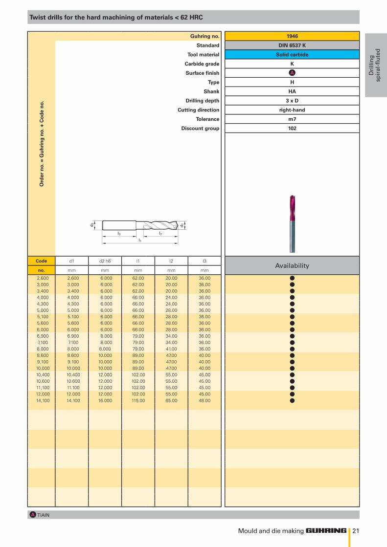
Twist drills for the hard machining of materials < 62 HRC
Ord
er n
o. =
Gu
hri
ng
no.
+ C
od
e n
o.Guhring no. 1946
Standard DIN 6537 K
Tool material Solid carbide
Carbide grade K
Surface finish
Type H
Shank HA
Drilling depth 3 x D
Cutting direction right-hand
Tolerance m7
Discount group 102
Code d1 d2 h6 l1 l2 l3Availability
no. mm mm mm mm mm
2,600 2.600 6.000 62.00 20.00 36.003,000 3.000 6.000 62.00 20.00 36.003,400 3.400 6.000 62.00 20.00 36.004,000 4.000 6.000 66.00 24.00 36.004,300 4.300 6.000 66.00 24.00 36.005,000 5.000 6.000 66.00 28.00 36.005,100 5.100 6.000 66.00 28.00 36.005,600 5.600 6.000 66.00 28.00 36.006,000 6.000 6.000 66.00 28.00 36.006,900 6.900 8.000 79.00 34.00 36.007,100 7.100 8.000 79.00 34.00 36.008,000 8.000 8.000 79.00 41.00 36.008,600 8.600 10.000 89.00 47.00 40.009,100 9.100 10.000 89.00 47.00 40.00
10,000 10.000 10.000 89.00 47.00 40.0010,400 10.400 12.000 102.00 55.00 45.0010,600 10.600 12.000 102.00 55.00 45.0011,100 11.100 12.000 102.00 55.00 45.0012,000 12.000 12.000 102.00 55.00 45.0014,100 14.100 16.000 115.00 65.00 48.00
TiAlN
llllllllllllllllllll
22 Mould and die making
Drillin
gsp
iral-fluted
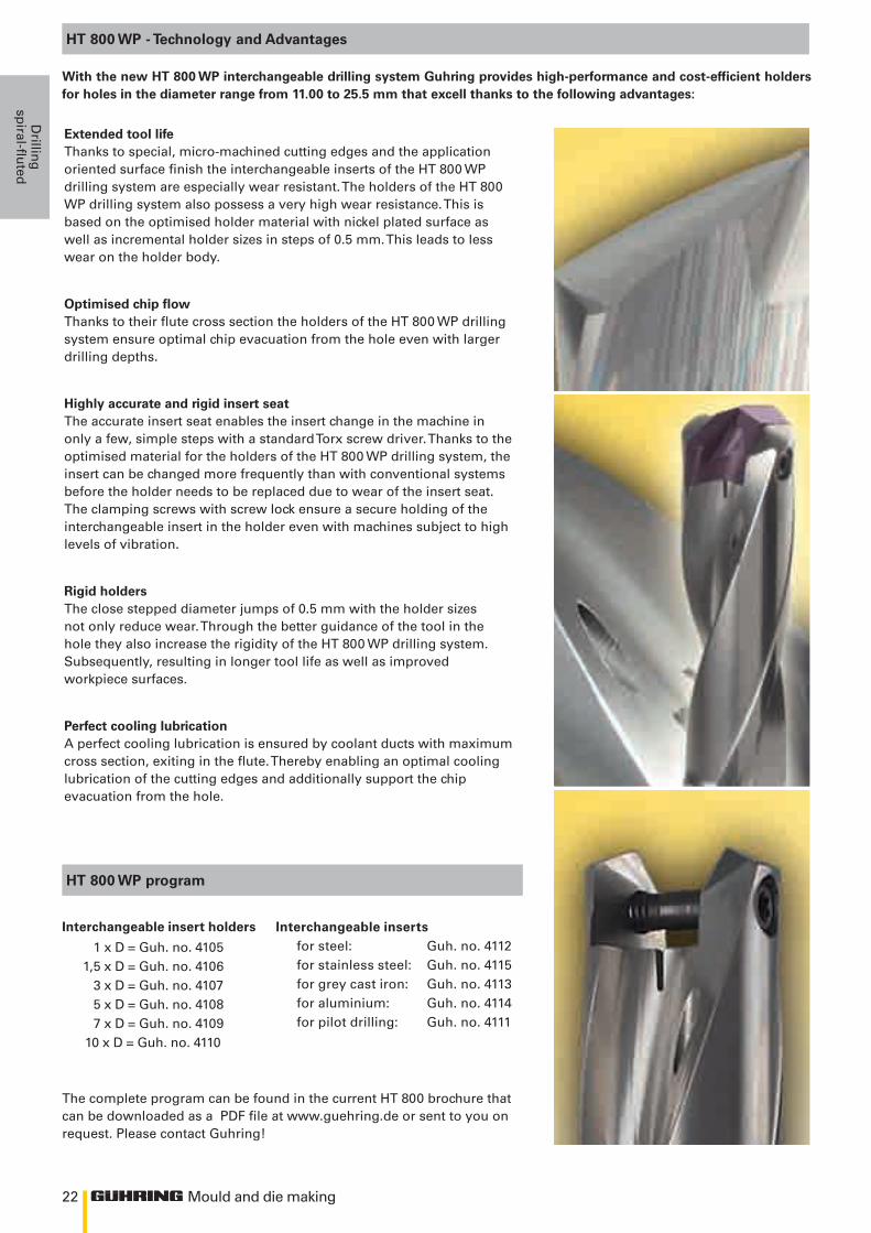
HT 800 WP - Technology and Advantages
Extended tool lifeThanks to special, micro-machined cutting edges and the application oriented surface finish the interchangeable inserts of the HT 800 WP drilling system are especially wear resistant. The holders of the HT 800 WP drilling system also possess a very high wear resistance. This is based on the optimised holder material with nickel plated surface as well as incremental holder sizes in steps of 0.5 mm. This leads to less wear on the holder body.
Optimised chip flowThanks to their flute cross section the holders of the HT 800 WP drilling system ensure optimal chip evacuation from the hole even with larger drilling depths.
Highly accurate and rigid insert seatThe accurate insert seat enables the insert change in the machine in only a few, simple steps with a standard Torx screw driver. Thanks to the optimised material for the holders of the HT 800 WP drilling system, the insert can be changed more frequently than with conventional systems before the holder needs to be replaced due to wear of the insert seat.The clamping screws with screw lock ensure a secure holding of the interchangeable insert in the holder even with machines subject to high levels of vibration.
Rigid holdersThe close stepped diameter jumps of 0.5 mm with the holder sizes not only reduce wear. Through the better guidance of the tool in the hole they also increase the rigidity of the HT 800 WP drilling system. Subsequently, resulting in longer tool life as well as improved workpiece surfaces.
Perfect cooling lubrication A perfect cooling lubrication is ensured by coolant ducts with maximum cross section, exiting in the flute. Thereby enabling an optimal cooling lubrication of the cutting edges and additionally support the chip evacuation from the hole.
HT 800 WP program
Interchangeable insert holders
1 x D = Guh. no. 4105 1,5 x D = Guh. no. 4106 3 x D = Guh. no. 4107 5 x D = Guh. no. 4108 7 x D = Guh. no. 4109 10 x D = Guh. no. 4110
Interchangeable inserts for steel: Guh. no. 4112for stainless steel: Guh. no. 4115for grey cast iron: Guh. no. 4113for aluminium: Guh. no. 4114for pilot drilling: Guh. no. 4111
With the new HT 800 WP interchangeable drilling system Guhring provides high-performance and cost-efficient holders for holes in the diameter range from 11.00 to 25.5 mm that excell thanks to the following advantages:
The complete program can be found in the current HT 800 brochure that can be downloaded as a PDF file at www.guehring.de or sent to you on request. Please contact Guhring!
23
h
d1
d3
d2 h
6
Zylinderschaft DIN 6535-HE
l 2 l 3
l 1
l 4
Mould and die making
Dri
llin
gsp
iral
-flu
ted
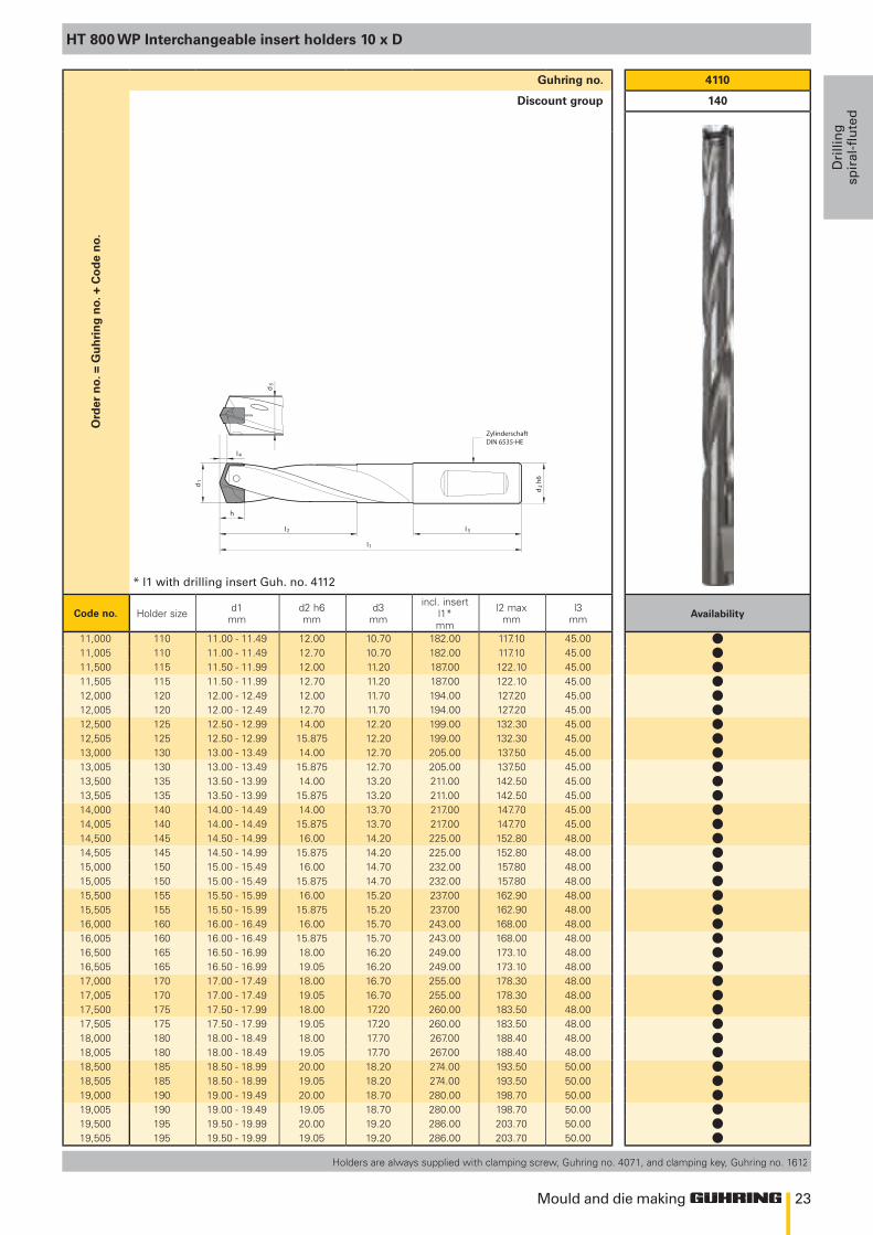
HT 800 WP Interchangeable insert holders 10 x D
Holders are always supplied with clamping screw, Guhring no. 4071, and clamping key, Guhring no. 1612
4110
140
Availability
Ord
er n
o. =
Gu
hri
ng
no.
+ C
od
e n
o.Guhring no.
Discount group
* l1 with drilling insert Guh. no. 4112
Code no. Holder size d1mm
d2 h6mm
d3mm
incl. insertl1*mm
l2 maxmm
l3mm
11,000 110 11.00 - 11.49 12.00 10.70 182.00 117.10 45.0011,005 110 11.00 - 11.49 12.70 10.70 182.00 117.10 45.0011,500 115 11.50 - 11.99 12.00 11.20 187.00 122.10 45.0011,505 115 11.50 - 11.99 12.70 11.20 187.00 122.10 45.0012,000 120 12.00 - 12.49 12.00 11.70 194.00 127.20 45.0012,005 120 12.00 - 12.49 12.70 11.70 194.00 127.20 45.0012,500 125 12.50 - 12.99 14.00 12.20 199.00 132.30 45.0012,505 125 12.50 - 12.99 15.875 12.20 199.00 132.30 45.0013,000 130 13.00 - 13.49 14.00 12.70 205.00 137.50 45.0013,005 130 13.00 - 13.49 15.875 12.70 205.00 137.50 45.0013,500 135 13.50 - 13.99 14.00 13.20 211.00 142.50 45.0013,505 135 13.50 - 13.99 15.875 13.20 211.00 142.50 45.0014,000 140 14.00 - 14.49 14.00 13.70 217.00 147.70 45.0014,005 140 14.00 - 14.49 15.875 13.70 217.00 147.70 45.0014,500 145 14.50 - 14.99 16.00 14.20 225.00 152.80 48.0014,505 145 14.50 - 14.99 15.875 14.20 225.00 152.80 48.0015,000 150 15.00 - 15.49 16.00 14.70 232.00 157.80 48.0015,005 150 15.00 - 15.49 15.875 14.70 232.00 157.80 48.0015,500 155 15.50 - 15.99 16.00 15.20 237.00 162.90 48.0015,505 155 15.50 - 15.99 15.875 15.20 237.00 162.90 48.0016,000 160 16.00 - 16.49 16.00 15.70 243.00 168.00 48.0016,005 160 16.00 - 16.49 15.875 15.70 243.00 168.00 48.0016,500 165 16.50 - 16.99 18.00 16.20 249.00 173.10 48.0016,505 165 16.50 - 16.99 19.05 16.20 249.00 173.10 48.0017,000 170 17.00 - 17.49 18.00 16.70 255.00 178.30 48.0017,005 170 17.00 - 17.49 19.05 16.70 255.00 178.30 48.0017,500 175 17.50 - 17.99 18.00 17.20 260.00 183.50 48.0017,505 175 17.50 - 17.99 19.05 17.20 260.00 183.50 48.0018,000 180 18.00 - 18.49 18.00 17.70 267.00 188.40 48.0018,005 180 18.00 - 18.49 19.05 17.70 267.00 188.40 48.0018,500 185 18.50 - 18.99 20.00 18.20 274.00 193.50 50.0018,505 185 18.50 - 18.99 19.05 18.20 274.00 193.50 50.0019,000 190 19.00 - 19.49 20.00 18.70 280.00 198.70 50.0019,005 190 19.00 - 19.49 19.05 18.70 280.00 198.70 50.0019,500 195 19.50 - 19.99 20.00 19.20 286.00 203.70 50.0019,505 195 19.50 - 19.99 19.05 19.20 286.00 203.70 50.00
llllllllllllllllllllllllllllllllllll
24
h
d1
d3
d2 h
6
Zylinderschaft DIN 6535-HE
l 2 l 3
l 1
l 4
150°
140°
~0,01
#4111Tol. m7
#4112
Mould and die making
Drillin
gsp
iral-fluted
4110
140
Availability
Ord
er n
o. =
Gu
hri
ng
no.
+ C
od
e n
o.Guhring no.
Discount group
* l1 with drilling insert Guh. no. 4112
Code no. Holder size d1mm
d2 h6mm
d3mm
incl. insertl1*mm
l2 maxmm
l3mm
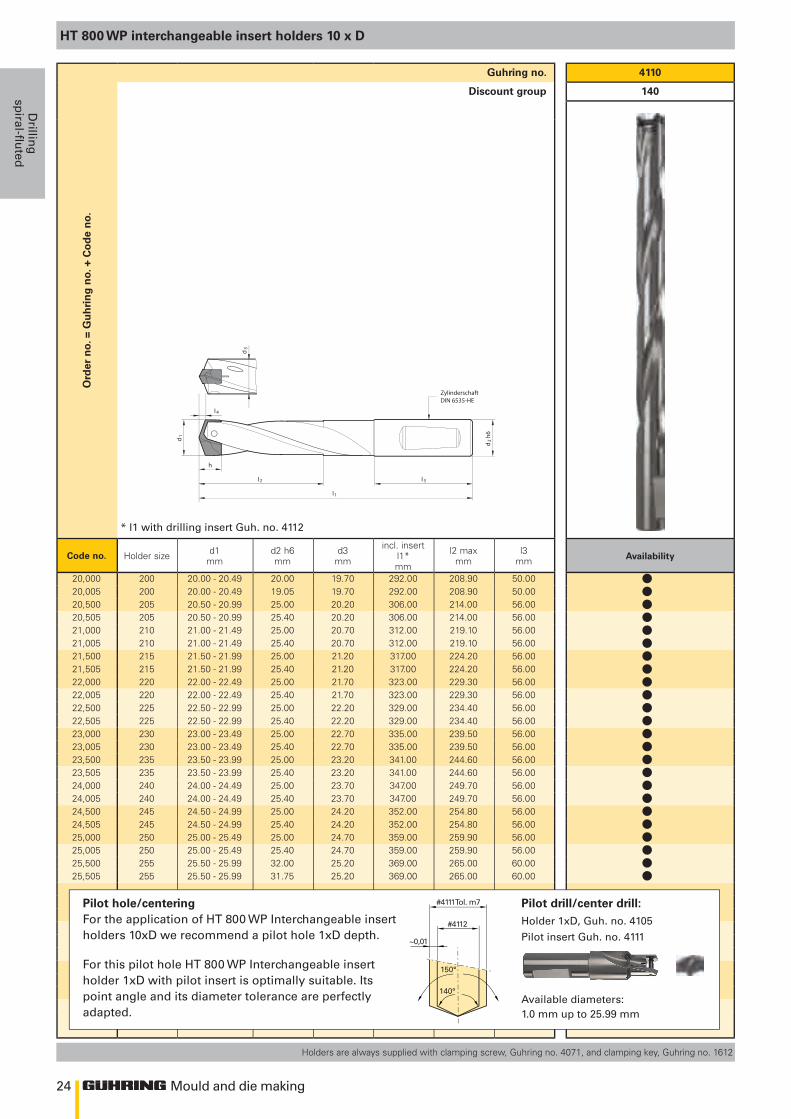
Holders are always supplied with clamping screw, Guhring no. 4071, and clamping key, Guhring no. 1612
HT 800 WP interchangeable insert holders 10 x D
20,000 200 20.00 - 20.49 20.00 19.70 292.00 208.90 50.0020,005 200 20.00 - 20.49 19.05 19.70 292.00 208.90 50.0020,500 205 20.50 - 20.99 25.00 20.20 306.00 214.00 56.0020,505 205 20.50 - 20.99 25.40 20.20 306.00 214.00 56.0021,000 210 21.00 - 21.49 25.00 20.70 312.00 219.10 56.0021,005 210 21.00 - 21.49 25.40 20.70 312.00 219.10 56.0021,500 215 21.50 - 21.99 25.00 21.20 317.00 224.20 56.0021,505 215 21.50 - 21.99 25.40 21.20 317.00 224.20 56.0022,000 220 22.00 - 22.49 25.00 21.70 323.00 229.30 56.0022,005 220 22.00 - 22.49 25.40 21.70 323.00 229.30 56.0022,500 225 22.50 - 22.99 25.00 22.20 329.00 234.40 56.0022,505 225 22.50 - 22.99 25.40 22.20 329.00 234.40 56.0023,000 230 23.00 - 23.49 25.00 22.70 335.00 239.50 56.0023,005 230 23.00 - 23.49 25.40 22.70 335.00 239.50 56.0023,500 235 23.50 - 23.99 25.00 23.20 341.00 244.60 56.0023,505 235 23.50 - 23.99 25.40 23.20 341.00 244.60 56.0024,000 240 24.00 - 24.49 25.00 23.70 347.00 249.70 56.0024,005 240 24.00 - 24.49 25.40 23.70 347.00 249.70 56.0024,500 245 24.50 - 24.99 25.00 24.20 352.00 254.80 56.0024,505 245 24.50 - 24.99 25.40 24.20 352.00 254.80 56.0025,000 250 25.00 - 25.49 25.00 24.70 359.00 259.90 56.0025,005 250 25.00 - 25.49 25.40 24.70 359.00 259.90 56.0025,500 255 25.50 - 25.99 32.00 25.20 369.00 265.00 60.0025,505 255 25.50 - 25.99 31.75 25.20 369.00 265.00 60.00
Pilot hole/centeringFor the application of HT 800 WP Interchangeable insert holders 10xD we recommend a pilot hole 1xD depth.
For this pilot hole HT 800 WP Interchangeable insert holder 1xD with pilot insert is optimally suitable. Its point angle and its diameter tolerance are perfectly adapted.
Pilot drill/center drill: Holder 1xD, Guh. no. 4105
Pilot insert Guh. no. 4111
Available diameters: 1.0 mm up to 25.99 mm
llllllllllllllllllllllll
25
l 4
h
d1
b
l4
h
d1
b
Mould and die making
Dri
llin
gsp
iral
-flu
ted
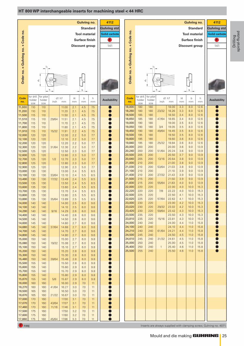
HT 800 WP interchangeable inserts for machining steel < 44 HRC
4112
Guhring std.
Solid carbide
141
Availability
4112
Guhring std.
Solid carbide
141
Availability
11,000 110 110 11.00 2.1 4.5 7.511,200 110 110 11.20 2.1 4.5 7.511,500 115 110 11.50 2.1 4.5 7.511,510 115 110 29/64 11.51 2.1 4.5 7.511,700 115 110 11.70 2.1 4.5 7.511,800 115 110 11.80 2.1 4.5 7.511,910 115 110 15/32 11.91 2.2 4.5 7.512,000 120 120 12.00 2.2 5.0 7.712,100 120 120 12.10 2.2 5.0 7.712,200 120 120 12.20 2.2 5.0 7.712,300 120 120 31/64 12.30 2.2 5.0 7.712,500 125 120 12.50 2.3 5.0 7.712,600 125 120 12.60 2.3 5.0 7.712,700 125 120 1/2 12.70 2.3 5.0 7.712,800 125 120 12.80 2.3 5.0 7.712,900 125 120 12.90 2.3 5.0 7.713,000 130 130 13.00 2.4 5.5 8.513,100 130 130 33/64 13.10 2.4 5.5 8.513,490 130 130 17/32 13.49 2.4 5.5 8.513,500 135 130 13.50 2.4 5.5 8.513,600 135 130 13.60 2.4 5.5 8.513,700 135 130 13.70 2.4 5.5 8.513,800 135 130 13.80 2.5 5.5 8.513,890 135 130 35/64 13.89 2.5 5.5 8.514,000 140 140 14.00 2.5 6.0 9.614,100 140 140 14.10 2.5 6.0 9.614,290 140 140 9/16 14.29 2.6 6.0 9.614,400 140 140 14.40 2.6 6.0 9.614,500 145 140 14.50 2.6 6.0 9.614,600 145 140 14.60 2.7 6.0 9.614,680 145 140 37/64 14.68 2.7 6.0 9.614,700 145 140 14.70 2.7 6.0 9.614,800 145 140 14.80 2.7 6.0 9.615,000 150 140 15.00 2.7 6.0 9.815,080 150 140 19/32 15.08 2.7 6.0 9.815,100 150 140 15.10 2.7 6.0 9.815,200 150 140 15.20 2.8 6.0 9.815,300 150 140 15.30 2.8 6.0 9.815,480 150 140 39/64 15.48 2.8 6.0 9.815,500 155 140 15.50 2.8 6.0 9.815,600 155 140 15.60 2.9 6.0 9.815,700 155 140 15.70 2.9 6.0 9.815,800 155 140 15.80 2.9 6.0 9.815,870 155 140 5/8 15.87 2.9 6.0 9.816,000 160 160 16.00 2.9 7.0 1116,270 160 160 41/64 16.27 3.0 7.0 1116,500 165 160 16.50 3.0 7.0 1116,670 165 160 21/32 16.67 3.0 7.0 1117,000 170 160 17.00 3.1 7.0 1117,070 170 160 43/64 17.07 3.1 7.0 1117,460 170 160 11/16 17.46 3.1 7.0 1117,500 175 160 17.50 3.2 7.0 1117,600 175 160 17.60 3.2 7.0 1117,860 175 160 45/64 17.86 3.3 7.0 11
Ord
er n
o. =
Gu
hri
ng
no.
+ C
od
e n
o.Guhring no.
Standard
Tool material
Surface finish
Discount group
Code no.
for drill.holdersize
for pilotholdersize
d1 h7inch mm
l4mm
bmm
hmm
Ord
er n
o. =
Gu
hri
ng
no.
+ C
od
e n
o.
Guhring no.
Standard
Tool material
Surface finish
Discount group
Code no.
for drill.holdersize
for pilotholdersize
d1 h7inch mm
l4mm
bmm
hmm
18,000 180 180 18.00 3.3 8.0 12.618,260 180 180 23/32 18.26 3.3 8.0 12.618,500 185 180 18.50 3.4 8.0 12.618,650 185 180 47/64 18.65 3.4 8.0 12.619,000 190 180 19.00 3.5 8.0 12.619,050 190 180 3/4 19.05 3.5 8.0 12.619,450 190 180 49/64 19.45 3.5 8.0 12.619,500 195 180 19.50 3.5 8.0 12.619,600 195 180 19.60 3.6 8.0 12.619,840 195 180 25/32 19.84 3.6 8.0 12.620,000 200 200 20.00 3.6 9.0 13.920,240 200 200 51/64 20.24 3.6 9.0 13.920,500 205 200 20.50 3.7 9.0 13.920,640 205 200 13/16 20.64 3.8 9.0 13.921,000 210 200 21.00 3.8 9.0 13.921,030 210 200 53/64 21.03 3.8 9.0 13.921,100 210 200 21.10 3.9 9.0 13.921,430 210 200 27/32 21.43 3.9 9.0 13.921,500 215 200 21.50 3.9 9.0 13.921,830 215 200 55/64 21.83 4.0 9.0 13.922,000 220 220 22.00 4.0 10.0 15.322,220 220 220 7/8 22.22 4.0 10.0 15.322,500 225 220 22.50 4.1 10.0 15.322,620 225 220 57/64 22.62 4.1 10.0 15.323,000 230 220 23.00 4.2 10.0 15.323,020 230 220 29/32 23.02 4.2 10.0 15.323,420 230 220 59/64 23.42 4.3 10.0 15.323,500 235 220 23.50 4.3 10.0 15.323,810 235 220 15/16 23.81 4.3 10.0 15.324,000 240 240 24.00 4.4 11.0 15.824,100 240 240 24.10 4.4 11.0 15.824,210 240 240 61/64 24.21 4.4 11.0 15.824,500 245 240 24.50 4.5 11.0 15.824,610 245 240 31/32 24.61 4.5 11.0 15.825,000 250 240 25.00 4.5 11.0 15.825,400 250 240 1 25.40 4.6 11.0 15.825,500 255 240 25.50 4.6 11.0 15.8
Inserts are always supplied with clamping screw, Guhring no. 4071.FIRE
llllllllllllllllllllllllllllllllllllllllllllllllllllll
lllllllllllllllllllllllllllllllllllll
26 Mould and die making
Drillin
gsp
iral-fluted
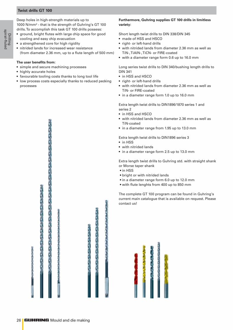
Twist drills GT 100
Deep holes in high-strength materials up to 1000 N/mm² - that is the strength of Guhring‘s GT 100 drills. To accomplish this task GT 100 drills possess:• ground, bright flutes with large chip space for good
cooling and easy chip evacuation• a strengthened core for high rigidity• nitrided lands for increased wear resistance
(from diameter 2.36 mm, up to a flute length of 500 mm)
The user benefits from: • simple and secure machining processes• highly accurate holes• favourable tooling costs thanks to long tool life• low process costs especially thanks to reduced pecking
processes
Furthermore, Guhring supplies GT 100 drills in limitless variety:
Short length twist drills to DIN 338/DIN 345• made of HSS and HSCO• right- or left-hand drills• with nitrided lands from diameter 2.36 mm as well as
TiN-, TiAlN-, TiCN- or FIRE-coated• with a diameter range form 0.6 up to 16.0 mm
Long series twist drills to DIN 340/bushing length drills to DIN 341• in HSS and HSCO• right- or left-hand drills• with nitrided lands from diameter 2.36 mm as well as
TiN- or FIRE-coated• in a diameter range form 1.0 up to 16.0 mm
Extra length twist drills to DIN1896/1870 series 1 and series 2• in HSS and HSCO• with nitrided lands from diameter 2.36 mm as well as
TiN-coated• in a diameter range from 1.95 up to 13.0 mm
Extra length twist drills to DIN1896 series 3• in HSS • with nitrided lands• in a diameter range form 2.5 up to 13.0 mm
Extra length twist drills to Guhring std. with straight shank or Morse taper shank• in HSS • bright or with nitrided lands• in a diameter range form 6.0 up to 12.0 mm• with flute lenghts from 400 up to 850 mm
The complete GT 100 program can be found in Guhring‘s current main catalogue that is available on request. Please contact us!
27
>Ø2,36
>Ø2,36
l1
d1
l2
l1
d1
l2
Mould and die making
Dri
llin
gsp
iral
-flu
ted
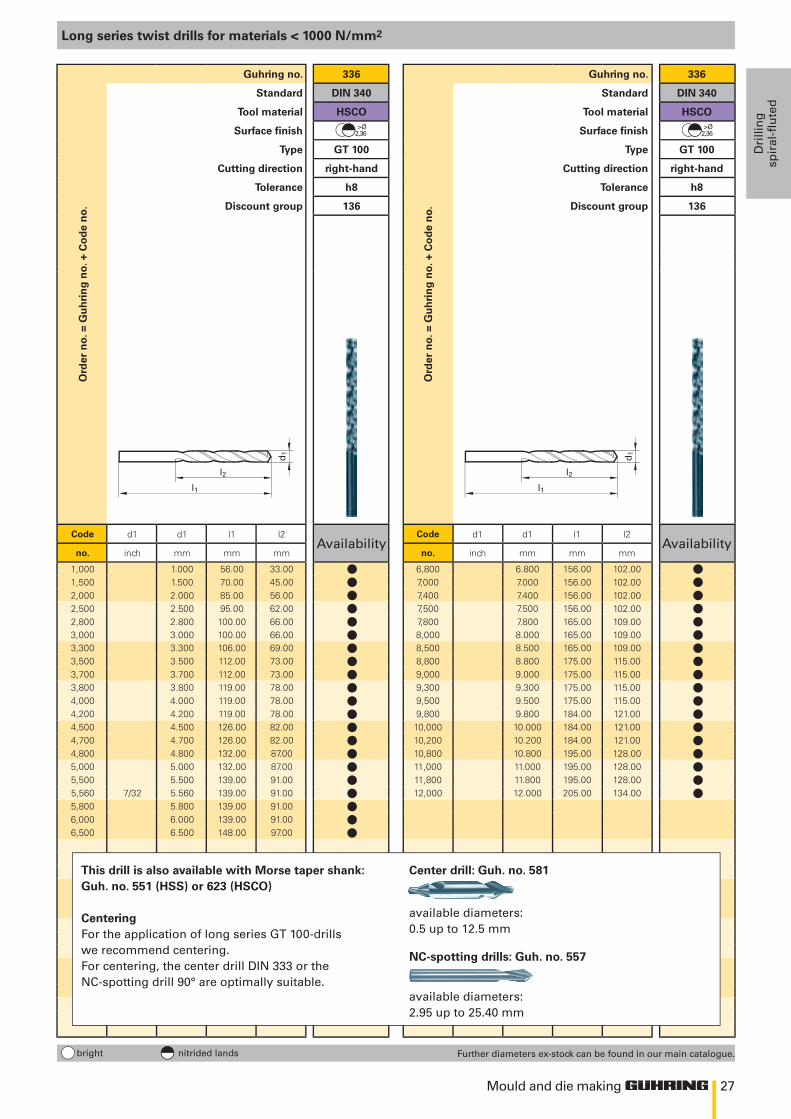
Long series twist drills for materials < 1000 N/mm2
Ord
er n
o. =
Gu
hri
ng
no.
+ C
od
e n
o.Guhring no. 336
Standard DIN 340
Tool material HSCO
Surface finish
Type GT 100
Cutting direction right-hand
Tolerance h8
Discount group 136
Code d1 d1 l1 l2Availability
no. inch mm mm mm
1,000 1.000 56.00 33.001,500 1.500 70.00 45.002,000 2.000 85.00 56.002,500 2.500 95.00 62.002,800 2.800 100.00 66.003,000 3.000 100.00 66.003,300 3.300 106.00 69.003,500 3.500 112.00 73.003,700 3.700 112.00 73.003,800 3.800 119.00 78.004,000 4.000 119.00 78.004,200 4.200 119.00 78.004,500 4.500 126.00 82.004,700 4.700 126.00 82.004,800 4.800 132.00 87.005,000 5.000 132.00 87.005,500 5.500 139.00 91.005,560 7/32 5.560 139.00 91.005,800 5.800 139.00 91.006,000 6.000 139.00 91.006,500 6.500 148.00 97.00
bright nitrided lands
Ord
er n
o. =
Gu
hri
ng
no.
+ C
od
e n
o.
Guhring no. 336
Standard DIN 340
Tool material HSCO
Surface finish
Type GT 100
Cutting direction right-hand
Tolerance h8
Discount group 136
Code d1 d1 l1 l2Availability
no. inch mm mm mm
6,800 6.800 156.00 102.007,000 7.000 156.00 102.007,400 7.400 156.00 102.007,500 7.500 156.00 102.007,800 7.800 165.00 109.008,000 8.000 165.00 109.008,500 8.500 165.00 109.008,800 8.800 175.00 115.009,000 9.000 175.00 115.009,300 9.300 175.00 115.009,500 9.500 175.00 115.009,800 9.800 184.00 121.0010,000 10.000 184.00 121.0010,200 10.200 184.00 121.0010,800 10.800 195.00 128.0011,000 11.000 195.00 128.0011,800 11.800 195.00 128.0012,000 12.000 205.00 134.00
This drill is also available with Morse taper shank: Guh. no. 551 (HSS) or 623 (HSCO)
CenteringFor the application of long series GT 100-drills we recommend centering. For centering, the center drill DIN 333 or the NC-spotting drill 90° are optimally suitable.
Center drill: Guh. no. 581
available diameters: 0.5 up to 12.5 mm
NC-spotting drills: Guh. no. 557
available diameters: 2.95 up to 25.40 mm
Further diameters ex-stock can be found in our main catalogue.
lllllllllllllllllllll
llllllllllllllllll
28
l1
d1
l2
l1
d1
l2
Mould and die making
Drillin
gsp
iral-fluted
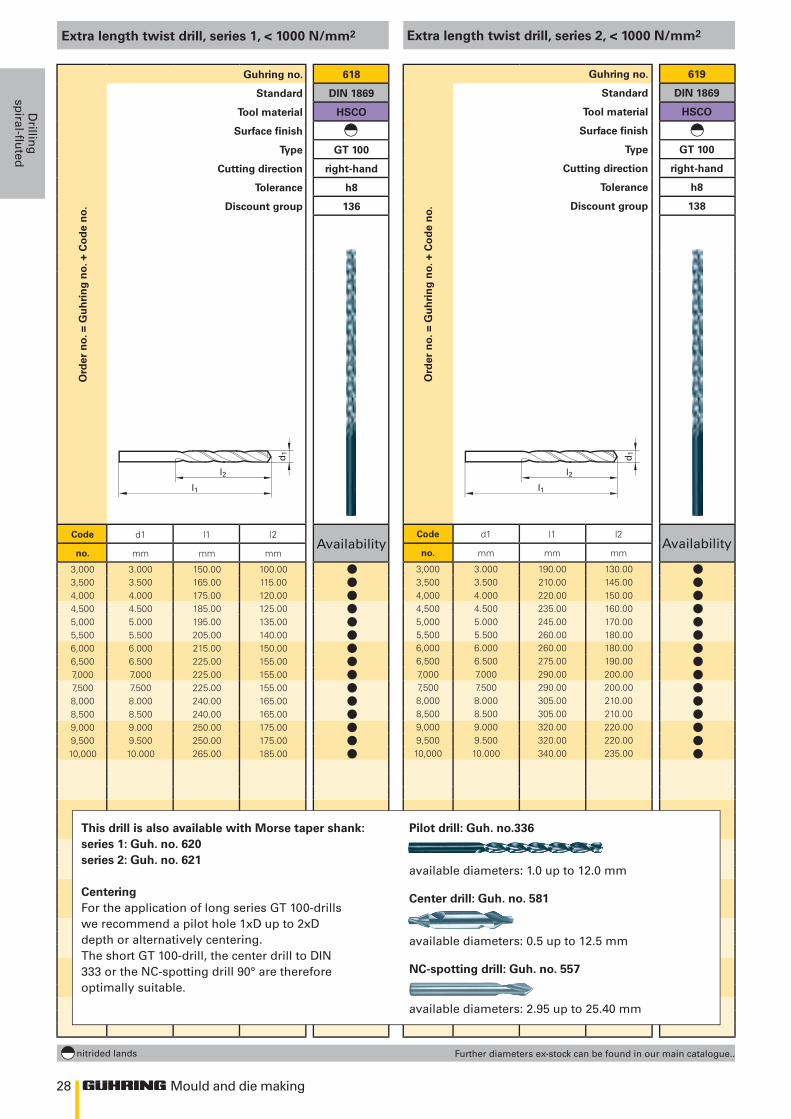
Extra length twist drill, series 1, < 1000 N/mm2
Ord
er n
o. =
Gu
hri
ng
no.
+ C
od
e n
o.Guhring no. 618
Standard DIN 1869
Tool material HSCO
Surface finish
Type GT 100
Cutting direction right-hand
Tolerance h8
Discount group 136
Code d1 l1 l2Availability
no. mm mm mm
3,000 3.000 150.00 100.003,500 3.500 165.00 115.004,000 4.000 175.00 120.004,500 4.500 185.00 125.005,000 5.000 195.00 135.005,500 5.500 205.00 140.006,000 6.000 215.00 150.006,500 6.500 225.00 155.007,000 7.000 225.00 155.007,500 7.500 225.00 155.008,000 8.000 240.00 165.008,500 8.500 240.00 165.009,000 9.000 250.00 175.009,500 9.500 250.00 175.0010,000 10.000 265.00 185.00
nitrided lands
Extra length twist drill, series 2, < 1000 N/mm2
Ord
er n
o. =
Gu
hri
ng
no.
+ C
od
e n
o.
Guhring no. 619
Standard DIN 1869
Tool material HSCO
Surface finish
Type GT 100
Cutting direction right-hand
Tolerance h8
Discount group 138
Code d1 l1 l2Availability
no. mm mm mm
3,000 3.000 190.00 130.003,500 3.500 210.00 145.004,000 4.000 220.00 150.004,500 4.500 235.00 160.005,000 5.000 245.00 170.005,500 5.500 260.00 180.006,000 6.000 260.00 180.006,500 6.500 275.00 190.007,000 7.000 290.00 200.007,500 7.500 290.00 200.008,000 8.000 305.00 210.008,500 8.500 305.00 210.009,000 9.000 320.00 220.009,500 9.500 320.00 220.0010,000 10.000 340.00 235.00
Further diameters ex-stock can be found in our main catalogue..
This drill is also available with Morse taper shank: series 1: Guh. no. 620series 2: Guh. no. 621
CenteringFor the application of long series GT 100-drills we recommend a pilot hole 1xD up to 2xD depth or alternatively centering. The short GT 100-drill, the center drill to DIN 333 or the NC-spotting drill 90° are therefore optimally suitable.
Pilot drill: Guh. no.336
available diameters: 1.0 up to 12.0 mm
Center drill: Guh. no. 581
available diameters: 0.5 up to 12.5 mm
NC-spotting drill: Guh. no. 557
available diameters: 2.95 up to 25.40 mm
lllllllllllllll
lllllllllllllll
29
l1
d1
l2
l1
d1
l2
Mould and die making
Dri
llin
gsp
iral
-flu
ted
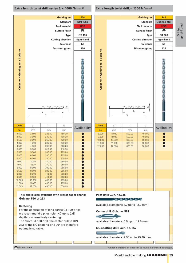
Extra length twist drill, series 3, < 1000 N/mm2
Ord
er n
o. =
Gu
hri
ng
no.
+ C
od
e n
o.Guhring no. 504
Standard DIN 1869
Tool material HSS
Surface finish
Type GT 100
Cutting direction right-hand
Tolerance h8
Discount group 136
Code d1 l1 l2Availability
no. mm mm mm
2,500 2.500 225.00 150.003,000 3.000 240.00 160.003,500 3.500 265.00 180.004,000 4.000 280.00 190.004,500 4.500 295.00 200.005,000 5.000 315.00 210.005,500 5.500 330.00 225.006,000 6.000 330.00 225.006,500 6.500 350.00 235.007,000 7.000 370.00 250.007,500 7.500 370.00 250.008,000 8.000 390.00 265.008,500 8.500 390.00 265.009,000 9.000 410.00 280.009,500 9.500 410.00 280.0010,000 10.000 430.00 295.0011,000 11.000 430.00 295.0012,000 12.000 480.00 330.00
nitrided lands
Extra length twist drill, < 1000 N/mm2
Ord
er n
o. =
Gu
hri
ng
no.
+ C
od
e n
o.
Guhring no. 242
Standard Guhring std.
Tool material HSS
Surface finish
Type GT 100
Cutting direction right-hand
Tolerance h8
Discount group 136
Code d1 l1 l2Availability
no. mm mm mm
6,000 6.000 500.00 400.008,000 8.000 500.00 400.0010,000 10.000 600.00 500.0011,000 11.000 600.00 500.0012,000 12.000 600.00 500.00
Further diameters ex-stock can be found in our main catalogue.
This drill is also available with Morse taper shank: Guh. no. 566 or 293
CenteringFor the application of long series GT 100-drills we recommend a pilot hole 1xD up to 2xD depth or alternatively centering. The short GT 100-drill, the center drill to DIN 333 or the NC-spotting drill 90° are therefore optimally suitable.
Pilot drill: Guh. no.336
available diameters: 1.0 up to 12.0 mm
Center drill: Guh. no. 581
available diameters: 0.5 up to 12.5 mm
NC-spotting drill: Guh. no. 557
available diameters: 2.95 up to 25.40 mm
llllllllllllllllll
lllll
30
l1
d1
l2
l1
d1
l2
Mould and die making
Drillin
gsp
iral-fluted
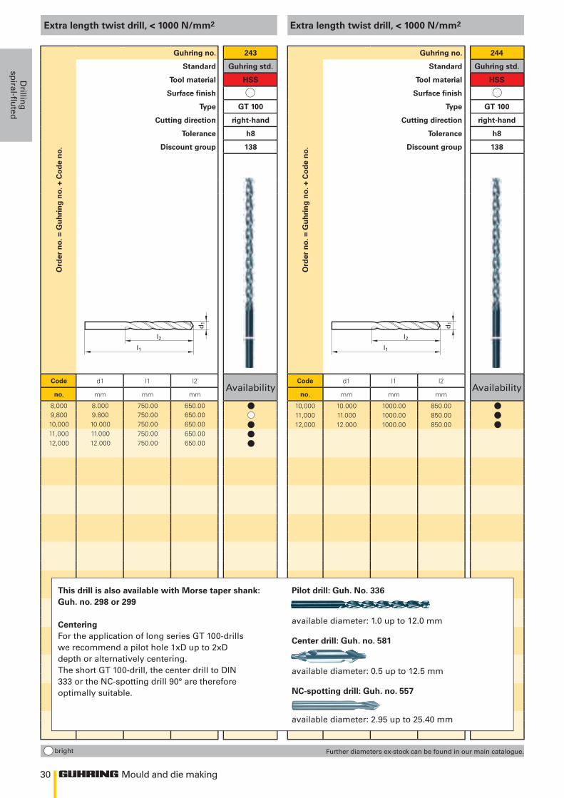
Extra length twist drill, < 1000 N/mm2
Ord
er n
o. =
Gu
hri
ng
no.
+ C
od
e n
o.Guhring no. 243
Standard Guhring std.
Tool material HSS
Surface finish
Type GT 100
Cutting direction right-hand
Tolerance h8
Discount group 138
Code d1 l1 l2Availability
no. mm mm mm
8,000 8.000 750.00 650.009,800 9.800 750.00 650.0010,000 10.000 750.00 650.0011,000 11.000 750.00 650.0012,000 12.000 750.00 650.00
bright
Extra length twist drill, < 1000 N/mm2
Ord
er n
o. =
Gu
hri
ng
no.
+ C
od
e n
o.
Guhring no. 244
Standard Guhring std.
Tool material HSS
Surface finish
Type GT 100
Cutting direction right-hand
Tolerance h8
Discount group 138
Code d1 l1 l2Availability
no. mm mm mm
10,000 10.000 1000.00 850.0011,000 11.000 1000.00 850.0012,000 12.000 1000.00 850.00
Further diameters ex-stock can be found in our main catalogue.
This drill is also available with Morse taper shank: Guh. no. 298 or 299
CenteringFor the application of long series GT 100-drills we recommend a pilot hole 1xD up to 2xD depth or alternatively centering. The short GT 100-drill, the center drill to DIN 333 or the NC-spotting drill 90° are therefore optimally suitable.
Pilot drill: Guh. No. 336
available diameter: 1.0 up to 12.0 mm
Center drill: Guh. no. 581
available diameter: 0.5 up to 12.5 mm
NC-spotting drill: Guh. no. 557
available diameter: 2.95 up to 25.40 mm
l
lll
lll
31
l1
d1
l2
d1
d2
l1
60o
Mould and die making
Dri
llin
gsp
iral
-flu
ted
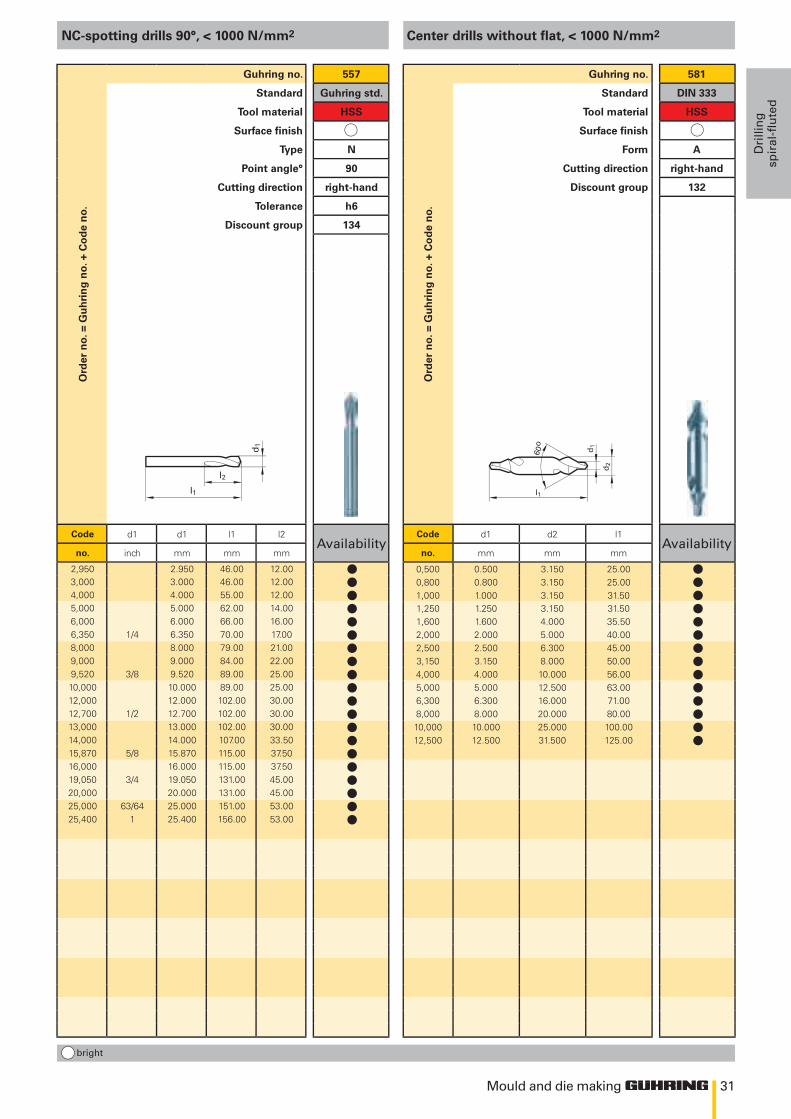
NC-spotting drills 90°, < 1000 N/mm2
Ord
er n
o. =
Gu
hri
ng
no.
+ C
od
e n
o.Guhring no. 557
Standard Guhring std.
Tool material HSS
Surface finish
Type N
Point angle° 90
Cutting direction right-hand
Tolerance h6
Discount group 134
Code d1 d1 l1 l2Availability
no. inch mm mm mm
2,950 2.950 46.00 12.003,000 3.000 46.00 12.004,000 4.000 55.00 12.005,000 5.000 62.00 14.006,000 6.000 66.00 16.006,350 1/4 6.350 70.00 17.008,000 8.000 79.00 21.009,000 9.000 84.00 22.009,520 3/8 9.520 89.00 25.0010,000 10.000 89.00 25.0012,000 12.000 102.00 30.0012,700 1/2 12.700 102.00 30.0013,000 13.000 102.00 30.0014,000 14.000 107.00 33.5015,870 5/8 15.870 115.00 37.5016,000 16.000 115.00 37.5019,050 3/4 19.050 131.00 45.0020,000 20.000 131.00 45.0025,000 63/64 25.000 151.00 53.0025,400 1 25.400 156.00 53.00
bright
Center drills without flat, < 1000 N/mm2
Ord
er n
o. =
Gu
hri
ng
no.
+ C
od
e n
o.
Guhring no. 581
Standard DIN 333
Tool material HSS
Surface finish
Form A
Cutting direction right-hand
Discount group 132
Code d1 d2 l1Availability
no. mm mm mm
0,500 0.500 3.150 25.000,800 0.800 3.150 25.001,000 1.000 3.150 31.501,250 1.250 3.150 31.501,600 1.600 4.000 35.502,000 2.000 5.000 40.002,500 2.500 6.300 45.003,150 3.150 8.000 50.004,000 4.000 10.000 56.005,000 5.000 12.500 63.006,300 6.300 16.000 71.008,000 8.000 20.000 80.0010,000 10.000 25.000 100.0012,500 12.500 31.500 125.00
llllllllllllllllllll
llllllllllllll
die and mould makingdrillinG straight fluted
34
250 500 750 1000
250 500 750 1000
11 10 9 8 7 6 5
Mould and die making
Drillin
g
straigh
t fluted
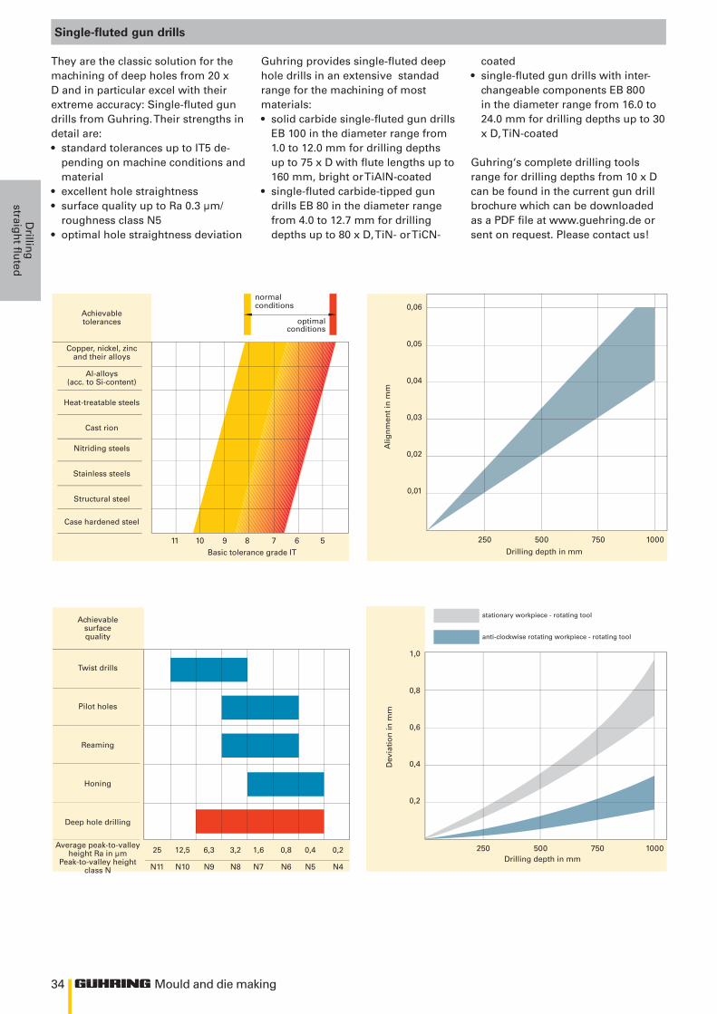
Single-fluted gun drills
They are the classic solution for the machining of deep holes from 20 x D and in particular excel with their extreme accuracy: Single-fluted gun drills from Guhring. Their strengths in detail are:• standard tolerances up to IT5 de-
pending on machine conditions and material
• excellent hole straightness • surface quality up to Ra 0.3 µm/
roughness class N5• optimal hole straightness deviation
Guhring provides single-fluted deep hole drills in an extensive standad range for the machining of most materials: • solid carbide single-fluted gun drills
EB 100 in the diameter range from 1.0 to 12.0 mm for drilling depths up to 75 x D with flute lengths up to 160 mm, bright or TiAlN-coated
• single-fluted carbide-tipped gun drills EB 80 in the diameter range from 4.0 to 12.7 mm for drilling depths up to 80 x D, TiN- or TiCN-
coated• single-fluted gun drills with inter-
changeable components EB 800 in the diameter range from 16.0 to 24.0 mm for drilling depths up to 30 x D, TiN-coated
Guhring‘s complete drilling tools range for drilling depths from 10 x D can be found in the current gun drill brochure which can be downloaded as a PDF file at www.guehring.de or sent on request. Please contact us!
Achievablesurfacequality
Twist drills
Pilot holes
Reaming
Honing
Deep hole drilling
Average peak-to-valley
height Ra in µmPeak-to-valley height
class N
25 12,5 6,3 3,2 1,6 0,8 0,4 0,2 N11 N10 N9 N8 N7 N6 N5 N4
Drilling depth in mm
Dev
iati
on
in m
m
1,0
0,8
0,6
0,4
0,2
stationary workpiece - rotating tool
anti-clockwise rotating workpiece - rotating tool
Achievabletolerances
Copper, nickel, zincand their alloys
Al-alloys(acc. to Si-content)
Heat-treatable steels
Cast rion
Nitriding steels
Stainless steels
Structural steel
Case hardened steel
Basic tolerance grade IT Drilling depth in mm
Alig
nm
ent
in m
m
0,06
0,05
0,04
0,03
0,02
0,01
normalconditions
optimal conditions
35
Mould and die making
Dri
llin
g
stra
igh
t fl
ute
d
Standard Type Tool description Flute length/drilling depth Tool material Surface
finish Diameter range Guhring no.
Discount group
Standard rangepage
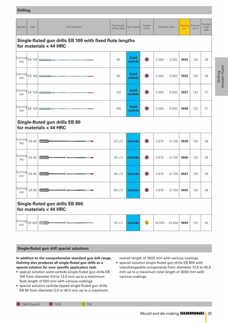
Single-fluted gun drills EB 100 with fixed flute lengths for materials < 44 HRC
Guhring std. EB 100 45
Solid carbide 2.000 - 3.200 5632 123 36
Guhring std. EB 100 80
Solid carbide 2.000 - 5.000 5633 123 36
Guhring std. EB 100 120
Solid carbide 2.000 - 5.000 5637 123 37
Guhring std. EB 100 160
Solid carbide 2.000 - 8.000 5638 123 37
Single-fluted gun drills EB 80 for materials < 44 HRC
Guhring std. EB 80 20 x D Carbide 3.970 - 12.700 5639 123 38
Guhring std. EB 80 30 x D Carbide 3.970 - 12.700 5640 123 38
Guhring std. EB 80 40 x D Carbide 3.970 - 12.700 5641 123 39
Guhring std. EB 80 80 x D Carbide 3.970 - 12.700 5642 123 39
Single-fluted gun drills EB 800 for materials < 44 HRC
Guhring std. EB 800 30 x D Carbide 16.000 - 24.000 5644 123 40
Drilling
TiAlN SuperA TiCN TiN
Single-fluted gun drill special solutions
In addition to the comprehensive standard gun drill range, Guhring also produces all single-fluted gun drills as a special solution for your specific application task. • special solution solid carbide single-fluted gun drills EB
100 from diameter 0.9 to 12.0 mm up to a maximum flute length of 500 mm with various coatings
• special solution carbide-tipped single-fluted gun drills EB 80 from diameter 2.0 to 40.0 mm up to a maximum
overall length of 3000 mm with various coatings• special solution single-fluted gun drills EB 800 with
interchangeable components from diameter 12.0 to 40.0 mm up to a maximum total length of 3000 mm with various coatings
36
l3 l2l1
d2 d
1
l3 l2l1
d2 d
1
Mould and die making
Drillin
g
straigh
t fluted
Ord
er n
o. =
Gu
hri
ng
no.
+ c
od
e n
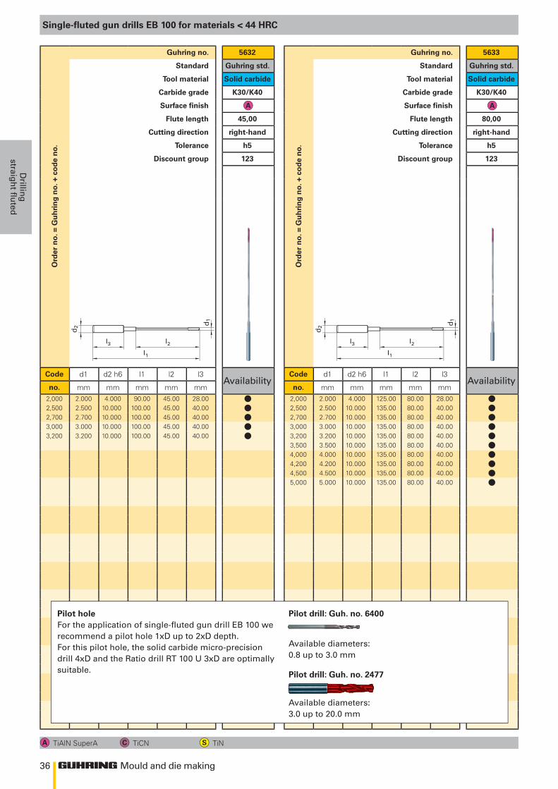
o.Guhring no. 5632
Standard Guhring std.
Tool material Solid carbide
Carbide grade K30/K40
Surface finish
Flute length 45,00
Cutting direction right-hand
Tolerance h5
Discount group 123
Code d1 d2 h6 l1 l2 l3Availability
no. mm mm mm mm mm2,000 2.000 4.000 90.00 45.00 28.002,500 2.500 10.000 100.00 45.00 40.002,700 2.700 10.000 100.00 45.00 40.003,000 3.000 10.000 100.00 45.00 40.003,200 3.200 10.000 100.00 45.00 40.00
Ord
er n
o. =
Gu
hri
ng
no.
+ c
od
e n
o.
Guhring no. 5633
Standard Guhring std.
Tool material Solid carbide
Carbide grade K30/K40
Surface finish
Flute length 80,00
Cutting direction right-hand
Tolerance h5
Discount group 123
Code d1 d2 h6 l1 l2 l3Availability
no. mm mm mm mm mm2,000 2.000 4.000 125.00 80.00 28.002,500 2.500 10.000 135.00 80.00 40.002,700 2.700 10.000 135.00 80.00 40.003,000 3.000 10.000 135.00 80.00 40.003,200 3.200 10.000 135.00 80.00 40.003,500 3.500 10.000 135.00 80.00 40.004,000 4.000 10.000 135.00 80.00 40.004,200 4.200 10.000 135.00 80.00 40.004,500 4.500 10.000 135.00 80.00 40.005,000 5.000 10.000 135.00 80.00 40.00
Single-fluted gun drills EB 100 for materials < 44 HRC
TiAlN SuperA TiCN TiN
Pilot holeFor the application of single-fluted gun drill EB 100 we recommend a pilot hole 1xD up to 2xD depth. For this pilot hole, the solid carbide micro-precision drill 4xD and the Ratio drill RT 100 U 3xD are optimally suitable.
Pilot drill: Guh. no. 6400
Available diameters: 0.8 up to 3.0 mm
Pilot drill: Guh. no. 2477
Available diameters: 3.0 up to 20.0 mm
lllll
llllllllll
37
l3 l2l1
d2 d
1
l3 l2l1
d2 d
1
Mould and die making
Dri
llin
g
stra
igh
t fl
ute
d
Ord
er n
o. =
Gu
hri
ng
no.
+ c
od
e n
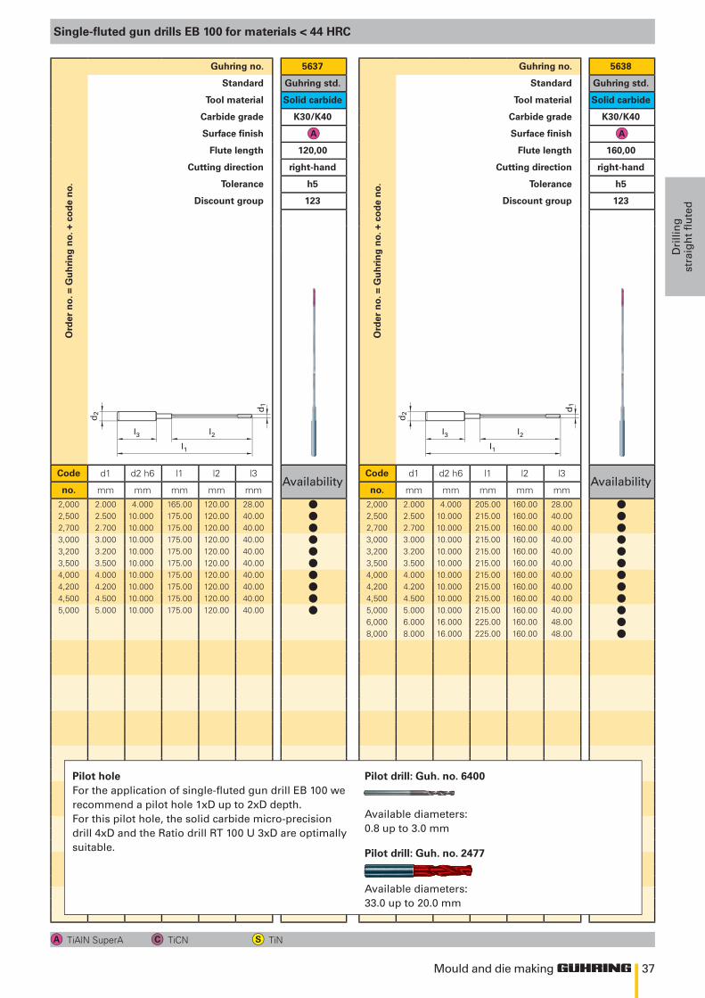
o.Guhring no. 5637
Standard Guhring std.
Tool material Solid carbide
Carbide grade K30/K40
Surface finish
Flute length 120,00
Cutting direction right-hand
Tolerance h5
Discount group 123
Code d1 d2 h6 l1 l2 l3Availability
no. mm mm mm mm mm2,000 2.000 4.000 165.00 120.00 28.002,500 2.500 10.000 175.00 120.00 40.002,700 2.700 10.000 175.00 120.00 40.003,000 3.000 10.000 175.00 120.00 40.003,200 3.200 10.000 175.00 120.00 40.003,500 3.500 10.000 175.00 120.00 40.004,000 4.000 10.000 175.00 120.00 40.004,200 4.200 10.000 175.00 120.00 40.004,500 4.500 10.000 175.00 120.00 40.005,000 5.000 10.000 175.00 120.00 40.00
Ord
er n
o. =
Gu
hri
ng
no.
+ c
od
e n
o.
Guhring no. 5638
Standard Guhring std.
Tool material Solid carbide
Carbide grade K30/K40
Surface finish
Flute length 160,00
Cutting direction right-hand
Tolerance h5
Discount group 123
Code d1 d2 h6 l1 l2 l3Availability
no. mm mm mm mm mm2,000 2.000 4.000 205.00 160.00 28.002,500 2.500 10.000 215.00 160.00 40.002,700 2.700 10.000 215.00 160.00 40.003,000 3.000 10.000 215.00 160.00 40.003,200 3.200 10.000 215.00 160.00 40.003,500 3.500 10.000 215.00 160.00 40.004,000 4.000 10.000 215.00 160.00 40.004,200 4.200 10.000 215.00 160.00 40.004,500 4.500 10.000 215.00 160.00 40.005,000 5.000 10.000 215.00 160.00 40.006,000 6.000 16.000 225.00 160.00 48.008,000 8.000 16.000 225.00 160.00 48.00
Single-fluted gun drills EB 100 for materials < 44 HRC
TiAlN SuperA TiCN TiN
Pilot holeFor the application of single-fluted gun drill EB 100 we recommend a pilot hole 1xD up to 2xD depth. For this pilot hole, the solid carbide micro-precision drill 4xD and the Ratio drill RT 100 U 3xD are optimally suitable.
Pilot drill: Guh. no. 6400
Available diameters: 0.8 up to 3.0 mm
Pilot drill: Guh. no. 2477
Available diameters: 33.0 up to 20.0 mm
llllllllll
llllllllllll
38
l3 l2l1
d2 d
1
l3 l2l1
d2 d
1
Mould and die making
Drillin
g
straigh
t fluted
Ord
er n
o. =
Gu
hri
ng
no.
+ c
od
e n
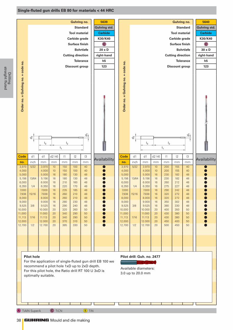
o.Guhring no. 5639
Standard Guhring std.
Tool material Carbide
Carbide grade K30/K40
Surface finish
Bohrtiefe 20 x D
Cutting direction right-hand
Tolerance h5
Discount group 123
Code d1 d1 d2 h6 l1 l2 l3Availability
no. inch mm mm mm mm mm3,970 5/32 3.970 10 150 100 404,000 4.000 10 150 100 405,000 5.000 16 180 130 485,156 13/64 5.156 16 180 130 486,000 6.000 16 210 160 486,350 1/4 6.350 16 220 170 487,000 7.000 16 235 185 487,938 15/16 7.938 16 260 210 488,000 8.000 16 260 210 489,000 9.000 16 280 230 489,525 3/8 9.525 16 290 240 48
10,000 10.000 20 320 260 5011,000 11.000 20 340 290 5011,113 7/16 11.113 20 340 290 5012,000 12.000 20 370 310 5012,700 1/2 12.700 20 385 330 50
Ord
er n
o. =
Gu
hri
ng
no.
+ c
od
e n
o.
Guhring no. 5640
Standard Guhring std.
Tool material Carbide
Carbide grade K30/K40
Surface finish
Bohrtiefe 30 x D
Cutting direction right-hand
Tolerance h5
Discount group 123
Code d1 d1 d2 h6 l1 l2 l3Availability
no. inch mm mm mm mm mm3,970 5/32 3.970 10 200 155 404,000 4.000 10 200 155 405,000 5.000 16 230 182 485,156 13/64 5.156 16 230 182 486,000 6.000 16 260 212 486,350 1/4 6.350 16 275 227 487,000 7.000 16 290 242 487,938 15/16 7.938 16 320 272 488,000 8.000 16 320 272 489,000 9.000 16 350 302 489,525 3/8 9.525 16 380 330 48
10,000 10.000 20 400 350 5011,000 11.000 20 430 380 5011,113 7/16 11.113 20 430 380 5012,000 12.000 20 450 400 5012,700 1/2 12.700 20 500 450 50
Single-fluted gun drills EB 80 for materials < 44 HRC
TiAlN SuperA TiCN TiN
Pilot holeFor the application of single-fluted gun drill EB 100 we recommend a pilot hole 1xD up to 2xD depth. For this pilot hole, the Ratio drill RT 100 U 3xD is optimally suitable.
Pilot drill: Guh. no. 2477
Available diameters: 3.0 up to 20.0 mm
llllllllllllllll
llllllllllllllll
39
l3 l2l1
d2 d
1
l3 l2l1
d2 d
1
Mould and die making
Dri
llin
g
stra
igh
t fl
ute
d
Ord
er n
o. =
Gu
hri
ng
no.
+ c
od
e n
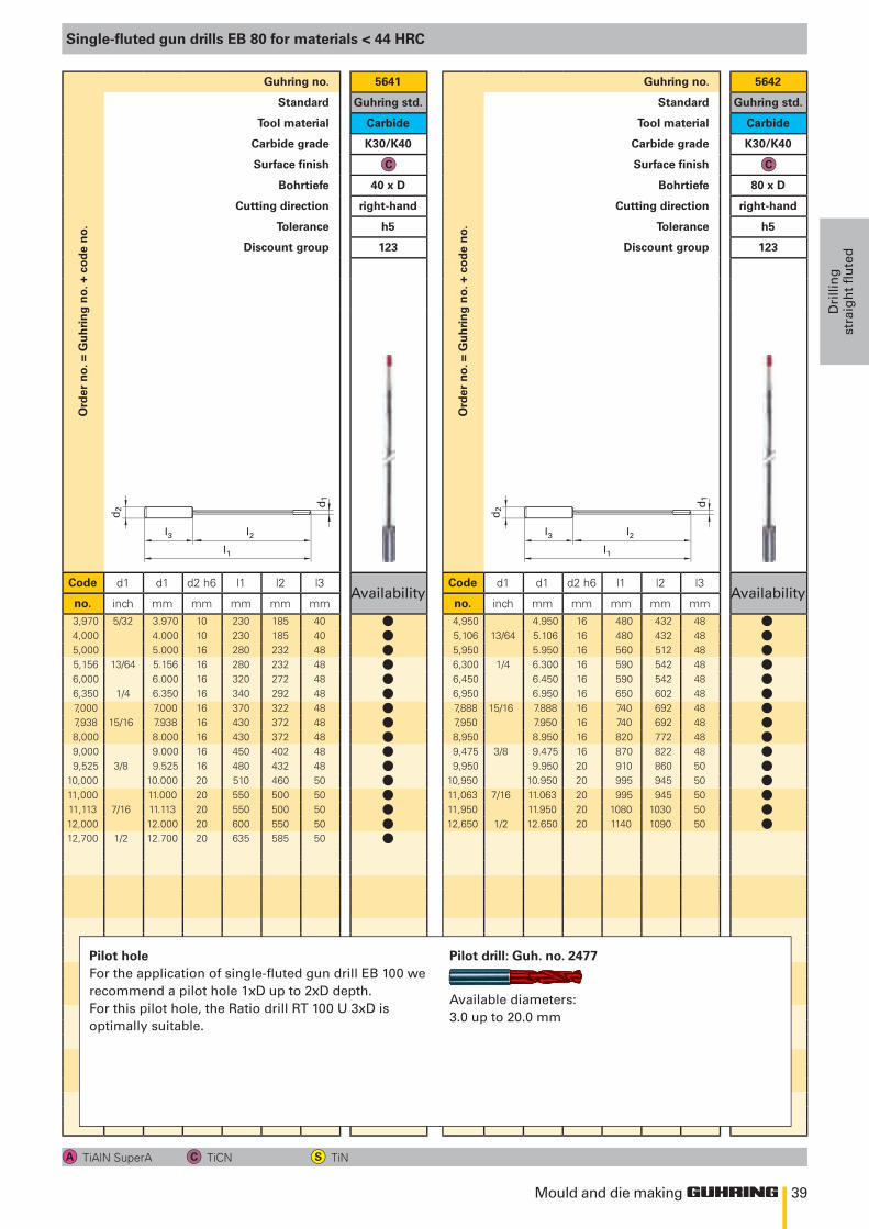
o.Guhring no. 5641
Standard Guhring std.
Tool material Carbide
Carbide grade K30/K40
Surface finish
Bohrtiefe 40 x D
Cutting direction right-hand
Tolerance h5
Discount group 123
Code d1 d1 d2 h6 l1 l2 l3Availability
no. inch mm mm mm mm mm3,970 5/32 3.970 10 230 185 404,000 4.000 10 230 185 405,000 5.000 16 280 232 485,156 13/64 5.156 16 280 232 486,000 6.000 16 320 272 486,350 1/4 6.350 16 340 292 487,000 7.000 16 370 322 487,938 15/16 7.938 16 430 372 488,000 8.000 16 430 372 489,000 9.000 16 450 402 489,525 3/8 9.525 16 480 432 48
10,000 10.000 20 510 460 5011,000 11.000 20 550 500 5011,113 7/16 11.113 20 550 500 5012,000 12.000 20 600 550 5012,700 1/2 12.700 20 635 585 50
Ord
er n
o. =
Gu
hri
ng
no.
+ c
od
e n
o.
Guhring no. 5642
Standard Guhring std.
Tool material Carbide
Carbide grade K30/K40
Surface finish
Bohrtiefe 80 x D
Cutting direction right-hand
Tolerance h5
Discount group 123
Code d1 d1 d2 h6 l1 l2 l3Availability
no. inch mm mm mm mm mm4,950 4.950 16 480 432 485,106 13/64 5.106 16 480 432 485,950 5.950 16 560 512 486,300 1/4 6.300 16 590 542 486,450 6.450 16 590 542 486,950 6.950 16 650 602 487,888 15/16 7.888 16 740 692 487,950 7.950 16 740 692 488,950 8.950 16 820 772 489,475 3/8 9.475 16 870 822 489,950 9.950 20 910 860 50
10,950 10.950 20 995 945 5011,063 7/16 11.063 20 995 945 5011,950 11.950 20 1080 1030 5012,650 1/2 12.650 20 1140 1090 50
Single-fluted gun drills EB 80 for materials < 44 HRC
TiAlN SuperA TiCN TiN
Pilot holeFor the application of single-fluted gun drill EB 100 we recommend a pilot hole 1xD up to 2xD depth. For this pilot hole, the Ratio drill RT 100 U 3xD is optimally suitable.
Pilot drill: Guh. no. 2477
Available diameters: 3.0 up to 20.0 mm
llllllllllllllll
lllllllllllllll
40
l3
d2 d1
l2
l1
Mould and die making
Drillin
g
straigh
t fluted
Ord
er n
o. =
Gu
hri
ng
no.
+ c
od
e n
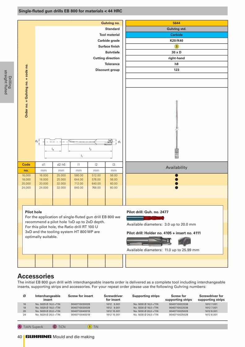
o.Guhring no. 5644
Standard Guhring std.
Tool material Carbide
Carbide grade K20/K40
Surface finish
Bohrtiefe 30 x D
Cutting direction right-hand
Tolerance h8
Discount group 123
Code d1 d2 h6 l1 l2 l3Availability
no. mm mm mm mm mm16,000 16.000 25.000 580.00 512.00 56.0018,000 18.000 25.000 644.00 576.00 56.0020,000 20.000 32.000 712.00 640.00 60.0024,000 24.000 32.000 840.00 768.00 60.00
Single-fluted gun drills EB 800 for materials < 44 HRC
TiAlN SuperA TiCN TiN
The initial EB 800 gun drill with interchangeable inserts order is delivered as a complete tool including interchangeable inserts, supporting strips and accessories. For your repeat order please use the following Guhring numbers:
Accessories
Ø Interchangeableinsert
Screw for insert Screwdriverfor insert
Supporting strips Screw forsupporting strips
Screwdriver forsupporting strips
16 No. 5029 Ø 16,0 + TiN 9040710030028 1612 9.001 No. 5030 Ø 16,0 + TiN 9040710022038 1612 7.00118 No. 5029 Ø 18,0 + TiN 9040710030028 1612 9.001 No. 5030 Ø 18,0 + TiN 9040710022038 1612 7.00120 No. 5029 Ø 20,0 + TiN 9040710040018 1612 15.001 No. 5030 Ø 20,0 + TiN 9040710025028 1612 8.00124 No. 5029 Ø 24,0 + TiN 9040710040018 1612 15.001 No. 5030 Ø 24,0 + TiN 9040710025028 1612 8.001
Pilot holeFor the application of single-fluted gun drill EB 800 we recommend a pilot hole 1xD up to 2xD depth. For this pilot hole, the Ratio drill RT 100 U 3xD and the tooling system HT 800 WP are optimally suitable.
Pilot drill: Guh. no. 2477
Available diameters: 3.0 up to 20.0 mm
Pilot drill: Holder no. 4105 + insert no. 4111
Available diameters: 11.0 up to 25.99 mm
llll
41
d1
/ /
D
Mould and die making
Dri
llin
g
stra
igh
t fl
ute
d
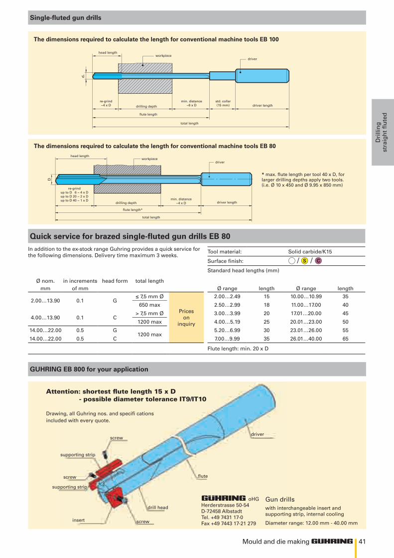
Single-fluted gun drills
oHG Herderstrasse 50-54 D-72458 Albstadt Tel. +49 7431 17-0 Fax +49 7443 17-21 279
drill head
flute
driver
screw
screw
screw
supporting strip
supporting strip
insert
with interchangeable insert andsupporting strip, internal cooling Diameter range: 12.00 mm - 40.00 mm
Gun drills
Drawing, all Guhring nos. and specifi cationsincluded with every quote.
attention: shortest flute length 15 x d - possible diameter tolerance it9/it10
The dimensions required to calculate the length for conventional machine tools EB 100
head length
total length
driverworkpiece
flute length
re-grind ~4 x D drilling depth
min. distance ~6 x D
std. collar (15 mm) driver length
Quick service for brazed single-fluted gun drills EB 80In addition to the ex-stock range Guhring provides a quick service forthe following dimensions. Delivery time maximum 3 weeks.
Tool material: Solid carbide/K15
Surface finish: Standard head lengths (mm)
Ø nom. in increments head form total lengthmm of mm Ø range length Ø range length
2.00…13.90 0.1 G≤ 7,5 mm Ø
Priceson
inquiry
2.00…2.49 15 10.00…10.99 35
650 max 2.50…2.99 18 11.00…17.00 40
4.00…13.90 0.1 C> 7,5 mm Ø 3.00…3.99 20 17.01…20.00 45
1200 max 4.00…5.19 25 20.01…23.00 50
14.00…22.00 0.5 G1200 max
5.20…6.99 30 23.01…26.00 55
14.00…22.00 0.5 C 7.00…9.99 35 26.01…40.00 65
Flute length: min. 20 x D
GUHRING EB 800 for your application
* max. flute length per tool 40 x D, for larger drilling depths apply two tools.(i.e. Ø 10 x 450 and Ø 9.95 x 850 mm)
head length
total length
driverworkpiece
flute length*
re-grind up to D 6 ~ 4 x D up to D 20 ~ 2 x D up to D 40 ~ 1 x D
drilling depthmin. distance
~4 x D driver length
The dimensions required to calculate the length for conventional machine tools EB 80
mould and die makingmillinG

44
400
300
200
100
0
0 0.5 1.0 1.5 2.0
400
300
200
100
0
0 0.5 1.0 1.5 2.0
RF 100 U • • • • • •RF 100 U/HF • • • • •RF 100 F • • • •RF 100 VA • • • •RF 100 VA/NF • • • •RF 100 A • •RF 100 A/WF • •RF 100 Ti • • •RF 100 H • • • •RF 100 SF • • • • • • • • • • •• •
35°
38°
Mould and die making
Millin
g
Milling
The cutting force comparison between a conventional milling cutter type N and a RF100 clearly shows the quieter, more rigid operation of the RF100.
Ff in
[N
]Ff
in [
N]
Milling length section [mm]
Type N
RF 100
Material(ISO-code)
Ste
el
Cas
t ir
on
Sta
inle
ss
stee
l
Alu
min
ium
Ti-
spec
ial
allo
ys
Har
den
ed
stee
l
Hardnesstensile strength
up t
o 85
0 N
/mm
2
abov
e 85
0 N
/mm
2
up t
o 18
0 H
B 3
0
abov
e 18
0 H
B 3
0
up t
o 75
0 N
/mm
2
abov
e 75
0 N
/mm
2
up t
o 3%
Si
abov
e 3
% S
i
Ti-b
ased
Ni-b
ased
up t
o 52
HR
C
abov
e 52
HR
C
= optimal suitability = limited suitability
RF 100 U - high-performance roughing end mills for materials up to 1600 N/mm2 (48 HRC)
RF 100 U high-performance end mills excel thanks to unequal helix angles which considerably reduce vibration. The uneven helix angle vastly improves surface quality with finishing operations and considerably higher feed rates with slot drilling and roughing operations are also achieved.
With many applications, the complete milling process can be covered with one RF 100, which as well as increasing tool life and dimensional accuracy of the workpiece generates a considerable cost advantage.
Summary of advantages• suitable for roughing and finishing• up to 60% higher feed rates• up to 4-times longer tool life• vibration-free operation• improved workpiece surface quality
with micro-corner protection for longer tool life
with neck clearance
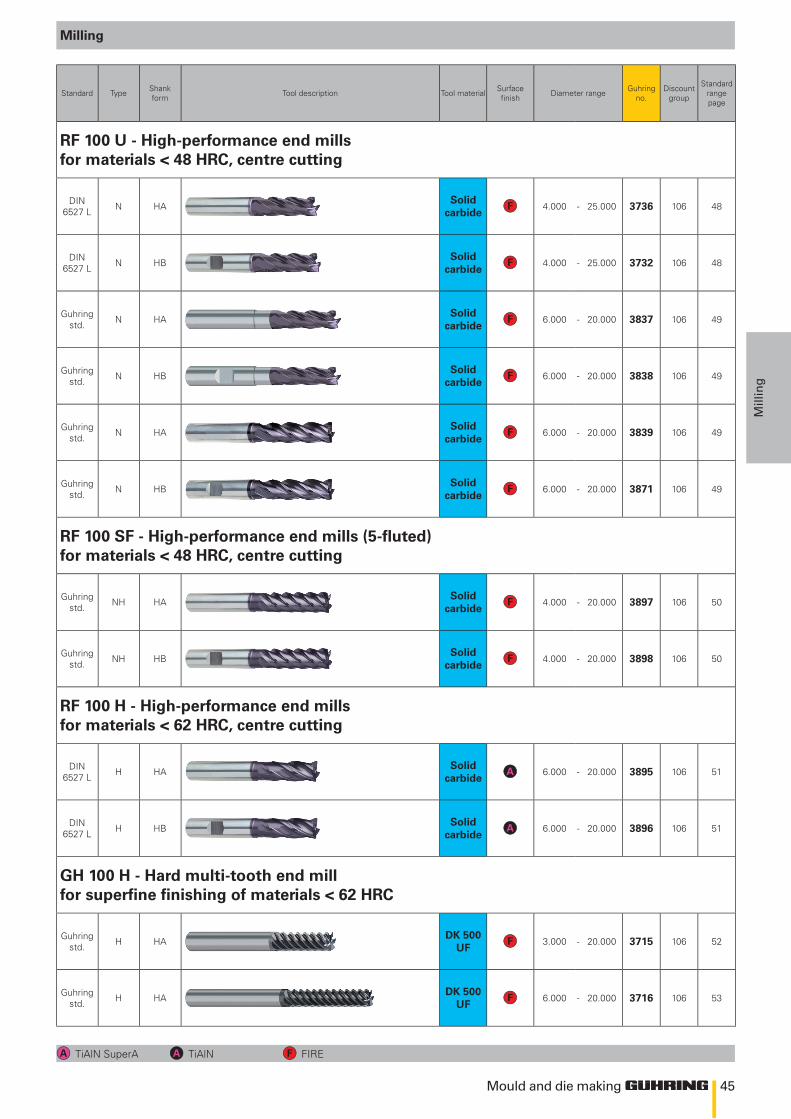
45
Mould and die making
Mill
ing
Standard Type Shankform Tool description Tool material Surface
finish Diameter range Guhring no.
Discount group
Standard rangepage
RF 100 U - High-performance end mills for materials < 48 HRC, centre cutting
DIN6527 L N HA
Solid carbide
4.000 - 25.000 3736 106 48
DIN6527 L N HB
Solid carbide
4.000 - 25.000 3732 106 48
Guhring std. N HA
Solid carbide
6.000 - 20.000 3837 106 49
Guhring std. N HB
Solid carbide
6.000 - 20.000 3838 106 49
Guhring std. N HA
Solid carbide
6.000 - 20.000 3839 106 49
Guhring std. N HB
Solid carbide
6.000 - 20.000 3871 106 49
RF 100 SF - High-performance end mills (5-fluted) for materials < 48 HRC, centre cutting
Guhring std. NH HA
Solid carbide
4.000 - 20.000 3897 106 50
Guhring std. NH HB
Solid carbide
4.000 - 20.000 3898 106 50
RF 100 H - High-performance end mills for materials < 62 HRC, centre cutting
DIN6527 L H HA
Solid carbide
6.000 - 20.000 3895 106 51
DIN6527 L H HB
Solid carbide
6.000 - 20.000 3896 106 51
GH 100 H - Hard multi-tooth end mill for superfine finishing of materials < 62 HRC
Guhring std. H HA
DK 500 UF
3.000 - 20.000 3715 106 52
Guhring std. H HA
DK 500 UF
6.000 - 20.000 3716 106 53
Milling
TiAlN SuperA TiAlN FIRE
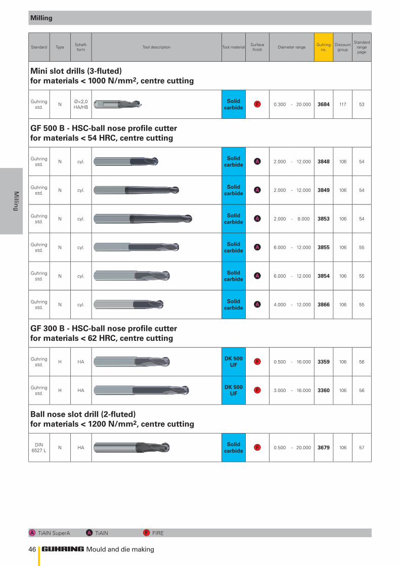
46
Mould and die making
Millin
g
Standard Type Schaft-form Tool description Tool material Surface
finish Diameter range Guhring no.
Discount group
Standard rangepage
Mini slot drills (3-fluted) for materials < 1000 N/mm2, centre cutting
Guhring std. N Ø<2,0
HA/HBSolid
carbide0.300 - 20.000 3684 117 53
GF 500 B - HSC-ball nose profile cutter for materials < 54 HRC, centre cutting
Guhring std. N cyl.
Solid carbide
2.000 - 12.000 3848 106 54
Guhring std. N cyl.
Solid carbide
2.000 - 12.000 3849 106 54
Guhring std. N cyl.
Solid carbide
2.000 - 8.000 3853 106 54
Guhring std. N cyl.
Solid carbide
6.000 - 12.000 3855 106 55
Guhring std. N cyl.
Solid carbide
6.000 - 12.000 3854 106 55
Guhring std. N cyl.
Solid carbide
4.000 - 12.000 3866 106 55
GF 300 B - HSC-ball nose profile cutter for materials < 62 HRC, centre cutting
Guhring std. H HA
DK 500 UF
0.500 - 16.000 3359 106 56
Guhring std. H HA
DK 500 UF
3.000 - 16.000 3360 106 56
Ball nose slot drill (2-fluted) for materials < 1200 N/mm2, centre cutting
DIN 6527 L N HA
Solid carbide
0.500 - 20.000 3679 106 57
Milling
TiAlN SuperA TiAlN FIRE
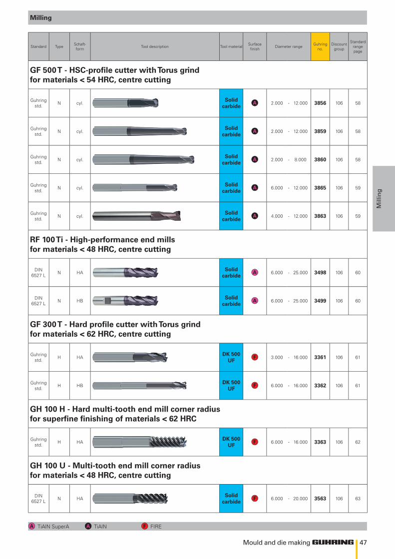
47
Mould and die making
Mill
ing
Standard Type Schaft-form Tool description Tool material Surface
finish Diameter range Guhring no.
Discount group
Standard rangepage
GF 500 T - HSC-profile cutter with Torus grind for materials < 54 HRC, centre cutting
Guhring std. N cyl.
Solid carbide
2.000 - 12.000 3856 106 58
Guhring std. N cyl.
Solid carbide
2.000 - 12.000 3859 106 58
Guhring std. N cyl.
Solid carbide
2.000 - 8.000 3860 106 58
Guhring std. N cyl.
Solid carbide
6.000 - 12.000 3865 106 59
Guhring std. N cyl.
Solid carbide
4.000 - 12.000 3863 106 59
RF 100 Ti - High-performance end mills for materials < 48 HRC, centre cutting
DIN6527 L N HA
Solid carbide
6.000 - 25.000 3498 106 60
DIN6527 L N HB
Solid carbide
6.000 - 25.000 3499 106 60
GF 300 T - Hard profile cutter with Torus grind for materials < 62 HRC, centre cutting
Guhring std. H HA
DK 500 UF
3.000 - 16.000 3361 106 61
Guhring std. H HB
DK 500 UF
6.000 - 16.000 3362 106 61
GH 100 H - Hard multi-tooth end mill corner radius for superfine finishing of materials < 62 HRC
Guhring std. H HA
DK 500 UF
6.000 - 16.000 3363 106 62
GH 100 U - Multi-tooth end mill corner radius for materials < 48 HRC, centre cutting
DIN6527 L N HA
Solid carbide
6.000 - 20.000 3563 106 63
Milling
TiAlN SuperA TiAlN FIRE
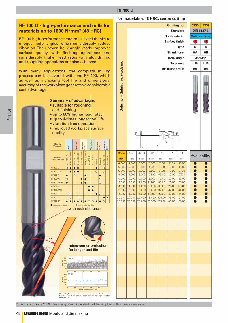
48
l2
l1
d1d2
l3
d3
400
300
200
100
0
0 0.5 1.0 1.5 2.0
400
300
200
100
0
0 0.5 1.0 1.5 2.0
RF 100 U • • • • • •RF 100 U/HF • • • • •RF 100 F • • • •RF 100 VA • • • •RF 100 VA/NF • • • •RF 100 A • •RF 100 A/WF • •RF 100 Ti • • •RF 100 H • • • •RF 100 SF • • • • • • • • • • •• •
35°
38°
Mould and die making
Millin
g
Ord
er n
o. =
Gu
hri
ng
no.
+ c
od
e n
o.
Guhring no. 3736 3732
Standard DIN 6527 L
Tool material Solid carbide
Surface finish
Type N N
Shank form HA HB
Helix angle 35°/38°
Tolerance h10 h10
Discount group 106 106
Code d1 h10 d2 h6 d3* l1 l2 l3Availability
no. mm mm mm mm mm mm
4,000 4.000 6.000 3.700 57.00 11.00 18.005,000 5.000 6.000 4.700 57.00 13.00 18.006,000 6.000 6.000 5.500 57.00 13.00 21.008,000 8.000 8.000 7.500 63.00 19.00 27.00
10,000 10.000 10.000 9.200 72.00 22.00 32.0012,000 12.000 12.000 11.200 83.00 26.00 38.0014,000 14.000 14.000 13.200 83.00 26.00 38.0016,000 16.000 16.000 15.000 92.00 32.00 44.0018,000 18.000 18.000 17.000 92.00 32.00 44.0020,000 20.000 20.000 19.000 104.00 38.00 54.0025,000 25.000 25.000 23.500 121.00 45.00 65.00
RF 100 U
for materials < 48 HRC, centre cutting
* technical change 2009: Remaining pre-change stock will be supplied without neck clearance
RF 100 U - high-performance end mills for materials up to 1600 N/mm2 (48 HRC)
The cutting force comparison between a conventional milling cutter type N and the RF 100 shows a clearly quieter, more rigid operation of the RF 100.
Ff in
[N
]Ff
in [
N]
Milling length section [mm]
Type N
RF 100
RF 100 high-performance end mills excel thanks to unequal helix angles which considerably reduce vibration. The uneven helix angle vastly improves surface quality with finshing operations and considerably higher feed rates with slot drilling and roughing operations are also achieved.
With many applications, the complete milling process can be covered with one RF 100, which as well as increasing tool life and dimensional accuracy of the workpiece generates a considerable cost advantage.
Material(ISO-code)
Ste
el
Cas
t ir
on
Sta
inle
ss
stee
l
Alu
min
ium
Ti-
spec
ial
allo
ys
Har
den
ed
stee
l
Hardnesstensile strength
up t
o 85
0 N
/mm
2
abov
e 85
0 N
/mm
2
up t
o 18
0 H
B 3
0
abov
e 18
0 H
B 3
0
up t
o 75
0 N
/mm
2
abov
e 75
0 N
/mm
2
up t
o 3%
Si
abov
e 3
% S
i
Ti-b
ased
Ni-b
ased
up t
o 52
HR
C
über
52
HR
C
= optimal suitability = limited suitability
micro-corner protection for longer tool life
with neck clearance
Summary of advantages• suitable for roughing and finishing• up to 60% higher feed rates• up to 4-times longer tool life• vibration-free operation• improved workpiece surface quality
l ll ll ll ll ll ll ll ll ll ll l
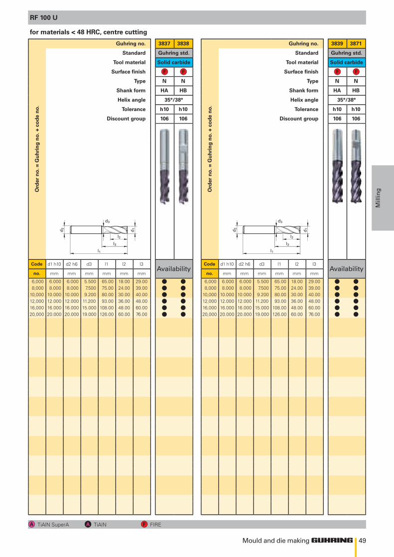
49
l2
l1
d1d2
l3
d3
l2
l1
d1d2
l3
d3
Mould and die making
Mill
ingO
rder
no.
= G
uh
rin
g n
o. +
co
de
no.
Guhring no. 3837 3838
Standard Guhring std.
Tool material Solid carbide
Surface finish
Type N N
Shank form HA HB
Helix angle 35°/38°
Tolerance h10 h10
Discount group 106 106
Code d1 h10 d2 h6 d3 l1 l2 l3Availability
no. mm mm mm mm mm mm
6,000 6.000 6.000 5.500 65.00 18.00 29.008,000 8.000 8.000 7.500 75.00 24.00 39.00
10,000 10.000 10.000 9.200 80.00 30.00 40.0012,000 12.000 12.000 11.200 93.00 36.00 48.0016,000 16.000 16.000 15.000 108.00 48.00 60.0020,000 20.000 20.000 19.000 126.00 60.00 76.00
Ord
er n
o. =
Gu
hri
ng
no.
+ c
od
e n
o.
Guhring no. 3839 3871
Standard Guhring std.
Tool material Solid carbide
Surface finish
Type N N
Shank form HA HB
Helix angle 35°/38°
Tolerance h10 h10
Discount group 106 106
Code d1 h10 d2 h6 d3 l1 l2 l3Availability
no. mm mm mm mm mm mm
6,000 6.000 6.000 5.500 65.00 18.00 29.008,000 8.000 8.000 7.500 75.00 24.00 39.00
10,000 10.000 10.000 9.200 80.00 30.00 40.0012,000 12.000 12.000 11.200 93.00 36.00 48.0016,000 16.000 16.000 15.000 108.00 48.00 60.0020,000 20.000 20.000 19.000 126.00 60.00 76.00
RF 100 U
TiAlN SuperA TiAlN FIRE
for materials < 48 HRC, centre cutting
l ll ll ll ll ll l
l ll ll ll ll ll l
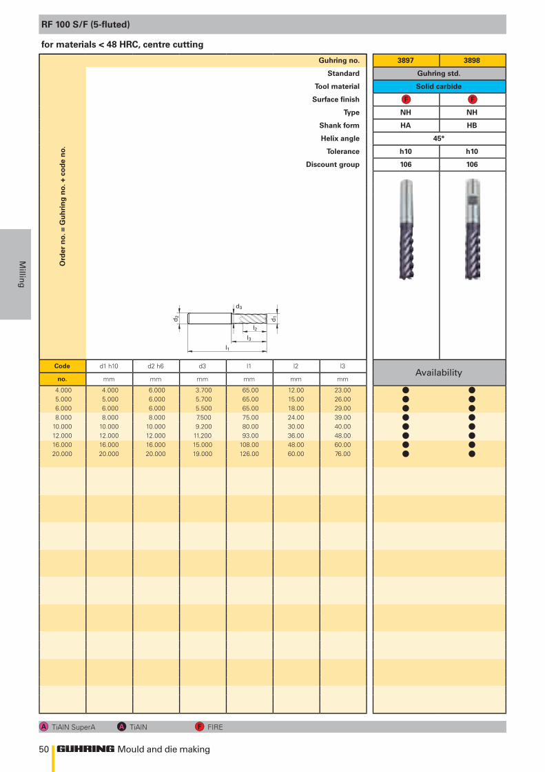
50
l2
l1
d1d2
l3
d3
Mould and die making
Millin
g
Ord
er n
o. =
Gu
hri
ng
no.
+ c
od
e n
o.Guhring no. 3897 3898
Standard Guhring std.
Tool material Solid carbide
Surface finish
Type NH NH
Shank form HA HB
Helix angle 45°
Tolerance h10 h10
Discount group 106 106
Code d1 h10 d2 h6 d3 l1 l2 l3Availability
no. mm mm mm mm mm mm
4.000 4.000 6.000 3.700 65.00 12.00 23.005.000 5.000 6.000 5.700 65.00 15.00 26.006.000 6.000 6.000 5.500 65.00 18.00 29.008.000 8.000 8.000 7.500 75.00 24.00 39.00
10.000 10.000 10.000 9.200 80.00 30.00 40.0012.000 12.000 12.000 11.200 93.00 36.00 48.0016.000 16.000 16.000 15.000 108.00 48.00 60.0020.000 20.000 20.000 19.000 126.00 60.00 76.00
RF 100 S/F (5-fluted)
TiAlN SuperA TiAlN FIRE
for materials < 48 HRC, centre cutting
l ll ll ll ll ll ll ll l
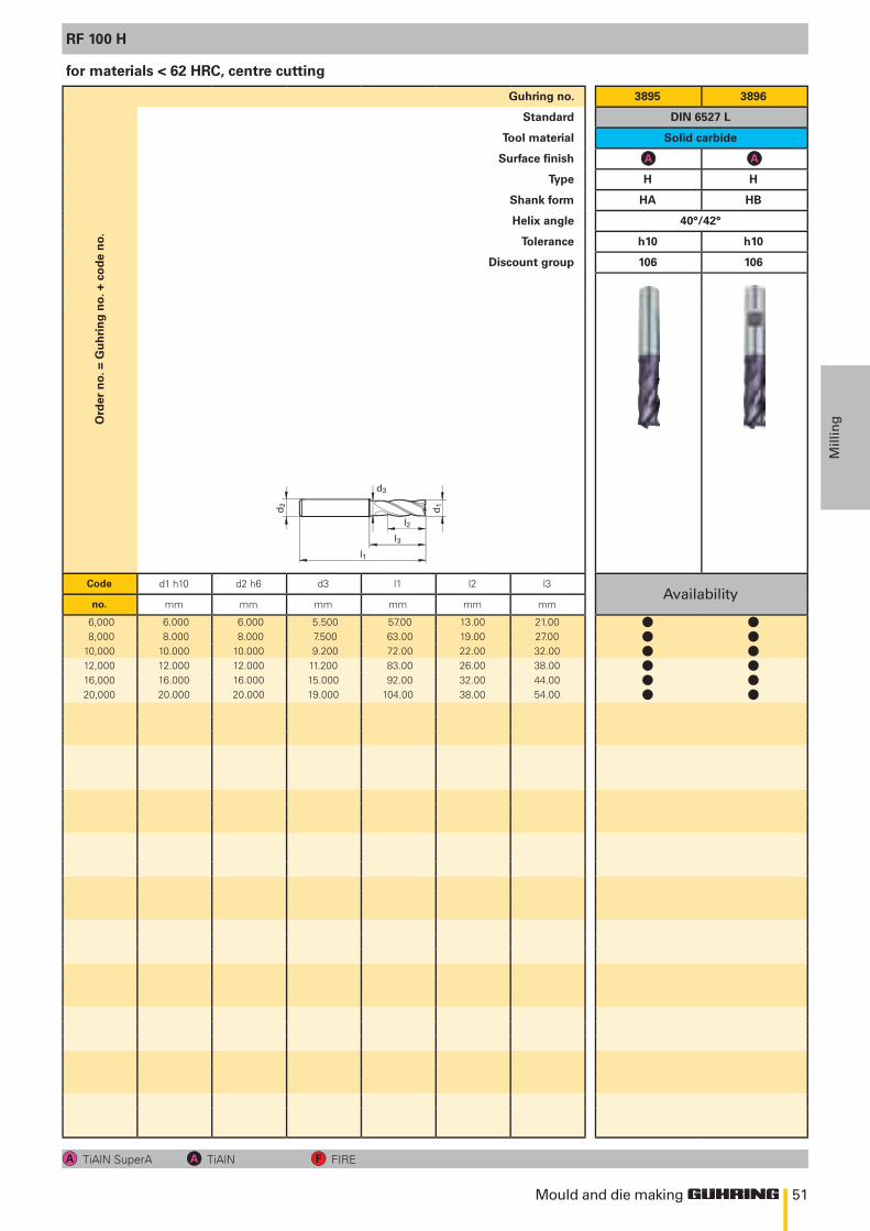
51
l2
l1
d1d2
l3
d3
Mould and die making
Mill
ingO
rder
no.
= G
uh
rin
g n
o. +
co
de
no.
Guhring no. 3895 3896
Standard DIN 6527 L
Tool material Solid carbide
Surface finish
Type H H
Shank form HA HB
Helix angle 40°/42°
Tolerance h10 h10
Discount group 106 106
Code d1 h10 d2 h6 d3 l1 l2 l3Availability
no. mm mm mm mm mm mm
6,000 6.000 6.000 5.500 57.00 13.00 21.008,000 8.000 8.000 7.500 63.00 19.00 27.00
10,000 10.000 10.000 9.200 72.00 22.00 32.0012,000 12.000 12.000 11.200 83.00 26.00 38.0016,000 16.000 16.000 15.000 92.00 32.00 44.0020,000 20.000 20.000 19.000 104.00 38.00 54.00
RF 100 H
TiAlN SuperA TiAlN FIRE
for materials < 62 HRC, centre cutting
l ll ll ll ll ll l
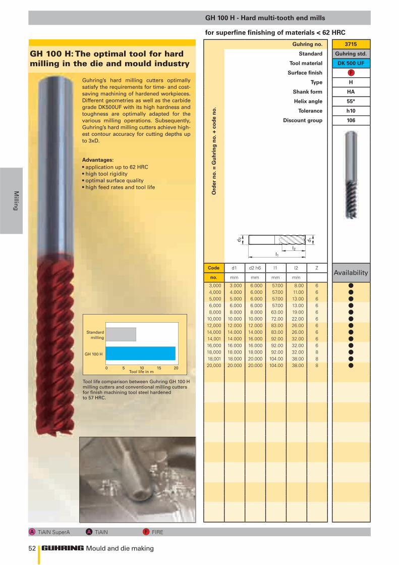
52
l2
l1
d1 d2
Mould and die making
Millin
g
Ord
er n
o. =
Gu
hri
ng
no.
+ c
od
e n
o.
Guhring no. 3715
Standard Guhring std.
Tool material DK 500 UF
Surface finish
Type H
Shank form HA
Helix angle 55°
Tolerance h10
Discount group 106
Code d1 d2 h6 l1 l2 ZAvailability
no. mm mm mm mm
3,000 3.000 6.000 57.00 8.00 64,000 4.000 6.000 57.00 11.00 65,000 5.000 6.000 57.00 13.00 66,000 6.000 6.000 57.00 13.00 68,000 8.000 8.000 63.00 19.00 6
10,000 10.000 10.000 72.00 22.00 612,000 12.000 12.000 83.00 26.00 614,000 14.000 14.000 83.00 26.00 614,001 14.000 16.000 92.00 32.00 616,000 16.000 16.000 92.00 32.00 618,000 18.000 18.000 92.00 32.00 818,001 18.000 20.000 104.00 38.00 820,000 20.000 20.000 104.00 38.00 8
GH 100 H - Hard multi-tooth end mills
TiAlN SuperA TiAlN FIRE
for superfine finishing of materials < 62 HRC
Guhring’s hard milling cutters optimally satisfy the requirements for time- and cost-saving machining of hardened workpieces. Different geometries as well as the carbide grade DK500UF with its high hardness and toughness are optimally adapted for the various milling operations. Subsequently, Guhring’s hard milling cutters achieve high-est contour accuracy for cutting depths up to 3xD.
• application up to 62 HRC• high tool rigidity• optimal surface quality• high feed rates and tool life
Gh 100 h: the optimal tool for hard milling in the die and mould industry
Tool life comparison between Guhring GH 100 H milling cutters and conventional milling cutters for finish machining tool steel hardened to 57 HRC.
Advantages:
0 5 10 15 20Tool life in m
Standard milling
GH 100 H
lllllllllllll
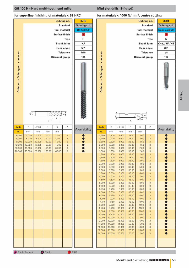
53
l2
l1
d1 d2
l2l1
d1
d2
Mould and die making
Mill
ingO
rder
no.
= G
uh
rin
g n
o. +
co
de
no.
Guhring no. 3716
Standard Guhring std.
Tool material DK 500 UF
Surface finish
Type H
Shank form HA
Helix angle 55°
Tolerance h10
Discount group 106
Code d1 d2 h6 l1 l2 ZAvailability
no. mm mm mm mm
6,000 6.000 6.000 75.00 30.00 68,000 8.000 8.000 100.00 40.00 6
10,000 10.000 10.000 100.00 40.00 612,000 12.000 12.000 150.00 45.00 616,000 16.000 16.000 150.00 65.00 620,000 20.000 20.000 150.00 65.00 8
GH 100 H - Hard multi-tooth end mills
for superfine finishing of materials < 62 HRC
Ord
er n
o. =
Gu
hri
ng
no.
+ c
od
e n
o.
Guhring no. 3684
Standard Guhring std.
Tool material Solid carbide
Surface finish
Type N
Shank form Ø<2,0 HA/HB
Helix angle 30°
Tolerance e8
Discount group 117
Code d1 d2 h6 l1 l2 ZAvailability
no. mm mm mm mm
0,300 0.300 3.000 38.00 1.00 30,400 0.400 3.000 38.00 1.00 30,500 0.500 3.000 38.00 1.50 30,600 0.600 3.000 38.00 1.50 30,800 0.800 3.000 38.00 2.00 31,000 1.000 3.000 38.00 2.00 31,200 1.200 3.000 38.00 2.00 31,500 1.500 3.000 38.00 2.00 31,800 1.800 3.000 38.00 2.00 32,000 2.000 6.000 38.00 4.00 32,500 2.500 6.000 38.00 5.00 33,000 3.000 6.000 38.00 5.00 33,500 3.500 6.000 38.00 6.00 34,000 4.000 6.000 38.00 7.00 34,500 4.500 6.000 38.00 8.00 35,000 5.000 6.000 38.00 8.00 35,500 5.500 6.000 38.00 8.00 35,750 5.750 6.000 38.00 8.00 36,000 6.000 6.000 38.00 8.00 36,750 6.750 8.000 42.00 10.00 37,000 7.000 8.000 42.00 10.00 37,750 7.750 8.000 42.00 10.00 38,000 8.000 8.000 43.00 11.00 38,700 8.700 10.000 48.00 11.00 39,000 9.000 10.000 48.00 11.00 39,700 9.700 10.000 48.00 11.00 3
10,000 10.000 10.000 50.00 13.00 312,000 12.000 12.000 55.00 15.00 314,000 14.000 14.000 58.00 15.00 316,000 16.000 16.000 62.00 18.00 318,000 18.000 18.000 70.00 20.00 320,000 20.000 20.000 75.00 22.00 3
Mini slot drills (3-fluted)
TiAlN SuperA TiAlN FIRE
for materials < 1000 N/mm2, centre cutting
llllll
llllllllllllllllllllllllllllllll
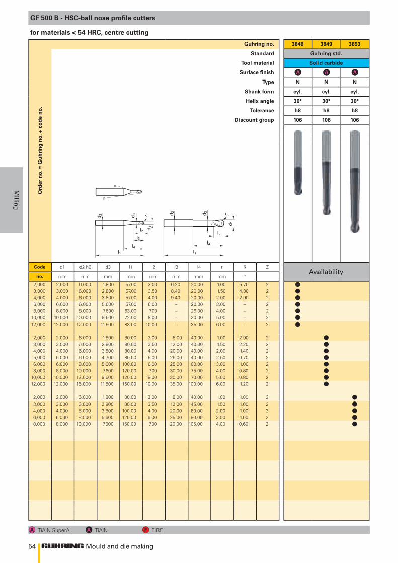
54
l2 d1
d2
l4l1
d3 r
l3l2
d1
d2
l4
l1
d3
r
α
β
Mould and die making
Millin
g
Ord
er n
o. =
Gu
hri
ng
no.
+ c
od
e n
o.Guhring no. 3848 3849 3853
Standard Guhring std.
Tool material Solid carbide
Surface finish
Type N N N
Shank form cyl. cyl. cyl.
Helix angle 30° 30° 30°
Tolerance h8 h8 h8
Discount group 106 106 106
Code d1 d2 h6 d3 l1 l2 l3 l4 r ZAvailability
no. mm mm mm mm mm mm mm mm °
2,000 2.000 6.000 1.800 57.00 3.00 6.20 20.00 1.00 5.70 23,000 3.000 6.000 2.800 57.00 3.50 8.40 20.00 1.50 4.30 24,000 4.000 6.000 3.800 57.00 4.00 9.40 20.00 2.00 2.90 26,000 6.000 6.000 5.600 57.00 6.00 – 20.00 3.00 – 28,000 8.000 8.000 7.600 63.00 7.00 – 26.00 4.00 – 2
10,000 10.000 10.000 9.600 72.00 8.00 – 30.00 5.00 – 212,000 12.000 12.000 11.500 83.00 10.00 – 35.00 6.00 – 2
2,000 2.000 6.000 1.800 80.00 3.00 8.00 40.00 1.00 2.90 23,000 3.000 6.000 2.800 80.00 3.50 12.00 40.00 1.50 2.20 24,000 4.000 6.000 3.800 80.00 4.00 20.00 40.00 2.00 1.40 25,000 5.000 6.000 4.700 80.00 5.00 25.00 40.00 2.50 0.70 26,000 6.000 8.000 5.600 100.00 6.00 25.00 60.00 3.00 1.00 28,000 8.000 10.000 7.600 120.00 7.00 30.00 75.00 4.00 0.80 2
10,000 10.000 12.000 9.600 120.00 8.00 30.00 70.00 5.00 0.80 212,000 12.000 16.000 11.500 150.00 10.00 35.00 100.00 6.00 1.20 2
2,000 2.000 6.000 1.800 80.00 3.00 8.00 40.00 1.00 1.00 23,000 3.000 6.000 2.800 80.00 3.50 12.00 45.00 1.50 1.00 24,000 4.000 6.000 3.800 100.00 4.00 20.00 60.00 2.00 1.00 26,000 6.000 8.000 5.600 120.00 6.00 25.00 80.00 3.00 1.00 28,000 8.000 10.000 7.600 150.00 7.00 20.00 105.00 4.00 0.60 2
GF 500 B - HSC-ball nose profile cutters
TiAlN SuperA TiAlN FIRE
for materials < 54 HRC, centre cutting
lllllll
llllllll
lllll
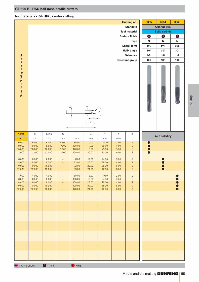
55
l2
d1
d2
l4
l1
d3
r
Mould and die making
Mill
ingO
rder
no.
= G
uh
rin
g n
o. +
co
de
no.
Guhring no. 3855 3854 3866
Standard Guhring std.
Tool material Solid carbide
Surface finish
Type N N N
Shank form cyl. cyl. cyl.
Helix angle 30° 30° 30°
Tolerance h8 h8 h8
Discount group 106 106 106
Code d1 d2 h6 d3 l1 l2 l4 r ZAvailability
no. mm mm mm mm mm mm mm
6,000 6.000 6.000 5.600 80.00 6.00 40.00 3.00 28,000 8.000 8.000 7.600 100.00 7.00 60.00 4.00 2
10,000 10.000 10.000 9.600 120.00 8.00 75.00 5.00 212,000 12.000 12.000 11.500 120.00 10.00 70.00 6.00 2
6,000 6.000 6.000 – 57.00 12.00 24.00 3.00 28,000 8.000 8.000 – 63.00 16.00 29.00 4.00 2
10,000 10.000 10.000 – 72.00 20.00 35.00 5.00 212,000 12.000 12.000 – 83.00 24.00 42.00 6.00 2
4,000 4.000 4.000 – 80.00 8.00 17.50 2.00 26,000 6.000 6.000 – 100.00 12.00 24.00 3.00 28,000 8.000 8.000 – 100.00 16.00 29.00 4.00 2
10,000 10.000 10.000 – 100.00 20.00 35.00 5.00 212,000 12.000 12.000 – 120.00 24.00 42.00 6.00 2
GF 500 B - HSC-ball nose profile cutters
TiAlN SuperA TiAlN FIRE
for materials < 54 HRC, centre cutting
llll
llll
lllll
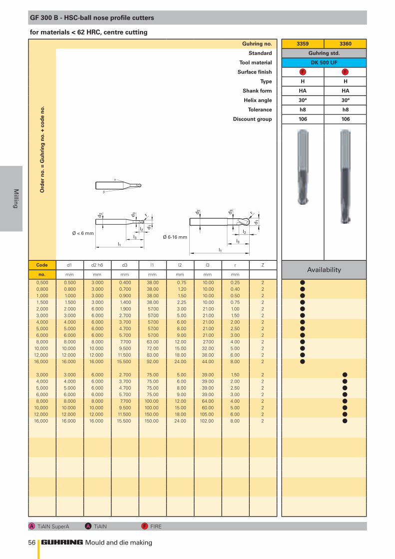
56
l2 d1
d2
l3l1
d3 r
Ø 6-16 mmØ < 6 mm l2
d1
d2
l3
l1
d3
r
α
β
Mould and die making
Millin
g
Ord
er n
o. =
Gu
hri
ng
no.
+ c
od
e n
o.Guhring no. 3359 3360
Standard Guhring std.
Tool material DK 500 UF
Surface finish
Type H H
Shank form HA HA
Helix angle 30° 30°
Tolerance h8 h8
Discount group 106 106
Code d1 d2 h6 d3 l1 l2 l3 r ZAvailability
no. mm mm mm mm mm mm mm
0,500 0.500 3.000 0.400 38.00 0.75 10.00 0.25 20,800 0.800 3.000 0.700 38.00 1.20 10.00 0.40 21,000 1.000 3.000 0.900 38.00 1.50 10.00 0.50 21,500 1.500 3.000 1.400 38.00 2.25 10.00 0.75 22,000 2.000 6.000 1.900 57.00 3.00 21.00 1.00 23,000 3.000 6.000 2.700 57.00 5.00 21.00 1.50 24,000 4.000 6.000 3.700 57.00 6.00 21.00 2.00 25,000 5.000 6.000 4.700 57.00 8.00 21.00 2.50 26,000 6.000 6.000 5.700 57.00 9.00 21.00 3.00 28,000 8.000 8.000 7.700 63.00 12.00 27.00 4.00 2
10,000 10.000 10.000 9.500 72.00 15.00 32.00 5.00 212,000 12.000 12.000 11.500 83.00 18.00 38.00 6.00 216,000 16.000 16.000 15.500 92.00 24.00 44.00 8.00 2
3,000 3.000 6.000 2.700 75.00 5.00 39.00 1.50 24,000 4.000 6.000 3.700 75.00 6.00 39.00 2.00 25,000 5.000 6.000 4.700 75.00 8.00 39.00 2.50 26,000 6.000 6.000 5.700 75.00 9.00 39.00 3.00 28,000 8.000 8.000 7.700 100.00 12.00 64.00 4.00 2
10,000 10.000 10.000 9.500 100.00 15.00 60.00 5.00 212,000 12.000 12.000 11.500 150.00 18.00 105.00 6.00 216,000 16.000 16.000 15.500 150.00 24.00 102.00 8.00 2
GF 300 B - HSC-ball nose profile cutters
TiAlN SuperA TiAlN FIRE
for materials < 62 HRC, centre cutting
lllllllllllll
llllllll
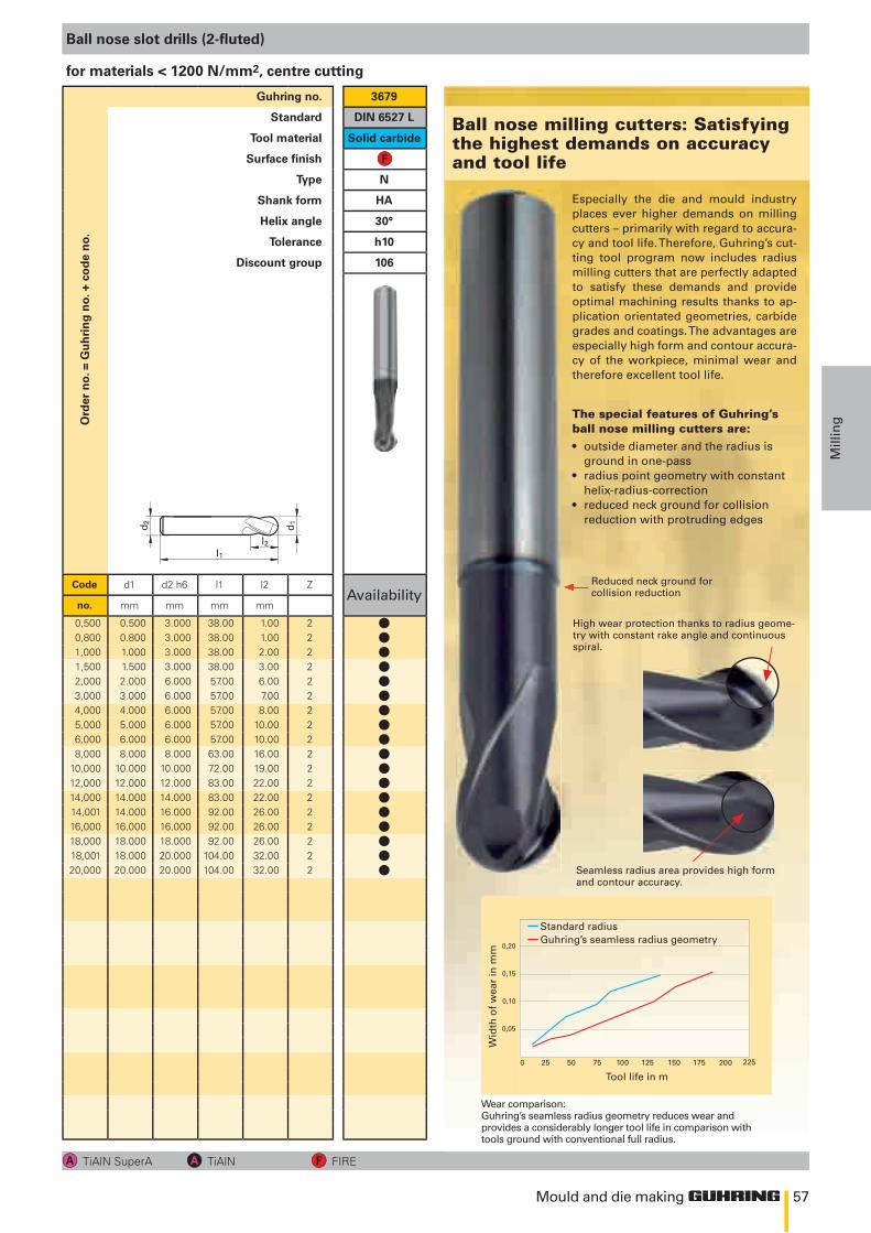
57
l2l1
d1d2
0 25 50 75 100 125 150 175 200
0,20
0,15
0,10
0,05
225
Mould and die making
Mill
ingO
rder
no.
= G
uh
rin
g n
o. +
co
de
no.
Guhring no. 3679
Standard DIN 6527 L
Tool material Solid carbide
Surface finish
Type N
Shank form HA
Helix angle 30°
Tolerance h10
Discount group 106
Code d1 d2 h6 l1 l2 ZAvailability
no. mm mm mm mm
0,500 0.500 3.000 38.00 1.00 20,800 0.800 3.000 38.00 1.00 21,000 1.000 3.000 38.00 2.00 21,500 1.500 3.000 38.00 3.00 22,000 2.000 6.000 57.00 6.00 23,000 3.000 6.000 57.00 7.00 24,000 4.000 6.000 57.00 8.00 25,000 5.000 6.000 57.00 10.00 26,000 6.000 6.000 57.00 10.00 28,000 8.000 8.000 63.00 16.00 2
10,000 10.000 10.000 72.00 19.00 212,000 12.000 12.000 83.00 22.00 214,000 14.000 14.000 83.00 22.00 214,001 14.000 16.000 92.00 26.00 216,000 16.000 16.000 92.00 26.00 218,000 18.000 18.000 92.00 26.00 218,001 18.000 20.000 104.00 32.00 220,000 20.000 20.000 104.00 32.00 2
Ball nose slot drills (2-fluted)
TiAlN SuperA TiAlN FIRE
for materials < 1200 N/mm2, centre cutting
Especially the die and mould industry places ever higher demands on milling cutters – primarily with regard to accura-cy and tool life. Therefore, Guhring’s cut-ting tool program now includes radius milling cutters that are perfectly adapted to satisfy these demands and provide optimal machining results thanks to ap-plication orientated geometries, carbide grades and coatings. The advantages are especially high form and contour accura-cy of the workpiece, minimal wear and therefore excellent tool life.
Reduced neck ground for collision reduction
Wear comparison: Guhring’s seamless radius geometry reduces wear and provides a considerably longer tool life in comparison with tools ground with conventional full radius.
Tool life in m
Wid
th o
f w
ear
in m
m
Standard radiusGuhring’s seamless radius geometry
High wear protection thanks to radius geome-try with constant rake angle and continuous spiral.
Seamless radius area provides high form and contour accuracy.
• outside diameter and the radius is ground in one-pass• radius point geometry with constant helix-radius-correction• reduced neck ground for collision reduction with protruding edges
the special features of Guhring’s ball nose milling cutters are:
Ball nose milling cutters: satisfying the highest demands on accuracy and tool life
llllllllllllllllll
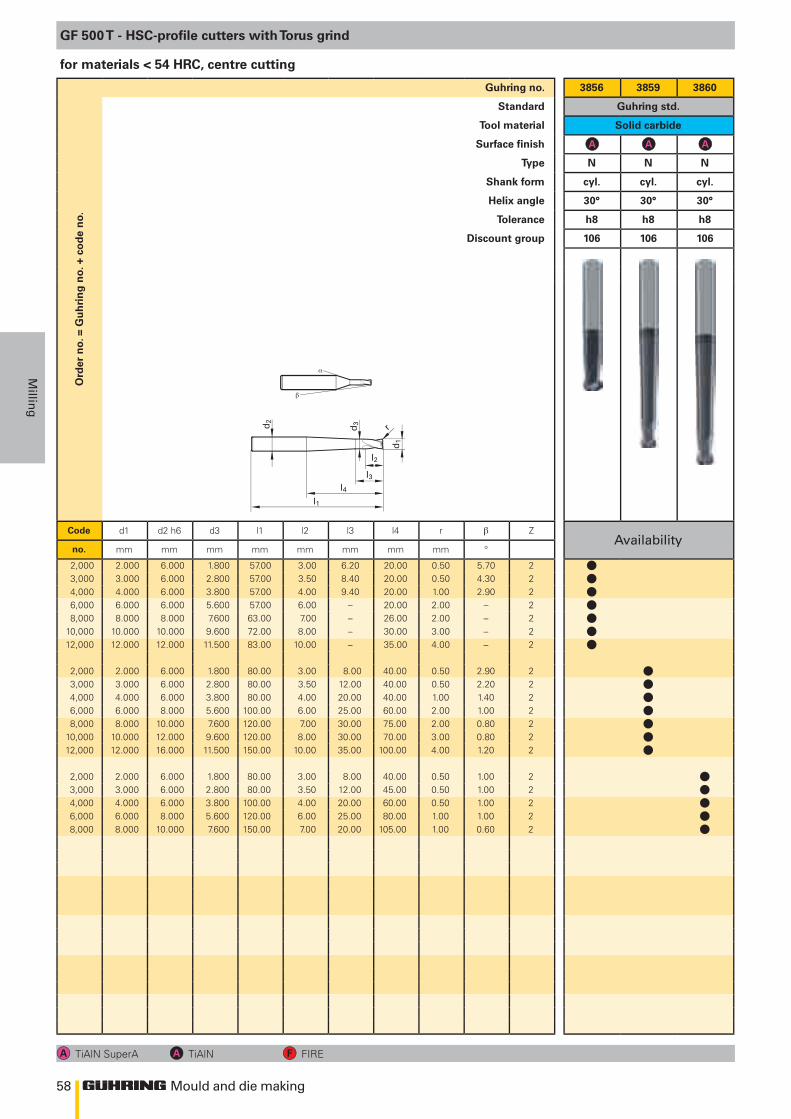
58
l3
d2
l4l1
d3
d1
r
l2
α
β
Mould and die making
Millin
g
Ord
er n
o. =
Gu
hri
ng
no.
+ c
od
e n
o.Guhring no. 3856 3859 3860
Standard Guhring std.
Tool material Solid carbide
Surface finish
Type N N N
Shank form cyl. cyl. cyl.
Helix angle 30° 30° 30°
Tolerance h8 h8 h8
Discount group 106 106 106
Code d1 d2 h6 d3 l1 l2 l3 l4 r ZAvailability
no. mm mm mm mm mm mm mm mm °
2,000 2.000 6.000 1.800 57.00 3.00 6.20 20.00 0.50 5.70 23,000 3.000 6.000 2.800 57.00 3.50 8.40 20.00 0.50 4.30 24,000 4.000 6.000 3.800 57.00 4.00 9.40 20.00 1.00 2.90 26,000 6.000 6.000 5.600 57.00 6.00 – 20.00 2.00 – 28,000 8.000 8.000 7.600 63.00 7.00 – 26.00 2.00 – 2
10,000 10.000 10.000 9.600 72.00 8.00 – 30.00 3.00 – 212,000 12.000 12.000 11.500 83.00 10.00 – 35.00 4.00 – 2
2,000 2.000 6.000 1.800 80.00 3.00 8.00 40.00 0.50 2.90 23,000 3.000 6.000 2.800 80.00 3.50 12.00 40.00 0.50 2.20 24,000 4.000 6.000 3.800 80.00 4.00 20.00 40.00 1.00 1.40 26,000 6.000 8.000 5.600 100.00 6.00 25.00 60.00 2.00 1.00 28,000 8.000 10.000 7.600 120.00 7.00 30.00 75.00 2.00 0.80 2
10,000 10.000 12.000 9.600 120.00 8.00 30.00 70.00 3.00 0.80 212,000 12.000 16.000 11.500 150.00 10.00 35.00 100.00 4.00 1.20 2
2,000 2.000 6.000 1.800 80.00 3.00 8.00 40.00 0.50 1.00 23,000 3.000 6.000 2.800 80.00 3.50 12.00 45.00 0.50 1.00 24,000 4.000 6.000 3.800 100.00 4.00 20.00 60.00 0.50 1.00 26,000 6.000 8.000 5.600 120.00 6.00 25.00 80.00 1.00 1.00 28,000 8.000 10.000 7.600 150.00 7.00 20.00 105.00 1.00 0.60 2
GF 500 T - HSC-profile cutters with Torus grind
TiAlN SuperA TiAlN FIRE
for materials < 54 HRC, centre cutting
lllllll
lllllll
lllll
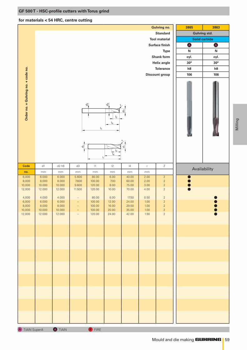
59
l2
d1
d2
l4
l1
d3
r
l2
l1
d1 d2
r
l4
Mould and die making
Mill
ingO
rder
no.
= G
uh
rin
g n
o. +
co
de
no.
Guhring no. 3865 3863
Standard Guhring std.
Tool material Solid carbide
Surface finish
Type N N
Shank form cyl. cyl.
Helix angle 30° 30°
Tolerance h8 h8
Discount group 106 106
Code d1 d2 h6 d3 l1 l2 l4 r ZAvailability
no. mm mm mm mm mm mm mm
6,000 6.000 6.000 5.600 80.00 6.00 40.00 2.00 28,000 8.000 8.000 7.600 100.00 7.00 60.00 2.00 2
10,000 10.000 10.000 9.600 120.00 8.00 75.00 3.00 212,000 12.000 12.000 11.500 120.00 10.00 70.00 4.00 2
4,000 4.000 4.000 – 80.00 8.00 17.50 0.50 26,000 6.000 6.000 – 100.00 12.00 24.00 1.00 28,000 8.000 8.000 – 100.00 16.00 29.00 1.00 2
10,000 10.000 10.000 – 100.00 20.00 35.00 1.00 212,000 12.000 12.000 – 120.00 24.00 42.00 1.50 2
GF 500 T - HSC-profile cutters with Torus grind
TiAlN SuperA TiAlN FIRE
for materials < 54 HRC, centre cutting
llll
lllll
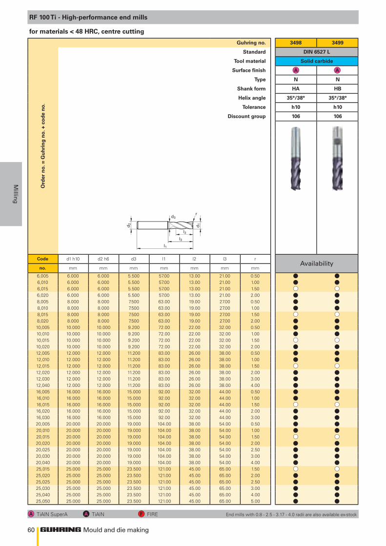
60
l2
l1
d1d2
l3
d3r
Mould and die making
Millin
g
Ord
er n
o. =
Gu
hri
ng
no.
+ c
od
e n
o.Guhring no. 3498 3499
Standard DIN 6527 L
Tool material Solid carbide
Surface finish
Type N N
Shank form HA HB
Helix angle 35°/38° 35°/38°
Tolerance h10 h10
Discount group 106 106
Code d1 h10 d2 h6 d3 l1 l2 l3 rAvailability
no. mm mm mm mm mm mm mm
6,005 6.000 6.000 5.500 57.00 13.00 21.00 0.506,010 6.000 6.000 5.500 57.00 13.00 21.00 1.006,015 6.000 6.000 5.500 57.00 13.00 21.00 1.506,020 6.000 6.000 5.500 57.00 13.00 21.00 2.008,005 8.000 8.000 7.500 63.00 19.00 27.00 0.508,010 8.000 8.000 7.500 63.00 19.00 27.00 1.008,015 8.000 8.000 7.500 63.00 19.00 27.00 1.508,020 8.000 8.000 7.500 63.00 19.00 27.00 2.0010,005 10.000 10.000 9.200 72.00 22.00 32.00 0.5010,010 10.000 10.000 9.200 72.00 22.00 32.00 1.0010,015 10.000 10.000 9.200 72.00 22.00 32.00 1.5010,020 10.000 10.000 9.200 72.00 22.00 32.00 2.0012,005 12.000 12.000 11.200 83.00 26.00 38.00 0.5012,010 12.000 12.000 11.200 83.00 26.00 38.00 1.0012,015 12.000 12.000 11.200 83.00 26.00 38.00 1.5012,020 12.000 12.000 11.200 83.00 26.00 38.00 2.0012,030 12.000 12.000 11.200 83.00 26.00 38.00 3.0012,040 12.000 12.000 11.200 83.00 26.00 38.00 4.0016,005 16.000 16.000 15.000 92.00 32.00 44.00 0.5016,010 16.000 16.000 15.000 92.00 32.00 44.00 1.0016,015 16.000 16.000 15.000 92.00 32.00 44.00 1.5016,020 16.000 16.000 15.000 92.00 32.00 44.00 2.0016,030 16.000 16.000 15.000 92.00 32.00 44.00 3.0020,005 20.000 20.000 19.000 104.00 38.00 54.00 0.5020,010 20.000 20.000 19.000 104.00 38.00 54.00 1.0020,015 20.000 20.000 19.000 104.00 38.00 54.00 1.5020,020 20.000 20.000 19.000 104.00 38.00 54.00 2.0020,025 20.000 20.000 19.000 104.00 38.00 54.00 2.5020,030 20.000 20.000 19.000 104.00 38.00 54.00 3.0020,040 20.000 20.000 19.000 104.00 38.00 54.00 4.0025,015 25.000 25.000 23.500 121.00 45.00 65.00 1.5025,020 25.000 25.000 23.500 121.00 45.00 65.00 2.0025,025 25.000 25.000 23.500 121.00 45.00 65.00 2.5025,030 25.000 25.000 23.500 121.00 45.00 65.00 3.0025,040 25.000 25.000 23.500 121.00 45.00 65.00 4.0025,050 25.000 25.000 23.500 121.00 45.00 65.00 5.00
RF 100 Ti - High-performance end mills
TiAlN SuperA TiAlN FIRE
for materials < 48 HRC, centre cutting
End mills with 0.8 - 2.5 - 3.17 - 4.0 radii are also available ex-stock
l ll l
l ll ll l
l ll ll l
l ll ll l
l ll ll ll ll l
l ll ll ll l
l ll ll ll l
l ll ll ll ll l
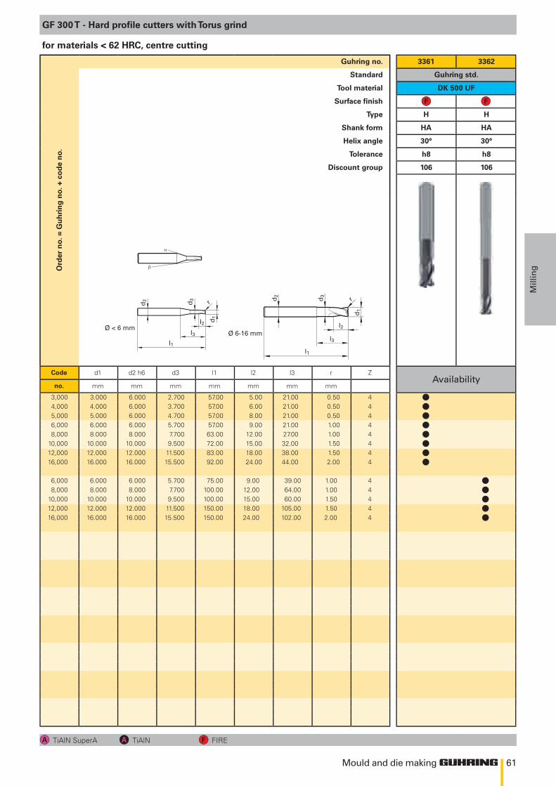
61
l2 d1
d2
l3l1
d3 r
Ø 6-16 mmØ < 6 mm l2
d1
d2
l3
l1
d3
r
α
β
Mould and die making
Mill
ingO
rder
no.
= G
uh
rin
g n
o. +
co
de
no.
Guhring no. 3361 3362
Standard Guhring std.
Tool material DK 500 UF
Surface finish
Type H H
Shank form HA HA
Helix angle 30° 30°
Tolerance h8 h8
Discount group 106 106
Code d1 d2 h6 d3 l1 l2 l3 r ZAvailability
no. mm mm mm mm mm mm mm
3,000 3.000 6.000 2.700 57.00 5.00 21.00 0.50 44,000 4.000 6.000 3.700 57.00 6.00 21.00 0.50 45,000 5.000 6.000 4.700 57.00 8.00 21.00 0.50 46,000 6.000 6.000 5.700 57.00 9.00 21.00 1.00 48,000 8.000 8.000 7.700 63.00 12.00 27.00 1.00 4
10,000 10.000 10.000 9.500 72.00 15.00 32.00 1.50 412,000 12.000 12.000 11.500 83.00 18.00 38.00 1.50 416,000 16.000 16.000 15.500 92.00 24.00 44.00 2.00 4
6,000 6.000 6.000 5.700 75.00 9.00 39.00 1.00 48,000 8.000 8.000 7.700 100.00 12.00 64.00 1.00 4
10,000 10.000 10.000 9.500 100.00 15.00 60.00 1.50 412,000 12.000 12.000 11.500 150.00 18.00 105.00 1.50 416,000 16.000 16.000 15.500 150.00 24.00 102.00 2.00 4
GF 300 T - Hard profile cutters with Torus grind
TiAlN SuperA TiAlN FIRE
for materials < 62 HRC, centre cutting
llllllll
lllll
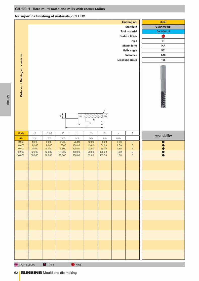
62
l2l3
d1 d2
l1
d3
r
Mould and die making
Millin
g
Ord
er n
o. =
Gu
hri
ng
no.
+ c
od
e n
o.Guhring no. 3363
Standard Guhring std.
Tool material DK 500 UF
Surface finish
Type H
Shank form HA
Helix angle 55°
Tolerance h10
Discount group 106
Code d1 d2 h6 d3 l1 l2 l3 r ZAvailability
no. mm mm mm mm mm mm mm
6,000 6.000 6.000 5.700 75.00 13.00 39.00 0.50 68,000 8.000 8.000 7.700 100.00 19.00 64.00 0.50 6
10,000 10.000 10.000 9.500 100.00 22.00 60.00 0.50 612,000 12.000 12.000 11.500 150.00 26.00 105.00 1.00 616,000 16.000 16.000 15.500 150.00 32.00 102.00 1.00 6
GH 100 H - Hard multi-tooth end mills with corner radius
TiAlN SuperA TiAlN FIRE
for superfine finishing of materials < 62 HRC
lllll
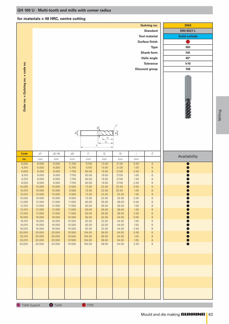
63
l1
d1
d2
l2
r
d3
l3
Mould and die making
Mill
ingO
rder
no.
= G
uh
rin
g n
o. +
co
de
no.
Guhring no. 3563
Standard DIN 6527 L
Tool material Solid carbide
Surface finish
Type NH
Shank form HA
Helix angle 45°
Tolerance h10
Discount group 106
Code d1 d2 h6 d3 l1 l2 l3 r ZAvailability
no. mm mm mm mm mm mm mm
6,005 6.000 6.000 5.700 57.00 13.00 21.00 0.50 66,010 6.000 6.000 5.700 57.00 13.00 21.00 1.00 68,005 8.000 8.000 7.700 63.00 19.00 27.00 0.50 68,010 8.000 8.000 7.700 63.00 19.00 27.00 1.00 68,015 8.000 8.000 7.700 63.00 19.00 27.00 1.50 68,020 8.000 8.000 7.700 63.00 19.00 27.00 2.00 6
10,005 10.000 10.000 9.500 72.00 22.00 32.00 0.50 610,010 10.000 10.000 9.500 72.00 22.00 32.00 1.00 610,015 10.000 10.000 9.500 72.00 22.00 32.00 1.50 610,020 10.000 10.000 9.500 72.00 22.00 32.00 2.00 612,005 12.000 12.000 11.500 83.00 26.00 38.00 0.50 612,010 12.000 12.000 11.500 83.00 26.00 38.00 1.00 612,015 12.000 12.000 11.500 83.00 26.00 38.00 1.50 612,020 12.000 12.000 11.500 83.00 26.00 38.00 2.00 616,005 16.000 16.000 15.500 92.00 32.00 44.00 0.50 616,010 16.000 16.000 15.500 92.00 32.00 44.00 1.00 616,015 16.000 16.000 15.500 92.00 32.00 44.00 1.50 616,020 16.000 16.000 15.500 92.00 32.00 44.00 2.00 620,005 20.000 20.000 19.500 104.00 38.00 54.00 0.50 620,010 20.000 20.000 19.500 104.00 38.00 54.00 1.00 820,015 20.000 20.000 19.500 104.00 38.00 54.00 1.50 820,020 20.000 20.000 19.500 104.00 38.00 54.00 2.00 8
GH 100 U - Multi-tooth end mills with corner radius
TiAlN SuperA TiAlN FIRE
for materials < 48 HRC, centre cutting
llllllllllllllllllllll
Mould and die MakingthreadinG
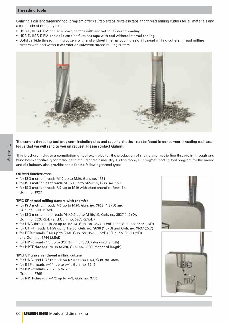
66 Mould and die making
Th
readin
g
Threading tools
Guhring‘s current threading tool program offers suitable taps, fluteless taps and thread milling cutters for all materials and a multitude of thread types:
• HSS-E, HSS-E PM and solid carbide taps with and without internal cooling• HSS-E, HSS-E PM and solid carbide fluteless taps with and without internal cooling• Solid carbide thread milling cutters with and without internal cooling as drill thread milling cutters, thread milling
cutters with and without chamfer or universal thread milling cutters
The current threading tool program - including dies and tapping chucks - can be found in our current threading tool cata-logue that we will send to you on request. Please contact Guhring!
This brochure includes a compilation of tool examples for the production of metric and metric fine threads in through and blind holes specifically for tasks in the mould and die industry. Furthermore, Guhring‘s threading tool program for the mould and die industry also provides tools for the following thread types:
Oil feed fluteless taps• for ISO metric threads M12 up to M20, Guh. no. 1931 • for ISO metric fine threads M10x1 up to M24x1.5, Guh. no. 1581• for ISO metric threads M3 up to M10 with short chamfer (form E),
Guh. no. 1927
TMC SP thread milling cutters with chamfer • for ISO metric threads M3 up to M20, Guh. no. 3525 (1,5xD) and
Guh. no. 3560 (2.5xD)• for ISO metric fine threads M4x0.5 up to M16x1.5, Guh. no. 3527 (1.5xD),
Guh. no. 3528 (2xD) and Guh. no. 3763 (2.5xD)• for UNC-threads 1/4-20 up to 1/2-13, Guh. no. 3524 (1.5xD) and Guh. no. 3535 (2xD)• for UNF-threads 1/4-28 up to 1/2-20, Guh. no. 3536 (1.5xD) and Guh. no. 3537 (2xD)• for BSP-threads G1/8 up to G3/8, Guh. no. 3529 (1.5xD), Guh. no. 3533 (2xD)
and Guh. no. 3766 (2.5xD)• for NPT-threads 1/8 up to 3/8, Guh. no. 3538 (standard length)• for NPTF-threads 1/8 up to 3/8, Guh. no. 3539 (standard length)
TMU SP universal thread milling cutters• for UNC- and UNF-threads >=1/2 up to >=1 1/4, Guh. no. 3596• for BSP-threads >=1/4 up to >=1, Guh. no. 3542• for NPT-threads >=1/2 up to >=1,
Guh. no. 3769• for NPTF-threads >=1/2 up to >=1, Guh. no. 3772
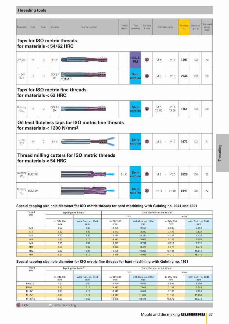
67Mould and die making
Th
read
ing
Threading tools
TiCN external cooling
Standard Type Form Tolerance Tool description Thread depth
Tool material
Surface finish Diameter range Guhring
no.Discount
group
Standard rangepage
Taps for ISO metric threads for materials < 54/62 HRC
DIN 371 H D 6HXHSS-E-
PMM 6 - M12 1201 103 70
~ DIN 371 H D ISO 2 /
6HSolid
carbideM 3 - M16 2944 103 68
Taps for ISO metric fine threads for materials < 62 HRC
Guhring std. H D ISO 2 /
6HSolid
carbideM 6
X0.50 - M12 X1.50 1161 103 69
Oil feed fluteless taps for ISO metric fine threads for materials < 1200 N/mm2
~ DIN 371 N C 6HX
Solid carbide
M 3 - M10 1972 103 71
Thread milling cutters for ISO metric threads for materials < 54 HRC
Guhring std. TMC SP 2 x D
Solid carbide
M 3 - M20 3526 108 72
Guhring std. TMU SP
Solid carbide
>=14 - >=30 3541 108 73
Thread size
Tapping size hole Ø Core diameter of int. thread
min. max.
to DIN 336 mm
with Guh. no. 2944 mm
to DIN 336 mm
with Guh. no. 2944 mm
to DIN 336 mm
with Guh. no. 2944 mm
M3 2.50 2.60 2.495 2.559 2.599 2.699
M4 3.30 3.40 3.242 3.342 3.422 3.522
M5 4.20 4.30 4.134 4.234 4.334 4.434
M6 5.00 5.10 4.917 5.017 5.153 5.253
M8 6.80 6.90 6.647 6.747 6.912 7.012
M10 8.50 8.60 8.376 8.476 8.676 8.776
M12 10.20 10.40 10.106 10.206 10.441 10.541
M16 12.00 14.10 13.835 15.935 14.210 16.310
Thread size
Tapping size hole Ø Core diameter of int. thread
min. max.
to DIN 336 mm
with Guh. no. 2944 mm
to DIN 336 mm
with Guh. no. 2944 mm
to DIN 336 mm
with Guh. no. 2944 mm
M6x0.5 5.50 5.60 5.459 5.559 5.599 5.699
M8x1 7.00 7.10 6.917 7.017 7.153 7.253
M10x1 9.00 9.10 8.917 9.017 9.153 9.253
M12x1 11.00 11.10 10.917 11.017 11.153 11.253
M12x1.5 10.50 10.60 10.376 10.476 10.676 10.776
Special tapping size hole diameter for ISO metric threads for hard machining with Guhring no. 2944 and 1201
Special tapping size hole diameter for ISO metric fine threads for hard machining with Guhring no. 1161
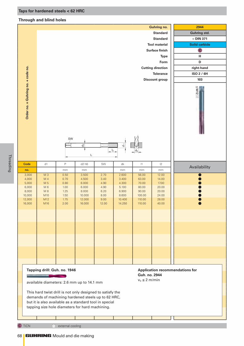
68
d1
l 1
SW
d 2
l2 dk
Mould and die making
Th
readin
g
Ord
er n
o. =
Gu
hri
ng
no.
+ c
od
e n
o.Guhring no. 2944
Standard Guhring std.
Standard ~ DIN 371
Tool material Solid carbide
Surface finish
Type H
Form D
Cutting direction right-hand
Tolerance ISO 2 / 6H
Discount group 103
Code d1 P d2 h6 SW dk l1 l2Availability
no. mm mm mm mm mm
3,000 M 3 0.50 3.500 2.70 2.600 56.00 12.004,000 M 4 0.70 4.500 3.40 3.400 63.00 14.005,000 M 5 0.80 6.000 4.90 4.300 70.00 17.006,000 M 6 1.00 6.000 4.90 5.100 80.00 20.008,000 M 8 1.25 8.000 6.20 6.900 90.00 20.00
10,000 M10 1.50 10.000 8.00 8.600 100.00 24.0012,000 M12 1.75 12.000 9.00 10.400 110.00 28.0016,000 M16 2.00 16.000 12.00 14.250 110.00 40.00
Taps for hardened steels < 62 HRC
TiCN external cooling
Through and blind holes
Tapping drill: Guh. no. 1946
available diameters: 2.6 mm up to 14.1 mm
This hard twist drill is not only designed to satisfy the demands of machining hardened steels up to 62 HRC, but it is also available as a standard tool in special tapping size hole diameters for hard machining.
Application recommendations for Guh. no. 2944vc ≤ 2 m/min
llllllll
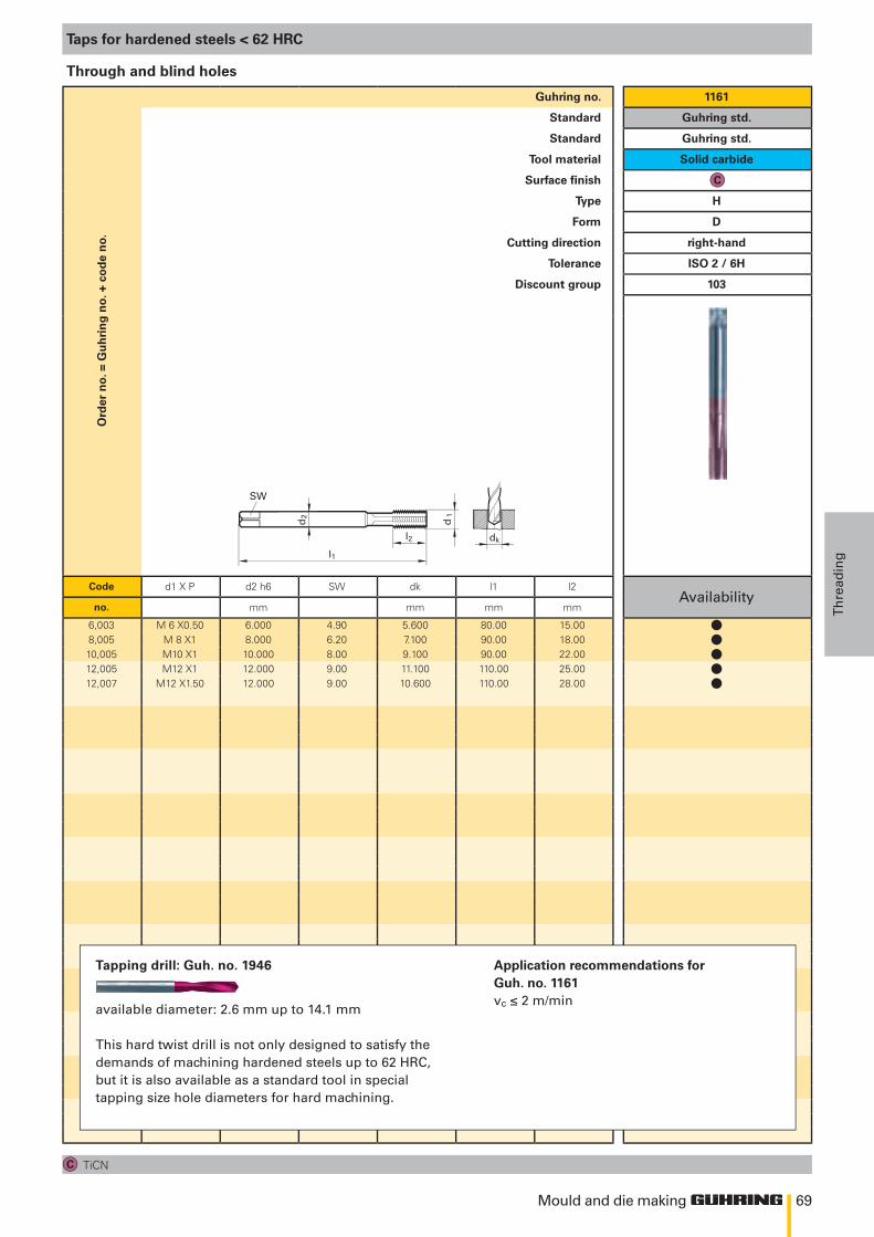
69
d1
l 1
SW
d 2
l2 dk
Mould and die making
Th
read
ing
Ord
er n
o. =
Gu
hri
ng
no.
+ c
od
e n
o.Guhring no. 1161
Standard Guhring std.
Standard Guhring std.
Tool material Solid carbide
Surface finish
Type H
Form D
Cutting direction right-hand
Tolerance ISO 2 / 6H
Discount group 103
Code d1 X P d2 h6 SW dk l1 l2Availability
no. mm mm mm mm
6,003 M 6 X0.50 6.000 4.90 5.600 80.00 15.008,005 M 8 X1 8.000 6.20 7.100 90.00 18.0010,005 M10 X1 10.000 8.00 9.100 90.00 22.0012,005 M12 X1 12.000 9.00 11.100 110.00 25.0012,007 M12 X1.50 12.000 9.00 10.600 110.00 28.00
Taps for hardened steels < 62 HRC
TiCN
Through and blind holes
Tapping drill: Guh. no. 1946
available diameter: 2.6 mm up to 14.1 mm
This hard twist drill is not only designed to satisfy the demands of machining hardened steels up to 62 HRC, but it is also available as a standard tool in special tapping size hole diameters for hard machining.
Application recommendations for Guh. no. 1161vc ≤ 2 m/min
lllll
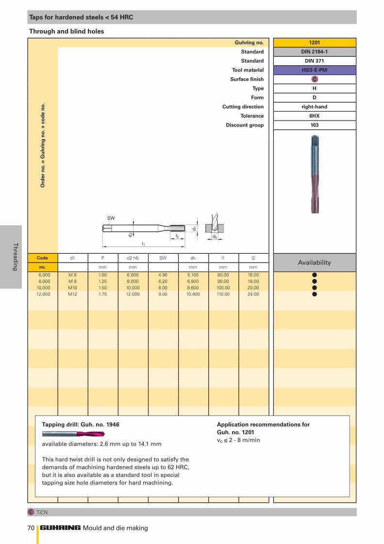
70
d 1
l 1
SW
d2
l 2 dk
Mould and die making
Th
readin
g
Ord
er n
o. =
Gu
hri
ng
no.
+ c
od
e n
o.Guhring no. 1201
Standard DIN 2184-1
Standard DIN 371
Tool material HSS-E-PM
Surface finish
Type H
Form D
Cutting direction right-hand
Tolerance 6HX
Discount group 103
Code d1 P d2 h6 SW dk l1 l2Availability
no. mm mm mm mm mm
6,000 M 6 1.00 6.000 4.90 5.100 80.00 16.008,000 M 8 1.25 8.000 6.20 6.900 90.00 18.00
10,000 M10 1.50 10.000 8.00 8.600 100.00 20.0012,000 M12 1.75 12.000 9.00 10.400 110.00 24.00
Taps for hardened steels < 54 HRC
TiCN
Through and blind holes
Tapping drill: Guh. no. 1946
available diameters: 2.6 mm up to 14.1 mm
This hard twist drill is not only designed to satisfy the demands of machining hardened steels up to 62 HRC, but it is also available as a standard tool in special tapping size hole diameters for hard machining.
Application recommendations for Guh. no. 1201vc ≤ 2 - 8 m/min
llll
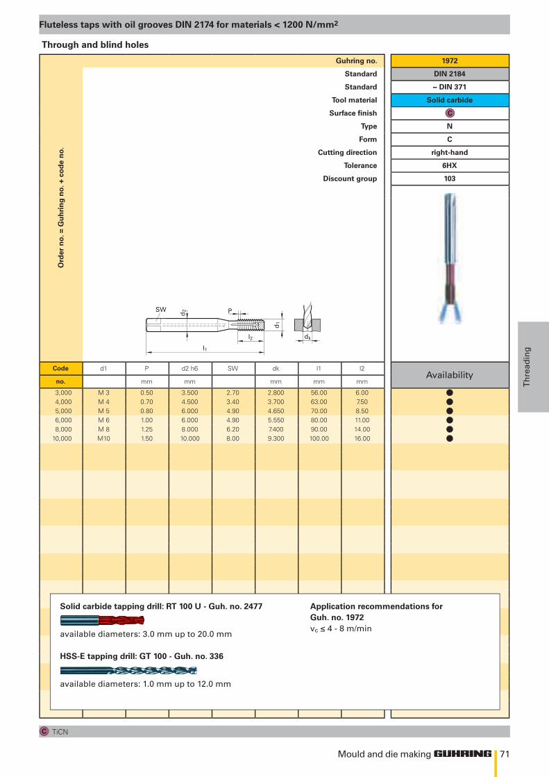
71
d k
d 1
l 1
SW
d 2
l 2
P
Mould and die making
Th
read
ing
Ord
er n
o. =
Gu
hri
ng
no.
+ c
od
e n
o.Guhring no. 1972
Standard DIN 2184
Standard ~ DIN 371
Tool material Solid carbide
Surface finish
Type N
Form C
Cutting direction right-hand
Tolerance 6HX
Discount group 103
Code d1 P d2 h6 SW dk l1 l2Availability
no. mm mm mm mm mm
3,000 M 3 0.50 3.500 2.70 2.800 56.00 6.004,000 M 4 0.70 4.500 3.40 3.700 63.00 7.505,000 M 5 0.80 6.000 4.90 4.650 70.00 8.506,000 M 6 1.00 6.000 4.90 5.550 80.00 11.008,000 M 8 1.25 8.000 6.20 7.400 90.00 14.00
10,000 M10 1.50 10.000 8.00 9.300 100.00 16.00
Fluteless taps with oil grooves DIN 2174 for materials < 1200 N/mm2
TiCN
Through and blind holes
Solid carbide tapping drill: RT 100 U - Guh. no. 2477
available diameters: 3.0 mm up to 20.0 mm
HSS-E tapping drill: GT 100 - Guh. no. 336
available diameters: 1.0 mm up to 12.0 mm
Application recommendations for Guh. no. 1972vc ≤ 4 - 8 m/min
llllll
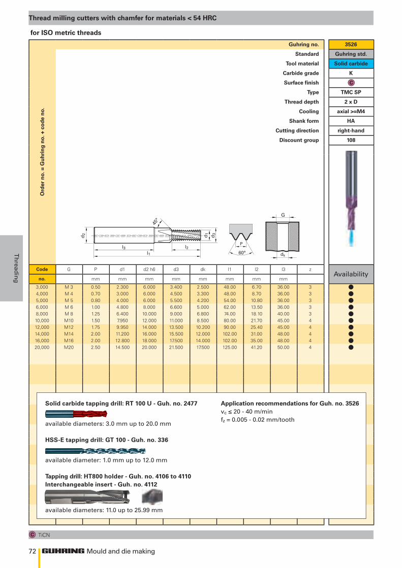
72
60°
P
G
dk
45°
l3 l2l1
d2 d1
d3
Mould and die making
Th
readin
g
Ord
er n
o. =
Gu
hri
ng
no.
+ c
od
e n
o.Guhring no. 3526
Standard Guhring std.
Tool material Solid carbide
Carbide grade K
Surface finish
Type TMC SP
Thread depth 2 x D
Cooling axial >=M4
Shank form HA
Cutting direction right-hand
Discount group 108
Code G P d1 d2 h6 d3 dk l1 l2 l3 zAvailability
no. mm mm mm mm mm mm mm mm
3,000 M 3 0.50 2.300 6.000 3.400 2.500 48.00 6.70 36.00 34,000 M 4 0.70 3.000 6.000 4.500 3.300 48.00 8.70 36.00 35,000 M 5 0.80 4.000 6.000 5.500 4.200 54.00 10.80 36.00 36,000 M 6 1.00 4.800 8.000 6.600 5.000 62.00 13.50 36.00 38,000 M 8 1.25 6.400 10.000 9.000 6.800 74.00 18.10 40.00 310,000 M10 1.50 7.950 12.000 11.000 8.500 80.00 21.70 45.00 412,000 M12 1.75 9.950 14.000 13.500 10.200 90.00 25.40 45.00 414,000 M14 2.00 11.200 16.000 15.500 12.000 102.00 31.00 48.00 416,000 M16 2.00 12.800 18.000 17.500 14.000 102.00 35.00 48.00 420,000 M20 2.50 14.500 20.000 21.500 17.500 125.00 41.20 50.00 4
Thread milling cutters with chamfer for materials < 54 HRC
TiCN
for ISO metric threads
Solid carbide tapping drill: RT 100 U - Guh. no. 2477
available diameters: 3.0 mm up to 20.0 mm
HSS-E tapping drill: GT 100 - Guh. no. 336
available diameter: 1.0 mm up to 12.0 mm
Tapping drill: HT800 holder - Guh. no. 4106 to 4110Interchangeable insert - Guh. no. 4112
available diameters: 11.0 up to 25.99 mm
Application recommendations for Guh. no. 3526vc ≤ 20 - 40 m/minfz = 0.005 - 0.02 mm/tooth
llllllllll
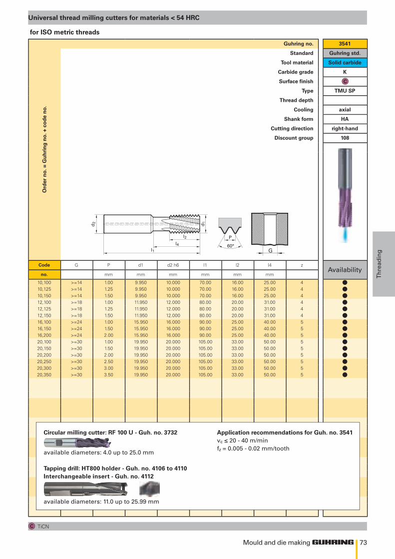
73
G60°
Pl2
l1
d2 d1
l4
Mould and die making
Th
read
ing
Ord
er n
o. =
Gu
hri
ng
no.
+ c
od
e n
o.Guhring no. 3541
Standard Guhring std.
Tool material Solid carbide
Carbide grade K
Surface finish
Type TMU SP
Thread depth
Cooling axial
Shank form HA
Cutting direction right-hand
Discount group 108
Code G P d1 d2 h6 l1 l2 l4 zAvailability
no. mm mm mm mm mm mm
10,100 >=14 1.00 9.950 10.000 70.00 16.00 25.00 410,125 >=14 1.25 9.950 10.000 70.00 16.00 25.00 410,150 >=14 1.50 9.950 10.000 70.00 16.00 25.00 412,100 >=18 1.00 11.950 12.000 80.00 20.00 31.00 412,125 >=18 1.25 11.950 12.000 80.00 20.00 31.00 412,150 >=18 1.50 11.950 12.000 80.00 20.00 31.00 416,100 >=24 1.00 15.950 16.000 90.00 25.00 40.00 516,150 >=24 1.50 15.950 16.000 90.00 25.00 40.00 516,200 >=24 2.00 15.950 16.000 90.00 25.00 40.00 520,100 >=30 1.00 19.950 20.000 105.00 33.00 50.00 520,150 >=30 1.50 19.950 20.000 105.00 33.00 50.00 520,200 >=30 2.00 19.950 20.000 105.00 33.00 50.00 520,250 >=30 2.50 19.950 20.000 105.00 33.00 50.00 520,300 >=30 3.00 19.950 20.000 105.00 33.00 50.00 520,350 >=30 3.50 19.950 20.000 105.00 33.00 50.00 5
Universal thread milling cutters for materials < 54 HRC
TiCN
for ISO metric threads
Application recommendations for Guh. no. 3541vc ≤ 20 - 40 m/minfz = 0.005 - 0.02 mm/tooth
Circular milling cutter: RF 100 U - Guh. no. 3732
available diameters: 4.0 up to 25.0 mm
Tapping drill: HT800 holder - Guh. no. 4106 to 4110Interchangeable insert - Guh. no. 4112
available diameters: 11.0 up to 25.99 mm
lllllllllllllll
Mould and die MakingreaminG

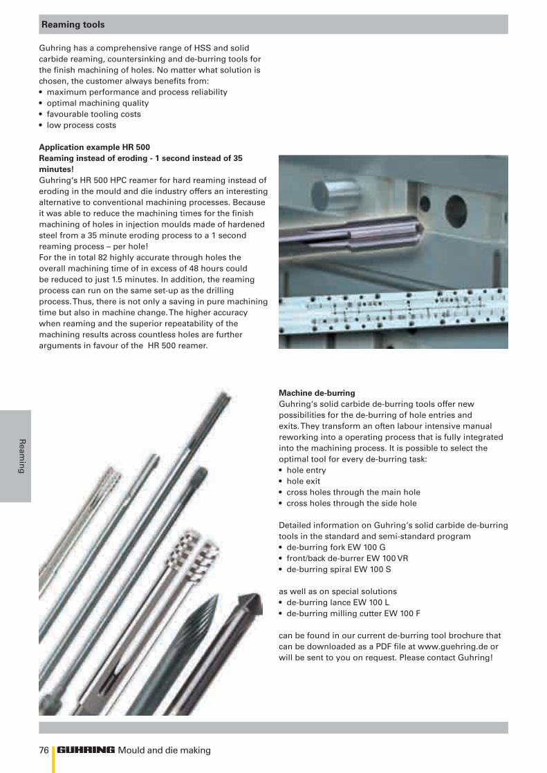
76 Mould and die making
Ream
ing
Reaming tools
Guhring has a comprehensive range of HSS and solid carbide reaming, countersinking and de-burring tools for the finish machining of holes. No matter what solution is chosen, the customer always benefits from:• maximum performance and process reliability• optimal machining quality• favourable tooling costs• low process costs
Application example HR 500Reaming instead of eroding - 1 second instead of 35 minutes!Guhring‘s HR 500 HPC reamer for hard reaming instead of eroding in the mould and die industry offers an interesting alternative to conventional machining processes. Because it was able to reduce the machining times for the finish machining of holes in injection moulds made of hardened steel from a 35 minute eroding process to a 1 second reaming process – per hole! For the in total 82 highly accurate through holes the overall machining time of in excess of 48 hours could be reduced to just 1.5 minutes. In addition, the reaming process can run on the same set-up as the drilling process. Thus, there is not only a saving in pure machining time but also in machine change. The higher accuracy when reaming and the superior repeatability of the machining results across countless holes are further arguments in favour of the HR 500 reamer.
Machine de-burringGuhring‘s solid carbide de-burring tools offer new possibilities for the de-burring of hole entries and exits. They transform an often labour intensive manual reworking into a operating process that is fully integrated into the machining process. It is possible to select the optimal tool for every de-burring task:• hole entry• hole exit• cross holes through the main hole• cross holes through the side hole
Detailed information on Guhring‘s solid carbide de-burring tools in the standard and semi-standard program• de-burring fork EW 100 G• front/back de-burrer EW 100 VR• de-burring spiral EW 100 S
as well as on special solutions• de-burring lance EW 100 L• de-burring milling cutter EW 100 F
can be found in our current de-burring tool brochure that can be downloaded as a PDF file at www.guehring.de or will be sent to you on request. Please contact Guhring!
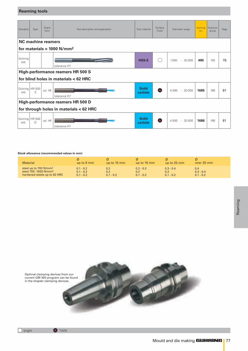
77Mould and die making
Rea
min
g
Reaming tools
bright TiAlN
Standard Type Shank form Tool description and application Tool material Surface
finish Diameter range Guhring no.
Discount group Page
NC machine reamers
for materials < 1000 N/mm2
Guhring std.
tolerance H7
HSS-E 1.500 - 20.000 490 105 78
High-performance reamers HR 500 S
for blind holes in materials < 62 HRC
Guhring std.
HR 500 S zyl. h6
tolerance H7
Solid carbide
4.000 - 20.000 1685 166 81
High-performance reamers HR 500 D
for through holes in materials < 62 HRC
Guhring std.
HR 500 D zyl. h6
tolerance H7
Solid carbide
4.000 - 20.000 1686 166 81
Optimal clamping devices from our current GM 300 program can be found in the chapter clamping devices.
Material Ø up to 6 mm
Ø up to 10 mm
Ø up to 16 mm
Ø up to 25 mm
Ø over 25 mm
steel up to 700 N/mm2 steel 700 -1000 N/mm2
hardened steels up to 62 HRC
0.1 - 0.2 0.2 0.2 - 0.3 0.3 - 0.4 0.4 0.1 - 0.2 0.2 0.2 0.3 0.3 - 0.4 0.1 - 0.2 0.1 - 0.2 0.1 - 0.2 0.1 - 0.2 0.1 - 0.2
Stock allowance (recommended values in mm)
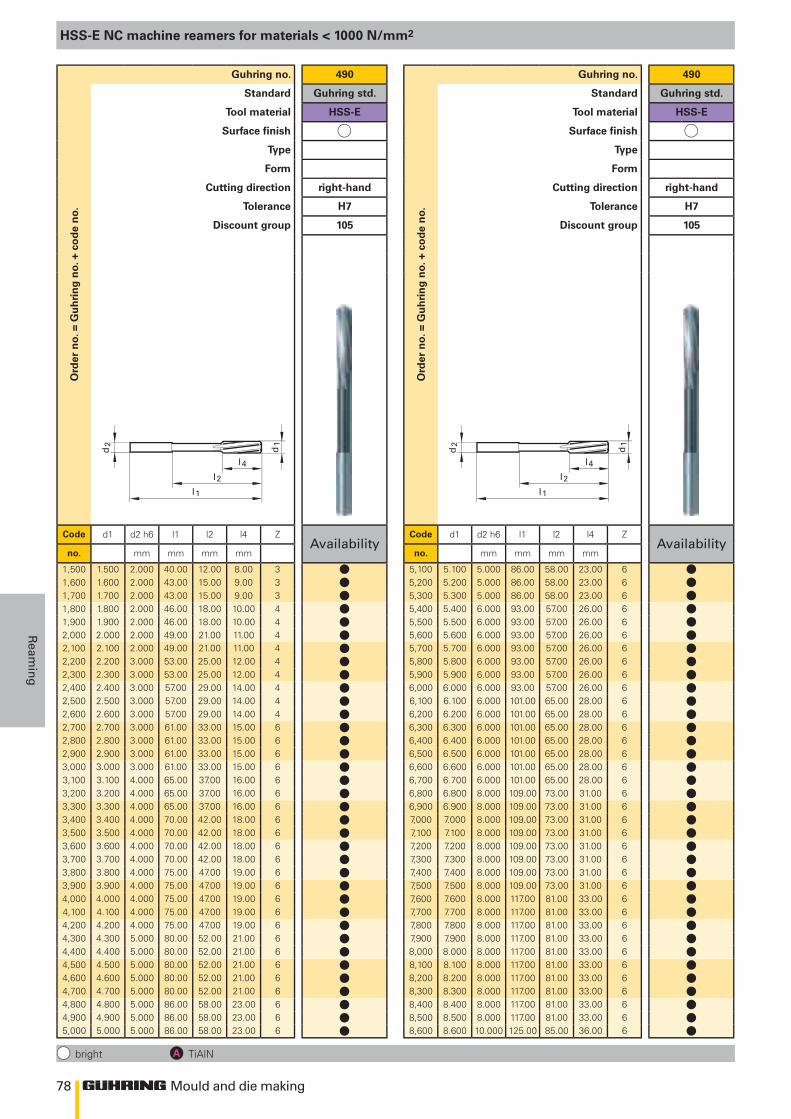
78
d2
l 1
d1
l 4
l2
d2
l 1
d1
l 4
l2
Mould and die making
Ream
ing
HSS-E NC machine reamers for materials < 1000 N/mm2
bright TiAlN
Ord
er n
o. =
Gu
hri
ng
no.
+ c
od
e n
o.Guhring no. 490
Standard Guhring std.
Tool material HSS-E
Surface finish
Type
Form
Cutting direction right-hand
Tolerance H7
Discount group 105
Code d1 d2 h6 l1 l2 l4 ZAvailability
no. mm mm mm mm
1,500 1.500 2.000 40.00 12.00 8.00 31,600 1.600 2.000 43.00 15.00 9.00 31,700 1.700 2.000 43.00 15.00 9.00 31,800 1.800 2.000 46.00 18.00 10.00 41,900 1.900 2.000 46.00 18.00 10.00 42,000 2.000 2.000 49.00 21.00 11.00 42,100 2.100 2.000 49.00 21.00 11.00 42,200 2.200 3.000 53.00 25.00 12.00 42,300 2.300 3.000 53.00 25.00 12.00 42,400 2.400 3.000 57.00 29.00 14.00 42,500 2.500 3.000 57.00 29.00 14.00 42,600 2.600 3.000 57.00 29.00 14.00 42,700 2.700 3.000 61.00 33.00 15.00 62,800 2.800 3.000 61.00 33.00 15.00 62,900 2.900 3.000 61.00 33.00 15.00 63,000 3.000 3.000 61.00 33.00 15.00 63,100 3.100 4.000 65.00 37.00 16.00 63,200 3.200 4.000 65.00 37.00 16.00 63,300 3.300 4.000 65.00 37.00 16.00 63,400 3.400 4.000 70.00 42.00 18.00 63,500 3.500 4.000 70.00 42.00 18.00 63,600 3.600 4.000 70.00 42.00 18.00 63,700 3.700 4.000 70.00 42.00 18.00 63,800 3.800 4.000 75.00 47.00 19.00 63,900 3.900 4.000 75.00 47.00 19.00 64,000 4.000 4.000 75.00 47.00 19.00 64,100 4.100 4.000 75.00 47.00 19.00 64,200 4.200 4.000 75.00 47.00 19.00 64,300 4.300 5.000 80.00 52.00 21.00 64,400 4.400 5.000 80.00 52.00 21.00 64,500 4.500 5.000 80.00 52.00 21.00 64,600 4.600 5.000 80.00 52.00 21.00 64,700 4.700 5.000 80.00 52.00 21.00 64,800 4.800 5.000 86.00 58.00 23.00 64,900 4.900 5.000 86.00 58.00 23.00 65,000 5.000 5.000 86.00 58.00 23.00 6
Ord
er n
o. =
Gu
hri
ng
no.
+ c
od
e n
o.
Guhring no. 490
Standard Guhring std.
Tool material HSS-E
Surface finish
Type
Form
Cutting direction right-hand
Tolerance H7
Discount group 105
Code d1 d2 h6 l1 l2 l4 ZAvailability
no. mm mm mm mm
5,100 5.100 5.000 86.00 58.00 23.00 65,200 5.200 5.000 86.00 58.00 23.00 65,300 5.300 5.000 86.00 58.00 23.00 65,400 5.400 6.000 93.00 57.00 26.00 65,500 5.500 6.000 93.00 57.00 26.00 65,600 5.600 6.000 93.00 57.00 26.00 65,700 5.700 6.000 93.00 57.00 26.00 65,800 5.800 6.000 93.00 57.00 26.00 65,900 5.900 6.000 93.00 57.00 26.00 66,000 6.000 6.000 93.00 57.00 26.00 66,100 6.100 6.000 101.00 65.00 28.00 66,200 6.200 6.000 101.00 65.00 28.00 66,300 6.300 6.000 101.00 65.00 28.00 66,400 6.400 6.000 101.00 65.00 28.00 66,500 6.500 6.000 101.00 65.00 28.00 66,600 6.600 6.000 101.00 65.00 28.00 66,700 6.700 6.000 101.00 65.00 28.00 66,800 6.800 8.000 109.00 73.00 31.00 66,900 6.900 8.000 109.00 73.00 31.00 67,000 7.000 8.000 109.00 73.00 31.00 67,100 7.100 8.000 109.00 73.00 31.00 67,200 7.200 8.000 109.00 73.00 31.00 67,300 7.300 8.000 109.00 73.00 31.00 67,400 7.400 8.000 109.00 73.00 31.00 67,500 7.500 8.000 109.00 73.00 31.00 67,600 7.600 8.000 117.00 81.00 33.00 67,700 7.700 8.000 117.00 81.00 33.00 67,800 7.800 8.000 117.00 81.00 33.00 67,900 7.900 8.000 117.00 81.00 33.00 68,000 8.000 8.000 117.00 81.00 33.00 68,100 8.100 8.000 117.00 81.00 33.00 68,200 8.200 8.000 117.00 81.00 33.00 68,300 8.300 8.000 117.00 81.00 33.00 68,400 8.400 8.000 117.00 81.00 33.00 68,500 8.500 8.000 117.00 81.00 33.00 68,600 8.600 10.000 125.00 85.00 36.00 6
llllllllllllllllllllllllllllllllllll
llllllllllllllllllllllllllllllllllll
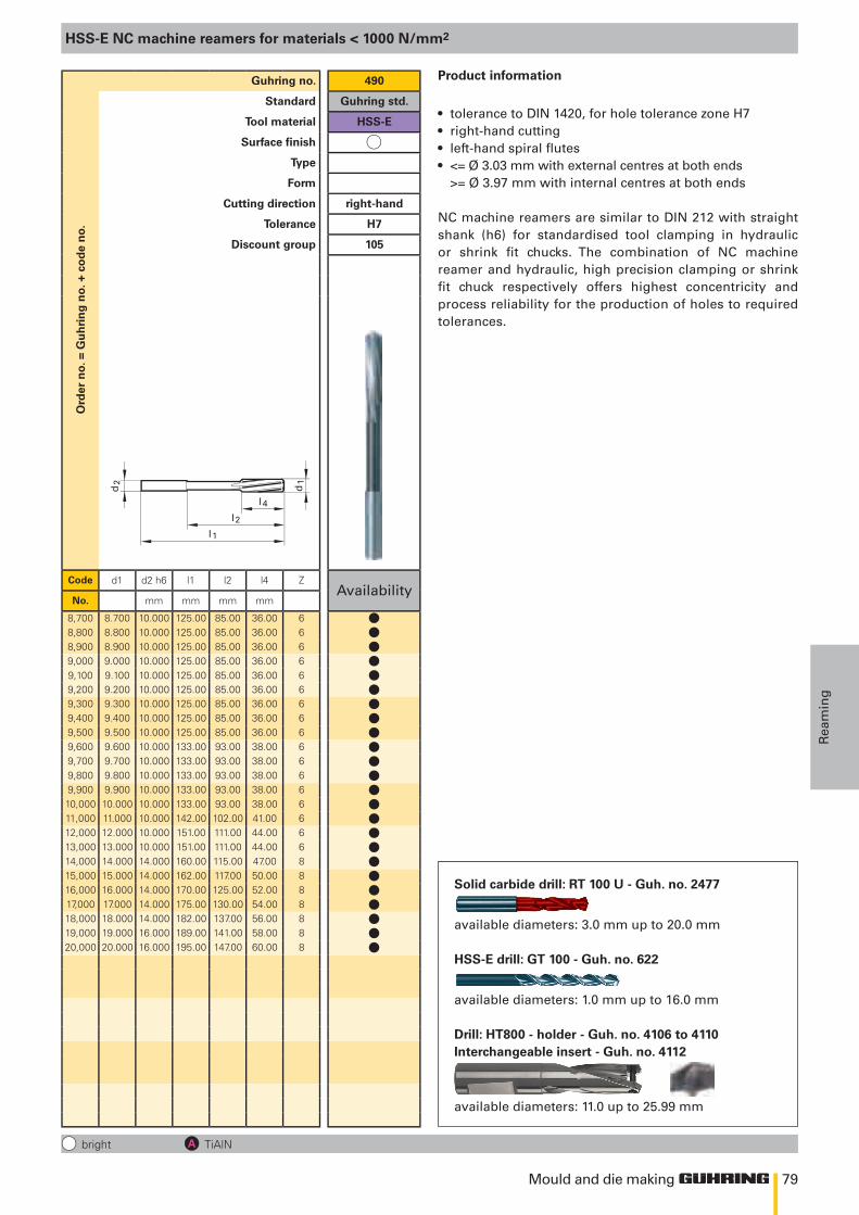
79
d2
l 1
d1
l 4
l2
Mould and die making
Rea
min
g
HSS-E NC machine reamers for materials < 1000 N/mm2
bright TiAlN
Ord
er n
o. =
Gu
hri
ng
no.
+ c
od
e n
o.Guhring no. 490
Standard Guhring std.
Tool material HSS-E
Surface finish
Type
Form
Cutting direction right-hand
Tolerance H7
Discount group 105
Code d1 d2 h6 l1 l2 l4 ZAvailability
No. mm mm mm mm
8,700 8.700 10.000 125.00 85.00 36.00 68,800 8.800 10.000 125.00 85.00 36.00 68,900 8.900 10.000 125.00 85.00 36.00 69,000 9.000 10.000 125.00 85.00 36.00 69,100 9.100 10.000 125.00 85.00 36.00 69,200 9.200 10.000 125.00 85.00 36.00 69,300 9.300 10.000 125.00 85.00 36.00 69,400 9.400 10.000 125.00 85.00 36.00 69,500 9.500 10.000 125.00 85.00 36.00 69,600 9.600 10.000 133.00 93.00 38.00 69,700 9.700 10.000 133.00 93.00 38.00 69,800 9.800 10.000 133.00 93.00 38.00 69,900 9.900 10.000 133.00 93.00 38.00 610,000 10.000 10.000 133.00 93.00 38.00 611,000 11.000 10.000 142.00 102.00 41.00 612,000 12.000 10.000 151.00 111.00 44.00 613,000 13.000 10.000 151.00 111.00 44.00 614,000 14.000 14.000 160.00 115.00 47.00 815,000 15.000 14.000 162.00 117.00 50.00 816,000 16.000 14.000 170.00 125.00 52.00 817,000 17.000 14.000 175.00 130.00 54.00 818,000 18.000 14.000 182.00 137.00 56.00 819,000 19.000 16.000 189.00 141.00 58.00 820,000 20.000 16.000 195.00 147.00 60.00 8
Solid carbide drill: RT 100 U - Guh. no. 2477
available diameters: 3.0 mm up to 20.0 mm
HSS-E drill: GT 100 - Guh. no. 622
available diameters: 1.0 mm up to 16.0 mm
Drill: HT800 - holder - Guh. no. 4106 to 4110Interchangeable insert - Guh. no. 4112
available diameters: 11.0 up to 25.99 mm
Product information
• tolerance to DIN 1420, for hole tolerance zone H7• right-hand cutting• left-hand spiral flutes• <= Ø 3.03 mm with external centres at both ends
>= Ø 3.97 mm with internal centres at both ends
NC machine reamers are similar to DIN 212 with straight shank (h6) for standardised tool clamping in hydraulic or shrink fit chucks. The combination of NC machine reamer and hydraulic, high precision clamping or shrink fit chuck respectively offers highest concentricity and process reliability for the production of holes to required tolerances.
llllllllllllllllllllllll
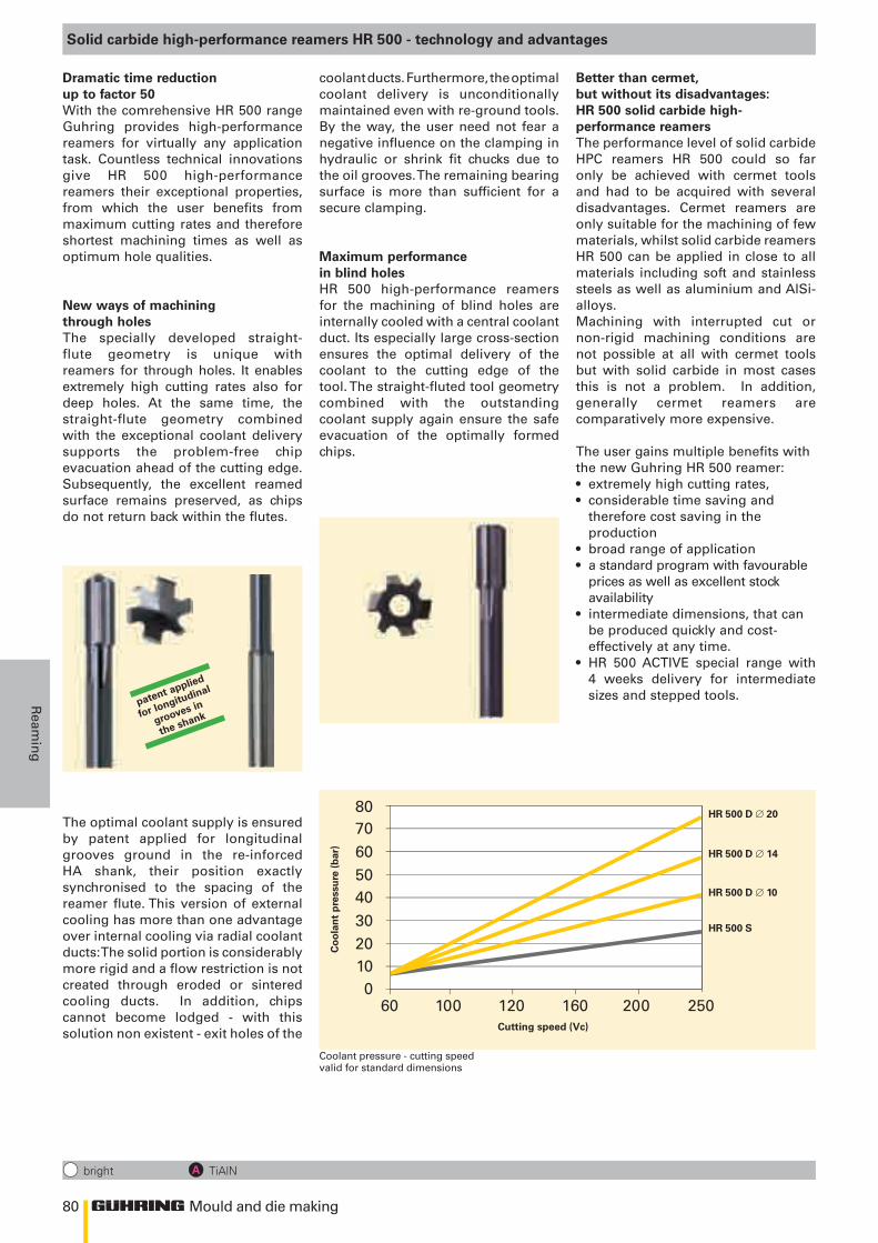
80
0102030405060
60 100 120 160 200 250
7080
Mould and die making
Ream
ing
bright TiAlN
Solid carbide high-performance reamers HR 500 - technology and advantages
Dramatic time reduction up to factor 50With the comrehensive HR 500 range Guhring provides high-performance reamers for virtually any application task. Countless technical innovations give HR 500 high-performance reamers their exceptional properties, from which the user benefits from maximum cutting rates and therefore shortest machining times as well as optimum hole qualities.
New ways of machining through holesThe specially developed straight-flute geometry is unique with reamers for through holes. It enables extremely high cutting rates also for deep holes. At the same time, the straight-flute geometry combined with the exceptional coolant delivery supports the problem-free chip evacuation ahead of the cutting edge. Subsequently, the excellent reamed surface remains preserved, as chips do not return back within the flutes.
Coolant pressure - cutting speedvalid for standard dimensions
Cutting speed (Vc)
HR 500 D ∅ 20
HR 500 D ∅ 14
HR 500 D ∅ 10
HR 500 S
Co
ola
nt
pre
ssu
re (b
ar)
patent applied
for longitudinal
grooves in
the shank
The optimal coolant supply is ensured by patent applied for longitudinal grooves ground in the re-inforced HA shank, their position exactly synchronised to the spacing of the reamer flute. This version of external cooling has more than one advantage over internal cooling via radial coolant ducts: The solid portion is considerably more rigid and a flow restriction is not created through eroded or sintered cooling ducts. In addition, chips cannot become lodged - with this solution non existent - exit holes of the
coolant ducts. Furthermore, the optimal coolant delivery is unconditionally maintained even with re-ground tools. By the way, the user need not fear a negative influence on the clamping in hydraulic or shrink fit chucks due to the oil grooves. The remaining bearing surface is more than sufficient for a secure clamping.
Maximum performance in blind holesHR 500 high-performance reamers for the machining of blind holes are internally cooled with a central coolant duct. Its especially large cross-section ensures the optimal delivery of the coolant to the cutting edge of the tool. The straight-fluted tool geometry combined with the outstanding coolant supply again ensure the safe evacuation of the optimally formed chips.
Better than cermet, but without its disadvantages: HR 500 solid carbide high-performance reamersThe performance level of solid carbide HPC reamers HR 500 could so far only be achieved with cermet tools and had to be acquired with several disadvantages. Cermet reamers are only suitable for the machining of few materials, whilst solid carbide reamers HR 500 can be applied in close to all materials including soft and stainless steels as well as aluminium and AlSi-alloys. Machining with interrupted cut or non-rigid machining conditions are not possible at all with cermet tools but with solid carbide in most cases this is not a problem. In addition, generally cermet reamers are comparatively more expensive.
The user gains multiple benefits with the new Guhring HR 500 reamer:• extremely high cutting rates,• considerable time saving and therefore cost saving in the production• broad range of application• a standard program with favourable
prices as well as excellent stock availability
• intermediate dimensions, that can be produced quickly and cost- effectively at any time.
• HR 500 ACTIVE special range with 4 weeks delivery for intermediate sizes and stepped tools.
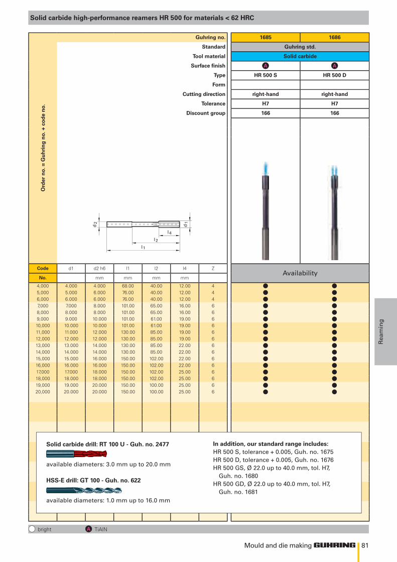
81
d2
l 1
d1
l 4
l2
Mould and die making
Rea
min
g
bright TiAlN
Solid carbide high-performance reamers HR 500 for materials < 62 HRC
Ord
er n
o. =
Gu
hri
ng
no.
+ c
od
e n
o.Guhring no. 1685 1686
Standard Guhring std.
Tool material Solid carbide
Surface finish
Type HR 500 S HR 500 D
Form
Cutting direction right-hand right-hand
Tolerance H7 H7
Discount group 166 166
Code d1 d2 h6 l1 l2 l4 ZAvailability
No. mm mm mm mm
4,000 4.000 4.000 68.00 40.00 12.00 45,000 5.000 6.000 76.00 40.00 12.00 46,000 6.000 6.000 76.00 40.00 12.00 47,000 7.000 8.000 101.00 65.00 16.00 68,000 8.000 8.000 101.00 65.00 16.00 69,000 9.000 10.000 101.00 61.00 19.00 610,000 10.000 10.000 101.00 61.00 19.00 611,000 11.000 12.000 130.00 85.00 19.00 612,000 12.000 12.000 130.00 85.00 19.00 613,000 13.000 14.000 130.00 85.00 22.00 614,000 14.000 14.000 130.00 85.00 22.00 615,000 15.000 16.000 150.00 102.00 22.00 616,000 16.000 16.000 150.00 102.00 22.00 617,000 17.000 18.000 150.00 102.00 25.00 618,000 18.000 18.000 150.00 102.00 25.00 619,000 19.000 20.000 150.00 100.00 25.00 620,000 20.000 20.000 150.00 100.00 25.00 6
In addition, our standard range includes:HR 500 S, tolerance + 0.005, Guh. no. 1675HR 500 D, tolerance + 0.005, Guh. no. 1676HR 500 GS, Ø 22.0 up to 40.0 mm, tol. H7,
Guh. no. 1680HR 500 GD, Ø 22.0 up to 40.0 mm, tol. H7,
Guh. no. 1681
Solid carbide drill: RT 100 U - Guh. no. 2477
available diameters: 3.0 mm up to 20.0 mm
HSS-E drill: GT 100 - Guh. no. 622
available diameters: 1.0 mm up to 16.0 mm
l ll ll ll ll ll ll ll ll ll ll ll ll ll ll ll ll l
Mould and die MakingclampinG devices
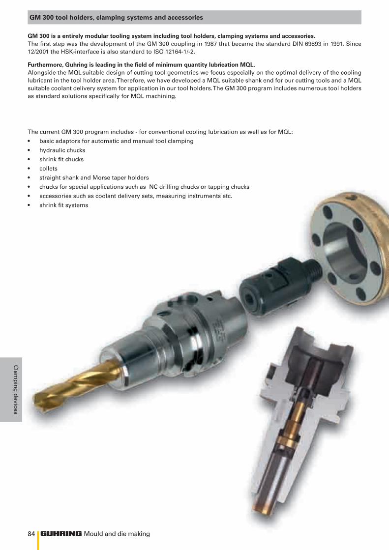
84 Mould and die making
Clam
pin
g d
evices
GM 300 tool holders, clamping systems and accessories
GM 300 is a entirely modular tooling system including tool holders, clamping systems and accessories.The first step was the development of the GM 300 coupling in 1987 that became the standard DIN 69893 in 1991. Since 12/2001 the HSK-interface is also standard to ISO 12164-1/-2.
The current GM 300 program includes - for conventional cooling lubrication as well as for MQL:
• basic adaptors for automatic and manual tool clamping
• hydraulic chucks
• shrink fit chucks
• collets
• straight shank and Morse taper holders
• chucks for special applications such as NC drilling chucks or tapping chucks
• accessories such as coolant delivery sets, measuring instruments etc.
• shrink fit systems
Furthermore, Guhring is leading in the field of minimum quantity lubrication MQL. Alongside the MQL-suitable design of cutting tool geometries we focus especially on the optimal delivery of the cooling lubricant in the tool holder area. Therefore, we have developed a MQL suitable shank end for our cutting tools and a MQL suitable coolant delivery system for application in our tool holders. The GM 300 program includes numerous tool holders as standard solutions specifically for MQL machining.
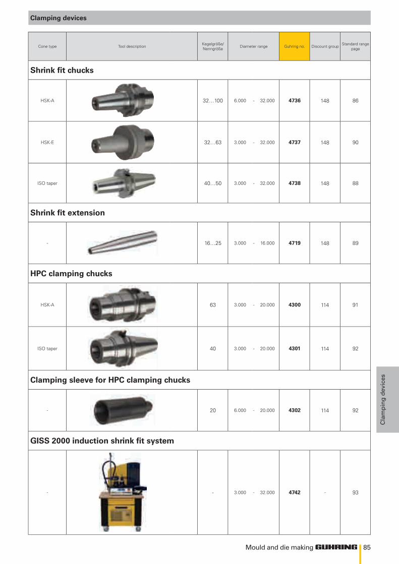
85
148
148
148
148
114
114
114
Mould and die making
Cla
mp
ing
dev
ices
Clamping devices
Cone type Tool description Kegelgröße/Nenngröße Diameter range Guhring no. Discount group Standard range
page
Shrink fit chucks
HSK-A 32…100 6.000 - 32.000 4736 86
HSK-E 32…63 3.000 - 32.000 4737 90
ISO taper 40…50 3.000 - 32.000 4738 88
Shrink fit extension
- 16…25 3.000 - 16.000 4719 89
HPC clamping chucks
HSK-A 63 3.000 - 20.000 4300 91
ISO taper 40 3.000 - 20.000 4301 92
Clamping sleeve for HPC clamping chucks
- 20 6.000 - 20.000 4302 92
GISS 2000 induction shrink fit system
- - 3.000 - 32.000 4742 - 93
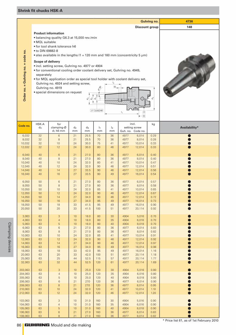
86
l2
10
l1
d1
d2
4o 30
´
d4
A0,003 AB
d3
B
Mould and die making
Clam
pin
g d
evices
Shrink fit chucks HSK-A
Guhring no. 4736
Discount group 148O
rder
no.
= G
uh
rin
g n
o. +
co
de
no.
Product information• balancing quality G6.3 at 15,000 rev./min• MQL suitable• for tool shank tolerance h6• to DIN 69882-8• also available in the lengths l1 = 120 mm and 160 mm (concentricity 5 μm)
Scope of delivery• incl. setting screw, Guhring no. 4977 or 4904• for conventional cooling order coolant delivery set, Guhring no. 4949,
separately• for MQL application order as special tool holder with coolant delivery set,
Guhring no. 4924 and setting screw,Guhring no. 4919
• special dimensions on request
Code no.HSK-A
d3 for
clamping-Ød1 h6 mm
d2mm
d4mm
l1mm
l2mm
incl.setting screw
Guh. no. Code no.
kg
6,032 32 6 21 25.5 70 36 4977 6,014 0.298,032 32 8 21 25.5 70 36 4977 8,014 0.28
10,032 32 10 24 30.0 75 41 4977 10,014 0.3312,032 32 12 24 30.0 80 46 4977 12,014 0.33
6,040 40 6 21 27.0 80 36 4977 6,014 0.408,040 40 8 21 27.0 80 36 4977 8,014 0.40
10,040 40 10 24 32.0 80 41 4977 10,014 0.4712,040 40 12 24 32.0 90 46 4977 12,014 0.5114,040 40 14 27 33.5 90 46 4977 12,014 0.5616,040 40 16 27 33.5 90 49 4977 16,014 0.54
6,050 50 6 21 27.0 80 36 4977 6,014 0.578,050 50 8 21 27.0 80 36 4977 8,014 0.58
10,050 50 10 24 32.0 85 41 4977 10,014 0.6512,050 50 12 24 32.0 90 46 4977 12,014 0.6714,050 50 14 27 34.0 90 46 4977 12,014 0.7216,050 50 16 27 34.0 95 49 4977 16,014 0.7318,050 50 18 33 41.5 95 49 4977 16,014 0.9020,050 50 20 33 41.5 100 51 4977 20,114 0.92
3,063 63 3 10 18.0 80 30 4904 5,016 0.704,063 63 4 10 18.0 80 35 4904 6,016 0.705,063 63 5 10 18.0 80 40 4904 8,018 0.706,063 63 6 21 27.0 80 36 4977 6,014 0.838,063 63 8 21 27.0 80 36 4977 8,014 0.82
10,063 63 10 24 32.0 85 41 4977 10,014 0.9112,063 63 12 24 32.0 90 46 4977 12,014 0.9214,063 63 14 27 34.0 90 46 4977 12,014 0.9716,063 63 16 27 34.0 95 49 4977 16,014 0.9818,063 63 18 33 42.0 95 49 4977 16,014 1.1620,063 63 20 33 42.0 100 51 4977 20,114 1.1825,063 63 25 44 52.5 115 57 4977 20,114 1.7732,063 63 32 44 52.5 120 61 4977 20,114 1.69
203,063 63 3 10 25.0 120 30 4904 5,016 0.80204,063 63 4 10 25.0 120 35 4904 6,016 0.80205,063 63 5 10 25.0 120 40 4904 8,018 0.80206,063 63 6 21 27.0 120 36 4977 6,014 0.90208,063 63 8 21 27.0 120 36 4977 8,014 0.95210,063 63 10 24 32.0 120 41 4977 10,014 1.10212,063 63 12 24 32.0 120 46 4977 12,014 1.20
103,063 63 3 10 31.0 160 30 4904 5,016 0.90104,063 63 4 10 31.0 160 35 4904 6,016 0.90105,063 63 5 10 31.0 160 40 4904 8,018 0.90106,063 63 6 21 27.0 160 36 4977 6,014 0.83108,063 63 8 21 27.0 160 36 4977 8,014 0.82
* Price list 61, as of 1st February 2010
Availability*
llll
llllll
llllllll
lllllllllllll
lllllll
lllll
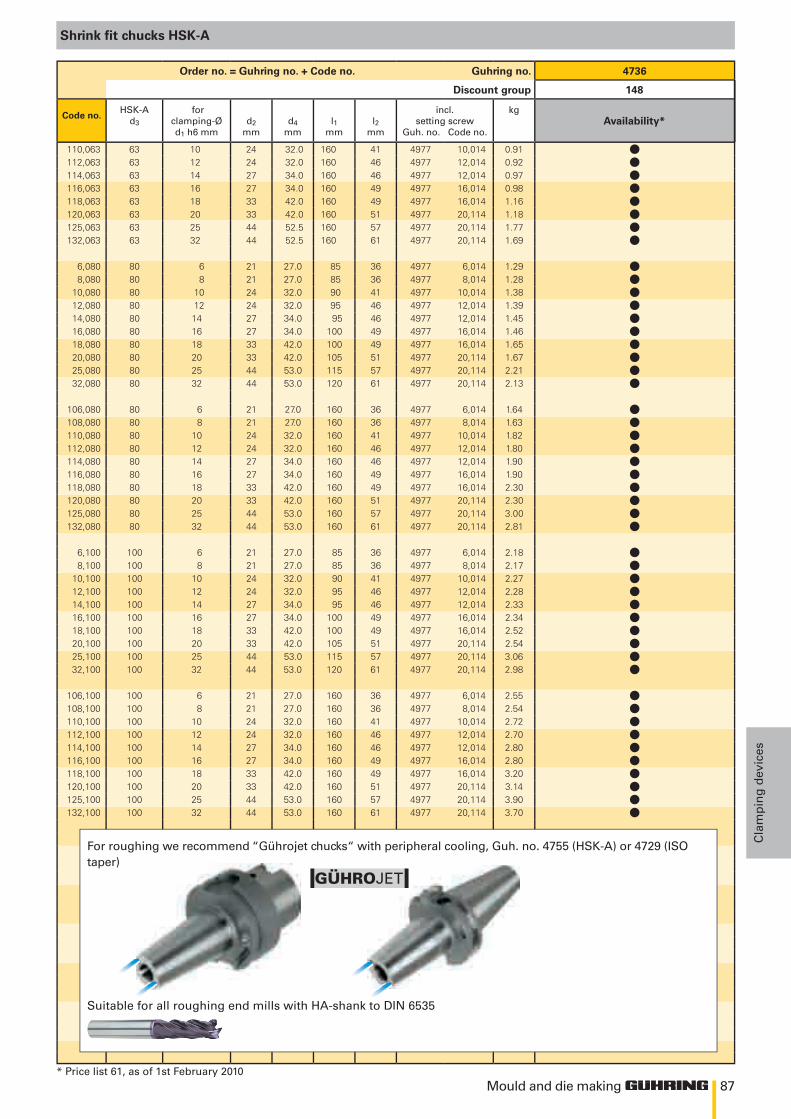
87
GÜHROJET
Mould and die making
Cla
mp
ing
dev
ices
Shrink fit chucks HSK-A
Order no. = Guhring no. + Code no. Guhring no. 4736
Discount group 148
Code no.HSK-A
d3 for
clamping-Ød1 h6 mm
d2mm
d4mm
l1mm
l2mm
incl.setting screw
Guh. no. Code no.
kg
110,063 63 10 24 32.0 160 41 4977 10,014 0.91112,063 63 12 24 32.0 160 46 4977 12,014 0.92114,063 63 14 27 34.0 160 46 4977 12,014 0.97116,063 63 16 27 34.0 160 49 4977 16,014 0.98118,063 63 18 33 42.0 160 49 4977 16,014 1.16120,063 63 20 33 42.0 160 51 4977 20,114 1.18125,063 63 25 44 52.5 160 57 4977 20,114 1.77132,063 63 32 44 52.5 160 61 4977 20,114 1.69
6,080 80 6 21 27.0 85 36 4977 6,014 1.298,080 80 8 21 27.0 85 36 4977 8,014 1.28
10,080 80 10 24 32.0 90 41 4977 10,014 1.3812,080 80 12 24 32.0 95 46 4977 12,014 1.3914,080 80 14 27 34.0 95 46 4977 12,014 1.4516,080 80 16 27 34.0 100 49 4977 16,014 1.4618,080 80 18 33 42.0 100 49 4977 16,014 1.6520,080 80 20 33 42.0 105 51 4977 20,114 1.6725,080 80 25 44 53.0 115 57 4977 20,114 2.2132,080 80 32 44 53.0 120 61 4977 20,114 2.13
106,080 80 6 21 27.0 160 36 4977 6,014 1.64108,080 80 8 21 27.0 160 36 4977 8,014 1.63110,080 80 10 24 32.0 160 41 4977 10,014 1.82112,080 80 12 24 32.0 160 46 4977 12,014 1.80114,080 80 14 27 34.0 160 46 4977 12,014 1.90116,080 80 16 27 34.0 160 49 4977 16,014 1.90118,080 80 18 33 42.0 160 49 4977 16,014 2.30120,080 80 20 33 42.0 160 51 4977 20,114 2.30125,080 80 25 44 53.0 160 57 4977 20,114 3.00132,080 80 32 44 53.0 160 61 4977 20,114 2.81
6,100 100 6 21 27.0 85 36 4977 6,014 2.18 8,100 100 8 21 27.0 85 36 4977 8,014 2.1710,100 100 10 24 32.0 90 41 4977 10,014 2.2712,100 100 12 24 32.0 95 46 4977 12,014 2.2814,100 100 14 27 34.0 95 46 4977 12,014 2.3316,100 100 16 27 34.0 100 49 4977 16,014 2.3418,100 100 18 33 42.0 100 49 4977 16,014 2.5220,100 100 20 33 42.0 105 51 4977 20,114 2.5425,100 100 25 44 53.0 115 57 4977 20,114 3.0632,100 100 32 44 53.0 120 61 4977 20,114 2.98
106,100 100 6 21 27.0 160 36 4977 6,014 2.55108,100 100 8 21 27.0 160 36 4977 8,014 2.54110,100 100 10 24 32.0 160 41 4977 10,014 2.72112,100 100 12 24 32.0 160 46 4977 12,014 2.70114,100 100 14 27 34.0 160 46 4977 12,014 2.80116,100 100 16 27 34.0 160 49 4977 16,014 2.80118,100 100 18 33 42.0 160 49 4977 16,014 3.20120,100 100 20 33 42.0 160 51 4977 20,114 3.14125,100 100 25 44 53.0 160 57 4977 20,114 3.90132,100 100 32 44 53.0 160 61 4977 20,114 3.70
For roughing we recommend “Gührojet chucks“ with peripheral cooling, Guh. no. 4755 (HSK-A) or 4729 (ISO taper)
Suitable for all roughing end mills with HA-shank to DIN 6535
* Price list 61, as of 1st February 2010
Availability*
llllllll
llllllllll
llllllllll
llllllllll
llllllllll

88
10
SK
d 2
l 2
l 1
d 1 d 3
A 4°
30'
2,5 x d
0,003 A
1
Mould and die making
Clam
pin
g d
evices
Guhring no. 4738O
rder
no.
= G
uh
rin
g n
o. +
co
de
no.
Discount group 148
Product information• balancing quality G6.3 / 15,000 rev./min• for ISO40/50 to DIN 69871 form AD/B• form B supplied with threaded pins in bores• for tool shank tolerance h6• also available in the lengths l1 = 120 mm and 160 mm (concentricity 5 μm)
Scope of delivery• incl. setting screw Guhring no. 4977 or 4904 respectively
• order draw bolt Guhring nos. 4925, 4926 separately
• special dimensions on request
Code no. ISO taper
forclamping-Ød1 h6 mm
d2mm
d4mm
l1mm
l2mm
incl.setting screw
Guh. no. Code no.
kg
3,040 40 3 10 18 80 30 4904 5,016 0.90 4,040 40 4 10 18 80 35 4904 6,016 0.90 5,040 40 5 10 18 80 40 4904 8,018 0.90 6,040 40 6 21 27 80 36 4977 6,014 1.00 8,040 40 8 21 27 80 36 4977 8,014 1.0010,040 40 10 24 32 80 41 4977 10,014 1.1012,040 40 12 24 32 80 46 4977 12,014 1.0016,040 40 16 27 34 80 49 4977 16,014 1.1020,040 40 20 33 42 80 51 4977 20,114 1.50
203,040 40 3 10 24 120 30 4904 5,016 1.00204,040 40 4 10 24 120 35 4904 6,016 1.00205,040 40 5 10 24 120 40 4904 8,018 1.00206,040 40 6 21 27 120 36 4977 6,014 1.10208,040 40 8 21 27 120 36 4977 8,014 1.10210,040 40 10 24 32 120 41 4977 10,014 1.20212,040 40 12 24 32 120 46 4977 12,014 1.20216,040 40 16 27 34 120 49 4977 16,014 1.35220,040 40 20 33 42 120 51 4977 20,114 1.50
103,040 40 3 10 31 160 30 4904 5,016 1.10104,040 40 4 10 31 160 35 4904 6,016 1.10105,040 40 5 10 31 160 40 4904 8,018 1.10106,040 40 6 21 27 160 36 4977 6,014 1.30108,040 40 8 21 27 160 36 4977 8,014 1.30110,040 40 10 24 32 160 41 4977 10,014 1.50112,040 40 12 24 32 160 46 4977 12,014 1.50116,040 40 16 27 34 160 49 4977 16,014 1.70120,040 40 20 33 42 160 51 4977 20,114 1.90
3,050 50 3 10 18 80 30 4904 5,016 2.60 4,050 50 4 10 18 80 35 4904 6,016 2.60 5,050 50 5 10 18 80 40 4904 8,018 2.60 6,050 50 6 21 27 80 36 4977 6,014 2.90 8,050 50 8 21 27 80 36 4977 8,014 2.9010,050 50 10 24 32 80 41 4977 10,014 2.9012,050 50 12 24 32 80 46 4977 12,014 2.9016,050 50 16 27 34 80 49 4977 16,014 3.0020,050 50 20 33 42 80 51 4977 20,114 3.00
106,050 50 6 21 27 160 36 4977 6,014 3.10108,050 50 8 21 27 160 36 4977 8,014 3.10110,050 50 10 24 32 160 41 4977 10,014 3.40112,050 50 12 24 32 160 46 4977 12,014 3.40116,050 50 16 27 34 160 49 4977 16,014 3.70120,050 50 20 33 42 160 51 4977 20,114 4.10
Diameters 14, 18, 25 and 32 mm are also available ex-stock.
Shrink fit chucks ISO taper DIN 69871 form AD/B
* Price list 61, as of 1st February 2010
Availability*
lllllllll
llllllll
lllllllll
lllllllll
llllll
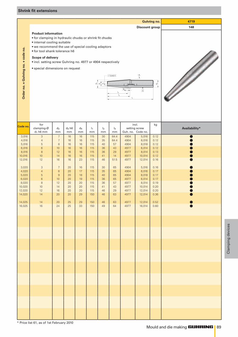
89
d2
l2
l1
d1
d3
A
0,003 A
4 o
l3d
4
10
Mould and die making
Cla
mp
ing
dev
ices
Shrink fit extensions
Guhring no. 4719O
rder
no.
= G
uh
rin
g n
o. +
co
de
no.
Discount group 148
Product information• for clamping in hydraulic chucks or shrink fit chucks• internal cooling suitable• we recommend the use of special cooling adaptors• for tool shank tolerance h6
Scope of delivery• incl. setting screw Guhring no. 4977 or 4904 respectively
• special dimensions on request
Code no. for
clamping-Ød1 h6 mm
d2
mmd3 h6mm
d4
mml1
mml2
mml3
mm
incl.setting screw
Guh. no. Code no.
kg
3,016 3 7 16 16 115 30 64.4 4904 5,016 0.12 4,016 4 7 16 16 115 35 64.4 4904 6,016 0.12 5,016 5 8 16 16 115 40 57 4904 8,018 0.12 6,016 6 10 16 16 115 36 43 4977 6,014 0.12 8,016 8 12 16 16 115 36 29 4977 8,014 0.1310,016 10 14 16 16 115 41 14 4977 10,014 0.1212,016 12 16 16 23 115 46 51.5 4977 12,014 0.16
3,020 3 7 20 16 115 30 65 4904 5,016 0.16 4,020 4 8 20 17 115 35 65 4904 6,016 0.17 5,020 5 9 20 18 115 40 65 4904 8,018 0.17 6,020 6 10 20 19 115 36 65 4977 6,014 0.17 8,020 8 12 20 20 115 36 57 4977 8,014 0.1910,020 10 14 20 20 115 41 43 4977 10,014 0.2012,020 12 16 20 20 115 46 29 4977 12,014 0.2014,020 14 20 20 29 150 46 63 4977 12,014 0.36
14,025 14 20 25 29 150 46 63 4977 12,014 0.5216,025 16 24 25 33 150 49 64 4977 16,014 0.60
* Price list 61, as of 1st February 2010
Availability*
lllllll
llllllll
ll
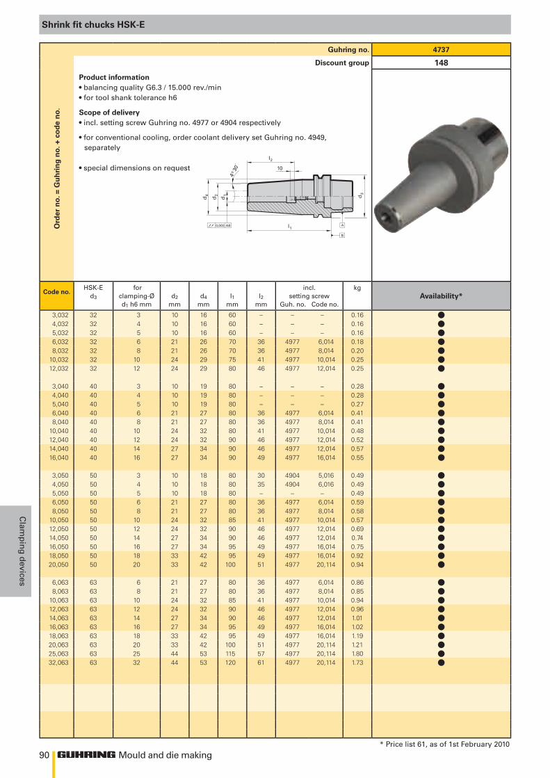
90
l1
d1
d2
10
l2
4o 3
0´
d4
0,003 AB A
d3
B
Mould and die making
Clam
pin
g d
evices
Shrink fit chucks HSK-E
Guhring no. 4737O
rder
no.
= G
uh
rin
g n
o. +
co
de
no.
Discount group 148
Product information• balancing quality G6.3 / 15.000 rev./min• for tool shank tolerance h6
Scope of delivery• incl. setting screw Guhring no. 4977 or 4904 respectively
• for conventional cooling, order coolant delivery set Guhring no. 4949,separately
• special dimensions on request
Code no.HSK-E
d3 for
clamping-Ød1 h6 mm
d2
mmd4
mml1
mml2
mm
incl.setting screw
Guh. no. Code no.
kg
3,032 32 3 10 16 60 – – – 0.164,032 32 4 10 16 60 – – – 0.165,032 32 5 10 16 60 – – – 0.166,032 32 6 21 26 70 36 4977 6,014 0.188,032 32 8 21 26 70 36 4977 8,014 0.20
10,032 32 10 24 29 75 41 4977 10,014 0.2512,032 32 12 24 29 80 46 4977 12,014 0.25
3,040 40 3 10 19 80 – – – 0.284,040 40 4 10 19 80 – – – 0.285,040 40 5 10 19 80 – – – 0.276,040 40 6 21 27 80 36 4977 6,014 0.418,040 40 8 21 27 80 36 4977 8,014 0.41
10,040 40 10 24 32 80 41 4977 10,014 0.4812,040 40 12 24 32 90 46 4977 12,014 0.5214,040 40 14 27 34 90 46 4977 12,014 0.5716,040 40 16 27 34 90 49 4977 16,014 0.55
3,050 50 3 10 18 80 30 4904 5,016 0.494,050 50 4 10 18 80 35 4904 6,016 0.495,050 50 5 10 18 80 – – – 0.496,050 50 6 21 27 80 36 4977 6,014 0.598,050 50 8 21 27 80 36 4977 8,014 0.58
10,050 50 10 24 32 85 41 4977 10,014 0.5712,050 50 12 24 32 90 46 4977 12,014 0.6914,050 50 14 27 34 90 46 4977 12,014 0.7416,050 50 16 27 34 95 49 4977 16,014 0.7518,050 50 18 33 42 95 49 4977 16,014 0.9220,050 50 20 33 42 100 51 4977 20,114 0.94
6,063 63 6 21 27 80 36 4977 6,014 0.868,063 63 8 21 27 80 36 4977 8,014 0.85
10,063 63 10 24 32 85 41 4977 10,014 0.9412,063 63 12 24 32 90 46 4977 12,014 0.9614,063 63 14 27 34 90 46 4977 12,014 1.0116,063 63 16 27 34 95 49 4977 16,014 1.0218,063 63 18 33 42 95 49 4977 16,014 1.1920,063 63 20 33 42 100 51 4977 20,114 1.2125,063 63 25 44 53 115 57 4977 20,114 1.8032,063 63 32 44 53 120 61 4977 20,114 1.73
* Price list 61, as of 1st February 2010
Availability*
lllllll
lllllllll
lllllllllll
llllllllll
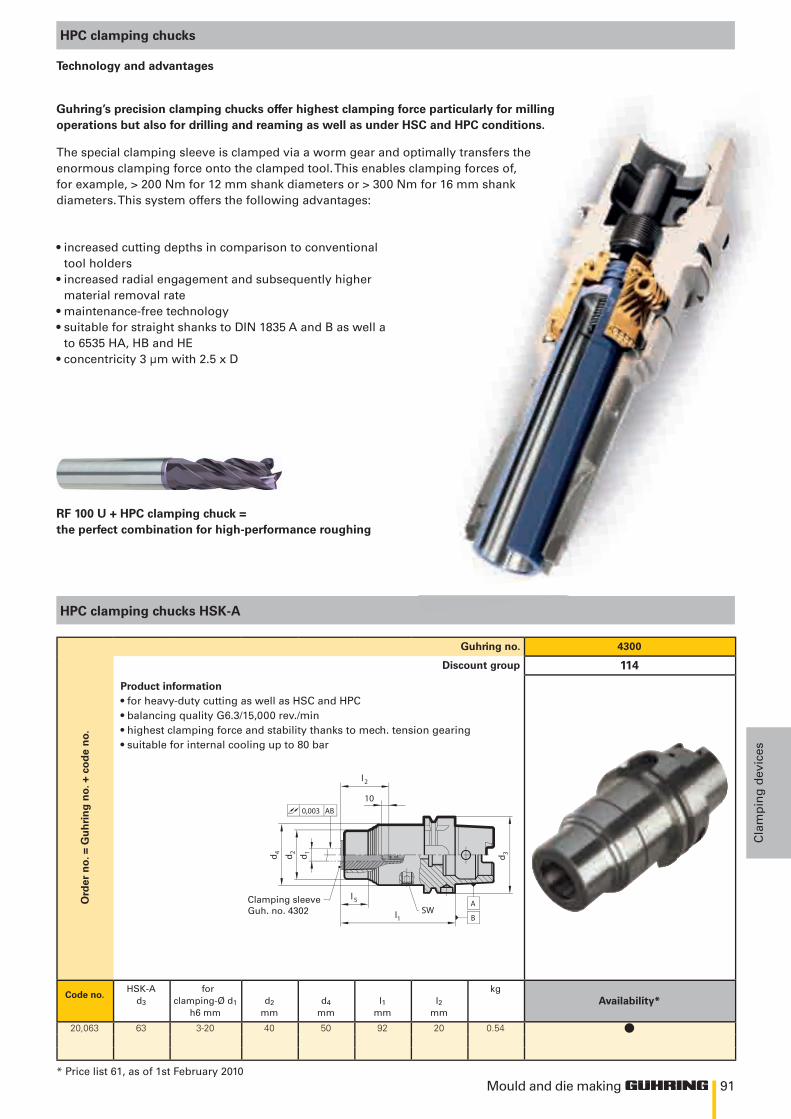
91
SWl1
d 1d 2d 4 d 3
0,003 AB
l5
10
l2
A
B
Mould and die making
Cla
mp
ing
dev
ices
HPC clamping chucks
Technology and advantages
• increased cutting depths in comparison to conventional tool holders
• increased radial engagement and subsequently higher material removal rate
• maintenance-free technology• suitable for straight shanks to DIN 1835 A and B as well a
to 6535 HA, HB and HE• concentricity 3 μm with 2.5 x D
Guhring’s precision clamping chucks offer highest clamping force particularly for millingoperations but also for drilling and reaming as well as under HSC and HPC conditions.
The special clamping sleeve is clamped via a worm gear and optimally transfers theenormous clamping force onto the clamped tool. This enables clamping forces of, for example, > 200 Nm for 12 mm shank diameters or > 300 Nm for 16 mm shank diameters. This system offers the following advantages:
HPC clamping chucks HSK-A
Clamping sleeveGuh. no. 4302
* Price list 61, as of 1st February 2010
Guhring no. 4300
Ord
er n
o. =
Gu
hri
ng
no.
+ c
od
e n
o.
Discount group 114
Product information• for heavy-duty cutting as well as HSC and HPC• balancing quality G6.3/15,000 rev./min• highest clamping force and stability thanks to mech. tension gearing• suitable for internal cooling up to 80 bar
Code no.HSK-A
d3
forclamping-Ø d1
h6 mmd2
mmd4
mml1
mml2
mm
kg
20,063 63 3-20 40 50 92 20 0.54
RF 100 U + HPC clamping chuck =the perfect combination for high-performance roughing
Availability*
l
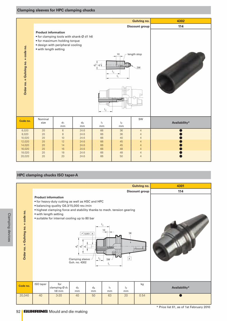
92
SW
l1
d 1
l 2
d 2
l 2
10
SW
l1
d 1d 2d 4
0,003 A
l5
10
l2
A
SK
Mould and die making
Clam
pin
g d
evices
Clamping sleeves for HPC clamping chucks
HPC clamping chucks ISO taper-A
Guhring no. 4302O
rder
no.
= G
uh
rin
g n
o. +
co
de
no.
Discount group 114
Product information• for clamping tools with shank-Ø d1 h6• for maximum holding torque• design with peripheral cooling• with length setting
Code no.Nominal
size d1
mmd2
mml1
mml2
mm
SW
6,020 20 6 24.6 66 36 48,020 20 8 24.6 66 36 410,020 20 10 24.6 66 40 412,020 20 12 24.6 66 45 414,020 20 14 24.6 66 45 416,020 20 16 24.6 66 48 418,020 20 18 24.6 66 48 420,020 20 20 24.6 66 50 4
Guhring no. 4301
Ord
er n
o. =
Gu
hri
ng
no.
+ c
od
e n
o.
Discount group 114
Product information• for heavy-duty cutting as well as HSC and HPC• balancing quality G6.3/15,000 rev./min• highest clamping force and stability thanks to mech. tension gearing• with length setting• suitable for internal cooling up to 80 bar
Code no.ISO taper for
clamping-Ø d1 h6 mm
d2
mmd4
mml1
mml2
mm
kg
20,040 40 3-20 40 50 63 20 0.54
length stop
Clamping sleeveGuh. no. 4302
holder (optional)HSK Guhring no. 4745 or SK Guhring no. 4744
* Price list 61, as of 1st February 2010
Availability*
llllllll
Availability*
l
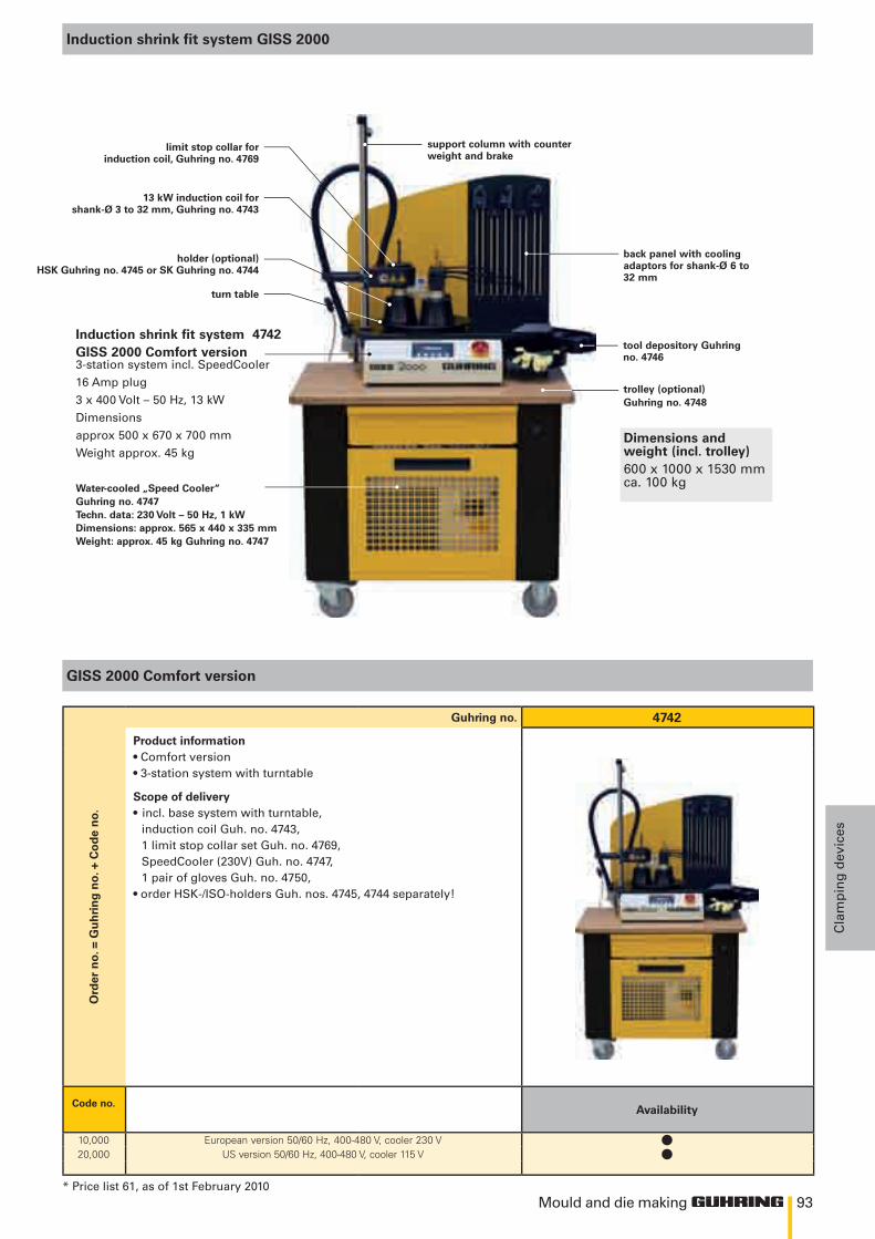
93Mould and die making
Cla
mp
ing
dev
ices
Induction shrink fit system GISS 2000
GISS 2000 Comfort version
Guhring no. 4742
Ord
er n
o. =
Gu
hri
ng
no.
+ C
od
e n
o.
Product information• Comfort version• 3-station system with turntable
Scope of delivery• incl. base system with turntable,
induction coil Guh. no. 4743,1 limit stop collar set Guh. no. 4769,SpeedCooler (230V) Guh. no. 4747,1 pair of gloves Guh. no. 4750,
• order HSK-/ISO-holders Guh. nos. 4745, 4744 separately!
Code no.
10,000 European version 50/60 Hz, 400-480 V, cooler 230 V20,000 US version 50/60 Hz, 400-480 V, cooler 115 V
Water-cooled „Speed Cooler“Guhring no. 4747Techn. data: 230 Volt – 50 Hz, 1 kWDimensions: approx. 565 x 440 x 335 mmWeight: approx. 45 kg Guhring no. 4747
3-station system incl. SpeedCooler
16 Amp plug
3 x 400 Volt – 50 Hz, 13 kW
Dimensions
approx 500 x 670 x 700 mm
Weight approx. 45 kg
trolley (optional)Guhring no. 4748
turn table
tool depository Guhringno. 4746
back panel with coolingadaptors for shank-Ø 6 to32 mm
holder (optional)HSK Guhring no. 4745 or SK Guhring no. 4744
13 kW induction coil forshank-Ø 3 to 32 mm, Guhring no. 4743
limit stop collar forinduction coil, Guhring no. 4769
support column with counterweight and brake
Dimensions andweight (incl. trolley)600 x 1000 x 1530 mmca. 100 kg
Induction shrink fit systemGISS 2000 Comfort version
4742
* Price list 61, as of 1st February 2010
Availability
ll

Mould and die MakingnaviGator
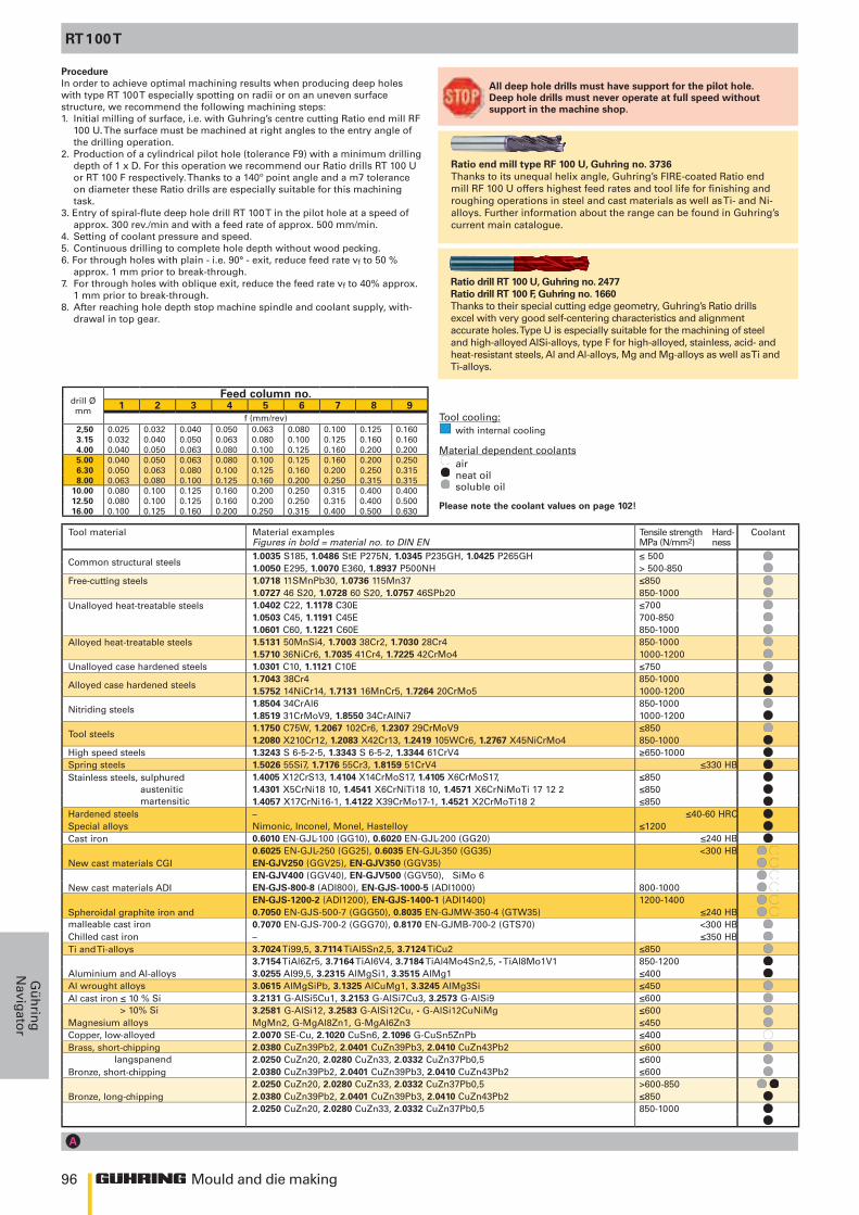
96
1 2 3 4 5 6 7 8 9
15 x D 20 x D 25 x D 30 x D 40 x D6509 6511 6512 6513 6514
110 8 110 8 100 8 80 7 80 7110 8 110 8 100 8 80 7 80 7120 8 120 8 120 8 100-120 8 100 8120 8 120 8 100 8 100 8 100 8110 6 110 6 110 6 110 6 110 6110 8 110 8 100 8 80 7 80 7100 7 100 7 100 7 80 7 80 7110 7 80 7 110 7 80 7 100 7 70 7 80 7 60 6-7 80 6-7110 6 80 7 110 6 80 7 100 6 70 7 80 6 60 6 80 6110 8 110 8 100 8 80 7 80 7110 7 80 6-7 110 7 80 6-7 100 7 70 6-7 80 6 60 6-7 80 6110 6 80 6-7 110 6 80 6-7 100 6 70 6-7 80 6 60 6-7 80 6100 5 100 5 80 5 80 5 80 580 5 80 5 60 5 60 5 60 5100 6-7 100 6-7 90 6-7 80 6-7 80 6-780 5 80 5 70 4 70 4 70 450 5 50 5 50 4 50 4 50 450 5 50 5 50 4 50 4 50 4100 5 100 5 100 5 80 5 80 5
60-80 2-3 60-80 2-3 60-80 2-3 60-80 2-3 60-80 2-3100 5 100 5 100 5 80 5 80 550 4 50 4 50 4 50 4 50 4
30 2 30 2 30 2 30 2 30 2140 8 140 8 130 8 120 8 120 8100 8 100 8 90 8 80 8 80 8100 6 100 6 90 6 80 6 80 6100 6 100 6 90 6 80 6 80 690 8 90 8 90 8 90 8 80 8 80 8 70 8 70 8 70 8
140 8 140 8 130 8 120 8 120 8100 8 100 8 90 8 80 8 65 8 80 8
120 1 120 1 120 1 120 1 120 1120 8 120 8 110 8 100 8 100 8
Mould and die making
Gü
hrin
gN
avigator
All deep hole drills must have support for the pilot hole. Deep hole drills must never operate at full speed without support in the machine shop.
ProcedureIn order to achieve optimal machining results when producing deep holes with type RT 100 T especially spotting on radii or on an uneven surface structure, we recommend the following machining steps:1. Initial milling of surface, i.e. with Guhring’s centre cutting Ratio end mill RF
100 U. The surface must be machined at right angles to the entry angle of the drilling operation.
2. Production of a cylindrical pilot hole (tolerance F9) with a minimum drilling depth of 1 x D. For this operation we recommend our Ratio drills RT 100 U or RT 100 F respectively. Thanks to a 140º point angle and a m7 tolerance on diameter these Ratio drills are especially suitable for this machining task.
3. Entry of spiral-flute deep hole drill RT 100 T in the pilot hole at a speed of approx. 300 rev./min and with a feed rate of approx. 500 mm/min.
4. Setting of coolant pressure and speed.5. Continuous drilling to complete hole depth without wood pecking.6. For through holes with plain - i.e. 90° - exit, reduce feed rate vf to 50 % approx. 1 mm prior to break-through.7. For through holes with oblique exit, reduce the feed rate vf to 40% approx.
1 mm prior to break-through.8. After reaching hole depth stop machine spindle and coolant supply, with-
drawal in top gear.
RT 100 T
Tool cooling: with internal cooling
Material dependent coolants air neat oil soluble oil
Please note the coolant values on page 102!
Ratio drill RT 100 U, Guhring no. 2477Ratio drill RT 100 F, Guhring no. 1660Thanks to their special cutting edge geometry, Guhring’s Ratio drills excel with very good self-centering characteristics and alignment accurate holes. Type U is especially suitable for the machining of steel and high-alloyed AlSi-alloys, type F for high-alloyed, stainless, acid- and heat-resistant steels, Al and Al-alloys, Mg and Mg-alloys as well as Ti and Ti-alloys.
Ratio end mill type RF 100 U, Guhring no. 3736Thanks to its unequal helix angle, Guhring’s FIRE-coated Ratio end mill RF 100 U offers highest feed rates and tool life for finishing and roughing operations in steel and cast materials as well as Ti- and Ni-alloys. Further information about the range can be found in Guhring’s current main catalogue.
Tool material Material examplesFigures in bold = material no. to DIN EN
Tensile strength Hard-MPa (N/mm2) ness
Coolant
Common structural steels1.0035 S185, 1.0486 StE P275N, 1.0345 P235GH, 1.0425 P265GH ≤ 5001.0050 E295, 1.0070 E360, 1.8937 P500NH > 500-850
Free-cutting steels 1.0718 11SMnPb30, 1.0736 115Mn37 ≤8501.0727 46 S20, 1.0728 60 S20, 1.0757 46SPb20 850-1000
Unalloyed heat-treatable steels 1.0402 C22, 1.1178 C30E ≤7001.0503 C45, 1.1191 C45E 700-8501.0601 C60, 1.1221 C60E 850-1000
Alloyed heat-treatable steels 1.5131 50MnSi4, 1.7003 38Cr2, 1.7030 28Cr4 850-10001.5710 36NiCr6, 1.7035 41Cr4, 1.7225 42CrMo4 1000-1200
Unalloyed case hardened steels 1.0301 C10, 1.1121 C10E ≤750
Alloyed case hardened steels1.7043 38Cr4 850-10001.5752 14NiCr14, 1.7131 16MnCr5, 1.7264 20CrMo5 1000-1200
Nitriding steels1.8504 34CrAl6 850-10001.8519 31CrMoV9, 1.8550 34CrAlNi7 1000-1200
Tool steels1.1750 C75W, 1.2067 102Cr6, 1.2307 29CrMoV9 ≤8501.2080 X210Cr12, 1.2083 X42Cr13, 1.2419 105WCr6, 1.2767 X45NiCrMo4 850-1000
High speed steels 1.3243 S 6-5-2-5, 1.3343 S 6-5-2, 1.3344 61CrV4 ≥650-1000Spring steels 1.5026 55Si7, 1.7176 55Cr3, 1.8159 51CrV4 ≤330 HBStainless steels, sulphured austenitic martensitic
1.4005 X12CrS13, 1.4104 X14CrMoS17, 1.4105 X6CrMoS17, ≤8501.4301 X5CrNi18 10, 1.4541 X6CrNiTi18 10, 1.4571 X6CrNiMoTi 17 12 2 ≤8501.4057 X17CrNi16-1, 1.4122 X39CrMo17-1, 1.4521 X2CrMoTi18 2 ≤850
Hardened steels – ≤40-60 HRCSpecial alloys Nimonic, Inconel, Monel, Hastelloy ≤1200Cast iron 0.6010 EN-GJL-100 (GG10), 0.6020 EN-GJL-200 (GG20) ≤240 HB
0.6025 EN-GJL-250 (GG25), 0.6035 EN-GJL-350 (GG35) <300 HBNew cast materials CGI EN-GJV250 (GGV25), EN-GJV350 (GGV35)
EN-GJV400 (GGV40), EN-GJV500 (GGV50), SiMo 6New cast materials ADI EN-GJS-800-8 (ADI800), EN-GJS-1000-5 (ADI1000) 800-1000
EN-GJS-1200-2 (ADI1200), EN-GJS-1400-1 (ADI1400) 1200-1400Spheroidal graphite iron andmalleable cast iron
0.7050 EN-GJS-500-7 (GGG50), 0.8035 EN-GJMW-350-4 (GTW35) ≤240 HB0.7070 EN-GJS-700-2 (GGG70), 0.8170 EN-GJMB-700-2 (GTS70) <300 HB
Chilled cast iron – ≤350 HBTi and Ti-alloys 3.7024 Ti99,5, 3.7114 TiAl5Sn2,5, 3.7124 TiCu2 ≤850
3.7154 TiAl6Zr5, 3.7164 TiAl6V4, 3.7184 TiAl4Mo4Sn2,5, - TiAl8Mo1V1 850-1200Aluminium and Al-alloys 3.0255 Al99,5, 3.2315 AlMgSi1, 3.3515 AlMg1 ≤400Al wrought alloys 3.0615 AlMgSiPb, 3.1325 AlCuMg1, 3.3245 AlMg3Si ≤450Al cast iron ≤ 10 % Si > 10% Si
3.2131 G-AlSi5Cu1, 3.2153 G-AlSi7Cu3, 3.2573 G-AlSi9 ≤6003.2581 G-AlSi12, 3.2583 G-AlSi12Cu, - G-AlSi12CuNiMg ≤600
Magnesium alloys MgMn2, G-MgAl8Zn1, G-MgAl6Zn3 ≤450Copper, low-alloyed 2.0070 SE-Cu, 2.1020 CuSn6, 2.1096 G-CuSn5ZnPb ≤400Brass, short-chipping langspanend
2.0380 CuZn39Pb2, 2.0401 CuZn39Pb3, 2.0410 CuZn43Pb2 ≤6002.0250 CuZn20, 2.0280 CuZn33, 2.0332 CuZn37Pb0,5 ≤600
Bronze, short-chipping
2.0380 CuZn39Pb2, 2.0401 CuZn39Pb3, 2.0410 CuZn43Pb2 ≤6002.0250 CuZn20, 2.0280 CuZn33, 2.0332 CuZn37Pb0,5 >600-850
Bronze, long-chipping 2.0380 CuZn39Pb2, 2.0401 CuZn39Pb3, 2.0410 CuZn43Pb2 ≤8502.0250 CuZn20, 2.0280 CuZn33, 2.0332 CuZn37Pb0,5 850-1000
drill Ø mm
Feed column no.
f (mm/rev)2,50 0.025 0.032 0.040 0.050 0.063 0.080 0.100 0.125 0.1603.15 0.032 0.040 0.050 0.063 0.080 0.100 0.125 0.160 0.1604.00 0.040 0.050 0.063 0.080 0.100 0.125 0.160 0.200 0.2005.00 0.040 0.050 0.063 0.080 0.100 0.125 0.160 0.200 0.2506.30 0.050 0.063 0.080 0.100 0.125 0.160 0.200 0.250 0.3158.00 0.063 0.080 0.100 0.125 0.160 0.200 0.250 0.315 0.315
10.00 0.080 0.100 0.125 0.160 0.200 0.250 0.315 0.400 0.40012.50 0.080 0.100 0.125 0.160 0.200 0.250 0.315 0.400 0.50016.00 0.100 0.125 0.160 0.200 0.250 0.315 0.400 0.500 0.630
Guhring no.
Standard Guhring standard Guhring standard Guhring standard Guhring standard Guhring standard
Tool material Solid carbide Solid carbide Solid carbide Solid carbide Solid carbideCarbide grade K30/K40 K30/K40 K30/K40 K30/K40 K30/K40
Surface TiAlN head coated TiAlN head coated TiAlN head coated TiAlN head coated TiAlN head coated
Type RT 100 T RT 100 T RT 100 T RT 100 T RT 100 T
Shank HA HA HA HA HA
Cutting direction right-hand right-hand right-hand right-hand right-hand
Coolant
conventionalcooling
min. 40 bar
conventionalcooling
min. 40 bar
conventionalcooling
min. 40 bar
conventionalcooling
min. 40 bar
conventionalcooling min. 40 bar
Vc(m/min)
Feedcol.no.
Vc(m/min)
Feedcol.no.
Vc(m/min)
Feedcol.no.
Vc(m/min)
Feedcol.no.
Vc(m/min)
Feedcol.no.
Vc(m/min)
Feedcol.no.
Vc(m/min)
Feedcol.no.
Vc(m/min)
Feedcol.no.
Vc(m/min)
Feedcol.no.
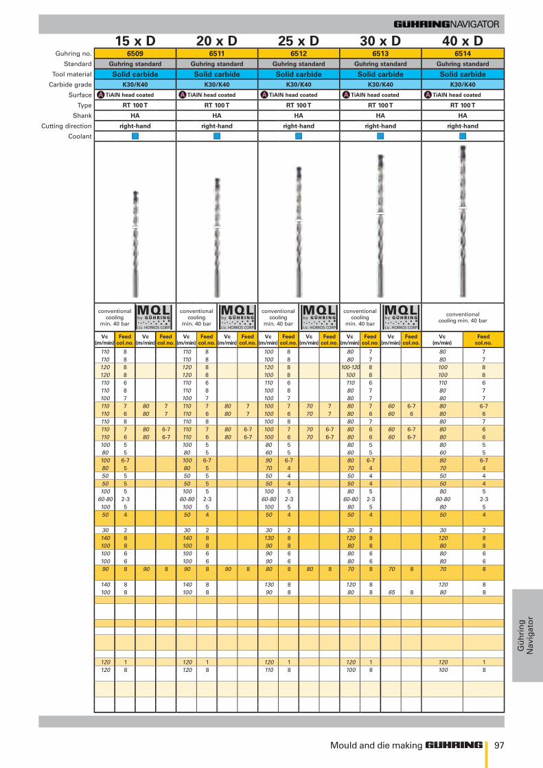
97
15 x D 20 x D 25 x D 30 x D 40 x D6509 6511 6512 6513 6514
110 8 110 8 100 8 80 7 80 7110 8 110 8 100 8 80 7 80 7120 8 120 8 120 8 100-120 8 100 8120 8 120 8 100 8 100 8 100 8110 6 110 6 110 6 110 6 110 6110 8 110 8 100 8 80 7 80 7100 7 100 7 100 7 80 7 80 7110 7 80 7 110 7 80 7 100 7 70 7 80 7 60 6-7 80 6-7110 6 80 7 110 6 80 7 100 6 70 7 80 6 60 6 80 6110 8 110 8 100 8 80 7 80 7110 7 80 6-7 110 7 80 6-7 100 7 70 6-7 80 6 60 6-7 80 6110 6 80 6-7 110 6 80 6-7 100 6 70 6-7 80 6 60 6-7 80 6100 5 100 5 80 5 80 5 80 580 5 80 5 60 5 60 5 60 5100 6-7 100 6-7 90 6-7 80 6-7 80 6-780 5 80 5 70 4 70 4 70 450 5 50 5 50 4 50 4 50 450 5 50 5 50 4 50 4 50 4100 5 100 5 100 5 80 5 80 5
60-80 2-3 60-80 2-3 60-80 2-3 60-80 2-3 60-80 2-3100 5 100 5 100 5 80 5 80 550 4 50 4 50 4 50 4 50 4
30 2 30 2 30 2 30 2 30 2140 8 140 8 130 8 120 8 120 8100 8 100 8 90 8 80 8 80 8100 6 100 6 90 6 80 6 80 6100 6 100 6 90 6 80 6 80 690 8 90 8 90 8 90 8 80 8 80 8 70 8 70 8 70 8
140 8 140 8 130 8 120 8 120 8100 8 100 8 90 8 80 8 65 8 80 8
120 1 120 1 120 1 120 1 120 1120 8 120 8 110 8 100 8 100 8
Mould and die making
Gü
hri
ng
Nav
igat
or
Tool material Material examplesFigures in bold = material no. to DIN EN
Tensile strength Hard-MPa (N/mm2) ness
Coolant
Common structural steels1.0035 S185, 1.0486 StE P275N, 1.0345 P235GH, 1.0425 P265GH ≤ 5001.0050 E295, 1.0070 E360, 1.8937 P500NH > 500-850
Free-cutting steels 1.0718 11SMnPb30, 1.0736 115Mn37 ≤8501.0727 46 S20, 1.0728 60 S20, 1.0757 46SPb20 850-1000
Unalloyed heat-treatable steels 1.0402 C22, 1.1178 C30E ≤7001.0503 C45, 1.1191 C45E 700-8501.0601 C60, 1.1221 C60E 850-1000
Alloyed heat-treatable steels 1.5131 50MnSi4, 1.7003 38Cr2, 1.7030 28Cr4 850-10001.5710 36NiCr6, 1.7035 41Cr4, 1.7225 42CrMo4 1000-1200
Unalloyed case hardened steels 1.0301 C10, 1.1121 C10E ≤750
Alloyed case hardened steels1.7043 38Cr4 850-10001.5752 14NiCr14, 1.7131 16MnCr5, 1.7264 20CrMo5 1000-1200
Nitriding steels1.8504 34CrAl6 850-10001.8519 31CrMoV9, 1.8550 34CrAlNi7 1000-1200
Tool steels1.1750 C75W, 1.2067 102Cr6, 1.2307 29CrMoV9 ≤8501.2080 X210Cr12, 1.2083 X42Cr13, 1.2419 105WCr6, 1.2767 X45NiCrMo4 850-1000
High speed steels 1.3243 S 6-5-2-5, 1.3343 S 6-5-2, 1.3344 61CrV4 ≥650-1000Spring steels 1.5026 55Si7, 1.7176 55Cr3, 1.8159 51CrV4 ≤330 HBStainless steels, sulphured austenitic martensitic
1.4005 X12CrS13, 1.4104 X14CrMoS17, 1.4105 X6CrMoS17, ≤8501.4301 X5CrNi18 10, 1.4541 X6CrNiTi18 10, 1.4571 X6CrNiMoTi 17 12 2 ≤8501.4057 X17CrNi16-1, 1.4122 X39CrMo17-1, 1.4521 X2CrMoTi18 2 ≤850
Hardened steels – ≤40-60 HRCSpecial alloys Nimonic, Inconel, Monel, Hastelloy ≤1200Cast iron 0.6010 EN-GJL-100 (GG10), 0.6020 EN-GJL-200 (GG20) ≤240 HB
0.6025 EN-GJL-250 (GG25), 0.6035 EN-GJL-350 (GG35) <300 HBNew cast materials CGI EN-GJV250 (GGV25), EN-GJV350 (GGV35)
EN-GJV400 (GGV40), EN-GJV500 (GGV50), SiMo 6New cast materials ADI EN-GJS-800-8 (ADI800), EN-GJS-1000-5 (ADI1000) 800-1000
EN-GJS-1200-2 (ADI1200), EN-GJS-1400-1 (ADI1400) 1200-1400Spheroidal graphite iron andmalleable cast iron
0.7050 EN-GJS-500-7 (GGG50), 0.8035 EN-GJMW-350-4 (GTW35) ≤240 HB0.7070 EN-GJS-700-2 (GGG70), 0.8170 EN-GJMB-700-2 (GTS70) <300 HB
Chilled cast iron – ≤350 HBTi and Ti-alloys 3.7024 Ti99,5, 3.7114 TiAl5Sn2,5, 3.7124 TiCu2 ≤850
3.7154 TiAl6Zr5, 3.7164 TiAl6V4, 3.7184 TiAl4Mo4Sn2,5, - TiAl8Mo1V1 850-1200Aluminium and Al-alloys 3.0255 Al99,5, 3.2315 AlMgSi1, 3.3515 AlMg1 ≤400Al wrought alloys 3.0615 AlMgSiPb, 3.1325 AlCuMg1, 3.3245 AlMg3Si ≤450Al cast iron ≤ 10 % Si > 10% Si
3.2131 G-AlSi5Cu1, 3.2153 G-AlSi7Cu3, 3.2573 G-AlSi9 ≤6003.2581 G-AlSi12, 3.2583 G-AlSi12Cu, - G-AlSi12CuNiMg ≤600
Magnesium alloys MgMn2, G-MgAl8Zn1, G-MgAl6Zn3 ≤450Copper, low-alloyed 2.0070 SE-Cu, 2.1020 CuSn6, 2.1096 G-CuSn5ZnPb ≤400Brass, short-chipping langspanend
2.0380 CuZn39Pb2, 2.0401 CuZn39Pb3, 2.0410 CuZn43Pb2 ≤6002.0250 CuZn20, 2.0280 CuZn33, 2.0332 CuZn37Pb0,5 ≤600
Bronze, short-chipping
2.0380 CuZn39Pb2, 2.0401 CuZn39Pb3, 2.0410 CuZn43Pb2 ≤6002.0250 CuZn20, 2.0280 CuZn33, 2.0332 CuZn37Pb0,5 >600-850
Bronze, long-chipping 2.0380 CuZn39Pb2, 2.0401 CuZn39Pb3, 2.0410 CuZn43Pb2 ≤8502.0250 CuZn20, 2.0280 CuZn33, 2.0332 CuZn37Pb0,5 850-1000
Guhring no.
Standard Guhring standard Guhring standard Guhring standard Guhring standard Guhring standard
Tool material Solid carbide Solid carbide Solid carbide Solid carbide Solid carbideCarbide grade K30/K40 K30/K40 K30/K40 K30/K40 K30/K40
Surface TiAlN head coated TiAlN head coated TiAlN head coated TiAlN head coated TiAlN head coated
Type RT 100 T RT 100 T RT 100 T RT 100 T RT 100 T
Shank HA HA HA HA HA
Cutting direction right-hand right-hand right-hand right-hand right-hand
Coolant
conventionalcooling
min. 40 bar
conventionalcooling
min. 40 bar
conventionalcooling
min. 40 bar
conventionalcooling
min. 40 bar
conventionalcooling min. 40 bar
Vc(m/min)
Feedcol.no.
Vc(m/min)
Feedcol.no.
Vc(m/min)
Feedcol.no.
Vc(m/min)
Feedcol.no.
Vc(m/min)
Feedcol.no.
Vc(m/min)
Feedcol.no.
Vc(m/min)
Feedcol.no.
Vc(m/min)
Feedcol.no.
Vc(m/min)
Feedcol.no.
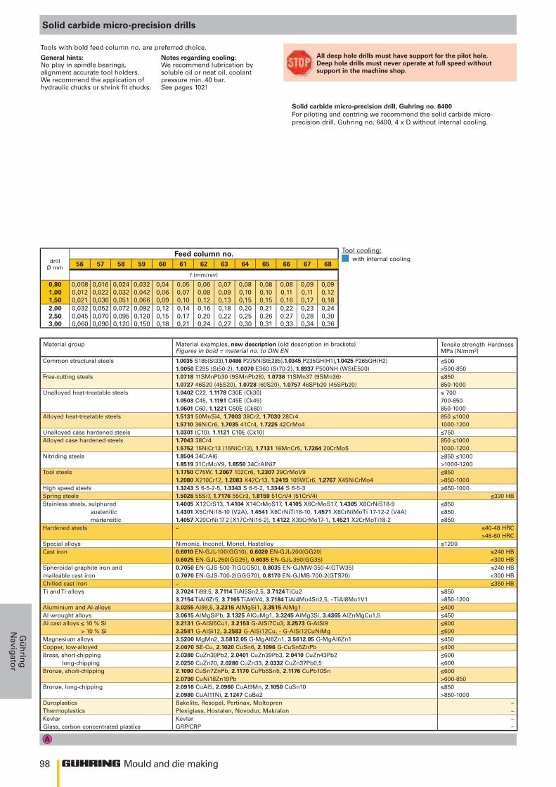
98
≤500>500-850≤850850-1000≤ 700700-850850-1000850 ≤10001000-1200≤750850 ≤10001000-1200≥850 ≤1000>1000-1200≤850>850-1000≥650-1000
≤330 HB≤850≤850≤850
≤40-48 HRC>48-60 HRC
≤1200≤240 HB<300 HB≤240 HB<300 HB≤350 HB
≤850 >850-1200≤400≤450≤600≤600≤450≤400≤600≤600≤600>600-850≤850>850-1000
––––
56 57 58 59 60 61 62 63 64 65 66 67 68
0,80 0,008 0,016 0,024 0,032 0,04 0,05 0,06 0,07 0,08 0,08 0,08 0,09 0,091,00 0,012 0,022 0,032 0,042 0,06 0,07 0,08 0,09 0,10 0,10 0,11 0,11 0,121,50 0,021 0,036 0,051 0,066 0,09 0,10 0,12 0,13 0,15 0,15 0,16 0,17 0,182,00 0,032 0,052 0,072 0,092 0,12 0,14 0,16 0,18 0,20 0,21 0,22 0,23 0,242,50 0,045 0,070 0,095 0,120 0,15 0,17 0,20 0,22 0,25 0,26 0,27 0,28 0,303,00 0,060 0,090 0,120 0,150 0,18 0,21 0,24 0,27 0,30 0,31 0,33 0,34 0,36
Mould and die making
Gü
hrin
gN
avigator
General hints: Notes regarding cooling:No play in spindle bearings, alignment accurate tool holders. We recommend the application of hydraulic chucks or shrink fit chucks.
We recommend lubrication by soluble oil or neat oil, coolant pressure min. 40 bar.See pages 102!
Material group Material examples, new description (old description in brackets) Figures in bold = material no. to DIN EN
Tensile strength Hardness MPa (N/mm2)
Common structural steels 1.0035 S185(St33),1.0486 P275N(StE285),1.0345 P235GH(H1),1.0425 P265GH(H2)1.0050 E295 (St50-2), 1.0070 E360 (St70-2), 1.8937 P500NH (WStE500)
Free-cutting steels 1.0718 11SMnPb30 (9SMnPb28), 1.0736 11SMn37 (9SMn36)1.0727 46S20 (45S20), 1.0728 (60S20), 1.0757 46SPb20 (45SPb20)
Unalloyed heat-treatable steels 1.0402 C22, 1.1178 C30E (Ck30)1.0503 C45, 1.1191 C45E (Ck45)1.0601 C60, 1.1221 C60E (Ck60)
Alloyed heat-treatable steels 1.5131 50MnSi4, 1.7003 38Cr2, 1.7030 28Cr41.5710 36NiCr6, 1.7035 41Cr4, 1.7225 42CrMo4
Unalloyed case hardened steels 1.0301 (C10), 1.1121 C10E (Ck10)Alloyed case hardened steels 1.7043 38Cr4
1.5752 15NiCr13 (15NiCr13), 1.7131 16MnCr5, 1.7264 20CrMo5Nitriding steels 1.8504 34CrAl6
1.8519 31CrMoV9, 1.8550 34CrAlNi7Tool steels 1.1750 C75W, 1.2067 102Cr6, 1.2307 29CrMoV9
1.2080 X210Cr12, 1.2083 X42Cr13, 1.2419 105WCr6, 1.2767 X45NiCrMo4High speed steels 1.3243 S 6-5-2-5, 1.3343 S 6-5-2, 1.3344 S 6-5-3Spring steels 1.5026 55Si7, 1.7176 55Cr3, 1.8159 51CrV4 (51CrV4)Stainless steels, sulphured 1.4005 X12CrS13, 1.4104 X14CrMoS17, 1.4105 X6CrMoS17, 1.4305 X8CrNiS18-9 austenitic 1.4301 X5CrNi18-10 (V2A), 1.4541 X6CrNiTi18-10, 1.4571 X6CrNiMoTi 17-12-2 (V4A) martensitic 1.4057 X20CrNi 17 2 (X17CrNi16-2), 1.4122 X39CrMo17-1, 1.4521 X2CrMoTi18-2Hardened steels –
Special alloys Nimonic, Inconel, Monel, HastelloyCast iron 0.6010 EN-GJL-100(GG10), 0.6020 EN-GJL-200(GG20)
0.6025 EN-GJL-250(GG25), 0.6035 EN-GJL-350(GG35)Spheroidal graphite iron and 0.7050 EN-GJS-500-7(GGG50), 0.8035 EN-GJMW-350-4(GTW35)malleable cast iron 0.7070 EN-GJS-700-2(GGG70), 0.8170 EN-GJMB-700-2(GTS70)Chilled cast iron –Ti and Ti-alloys 3.7024 Ti99,5, 3.7114 TiAl5Sn2,5, 3.7124 TiCu2
3.7154 TiAl6Zr5, 3.7165 TiAl6V4, 3.7184 TiAl4Mo4Sn2,5, - TiAl8Mo1V1Aluminium and Al-alloys 3.0255 Al99,5, 3.2315 AlMgSi1, 3.3515 AlMg1Al wrought alloys 3.0615 AlMgSiPb, 3.1325 AlCuMg1, 3.3245 AlMg3Si, 3.4365 AlZnMgCu1,5Al cast alloys ≤ 10 % Si 3.2131 G-AlSi5Cu1, 3.2153 G-AlSi7Cu3, 3.2573 G-AlSi9 > 10 % Si 3.2581 G-AlSi12, 3.2583 G-AlSi12Cu, - G-AlSi12CuNiMgMagnesium alloys 3.5200 MgMn2, 3.5812.05 G-MgAl8Zn1, 3.5612.05 G-MgAl6Zn1Copper, low-alloyed 2.0070 SE-Cu, 2.1020 CuSn6, 2.1096 G-CuSn5ZnPbBrass, short-chipping 2.0380 CuZn39Pb2, 2.0401 CuZn39Pb3, 2.0410 CuZn43Pb2 long-chipping 2.0250 CuZn20, 2.0280 CuZn33, 2.0332 CuZn37Pb0,5Bronze, short-chipping 2.1090 CuSn7ZnPb, 2.1170 CuPb5Sn5, 2.1176 CuPb10Sn
2.0790 CuNi18Zn19PbBronze, long-chipping 2.0916 CuAl5, 2.0960 CuAl9Mn, 2.1050 CuSn10
2.0980 CuAl11Ni, 2.1247 CuBe2Duroplastics Bakelite, Resopal, Pertinax, MoltoprenThermoplastics Plexiglass, Hostalen, Novodur, MakralonKevlar KevlarGlass, carbon concentrated plastics GRP/CRP
Tools with bold feed column no. are preferred choice.
Solid carbide micro-precision drills
drill Ø mm
Feed column no.
f (mm/rev)
.
.
.
.
All deep hole drills must have support for the pilot hole. Deep hole drills must never operate at full speed without support in the machine shop.
Solid carbide micro-precision drill, Guhring no. 6400For piloting and centring we recommend the solid carbide micro-precision drill, Guhring no. 6400, 4 x D without internal cooling.
Tool cooling: with internal cooling
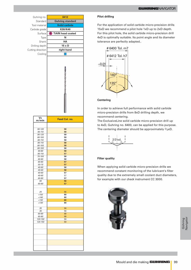
99
140°
135°
~0,01
# 6400 Tol. m7
# 6412 Tol. h7
2/3 xd1
90-120 5890-110 5890-120 5980-100 5980-110 5880-110 5880-100 5880-100 5860-80 5890-110 5770-100 5860-80 5860-80 5750-70 5740-60 5840-60 5840-60 5740-60 5760-80 57
60 5660-80 57
25 56<150 60<140 60<140 60<130 60
35 5635 56
60-80 6860-80 68
120-150 59120-150 59
Mould and die making
Gü
hri
ng
Nav
igat
or
Pilot drilling
For the application of solid carbide micro-precision drills 15xD we recommend a pilot hole 1xD up to 2xD depth. For this pilot hole, the solid carbide micro-precision drill 4xD is optimally suitable. Its point angle and its diameter tolerance are perfectly adapted..
Centering
In order to achieve full performance with solid carbide micro-precision drills from 8xD drilling depth, we recommend centering. The ExclusiveLine solid carbide micro-precision drill up to 4xD, Guhring no. 6400, can be applied for this purpose. The centering diameter should be approximately 2/3xD.
Filter quality
When applying solid carbide micro-precision drills we recommend constant monitoring of the lubricant‘s filter quality due to the extremely small coolant duct diameters,for example with our check instrument CC 3000.
Guhring no. 6412
Standard Guhring standard
Tool material Solid carbide
Carbide grade K30/K40
Surface TiAlN head coated
Type N
Shank HA
Drilling depth 15 x D
Cutting direction right-hand
Cooling
Vc m/min Feed Col. no.
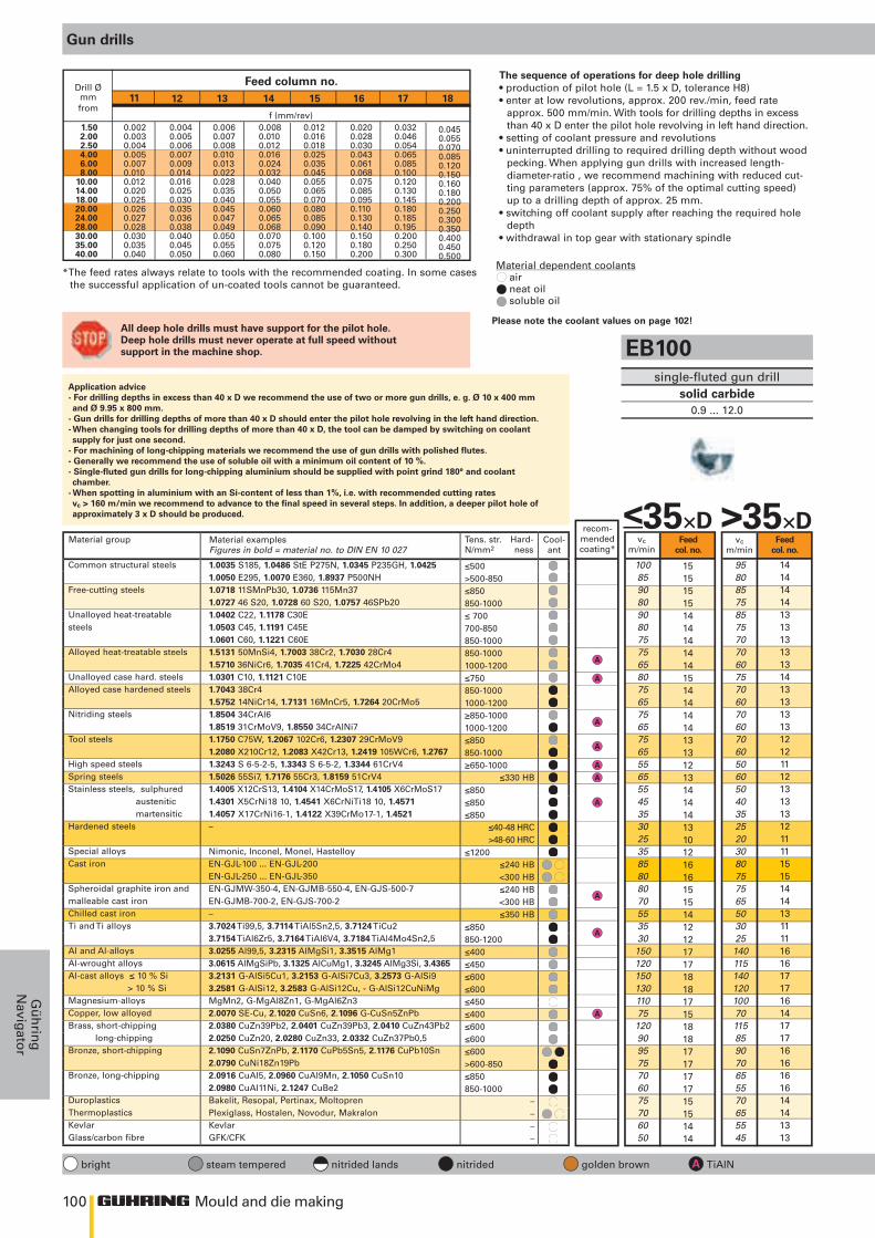
100
≤500>500-850≤850850-1000≤ 700700-850850-1000850-10001000-1200≤750850-10001000-1200≥850-10001000-1200≤850850-1000≥650-1000
≤850≤850≤850
≤1200
≤850 850-1200≤400≤450≤600≤600≤450≤400≤600≤600≤600>600-850≤850850-1000
≤330 HB
≤40-48 HRC>48-60 HRC
≤240 HB<300 HB≤240 HB<300 HB≤350 HB
––––
11 12 13 14 15 16 17 18
1515151514141414141514141414131312131414141310121616151514121217171818171518181717171715151414
1414141413131313131413131313121211121313131211111515141413111116161717161417171616161614141313
9580857585757070607570607060706050605040352520308075756550302514011514012010070115859070655570655545
>35×D
10085908090807575658075657565756555655545353025358580807055353015012015013011075120909575706075706050
<35×D
1818171716
18181817
181817171717
1515161615151515151515151515141414151414141312131616161615131216161717161517171717171716161515
1717161615
17171716
171716161616
1515161615151515151515151515141414151414141312131616161615131216161717161517171717171716161515
8075706560
115105130115
1251151051059090
8575807080757070607570656555605550604540352520208075706550302513512016513511070115859070655570655545
>35×D >35×D >35×D
8580757065
120110135120
1301201101109595
9080857585807575658075707060656055655045403025258580757055353014012517014011575120909575706075706050
<35×D <35×D <35×D
1414141413131313131413131313121211121313131211111515141413111116151616161417171616161614141313
1313131312121212121312121212111111121212121111111414131312111115141515151316161515151513131212
95808575857570706075706070607060506050403525203080757565503025
18020016012010070115859070655570655545
10085908090807575658075657565756555655545353025358580807055353018020016012011075120909575706075706050
TiAlN SuperA TiCN FIRE AlCrN TiN MolyGlide
Mould and die making
Gü
hrin
gN
avigator
Gun drills
*The feed rates always relate to tools with the recommended coating. In some cases the successful application of un-coated tools cannot be guaranteed.
Drill Ømmfrom
Feed column no.
f (mm/rev)0.0200.0280.0300.0430.0610.0680.0750.0850.0950.1100.1300.1400.1500.1800.200
1.502.002.504.006.008.00
10.0014.0018.0020.0024.0028.0030.0035.0040.00
0.0040.0050.0060.0070.0090.0140.0160.0250.0300.0350.0360.0380.0400.0450.050
0.0060.0070.0080.0100.0130.0220.0280.0350.0400.0450.0470.0490.0500.0550.060
0.0080.0100.0120.0160.0240.0320.0400.0500.0550.0600.0650.0680.0700.0750.080
0.0120.0160.0180.0250.0350.0450.0550.0650.0700.0800.0850.0900.1000.1200.150
0.0320.0460.0540.0650.0850.1000.1200.1300.1450.1800.1850.1950.2000.2500.300
0.0450.0550.0700.0850.1200.1500.1600.1800.2000.2500.3000.3500.4000.4500.500
0.0020.0030.0040.0050.0070.0100.0120.0200.0250.0260.0270.0280.0300.0350.040
Material group
Common structural steels
Free-cutting steels
Unalloyed heat-treatablesteels
Alloyed heat-treatable steels
Unalloyed case hard. steelsAlloyed case hardened steels
Nitriding steels
Tool steels
High speed steelsSpring steelsStainless steels, sulphured austenitic martensiticHardened steels
Special alloysCast iron
Spheroidal graphite iron andmalleable cast ironChilled cast ironTi and Ti alloys
Al and Al-alloysAl-wrought alloysAl-cast alloys ≤ 10 % Si > 10 % SiMagnesium-alloysCopper, low alloyedBrass, short-chipping long-chippingBronze, short-chipping
Bronze, long-chipping
DuroplasticsThermoplasticsKevlarGlass/carbon fibre
Material examplesFigures in bold = material no. to DIN EN 10 027
1.0035 S185, 1.0486 StE P275N, 1.0345 P235GH, 1.0425 1.0050 E295, 1.0070 E360, 1.8937 P500NH1.0718 11SMnPb30, 1.0736 115Mn371.0727 46 S20, 1.0728 60 S20, 1.0757 46SPb201.0402 C22, 1.1178 C30E1.0503 C45, 1.1191 C45E1.0601 C60, 1.1221 C60E1.5131 50MnSi4, 1.7003 38Cr2, 1.7030 28Cr41.5710 36NiCr6, 1.7035 41Cr4, 1.7225 42CrMo41.0301 C10, 1.1121 C10E1.7043 38Cr41.5752 14NiCr14, 1.7131 16MnCr5, 1.7264 20CrMo51.8504 34CrAl61.8519 31CrMoV9, 1.8550 34CrAlNi71.1750 C75W, 1.2067 102Cr6, 1.2307 29CrMoV91.2080 X210Cr12, 1.2083 X42Cr13, 1.2419 105WCr6, 1.27671.3243 S 6-5-2-5, 1.3343 S 6-5-2, 1.3344 61CrV41.5026 55Si7, 1.7176 55Cr3, 1.8159 51CrV41.4005 X12CrS13, 1.4104 X14CrMoS17, 1.4105 X6CrMoS171.4301 X5CrNi18 10, 1.4541 X6CrNiTi18 10, 1.45711.4057 X17CrNi16-1, 1.4122 X39CrMo17-1, 1.4521–
Nimonic, Inconel, Monel, HastelloyEN-GJL-100 ... EN-GJL-200EN-GJL-250 ... EN-GJL-350EN-GJMW-350-4, EN-GJMB-550-4, EN-GJS-500-7EN-GJMB-700-2, EN-GJS-700-2–3.7024 Ti99,5, 3.7114 TiAl5Sn2,5, 3.7124 TiCu23.7154 TiAl6Zr5, 3.7164 TiAl6V4, 3.7184 TiAl4Mo4Sn2,53.0255 Al99,5, 3.2315 AlMgSi1, 3.3515 AlMg13.0615 AlMgSiPb, 3.1325 AlCuMg1, 3.3245 AlMg3Si, 3.43653.2131 G-AlSi5Cu1, 3.2153 G-AlSi7Cu3, 3.2573 G-AlSi93.2581 G-AlSi12, 3.2583 G-AlSi12Cu, - G-AlSi12CuNiMgMgMn2, G-MgAl8Zn1, G-MgAl6Zn32.0070 SE-Cu, 2.1020 CuSn6, 2.1096 G-CuSn5ZnPb2.0380 CuZn39Pb2, 2.0401 CuZn39Pb3, 2.0410 CuZn43Pb22.0250 CuZn20, 2.0280 CuZn33, 2.0332 CuZn37Pb0,52.1090 CuSn7ZnPb, 2.1170 CuPb5Sn5, 2.1176 CuPb10Sn2.0790 CuNi18Zn19Pb2.0916 CuAl5, 2.0960 CuAl9Mn, 2.1050 CuSn102.0980 CuAl11Ni, 2.1247 CuBe2Bakelit, Resopal, Pertinax, MoltoprenPlexiglass, Hostalen, Novodur, MakralonKevlarGFK/CFK
Tens. str.N/mm2
Hard-ness
Cool-ant
recom-mended coating*
Feedcol. no.
Feedcol. no.
vc m/min
vc m/min
bright steam tempered nitrided lands nitrided golden brown TiAlN
EB100single-fluted gun drill
solid carbide0.9 ... 12.0
The sequence of operations for deep hole drilling• production of pilot hole (L = 1.5 x D, tolerance H8)• enter at low revolutions, approx. 200 rev./min, feed rate
approx. 500 mm/min. With tools for drilling depths in excess than 40 x D enter the pilot hole revolving in left hand direction.
• setting of coolant pressure and revolutions• uninterrupted drilling to required drilling depth without wood
pecking. When applying gun drills with increased length-diameter-ratio , we recommend machining with reduced cut-ting parameters (approx. 75% of the optimal cutting speed) up to a drilling depth of approx. 25 mm.
• switching off coolant supply after reaching the required hole depth
• withdrawal in top gear with stationary spindle
Application advice- For drilling depths in excess than 40 x D we recommend the use of two or more gun drills, e. g. Ø 10 x 400 mm and Ø 9.95 x 800 mm.
- Gun drills for drilling depths of more than 40 x D should enter the pilot hole revolving in the left hand direction.- When changing tools for drilling depths of more than 40 x D, the tool can be damped by switching on coolant supply for just one second.
- For machining of long-chipping materials we recommend the use of gun drills with polished flutes.- Generally we recommend the use of soluble oil with a minimum oil content of 10 %.- Single-fluted gun drills for long-chipping aluminium should be supplied with point grind 180° and coolant chamber.
- When spotting in aluminium with an Si-content of less than 1%, i.e. with recommended cutting rates vc > 160 m/min we recommend to advance to the final speed in several steps. In addition, a deeper pilot hole of approximately 3 x D should be produced.
Material dependent coolants air neat oil soluble oil
Please note Sie the coolant values on page 86/87!All deep hole drills must have support for the pilot hole. Deep hole drills must never operate at full speed without support in the machine shop.
recom-mended coating*
recom-mended coating*
recom-mended coating*
Feedcol. no.
Feedcol. no.
Feedcol. no.
Feedcol. no.
Feedcol. no.
Feedcol. no.
vc m/min
vc m/min
vc m/min
vc m/min
vc m/min
vc m/min
bright steam tempered nitrided lands nitrided golden brown TiAlN
EB80single-fluted gun drill
solid carbide head2.0 ... 40.0
ZB80two-fluted gun drillsolid carbide head
6.0 ... 27.0
EB800single-fluted gun drillwith indexable inserts
12.0 ... 40.0
Ratio end mill type RF 100 U, Guhring no. 3736Thanks to its unequal helix angle, Guhring’s FIRE-coated Ratio end mill RF 100 U offers highest feed rates and tool life for fi nishing and roughing operations in steel and cast materials as well as Ti- and Ni-alloys. Further information about the range can be found in Guhring’s current main catalogue.
Ratio drill RT 100 U, Guhring no. 2477Ratio drill RT 100 F, Guhring no. 1660Thanks to their special cutting edge geometry, Guhring’s Ratio drills excel with very good self-centering characteristics and alignment accurate ho-les. Type U is especially suitable for the machining of steel and high-allo-yed AlSi-alloys, type F for high-alloyed, stainless, acid- and heat-resistant steels, Al and Al-alloys, Mg and Mg-alloys as well as Ti and Ti-alloys.
ProcedureIn order to achieve optimal machining results when producing deep holes with type RT 100 T especially spotting on radii or on an uneven surface structure, we recommend the following machining steps:1. Initial milling of surface, i.e. with Guhring’s centre cutting Ratio end mill RF
100 U. The surface must be machined at right angles to the entry angle of the drilling operation.
2. Production of a cylindrical pilot hole (tolerance F9) with a minimum drilling depth of 1 x D. For this operation we recommend our Ratio drills RT 100 U or RT 100 F respectively. Thanks to a 140º point angle and a m7 tolerance on diameter these Ratio drills are especially suitable for this machining task.
3. Entry of spiral-fl ute deep hole drill RT 100 T in the pilot hole at a speed of ap-prox. 300 rev./min and with a feed rate of approx. 500 mm/min.
4. Setting of coolant pressure and speed.5. Continuous drilling to complete hole depth without wood pecking.6. For through holes with plain - i.e. 90° - exit, reduce feed rate vf to 50 % approx. 1 mm prior to break-through.7. For through holes with oblique exit, reduce the feed rate vf to 40% approx. 1
mm prior to break-through.8. After reaching hole depth stop machine spindle and coolant supply, with-
drawal in top gear.Please note the coolant values on page 102!
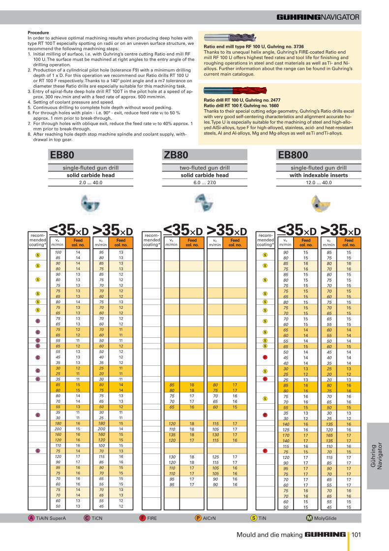
101
≤500>500-850≤850850-1000≤ 700700-850850-1000850-10001000-1200≤750850-10001000-1200≥850-10001000-1200≤850850-1000≥650-1000
≤850≤850≤850
≤1200
≤850 850-1200≤400≤450≤600≤600≤450≤400≤600≤600≤600>600-850≤850850-1000
≤330 HB
≤40-48 HRC>48-60 HRC
≤240 HB<300 HB≤240 HB<300 HB≤350 HB
––––
11 12 13 14 15 16 17 18
1515151514141414141514141414131312131414141310121616151514121217171818171518181717171715151414
1414141413131313131413131313121211121313131211111515141413111116161717161417171616161614141313
9580857585757070607570607060706050605040352520308075756550302514011514012010070115859070655570655545
>35×D
10085908090807575658075657565756555655545353025358580807055353015012015013011075120909575706075706050
<35×D
1818171716
18181817
181817171717
1515161615151515151515151515141414151414141312131616161615131216161717161517171717171716161515
1717161615
17171716
171716161616
1515161615151515151515151515141414151414141312131616161615131216161717161517171717171716161515
8075706560
115105130115
1251151051059090
8575807080757070607570656555605550604540352520208075706550302513512016513511070115859070655570655545
>35×D >35×D >35×D
8580757065
120110135120
1301201101109595
9080857585807575658075707060656055655045403025258580757055353014012517014011575120909575706075706050
<35×D <35×D <35×D
1414141413131313131413131313121211121313131211111515141413111116151616161417171616161614141313
1313131312121212121312121212111111121212121111111414131312111115141515151316161515151513131212
95808575857570706075706070607060506050403525203080757565503025
18020016012010070115859070655570655545
10085908090807575658075657565756555655545353025358580807055353018020016012011075120909575706075706050
TiAlN SuperA TiCN FIRE AlCrN TiN MolyGlide
Mould and die making
Gü
hri
ng
Nav
igat
or
Gun drills
*The feed rates always relate to tools with the recommended coating. In some cases the successful application of un-coated tools cannot be guaranteed.
Drill Ømmfrom
Feed column no.
f (mm/rev)0.0200.0280.0300.0430.0610.0680.0750.0850.0950.1100.1300.1400.1500.1800.200
1.502.002.504.006.008.00
10.0014.0018.0020.0024.0028.0030.0035.0040.00
0.0040.0050.0060.0070.0090.0140.0160.0250.0300.0350.0360.0380.0400.0450.050
0.0060.0070.0080.0100.0130.0220.0280.0350.0400.0450.0470.0490.0500.0550.060
0.0080.0100.0120.0160.0240.0320.0400.0500.0550.0600.0650.0680.0700.0750.080
0.0120.0160.0180.0250.0350.0450.0550.0650.0700.0800.0850.0900.1000.1200.150
0.0320.0460.0540.0650.0850.1000.1200.1300.1450.1800.1850.1950.2000.2500.300
0.0450.0550.0700.0850.1200.1500.1600.1800.2000.2500.3000.3500.4000.4500.500
0.0020.0030.0040.0050.0070.0100.0120.0200.0250.0260.0270.0280.0300.0350.040
Material group
Common structural steels
Free-cutting steels
Unalloyed heat-treatablesteels
Alloyed heat-treatable steels
Unalloyed case hard. steelsAlloyed case hardened steels
Nitriding steels
Tool steels
High speed steelsSpring steelsStainless steels, sulphured austenitic martensiticHardened steels
Special alloysCast iron
Spheroidal graphite iron andmalleable cast ironChilled cast ironTi and Ti alloys
Al and Al-alloysAl-wrought alloysAl-cast alloys ≤ 10 % Si > 10 % SiMagnesium-alloysCopper, low alloyedBrass, short-chipping long-chippingBronze, short-chipping
Bronze, long-chipping
DuroplasticsThermoplasticsKevlarGlass/carbon fibre
Material examplesFigures in bold = material no. to DIN EN 10 027
1.0035 S185, 1.0486 StE P275N, 1.0345 P235GH, 1.0425 1.0050 E295, 1.0070 E360, 1.8937 P500NH1.0718 11SMnPb30, 1.0736 115Mn371.0727 46 S20, 1.0728 60 S20, 1.0757 46SPb201.0402 C22, 1.1178 C30E1.0503 C45, 1.1191 C45E1.0601 C60, 1.1221 C60E1.5131 50MnSi4, 1.7003 38Cr2, 1.7030 28Cr41.5710 36NiCr6, 1.7035 41Cr4, 1.7225 42CrMo41.0301 C10, 1.1121 C10E1.7043 38Cr41.5752 14NiCr14, 1.7131 16MnCr5, 1.7264 20CrMo51.8504 34CrAl61.8519 31CrMoV9, 1.8550 34CrAlNi71.1750 C75W, 1.2067 102Cr6, 1.2307 29CrMoV91.2080 X210Cr12, 1.2083 X42Cr13, 1.2419 105WCr6, 1.27671.3243 S 6-5-2-5, 1.3343 S 6-5-2, 1.3344 61CrV41.5026 55Si7, 1.7176 55Cr3, 1.8159 51CrV41.4005 X12CrS13, 1.4104 X14CrMoS17, 1.4105 X6CrMoS171.4301 X5CrNi18 10, 1.4541 X6CrNiTi18 10, 1.45711.4057 X17CrNi16-1, 1.4122 X39CrMo17-1, 1.4521–
Nimonic, Inconel, Monel, HastelloyEN-GJL-100 ... EN-GJL-200EN-GJL-250 ... EN-GJL-350EN-GJMW-350-4, EN-GJMB-550-4, EN-GJS-500-7EN-GJMB-700-2, EN-GJS-700-2–3.7024 Ti99,5, 3.7114 TiAl5Sn2,5, 3.7124 TiCu23.7154 TiAl6Zr5, 3.7164 TiAl6V4, 3.7184 TiAl4Mo4Sn2,53.0255 Al99,5, 3.2315 AlMgSi1, 3.3515 AlMg13.0615 AlMgSiPb, 3.1325 AlCuMg1, 3.3245 AlMg3Si, 3.43653.2131 G-AlSi5Cu1, 3.2153 G-AlSi7Cu3, 3.2573 G-AlSi93.2581 G-AlSi12, 3.2583 G-AlSi12Cu, - G-AlSi12CuNiMgMgMn2, G-MgAl8Zn1, G-MgAl6Zn32.0070 SE-Cu, 2.1020 CuSn6, 2.1096 G-CuSn5ZnPb2.0380 CuZn39Pb2, 2.0401 CuZn39Pb3, 2.0410 CuZn43Pb22.0250 CuZn20, 2.0280 CuZn33, 2.0332 CuZn37Pb0,52.1090 CuSn7ZnPb, 2.1170 CuPb5Sn5, 2.1176 CuPb10Sn2.0790 CuNi18Zn19Pb2.0916 CuAl5, 2.0960 CuAl9Mn, 2.1050 CuSn102.0980 CuAl11Ni, 2.1247 CuBe2Bakelit, Resopal, Pertinax, MoltoprenPlexiglass, Hostalen, Novodur, MakralonKevlarGFK/CFK
Tens. str.N/mm2
Hard-ness
Cool-ant
recom-mended coating*
Feedcol. no.
Feedcol. no.
vc m/min
vc m/min
bright steam tempered nitrided lands nitrided golden brown TiAlN
EB100single-fluted gun drill
solid carbide0.9 ... 12.0
The sequence of operations for deep hole drilling• production of pilot hole (L = 1.5 x D, tolerance H8)• enter at low revolutions, approx. 200 rev./min, feed rate
approx. 500 mm/min. With tools for drilling depths in excess than 40 x D enter the pilot hole revolving in left hand direction.
• setting of coolant pressure and revolutions• uninterrupted drilling to required drilling depth without wood
pecking. When applying gun drills with increased length-diameter-ratio , we recommend machining with reduced cut-ting parameters (approx. 75% of the optimal cutting speed) up to a drilling depth of approx. 25 mm.
• switching off coolant supply after reaching the required hole depth
• withdrawal in top gear with stationary spindle
Application advice- For drilling depths in excess than 40 x D we recommend the use of two or more gun drills, e. g. Ø 10 x 400 mm and Ø 9.95 x 800 mm.
- Gun drills for drilling depths of more than 40 x D should enter the pilot hole revolving in the left hand direction.- When changing tools for drilling depths of more than 40 x D, the tool can be damped by switching on coolant supply for just one second.
- For machining of long-chipping materials we recommend the use of gun drills with polished flutes.- Generally we recommend the use of soluble oil with a minimum oil content of 10 %.- Single-fluted gun drills for long-chipping aluminium should be supplied with point grind 180° and coolant chamber.
- When spotting in aluminium with an Si-content of less than 1%, i.e. with recommended cutting rates vc > 160 m/min we recommend to advance to the final speed in several steps. In addition, a deeper pilot hole of approximately 3 x D should be produced.
Material dependent coolants air neat oil soluble oil
Please note Sie the coolant values on page 86/87!All deep hole drills must have support for the pilot hole. Deep hole drills must never operate at full speed without support in the machine shop.
recom-mended coating*
recom-mended coating*
recom-mended coating*
Feedcol. no.
Feedcol. no.
Feedcol. no.
Feedcol. no.
Feedcol. no.
Feedcol. no.
vc m/min
vc m/min
vc m/min
vc m/min
vc m/min
vc m/min
bright steam tempered nitrided lands nitrided golden brown TiAlN
EB80single-fluted gun drill
solid carbide head2.0 ... 40.0
ZB80two-fluted gun drillsolid carbide head
6.0 ... 27.0
EB800single-fluted gun drillwith indexable inserts
12.0 ... 40.0
Ratio end mill type RF 100 U, Guhring no. 3736Thanks to its unequal helix angle, Guhring’s FIRE-coated Ratio end mill RF 100 U offers highest feed rates and tool life for fi nishing and roughing operations in steel and cast materials as well as Ti- and Ni-alloys. Further information about the range can be found in Guhring’s current main catalogue.
Ratio drill RT 100 U, Guhring no. 2477Ratio drill RT 100 F, Guhring no. 1660Thanks to their special cutting edge geometry, Guhring’s Ratio drills excel with very good self-centering characteristics and alignment accurate ho-les. Type U is especially suitable for the machining of steel and high-allo-yed AlSi-alloys, type F for high-alloyed, stainless, acid- and heat-resistant steels, Al and Al-alloys, Mg and Mg-alloys as well as Ti and Ti-alloys.
ProcedureIn order to achieve optimal machining results when producing deep holes with type RT 100 T especially spotting on radii or on an uneven surface structure, we recommend the following machining steps:1. Initial milling of surface, i.e. with Guhring’s centre cutting Ratio end mill RF
100 U. The surface must be machined at right angles to the entry angle of the drilling operation.
2. Production of a cylindrical pilot hole (tolerance F9) with a minimum drilling depth of 1 x D. For this operation we recommend our Ratio drills RT 100 U or RT 100 F respectively. Thanks to a 140º point angle and a m7 tolerance on diameter these Ratio drills are especially suitable for this machining task.
3. Entry of spiral-fl ute deep hole drill RT 100 T in the pilot hole at a speed of ap-prox. 300 rev./min and with a feed rate of approx. 500 mm/min.
4. Setting of coolant pressure and speed.5. Continuous drilling to complete hole depth without wood pecking.6. For through holes with plain - i.e. 90° - exit, reduce feed rate vf to 50 % approx. 1 mm prior to break-through.7. For through holes with oblique exit, reduce the feed rate vf to 40% approx. 1
mm prior to break-through.8. After reaching hole depth stop machine spindle and coolant supply, with-
drawal in top gear.
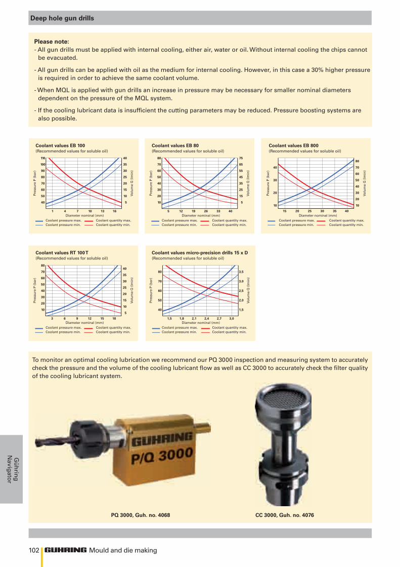
102
110 40
100 35
90 30
80 25
70 20
60 15
50 10
40 5
1 4 7 10 13 16
80 75
70 65
60 55
50 45
40 35
30 25
20 15
10 5
5 12 19 26 33 40
80
40 70
60
30 50
40
20 30
20
10 10
15 20 25 30 35 40
8040
7035
6030
5025
4020
3015
2010
105
3 6 9 12 15 18
80 3,5
70 3,0
60 2,5
50 2,0
40 1,5
1,5 1,8 2,1 2,4 2,7 3,0
Mould and die making
Gü
hrin
gN
avigator
Deep hole gun drills
Please note:- All gun drills must be applied with internal cooling, either air, water or oil. Without internal cooling the chips cannot
be evacuated.
- All gun drills can be applied with oil as the medium for internal cooling. However, in this case a 30% higher pressure is required in order to achieve the same coolant volume.
- When MQL is applied with gun drills an increase in pressure may be necessary for smaller nominal diameters dependent on the pressure of the MQL system.
- If the cooling lubricant data is insufficient the cutting parameters may be reduced. Pressure boosting systems are also possible.
To monitor an optimal cooling lubrication we recommend our PQ 3000 inspection and measuring system to accuratelycheck the pressure and the volume of the cooling lubricant flow as well as CC 3000 to accurately check the filter qualityof the cooling lubricant system.
CC 3000, Guh. no. 4076PQ 3000, Guh. no. 4068
Coolant values EB 100(Recommended values for soluble oil)
Coolant values RT 100 T(Recommended values for soluble oil)
Coolant values EB 80(Recommended values for soluble oil)
Coolant values micro-precision drills 15 x D(Recommended values for soluble oil)
Coolant values EB 800(Recommended values for soluble oil)
Diameter nominal (mm)Coolant pressure max. Coolant quantity max.Coolant pressure min. Coolant quantity min.
Diameter nominal (mm)Coolant pressure max. Coolant quantity max.Coolant pressure min. Coolant quantity min.
Diameter nominal (mm)Coolant pressure max. Coolant quantity max.Coolant pressure min. Coolant quantity min.
Diameter nominal (mm)Coolant pressure max. Coolant quantity max.Coolant pressure min. Coolant quantity min.
Diameter nominal (mm)Coolant pressure max. Coolant quantity max.Coolant pressure min. Coolant quantity min.
Pres
sure
P (
bar
)Pr
essu
re P
(b
ar)
Pres
sure
P (
bar
)Pr
essu
re P
(b
ar)
Pres
sure
P (
bar
)
Volu
me
Q (
lmin
)Vo
lum
e Q
(lm
in)
Volu
me
Q (
lmin
)Vo
lum
e Q
(lm
in)
Volu
me
Q (
lmin
)
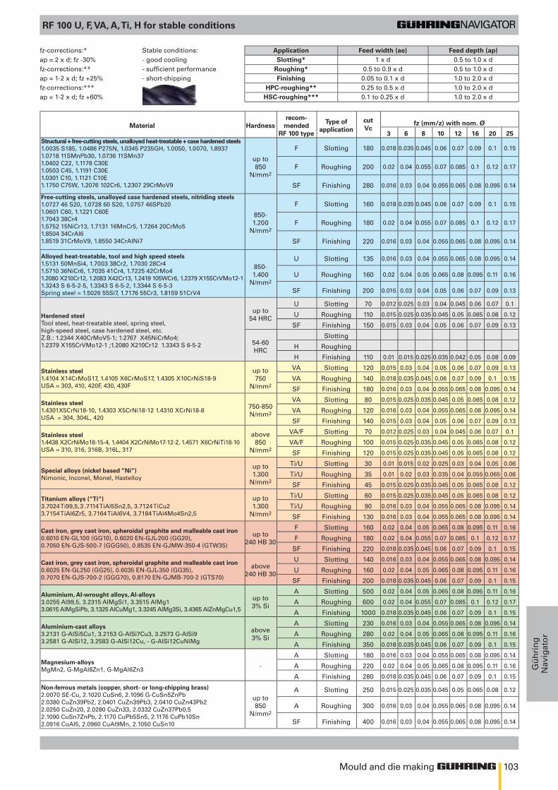
103Mould and die making
Gü
hri
ng
Nav
igat
or
RF 100 U, F, VA, A, Ti, H for stable conditions
Material Hardnessrecom-
mendedRF 100 type
Type ofapplication
cutVc
fz (mm/z) with nom. Ø
3 6 8 10 12 16 20 25Structural + free-cutting steels, unalloyed heat-treatable + case hardened steels1.0035 S185, 1.0486 P275N, 1.0345 P235GH, 1.0050, 1.0070, 1.89371.0718 11SMnPb30, 1.0736 11SMn371.0402 C22, 1.1178 C30E1.0503 C45, 1.1191 C30E1.0301 C10, 1.1121 C10E1.1750 C75W, 1.2076 102Cr6, 1.2307 29CrMoV9
up to850
N/mm2
F Slotting 180 0.018 0.035 0.045 0.06 0.07 0.09 0.1 0.15
F Roughing 200 0.02 0.04 0.055 0.07 0.085 0.1 0.12 0.17
SF Finishing 280 0.016 0.03 0.04 0.055 0.065 0.08 0.095 0.14
Free-cutting steels, unalloyed case hardened steels, nitriding steels1.0727 46 S20, 1.0728 60 S20, 1.0757 46SPb201.0601 C60, 1.1221 C60E1.7043 38Cr41.5752 15NiCr13, 1.7131 16MnCr5, 1.7264 20CrMo51.8504 34CrAl61.8519 31CrMoV9, 1.8550 34CrAlNi7
850-1.200
N/mm2
F Slotting 160 0.018 0.035 0.045 0.06 0.07 0.09 0.1 0.15
F Roughing 180 0.02 0.04 0.055 0.07 0.085 0.1 0.12 0.17
SF Finishing 220 0.016 0.03 0.04 0.055 0.065 0.08 0.095 0.14
Alloyed heat-treatable, tool and high speed steels1.5131 50MnSi4, 1.7003 38Cr2, 1.7030 28Cr41.5710 36NiCr6, 1.7035 41Cr4, 1.7225 42CrMo41.2080 X210Cr12, 1.2083 X42Cr13, 1.2419 105WCr6, 1.2379 X155CrVMo12-1 1.3243 S 6-5-2-5, 1.3343 S 6-5-2, 1.3344 S 6-5-3Spring steel = 1.5026 55Si7, 1.7176 55Cr3, 1.8159 51CrV4
850-1.400
N/mm2
U Slotting 135 0.016 0.03 0.04 0.055 0.065 0.08 0.095 0.14
U Roughing 160 0.02 0.04 0.05 0.065 0.08 0.095 0.11 0.16
SF Finishing 200 0.015 0.03 0.04 0.05 0.06 0.07 0.09 0.13
Hardened steelTool steel, heat-treatable steel, spring steel, high-speed steel, case hardened steel, etc. Z.B.: 1.2344 X40CrMoV5-1; 1.2767 X45NiCrMo4; 1.2379 X155CrVMo12-1 ;1.2080 X210Cr12 1.3343 S 6-5-2
up to54 HRC
U Slotting 70 0.012 0.025 0.03 0.04 0.045 0.06 0.07 0.1
U Roughing 110 0.015 0.025 0.035 0.045 0.05 0.065 0.08 0.12
SF Finishing 150 0.015 0.03 0.04 0.05 0.06 0.07 0.09 0.13
54-60 HRC
Slotting
H Roughing
H Finishing 110 0.01 0.015 0.025 0.035 0.042 0.05 0.08 0.09
Stainless steel1.4104 X14CrMoS17, 1.4105 X6CrMoS17, 1.4305 X10CrNiS18-9USA = 303, 410, 420F, 430, 430F
up to750
N/mm2
VA Slotting 120 0.015 0.03 0.04 0.05 0.06 0.07 0.09 0.13
VA Roughing 140 0.018 0.035 0.045 0.06 0.07 0.09 0.1 0.15
SF Finishing 180 0.016 0.03 0.04 0.055 0.065 0.08 0.095 0.14
Stainless steel1.4301X5CrNi18-10, 1.4303 X5CrNi18-12 1.4310 XCrNi18-8USA = 304, 304L, 420
750-850 N/mm2
VA Slotting 80 0.015 0.025 0.035 0.045 0.05 0.065 0.08 0.12
VA Roughing 120 0.016 0.03 0.04 0.055 0.065 0.08 0.095 0.14
SF Finishing 140 0.015 0.03 0.04 0.05 0.06 0.07 0.09 0.13
Stainless steel1.4438 X2CrNiMo18-15-4, 1.4404 X2CrNiMo17-12-2, 1.4571 X6CrNiTi18-10USA = 310, 316, 316B, 316L, 317
above850
N/mm2
VA/F Slotting 70 0.012 0.025 0.03 0.04 0.045 0.06 0.07 0.1
VA/F Roughing 100 0.015 0.025 0.035 0.045 0.05 0.065 0.08 0.12
SF Finishing 120 0.015 0.025 0.035 0.045 0.05 0.065 0.08 0.12
Special alloys (nickel based “Ni“)Nimonic, Inconel, Monel, Hastelloy
up to1.300
N/mm2
Ti/U Slotting 30 0.01 0.015 0.02 0.025 0.03 0.04 0.05 0.06
Ti/U Roughing 35 0.01 0.02 0.03 0.035 0.04 0.055 0.065 0.08
SF Finishing 45 0.015 0.025 0.035 0.045 0.05 0.065 0.08 0.12
Titanium alloys (“Ti“)3.7024 Ti99,5, 3 .7114 TiAl5Sn2,5, 3.7124 TiCu23.7154 TiAl6Zr5, 3.7164 TiAl6V4, 3.7184 TiAl4Mo4Sn2,5
up to1.300
N/mm2
Ti/U Slotting 60 0.015 0.025 0.035 0.045 0.05 0.065 0.08 0.12
Ti/U Roughing 90 0.016 0.03 0.04 0.055 0.065 0.08 0.095 0.14
SF Finishing 130 0.016 0.03 0.04 0.055 0.065 0.08 0.095 0.14
Cast iron, grey cast iron, spheroidal graphite and malleable cast iron0.6010 EN-GL100 (GG10), 0.6020 EN-GJL-200 (GG20), 0.7050 EN-GJS-500-7 (GGG50), 0.8535 EN-GJMW-350-4 (GTW35)
up to240 HB 30
F Slotting 160 0.02 0.04 0.05 0.065 0.08 0.095 0.11 0.16
F Roughing 180 0.02 0.04 0.055 0.07 0.085 0.1 0.12 0.17
SF Finishing 220 0.018 0.035 0.045 0.06 0.07 0.09 0.1 0.15
Cast iron, grey cast iron, spheroidal graphite and malleable cast iron0.6025 EN-GL250 (GG25), 0.6035 EN-GJL-350 (GG35), 0.7070 EN-GJS-700-2 (GGG70), 0.8170 EN-GJMB-700-2 (GTS70)
above240 HB 30
U Slotting 140 0.016 0.03 0.04 0.055 0.065 0.08 0.095 0.14
U Roughing 160 0.02 0.04 0.05 0.065 0.08 0.095 0.11 0.16
SF Finishing 200 0.018 0.035 0.045 0.06 0.07 0.09 0.1 0.15
Aluminium, Al-wrought alloys, Al-alloys3.0255 Al99,5, 3.2315 AlMgSi1, 3.3515 AlMg13.0615 AlMgSiPb, 3.1325 AlCuMg1, 3.3245 AlMg3Si, 3.4365 AlZnMgCu1,5
up to3% Si
A Slotting 500 0.02 0.04 0.05 0.065 0.08 0.095 0.11 0.16
A Roughing 600 0.02 0.04 0.055 0.07 0.085 0.1 0.12 0.17
A Finishing 1000 0.018 0.035 0.045 0.06 0.07 0.09 0.1 0.15
Aluminium-cast alloys3.2131 G-AlSi5Cu1, 3.2153 G-AlSi7Cu3, 3.2573 G-AlSi93.2581 G-AlSi12, 3.2583 G-AlSi12Cu, - G-AlSi12CuNiMg
above3% Si
A Slotting 230 0.016 0.03 0.04 0.055 0.065 0.08 0.095 0.14
A Roughing 280 0.02 0.04 0.05 0.065 0.08 0.095 0.11 0.16
A Finishing 350 0.018 0.035 0.045 0.06 0.07 0.09 0.1 0.15
Magnesium-alloysMgMn2, G-MgAl8Zn1, G-MgAl6Zn3 -
A Slotting 180 0.016 0.03 0.04 0.055 0.065 0.08 0.095 0.14
A Roughing 220 0.02 0.04 0.05 0.065 0.08 0.095 0.11 0.16
A Finishing 280 0.018 0.035 0.045 0.06 0.07 0.09 0.1 0.15
Non-ferrous metals (copper, short- or long-chipping brass)2.0070 SE-Cu, 2.1020 CuSn6, 2.1096 G-CuSn5ZnPb2.0380 CuZn39Pb2, 2.0401 CuZn39Pb3, 2.0410 CuZn43Pb22.0250 CuZn20, 2.0280 CuZn33, 2.0332 CuZn37Pb0,52.1090 CuSn7ZnPb, 2.1170 CuPb5Sn5, 2.1176 CuPb10Sn2.0916 CuAl5, 2.0960 CuAl9Mn, 2.1050 CuSn10
up to850
N/mm2
A Slotting 250 0.015 0.025 0.035 0.045 0.05 0.065 0.08 0.12
A Roughing 300 0.016 0.03 0.04 0.055 0.065 0.08 0.095 0.14
SF Finishing 400 0.016 0.03 0.04 0.055 0.065 0.08 0.095 0.14
fz-corrections:* Stable conditions: Application Feed width (ae) Feed depth (ap)ap = 2 x d; fz -30% - good cooling Slotting* 1 x d 0.5 to 1.0 x dfz-corrections:** - sufficient performance Roughing* 0.5 to 0.9 x d 0.5 to 1.0 x dap = 1-2 x d; fz +25% - short-chipping Finishing 0.05 to 0.1 x d 1.0 to 2.0 x dfz-corrections:*** HPC-roughing** 0.25 to 0.5 x d 1.0 to 2.0 x dap = 1-2 x d; fz +60% HSC-roughing*** 0.1 to 0.25 x d 1.0 to 2.0 x d
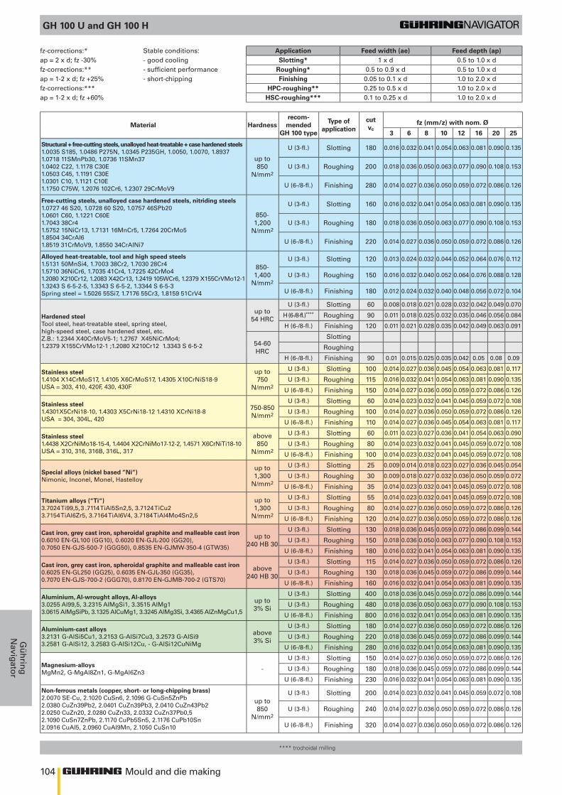
104 Mould and die making
Gü
hrin
gN
avigator
GH 100 U and GH 100 H
Material Hardnessrecom-
mendedGH 100 type
Type ofapplication
cutvc
fz (mm/z) with nom. Ø
3 6 8 10 12 16 20 25
Structural + free-cutting steels, unalloyed heat-treatable + case hardened steels1.0035 S185, 1.0486 P275N, 1.0345 P235GH, 1.0050, 1.0070, 1.89371.0718 11SMnPb30, 1.0736 11SMn371.0402 C22, 1.1178 C30E1.0503 C45, 1.1191 C30E1.0301 C10, 1.1121 C10E1.1750 C75W, 1.2076 102Cr6, 1.2307 29CrMoV9
up to850
N/mm2
U (3-fl.) Slotting 180 0.016 0.032 0.041 0.054 0.063 0.081 0.090 0.135
U (3-fl.) Roughing 200 0.018 0.036 0.050 0.063 0.077 0.090 0.108 0.153
U (6-/8-fl.) Finishing 280 0.014 0.027 0.036 0.050 0.059 0.072 0.086 0.126
Free-cutting steels, unalloyed case hardened steels, nitriding steels1.0727 46 S20, 1.0728 60 S20, 1.0757 46SPb201.0601 C60, 1.1221 C60E1.7043 38Cr41.5752 15NiCr13, 1.7131 16MnCr5, 1.7264 20CrMo51.8504 34CrAl61.8519 31CrMoV9, 1.8550 34CrAlNi7
850-1,200
N/mm2
U (3-fl.) Slotting 160 0.016 0.032 0.041 0.054 0.063 0.081 0.090 0.135
U (3-fl.) Roughing 180 0.018 0.036 0.050 0.063 0.077 0.090 0.108 0.153
U (6-/8-fl.) Finishing 220 0.014 0.027 0.036 0.050 0.059 0.072 0.086 0.126
Alloyed heat-treatable, tool and high speed steels1.5131 50MnSi4, 1.7003 38Cr2, 1.7030 28Cr41.5710 36NiCr6, 1.7035 41Cr4, 1.7225 42CrMo41.2080 X210Cr12, 1.2083 X42Cr13, 1.2419 105WCr6, 1.2379 X155CrVMo12-1 1.3243 S 6-5-2-5, 1.3343 S 6-5-2, 1.3344 S 6-5-3Spring steel = 1.5026 55Si7, 1.7176 55Cr3, 1.8159 51CrV4
850-1,400
N/mm2
U (3-fl.) Slotting 120 0.013 0.024 0.032 0.044 0.052 0.064 0.076 0.112
U (3-fl.) Roughing 150 0.016 0.032 0.040 0.052 0.064 0.076 0.088 0.128
U (6-/8-fl.) Finishing 180 0.012 0.024 0.032 0.040 0.048 0.056 0.072 0.104
Hardened steelTool steel, heat-treatable steel, spring steel, high-speed steel, case hardened steel, etc. Z.B.: 1.2344 X40CrMoV5-1; 1.2767 X45NiCrMo4; 1.2379 X155CrVMo12-1 ;1.2080 X210Cr12 1.3343 S 6-5-2
up to54 HRC
U (3-fl.) Slotting 60 0.008 0.018 0.021 0.028 0.032 0.042 0.049 0.070
H (6-/8-fl.)**** Roughing 90 0.011 0.018 0.025 0.032 0.035 0.046 0.056 0.084
H (6-/8-fl.) Finishing 120 0.011 0.021 0.028 0.035 0.042 0.049 0.063 0.091
54-60 HRC
Slotting
Roughing
H (6-/8-fl.) Finishing 90 0.01 0.015 0.025 0.035 0.042 0.05 0.08 0.09
Stainless steel1.4104 X14CrMoS17, 1.4105 X6CrMoS17, 1.4305 X10CrNiS18-9USA = 303, 410, 420F, 430, 430F
up to750
N/mm2
U (3-fl.) Slotting 100 0.014 0.027 0.036 0.045 0.054 0.063 0.081 0.117
U (3-fl.) Roughing 115 0.016 0.032 0.041 0.054 0.063 0.081 0.090 0.135
U (6-/8-fl.) Finishing 150 0.014 0.027 0.036 0.050 0.059 0.072 0.086 0.126
Stainless steel1.4301X5CrNi18-10, 1.4303 X5CrNi18-12 1.4310 XCrNi18-8USA = 304, 304L, 420
750-850 N/mm2
U (3-fl.) Slotting 60 0.014 0.023 0.032 0.041 0.045 0.059 0.072 0.108
U (3-fl.) Roughing 100 0.014 0.027 0.036 0.050 0.059 0.072 0.086 0.126
U (6-/8-fl.) Finishing 110 0.014 0.027 0.036 0.045 0.054 0.063 0.081 0.117
Stainless steel1.4438 X2CrNiMo18-15-4, 1.4404 X2CrNiMo17-12-2, 1.4571 X6CrNiTi18-10USA = 310, 316, 316B, 316L, 317
above850
N/mm2
U (3-fl.) Slotting 60 0.011 0.023 0.027 0.036 0.041 0.054 0.063 0.090
U (3-fl.) Roughing 80 0.014 0.023 0.032 0.041 0.045 0.059 0.072 0.108
U (6-/8-fl.) Finishing 100 0.014 0.023 0.032 0.041 0.045 0.059 0.072 0.108
Special alloys (nickel based “Ni“)Nimonic, Inconel, Monel, Hastelloy
up to1,300
N/mm2
U (3-fl.) Slotting 25 0.009 0.014 0.018 0.023 0.027 0.036 0.045 0.054
U (3-fl.) Roughing 30 0.009 0.018 0.027 0.032 0.036 0.050 0.059 0.072
U (6-/8-fl.) Finishing 35 0.014 0.023 0.032 0.041 0.045 0.059 0.072 0.108
Titanium alloys (“Ti“)3.7024 Ti99,5, 3 .7114 TiAl5Sn2,5, 3.7124 TiCu23.7154 TiAl6Zr5, 3.7164 TiAl6V4, 3.7184 TiAl4Mo4Sn2,5
up to1,300
N/mm2
U (3-fl.) Slotting 55 0.014 0.023 0.032 0.041 0.045 0.059 0.072 0.108
U (3-fl.) Roughing 80 0.014 0.027 0.036 0.050 0.059 0.072 0.086 0.126
U (6-/8-fl.) Finishing 120 0.014 0.027 0.036 0.050 0.059 0.072 0.086 0.126
Cast iron, grey cast iron, spheroidal graphite and malleable cast iron0.6010 EN-GL100 (GG10), 0.6020 EN-GJL-200 (GG20), 0.7050 EN-GJS-500-7 (GGG50), 0.8535 EN-GJMW-350-4 (GTW35)
up to240 HB 30
U (3-fl.) Slotting 130 0.018 0.036 0.045 0.059 0.072 0.086 0.099 0.144
U (3-fl.) Roughing 150 0.018 0.036 0.050 0.063 0.077 0.090 0.108 0.153
U (6-/8-fl.) Finishing 180 0.016 0.032 0.041 0.054 0.063 0.081 0.090 0.135
Cast iron, grey cast iron, spheroidal graphite and malleable cast iron0.6025 EN-GL250 (GG25), 0.6035 EN-GJL-350 (GG35), 0.7070 EN-GJS-700-2 (GGG70), 0.8170 EN-GJMB-700-2 (GTS70)
above240 HB 30
U (3-fl.) Slotting 115 0.014 0.027 0.036 0.050 0.059 0.072 0.086 0.126
U (3-fl.) Roughing 130 0.018 0.036 0.045 0.059 0.072 0.086 0.099 0.144
U (6-/8-fl.) Finishing 160 0.016 0.032 0.041 0.054 0.063 0.081 0.090 0.135
Aluminium, Al-wrought alloys, Al-alloys3.0255 Al99,5, 3.2315 AlMgSi1, 3.3515 AlMg13.0615 AlMgSiPb, 3.1325 AlCuMg1, 3.3245 AlMg3Si, 3.4365 AlZnMgCu1,5
up to3% Si
U (3-fl.) Slotting 400 0.018 0.036 0.045 0.059 0.072 0.086 0.099 0.144
U (3-fl.) Roughing 480 0.018 0.036 0.050 0.063 0.077 0.090 0.108 0.153
U (6-/8-fl.) Finishing 800 0.016 0.032 0.041 0.054 0.063 0.081 0.090 0.135
Aluminium-cast alloys3.2131 G-AlSi5Cu1, 3.2153 G-AlSi7Cu3, 3.2573 G-AlSi93.2581 G-AlSi12, 3.2583 G-AlSi12Cu, - G-AlSi12CuNiMg
above3% Si
U (3-fl.) Slotting 180 0.014 0.027 0.036 0.050 0.059 0.072 0.086 0.126
U (3-fl.) Roughing 220 0.018 0.036 0.045 0.059 0.072 0.086 0.099 0.144
U (6-/8-fl.) Finishing 280 0.016 0.032 0.041 0.054 0.063 0.081 0.090 0.135
Magnesium-alloysMgMn2, G-MgAl8Zn1, G-MgAl6Zn3 -
U (3-fl.) Slotting 150 0.014 0.027 0.036 0.050 0.059 0.072 0.086 0.126
U (3-fl.) Roughing 180 0.018 0.036 0.045 0.059 0.072 0.086 0.099 0.144
U (6-/8-fl.) Finishing 230 0.016 0.032 0.041 0.054 0.063 0.081 0.090 0.135
Non-ferrous metals (copper, short- or long-chipping brass)2.0070 SE-Cu, 2.1020 CuSn6, 2.1096 G-CuSn5ZnPb2.0380 CuZn39Pb2, 2.0401 CuZn39Pb3, 2.0410 CuZn43Pb22.0250 CuZn20, 2.0280 CuZn33, 2.0332 CuZn37Pb0,52.1090 CuSn7ZnPb, 2.1170 CuPb5Sn5, 2.1176 CuPb10Sn2.0916 CuAl5, 2.0960 CuAl9Mn, 2.1050 CuSn10
up to850
N/mm2
U (3-fl.) Slotting 200 0.014 0.023 0.032 0.041 0.045 0.059 0.072 0.108
U (3-fl.) Roughing 240 0.014 0.027 0.036 0.050 0.059 0.072 0.086 0.126
U (6-/8-fl.) Finishing 320 0.014 0.027 0.036 0.050 0.059 0.072 0.086 0.126
fz-corrections:* Stable conditions: Application Feed width (ae) Feed depth (ap)ap = 2 x d; fz -30% - good cooling Slotting* 1 x d 0.5 to 1.0 x dfz-corrections:** - sufficient performance Roughing* 0.5 to 0.9 x d 0.5 to 1.0 x dap = 1-2 x d; fz +25% - short-chipping Finishing 0.05 to 0.1 x d 1.0 to 2.0 x dfz-corrections:*** HPC-roughing** 0.25 to 0.5 x d 1.0 to 2.0 x dap = 1-2 x d; fz +60% HSC-roughing*** 0.1 to 0.25 x d 1.0 to 2.0 x d
**** trochoidal milling
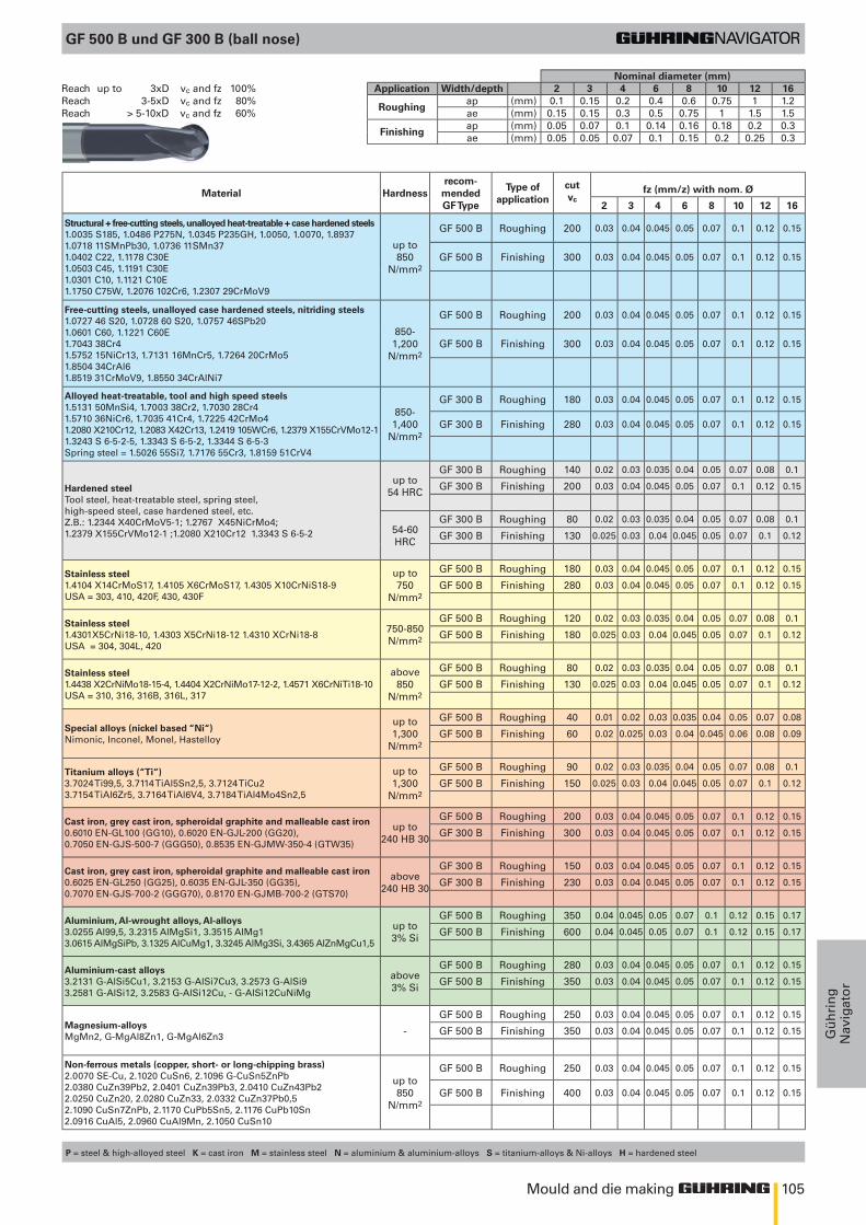
105Mould and die making
Gü
hri
ng
Nav
igat
or
GF 500 B und GF 300 B (ball nose)
Material Hardnessrecom-
mendedGF Type
Type ofapplication
cutvc
fz (mm/z) with nom. Ø
2 3 4 6 8 10 12 16
Structural + free-cutting steels, unalloyed heat-treatable + case hardened steels1.0035 S185, 1.0486 P275N, 1.0345 P235GH, 1.0050, 1.0070, 1.89371.0718 11SMnPb30, 1.0736 11SMn371.0402 C22, 1.1178 C30E1.0503 C45, 1.1191 C30E1.0301 C10, 1.1121 C10E1.1750 C75W, 1.2076 102Cr6, 1.2307 29CrMoV9
up to850
N/mm2
GF 500 B Roughing 200 0.03 0.04 0.045 0.05 0.07 0.1 0.12 0.15
GF 500 B Finishing 300 0.03 0.04 0.045 0.05 0.07 0.1 0.12 0.15
Free-cutting steels, unalloyed case hardened steels, nitriding steels1.0727 46 S20, 1.0728 60 S20, 1.0757 46SPb201.0601 C60, 1.1221 C60E1.7043 38Cr41.5752 15NiCr13, 1.7131 16MnCr5, 1.7264 20CrMo51.8504 34CrAl61.8519 31CrMoV9, 1.8550 34CrAlNi7
850-1,200
N/mm2
GF 500 B Roughing 200 0.03 0.04 0.045 0.05 0.07 0.1 0.12 0.15
GF 500 B Finishing 300 0.03 0.04 0.045 0.05 0.07 0.1 0.12 0.15
Alloyed heat-treatable, tool and high speed steels1.5131 50MnSi4, 1.7003 38Cr2, 1.7030 28Cr41.5710 36NiCr6, 1.7035 41Cr4, 1.7225 42CrMo41.2080 X210Cr12, 1.2083 X42Cr13, 1.2419 105WCr6, 1.2379 X155CrVMo12-1 1.3243 S 6-5-2-5, 1.3343 S 6-5-2, 1.3344 S 6-5-3Spring steel = 1.5026 55Si7, 1.7176 55Cr3, 1.8159 51CrV4
850-1,400
N/mm2
GF 300 B Roughing 180 0.03 0.04 0.045 0.05 0.07 0.1 0.12 0.15
GF 300 B Finishing 280 0.03 0.04 0.045 0.05 0.07 0.1 0.12 0.15
Hardened steelTool steel, heat-treatable steel, spring steel, high-speed steel, case hardened steel, etc. Z.B.: 1.2344 X40CrMoV5-1; 1.2767 X45NiCrMo4; 1.2379 X155CrVMo12-1 ;1.2080 X210Cr12 1.3343 S 6-5-2
up to54 HRC
GF 300 B Roughing 140 0.02 0.03 0.035 0.04 0.05 0.07 0.08 0.1
GF 300 B Finishing 200 0.03 0.04 0.045 0.05 0.07 0.1 0.12 0.15
54-60 HRC
GF 300 B Roughing 80 0.02 0.03 0.035 0.04 0.05 0.07 0.08 0.1
GF 300 B Finishing 130 0.025 0.03 0.04 0.045 0.05 0.07 0.1 0.12
Stainless steel1.4104 X14CrMoS17, 1.4105 X6CrMoS17, 1.4305 X10CrNiS18-9USA = 303, 410, 420F, 430, 430F
up to750
N/mm2
GF 500 B Roughing 180 0.03 0.04 0.045 0.05 0.07 0.1 0.12 0.15
GF 500 B Finishing 280 0.03 0.04 0.045 0.05 0.07 0.1 0.12 0.15
Stainless steel1.4301X5CrNi18-10, 1.4303 X5CrNi18-12 1.4310 XCrNi18-8USA = 304, 304L, 420
750-850 N/mm2
GF 500 B Roughing 120 0.02 0.03 0.035 0.04 0.05 0.07 0.08 0.1
GF 500 B Finishing 180 0.025 0.03 0.04 0.045 0.05 0.07 0.1 0.12
Stainless steel1.4438 X2CrNiMo18-15-4, 1.4404 X2CrNiMo17-12-2, 1.4571 X6CrNiTi18-10USA = 310, 316, 316B, 316L, 317
above850
N/mm2
GF 500 B Roughing 80 0.02 0.03 0.035 0.04 0.05 0.07 0.08 0.1
GF 500 B Finishing 130 0.025 0.03 0.04 0.045 0.05 0.07 0.1 0.12
Special alloys (nickel based “Ni“)Nimonic, Inconel, Monel, Hastelloy
up to1,300
N/mm2
GF 500 B Roughing 40 0.01 0.02 0.03 0.035 0.04 0.05 0.07 0.08
GF 500 B Finishing 60 0.02 0.025 0.03 0.04 0.045 0.06 0.08 0.09
Titanium alloys (“Ti“)3.7024 Ti99,5, 3.7114 TiAl5Sn2,5, 3.7124 TiCu23.7154 TiAl6Zr5, 3.7164 TiAl6V4, 3.7184 TiAl4Mo4Sn2,5
up to1,300
N/mm2
GF 500 B Roughing 90 0.02 0.03 0.035 0.04 0.05 0.07 0.08 0.1
GF 500 B Finishing 150 0.025 0.03 0.04 0.045 0.05 0.07 0.1 0.12
Cast iron, grey cast iron, spheroidal graphite and malleable cast iron0.6010 EN-GL100 (GG10), 0.6020 EN-GJL-200 (GG20), 0.7050 EN-GJS-500-7 (GGG50), 0.8535 EN-GJMW-350-4 (GTW35)
up to240 HB 30
GF 500 B Roughing 200 0.03 0.04 0.045 0.05 0.07 0.1 0.12 0.15
GF 300 B Finishing 300 0.03 0.04 0.045 0.05 0.07 0.1 0.12 0.15
Cast iron, grey cast iron, spheroidal graphite and malleable cast iron0.6025 EN-GL250 (GG25), 0.6035 EN-GJL-350 (GG35), 0.7070 EN-GJS-700-2 (GGG70), 0.8170 EN-GJMB-700-2 (GTS70)
above240 HB 30
GF 300 B Roughing 150 0.03 0.04 0.045 0.05 0.07 0.1 0.12 0.15
GF 300 B Finishing 230 0.03 0.04 0.045 0.05 0.07 0.1 0.12 0.15
Aluminium, Al-wrought alloys, Al-alloys3.0255 Al99,5, 3.2315 AlMgSi1, 3.3515 AlMg13.0615 AlMgSiPb, 3.1325 AlCuMg1, 3.3245 AlMg3Si, 3.4365 AlZnMgCu1,5
up to3% Si
GF 500 B Roughing 350 0.04 0.045 0.05 0.07 0.1 0.12 0.15 0.17
GF 500 B Finishing 600 0.04 0.045 0.05 0.07 0.1 0.12 0.15 0.17
Aluminium-cast alloys3.2131 G-AlSi5Cu1, 3.2153 G-AlSi7Cu3, 3.2573 G-AlSi93.2581 G-AlSi12, 3.2583 G-AlSi12Cu, - G-AlSi12CuNiMg
above3% Si
GF 500 B Roughing 280 0.03 0.04 0.045 0.05 0.07 0.1 0.12 0.15
GF 500 B Finishing 350 0.03 0.04 0.045 0.05 0.07 0.1 0.12 0.15
Magnesium-alloysMgMn2, G-MgAl8Zn1, G-MgAl6Zn3 -
GF 500 B Roughing 250 0.03 0.04 0.045 0.05 0.07 0.1 0.12 0.15
GF 500 B Finishing 350 0.03 0.04 0.045 0.05 0.07 0.1 0.12 0.15
Non-ferrous metals (copper, short- or long-chipping brass)2.0070 SE-Cu, 2.1020 CuSn6, 2.1096 G-CuSn5ZnPb2.0380 CuZn39Pb2, 2.0401 CuZn39Pb3, 2.0410 CuZn43Pb22.0250 CuZn20, 2.0280 CuZn33, 2.0332 CuZn37Pb0,52.1090 CuSn7ZnPb, 2.1170 CuPb5Sn5, 2.1176 CuPb10Sn2.0916 CuAl5, 2.0960 CuAl9Mn, 2.1050 CuSn10
up to850
N/mm2
GF 500 B Roughing 250 0.03 0.04 0.045 0.05 0.07 0.1 0.12 0.15
GF 500 B Finishing 400 0.03 0.04 0.045 0.05 0.07 0.1 0.12 0.15
Nominal diameter (mm)Reach up to 3xD vc and fz 100% Application Width/depth 2 3 4 6 8 10 12 16Reach 3-5xD vc and fz 80%
Roughingap (mm) 0.1 0.15 0.2 0.4 0.6 0.75 1 1.2
Reach > 5-10xD vc and fz 60% ae (mm) 0.15 0.15 0.3 0.5 0.75 1 1.5 1.5
Finishingap (mm) 0.05 0.07 0.1 0.14 0.16 0.18 0.2 0.3ae (mm) 0.05 0.05 0.07 0.1 0.15 0.2 0.25 0.3
P = steel & high-alloyed steel K = cast iron M = stainless steel N = aluminium & aluminium-alloys S = titanium-alloys & Ni-alloys H = hardened steel
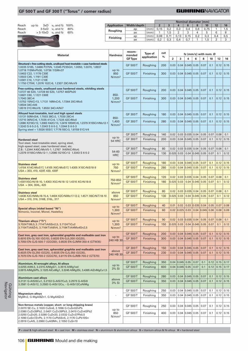
106 Mould and die making
Gü
hrin
gN
avigator
P = steel & high-alloyed steel K = cast iron M = stainless steel N = aluminium & aluminium alloys S = titanium-alloys & Ni-alloys H = hardened steel
GF 500 T and GF 300 T (“Torus“ / corner radius)
Material Hardnessrecom-
mendedGF Type
Type ofapplication
cutvc
fz (mm/z) with nom. Ø
2 3 4 6 8 10 12 16
Structural + free-cutting steels, unalloyed heat-treatable + case hardened steels1.0035 S185, 1.0486 P275N, 1.0345 P235GH, 1.0050, 1.0070, 1.89371.0718 11SMnPb30, 1.0736 11SMn371.0402 C22, 1.1178 C30E1.0503 C45, 1.1191 C30E1.0301 C10, 1.1121 C10E1.1750 C75W, 1.2076 102Cr6, 1.2307 29CrMoV9
up to850
N/mm2
GF 500 T Roughing 200 0.03 0.04 0.045 0.05 0.07 0.1 0.12 0.15
GF 500 T Finishing 300 0.03 0.04 0.045 0.05 0.07 0.1 0.12 0.15
Free-cutting steels, unalloyed case hardened steels, nitriding steels1.0727 46 S20, 1.0728 60 S20, 1.0757 46SPb201.0601 C60, 1.1221 C60E1.7043 38Cr41.5752 15NiCr13, 1.7131 16MnCr5, 1.7264 20CrMo51.8504 34CrAl61.8519 31CrMoV9, 1.8550 34CrAlNi7
850-1,200
N/mm2
GF 500 T Roughing 200 0.03 0.04 0.045 0.05 0.07 0.1 0.12 0.15
GF 500 T Finishing 300 0.03 0.04 0.045 0.05 0.07 0.1 0.12 0.15
Alloyed heat-treatable, tool and high speed steels1.5131 50MnSi4, 1.7003 38Cr2, 1.7030 28Cr41.5710 36NiCr6, 1.7035 41Cr4, 1.7225 42CrMo41.2080 X210Cr12, 1.2083 X42Cr13, 1.2419 105WCr6, 1.2379 X155CrVMo12-1 1.3243 S 6-5-2-5, 1.3343 S 6-5-2, 1.3344 S 6-5-3Spring steel = 1.5026 55Si7, 1.7176 55Cr3, 1.8159 51CrV4
850-1,400
N/mm2
GF 300 T Roughing 180 0.03 0.04 0.045 0.05 0.07 0.1 0.12 0.15
GF 300 T Finishing 280 0.03 0.04 0.045 0.05 0.07 0.1 0.12 0.15
Hardened steelTool steel, heat-treatable steel, spring steel, high-speed steel, case hardened steel, etc. Z.B.: 1.2344 X40CrMoV5-1; 1.2767 X45NiCrMo4; 1.2379 X155CrVMo12-1 ;1.2080 X210Cr12 1.3343 S 6-5-2
up to54 HRC
GF 300 T Roughing 140 0.02 0.03 0.035 0.04 0.05 0.07 0.08 0.1
GF 300 T Finishing 200 0.03 0.04 0.045 0.05 0.07 0.1 0.12 0.15
54-60 HRC
GF 300 T Roughing 80 0.02 0.03 0.035 0.04 0.05 0.07 0.08 0.1
GF 300 T Finishing 130 0.025 0.03 0.04 0.045 0.05 0.07 0.1 0.12
Stainless steel1.4104 X14CrMoS17, 1.4105 X6CrMoS17, 1.4305 X10CrNiS18-9USA = 303, 410, 420F, 430, 430F
up to750
N/mm2
GF 500 T Roughing 180 0.03 0.04 0.045 0.05 0.07 0.1 0.12 0.15
GF 500 T Finishing 280 0.03 0.04 0.045 0.05 0.07 0.1 0.12 0.15
Stainless steel1.4301X5CrNi18-10, 1.4303 X5CrNi18-12 1.4310 XCrNi18-8USA = 304, 304L, 420
750-850 N/mm2
GF 500 T Roughing 120 0.02 0.03 0.035 0.04 0.05 0.07 0.08 0.1
GF 500 T Finishing 180 0.025 0.03 0.04 0.045 0.05 0.07 0.1 0.12
Stainless steel1.4438 X2CrNiMo18-15-4, 1.4404 X2CrNiMo17-12-2, 1.4571 X6CrNiTi18-10USA = 310, 316, 316B, 316L, 317
above850
N/mm2
GF 500 T Roughing 80 0.02 0.03 0.035 0.04 0.05 0.07 0.08 0.1
GF 500 T Finishing 130 0.025 0.03 0.04 0.045 0.05 0.07 0.1 0.12
Special alloys (nickel based “Ni“)Nimonic, Inconel, Monel, Hastelloy
up to1,300
N/mm2
GF 500 T Roughing 40 0.01 0.02 0.03 0.035 0.04 0.05 0.07 0.08
GF 500 T Finishing 60 0.02 0.025 0.03 0.04 0.045 0.06 0.08 0.09
Titanium alloys (“Ti“)3.7024 Ti99,5, 3 .7114 TiAl5Sn2,5, 3.7124 TiCu23.7154 TiAl6Zr5, 3.7164 TiAl6V4, 3.7184 TiAl4Mo4Sn2,5
up to1,300
N/mm2
GF 500 T Roughing 90 0.02 0.03 0.035 0.04 0.05 0.07 0.08 0.1
GF 500 T Finishing 150 0.025 0.03 0.04 0.045 0.05 0.07 0.1 0.12
Cast iron, grey cast iron, spheroidal graphite and malleable cast iron0.6010 EN-GL100 (GG10), 0.6020 EN-GJL-200 (GG20), 0.7050 EN-GJS-500-7 (GGG50), 0.8535 EN-GJMW-350-4 (GTW35)
up to240 HB 30
GF 500 T Roughing 200 0.03 0.04 0.045 0.05 0.07 0.1 0.12 0.15
GF 300 T Finishing 300 0.03 0.04 0.045 0.05 0.07 0.1 0.12 0.15
Cast iron, grey cast iron, spheroidal graphite and malleable cast iron0.6025 EN-GL250 (GG25), 0.6035 EN-GJL-350 (GG35), 0.7070 EN-GJS-700-2 (GGG70), 0.8170 EN-GJMB-700-2 (GTS70)
above240 HB 30
GF 300 T Roughing 150 0.03 0.04 0.045 0.05 0.07 0.1 0.12 0.15
GF 300 T Finishing 230 0.03 0.04 0.045 0.05 0.07 0.1 0.12 0.15
Aluminium, Al-wrought alloys, Al-alloys3.0255 Al99,5, 3.2315 AlMgSi1, 3.3515 AlMg1ed3.0615 AlMgSiPb, 3.1325 AlCuMg1, 3.3245 AlMg3Si, 3.4365 AlZnMgCu1,5
up to3% Si
GF 500 T Roughing 350 0.04 0.045 0.05 0.07 0.1 0.12 0.15 0.17
GF 500 T Finishing 600 0.04 0.045 0.05 0.07 0.1 0.12 0.15 0.17
Aluminium-cast alloys3.2131 G-AlSi5Cu1, 3.2153 G-AlSi7Cu3, 3.2573 G-AlSi93.2581 G-AlSi12, 3.2583 G-AlSi12Cu, - G-AlSi12CuNiMg
above3% Si
GF 500 T Roughing 280 0.03 0.04 0.045 0.05 0.07 0.1 0.12 0.15
GF 500 T Finishing 350 0.03 0.04 0.045 0.05 0.07 0.1 0.12 0.15
Magnesium-alloysMgMn2, G-MgAl8Zn1, G-MgAl6Zn3 -
GF 500 T Roughing 250 0.03 0.04 0.045 0.05 0.07 0.1 0.12 0.15
GF 500 T Finishing 350 0.03 0.04 0.045 0.05 0.07 0.1 0.12 0.15
Non-ferrous metals (copper, short- or long-chipping brass)2.0070 SE-Cu, 2.1020 CuSn6, 2.1096 G-CuSn5ZnPb2.0380 CuZn39Pb2, 2.0401 CuZn39Pb3, 2.0410 CuZn43Pb22.0250 CuZn20, 2.0280 CuZn33, 2.0332 CuZn37Pb0,52.1090 CuSn7ZnPb, 2.1170 CuPb5Sn5, 2.1176 CuPb10Sn2.0916 CuAl5, 2.0960 CuAl9Mn, 2.1050 CuSn10
up to850
N/mm2
GF 500 T Roughing 250 0.03 0.04 0.045 0.05 0.07 0.1 0.12 0.15
GF 500 T Finishing 400 0.03 0.04 0.045 0.05 0.07 0.1 0.12 0.15
Nominal diameter (mm)Reach up to 3xD vc and fz 100% Application Width/depth 2 3 4 6 8 10 12 16Reach 3-5xD vc and fz 80%
Roughingap (mm) 0,15 0,2 0,3 0,4 0,6 0,75 1 1,5
Reach > 5-10xD vc and fz 60% ae (mm) 1 1,5 2 3 4 5 6 8
Finishingap (mm) 0,08 0,11 0,13 0,15 0,2 0,3 0,4 0,5ae (mm) 0,2 0,3 0,4 0,7 1 1,5 2 3
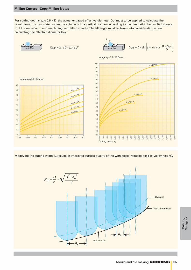
107
RthD D ae
ae
ae
4
2 2
2= -
-— —√—
0,1 0,15
1,5
2,0
2,0
3,0
2,5
3,0
3,5
4,0
4,5
5,0
5,5
6,0
6,5
0,2 0,25 0,3 0,35 0,4 0,45 0,5
0,50
1,00
1,50
2,00
2,50
3,00
3,50
4,00
4,50
5,00
5,50
6,00
6,50
7,00
7,50
8,00
8,50
9,00
9,50
10,0
0
D = 20mm
D = 16mm
D = 12mm
D = 10mm
D = 8mm
4,0
5,0
6,0
7,0
8,0
9,0
10,0
11,0
12,0
13,0
14,0
15,0
16,0
17,0
18,0
19,0
20,0D = 20mm
D = 16mm
D = 12mm
D = 10mm
D = 8mm
Deff
β
DeffD(eff) = 2 . D . ap - ap2 D(eff) = D . sin β + arc cos D - 2ap D
Mould and die making
Gü
hri
ng
Nav
igat
or
Milling Cutters - Copy Milling Notes
For cutting depths ap < 0.5 x D the actual engaged effective diameter Deff must to be applied to calculate the revolutions. It is calculated when the spindle is in a vertical position according to the illustration below. To increase tool life we recommend machining with tilted spindle. The tilt angle must be taken into consideration when calculating the effective diameter Deff.
Modifying the cutting width ae results in improved surface quality of the workpiece (reduced peak-to-valley height).
(range ap=0.1 - 0.5mm)
Act. contour
Cutting depth ap
(range ap=0.5 - 10.0mm)
Nom. dimension
Oversize
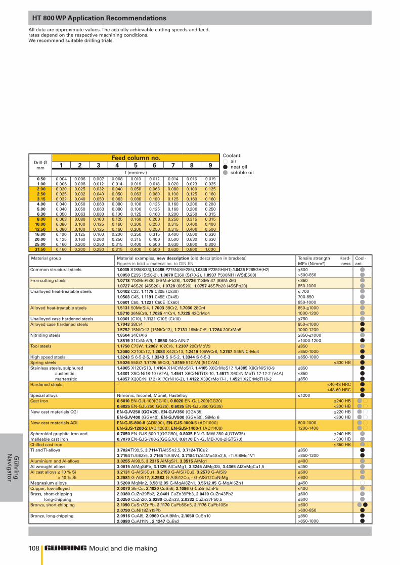
108
≤500>500-850≤850850-1000≤ 700700-850850-1000850-≤10001000-1200≤750850-≤10001000-1200≥850-≤1000>1000-1200≤850>850-1000≥650-1000
≤330 HB≤850≤850≤850
≤40-48 HRC>48-60 HRC
≤1200≤240 HB <300 HB ≤220 HB <300 HB
800-1000 1200-1400
≤240 HB<300 HB≤350 HB
≤850 >850-1200≤400≤450≤600≤600≤450≤400≤600≤600≤600 >600-850≤850>850-1000
Mould and die making
Gü
hrin
gN
avigator
HT 800 WP Application Recommendations
Coolant: air neat oil soluble oil
Drill-Ø mm
Feed column no.1 2 3 4 5 6 7 8 9
f (mm/rev.)0.50 0.004 0.006 0.007 0.008 0.010 0.012 0.014 0.016 0.0191.00 0.006 0.008 0.012 0.014 0.016 0.018 0.020 0.023 0.0252.00 0.020 0.025 0.032 0.040 0.050 0.063 0.080 0.100 0.1252.50 0.025 0.032 0.040 0.050 0.063 0.080 0.100 0.125 0.1603.15 0.032 0.040 0.050 0.063 0.080 0.100 0.125 0.160 0.1604.00 0.040 0.050 0.063 0.080 0.100 0.125 0.160 0.200 0.2005.00 0.040 0.050 0.063 0.080 0.100 0.125 0.160 0.200 0.2506.30 0.050 0.063 0.080 0.100 0.125 0.160 0.200 0.250 0.3158.00 0.063 0.080 0.100 0.125 0.160 0.200 0.250 0.315 0.315
10.00 0.080 0.100 0.125 0.160 0.200 0.250 0.315 0.400 0.40012.50 0.080 0.100 0.125 0.160 0.200 0.250 0.315 0.400 0.50016.00 0.100 0.125 0.160 0.200 0.250 0.315 0.400 0.500 0.63020.00 0.125 0.160 0.200 0.250 0.315 0.400 0.500 0.630 0.63025.00 0.160 0.200 0.250 0.315 0.400 0.500 0.630 0.800 0.80031.50 0.160 0.200 0.250 0.315 0.400 0.500 0.630 0.800 1.000
All data are approximate values. The actually achievable cutting speeds and feed rates depend on the respective machining conditions. We recommend suitable drilling trials.
Material group Material examples, new description (old description in brackets) Figures in bold = material no. to DIN EN
Tensile strength Hard-MPa (N/mm2) ness
Cool-ant
Common structural steels 1.0035 S185(St33),1.0486 P275N(StE285),1.0345 P235GH(H1),1.0425 P265GH(H2)1.0050 E295 (St50-2), 1.0070 E360 (St70-2), 1.8937 P500NH (WStE500)
Free-cutting steels 1.0718 11SMnPb30 (9SMnPb28), 1.0736 11SMn37 (9SMn36)1.0727 46S20 (45S20), 1.0728 (60S20), 1.0757 46SPb20 (45SPb20)
Unalloyed heat-treatable steels 1.0402 C22, 1.1178 C30E (Ck30)1.0503 C45, 1.1191 C45E (Ck45)1.0601 C60, 1.1221 C60E (Ck60)
Alloyed heat-treatable steels 1.5131 50MnSi4, 1.7003 38Cr2, 1.7030 28Cr41.5710 36NiCr6, 1.7035 41Cr4, 1.7225 42CrMo4
Unalloyed case hardened steels 1.0301 (C10), 1.1121 C10E (Ck10)Alloyed case hardened steels 1.7043 38Cr4
1.5752 15NiCr13 (15NiCr13), 1.7131 16MnCr5, 1.7264 20CrMo5Nitriding steels 1.8504 34CrAl6
1.8519 31CrMoV9, 1.8550 34CrAlNi7Tool steels 1.1750 C75W, 1.2067 102Cr6, 1.2307 29CrMoV9
1.2080 X210Cr12, 1.2083 X42Cr13, 1.2419 105WCr6, 1.2767 X45NiCrMo4High speed steels 1.3243 S 6-5-2-5, 1.3343 S 6-5-2, 1.3344 S 6-5-3Spring steels 1.5026 55Si7, 1.7176 55Cr3, 1.8159 51CrV4 (51CrV4)Stainless steels, sulphured 1.4005 X12CrS13, 1.4104 X14CrMoS17, 1.4105 X6CrMoS17, 1.4305 X8CrNiS18-9 austenitic 1.4301 X5CrNi18-10 (V2A), 1.4541 X6CrNiTi18-10, 1.4571 X6CrNiMoTi 17-12-2 (V4A) martensitic 1.4057 X20CrNi 17 2 (X17CrNi16-2), 1.4122 X39CrMo17-1, 1.4521 X2CrMoTi18-2Hardened steels –
Special alloys Nimonic, Inconel, Monel, HastelloyCast iron 0.6010 EN-GJL-100(GG10), 0.6020 EN-GJL-200(GG20)
0.6025 EN-GJL-250(GG25), 0.6035 EN-GJL-350(GG35)New cast materials CGI EN-GJV250 (GGV25), EN-GJV350 (GGV35)
EN-GJV400 (GGV40), EN-GJV500 (GGV50), SiMo 6New cast materials ADI EN-GJS-800-8 (ADI800), EN-GJS-1000-5 (ADI1000)
EN-GJS-1200-2 (ADI1200), EN-GJS-1400-1 (ADI1400)Spheroidal graphite iron and 0.7050 EN-GJS-500-7(GGG50), 0.8035 EN-GJMW-350-4(GTW35)malleable cast iron 0.7070 EN-GJS-700-2(GGG70), 0.8170 EN-GJMB-700-2(GTS70)Chilled cast iron –Ti and Ti-alloys 3.7024 Ti99,5, 3.7114 TiAl5Sn2,5, 3.7124 TiCu2
3.7154 TiAl6Zr5, 3.7165 TiAl6V4, 3.7184 TiAl4Mo4Sn2,5, - TiAl8Mo1V1Aluminium and Al-alloys 3.0255 Al99,5, 3.2315 AlMgSi1, 3.3515 AlMg1Al wrought alloys 3.0615 AlMgSiPb, 3.1325 AlCuMg1, 3.3245 AlMg3Si, 3.4365 AlZnMgCu1,5Al cast alloys ≤ 10 % Si 3.2131 G-AlSi5Cu1, 3.2153 G-AlSi7Cu3, 3.2573 G-AlSi9 > 10 % Si 3.2581 G-AlSi12, 3.2583 G-AlSi12Cu, - G-AlSi12CuNiMgMagnesium alloys 3.5200 MgMn2, 3.5812.05 G-MgAl8Zn1, 3.5612.05 G-MgAl6Zn1Copper, low-alloyed 2.0070 SE-Cu, 2.1020 CuSn6, 2.1096 G-CuSn5ZnPbBrass, short-chipping 2.0380 CuZn39Pb2, 2.0401 CuZn39Pb3, 2.0410 CuZn43Pb2 long-chipping 2.0250 CuZn20, 2.0280 CuZn33, 2.0332 CuZn37Pb0,5Bronze, short-chipping 2.1090 CuSn7ZnPb, 2.1170 CuPb5Sn5, 2.1176 CuPb10Sn
2.0790 CuNi18Zn19PbBronze, long-chipping 2.0916 CuAl5, 2.0960 CuAl9Mn, 2.1050 CuSn10
2.0980 CuAl11Ni, 2.1247 CuBe2
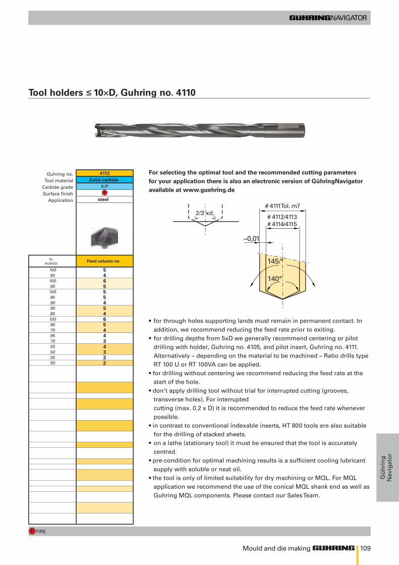
109
FIRE
145/°
140°
~0,01
# 4111Tol. m7
# 4112/4113# 4114/4115
2/3 xd1
4112
K/P
100 595 4100 695 5100 595 590 490 585 4100 690 570 495 470 355 450 355 250 2
Mould and die making
Gü
hri
ng
Nav
igat
or
Tool holders ≤ 10×D, Guhring no. 4110
Feed column no.
Guhring no.Tool material
Carbide gradeSurface finish
Application
Solid carbide
steel
vc m/min
For selecting the optimal tool and the recommended cutting parameters for your application there is also an electronic version of GühringNavigator available at www.guehring.de
• for through holes supporting lands must remain in permanent contact. In addition, we recommend reducing the feed rate prior to exiting.
• for drilling depths from 5xD we generally recommend centering or pilot drilling with holder, Guhring no. 4105, and pilot insert, Guhring no. 4111. Alternatively – depending on the material to be machined – Ratio drills type RT 100 U or RT 100VA can be applied.
• for drilling without centering we recommend reducing the feed rate at the start of the hole.
• don‘t apply drilling tool without trial for interrupted cutting (grooves, transverse holes). For interrupted
cutting (max. 0.2 x D) it is recommended to reduce the feed rate whenever possible.
• in contrast to conventional indexable inserts, HT 800 tools are also suitable for the drilling of stacked sheets.
• on a lathe (stationary tool) it must be ensured that the tool is accurately centred.
• pre-condition for optimal machining results is a sufficient cooling lubricant supply with soluble or neat oil.
• the tool is only of limited suitability for dry machining or MQL. For MQL application we recommend the use of the conical MQL shank end as well as Guhring MQL components. Please contact our Sales Team.
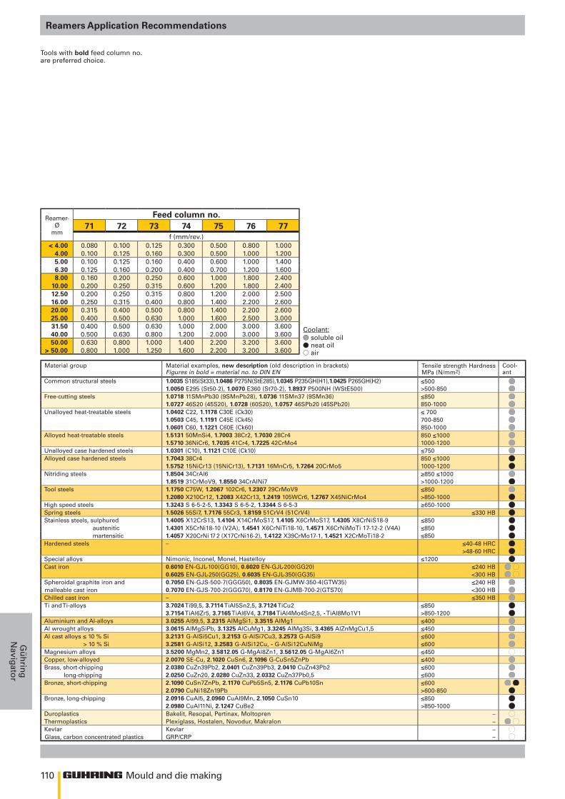
110
≤500>500-850≤850850-1000≤ 700700-850850-1000850 ≤10001000-1200≤750850 ≤10001000-1200≥850 ≤1000>1000-1200≤850>850-1000≥650-1000
≤330 HB≤850≤850≤850
≤40-48 HRC>48-60 HRC
≤1200≤240 HB <300 HB ≤240 HB<300 HB≤350 HB
≤850 >850-1200≤400≤450≤600≤600≤450≤400≤600≤600≤600 >600-850≤850>850-1000
–– ––
Mould and die making
Gü
hrin
gN
avigator
Tools with bold feed column no. are preferred choice.
soluble oilneat oilair
Coolant:
Reamer-Ø
mm
Feed column no.71 72 73 74 75 76 77
f (mm/rev.)< 4.00 0.080 0.100 0.125 0.300 0.500 0.800 1.000
4.00 0.100 0.125 0.160 0.300 0.500 1.000 1.2005.00 0.100 0.125 0.160 0.400 0.600 1.000 1.4006.30 0.125 0.160 0.200 0.400 0.700 1.200 1.6008.00 0.160 0.200 0.250 0.600 1.000 1.800 2.400
10.00 0.200 0.250 0.315 0.600 1.200 1.800 2.40012.50 0.200 0.250 0.315 0.800 1.200 2.000 2.50016.00 0.250 0.315 0.400 0.800 1.400 2.200 2.60020.00 0.315 0.400 0.500 0.800 1.400 2.200 2.60025.00 0.400 0.500 0.630 1.000 1.600 2.500 3.00031.50 0.400 0.500 0.630 1.000 2.000 3.000 3.60040.00 0.500 0.630 0.800 1.200 2.000 3.000 3.60050.00 0.630 0.800 1.000 1.400 2.200 3.200 3.600
> 50.00 0.800 1.000 1.250 1.600 2.200 3.200 3.600
Reamers Application Recommendations
Guhring no.Tool material
StandardTypeForm
Surface finishCooling
Material group Material examples, new description (old description in brackets) Figures in bold = material no. to DIN EN
Tensile strength Hardness MPa (N/mm2)
Cool-ant
Common structural steels 1.0035 S185(St33),1.0486 P275N(StE285),1.0345 P235GH(H1),1.0425 P265GH(H2)1.0050 E295 (St50-2), 1.0070 E360 (St70-2), 1.8937 P500NH (WStE500)
Free-cutting steels 1.0718 11SMnPb30 (9SMnPb28), 1.0736 11SMn37 (9SMn36)1.0727 46S20 (45S20), 1.0728 (60S20), 1.0757 46SPb20 (45SPb20)
Unalloyed heat-treatable steels 1.0402 C22, 1.1178 C30E (Ck30)1.0503 C45, 1.1191 C45E (Ck45)1.0601 C60, 1.1221 C60E (Ck60)
Alloyed heat-treatable steels 1.5131 50MnSi4, 1.7003 38Cr2, 1.7030 28Cr41.5710 36NiCr6, 1.7035 41Cr4, 1.7225 42CrMo4
Unalloyed case hardened steels 1.0301 (C10), 1.1121 C10E (Ck10)Alloyed case hardened steels 1.7043 38Cr4
1.5752 15NiCr13 (15NiCr13), 1.7131 16MnCr5, 1.7264 20CrMo5Nitriding steels 1.8504 34CrAl6
1.8519 31CrMoV9, 1.8550 34CrAlNi7Tool steels 1.1750 C75W, 1.2067 102Cr6, 1.2307 29CrMoV9
1.2080 X210Cr12, 1.2083 X42Cr13, 1.2419 105WCr6, 1.2767 X45NiCrMo4High speed steels 1.3243 S 6-5-2-5, 1.3343 S 6-5-2, 1.3344 S 6-5-3Spring steels 1.5026 55Si7, 1.7176 55Cr3, 1.8159 51CrV4 (51CrV4)Stainless steels, sulphured 1.4005 X12CrS13, 1.4104 X14CrMoS17, 1.4105 X6CrMoS17, 1.4305 X8CrNiS18-9 austenitic 1.4301 X5CrNi18-10 (V2A), 1.4541 X6CrNiTi18-10, 1.4571 X6CrNiMoTi 17-12-2 (V4A) martensitic 1.4057 X20CrNi 17 2 (X17CrNi16-2), 1.4122 X39CrMo17-1, 1.4521 X2CrMoTi18-2Hardened steels –
Special alloys Nimonic, Inconel, Monel, HastelloyCast iron 0.6010 EN-GJL-100(GG10), 0.6020 EN-GJL-200(GG20)
0.6025 EN-GJL-250(GG25), 0.6035 EN-GJL-350(GG35)Spheroidal graphite iron and 0.7050 EN-GJS-500-7(GGG50), 0.8035 EN-GJMW-350-4(GTW35)malleable cast iron 0.7070 EN-GJS-700-2(GGG70), 0.8170 EN-GJMB-700-2(GTS70)Chilled cast iron –Ti and Ti-alloys 3.7024 Ti99,5, 3.7114 TiAl5Sn2,5, 3.7124 TiCu2
3.7154 TiAl6Zr5, 3.7165 TiAl6V4, 3.7184 TiAl4Mo4Sn2,5, - TiAl8Mo1V1Aluminium and Al-alloys 3.0255 Al99,5, 3.2315 AlMgSi1, 3.3515 AlMg1Al wrought alloys 3.0615 AlMgSiPb, 3.1325 AlCuMg1, 3.3245 AlMg3Si, 3.4365 AlZnMgCu1,5Al cast alloys ≤ 10 % Si 3.2131 G-AlSi5Cu1, 3.2153 G-AlSi7Cu3, 3.2573 G-AlSi9 > 10 % Si 3.2581 G-AlSi12, 3.2583 G-AlSi12Cu, - G-AlSi12CuNiMgMagnesium alloys 3.5200 MgMn2, 3.5812.05 G-MgAl8Zn1, 3.5612.05 G-MgAl6Zn1Copper, low-alloyed 2.0070 SE-Cu, 2.1020 CuSn6, 2.1096 G-CuSn5ZnPbBrass, short-chipping 2.0380 CuZn39Pb2, 2.0401 CuZn39Pb3, 2.0410 CuZn43Pb2 long-chipping 2.0250 CuZn20, 2.0280 CuZn33, 2.0332 CuZn37Pb0,5Bronze, short-chipping 2.1090 CuSn7ZnPb, 2.1170 CuPb5Sn5, 2.1176 CuPb10Sn
2.0790 CuNi18Zn19PbBronze, long-chipping 2.0916 CuAl5, 2.0960 CuAl9Mn, 2.1050 CuSn10
2.0980 CuAl11Ni, 2.1247 CuBe2Duroplastics Bakelit, Resopal, Pertinax, MoltoprenThermoplastics Plexiglass, Hostalen, Novodur, MakralonKevlar KevlarGlass, carbon concentrated plastics GRP/CRP
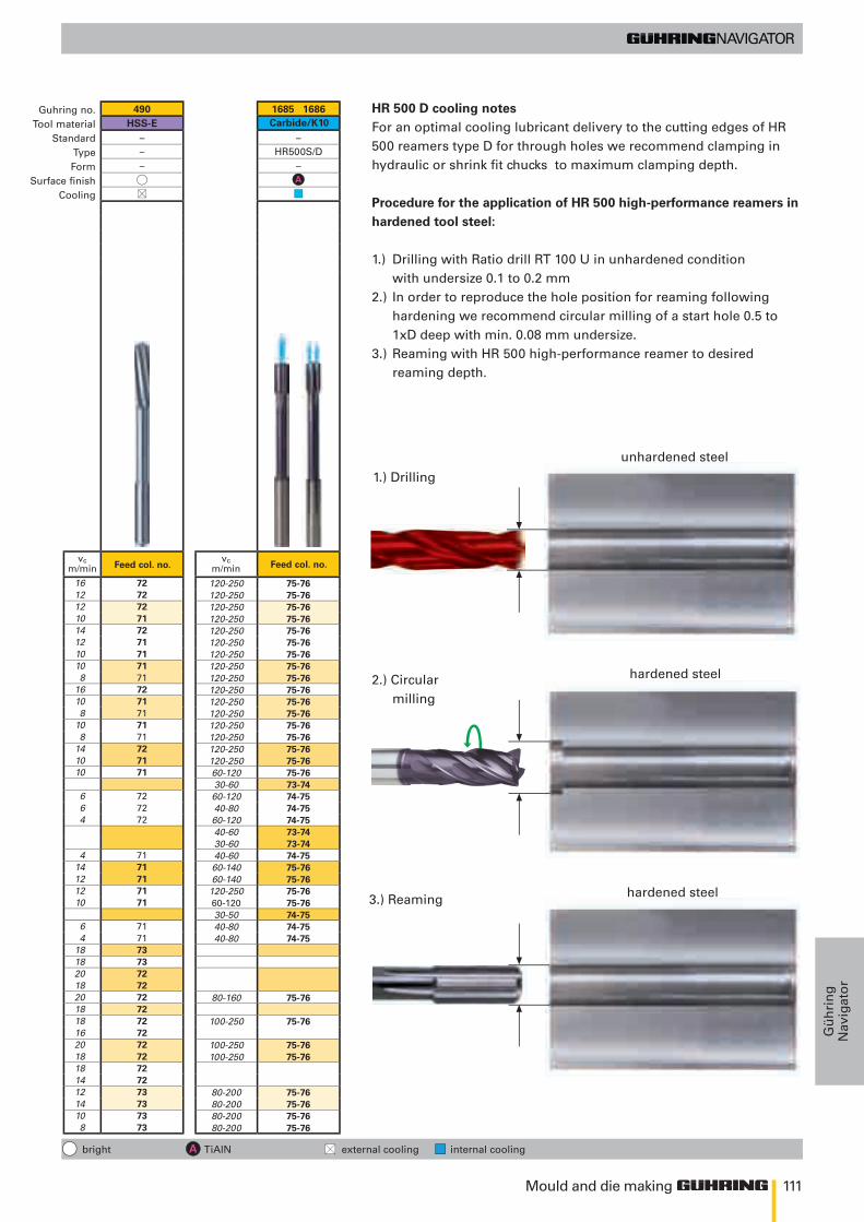
111
490HSS-E
–––
1685 1686
–HR500S/D
–
16 7212 7212 7210 7114 7212 7110 7110 718 71
16 7210 718 71
10 718 71
14 7210 7110 71
6 726 724 72
4 7114 7112 7112 7110 71
6 714 71
18 7318 7320 7218 7220 7218 7218 7216 7220 7218 7218 7214 7212 7314 7310 738 73
120-250 75-76120-250 75-76120-250 75-76120-250 75-76120-250 75-76120-250 75-76120-250 75-76120-250 75-76120-250 75-76120-250 75-76120-250 75-76120-250 75-76120-250 75-76120-250 75-76120-250 75-76120-250 75-7660-120 75-7630-60 73-7460-120 74-7540-80 74-7560-120 74-7540-60 73-7430-60 73-7440-60 74-7560-140 75-7660-140 75-76
120-250 75-7660-120 75-7630-50 74-7540-80 74-7540-80 74-75
80-160 75-76
100-250 75-76
100-250 75-76100-250 75-76
80-200 75-7680-200 75-7680-200 75-7680-200 75-76
Mould and die making
Gü
hri
ng
Nav
igat
or
Carbide/K10
Feed col. no. Feed col. no.vc
m/minvc
m/min
Guhring no.Tool material
StandardTypeForm
Surface finishCooling
HR 500 D cooling notesFor an optimal cooling lubricant delivery to the cutting edges of HR 500 reamers type D for through holes we recommend clamping in hydraulic or shrink fit chucks to maximum clamping depth.
Procedure for the application of HR 500 high-performance reamers in hardened tool steel:
1.) Drilling with Ratio drill RT 100 U in unhardened condition with undersize 0.1 to 0.2 mm
2.) In order to reproduce the hole position for reaming following hardening we recommend circular milling of a start hole 0.5 to 1xD deep with min. 0.08 mm undersize.
3.) Reaming with HR 500 high-performance reamer to desired reaming depth.
hardened steel
1.) Drilling
2.) Circular milling
3.) Reaming
hardened steel
unhardened steel
bright TiAlN external cooling internal cooling
B.indd 1 12.11.10 10:17
112
805/
1134
-VIII
-16
• Pri
nte
d in
Ger
man
yGühring oHGPostfach 100247 • 72423 AlbstadtHerderstraße 50-54 • 72458 Albstadt
Tel. +49 74 31 17-0Fax +49 74 31 17-21 [email protected]
No liability can be accepted for printing errors or technical changes of any kind.Our Conditions of Sale and Terms of Payment apply. Available on request.Price list 41, January 2009.
Drilling
PCD
milling
Countersinking
Modular tooling systeMs
Tool resTool resTToraoraToraTToraT TToraToraoraTora ion serviceion service