Embed Size (px)
Citation preview
CoLLaPsibLe Cores
Material and hardnessa) The centre pin is manufactured from high qualityalloy steel 1.2436, hardened to 60-65 HRC. Centre pins forStandard as well as for Mini Collapsible Cores are fittedto a specific core and cannot be interchanged. This is dueto the centre pin and core sleeve being assembled andground together.b) Core sleeves are manufactured in a 1.2363 steel(AISI 01) and hardened to 55-60 HRC. All centre pins andcore sleeves carry a serial number. Always verify the serialnumber prior to grinding or final assembly.c) The positive collapse sleeve is manufactured intool steel and hardened to 55 ± 5 HRC. It is designed tofunction when the Collapsible Core fails to collapse inde-pendently upon withdrawal of the centre pin. Its aim is anadditional and necessary safety factor.
What materials can be molded?All commonly used thermoplastic molding resins. For many years filled and non-filled molding resins have been successfully molded. Special requirements have to be taken into consideration when PVC is processed. When using the Mini or Standard Collapsible Cores for process-ing this material it is recommended you contact DME.
Info CCM-CC
General description of the Collapsible Cores
It is over 30 years since DME first introduced the Collapsible Core and today it still continues to be a major influence for mold-ing plastic parts requiring internal threads, undercuts, cut-outs etc. During this time a lot of technical knowledge and experi-ence has been gained from many applications tackled, some of which have been very complicated. This “Know how” has been constantly passed on to the user, either through new devel-opments, application improvements or suggestions for new applications. One such development is the new range smaller diameters which complete the series of Collapsible Cores. The Collapsible Cores now range from 18 mm to 107 mm, for the outer diameters with the corresponding inner diameter ranging from 16 mm to 85 mm. The effective collapse ranges from 1.1 mm to 4,2 mm per side at the tip of the Core, depending on the diameter of the Core.
Operation
After cooling, the mold opens and the ejector plate assembly moves forward as far as the stop. This causes the core sleeve to move away from the centre pin and the positive collapsed sleeve to engage, which ensures that all segments have col-lapsed. However, the molded part remains or hangs until the stripper plate is moved forward to eject the components. This is usually carried out by the activation of two double acting air cylinders mounted on the ejector plates and connected to the stripper plate on the outside of the mold. The stripper plate is then retracted using the two air cylinders before the mold is closed. When closing the mold, one has to ensure that the ejec-tor plates are returned before the mold is fully closed. This can be achieved by the use of early ejector returns. The core sleeve is returned to the molding position thus preventing damage to the Collapsible Cores. When the mold is fully closed the next cycle can begin. When using Collapsible Cores the designer has a product which offers many opportunities for producing many variations of molded caps. The result is a mold which functions reliably and economically irrespective of whether it concerns a single or multiple cavity mold. Parts with internal protrusions, dimples, interrupted threads and cut-outs can be economically produced on a high or low volume basis. It should be noted that due to the design of the Mini Collapsible Core only interrupted threads and undercuts can be produced. The interruptions con-sist of three small slots with width “J” (See table), but in most cases this does not imply any technical disadvantages.
Design Procedure
The following steps are used to determine if a part can be mold-ed on the Mini or Standard Collapsible Core:a) Calculate the expected actual shrinkage “S” = part Ø x shrink-
age (%) “S1” = part length x shrinkage (%)b) Determine that the part minor diameter “A” is not less than “A
min” (See table and Fig 1)c) Determine that the part major diameter “B” is not greater
than “B max” (See table and Fig 1)
d) Determine that thread depth or part undercut at “L”does not exceed the calculated dimension “C” (seeTable and Fig.1). The collapse available decreasesfrom the front of the core at a rate of 0,02 mm/mm.When the amount of collapse “C” of the Mini or StandardCollapsible Cores is insufficient, Collapsible Cores of thesame size but with a greater collapse can be obtained.
e) Determine that part depth “D” (Fig 1) doesnot exceed the value “D” given in the table. Dimension “K min” of the table must be equal to or larger than “K min”.
Type CK Max.CCM-0001 1.45 mm/side CCM-0002 1.60 mm/side CCM-0003 1.80 mm/side CC 125 PC 0.80 mm/sideCC 150 PC 1.07 mm/sideCC 175 PC 1.20 mm/sideCC 250 PC 1.20 mm/side
Type CK Max.CC 252 PC 1.60 mm/side CC 352 PC 2.10 mm/sideCC 402 PC 2.65 mm/sideCC 502 PC 3.20 mm/sideCC 602 PC 3.75 mm/sideCC 652 PC 4.06 mm/sideCC 702 PC 4.32 mm/side
CK = Collapse per side at top of core.
www.diemouldequipment.com.au Tel 1800 224 135
CoLLaPsibLe Cores
Info CCM-CC
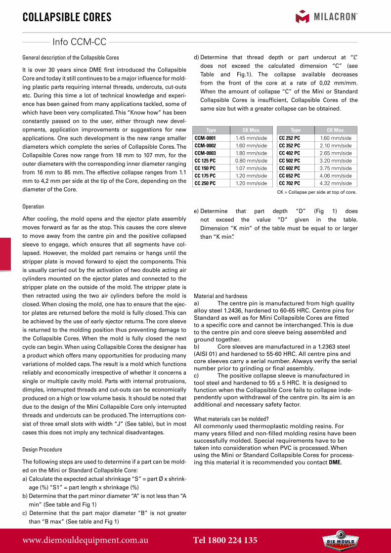
Part design - special requirementsFor successful operation the design of the part must fulfil the following requirements:a) In contrast with the Standard Collapsible Core it is notpossible to mold parts with full threads with the MiniCollapsible Core. The three remaining “marks” on the partresult from the three interrupted areas with width “J” ofthe non-collapsing centre pin blades. Make sure that thetop of the centre pin protrudes beyond the top of the coresleeve.b) The centre pin must protrude beyond the core face byat least the distance “F”. Protrusions down to “F min” areacceptable but “F max” is recommended. For “F min” and“F max” see Table or Collapsible Core dimensions leaflet.Radius “R” is most important. For “R min” and “R max”see Collapsible Core dimension drawing.c) There must be no undercuts on the face of the core seg-ments. This will prevent the Collapsible Core from func-tioning.d) Undercuts on the face of the pin must not interfere withfull radial movement of the core. They must be locatedeither forward of the core face or within a diameter small-er than “G” (see Table, Fig 3; max 4 mm - see CollapsibleCore dimension drawing). In no case should the under-cuts be so deep that they come close to the cooling linesin the centre pin. For special requirements please contactDME.e) The core face must have a draft of at least 3° startingno further than 0.8 mm from the top of the pin. A greaterdraft is desirable when “B” is near “B max” (ex. 4-5°).f) All undercuts should be drafted. A minimum draft of5° is required (see Table, fig 3), more is recommended.Interrupted undercuts also require a side draft of at last 5°.
g) Means must be provided for carrying the molded partoff of the collapsed core at the completion of the ejectionstroke. This is normally done by providing a ring projec-tion (0.25 x 0.25 mm) on the face of the stripper stroke.The part must not drag over the core (see detail Y onCollapsible Core dimensions leaflet).h) As in conventional practice, sharp interior corners mustbe avoided to prevent stress concentration in the steel.Never permit a ground thread to run out through the faceof the core. This leaves a knife edge of steel that will breakoff in time.
www.diemouldequipment.com.au Tel 1800 224 135
CCM
CoLLaPsibLe Cores
Collapsible mini-cores
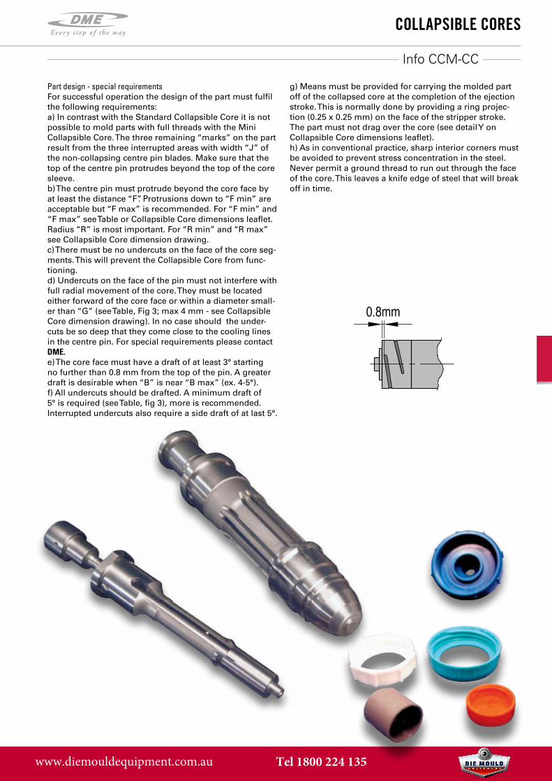
Molded cap
Collapsingsegments (3)
Non-collapsingcenter pin blades (3)
Stripper plate
Positive collapse sleeve (included)
Core sleeve with(3) collapsing segments
Center pin with (3) non-collapsing bladesEjector plate assembly
Cooling hole incenter pin
Alignment flats on coresleeve and center pin
Shut
-off
REFA. Part
Minor Ø (min.)
B. Part Major Ø (max.)
C. Maximum part under-
cut at L
D. Maximum part depth
E. Length of fitted sur-
face on core
F. Pin pro-trusion,
min.
G. Inside diameter collapsed core nom
H. Pin diameter at face
(nominal)
K. Stripper bushing shut-off
J. Width of non-
collapsingR. Pin tip
radiusS. Material shrinkage
CCM 0001 10,80-S 16,38-S 1,30-(0,02L+0,5S) 21,60-S1-K 21,60 0,4 (0,8 max) 2,30 7,60 4,00 4 0,20
S= Shrinkage factor (%)
x Part diam-eter (mm)
S1= Shrinkage factor (%)
x Part length (mm)
CCM 0002 14,22-S 20,45-S 1,45-(0,02L+0,5S) 21,60-S1-K 21,60 0,4 (0,8 max) 4,60 10,70 4,83 4 0,20
CCM 0003 18,03-S 24,51-S 1,50-(0,02L+0,5S) 25,40-S1-K 25,40 0,4 (0,8 max) 7,90 14,20 5,08 4 0,20
www.diemouldequipment.com.au Tel 1800 224 135
CC
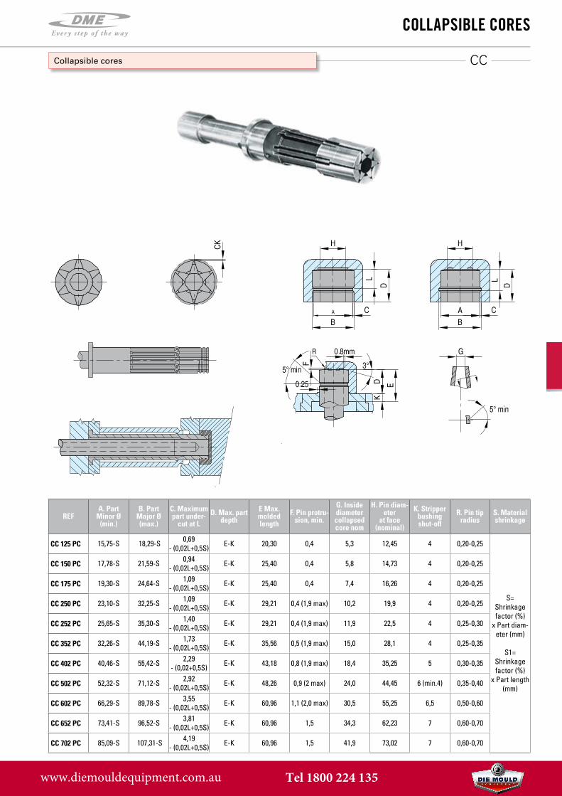
CoLLaPsibLe Cores
Collapsible cores
REFA. Part
Minor Ø (min.)
B. Part Major Ø (max.)
C. Maximum part under-
cut at LD. Max. part
depthE Max. molded length
F. Pin protru-sion, min.
G. Inside diameter collapsed core nom
H. Pin diam-eter
at face (nominal)
K. Stripperbushing shut-off
R. Pin tip radius
S. Materialshrinkage
CC 125 PC 15,75-S 18,29-S 0,69- (0,02L+0,5S) E-K 20,30 0,4 5,3 12,45 4 0,20-0,25
S= Shrinkage factor (%)
x Part diam-eter (mm)
S1= Shrinkage factor (%)
x Part length (mm)
CC 150 PC 17,78-S 21,59-S 0,94- (0,02L+0,5S) E-K 25,40 0,4 5,8 14,73 4 0,20-0,25
CC 175 PC 19,30-S 24,64-S 1,09- (0,02L+0,5S) E-K 25,40 0,4 7,4 16,26 4 0,20-0,25
CC 250 PC 23,10-S 32,25-S 1,09- (0,02L+0,5S) E-K 29,21 0,4 (1,9 max) 10,2 19,9 4 0,20-0,25
CC 252 PC 25,65-S 35,30-S 1,40- (0,02L+0,5S) E-K 29,21 0,4 (1,9 max) 11,9 22,5 4 0,25-0,30
CC 352 PC 32,26-S 44,19-S 1,73- (0,02L+0,5S) E-K 35,56 0,5 (1,9 max) 15,0 28,1 4 0,25-0,35
CC 402 PC 40,46-S 55,42-S 2,29- (0,02+0,5S) E-K 43,18 0,8 (1,9 max) 18,4 35,25 5 0,30-0,35
CC 502 PC 52,32-S 71,12-S 2,92- (0,02L+0,5S) E-K 48,26 0,9 (2 max) 24,0 44,45 6 (min.4) 0,35-0,40
CC 602 PC 66,29-S 89,78-S 3,55- (0,02L+0,5S) E-K 60,96 1,1 (2,0 max) 30,5 55,25 6,5 0,50-0,60
CC 652 PC 73,41-S 96,52-S 3,81- (0,02L+0,5S) E-K 60,96 1,5 34,3 62,23 7 0,60-0,70
CC 702 PC 85,09-S 107,31-S 4,19- (0,02L+0,5S) E-K 60,96 1,5 41,9 73,02 7 0,60-0,70
www.diemouldequipment.com.au Tel 1800 224 135
CC
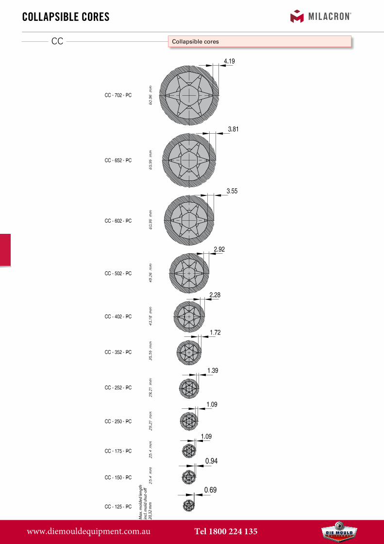
CoLLaPsibLe Cores
Collapsible cores
Max
. mol
ded
leng
thin
cl. m
old
shut
-o�
20,3
2 m
m
Max
. mol
ded
leng
thin
cl. m
old
shut
-o�
21,5
9 m
m
www.diemouldequipment.com.au Tel 1800 224 135
CC
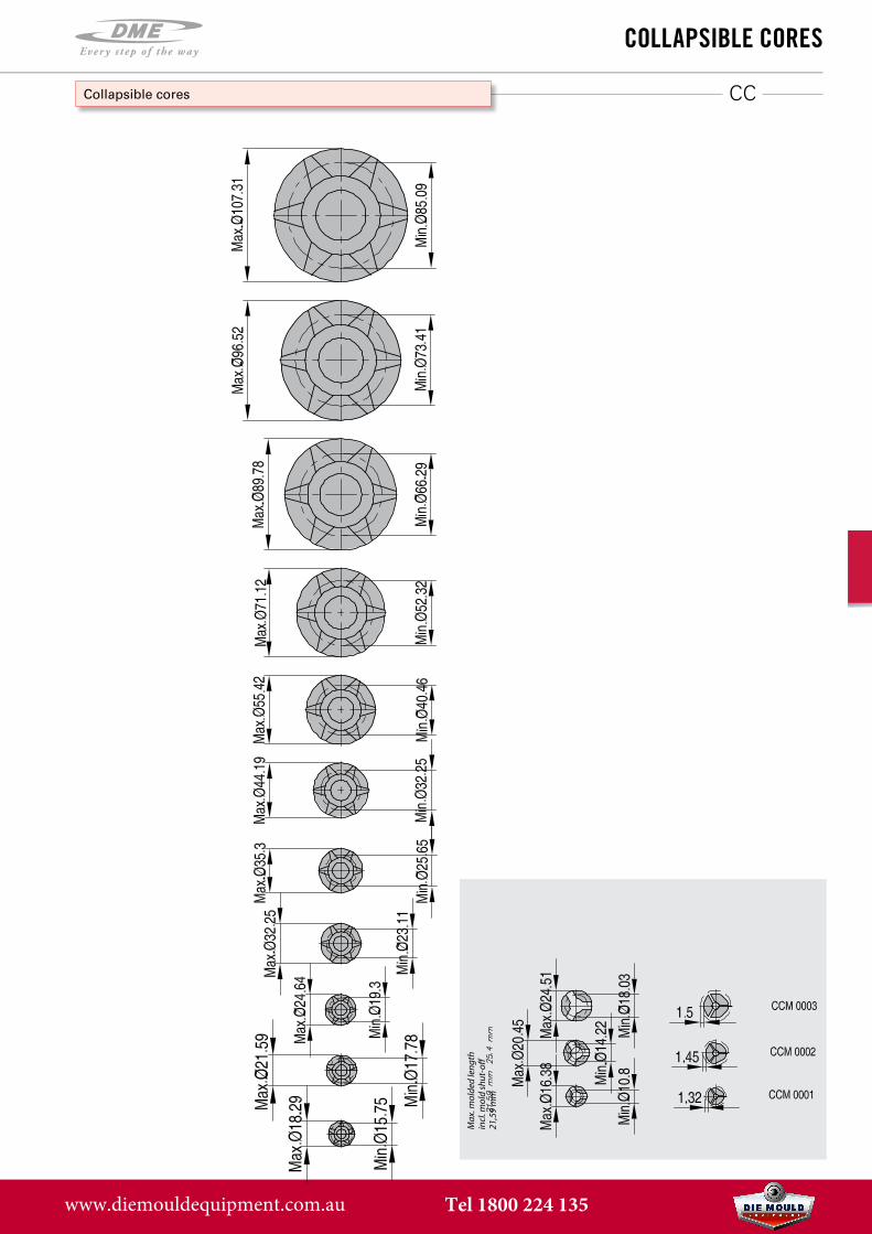
CoLLaPsibLe Cores
Collapsible cores
Max
. mol
ded
leng
thin
cl. m
old
shut
-o�
20,3
2 m
m Max
. mol
ded
leng
thin
cl. m
old
shut
-o�
21,5
9 m
m
www.diemouldequipment.com.au Tel 1800 224 135
EXCAV
EXC ... BH/BP
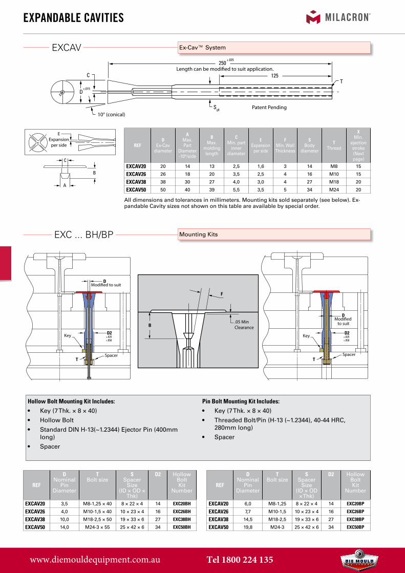
exPandabLe CaVities
Ex-Cav™ System
250
±.015
C
D
C
B
A
125T
Sg6
±.025
10° (conical)
EExpansion
per side
Length can be modi�ed to suit application.
Patent Pending
REF
DNominal
Pin Diameter
T Bolt size
SSpacer
Size (ID × OD ×
Thk)
D2 Hollow Bolt Kit
Number
EXCAV20 3,5 M8-1,25 × 40 8 × 22 × 4 14 EXC20BH
EXCAV26 4,0 M10-1,5 × 40 10 × 23 × 4 16 EXC26BH
EXCAV38 10,0 M18-2,5 × 50 19 × 33 × 6 27 EXC38BH
EXCAV50 14,0 M24-3 × 55 25 × 42 × 6 34 EXC50BH
REF
DNominal
Pin Diameter
T Bolt size
SSpacer
Size (ID × OD
× Thk)
D2 Hollow Bolt Kit
Number
EXCAV20 6,0 M8-1,25 8 × 22 × 4 14 EXC20BP
EXCAV26 7,7 M10-1,5 10 × 23 × 4 16 EXC26BP
EXCAV38 14,5 M18-2,5 19 × 33 × 6 27 EXC38BP
EXCAV50 19,8 M24-3 25 × 42 × 6 34 EXC50BP
REFD
Ex-Cavdiameter
A Max. Part
Diameter -10°/side
BMax.
molding length
C Min. part
inner diameter
EExpansion
per side
FMin. Wall Thickness
SBody
diameter
TThread
XMin.
ejection stroke (Next page)
EXCAV20 20 14 13 2,5 1,6 3 14 M8 15
EXCAV26 26 18 20 3,5 2,5 4 16 M10 15
EXCAV38 38 30 27 4,0 3,0 4 27 M18 20
EXCAV50 50 40 39 5,5 3,5 5 34 M24 20
All dimensions and tolerances in millimeters. Mounting kits sold separately (see below). Ex-pandable Cavity sizes not shown on this table are available by special order.
Mounting Kits
D
D2
D
T T
+.025+.050
D2+.025+.050
Modi�ed to suit
Key Key
Spacer Spacer
Modi�ed to suit
D
D2
D
T T
+.025+.050
D2+.025+.050
Modi�ed to suit
Key Key
Spacer Spacer
Modi�ed to suit
F
B.05 MinClearance
250
±.015
C
D
C
B
A
125T
Sg6
±.025
10° (conical)
EExpansion
per side
Length can be modi�ed to suit application.
Patent Pending
Hollow Bolt Mounting Kit Includes:
• Key (7 Thk. × 8 × 40)
• Hollow Bolt
• Standard DIN H-13(~1.2344) Ejector Pin (400mmlong)
• Spacer
Pin Bolt Mounting Kit Includes:
• Key (7 Thk. × 8 × 40)
• Threaded Bolt/Pin (H-13 (~1.2344), 40-44 HRC,280mm long)
• Spacer
www.diemouldequipment.com.au Tel 1800 224 135
MinimumEjector Stroke
MinimumEjector Stroke
exPandabLe CaVities
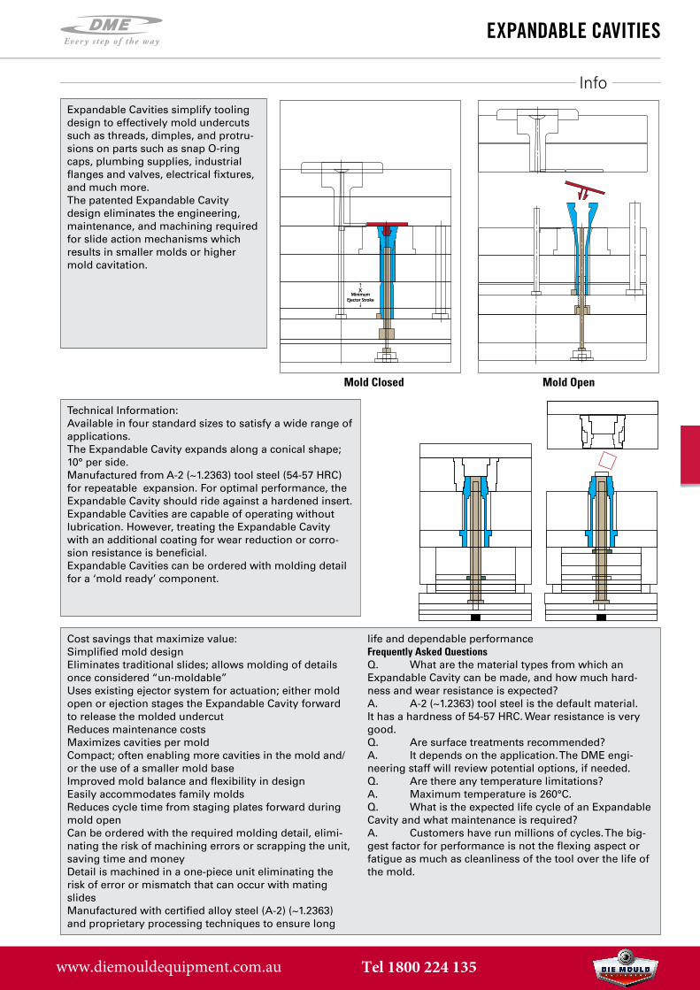
Mold Closed Mold Open
Expandable Cavities simplify tooling design to effectively mold undercuts such as threads, dimples, and protru-sions on parts such as snap O-ring caps, plumbing supplies, industrial flanges and valves, electrical fixtures, and much more.The patented Expandable Cavity design eliminates the engineering, maintenance, and machining required for slide action mechanisms which results in smaller molds or higher mold cavitation.
Technical Information:Available in four standard sizes to satisfy a wide range of applications.The Expandable Cavity expands along a conical shape; 10° per side.Manufactured from A-2 (~1.2363) tool steel (54-57 HRC) for repeatable expansion. For optimal performance, the Expandable Cavity should ride against a hardened insert.Expandable Cavities are capable of operating without lubrication. However, treating the Expandable Cavity with an additional coating for wear reduction or corro-sion resistance is beneficial.Expandable Cavities can be ordered with molding detail for a ‘mold ready’ component.
Cost savings that maximize value:Simplified mold designEliminates traditional slides; allows molding of details once considered “un-moldable”Uses existing ejector system for actuation; either mold open or ejection stages the Expandable Cavity forward to release the molded undercutReduces maintenance costsMaximizes cavities per moldCompact; often enabling more cavities in the mold and/or the use of a smaller mold baseImproved mold balance and flexibility in designEasily accommodates family moldsReduces cycle time from staging plates forward during mold openCan be ordered with the required molding detail, elimi-nating the risk of machining errors or scrapping the unit, saving time and moneyDetail is machined in a one-piece unit eliminating the risk of error or mismatch that can occur with mating slidesManufactured with certified alloy steel (A-2) (~1.2363) and proprietary processing techniques to ensure long
life and dependable performanceFrequently Asked QuestionsQ. What are the material types from which anExpandable Cavity can be made, and how much hard-ness and wear resistance is expected?A. A-2 (~1.2363) tool steel is the default material.It has a hardness of 54-57 HRC. Wear resistance is verygood.Q. Are surface treatments recommended?A. It depends on the application. The DME engi-neering staff will review potential options, if needed.Q. Are there any temperature limitations?A. Maximum temperature is 260°C.Q. What is the expected life cycle of an ExpandableCavity and what maintenance is required?A. Customers have run millions of cycles. The big-gest factor for performance is not the flexing aspect orfatigue as much as cleanliness of the tool over the life ofthe mold.
Info
www.diemouldequipment.com.au Tel 1800 224 135
dt series CoLLaPsibLe Cores
C
CD
D
BC
T (3)
ML
CT
S
SLL
B BD
BH
SD
60˚ grinding centerprovided on both ends.(Grind to suit.)
Flats forin-press
servicing
120˚(Typ.)
10˚
Stroke
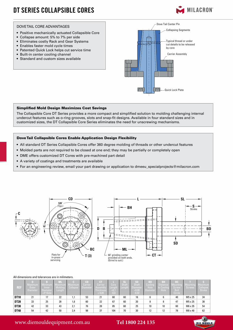
DOVE TAIL CORE ADVANTAGES
• Positive mechanically actuated Collapsible Core• Collapse amount: 5% to 7% per side• Eliminates costly Rack and Gear Systems• Enables faster mold cycle times• Patented Quick Lock helps cut service time• Built-in center cooling channel• Standard and custom sizes available
Simplified Mold Design Maximizes Cost Savings
The Collapsible Core DT Series provides a more compact and simplified solution to molding challenging internal undercut features such as o-ring grooves, slots and snap-fit designs. Available in four standard sizes and in customized sizes, the DT Collapsible Core Series eliminates the need for unscrewing mechanisms.
Dove Tail Collapsible Cores Enable Application Design Flexibility
• All standard DT Series Collapsible Cores offer 360 degree molding of threads or other undercut features
• Molded parts are not required to be closed at one end; they may be partially or completely open
• DME offers customized DT Cores with pre-machined part detail
• A variety of coatings and treatments are available
• For an engineering review, email your part drawing or application to [email protected]
REF
DMaximum
Outer Diameter
B Minimum
Inner Diameter +3°/Side
MLMaximum Molding Length
CMaximum Collapse
CDCarrier
Diameter
CTCarrier
Assembly Thickness
± 0,05
LCore
Length +0,1-0,0
SLShaft
Length
SDShaft
Diameter+0,00 -0,02
BDCooling
HoleDiameter
BHDistance
to Cooling Hole
BCMounting
Screw Bolt
Circle
TMounting Screws
SMaximum Collapse Stroke
DT18 21 17 22 1,1 53 21 60 60 16 6 6 40 M5 x 25 34
DT28 33 25 28 1,6 60 22 67 60 20 8 8 47 M5 x 25 38
DT38 42 33 43 2,1 76 28 85 60 25 10 10 60 M6 x 35 54
DT48 54 42 50 2,4 98 37 104 70 30 12 12 78 M8 x 40 62
Dove Tail Center Pin
Collapsing Segments
Carrier Assembly
Quick Lock Plate
Typical thread or under cut details to be released by core
All dimensions and tolerances are in milimeters.
www.diemouldequipment.com.au Tel 1800 224 135
349 store.milacron.com
EXP
REFEXP ****
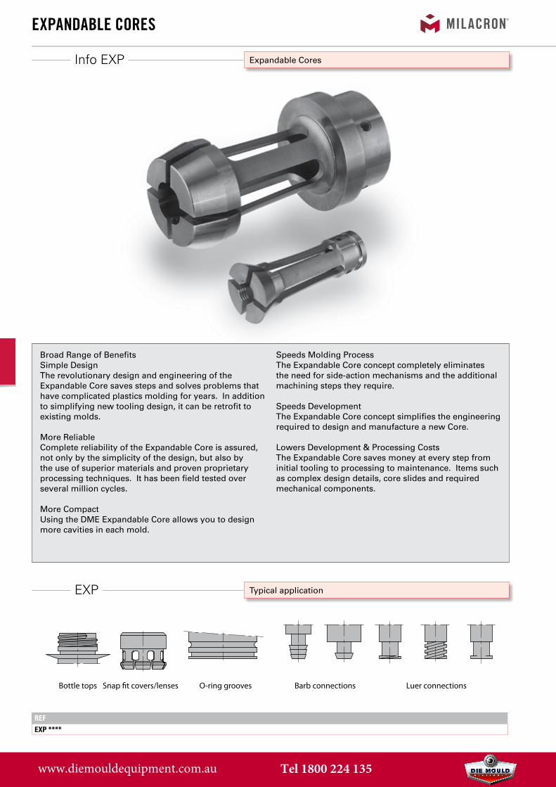
exPandabLe Cores
Bottle tops Snap �t covers/lenses O-ring grooves Barb connections Luer connections
Info EXP Expandable Cores
Typical application
Broad Range of BenefitsSimple DesignThe revolutionary design and engineering of the Expandable Core saves steps and solves problems that have complicated plastics molding for years. In addition to simplifying new tooling design, it can be retrofit to existing molds.
More Reliable Complete reliability of the Expandable Core is assured, not only by the simplicity of the design, but also by the use of superior materials and proven proprietary processing techniques. It has been field tested over several million cycles.
More CompactUsing the DME Expandable Core allows you to design more cavities in each mold.
Speeds Molding ProcessThe Expandable Core concept completely eliminates the need for side-action mechanisms and the additional machining steps they require.
Speeds DevelopmentThe Expandable Core concept simplifies the engineering required to design and manufacture a new Core.
Lowers Development & Processing CostsThe Expandable Core saves money at every step from initial tooling to processing to maintenance. Items such as complex design details, core slides and required mechanical components.
www.diemouldequipment.com.au Tel 1800 224 135
EXP
exPandabLe Cores
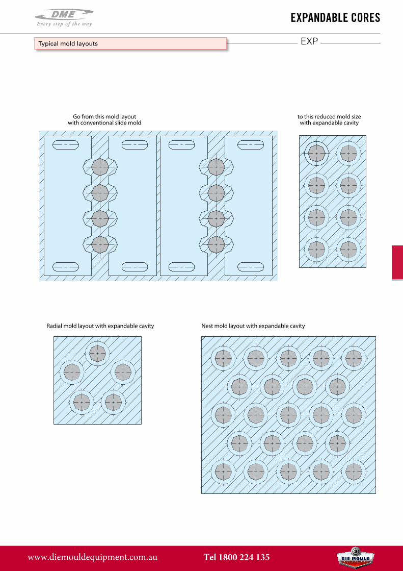
Typical mold layouts
Go from this mold layoutwith conventional slide mold
to this reduced mold sizewith expandable cavity
Radial mold layout with expandable cavity Nest mold layout with expandable cavity
www.diemouldequipment.com.au Tel 1800 224 135
EXP
exPandabLe Cores
Info EXP
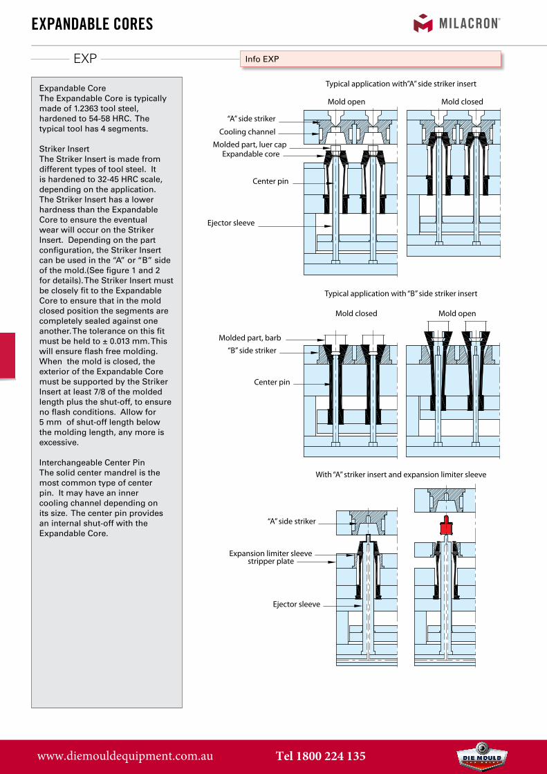
Expandable CoreThe Expandable Core is typically made of 1.2363 tool steel, hardened to 54-58 HRC. The typical tool has 4 segments.
Striker InsertThe Striker Insert is made from different types of tool steel. It is hardened to 32-45 HRC scale, depending on the application. The Striker Insert has a lower hardness than the Expandable Core to ensure the eventual wear will occur on the Striker Insert. Depending on the part configuration, the Striker Insert can be used in the “A” or “B” side of the mold.(See figure 1 and 2 for details). The Striker Insert must be closely fit to the Expandable Core to ensure that in the mold closed position the segments are completely sealed against one another. The tolerance on this fit must be held to ± 0.013 mm. This will ensure flash free molding. When the mold is closed, the exterior of the Expandable Core must be supported by the Striker Insert at least 7/8 of the molded length plus the shut-off, to ensure no flash conditions. Allow for 5 mm of shut-off length below the molding length, any more is excessive.
Interchangeable Center PinThe solid center mandrel is the most common type of center pin. It may have an inner cooling channel depending on its size. The center pin provides an internal shut-off with the Expandable Core.
Typical application with”A” side striker insert
Typical application with “B” side striker insert
With “A” striker insert and expansion limiter sleeve
Mold open
Mold open
Mold closed
Mold closed
“A” side striker
Cooling channel
Molded part, luer capExpandable core
Center pin
Ejector sleeve
“B” side striker
Center pin
Molded part, barb
“A” side striker
Expansion limiter sleevestripper plate
Ejector sleeve
www.diemouldequipment.com.au Tel 1800 224 135
EXP
exPandabLe Cores
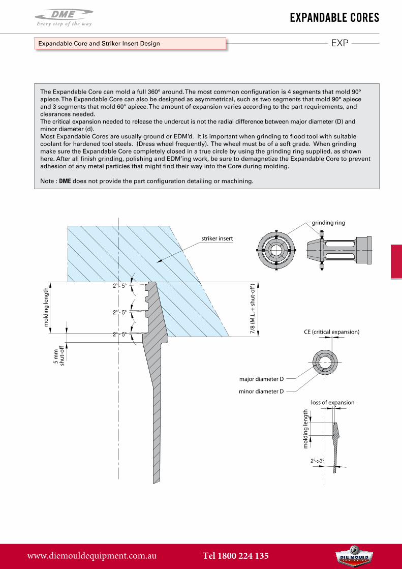
Expandable Core and Striker Insert Design
The Expandable Core can mold a full 360° around. The most common configuration is 4 segments that mold 90° apiece. The Expandable Core can also be designed as asymmetrical, such as two segments that mold 90° apiece and 3 segments that mold 60° apiece. The amount of expansion varies according to the part requirements, and clearances needed.The critical expansion needed to release the undercut is not the radial difference between major diameter (D) and minor diameter (d).Most Expandable Cores are usually ground or EDM’d. It is important when grinding to flood tool with suitable coolant for hardened tool steels. (Dress wheel frequently). The wheel must be of a soft grade. When grinding make sure the Expandable Core completely closed in a true circle by using the grinding ring supplied, as shown here. After all finish grinding, polishing and EDM’ing work, be sure to demagnetize the Expandable Core to prevent adhesion of any metal particles that might find their way into the Core during molding.
Note : DME does not provide the part configuration detailing or machining.
striker insert
major diameter D
minor diameter D
grinding ring
CE (critical expansion)
loss of expansion
mol
ding
leng
th
mol
ding
leng
th
5 m
m
shut
-o�
7/8
(M.L
. + s
hut-
o�)
www.diemouldequipment.com.au Tel 1800 224 135
Info
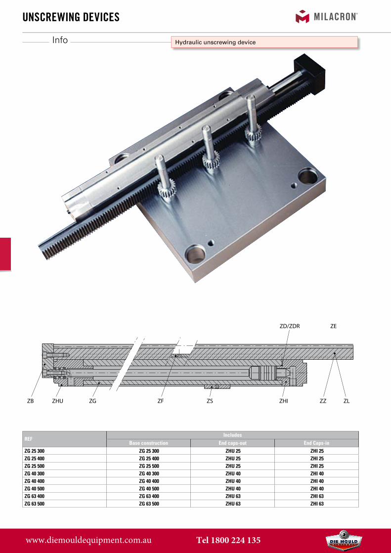
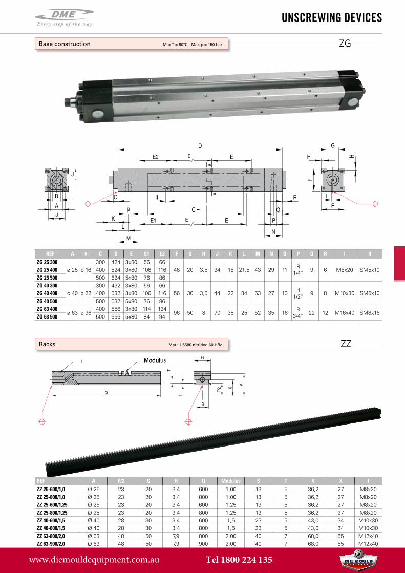
ZB ZHU ZG ZF ZS ZHI ZZ ZL
ZD/ZDR ZE
unsCrewing deViCes
Hydraulic unscrewing device
REFIncludes
Base construction End caps-out End Caps-inZG 25 300 ZG 25 300 ZHU 25 ZHI 25ZG 25 400 ZG 25 400 ZHU 25 ZHI 25ZG 25 500 ZG 25 500 ZHU 25 ZHI 25ZG 40 300 ZG 40 300 ZHU 40 ZHI 40ZG 40 400 ZG 40 400 ZHU 40 ZHI 40ZG 40 500 ZG 40 500 ZHU 40 ZHI 40ZG 63 400 ZG 63 400 ZHU 63 ZHI 63ZG 63 500 ZG 63 500 ZHU 63 ZHI 63
www.diemouldequipment.com.au Tel 1800 224 135
ZG
REF A B C D E E1 E2 F G H J K L M N O P Q R I IIZG 25 300
ø 25 ø 16300 424 3x80 56 66
46 20 3,5 34 18 21,5 43 29 11 R 1/4” 9 6 M8x20 SM5x10ZG 25 400 400 524 3x80 106 116
ZG 25 500 500 624 5x80 76 86ZG 40 300
ø 40 ø 22300 432 3x80 56 66
56 30 3,5 44 22 34 53 27 13 R 1/2” 9 8 M10x30 SM5x10ZG 40 400 400 532 3x80 106 116
ZG 40 500 500 632 5x80 76 86ZG 63 400
ø 63 ø 36400 556 3x80 114 124
96 50 8 70 38 25 52 35 16 R 3/4” 22 12 M16x40 SM8x16
ZG 63 500 500 656 5x80 84 94
ZZ
ModulusModul
unsCrewing deViCes
Base construction Max T = 80°C - Max p = 150 bar
Racks Mat.: 1.6580 nitrided 60 HRc
REF A F/2 G H Q Modulus S T V X IZZ 25-600/1,0 Ø 25 23 20 3,4 600 1,00 13 5 36,2 27 M8x20ZZ 25-800/1,0 Ø 25 23 20 3,4 800 1,00 13 5 36,2 27 M8x20ZZ 25-600/1,25 Ø 25 23 20 3,4 600 1,25 13 5 36,2 27 M8x20ZZ 25-800/1,25 Ø 25 23 20 3,4 800 1,25 13 5 36,2 27 M8x20ZZ 40-600/1,5 Ø 40 28 30 3,4 600 1,5 23 5 43,0 34 M10x30ZZ 40-800/1,5 Ø 40 28 30 3,4 800 1,5 23 5 43,0 34 M10x30ZZ 63-800/2,0 Ø 63 48 50 7,9 800 2,00 40 7 68,0 55 M12x40ZZ 63-900/2,0 Ø 63 48 50 7,9 900 2,00 40 7 68,0 55 M12x40
www.diemouldequipment.com.au Tel 1800 224 135
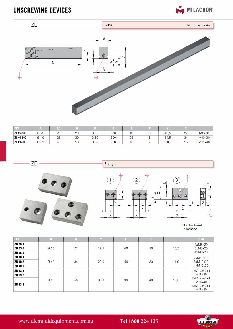
ZB
ZL
REF A F/2 G H Q S T V X IZL 25-800 Ø 25 23 20 3,35 800 13 5 49,5 27 M8x20ZL 40-800 Ø 40 28 30 3,50 800 23 5 64,5 34 M10x30ZL 63-900 Ø 63 48 50 8,00 900 40 7 100,0 55 M12x40
unsCrewing deViCes
Flanges
REF A X Y F Z L I: forZB 25-1
Ø 25 27 12,5 46 20 10,52xM8x203xM8x204xM8x20
ZB 25-2ZB 25-3ZB 40-1
Ø 40 34 20,0 56 30 11,02xM10x303xM10x304xM10x30
ZB 40-2ZB 40-3ZB 63-1
Ø 63 55 30,0 96 40 15,0
1xM12x40+1 M16x40
2xM12x40+1 M16x40
3xM12x40+1 M16x40
ZB 63-2
ZB 63-3
Gibs Mat.: 1.7225 ~30 HRc
1 2 3
* I is the thread dimension
www.diemouldequipment.com.au Tel 1800 224 135
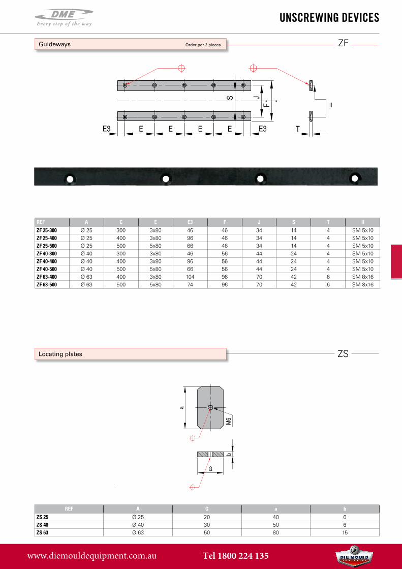
ZF
REF A C E E3 F J S T IIZF 25-300 Ø 25 300 3x80 46 46 34 14 4 SM 5x10ZF 25-400 Ø 25 400 3x80 96 46 34 14 4 SM 5x10ZF 25-500 Ø 25 500 5x80 66 46 34 14 4 SM 5x10ZF 40-300 Ø 40 300 3x80 46 56 44 24 4 SM 5x10ZF 40-400 Ø 40 400 3x80 96 56 44 24 4 SM 5x10ZF 40-500 Ø 40 500 5x80 66 56 44 24 4 SM 5x10ZF 63-400 Ø 63 400 3x80 104 96 70 42 6 SM 8x16ZF 63-500 Ø 63 500 5x80 74 96 70 42 6 SM 8x16
ZS
REF A G a bZS 25 Ø 25 20 40 6ZS 40 Ø 40 30 50 6ZS 63 Ø 63 50 80 15
unsCrewing deViCes
Guideways Order per 2 pieces
Locating plates
www.diemouldequipment.com.au Tel 1800 224 135
11/0
5/20
07
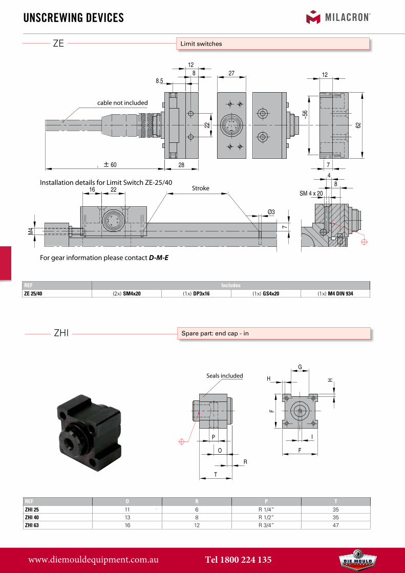
ZE
ZHI
REF O R P TZHI 25 11 6 R 1/4” 35ZHI 40 13 8 R 1/2” 35ZHI 63 16 12 R 3/4” 47
unsCrewing deViCes
Limit switches
±
StrokeInstallation details for Limit Switch ZE-25/40
For gear information please contact D-M-E
cable not included
REF IncludesZE 25/40 (2x) SM4x20 (1x) DP3x16 (1x) GS4x20 (1x) M4 DIN 934
Spare part: end cap - in
Seals included
www.diemouldequipment.com.au Tel 1800 224 135
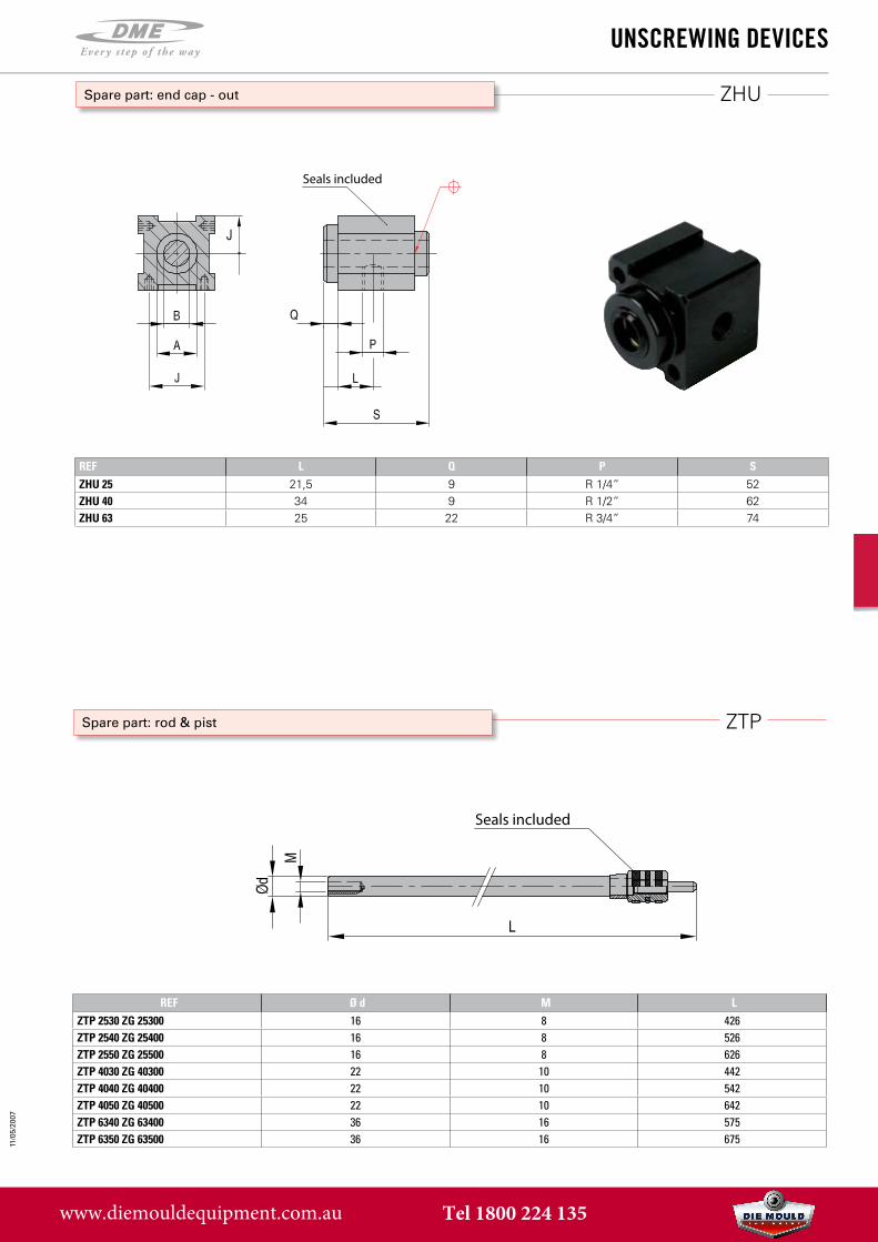
ZHU
REF L Q P SZHU 25 21,5 9 R 1/4” 52ZHU 40 34 9 R 1/2” 62ZHU 63 25 22 R 3/4” 74
11/0
5/20
07
ZTP
REF Ø d M LZTP 2530 ZG 25300 16 8 426ZTP 2540 ZG 25400 16 8 526ZTP 2550 ZG 25500 16 8 626ZTP 4030 ZG 40300 22 10 442ZTP 4040 ZG 40400 22 10 542ZTP 4050 ZG 40500 22 10 642ZTP 6340 ZG 63400 36 16 575ZTP 6350 ZG 63500 36 16 675
unsCrewing deViCes
Spare part: end cap - out
Seals included
Spare part: rod & pist
Seals included
www.diemouldequipment.com.au Tel 1800 224 135
ZDR
ZD
Info
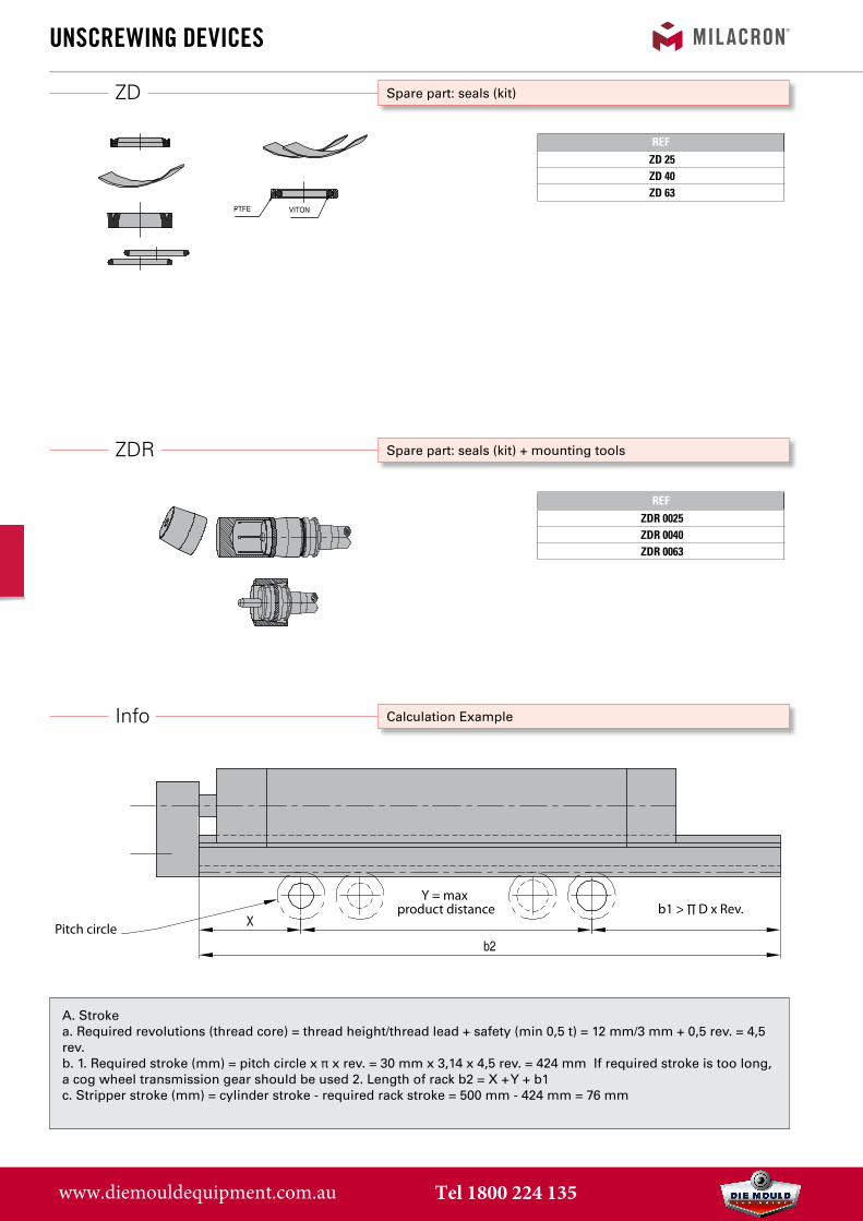
REFZDR 0025ZDR 0040ZDR 0063
REFZD 25ZD 40ZD 63
unsCrewing deViCes
Spare part: seals (kit) + mounting tools
Spare part: seals (kit)
Calculation Example
A. Strokea. Required revolutions (thread core) = thread height/thread lead + safety (min 0,5 t) = 12 mm/3 mm + 0,5 rev. = 4,5rev.b. 1. Required stroke (mm) = pitch circle x π x rev. = 30 mm x 3,14 x 4,5 rev. = 424 mm If required stroke is too long,a cog wheel transmission gear should be used 2. Length of rack b2 = X + Y + b1c. Stripper stroke (mm) = cylinder stroke - required rack stroke = 500 mm - 424 mm = 76 mm
Y = max product distance b1 > ∏ D x Rev.
Pitch circle
www.diemouldequipment.com.au Tel 1800 224 135
Info
unsCrewing deViCes
Calculation Example
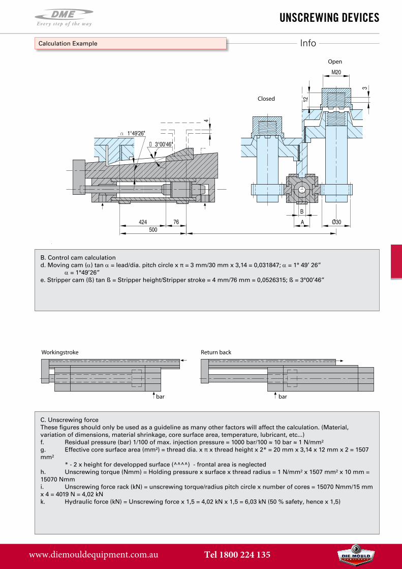
B. Control cam calculationd. Moving cam (α) tan α = lead/dia. pitch circle x π = 3 mm/30 mm x 3,14 = 0,031847; α = 1° 49’ 26”
α = 1°49’26” e. Stripper cam (ß) tan ß = Stripper height/Stripper stroke = 4 mm/76 mm = 0,0526315; ß = 3°00’46”
Closed
Open
C. Unscrewing forceThese figures should only be used as a guideline as many other factors will affect the calculation. (Material,variation of dimensions, material shrinkage, core surface area, temperature, lubricant, etc...)f. Residual pressure (bar) 1/100 of max. injection pressure = 1000 bar/100 ≈ 10 bar ≈ 1 N/mm²g. Effective core surface area (mm²) = thread dia. x π x thread height x 2* = 20 mm x 3,14 x 12 mm x 2 = 1507mm²
* - 2 x height for developped surface (^^^^) - frontal area is neglectedh. Unscrewing torque (Nmm) = Holding pressure x surface x thread radius = 1 N/mm² x 1507 mm² x 10 mm =15070 Nmmi. Unscrewing force rack (kN) = unscrewing torque/radius pitch circle x number of cores = 15070 Nmm/15 mmx 4 = 4019 N = 4,02 kNk. Hydraulic force (kN) = Unscrewing force x 1,5 = 4,02 kN x 1,5 = 6,03 kN (50 % safety, hence x 1,5)
bar bar
Workingstroke Return back
www.diemouldequipment.com.au Tel 1800 224 135
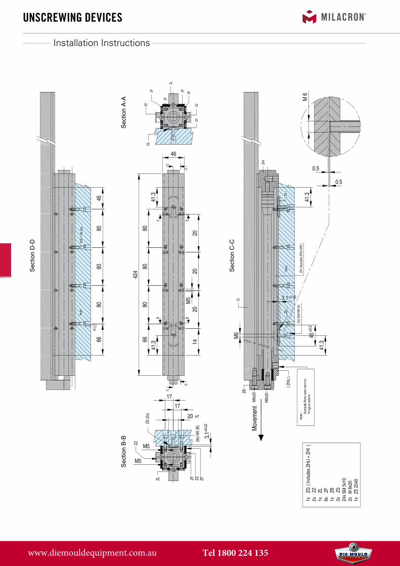
unsCrewing deViCesS
ectio
n D
-D
Sec
tion
B-B
Sec
tion
A-A
Sec
tion
C-C
Installation Instructions
www.diemouldequipment.com.au Tel 1800 224 135
unsCrewing deViCes
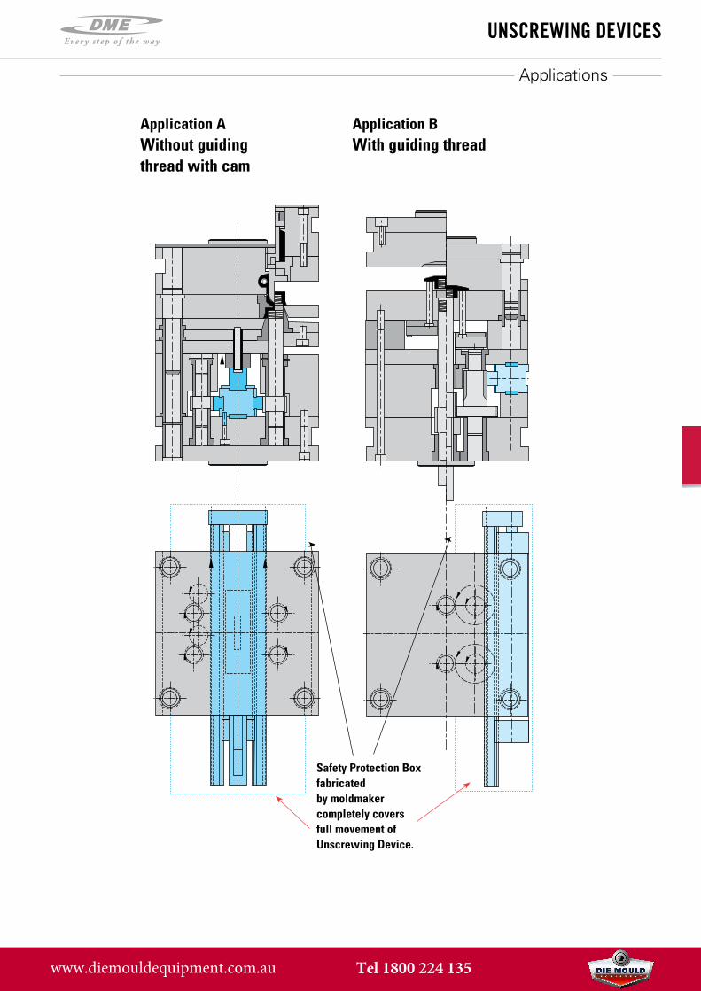
Applications
Application AWithout guiding thread with cam
Application BWith guiding thread
Safety Protection Box fabricated by moldmaker completely covers full movement of Unscrewing Device.
www.diemouldequipment.com.au Tel 1800 224 135
unsCrewing deViCes
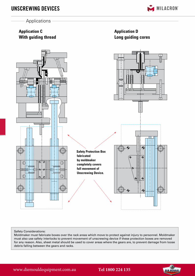
Applications
Application CWith guiding thread
Application DLong guiding cores
Safety Protection Box fabricated by moldmaker completely covers full movement of Unscrewing Device.
Safety Considerations:Moldmaker must fabricate boxes over the rack areas which move to protect against injury to personnel. Moldmaker must also use safety interlocks to prevent movement of unscrewing device if these protection boxes are removed for any reason. Also, sheet metal should be used to cover areas where the gears are, to prevent damage from loose debris falling between the gears and racks.
www.diemouldequipment.com.au Tel 1800 224 135