Embed Size (px)
Citation preview
LatCh LoCks
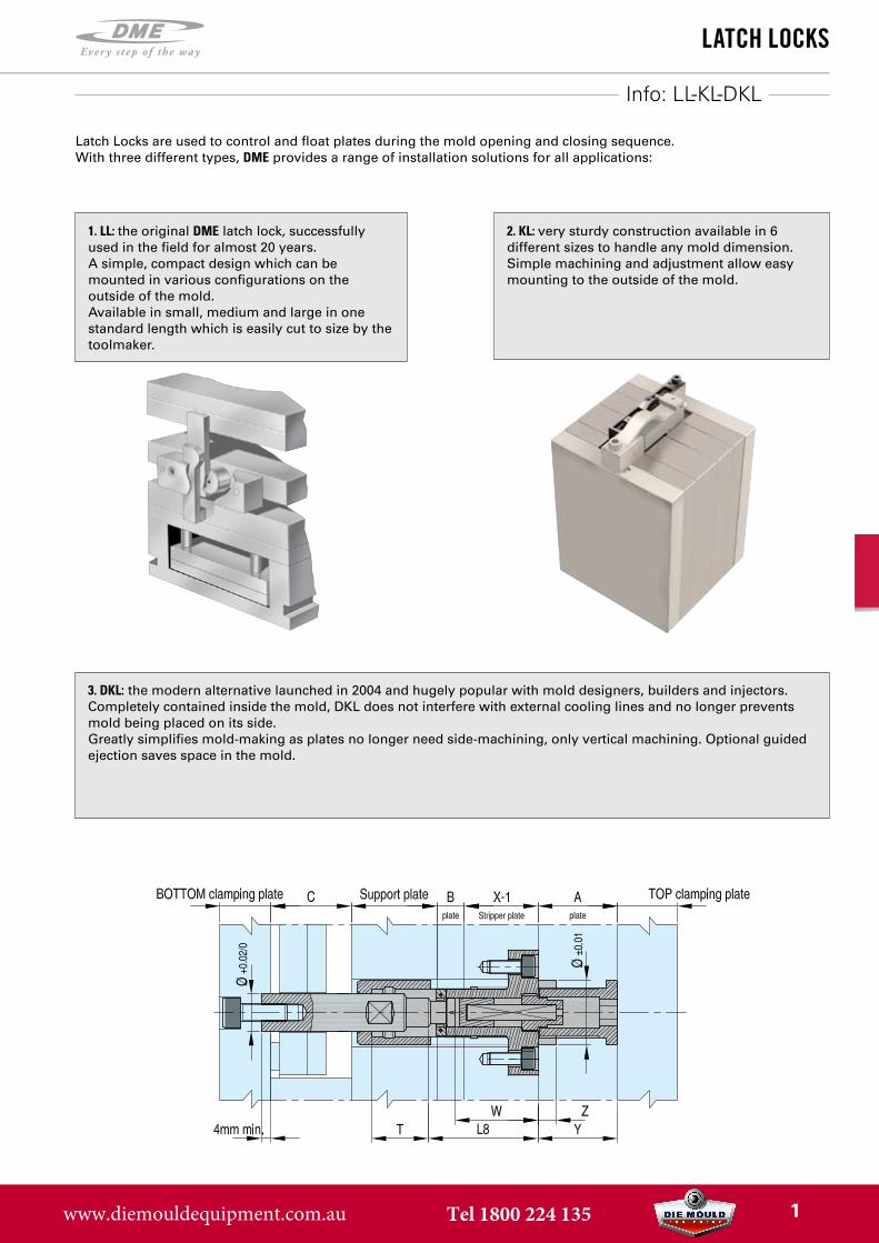
3. DKL: the modern alternative launched in 2004 and hugely popular with mold designers, builders and injectors.Completely contained inside the mold, DKL does not interfere with external cooling lines and no longer preventsmold being placed on its side.Greatly simplifies mold-making as plates no longer need side-machining, only vertical machining. Optional guidedejection saves space in the mold.
2. KL: very sturdy construction available in 6different sizes to handle any mold dimension.Simple machining and adjustment allow easymounting to the outside of the mold.
Info: LL-KL-DKL
Latch Locks are used to control and float plates during the mold opening and closing sequence. With three different types, DME provides a range of installation solutions for all applications:
1. LL: the original DME latch lock, successfullyused in the field for almost 20 years.A simple, compact design which can bemounted in various configurations on theoutside of the mold.Available in small, medium and large in onestandard length which is easily cut to size by thetoolmaker.
www.diemouldequipment.com.au Tel 1800 224 135 1
Info LL
LatCh LoCks
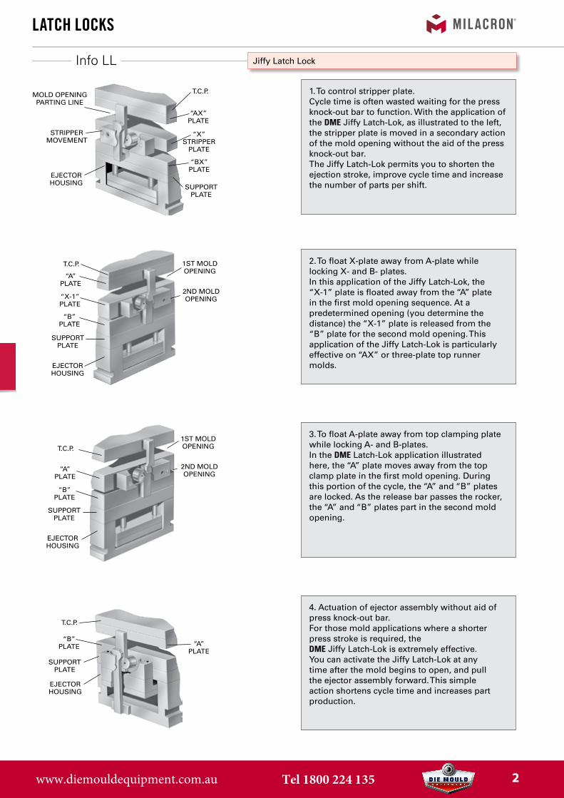
4. Actuation of ejector assembly without aid ofpress knock-out bar.For those mold applications where a shorterpress stroke is required, theDME Jiffy Latch-Lok is extremely effective.You can activate the Jiffy Latch-Lok at anytime after the mold begins to open, and pullthe ejector assembly forward. This simpleaction shortens cycle time and increases partproduction.
3. To float A-plate away from top clamping platewhile locking A- and B-plates.In the DME Latch-Lok application illustratedhere, the “A” plate moves away from the topclamp plate in the first mold opening. Duringthis portion of the cycle, the “A” and “B” platesare locked. As the release bar passes the rocker,the “A” and “B” plates part in the second moldopening.
2. To float X-plate away from A-plate whilelocking X- and B- plates.In this application of the Jiffy Latch-Lok, the“X-1” plate is floated away from the “A” platein the first mold opening sequence. At apredetermined opening (you determine thedistance) the “X-1” plate is released from the“B” plate for the second mold opening. Thisapplication of the Jiffy Latch-Lok is particularlyeffective on “AX” or three-plate top runnermolds.
Jiffy Latch Lock
1. To control stripper plate.Cycle time is often wasted waiting for the pressknock-out bar to function. With the application ofthe DME Jiffy Latch-Lok, as illustrated to the left,the stripper plate is moved in a secondary actionof the mold opening without the aid of the pressknock-out bar.The Jiffy Latch-Lok permits you to shorten theejection stroke, improve cycle time and increasethe number of parts per shift.
MOLD OPENINGPARTING LINE
STRIPPERMOVEMENT
EJECTORHOUSING
T.C.P.
“AX”PLATE
“BX”PLATE
SUPPORTPLATE
1ST MOLDOPENING
2ND MOLDOPENING
EJECTORHOUSING
SUPPORTPLATE
T.C.P.
“A”PLATE
“X-1”PLATE
“B”PLATE
EJECTORHOUSING
SUPPORTPLATE
T.C.P.
“B”PLATE “A”
PLATE
1ST MOLDOPENING
2ND MOLDOPENING
EJECTORHOUSING
SUPPORTPLATE
T.C.P.
“A”PLATE
“B”PLATE
“X”STRIPPER
PLATE
www.diemouldequipment.com.au Tel 1800 224 135 2
LL
LL
LL
LL
LL
LatCh LoCks
Spacer
Release bar
Latch bar
Body
Jiffy Latch Lock
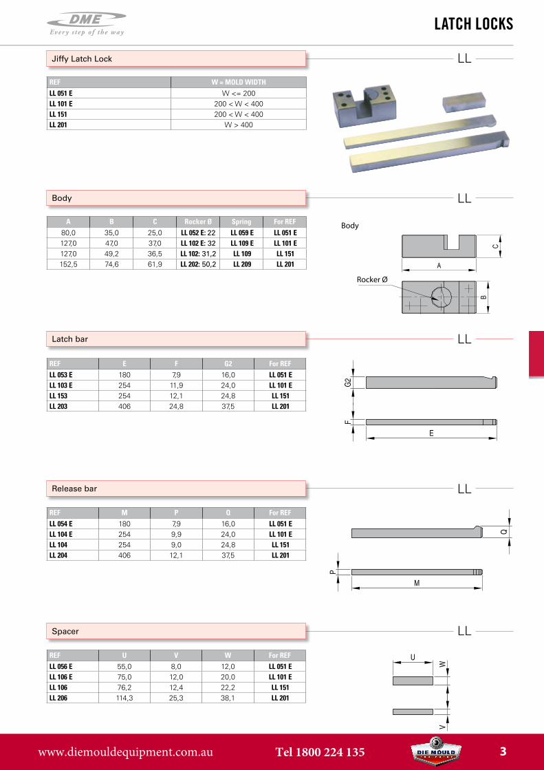
REF W = MOLD WIDTHLL 051 E W <= 200LL 101 E 200 < W < 400LL 151 200 < W < 400LL 201 W > 400
A B C Rocker Ø Spring For REF80,0 35,0 25,0 LL 052 E: 22 LL 059 E LL 051 E127,0 47,0 37,0 LL 102 E: 32 LL 109 E LL 101 E127,0 49,2 36,5 LL 102: 31,2 LL 109 LL 151152,5 74,6 61,9 LL 202: 50,2 LL 209 LL 201
REF E F G2 For REFLL 053 E 180 7,9 16,0 LL 051 ELL 103 E 254 11,9 24,0 LL 101 ELL 153 254 12,1 24,8 LL 151LL 203 406 24,8 37,5 LL 201
REF M P Q For REFLL 054 E 180 7,9 16,0 LL 051 ELL 104 E 254 9,9 24,0 LL 101 ELL 104 254 9,0 24,8 LL 151LL 204 406 12,1 37,5 LL 201
REF U V W For REFLL 056 E 55,0 8,0 12,0 LL 051 ELL 106 E 75,0 12,0 20,0 LL 101 ELL 106 76,2 12,4 22,2 LL 151LL 206 114,3 25,3 38,1 LL 201
Body
Rocker Ø
www.diemouldequipment.com.au Tel 1800 224 135 3
Jiffy
LatCh LoCks
Installation instructions LL-051 / LL-101 / LL-201
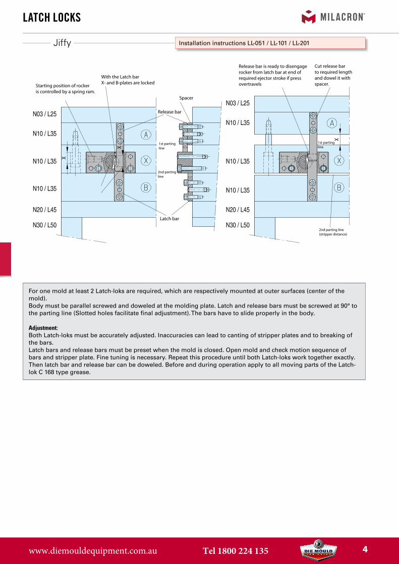
For one mold at least 2 Latch-loks are required, which are respectively mounted at outer surfaces (center of the mold). Body must be parallel screwed and doweled at the molding plate. Latch and release bars must be screwed at 90° to the parting line (Slotted holes facilitate final adjustment). The bars have to slide properly in the body.
Adjustment:Both Latch-loks must be accurately adjusted. Inaccuracies can lead to canting of stripper plates and to breaking of the bars.Latch bars and release bars must be preset when the mold is closed. Open mold and check motion sequence of bars and stripper plate. Fine tuning is necessary. Repeat this procedure until both Latch-loks work together exactly. Then latch bar and release bar can be doweled. Before and during operation apply to all moving parts of the Latch-lok C 168 type grease.
Starting position of rockeris controlled by a spring ram.
With the Latch barX- and B-plates are locked
Spacer
Release bar
Latch bar
1st parting line
2nd partingline
Release bar is ready to disengagerocker from latch bar at end of required ejector stroke if pressovertravels
Cut release bar to required length and dowel it with spacer.
1st parting line
2nd parting line(stripper distance)
www.diemouldequipment.com.au Tel 1800 224 135 4
Jiffy
LatCh LoCks
Installation instructions LL-151
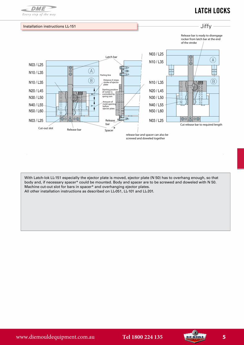
With Latch-lok LL-151 especially the ejector plate is moved, ejector plate (N 50) has to overhang enough, so that body and, if necessary spacer* could be mounted. Body and spacer are to be screwed and doweled with N 50.Machine cut-out slot for bars in spacer* and overhanging ejector plates. All other installation instructions as described on LL-051, LL-101 and LL-201.
Cut-out slotSpacer
Release bar
Latch bar
Parting line
Distance X stopsstroke of ejectorplate
Release bar is ready to disengagerocker from latch bar at the end of the stroke
Cut release bar to required length
Release bar
Starting positionof rocker iscontrolled by spring ram
Amount ofmold openingbeforeejector plate.
release bar and spacer can also bescrewed and doweled together
*
www.diemouldequipment.com.au Tel 1800 224 135 5
LatCh LoCks
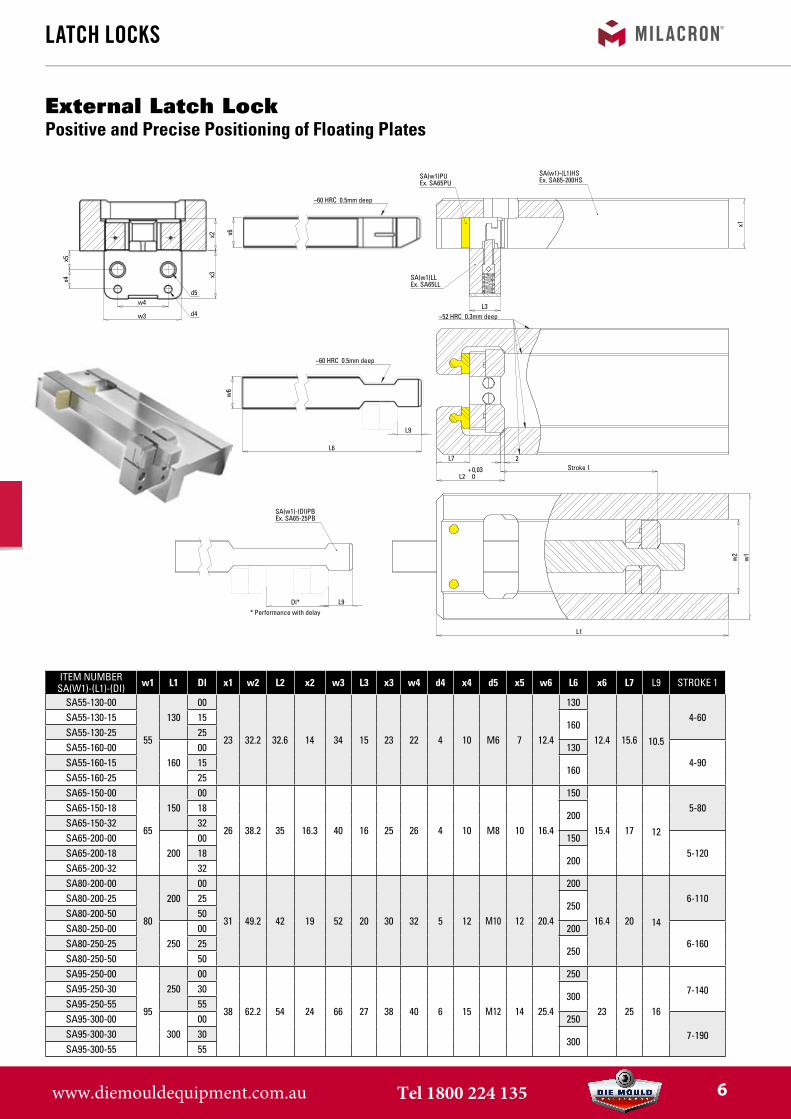
External Latch LockPositive and Precise Positioning of Floating Plates
x5x4
w4
w3
x3x2
d5
d4
x6
~60 HRC 0.5mm deep
L7
L2 +0,03
0
2Stroke 1
~52 HRC 0.3mm deep
x1
L3
SA(w1)PUEx. SA65PU
SA(w1)LLEx. SA65LL
SA(w1)-(L1)HSEx. SA65-200HS
w6
L6
L9
~60 HRC 0.5mm deep
L9Dl*
SA(w1)-(Dl)PBEx. SA65-25PB
* Performance with delay
w1
w2
L1
item numbersa(w1)-(L1)-(Di) w1 L1 Dl x1 w2 L2 x2 w3 L3 x3 w4 d4 x4 d5 x5 w6 L6 x6 L7 L9 stroke 1
sa55-130-00
55
13000
23 32.2 32.6 14 34 15 23 22 4 10 m6 7 12.4
130
12.4 15.6 10.5
4-60sa55-130-15 15160
sa55-130-25 25sa55-160-00
16000 130
4-90sa55-160-15 15160
sa55-160-25 25sa65-150-00
65
15000
26 38.2 35 16.3 40 16 25 26 4 10 m8 10 16.4
150
15.4 17 12
5-80sa65-150-18 18200
sa65-150-32 32sa65-200-00
20000 150
5-120sa65-200-18 18200
sa65-200-32 32sa80-200-00
80
20000
31 49.2 42 19 52 20 30 32 5 12 m10 12 20.4
200
16.4 20 14
6-110sa80-200-25 25250
sa80-200-50 50sa80-250-00
25000 200
6-160sa80-250-25 25250
sa80-250-50 50sa95-250-00
95
25000
38 62.2 54 24 66 27 38 40 6 15 m12 14 25.4
250
23 25 16
7-140sa95-250-30 30300
sa95-250-55 55sa95-300-00
30000 250
7-190sa95-300-30 30300
sa95-300-55 55
www.diemouldequipment.com.au Tel 1800 224 135 6
LatCh LoCks
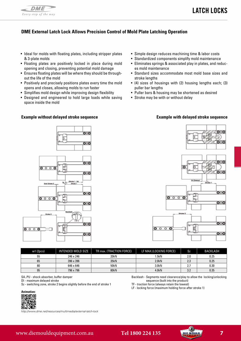
Example without delayed stroke sequence Example with delayed stroke sequence
w1 (2pcs) intenDeD moLD siZe tr max. (traCtion ForCe) LF maX.(LoCkinG ForCe) sz baCkLasH
55 246 x 246 20kn 1.5kn 2.0 0.2565 396 x 396 35kn 2.0kn 2.3 0.2580 646 x 646 50kn 3.0kn 2.7 0.3095 796 x 796 80kn 4.0kn 3.2 0.35
Backlash - Segments need clearance/play to allow the locking/unlocking sequence (built into the product)
TF - traction force (always retain the lowest)LF - locking force (maximum holding force after stroke 1)
SA..PU - shock absorber, buffer damperDI - maximum delayed strokeSz - switching zone, stroke 2 begins slightly before the end of stroke 1
http://www.dme.net/resources/multimedia/external-latch-lock
Animation:
DME External Latch Lock Allows Precision Control of Mold Plate Latching Operation
• Ideal for molds with floating plates, including stripper plates& 3-plate molds
• Floating plates are positively locked in place during moldopening and closing, preventing potential mold damage
• Ensures floating plates will be where they should be through-out the life of the mold
• Positively and precisely positions plates every time the moldopens and closes, allowing molds to run faster
• Simplifies mold design while improving design flexibility• Designed and engineered to hold large loads while saving
space inside the mold
• Simple design reduces machining time & labor costs• Standardized components simplify mold maintenance• Eliminates springs & associated play in plates, and reduc-
es mold maintenance• Standard sizes accommodate most mold base sizes and
stroke lengths• (4) sizes of housings with (2) housing lengths each; (3)
puller bar lengths• Puller bars & housing may be shortened as desired• Stroke may be with or without delay
www.diemouldequipment.com.au Tel 1800 224 135 7

KL
KL1/1/1
KL/1/2
KL/1/3
KU1/1
KU/1/2KL2/2 KU/2/2
LatCh LoCks
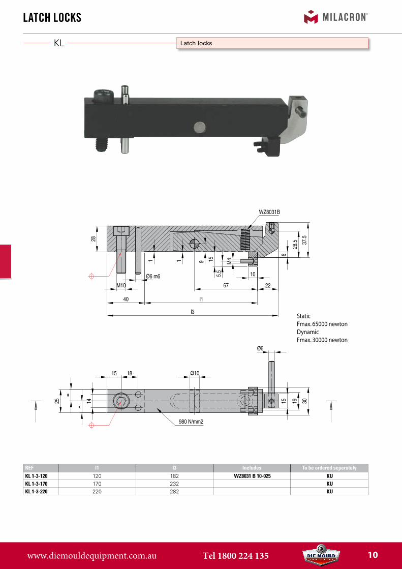
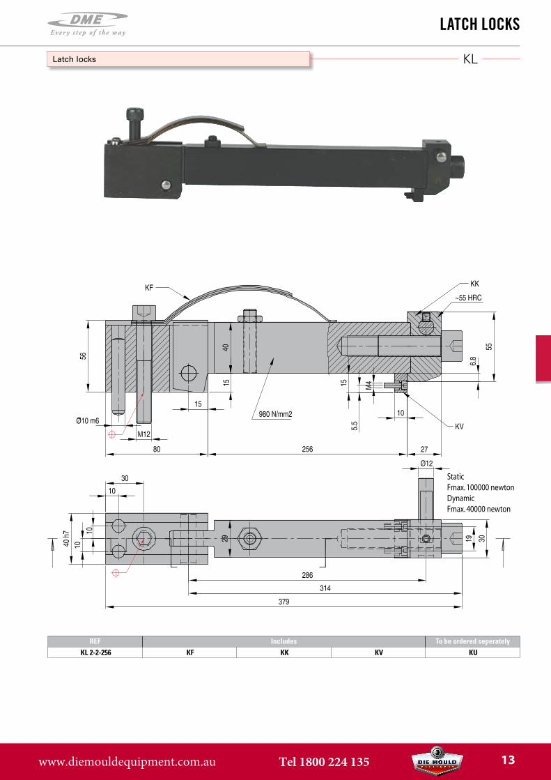
Latch locks
Number of Combinations
StaticFmax. 40000 newtonDynamicFmax. 16000 newton
REF Includes To be ordered seperatelyKL1-1-70 KF KK KV KU
www.diemouldequipment.com.au Tel 1800 224 135 8

KL
LatCh LoCks
Latch locks
StaticFmax. 40000 newtonDynamicFmax. 16000 newton
REF L La Lb l1 Includes To be ordered seperatelyKL 1-2-90 90 117 137 172 KF/KK/KV KUKL 1-2-170 170 197 217 252 KF/KK/KV KUKL 1-2-220 220 247 267 302 KF/KK/KV KUKL 1-2-270 270 297 317 352 KF/KK/KV KU
www.diemouldequipment.com.au Tel 1800 224 135 9
KL
LatCh LoCks
Latch locks
StaticFmax. 65000 newtonDynamicFmax. 30000 newton
REF l1 l3 Includes To be ordered seperatelyKL 1-3-120 120 182 WZ8031 B 10-025 KUKL 1-3-170 170 232 KUKL 1-3-220 220 282 KU
www.diemouldequipment.com.au Tel 1800 224 135 10
KU
LatCh LoCks
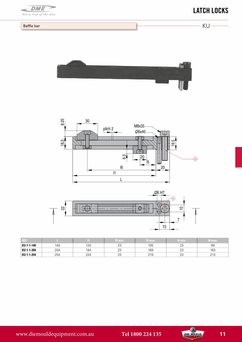
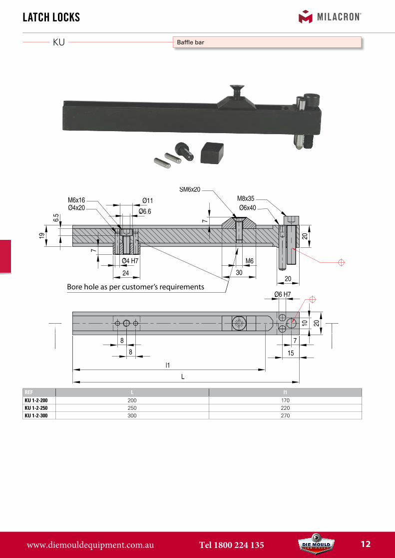
Baffle bar
REF L l1 l5 min. l5 max. l6 min. l6 max.KU 1-1-140 140 120 23 105 23 99KU 1-1-204 204 184 23 169 23 163KU 1-1-254 254 234 23 219 23 213
www.diemouldequipment.com.au Tel 1800 224 135 11
KU
REF L l1KU 1-2-200 200 170KU 1-2-250 250 220KU 1-2-300 300 270
LatCh LoCks
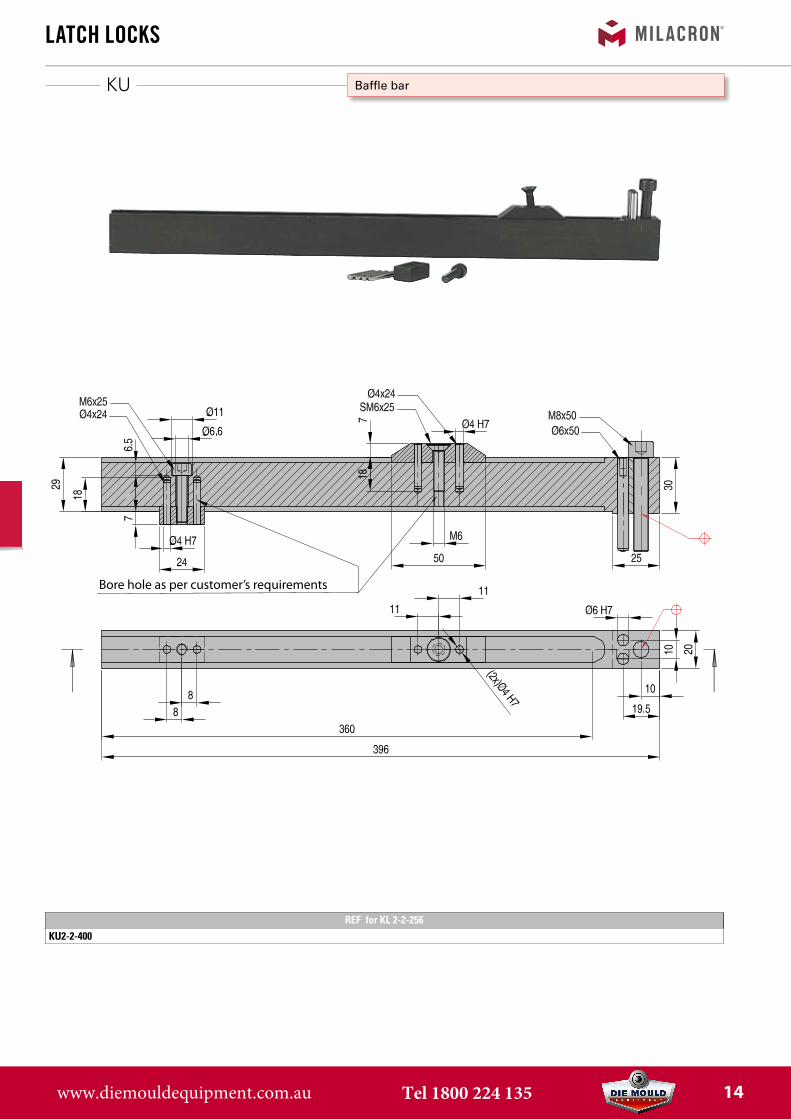
Baffle bar
Bore hole as per customer’s requirements
www.diemouldequipment.com.au Tel 1800 224 135 12
KL
LatCh LoCks
Latch locks
15
StaticFmax. 100000 newtonDynamicFmax. 40000 newton
REF Includes To be ordered seperatelyKL 2-2-256 KF KK KV KU
www.diemouldequipment.com.au Tel 1800 224 135 13
KU
LatCh LoCks
Baffle bar
Bore hole as per customer’s requirements
REF for KL 2-2-256KU2-2-400
www.diemouldequipment.com.au Tel 1800 224 135 14

WZ 8031
KV
KK
KF
REF A A1 A2 M D B C
KK 11-12 37,5 23,6 21 157 6 27 20
KK 22 55 40 26,95 157 12 30 27
LatCh LoCks
Springs
Wearing bars
Heads
Springs
KK 11-12 for latch lock KL1-1-70 / KL1-2-170 / KL1-2-220 / KL1-2-270KK 22 for latch lock KL2-2-256
REF
KV 11-12 FOR ALL KL
REF
WZ 8031 B 10-25 FOR ALL KL 1-3-*
REF PART A PART B B L1 L FOR LATCH LOCK
KF 12-70 2x 1x 20 90 110 KL 1-1-70
KF 12-90 2x 1x 20 90 110 KL 1-2-90
KF 12-170 2x 1x 20 90 110 KL 1-2-170
KF 12-220-270 2x 1x 20 127 157 KL 1-2-220 - 270
KF 22-256 2x 1x 25 127 157 KL 2-2-256
www.diemouldequipment.com.au Tel 1800 224 135 15
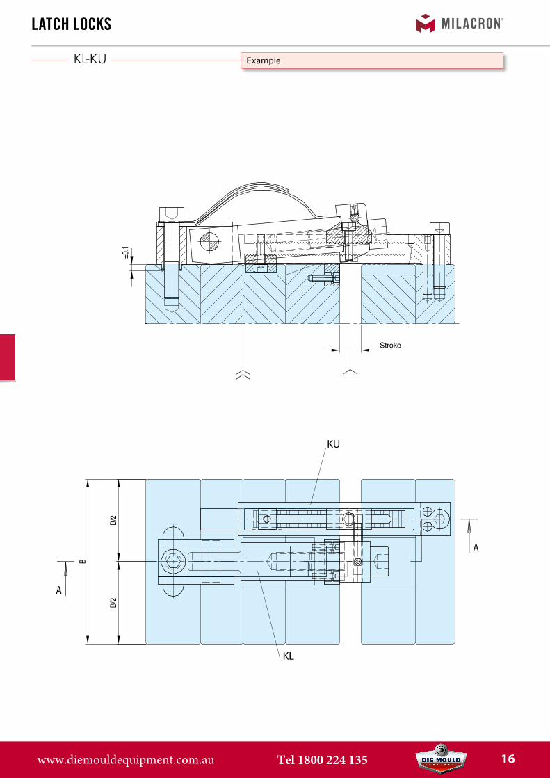
KL-KU
KU
KL
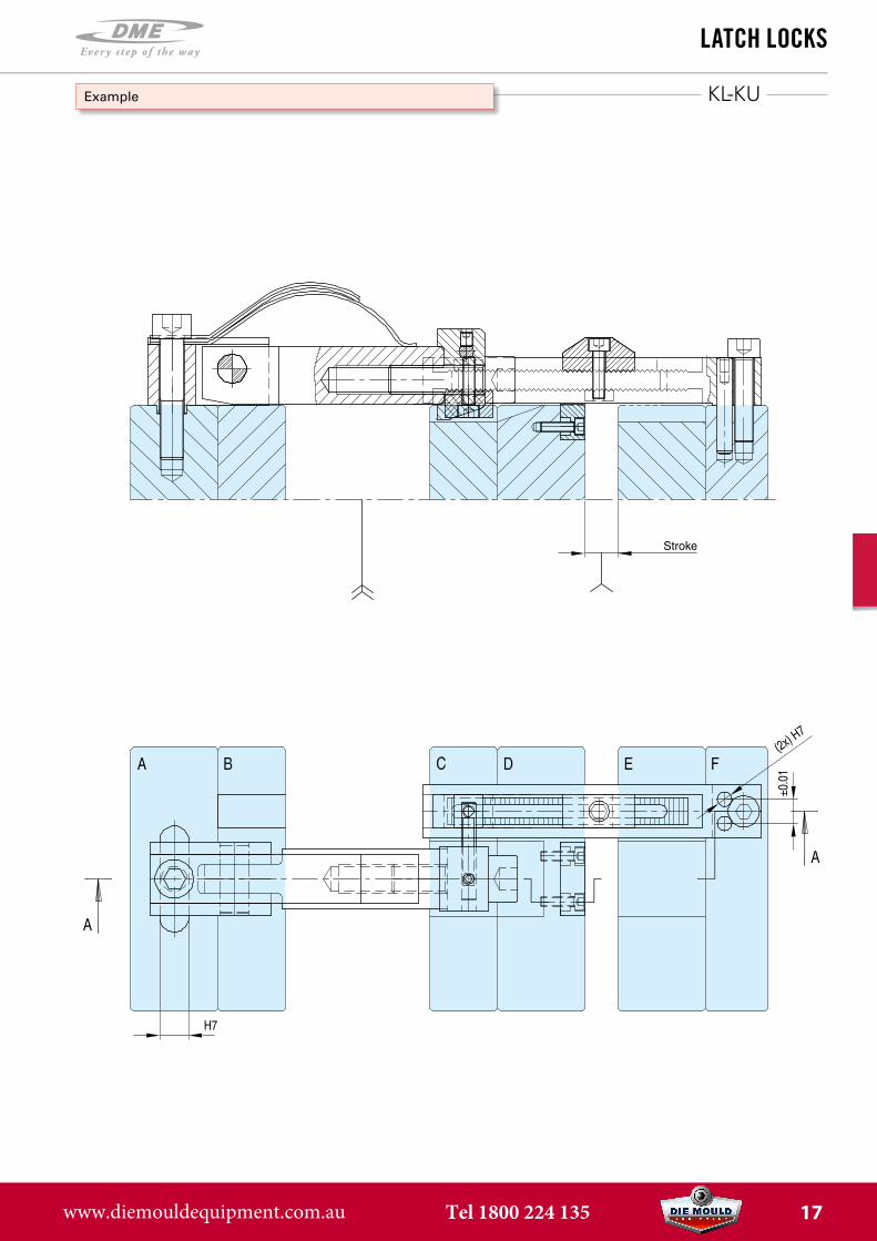
Stroke
LatCh LoCks
Example
www.diemouldequipment.com.au Tel 1800 224 135 16
KL-KU
Stroke
LatCh LoCks
Example
www.diemouldequipment.com.au Tel 1800 224 135 17
DKL
LatCh LoCks
Internal Latch Lock
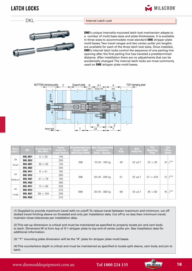
DME’s unique internally-mounted latch lock mechanism adapts to a number of mold base sizes and plate thicknesses. It is available in three sizes to accommodate most standard DME stripper plate mold bases. Two travel ranges and two center puller pin lengths are available for each of the three latch lock sizes. Once installed, DME’s internal latch locks control the sequence of one parting line opening after the first parting line has traveled a predetermined distance. After installation there are no adjustments that can be accidentally changed. The internal latch locks are most commonly used on DME stripper plate mold bases.
BasicLatch ∅ REF Travel Range (1)
Min./Max.Center
Puller PinLength Options
Recommended max.Standard DME
Mold Base Width
Max. RecommendedLoad Values
Static - DynamicL8
BodyW(2)
Puller PinY(3)
Mounting Plate
Z(4)C’BareDepth
28
Small
DKL 2811 5 -> 30 140
296 10 kN - 100 kg 40 23 ±0,1 22 -> 35 10 +0,040
DKL 2812 250DKL 2821 30 -> 55 140DKL 2822 250
34
Medium
DKL 3411 6 -> 41 160
396 20 kN - 200 kg 51 32 ±0,1 27 -> 47,6 12 +0,040
DKL 3412 280DKL 3421 41 -> 76 160DKL 3422 280
45
Large
DKL 4511 12 -> 58 200
596 30 kN - 380 kg 68 43 ±0,1 35 -> 60 16 +0,040
DKL 4512 310DKL 4521 58 -> 104 200DKL 4522 310
(1) Supplied to provide maximum travel with no cutoff. To reduce travel between maximum and minimum, cut offslotted travel limiting sleeve on threaded end only per installation data. Cut off to no less than minimum travel;maintain close tolerances per installation data.
(2) This set-up dimension is critical and must be maintained as specified to properly locate pin and cam bodyto latch. Dimension W is from top of X-1 stripper plate to top end of center puller pin. See installation data foradditional information.
(3) “Y” mounting plate dimension will be the “A” plate for stripper plate mold bases.
(4) This counterbore depth is critical and must be maintained as specified to locate split sleeve, cam body and pin tolatch.
www.diemouldequipment.com.au Tel 1800 224 135 18
4 mmMin.
DKL
4 mmMin.
LatCh LoCks
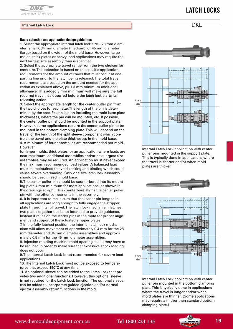
Basic selection and application design guidelines1. Select the appropriate internal latch lock size – 28 mm diam-eter (small), 34 mm diameter (medium), or 45 mm diameter(large) based on the width of the mold base. However, largemolds, thick plates or heavy load applications may require thenext largest size assembly than is specified.2. Select the appropriate travel range from the two choices foreach size. This selection is based on the specific applicationrequirements for the amount of travel that must occur at oneparting line prior to the latch being released. The total travelrequirements are based on the amount needed for the appli-cation as explained above, plus 3 mm minimum additionalallowance. This added 3 mm minimum will make sure the fullrequired travel has occurred before the latch lock starts itsreleasing action.3. Select the appropriate length for the center puller pin fromthe two choices for each size. The length of the pin is deter-mined by the specific application including the mold base platethicknesses, where the pin will be mounted, etc. If possible,the center puller pin should be mounted in the support plate.However, some applications require the center puller pin to bemounted in the bottom clamping plate. This will depend on thetravel or the length of the split sleeve component which con-trols the travel and the plate thicknesses in the mold base.4. A minimum of four assemblies are recommended per mold.However,for larger molds, thick plates, or an application where loads arenear maximum, additional assemblies and/or next largest sizeassemblies may be required. An application must never exceedthe maximum recommended load values. A balanced loadmust be maintained to avoid cocking and binding which couldcause severe overloading. Only one size latch lock assemblyshould be used in each mold base.5. The center puller pin should be counterbored into its mount-ing plate 4 mm minimum for most applications, as shown inthe drawings at right. This counterbore aligns the center pullerpin with the other components in the assembly.6. It is important to make sure that the leader pin lengths inall applications are long enough to fully engage the stripperplate through its full travel. The latch lock mechanism latchestwo plates together but is not intended to provide guidance.Instead it relies on the leader pins in the mold for proper align-ment and support of the actuated stripper plates.7. In the fully latched position the internal latch lock mecha-nism will allow movement of approximately 0.4 mm for the 28mm diameter and 34 mm diameter assemblies and approxi-mately 0.5 mm for the 45 mm diameter assemblies.8. Injection molding machine mold opening speed may have tobe reduced in order to make sure that excessive shock loadingdoes not occur.9. The Internal Latch Lock is not recommended for severe loadapplications.10. The Internal Latch Lock must not be exposed to tempera-tures that exceed 150°C at any time.11. An optional sleeve can be added to the Latch Lock that pro-vides two additional functions. However, this optional sleeveis not required for the Latch Lock function. The optional sleevecan be added to incorporate guided ejection and/or normalejector assembly return functions in the mold.
Internal Latch Lock
Internal Latch Lock application with center puller pins mounted in the support plate. This is typically done in applications where the travel is shorter and/or when mold plates are thicker.
Internal Latch Lock application with center puller pin mounted in the bottom clamping plate. This is typically done in applications where the travel is longer and/or when mold plates are thinner. (Some applications may require a thicker than standard bottom clamping plate.)
www.diemouldequipment.com.au Tel 1800 224 135 19
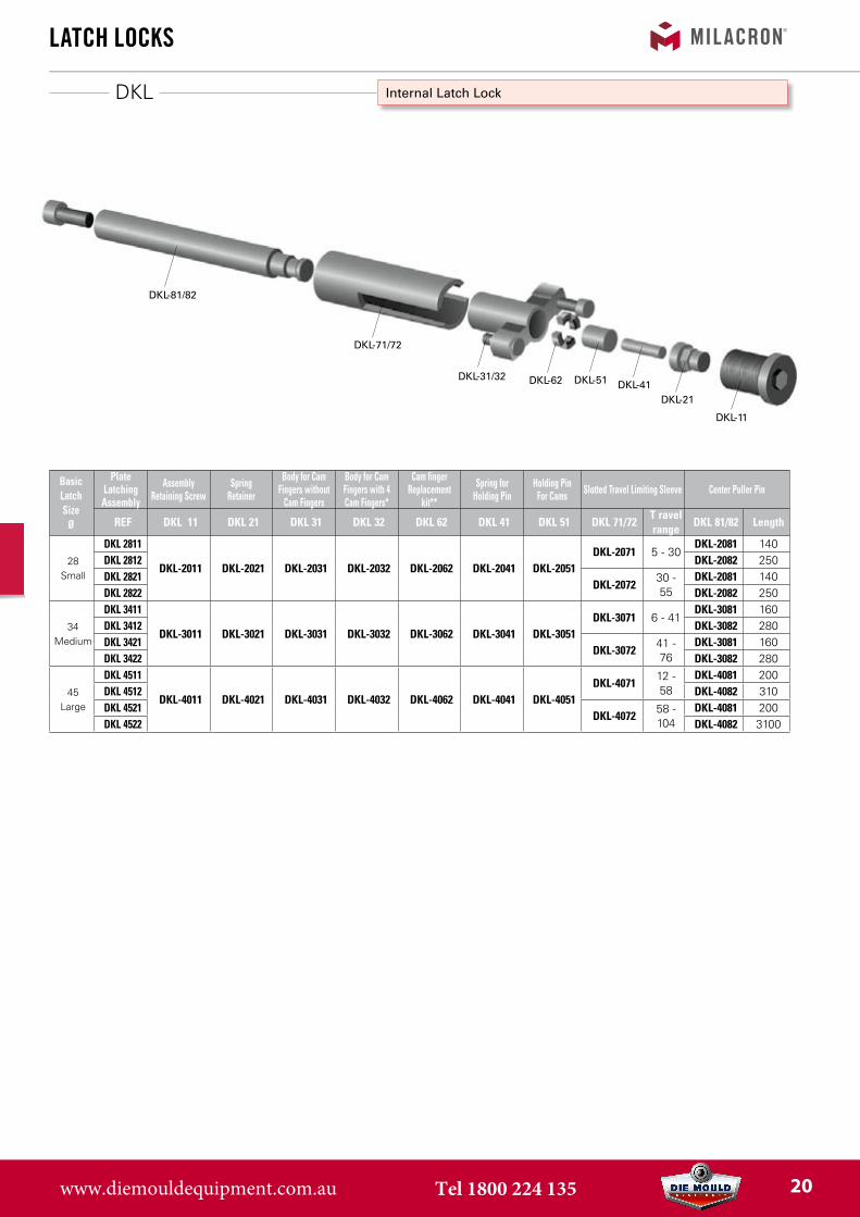
DKL-81/82
DKL-71/72
DKL-31/32 DKL-62 DKL-51 DKL-41DKL-21
DKL-11
DKL
LatCh LoCks
Internal Latch Lock
BasicLatch Size
Ø
PlateLatchingAssembly
AssemblyRetaining Screw
Spring Retainer
Body for Cam Fingers without
Cam Fingers
Body for Cam Fingers with 4 Cam Fingers*
Cam fingerReplacement
kit**
Spring forHolding Pin
Holding PinFor Cams Slotted Travel Limiting Sleeve Center Puller Pin
REF DKL 11 DKL 21 DKL 31 DKL 32 DKL 62 DKL 41 DKL 51 DKL 71/72T ravel range
DKL 81/82 Length
28Small
DKL 2811
DKL-2011 DKL-2021 DKL-2031 DKL-2032 DKL-2062 DKL-2041 DKL-2051DKL-2071 5 - 30
DKL-2081 140DKL 2812 DKL-2082 250DKL 2821
DKL-207230 - 55
DKL-2081 140DKL 2822 DKL-2082 250
34Medium
DKL 3411
DKL-3011 DKL-3021 DKL-3031 DKL-3032 DKL-3062 DKL-3041 DKL-3051DKL-3071 6 - 41
DKL-3081 160DKL 3412 DKL-3082 280DKL 3421
DKL-307241 - 76
DKL-3081 160DKL 3422 DKL-3082 280
45Large
DKL 4511
DKL-4011 DKL-4021 DKL-4031 DKL-4032 DKL-4062 DKL-4041 DKL-4051DKL-4071
12 - 58
DKL-4081 200DKL 4512 DKL-4082 310DKL 4521
DKL-407258 - 104
DKL-4081 200DKL 4522 DKL-4082 3100
www.diemouldequipment.com.au Tel 1800 224 135 20
DKL21
DKL51
DKL41
Ø D
15
DKL11
LatCh LoCks
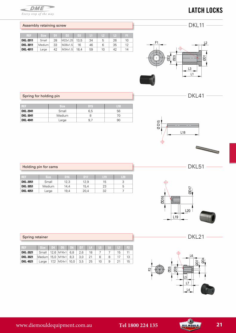
Spring retainer
Holding pin for cams
Spring for holding pin
Assembly retaining screw
REF Size D1 D2 D3 L1 L2 L3 F1DKL-2011 Small 28 M22x1,25 13,5 34 5 26 10DKL-3011 Medium 33 M26x1,5 16 46 6 35 12DKL-4011 Large 42 M34x1,5 18,4 59 10 42 14
REF Size D15 L18DKL-2041 Small 6,5 56DKL-3041 Medium 8 70DKL-4041 Large 9,7 90
REF Size D16 D17 L19 L20DKL-2051 Small 12,3 12,9 15 3DKL-3051 Medium 14,4 15,4 23 5DKL-4051 Large 19,4 20,4 32 7
REF Size D4 D5 D6 D7 L4 L5 L6 L7 F2DKL-2021 Small 12,6 M16x1 6,8 2,6 18 7 7 15 11DKL-3021 Medium 15,0 M19x1 8,3 3,0 21 8 8 17 13DKL-4021 Large 17,2 M24x1 10,0 3,5 25 10 9 21 15
www.diemouldequipment.com.au Tel 1800 224 135 21

DKL32
R1
DKL32
R1
DKL62
LatCh LoCks
Body for cam fingers - with cam fingers
Body for cam fingers - with cam fingers
Cam finger replacement kit
D13
REF Size D8 D9 D10 L8 L9 L12 L14 L15 R1 Drill Ø C’bore Ø C’bore depth Metric S.H.C.S.
DKL-2032 Small 54 20,6 M16x1 40 13 7 40 12,6 2,5 6,8 10,4 6,8 M6x1
D13REF Size D8 D9 D10 L8 L9 L12 L14 L15 R1 Drill Ø C’bore Ø C’bore depth Metric S.H.C.S.DKL-3032 Medium 60 24,4 M19x1 51 15 8 46 12,6 2,5 6,8 10,4 6,8 M6x1DKL-4032 Large 78 32,4 M24x1 68 20 10 60 17 4 8,4 13,7 8,5 M8x1,25
REF Size L16 L17DKL-2062 Small 5,8 4,2DKL-3062 Medium 7,2 4,8DKL-4062 Large 9 6,0
www.diemouldequipment.com.au Tel 1800 224 135 22
DKL81/82
DKL71/72
LatCh LoCks
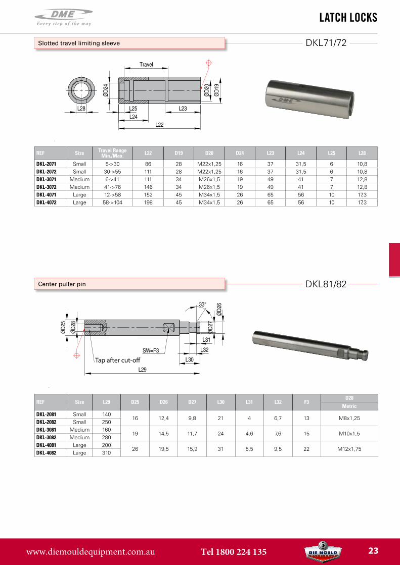
Center puller pin
Tap after cut-o�
Slotted travel limiting sleeve
REF Size Travel Range Min./Max. L22 D19 D20 D24 L23 L24 L25 L28
DKL-2071 Small 5->30 86 28 M22x1,25 16 37 31,5 6 10,8DKL-2072 Small 30->55 111 28 M22x1,25 16 37 31,5 6 10,8DKL-3071 Medium 6->41 111 34 M26x1,5 19 49 41 7 12,8DKL-3072 Medium 41->76 146 34 M26x1,5 19 49 41 7 12,8DKL-4071 Large 12->58 152 45 M34x1,5 26 65 56 10 17,3DKL-4072 Large 58->104 198 45 M34x1,5 26 65 56 10 17,3
REF Size L29 D25 D26 D27 L30 L31 L32 F3D28
MetricDKL-2081 Small 140
16 12,4 9,8 21 4 6,7 13 M8x1,25DKL-2082 Small 250DKL-3081 Medium 160
19 14,5 11,7 24 4,6 7,6 15 M10x1,5DKL-3082 Medium 280DKL-4081 Large 200
26 19,5 15,9 31 5,5 9,5 22 M12x1,75DKL-4082 Large 310
www.diemouldequipment.com.au Tel 1800 224 135 23
DKL
LatCh LoCks
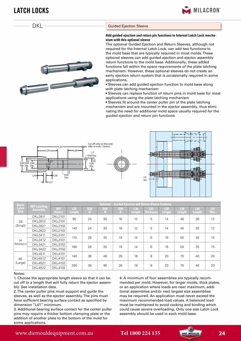
Guided Ejection Sleeve
Add guided ejection and return pin functions to Internal Latch Lock mecha-nism with this optional sleeveThe optional Guided Ejection and Return Sleeves, although not required for the Internal Latch Lock, can add two functions to the mold base that are typically required in most molds. These optional sleeves can add guided ejection and ejector assembly return functions to the mold base. Additionally, these added functions fall within the space requirements of the plate latching mechanism. However, these optional sleeves do not create an early ejection return system that is occasionally required in some applications.• Sleeves can add guided ejection function to mold base alongwith plate latching mechanism• Sleeves can replace function of return pins in mold base for mostapplications using the plate latching mechanism• Sleeves fit around the center puller pin of the plate latchingmechanism and are mounted in the ejector assembly, thus elimi-nating the need for additional mold space usually required for theguided ejection and return pin functions
Notes:1. Choose the appropriate length sleeve so that it can becut off to a length that will fully return the ejector assem-bly. See installation data.2. The center puller pins must support and guide thesleeves, as well as the ejector assembly. The pins musthave sufficient bearing surface contact as specified bydimension “L41” minimum.3. Additional bearing surface contact for the center pullerpins may require a thicker bottom clamping plate or theaddition of another plate to the bottom of the mold forsome applications.
4. A minimum of four assemblies are typically recom-mended per mold. However, for larger molds, thick plates,or an application where loads are near maximum, addi-tional assemblies and/or next largest size assembliesmay be required. An application must never exceed themaximum recommended load values. A balanced loadmust be maintained to avoid cocking and binding whichcould cause severe overloading. Only one size Latch Lockassembly should be used in each mold base.
BasicLatchSize
REF Latching Assembly
Optional – Guided Ejection and Return Sleeve FeaturesREF
SleeveL35
LengthD28
ØD29Ø
D30Ø
L36Length
L37Thickness
L38Length
L39Length
L40Length
L41Min.
28 (Small)
DKL-2811 DKL-210190 24 30 16 12 5 14 40 30 12
DKL-2812 DKL-2101DKL-2821 DKL-2102
140 24 30 16 12 5 14 40 30 12DKL-2822 DKL-2102
34(Medium)
DKL-3411 DKL-3101110 28 35 19 14 6 16 50 35 15
DKL-3412 DKL-3101DKL-3421 DKL-3102
160 28 35 19 14 6 16 50 35 15DKL-3422 DKL-3102
45.(Large)
DKL-4511 DKL-4101140 38 46 26 18 8 20 70 40 20
DKL-4512 DKL-4101DKL-4521 DKL-4102
200 38 46 26 18 8 20 70 40 20DKL-4522 DKL-4102
L35L40L39
D28Dia.
D28Dia.
L37
L38L36
D29Dia.
D30Dia.
D30 Dia.
D28Dia.
D30Dia.
+0.02+0
+0.9+0.6
+0.02+0
-0.01-0.03
+1.6+1
L41Min.
Cut o� only on this end;refer to note 1 below.
www.diemouldequipment.com.au Tel 1800 224 135 24
FW1800
two-stage ejeCtors
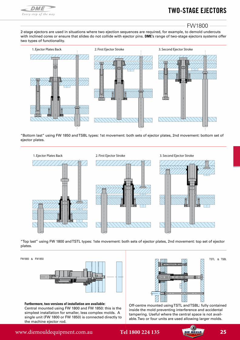
Furthermore, two versions of installation are available:Central mounted using FW 1800 and FW 1850: this is the simplest installation for smaller, less complex molds. A single unit (FW 1800 or FW 1850) is connected directly to the machine ejector rod.
Off-centre mounted using TSTL and TSBL: fully contained inside the mold preventing interference and accidental tampering. Useful where the central space is not avail-able. Two or four units are used allowing larger molds.
& &
“Top last” using FW 1800 and TSTL types: 1ste movement: both sets of ejector plates, 2nd movement: top set of ejector plates.
1. Ejector Plates Back 2. First Ejector Stroke 3. Second Ejector Stroke
2-stage ejectors are used in situations where two ejection sequences are required, for example, to demold undercutswith inclined cores or ensure that slides do not collide with ejector pins. DME’s range of two-stage ejectors systems offertwo types of functionality.
1. Ejector Plates Back 2. First Ejector Stroke 3. Second Ejector Stroke
“Bottom last” using FW 1850 and TSBL types: 1st movement: both sets of ejector plates, 2nd movement: bottom set of ejector plates.
www.diemouldequipment.com.au Tel 1800 224 135 25
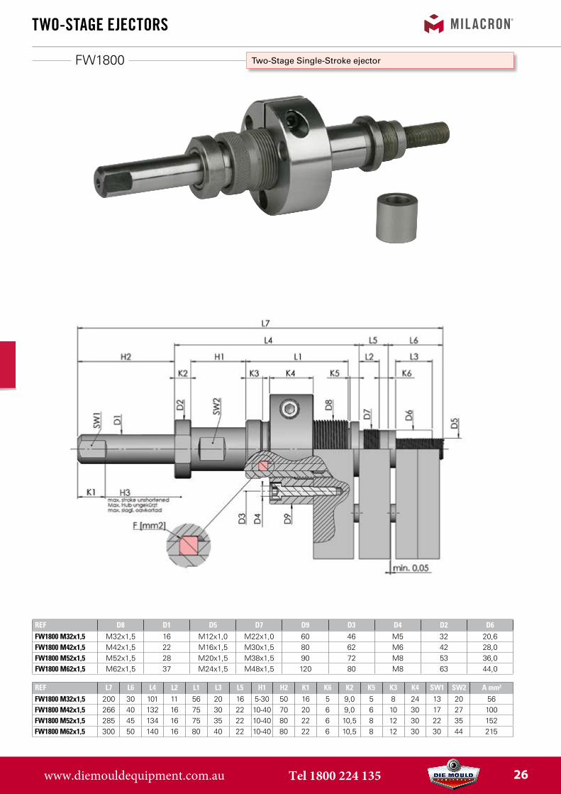
FW1800
REF D8 D1 D5 D7 D9 D3 D4 D2 D6FW1800 M32x1,5 M32x1,5 16 M12x1,0 M22x1,0 60 46 M5 32 20,6FW1800 M42x1,5 M42x1,5 22 M16x1,5 M30x1,5 80 62 M6 42 28,0FW1800 M52x1,5 M52x1,5 28 M20x1,5 M38x1,5 90 72 M8 53 36,0FW1800 M62x1,5 M62x1,5 37 M24x1,5 M48x1,5 120 80 M8 63 44,0
REF L7 L6 L4 L2 L1 L3 L5 H1 H2 K1 K6 K2 K5 K3 K4 SW1 SW2 A mm²FW1800 M32x1,5 200 30 101 11 56 20 16 5-30 50 16 5 9,0 5 8 24 13 20 56FW1800 M42x1,5 266 40 132 16 75 30 22 10-40 70 20 6 9,0 6 10 30 17 27 100FW1800 M52x1,5 285 45 134 16 75 35 22 10-40 80 22 6 10,5 8 12 30 22 35 152FW1800 M62x1,5 300 50 140 16 80 40 22 10-40 80 22 6 10,5 8 12 30 30 44 215
two-stage ejeCtors
Two-Stage Single-Stroke ejector
Part designationNr. 1 Ejector pin
2 Sliding sleeve3 Adjusting bush
4 Assembly flange5 Segment6 Stop ring7 Spacer ring
*Recommended thread
www.diemouldequipment.com.au Tel 1800 224 135 26
two-stage ejeCtors
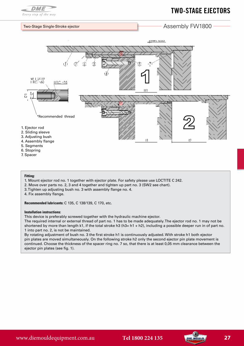
Two-Stage Single-Stroke ejector
Part designationNr. 1 Ejector pin
2 Sliding sleeve3 Adjusting bush
4 Assembly flange5 Segment6 Stop ring7 Spacer ring
*Recommended thread
Fitting:1. Mount ejector rod no. 1 together with ejector plate. For safety please use LOCTITE C 242.2. Move over parts no. 2, 3 and 4 together and tighten up part no. 3 (SW2 see chart).3. Tighten up adjusting bush no. 3 with assembly flange no. 4.4. Fix assembly flange.
Recommended lubricants: C 135, C 138/139, C 170, etc.
Installation instructions:This device is preferably screwed together with the hydraulic machine ejector. The required internal or external thread of part no. 1 has to be made adequately. The ejector rod no. 1 may not be shortened by more than length k1, if the total stroke h3 (h3= h1 + h2), including a possible deeper run in of part no. 1 into part no. 2, is not be maintained. By rotating adjustment of bush no. 3 the first stroke h1 is continuously adjusted. With stroke h1 both ejector pin plates are moved simultaneously. On the following stroke h2 only the second ejector pin plate movement is continued. Choose the thickness of the spacer ring no. 7 so, that there is at least 0,05 mm clearance between the ejector pin plates (see fig. 1).
1. Ejector rod2. Sliding sleeve3. Adjusting bush4. Assembly flange5. Segments6. Stopring7. Spacer
Assembly FW1800
www.diemouldequipment.com.au Tel 1800 224 135 27
FW1850
two-stage ejeCtors
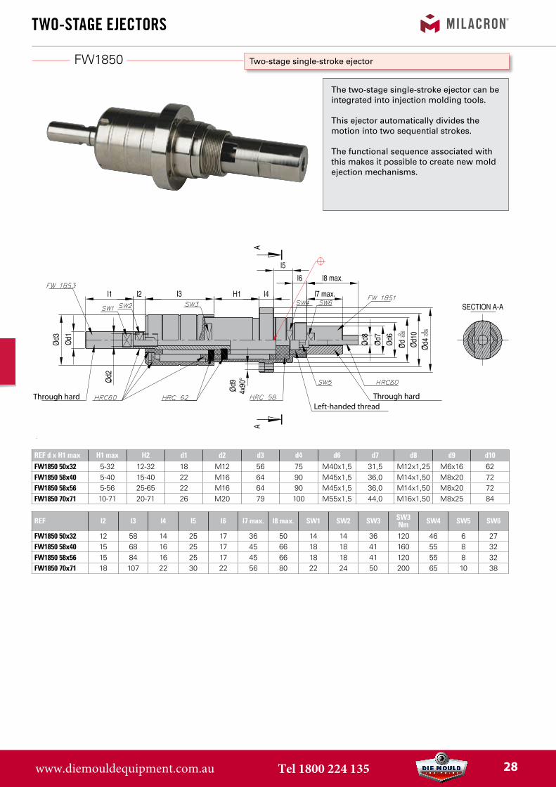
Two-stage single-stroke ejector
The two-stage single-stroke ejector can be integrated into injection molding tools.
This ejector automatically divides the motion into two sequential strokes.
The functional sequence associated with this makes it possible to create new mold ejection mechanisms.
Through hardLeft-handed thread
Through hard
REF d x H1 max H1 max H2 d1 d2 d3 d4 d6 d7 d8 d9 d10FW1850 50x32 5-32 12-32 18 M12 56 75 M40x1,5 31,5 M12x1,25 M6x16 62FW1850 58x40 5-40 15-40 22 M16 64 90 M45x1,5 36,0 M14x1,50 M8x20 72FW1850 58x56 5-56 25-65 22 M16 64 90 M45x1,5 36,0 M14x1,50 M8x20 72FW1850 70x71 10-71 20-71 26 M20 79 100 M55x1,5 44,0 M16x1,50 M8x25 84
REF l2 l3 l4 l5 l6 l7 max. l8 max. SW1 SW2 SW3 SW3Nm SW4 SW5 SW6
FW1850 50x32 12 58 14 25 17 36 50 14 14 36 120 46 6 27FW1850 58x40 15 68 16 25 17 45 66 18 18 41 160 55 8 32FW1850 58x56 15 84 16 25 17 45 66 18 18 41 120 55 8 32FW1850 70x71 18 107 22 30 22 56 80 22 24 50 200 65 10 38
www.diemouldequipment.com.au Tel 1800 224 135 28
two-stage ejeCtors
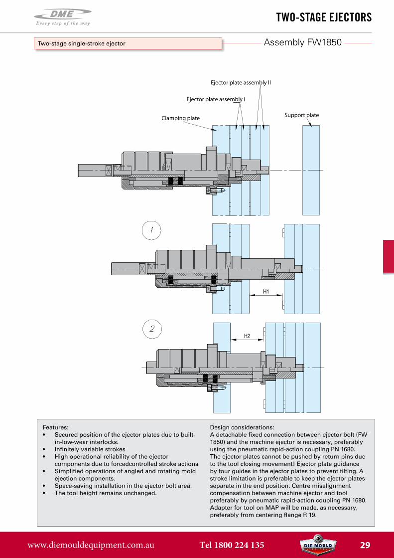
Ejector plate assembly II
Ejector plate assembly I
Support plateClamping plate
Assembly FW1850Two-stage single-stroke ejector
Features:• Secured position of the ejector plates due to built-
in-low-wear interlocks.• Infinitely variable strokes• High operational reliability of the ejector
components due to forcedcontrolled stroke actions• Simplified operations of angled and rotating mold
ejection components.• Space-saving installation in the ejector bolt area.• The tool height remains unchanged.
Design considerations:A detachable fixed connection between ejector bolt (FW 1850) and the machine ejector is necessary, preferably using the pneumatic rapid-action coupling PN 1680. The ejector plates cannot be pushed by return pins due to the tool closing movement! Ejector plate guidance by four guides in the ejector plates to prevent tilting. A stroke limitation is preferable to keep the ejector plates separate in the end position. Centre misalignment compensation between machine ejector and tool preferably by pneumatic rapid-action coupling PN 1680. Adapter for tool on MAP will be made, as necessary, preferably from centering flange R 19.
www.diemouldequipment.com.au Tel 1800 224 135 29
TSTL
two-stage ejeCtors
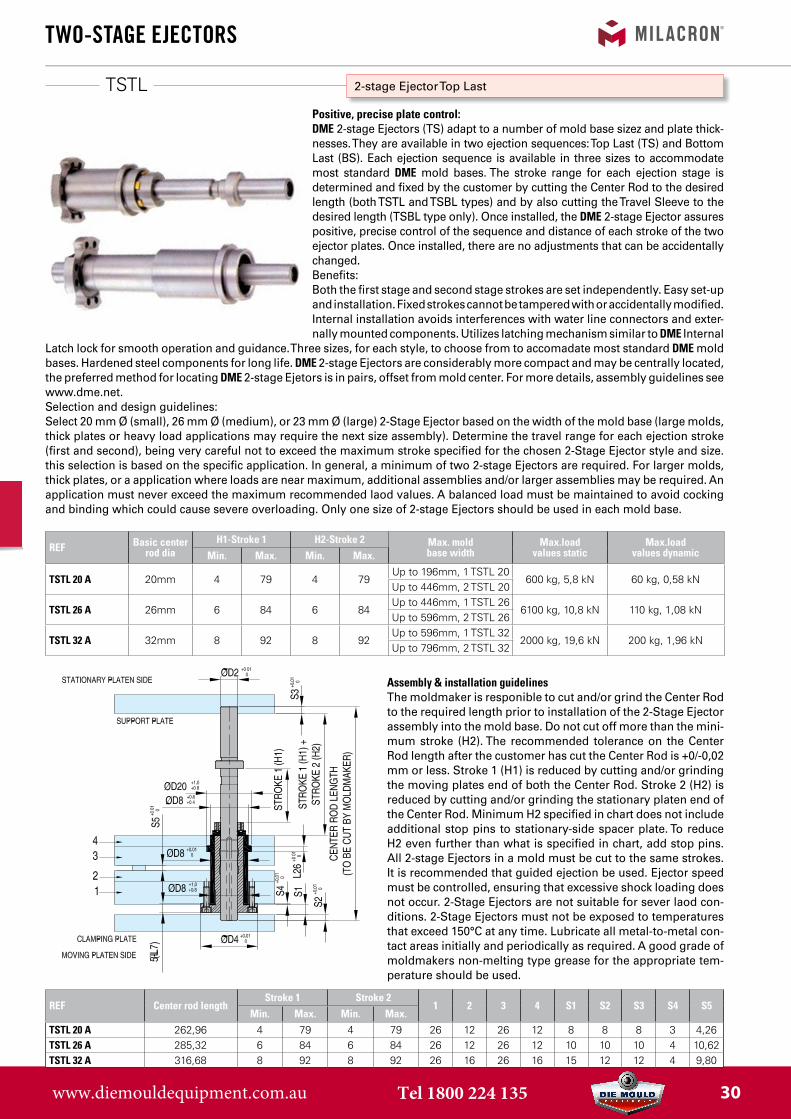
2-stage Ejector Top Last
Positive, precise plate control:DME 2-stage Ejectors (TS) adapt to a number of mold base sizez and plate thick-nesses. They are available in two ejection sequences: Top Last (TS) and Bottom Last (BS). Each ejection sequence is available in three sizes to accommodate most standard DME mold bases. The stroke range for each ejection stage is determined and fixed by the customer by cutting the Center Rod to the desired length (both TSTL and TSBL types) and by also cutting the Travel Sleeve to the desired length (TSBL type only). Once installed, the DME 2-stage Ejector assures positive, precise control of the sequence and distance of each stroke of the two ejector plates. Once installed, there are no adjustments that can be accidentally changed.Benefits:Both the first stage and second stage strokes are set independently. Easy set-up and installation. Fixed strokes cannot be tampered with or accidentally modified. Internal installation avoids interferences with water line connectors and exter-nally mounted components. Utilizes latching mechanism similar to DME Internal
Latch lock for smooth operation and guidance. Three sizes, for each style, to choose from to accomadate most standard DME mold bases. Hardened steel components for long life. DME 2-stage Ejectors are considerably more compact and may be centrally located, the preferred method for locating DME 2-stage Ejetors is in pairs, offset from mold center. For more details, assembly guidelines see www.dme.net.Selection and design guidelines:Select 20 mm Ø (small), 26 mm Ø (medium), or 23 mm Ø (large) 2-Stage Ejector based on the width of the mold base (large molds, thick plates or heavy load applications may require the next size assembly). Determine the travel range for each ejection stroke (first and second), being very careful not to exceed the maximum stroke specified for the chosen 2-Stage Ejector style and size. this selection is based on the specific application. In general, a minimum of two 2-stage Ejectors are required. For larger molds, thick plates, or a application where loads are near maximum, additional assemblies and/or larger assemblies may be required. An application must never exceed the maximum recommended laod values. A balanced load must be maintained to avoid cocking and binding which could cause severe overloading. Only one size of 2-stage Ejectors should be used in each mold base.
REF Basic center rod dia
H1-Stroke 1 H2-Stroke 2 Max. mold base width
Max.load values static
Max.load values dynamicMin. Max. Min. Max.
TSTL 20 A 20mm 4 79 4 79Up to 196mm, 1 TSTL 20
600 kg, 5,8 kN 60 kg, 0,58 kNUp to 446mm, 2 TSTL 20
TSTL 26 A 26mm 6 84 6 84Up to 446mm, 1 TSTL 26
6100 kg, 10,8 kN 110 kg, 1,08 kNUp to 596mm, 2 TSTL 26
TSTL 32 A 32mm 8 92 8 92Up to 596mm, 1 TSTL 32
2000 kg, 19,6 kN 200 kg, 1,96 kNUp to 796mm, 2 TSTL 32
Assembly & installation guidelinesThe moldmaker is responible to cut and/or grind the Center Rod to the required length prior to installation of the 2-Stage Ejector assembly into the mold base. Do not cut off more than the mini-mum stroke (H2). The recommended tolerance on the Center Rod length after the customer has cut the Center Rod is +0/-0,02 mm or less. Stroke 1 (H1) is reduced by cutting and/or grinding the moving plates end of both the Center Rod. Stroke 2 (H2) is reduced by cutting and/or grinding the stationary platen end of the Center Rod. Minimum H2 specified in chart does not include additional stop pins to stationary-side spacer plate. To reduce H2 even further than what is specified in chart, add stop pins. All 2-stage Ejectors in a mold must be cut to the same strokes. It is recommended that guided ejection be used. Ejector speed must be controlled, ensuring that excessive shock loading does not occur. 2-Stage Ejectors are not suitable for sever laod con-ditions. 2-Stage Ejectors must not be exposed to temperatures that exceed 150°C at any time. Lubricate all metal-to-metal con-tact areas initially and periodically as required. A good grade of moldmakers non-melting type grease for the appropriate tem-perature should be used.
REF Center rod lengthStroke 1 Stroke 2
1 2 3 4 S1 S2 S3 S4 S5Min. Max. Min. Max.
TSTL 20 A 262,96 4 79 4 79 26 12 26 12 8 8 8 3 4,26TSTL 26 A 285,32 6 84 6 84 26 12 26 12 10 10 10 4 10,62TSTL 32 A 316,68 8 92 8 92 26 16 26 16 15 12 12 4 9,80
www.diemouldequipment.com.au Tel 1800 224 135 30
TSTL
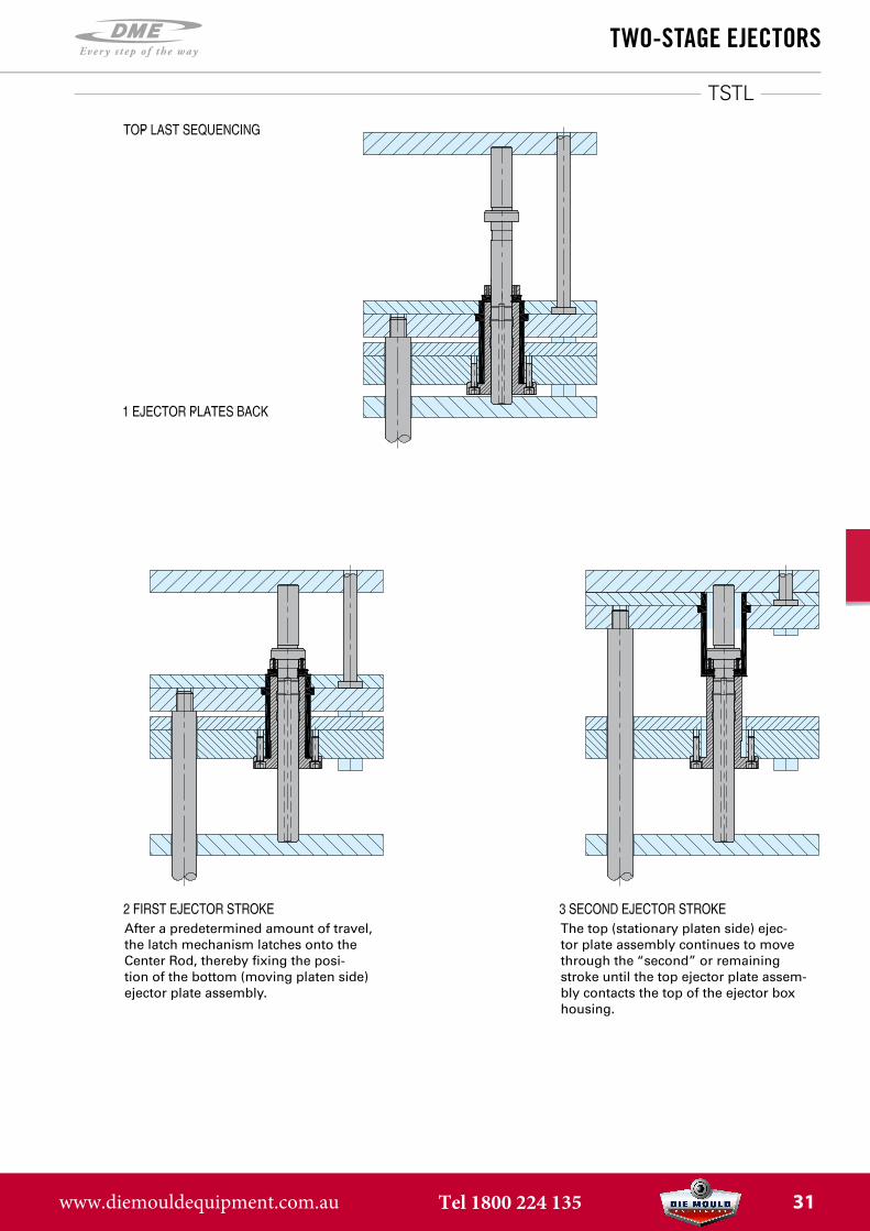
two-stage ejeCtors
The top (stationary platen side) ejec-tor plate assembly continues to move through the “second” or remaining stroke until the top ejector plate assem-bly contacts the top of the ejector box housing.
After a predetermined amount of travel, the latch mechanism latches onto the Center Rod, thereby fixing the posi-tion of the bottom (moving platen side) ejector plate assembly.
www.diemouldequipment.com.au Tel 1800 224 135 31
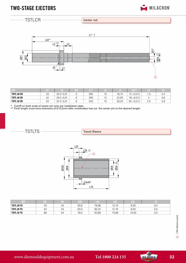
TSTLTS
TSTLCR
REF D8 D9 D20 L10 L25 L26 C4TSTL 20 TS 43 34 50,8 79,96 12,70 6,00 0,5TSTL 26 TS 54 43 63,0 85,32 12,70 8,00 0,5TSTL 32 TS 68 54 78,0 93,68 15,88 10,00 0,5
two-stage ejeCtors
CAD
refe
renc
e po
int
Travel Sleeve
Center rod
REF D1 D2 D17 L1* L2 L3 L22** C1 R1TSTL 20 CR 33 20 0 -0,01 5 265 10 18,74 72 +0,5 0 1,5 0,4TSTL 26 CR 42 26 0 -0,01 6 290 12 22,93 76 +0,5 0 2 0,8TSTL 32 CR 53 32 0 -0,01 6 320 15 28,25 82 +0,5 0 2,5 0,8
* Cutoff on both ends of center pin only per installation data.** Final length must have tolerance of 0/-0,2mm after moldmaker has cut the center pin to the desired length.
www.diemouldequipment.com.au Tel 1800 224 135 32
TSTLKT
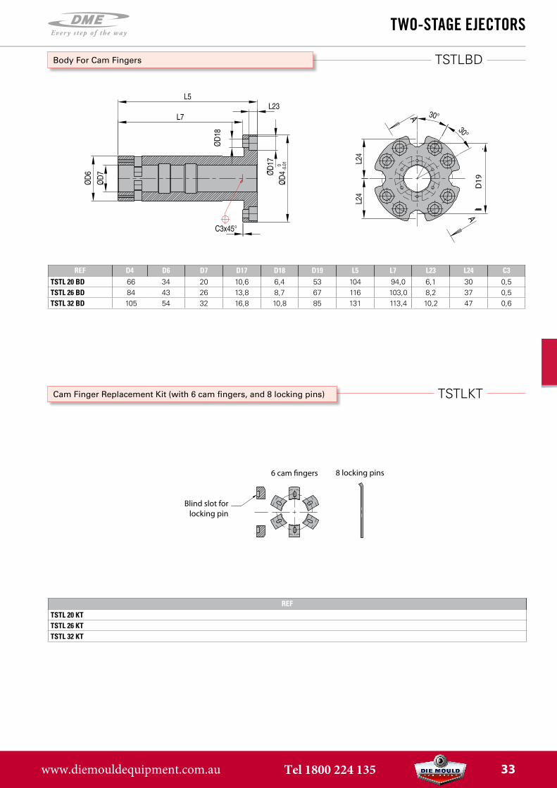
TSTLBD
D19
REF D4 D6 D7 D17 D18 D19 L5 L7 L23 L24 C3TSTL 20 BD 66 34 20 10,6 6,4 53 104 94,0 6,1 30 0,5TSTL 26 BD 84 43 26 13,8 8,7 67 116 103,0 8,2 37 0,5TSTL 32 BD 105 54 32 16,8 10,8 85 131 113,4 10,2 47 0,6
REFTSTL 20 KTTSTL 26 KTTSTL 32 KT
two-stage ejeCtors
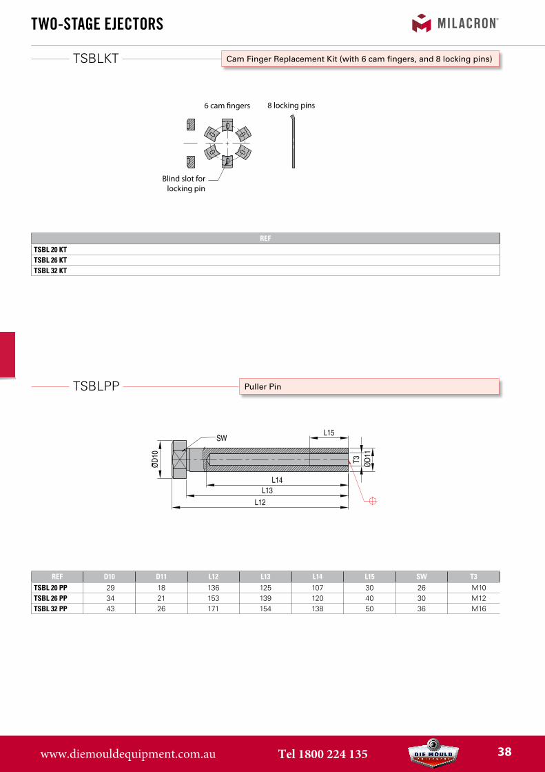
Cam Finger Replacement Kit (with 6 cam fingers, and 8 locking pins)
6 cam �ngers 8 locking pins
Blind slot forlocking pin
Body For Cam Fingers
www.diemouldequipment.com.au Tel 1800 224 135 33
TSBL
two-stage ejeCtors
CAD
refe
renc
e po
int
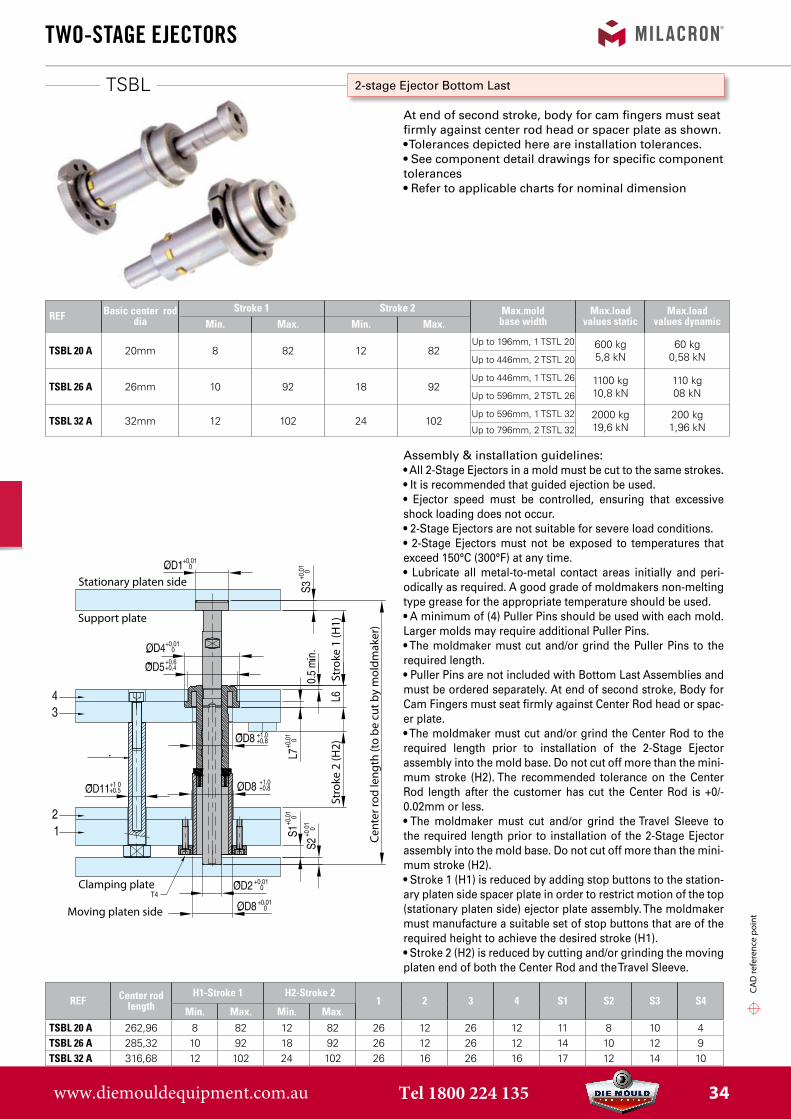
Assembly & installation guidelines:• All 2-Stage Ejectors in a mold must be cut to the same strokes.• It is recommended that guided ejection be used.• Ejector speed must be controlled, ensuring that excessiveshock loading does not occur.• 2-Stage Ejectors are not suitable for severe load conditions.• 2-Stage Ejectors must not be exposed to temperatures thatexceed 150°C (300°F) at any time.• Lubricate all metal-to-metal contact areas initially and peri-odically as required. A good grade of moldmakers non-melting type grease for the appropriate temperature should be used.• A minimum of (4) Puller Pins should be used with each mold.Larger molds may require additional Puller Pins.• The moldmaker must cut and/or grind the Puller Pins to therequired length.• Puller Pins are not included with Bottom Last Assemblies andmust be ordered separately. At end of second stroke, Body forCam Fingers must seat firmly against Center Rod head or spac-er plate.• The moldmaker must cut and/or grind the Center Rod to therequired length prior to installation of the 2-Stage Ejectorassembly into the mold base. Do not cut off more than the mini-mum stroke (H2). The recommended tolerance on the CenterRod length after the customer has cut the Center Rod is +0/-0.02mm or less.• The moldmaker must cut and/or grind the Travel Sleeve tothe required length prior to installation of the 2-Stage Ejectorassembly into the mold base. Do not cut off more than the mini-mum stroke (H2).• Stroke 1 (H1) is reduced by adding stop buttons to the station-ary platen side spacer plate in order to restrict motion of the top (stationary platen side) ejector plate assembly. The moldmakermust manufacture a suitable set of stop buttons that are of therequired height to achieve the desired stroke (H1).• Stroke 2 (H2) is reduced by cutting and/or grinding the movingplaten end of both the Center Rod and the Travel Sleeve.
Stationary platen side
Support plate
Clamping plate
Moving platen side
Stro
ke 1
(H1)
Stro
ke 2
(H2)
Cent
er ro
d le
ngth
(to
be c
ut b
y m
oldm
aker
)
2-stage Ejector Bottom Last
At end of second stroke, body for cam fingers must seat firmly against center rod head or spacer plate as shown.• Tolerances depicted here are installation tolerances.• See component detail drawings for specific componenttolerances• Refer to applicable charts for nominal dimension
REF Center rod length
H1-Stroke 1 H2-Stroke 21 2 3 4 S1 S2 S3 S4
Min. Max. Min. Max.TSBL 20 A 262,96 8 82 12 82 26 12 26 12 11 8 10 4TSBL 26 A 285,32 10 92 18 92 26 12 26 12 14 10 12 9TSBL 32 A 316,68 12 102 24 102 26 16 26 16 17 12 14 10
REF Basic center rod dia
Stroke 1 Stroke 2 Max.mold base width
Max.load values static
Max.load values dynamicMin. Max. Min. Max.
TSBL 20 A 20mm 8 82 12 82Up to 196mm, 1 TSTL 20 600 kg
5,8 kN60 kg
0,58 kNUp to 446mm, 2 TSTL 20
TSBL 26 A 26mm 10 92 18 92Up to 446mm, 1 TSTL 26 1100 kg
10,8 kN110 kg08 kNUp to 596mm, 2 TSTL 26
TSBL 32 A 32mm 12 102 24 102Up to 596mm, 1 TSTL 32 2000 kg
19,6 kN200 kg1,96 kNUp to 796mm, 2 TSTL 32
www.diemouldequipment.com.au Tel 1800 224 135 34
TSBL
two-stage ejeCtors
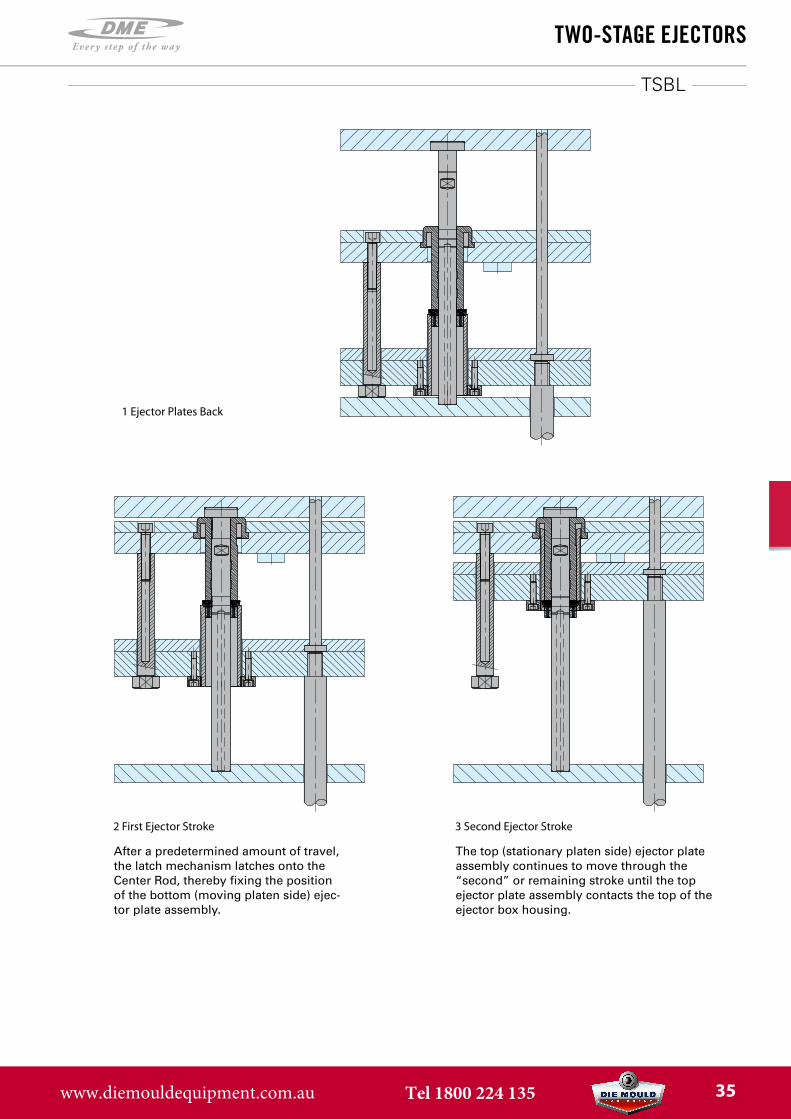
1 Ejector Plates Back
2 First Ejector Stroke 3 Second Ejector Stroke
After a predetermined amount of travel, the latch mechanism latches onto the Center Rod, thereby fixing the position of the bottom (moving platen side) ejec-tor plate assembly.
The top (stationary platen side) ejector plate assembly continues to move through the “second” or remaining stroke until the top ejector plate assembly contacts the top of the ejector box housing.
www.diemouldequipment.com.au Tel 1800 224 135 35
TSBLTS
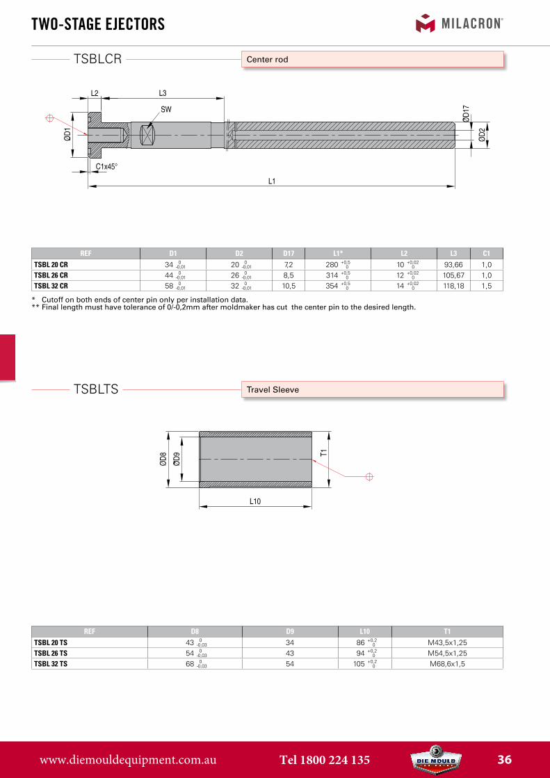
TSBLCR
REF D8 D9 L10 T1TSBL 20 TS 43 0
-0,03 34 86 +0,2 0 M43,5x1,25
TSBL 26 TS 54 0 -0,03 43 94 +0,2
0 M54,5x1,25TSBL 32 TS 68 0
-0,03 54 105 +0,2 0 M68,6x1,5
two-stage ejeCtors
Travel Sleeve
Center rod
REF D1 D2 D17 L1* L2 L3 C1TSBL 20 CR 34 0
-0,01 20 0-0,01 7,2 280 +0,5
0 10 +0,02 0 93,66 1,0
TSBL 26 CR 44 0 -0,01 26 0
-0,01 8,5 314 +0,5 0 12 +0,02
0 105,67 1,0TSBL 32 CR 58 0
-0,01 32 0 -0,01 10,5 354 +0,5
0 14 +0,02 0 118,18 1,5
* Cutoff on both ends of center pin only per installation data.** Final length must have tolerance of 0/-0,2mm after moldmaker has cut the center pin to the desired length.
www.diemouldequipment.com.au Tel 1800 224 135 36
TSBLBD
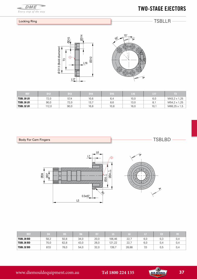
TSBLLR
REF D12 D13 D14 D15 L16 L17 T3
TSBL 20 LR 72,0 57,4 10,6 6,4 10,0 6,0 M43,2 x 1,25TSBL 26 LR 90,0 72,0 13,7 8,6 13,0 8,1 M54,2 x 1,25TSBL 32 LR 112,0 90,0 16,8 10,8 16,0 10,1 M68,25 x 1,5
REF D4 D5 D6 D7 L5 L6 L7 C2 R1
TSBL 20 BD 58,2 50,8 34,0 20,0 106,46 22,7 6,0 0,3 0,4TSBL 26 BD 70,0 62,8 43,0 26,0 121,22 22,7 6,0 0,4 0,4
TSBL 32 BD 87,0 78,0 54,0 32,0 139,7 28,88 7,0 0,5 0,4
two-stage ejeCtors
Body For Cam Fingers
Locking Ring
Ø D
13 (B
old
diam
eter
)
www.diemouldequipment.com.au Tel 1800 224 135 37
TSBLPP
TSBLKT
REF D10 D11 L12 L13 L14 L15 SW T3TSBL 20 PP 29 18 136 125 107 30 26 M10TSBL 26 PP 34 21 153 139 120 40 30 M12TSBL 32 PP 43 26 171 154 138 50 36 M16
REFTSBL 20 KTTSBL 26 KTTSBL 32 KT
two-stage ejeCtors
Puller Pin
Cam Finger Replacement Kit (with 6 cam fingers, and 8 locking pins)
6 cam �ngers 8 locking pins
Blind slot forlocking pin
www.diemouldequipment.com.au Tel 1800 224 135 38

Coarse PitCh axLes
www.diemouldequipment.com.au Tel 1800 224 135 39
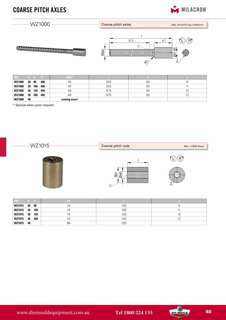
WZ1015
WZ1000
REF d h d1 l zWZ1015 28 80 74 100 9WZ1015 28 160 74 100 11WZ1015 38 120 74 120 10WZ1015 38 200 74 120 12WZ1015 48 96 120
Coarse PitCh axLes
Coarse pitch nuts Mat.: 2.0550 Brass
Coarse pitch axles Mat.: W1.0715 max 570N/mm²
REF d h l1 d1h8* l k zWZ1000 28 80 400 40 525 93 9WZ1000 28 160 400 40 525 93 11WZ1000 38 120 450 48 575 93 10WZ1000 38 200 450 48 575 93 12WZ1000 48 coming soon!
* Special sizes upon request
www.diemouldequipment.com.au Tel 1800 224 135 40
WZ1030
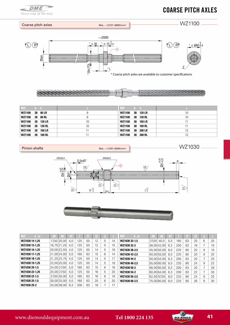
WZ1100
REF d h zWZ1100 28 80 LR 9WZ1100 28 80 RL 9WZ1100 28 120 LR 10WZ1100 28 120 RL 10WZ1100 28 160 LR 11WZ1100 28 160 RL 11
REF d h zWZ1100 38 120 LR 10WZ1100 38 120 RL 10WZ1100 38 160 LR 11WZ1100 38 160 RL 11WZ1100 38 200 LR 12WZ1100 38 200 RL 12
REF d m d0 dk d1 l l1 l2 a zWZ1030 14-1,25 17,50 20,00 4,0 125 50 12 5 14WZ1030 15-1,25 18,75 21,25 4,0 125 50 12 5 15WZ1030 16-1,25 20,00 22,50 4,0 125 50 14 5 16WZ1030 17-1,25 21,00 24,00 5,0 160 63 15 6 14WZ1030 18-1,25 21,25 23,75 4,0 125 50 14 5 17WZ1030 19-1,25 22,50 25,00 4,0 125 50 14 5 18WZ1030 20-1,5 24,00 27,00 5,0 160 63 15 6 16WZ1030 22-1,25 25,00 27,50 5,0 125 50 16 5 20WZ1030 22-1,5 27,00 30,00 5,0 160 63 16 6 18WZ1030 25-1,5 30,00 33,00 5,0 160 63 20 6 20WZ1030 29-2 34,00 38,00 6,3 200 63 18 7 17
REF d m d0 dk d1 l l1 l2 a zWZ1030 32-1,5 37,50 40,5 5,0 160 63 20 6 25WZ1030 32-2 38,00 42,00 6,3 200 63 18 7 19WZ1030 38-2,5 45,00 50,00 8,0 225 80 20 9 18WZ1030 43-2,5 50,00 55,00 8,0 225 80 20 9 20WZ1030 44-2 50,00 54,00 6,3 200 63 20 7 25WZ1030 48-2,5 55,00 60,00 8,0 225 80 24 9 22WZ1030 50-2 56,00 60,00 6,3 200 63 20 7 28WZ1030 54-2 60,00 64,00 6,3 200 63 22 7 30WZ1030 56-2,5 62,50 67,50 8,0 225 80 24 9 25WZ1030 68-2,5 75,00 80,00 8,0 225 80 26 9 30
Coarse PitCh axLes
Pinion shafts Mat.: ~1.2767~830N/mm²
Coarse pitch axles Mat.: ~1.0727~980N/mm²
<2000
* Coarse pitch axles are available to customer speci�cations
www.diemouldequipment.com.au Tel 1800 224 135 41
WZ1050
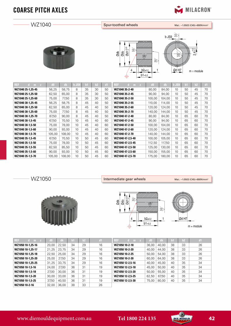
WZ1040
REF d m z d0 dk b JS9 b1 b2 d1WZ1040 25-1,25-45 56,25 58,75 8 35 30 50WZ1040 25-1,25-50 62,50 65,00 8 35 30 50WZ1040 25-1,25-60 75,00 77,50 8 35 30 50WZ1040 30-1,25-45 56,25 58,75 8 45 40 50WZ1040 30-1,25-50 62,50 65,00 8 45 40 50WZ1040 30-1,25-60 75,00 77,50 8 45 40 50WZ1040 30-1,25-70 87,50 90,00 8 45 40 50WZ1040 30-1,5-45 67,50 70,50 10 45 40 60WZ1040 30-1,5-50 75,00 78,00 10 45 40 60WZ1040 30-1,5-60 90,00 93,00 10 45 40 60WZ1040 30-1,5-70 105,00 108,00 10 45 40 60WZ1040 35-1,5-45 67,50 70,50 10 50 45 60WZ1040 35-1,5-50 75,00 78,00 10 50 45 60WZ1040 35-1,5-55 82,50 85,50 10 50 45 60WZ1040 35-1,5-60 90,00 93,00 10 50 45 60WZ1040 35-1,5-70 105,00 108,00 10 50 45 60
REF d m z d0 dk b JS9 b1 b2 d1WZ1040 35-2-40 80,00 84,00 10 50 45 70WZ1040 35-2-45 90,00 94,00 10 50 45 70WZ1040 35-2-50 100,00 104,00 10 50 45 70WZ1040 35-2-55 110,00 114,00 10 50 45 70WZ1040 35-2-60 120,00 124,00 10 50 45 70WZ1040 35-2-70 140,00 144,00 10 50 45 70WZ1040 47-2-40 80,00 84,00 10 65 60 70WZ1040 47-2-45 90,00 94,00 10 65 60 70WZ1040 47-2-50 100,00 104,00 10 65 60 70WZ1040 47-2-60 120,00 124,00 10 65 60 70WZ1040 47-2-70 140,00 144,00 10 65 60 70WZ1040 47-2,5-40 100,00 105,00 10 65 60 70WZ1040 47-2,5-45 112,50 117,50 10 65 60 70WZ1040 47-2,5-50 125,00 130,00 10 65 60 70WZ1040 47-2,5-60 150,00 155,00 10 65 60 70WZ1040 47-2,5-70 175,00 180,00 10 65 60 70
REF d m z d0 dk b1 b2 d1WZ1050 10-1,25-16 20,00 22,50 34 29 16WZ1050 10-1,25-17 21,25 23,75 34 29 16WZ1050 10-1,25-18 22,50 25,00 34 29 16WZ1050 10-1,25-20 25,00 27,50 34 29 16WZ1050 10-1,25-25 31,25 33,75 34 29 16WZ1050 10-1,5-16 24,00 27,00 36 31 19WZ1050 10-1,5-18 27,00 30,00 36 31 19WZ1050 10-1,5-20 30,00 33,00 36 31 19WZ1050 10-1,5-25 37,50 40,50 36 31 19WZ1050 10-2-16 32,00 36,00 38 33 26
REF d m z d0 dk b1 b2 d1WZ1050 10-2-18 36,00 40,00 38 33 26WZ1050 10-2-20 40,00 44,00 38 33 26WZ1050 10-2-25 50,00 54,00 38 33 26WZ1050 10-2-30 60,00 64,00 38 33 26WZ1050 12-2,5-16 40,00 45,00 40 35 34WZ1050 12-2,5-18 45,00 50,00 40 35 34WZ1050 12-2,5-20 50,00 55,00 40 35 34WZ1050 12-2,5-25 62,50 67,50 40 35 34WZ1050 12-2,5-30 75,00 80,00 40 35 34
Coarse PitCh axLes
Intermediate gear wheels Mat.: ~1.0503 (C45)~690N/mm²
Spur-toothed wheels Mat.: ~1.0503 (C45)~690N/mm²
www.diemouldequipment.com.au Tel 1800 224 135 42
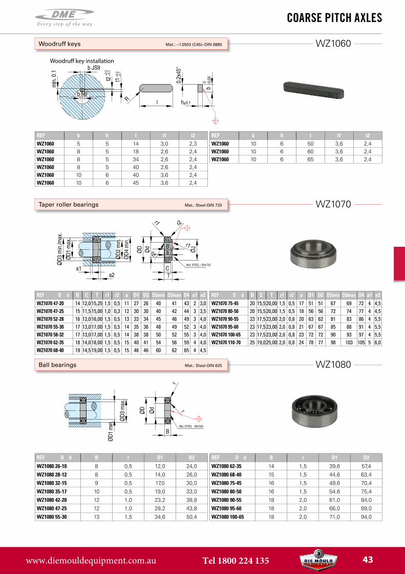
WZ1080
WZ1070
WZ1060
REF b h l t1 t2WZ1060 5 5 14 3,0 2,3WZ1060 8 5 18 2,6 2,4WZ1060 8 5 34 2,6 2,4WZ1060 8 5 40 2,6 2,4WZ1060 10 6 40 3,6 2,4WZ1060 10 6 45 3,6 2,4
REF b h l t1 t2WZ1060 10 6 50 3,6 2,4WZ1060 10 6 60 3,6 2,4WZ1060 10 6 65 3,6 2,4
REF D d B C T r1 r2 a D1 D2 D3min D3max D4 a1 a2WZ1070 47-20 14 12,0 15,25 1,5 0,5 11 27 26 40 41 43 2 3,0WZ1070 47-25 15 11,5 15,00 1,0 0,3 12 30 30 40 42 44 3 3,5WZ1070 52-28 16 12,0 16,00 1,5 0,5 13 33 34 45 46 49 3 4,0WZ1070 55-30 17 13,0 17,00 1,5 0,5 14 35 36 48 49 52 3 4,0WZ1070 58-32 17 13,0 17,00 1,5 0,5 14 38 38 50 52 55 3 4,0WZ1070 62-35 18 14,0 18,00 1,5 0,5 15 40 41 54 56 59 4 4,0WZ1070 68-40 19 14,5 19,00 1,5 0,5 15 46 46 60 62 65 4 4,5
REF D d B C T r1 r2 a D1 D2 D3min D3max D4 a1 a2WZ1070 75-45 20 15,5 20,00 1,5 0,5 17 51 51 67 69 72 4 4,5WZ1070 80-50 20 15,5 20,00 1,5 0,5 18 56 56 72 74 77 4 4,5WZ1070 90-55 23 17,5 23,00 2,0 0,8 20 63 62 81 83 86 4 5,5WZ1070 95-60 23 17,5 23,00 2,0 0,8 21 67 67 85 88 91 4 5,5WZ1070 100-65 23 17,5 23,00 2,0 0,8 23 72 72 90 93 97 4 5,5WZ1070 110-70 25 19,0 25,00 2,0 0,8 24 78 77 98 103 105 5 6,0
REF D d B r D1 D2
WZ1080 26-10 8 0,5 12,0 24,0
WZ1080 28-12 8 0,5 14,0 26,0
WZ1080 32-15 9 0,5 17,0 30,0
WZ1080 35-17 10 0,5 19,0 33,0
WZ1080 42-20 12 1,0 23,2 38,8
WZ1080 47-25 12 1,0 28,2 43,8
WZ1080 55-30 13 1,5 34,6 50,4
REF D d B r D1 D2
WZ1080 62-35 14 1,5 39,6 57,4
WZ1080 68-40 15 1,5 44,6 63,4
WZ1080 75-45 16 1,5 49,6 70,4
WZ1080 80-50 16 1,5 54,6 75,4
WZ1080 90-55 18 2,0 61,0 84,0
WZ1080 95-60 18 2,0 66,0 89,0
WZ1080 100-65 18 2,0 71,0 94,0
Coarse PitCh axLes
Ball bearings Mat.: Steel-DIN 625
Taper roller bearings Mat.: Steel-DIN 720
Woodruff keys Mat.: ~1.0503 (C45)~DIN 6885
Woodru� key installation
www.diemouldequipment.com.au Tel 1800 224 135 43
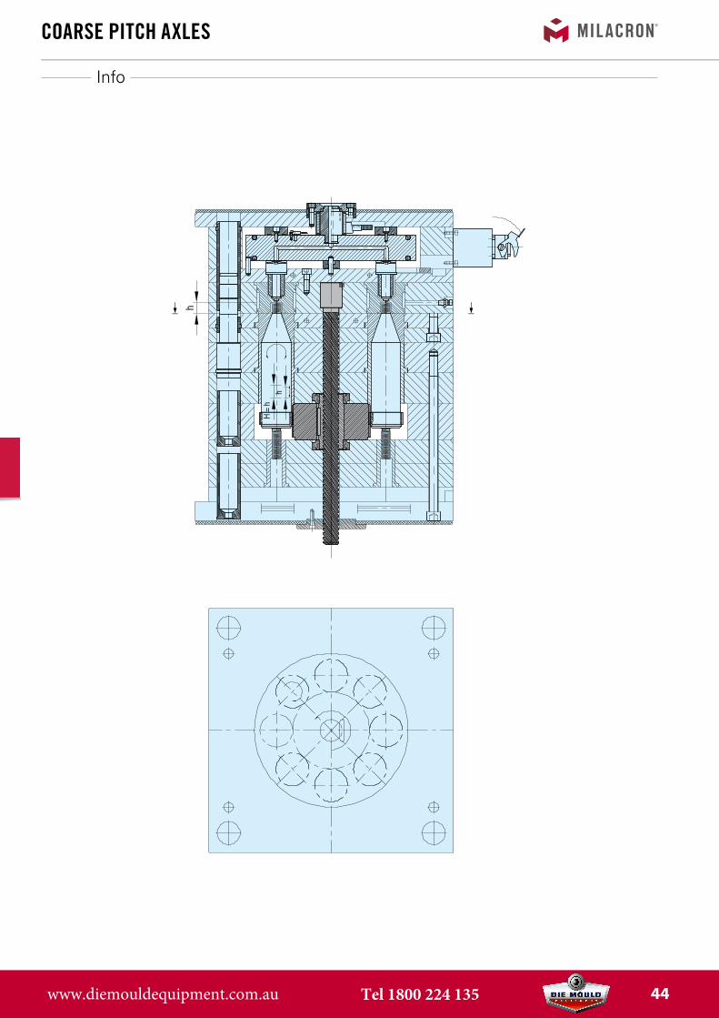
Info
Coarse PitCh axLes
www.diemouldequipment.com.au Tel 1800 224 135 44
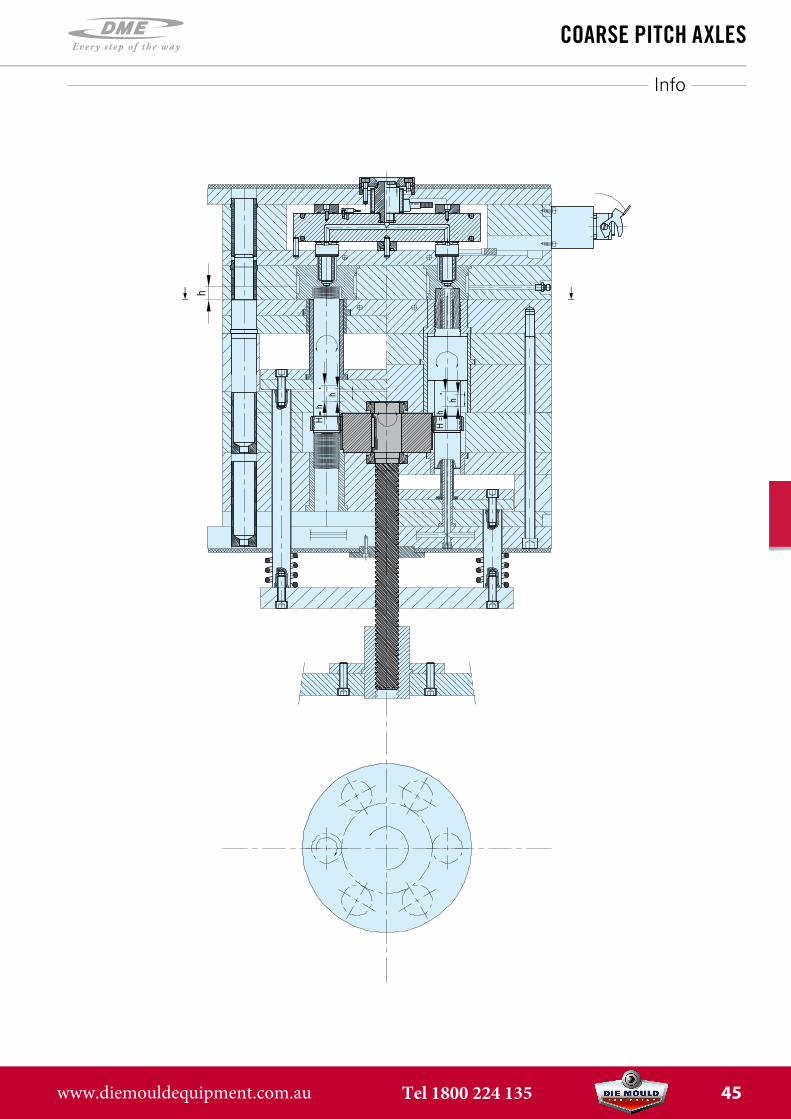
Info
Coarse PitCh axLes
www.diemouldequipment.com.au Tel 1800 224 135 45
HG
heLiCaL gear
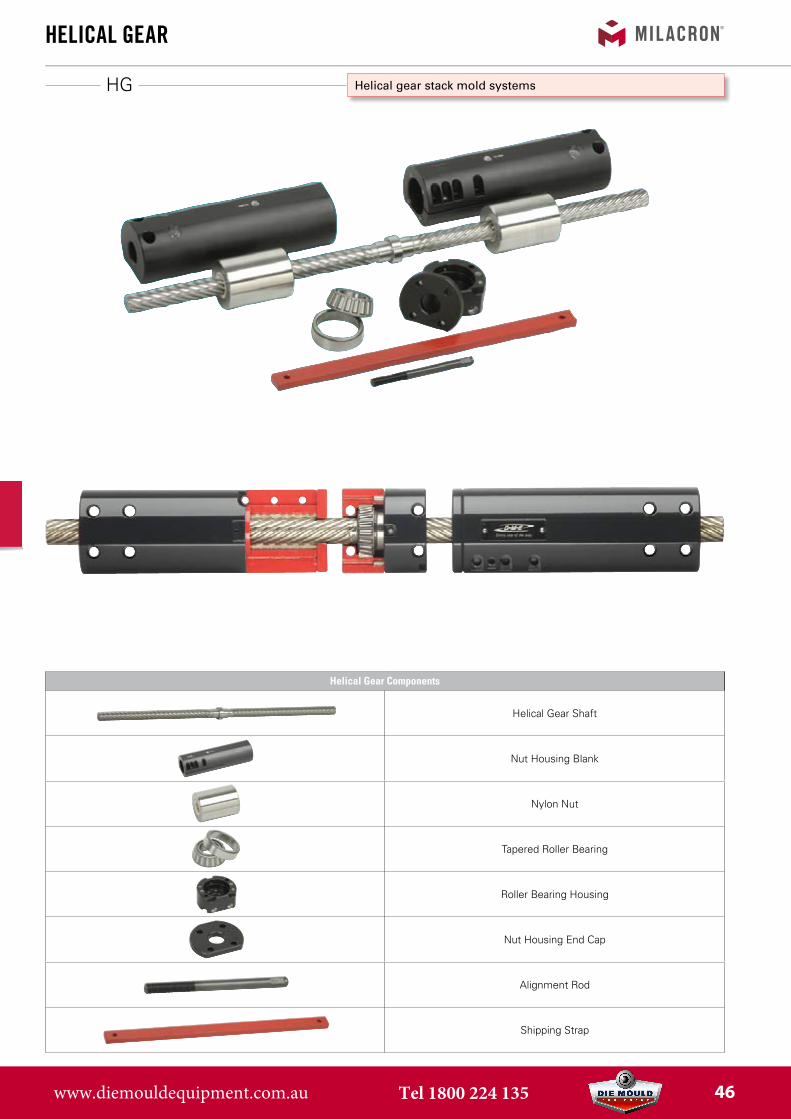
Helical gear stack mold systems
Helical Gear Components
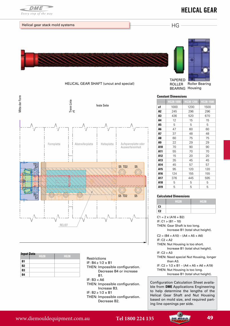
Helical Gear Shaft
Nut Housing Blank
Nylon Nut
Tapered Roller Bearing
Roller Bearing Housing
Nut Housing End Cap
Alignment Rod
Shipping Strap
www.diemouldequipment.com.au Tel 1800 224 135 46
HG
heLiCaL gear
Helical gear stack mold systems
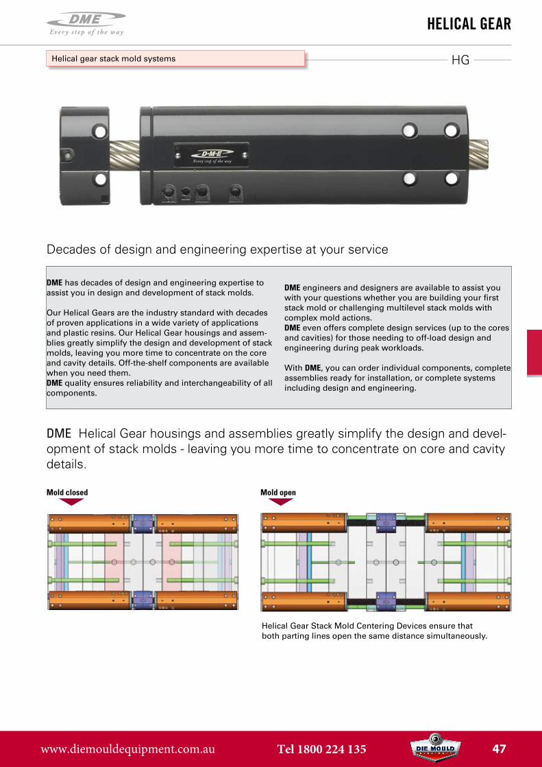
DME has decades of design and engineering expertise to assist you in design and development of stack molds.
Our Helical Gears are the industry standard with decades of proven applications in a wide variety of applications and plastic resins. Our Helical Gear housings and assem-blies greatly simplify the design and development of stack molds, leaving you more time to concentrate on the core and cavity details. Off-the-shelf components are available when you need them.DME quality ensures reliability and interchangeability of all components.
DME engineers and designers are available to assist you with your questions whether you are building your first stack mold or challenging multilevel stack molds with complex mold actions.DME even offers complete design services (up to the cores and cavities) for those needing to off-load design and engineering during peak workloads.
With DME, you can order individual components, complete assemblies ready for installation, or complete systems including design and engineering.
Mold closed Mold open
Helical Gear Stack Mold Centering Devices ensure that both parting lines open the same distance simultaneously.
DME Helical Gear housings and assemblies greatly simplify the design and devel-opment of stack molds - leaving you more time to concentrate on core and cavity details.
Decades of design and engineering expertise at your service
www.diemouldequipment.com.au Tel 1800 224 135 47
HG
heLiCaL gear
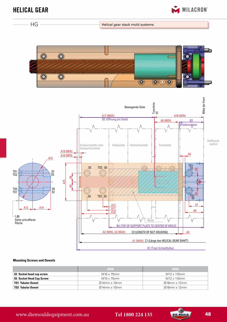
Helical gear stack mold systems
(Öffnung pro Seite)
(TOP OF SUPPORT PLATE TO CENTER OF MOLD)
A17 (MAX)
A2 (MIN), A3 (MAX)
(Plattenstärke)
S5TD2
TD2 S5
S5
S5
C2 (LENGTH OF NUT HOUSING)
A12A11A10
A4
A6
A7
A9
B1 (Total Schleißhöhe)
A15
A8 (MIN)
A9
A9A9
B4
Relief
S2
B3
A15
A13 A14
B2
Abstreiferplatte Formplatte
Bewegende Seite
Tren
nlin
ie
#2A5A18 (MIN)
A19 (MIN)
A16 (MIN)
Mitt
e de
r For
m
TD1TD2 S5
S5S2
TD2TD1
TD1S2
TD1S2
1.00Siehe schraffierteFläche
Aufspannplatte oderAuswerfereinheit
HalteplatteHeißkanal-
system
A1 (MAX)
S5 S5
S5 S5
TD2
TD2
C1 (Länge des HELICAL GEAR SHAFT)
RELIEF
Formplatte Abstreiferplatte
feste Seite
Tren
n Lin
ie
#1Mitt
e de
r For
m
TD1S2
TD1S2
Halteplatte Aufspannplatte oderAuswerfereinheit
HG28 HG38
S2 Socket head cap screw M10 x 75mm M12 x 110mmS5 Socket Head Cap Screw M10 x 75mm M12 x 110mmTD1 Tubular Dowel Ø14mm x 10mm Ø18mm x 12mmTD2 Tubular Dowel Ø14mm x 10mm Ø18mm x 12mm
Mounting Screws and Dowels
www.diemouldequipment.com.au Tel 1800 224 135 48
HG
HG28-1000 HG38-1200 HG38-1500
a1 1000 1200 1500A2 245 296 296A3 436 520 670A4 12 15 15A5 5 5 5A6 47 60 60A7 37 48 48A8 60 75 75A9 22 29 29A10 70 90 90A11 55 70 70A12 15 20 20A13 35 45 45A14 45 57 57A15 95 120 120A16 124 155 155A17 376 445 595A18 5 5 5A19 5 5 5
HG28 HG38
B1B2B3B4
HG28 HG38
C1C2
heLiCaL gear
Helical gear stack mold systems
Configuration Calculation Sheet availa-ble from DME Applications Engineering to help determine the lengths of the Helical Gear Shaft and Nut Housing based on mold size, and required part-ing line openings per side.
Constant Dimensions
RestrictionsIF: B4 1/2 x B1THEN: Impossible configuration.
Decrease B4 or increase B1.
IF: B3 < A6THEN: Impossible configuration.
Increase B3.IF: B2 1/2 x B1THEN: Impossible configuration.
Decrease B2.
Input Data
C1 = 2 x (A16 + B2)IF: C1 > (B1 – 10) THEN: Gear Shaft is too long.
Increase B1 (total shut height).
C2 = (B4 + A10) – (A4 + A5 + A6)IF: C2 < A2 THEN: Nut Housing is too short.
Increase B1 (total shut height).IF: C2 > A3THEN: Need special Nut Housing, longer
than A3.IF: C2 > 1/2 x B1 – (A4 + A5 + A6 + A19)THEN: Nut Housing is too long.
Increase B1 (total shut height).
Calculated Dimensions
(Öffnung pro Seite)
(TOP OF SUPPORT PLATE TO CENTER OF MOLD)
A17 (MAX)
A2 (MIN), A3 (MAX)
(Plattenstärke)
S5TD2
TD2 S5
S5
S5
C2 (LENGTH OF NUT HOUSING)
A12A11A10
A4
A6
A7
A9
B1 (Total Schleißhöhe)
A15
A8 (MIN)
A9
A9A9
B4
Relief
S2
B3
A15
A13 A14
B2
Abstreiferplatte Formplatte
Bewegende Seite
Tren
nlin
ie#2
A5A18 (MIN)A19 (MIN)
A16 (MIN)
Mitt
e de
r For
m
TD1TD2 S5
S5S2
TD2TD1
TD1S2
TD1S2
1.00Siehe schraffierteFläche
Aufspannplatte oderAuswerfereinheit
HalteplatteHeißkanal-
system
A1 (MAX)
S5 S5
S5 S5
TD2
TD2
C1 (Länge des HELICAL GEAR SHAFT)
RELIEF
Formplatte Abstreiferplatte
feste Seite
Tren
n Lin
ie
#1Mitt
e de
r For
m
TD1S2
TD1S2
Halteplatte Aufspannplatte oderAuswerfereinheit
Roller Bearing Housing
HELICAL GEAR SHAFT (uncut and special)TAPERED ROLLER BEARING
www.diemouldequipment.com.au Tel 1800 224 135 49
AEP
ejeCtion ControL
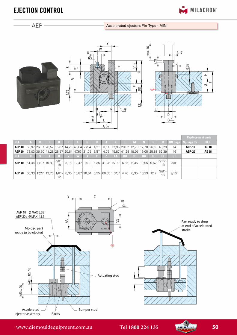
Accelerated ejectors Pin-Type - MINI
Molded partready to be ejected
Accelerated ejector assembly Racks
Bumper stud
Actuating stud
Part ready to drop at end of accelerated stroke
Replacement partsREF A B C D E F G H J K L M N P Q HH Cogs Springs for REFAEP 10 53,97 26,97 28,57 15,87 14,28 40,64 27,94 1/2” 3,17 12,95 28,02 12,70 12,70 26,16 45,29 14 AEP-10 AE 18AEP 20 73,03 36,50 41,28 28,57 20,64 47,63 31,75 5/8” 4,75 15,87 41,28 19,05 19,05 25,81 52,39 16 AEP-20 AE 28REF R S T U V W X Y Z AA BB CC DD EE FF GG
AEP 10 51,44 13,97 10,80 5/8”-18 3,18 12,47 14,0 6,35 41,28 15/16” 6,35 6,35 19,05 9,52 5/16”-
18 3/8”
AEP 20 60,33 17,27 12,701
1/8”-12
6,35 15,87 20,64 6,35 60,03 1 3/8” 4,76 6,35 18,29 12,7 3/8”-16 9/16”
www.diemouldequipment.com.au Tel 1800 224 135 50
AEB
ejeCtion ControL
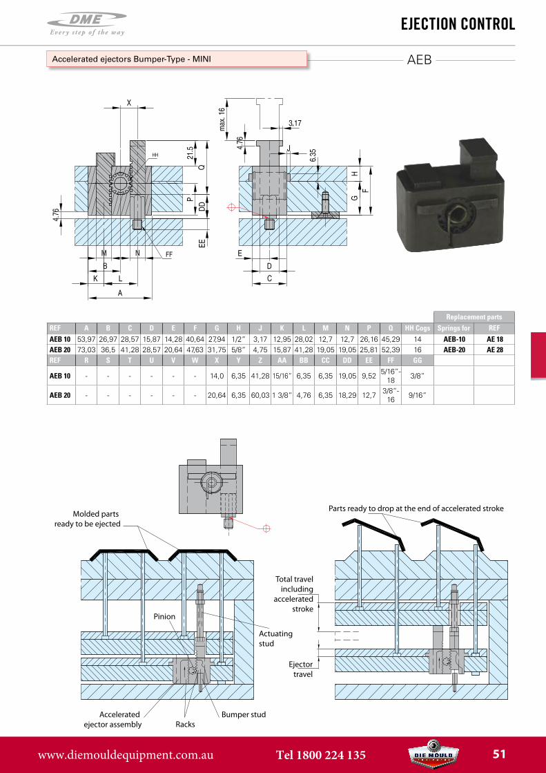
Accelerated ejectors Bumper-Type - MINI
Molded parts ready to be ejected
Bumper studRacks
Accelerated ejector assembly
Actuatingstud
Total travelincluding
acceleratedstroke
Ejectortravel
Parts ready to drop at the end of accelerated stroke
Pinion
Replacement partsREF A B C D E F G H J K L M N P Q HH Cogs Springs for REFAEB 10 53,97 26,97 28,57 15,87 14,28 40,64 27,94 1/2” 3,17 12,95 28,02 12,7 12,7 26,16 45,29 14 AEB-10 AE 18AEB 20 73,03 36,5 41,28 28,57 20,64 47,63 31,75 5/8” 4,75 15,87 41,28 19,05 19,05 25,81 52,39 16 AEB-20 AE 28REF R S T U V W X Y Z AA BB CC DD EE FF GG
AEB 10 - - - - - - 14,0 6,35 41,28 15/16” 6,35 6,35 19,05 9,52 5/16”-18 3/8”
AEB 20 - - - - - - 20,64 6,35 60,03 1 3/8” 4,76 6,35 18,29 12,7 3/8”-16 9/16”
www.diemouldequipment.com.au Tel 1800 224 135 51
ER
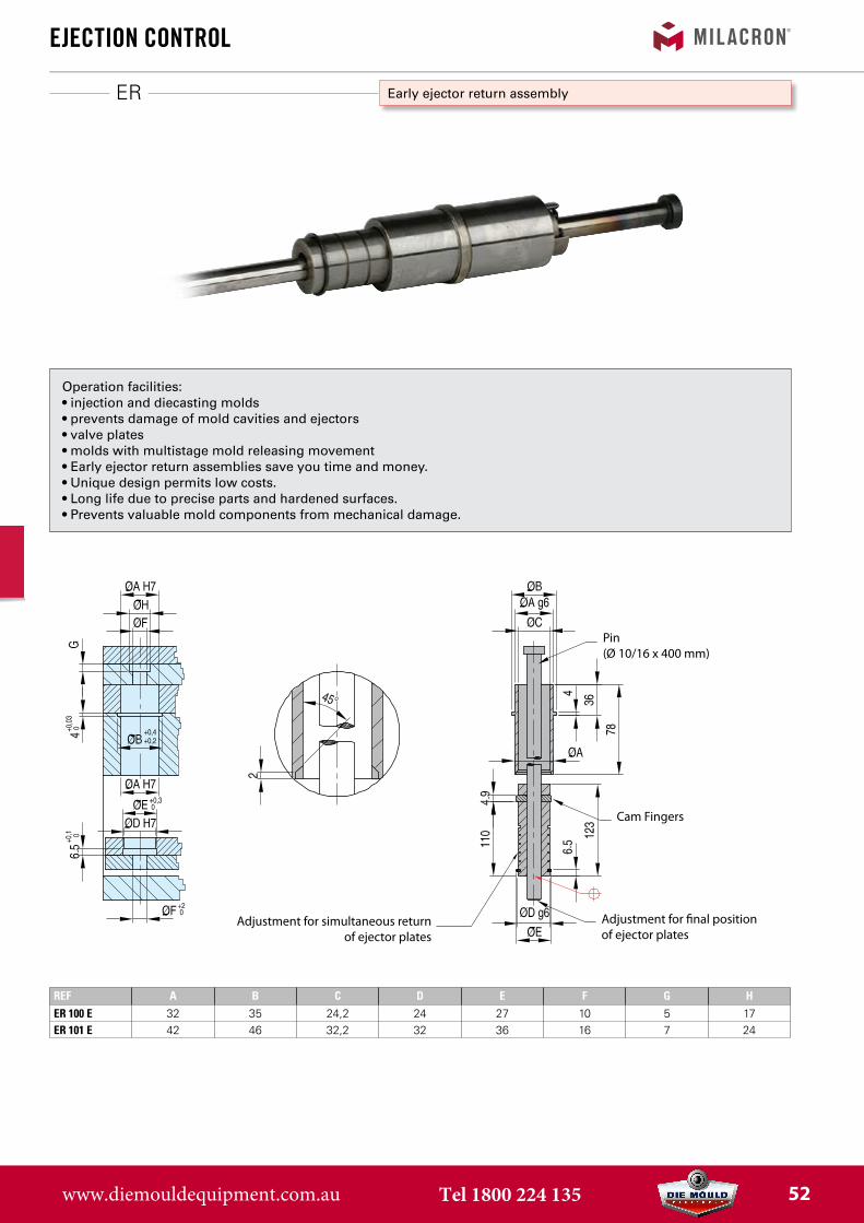
REF A B C D E F G HER 100 E 32 35 24,2 24 27 10 5 17ER 101 E 42 46 32,2 32 36 16 7 24
ejeCtion ControL
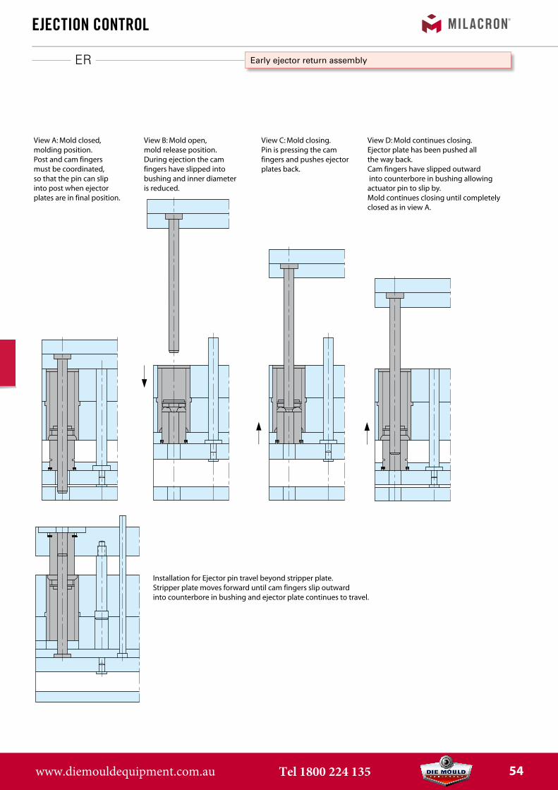
Early ejector return assembly
Operation facilities:• injection and diecasting molds• prevents damage of mold cavities and ejectors• valve plates• molds with multistage mold releasing movement• Early ejector return assemblies save you time and money.• Unique design permits low costs.• Long life due to precise parts and hardened surfaces.• Prevents valuable mold components from mechanical damage.
Pin(Ø 10/16 x 400 mm)
Cam Fingers
Adjustment for �nal position of ejector plates
Adjustment for simultaneous returnof ejector plates
www.diemouldequipment.com.au Tel 1800 224 135 52
ER
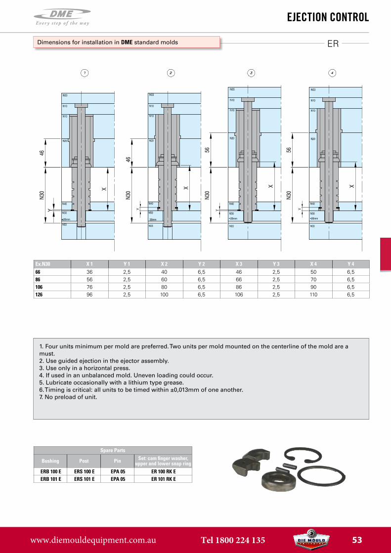
Ex.N30 X 1 Y 1 X 2 Y 2 X 3 Y 3 X 4 Y 466 36 2,5 40 6,5 46 2,5 50 6,586 56 2,5 60 6,5 66 2,5 70 6,5106 76 2,5 80 6,5 86 2,5 90 6,5126 96 2,5 100 6,5 106 2,5 110 6,5
ejeCtion ControL
Dimensions for installation in DME standard molds
1. Four units minimum per mold are preferred. Two units per mold mounted on the centerline of the mold are amust.2. Use guided ejection in the ejector assembly.3. Use only in a horizontal press.4. If used in an unbalanced mold. Uneven loading could occur.5. Lubricate occasionally with a lithium type grease.6. Timing is critical: all units to be timed within ±0,013mm of one another.7. No preload of unit.
Spare Parts
Bushing Post Pin Set: cam finger washer, upper and lower snap ring
ERB 100 E ERS 100 E EPA 05 ER 100 RK EERB 101 E ERS 101 E EPA 05 ER 101 RK E
www.diemouldequipment.com.au Tel 1800 224 135 53
ER
ejeCtion ControL
View A: Mold closed, molding position.Post and cam fingers must be coordinated, so that the pin can slip into post when ejector plates are in final position.
View B: Mold open, mold release position.During ejection the cam fingers have slipped into bushing and inner diameter is reduced.
View C: Mold closing.Pin is pressing the cam fingers and pushes ejector plates back.
View D: Mold continues closing.Ejector plate has been pushed all the way back.Cam fingers have slipped outward into counterbore in bushing allowing actuator pin to slip by.Mold continues closing until completely closed as in view A.
Installation for Ejector pin travel beyond stripper plate.Stripper plate moves forward until cam fingers slip outward into counterbore in bushing and ejector plate continues to travel.
Early ejector return assembly
www.diemouldequipment.com.au Tel 1800 224 135 54

AKO
ejeCtion ControL
Section A-A Section B-BApplication 1
Section B-BApplication 2
Section C-C
Note:Key ejector pin and limit possible
over travel of pin as required
Accelerated knock-outs10
mm
Stro
ke
Drilled and counterbored4x SHCS 1/4” or M6
Ø9.52 DowelSection A-A
View P
The accelerated knock-outs are simple in design, using a pivot-type motion for accelerated ejection. Mechanical advantage is 2:1. They will accommodate ejector pins up to 9,5mm in diameter. (Pins with head diameters over 15,8mm can be ground down to fit). Simplicity of design permits accelerated knock-outs to be either inserted into the ejector plate (as shown below) or top mounted, depending on space available for the ejection movement.
www.diemouldequipment.com.au Tel 1800 224 135 55
Info PSR-PSM-MRT-SRTM
sLide retainers
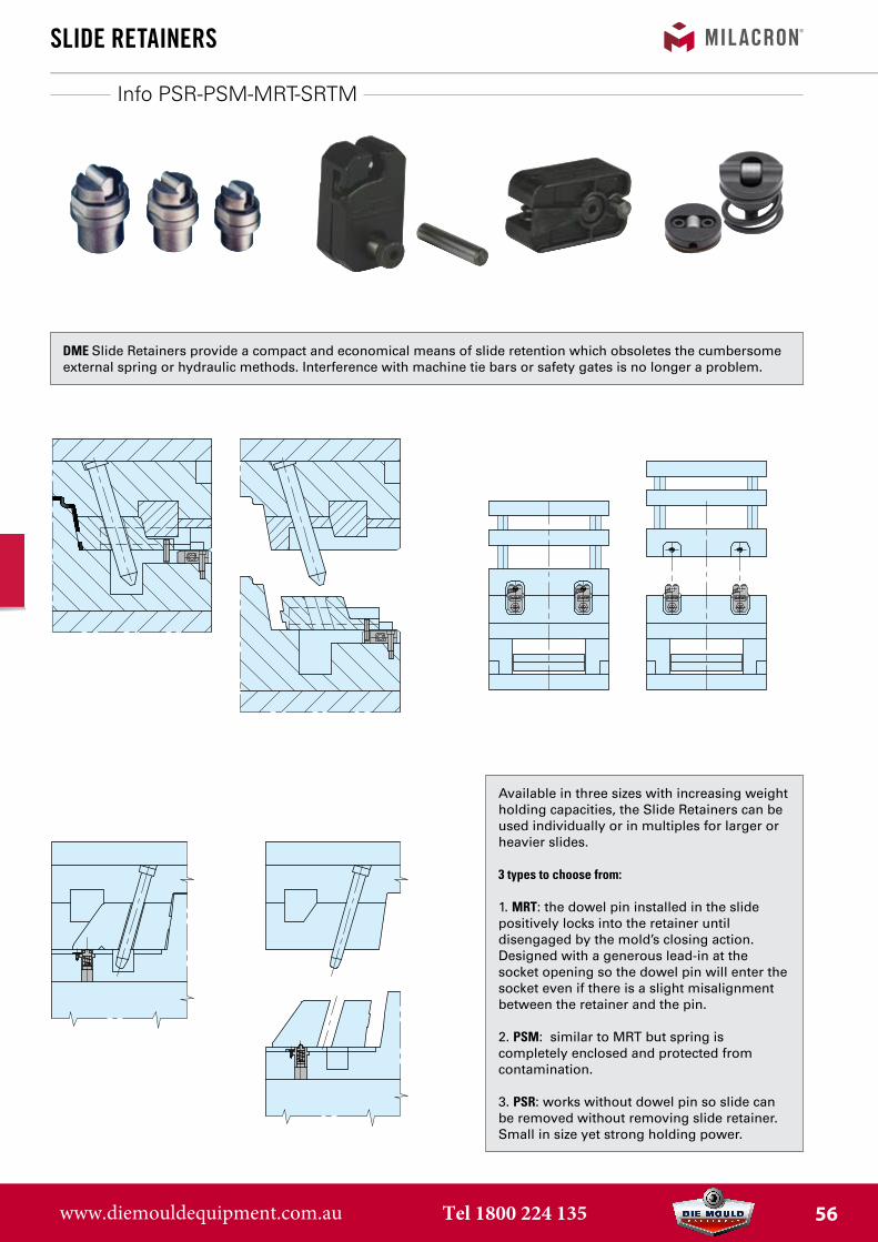
Available in three sizes with increasing weight holding capacities, the Slide Retainers can be used individually or in multiples for larger or heavier slides.
3 types to choose from:
1. MRT: the dowel pin installed in the slidepositively locks into the retainer untildisengaged by the mold’s closing action.Designed with a generous lead-in at thesocket opening so the dowel pin will enter thesocket even if there is a slight misalignmentbetween the retainer and the pin.
2. PSM: similar to MRT but spring iscompletely enclosed and protected fromcontamination.
3. PSR: works without dowel pin so slide canbe removed without removing slide retainer.Small in size yet strong holding power.
DME Slide Retainers provide a compact and economical means of slide retention which obsoletes the cumbersome external spring or hydraulic methods. Interference with machine tie bars or safety gates is no longer a problem.
www.diemouldequipment.com.au Tel 1800 224 135 56
PSR
sLide retainers
Wear plate
Installation instructions
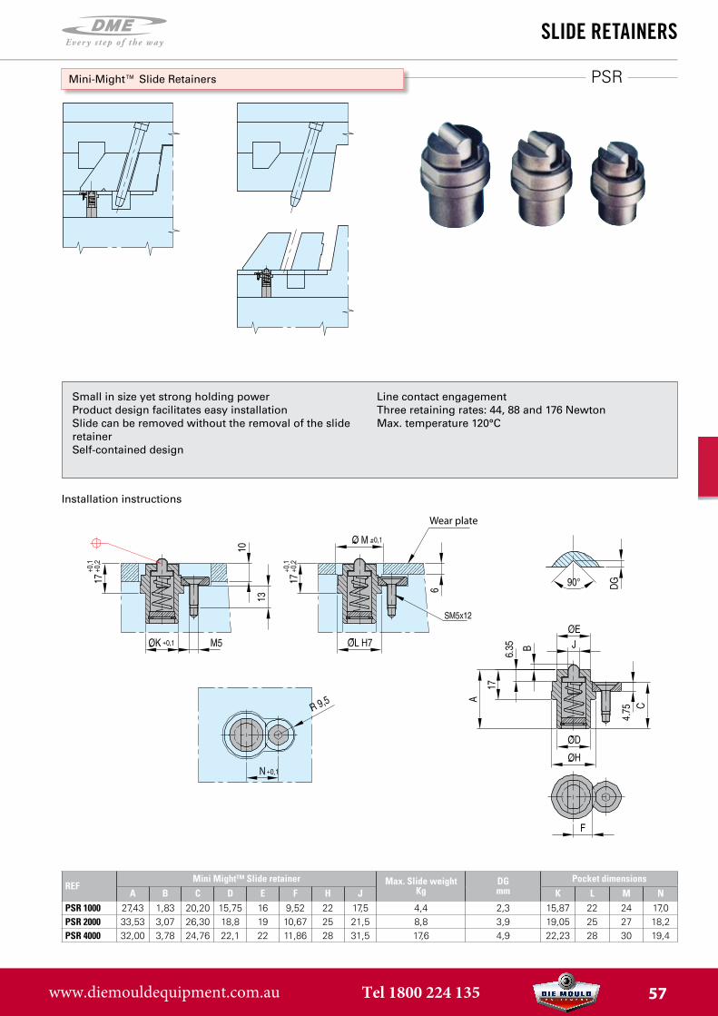
Mini-Might™ Slide Retainers
Small in size yet strong holding powerProduct design facilitates easy installationSlide can be removed without the removal of the slide retainerSelf-contained design
Line contact engagementThree retaining rates: 44, 88 and 176 NewtonMax. temperature 120°C
REFMini Might™ Slide retainer Max. Slide weight
KgDGmm
Pocket dimensionsA B C D E F H J K L M N
PSR 1000 27,43 1,83 20,20 15,75 16 9,52 22 17,5 4,4 2,3 15,87 22 24 17,0PSR 2000 33,53 3,07 26,30 18,8 19 10,67 25 21,5 8,8 3,9 19,05 25 27 18,2PSR 4000 32,00 3,78 24,76 22,1 22 11,86 28 31,5 17,6 4,9 22,23 28 30 19,4
www.diemouldequipment.com.au Tel 1800 224 135 57
MRT
sLide retainers
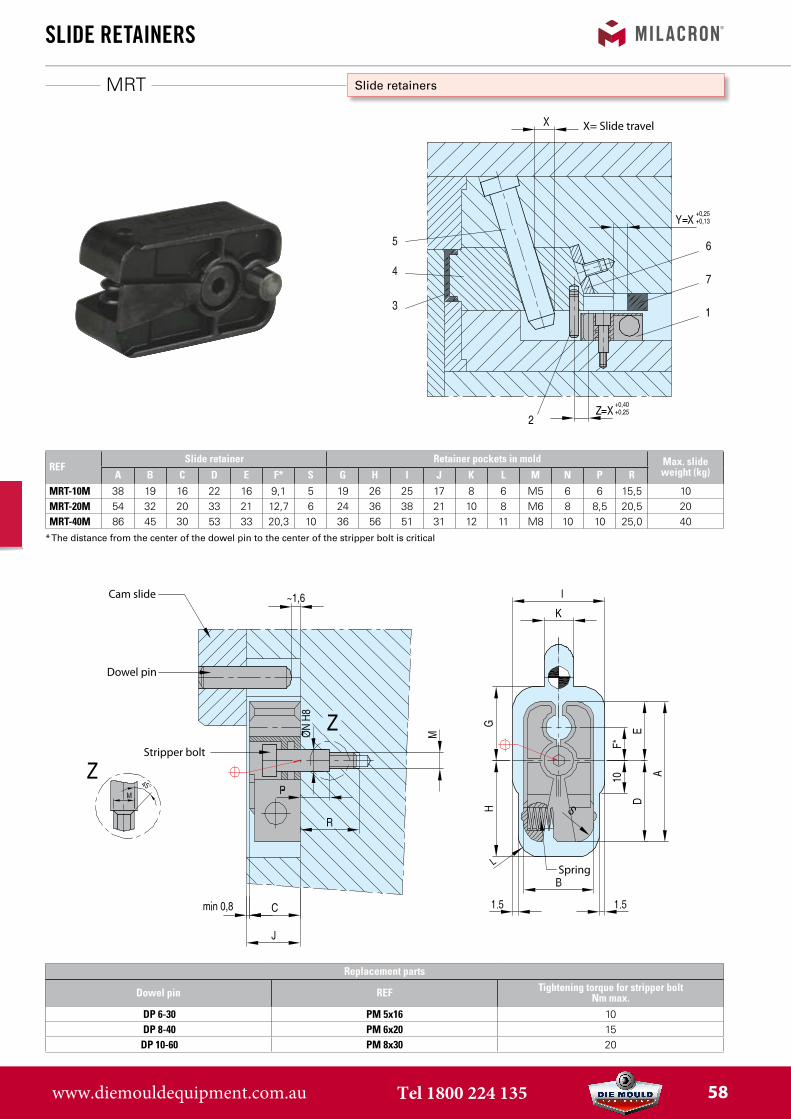
Slide retainers
X= Slide travel
REFSlide retainer Retainer pockets in mold Max. slide
weight (kg)A B C D E F* S G H I J K L M N P RMRT-10M 38 19 16 22 16 9,1 5 19 26 25 17 8 6 M5 6 6 15,5 10MRT-20M 54 32 20 33 21 12,7 6 24 36 38 21 10 8 M6 8 8,5 20,5 20MRT-40M 86 45 30 53 33 20,3 10 36 56 51 31 12 11 M8 10 10 25,0 40
* The distance from the center of the dowel pin to the center of the stripper bolt is critical
Replacement parts
Dowel pin REF Tightening torque for stripper bolt Nm max.
DP 6-30 PM 5x16 10DP 8-40 PM 6x20 15
DP 10-60 PM 8x30 20
Cam slide
Dowel pin
Stripper bolt
Spring
www.diemouldequipment.com.au Tel 1800 224 135 58
PSM
sLide retainers
Slide retainers
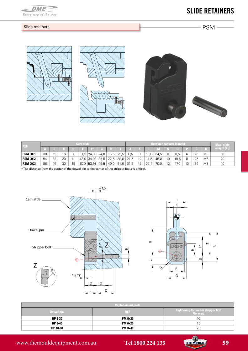
REFCam slide Retainer pockets in mold Max. slide
weight (kg)A B C D E F* G H I J K L M N O P Q RPSM 0001 38 19 16 7 31,5 24,89 24,0 15,5 25,5 17,5 8 10,0 34,5 8 8,5 6 20 M5 10PSM 0002 54 32 20 11 43,0 34,93 36,5 22,5 38,0 21,5 10 14,5 46,0 10 10,5 8 25 M6 20PSM 0003 86 45 30 19 67,0 53,98 49,5 40,0 51,0 31,5 12 22,5 70,0 12 17,0 10 35 M8 40
* The distance from the center of the dowel pin to the center of the stripper bolts is critical.
Replacement parts
Dowel pin REF Tightening torque for stripper bolt Nm max.
DP 6-30 PM 5x20 10DP 8-40 PM 6x25 15
DP 10-60 PM 8x40 20
Cam slide
Dowel pin
Stripper bolt
www.diemouldequipment.com.au Tel 1800 224 135 59
SRTM
sLide retainers
Slide retainers
HD
L
T
D
G
J
E SL L
R90°
C
M K
LR
M
D
L LR
90°
Cleat bottom viewNote: The cleat screws arein a dif ferent location thanthe slide retainer screws .
M K
1/4" or 6mmnominal wear plate
D D
Do not chamfer hole*
Cleat bottom viewNote: The cleat screws arein a dif ferent location thanthe slide retainer screws
Retainer& Cleat .015" Max
Chamfer
Slide Retainerscrew locations
6mmnominal wear plateDo not chamfer hole*
6mmnominal wearplate
Do not chamferhole*
HD
L
T
D
G
J
E SL L
R90°
C
M K
LR
M
D
L
LR
90°
Cleat bottom viewNote: The cleat screws arein a dif ferent location thanthe slide retainer screws .
M
K
1/4" or 6mmnominal wear plate
D
D
Do not chamfer hole*
Cleat bottom viewNote: The cleat screws arein a dif ferent location thanthe slide retainer screws
Retainer& Cleat .015" Max
Chamfer
Slide Retainerscrew locations
6mmnominal wear plateDo not chamfer hole*
6mmnominal wearplate
Do not chamferhole*
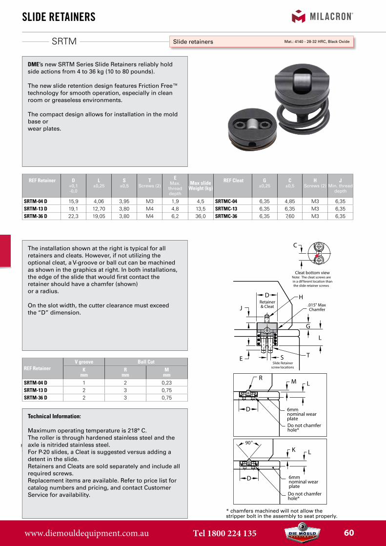
DME’s new SRTM Series Slide Retainers reliably hold side actions from 4 to 36 kg (10 to 80 pounds).
The new slide retention design features Friction Free™ technology for smooth operation, especially in clean room or greaseless environments.
The compact design allows for installation in the mold base orwear plates.
The installation shown at the right is typical for all retainers and cleats. However, if not utilizing the optional cleat, a V-groove or ball cut can be machined as shown in the graphics at right. In both installations, the edge of the slide that would first contact the retainer should have a chamfer (shown)or a radius.
On the slot width, the cutter clearance must exceedthe “D” dimension.
Technical Information:
Maximum operating temperature is 218° C.The roller is through hardened stainless steel and theaxle is nitrided stainless steel.For P-20 slides, a Cleat is suggested versus adding a detent in the slide.Retainers and Cleats are sold separately and include all required screws.Replacement items are available. Refer to price list for catalog numbers and pricing, and contact Customer Service for availability.
REF Retainer D+0,1-0,0
L±0,25
S±0,5
TScrews (2)
EMax.
thread depth
Max slide Weight (kg)
REF Cleat G±0,25
C±0,5
HScrews (2)
JMin. thread
depth
SRTM-04 D 15,9 4,06 3,95 M3 1,9 4,5 SRTMC-04 6,35 4,85 M3 6,35SRTM-13 D 19,1 12,70 3,80 M4 4,8 13,5 SRTMC-13 6,35 6,35 M3 6,35SRTM-36 D 22,3 19,05 3,80 M4 6,2 36,0 SRTMC-36 6,35 7,60 M3 6,35
REF RetainerV groove Ball Cut
Kmm
Rmm
Mmm
SRTM-04 D 1 2 0,23SRTM-13 D 2 3 0,75SRTM-36 D 2 3 0,75
* chamfers machined will not allow thestripper bolt in the assembly to seat properly.
Mat.: 4140 - 28-32 HRC, Black Oxide
www.diemouldequipment.com.au Tel 1800 224 135 60
FP
FriCtion PuLLers
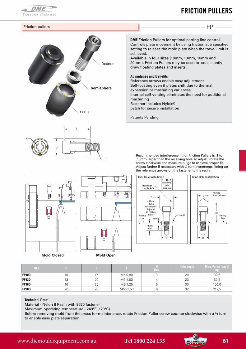
DME Friction Pullers for optimal parting line control. Controls plate movement by using friction at a specified setting to release the mold plate when the travel limit is achieved.Available in four sizes (10mm, 13mm, 16mm and 20mm), Friction Pullers may be used to consistently draw floating plates and inserts.
Advantages and BenefitsReference arrows enable easy adjustmentSelf-locating even if plates shift due to thermal expansion or machining variancesInternal self-venting eliminates the need for additional machiningFastener includes Nylok® patch for secure installation
Patents Pending
Technical Data:Material - Nylon 6 Resin with 8620 fastenerMaximum operating temperature - 248°F (120°C)Before removing mold from the press for maintenance, rotate Friction Puller screw counter-clockwise with a ¾ turn to enable easy plate separation
Friction pullers
2mm R
T
D
D D
H
3mm
10mmmin
D
D
D D
DD DD
L
HD
Thru Hole Installation Blind Hole Installation
Hole finish= m Ra .4-.16
+.10mm+.15mm
InterferenceAdjusted
on FrictionPuller
ReceivingHole
Diameter
FloatingPlate or Insert
Mold Closed Mold Open
Parting Line
Parting Line
REF D L T H Hex
Hole depth Max. Force (each) kg
FP10D 10 17 M5-0,80 3 20 32,5FP13D 13 20 M6-1,00 4 23 62,5FP16D 16 25 M8-1,25 5 30 150,0FP20D 20 28 M10-1,50 6 32 212,5
Recommended interference fit for Friction Pullers is .1 to .15mm larger than the receiving hole. To adjust, rotate the screw clockwise and measure bulge to achieve proper fit. Adjust further if necessary with ¼ turn increments, lining up the reference arrows on the fastener to the resin.
fastner
hemisphere
resin
www.diemouldequipment.com.au Tel 1800 224 135 61