Embed Size (px)
Citation preview
POWERLINK Dynamometer for Construction Machinery Transmission, Gearbox, Torque Converter and Hydraulic Transmission Test
Configuration reference
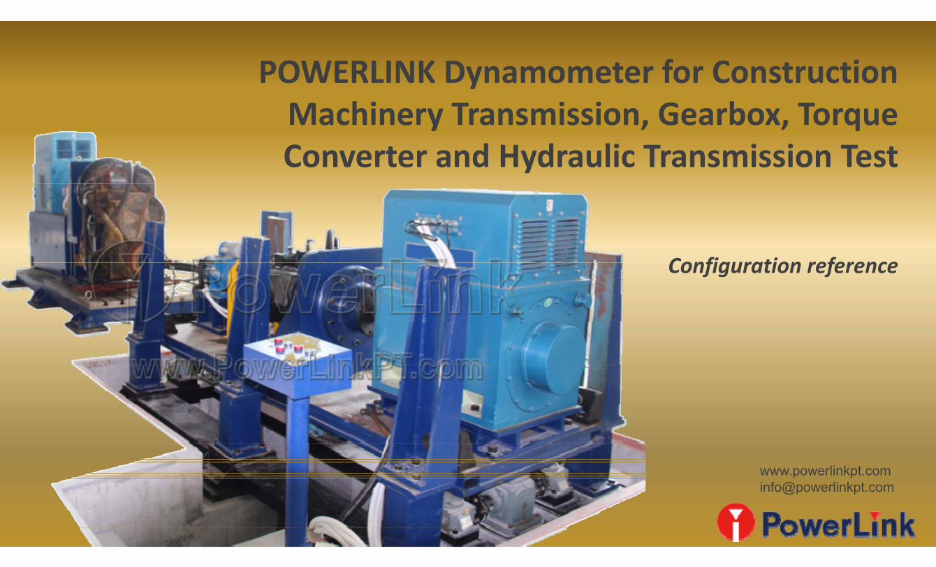
1. Low‐cost gearbox and transmission test configuration:
The purpose of using accompanied gearbox (accelerated gearbox) is mainly to increase the speedand reduce the test bench cost. After engine driving gearbox, the output speed will become verylow. In case of constant power, the lower the speed, the greater the torque. Assuming that the gearratio of the test gearbox may be high, the output torque may be large. The low speed and hightorque load is expensive and also hard to find the right one. So the final speed must rise up. Theaccompanied gearbox can take use the test gearbox in reverse to reduce the test bench cost.
Driven by engine, eddy current dynamometer as the load
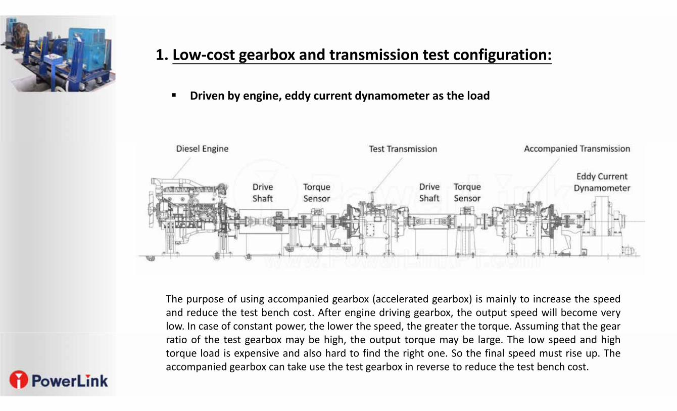
1. Low‐cost gearbox and transmission test configuration: Driven by engine, eddy current
dynamometer as the load
Engine
Eddy Current BrakeGearbox Oil Temperature Control Device
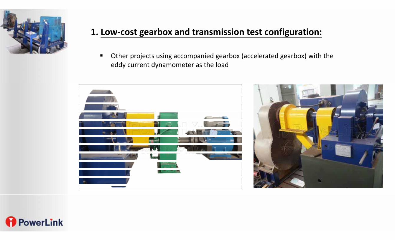
1. Low‐cost gearbox and transmission test configuration:
Other projects using accompanied gearbox (accelerated gearbox) with the eddy current dynamometer as the load
• Electric dynamometer as the drive and the load
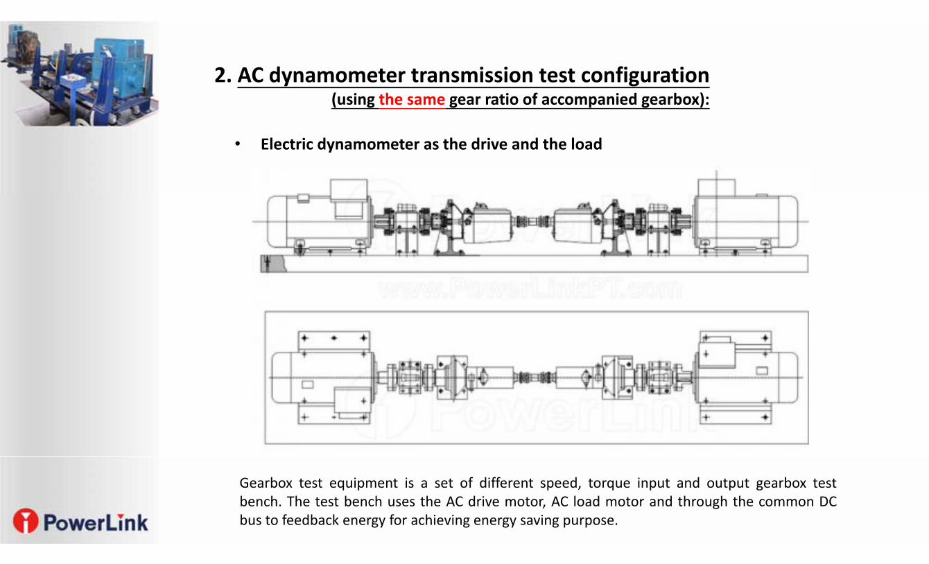
Gearbox test equipment is a set of different speed, torque input and output gearbox testbench. The test bench uses the AC drive motor, AC load motor and through the common DCbus to feedback energy for achieving energy saving purpose.
2. AC dynamometer transmission test configuration (using the same gear ratio of accompanied gearbox):
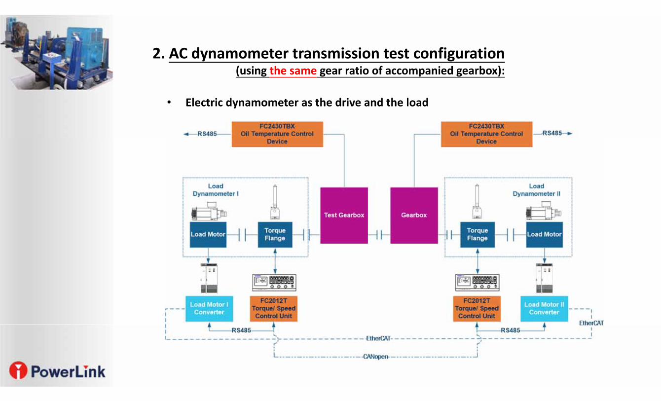
• Electric dynamometer as the drive and the load
2. AC dynamometer transmission test configuration (using the same gear ratio of accompanied gearbox):
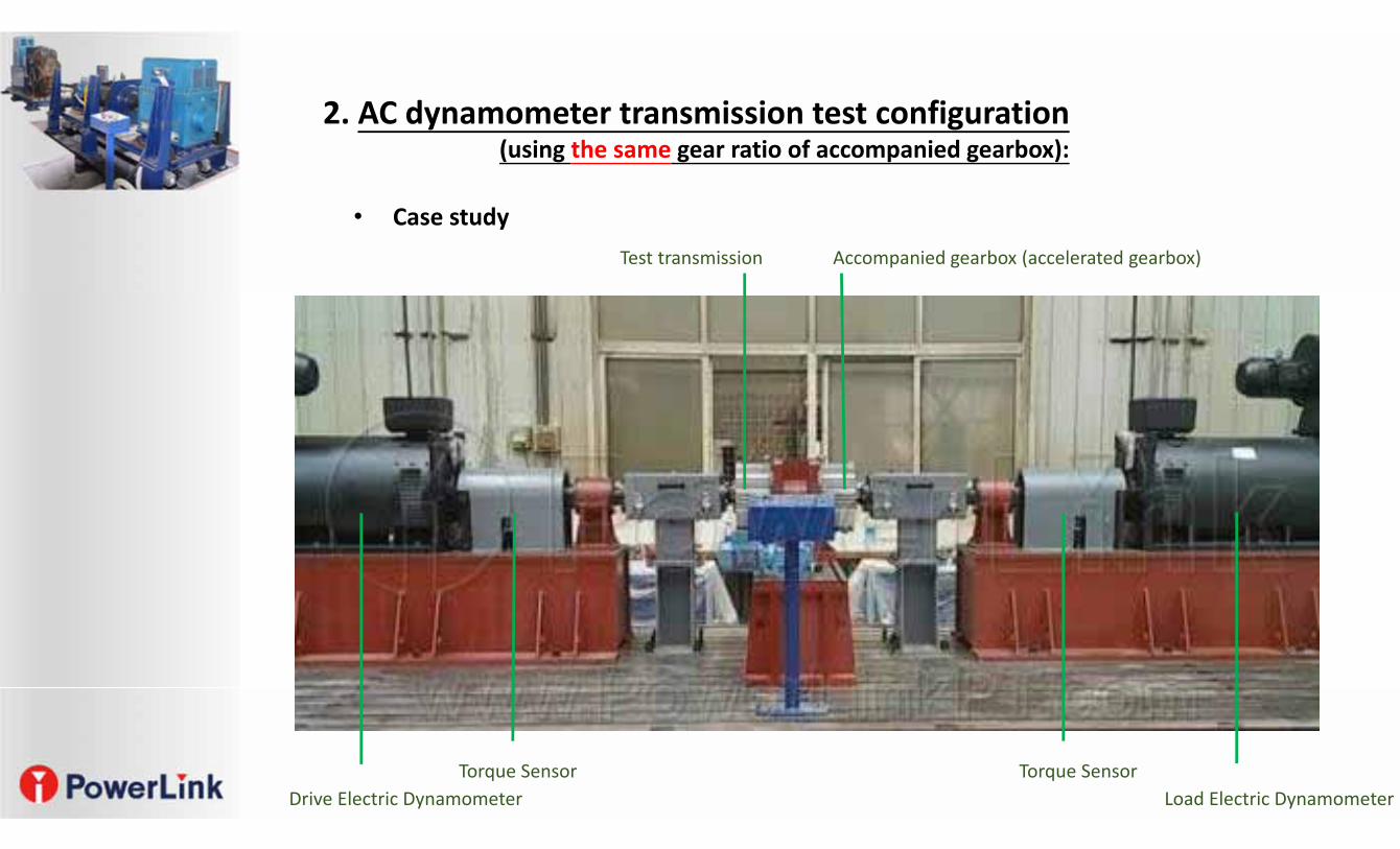
Drive Electric Dynamometer Load Electric DynamometerTorque Sensor Torque Sensor
Test transmission Accompanied gearbox (accelerated gearbox)
• Case study
2. AC dynamometer transmission test configuration (using the same gear ratio of accompanied gearbox):
• Electric dynamometer as the drive and the load
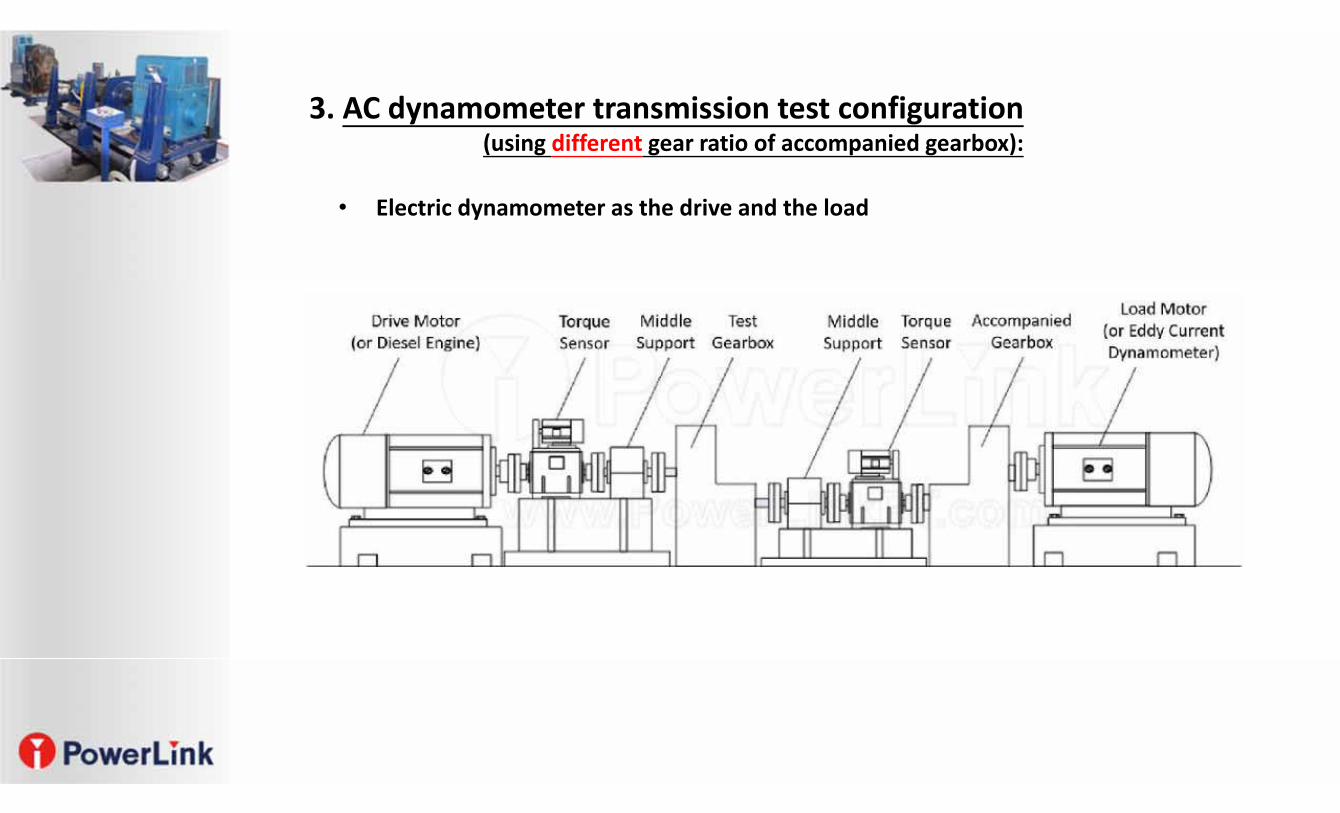
3. AC dynamometer transmission test configuration (using different gear ratio of accompanied gearbox):
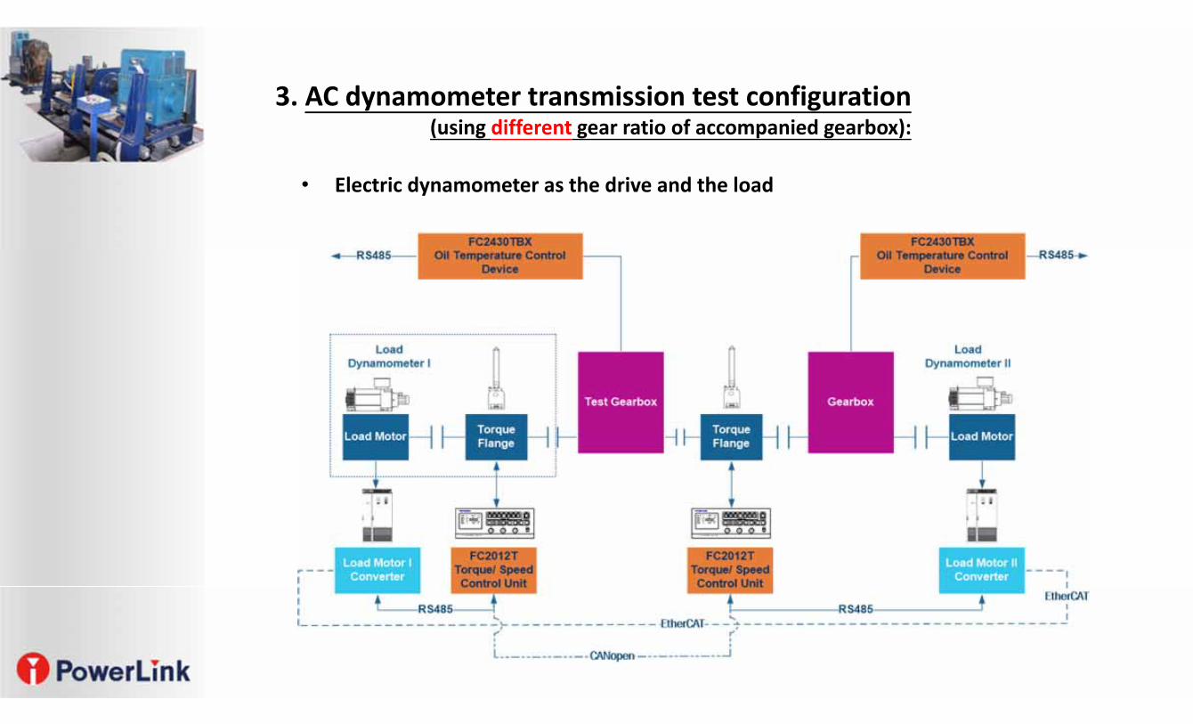
• Electric dynamometer as the drive and the load
3. AC dynamometer transmission test configuration (using different gear ratio of accompanied gearbox):
Drive Electric Dynamometer Load Electric Dynamometer
Torque Sensor Torque Sensor
Test transmission Accompanied gearbox (Accelerated gearbox)
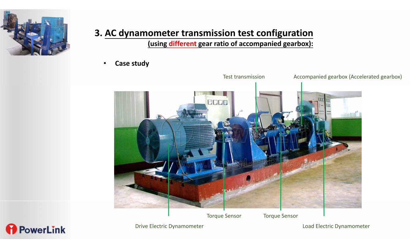
• Case study
3. AC dynamometer transmission test configuration (using different gear ratio of accompanied gearbox):
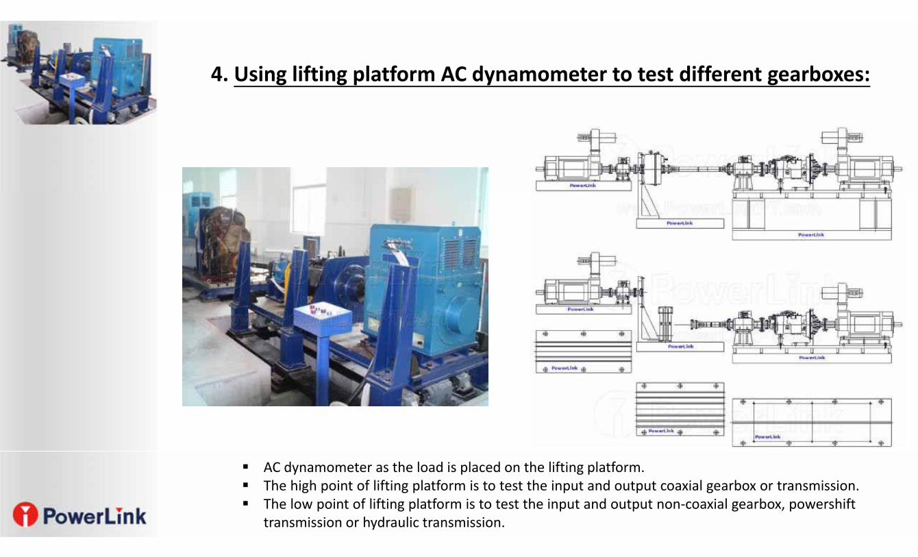
4. Using lifting platform AC dynamometer to test different gearboxes:
AC dynamometer as the load is placed on the lifting platform. The high point of lifting platform is to test the input and output coaxial gearbox or transmission. The low point of lifting platform is to test the input and output non‐coaxial gearbox, powershift
transmission or hydraulic transmission.
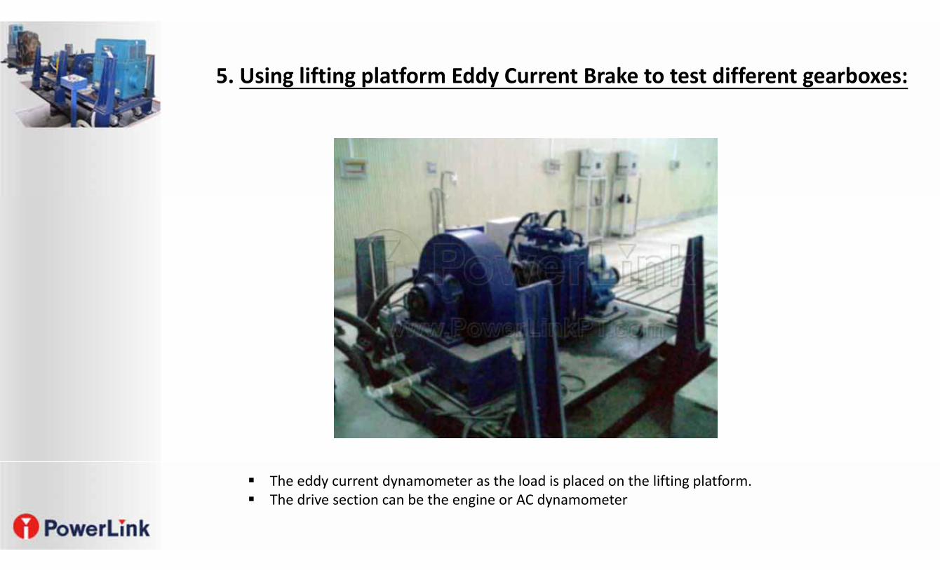
5. Using lifting platform Eddy Current Brake to test different gearboxes:
The eddy current dynamometer as the load is placed on the lifting platform. The drive section can be the engine or AC dynamometer
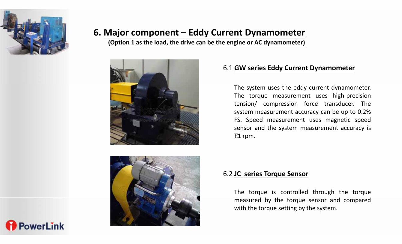
6.1 GW series Eddy Current Dynamometer
6.2 JC series Torque Sensor
The system uses the eddy current dynamometer.The torque measurement uses high‐precisiontension/ compression force transducer. Thesystem measurement accuracy can be up to 0.2%FS. Speed measurement uses magnetic speedsensor and the system measurement accuracy is±1 rpm.
The torque is controlled through the torquemeasured by the torque sensor and comparedwith the torque setting by the system.
6. Major component – Eddy Current Dynamometer (Option 1 as the load, the drive can be the engine or AC dynamometer)
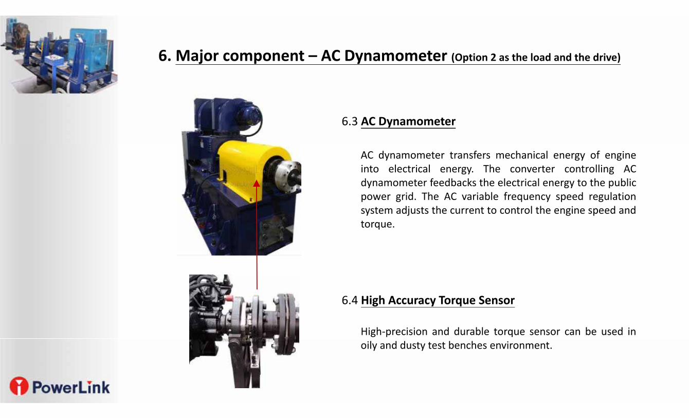
6.3 AC Dynamometer
6.4 High Accuracy Torque Sensor
AC dynamometer transfers mechanical energy of engineinto electrical energy. The converter controlling ACdynamometer feedbacks the electrical energy to the publicpower grid. The AC variable frequency speed regulationsystem adjusts the current to control the engine speed andtorque.
High‐precision and durable torque sensor can be used inoily and dusty test benches environment.
6. Major component – AC Dynamometer (Option 2 as the load and the drive)
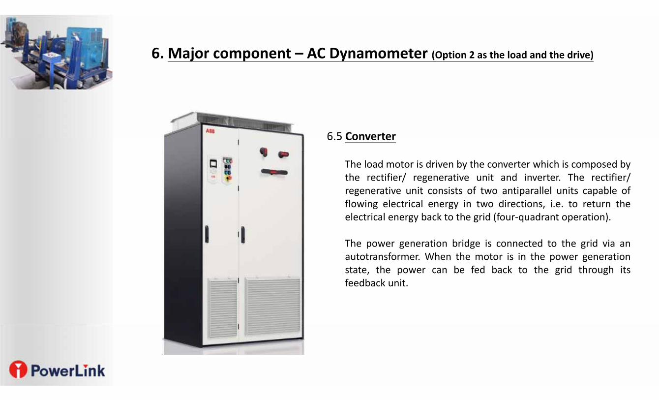
6.5 Converter
The load motor is driven by the converter which is composed bythe rectifier/ regenerative unit and inverter. The rectifier/regenerative unit consists of two antiparallel units capable offlowing electrical energy in two directions, i.e. to return theelectrical energy back to the grid (four‐quadrant operation).
The power generation bridge is connected to the grid via anautotransformer. When the motor is in the power generationstate, the power can be fed back to the grid through itsfeedback unit.
6. Major component – AC Dynamometer (Option 2 as the load and the drive)
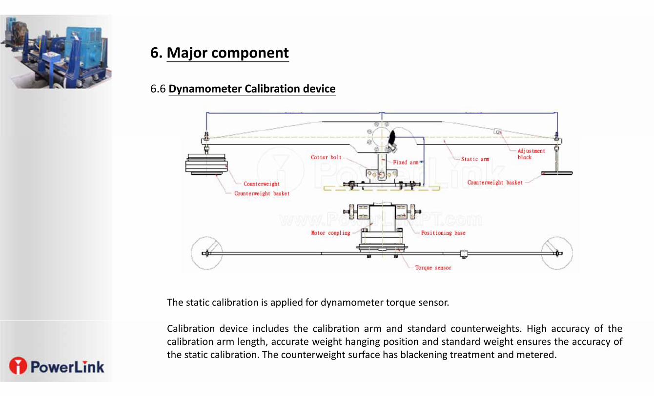
6.6 Dynamometer Calibration device
The static calibration is applied for dynamometer torque sensor.
Calibration device includes the calibration arm and standard counterweights. High accuracy of thecalibration arm length, accurate weight hanging position and standard weight ensures the accuracy ofthe static calibration. The counterweight surface has blackening treatment and metered.
6. Major component
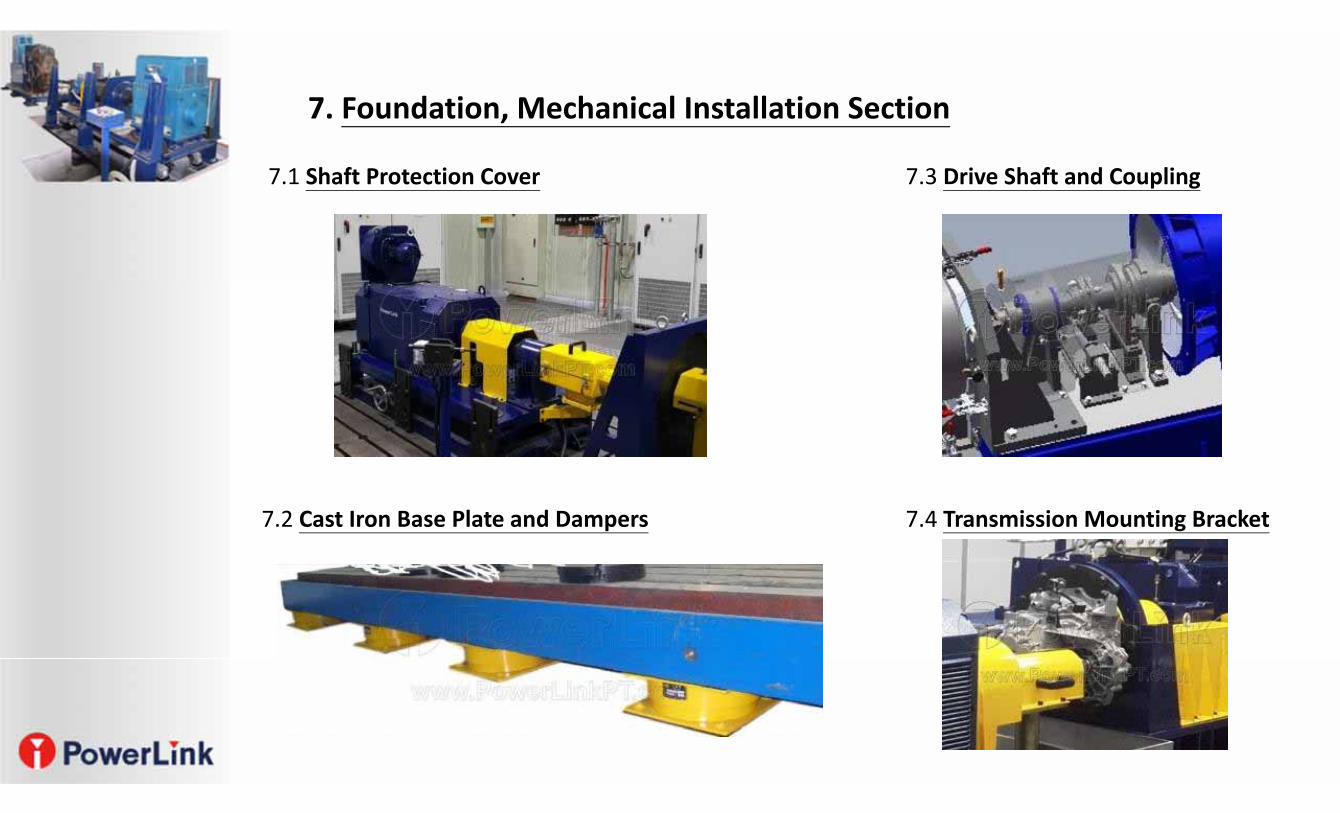
7. Foundation, Mechanical Installation Section
7.1 Shaft Protection Cover 7.3 Drive Shaft and Coupling
7.2 Cast Iron Base Plate and Dampers 7.4 Transmission Mounting Bracket
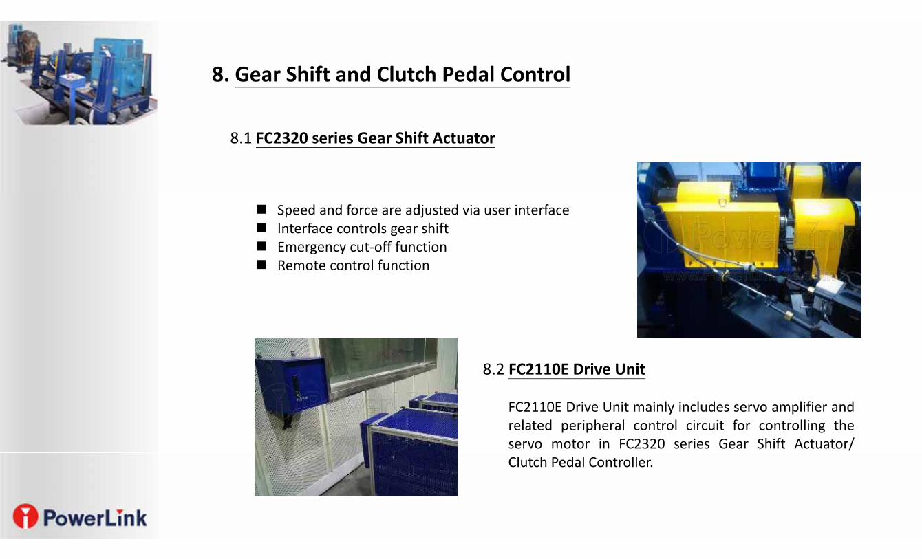
8. Gear Shift and Clutch Pedal Control
8.1 FC2320 series Gear Shift Actuator
Speed and force are adjusted via user interface Interface controls gear shift Emergency cut‐off function Remote control function
8.2 FC2110E Drive Unit
FC2110E Drive Unit mainly includes servo amplifier andrelated peripheral control circuit for controlling theservo motor in FC2320 series Gear Shift Actuator/Clutch Pedal Controller.
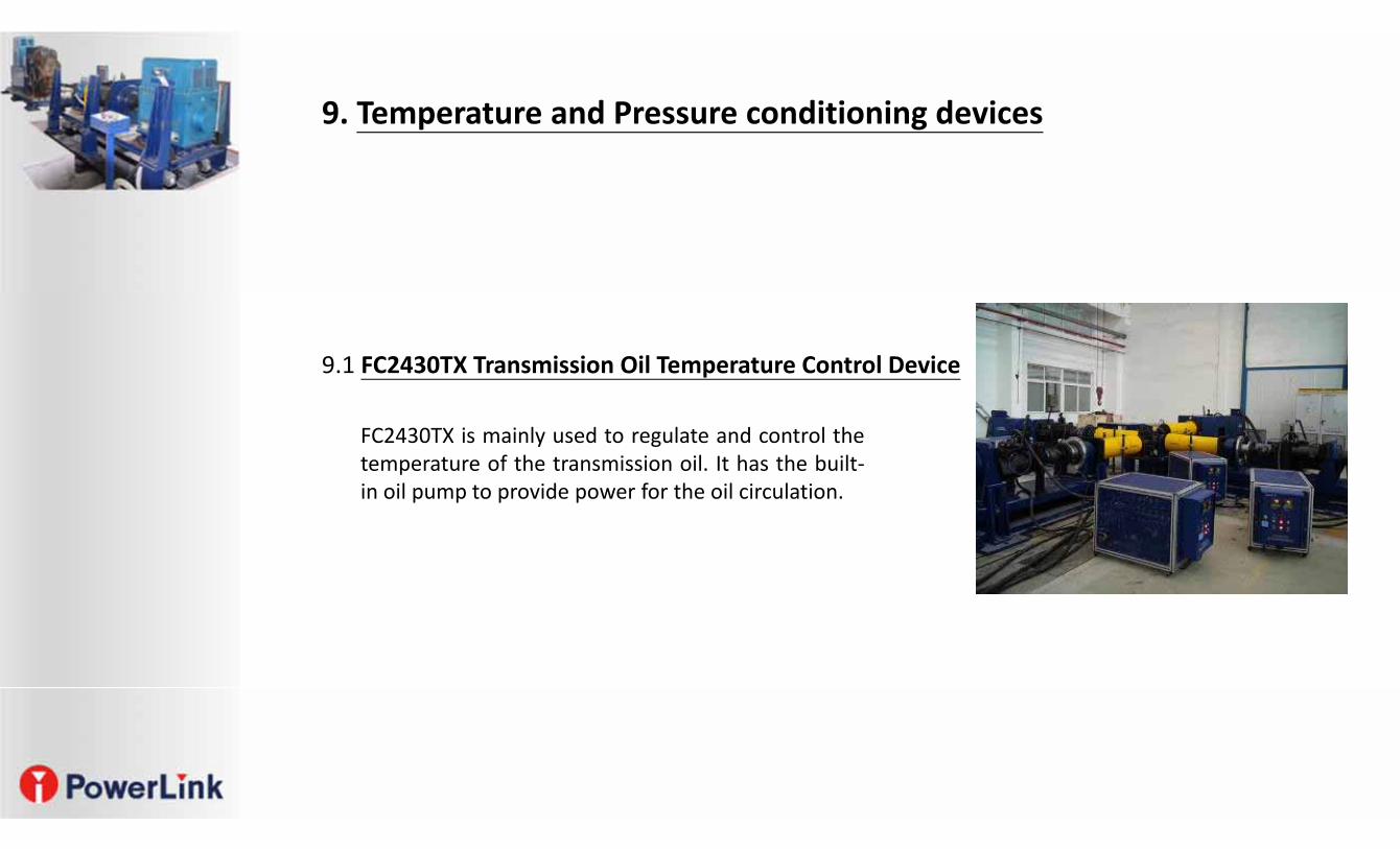
9.1 FC2430TX Transmission Oil Temperature Control Device
FC2430TX is mainly used to regulate and control thetemperature of the transmission oil. It has the built‐in oil pump to provide power for the oil circulation.
9. Temperature and Pressure conditioning devices
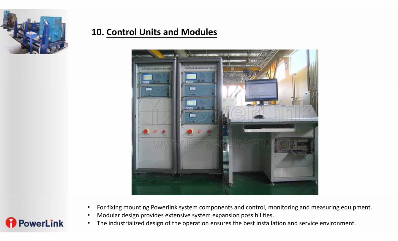
10. Control Units and Modules
• For fixing mounting Powerlink system components and control, monitoring and measuring equipment.• Modular design provides extensive system expansion possibilities.• The industrialized design of the operation ensures the best installation and service environment.
10. Control Units and Modules
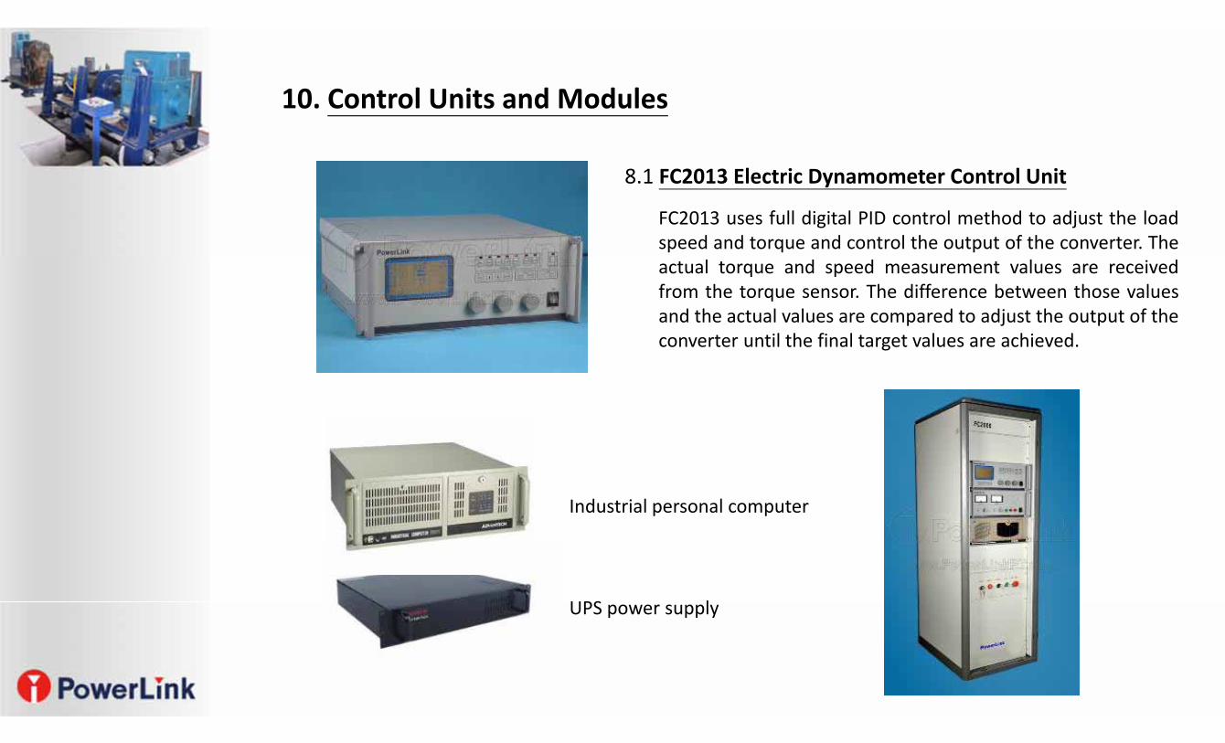
8.1 FC2013 Electric Dynamometer Control Unit
FC2013 uses full digital PID control method to adjust the loadspeed and torque and control the output of the converter. Theactual torque and speed measurement values are receivedfrom the torque sensor. The difference between those valuesand the actual values are compared to adjust the output of theconverter until the final target values are achieved.
Industrial personal computer
UPS power supply
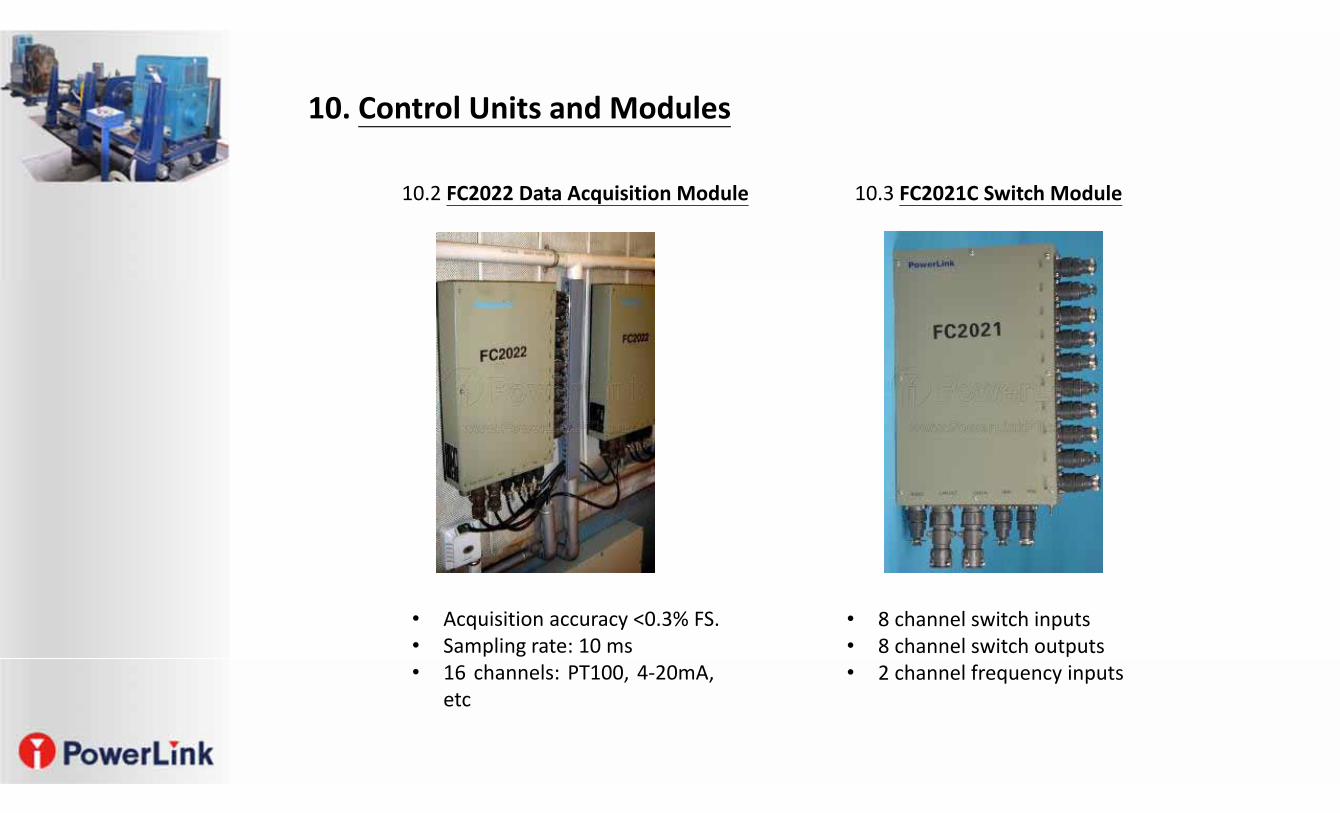
• Acquisition accuracy <0.3% FS.• Sampling rate: 10 ms• 16 channels: PT100, 4‐20mA,
etc
10.2 FC2022 Data Acquisition Module 10.3 FC2021C Switch Module
• 8 channel switch inputs• 8 channel switch outputs• 2 channel frequency inputs
10. Control Units and Modules
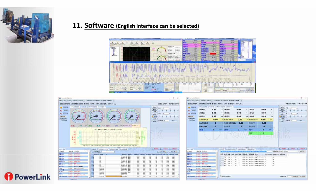
11. Software (English interface can be selected)