Embed Size (px)
Citation preview
PNEG-1156
Design III Series Grain Stir-Ator
Owner’s Manual
PNEG-1156Version: 2.0
Date: 01-08-16

2 PNEG-1156 Design III Series Grain Stir-Ator
Installation Data
Date of Installation: ______________________
Serial Number: _________________________
Bin Size: ______________________________
Auger Length: __________________________
Dealer Name: ___________________________
All information, illustrations, photos and specifications in this manual are based on the latestinformation available at the time of publication. The right is reserved to make changes at anytime without notice.
Table of Contents
PNEG-1156 Design III Series Grain Stir-Ator 3
ContentsChapter 1 Safety .....................................................................................................................................................4
Safety Guidelines .................................................................................................................................. 4Cautionary Symbols Definitions ............................................................................................................ 5Safety Cautions ..................................................................................................................................... 6Safety Sign-Off Sheet ......................................................................................................................... 10
Chapter 2 Safety Decals ......................................................................................................................................11
Chapter 3 Specifications and Dimensions ........................................................................................................12Design III Stir-Ator Overall Dimensions ............................................................................................... 12Design III Stir-Ator Standard Equipment Shipping Weights ................................................................ 14
Chapter 4 Assembly and Installation .................................................................................................................15Final Inspection Check List ................................................................................................................. 15Installation of Design III Stir-Ator ......................................................................................................... 15Track Installation ................................................................................................................................. 16Suspension Chains ............................................................................................................................. 19Switch Box .......................................................................................................................................... 20Frame Rails ......................................................................................................................................... 21Trolley ................................................................................................................................................. 22Yokes .................................................................................................................................................. 25Swing Arm ........................................................................................................................................... 28Junction Box ........................................................................................................................................ 28Trolley Drive Arm to Cable .................................................................................................................. 30Center Suspension System ................................................................................................................. 31Track Gear Motor ................................................................................................................................ 32Leveler Disks ....................................................................................................................................... 32Lifting Stir-Ator .................................................................................................................................... 33Suspension Chain ............................................................................................................................... 36Installing Stir-Ator Augers ................................................................................................................... 39
Chapter 5 Operation ............................................................................................................................................43Start-Up Procedure (Full Bin) .............................................................................................................. 43Track Unit Drive Sprocket ................................................................................................................... 44Stir-Guard Operation (Optional) .......................................................................................................... 44Storage ................................................................................................................................................ 45Drying Guide ....................................................................................................................................... 46
Chapter 6 Parts List .............................................................................................................................................49Design III Stir-Ator Track Unit ............................................................................................................. 50Design III Stir-Ator Switch Boxes and Suspension ............................................................................. 52Design III Stir-Ator Yoke ...................................................................................................................... 54Design III Stir-Ator Double Auger Trolley ............................................................................................ 58Design III Stir-Ator Triple Auger Trolley .............................................................................................. 59Stir-Ator Guard Option - 230V ............................................................................................................. 63
Chapter 7 Service and Maintenance ..................................................................................................................64Cable Tension ..................................................................................................................................... 64Trolley Drive Link ................................................................................................................................ 65Tilt Switch ............................................................................................................................................ 66Safety Shut Off Switch ........................................................................................................................ 67
Chapter 8 Troubleshooting .................................................................................................................................68
Chapter 9 Wiring Diagrams .................................................................................................................................70Design III Stir-Ator Wiring Diagram - 1 Phase - 230V - 60 Hz ............................................................ 70
Chapter 10 Warranty ............................................................................................................................................71

4 PNEG-1156 Design III Series Grain Stir-Ator
1. Safety
Safety Guidelines
Safety guidelines are general-to-specific safety rules that must be followed at all times. This manual is written to help you understand safe operating procedures and problems that can be encountered by the operator and other personnel when using this equipment. Save these safety guidelines for future reference.
As owner or operator, you are responsible for understanding the requirements, hazards, and precautions that exist and to inform others as required. Unqualified persons must stay out of the work area at all times.
Alterations must not be made to the equipment. Alterations can produce dangerous situations resulting in SERIOUS INJURY or DEATH.
This equipment must be installed in accordance with the current installation codes and applicable regulations, which must be carefully followed in all cases. Authorities having jurisdiction must be consulted before installations are made.
When necessary, you must consider the installation location relative to electrical, fuel and water utilities.
Personnel operating or working around equipment must read this manual. This manual must be delivered with equipment to its owner. Failure to read this manual and its safety instructions is a misuse of the equipment.
ST-0001-3

1. Safety
PNEG-1156 Design III Series Grain Stir-Ator 5
Cautionary Symbols Definitions
Cautionary symbols appear in this manual and on product decals. The symbols alert the user of potential safety hazards, prohibited activities and mandatory actions. To help you recognize this information, we use the symbols that are defined below.
DANGER
WARNING
CAUTION
NOTICE
This symbol indicates an imminently hazardous situation which, if not avoided, will result in serious injury or death.
This symbol indicates a potentially hazardous situation which, if not avoided, can result in serious injury or death.
This symbol indicates a potentially hazardous situation which, if not avoided, can result in minor or moderate injury.
This symbol is used to address practices not related to personal injury.
This symbol indicates a general hazard.
This symbol indicates a prohibited activity.
This symbol indicates a mandatory action.
ST-0005-2
1. Safety
6 PNEG-1156 Design III Series Grain Stir-Ator
Safety Cautions
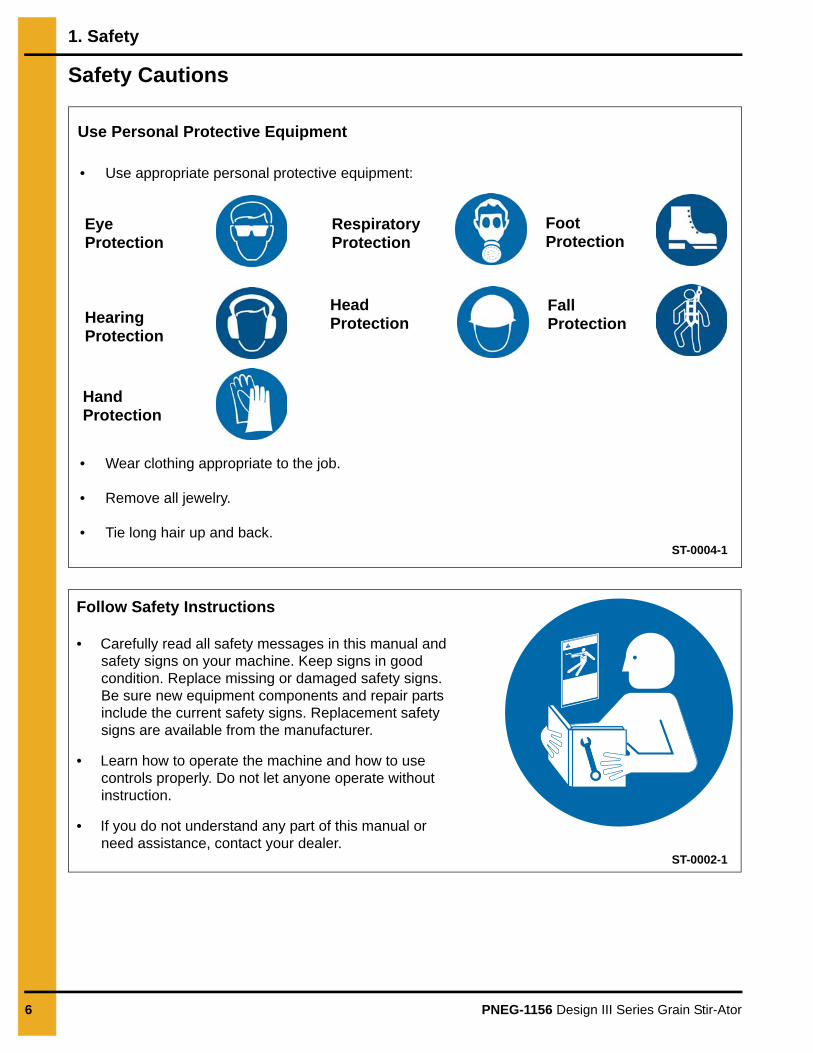
Use Personal Protective Equipment
Eye Protection
Hearing Protection
Hand Protection
Head Protection
Respiratory Protection
Foot Protection
Fall Protection
• Use appropriate personal protective equipment:
• Wear clothing appropriate to the job.
• Remove all jewelry.
• Tie long hair up and back.ST-0004-1
Follow Safety Instructions
• Carefully read all safety messages in this manual and safety signs on your machine. Keep signs in good condition. Replace missing or damaged safety signs. Be sure new equipment components and repair parts include the current safety signs. Replacement safety signs are available from the manufacturer.
• Learn how to operate the machine and how to use controls properly. Do not let anyone operate without instruction.
• If you do not understand any part of this manual or need assistance, contact your dealer.
ST-0002-1
1. Safety
PNEG-1156 Design III Series Grain Stir-Ator 7
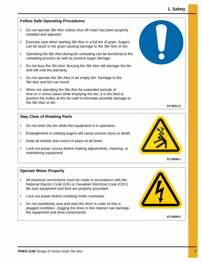
Follow Safe Operating Procedures
• Do not operate Stir-Ator unless shut off chain has been properly installed and adjusted.
• Exercise care when starting Stir-Ator in a full bin of grain. Augers can be stuck in the grain causing damage to the Stir-Ator or bin.
• Operating the Stir-Ator during bin unloading can be beneficial to the unloading process as well as prevent auger damage.
• Do not bury the Stir-Ator. Burying the Stir-Ator will damage the bin and will void the warranty.
• Do not operate the Stir-Ator in an empty bin. Damage to the Stir-Ator and bin can result.
• When not operating the Stir-Ator for extended periods oftime or in some cases while emptying the bin, it is the best to position the trolley at the bin wall to eliminate possible damage to the Stir-Ator or bin.
ST-0011-2
Stay Clear of Rotating Parts
• Do not enter the bin while the equipment is in operation.
• Entanglement in rotating augers will cause serious injury or death.
• Keep all shields and covers in place at all times.
• Lock-out power source before making adjustments, cleaning, or maintaining equipment.
ST-0008-1
Operate Motor Properly
• All electrical connections must be made in accordance with the National Electric Code (US) or Canadian Electrical Code (CEC). Be sure equipment and bins are properly grounded.
• Lock-out power before resetting motor overloads.
• Do not repetitively stop and start the drive in order to free a plugged condition. Jogging the drive in this manner can damage the equipment and drive components.
ST-0009-2
1. Safety
8 PNEG-1156 Design III Series Grain Stir-Ator
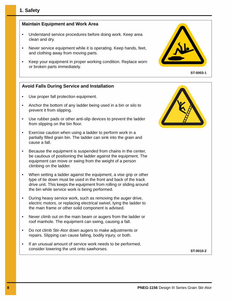
Maintain Equipment and Work Area
• Understand service procedures before doing work. Keep area clean and dry.
• Never service equipment while it is operating. Keep hands, feet, and clothing away from moving parts.
• Keep your equipment in proper working condition. Replace worn or broken parts immediately.
ST-0003-1
Avoid Falls During Service and Installation
• Use proper fall protection equipment.
• Anchor the bottom of any ladder being used in a bin or silo to prevent it from slipping.
• Use rubber pads or other anti-slip devices to prevent the ladder from slipping on the bin floor.
• Exercise caution when using a ladder to perform work in a partially filled grain bin. The ladder can sink into the grain and cause a fall.
• Because the equipment is suspended from chains in the center, be cautious of positioning the ladder against the equipment. The equipment can move or swing from the weight of a person climbing on the ladder.
• When setting a ladder against the equipment, a vise grip or other type of tie down must be used in the front and back of the track drive unit. This keeps the equipment from rolling or sliding around the bin while service work is being performed.
• During heavy service work, such as removing the auger drive, electric motors, or replacing electrical swivel, tying the ladder to the main frame or other solid component is advised.
• Never climb out on the main beam or augers from the ladder or roof manhole. The equipment can swing, causing a fall.
• Do not climb Stir-Ator down augers to make adjustments or repairs. Slipping can cause falling, bodily injury, or both.
• If an unusual amount of service work needs to be performed, consider lowering the unit onto sawhorses. ST-0010-2

1. Safety
PNEG-1156 Design III Series Grain Stir-Ator 9
Use Stir-Ator Equipment Properly
• Exercise care when starting the Stir-Ator in a full bin. Augers can be stuck in the grain which may cause damage to the Stir-Ator or the bin.
• Burying the unit will damage the bin and will void the warranty.
• Do not operate the Stir-Ator in an empty bin. To test the unit in an empty bin, make sure no one is inside the bin, then turn power “on” and “off” immediately. Letting the Stir-Ator run in an empty bin may cause damage to the unit and the bin.
ST-0054-1

1. Safety
10 PNEG-1156 Design III Series Grain Stir-Ator
Safety Sign-Off Sheet
Below is a sign-off sheet that can be used to verify that all personnel have read and understood the safety instructions. This sign-off sheet is provided for your convenience and personal record keeping.
Date Employee Name Supervisor Name
ST-0007

PNEG-1156 Design III Series Grain Stir-Ator 11
2. Safety Decals
The decals shown below must be displayed as shown.
Replacements are available upon request. Write to the following address:
GSI Decals1004 E. Illinois St.Assumption, IL. 62510Phone: 1-217-226-4421
Please note:
1. The decals shown below are not shown in actual size.
2. Keep decals wiped clean at all times.
3. Decals must be replaced if they are destroyed, missing, painted over or can no longer be read.
Location Decal # Decals Description
Both sides of swivelbox and above
junction box cover.DC-1948
Decal, danger high voltage (LG), CE, CSA harmonized.
Top of gearmotor track frame.
DC-1386Decal, chain
warning 2" x 4-1/2"
Both sides of bottom motor mounting rail in trolley and both sides of optional
offset.
1067021 Decal, Warning
On bin door covers(It should be located at any bin entry so it can seen and easily.)
DC-GBC-1ADanger Keep Clear
of Augers
DANGERDANGER DANGERDANGER
DC-1
948
Lockout powerbefore servicing.
Will cause seriousinjury or death.
HIGH VOLTAGE
Couper/verrouiller le courant avant l’entretien.
Causera de sérieuses blessures ou la mort.
HAUTE TENSION
DC-1948GSI Group 217-226-4421
WARNINGSHEAR POINTMoving parts can crushand cut.Keep hands clear ofsprocket and chain.
DC-1386GSI Group Inc. 217-226-4421
AVERTISSEMENTWARNINGROTATING PARTSMay cause serious injury.Keep clear of rotation parts.
PIÈCES EN ROTATIONPeut causer des blessures sérieuses.Restez à l’écart des pièces en rotation!
1067021GSI Group 217-226-4421
Rotating flighting willkill or dismember.
Flowing material willtrap and suffocate.
Crusted material willcollapse and suffocate.
DANGER
Keep clear of all augers.DO NOT ENTER this bin!
If you must enter the bin:1. Shut off and lock out all power.2. Use a safety harness and safety line.3. Station another person outside the bin.4. Avoid the center of the bin.5. Wear proper breathing equipment or respirator.
Failure to heed thesewarnings will result inserious injury or death.
DC-GBC-1AGSI GROUP, INC. 217-226-4421

12 PNEG-1156 Design III Series Grain Stir-Ator
3. Specifications and Dimensions
Design III Stir-Ator Overall Dimensions
Figure 3A
See Chart on Page 13 for Dimensions A, B and C.

3. Specifications and Dimensions
PNEG-1156 Design III Series Grain Stir-Ator 13
Design III Stir-Ator Overall Dimensions (Continued)(See Figure 3A on Page 12.)
**18' and 21' Bin diameter available on DA only.
NOTE: 1. DA frame rails up to 36' are 4'' x 3'' x 1/4''2. DA frame rails 36' are 5'' x 3'' x 5/16''3. TA frame rails are 5'' x 3'' x 5/16''
Figure 3B
Bin Diameter Dimension “A” DA Dimension “A” TADimension “B”
DA and TA Dimension “C”
DA and TA
**18' 40-1/8" NA 114-1/2" 113"
21' 58-1/8" 40-1/8" 132-1/2" 131"
24' 76-1/8" 58-1/8" 150-1/2" 149"
27' 94-1/8" 76-1/8" 168-1/2" 167"
30' 112-1/8" 94-1/8" 186-1/2" 185"
33' 130-1/8" 112-1/8" 204-1/2" 203"
36' 148-1/8" 130-1/8" 222-1/2" 221"
42' NA 166-1/8" 258-1/2" 257"
48' NA 202-1/8" 294-1/2" 293"
Design III Stir-Ator
3. Specifications and Dimensions
14 PNEG-1156 Design III Series Grain Stir-Ator
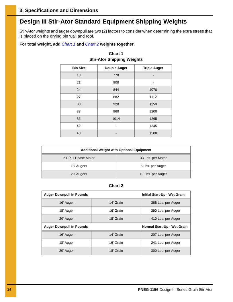
Design III Stir-Ator Standard Equipment Shipping Weights
Stir-Ator weights and auger downpull are two (2) factors to consider when determining the extra stress that is placed on the drying bin wall and roof.
For total weight, add Chart 1 and Chart 2 weights together.
Chart 1Stir-Ator Shipping Weights
Chart 2
Bin Size Double Auger Triple Auger
18' 770 -
21' 808 -
24' 844 1070
27' 882 1112
30' 920 1150
33' 960 1200
36' 1014 1265
42' - 1345
48' - 1500
Additional Weight with Optional Equipment
2 HP, 1 Phase Motor 33 Lbs. per Motor
18' Augers 5 Lbs. per Auger
20' Augers 10 Lbs. per Auger
Auger Downpull in Pounds Initial Start-Up - Wet Grain
16' Auger 14' Grain 368 Lbs. per Auger
18' Auger 16' Grain 390 Lbs. per Auger
20' Auger 18' Grain 410 Lbs. per Auger
Auger Downpull in Pounds Normal Start-Up - Wet Grain
16' Auger 14' Grain 207 Lbs. per Auger
18' Auger 16' Grain 241 Lbs. per Auger
20' Auger 18' Grain 300 Lbs. per Auger

PNEG-1156 Design III Series Grain Stir-Ator 15
4. Assembly and Installation
Final Inspection Check List
1. READ THE STIR-ATOR OWNER’S MANUAL BEFORE INSTALLATION. MANY SERVICE PROBLEMS WILL BE AVOIDED IF THE STIR-ATOR IS PROPERLY INSTALLED.
2. Is there at least 10-1/4" clearance from the center of the track to the lowest part of the roof and roof braces?
3. Are the track splices correctly installed? Consult the diagrams in the owner’s manual.
4. Is the trolley installed correctly with the arm pointing toward the center of the bin?
5. Are the bolt heads holding the yoke end to the frame on the inside on the frame rails and the cotter key spread on the pivot tube?
6. Is the suspension bar properly hung, LEVEL, with the end loops down? Is the 1/2" x 2" bolt holding suspension bar tightly secured? Is the lock nut on tee fitted properly?
7. Is the suspension bar positioned so that the bin “S” hook, to which the shut off chain is attached, is at a right angle to the switch box chain, as shown in Figure 4F on Page 19. THE POWER CORD MUST HAVE MORE SLACK THAN THE SHUT OFF CHAIN or the power cord could be torn out of the switch box if the Design III should malfunction and engage the shut off.
8. Is the frame of the Design III Stir-Ator approximately 1" higher at the center of the bin for each 18' of bin diameter?
9. Are augers 3" (for bins up to 30') or 4" (for bins 33' and larger) off the drying floor at bin wall? (See Figure 4AR on Page 40.)
10. Were the augers deburred with a file? Were the clamp bolts torqued to 140 foot-pounds? Was the roll pin installed correctly?
11. Did you note the instruction NOT to weld flighting at the top end of the auger?
12. Are you sure that the electrician connected the black and red - 1 phase wire to the disconnect box and the green wire to the ground? (See Wiring Diagram on Page 70.) BE SURE BIN IS GROUNDED.
13. Are you keeping a record of the serial number for each owner?
14. Did you make sure that the owner received and signed for his OWNER’S MANUAL and was instructed that reading and understanding the manual are essential for proper and efficient operation of the Stir-Ator?
15. Did you install the safety decals on the inside and outside of the walk-in door and the manhole cover?
Installation of Design III Stir-Ator
NOTE: Prior to assembly and installation, consult the bin erection manual or manufacturer for any special unit hanging or support locations.
1. Before assembling the bin, place the Design III Stir-Ator (without the augers) in the center of the bin floor. The top ring of the bin is then assembled in the usual way.

4. Assembly and Installation
16 PNEG-1156 Design III Series Grain Stir-Ator
Track Installation
NOTE: The wall track has two (2) different hole spacings: 18-15/16" on the double auger units and 12-5/8" on the triple auger units. (See Figure 4A.)
Figure 4A
1. The track is installed 10-1/4" distance from the eave of the bin to the center line of the track. Bins with steeply pitched or domed roofs may allow the 10-1/4" distance to be reduced; roofs with low or flat profiles may require more clearance. Reinforcements to the roof or roof ladder which might interfere with the movement of the Stir-Ator should be trimmed. (See Figure 4B.) If this cannot be done, the 10-1/4" distance from the eave to the track bolt center line must be increased proportionately.
Figure 4B
Design III Stir-Ator
4. Assembly and Installation
PNEG-1156 Design III Series Grain Stir-Ator 17
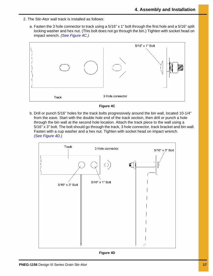
2. The Stir-Ator wall track is installed as follows:
a. Fasten the 3 hole connector to track using a 5/16" x 1" bolt through the first hole and a 5/16" split locking washer and hex nut. (This bolt does not go through the bin.) Tighten with socket head on impact wrench. (See Figure 4C.)
Figure 4C
b. Drill or punch 5/16" holes for the track bolts progressively around the bin wall, located 10-1/4" from the eave. Start with the double hole end of the track section, then drill or punch a hole through the bin wall at the second hole location. Attach the track piece to the wall using a 5/16" x 3" bolt. The bolt should go through the track, 3 hole connector, track bracket and bin wall. Fasten with a cup washer and a hex nut. Tighten with socket head on impact wrench. (See Figure 4D.)
Figure 4D
4. Assembly and Installation
18 PNEG-1156 Design III Series Grain Stir-Ator
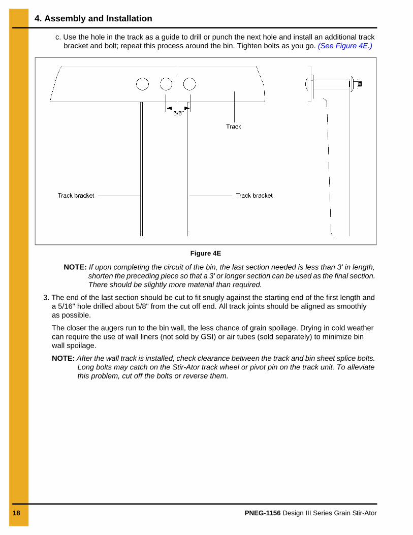
c. Use the hole in the track as a guide to drill or punch the next hole and install an additional track bracket and bolt; repeat this process around the bin. Tighten bolts as you go. (See Figure 4E.)
Figure 4E
NOTE: If upon completing the circuit of the bin, the last section needed is less than 3' in length, shorten the preceding piece so that a 3' or longer section can be used as the final section. There should be slightly more material than required.
3. The end of the last section should be cut to fit snugly against the starting end of the first length and a 5/16" hole drilled about 5/8" from the cut off end. All track joints should be aligned as smoothly as possible.
The closer the augers run to the bin wall, the less chance of grain spoilage. Drying in cold weather can require the use of wall liners (not sold by GSI) or air tubes (sold separately) to minimize bin wall spoilage.
NOTE: After the wall track is installed, check clearance between the track and bin sheet splice bolts. Long bolts may catch on the Stir-Ator track wheel or pivot pin on the track unit. To alleviate this problem, cut off the bolts or reverse them.

4. Assembly and Installation
PNEG-1156 Design III Series Grain Stir-Ator 19
Suspension Chains
1. The bin roof is then assembled and the suspension chains are dropped through the fill-hole. Two (2) chains are used on the double auger units and three (3) chains are used on the triple auger units. Space the suspension hooks equally apart around the center fill-hole collar, placing them in reference to the manhole where the shut off switch box is to be located. Place chains through the hole and then slide the chain down into the slot. (See Figure 4F and Figure 4G.) A hole in the suspension hooks is provided if bolting the hooks in position is desired. NOTE: For GSI bins larger than 33' diameter an alternate method of mounting is to attach suspension chain to intermediate center collar. (See Figure 4H on Page 20.)
Figure 4F Viewed from Top of Bin
Figure 4G
Do not use the bolt in the suspension hook to support the entire unit. The outside end of the Stir-Ator should be supported by the track.

4. Assembly and Installation
20 PNEG-1156 Design III Series Grain Stir-Ator
Figure 4H
Switch Box1. Remove bags of hardware from the switch box. Install safety switch shut off, switch box and box
brace to bin roof above the manhole opening. See Figure 4I for recommended mounting height and then drill the hole in the roof.
NOTE: Do not mount too low. Place as far up on roof sheet as possible. While still being able toreach handle.
2. Mount the switch box using the hardware provided with disconnect box, refer to Design III Stir-Ator switch boxes and suspension parts list on Page 52.
3. Fasten shut off support chain(s) to bin roof using existing roof bolts and a 5/16" flat washer and hex nut. Three (3) support chains should be equally spaced between the switch box and the center of the bin.
Figure 4I
Design III Stir-Ator
Mounting the box lower than the minimum recommended height could cause the box to be caught by the Stir-Ator as it moves around the bin, causing possible damage or serious electrical shock.
4. Assembly and Installation
PNEG-1156 Design III Series Grain Stir-Ator 21
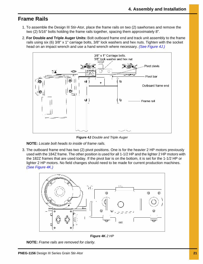
Frame Rails
1. To assemble the Design III Stir-Ator, place the frame rails on two (2) sawhorses and remove the two (2) 5/16" bolts holding the frame rails together, spacing them approximately 8".
2. For Double and Triple Auger Units: Bolt outboard frame end and track unit assembly to the frame rails using six (6) 3/8" x 1" carriage bolts, 3/8" lock washers and hex nuts. Tighten with the socket head on an impact wrench and use a hand wrench where necessary. (See Figure 4J.)
Figure 4J Double and Triple Auger
NOTE: Locate bolt heads to inside of frame rails.
3. The outboard frame end has two (2) pivot positions. One is for the heavier 2 HP motors previously used with the 184Z frame. The other position is used for all 1-1/2 HP and the lighter 2 HP motors with the 182Z frames that are used today. If the pivot bar is on the bottom, it is set for the 1-1/2 HP or lighter 2 HP motors. No field changes should need to be made for current production machines.(See Figure 4K.)
Figure 4K 2 HP
NOTE: Frame rails are removed for clarity.
4. Assembly and Installation
22 PNEG-1156 Design III Series Grain Stir-Ator
Trolley
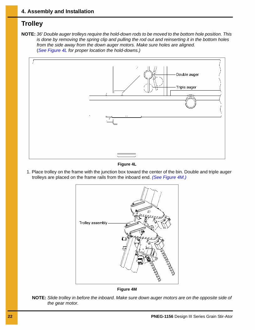
NOTE: 36' Double auger trolleys require the hold-down rods to be moved to the bottom hole position. This is done by removing the spring clip and pulling the rod out and reinserting it in the bottom holes from the side away from the down auger motors. Make sure holes are aligned. (See Figure 4L for proper location the hold-downs.)
Figure 4L
1. Place trolley on the frame with the junction box toward the center of the bin. Double and triple auger trolleys are placed on the frame rails from the inboard end. (See Figure 4M.)
Figure 4M
NOTE: Slide trolley in before the inboard. Make sure down auger motors are on the opposite side of the gear motor.
4. Assembly and Installation
PNEG-1156 Design III Series Grain Stir-Ator 23
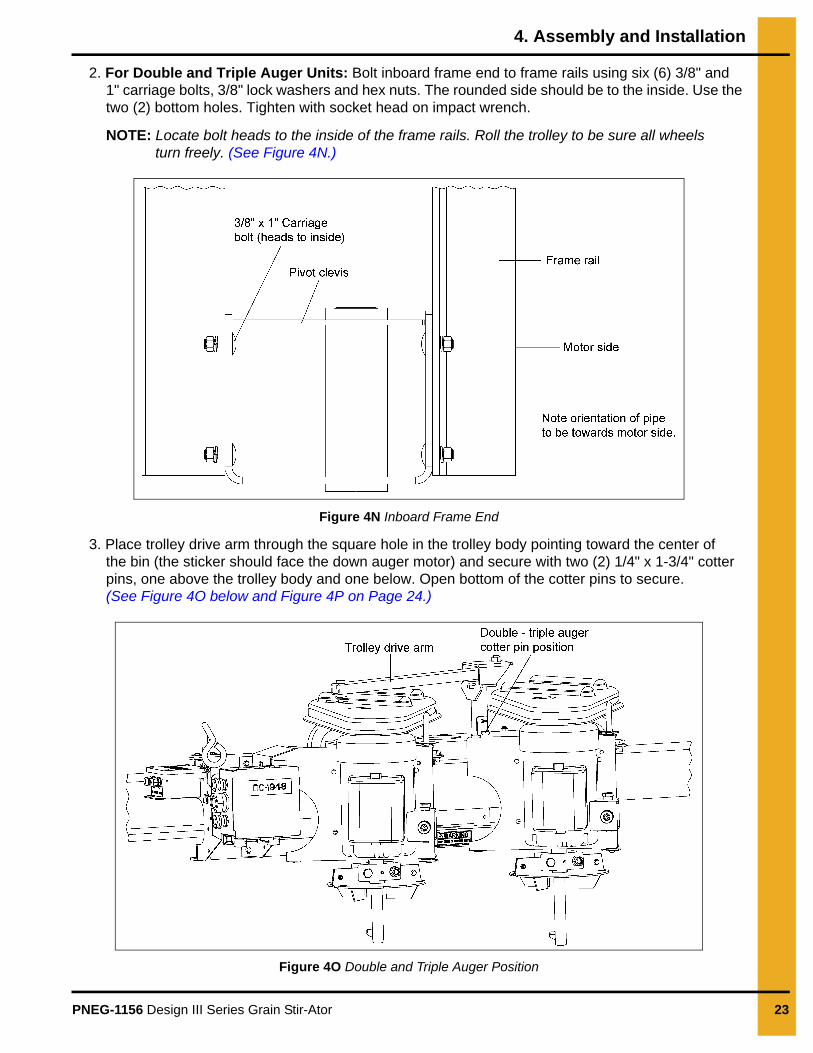
2. For Double and Triple Auger Units: Bolt inboard frame end to frame rails using six (6) 3/8" and 1" carriage bolts, 3/8" lock washers and hex nuts. The rounded side should be to the inside. Use the two (2) bottom holes. Tighten with socket head on impact wrench.
NOTE: Locate bolt heads to the inside of the frame rails. Roll the trolley to be sure all wheels turn freely. (See Figure 4N.)
Figure 4N Inboard Frame End
3. Place trolley drive arm through the square hole in the trolley body pointing toward the center of the bin (the sticker should face the down auger motor) and secure with two (2) 1/4" x 1-3/4" cotter pins, one above the trolley body and one below. Open bottom of the cotter pins to secure.(See Figure 4O below and Figure 4P on Page 24.)
Figure 4O Double and Triple Auger Position
4. Assembly and Installation
24 PNEG-1156 Design III Series Grain Stir-Ator
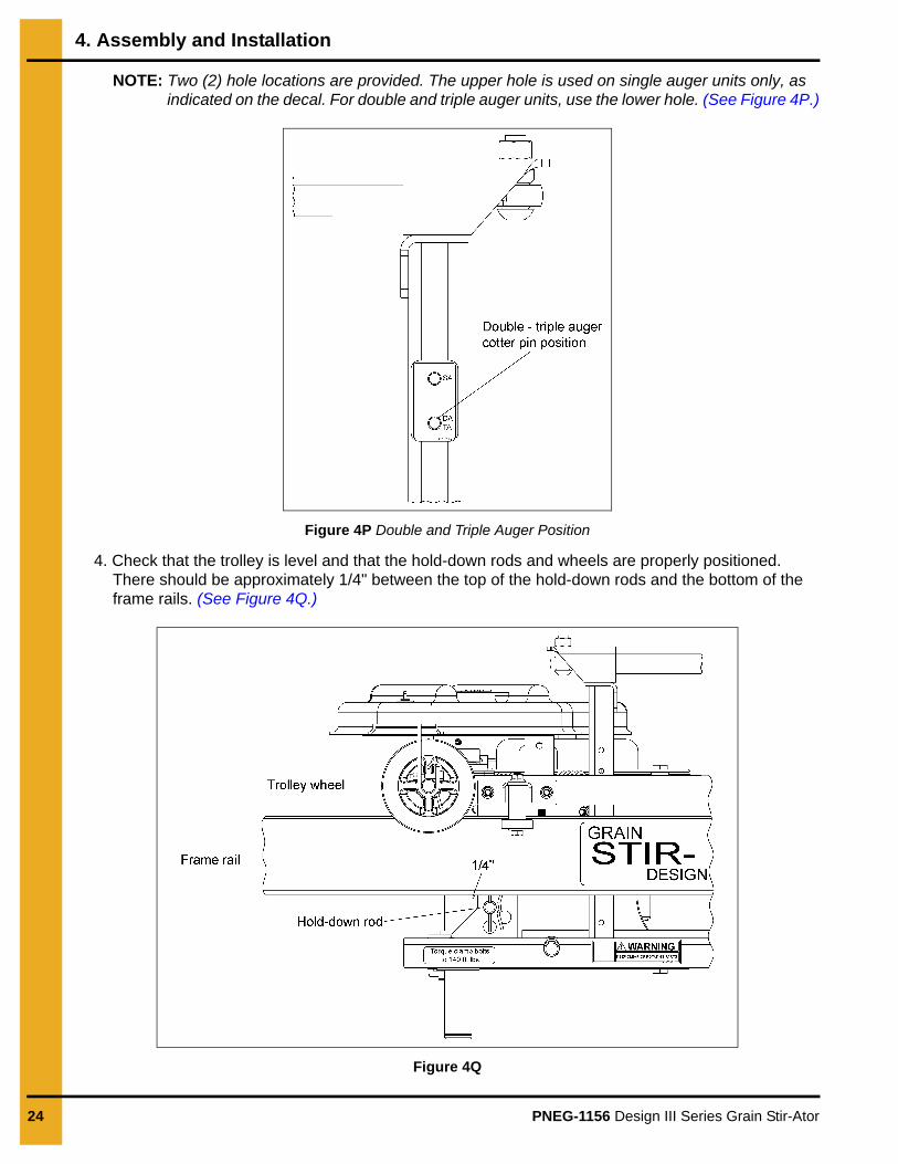
NOTE: Two (2) hole locations are provided. The upper hole is used on single auger units only, as indicated on the decal. For double and triple auger units, use the lower hole. (See Figure 4P.)
Figure 4P Double and Triple Auger Position
4. Check that the trolley is level and that the hold-down rods and wheels are properly positioned. There should be approximately 1/4" between the top of the hold-down rods and the bottom of the frame rails. (See Figure 4Q.)
Figure 4Q
4. Assembly and Installation
PNEG-1156 Design III Series Grain Stir-Ator 25
Yokes
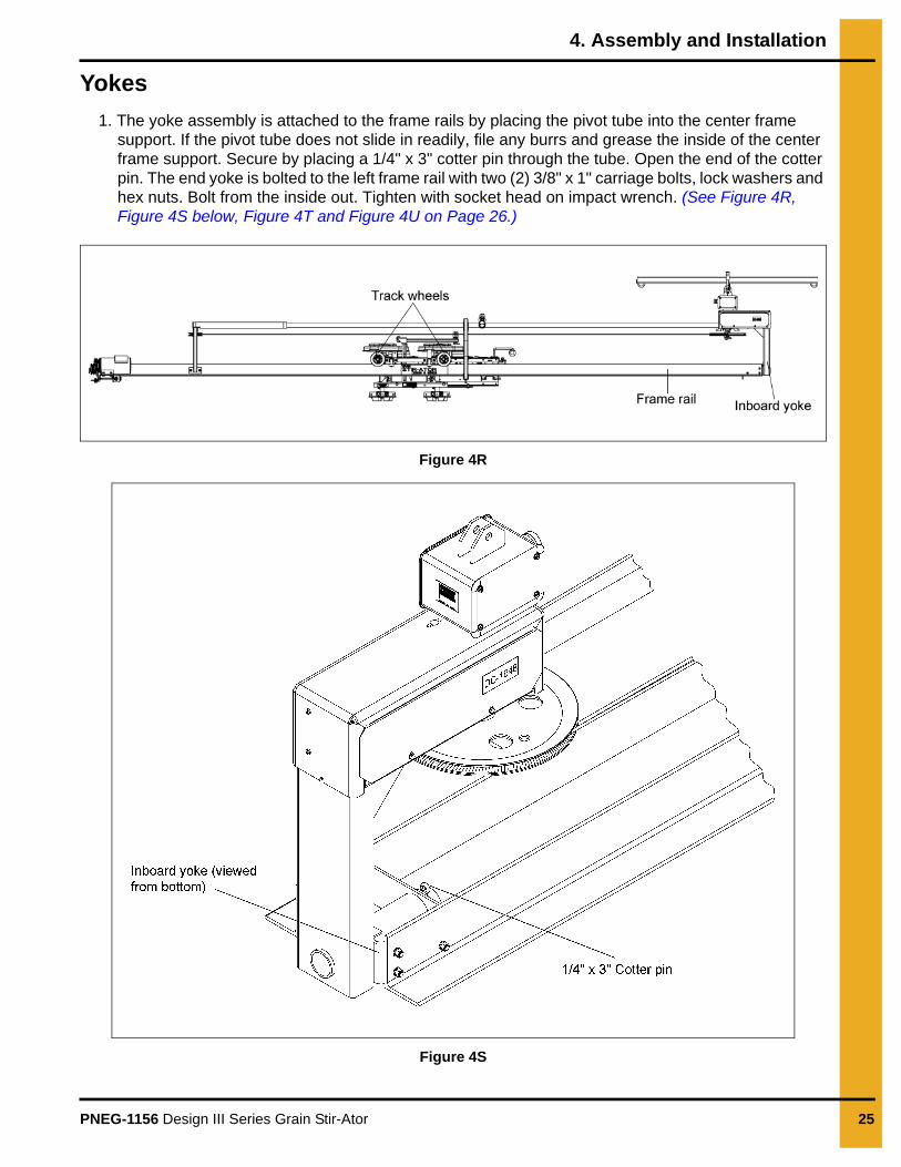
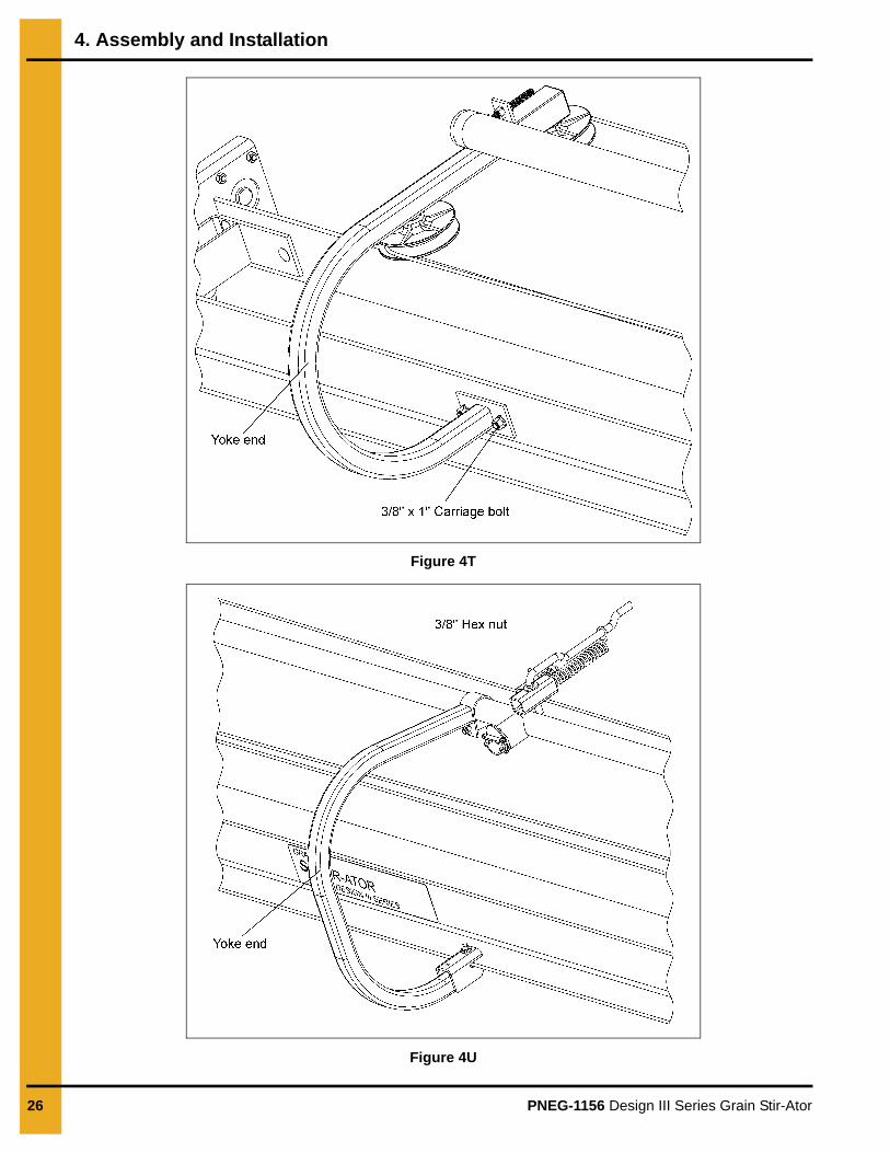
1. The yoke assembly is attached to the frame rails by placing the pivot tube into the center frame support. If the pivot tube does not slide in readily, file any burrs and grease the inside of the center frame support. Secure by placing a 1/4" x 3" cotter pin through the tube. Open the end of the cotter pin. The end yoke is bolted to the left frame rail with two (2) 3/8" x 1" carriage bolts, lock washers and hex nuts. Bolt from the inside out. Tighten with socket head on impact wrench. (See Figure 4R, Figure 4S below, Figure 4T and Figure 4U on Page 26.)
Figure 4R
Figure 4S
4. Assembly and Installation
26 PNEG-1156 Design III Series Grain Stir-Ator
Figure 4T
Figure 4U
4. Assembly and Installation
PNEG-1156 Design III Series Grain Stir-Ator 27
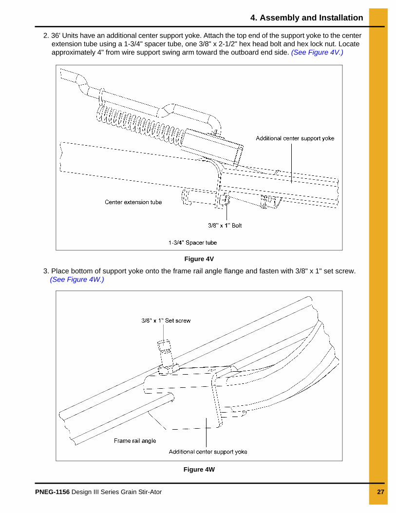
2. 36' Units have an additional center support yoke. Attach the top end of the support yoke to the center extension tube using a 1-3/4" spacer tube, one 3/8" x 2-1/2" hex head bolt and hex lock nut. Locate approximately 4" from wire support swing arm toward the outboard end side. (See Figure 4V.)
Figure 4V
3. Place bottom of support yoke onto the frame rail angle flange and fasten with 3/8" x 1" set screw. (See Figure 4W.)
Figure 4W

4. Assembly and Installation
28 PNEG-1156 Design III Series Grain Stir-Ator
Swing Arm
1. Carefully remove the zip tie that are holding cord to swing arm.
Junction Box
1. Bolt trolley wire support rod to the top of the angle support with two (2) 1/4" x 5/8" flange bolt and 1/4" hex flanged lock nuts. After removing the screw from the junction box cover, feed electrical wires through the end loop of the wire support and into the junction box. Connect ends to terminal wires through the end loop of the wire support and into the junction box. Connect ends to the terminal strip and the solid state electronic tilt switch electrical wire using wire connectors. (See Wiring Diagram on Page 70 or See Figure 4X.)
Figure 4X
Swing arm is spring loaded. Extreme care must be exercised when cutting the shipping zip ties loose to avoid possibility of personal or bodily injury, as arm will snap back when freed.CAUTION
4. Assembly and Installation
PNEG-1156 Design III Series Grain Stir-Ator 29
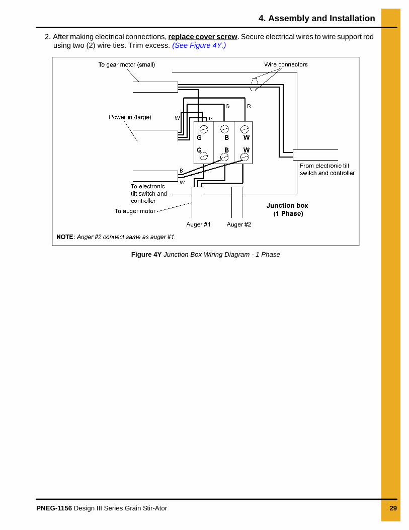
2. After making electrical connections, replace cover screw. Secure electrical wires to wire support rod using two (2) wire ties. Trim excess. (See Figure 4Y.)
Figure 4Y Junction Box Wiring Diagram - 1 Phase
4. Assembly and Installation
30 PNEG-1156 Design III Series Grain Stir-Ator
Trolley Drive Arm to Cable
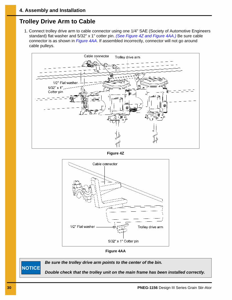
1. Connect trolley drive arm to cable connector using one 1/4" SAE (Society of Automotive Engineers standard) flat washer and 5/32" x 1" cotter pin. (See Figure 4Z and Figure 4AA.) Be sure cable connector is as shown in Figure 4AA. If assembled incorrectly, connector will not go around cable pulleys.
Figure 4Z
Figure 4AA
Be sure the trolley drive arm points to the center of the bin.
Double check that the trolley unit on the main frame has been installed correctly.NOTICE

4. Assembly and Installation
PNEG-1156 Design III Series Grain Stir-Ator 31
Center Suspension System
1. The Center Suspension System: Double auger units use a single piece square tube. The triple auger units use a two (2) piece square tube “T” assembly.
2. For Double Auger Units: Place the attachment link on the single suspension tube into the welded clevis provided on the yoke head. Fasten with one 1/2" x 2" hex head bolt and hex lock nut. Tighten with ratcheting hand wrench. (See Figure 4AB.)
Figure 4AB Double Auger
3. For Triple Auger Units: First assemble two (2) piece “T” square tube sections using one 1/2" x 2" hex head bolt and hex lock nut. Tighten with ratcheting hand wrench. (See Figure 4AC.)
Figure 4AC Triple Auger
NOTE: Be sure small loops on the suspension tube ends are always down.
4. Assembly and Installation
32 PNEG-1156 Design III Series Grain Stir-Ator
Track Gear Motor
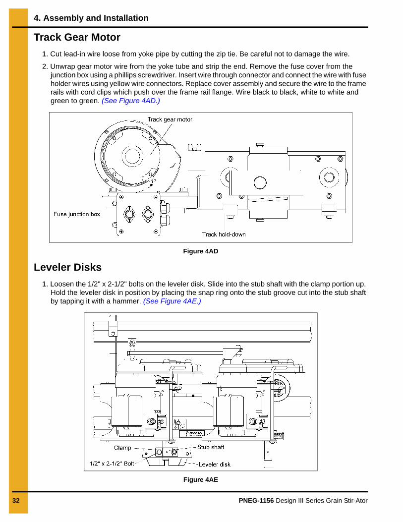
1. Cut lead-in wire loose from yoke pipe by cutting the zip tie. Be careful not to damage the wire.
2. Unwrap gear motor wire from the yoke tube and strip the end. Remove the fuse cover from the junction box using a phillips screwdriver. Insert wire through connector and connect the wire with fuse holder wires using yellow wire connectors. Replace cover assembly and secure the wire to the frame rails with cord clips which push over the frame rail flange. Wire black to black, white to white and green to green. (See Figure 4AD.)
Figure 4AD
Leveler Disks
1. Loosen the 1/2" x 2-1/2" bolts on the leveler disk. Slide into the stub shaft with the clamp portion up. Hold the leveler disk in position by placing the snap ring onto the stub groove cut into the stub shaft by tapping it with a hammer. (See Figure 4AE.)
Figure 4AE
4. Assembly and Installation
PNEG-1156 Design III Series Grain Stir-Ator 33
Lifting Stir-Ator
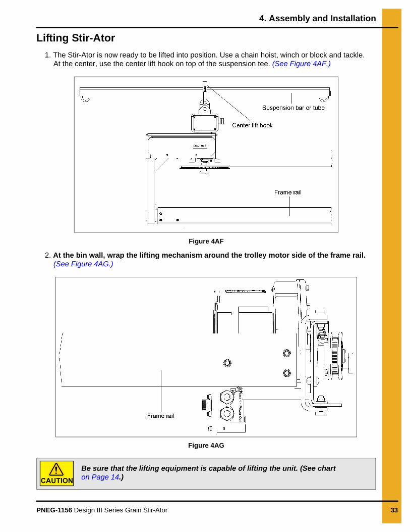
1. The Stir-Ator is now ready to be lifted into position. Use a chain hoist, winch or block and tackle. At the center, use the center lift hook on top of the suspension tee. (See Figure 4AF.)
Figure 4AF
2. At the bin wall, wrap the lifting mechanism around the trolley motor side of the frame rail. (See Figure 4AG.)
Figure 4AG
Be sure that the lifting equipment is capable of lifting the unit. (See chart on Page 14.)CAUTION
4. Assembly and Installation
34 PNEG-1156 Design III Series Grain Stir-Ator
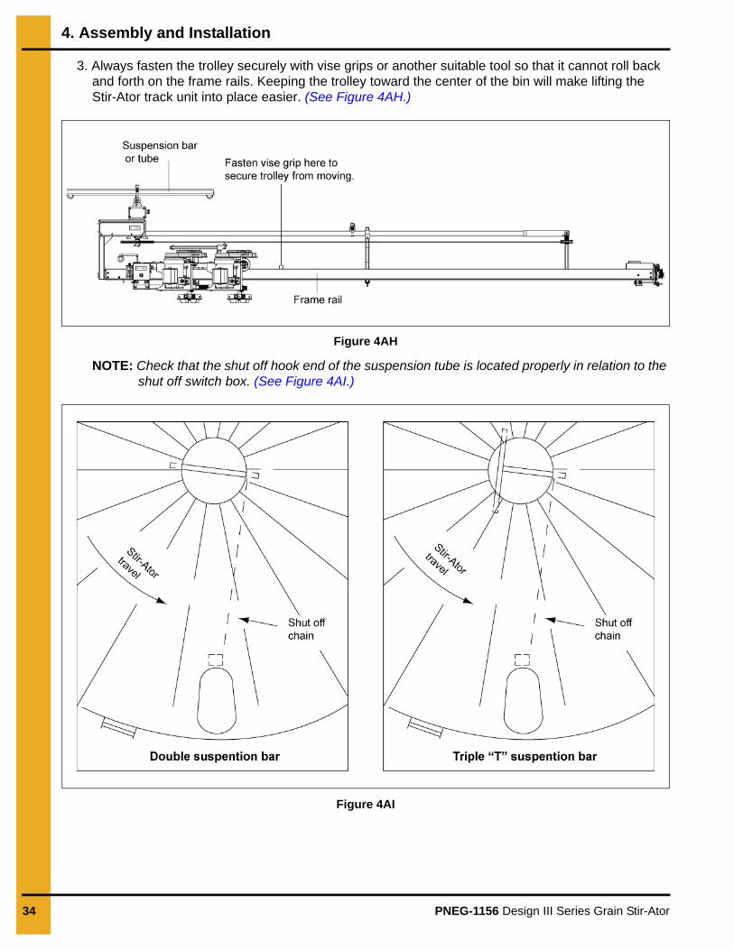
3. Always fasten the trolley securely with vise grips or another suitable tool so that it cannot roll back and forth on the frame rails. Keeping the trolley toward the center of the bin will make lifting the Stir-Ator track unit into place easier. (See Figure 4AH.)
Figure 4AH
NOTE: Check that the shut off hook end of the suspension tube is located properly in relation to the shut off switch box. (See Figure 4AI.)
Figure 4AI
4. Assembly and Installation
PNEG-1156 Design III Series Grain Stir-Ator 35
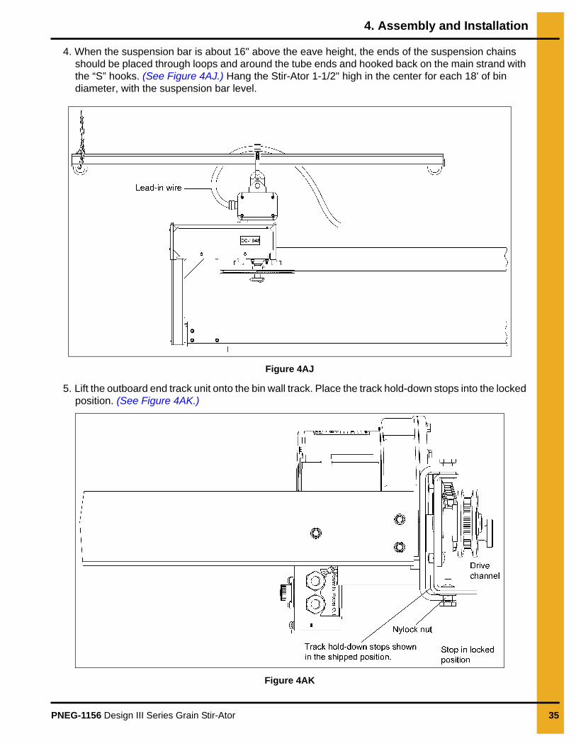
4. When the suspension bar is about 16" above the eave height, the ends of the suspension chains should be placed through loops and around the tube ends and hooked back on the main strand with the “S” hooks. (See Figure 4AJ.) Hang the Stir-Ator 1-1/2" high in the center for each 18' of bin diameter, with the suspension bar level.
Figure 4AJ
5. Lift the outboard end track unit onto the bin wall track. Place the track hold-down stops into the locked position. (See Figure 4AK.)
Figure 4AK

4. Assembly and Installation
36 PNEG-1156 Design III Series Grain Stir-Ator
6. The unit should be hung slightly higher at the center than at the bin wall. Stand at a right angle to the frame rails and sight along them and across to the wall track. When the center height is properly positioned, the frame should be 1" higher at the center on an 18' diameter bin; 1-1/2" higher on a 27' diameter bin; and 2" higher on a 36' diameter bin. Be sure the suspension tube is always positioned level so it will not be hit by any part of the Stir-Ator as it rotates around the bin. (See Figure 4AL.)
Figure 4AL View from Under Side
Suspension Chain
1. Check to be sure the shut off hook end of the suspension tube is located 90° to the switch box. If not, reposition the suspension chain hooks around the center fill hole.
2. Attach the link end of the shut off chain to the “S” hook on the switch box handle. Re-hook the excess chain with an “S” hook attached to the shut off chain so that it will not get caught on the unit. (See Figure 4AM.)
Figure 4AM
Lock the track unit in place on the wall with vise grips, clamps or another means so the unit will not skid.CAUTION

4. Assembly and Installation
PNEG-1156 Design III Series Grain Stir-Ator 37
3. Use the shut off support chain(s) to hold the shut off chain so that there is adequate clearance between the shut off chain and the Stir-Ator as it travels underneath. (See Figure 4AN.)
Figure 4AN
4. Remove the wire support “S” hook which is banded to the hook attached to the chain end with a plastic tie strap. Loop the support chain under the shut off chain lifting it for clearance and hook it to the main strand. (See Figure 4AO.)
Figure 4AO
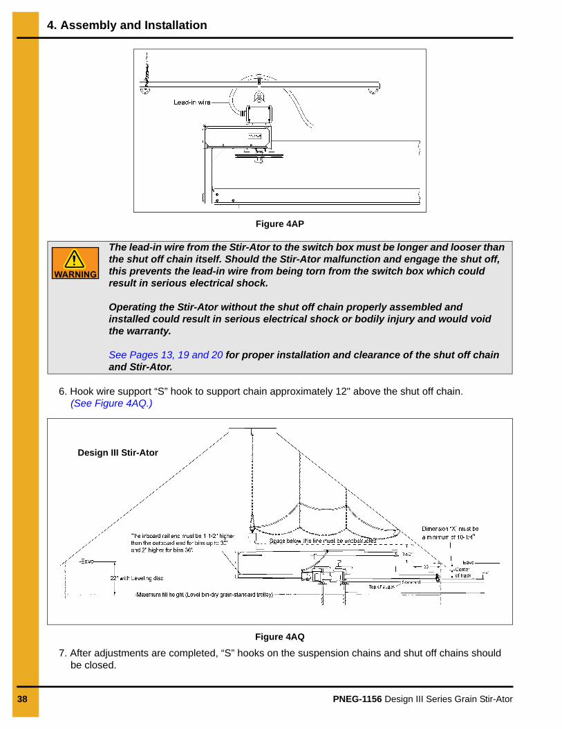
5. String the lead-in wire through the chain link clevis on the bottom of the suspension bar toward the bar with the safety chain “S” hook. (Do not attach the wire to the end of the suspension bar.) The lead-in wire can then be suspended above the safety chain and routed to the switch box. (See Figure 4AP on Page 38.)
Design III Stir-Ator
Switch box
Chain hooks
4. Assembly and Installation
38 PNEG-1156 Design III Series Grain Stir-Ator
Figure 4AP
6. Hook wire support “S” hook to support chain approximately 12" above the shut off chain. (See Figure 4AQ.)
Figure 4AQ
7. After adjustments are completed, “S” hooks on the suspension chains and shut off chains should be closed.
The lead-in wire from the Stir-Ator to the switch box must be longer and looser than the shut off chain itself. Should the Stir-Ator malfunction and engage the shut off, this prevents the lead-in wire from being torn from the switch box which could result in serious electrical shock.
Operating the Stir-Ator without the shut off chain properly assembled and installed could result in serious electrical shock or bodily injury and would void the warranty.
See Pages 13, 19 and 20 for proper installation and clearance of the shut off chain and Stir-Ator.
Design III Stir-Ator

4. Assembly and Installation
PNEG-1156 Design III Series Grain Stir-Ator 39
Check Movement
Move trolley from the extreme outboard end of the main frame to the inboard end and back again to be sure there is no trolley interference and that there is sufficient electric cord allowed from the support swing arm to reach both ends.
Power
A professional electrician must be employed to bring the power line to the Stir-Ator. The bin must be grounded and all the wiring must be done in accordance with local and national codes to avoid bodily injury and even death.
Installing Stir-Ator Augers
Determine the Required Length of the Auger
Install Stir-Ator augers by standing them up against the trolley to measure length. When measuring the auger length, be sure the trolley is close to the bin wall. If the unit has been correctly installed the measurement between the drying floor and the Stir-Ator will be the shortest at the wall.
The Stir-Ator augers should clear the drying floor by 3" for bins up to 30' and 4" for bins 33' and over. If a grain flow system is installed, the augers should clear the drying floor by 30". If a bin sweep is to be installed, then the clearance should match that for the floor by 3" for bins up to 30' and 4" for bins 33' and over.
4. Assembly and Installation
40 PNEG-1156 Design III Series Grain Stir-Ator
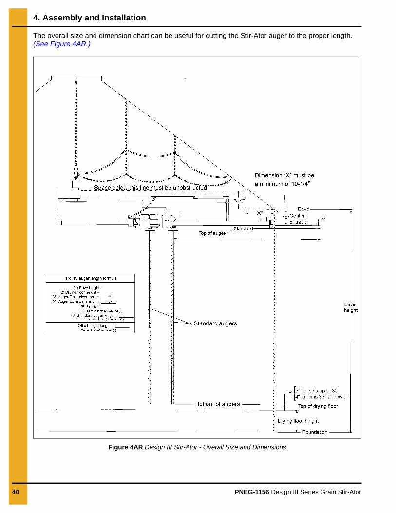
The overall size and dimension chart can be useful for cutting the Stir-Ator auger to the proper length. (See Figure 4AR.)
Figure 4AR Design III Stir-Ator - Overall Size and Dimensions
4. Assembly and Installation
PNEG-1156 Design III Series Grain Stir-Ator 41
Cutting Augers
NOTE: When shortening a down auger, cut from the bottom and be sure the flighting is re-welded properly before cutting the auger. Cutting the auger from the top will void the warranty.
1. Stir-Ator down augers are manufactured to allow them to be cut to the required length by cutting them from the bottom end instead of the top. All augers have flighting to within 8" from the top and hard-surfaced augers will have all but the top pitch of flighting hard-surfaced.
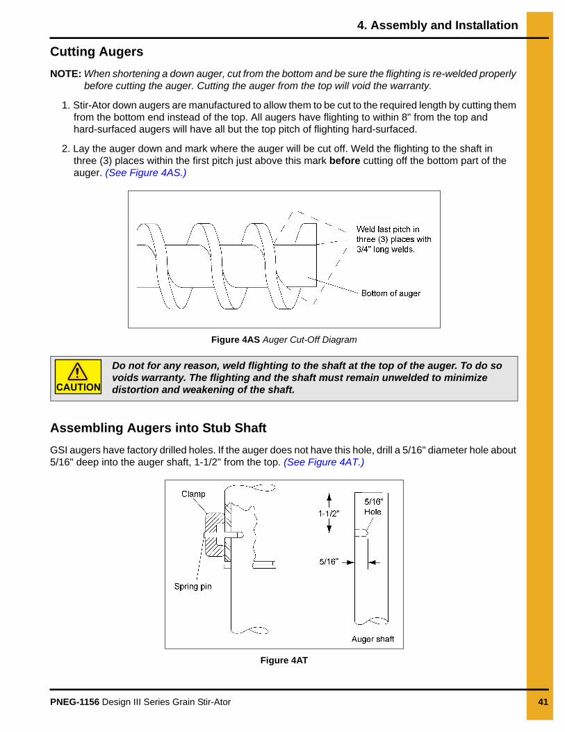
2. Lay the auger down and mark where the auger will be cut off. Weld the flighting to the shaft in three (3) places within the first pitch just above this mark before cutting off the bottom part of the auger. (See Figure 4AS.)
Figure 4AS Auger Cut-Off Diagram
Assembling Augers into Stub Shaft
GSI augers have factory drilled holes. If the auger does not have this hole, drill a 5/16" diameter hole about 5/16" deep into the auger shaft, 1-1/2" from the top. (See Figure 4AT.)
Figure 4AT
Do not for any reason, weld flighting to the shaft at the top of the auger. To do so voids warranty. The flighting and the shaft must remain unwelded to minimize distortion and weakening of the shaft.CAUTION
4. Assembly and Installation
42 PNEG-1156 Design III Series Grain Stir-Ator
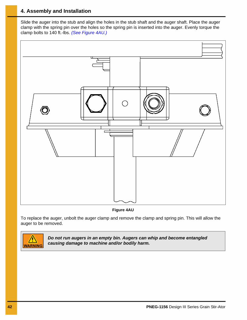
Slide the auger into the stub and align the holes in the stub shaft and the auger shaft. Place the auger clamp with the spring pin over the holes so the spring pin is inserted into the auger. Evenly torque the clamp bolts to 140 ft.-lbs. (See Figure 4AU.)
Figure 4AU
To replace the auger, unbolt the auger clamp and remove the clamp and spring pin. This will allow the auger to be removed.
Do not run augers in an empty bin. Augers can whip and become entangled causing damage to machine and/or bodily harm.
PNEG-1156 Design III Series Grain Stir-Ator 43
5. Operation
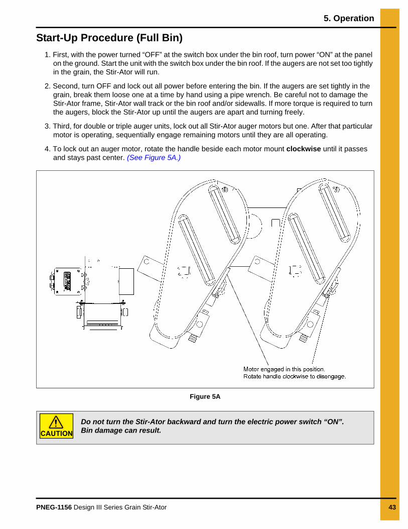
Start-Up Procedure (Full Bin)
1. First, with the power turned “OFF” at the switch box under the bin roof, turn power “ON” at the panel on the ground. Start the unit with the switch box under the bin roof. If the augers are not set too tightly in the grain, the Stir-Ator will run.
2. Second, turn OFF and lock out all power before entering the bin. If the augers are set tightly in the grain, break them loose one at a time by hand using a pipe wrench. Be careful not to damage the Stir-Ator frame, Stir-Ator wall track or the bin roof and/or sidewalls. If more torque is required to turn the augers, block the Stir-Ator up until the augers are apart and turning freely.
3. Third, for double or triple auger units, lock out all Stir-Ator auger motors but one. After that particular motor is operating, sequentially engage remaining motors until they are all operating.
4. To lock out an auger motor, rotate the handle beside each motor mount clockwise until it passes and stays past center. (See Figure 5A.)
Figure 5A
Do not turn the Stir-Ator backward and turn the electric power switch “ON”. Bin damage can result.CAUTION
5. Operation
44 PNEG-1156 Design III Series Grain Stir-Ator
Track Unit Drive Sprocket
The Design III Stir-Ator has the versatility to adapt to the changes in the physical characteristics of the grain. The roller chain sprocket on the gear motor is connected to the track drive wheel by means of the roller chain. The forward speed on the Design III Stir-Ator can be varied by changing the roller chain sprocket on the gear motor.
Listed below are the standard roller chain sprockets used:
Standard trolley units under 36' diameter - 10 Tooth sprocket
Standard trolley units 36' diameter and above - 12 Tooth sprocket
Offset trolley units under 36' diameter - 12 Tooth sprocket
Offset trolley units 36' diameter and above - 14 Tooth sprocket
Stir-Guard Operation (Optional)
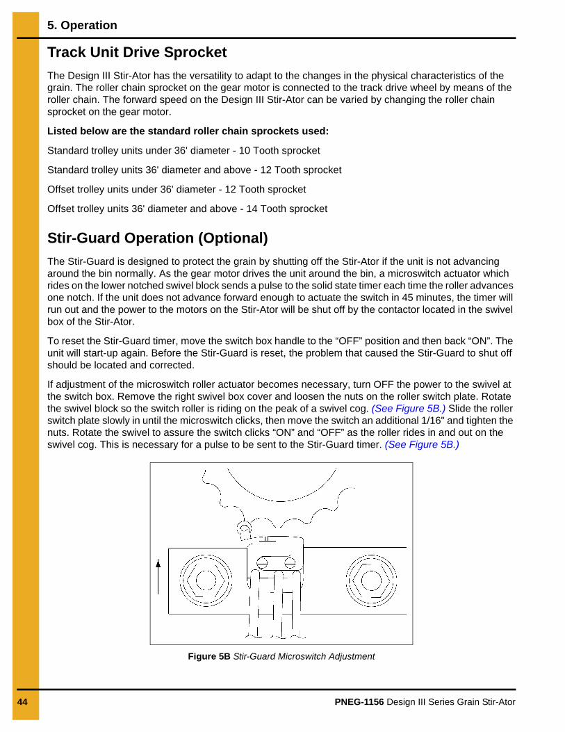
The Stir-Guard is designed to protect the grain by shutting off the Stir-Ator if the unit is not advancing around the bin normally. As the gear motor drives the unit around the bin, a microswitch actuator which rides on the lower notched swivel block sends a pulse to the solid state timer each time the roller advances one notch. If the unit does not advance forward enough to actuate the switch in 45 minutes, the timer will run out and the power to the motors on the Stir-Ator will be shut off by the contactor located in the swivel box of the Stir-Ator.
To reset the Stir-Guard timer, move the switch box handle to the “OFF” position and then back “ON”. The unit will start-up again. Before the Stir-Guard is reset, the problem that caused the Stir-Guard to shut off should be located and corrected.
If adjustment of the microswitch roller actuator becomes necessary, turn OFF the power to the swivel at the switch box. Remove the right swivel box cover and loosen the nuts on the roller switch plate. Rotate the swivel block so the switch roller is riding on the peak of a swivel cog. (See Figure 5B.) Slide the roller switch plate slowly in until the microswitch clicks, then move the switch an additional 1/16" and tighten the nuts. Rotate the swivel to assure the switch clicks “ON” and “OFF” as the roller rides in and out on the swivel cog. This is necessary for a pulse to be sent to the Stir-Guard timer. (See Figure 5B.)
Figure 5B Stir-Guard Microswitch Adjustment

5. Operation
PNEG-1156 Design III Series Grain Stir-Ator 45
Stir-Guard Option Installation Instructions
1. Disconnect power to the unit.
2. Remove the two (2) long swivel covers on the Stir-Ator yoke swivel housing.
3. Remove the two (2) self-tapping screws on the top of the swivel yoke enclosure. Position the solid state module #2EL1207 inside the top of the yoke swivel housing with the five (5) terminals on the module pointing toward the Stir-Ator swivel. Bolt the module onto the yoke where the self-tapping screws were removed using two (2) #8 x 1/2" screws and lock nuts.
4. Fasten the Stir-Guard assembly plate onto the swivel housing with the Stir-Guard contactor toward the swivel, secure with the #8 lock nuts. (Do not loosen the nuts holding the components on the Stir-Guard assembly plate.)
5. Place the two (2) small spacers onto the threaded studs welded in the swivel housing, next place the Stir-Guard switch and mounting plate onto the studs with the roller switch toward the cog swivel ring.
6. Adjust by putting the switch roller on the peak of a swivel cog. (See Figure 5B on Page 44.) Move the switch plate slowly inward until the roller switch clicks. After the click, move an additional 1/16", then tighten. Rotate the swivel, be sure the roller switch rides in and out freely and the switch clicks ON and OFF, as it passes over each cog. This is necessary for a pulse to be sent to the Stir-Guard timer. Without a pulse every 45 minutes, the Stir-Guard will shutdown the Stir-Ator operation.
7. Connect the roller switch wires to the Stir-Guard solid state module, matching the wire color to the module color coded markings.
8. Remove lead-in wires coming from the yoke pipe to the terminal strip EXCEPT THE GREEN WIRE. Cut off the spade terminal and strip the installation back 3/8". Reconnect these wires to the top and bottom lugs of the Stir-Guard contactor.
9. Connect the black jumper wires from the left side of the Stir-Guard contactor to the terminal strip.
10. Replace the swivel box covers.
11. Place the “STIR-GUARD” decals on the swivel covers over the decal already on the cover. DO NOT COVER THE CAUTION DECAL.
Storage
The Stir-Ator is an excellent tool to aid in the preservation of grain stored in the drying bin. Some experimentation has been done with storage of grain in the 16% range by use of the Stir-Ator to prevent formation of “hotspots” and insect hatchings. Such a program should be undertaken with caution and frequent inspections should be made.
Users of the Stir-Ator sometimes want to utilize more bin capacity for dry storage by heaping dried grain over the Stir-Ator. This is not recommended because the downward pressure of the grain on the Stir-Ator when the bin is emptied could bend or break parts of the machine or collapse the roof of the bin.
NOTE: Warranty will be voided if Stir-Ator is covered with grain.

5. Operation
46 PNEG-1156 Design III Series Grain Stir-Ator
Drying Guide
NOTE: Drying in grain depths of over 18' is not advised.
The recommendations below are for drying bins without wall-liners or air tubes. If such equipment is used, higher temperatures can be used without worry of bin wall moisture. Consequently, a faster fill rate also can be utilized.
Clean grain is very important to uniform drying.
Grain with a moisture of 20%-26% from the field is the most profitable harvest-drying range. Grain depths of up to 15' can be used in one fill using air only (no heat) or little heat.
A moisture of 27%-30% for grain can be successfully harvested and dried, however, caution should be used. Put up to 12' of grain into the bin during the first fill. This grain should be dried down to the 20%-25% level, then additional grain can be added.
When drying 27%-30% grain, it is advisable to keep the plenum (space between the floor and concrete foundation provided for air circulation for heating and ventilation of the product in the bin) temperature less than 50° above the ambient temperature for the first 4%-6% of moisture removed. After the initial moisture is lowered, higher temperatures can be utilized.
Drying grain with 30%-35% moisture is inefficient, but sometimes necessary. If this is the case, first clean the grain. Then, fill the bin to a depth of 12'-15'. Dry this grain to 20%-25%. Filling up to 18' after drying the 12'-15' depth will yield better results.
Grain testing over 35% moisture should not be harvested for drying except under emergency conditions. Harvest damage will be extensive and drying will be very difficult and expensive. The best course to be followed under these conditions is to fill slowly and supervise constantly.
NOTE: The higher the moisture of the grain, the lower the starting temperature should be to minimize wall condensation and ensure the highest quality of grain.
Bin liners or air tubes, depending on the severity of the condition, can be used successfully to control the problem of wet walls from condensation.
Check for moisture content of dried grain by taking and blending several samples across the top of the bin and from the grain coming up near the Stir-Ator auger.
Always have the Stir-Ator turned “OFF” when taking samples.DANGER
5. Operation
PNEG-1156 Design III Series Grain Stir-Ator 47
**Number of Stir-Ator Augers Versus Fan and Heater Sizes
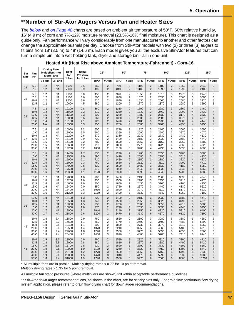
The below and on Page 48 charts are based on ambient air temperature of 50°F, 60% relative humidity, 16' (4.9 m) of corn and 7%-12% moisture removal (23.5%-16% final moisture). This chart is designed as a guide only. Fan performance will vary considerably from one manufacturer to another and other factors can change the approximate bushels per day. Choose from Stir-Ator models with two (2) or three (3) augers to fit bins from 18' (3.5 m) to 48' (14.6 m). Each model gives you all the exclusive Stir-Ator features that can turn a simple bin into a wet-holding tank, dryer and storage bin - all in one unit.
Heated Air (Heat Rise above Ambient Temperature-Fahrenheit) - Corn-16'
* All multiple fans are in parallel. Multiply drying rates x 0.77 for 10 point removal. Multiply drying rates x 1.35 for 5 point removal.
All multiple fan static pressures (where multipliers are shown) fall within acceptable performance guidelines.
** Stir-Ator down auger recommendations, as shown in the chart, are for stir-dry bins only. For grain flow continuous flow drying system application, please refer to grain flow drying chart for down auger recommendations.
Bin Size
Fan HP
Drying Rate Multipliers * for
More FansCFM for
1 Fan
Static Pressure for 1 Fan
25° 50° 75° 100° 125° 150°
2 Fans 3 Fans BPD # Aug BPD # Aug BPD # Aug BPD # Aug BPD # Aug BPD # Aug
18'5.07.5
1.21.2
NANA
66007100
3.53.9
360490
22
750810
22
11001180
22
14801590
22
18501990
33
22402400
33
21'
5.07.5
10.012.5
1.21.21.21.2
NANANANA
81009100920010600
3.03.63.64.5
450500510580
2222
920103010401200
2222
1350152015301770
2223
1810203020602370
3333
2270256025802980
3333
2740308031203590
3333
24'
7.510.010 C12.515 C20 C
1.31.21.51.31.4NA
NANANANANANA
102001100011300120001310015500
2.83.23.33.64.15.3
560610620660720850
222222
116012501280136014901760
222223
170018301880200021802580
333333
228024602530268029303460
333344
286030903170337036804350
444444
346037303830407044405250
444444
27'
7.510 C10.012.515 C20 C30 C
1.41.61.31.41.51.51.3
NANANANANANANA
10900120001220013100141001660019200
2.22.52.62.93.24.25.2
6006606707207809101060
2222222
1240136013801490160018802180
2222233
1820200020302180235027703200
3333334
2440268027302930315037204290
3334444
3060337034303680396046605390
4444444
3690407041304440478046206500
4444444
30'
7.510 C10.012.515 C20 C30 C
1.61.71.51.51.61.61.6
NANANANANANANA
11400125001290013900149001760020300
1.72.02.12.32.63.34.1
6306907107608209701120
2222222
1290142014601580169020002300
2222333
1900208021502320248029403390
3333344
2550279028803110333039304540
3444444
3200351036203900418049405700
4444444
3680423043704710505059606880
4444444
33'
10 C10.012.515 C20 C30 C
1.71.61.61.61.61.6
NANANANANANA
128001320014600154001840021200
1.61.61.92.02.63.3
70073080085010101170
222222
145015001660175020902400
222333
213022002430257030703530
333344
286029503260344041104740
444444
359037104100433051705950
444444
434044704950522062307180
444444
36'
10 C10.012.515 C20 C30 C
1.81.71.71.71.71.7
NANANANANANA
131001350015000158001890021800
1.31.31.51.62.12.6
72074083087010401200
222222
149015301700179021402470
223333
218022502500263031503630
333466
293030203350353042204870
446666
368037904210444053106120
666666
444045705080535064007390
666666
42'
10.012.515.020 C30 C40 C
1.81.81.81.81.81.8
2.42.32.42.42.42.4
138001560016400195002260026400
0.91.11.11.41.82.2
760860900107012401450
222223
156017701860221025602990
233336
230026002730325037704400
336666
308034903670436050505900
666666
388043804610548063507410
666666
468052905560661076608940
666666
48'
10.012.515 C20 C30 C40 C50 C
1.91.81.91.91.81.91.8
2.72.52.62.62.52.62.4
13900160001670019900231002680031600
0.60.80.81.01.21.51.9
7608809201100127014701740
2222333
1580181018902260262030403580
2333666
2320267027903320385044705270
3666666
3110358037304450516059907060
6666666
3900449046905590649075308800
6666666
471054205660674078309080
10710
6666666
5. Operation
48 PNEG-1156 Design III Series Grain Stir-Ator
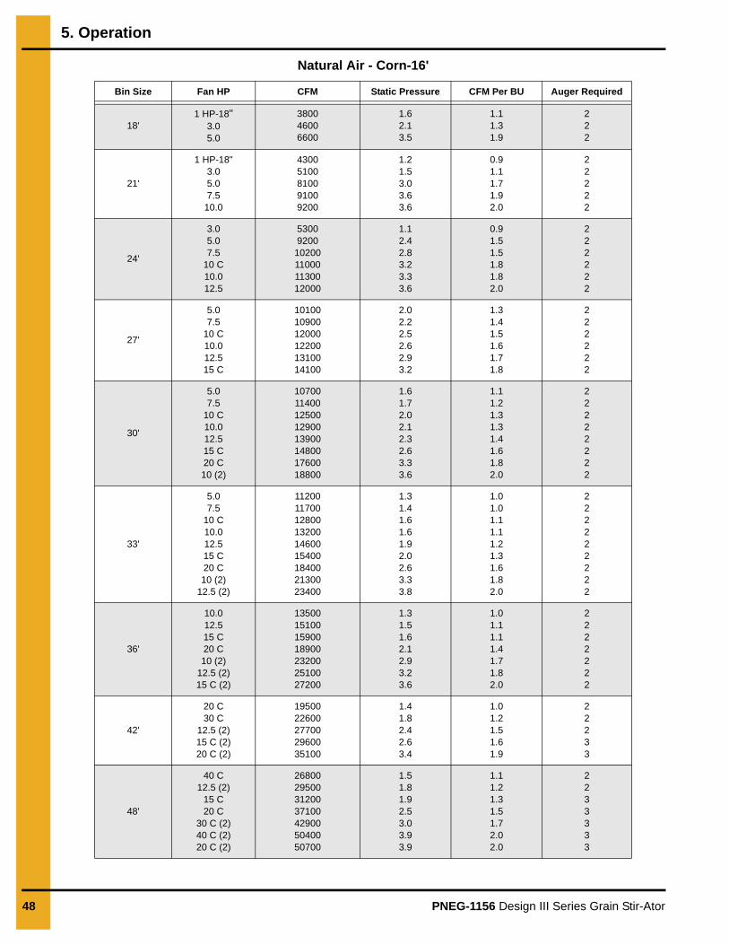
Natural Air - Corn-16'
Bin Size Fan HP CFM Static Pressure CFM Per BU Auger Required
18'1 HP-18"
3.05.0
380046006600
1.62.13.5
1.11.31.9
222
21'
1 HP-18"3.05.07.5
10.0
43005100810091009200
1.21.53.03.63.6
0.91.11.71.92.0
22222
24'
3.05.07.5
10 C10.012.5
53009200
10200110001130012000
1.12.42.83.23.33.6
0.91.51.51.81.82.0
222222
27'
5.07.5
10 C10.012.515 C
101001090012000122001310014100
2.02.22.52.62.93.2
1.31.41.51.61.71.8
222222
30'
5.07.5
10 C10.012.515 C20 C10 (2)
1070011400125001290013900148001760018800
1.61.72.02.12.32.63.33.6
1.11.21.31.31.41.61.82.0
22222222
33'
5.07.5
10 C10.012.515 C20 C10 (2)
12.5 (2)
112001170012800132001460015400184002130023400
1.31.41.61.61.92.02.63.33.8
1.01.01.11.11.21.31.61.82.0
222222222
36'
10.012.515 C20 C10 (2)
12.5 (2)15 C (2)
13500151001590018900232002510027200
1.31.51.62.12.93.23.6
1.01.11.11.41.71.82.0
2222222
42'
20 C30 C
12.5 (2)15 C (2)20 C (2)
1950022600277002960035100
1.41.82.42.63.4
1.01.21.51.61.9
22233
48'
40 C12.5 (2)
15 C20 C
30 C (2)40 C (2)20 C (2)
26800295003120037100429005040050700
1.51.81.92.53.03.93.9
1.11.21.31.51.72.02.0
2233333
PNEG-1156 Design III Series Grain Stir-Ator 49
6. Parts List
1. Design III Stir-Ator Track Unit (See Pages 50 and 51.)
2. Design III Stir-Ator Switch Boxes and Suspension (See Pages 52 and 53.)
3. Design III Stir-Ator Yoke (See Pages 54-57.)
4. Design III Stir-Ator Double Auger Trolley (See Pages 58, 60-62.)
5. Design III Stir-Ator Triple Auger Trolley (See Pages 59-62.)
6. Stir-Ator Guard Option - 230V (See Page 63.)
6. Parts List
50 PNEG-1156 Design III Series Grain Stir-Ator
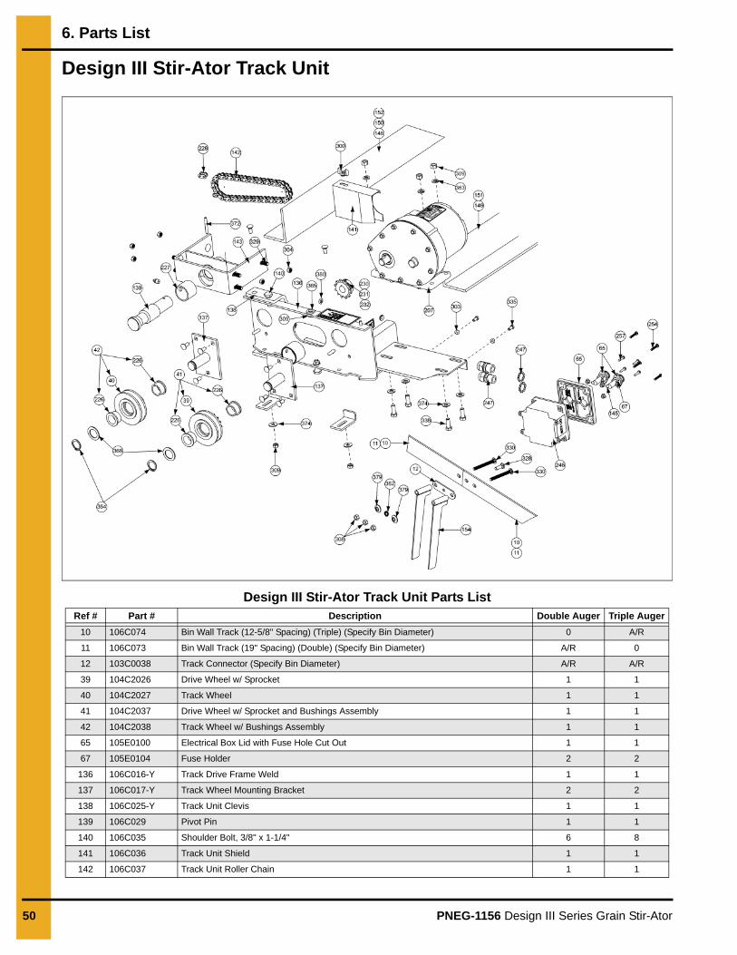
Design III Stir-Ator Track Unit
Design III Stir-Ator Track Unit Parts ListRef # Part # Description Double Auger Triple Auger
10 106C074 Bin Wall Track (12-5/8" Spacing) (Triple) (Specify Bin Diameter) 0 A/R
11 106C073 Bin Wall Track (19" Spacing) (Double) (Specify Bin Diameter) A/R 0
12 103C0038 Track Connector (Specify Bin Diameter) A/R A/R
39 104C2026 Drive Wheel w/ Sprocket 1 1
40 104C2027 Track Wheel 1 1
41 104C2037 Drive Wheel w/ Sprocket and Bushings Assembly 1 1
42 104C2038 Track Wheel w/ Bushings Assembly 1 1
65 105E0100 Electrical Box Lid with Fuse Hole Cut Out 1 1
67 105E0104 Fuse Holder 2 2
136 106C016-Y Track Drive Frame Weld 1 1
137 106C017-Y Track Wheel Mounting Bracket 2 2
138 106C025-Y Track Unit Clevis 1 1
139 106C029 Pivot Pin 1 1
140 106C035 Shoulder Bolt, 3/8" x 1-1/4" 6 8
141 106C036 Track Unit Shield 1 1
142 106C037 Track Unit Roller Chain 1 1
6. Parts List
PNEG-1156 Design III Series Grain Stir-Ator 51
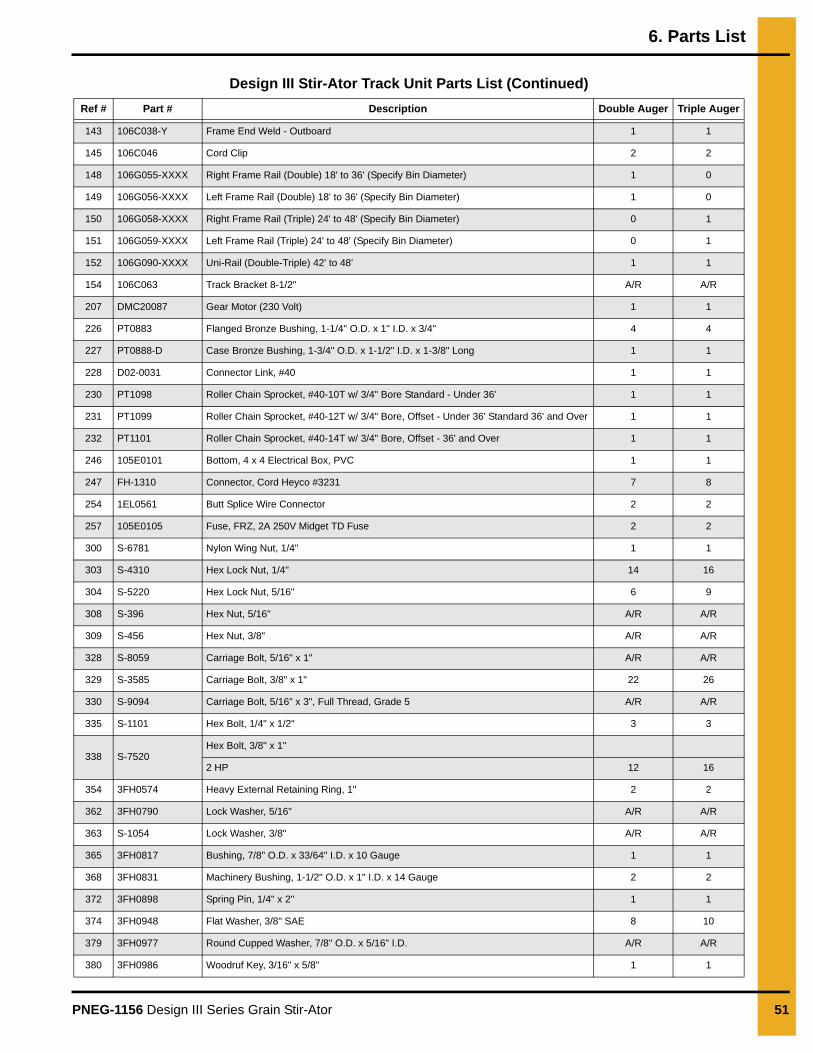
Design III Stir-Ator Track Unit Parts List (Continued)
Ref # Part # Description Double Auger Triple Auger
143 106C038-Y Frame End Weld - Outboard 1 1
145 106C046 Cord Clip 2 2
148 106G055-XXXX Right Frame Rail (Double) 18' to 36' (Specify Bin Diameter) 1 0
149 106G056-XXXX Left Frame Rail (Double) 18' to 36' (Specify Bin Diameter) 1 0
150 106G058-XXXX Right Frame Rail (Triple) 24' to 48' (Specify Bin Diameter) 0 1
151 106G059-XXXX Left Frame Rail (Triple) 24' to 48' (Specify Bin Diameter) 0 1
152 106G090-XXXX Uni-Rail (Double-Triple) 42' to 48' 1 1
154 106C063 Track Bracket 8-1/2" A/R A/R
207 DMC20087 Gear Motor (230 Volt) 1 1
226 PT0883 Flanged Bronze Bushing, 1-1/4" O.D. x 1" I.D. x 3/4" 4 4
227 PT0888-D Case Bronze Bushing, 1-3/4" O.D. x 1-1/2" I.D. x 1-3/8" Long 1 1
228 D02-0031 Connector Link, #40 1 1
230 PT1098 Roller Chain Sprocket, #40-10T w/ 3/4" Bore Standard - Under 36' 1 1
231 PT1099 Roller Chain Sprocket, #40-12T w/ 3/4" Bore, Offset - Under 36' Standard 36' and Over 1 1
232 PT1101 Roller Chain Sprocket, #40-14T w/ 3/4" Bore, Offset - 36' and Over 1 1
246 105E0101 Bottom, 4 x 4 Electrical Box, PVC 1 1
247 FH-1310 Connector, Cord Heyco #3231 7 8
254 1EL0561 Butt Splice Wire Connector 2 2
257 105E0105 Fuse, FRZ, 2A 250V Midget TD Fuse 2 2
300 S-6781 Nylon Wing Nut, 1/4" 1 1
303 S-4310 Hex Lock Nut, 1/4" 14 16
304 S-5220 Hex Lock Nut, 5/16" 6 9
308 S-396 Hex Nut, 5/16" A/R A/R
309 S-456 Hex Nut, 3/8" A/R A/R
328 S-8059 Carriage Bolt, 5/16" x 1" A/R A/R
329 S-3585 Carriage Bolt, 3/8" x 1" 22 26
330 S-9094 Carriage Bolt, 5/16" x 3", Full Thread, Grade 5 A/R A/R
335 S-1101 Hex Bolt, 1/4" x 1/2" 3 3
338 S-7520Hex Bolt, 3/8" x 1"
2 HP 12 16
354 3FH0574 Heavy External Retaining Ring, 1" 2 2
362 3FH0790 Lock Washer, 5/16" A/R A/R
363 S-1054 Lock Washer, 3/8" A/R A/R
365 3FH0817 Bushing, 7/8" O.D. x 33/64" I.D. x 10 Gauge 1 1
368 3FH0831 Machinery Bushing, 1-1/2" O.D. x 1" I.D. x 14 Gauge 2 2
372 3FH0898 Spring Pin, 1/4" x 2" 1 1
374 3FH0948 Flat Washer, 3/8" SAE 8 10
379 3FH0977 Round Cupped Washer, 7/8" O.D. x 5/16" I.D. A/R A/R
380 3FH0986 Woodruf Key, 3/16" x 5/8" 1 1
6. Parts List
52 PNEG-1156 Design III Series Grain Stir-Ator
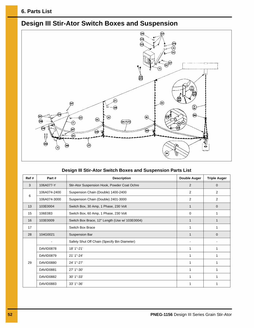
Design III Stir-Ator Switch Boxes and Suspension
Design III Stir-Ator Switch Boxes and Suspension Parts List
Ref # Part # Description Double Auger Triple Auger
3 106A077-Y Stir-Ator Suspension Hook, Powder Coat Ochre 2 0
6106A074-2400 Suspension Chain (Double) 1400-2400 2 2
106A074-3000 Suspension Chain (Double) 2401-3000 2 2
13 103E0004 Switch Box, 30 Amp, 1 Phase, 230 Volt 1 0
15 106E083 Switch Box, 60 Amp, 1 Phase, 230 Volt 0 1
16 103E0009 Switch Box Brace, 12" Length (Use w/ 103E0004) 1 1
17 Switch Box Brace 1 1
28 104G0021 Suspension Bar 1 0
29
- Safety Shut Off Chain (Specify Bin Diameter) - -
DAVID0878 18' 1''-21' 1 1
DAVID0879 21' 1''-24' 1 1
DAVID0880 24' 1''-27' 1 1
DAVID0881 27' 1''-30' 1 1
DAVID0882 30' 1''-33' 1 1
DAVID0883 33' 1''-36' 1 1
6. Parts List
PNEG-1156 Design III Series Grain Stir-Ator 53
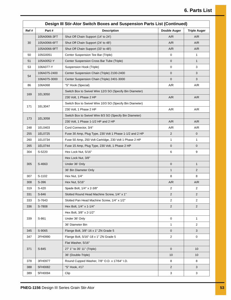
Design III Stir-Ator Switch Boxes and Suspension Parts List (Continued)
Ref # Part # Description Double Auger Triple Auger
30
105A0066-3FT Shut Off Chain Support (14' to 24') A/R A/R
105A0066-6FT Shut Off Chain Support (24' to 48') A/R A/R
105A0066-9FT Shut Off Chain Support (33' to 48') A/R A/R
50 105G0051 Center Suspension Tee Bar (Triple) 0 1
51 105A0052-Y Center Suspension Cross Bar Tube (Triple) 0 1
53 106A077-Y Suspension Hook (Triple) 0 3
54106A075-2400 Center Suspension Chain (Triple) 2100-2400 0 3
106A075-3000 Center Suspension Chain (Triple) 2401-3000 0 3
86 106A068 “S” Hook (Special) A/R A/R
169 1EL3050Switch Box to Swivel Wire 12/3 SO (Specify Bin Diameter)
230 Volt, 1 Phase 2 HP A/R A/R
171 1EL3047Switch Box to Swivel Wire 10/3 SO (Specify Bin Diameter)
230 Volt, 1 Phase 2 HP A/R A/R
173 1EL3058Switch Box to Swivel Wire 8/3 SO (Specify Bin Diameter)
230 Volt, 1 Phase 1-1/2 HP and 2 HP A/R A/R
248 1EL0403 Cord Connector, 3/4'' A/R A/R
255 1EL0725 Fuse 30 Amp, Plug Type, 230 Volt 1 Phase 1-1/2 and 2 HP 2 0
260 1EL0734 Fuse 50 Amp, 250 Volt Cartridge, 230 Volt 1 Phase 2 HP 1 1
265 1EL0744 Fuse 15 Amp, Plug Type, 230 Volt, 1 Phase 2 HP 0 0
304 S-5220 Hex Lock Nut, 5/16'' 6 9
305 S-4663
Hex Lock Nut, 3/8''
Under 36' Only 0 1
36' Bin Diameter Only 1 2
307 S-1102 Hex Nut, 1/4'' 8 8
308 S-396 Hex Nut, 5/16'' A/R A/R
319 S-420 Spade Bolt, 1/4'' x 2-3/8'' 2 2
331 S-846 Slotted Round Head Machine Screw, 1/4'' x 1'' 2 2
333 S-7643 Slotted Pan Head Machine Screw, 1/4'' x 1/2'' 2 2
336 S-7808 Hex Bolt, 1/4'' x 1-1/4'' 2 2
339 S-861
Hex Bolt, 3/8'' x 2-1/2''
Under 36' Only 0 1
36' Diameter Bin 1 2
345 S-9065 Flange Bolt, 3/8"-16 x 1" ZN Grade 5 0 3
347 2FH0990 Flange Bolt, 5/16"-18 x 1" ZN Grade 5 2 0
371 S-845
Flat Washer, 5/16''
27' 1'' to 35' 11'' (Triple) 0 10
36' (Double-Triple) 10 10
378 3FH0977 Round Cupped Washer, 7/8'' O.D. x 17/64'' I.D. 8 8
388 5FH0082 “S” Hook, #17 2 3
389 5FH0094 Clip 3 3
6. Parts List
54 PNEG-1156 Design III Series Grain Stir-Ator
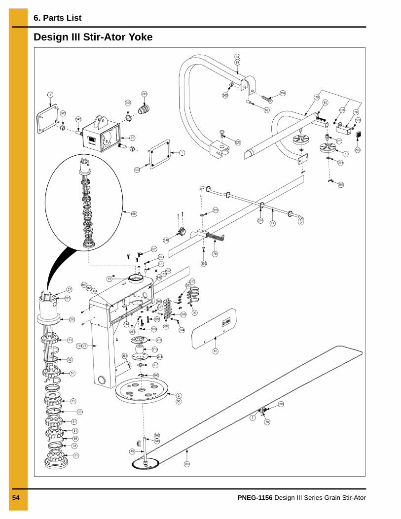
Design III Stir-Ator Yoke
6. Parts List
PNEG-1156 Design III Series Grain Stir-Ator 55
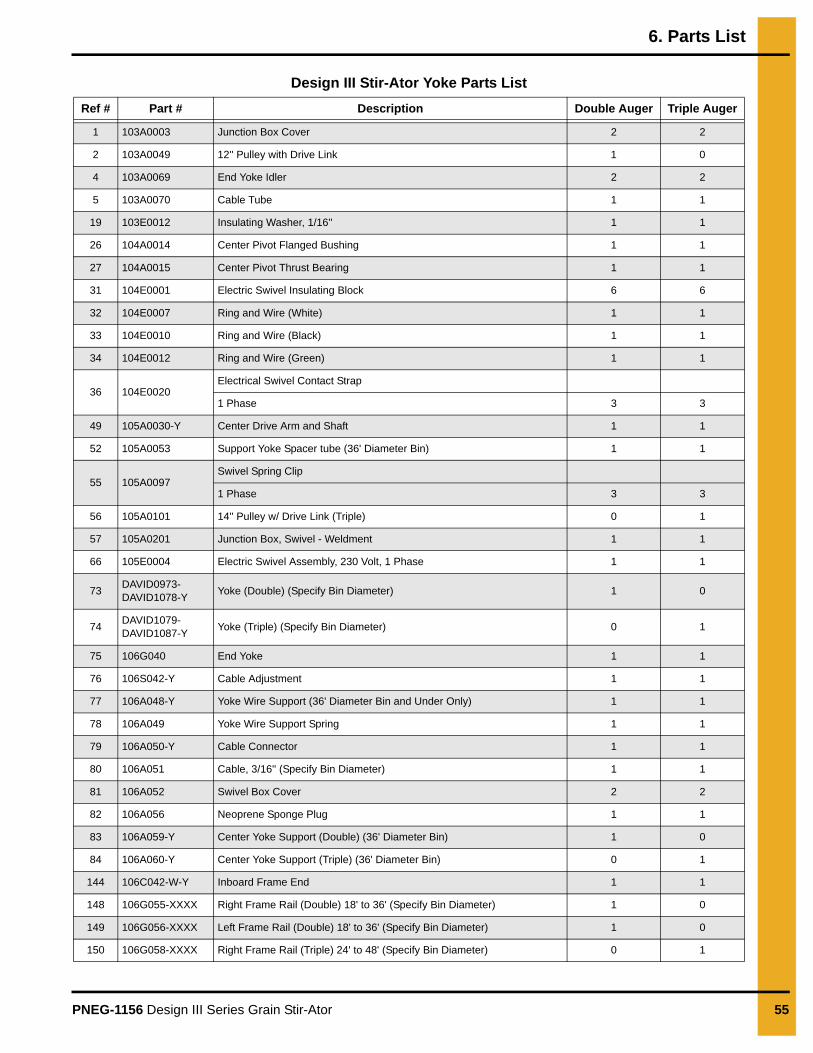
Design III Stir-Ator Yoke Parts List
Ref # Part # Description Double Auger Triple Auger
1 103A0003 Junction Box Cover 2 2
2 103A0049 12'' Pulley with Drive Link 1 0
4 103A0069 End Yoke Idler 2 2
5 103A0070 Cable Tube 1 1
19 103E0012 Insulating Washer, 1/16'' 1 1
26 104A0014 Center Pivot Flanged Bushing 1 1
27 104A0015 Center Pivot Thrust Bearing 1 1
31 104E0001 Electric Swivel Insulating Block 6 6
32 104E0007 Ring and Wire (White) 1 1
33 104E0010 Ring and Wire (Black) 1 1
34 104E0012 Ring and Wire (Green) 1 1
36 104E0020Electrical Swivel Contact Strap
1 Phase 3 3
49 105A0030-Y Center Drive Arm and Shaft 1 1
52 105A0053 Support Yoke Spacer tube (36' Diameter Bin) 1 1
55 105A0097Swivel Spring Clip
1 Phase 3 3
56 105A0101 14'' Pulley w/ Drive Link (Triple) 0 1
57 105A0201 Junction Box, Swivel - Weldment 1 1
66 105E0004 Electric Swivel Assembly, 230 Volt, 1 Phase 1 1
73DAVID0973-DAVID1078-Y
Yoke (Double) (Specify Bin Diameter) 1 0
74DAVID1079-DAVID1087-Y
Yoke (Triple) (Specify Bin Diameter) 0 1
75 106G040 End Yoke 1 1
76 106S042-Y Cable Adjustment 1 1
77 106A048-Y Yoke Wire Support (36' Diameter Bin and Under Only) 1 1
78 106A049 Yoke Wire Support Spring 1 1
79 106A050-Y Cable Connector 1 1
80 106A051 Cable, 3/16'' (Specify Bin Diameter) 1 1
81 106A052 Swivel Box Cover 2 2
82 106A056 Neoprene Sponge Plug 1 1
83 106A059-Y Center Yoke Support (Double) (36' Diameter Bin) 1 0
84 106A060-Y Center Yoke Support (Triple) (36' Diameter Bin) 0 1
144 106C042-W-Y Inboard Frame End 1 1
148 106G055-XXXX Right Frame Rail (Double) 18' to 36' (Specify Bin Diameter) 1 0
149 106G056-XXXX Left Frame Rail (Double) 18' to 36' (Specify Bin Diameter) 1 0
150 106G058-XXXX Right Frame Rail (Triple) 24' to 48' (Specify Bin Diameter) 0 1
6. Parts List
56 PNEG-1156 Design III Series Grain Stir-Ator
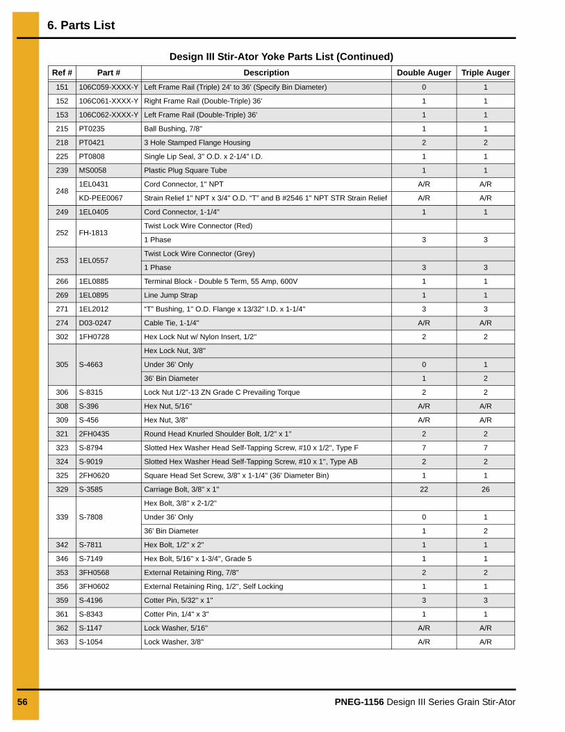
Design III Stir-Ator Yoke Parts List (Continued)
Ref # Part # Description Double Auger Triple Auger
151 106C059-XXXX-Y Left Frame Rail (Triple) 24' to 36' (Specify Bin Diameter) 0 1
152 106C061-XXXX-Y Right Frame Rail (Double-Triple) 36' 1 1
153 106C062-XXXX-Y Left Frame Rail (Double-Triple) 36' 1 1
215 PT0235 Ball Bushing, 7/8'' 1 1
218 PT0421 3 Hole Stamped Flange Housing 2 2
225 PT0808 Single Lip Seal, 3'' O.D. x 2-1/4'' I.D. 1 1
239 MS0058 Plastic Plug Square Tube 1 1
2481EL0431 Cord Connector, 1'' NPT A/R A/R
KD-PEE0067 Strain Relief 1" NPT x 3/4" O.D. “T” and B #2546 1" NPT STR Strain Relief A/R A/R
249 1EL0405 Cord Connector, 1-1/4'' 1 1
252 FH-1813Twist Lock Wire Connector (Red)
1 Phase 3 3
253 1EL0557Twist Lock Wire Connector (Grey)
1 Phase 3 3
266 1EL0885 Terminal Block - Double 5 Term, 55 Amp, 600V 1 1
269 1EL0895 Line Jump Strap 1 1
271 1EL2012 “T” Bushing, 1'' O.D. Flange x 13/32'' I.D. x 1-1/4'' 3 3
274 D03-0247 Cable Tie, 1-1/4'' A/R A/R
302 1FH0728 Hex Lock Nut w/ Nylon Insert, 1/2'' 2 2
305 S-4663
Hex Lock Nut, 3/8''
Under 36' Only 0 1
36' Bin Diameter 1 2
306 S-8315 Lock Nut 1/2"-13 ZN Grade C Prevailing Torque 2 2
308 S-396 Hex Nut, 5/16'' A/R A/R
309 S-456 Hex Nut, 3/8'' A/R A/R
321 2FH0435 Round Head Knurled Shoulder Bolt, 1/2'' x 1'' 2 2
323 S-8794 Slotted Hex Washer Head Self-Tapping Screw, #10 x 1/2'', Type F 7 7
324 S-9019 Slotted Hex Washer Head Self-Tapping Screw, #10 x 1'', Type AB 2 2
325 2FH0620 Square Head Set Screw, 3/8'' x 1-1/4'' (36' Diameter Bin) 1 1
329 S-3585 Carriage Bolt, 3/8'' x 1'' 22 26
339 S-7808
Hex Bolt, 3/8'' x 2-1/2''
Under 36' Only 0 1
36' Bin Diameter 1 2
342 S-7811 Hex Bolt, 1/2'' x 2'' 1 1
346 S-7149 Hex Bolt, 5/16'' x 1-3/4'', Grade 5 1 1
353 3FH0568 External Retaining Ring, 7/8'' 2 2
356 3FH0602 External Retaining Ring, 1/2'', Self Locking 1 1
359 S-4196 Cotter Pin, 5/32'' x 1'' 3 3
361 S-8343 Cotter Pin, 1/4'' x 3'' 1 1
362 S-1147 Lock Washer, 5/16'' A/R A/R
363 S-1054 Lock Washer, 3/8'' A/R A/R
6. Parts List
PNEG-1156 Design III Series Grain Stir-Ator 57
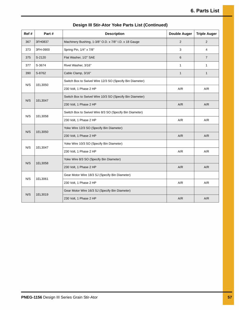
Design III Stir-Ator Yoke Parts List (Continued)
Ref # Part # Description Double Auger Triple Auger
367 3FH0837 Machinery Bushing, 1-3/8'' O.D. x 7/8'' I.D. x 18 Gauge 2 2
373 3FH-0900 Spring Pin, 1/4'' x 7/8'' 3 4
375 S-2120 Flat Washer, 1/2'' SAE 6 7
377 S-3674 Rivet Washer, 3/16'' 1 1
390 S-8762 Cable Clamp, 3/16'' 1 1
N/S 1EL3050Switch Box to Swivel Wire 12/3 SO (Specify Bin Diameter)
230 Volt, 1 Phase 2 HP A/R A/R
N/S 1EL3047Switch Box to Swivel Wire 10/3 SO (Specify Bin Diameter)
230 Volt, 1 Phase 2 HP A/R A/R
N/S 1EL3058Switch Box to Swivel Wire 8/3 SO (Specify Bin Diameter)
230 Volt, 1 Phase 2 HP A/R A/R
N/S 1EL3050Yoke Wire 12/3 SO (Specify Bin Diameter)
230 Volt, 1 Phase 2 HP A/R A/R
N/S 1EL3047Yoke Wire 10/3 SO (Specify Bin Diameter)
230 Volt, 1 Phase 2 HP A/R A/R
N/S 1EL3058Yoke Wire 8/3 SO (Specify Bin Diameter)
230 Volt, 1 Phase 2 HP A/R A/R
N/S 1EL3061Gear Motor Wire 18/3 SJ (Specify Bin Diameter)
230 Volt, 1 Phase 2 HP A/R A/R
N/S 1EL3019Gear Motor Wire 16/3 SJ (Specify Bin Diameter)
230 Volt, 1 Phase 2 HP A/R A/R
6. Parts List
58 PNEG-1156 Design III Series Grain Stir-Ator
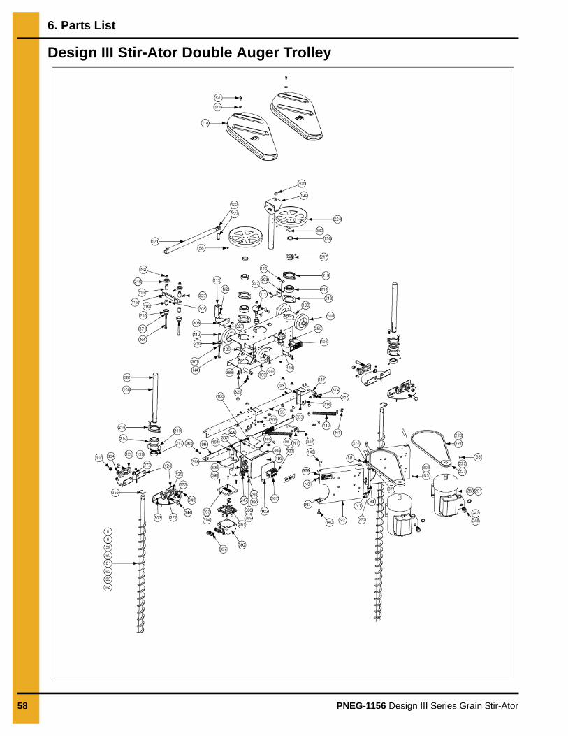
Design III Stir-Ator Double Auger Trolley
6. Parts List
PNEG-1156 Design III Series Grain Stir-Ator 59
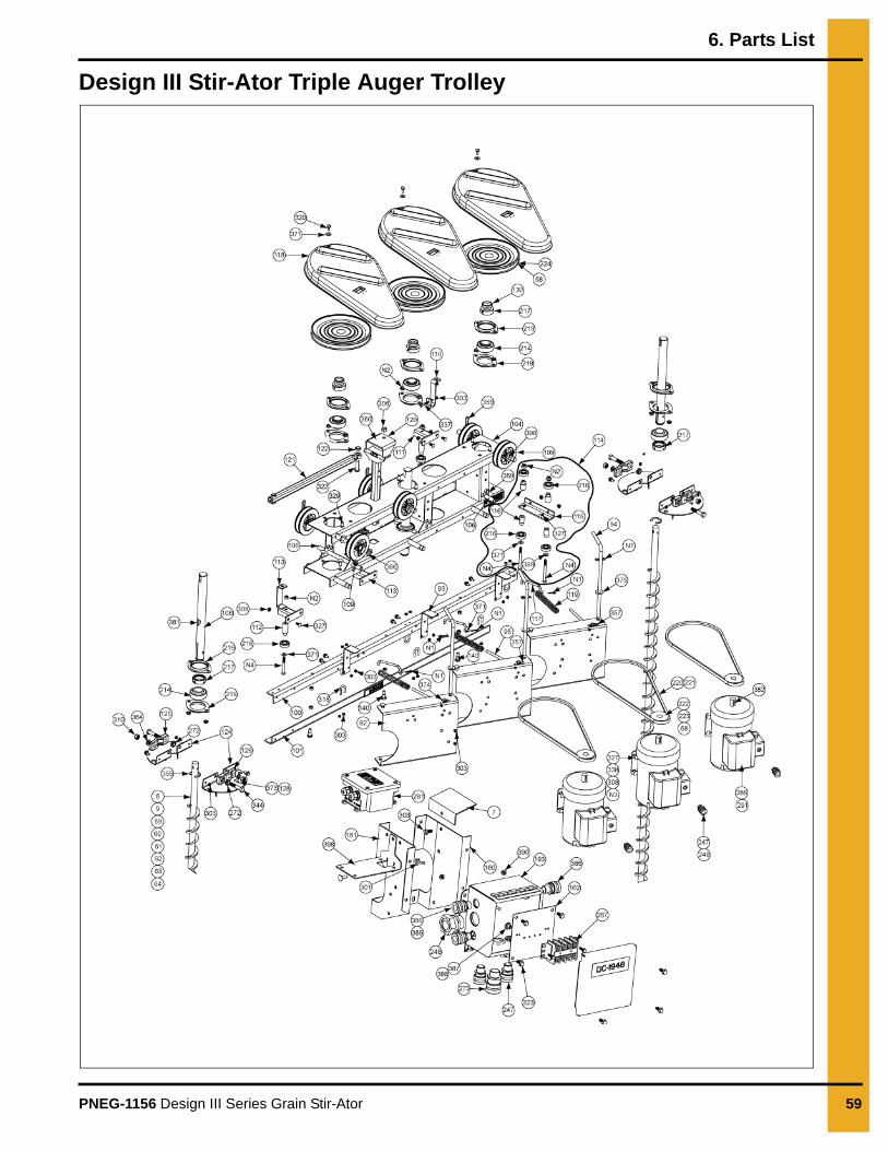
Design III Stir-Ator Triple Auger Trolley
6. Parts List
60 PNEG-1156 Design III Series Grain Stir-Ator
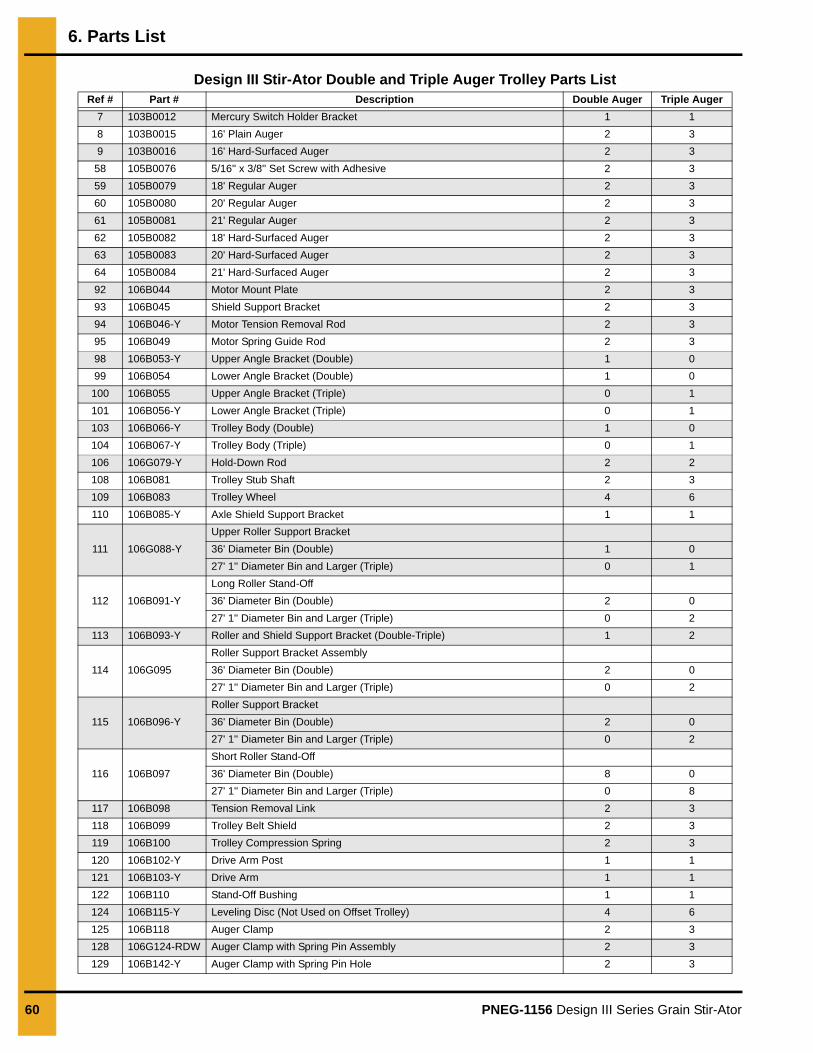
Design III Stir-Ator Double and Triple Auger Trolley Parts ListRef # Part # Description Double Auger Triple Auger
7 103B0012 Mercury Switch Holder Bracket 1 1
8 103B0015 16' Plain Auger 2 3
9 103B0016 16' Hard-Surfaced Auger 2 3
58 105B0076 5/16'' x 3/8'' Set Screw with Adhesive 2 3
59 105B0079 18' Regular Auger 2 3
60 105B0080 20' Regular Auger 2 3
61 105B0081 21' Regular Auger 2 3
62 105B0082 18' Hard-Surfaced Auger 2 3
63 105B0083 20' Hard-Surfaced Auger 2 3
64 105B0084 21' Hard-Surfaced Auger 2 3
92 106B044 Motor Mount Plate 2 3
93 106B045 Shield Support Bracket 2 3
94 106B046-Y Motor Tension Removal Rod 2 3
95 106B049 Motor Spring Guide Rod 2 3
98 106B053-Y Upper Angle Bracket (Double) 1 0
99 106B054 Lower Angle Bracket (Double) 1 0
100 106B055 Upper Angle Bracket (Triple) 0 1
101 106B056-Y Lower Angle Bracket (Triple) 0 1
103 106B066-Y Trolley Body (Double) 1 0
104 106B067-Y Trolley Body (Triple) 0 1
106 106G079-Y Hold-Down Rod 2 2
108 106B081 Trolley Stub Shaft 2 3
109 106B083 Trolley Wheel 4 6
110 106B085-Y Axle Shield Support Bracket 1 1
111 106G088-Y
Upper Roller Support Bracket
36' Diameter Bin (Double) 1 0
27' 1'' Diameter Bin and Larger (Triple) 0 1
112 106B091-Y
Long Roller Stand-Off
36' Diameter Bin (Double) 2 0
27' 1'' Diameter Bin and Larger (Triple) 0 2
113 106B093-Y Roller and Shield Support Bracket (Double-Triple) 1 2
114 106G095
Roller Support Bracket Assembly
36' Diameter Bin (Double) 2 0
27' 1'' Diameter Bin and Larger (Triple) 0 2
115 106B096-Y
Roller Support Bracket
36' Diameter Bin (Double) 2 0
27' 1'' Diameter Bin and Larger (Triple) 0 2
116 106B097
Short Roller Stand-Off
36' Diameter Bin (Double) 8 0
27' 1'' Diameter Bin and Larger (Triple) 0 8
117 106B098 Tension Removal Link 2 3
118 106B099 Trolley Belt Shield 2 3
119 106B100 Trolley Compression Spring 2 3
120 106B102-Y Drive Arm Post 1 1
121 106B103-Y Drive Arm 1 1
122 106B110 Stand-Off Bushing 1 1
124 106B115-Y Leveling Disc (Not Used on Offset Trolley) 4 6
125 106B118 Auger Clamp 2 3
128 106G124-RDW Auger Clamp with Spring Pin Assembly 2 3
129 106B142-Y Auger Clamp with Spring Pin Hole 2 3
6. Parts List
PNEG-1156 Design III Series Grain Stir-Ator 61
Design III Stir-Ator Double and Triple Auger Trolley Parts List (Continued)Ref # Part # Description Double Auger Triple Auger
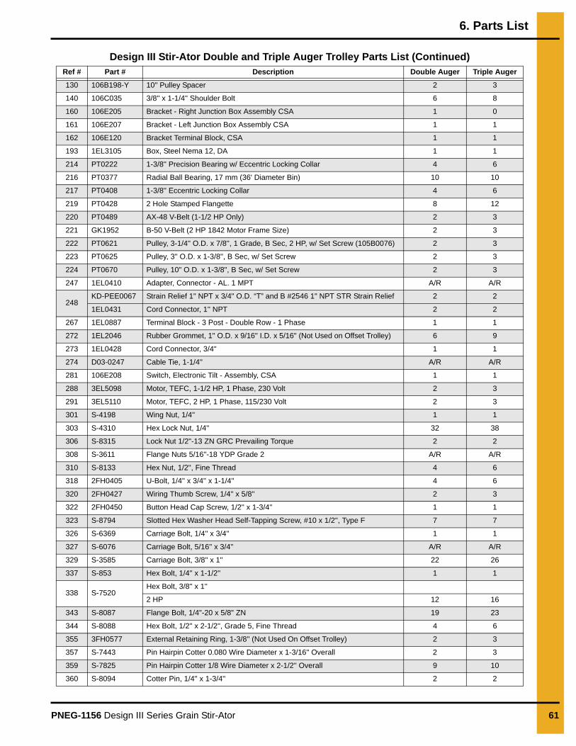
130 106B198-Y 10'' Pulley Spacer 2 3
140 106C035 3/8'' x 1-1/4'' Shoulder Bolt 6 8
160 106E205 Bracket - Right Junction Box Assembly CSA 1 0
161 106E207 Bracket - Left Junction Box Assembly CSA 1 1
162 106E120 Bracket Terminal Block, CSA 1 1
193 1EL3105 Box, Steel Nema 12, DA 1 1
214 PT0222 1-3/8'' Precision Bearing w/ Eccentric Locking Collar 4 6
216 PT0377 Radial Ball Bearing, 17 mm (36' Diameter Bin) 10 10
217 PT0408 1-3/8'' Eccentric Locking Collar 4 6
219 PT0428 2 Hole Stamped Flangette 8 12
220 PT0489 AX-48 V-Belt (1-1/2 HP Only) 2 3
221 GK1952 B-50 V-Belt (2 HP 1842 Motor Frame Size) 2 3
222 PT0621 Pulley, 3-1/4'' O.D. x 7/8'', 1 Grade, B Sec, 2 HP, w/ Set Screw (105B0076) 2 3
223 PT0625 Pulley, 3'' O.D. x 1-3/8'', B Sec, w/ Set Screw 2 3
224 PT0670 Pulley, 10" O.D. x 1-3/8", B Sec, w/ Set Screw 2 3
247 1EL0410 Adapter, Connector - AL. 1 MPT A/R A/R
248KD-PEE0067 Strain Relief 1" NPT x 3/4" O.D. “T” and B #2546 1" NPT STR Strain Relief 2 2
1EL0431 Cord Connector, 1'' NPT 2 2
267 1EL0887 Terminal Block - 3 Post - Double Row - 1 Phase 1 1
272 1EL2046 Rubber Grommet, 1'' O.D. x 9/16'' I.D. x 5/16'' (Not Used on Offset Trolley) 6 9
273 1EL0428 Cord Connector, 3/4" 1 1
274 D03-0247 Cable Tie, 1-1/4'' A/R A/R
281 106E208 Switch, Electronic Tilt - Assembly, CSA 1 1
288 3EL5098 Motor, TEFC, 1-1/2 HP, 1 Phase, 230 Volt 2 3
291 3EL5110 Motor, TEFC, 2 HP, 1 Phase, 115/230 Volt 2 3
301 S-4198 Wing Nut, 1/4'' 1 1
303 S-4310 Hex Lock Nut, 1/4'' 32 38
306 S-8315 Lock Nut 1/2"-13 ZN GRC Prevailing Torque 2 2
308 S-3611 Flange Nuts 5/16''-18 YDP Grade 2 A/R A/R
310 S-8133 Hex Nut, 1/2'', Fine Thread 4 6
318 2FH0405 U-Bolt, 1/4'' x 3/4'' x 1-1/4'' 4 6
320 2FH0427 Wiring Thumb Screw, 1/4'' x 5/8'' 2 3
322 2FH0450 Button Head Cap Screw, 1/2'' x 1-3/4'' 1 1
323 S-8794 Slotted Hex Washer Head Self-Tapping Screw, #10 x 1/2'', Type F 7 7
326 S-6369 Carriage Bolt, 1/4'' x 3/4'' 1 1
327 S-6076 Carriage Bolt, 5/16'' x 3/4'' A/R A/R
329 S-3585 Carriage Bolt, 3/8'' x 1'' 22 26
337 S-853 Hex Bolt, 1/4'' x 1-1/2'' 1 1
338 S-7520Hex Bolt, 3/8'' x 1''
2 HP 12 16
343 S-8087 Flange Bolt, 1/4"-20 x 5/8" ZN 19 23
344 S-8088 Hex Bolt, 1/2'' x 2-1/2'', Grade 5, Fine Thread 4 6
355 3FH0577 External Retaining Ring, 1-3/8'' (Not Used On Offset Trolley) 2 3
357 S-7443 Pin Hairpin Cotter 0.080 Wire Diameter x 1-3/16'' Overall 2 3
359 S-7825 Pin Hairpin Cotter 1/8 Wire Diameter x 2-1/2'' Overall 9 10
360 S-8094 Cotter Pin, 1/4'' x 1-3/4'' 2 2
6. Parts List
62 PNEG-1156 Design III Series Grain Stir-Ator
Design III Stir-Ator Double and Triple Auger Trolley Parts List (Continued)
Ref # Part # Description Double Auger Triple Auger
364 S-236 Lock Washer, 1/2'' 4 6
366 3FH0828 Machinery Bushing, 1-1/4'' O.D. x 3/4'' I.D. x 14 Gauge 8 12
369 3FH0851 Plastic Flat Washer, 29/32'' O.D. x 1/2'' I.D. x 5/64'' 4 6
371 S-845
Flat Washer, 5/16''
27' 1'' to 35' 11'' 4 12
36' (Double-Triple) 10 12
373 3FH0900 Spring Pin, 1/4'' x 7/8'' 3 4
374 S-7409 Flat Washer, 3/8'' SAE 8 10
375 S-2120 Flat Washer, 1/2'' SAE 6 7
381 S-8107 Woodruff Key, 5/16'' x 1-1/8'' 2 3
382 S-9176 Square Key, 3/16'' x 9/16'' 2 3
385 106E096 Bracket, Transformer Mount 1 1
386 1EL0425 Cable Connector, AL 1/2" MPT A/R A/R
387 S-8087 Flange Bolt, 1/4"-20 x 5/8" ZN 6 6
388 S-4310 Lock Nut, 1/4"-20 Grade 2, Zinc Plated 6 6
389 FH-1309 Lock Nut, 1/2" with Pipe Threads A/R A/R
390 1EL0416 Lock Nut, 3/4" NPT A/R A/R
392 106E209 Box, Drilled, CSA Tilt Switch 1 1
393 FLX-2689 Cover, Electrical Box 1 1
394 FLX-2690 Gasket, Electrical Box 4 x 4 1 1
395 S-7398 Cord Connector, 3/8" NPT 1 1
396 S-7399 Jamb Nut 3/8" for Cable Connector 1 1
397 FH-1310 Cord Connector, 1/2" NPT 2 2
398 GK80190 Bracket - Tilt Switch Box 1 1
N1 GC03387 Hairpin, 1-5/16" 0.125 Wire Diameter 6 9
N2 S-968
Nut 3/8''-16 Wide Flange Lock ZN Grade 2
Under 36' 8 12
36' 14 18
N3 S-4663 Nut, Stover 3/8''-16 ZN Grade 2 4 6
N4 S-8989
Bolt, HHCS 3/8''-16 ZN Grade 2
36' and Double Augers 6 0
Triple Augers 0 6
N/S 106E101 Wire, 18/3" 2 2
N/S 401176 Connector, (Wire Nut) Orange Ideal-73B A/R A/R
N/S 1EL0534 Terminal, Spade 1 1
N/S 106B111-Y Trolley Wire Support 1 1
N/S 1EL0553 Twist Lock Wire Connector (Grey) 1 1
N/S 1EL0562 Wire Connector, Closed End A/R A/R

6. Parts List
PNEG-1156 Design III Series Grain Stir-Ator 63
Stir-Ator Guard Option - 230V
Stir-Ator Guard Option - 230V Part List
Ref # Part # Description Qty
1 106A023 Plate - Stir-Guard Mount 1
2 106E066 Plate - Stir-Guard Design III Stir-Ator 1
3 106E063 Timer - Stir-Guard (45 Min) with Decal 1
4 2EL0245 Contactor - Magnetic, 40 Amp, 208/240V Coil 1
5 2FH0474 Screw, #8-32 x 1" “F” HWHS Plated 4
6 1FH0993 Lock Nut, Flange, #8-32 Plated 8
7 106E073 Stand-Off - Switch, Stir-Guard 2
8 106E067 Switch - Stir-Guard 1
9 1EL0520 Terminal - F/M Quick (CSA) 2
10 S-1430 Flat Washer 1/4" USS ZN Grade 2 2
11 S-7215 Flange Nut, 1/4"-20 ZN 2
12 106A016 Swivel Box - Weldment 1
13 1EL0885 Terminal Block - Double 5 Term, 55 Amp, 600V 1
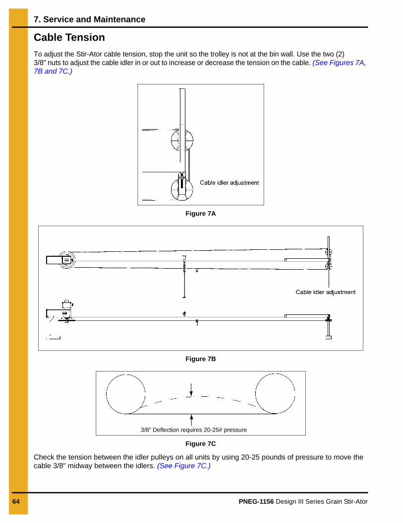
64 PNEG-1156 Design III Series Grain Stir-Ator
7. Service and Maintenance
Cable Tension
To adjust the Stir-Ator cable tension, stop the unit so the trolley is not at the bin wall. Use the two (2) 3/8" nuts to adjust the cable idler in or out to increase or decrease the tension on the cable. (See Figures 7A, 7B and 7C.)
Figure 7A
Figure 7B
Figure 7C
Check the tension between the idler pulleys on all units by using 20-25 pounds of pressure to move the cable 3/8" midway between the idlers. (See Figure 7C.)
3/8" Deflection requires 20-25# pressure

7. Service and Maintenance
PNEG-1156 Design III Series Grain Stir-Ator 65
Trolley Drive Link
Continuous stirring at any fixed distance from the center of the bin can be done by the use of the center trolley drive link. To use this feature, run the trolley to the desired location, unhook the link going through the drive sheave and hook the drive link to one of the hook slots above the sheave. (See Figure 7D.)
Figure 7D
This will prevent the trolley from moving in or out of the frame rails. To have continuous stirring at the bin wall, position the cable connector between the cable idler sheaves and hook the link in the hook slot. The unit will automatically re-hook itself if the link is dropped off the hook slots and resume driving the trolley in and out of the frame rails.
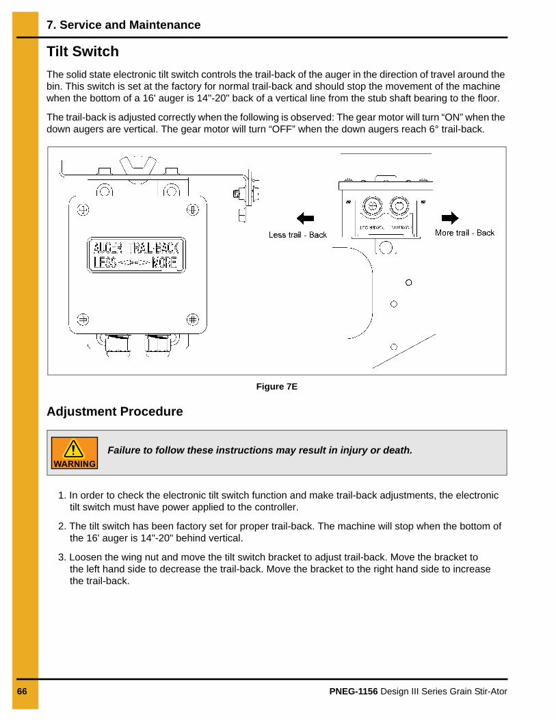
7. Service and Maintenance
66 PNEG-1156 Design III Series Grain Stir-Ator
Tilt Switch
The solid state electronic tilt switch controls the trail-back of the auger in the direction of travel around the bin. This switch is set at the factory for normal trail-back and should stop the movement of the machine when the bottom of a 16' auger is 14"-20" back of a vertical line from the stub shaft bearing to the floor.
The trail-back is adjusted correctly when the following is observed: The gear motor will turn “ON” when the down augers are vertical. The gear motor will turn “OFF” when the down augers reach 6° trail-back.
Figure 7E
Adjustment Procedure
1. In order to check the electronic tilt switch function and make trail-back adjustments, the electronic tilt switch must have power applied to the controller.
2. The tilt switch has been factory set for proper trail-back. The machine will stop when the bottom of the 16' auger is 14"-20" behind vertical.
3. Loosen the wing nut and move the tilt switch bracket to adjust trail-back. Move the bracket to the left hand side to decrease the trail-back. Move the bracket to the right hand side to increase the trail-back.
Failure to follow these instructions may result in injury or death.

7. Service and Maintenance
PNEG-1156 Design III Series Grain Stir-Ator 67
Safety Shut Off Switch
The automatic shut off chain is for safety. It is designed to shut off the electrical power to the unit should the trolley or swivel unit bind up, preventing normal travel of the Stir-Ator. To properly attach, hook the chain end with the open loop to the “S” hook welded to the suspension bar. Hook the other end of the chain onto the “S” hook in the switch box handle.
Use the “S” hook on the end of the shut off chain to hook any excess chain slack back on to the chain itself. This allows the length of the shut off chain to be adjusted at the switch box.
Figure 7F
With the unit running, there should only be enough slack in the chain so that the switch box handle is not pulled down during normal operation. Too much slack in the chain will fail to shut the unit off if there is a problem and could get caught in the machine itself as the Stir-Ator passes under the shut off chain. Secure the shut off chain and the electrical wire above the Stir-Ator with the provided shut off support chain(s). (See Figure 7F.)
Design III Stir-Ator
The electric cord must have more slack than the shut off chain so in the event of a shut off, the electric cord is not ripped from the switch box. This could cause electrical shock or bodily injury.

68 PNEG-1156 Design III Series Grain Stir-Ator
8. Troubleshooting
Design III Stir-Ator Troubleshooting
Problem Probable Cause/Potential Solution
1. Auger motor(s) and gear motor do not run.
1. Main power is not ON.
2. Contactor in swivel box is bad. (Replace.)
3. Contacts in contactor are dirty or burned. (Clean or replace.)
4. Swivel straps are loose or broken. (Replace strap or clip.)
5. There is a broken, loose or shorted wire. (Call electrician.)
6. Stir-Guard solid state module is bad. (Replace.)
7. Junction box on trolley is improperly wired. (New installation only - See Wiring Diagram on Page 70.)
8. Electrical swivel shorted or loose connection.
2. Gear motor runs but not the auger motor(s).
1. Auger motor overload tripped. (Push reset button on motor.)
2. Augers is stuck in grain. (See Start-Up Procedures on Page 43.)
3. Motor is burned out. (Replace.)
4. There is improper wiring at trolley junction box. (New installation only.)
5. Motor HP may not be adequate for length of auger.
6. Fuse is blown. (Replace.)
3. Auger motors run but gear motor does not.
1. Gear motor fuse is blown. (Replace.)
2. Low voltage or wired for 115 volts. (Check trolley junction box for proper wiring.)
3. Gear motor is burned out. (Replace.)
4. Gear motor case transmission is a problem. (Repair or replace.)
5. Drive chain is off sprocket.
6. Augers trailed back and mercury switch shut gear motor off. (Normal - See Problems #6 on Page 69.)
7. Tilt switch not adjusted properly.
8. Gear motor and tilt switch not wired properly at trolley junction box.
9. Auger will not advance through grain. (See Problems #6 on Page 69.)
10. Gear motor overload tripped - overload will reset automatically when cool.Check for excessive drag.
4. Unit has been tripped off by safety chain.
1. Chain is adjusted too tight. (See Shut Off Chain Adjustments on Page 38.)
2. Switch box handle moves too freely. (Replace box or hook common door spring from handle to bin roof, being sure it is not too tight to prevent safety shut off from working properly.)
3. Augers are too long and touch floor.
4. There are foreign object in corn stops.
5. Trolley is binding on frame rails.
6. Cable connector is installed backwards not going around idler pulleys.
7. Check correct length unit for bin size.
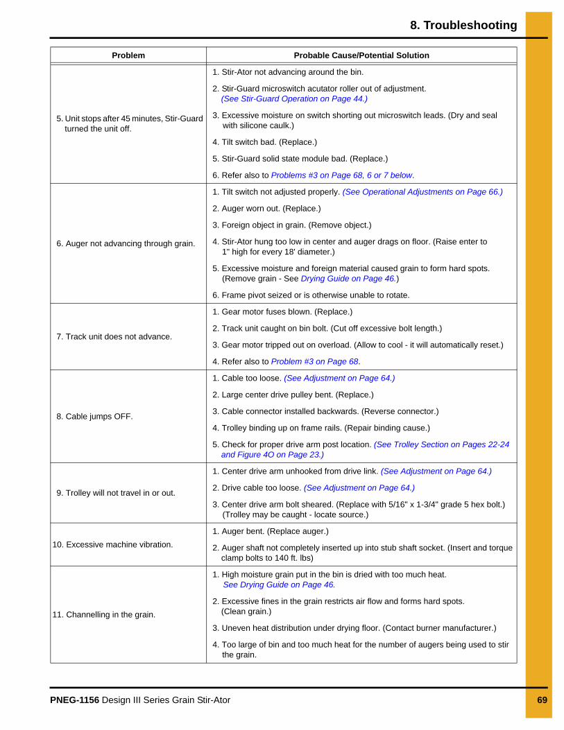
8. Troubleshooting
PNEG-1156 Design III Series Grain Stir-Ator 69
5. Unit stops after 45 minutes, Stir-Guard turned the unit off.
1. Stir-Ator not advancing around the bin.
2. Stir-Guard microswitch acutator roller out of adjustment. (See Stir-Guard Operation on Page 44.)
3. Excessive moisture on switch shorting out microswitch leads. (Dry and seal with silicone caulk.)
4. Tilt switch bad. (Replace.)
5. Stir-Guard solid state module bad. (Replace.)
6. Refer also to Problems #3 on Page 68, 6 or 7 below.
6. Auger not advancing through grain.
1. Tilt switch not adjusted properly. (See Operational Adjustments on Page 66.)
2. Auger worn out. (Replace.)
3. Foreign object in grain. (Remove object.)
4. Stir-Ator hung too low in center and auger drags on floor. (Raise enter to 1" high for every 18' diameter.)
5. Excessive moisture and foreign material caused grain to form hard spots. (Remove grain - See Drying Guide on Page 46.)
6. Frame pivot seized or is otherwise unable to rotate.
7. Track unit does not advance.
1. Gear motor fuses blown. (Replace.)
2. Track unit caught on bin bolt. (Cut off excessive bolt length.)
3. Gear motor tripped out on overload. (Allow to cool - it will automatically reset.)
4. Refer also to Problem #3 on Page 68.
8. Cable jumps OFF.
1. Cable too loose. (See Adjustment on Page 64.)
2. Large center drive pulley bent. (Replace.)
3. Cable connector installed backwards. (Reverse connector.)
4. Trolley binding up on frame rails. (Repair binding cause.)
5. Check for proper drive arm post location. (See Trolley Section on Pages 22-24 and Figure 4O on Page 23.)
9. Trolley will not travel in or out.
1. Center drive arm unhooked from drive link. (See Adjustment on Page 64.)
2. Drive cable too loose. (See Adjustment on Page 64.)
3. Center drive arm bolt sheared. (Replace with 5/16" x 1-3/4" grade 5 hex bolt.) (Trolley may be caught - locate source.)
10. Excessive machine vibration.
1. Auger bent. (Replace auger.)
2. Auger shaft not completely inserted up into stub shaft socket. (Insert and torque clamp bolts to 140 ft. lbs)
11. Channelling in the grain.
1. High moisture grain put in the bin is dried with too much heat.See Drying Guide on Page 46.
2. Excessive fines in the grain restricts air flow and forms hard spots. (Clean grain.)
3. Uneven heat distribution under drying floor. (Contact burner manufacturer.)
4. Too large of bin and too much heat for the number of augers being used to stir the grain.
Problem Probable Cause/Potential Solution
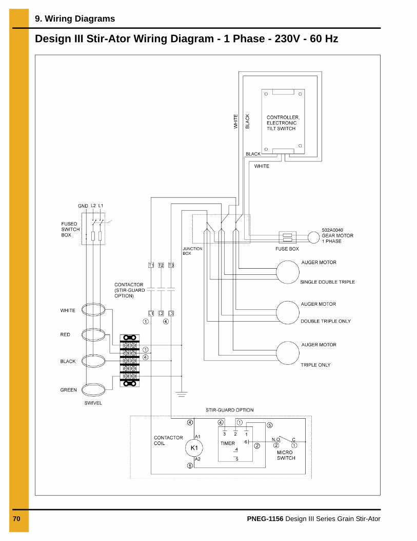
70 PNEG-1156 Design III Series Grain Stir-Ator
9. Wiring Diagrams
Design III Stir-Ator Wiring Diagram - 1 Phase - 230V - 60 Hz

PNEG-1156 Design III Series Grain Stir-Ator 71
10. Warranty
GSI Group, LLC Limited WarrantyThe GSI Group, LLC (“GSI”) warrants products which it manufactures to be free of defects in materials and workmanship under normal usage and conditions for a period of 12 months after sale to the original end-user or if a foreign sale, 14 months from arrival at port of discharge, whichever is earlier. The end-user’s sole remedy (and GSI’s only obligation) is to repair or replace, at GSI’s option and expense, products that in GSI’s judgment, contain a material defect in materials or workmanship. Expenses incurred by or on behalf of the end-user without prior written authorization from the GSI Warranty Group shall be the sole responsibility of the end-user.
Warranty Extensions:The Limited Warranty period is extended for the following products:
GSI further warrants that the portable and tower dryer frame and basket, excluding all auger and auger drive components, shall be free from defects in materials for a period of time beginning on the twelfth (12th) month from the date of purchase and continuing until the sixtieth (60th) month from the date of purchase (extended warranty period). During the extended warranty period, GSI will replace the frame or basket components that prove to be defective under normal conditions of use without charge, excluding the labor, transportation, and/or shipping costs incurred in the performance of this extended warranty.
Conditions and Limitations:THERE ARE NO WARRANTIES THAT EXTEND BEYOND THE LIMITED WARRANTY DESCRIPTION SET FORTH ABOVE. SPECIFICALLY, GSI MAKES NO FURTHER WARRANTY OF ANY KIND, EXPRESS OR IMPLIED, INCLUDING, WITHOUT LIMITATION, WARRANTIES OF MERCHANTABILITY OR FITNESS FOR A PARTICULAR PURPOSE OR USE IN CONNECTION WITH: (I) PRODUCT MANUFACTURED OR SOLD BY GSI OR (II) ANY ADVICE, INSTRUCTION, RECOMMENDATION OR SUGGESTION PROVIDED BY AN AGENT, REPRESENTATIVE OR EMPLOYEE OF GSI REGARDING OR RELATED TO THE CONFIGURATION, INSTALLATION, LAYOUT, SUITABILITY FOR A PARTICULAR PURPOSE, OR DESIGN OF SUCH PRODUCTS.
GSI shall not be liable for any direct, indirect, incidental or consequential damages, including, without limitation, loss of anticipated profits or benefits. The sole and exclusive remedy is set forth in the Limited Warranty, which shall not exceed the amount paid for the product purchased. This warranty is not transferable and applies only to the original end-user. GSI shall have no obligation or responsibility for any representations or warranties made by or on behalf of any dealer, agent or distributor.
GSI assumes no responsibility for claims resulting from construction defects or unauthorized modifications to products which it manufactured. Modifications to products not specifically delineated in the manual accompanying the equipment at initial sale will void the Limited Warranty.
This Limited Warranty shall not extend to products or parts which have been damaged by negligent use, misuse, alteration, accident or which have been improperly/inadequately maintained. This Limited Warranty extends solely to products manufactured by GSI.
Prior to installation, the end-user has the responsibility to comply with federal, state and local codes which apply to the location and installation of products manufactured or sold by GSI.
Product Warranty Period
AP Fans and Flooring
Performer Series Direct Drive Fan Motor 3 Years * Warranty prorated from list price:
0 to 3 years - no cost to end-user
3 to 5 years - end-user pays 25%
5 to 7 years - end-user pays 50%
7 to 10 years - end-user pays 75%
** Warranty prorated from list price:
0 to 3 years - no cost to end-user
3 to 5 years - end-user pays 50%
† Motors, burner components and moving parts not included. Portable dryer screens included. Tower dryer screens not included.
All Fiberglass Housings Lifetime
All Fiberglass Propellers Lifetime
AP and Cumberland Flex-Flo/Pan Feeding System Motors 2 Years
Cumberland Feeding/Watering Systems
Feeder System Pan Assemblies 5 Years **
Feed Tubes (1-3/4" and 2.00") 10 Years *
Centerless Augers 10 Years *
Watering Nipples 10 Years *
Grain Systems Grain Bin Structural Design 5 Years
Grain SystemsFarm FansZimmerman
Portable and Tower Dryers 2 Years
Portable and Tower Dryer Frames and Internal Infrastructure †
5 Years
9101239_1_CR_rev8.DOC (revised January 2014)

This equipment shall be installed in accordance with the current installation codes and applicable
regulations, which should be carefully followed in all cases. Authorities having jurisdiction should be
consulted before installations are made.
1004 E. Illinois St. Assumption, IL 62510-0020
Phone: 1-217-226-4421 Fax: 1-217-226-4420
www.gsiag.com
Copyright © 2016 by The GSI Group, LLCPrinted in the USA CN-320834
GSI is a worldwide brand of AGCO Corporation.