Embed Size (px)
Citation preview

Moisture Controller
Installation Manual
PNEG-1405
Version: 2.1
Date: 09-24-20PNEG-1405

2 PNEG-1405 Moisture Controller
All information, illustrations, photos and specifications in this manual are based on the latestinformation available at the time of publication. The right is reserved to make changes at anytime without notice.
Table of Contents
PNEG-1405 Moisture Controller 3
ContentsChapter 1 Safety .....................................................................................................................................................4
Safety Guidelines .................................................................................................................................. 4Safety Instructions ................................................................................................................................. 5
Chapter 2 Component Installation .......................................................................................................................7
Chapter 3 Electrical Connections .......................................................................................................................12
Chapter 4 Warranty ..............................................................................................................................................17
4 PNEG-1405 Moisture Controller
1. Safety
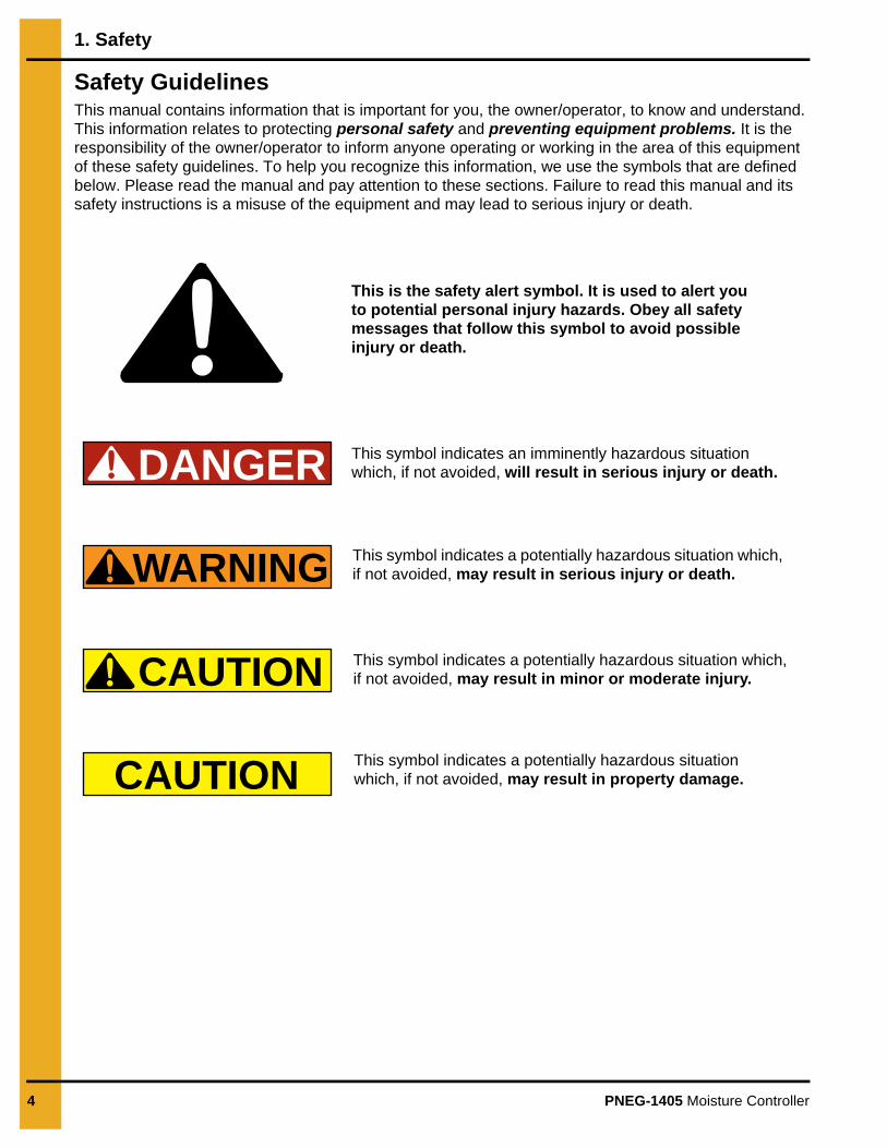
Safety GuidelinesThis manual contains information that is important for you, the owner/operator, to know and understand. This information relates to protecting personal safety and preventing equipment problems. It is the responsibility of the owner/operator to inform anyone operating or working in the area of this equipment of these safety guidelines. To help you recognize this information, we use the symbols that are defined below. Please read the manual and pay attention to these sections. Failure to read this manual and its safety instructions is a misuse of the equipment and may lead to serious injury or death.
DANGER
WARNING
CAUTION
CAUTION
This is the safety alert symbol. It is used to alert you to potential personal injury hazards. Obey all safety messages that follow this symbol to avoid possible injury or death.
This symbol indicates a potentially hazardous situation which, if not avoided, may result in serious injury or death.
This symbol indicates a potentially hazardous situation which, if not avoided, may result in minor or moderate injury.
This symbol indicates a potentially hazardous situation which, if not avoided, may result in property damage.
This symbol indicates an imminently hazardous situation which, if not avoided, will result in serious injury or death.

1. Safety
PNEG-1405 Moisture Controller 5
Safety Instructions
Our foremost concern is your safety and the safety of others associated with this equipment. We want to keep you as a customer. This manual is to help you understand safe operating procedures and some problems that may be encountered by the operator and other personnel.
As owner and/or operator, it is your responsibility to know what requirements, hazards and precautions exist and to inform all personnel associated with the equipment or in the area. Safety precautions may be required from the personnel. Avoid any alterations to the equipment. Such alterations may produce a very dangerous situation where SERIOUS INJURY or DEATH may occur.
This equipment shall be installed in accordance with the current installation codes and applicable regulations, which should be carefully followed in all cases. Authorities having jurisdiction should be consulted before installations are made.
Follow Safety Instructions
Carefully read all safety messages in this manual and safety signs on your machine. Keep signs in good condition. Replace missing or damaged safety signs. Be sure new equipment components and repair parts include the current safety signs. Replacement safety signs are available from the manufacturer.
Learn how to operate the machine and how to use controls properly. Do not let anyone operate without instruction.
Keep your machinery in proper working condition. Unauthorized modifications to the machine may impair the function and/or safety and affect machine life.
If you do not understand any part of this manual or need assistance, contact your dealer.
Read and Understand Manual
Prepare for Emergencies
Be prepared if fire starts.
Keep a first aid kit and fire extinguisher handy.
Keep emergency numbers for doctors, ambulance service, hospital and fire department near your telephone.
Keep Emergency Equipment Quickly Accessible
1. Safety
6 PNEG-1405 Moisture Controller
Wear Protective Clothing
Wear close-fitting clothing and safety equipment appropriate to the job.
Remove all jewelry.
Tie long hair up and back.
Wear safety glasses at all times to protect eyes from debris.
Wear gloves to protect your hands from sharp edges on plastic or steel parts.
Wear steel toe boots to help protect your feet from falling debris. Tuck in any loose or dangling shoestrings.
A respirator may be needed to prevent breathing potentially toxic fumes and dust.
Wear a hard hat to help protect your head.
Wear appropriate fall protection equipment when working at elevations greater than six feet (6').
Eye Protection
Gloves
Steel-Toed Boots
Respirator
Hard Hat
Fall Protection

PNEG-1405 Moisture Controller 7
2. Component Installation
Location for the Moisture control box second and third leg back from dryer control box.
Figure 2A
Moisture control box leg channel. (D01-1656)
Figure 2B
Moisture control box leg channels installed.
Figure 2C
2. Component Installation
8 PNEG-1405 Moisture Controller
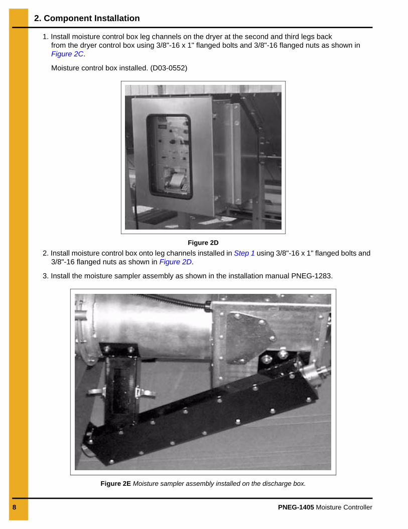
1. Install moisture control box leg channels on the dryer at the second and third legs back from the dryer control box using 3/8"-16 x 1" flanged bolts and 3/8"-16 flanged nuts as shown in Figure 2C.
Moisture control box installed. (D03-0552)
Figure 2D
2. Install moisture control box onto leg channels installed in Step 1 using 3/8"-16 x 1" flanged bolts and 3/8"-16 flanged nuts as shown in Figure 2D.
3. Install the moisture sampler assembly as shown in the installation manual PNEG-1283.
Figure 2E Moisture sampler assembly installed on the discharge box.
2. Component Installation
PNEG-1405 Moisture Controller 9
Figure 2F Moisture Sensor (602E020) Figure 2G
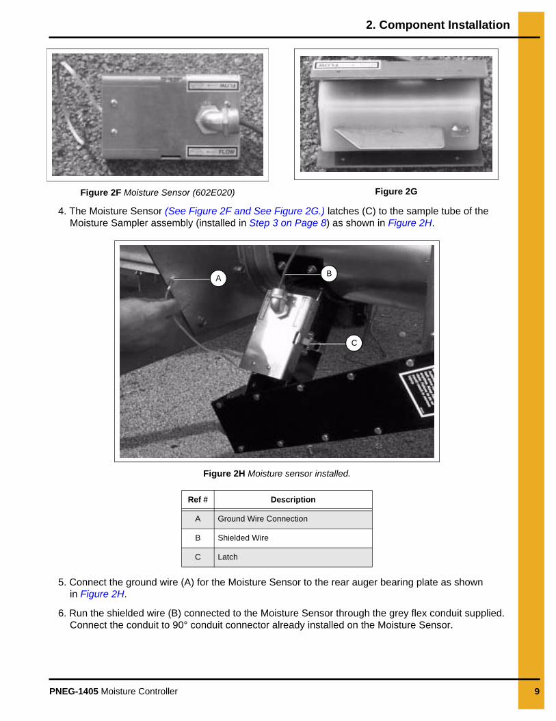
4. The Moisture Sensor (See Figure 2F and See Figure 2G.) latches (C) to the sample tube of the Moisture Sampler assembly (installed in Step 3 on Page 8) as shown in Figure 2H.
Figure 2H Moisture sensor installed.
5. Connect the ground wire (A) for the Moisture Sensor to the rear auger bearing plate as shown in Figure 2H.
6. Run the shielded wire (B) connected to the Moisture Sensor through the grey flex conduit supplied. Connect the conduit to 90° conduit connector already installed on the Moisture Sensor.
Ref # Description
A Ground Wire Connection
B Shielded Wire
C Latch
AB
C
2. Component Installation
10 PNEG-1405 Moisture Controller
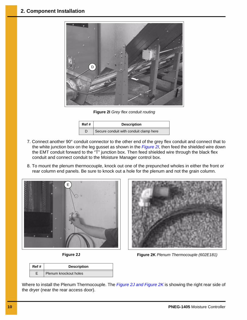
Figure 2I Grey flex conduit routing
7. Connect another 90° conduit connector to the other end of the grey flex conduit and connect that to the white junction box on the leg gusset as shown in the Figure 2I, then feed the shielded wire down the EMT conduit forward to the “T” junction box. Then feed shielded wire through the black flex conduit and connect conduit to the Moisture Manager control box.
8. To mount the plenum thermocouple, knock out one of the prepunched wholes in either the front or rear column end panels. Be sure to knock out a hole for the plenum and not the grain column.
Figure 2J Figure 2K Plenum Thermocouple (602E181)
Where to install the Plenum Thermocouple. The Figure 2J and Figure 2K is showing the right rear side of the dryer (near the rear access door).
Ref # Description
D Secure conduit with conduit clamp here
D
Ref # Description
E Plenum knockout holes
E
2. Component Installation
PNEG-1405 Moisture Controller 11
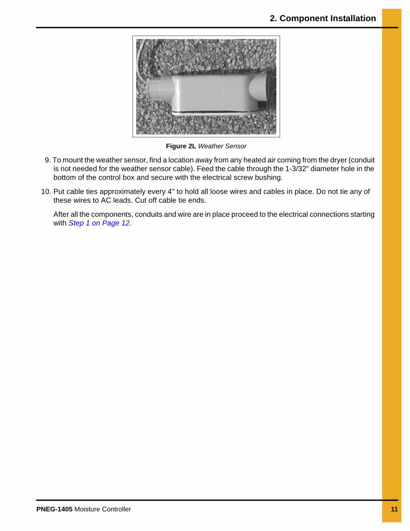
Figure 2L Weather Sensor
9. To mount the weather sensor, find a location away from any heated air coming from the dryer (conduit is not needed for the weather sensor cable). Feed the cable through the 1-3/32" diameter hole in the bottom of the control box and secure with the electrical screw bushing.
10. Put cable ties approximately every 4'' to hold all loose wires and cables in place. Do not tie any of these wires to AC leads. Cut off cable tie ends.
After all the components, conduits and wire are in place proceed to the electrical connections starting with Step 1 on Page 12.
12 PNEG-1405 Moisture Controller
3. Electrical Connections
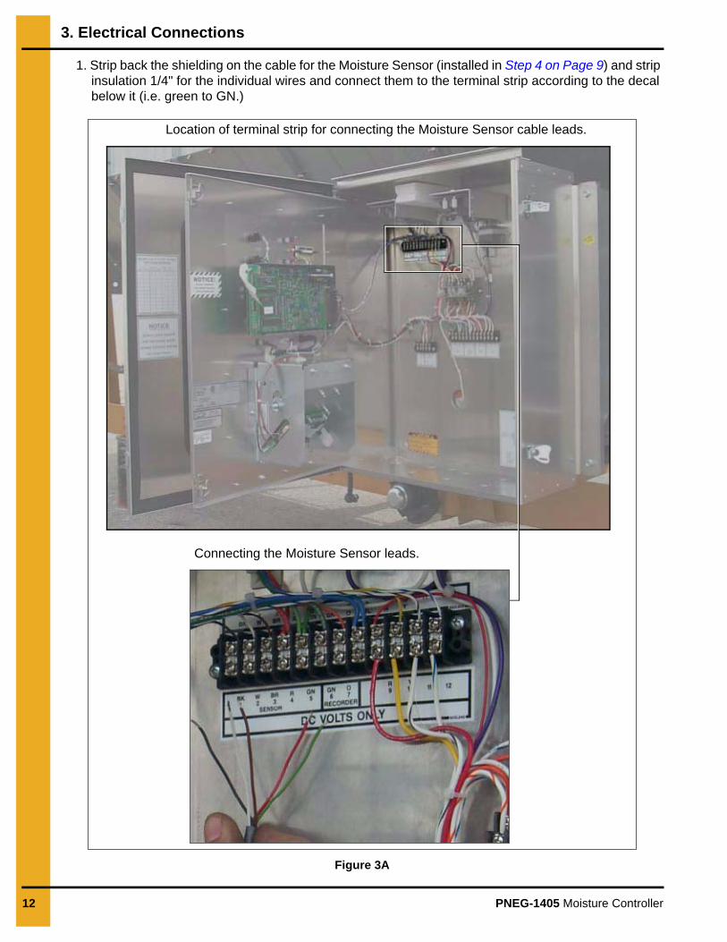
1. Strip back the shielding on the cable for the Moisture Sensor (installed in Step 4 on Page 9) and strip insulation 1/4" for the individual wires and connect them to the terminal strip according to the decal below it (i.e. green to GN.)
Figure 3A
Location of terminal strip for connecting the Moisture Sensor cable leads.
Connecting the Moisture Sensor leads.
3. Electrical Connections
PNEG-1405 Moisture Controller 13
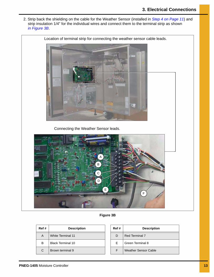
2. Strip back the shielding on the cable for the Weather Sensor (installed in Step 4 on Page 11) and strip insulation 1/4" for the individual wires and connect them to the terminal strip as shown in Figure 3B.
Figure 3B
Ref # Description Ref # Description
A White Terminal 11 D Red Terminal 7
B Black Terminal 10 E Green Terminal 8
C Brown terminal 9 F Weather Sensor Cable
Location of terminal strip for connecting the weather sensor cable leads.
Connecting the Weather Sensor leads.
A
B
D
EF
C
3. Electrical Connections
14 PNEG-1405 Moisture Controller
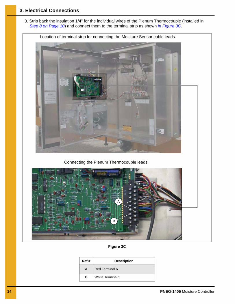
3. Strip back the insulation 1/4" for the individual wires of the Plenum Thermocouple (installed in Step 8 on Page 10) and connect them to the terminal strip as shown in Figure 3C.
Figure 3C
Ref # Description
A Red Terminal 6
B White Terminal 5
Location of terminal strip for connecting the Moisture Sensor cable leads.
Connecting the Plenum Thermocouple leads.
A
B
3. Electrical Connections
PNEG-1405 Moisture Controller 15
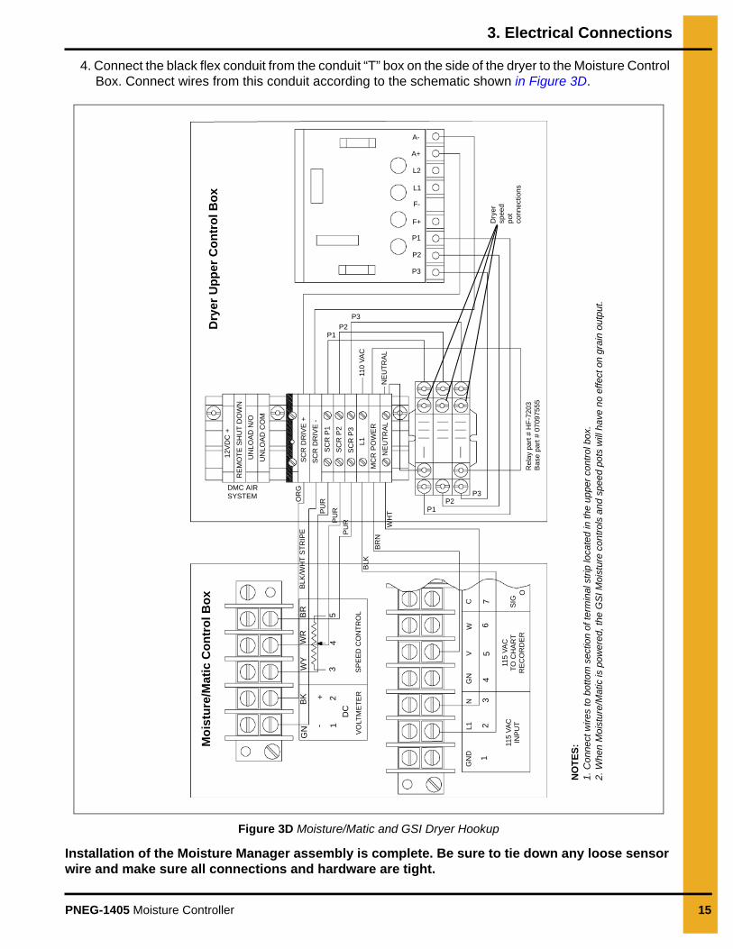
4. Connect the black flex conduit from the conduit “T” box on the side of the dryer to the Moisture Control Box. Connect wires from this conduit according to the schematic shown in Figure 3D.
Figure 3D Moisture/Matic and GSI Dryer Hookup
Installation of the Moisture Manager assembly is complete. Be sure to tie down any loose sensor wire and make sure all connections and hardware are tight.
Mo
istu
re/M
atic
Co
ntr
ol B
ox
GN
BK
-+
12
DC
VO
LTM
ET
ER
WY
WR
BR
34
5
SP
EE
D C
ON
TR
OL
GN
DL
1N
GN
VW
C
12
34
56
7
115
VA
CIN
PU
T
115
VA
CT
O C
HA
RT
RE
CO
RD
ER
SIG
O
NO
TE
S:
1. C
onne
ct w
ires
to b
otto
m s
ectio
n of
term
inal
str
ip lo
cate
d in
the
uppe
r co
ntro
l bo
x.2.
Whe
n M
oist
ure/
Mat
ic is
pow
ere
d, th
e G
SI M
oist
ure
con
trol
s an
d s
pee
d po
ts w
ill h
ave
no e
ffect
on
grai
n ou
tput
.
BLK
/WH
T S
TR
IPE
DMC AIRSYSTEM O
RG
PU
R
PU
R
PU
R
BLK
BR
N
WH
T P1P2
P3
12V
DC
+
RE
MO
TE
SH
UT
DO
WN
UN
LO
AD
N/O
UN
LO
AD
CO
M
SC
R D
RIV
E +
SC
R D
RIV
E -
SC
R P
1
SC
R P
2
SC
R P
3
L1
MC
R P
OW
ER
NE
UT
RA
L
P1P2
P3
110
VA
C
NE
UT
RA
L
Re
lay
part
# H
F-7
20
3B
ase
par
t # 0
709
755
5
Dry
ersp
eed
p
otco
nnec
tion
s
A-
A+
L2
L1
F-
F+
P1
P2
P3
Dry
er U
pp
er C
on
tro
l Bo
x

16 PNEG-1405 Moisture Controller
NOTES
Limited Warranty — N.A. Grain ProductsThe GSI Group, LLC. (“GSI”) warrants products which it manufactures, to be free of defects in materials and workmanshipunder normal usage and conditions for a period of 12 months from the date of shipment (or, if shipped by vessel, 14months from the date of arrival at the port of discharge). If, in GSI’s sole judgment, a product is found to have a defect inmaterials and/or workmanship, GSI will, at its own option and expense, repair or replace the product or refund thepurchase price. This Limited Warranty is subject to extension and other terms as set forth below.
Warranty Enhancements: The warranty period for the following products is enhanced as shown below and is inlieu of (and not in addition to) the above stated warranty period. (Warranty Period is from date of shipment.)
Product Warranty Period
Storage
Grain Bin Structural Design▪ Sidewall, roof, doors, platforms and walkarounds▪ Flooring (when installed using GSI specified floor support system for that floor)▪ Hopper tanks (BFT, GHT, NCHT, and FCHT)
5 Years
Conditioning
Dryer Structural Design – (Tower, Portable and TopDry)▪ Includes (frame, portable dryer screens, ladders, access doors and platforms) 5 Years
All other Dryer parts including:▪ Electrical (controls, sensors, switches and internal wiring) 2 Years
All Non-PTO Driven Centrifugal and Axial Fans 3 Years
Bullseye Controllers 2 Years
MaterialHandling
Bucket Elevators Structural Design 5 Years
Towers Structural Design 5 Years
Catwalks Structural Design 5 Years
Accessories (stairs, ladders and platforms) Structural Design 5 Years
Conditions and Limitations:THERE ARE NO WARRANTIES THAT EXTEND BEYOND THE LIMITED WARRANTY DESCRIPTION SET FORTHHEREIN; SPECIFICALLY, GSI DISCLAIMS ANY AND ALL OTHER WARRANTIES OF ANY KIND, EXPRESS ORIMPLIED, INCLUDING, WITHOUT LIMITATION, WARRANTIES OF MERCHANTABILITY OR FITNESS FOR APARTICULAR PURPOSE OR USE IN CONNECTION WITH: (I) ANY PRODUCT MANUFACTURED OR SOLD BY GSI,OR (II) ANY ADVICE, INSTRUCTION, RECOMMENDATION OR SUGGESTION PROVIDED BY AN AGENT,REPRESENTATIVE OR EMPLOYEE OF GSI REGARDING OR RELATED TO THE CONFIGURATION, INSTALLATION,LAYOUT, SUITABILITY FOR A PARTICULAR PURPOSE, OR DESIGN OF SUCH PRODUCTS.
The sole and exclusive remedy for any claimant is set forth in this Limited Warranty and shall not exceed the amount paidfor the product purchased. This Warranty only covers the value of the warranted parts and equipment, and does not coverlabor charges for removing or installing defective parts, shipping charges with respect to such parts, any applicable salesor other taxes, or any other charges or expenses not specified in this Warranty. GSI shall not be liable for any other direct,indirect, incidental or consequential damages, including, without limitation, loss of anticipated profits or benefits. Expensesincurred by or on behalf of a claimant without prior written authorization from the GSI warranty department shall not bereimbursed. This warranty is not transferable and applies only to the original end-user. GSI shall have no obligation orresponsibility for any representations or warranties made by or on behalf of any dealer, agent or distributor. Prior toinstallation, the end-user bears all responsibility to comply with federal, state and local codes which apply to the locationand installation of the products.
This Limited Warranty extends solely to products sold by GSI and does not cover any parts, components or materials used in conjunction with theproduct, that are not sold by GSI. GSI assumes no responsibility for claims resulting from construction defects, unauthorized modifications,corrosion or other cosmetic issues caused by storage, application or environmental conditions. Modifications to products not specificallydelineated in the manual accompanying the product at initial sale will void all warranties. This Limited Warranty shall not extend to products orparts which have been damaged by negligent use, misuse, alteration, accident or which have been improperly/inadequately maintained.
Notice Procedure:In order to make a valid warranty claim a written notice of the claim must be submitted, using the RMA form, within 60 days of discovery of awarrantable nonconformance. The RMA form is found on the OneGSI portal.Service Parts:GSI warrants, subject to all other conditions described in this Warranty, Service Parts which it manufactures for a period of 12 months from thedate of purchase unless specified in Enhancements above.(Limited Warranty - N.A. Grain Products_ revised 01 October 2020)

This equipment shall be installed in accordance with the current installation codes and applicable
regulations, which should be carefully followed in all cases. Authorities having jurisdiction should be
consulted before installations are made.
GSI Group 1004 E. Illinois St.
Assumption, IL 62510-0020 Phone: 1-217-226-4421
Fax: 1-217-226-4420 www.gsiag.com
Copyright © 2016 by The GSI Group, LLCPrinted in the USA CN-314486
GSI is a worldwide brand of AGCO Corporation.