Embed Size (px)
Citation preview
PNEG-119
Inline Centrifugal Fan Installation and Operation
Model #:
Owner’s Manual
PNEG-119Date: 03-11-09
2 PNEG-119 Inline Centrifugal Fan
Fan Check List
1. All wire connections
2. Tip clearance on blade
3. Fan blade torqued to torque specs
4. Grill guard in place and tight
5. Fuse in place, extra fuse provided
6. Motor rotation correct
7. Contactor engages properly
8. Running amperage
9. Vibration
10. All fasteners tight
11. Indicator light
12. All decals and serial number tag
13. Aesthetic appearance
14. Manual
Tester Signature: ___________________________________________
Date: ____________________________________
Record in the space provided below the Model # and Serial # of this product. These numbers are found on the Model and Serial Tags located on the outside of the unit.
Model #: ___________________________________________
Serial #: ___________________________________________
Keep these numbers for future reference.
Table of Contents
PNEG-119 Inline Centrifugal Fan 3
ContentsChapter 1 Safety .................................................................................................................................................. 4
Safety Guidelines ............................................................................................................................... 4Safety Instructions .............................................................................................................................. 5
Chapter 2 Safety Alert Decals ............................................................................................................................ 7
Chapter 3 Installation Instructions .................................................................................................................... 9Fan Pad Location ............................................................................................................................... 9Check List before Installing the Fan ................................................................................................... 9Installation ........................................................................................................................................ 10
Chapter 4 Fan Specifications ........................................................................................................................... 11
Chapter 5 Fan Installation ................................................................................................................................ 13Previously Installed Units ................................................................................................................. 13Machine to Earth Ground ................................................................................................................. 13Proper Installation of the Ground Rod .............................................................................................. 14
Chapter 6 Fan Operation .................................................................................................................................. 15Start-up ............................................................................................................................................ 15Maintaining Grain Quality ................................................................................................................. 15Grain Storage ................................................................................................................................... 15
Chapter 7 Fan Service ...................................................................................................................................... 17Relubrication Intervals (Motors with Regreasing Capability) ............................................................ 17Lubricant .......................................................................................................................................... 17Procedure ......................................................................................................................................... 17
Chapter 8 Troubleshooting .............................................................................................................................. 18
Chapter 9 Parts List .......................................................................................................................................... 1918"-28" Inline Parts .......................................................................................................................... 19
Chapter 10 Wiring Diagrams ............................................................................................................................ 201 Phase Schematic ........................................................................................................................ 203 HP 1 Phase Wiring Diagram and Parts ....................................................................................... 213, 7, 10 and 15 HP 1 Phase Wiring Diagrams and Parts ............................................................... 223 Phase 230 Volt Schematic .......................................................................................................... 253, 7, 10 and 15 HP 3 Phase 230 Volt Wiring Diagrams and Parts ................................................. 263 Phase 460 Volt Schematic .......................................................................................................... 293, 7, 10 and 15 HP 3 Phase 460 Volt Wiring Diagrams and Parts ................................................. 303 Phase 575 Volt Schematic .......................................................................................................... 333, 7, 10 and 15 HP 3 Phase 575 Volt Wiring Diagrams and Parts ................................................. 34
Chapter 11 Warranty ......................................................................................................................................... 37
4 PNEG-119 Inline Centrifugal Fan
1. Safety
Safety Guidelines
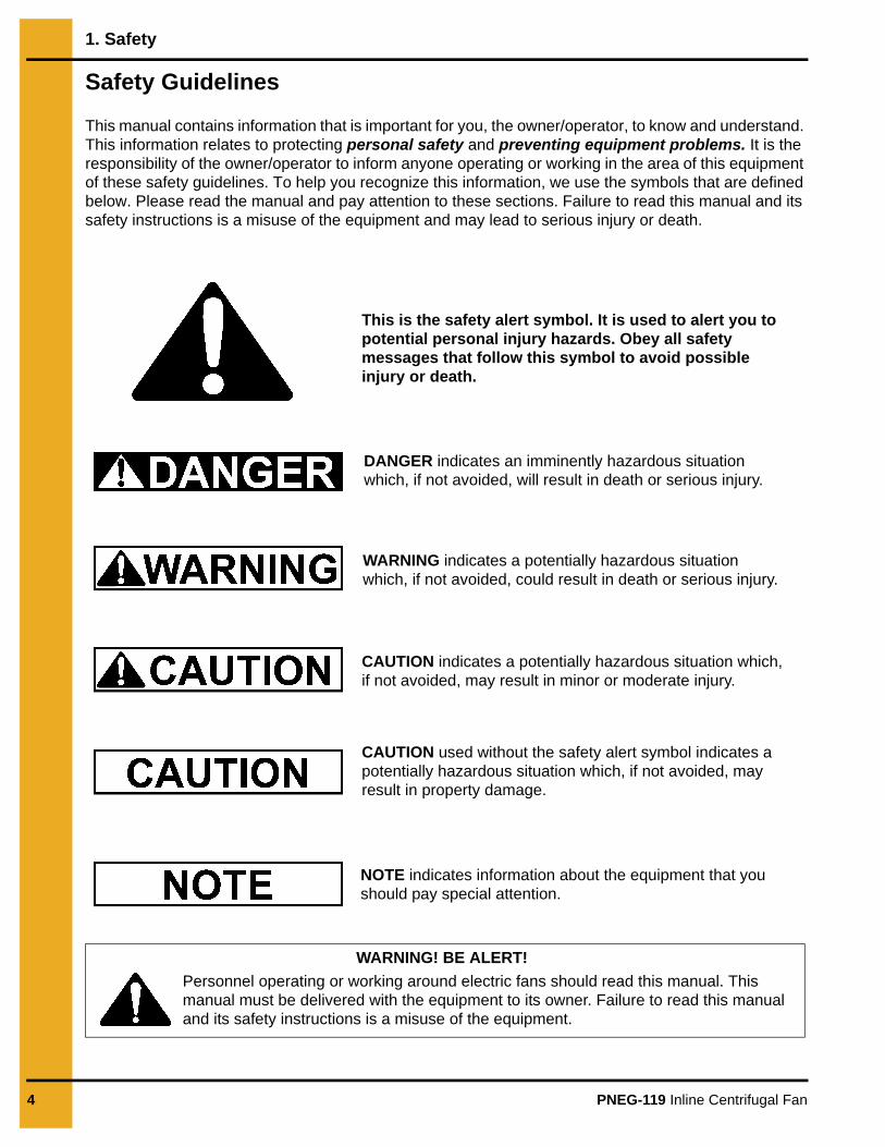
This manual contains information that is important for you, the owner/operator, to know and understand. This information relates to protecting personal safety and preventing equipment problems. It is the responsibility of the owner/operator to inform anyone operating or working in the area of this equipment of these safety guidelines. To help you recognize this information, we use the symbols that are defined below. Please read the manual and pay attention to these sections. Failure to read this manual and its safety instructions is a misuse of the equipment and may lead to serious injury or death.
This is the safety alert symbol. It is used to alert you to potential personal injury hazards. Obey all safety messages that follow this symbol to avoid possible injury or death.
WARNING indicates a potentially hazardous situation which, if not avoided, could result in death or serious injury.
CAUTION indicates a potentially hazardous situation which, if not avoided, may result in minor or moderate injury.
CAUTION used without the safety alert symbol indicates a potentially hazardous situation which, if not avoided, may result in property damage.
NOTE indicates information about the equipment that you should pay special attention.
DANGER indicates an imminently hazardous situation which, if not avoided, will result in death or serious injury.
Personnel operating or working around electric fans should read this manual. This manual must be delivered with the equipment to its owner. Failure to read this manual and its safety instructions is a misuse of the equipment.
WARNING! BE ALERT!
1. Safety
PNEG-119 Inline Centrifugal Fan 5
Fan OperationThank you for choosing a GSI Group product. It is designed to give excellent performance and service for many years.This manual describes the operation of the Inline Fan. Many models are available to accommodate different types of grain conditioning.This product is intended for the use of conditioning grain only. Any other use is a misuse of the product. This product has sharp edges, which may cause serious injury. To avoid injury, handle sharp edges with caution and always use proper protective clothing and equipment.
Safety Instructions
Our foremost concern is your safety and the safety of others associated with this equipment. We want to keep you as a customer. This manual is to help you understand safe operating procedures and some problems which may be encountered by the operator and other personnel.As owner and/or operator, it is your responsibility to know what requirements, hazards and precautions exist, and to inform all personnel associated with the equipment or in the area. Safety precautions may be required from the personnel. Avoid any alterations to the equipment. Such alterations may produce a very dangerous situation where SERIOUS INJURY or DEATH may occur.This equipment shall be installed in accordance with the current installation codes and applicable regulations which should be carefully followed in all cases. Authorities having jurisdiction should be consulted before installations are made.
Follow Safety Instructions
Carefully read all safety messages in this manual and safety signs on your machine. Keep signs in good condition. Replace missing or damaged safety signs. Be sure new equipment components and repair parts include the current safety signs. Replacement safety signs are available from the manufacturer.
Learn how to operate the machine and how to use controls properly. Do not let anyone operate without instruction.
Keep your machinery in proper working condition. Unauthorized modifications to the machine may impair the function and/or safety and affect machine life.
If you do not understand any part of this manual or need assistance, contact your dealer.
Read and Understand Manual
1. Safety
6 PNEG-119 Inline Centrifugal Fan
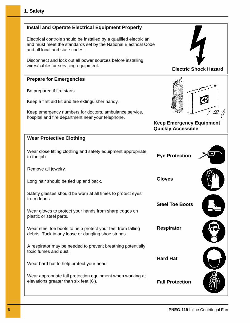
Install and Operate Electrical Equipment Properly
Electrical controls should be installed by a qualified electrician and must meet the standards set by the National Electrical Code and all local and state codes.
Disconnect and lock out all power sources before installing wires/cables or servicing equipment.
Electric Shock Hazard
Prepare for Emergencies
Be prepared if fire starts.
Keep a first aid kit and fire extinguisher handy.
Keep emergency numbers for doctors, ambulance service, hospital and fire department near your telephone.
Keep Emergency Equipment Quickly Accessible
Wear Protective Clothing
Wear close fitting clothing and safety equipment appropriateto the job.
Remove all jewelry.
Long hair should be tied up and back.
Safety glasses should be worn at all times to protect eyes from debris.
Wear gloves to protect your hands from sharp edges on plastic or steel parts.
Wear steel toe boots to help protect your feet from falling debris. Tuck in any loose or dangling shoe strings.
A respirator may be needed to prevent breathing potentially toxic fumes and dust.
Wear hard hat to help protect your head.
Wear appropriate fall protection equipment when working at elevations greater than six feet (6').
Eye Protection
Gloves
Steel Toe Boots
Respirator
Hard Hat
Fall Protection
PNEG-119 Inline Centrifugal Fan 7
2. Safety Alert Decals
The GSI Group recommends contacting the local power company, and having a representative survey the installation so the wiring is compatible with their system, and adequate power is supplied to the unit.
All precautions should be taken when lifting and/or moving. Use at least two men when moving the unit anywhere.
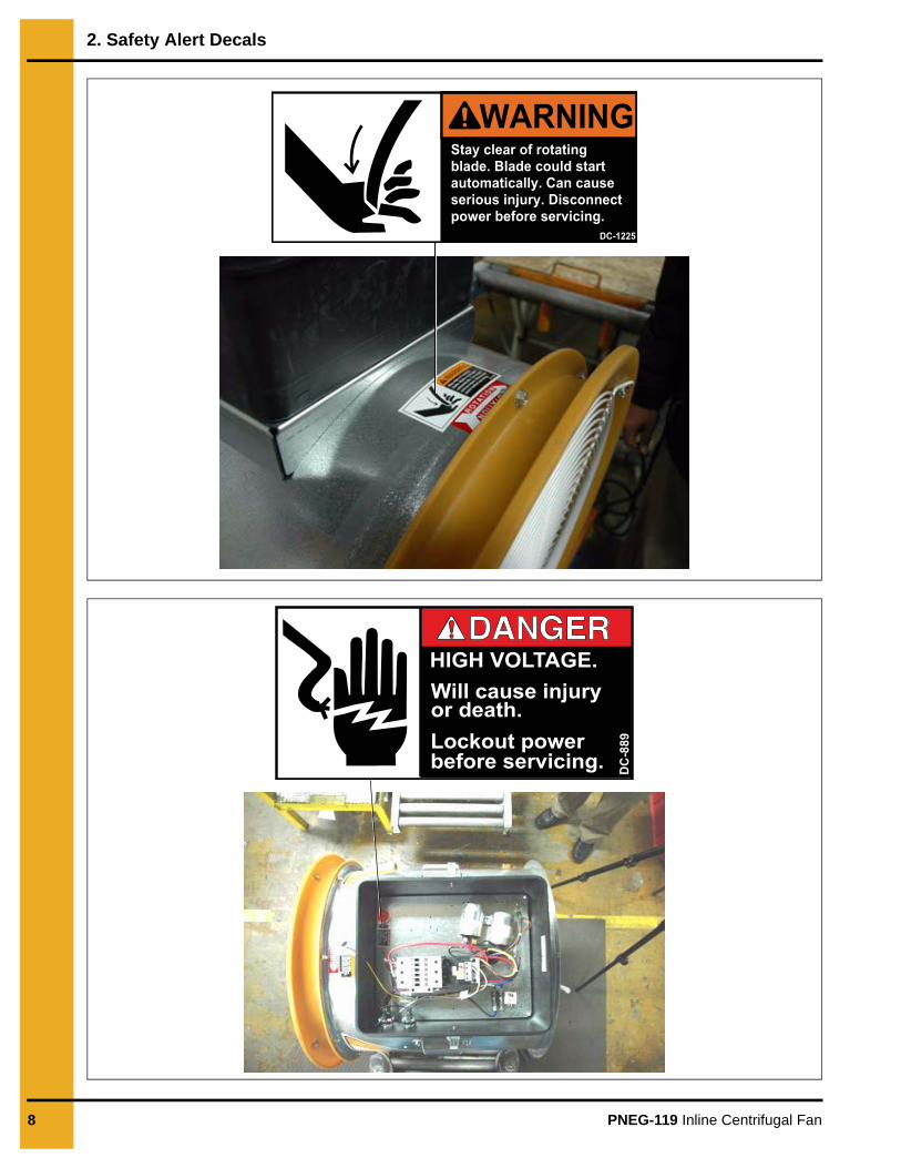
The safety pages that follow are to show you where you can find the safety decals. The photographs show exactly where the decals should be.
If a decal is damaged or missing, contact:
GSI Decals1004 E. Illinois St.Assumption, IL. 62510Phone: 217-226-4421
A free replacement will be sent to you.
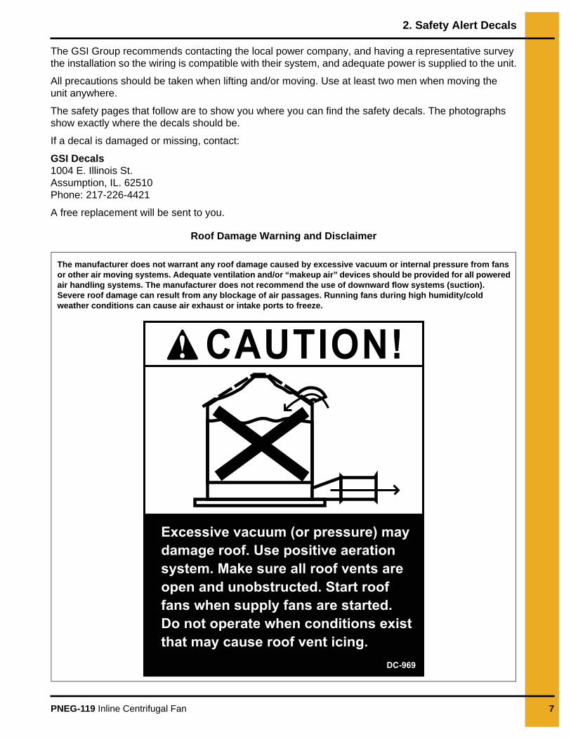
Roof Damage Warning and Disclaimer
CAUTION!
Excessive vacuum (or pressure) may damage roof. Use positive aeration system. Make sure all roof vents are open and unobstructed. Start roof fans when supply fans are started. Do not operate when conditions existthat may cause roof vent icing.
DC-969
The manufacturer does not warrant any roof damage caused by excessive vacuum or internal pressure from fans or other air moving systems. Adequate ventilation and/or “makeup air” devices should be provided for all powered air handling systems. The manufacturer does not recommend the use of downward flow systems (suction). Severe roof damage can result from any blockage of air passages. Running fans during high humidity/cold weather conditions can cause air exhaust or intake ports to freeze.
2. Safety Alert Decals
8 PNEG-119 Inline Centrifugal Fan
Stay clear of rotatingblade. Blade could startautomatically. Can causeserious injury. Disconnectpower before servicing.
DC-1225
WARNING
PNEG-119 Inline Centrifugal Fan 9
3. Installation Instructions
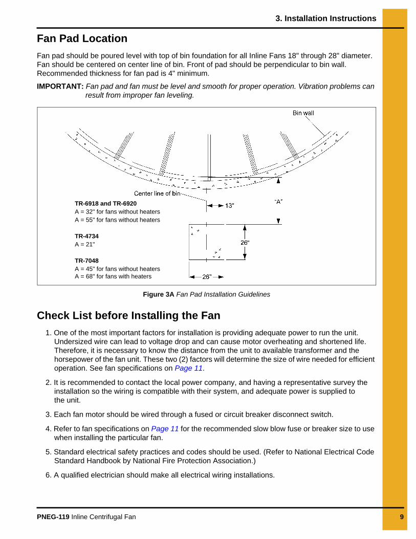
Fan Pad LocationFan pad should be poured level with top of bin foundation for all Inline Fans 18" through 28" diameter. Fan should be centered on center line of bin. Front of pad should be perpendicular to bin wall. Recommended thickness for fan pad is 4" minimum.
IMPORTANT: Fan pad and fan must be level and smooth for proper operation. Vibration problems can result from improper fan leveling.
Figure 3A Fan Pad Installation Guidelines
Check List before Installing the Fan1. One of the most important factors for installation is providing adequate power to run the unit.
Undersized wire can lead to voltage drop and can cause motor overheating and shortened life. Therefore, it is necessary to know the distance from the unit to available transformer and the horsepower of the fan unit. These two (2) factors will determine the size of wire needed for efficient operation. See fan specifications on Page 11.
2. It is recommended to contact the local power company, and having a representative survey the installation so the wiring is compatible with their system, and adequate power is supplied to the unit.
3. Each fan motor should be wired through a fused or circuit breaker disconnect switch.
4. Refer to fan specifications on Page 11 for the recommended slow blow fuse or breaker size to use when installing the particular fan.
5. Standard electrical safety practices and codes should be used. (Refer to National Electrical Code Standard Handbook by National Fire Protection Association.)
6. A qualified electrician should make all electrical wiring installations.
TR-6918 and TR-6920A = 32" for fans without heatersA = 55" for fans without heaters
TR-4734A = 21"
TR-7048A = 45" for fans without heatersA = 68" for fans with heaters
3. Installation Instructions
10 PNEG-119 Inline Centrifugal Fan
Installation1. Be sure that the disconnect and the fan are well grounded. See machine to earth ground on Page 13.
IMPORTANT: All fans with controls use 120 volt control circuit. Neutral must be supplied on 230 volt 1 and 3 Phase models for unit to operate.
2. Rotate the fan blade to be sure that it revolves easily and does not rub the housing.
3. Check all fasteners on motor mounts, fan blades and other bolted items to make sure they are tight. If any are loose, check for proper clearance and retighten fasteners. They may have loosened in shipping.
4. Fans should be mounted to set level and solid. It may be necessary to shim one or more corners of the foot mount to achieve a solid mounting. Fans not solidly mounted and properly shimmed may have excess vibration in them.
5. Check and retighten all electrical connections. They may have loosened in shipping.
Always disconnect and lock out power before working on or around fan.
PNEG-119 Inline Centrifugal Fan 11
4. Fan Specifications
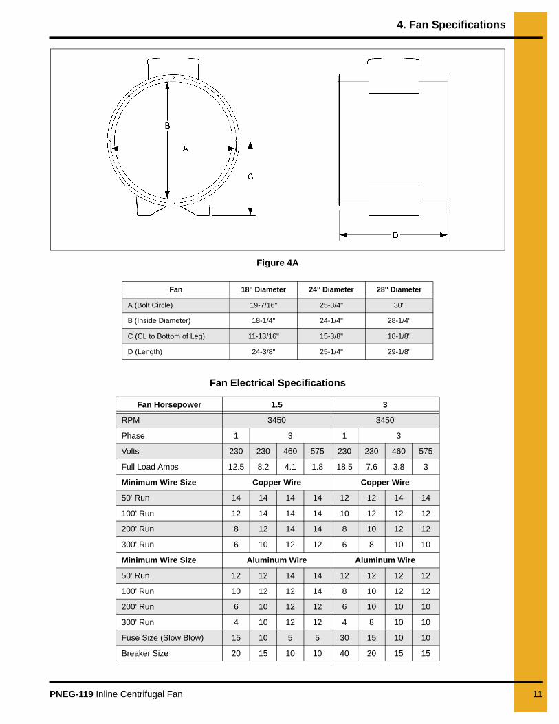
Figure 4A
Fan Electrical Specifications
Fan 18'' Diameter 24'' Diameter 28'' Diameter
A (Bolt Circle) 19-7/16" 25-3/4" 30"
B (Inside Diameter) 18-1/4" 24-1/4" 28-1/4"
C (CL to Bottom of Leg) 11-13/16" 15-3/8" 18-1/8"
D (Length) 24-3/8" 25-1/4" 29-1/8"
Fan Horsepower 1.5 3
RPM 3450 3450
Phase 1 3 1 3
Volts 230 230 460 575 230 230 460 575
Full Load Amps 12.5 8.2 4.1 1.8 18.5 7.6 3.8 3
Minimum Wire Size Copper Wire Copper Wire
50' Run 14 14 14 14 12 12 14 14
100' Run 12 14 14 14 10 12 12 12
200' Run 8 12 14 14 8 10 12 12
300' Run 6 10 12 12 6 8 10 10
Minimum Wire Size Aluminum Wire Aluminum Wire
50' Run 12 12 14 14 12 12 12 12
100' Run 10 12 12 14 8 10 12 12
200' Run 6 10 12 12 6 10 10 10
300' Run 4 10 12 12 4 8 10 10
Fuse Size (Slow Blow) 15 10 5 5 30 15 10 10
Breaker Size 20 15 10 10 40 20 15 15
4. Fan Specifications
12 PNEG-119 Inline Centrifugal Fan
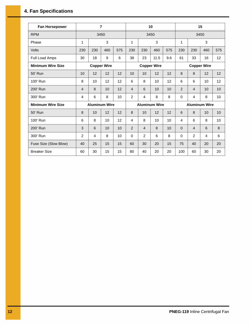
Fan Horsepower 7 10 15
RPM 3450 3450 3450
Phase 1 3 1 3 1 3
Volts 230 230 460 575 230 230 460 575 230 230 460 575
Full Load Amps 30 18 9 6 38 23 11.5 9.6 61 33 16 12
Minimum Wire Size Copper Wire Copper Wire Copper Wire
50' Run 10 12 12 12 10 10 12 12 8 8 12 12
100' Run 8 10 12 12 6 8 10 12 6 6 10 12
200' Run 4 8 10 12 4 6 10 10 2 4 10 10
300' Run 4 6 8 10 2 4 8 8 0 4 8 10
Minimum Wire Size Aluminum Wire Aluminum Wire Aluminum Wire
50' Run 8 10 12 12 8 10 12 12 6 8 10 10
100' Run 6 8 10 12 4 8 10 10 4 6 8 10
200' Run 3 6 10 10 2 4 8 10 0 4 6 8
300' Run 2 4 8 10 0 2 6 8 0 2 4 6
Fuse Size (Slow Blow) 40 25 15 15 60 30 20 15 75 40 20 20
Breaker Size 60 30 15 15 80 40 20 20 100 60 30 20
PNEG-119 Inline Centrifugal Fan 13
5. Fan Installation
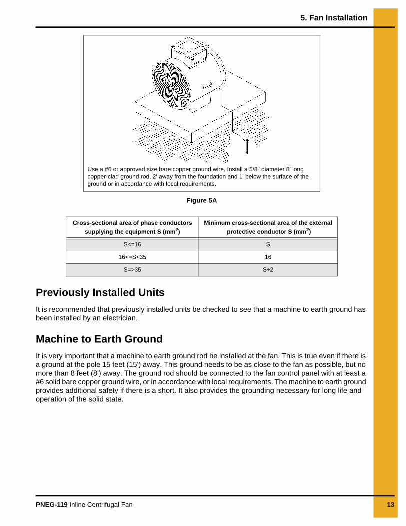
Figure 5A
Previously Installed UnitsIt is recommended that previously installed units be checked to see that a machine to earth ground has been installed by an electrician.
Machine to Earth GroundIt is very important that a machine to earth ground rod be installed at the fan. This is true even if there is a ground at the pole 15 feet (15') away. This ground needs to be as close to the fan as possible, but no more than 8 feet (8') away. The ground rod should be connected to the fan control panel with at least a #6 solid bare copper ground wire, or in accordance with local requirements. The machine to earth ground provides additional safety if there is a short. It also provides the grounding necessary for long life and operation of the solid state.
Cross-sectional area of phase conductors supplying the equipment S (mm2)
Minimum cross-sectional area of the external protective conductor S (mm2)
S<=16 S
16<=S<35 16
S=>35 S÷2
Use a #6 or approved size bare copper ground wire. Install a 5/8" diameter 8' long copper-clad ground rod, 2' away from the foundation and 1' below the surface of the ground or in accordance with local requirements.

5. Fan Installation
14 PNEG-119 Inline Centrifugal Fan
Proper Installation of the Ground Rod(Ground rods and wires are not supplied by GSI.) It is recommended that the rod not be driven into dry ground. The following steps ensure proper ground rod installation:
1. Dig a hole large enough to hold 1 to 2 gallons of water.
2. Fill hole with water.
3. Insert rod through water and jab it into the ground.
4. Continue jabbing the rod up and down, the water will work its way down the hole, making it possible to work the rod completely into the ground. This method of installing the rod gives a good conductive bond with the surrounding soil.
5. Connect the bare copper ground wire to the rod with the proper ground rod clamp.
6. Connect the bare ground wire to the fan control boxes with a grounding lug. (See Figure 5A on Page 13.)
7. Ground wire must not have any breaks or splices. Insulated wire is not recommended for grounding.
Figure 5B
Dig a hole large enough to hold 1 or 2 gallons of water. Work the ground rod into the earth until it is completely in the ground.
PNEG-119 Inline Centrifugal Fan 15
6. Fan Operation
Start-upOn initial start-up of the fan, run it momentarily to make sure that the fan blade is rotating in the proper direction and airflow is correct. If not, change motor direction using instructions on the motor.
Proper installation and start-up ensures many years of trouble-free operation.
Maintaining Grain QualityTo properly maintain the quality of stored grain, it is necessary to keep the grain dry, cool and insect free. Any one of these problems can contribute to spoilage. Wet, warm grain promotes insect growth as well as grain spoilage. Cool, dry grain can keep for long periods of time.
It is recommended that the grain be kept cool (avoid freezing as freezing can reduce quality). Grain should be cooled through the fall and winter, warmed in the spring and summer.
Grain StorageAverage grain temperature should be above 35°F in the winter and below 65°F in the summer. Always try to keep the grain within 10°F-15°F of the average monthly outside temperature. This means grain may need to be aerated on warm days during the winter to stay above 35°F when freezing temperatures are predominate.
During the summer it may be necessary to aerate the grain on cool nights, so the 65°F temperature is not exceeded during the hot days of summer.
Conditions and requirements may vary from area to area. We suggest that you contact the local Agriculture Extension Office or State Agriculture University for more exact guidelines.
If the grain is to be stored more than one (1) year, it has to be recooled the following fall and winter, repeating the process as long as the grain is in storage. Frequent and regular inspection (at least weekly during fall and spring) is the best prevention against grain spoilage).
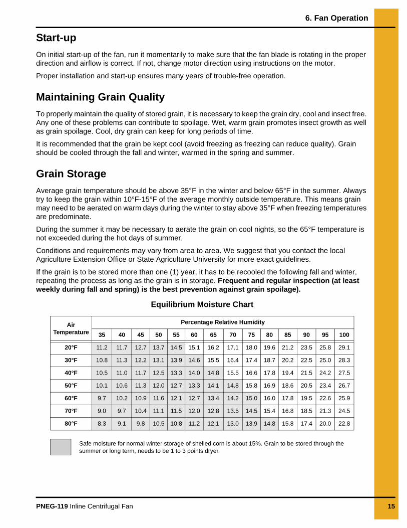
Equilibrium Moisture Chart
Air Temperature
Percentage Relative Humidity
35 40 45 50 55 60 65 70 75 80 85 90 95 100
20°F 11.2 11.7 12.7 13.7 14.5 15.1 16.2 17.1 18.0 19.6 21.2 23.5 25.8 29.1
30°F 10.8 11.3 12.2 13.1 13.9 14.6 15.5 16.4 17.4 18.7 20.2 22.5 25.0 28.3
40°F 10.5 11.0 11.7 12.5 13.3 14.0 14.8 15.5 16.6 17.8 19.4 21.5 24.2 27.5
50°F 10.1 10.6 11.3 12.0 12.7 13.3 14.1 14.8 15.8 16.9 18.6 20.5 23.4 26.7
60°F 9.7 10.2 10.9 11.6 12.1 12.7 13.4 14.2 15.0 16.0 17.8 19.5 22.6 25.9
70°F 9.0 9.7 10.4 11.1 11.5 12.0 12.8 13.5 14.5 15.4 16.8 18.5 21.3 24.5
80°F 8.3 9.1 9.8 10.5 10.8 11.2 12.1 13.0 13.9 14.8 15.8 17.4 20.0 22.8
Safe moisture for normal winter storage of shelled corn is about 15%. Grain to be stored through the summer or long term, needs to be 1 to 3 points dryer.
6. Fan Operation
16 PNEG-119 Inline Centrifugal Fan
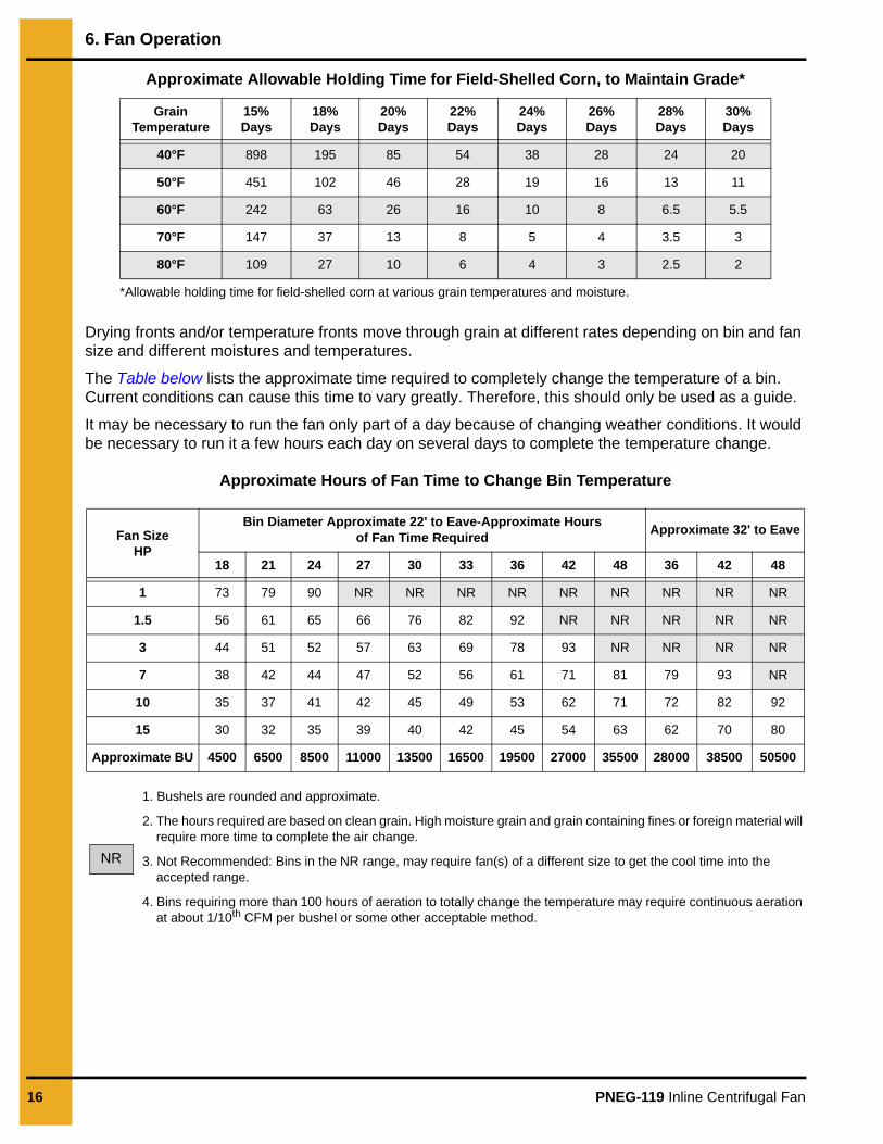
Approximate Allowable Holding Time for Field-Shelled Corn, to Maintain Grade*
Drying fronts and/or temperature fronts move through grain at different rates depending on bin and fan size and different moistures and temperatures.
The Table below lists the approximate time required to completely change the temperature of a bin. Current conditions can cause this time to vary greatly. Therefore, this should only be used as a guide.
It may be necessary to run the fan only part of a day because of changing weather conditions. It would be necessary to run it a few hours each day on several days to complete the temperature change.
Approximate Hours of Fan Time to Change Bin Temperature
1. Bushels are rounded and approximate.
2. The hours required are based on clean grain. High moisture grain and grain containing fines or foreign material will require more time to complete the air change.
3. Not Recommended: Bins in the NR range, may require fan(s) of a different size to get the cool time into the accepted range.
4. Bins requiring more than 100 hours of aeration to totally change the temperature may require continuous aeration at about 1/10th CFM per bushel or some other acceptable method.
Grain Temperature
15% Days
18% Days
20% Days
22% Days
24% Days
26% Days
28% Days
30% Days
40°F 898 195 85 54 38 28 24 20
50°F 451 102 46 28 19 16 13 11
60°F 242 63 26 16 10 8 6.5 5.5
70°F 147 37 13 8 5 4 3.5 3
80°F 109 27 10 6 4 3 2.5 2
*Allowable holding time for field-shelled corn at various grain temperatures and moisture.
Fan Size HP
Bin Diameter Approximate 22' to Eave-Approximate Hours of Fan Time Required Approximate 32' to Eave
18 21 24 27 30 33 36 42 48 36 42 48
1 73 79 90 NR NR NR NR NR NR NR NR NR
1.5 56 61 65 66 76 82 92 NR NR NR NR NR
3 44 51 52 57 63 69 78 93 NR NR NR NR
7 38 42 44 47 52 56 61 71 81 79 93 NR
10 35 37 41 42 45 49 53 62 71 72 82 92
15 30 32 35 39 40 42 45 54 63 62 70 80
Approximate BU 4500 6500 8500 11000 13500 16500 19500 27000 35500 28000 38500 50500
NR
PNEG-119 Inline Centrifugal Fan 17
7. Fan Service
Motors used in fan units are all standard NEMA frame motors and are specially designed for use in crop drying applications. Replacement parts for these motors are handled by authorized service stations of the various motor manufacturers.
1. Always disconnect and lock out power before working on or around fan motor and electrical components.
2. Malfunctioning electrical components should be checked by a qualified electrician.
3. For extra motor life, any electric motor should be run for 30 minutes, once a month. This will help eliminate any damaging moisture build-up in the motor and bearings.
4. Fans setting idle in the summer offer an excellent place for mud dobbers to build their nests. A mud dobber nest on the back of the fan blade will cause the fan to be out of balance and vibrate.
This is a ball bearing motor. The bearings have been given initial lubrication at the factory. Motors without regreasing capability are factory lubricated for normal bearing life.
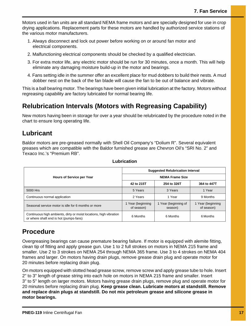
Relubrication Intervals (Motors with Regreasing Capability)New motors having been in storage for over a year should be relubricated by the procedure noted in the chart to ensure long operating life.
LubricantBaldor motors are pre-greased normally with Shell Oil Company’s “Dolium R”. Several equivalent greases which are compatible with the Baldor furnished grease are Chevron Oil’s “SRI No. 2” and Texaco Inc.’s “Premium RB”.
Lubrication
ProcedureOvergreasing bearings can cause premature bearing failure. If motor is equipped with alemite fitting, clean tip of fitting and apply grease gun. Use 1 to 2 full strokes on motors in NEMA 215 frame and smaller. Use 2 to 3 strokes on NEMA 254 through NEMA 365 frame. Use 3 to 4 strokes on NEMA 404 frames and larger. On motors having drain plugs, remove grease drain plug and operate motor for 20 minutes before replacing drain plug.
On motors equipped with slotted head grease screw, remove screw and apply grease tube to hole. Insert 2" to 3" length of grease string into each hole on motors in NEMA 215 frame and smaller. Insert 3" to 5" length on larger motors. Motors having grease drain plugs, remove plug and operate motor for 20 minutes before replacing drain plug. Keep grease clean. Lubricate motors at standstill. Remove and replace drain plugs at standstill. Do not mix petroleum grease and silicone grease in motor bearings.
Hours of Service per Year
Suggested Relubrication Interval
NEMA Frame Size
42 to 215T 254 to 326T 364 to 447T
5000 Hrs 5 Years 3 Years 1 Year
Continuous normal application 2 Years 1 Year 9 Months
Seasonal service motor is idle for 6 months or more 1 Year (beginning of season)
1 Year (beginning of season)
1 Year (beginning of season)
Continuous high ambients, dirty or moist locations, high vibration or where shaft end is hot (pumps-fans) 6 Months 6 Months 6 Months
18 PNEG-119 Inline Centrifugal Fan
8. Troubleshooting
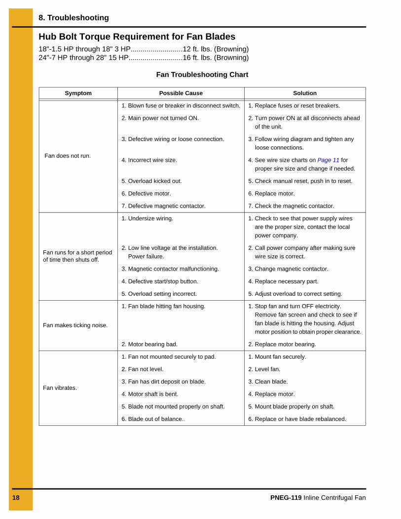
Hub Bolt Torque Requirement for Fan Blades18"-1.5 HP through 18" 3 HP..........................12 ft. lbs. (Browning)24"-7 HP through 28" 15 HP...........................16 ft. lbs. (Browning)
Fan Troubleshooting Chart
Symptom Possible Cause Solution
Fan does not run.
1. Blown fuse or breaker in disconnect switch. 1. Replace fuses or reset breakers.
2. Main power not turned ON. 2. Turn power ON at all disconnects ahead of the unit.
3. Defective wiring or loose connection. 3. Follow wiring diagram and tighten any loose connections.
4. Incorrect wire size. 4. See wire size charts on Page 11 for proper sire size and change if needed.
5. Overload kicked out. 5. Check manual reset, push in to reset.
6. Defective motor. 6. Replace motor.
7. Defective magnetic contactor. 7. Check the magnetic contactor.
Fan runs for a short period of time then shuts off.
1. Undersize wiring. 1. Check to see that power supply wires are the proper size, contact the local power company.
2. Low line voltage at the installation. Power failure.
2. Call power company after making sure wire size is correct.
3. Magnetic contactor malfunctioning. 3. Change magnetic contactor.
4. Defective start/stop button. 4. Replace necessary part.
5. Overload setting incorrect. 5. Adjust overload to correct setting.
Fan makes ticking noise.
1. Fan blade hitting fan housing. 1. Stop fan and turn OFF electricity. Remove fan screen and check to see if fan blade is hitting the housing. Adjust motor position to obtain proper clearance.
2. Motor bearing bad. 2. Replace motor bearing.
Fan vibrates.
1. Fan not mounted securely to pad. 1. Mount fan securely.
2. Fan not level. 2. Level fan.
3. Fan has dirt deposit on blade. 3. Clean blade.
4. Motor shaft is bent. 4. Replace motor.
5. Blade not mounted properly on shaft. 5. Mount blade properly on shaft.
6. Blade out of balance. 6. Replace or have blade rebalanced.
PNEG-119 Inline Centrifugal Fan 19
9. Parts List
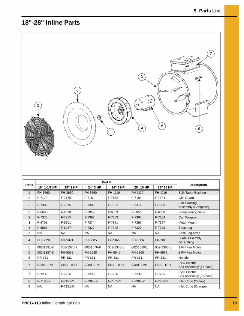
18"-28" Inline Parts
Ref #Part #
Description18'' 1-1/2 HP 18'' 3 HP 24'' 3 HP 24'' 7 HP 28'' 10 HP 28'' 15 HP
1 FH-3660 FH-3660 FH-3660 FH-1119 FH-1119 FH-1119 Split Taper Bushing2 F-7179 F-7179 F-7182 F-7182 F-7184 F-7184 Grill Guard
3 F-7388 F-7376 F-7383 F-7362 F-7377 F-7368 Fan HousingAssembly (Complete)
3 F-6698 F-6698 F-6859 F-6859 F-6858 F-6858 Straightening Vane3 F-7375 F-7375 F-7363 F-7363 F-7364 F-7364 Can Wrapper3 F-6701 F-6701 F-7374 F-7321 F-7367 F-7327 Motor Mount3 F-6987 F-6987 F-7322 F-7322 F-7329 F-7329 Base Leg3 NA NA NA NA NA NA Base Leg Strap
4 FH-5820 FH-5821 FH-6005 FH-5822 FH-6006 FH-5823 Blade Assembly w/ Bushing
5 002-1391-8 002-1376-9 002-1376-9 002-1378-5 002-1380-1 002-1383-5 1 PH Fan Motor5 002-1387-6 FH-5538 FH-5538 FH-5646 FH-6965 FH-6967 3 PH Fan Motor6 PR-331 PR-331 PR-331 PR-331 PR-331 PR-331 Handle
7 CBAF-1PH CBAF-1PH CBAF-1PH CBAF-1PH CBAF-1PH CBAF-1PH PVC Electric Box Assembly (1 Phase)
7 F-7236 F-7236 F-7236 F-7236 F-7236 F-7236 PVC Electric Box Assembly (3 Phase)
8 F-7180-Y F-7181-Y F-7365-Y F-7365-Y F-7366-Y F-7366-Y Inlet Cone (Yellow)8 NA F-7181-O NA NA NA NA Inlet Cone (Orange)
20 PNEG-119 Inline Centrifugal Fan
10. Wiring Diagrams
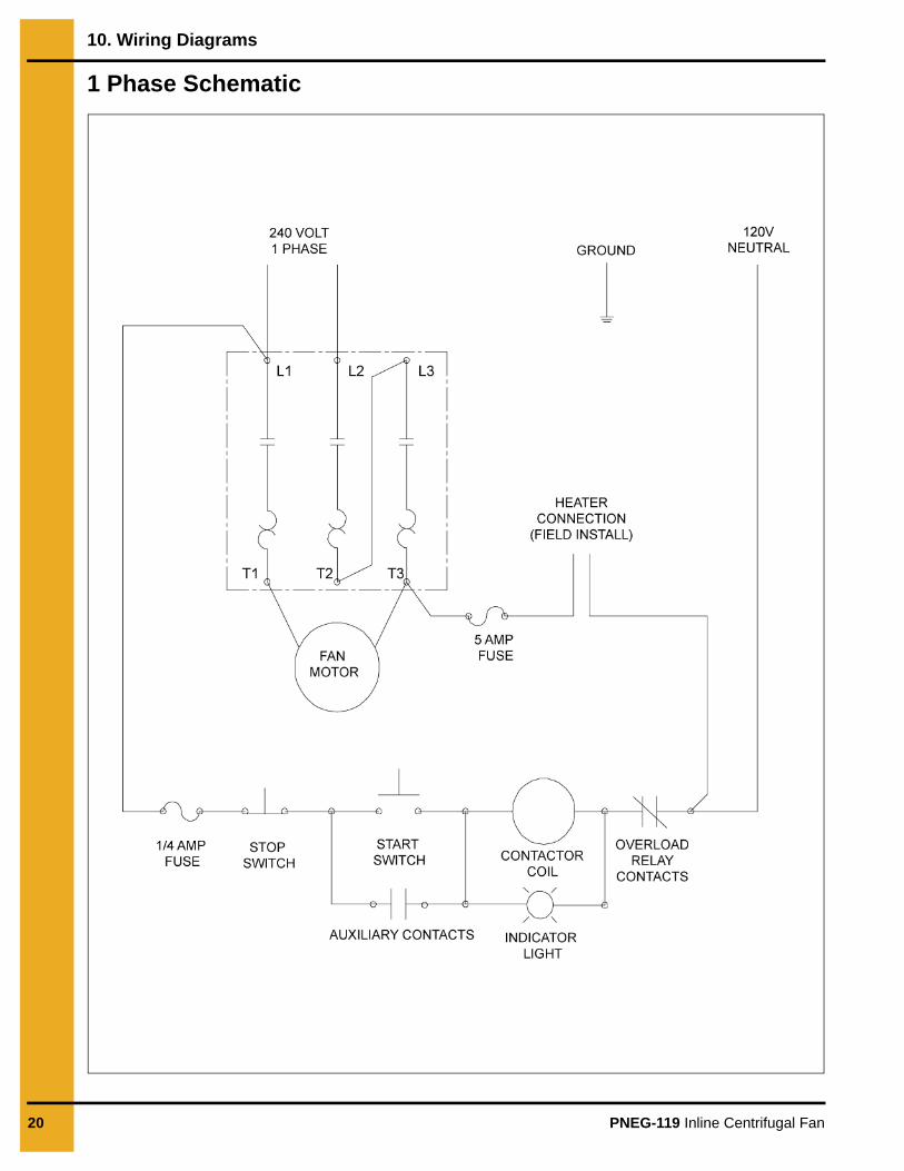
1 Phase Schematic
10. Wiring Diagrams
PNEG-119 Inline Centrifugal Fan 21
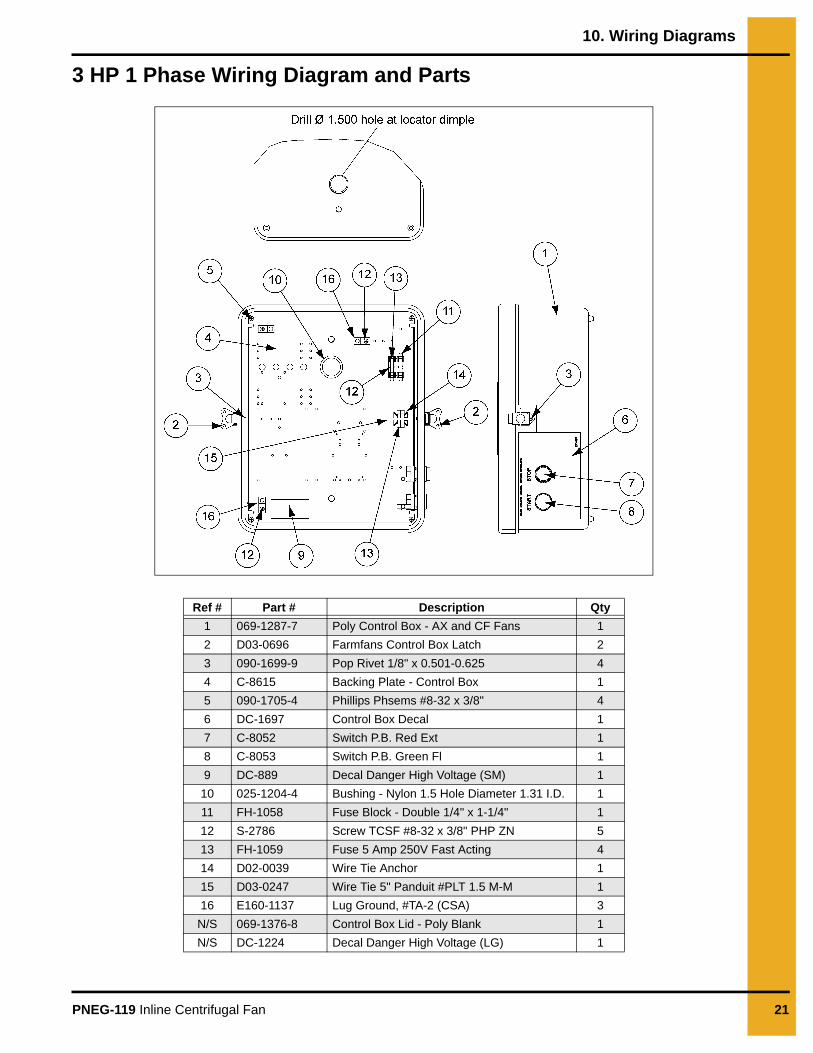
3 HP 1 Phase Wiring Diagram and Parts
Ref # Part # Description Qty1 069-1287-7 Poly Control Box - AX and CF Fans 12 D03-0696 Farmfans Control Box Latch 23 090-1699-9 Pop Rivet 1/8" x 0.501-0.625 44 C-8615 Backing Plate - Control Box 15 090-1705-4 Phillips Phsems #8-32 x 3/8" 46 DC-1697 Control Box Decal 17 C-8052 Switch P.B. Red Ext 18 C-8053 Switch P.B. Green Fl 19 DC-889 Decal Danger High Voltage (SM) 1
10 025-1204-4 Bushing - Nylon 1.5 Hole Diameter 1.31 I.D. 111 FH-1058 Fuse Block - Double 1/4" x 1-1/4" 112 S-2786 Screw TCSF #8-32 x 3/8" PHP ZN 513 FH-1059 Fuse 5 Amp 250V Fast Acting 414 D02-0039 Wire Tie Anchor 115 D03-0247 Wire Tie 5" Panduit #PLT 1.5 M-M 116 E160-1137 Lug Ground, #TA-2 (CSA) 3N/S 069-1376-8 Control Box Lid - Poly Blank 1N/S DC-1224 Decal Danger High Voltage (LG) 1
10. Wiring Diagrams
22 PNEG-119 Inline Centrifugal Fan
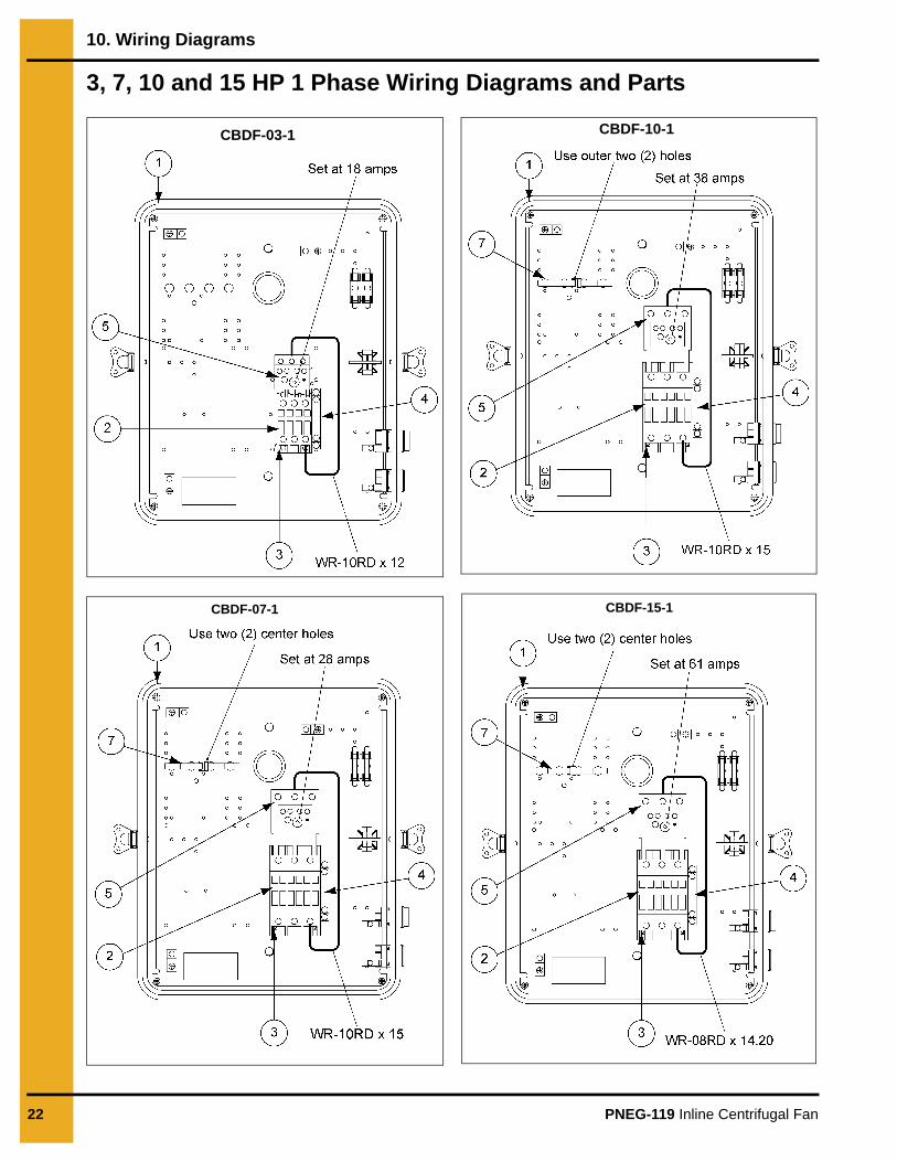
3, 7, 10 and 15 HP 1 Phase Wiring Diagrams and Parts
CBDF-03-1
CBDF-07-1
CBDF-10-1
CBDF-15-1
10. Wiring Diagrams
PNEG-119 Inline Centrifugal Fan 23
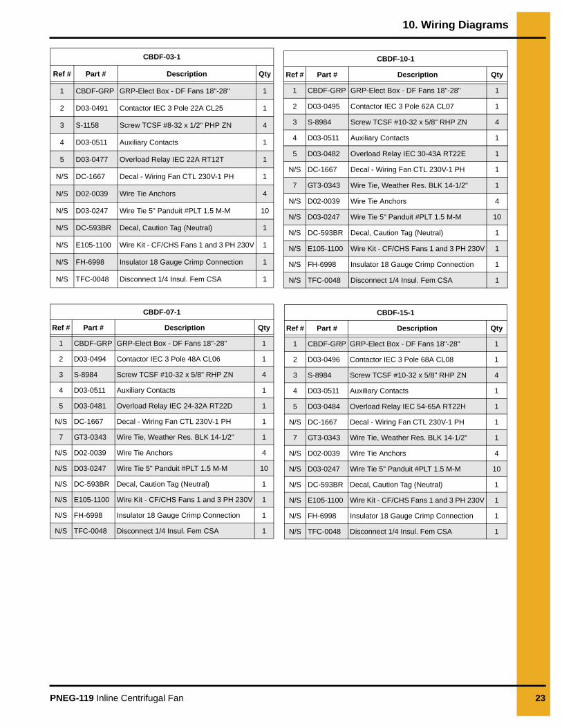
CBDF-03-1
Ref # Part # Description Qty
1 CBDF-GRP GRP-Elect Box - DF Fans 18"-28" 1
2 D03-0491 Contactor IEC 3 Pole 22A CL25 1
3 S-1158 Screw TCSF #8-32 x 1/2" PHP ZN 4
4 D03-0511 Auxiliary Contacts 1
5 D03-0477 Overload Relay IEC 22A RT12T 1
N/S DC-1667 Decal - Wiring Fan CTL 230V-1 PH 1
N/S D02-0039 Wire Tie Anchors 4
N/S D03-0247 Wire Tie 5" Panduit #PLT 1.5 M-M 10
N/S DC-593BR Decal, Caution Tag (Neutral) 1
N/S E105-1100 Wire Kit - CF/CHS Fans 1 and 3 PH 230V 1
N/S FH-6998 Insulator 18 Gauge Crimp Connection 1
N/S TFC-0048 Disconnect 1/4 Insul. Fem CSA 1
CBDF-07-1
Ref # Part # Description Qty
1 CBDF-GRP GRP-Elect Box - DF Fans 18"-28" 1
2 D03-0494 Contactor IEC 3 Pole 48A CL06 1
3 S-8984 Screw TCSF #10-32 x 5/8" RHP ZN 4
4 D03-0511 Auxiliary Contacts 1
5 D03-0481 Overload Relay IEC 24-32A RT22D 1
N/S DC-1667 Decal - Wiring Fan CTL 230V-1 PH 1
7 GT3-0343 Wire Tie, Weather Res. BLK 14-1/2" 1
N/S D02-0039 Wire Tie Anchors 4
N/S D03-0247 Wire Tie 5" Panduit #PLT 1.5 M-M 10
N/S DC-593BR Decal, Caution Tag (Neutral) 1
N/S E105-1100 Wire Kit - CF/CHS Fans 1 and 3 PH 230V 1
N/S FH-6998 Insulator 18 Gauge Crimp Connection 1
N/S TFC-0048 Disconnect 1/4 Insul. Fem CSA 1
CBDF-10-1
Ref # Part # Description Qty
1 CBDF-GRP GRP-Elect Box - DF Fans 18"-28" 1
2 D03-0495 Contactor IEC 3 Pole 62A CL07 1
3 S-8984 Screw TCSF #10-32 x 5/8" RHP ZN 4
4 D03-0511 Auxiliary Contacts 1
5 D03-0482 Overload Relay IEC 30-43A RT22E 1
N/S DC-1667 Decal - Wiring Fan CTL 230V-1 PH 1
7 GT3-0343 Wire Tie, Weather Res. BLK 14-1/2" 1
N/S D02-0039 Wire Tie Anchors 4
N/S D03-0247 Wire Tie 5" Panduit #PLT 1.5 M-M 10
N/S DC-593BR Decal, Caution Tag (Neutral) 1
N/S E105-1100 Wire Kit - CF/CHS Fans 1 and 3 PH 230V 1
N/S FH-6998 Insulator 18 Gauge Crimp Connection 1
N/S TFC-0048 Disconnect 1/4 Insul. Fem CSA 1
CBDF-15-1
Ref # Part # Description Qty
1 CBDF-GRP GRP-Elect Box - DF Fans 18"-28" 1
2 D03-0496 Contactor IEC 3 Pole 68A CL08 1
3 S-8984 Screw TCSF #10-32 x 5/8" RHP ZN 4
4 D03-0511 Auxiliary Contacts 1
5 D03-0484 Overload Relay IEC 54-65A RT22H 1
N/S DC-1667 Decal - Wiring Fan CTL 230V-1 PH 1
7 GT3-0343 Wire Tie, Weather Res. BLK 14-1/2" 1
N/S D02-0039 Wire Tie Anchors 4
N/S D03-0247 Wire Tie 5" Panduit #PLT 1.5 M-M 10
N/S DC-593BR Decal, Caution Tag (Neutral) 1
N/S E105-1100 Wire Kit - CF/CHS Fans 1 and 3 PH 230V 1
N/S FH-6998 Insulator 18 Gauge Crimp Connection 1
N/S TFC-0048 Disconnect 1/4 Insul. Fem CSA 1

24 PNEG-119 Inline Centrifugal Fan
NOTES
10. Wiring Diagrams
PNEG-119 Inline Centrifugal Fan 25
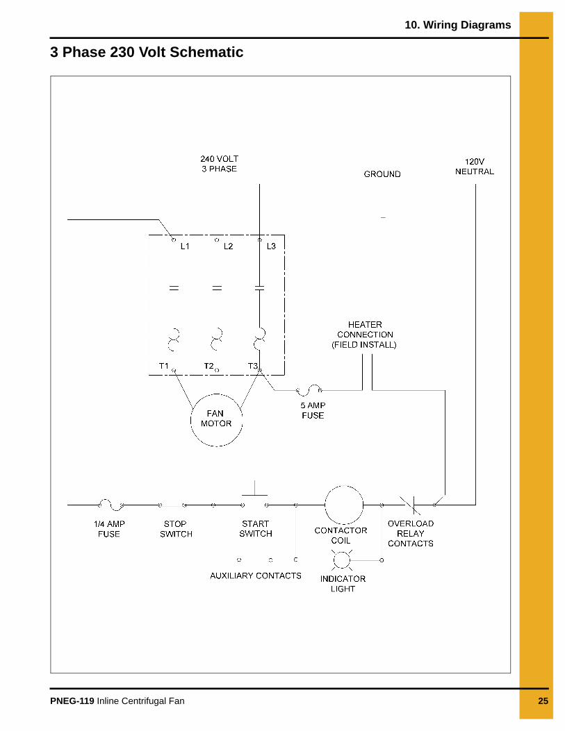
3 Phase 230 Volt Schematic
10. Wiring Diagrams
26 PNEG-119 Inline Centrifugal Fan
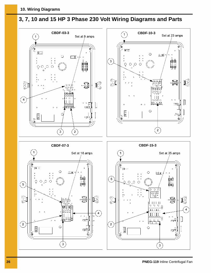
3, 7, 10 and 15 HP 3 Phase 230 Volt Wiring Diagrams and Parts
CBDF-03-3CBDF-03-3
CBDF-07-3
CBDF-10-3
CBDF-15-3
10. Wiring Diagrams
PNEG-119 Inline Centrifugal Fan 27
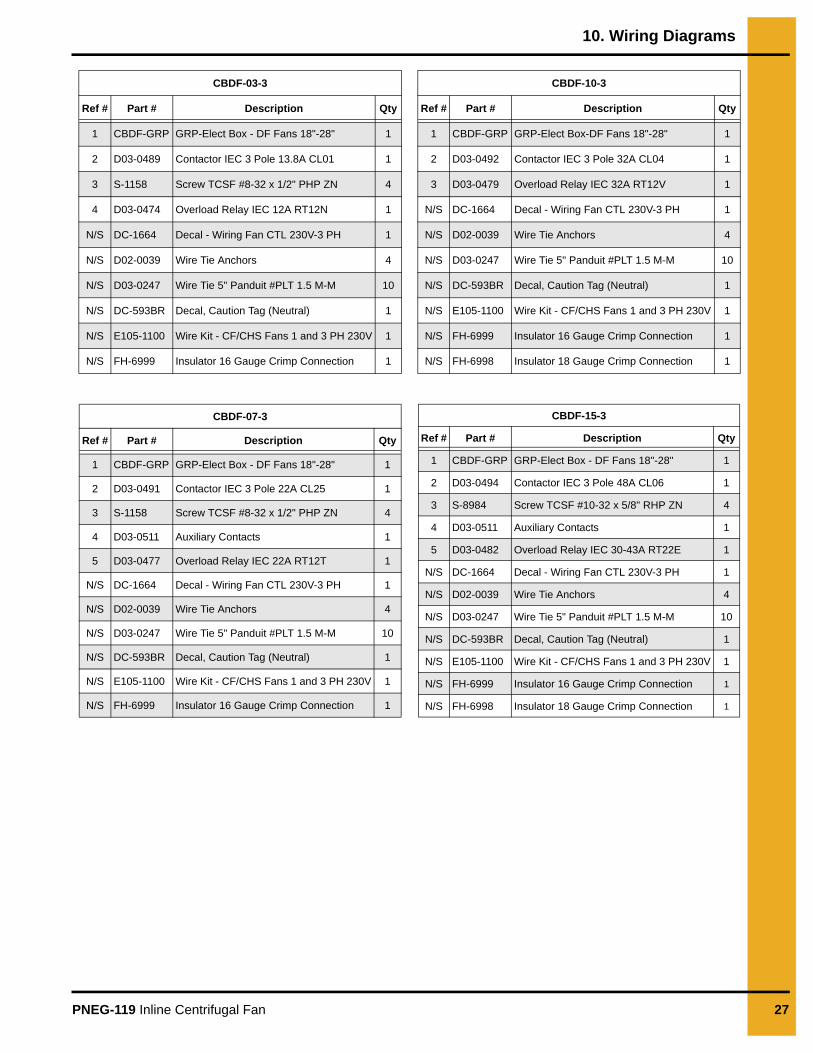
CBDF-03-3
Ref # Part # Description Qty
1 CBDF-GRP GRP-Elect Box - DF Fans 18"-28" 1
2 D03-0489 Contactor IEC 3 Pole 13.8A CL01 1
3 S-1158 Screw TCSF #8-32 x 1/2" PHP ZN 4
4 D03-0474 Overload Relay IEC 12A RT12N 1
N/S DC-1664 Decal - Wiring Fan CTL 230V-3 PH 1
N/S D02-0039 Wire Tie Anchors 4
N/S D03-0247 Wire Tie 5" Panduit #PLT 1.5 M-M 10
N/S DC-593BR Decal, Caution Tag (Neutral) 1
N/S E105-1100 Wire Kit - CF/CHS Fans 1 and 3 PH 230V 1
N/S FH-6999 Insulator 16 Gauge Crimp Connection 1
CBDF-07-3
Ref # Part # Description Qty
1 CBDF-GRP GRP-Elect Box - DF Fans 18"-28" 1
2 D03-0491 Contactor IEC 3 Pole 22A CL25 1
3 S-1158 Screw TCSF #8-32 x 1/2" PHP ZN 4
4 D03-0511 Auxiliary Contacts 1
5 D03-0477 Overload Relay IEC 22A RT12T 1
N/S DC-1664 Decal - Wiring Fan CTL 230V-3 PH 1
N/S D02-0039 Wire Tie Anchors 4
N/S D03-0247 Wire Tie 5" Panduit #PLT 1.5 M-M 10
N/S DC-593BR Decal, Caution Tag (Neutral) 1
N/S E105-1100 Wire Kit - CF/CHS Fans 1 and 3 PH 230V 1
N/S FH-6999 Insulator 16 Gauge Crimp Connection 1
CBDF-10-3
Ref # Part # Description Qty
1 CBDF-GRP GRP-Elect Box-DF Fans 18"-28" 1
2 D03-0492 Contactor IEC 3 Pole 32A CL04 1
3 D03-0479 Overload Relay IEC 32A RT12V 1
N/S DC-1664 Decal - Wiring Fan CTL 230V-3 PH 1
N/S D02-0039 Wire Tie Anchors 4
N/S D03-0247 Wire Tie 5" Panduit #PLT 1.5 M-M 10
N/S DC-593BR Decal, Caution Tag (Neutral) 1
N/S E105-1100 Wire Kit - CF/CHS Fans 1 and 3 PH 230V 1
N/S FH-6999 Insulator 16 Gauge Crimp Connection 1
N/S FH-6998 Insulator 18 Gauge Crimp Connection 1
CBDF-15-3
Ref # Part # Description Qty
1 CBDF-GRP GRP-Elect Box - DF Fans 18"-28" 1
2 D03-0494 Contactor IEC 3 Pole 48A CL06 1
3 S-8984 Screw TCSF #10-32 x 5/8" RHP ZN 4
4 D03-0511 Auxiliary Contacts 1
5 D03-0482 Overload Relay IEC 30-43A RT22E 1
N/S DC-1664 Decal - Wiring Fan CTL 230V-3 PH 1
N/S D02-0039 Wire Tie Anchors 4
N/S D03-0247 Wire Tie 5" Panduit #PLT 1.5 M-M 10
N/S DC-593BR Decal, Caution Tag (Neutral) 1
N/S E105-1100 Wire Kit - CF/CHS Fans 1 and 3 PH 230V 1
N/S FH-6999 Insulator 16 Gauge Crimp Connection 1
N/S FH-6998 Insulator 18 Gauge Crimp Connection 1

28 PNEG-119 Inline Centrifugal Fan
NOTES

10. Wiring Diagrams
PNEG-119 Inline Centrifugal Fan 29
3 Phase 460 Volt Schematic
10. Wiring Diagrams
30 PNEG-119 Inline Centrifugal Fan
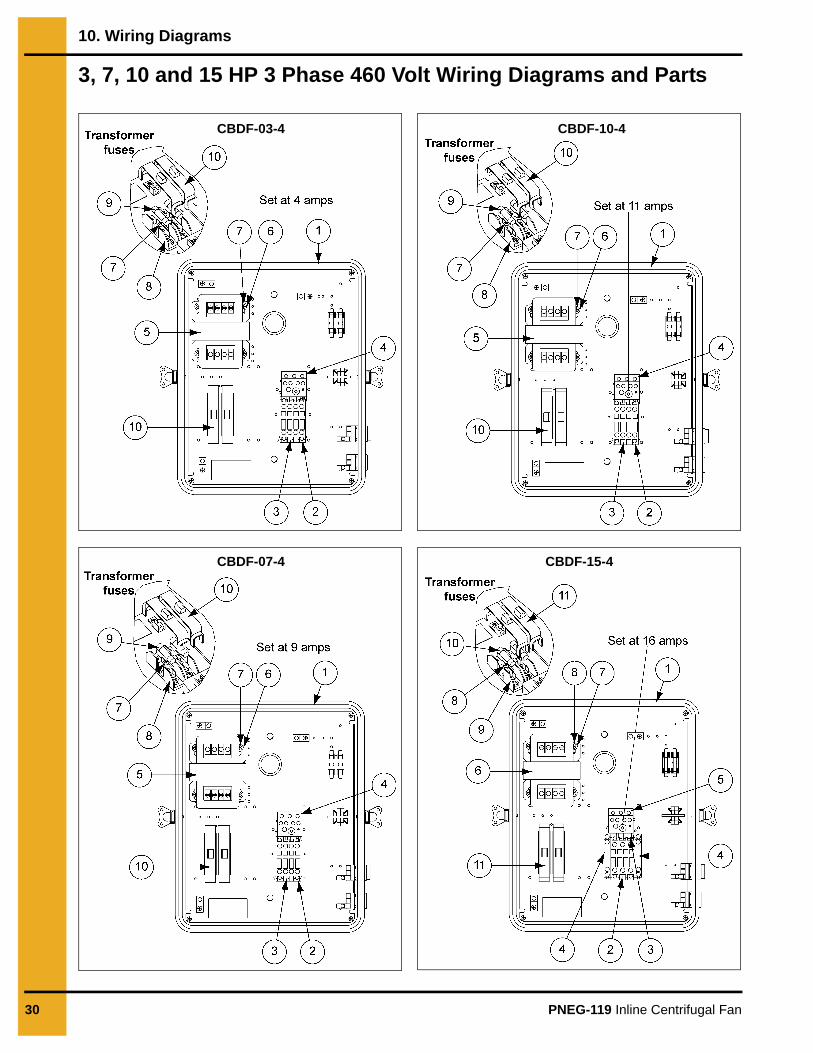
3, 7, 10 and 15 HP 3 Phase 460 Volt Wiring Diagrams and Parts
CBDF-03-4
CBDF-07-4
CBDF-10-4
CBDF-15-4
10. Wiring Diagrams
PNEG-119 Inline Centrifugal Fan 31
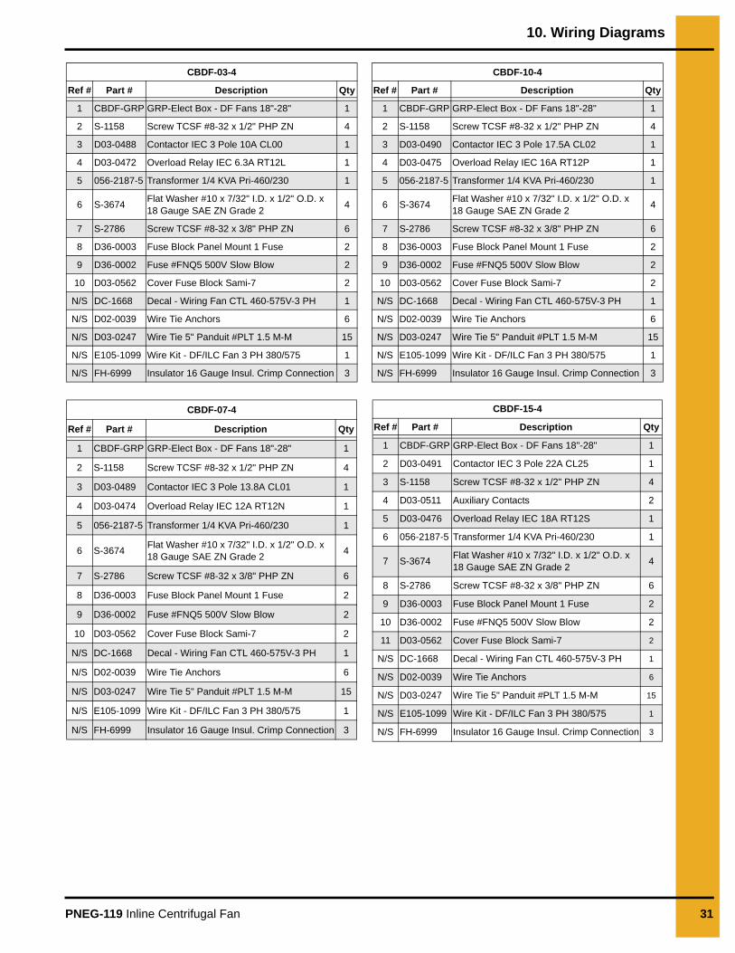
CBDF-03-4
Ref # Part # Description Qty
1 CBDF-GRP GRP-Elect Box - DF Fans 18"-28" 1
2 S-1158 Screw TCSF #8-32 x 1/2" PHP ZN 4
3 D03-0488 Contactor IEC 3 Pole 10A CL00 1
4 D03-0472 Overload Relay IEC 6.3A RT12L 1
5 056-2187-5 Transformer 1/4 KVA Pri-460/230 1
6 S-3674 Flat Washer #10 x 7/32" I.D. x 1/2" O.D. x 18 Gauge SAE ZN Grade 2 4
7 S-2786 Screw TCSF #8-32 x 3/8" PHP ZN 6
8 D36-0003 Fuse Block Panel Mount 1 Fuse 2
9 D36-0002 Fuse #FNQ5 500V Slow Blow 2
10 D03-0562 Cover Fuse Block Sami-7 2
N/S DC-1668 Decal - Wiring Fan CTL 460-575V-3 PH 1
N/S D02-0039 Wire Tie Anchors 6
N/S D03-0247 Wire Tie 5" Panduit #PLT 1.5 M-M 15
N/S E105-1099 Wire Kit - DF/ILC Fan 3 PH 380/575 1
N/S FH-6999 Insulator 16 Gauge Insul. Crimp Connection 3
CBDF-07-4
Ref # Part # Description Qty
1 CBDF-GRP GRP-Elect Box - DF Fans 18"-28" 1
2 S-1158 Screw TCSF #8-32 x 1/2" PHP ZN 4
3 D03-0489 Contactor IEC 3 Pole 13.8A CL01 1
4 D03-0474 Overload Relay IEC 12A RT12N 1
5 056-2187-5 Transformer 1/4 KVA Pri-460/230 1
6 S-3674 Flat Washer #10 x 7/32" I.D. x 1/2" O.D. x 18 Gauge SAE ZN Grade 2 4
7 S-2786 Screw TCSF #8-32 x 3/8" PHP ZN 6
8 D36-0003 Fuse Block Panel Mount 1 Fuse 2
9 D36-0002 Fuse #FNQ5 500V Slow Blow 2
10 D03-0562 Cover Fuse Block Sami-7 2
N/S DC-1668 Decal - Wiring Fan CTL 460-575V-3 PH 1
N/S D02-0039 Wire Tie Anchors 6
N/S D03-0247 Wire Tie 5" Panduit #PLT 1.5 M-M 15
N/S E105-1099 Wire Kit - DF/ILC Fan 3 PH 380/575 1
N/S FH-6999 Insulator 16 Gauge Insul. Crimp Connection 3
CBDF-10-4
Ref # Part # Description Qty
1 CBDF-GRP GRP-Elect Box - DF Fans 18"-28" 1
2 S-1158 Screw TCSF #8-32 x 1/2" PHP ZN 4
3 D03-0490 Contactor IEC 3 Pole 17.5A CL02 1
4 D03-0475 Overload Relay IEC 16A RT12P 1
5 056-2187-5 Transformer 1/4 KVA Pri-460/230 1
6 S-3674 Flat Washer #10 x 7/32" I.D. x 1/2" O.D. x 18 Gauge SAE ZN Grade 2 4
7 S-2786 Screw TCSF #8-32 x 3/8" PHP ZN 6
8 D36-0003 Fuse Block Panel Mount 1 Fuse 2
9 D36-0002 Fuse #FNQ5 500V Slow Blow 2
10 D03-0562 Cover Fuse Block Sami-7 2
N/S DC-1668 Decal - Wiring Fan CTL 460-575V-3 PH 1
N/S D02-0039 Wire Tie Anchors 6
N/S D03-0247 Wire Tie 5" Panduit #PLT 1.5 M-M 15
N/S E105-1099 Wire Kit - DF/ILC Fan 3 PH 380/575 1
N/S FH-6999 Insulator 16 Gauge Insul. Crimp Connection 3
CBDF-15-4
Ref # Part # Description Qty
1 CBDF-GRP GRP-Elect Box - DF Fans 18"-28" 1
2 D03-0491 Contactor IEC 3 Pole 22A CL25 1
3 S-1158 Screw TCSF #8-32 x 1/2" PHP ZN 4
4 D03-0511 Auxiliary Contacts 2
5 D03-0476 Overload Relay IEC 18A RT12S 1
6 056-2187-5 Transformer 1/4 KVA Pri-460/230 1
7 S-3674 Flat Washer #10 x 7/32" I.D. x 1/2" O.D. x 18 Gauge SAE ZN Grade 2 4
8 S-2786 Screw TCSF #8-32 x 3/8" PHP ZN 6
9 D36-0003 Fuse Block Panel Mount 1 Fuse 2
10 D36-0002 Fuse #FNQ5 500V Slow Blow 2
11 D03-0562 Cover Fuse Block Sami-7 2
N/S DC-1668 Decal - Wiring Fan CTL 460-575V-3 PH 1
N/S D02-0039 Wire Tie Anchors 6
N/S D03-0247 Wire Tie 5" Panduit #PLT 1.5 M-M 15
N/S E105-1099 Wire Kit - DF/ILC Fan 3 PH 380/575 1
N/S FH-6999 Insulator 16 Gauge Insul. Crimp Connection 3

32 PNEG-119 Inline Centrifugal Fan
NOTES
10. Wiring Diagrams
PNEG-119 Inline Centrifugal Fan 33
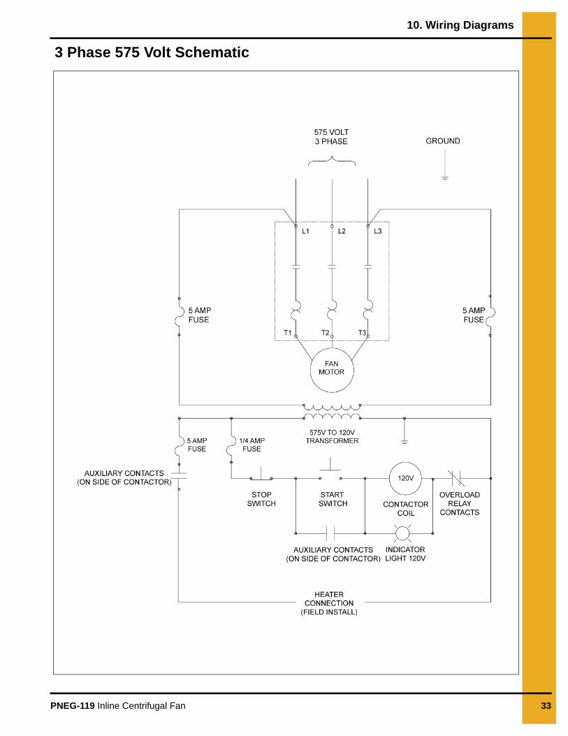
3 Phase 575 Volt Schematic
10. Wiring Diagrams
34 PNEG-119 Inline Centrifugal Fan
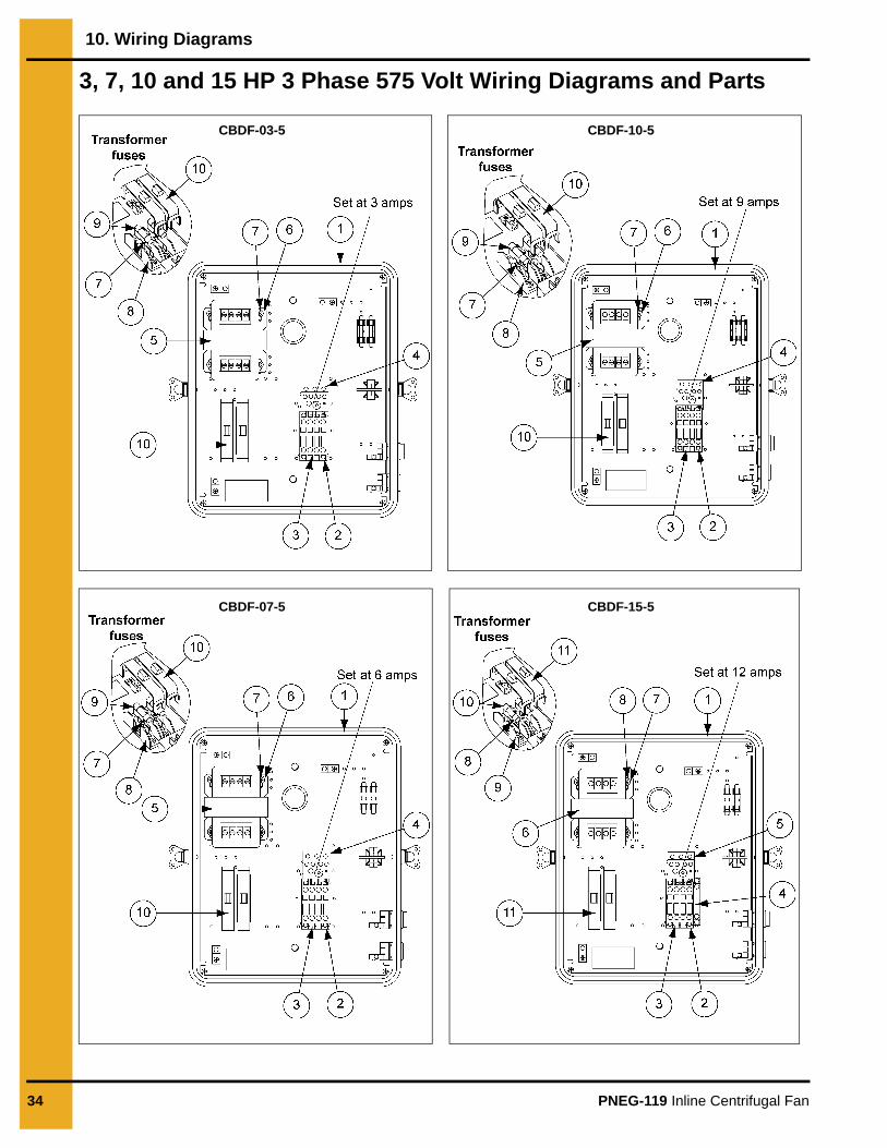
3, 7, 10 and 15 HP 3 Phase 575 Volt Wiring Diagrams and Parts
CBDF-03-5
CBDF-07-5
CBDF-10-5
CBDF-15-5
10. Wiring Diagrams
PNEG-119 Inline Centrifugal Fan 35
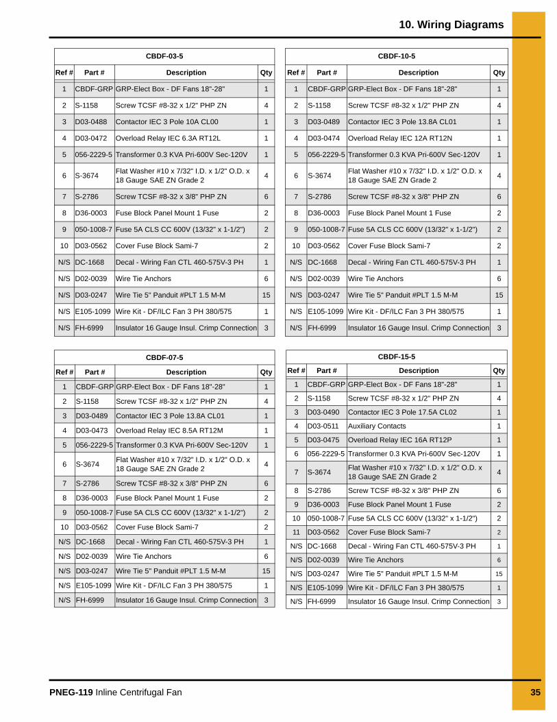
CBDF-03-5
Ref # Part # Description Qty
1 CBDF-GRP GRP-Elect Box - DF Fans 18"-28" 1
2 S-1158 Screw TCSF #8-32 x 1/2" PHP ZN 4
3 D03-0488 Contactor IEC 3 Pole 10A CL00 1
4 D03-0472 Overload Relay IEC 6.3A RT12L 1
5 056-2229-5 Transformer 0.3 KVA Pri-600V Sec-120V 1
6 S-3674 Flat Washer #10 x 7/32" I.D. x 1/2" O.D. x 18 Gauge SAE ZN Grade 2 4
7 S-2786 Screw TCSF #8-32 x 3/8" PHP ZN 6
8 D36-0003 Fuse Block Panel Mount 1 Fuse 2
9 050-1008-7 Fuse 5A CLS CC 600V (13/32" x 1-1/2") 2
10 D03-0562 Cover Fuse Block Sami-7 2
N/S DC-1668 Decal - Wiring Fan CTL 460-575V-3 PH 1
N/S D02-0039 Wire Tie Anchors 6
N/S D03-0247 Wire Tie 5" Panduit #PLT 1.5 M-M 15
N/S E105-1099 Wire Kit - DF/ILC Fan 3 PH 380/575 1
N/S FH-6999 Insulator 16 Gauge Insul. Crimp Connection 3
CBDF-07-5
Ref # Part # Description Qty
1 CBDF-GRP GRP-Elect Box - DF Fans 18"-28" 1
2 S-1158 Screw TCSF #8-32 x 1/2" PHP ZN 4
3 D03-0489 Contactor IEC 3 Pole 13.8A CL01 1
4 D03-0473 Overload Relay IEC 8.5A RT12M 1
5 056-2229-5 Transformer 0.3 KVA Pri-600V Sec-120V 1
6 S-3674 Flat Washer #10 x 7/32" I.D. x 1/2" O.D. x 18 Gauge SAE ZN Grade 2 4
7 S-2786 Screw TCSF #8-32 x 3/8" PHP ZN 6
8 D36-0003 Fuse Block Panel Mount 1 Fuse 2
9 050-1008-7 Fuse 5A CLS CC 600V (13/32" x 1-1/2") 2
10 D03-0562 Cover Fuse Block Sami-7 2
N/S DC-1668 Decal - Wiring Fan CTL 460-575V-3 PH 1
N/S D02-0039 Wire Tie Anchors 6
N/S D03-0247 Wire Tie 5" Panduit #PLT 1.5 M-M 15
N/S E105-1099 Wire Kit - DF/ILC Fan 3 PH 380/575 1
N/S FH-6999 Insulator 16 Gauge Insul. Crimp Connection 3
CBDF-10-5
Ref # Part # Description Qty
1 CBDF-GRP GRP-Elect Box - DF Fans 18"-28" 1
2 S-1158 Screw TCSF #8-32 x 1/2" PHP ZN 4
3 D03-0489 Contactor IEC 3 Pole 13.8A CL01 1
4 D03-0474 Overload Relay IEC 12A RT12N 1
5 056-2229-5 Transformer 0.3 KVA Pri-600V Sec-120V 1
6 S-3674 Flat Washer #10 x 7/32" I.D. x 1/2" O.D. x 18 Gauge SAE ZN Grade 2 4
7 S-2786 Screw TCSF #8-32 x 3/8" PHP ZN 6
8 D36-0003 Fuse Block Panel Mount 1 Fuse 2
9 050-1008-7 Fuse 5A CLS CC 600V (13/32" x 1-1/2") 2
10 D03-0562 Cover Fuse Block Sami-7 2
N/S DC-1668 Decal - Wiring Fan CTL 460-575V-3 PH 1
N/S D02-0039 Wire Tie Anchors 6
N/S D03-0247 Wire Tie 5" Panduit #PLT 1.5 M-M 15
N/S E105-1099 Wire Kit - DF/ILC Fan 3 PH 380/575 1
N/S FH-6999 Insulator 16 Gauge Insul. Crimp Connection 3
CBDF-15-5
Ref # Part # Description Qty
1 CBDF-GRP GRP-Elect Box - DF Fans 18"-28" 1
2 S-1158 Screw TCSF #8-32 x 1/2" PHP ZN 4
3 D03-0490 Contactor IEC 3 Pole 17.5A CL02 1
4 D03-0511 Auxiliary Contacts 1
5 D03-0475 Overload Relay IEC 16A RT12P 1
6 056-2229-5 Transformer 0.3 KVA Pri-600V Sec-120V 1
7 S-3674 Flat Washer #10 x 7/32" I.D. x 1/2" O.D. x 18 Gauge SAE ZN Grade 2 4
8 S-2786 Screw TCSF #8-32 x 3/8" PHP ZN 6
9 D36-0003 Fuse Block Panel Mount 1 Fuse 2
10 050-1008-7 Fuse 5A CLS CC 600V (13/32" x 1-1/2") 2
11 D03-0562 Cover Fuse Block Sami-7 2
N/S DC-1668 Decal - Wiring Fan CTL 460-575V-3 PH 1
N/S D02-0039 Wire Tie Anchors 6
N/S D03-0247 Wire Tie 5" Panduit #PLT 1.5 M-M 15
N/S E105-1099 Wire Kit - DF/ILC Fan 3 PH 380/575 1
N/S FH-6999 Insulator 16 Gauge Insul. Crimp Connection 3

36 PNEG-119 Inline Centrifugal Fan
NOTES
9101239_1_CR_rev7.DOC (revised July 2009)
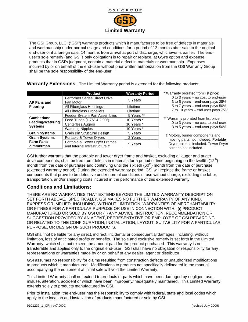
Limited Warranty
The GSI Group, LLC. (“GSI”) warrants products which it manufactures to be free of defects in materials and workmanship under normal usage and conditions for a period of 12 months after sale to the original end-user or if a foreign sale, 14 months from arrival at port of discharge, whichever is earlier. The end-user’s sole remedy (and GSI’s only obligation) is to repair or replace, at GSI’s option and expense, products that in GSI’s judgment, contain a material defect in materials or workmanship. Expenses incurred by or on behalf of the end-user without prior written authorization from the GSI Warranty Group shall be the sole responsibility of the end-user.
Warranty Extensions: The Limited Warranty period is extended for the following products:
Product Warranty Period
AP Fans and Flooring
Performer Series Direct Drive Fan Motor 3 Years
All Fiberglass Housings Lifetime All Fiberglass Propellers Lifetime
Cumberland Feeding/Watering Systems
Feeder System Pan Assemblies 5 Years ** Feed Tubes (1.75" & 2.00") 10 Years * Centerless Augers 10 Years * Watering Nipples 10 Years *
Grain Systems Grain Bin Structural Design 5 Years Grain Systems Farm Fans Zimmerman
Portable & Tower Dryers 2 Years Portable & Tower Dryer Frames and Internal Infrastructure † 5 Years
GSI further warrants that the portable and tower dryer frame and basket, excluding all auger and auger drive components, shall be free from defects in materials for a period of time beginning on the twelfth (12th) month from the date of purchase and continuing until the sixtieth (60th) month from the date of purchase (extended warranty period). During the extended warranty period, GSI will replace the frame or basket components that prove to be defective under normal conditions of use without charge, excluding the labor, transportation, and/or shipping costs incurred in the performance of this extended warranty.
* Warranty prorated from list price: 0 to 3 years – no cost to end-user 3 to 5 years – end-user pays 25% 5 to 7 years – end-user pays 50% 7 to 10 years – end user pays 75% ** Warranty prorated from list price: 0 to 3 years – no cost to end-user 3 to 5 years – end-user pays 50% † Motors, burner components and moving parts not included. Portable Dryer screens included. Tower Dryer screens not included.
Conditions and Limitations: THERE ARE NO WARRANTIES THAT EXTEND BEYOND THE LIMITED WARRANTY DESCRIPTION SET FORTH ABOVE. SPECIFICALLY, GSI MAKES NO FURTHER WARRANTY OF ANY KIND, EXPRESS OR IMPLIED, INCLUDING, WITHOUT LIMITATION, WARRANTIES OF MERCHANTABILITY OR FITNESS FOR A PARTICULAR PURPOSE OR USE IN CONNECTION WITH: (i) PRODUCT MANUFACTURED OR SOLD BY GSI OR (ii) ANY ADVICE, INSTRUCTION, RECOMMENDATION OR SUGGESTION PROVIDED BY AN AGENT, REPRESENTATIVE OR EMPLOYEE OF GSI REGARDING OR RELATED TO THE CONFIGURATION, INSTALLATION, LAYOUT, SUITABILITY FOR A PARTICULAR PURPOSE, OR DESIGN OF SUCH PRODUCTS.
GSI shall not be liable for any direct, indirect, incidental or consequential damages, including, without limitation, loss of anticipated profits or benefits. The sole and exclusive remedy is set forth in the Limited Warranty, which shall not exceed the amount paid for the product purchased. This warranty is not transferable and applies only to the original end-user. GSI shall have no obligation or responsibility for any representations or warranties made by or on behalf of any dealer, agent or distributor.
GSI assumes no responsibility for claims resulting from construction defects or unauthorized modifications to products which it manufactured. Modifications to products not specifically delineated in the manual accompanying the equipment at initial sale will void the Limited Warranty.
This Limited Warranty shall not extend to products or parts which have been damaged by negligent use, misuse, alteration, accident or which have been improperly/inadequately maintained. This Limited Warranty extends solely to products manufactured by GSI.
Prior to installation, the end-user has the responsibility to comply with federal, state and local codes which apply to the location and installation of products manufactured or sold by GSI.
This equipment shall be installed in accordance with the current installation codes and applicable
regulations which should be carefully followed in all cases. Authorities having jurisdiction should be
consulted before installations are made.
GSI Group 1004 E. Illinois St.
Assumption, IL 62510-0020 Phone: 1-217-226-4421
Fax: 1-217-226-4420 www.gsiag.com
Copyright © 2009 by GSI GroupPrinted in the USA