Embed Size (px)
Citation preview

PNEG-4236
36' Diameter (13 Rings and Shorter)
40-Series Bin - 4.00" Corrugation 6000 lb. Peak load Roof with FC Stiffeners
Construction Manual
PNEG-4236Date: 12-29-14

2 PNEG-4236 40-Series 36' Diameter Bin

Table of Contents
PNEG-4236 40-Series 36' Diameter Bin 3
ContentsChapter 1 Safety ..................................................................................................................................................... 5
Safety Guidelines .................................................................................................................................. 5General Safety Statement ..................................................................................................................... 6Safety Instructions ................................................................................................................................. 7Safety Sign-Off Sheet ........................................................................................................................... 9
Chapter 2 Decals .................................................................................................................................................. 10
Chapter 3 General Overview ............................................................................................................................... 13General Information ............................................................................................................................ 13Tools Required for Construction ......................................................................................................... 13Guidelines for Proper Storage of Grain Bin Materials Prior to Construction ....................................... 14Overview for a Typical Bin Installation ................................................................................................ 14Guidelines for Construction Procedures and Lifting Jack Usage ........................................................ 15Instructions for Stirring Devices .......................................................................................................... 16Guidelines for Placement of the Decal Sidewall Sheet ....................................................................... 17
Chapter 4 Foundations ........................................................................................................................................ 18Foundation Recommendations ........................................................................................................... 18Selecting the Proper Site Location ...................................................................................................... 18Scribe the Diameter ............................................................................................................................ 18Foundation Forms ............................................................................................................................... 19Preparing the Foundation Forms ........................................................................................................ 19Placing the Reinforcement .................................................................................................................. 20Anchor Bolt Detail ............................................................................................................................... 20Anchor Bolt Charts .............................................................................................................................. 21Placement of the Vane Axial Fan Foundation ..................................................................................... 22Placement of the Centrifugal Fan Foundation ..................................................................................... 23Floating Monolithic Foundations for Bins (with up to 5 Rings) ............................................................ 24Frost Free Foundation Recommendations .......................................................................................... 25Inverted “T” Foundation (3000 PSF Soil Bearing Capacity) ................................................................ 27
Chapter 5 Hardware Requirements .................................................................................................................... 29Bolt and Nut Pairings .......................................................................................................................... 29Hardware for 2 Post Sidewall Sheets on 4" Corrugation Bins 12' to 60' Diameter .............................. 29Bolt Torque Specifications .................................................................................................................. 30Identifying Bolt Grades ........................................................................................................................ 30Bolt Identification ................................................................................................................................. 31Color Chart for Bin Hardware Bucket Lids .......................................................................................... 34
Chapter 6 Gauge Sheet ....................................................................................................................................... 35Stiffener and Sidewall Gauge Sheet ................................................................................................... 35
Chapter 7 Assembling Sidewall Sheets ............................................................................................................. 36Guidelines for Constructing Sidewall Sheets ...................................................................................... 36Color Codes for Sidewall Gauge Identification .................................................................................... 36Orientation Detail for Top Sidewall Sheets ......................................................................................... 37Caulking and Bolting Detail for Standard Sidewall Sheets .................................................................. 38
Chapter 8 Farm Stiffeners ................................................................................................................................... 40Stiffener Starting Location ................................................................................................................... 40Stiffener Part Number Description ...................................................................................................... 41Color Codes for Stiffener Gauge Identification .................................................................................... 41Top Stiffeners ...................................................................................................................................... 41Standard Stiffeners ............................................................................................................................. 42Stiffeners Splice .................................................................................................................................. 43Base Boot ............................................................................................................................................ 43Base Stiffeners .................................................................................................................................... 441 Ring Top Stiffener (16 Gauge) to a 1 Ring Stiffener (12-16 Gauge) ................................................ 45

Table of Contents
4 PNEG-4236 40-Series 36' Diameter Bin
1 Ring Top Stiffener (16 Gauge) to a 2 Ring Stiffener (12-16 Gauge) ................................................ 452 Ring Top Stiffener (16 Gauge) to a 2 Ring Stiffener (12-16 Gauge) ................................................ 462 Ring Stiffener (10 Gauge) to a 2 Ring Stiffener (8 Gauge) .............................................................. 462 Ring Stiffener (12-16 Gauge) to a 2 Ring Stiffener (12-16 Gauge) .................................................. 472 Ring Stiffener (5-8 Gauge) to a Base Stiffener (5-8 Gauge) ............................................................ 472 Ring Stiffener (10-16 Gauge) to a Base Stiffener (10 Gauge) ......................................................... 482 Ring Stiffener (12-16 Gauge) to a Base Stiffener (12-14 Gauge) .................................................... 482 Ring Stiffener (5-8 Gauge) to a Base Stiffener (5 Gauge) ............................................................... 49Transitional Stiffener (10 Gauge) to a Base Stiffener (8 Gauge) ........................................................ 49Base Stiffener (8 Gauge) to a Base Boot (10 Gauge) ......................................................................... 50Base Stiffener (10-14 Gauge) to a Base Boot (10 Gauge) ................................................................. 50Base Stiffener (5 Gauge) to a Base Boot (10 Gauge) ......................................................................... 51
Chapter 9 Door Assembly ................................................................................................................................... 52Standard Door Placement ................................................................................................................... 522 Ring Door Installation ....................................................................................................................... 53Options for 2 Ring Door - Bin Step ...................................................................................................... 58
Chapter 10 Roof Assembly ................................................................................................................................. 59Roof Assembly Instructions ............................................................................................................... 59Assembling Center Collar .................................................................................................................. 60Assembling the Intermediate Center Collar ....................................................................................... 60Roof Flashing .................................................................................................................................... 61Roof Panel Instructions ..................................................................................................................... 62Installing the Manway Cover ............................................................................................................. 65Roof Ring Locations .......................................................................................................................... 67Installing a Roof Ring ........................................................................................................................ 68Assembling the Auto Roof Vent ......................................................................................................... 70Assembling Wire Grill Guard Roof Vent ............................................................................................ 71Installing the Roof Vents .................................................................................................................... 72
Chapter 11 Accessories ...................................................................................................................................... 73Ladder Section Assembly .................................................................................................................. 73Inside Ladder Placement ................................................................................................................... 74Installing Inside Ladder Bottom Bracket ............................................................................................ 76Guidelines for Installing a Sidedraw System ..................................................................................... 77Wind Ring Requirements ................................................................................................................... 83Installing Wind Rings ......................................................................................................................... 83Temperature Cable Support Package Instructions for Eave Heights of 40'-5" (12.32 m) or Less (Optional) ......................................................................... 85Temperature Cable Support Package Instructions (for Eave Heights Greater than 40'-5" (12.32 m)) (Optional) ............................................................. 86Assembling Weather Cover for Roller Valve ..................................................................................... 89Transition Assembly .......................................................................................................................... 90Seal Kit (Optional) ............................................................................................................................. 91
Chapter 12 Warranty ............................................................................................................................................ 93
PNEG-4236 40-Series 36' Diameter Bin 5
1. Safety
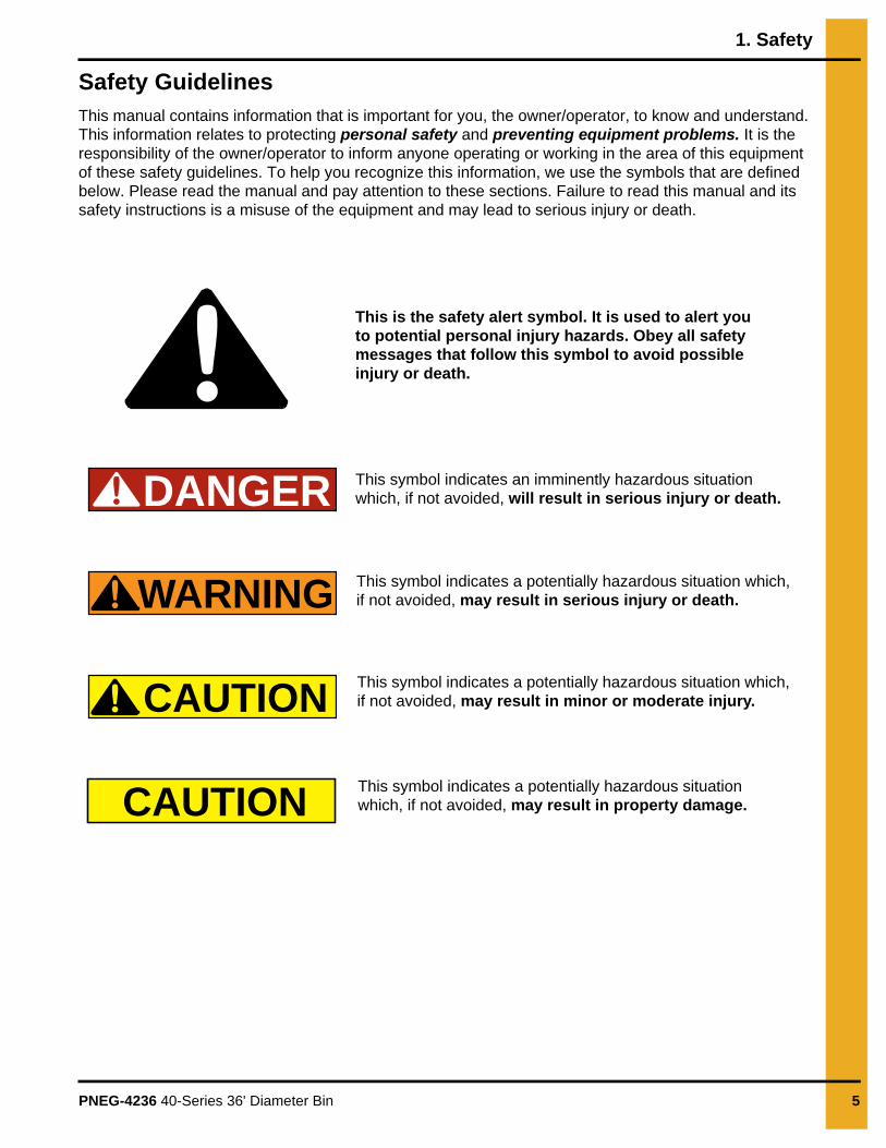
Safety GuidelinesThis manual contains information that is important for you, the owner/operator, to know and understand. This information relates to protecting personal safety and preventing equipment problems. It is the responsibility of the owner/operator to inform anyone operating or working in the area of this equipment of these safety guidelines. To help you recognize this information, we use the symbols that are defined below. Please read the manual and pay attention to these sections. Failure to read this manual and its safety instructions is a misuse of the equipment and may lead to serious injury or death.
DANGER
WARNING
CAUTION
CAUTION
This is the safety alert symbol. It is used to alert you to potential personal injury hazards. Obey all safety messages that follow this symbol to avoid possible injury or death.
This symbol indicates a potentially hazardous situation which, if not avoided, may result in serious injury or death.
This symbol indicates a potentially hazardous situation which, if not avoided, may result in minor or moderate injury.
This symbol indicates a potentially hazardous situation which, if not avoided, may result in property damage.
This symbol indicates an imminently hazardous situation which, if not avoided, will result in serious injury or death.

1. Safety
6 PNEG-4236 40-Series 36' Diameter Bin
General Safety StatementOur foremost concern is your safety and the safety of others associated with grain handling equipment. This manual is to help you understand safe operating procedures and some problems that may be encountered by the operator and other personnel.
As owner and/or operator, you are responsible to know what requirements, hazards, and precautions exist and inform all personnel associated with the equipment or in the area. Safety precautions may be required from the personnel. Avoid any alterations to the equipment, which may produce a very dangerous situation, where SERIOUS INJURY or DEATH may occur.
You should consider the location of the bin site relative to power line locations or electrical transmission equipment. Contact your local power company to review your installation plan or for information concerning required equipment clearance. Clearance of portable equipment that may be taken to the bin site should also be reviewed and considered. Any electrical control equipment in contact with the bin should be properly grounded and installed in accordance with National Electric Code provisions and other local or national codes.
This product is intended for the use of grain storage only. Any other use is a misuse of the product.
Sidewall bundles or sheets must be stored in a safe manner. The safest method of storing sidewall bundles is laying horizontally with the arch of the sheet upward, like a dome. Sidewall sheets stored on edge must be secured so that they cannot fall over and cause injury. Use care when handling and moving sidewall bundles.
Personnel operating or working around equipment should read this manual. This manual must be delivered with equipment to its owner. Failure to read this manual and its safety instructions is a misuse of the equipment.
This product has sharp edges, which may cause serious injury. To avoid injury, handlesharp edges with caution and always use proper protective clothing and equipment.
1. Safety
PNEG-4236 40-Series 36' Diameter Bin 7
Safety Instructions
Our foremost concern is your safety and the safety of others associated with this equipment. We want to keep you as a customer. This manual is to help you understand safe operating procedures and some problems that may be encountered by the operator and other personnel.
As owner and/or operator, it is your responsibility to know what requirements, hazards, and precautions exist, and to inform all personnel associated with the equipment or in the area. Safety precautions may be required from the personnel. Avoid any alterations to the equipment. Such alterations may produce a very dangerous situation where SERIOUS INJURY or DEATH may occur.
This equipment shall be installed in accordance with the current installation codes and applicable regulations, which should be carefully followed in all cases. Authorities having jurisdiction should be consulted before installations are made.
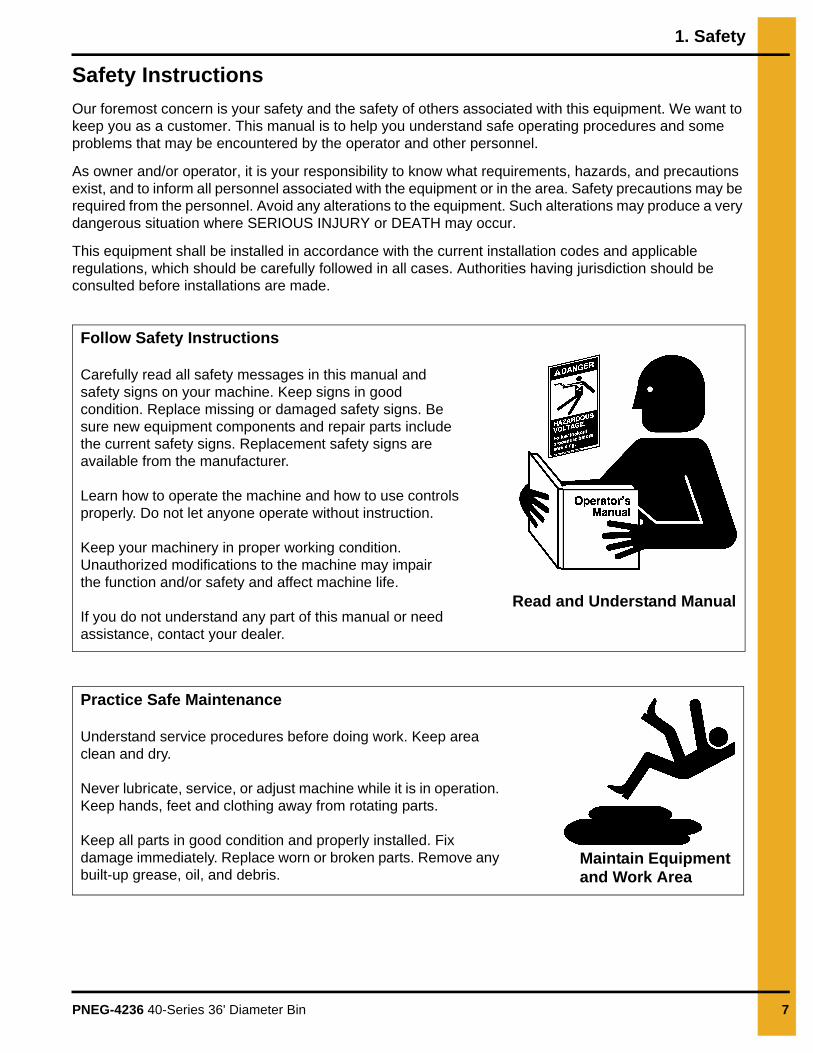
Follow Safety Instructions
Carefully read all safety messages in this manual and safety signs on your machine. Keep signs in good condition. Replace missing or damaged safety signs. Be sure new equipment components and repair parts include the current safety signs. Replacement safety signs are available from the manufacturer.
Learn how to operate the machine and how to use controls properly. Do not let anyone operate without instruction.
Keep your machinery in proper working condition. Unauthorized modifications to the machine may impair the function and/or safety and affect machine life.
If you do not understand any part of this manual or need assistance, contact your dealer.
Read and Understand Manual
Practice Safe Maintenance
Understand service procedures before doing work. Keep area clean and dry.
Never lubricate, service, or adjust machine while it is in operation. Keep hands, feet and clothing away from rotating parts.
Keep all parts in good condition and properly installed. Fix damage immediately. Replace worn or broken parts. Remove any built-up grease, oil, and debris.
Maintain Equipment and Work Area

1. Safety
8 PNEG-4236 40-Series 36' Diameter Bin
Prepare for Emergencies
Be prepared if fire starts.
Keep a first aid kit and fire extinguisher handy.
Keep emergency numbers for doctors, ambulance service, hospital, and fire department near your telephone.
Keep Emergency Equipment Quickly Accessible
Wear Protective Clothing
Wear close-fitting clothing and safety equipment appropriateto the job.
Remove all jewelry.
Tie long hair up and back.
Wear safety glasses at all times to protect eyes from debris.
Wear gloves to protect your hands from sharp edges on plastic or steel parts.
Wear steel-toed boots to help protect your feet from falling debris. Tuck in any loose or dangling shoestrings.
A respirator may be needed to prevent breathing potentially toxic fumes and dust.
Wear a hard hat to help protect your head.
Wear appropriate fall protection equipment when working at elevations greater than six feet (6').
Eye Protection
Gloves
Steel-Toed Boots
Respirator
Hard Hat
Fall Protection

1. Safety
PNEG-4236 40-Series 36' Diameter Bin 9
Safety Sign-Off Sheet
As a requirement of O.S.H.A., it is necessary for the employer to train the employee in the safe operating and safety procedures for this equipment. This sign-off sheet is provided for your convenience and personal record keeping. All unqualified persons are to stay out of the work area at all times. It is strongly recommended that another qualified person who knows the shut down procedure be in the area in the event of an emergency.
Date Employee Name Supervisor Name

10 PNEG-4236 40-Series 36' Diameter Bin
2. Decals
The manufacturer does not warrant any roof damage caused by excessive vacuum or internal pressure from fans or other air moving systems. Adequate ventilation and/or “makeup air” devices should be provided for all powered air handling systems. The manufacturer does not recommend the use of downward flow systems (suction). Severe roof damage can result from any blockage of air passages. Running fans during high humidity/cold weather conditions can cause air exhaust or intake ports to freeze.
Excessive vacuum (or pressure) may damage roof. Use positive aeration system. Make sure all roof vents are open and unobstructed. Start roof fans when supply fans are started. Do not operate when conditions exist that may cause roof vent icing.
DC-969
CAUTION
GSI Group, Inc. 217-226-4421

2. Decals
PNEG-4236 40-Series 36' Diameter Bin 11
ATTENTION: The decal shown below should be present on the outside of the door cover of the 2 ring, 24" porthole door cover and roof manway cover. If a decal has been damaged or is missing in any of these locations, contact the manufacturer for a free replacement decal.
GSI Decals1004 E. Illinois St.Assumption, IL. 62510Phone: 1-217-226-4421
Rotating flighting willkill or dismember.
Flowing material willtrap and suffocate.
Crusted material willcollapse and suffocate.
DANGER
Keep clear of all augers.DO NOT ENTER this bin!
If you must enter the bin:1. Shut off and lock out all power.2. Use a safety harness and safety line.3. Station another person outside the bin.4. Avoid the center of the bin.5. Wear proper breathing equipment or respirator.
Failure to heed thesewarnings will result inserious injury or death.
DC-GBC-1AGSI GROUP, INC. 217-226-4421

2. Decals
12 PNEG-4236 40-Series 36' Diameter Bin
ATTENTION: The decal shown below should be present on the outside of the door cover of the 2 ring, 24" porthole door cover and roof manway cover. If a decal has been damaged or is missing in any of these locations, contact the manufacturer for a free replacement decal.
GSI Decals1004 E. Illinois St.Assumption, IL. 62510Phone: 1-217-226-4421
WARNING
GSI GROUP, INC. 217-226-4421
1. Use CENTER FLOOR OUTLET ONLY until NO grain remains above this outlet.2. Side floor outlets to be used ONLY when above condition is satisfied.3. Lock all side floor outlets to avoid accidental premature use.4. See manufacturers instructions for proper use of factory supplied sidedraw (wall) discharge systems.
UNLOADING INSTRUCTIONS:
Failure to heed these warningscould result in serious injury, death,
structural damage or collapse of tank.DC-GBC-2A

PNEG-4236 40-Series 36' Diameter Bin 13
3. General Overview
General Information
General information, overview and instructions needed before performing work.
Read this manual carefully. This manual will provide instructions on building the sidewall and stiffeners. You will also need to consult other instructions in building the bin.
These include, but may not be limited to:
1. A stiffener and sidewall gauge layout chart. If such a chart is not included with this manual, contact GSI.
2. Roof instructions must be followed. Roof instructions are included in this manual.
3. Ladders, roof stairs, roof handrails and other products are covered by separate instruction manuals. Consult the appropriate accessory manual. Inside ladder instructions are included in this manual.
4. Aeration systems and transitions are to be installed according to the instructions provided with the system or transition.
5. It is critical that the anchor bolts are installed and spaced correctly.
Tools Required for ConstructionGeneral tools needed to perform this construction:
1. Combination wrench set 7/16" to 1".
2. Alignment punches 12" long.
3. 1/2" Drive socket set and ratchet.
4. Nail aprons or tool pouches to hold supplies.
5. Gloves for hand protection.
6. Tape measure.
7. 1/2" Drive electric or pneumatic torque gun with variable impact capabilities.
8. 1/2" Drive impact socket set.
9. Lifting jacks.
10. Center pole roof support.
11. Step ladders.
12. Large C-clamp or welding V-grip for clamping.
NOTE: Quantities required will depend on the number of workers and size of the bin.

3. General Overview
14 PNEG-4236 40-Series 36' Diameter Bin
Guidelines for Proper Storage of Grain Bin Materials Prior to Construction
Storage of the build materials prior to construction is important. Do not to allow moisture to remain between sheets or panels.
Wet storage stain (rust) will develop when closely packed bundles of galvanized material, such as sidewall and roof sheets, have moisture present. Inspect roof and sidewall bundles on arrival for any moisture. If moisture is present, it must not be allowed to remain between the sheets. Separate the sheets or panels immediately and wipe them down. Spray with a light oil or diesel fuel.
If possible, sidewall bundles, roof sheets and other closely packed galvanized materials should be stored in a dry, climate controlled building. If outdoor storage is unavoidable, the materials should be stored so that they are raised above the ground and vegetation. Any stacking and spacing materials should not be corrosive or wet. Be sure to protect materials from the weather, but permit air movement around the bundles if possible.
Storing roof bundles and sidewall sheets at a slight incline can also help minimize the presence of moisture. Storing the bundles with the center of the dome up (like an arch) is one option for minimizing moisture during storage. Sidewall bundles can also be stored on edge but must be secured so that they do not fall over and cause injury.
If “white rust” or “wet storage stain” occurs, contact the manufacturer immediately about ways to minimize the adverse effect upon the galvanized coating.
Overview for a Typical Bin InstallationThese are the typical steps one would perform when constructing a grain bin. Procedures may vary depending on site requirements.
Pre-Assembly Activities
1. Sorting and grouping parts.
Assembly
1. For 36' bins, build 2 rings of sidewall sheets for even ringed bins or one ring for odd ringed bins and 12 rings, making sure to caulk all seams.
2. Install wind ring to help support the rings.
3. Install the center collar tower support in the center of the bin.
4. Install eave clips and intermediate eave angles to the sidewall sheets. (Note how these are aligned.)
5. Install roof panels.
6. Install roof flashing.
7. Install peak cap.

3. General Overview
PNEG-4236 40-Series 36' Diameter Bin 15
Guidelines for Construction Procedures and Lifting Jack Usage
The following procedure is a guideline when using the required lifting jack. Follow this general guideline when lifting the bin as sidewalls are being installed.
NOTE: The roof and the top ring for odd ringed bins or the roof and 2 rings for even ringed bins, will be installed prior to the beginning of bin lifting procedures. Refer to all other procedures on sidewall and stiffener installation prior to the start of construction.
IMPORTANT: Begin building with the bin oriented for doors and material handling equipment to be in the correct position when bin construction is complete.
1. Consider the starting location of the bin, relative to the location of doors and other accessories. Proper placement of lifting jacks in relationship to anchor bolts could make a difference in final locations. Note that the sidewall sheets will be staggered.
2. The bin is lifted by the use of lifting jacks. Lifting jacks are used to slowly and evenly lift the bin during construction. Lifting jacks must be properly sized and designed to carry all loads and job site conditions associated with the construction of the bin.
The number of lifting jacks required is best determined by personal experience and expertise. Factors such as bin size, jack design, construction conditions, support surface, etc., are all to be considered when deciding how many to use. If in doubt, use one jack on every sheet. The lifting jack must be adequate to carry all loads. Heavy duty jacks, generally hydraulic or electric powered in the case of large bins, should be used for commercial installation. All jacks should be secured with braces or otherwise maintained in a stable condition.
Lifting of the bins should not be done under windy conditions.
Follow the jack manufacturers recommendations on capacity and operations.
3. Lifting brackets should be attached through the stiffener bolt holes. Normally you will need to attach to at least four (4) bolts per stiffener.
4. Raise the bin just high enough to assemble the next ring. When lifting the bin, all jacks must lift at an equal rate. Monitor the lift to ensure even lifting is occurring.
5. To the inside of the first ring, bolt the next ring. Be sure to stagger the sheets and select the proper gauge material.
6. Lower the bin onto the foundation after assembling and tightening bolts on the new ring or rings.
7. Attach stiffeners to the body sheets every two (2) tiers (on the external surface of the bin). You may want to leave sheets loose to make the attachment of the stiffeners easier.
8. Now re-bolt the lifting brackets to the lowest ring in place thus far. Continue ring additions by repeating Step 5 and Step 6.
9. Add inside and outside ladders as you continue to raise the bin. (Refer to manual supplied with the ladder.)
10. Add platforms as you raise the bin. (Refer to manual supplied with the ladders and platforms.)
11. Lower the tank and secure to the foundation before leaving the job site.
12. At the completion of the tank, set stiffeners over the anchor bolts and measure the tank to ensure it is in a round condition. Consult with GSI for questions on tolerances.

3. General Overview
16 PNEG-4236 40-Series 36' Diameter Bin
Instructions for Stirring DevicesBins are offered in more than one structural series for specific uses. To maintain the warranty, the appropriate “series” grain bin must be used. Consult the sales catalog or contact the Engineering Department for current recommendations. Note that the use of any stirring device with three (3) or more vertical screws may require a heavier than “standard” series bin. Any re-circulating device or system should be used in the “re-circulating” series bins. NOTE: For GSI bins larger than 36' diameter an alternate method of mounting is to attach suspension chain to intermediate center collar.
1. Read owner’s manual for the stirring device and follow all instructions set forth by the manufacturer.
IMPORTANT: Install the switch for the stirring device near the roof manway opening so that the unit can be observed while stirring.
2. Make sure there are no obstructions, such as protruding ladders.
3. After loading approximately 3' of grain, run the unit one complete revolution to determine if it is working properly.
4. If the unit is functioning properly, operate the stirring device continuously while filling and drying to avoid compacted grain around the vertical screws.
5. If it becomes necessary to stop a stirring device using laterally moving screws, try to stop it with the vertical screws nearest to the center of the bin, away from the sidewall. Should a device stop or stall for any reason and remain inoperable for any length of time, the auger carriage should be supported to the grain surface before restarting. The vertical auger should be turned by hand, with a pipe wrench, before power is applied.
6. For best results, fill the bin to one-half of the final intended depth. Dry grain to 16% and continue filling. Use filling rates specified by stirring device manufacturer. If necessary to fill to the top without stopping, reduce the filling rate and drying air temperature so that the stirring rate can keep up with the drying rate.
7. Do not overfill bin. Filling should be stopped at bottom of top ring or 30" below the track.
NOTE: The above steps are only general instructions which apply to the majority of stirring devices. Since there are different manufacturers of these devices, it is important to read the operator’s manual thoroughly for specific instructions applicable to the machine.
Stirring devices may create additional loads on grain bin sidewalls, roofs and floors. If high-moisture grain is loaded too deep and too fast, unstiffened bin walls can become overloaded. Observe the following installation and operation procedures if the bin is to be equipped with the stirring device.
WARNING

3. General Overview
PNEG-4236 40-Series 36' Diameter Bin 17
Guidelines for Placement of the Decal Sidewall SheetUse the following as a general guideline the proper decal sheet placement.
NOTE: Refer to stiffener to sidewall attachment detail and specific gauge sheet for the bin. The decal sheets are located in the first ring from the top. They are to be spaced evenly around the diameter of the bin.
Figure 3A Decal Sidewall Sheet
NOTE: Highlighted lines represent stiffener locations.

18 PNEG-4236 40-Series 36' Diameter Bin
4. Foundations
Foundation RecommendationsThese are general foundation recommendations. Site conditions, system requirements and other factors may create foundation construction requirements not covered by this manual.
Selecting the Proper Site Location
1. The selected site should be level, firm and free from underlying debris. The soil bearing capacity should be equal to or greater than required by the footing specifications.
2. The concrete foundation surface must be level. If fill is required, it should be watered and tamped thoroughly to prevent uneven settling from the weight of the bin.
3. The site should allow easy access for easy loading and unloading, as well as provide additional space for future units.
4. When selecting a bin site, also consider the positioning of handling equipment, fans, heaters, fuel lines and the availability of electricity.
Scribe the Diameter
1. Determine the center of the foundation site and drive a small 2 x 4 into the ground to mark it. Drive the stake into the ground so that it is the same height as the finished foundation will be.
2. Using one large spike, nail a straight 2 x 4 to the top of the center spike. This 2 x 4 should be approximately two feet (2') longer than the radius of the bin. The swiveling 2 x 4 will act as a compass, enabling you to scribe the correct diameter of the foundation and later locate the anchor and stiffener bolt locations. (See Figure 4A.)
NOTE: Making the 2 x 4 two feet (2') longer than the radius will allow the 2 x 4 to also be used as a leveling device and for pulling concrete.
Figure 4A Scribe the Diameter
Ref # Description Ref # Description
A Spike D Pointed Stake
B Foundation Radius E Foundation Line
C 2' F 2 x 4 Center Stake

4. Foundations
PNEG-4236 40-Series 36' Diameter Bin 19
Foundation Forms
Circular foundation forms are commonly used for stiffened farm bins.
Figure 4B Circular Form
Preparing the Foundation Forms1. Having scribed the diameter of the foundation, proceed by digging the foundation’s footing, which
consists of a large circular trench inside the foundation line.
2. Once the footing has been dug, you are ready to build the forms. The forms must be rigid enough to hold their shape against the poured concrete.
3. The foundation must be flat. Sloped floors cannot be used in drying bins. A carpenter’s level placed on top of the compass 2 x 4 constructed earlier will enable you to set the top of the forms to match the top of the center stake.
4. Check the form work with a transit to ensure a uniform elevation for the entire foundation. The foundation should be level within 1/8" on non-stiffened tanks and within 1/4" on stiffened tanks at bin wall perimeter. Stiffened tanks must be shimmed level. Provisions for unloading system trenches, air ducts, etc., should be made as required by the particular material handling system used.
NOTE: All foundation specifications shall be construed as recommendations only. Because of the many variable conditions in an actual installation, manufacturer assumes no liability for results arising from the use of such recommendations.
Ref # Description
A Footing Trench
B Carpenter’s Level
A
B

4. Foundations
20 PNEG-4236 40-Series 36' Diameter Bin
Placing the Reinforcement
1. Once the forms and trench have been prepared, begin placing the reinforcement rods and mesh in the foundation’s footing. Make sure the reinforcement rods are properly lapped by wiring.
2. Place at least 2" of compacted sand on the inside section of the foundation to provide a good base for the concrete and to protect against rodents.
3. Cover the sand with 4 ml. polyethylene plastic, which will act as a moisture barrier.
4. Add two (2) layers of 6" x 6" wire mesh to the entire area of the foundation slab or the entire foundation for monolithic systems to complete the preparation of the bin’s foundation.
Anchor Bolt Detail
The following is the minimum requirement for anchoring of standard tanks. Refer to sidedraw instructions for special anchoring details.
1. 5/8" Diameter anchor bolt (A) is the minimum allowed, 3/4" diameter anchor bolt (A) is the minimum with sidedraw flume system.
2. Exposed anchor bolt thread height (B) for 5/8" and 3/4" diameter anchor bolts are 3" (7.6 cm) and 5" (12.7 cm) respectively.
3. Overall anchor bolt length (C) for 5/8" and 3/4" diameter anchor bolts are 14" (35.56 cm) and 18" (45.72 cm) respectively. (See Figure 4C.)
Figure 4C Anchor Bolt Example (3/4" Diameter Anchor Bolt Shown)
Ref # Description
A Anchor Bolt
B Anchor Bolt Thread Height
C Anchor Bolt Length
4. Foundations
PNEG-4236 40-Series 36' Diameter Bin 21
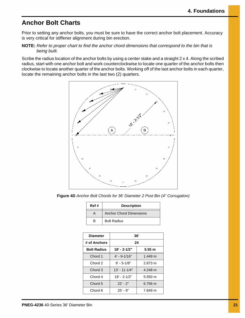
Anchor Bolt Charts
Prior to setting any anchor bolts, you must be sure to have the correct anchor bolt placement. Accuracy is very critical for stiffener alignment during bin erection.
NOTE: Refer to proper chart to find the anchor chord dimensions that correspond to the bin that is being built.
Scribe the radius location of the anchor bolts by using a center stake and a straight 2 x 4. Along the scribed radius, start with one anchor bolt and work counterclockwise to locate one quarter of the anchor bolts then clockwise to locate another quarter of the anchor bolts. Working off of the last anchor bolts in each quarter, locate the remaining anchor bolts in the last two (2) quarters.
Figure 4D Anchor Bolt Chords for 36' Diameter 2 Post Bin (4" Corrugation)
Ref # Description
A Anchor Chord Dimensions
B Bolt Radius
Diameter 36'
# of Anchors 24
Bolt Radius 18' - 2-1/2" 5.55 m
Chord 1 4' - 9-1/16" 1.449 m
Chord 2 9' - 5-1/8" 2.873 m
Chord 3 13' - 11-1/4" 4.248 m
Chord 4 18' - 2-1/2" 5.550 m
Chord 5 22' - 2" 6.756 m
Chord 6 25' - 9" 7.849 m

4. Foundations
22 PNEG-4236 40-Series 36' Diameter Bin
Placement of the Vane Axial Fan Foundation
If a fan or fan and heater combination is to be installed, determine the concrete foundation size.
1. The top of the fan foundation should be level with the top of the bin’s foundation.
2. Recommended foundation thickness is 4" minimum.
3. The front of the foundation should be perpendicular to the bin wall.
4. Concrete foundation for the heater is not required. If it is to be added, pour the concrete to cover the locations of both the heater and the fan. (See Figure 4E.)
Figure 4E Vane Axial Fan Foundation
Ref # Description
B Fan Foundation
C Bin Center
D Bin Wall
TransitionDistance between Fan Foundation and Bin Wall (A) for Fans without Heaters
(in.)
Distance between Fan Foundationand Bin Wall (A) for Fans with Heaters
(in.)
TR-4734 20 44
TR-6918 and TR-6919 32 55
TR-7048 45 69
TR-8006 46 70
CAUTION
The foundation and fan must be level and smooth for proper operation. Improperleveling can cause vibration problems.

4. Foundations
PNEG-4236 40-Series 36' Diameter Bin 23
Placement of the Centrifugal Fan Foundation
1. A correct fan foundation should be poured 2" below the top of bin foundation for all centrifugal fans.
2. A foundation for heaters is not required, but is recommended.
3. Recommended foundation thickness is 4".
4. If a downwind heater foundation is to be installed, the foundation width (F) should be 48" and extended towards the bin by 33".
5. The Fan discharge should be centered on the centerline of the bin.
6. The fan foundation should be perpendicular to the bin wall. (See Figure 4F.)
Figure 4F Centrifugal Fan Foundation
Ref # Description
B Fan Foundation
C Bin Center
D Bin Wall
TransitionDistance between Fan
Foundation and Bin Wall (A) for Fans without Heaters (in.)
Distance between Fan Foundation and Bin Wall (A) for
Fans with Heaters (in.)E (in.) F (in.) G (in.)
TR-4734 20 44 10 40 40TR-7048 45 - 10 40 48TR-6918 and TR-6919 32 65 13 48 52TR-7049 45 78 13 48 52TR-6207 42 75 13 48 60TR-6958 (Double Inlet) 55 85 13 48 60TR-6853 (Double Inlet) 54 88 28 100 60
CAUTION
The fan foundation and fan must be level and smooth for proper operation. Improper leveling can cause vibration problems.

4. Foundations
24 PNEG-4236 40-Series 36' Diameter Bin
Floating Monolithic Foundations for Bins (with up to 5 Rings)The foundation design is based on a minimum allowable soil bearing capacity 3000 PSF. Bearing capacity of the soil should be determined by geotechnical investigation and be of uniform bearing capacity.
1. All reinforcement must meet the requirements of ASTM A615 grade 60 deformed bars.
2. Concrete must have a minimum compressive strength of 4000 PSI at 28 days, 6% to 8% air entrainment and 4" slump.
3. The foundation site must be free of vegetation and debris and well drained.
4. The foundation must be founded below the frost line or placed on non expansive frost free fill.
5. Lap all circumferential bars 35 bar diameters and stagger all laps in plans 3'.
NOTE: Estimates do not include end laps.
6. All material used for backfill inside the ring wall should be clean, well graded, crushed rock or a sand and gravel mixture. Backfill should be placed in 6" lifts, 95% compaction. (See Figure 4G.)
Figure 4G Floating Monolithic Foundations
NOTE: All foundation specifications are recommendations only. Due to many variable conditions in actual installation, the manufacturer assumes no liability for results arising from the use of such recommendations.
NOTE: Make sure to contact the manufacturer’s engineering department for additional information for heights more than 6".
NOTE: The optional #4 rebar grid can be substituted for the wire mesh in most cases. Place the #4 bars in the foundation at 18" center to center each way.
Ref # Description Ref # Description
A Outside Radius F 2 - #6 Bars
B Anchor Bolt Circle Radius G Grade
C Two Layers 6 x 6 - 6/6 Wire Mesh H 1'-0" Minimum
D Vapor Barrier I 6" Maximum
E Well Compacted Fill
Bin Diameter
OutsideRadius
Anchor BoltRadius
Anchor Chord
# ofAnchors
Total Cu. Yds.Concrete
Sq. Ft.Mesh
Length #6 Bar (ft.)
Optional #4Grid (ft.)
36' 18'-9" 18' - 2-1/2" 4' - 9-1/16" 24 25 2300 300 1500

4. Foundations
PNEG-4236 40-Series 36' Diameter Bin 25
Frost Free Foundation Recommendations
The foundation design is based on a minimum allowable soil bearing capacity 3000 PSF. Bearing capacity of the soil should be determined by geotechnical investigation and be of uniform bearing capacity.
1. All reinforcement must meet the requirements of ASTM A615 grade 60 deformed bars.
2. Concrete must have a minimum compressive strength of 4000 PSI at 28 days, 6% to 8% air entrainment and 4" slump.
3. The foundation site must be free of vegetation and debris and well drained.
4. The foundation must be founded below the frost line or placed on non expansive frost free fill.
5. Lap all circumferential bars 35 bar diameters and stagger all laps in plans 3'.
NOTE: Estimates do not include end laps.
6. All material used for backfill inside the ring wall should be clean, well graded, crushed rock or a sand and gravel mixture. Backfill should be placed in 6" lifts, 95% compaction. (See Figure 4H.)
Figure 4H Frost Free Foundation
Ref # Description
A Outside Radius
B 1/2" Expansion Joint
C Two (2) Layers 6 x 6 - 6/6 Wire Mesh
D Vapor Barrier
E Well Compacted Fill
F “N” #6 Bars Evenly Spaced
G #6 Bars at 12" c/c Required Only if “B” is Greater than 2'-0"
H 3" Cl.
I 1'-0" Minimum
J Grade
K 6" Maximum

4. Foundations
26 PNEG-4236 40-Series 36' Diameter Bin
NOTE: All foundation specifications are recommendations only. Due to many variable conditions in actual installation, the manufacturer assumes no liability for results arising from the use of such recommendations.
NOTE: Make sure to contact the manufacturer’s engineering department for additional information for heights more than 6".
NOTE: The optional #4 rebar grid can be substituted for the wire mesh in most cases. Place the #4 bars in the foundation at 18" center to center each way.
Specifications for 36' Diameter Bin
Ring B NOutsideRadius
Sq. Ft. Mesh
Optional 18" x 18"Grid (ft.)
Length #6 Bar (ft.)
Total Cu.Yds.Concrete
6 1'-3" 2 18'-9" 2000 1300 300 26
7, 8 2'-0" 2 18'-11" 2000 1300 400 30
9, 10 2'-10" 3 19'-0" 2000 1300 600 33
11, 12 3'-11" 4 19'-6" 2000 1300 900 39
13 4'-10" 5 19'-9" 2000 1300 1100 43

4. Foundations
PNEG-4236 40-Series 36' Diameter Bin 27
Inverted “T” Foundation (3000 PSF Soil Bearing Capacity)
1. Determine bearing capacity of soils by using geotechnical investigations. Found all footings on soils of uniform bearing capacity.
2. All bins with a diameter of 60' or larger must use ASTM A615 grade 60 deformed bars for concrete reinforcement. Bins with a diameter less than 60' must use ASTM A615 grade 40 deformed bars.
3. Concrete must have a minimum compressive strength of 4000 PSI at 28 days.
4. The foundation site should be free of vegetation and debris and be well drained.
5. The foundation must be founded below the frost line or founded on non-frost susceptible soils.
6. Lap all circumferential bars 35 bar diameters and stagger all laps in plans 3'.
NOTE: Estimates do not include end laps.
7. All material used for backfill inside the ring wall should be a clean, well graded, crushed rock or a sand and gravel mixture. Backfill should be placed in 6" lifts, 95% compaction. (See Figure 4I on Page 27.)
Figure 4I Inverted “T” Foundation
Ref # Description Ref # Description
A #4 Bars at 18" c/c Each Way F “P” Bars Spacing at Center of Footing
B 1/2" Expansion Joint G #4 Bars at 12" c/c Each Face (Overall Length = 63")
C Vapor Barrier H Grade
D Well Compacted Fill I “N” #5 Bars Spaced Evenly
E “M” Bars Spaced Evenly Each Face J 4'-0" or Below Frost Line, use Greater Value
4. Foundations
28 PNEG-4236 40-Series 36' Diameter Bin
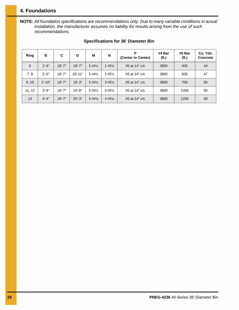
NOTE: All foundation specifications are recommendations only. Due to many variable conditions in actual installation, the manufacturer assumes no liability for results arising from the use of such recommendations.
Specifications for 36' Diameter Bin
Ring B C D M NP
(Center to Center)#4 Bar
(ft.)#5 Bar
(ft.)Cu. Yds.Concrete
6 1'-4" 18'-7" 18'-7" 5 #4’s 2 #5’s #5 at 14" c/c 3800 400 44
7, 8 2'-0" 18'-7" 18'-11" 5 #4’s 2 #5’s #5 at 14" c/c 3800 500 47
9, 10 2'-10" 18'-7" 19'-3" 5 #4’s 3 #5’s #5 at 14" c/c 3800 700 50
11, 12 3'-9" 18'-7" 19'-8" 5 #4’s 4 #5’s #5 at 14" c/c 3800 1000 55
13 4'-4" 18'-7" 20'-3" 5 #4’s 4 #5’s #5 at 14" c/c 3800 1200 58

PNEG-4236 40-Series 36' Diameter Bin 29
5. Hardware Requirements
Bolt and Nut Pairings
This chart lists the correct nut to use with each size of bolt.
Hardware for 2 Post Sidewall Sheets on 4" Corrugation Bins 12' to 60' Diameter
Refer to chart for hardware requirements for 2 post sidewall sheet connections on bins 12' to 60' diameter.
Nut Part # Nut Size Type Hex or Flanged Bolt Size Bolt Part #
S-396 5/16" YDPHex
5/16" x 3/4" S-7482
5/16" x 1-1/4" S-7483
Flanged 5/16" x 1" S-10260
S-3611 5/16" YDP Flanged
5/16" x 3/4" S-7482
5/16" x 1" S-10260
5/16" x 1-1/4" S-7483
S-10268 5/16" JSHex 5/16" x 1-1/4" S-7483
Flanged 5/16" x 1" S-10260
S-456 3/8" YDP Hex 3/8" x 1" S-7487
S-9426 3/8" JSFlanged 3/8" x 1" S-7485
Hex 3/8" x 1" S-7487
S-9281 7/16" JS Hex 7/16" x 3-1/4" S-10261
GaugeHorizontal Seam
Bolt Size (Quantity)Vertical Seam Bolt
Size (Quantity)*Stiffener to SidewallBolt Size (Quantity)
Overlap Seam BoltSize (Quantity)
20 5/16" x 1" (10) 5/16" x 1" (42) 5/16" x 1" (20) 5/16" x 1" (2)
19 5/16" x 1" (10) 5/16" x 1" (42) 5/16" x 1" (20) 5/16" x 1" (2)
18 5/16" x 1" (10) 5/16" x 1" (42) 5/16" x 1" (20) 5/16" x 1" (2)
17 5/16" x 1" (10) 5/16" x 1" (42) 5/16" x 1" (20) 5/16" x 1" (2)
16 5/16" x 1" (10) 5/16" x 1" (42) 5/16" x 1" (20) 5/16" x 1" (2)
15 5/16" x 1" (10) 5/16" x 1" (42) 5/16" x 1" (20) 5/16" x 1" (2)
14 5/16" x 1" (22) 5/16" x 1" (42) 5/16" x 1" (20) 5/16" x 1" (2)
13 3/8" x 1" (22) 3/8" x 1" (42) 5/16" x 1" (20)* 3/8" x 1" (2)
12 3/8" x 1" (22) 3/8" x 1" (42) 5/16" x 1" (20)* 3/8" x 1" (2)
11 3/8" x 1" (22) 3/8" x 1" (42) 5/16" x 1" (20)* 3/8" x 1" (2)
10 3/8" x 1" (22) 3/8" x 1" (42) 5/16" x 1" (20)* 3/8" x 1" (2)
*Use 5/16" x 1-1/4" for all splice/stiffener to sidewall connections and with all 5 gauge stiffener to sidewall connections.

5. Hardware Requirements
30 PNEG-4236 40-Series 36' Diameter Bin
Bolt Torque SpecificationsThe specification torque table below will help the installer determine how tight a specific bolt must be. A bolt that has been over tightened can be just as dangerous as one that has not been tightened enough.
IMPORTANT: Bolts should not be tightened in excess of the torque specifications chart listed below.
Identifying Bolt GradesBolts are identified by grade (or hardness), the grade can be identified by the markings on the head of the bolt. These markings will be in the form of slash marks and patterns. Use the following as a guide to determine the correct bolt grade.
NOTE: Refer to 4.00" commercial tank bolting requirements for complete bolt usage.
Bolt Minimum Torque Maximum Torque
Sealing Joints(Joints with
Sealing Washers)
Structural Joints(Joints without any Sealing Washers)
Sealing Joints(Joints with
Sealing Washers)
Structural Joints(Joints without any Sealing washers)
ft./lbs. N-m ft./lbs. N-m ft./lbs. N-m ft./lbs. N-m
5/16"-18 JS Grade 8 with Seal 20 27 - - 25 34 - -
3/8"-16 JS Grade 8 with Seal 30 41 - - 35 47 - -
7/16"-14 JS Grade 8 with Seal 50 68 - - 60 81 - -
3/8"-16 YDP Grade 8 Flanged - - 40 54 - - 45 61
7/16"-14 YDP Grade 8 Flanged - - 65 88 - - 72 97
1/2"-13 YDP Grade 8 Flanged - - 100 135 - - 110 149
Under no condition shall any other bolts be substituted for those supplied by GSI.CAUTION
Grade 2 Bolts
Grade 2 bolts are designated with a plain head and are not used in GSI grain bins.
Grade 5 Bolts
Grade 5 bolts are designated by three (3) slash marks on the head. All 5/16" diameter bolts are to be grade 5 or higher.
Grade 8 Bolts
Grade 8 bolts are designated by six (6) slash marks evenly spaced out around the head of the bolt. All 3/8", 7/16" and 1/2" diameter bolts are to be grade 8 or grade 8.2.
Grade 8.2 Bolts
Grade 8.2 bolts are designated by six (6) slash marks on the head in a sunrise pattern. All 3/8", 7/16" and 1/2" diameter bolts are to be grade 8 or grade 8.2.
5. Hardware Requirements
PNEG-4236 40-Series 36' Diameter Bin 31
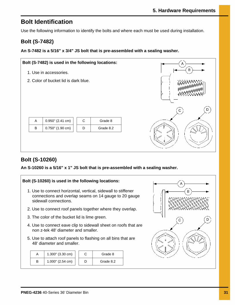
Bolt IdentificationUse the following information to identify the bolts and where each must be used during installation.
Bolt (S-7482)
An S-7482 is a 5/16" x 3/4" JS bolt that is pre-assembled with a sealing washer.
Bolt (S-10260)
An S-10260 is a 5/16" x 1" JS bolt that is pre-assembled with a sealing washer.
Bolt (S-7482) is used in the following locations:
1. Use in accessories.
2. Color of bucket lid is dark blue.
A 0.950" (2.41 cm) C Grade 8
B 0.750" (1.90 cm) D Grade 8.2
Bolt (S-10260) is used in the following locations:
1. Use to connect horizontal, vertical, sidewall to stiffener connections and overlap seams on 14 gauge to 20 gauge sidewall connections.
2. Use to connect roof panels together where they overlap.
3. The color of the bucket lid is lime green.
4. Use to connect eave clip to sidewall sheet on roofs that are non z-tek 48' diameter and smaller.
5. Use to attach roof panels to flashing on all bins that are 48' diameter and smaller.
A 1.300" (3.30 cm) C Grade 8
B 1.000" (2.54 cm) D Grade 8.2

5. Hardware Requirements
32 PNEG-4236 40-Series 36' Diameter Bin
Bolt (S-7483)
An S-7483 is a 5/16" x 1-1/4" JS bolt pre-assembled with a sealing washer.
Bolt (S-7485)
An S-7485 is a 3/8" x 1" JS hex bolt with flanged head and without a sealing washer.
Bolt (S-7483) is used in the following locations:
1. Use in base angle to sidewall connection.
2. Use for all stiffener to sidewall to stiffener connections with splice and for all 5 gauge stiffener to sidewall connections.
3. Use in accessories.
4. The color of the bucket lid is black.
5. Used in flashing to sidewall connections
A 1.437" (3.64 cm) C Grade 8
B 1.250" (3.17 cm) D Grade 8.2
Bolt (S-7485) is used in the following locations:
1. Use to splice the stiffeners together on the flanges. (A flange nut is used on the nut side of the connection.)
2. The color of bucket lid is light green.
A 1.350" (3.43 cm) C Grade 8
B 1.000" (2.54 cm) D Grade 8.2

5. Hardware Requirements
PNEG-4236 40-Series 36' Diameter Bin 33
Bolt (S-7487)
An S-7487 is a 3/8" x 1" JS bolt that is pre-assembled with a sealing washer.
Bolt (S-10261)
An S-10261 is a 7/16" x 3-1/4" JS bolt that is pre-assembled with a sealing washer.
Bolt (S-7487) is used in the following locations:
1. Use in all sidewall connections for 13 gauge through 10 gauge sidewall to sidewall sheets.
2. The color of bucket lid is light grey.
NOTE: Do not use to splice the stiffeners together on the flanges where they connect to each other or the splice plates.
A 1.350" (3.43 cm) C Grade 8
B 1.000" (2.54 cm) D Grade 8.2
Bolt (S-10261) is used in the following locations:
1. Use in wind ring splice and over pipe connections.
2. Lid color of bucket is natural (clear).
A 3.645" (9.26 cm) C Grade 8
B 3.250" (8.26 cm) D Grade 8.2

5. Hardware Requirements
34 PNEG-4236 40-Series 36' Diameter Bin
Color Chart for Bin Hardware Bucket Lids
For ease of identification, hardware is separated and identified by buckets with color coded lids. Use the following chart to help identify the correct hardware.
JS Part #
YDP Part #
ColorBucket Count
Lid Color Description
S-7482 NA Dark Blue 1500 5/16" x 3/4" Bolt pre-assembled with sealing washer
S-10260 NA Lime Green 1250 5/16" x 1" Bolt pre-assembled with sealing washer
S-7483 NA Black 1000 5/16" x 1-1/4" Bolt pre-assembled with sealing washer
NA S-396 Red 5000 5/16" Hex nut
S-10268 S-3611 Gold NA 5/16" Flange nut
S-7487 NA Grey 850 3/8" x 1" Bolt pre-assembled with sealing washer
S-7485 NA Light Green 1000 3/8" x 1" Flanged bolt without sealing washer
S-7488 NA Orange 650 3/8" x 1-1/2" Bolt pre-assembled with sealing washer
S-7489 S-456 Yellow 4000 3/8" Hex nut
S-9426 NA Dark Purple 2500 3/8" Hex flanged nut
S-10261 NA Natural (Clear) 200 7/16" x 3-1/4" Flange bolt pre-assembled with sealing washer
S-9281 NA Fire Orange 1500 7/16" Hex nut
PNEG-4236 40-Series 36' Diameter Bin 35
6. Gauge Sheet
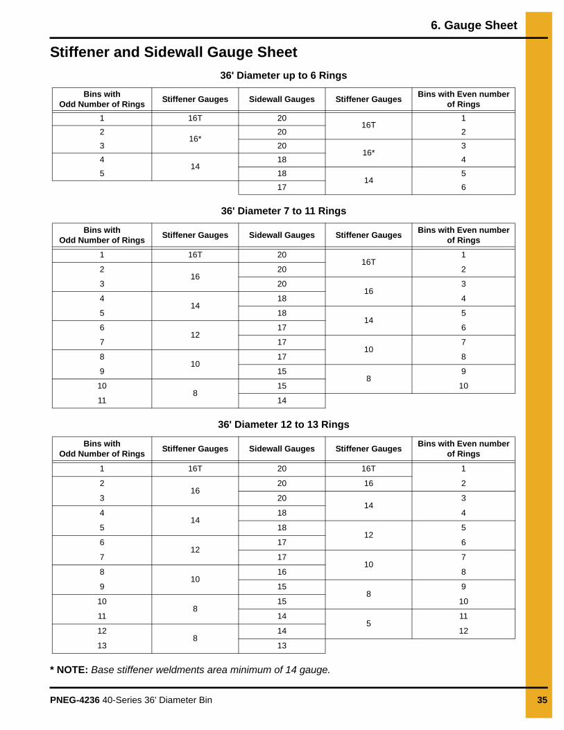
Stiffener and Sidewall Gauge Sheet
36' Diameter up to 6 Rings
36' Diameter 7 to 11 Rings
36' Diameter 12 to 13 Rings
* NOTE: Base stiffener weldments area minimum of 14 gauge.
Bins withOdd Number of Rings
Stiffener Gauges Sidewall Gauges Stiffener GaugesBins with Even number
of Rings
1 16T 2016T
1
216*
20 2
3 2016*
3
414
18 4
5 1814
5
17 6
Bins withOdd Number of Rings
Stiffener Gauges Sidewall Gauges Stiffener GaugesBins with Even number
of Rings
1 16T 2016T
1
216
20 2
3 2016
3
414
18 4
5 1814
5
612
17 6
7 1710
7
810
17 8
9 158
9
108
15 10
11 14
Bins withOdd Number of Rings
Stiffener Gauges Sidewall Gauges Stiffener GaugesBins with Even number
of Rings
1 16T 20 16T 1
216
20 16 2
3 2014
3
414
18 4
5 1812
5
612
17 6
7 1710
7
810
16 8
9 158
9
108
15 10
11 145
11
128
14 12
13 13

36 PNEG-4236 40-Series 36' Diameter Bin
7. Assembling Sidewall Sheets
Guidelines for Constructing Sidewall Sheets1. Before bolting the sidewall sheets together, check for the proper gauge of steel for the first ring.
Higher gauge numbers denote the thinner materials. (For example, 20 gauge material is thinner than 14 gauge.)
2. In erecting most grain bins, the thinnest material usually goes on top, therefore the first sidewall ring you assemble will be the top ring of the bin.
3. Check the various gauges of the bin with the color code chart and begin building accordingly.
4. Assemble the top ring first.
Color Codes for Sidewall Gauge IdentificationUse this chart to interpret the color code painted on the corners of the sidewall sheets.
Color Codes for Sidewall Gauges
Sidewall Gauge Color Code
20 Red
19 Black and Yellow
18 Orange
17 Light Blue and Pink
16 Blue
15 Red and Brown
14 Green
13 Blue and Yellow
12 Black
11 Pink
10 Light Blue
9 Blue and Orange
8 Yellow and Purple

7. Assembling Sidewall Sheets
PNEG-4236 40-Series 36' Diameter Bin 37
Orientation Detail for Top Sidewall Sheets
To avoid the misalignment of the holes, it is necessary to use the correct orientation of the sidewall sheet during installation. (See Figure 7A.)
NOTE: Always assemble the top sidewall sheets with the orientation shown.
Figure 7A 2 Post Top Sidewall Sheet Orientation (Viewed from Outside of the Bin)
Ref # Description
A Top of the Top Sidewall Sheet
B Bottom of the Top Sidewall Sheet

7. Assembling Sidewall Sheets
38 PNEG-4236 40-Series 36' Diameter Bin
Caulking and Bolting Detail for Standard Sidewall Sheets
To keep out moisture from overlapping the sheets, it is necessary to apply caulk to each sheet priorto installing. (See Figure 7B.)
NOTE: Always assemble the sidewall sheets with the overlap in the same direction.
Figure 7B Standard Sidewall Sheets as Viewed from the Outside of the Bin
Ref # Description
A Vertical Strip of Caulk
B 12" (30 cm) Horizontal Strip of Caulk

7. Assembling Sidewall Sheets
PNEG-4236 40-Series 36' Diameter Bin 39
Caulking and Bolting Detail for Standard Sidewall Sheets (Continued)
1. Apply a strip of caulk near the outside edge of the outer sheet and between the outer two (2) rows of bolts (A), then apply a strip of caulk 12" (30 cm) long along the horizontal seams (B), as shown in Figure 7C.
Figure 7C Caulking and Bolting Details (Viewed from Inside of the Bin)
2. Start assembling the sidewall sheets end to end (overlapping the same way throughout), until the ring is completed.
3. Install the correct size bin bolts with the bolt head and its neoprene washer to the outside and the nut on the inside of the bin.
NOTE: Do not tighten bolts until all the sheets are assembled and form a complete ring.
4. Tighten the bolts in sequence, starting from the center to the edge in both directions. This allows the sidewall sheets to draw-up evenly.
NOTE: Tighten from the nut side.
Ref # Description
A Strip of Caulk
B Bolt Tightening Sequence
C First Bolt
D Second Bolt
E Third Bolt
40 PNEG-4236 40-Series 36' Diameter Bin
8. Farm Stiffeners
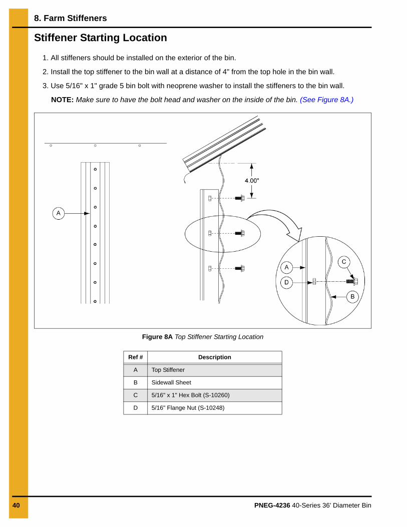
Stiffener Starting Location
1. All stiffeners should be installed on the exterior of the bin.
2. Install the top stiffener to the bin wall at a distance of 4" from the top hole in the bin wall.
3. Use 5/16" x 1" grade 5 bin bolt with neoprene washer to install the stiffeners to the bin wall.
NOTE: Make sure to have the bolt head and washer on the inside of the bin. (See Figure 8A.)
Figure 8A Top Stiffener Starting Location
Ref # Description
A Top Stiffener
B Sidewall Sheet
C 5/16" x 1" Hex Bolt (S-10260)
D 5/16" Flange Nut (S-10248)
8. Farm Stiffeners
PNEG-4236 40-Series 36' Diameter Bin 41
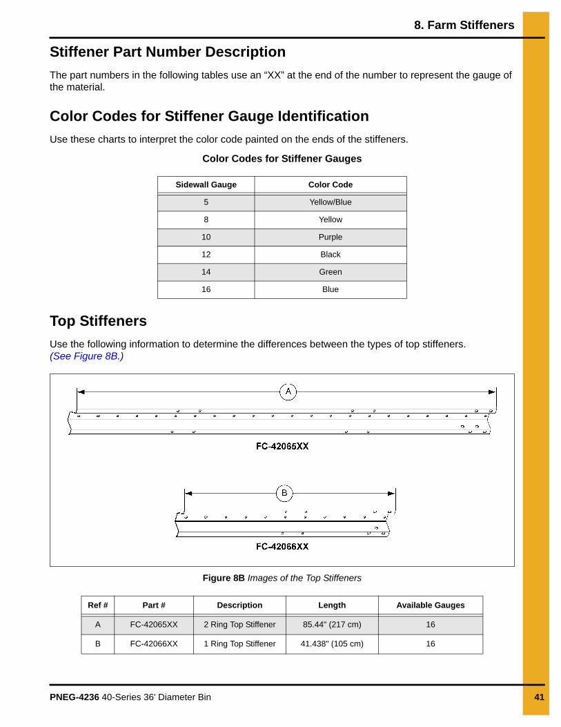
Stiffener Part Number Description
The part numbers in the following tables use an “XX” at the end of the number to represent the gauge of the material.
Color Codes for Stiffener Gauge Identification
Use these charts to interpret the color code painted on the ends of the stiffeners.
Color Codes for Stiffener Gauges
Top Stiffeners
Use the following information to determine the differences between the types of top stiffeners. (See Figure 8B.)
Figure 8B Images of the Top Stiffeners
Sidewall Gauge Color Code
5 Yellow/Blue
8 Yellow
10 Purple
12 Black
14 Green
16 Blue
Ref # Part # Description Length Available Gauges
A FC-42065XX 2 Ring Top Stiffener 85.44" (217 cm) 16
B FC-42066XX 1 Ring Top Stiffener 41.438" (105 cm) 16

8. Farm Stiffeners
42 PNEG-4236 40-Series 36' Diameter Bin
Standard Stiffeners
Use the following information to determine the differences between the types of standard 2 ring stiffeners. (See Figure 8C.)
Figure 8C Standard Stiffeners
Ref # Part # Description Length Available Gauges
A FC-42062XX 2 Ring Transition 94.594" (240 cm) 10
B FC-42057XX 2 Ring Offset Stiffener 94.594" (240 cm) 12 and 14
C FC-42075XX 2 Ring Offset Stiffener 93.563" (238 cm) 16
D FC-42063XX 2 Ring Stiffener 87.938" (223 cm) 8
E FC-42100XX 2 Ring Stiffener 87.938" (223 cm) 5
F FC-42059XX 1 Ring Offset Stiffener 50.594" (129 cm) 12 and 14
G FC-42074XX 1 Ring Offset Stiffener 49.563" (126 cm) 16

8. Farm Stiffeners
PNEG-4236 40-Series 36' Diameter Bin 43
Stiffeners SpliceUse the following information to determine the gauge of the splice needed to connect the stiffeners. (See Figure 8D.)
Figure 8D Stiffeners Splice
Base Boot
Use the following information to determine the differences between the base boots. (See Figure 8E.)
Figure 8E Images of the Base Boot
Ref # Part # Description Length Available Gauges
A FC-42076 Stiffeners Splice 10.688" (27 cm) 10
Ref # Part # Description Length Base Plate Dimensions
A FC-42107Base boot weldment for 14 gauge through 8 gauge base stiffeners.
6.188" (16 cm)4.5" x 7" x 1/4"
(11.5 cm x 17.8 cm x 0.6 cm)
B FC-42109Base boot weldment for 5 gauge base stiffeners.
6.188" (16 cm)5" x 7" x 1/2"
(12.7 cm x 17.8 cm x 1.3 cm)

8. Farm Stiffeners
44 PNEG-4236 40-Series 36' Diameter Bin
Base Stiffeners
Use the following information to determine the differences between the base stiffeners. (See Figure 8F.)
Figure 8F Images of the Base Stiffeners
Ref # Part # Description Length Available Gauges
A FC-42111XX Base Stiffener 87.938" (223 cm) 5
B FC-42063XX Base Stiffener 87.938" (223 cm) 8
C FC-42062XX Base Stiffener 94.594" (240 cm) 10
D FC-42057XX Base Stiffener 94.594" (240 cm) 12 and 14

8. Farm Stiffeners
PNEG-4236 40-Series 36' Diameter Bin 45
1 Ring Top Stiffener (16 Gauge) to a 1 Ring Stiffener (12-16 Gauge)
Refer the following information when connecting a 1 ring top stiffener (FC-42066XX) to a 1 ring stiffener. (See Figure 8G.)
Figure 8G
1 Ring Top Stiffener (16 Gauge) to a 2 Ring Stiffener (12-16 Gauge)
Refer the following information when connecting a 1 ring top stiffener (FC-42066XX) to a 2 ring stiffener. (See Figure 8H.)
Figure 8H
Ref # Part # Description
A FC-42066XX 1 Ring Top Stiffener
B 1 Ring Stiffener
C S-7485 3/8" x 1" Flange Bolt
D S-9426 3/8" Flange Nut
E Completed Assembly
NOTE: Only place bolts where holes in the stiffenersalign with holes in the sidewall sheet.
1 Ring Stiffener (B) Part Numbers
Stiffener Gauge Part #
14-12 FC-42059XX
16 FC-42074XX
Ref # Part # Description
A FC-42066XX 1 Ring Top Stiffener
B 2 Ring Stiffener
C S-7485 3/8" x 1" Flange Bolt
D S-9426 3/8" Flange Nut
E Completed Assembly
NOTE: Only place bolts where holes in the stiffenersalign with holes in the sidewall sheet.
2 Ring Stiffener (B) Part Numbers
Stiffener Gauge Part #
14-12 FC-42057XX
16 FC-42075XX

8. Farm Stiffeners
46 PNEG-4236 40-Series 36' Diameter Bin
2 Ring Top Stiffener (16 Gauge) to a 2 Ring Stiffener (12-16 Gauge)
Refer the following information when connecting a 2 ring top stiffener (FC-42065XX) to a 2 ring stiffener. (See Figure 8K.)
Figure 8I
2 Ring Stiffener (10 Gauge) to a 2 Ring Stiffener (8 Gauge)
Refer the following information when connecting a 2 ring stiffener to a 2 ring stiffener. (See Figure 8K.)
Figure 8J
Ref # Part # Description
A FC-42065XX 2 Ring Top Stiffener
B 2 Ring Stiffener
C S-7485 3/8" x 1" Flange Bolt
D S-9426 3/8" Flange Nut
E Completed Assembly
NOTE: Only place bolts where holes in the stiffenersalign with holes in the sidewall sheet.
2 Ring Stiffener (B) Part Numbers
Stiffener Gauge Part #
14-12 FC-42057XX
16 FC-42075XX
Ref # Part # Description
A FC-42062XX 2 Ring Top Stiffener (10 Gauge)
B FC-42063XX 2 Ring Stiffener (8 Gauge)
C S-7485 3/8" x 1" Flange Bolt
D S-9426 3/8" Flange Nut
E FC-42076 Splice Stiffener
F Completed Assembly
NOTE: Only place bolts where holes in the stiffenersalign with holes in the sidewall sheet.

8. Farm Stiffeners
PNEG-4236 40-Series 36' Diameter Bin 47
2 Ring Stiffener (12-16 Gauge) to a 2 Ring Stiffener (12-16 Gauge)
Refer the following information when connecting a 2 ring stiffener to a 2 ring stiffener. (See Figure 8K.)
Figure 8K
2 Ring Stiffener (5-8 Gauge) to a Base Stiffener (5-8 Gauge)
Refer the following information when connecting a 2 ring stiffener to a base stiffener (FC-42111). (See Figure 8K.)
Figure 8L
Ref # Part # Description
A FC-42057XX 2 Ring Stiffener (12-14 Gauge)
B FC-42075XX 2 Ring Stiffener (16 Gauge)
C S-7485 3/8" x 1" Flange Bolt
D S-9426 3/8" Flange Nut
E Completed Assembly
NOTE: Only place bolts where holes in the stiffenersalign with holes in the sidewall sheet.
Ref # Part # Description
A FC-42100XX 2 Ring Stiffener (5 Gauge)
B FC-42063XX 2 Ring Stiffener (8 Gauge)
C S-7485 3/8" x 1" Flange Bolt
D S-9426 3/8" Flange Nut
E FC-42076 Splice Stiffener
F Completed Assembly
NOTE: Only place bolts where holes in the stiffenersalign with holes in the sidewall sheet.

8. Farm Stiffeners
48 PNEG-4236 40-Series 36' Diameter Bin
2 Ring Stiffener (10-16 Gauge) to a Base Stiffener (10 Gauge)
Refer the following information when connecting a 2 ring stiffener to a base stiffener. (See Figure 8M.)
Figure 8M
2 Ring Stiffener (12-16 Gauge) to a Base Stiffener (12-14 Gauge)
Refer the following information when connecting a 2 ring stiffener to a base stiffener. (See Figure 8N.)
Figure 8N
Ref # Part # Description
A 2 Ring Stiffener
B FC-42062XX Base Stiffener
C S-7485 3/8" x 1" Flange Bolt
D S-9426 3/8" Flange Nut
E Completed Assembly
NOTE: Only place bolts where holes in the stiffenersalign with holes in the sidewall sheet.
2 Ring Stiffener (A) Part Numbers
Stiffener Gauge Part #
10 FC-42062XX
12-14 FC-42057XX
16 FC-42075XX
Ref # Part # Description
A 2 Ring Stiffener
B FC-42057XX Base Stiffener
C S-7485 3/8" x 1" Flange Bolt
D S-9426 3/8" Flange Nut
E Completed Assembly
NOTE: Only place bolts where holes in the stiffenersalign with holes in the sidewall sheet.
2 Ring Stiffener (A) Part Numbers
Stiffener Gauge Part #
12-14 FC-42057XX
16 FC-42075XX

8. Farm Stiffeners
PNEG-4236 40-Series 36' Diameter Bin 49
2 Ring Stiffener (5-8 Gauge) to a Base Stiffener (5 Gauge)
Refer the following information when connecting a 2 ring stiffener to a base stiffener (FC-42111). (See Figure 8O.)
Figure 8O
Transitional Stiffener (10 Gauge) to a Base Stiffener (8 Gauge)
Refer the following information when connecting a transitional stiffener to a base stiffener. (See Figure 8P.)
Figure 8P
Ref # Part # Description
A 2 Ring Stiffener
B FC-42111XX Base Stiffener
C S-7485 3/8" x 1" Flange Bolt
D S-9426 3/8" Flange Nut
E FC-42076 Splice Stiffener
F Completed Assembly
NOTE: Only place bolts where holes in the stiffenersalign with holes in the sidewall sheet.
2 Ring Stiffener (A) Part Numbers
Stiffener Gauge Part #
5 FC-42100XX
8 FC-42063XX
Ref # Part # Description
A FC-42062XX Transitional Stiffener (10 Gauge)
B FC-42063XX Base Stiffener (8 Gauge)
C S-7485 3/8" x 1" Flange Bolt
D S-9426 3/8" Flange Nut
E FC-42076 Splice stiffener
F Completed Assembly
NOTE: Only place bolts where holes in the stiffenersalign with holes in the sidewall sheet.

8. Farm Stiffeners
50 PNEG-4236 40-Series 36' Diameter Bin
Base Stiffener (8 Gauge) to a Base Boot (10 Gauge)
Refer the following information when connecting a base stiffener to a base boot (FC-42107). (See Figure 8Q.)
Figure 8Q
Base Stiffener (10-14 Gauge) to a Base Boot (10 Gauge)
Refer the following information when connecting a base stiffener to a base boot (FC-42107).(See Figure 8O.)
Figure 8R
Ref # Part # Description
A FC-42063XX Base Stiffener (8 Gauge)
B FC-42107 Base Boot
C S-7485 3/8" x 1" Flange Bolt
D S-9426 3/8" Flange Nut
E Completed Assembly
NOTE: Only place bolts where holes in the stiffenersalign with holes in the sidewall sheet.
Ref # Part # Description
A Base Stiffener
B FC-42107 Base Boot
C S-7485 3/8" x 1" Flange Bolt
D S-9426 3/8" Flange Nut
E Completed Assembly
NOTE: Only place bolts where holes in the stiffenersalign with holes in the sidewall sheet.
2 Ring Stiffener (A) Part Numbers
Stiffener Gauge Part #
10 FC-42062XX
12-14 FC-42057XX

8. Farm Stiffeners
PNEG-4236 40-Series 36' Diameter Bin 51
Base Stiffener (5 Gauge) to a Base Boot (10 Gauge)
Refer the following information when connecting a base stiffener to a base boot. (See Figure 8S.)
Figure 8S
Ref # Part # Description
A FC-42111 Base Stiffener (5 Gauge)
B FC-42109 Base Boot
C S-7485 3/8" x 1" Flange Bolt
D S-9426 3/8" Flange Nut
E Completed Assembly
NOTE: Only place bolts where holes in the stiffenersalign with holes in the sidewall sheet.

52 PNEG-4236 40-Series 36' Diameter Bin
9. Door Assembly
Standard Door Placement
Standard 2 ring door may be used for 12'-48' diameter bins for 13 rings and shorter heights. (See Figure 9A.)
Figure 9A Two Ring Door
Ref # Description
A First Ring (From Bottom of the Bin)
B Second Ring (From Bottom of the Bin)
C Door Assembly

9. Door Assembly
PNEG-4236 40-Series 36' Diameter Bin 53
2 Ring Door Installation
Before You Begin
Before starting to install, make sure the correct door has been received.
1. Remove the inner door panels (S, T and U) and outer door cover (A) from the door assembly.
2. Apply two (2) rows of rope caulk around all four door flanges: On vertical flanges, one row of caulk should be applied between the two (2) vertical rows of bolts and the other row of caulk should be applied between the door frame and the first row of vertical bolts. On the horizontal flanges, a row of caulk should be applied on each side of the row of bolts.
3. With the inner door panels (S, T and U) and outer door cover (A) removed, set door frame (Z) into sidewall opening. Insert a bolt at the four (4) corners of door frame and sidewall, but do not tighten until completing Step 4.
NOTE: Place the top of the door frame to the inside of the sidewall and the bottom of the door frame to the outside of the sidewall. Therefore, depending upon the location and overlap, caulk will be applied on either the inside or the outside of the door flanges.
4. Re-install the inner door panels (S, T and U) at original locations. Close latch bars (L) to lock panels in place. Make sure that panels are fully seated over all bearing pins (Q). Install the inner panel hinge (H, I and J) assemblies as per illustration instructions with hinges.
NOTE: Do not distort door frame with use of alignment or drift punches - if necessary, drill or ream holes to insert bolts in door frame. Now tighten frame bolts starting at center and working toward top and bottom on each side.
5. Keep inner panels (S, T and U) latched and loosen all bearing pin bolts. Re-tighten all bearing pin bolts. This makes loading on pins uniform for easier operation of panels.
6. If some latch bars are loose or require excessive force to lock, loosen hex socket cap screws and adjust in or out until latch bars operate smoothly. Check that the panels are fully seated over all bearing pins.
7. Re-install outer door cover (A). Adjust outer door hinges and latches as required.
8. Assemble door hold back (X and Y) as shown. Open door cover (A) until it approaches the bin wall. Hook the retaining bracket over lower latch mount and position the door hold back bracket against bin wall in a valley. Drill a 3/8" hole through the bin wall and bolt the door hold back bracket to the bin. If needed, install the door hold back extension to door hold back bracket.
9. Door Assembly
54 PNEG-4236 40-Series 36' Diameter Bin
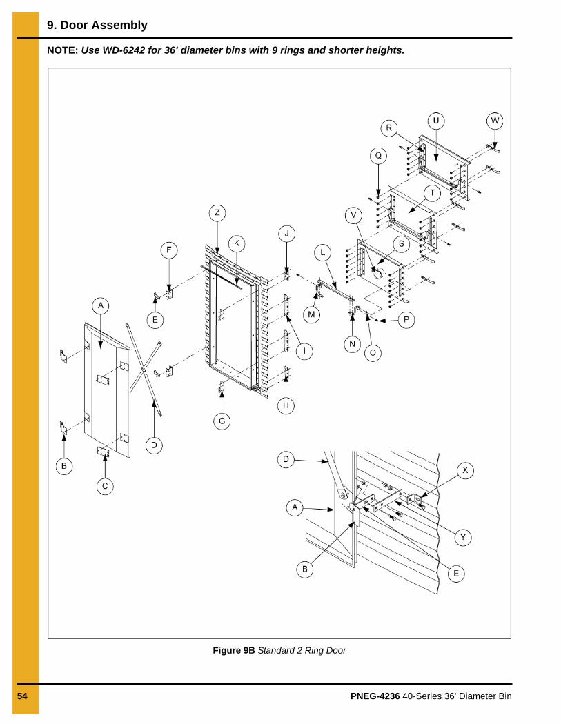
NOTE: Use WD-6242 for 36' diameter bins with 9 rings and shorter heights.
Figure 9B Standard 2 Ring Door

9. Door Assembly
PNEG-4236 40-Series 36' Diameter Bin 55
Ref # Part # Description Qty
A WD-039 Outer Door Cover 1
B WD-2854 Outer Cover Latch Bracket 2
C WD-225 Outer Cover Hinge Bracket 2
D WD-035 Door Cover Brace Section 4
E WD-033 Door Retainer 3
F WD-6124 Outer Cover Latch Mount Base 2
G WD-6066 Outer Cover Hinge Base 2
H WD-6055 Bottom Inner Door Hinge 1
I WD-6056 Middle Inner Door Hinge 1
J WD-6054 Top Inner Door Hinge 1
K S-4380 Rubber Trim Seal Strip
L WD-6039 Latch Bar 3
M WD-6037 Inner Panel Latch - Right Hand 3
N WD-6038 Inner Panel Latch - Left Hand 3
O WD-6040 Latch Bushing 6
P S-7160 1/2" x 1" Hex Socket Cap Screw 6
Q WD-6079 Long Bearing Pin 38
R WD-6125 Inner Panel Reinforcing Angle 6
S WD-6128 Bottom Inner Door Panel 1
T WD-6127 Middle Inner Door Panel 1
U WD-6126 Top Inner Door Panel 1
V WD-6028 Bottom Inner Door Port Hole Cover 1
U WD-6053 Inner Door Hinge Strap 6
W WD-1302 Door Hold Back Bracket 1
X WD-6110 Door Hold Back Extension 1
Y Door Frame Assembly

9. Door Assembly
56 PNEG-4236 40-Series 36' Diameter Bin
NOTE: Use WD-6244 for 36' diameter bins with 10-13 rings heights.
Figure 9C Heavy 2 Ring Door

9. Door Assembly
PNEG-4236 40-Series 36' Diameter Bin 57
Ref # Part # Description Qty
A WD-039 Outer Door Cover 1
B WD-2854 Outer Cover Latch Bracket 2
C WD-225 Outer Cover Hinge Bracket 2
D WD-035 Door Cover Brace Section 4
E WD-033 Door Retainer 3
F WD-6124 Outer Cover Latch Mount Base 2
G WD-6066 Outer Cover Hinge Base 2
H WD-6055 Bottom Inner Door Hinge 1
I WD-6056 Middle Inner Door Hinge 1
J WD-6054 Top Inner Door Hinge 1
K S-4380 Rubber Trim Seal Strip
L WD-6039 Latch Bar 3
M WD-6037 Inner Panel Latch - Right Hand 3
N WD-6038 Inner Panel Latch - Left Hand 3
O WD-6040 Latch Bushing 6
P S-7160 1/2" x 1" Hex Socket Cap Screw 6
Q WD-6079 Long Bearing Pin 38
R WD-6125 Inner Panel Reinforcing Angle 6
S WD-6140 Bottom Inner Door Panel 1
T WD-6141 Middle Inner Door Panel 1
U WD-6139 Top Inner Door Panel 1
V WD-6028 Bottom Inner Door Port Hole Cover 1
U WD-6053 Inner Door Hinge Strap 6
W WD-1302 Door Hold Back Bracket 1
X WD-6110 Door Hold Back Extension 1
Y WD-6147 Turnbuckle Latch Weldment 4
AA D32–003 Turnbuckle 5/8" x 9" 2
AB Special Heavy Door Frame Assembly

9. Door Assembly
58 PNEG-4236 40-Series 36' Diameter Bin
Options for 2 Ring Door - Bin Step
1. Attach the left and right sides (B and C) to the sides of the bin door step (D) using bolts (E) and nuts (G).
2. Center the assembled step under the bin door and use it as a template to field drill the holes (F) in the sidewall sheet on the ridges of the corrugation.
3. Install the bin step (A) to the sidewall sheet using bolts (E) and nuts (G). (See Figure 9D.)
Figure 9D Bin Step
Ref # Description Ref # Description
A Center Bin Step Under Door E 5/16" x 3/4" Hex Head Bolt
B Left Side (WD-041-1) FField drill holes in sidewall sheet on the ridge of corrugation.
C Right Side (WD-041-2) G 5/16" Nut
D Bin Door Step (WD-1984)

PNEG-4236 40-Series 36' Diameter Bin 59
10. Roof Assembly
Roof Assembly Instructions
IMPORTANT: Maximum weight to be supported and/or suspended from the roof is to be 6000 pounds for 36' bin (non-trussed) only.
1. After completing the first sidewall ring, begin with the center collar sections.
2. For convenience in opening and closing the center cover, the roof ladder and manhole sheet should be placed directly opposite the two (2) slide rod holes in the center collar.
3. Build a roof center support to hold the peak in place at the proper height.
4. Position the center support directly in the center of the bin.
5. Attach the eave angles or eave clips inside the bin wall.
The following dimensions are approximate distances used in bin roof construction. Adjusting the center support height will ease roof erection. (See Figure 10A.)
Figure 10A Center Support
NOTE: For 36' diameter bins, the height (A) is measured to the top of the intermediate center collar.
Ref # Description
A Bin Height
B Bin Diameter
C Center Support Pole
Bin DiameterUse with 1 Ring of 4.00'' Corrugated Sidewall
“A”
36' 13'-3''
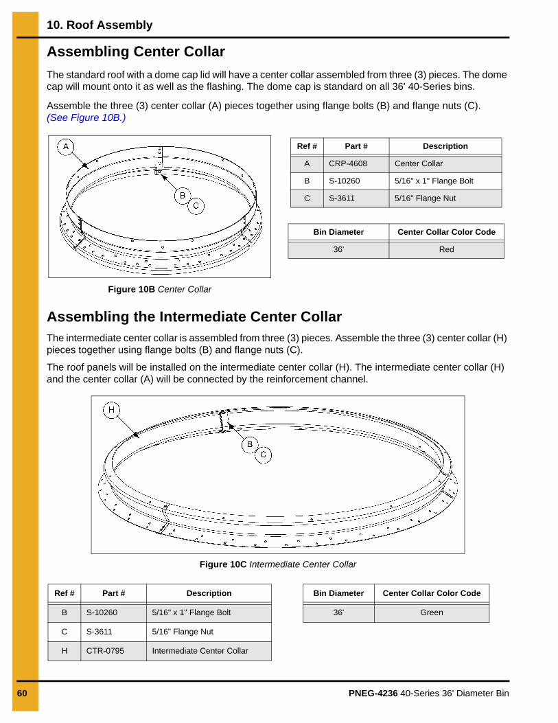
10. Roof Assembly
60 PNEG-4236 40-Series 36' Diameter Bin
Assembling Center Collar
The standard roof with a dome cap lid will have a center collar assembled from three (3) pieces. The dome cap will mount onto it as well as the flashing. The dome cap is standard on all 36' 40-Series bins.
Assemble the three (3) center collar (A) pieces together using flange bolts (B) and flange nuts (C). (See Figure 10B.)
Figure 10B Center Collar
Assembling the Intermediate Center CollarThe intermediate center collar is assembled from three (3) pieces. Assemble the three (3) center collar (H) pieces together using flange bolts (B) and flange nuts (C).
The roof panels will be installed on the intermediate center collar (H). The intermediate center collar (H) and the center collar (A) will be connected by the reinforcement channel.
Figure 10C Intermediate Center Collar
Ref # Part # Description
A CRP-4608 Center Collar
B S-10260 5/16" x 1" Flange Bolt
C S-3611 5/16" Flange Nut
Bin Diameter Center Collar Color Code
36' Red
Ref # Part # Description
B S-10260 5/16" x 1" Flange Bolt
C S-3611 5/16" Flange Nut
H CTR-0795 Intermediate Center Collar
Bin Diameter Center Collar Color Code
36' Green

10. Roof Assembly
PNEG-4236 40-Series 36' Diameter Bin 61
Roof Flashing
The roof flashing will seal the area between the center collar and the roof panels. The flashing pieces are assembled to the center collar after attaching the roof panels to the intermediate center collar.
1. After the assembly of the roof panels onto the intermediate center collar, the top center collar (A) and the flashing (C) should be positioned on top of the panels.
2. Position the flashing seam over the reinforcement angle seam (X) to ensure correct alignment.
NOTE: Improper positioning will result in holes and notches not aligning properly.The end of flashing must align with the splice in the lower center collar to align properly for the timing of tabs with the roof panels. Ensure to use flashing reinforcement angle at each flashing splice.
3. Apply caulking (B) to the center collar (A) where the flashing will be placed.
4. Apply caulking on each overlapping flashing.
5. Assemble the flashing (C) pieces together with the center collar (A) using flange bolts (D) and flange nuts (E).
Figure 10D Center Collar Flashing Assembly
Ref # Ref # Description
A CRP-4608 Center Collar
B S-10260 5/16" x 1" Flange Bolt
C S-3611 5/16" Flange Nut
D S-4458 Caulking
E CRP-4684 36' Roof Flashing
H CTR-0795 Intermediate Center Collar 36' Roof - Green (3)
X CRP-6188 Reinforcement Angle

10. Roof Assembly
62 PNEG-4236 40-Series 36' Diameter Bin
Roof Panel Instructions
1. For better results in erecting the roof, install one roof panel (B) in three (3) places.
2. After these three (3) panels are in place, the peak assembly should be centered.
3. Install intermediate panels making sure to lap them counterclockwise until all panels are in place.
NOTE: Do not tighten the bolts until the roof is completely assembled. Make sure to overlap the adjacent panels in counterclockwise direction as shown in Figure 10E.
NOTE: Do not install bolts onto the holes for roof ring locations until the roof rings are installed. See roof ring instructions on Page 68.
Figure 10E Roof Panels Installation Direction
4. Install the eave clips (I) and intermediate eave angles (L) on the top sidewall with the bolts (D) and nuts (E).
NOTE: The intermediate eave angles are installed between two (2) eave clips.
5. Fasten the roof panels (B) to intermediate eave angles (L) on the eave end and to the roof flashing (C) on the peak end.
6. When installing the roof panels (B), take into consideration placing the manway for ease of access to the sidewall and roof steps (K).
NOTE: Make sure to install the roof steps (K) when assembling roof panels. When assembling the roof steps (K), use 5/16" x 1-1/4" bolts with a flat top washer on top of the slot and an extra neoprene washer (L) between the roof and the roof step (K). This will ensure a more protective seal against moisture.
Ref # Part # Description Ref # Part # Description
A CRP-4608 Center Collar E S-3611 5/16" Flange Nut
B CTR-0386 Roof Panel F Upper Rib
C CRP-4684 Roof Flashing G Lower Rib
D S-10260 5/16" x 1" Flange Bolt
A
B
B
D
FG
C
E

10. Roof Assembly
PNEG-4236 40-Series 36' Diameter Bin 63
Roof Panel Instructions (Continued)
NOTE: For 36' diameter bins, an additional roof channel (P) must be installed under the ribs of the roof panel where the roof steps are to be installed. Make sure to start roof channel assembly from the second hole of bottom rib in the roof panel. (See Figure 10F.)
NOTE: For 36' diameter bins, the gap between the intermedite center collar (H) and the roof panels will be sealed with foam sealant (Q) around the center collar. (See Figure 10F.)
Figure 10F Roof Panel Assembly (36' Diameter Bin)
Ref # Description Ref # Description
B Roof Panel L Intermediate Eave Clip (CTR-1183)
D 5/16" x 1" Flange Bolt (S-10260) M Steel Backed Neoprene Washer (S-1463)
E 5/16" Flange Nut (S-3611) N Used with Standard Roofs
HIntermediate Center Collar 36' Roof - Green (3) (CTR-0795)
O Used with Top Dry Roofs
I Eave Clip (R-007-1) P Roof Channel
J Roof Channel Splice (CRP-5262) Q Foam Sealant - Z-Collar - 36' (S-10363)
K Roof Step
Roof Panel Information (B)
Bin Diameter Part # Roof Rib Holes Rib Length # of Panels
36' CTR-0386 12 218-1/8" 36
ED
N
H
Q
L
O
L
I
ED
P
J
B
P
L
B
D E
K
M
H
Bin outside
Bin inside
Bin outside
Bin inside

10. Roof Assembly
64 PNEG-4236 40-Series 36' Diameter Bin
Roof Panel Instructions (Continued)
7. To assemble slide rods (S) and peak cap (T), insert the straight end of the slide rod through the center collar (A) and thread one 5/16" nut all the way down on the rod. Place the rod through the cap and put a washer (X) and nut (W) on the outside. (See Figure 10G.)
NOTE: Do not tighten the nut.
8. Insert another rod through the cap, then place the washer (X) and nut (W) on the outside.
NOTE: Adjust and tighten nuts on straight end of rod.
Figure 10G Section through Center Collar
9. After tightening, it may be necessary to spread the rods slightly to make them parallel. Maintain a10" gap between the rods.
Ref # Part # Description
A CRP-4608 Center Collar
B CTR-0386 Roof Panel
C CRP-4684 Roof Flashing
R CRP-4689 Cap Hold-Down Bracket
S CRP-4606 Slide Rod
T CRP-4602 Peak Cap
U CRP-4654 Cap Hold-Down
V PR-331 Peak Cap Handle
W S-3611 5/16" Flange Nut
X Washer

10. Roof Assembly
PNEG-4236 40-Series 36' Diameter Bin 65
Installing the Manway CoverInstallation of a manway cover is necessary if a manway hole is present.
Round manway cover details for bins 60' and smaller.
1. Apply caulking to the underside of the moisture diverter (J) and install to the manway roof panel (N).
2. Install the hinge base (A) to the moisture diverter (J) and install three (3) hex bolts (C) and nuts (F).
3. Install the handle gasket (E) and the handle (D) to the cover (L) and secure with two (2) #10 long bolts (K) and lock nuts (M).
4. Install the latch (G) to the handle (D) using a hex bolt (C) and nut (F).
5. Install the hinge leaf (B) to the manway cover (L) and secure all four (4) bolts (C) and nuts (F). Install the manway assembly to the hinge base (A) and secure with two (2) bolts (K) and nuts (M).
NOTE: When securing the hinge leaf (B) to the hinge base (A), double nut each hex bolt (H).
6. Tighten the hardware.
7. Affix suffocation/flighting decals (not shown) to the underside of the manway cover.
NOTE: Suffocation/flighting decals replacement part numbers: English, DC-GBC-1A and Spanish, DC-GBC-1S.
8. Snap the manway seal strip (I) onto the lip of the manway hole.
9. Make the necessary adjustments to the handle (D) and latch (G), creating a tight seal. (See Figure 10H on Page 66.)
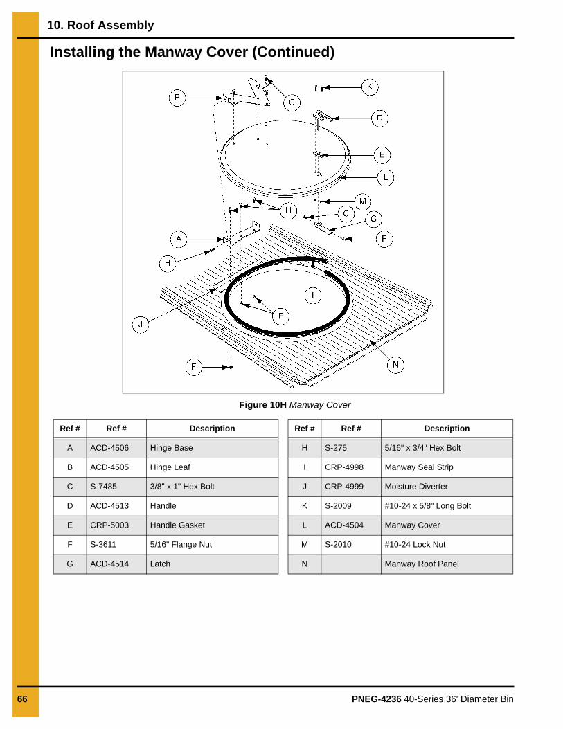
10. Roof Assembly
66 PNEG-4236 40-Series 36' Diameter Bin
Installing the Manway Cover (Continued)
Figure 10H Manway Cover
Ref # Ref # Description Ref # Ref # Description
A ACD-4506 Hinge Base H S-275 5/16" x 3/4" Hex Bolt
B ACD-4505 Hinge Leaf I CRP-4998 Manway Seal Strip
C S-7485 3/8" x 1" Hex Bolt J CRP-4999 Moisture Diverter
D ACD-4513 Handle K S-2009 #10-24 x 5/8" Long Bolt
E CRP-5003 Handle Gasket L ACD-4504 Manway Cover
F S-3611 5/16" Flange Nut M S-2010 #10-24 Lock Nut
G ACD-4514 Latch N Manway Roof Panel
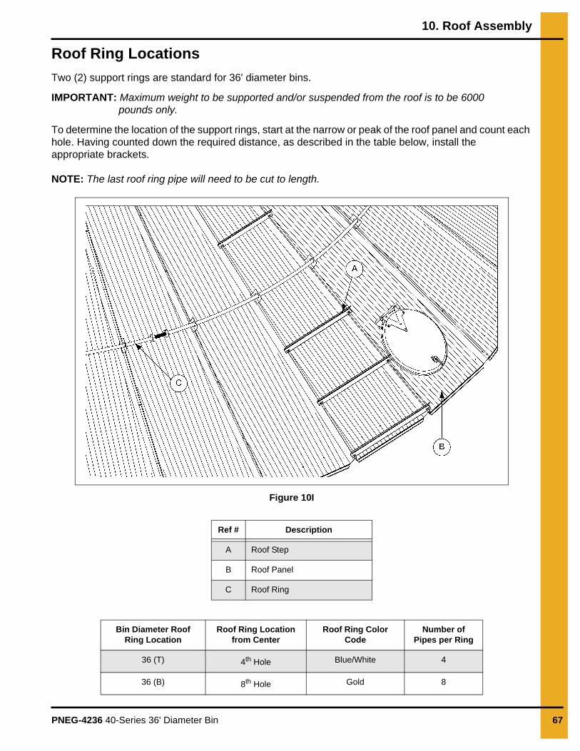
10. Roof Assembly
PNEG-4236 40-Series 36' Diameter Bin 67
Roof Ring Locations
Two (2) support rings are standard for 36' diameter bins.
IMPORTANT: Maximum weight to be supported and/or suspended from the roof is to be 6000 pounds only.
To determine the location of the support rings, start at the narrow or peak of the roof panel and count each hole. Having counted down the required distance, as described in the table below, install the appropriate brackets.
NOTE: The last roof ring pipe will need to be cut to length.
Figure 10I
Ref # Description
A Roof Step
B Roof Panel
C Roof Ring
Bin Diameter Roof Ring Location
Roof Ring Location from Center
Roof Ring Color Code
Number of Pipes per Ring
36 (T) 4th Hole Blue/White 4
36 (B) 8th Hole Gold 8

10. Roof Assembly
68 PNEG-4236 40-Series 36' Diameter Bin
Installing a Roof Ring
Quantity and part numbers of roof ring kits vary with the location placement and with the size of each bin. The following procedure will be similar for each kit.
1. Determine the quantity of roof ring clips (C) needed for the roof ring section (B) being installed.
NOTE: Each roof panel rib must have a roof ring clip installed.
2. Install a flange bolt (A) to the roof ring clip (C) and install a sealing washer (E) to the underside of the roof ring clip (C).
3. Slide each assembled roof ring clip (C) onto a roof ring section (B) and position each roof ring clip (C) over each roof panel rib.
4. Install a flange nut (D) to each roof ring clip (C). (See Figure 10J.)
NOTE: Do not tighten hardware until all roof ring sections have been installed.
Figure 10J Roof Ring Shown
Ref # Part # Description
A S-10260 5/16" x 1" Flange Bolt
B CRP-5363-XX Roof Ring Section
C R-997 Roof Ring Clip
D S-3611 5/16" Flange Nut
E S-3558 Sealing Washer
(-XX) Denotes the bin diameter.
A
BA
C
DC
B
E
D

10. Roof Assembly
PNEG-4236 40-Series 36' Diameter Bin 69
Installing a Roof Ring (Continued)
5. Locate a threaded stud (F) and install stud nuts (G) evenly and to the center of the threaded stud (F).
6. Install the threaded stud (F) with stud nuts (G) to the end of the roof ring section (B).
NOTE: Install the threaded stud (F) to the side where the next roof ring section will be installed.
7. Repeat this process, installing each new roof ring section end onto the preceding threaded stud just installed.
8. When all roof ring sections are installed, tighten each roof ring clip (B).
9. Adjust each stud nut (G) outward, expanding each roof ring section. Continue this procedure evenly until the roof ring raises the roof, showing a slight crown.
NOTE: Expansion bolts should be fully contracted when assembling support rings. When you have completely assembled both rings, (but prior to expanding the bolts) tighten all roof bolts including eave clip bolts. Now extend expansion bolts by running the nut out on the threads. This procedure should be continued evenly around the roof until the ring raises the roof to show a slight crown.
NOTE: Roof ring expansion bolts may become dislodged from the roof ring during the life of the bin due to the influence of wind or other factors. If one expansion bolt is dislodged, the entire ring will become ineffective. After expansion to the jam nuts final position, the nuts on the expansion bolt should be secured to prevent this. This may be done by staking the expansion bolt threads at the jam nut location, use of suitable thread locking compounds or other effective methods. (See Figure 10K.)
In addition, drilling holes through the support pipe and expansion bolt and connecting together with a 1/4" diameter bolt is an effective way to prevent the bolt from dislodging during certain wind and pressure conditions.
Figure 10K Exploded View of Threaded Stud
Ref # Part # Description Ref # Part # Description
B CRP-5363-XX Roof Ring Section G S-8926 Stud Nut
F S-8765 Threaded Stud (-XX) Denotes the bin diameter.
FB B
B
GB
F
G
G

10. Roof Assembly
70 PNEG-4236 40-Series 36' Diameter Bin
Assembling the Auto Roof Vent
The following instructions are for assembling the auto-vent. First, check the packing list to ensure all components have been shipped. The unit is easiest assembled in the upside-down position as shown in the instructions.
1. Take all parts out of the shipping box and ensure all parts are present.
2. Turn the roof vent housing assembly (D) upside down.
3. Install a bolt (B) through the hole on the side of roof vent housing (D). Install a flange nut (E) to thebolt (B) and tighten.
4. With the curvature facing upward, install the flap assembly (F) into the roof vent housing (D) and onto the end of the bolt (B).
5. Insert another bolt (B) through the other side of the roof vent housing (D) and install a flange nut (E) to the bolt (B), between the tab of the flap assembly (F) and the side of roof vent housing (D).
6. Apply a strip of caulking around the three (3) housing sides of the roof vent assembly (D) where it meets the hold-down angle (A).
7. Place the hold-down angle (A) onto the assembled roof vent assembly (D), with the wide end or long end of the hold-down angle (A) facing the vent discharge and the short end facing the rear of the vent.
8. When the hold-down angle (A) is aligned, install #10 self-drilling screws through the roof housing and into the hold-down angle (A). (See Figure 10L.)
Figure 10L Auto Roof Vent Assembly
Ref # Part # Description Ref # Part # Description
A MIS-4404 Hold-Down Angle D MIS-6778 Roof Vent Housing Assembly
B S-7483 5/16" x 1-1/4" Flange Bolt E S-3611 5/16" Flange Nut
C S-280 #10 Self-Drilling Screws F MIS-6777 Flap Assembly
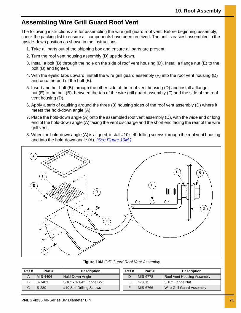
10. Roof Assembly
PNEG-4236 40-Series 36' Diameter Bin 71
Assembling Wire Grill Guard Roof VentThe following instructions are for assembling the wire grill guard roof vent. Before beginning assembly, check the packing list to ensure all components have been received. The unit is easiest assembled in the upside-down position as shown in the instructions.
1. Take all parts out of the shipping box and ensure all parts are present.
2. Turn the roof vent housing assembly (D) upside down.
3. Install a bolt (B) through the hole on the side of roof vent housing (D). Install a flange nut (E) to the bolt (B) and tighten.
4. With the eyelid tabs upward, install the wire grill guard assembly (F) into the roof vent housing (D) and onto the end of the bolt (B).
5. Insert another bolt (B) through the other side of the roof vent housing (D) and install a flange nut (E) to the bolt (B), between the tab of the wire grill guard assembly (F) and the side of the roof vent housing (D).
6. Apply a strip of caulking around the three (3) housing sides of the roof vent assembly (D) where it meets the hold-down angle (A).
7. Place the hold-down angle (A) onto the assembled roof vent assembly (D), with the wide end or long end of the hold-down angle (A) facing the vent discharge and the short end facing the rear of the wire grill vent.
8. When the hold-down angle (A) is aligned, install #10 self-drilling screws through the roof vent housing and into the hold-down angle (A). (See Figure 10M.)
Figure 10M Grill Guard Roof Vent Assembly
Ref # Part # Description Ref # Part # Description
A MIS-4404 Hold-Down Angle D MIS-6778 Roof Vent Housing Assembly
B S-7483 5/16" x 1-1/4" Flange Bolt E S-3611 5/16" Flange Nut
C S-280 #10 Self-Drilling Screws F MIS-6766 Wire Grill Guard Assembly
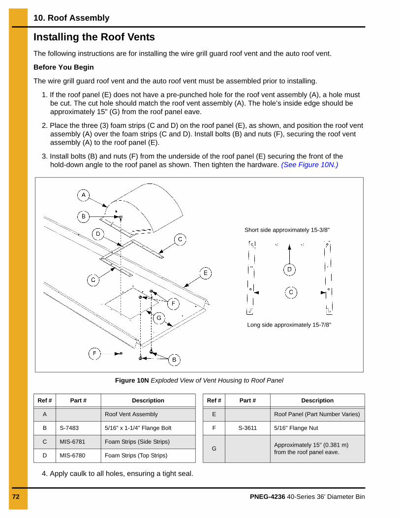
10. Roof Assembly
72 PNEG-4236 40-Series 36' Diameter Bin
Installing the Roof Vents
The following instructions are for installing the wire grill guard roof vent and the auto roof vent.
Before You Begin
The wire grill guard roof vent and the auto roof vent must be assembled prior to installing.
1. If the roof panel (E) does not have a pre-punched hole for the roof vent assembly (A), a hole must be cut. The cut hole should match the roof vent assembly (A). The hole’s inside edge should be approximately 15" (G) from the roof panel eave.
2. Place the three (3) foam strips (C and D) on the roof panel (E), as shown, and position the roof vent assembly (A) over the foam strips (C and D). Install bolts (B) and nuts (F), securing the roof vent assembly (A) to the roof panel (E).
3. Install bolts (B) and nuts (F) from the underside of the roof panel (E) securing the front of the hold-down angle to the roof panel as shown. Then tighten the hardware. (See Figure 10N.)
Figure 10N Exploded View of Vent Housing to Roof Panel
4. Apply caulk to all holes, ensuring a tight seal.
Ref # Part # Description Ref # Part # Description
A Roof Vent Assembly E Roof Panel (Part Number Varies)
B S-7483 5/16" x 1-1/4" Flange Bolt F S-3611 5/16" Flange Nut
C MIS-6781 Foam Strips (Side Strips)G
Approximately 15" (0.381 m) from the roof panel eave.
D MIS-6780 Foam Strips (Top Strips)
Long side approximately 15-7/8"
Short side approximately 15-3/8"

PNEG-4236 40-Series 36' Diameter Bin 73
11. Accessories
Ladder Section Assembly
The inside ladder package consists of the ladder, starter brackets, standoff brackets, reinforcement straps and ending bracket. The ladder should to be assembled before installing it to the bin structure.
What You Should Know
When assembling ladder sections, ensure all slip resistant ladder rungs are oriented in the same direction.
NOTE: A portion of the last ladder section may need to be cut to fit the proper length to the ground or to the intermediate platform.
1. Place two (2) ladder sections (A) together as shown.
2. Install a splice plate (C) to each outside channel, connecting the ladder sections (A).
3. Install flange bolts (D) to each inside channel as shown, connecting the ladder sections (A).
4. Install flange nuts (B) to each outside channel as shown, securing the ladder sections (A). Tighten to the recommended torque specifications. See bolt torque specifications on Page 30.).
Figure 11A Assembling the Inside Ladder Sections
Ref # Part # Description
A Ladder Section
B S-3611 5/16" Flange Nut
C LDR-4317 Splice Plate
D S-7482 5/16" x 3/4" Flange Bolt

11. Accessories
74 PNEG-4236 40-Series 36' Diameter Bin
Inside Ladder PlacementThe inside ladder provides manway access from inside the bin.
What You Should Know
Begin by temporarily positioning the ladder (B) directly under the manway roof panel (A) for the correct placement location. Mark or scribe this location where each side of the ladder’s vertical channels meet the sidewall.
Figure 11B Positioning the Ladder
1. Install the right hand starter bracket (C) to the top hole in the first sidewall ring, located closest to the eave. Install a flange bolt (D) and secure with a flange nut (G).
2. Measure approximately 18-3/4" (E) to the left of the R.H. starter bracket (C) and install the L.H. starter bracket (K) to the top hole in the first sidewall ring, located closest to the eave. Install a flange bolt (D) and secure with a flange nut (G).
3. Temporarily position the ladder back into place, ensuring that the mating surface of each starter brackets (C and K) are aligned with the inside mating surface of each vertical channel of the ladder (B).
4. Field drill a second 3/8" hole (F) using the bottom hole in the starter brackets (C and K) as guides. Install a flange bolt (D) and secure with a flange nut (G). Tighten hardware to the recommended torque specifications. See bolt torque specifications on Page 30.)
5. Working down from the starter brackets (C and K) and in alignment, install a ladder standoff bracket (H) at every horizontal seam or 32" from the previous installed bracket. Install a flange bolt (D) and a flange nut (G), securing each ladder standoff bracket (H) to the sidewall.
NOTE: Installing a plumb line to the starter bracket will help keep each bracket aligned evenly.
6. Install a ladder reinforcing strap (I) to the ladder standoff brackets (H) and install two (2) hex bolts (J) and nuts (G).
NOTE: For optimal reinforcement, install the ladder reinforcing straps (I) in a diagonal fashion as shown.
Ref # Description
A Manway Access
B Ladder Assembly

11. Accessories
PNEG-4236 40-Series 36' Diameter Bin 75
7. Tighten hardware to the recommended torque specifications. See bolt torque specifications on Page 30.)
8. Install the ladder (B) to the starter brackets (C and K) and install hex bolts (M) and nuts (N), but do not tighten at this time.
9. Install a carriage bolt (Q) to a standoff wedge (O) and insert into the outside channel of the ladder assembly (B).
10. Connect the standoff wedge (O) to the standoff bracket (H) and install a flange nut (P), but do not tighten allowing, for adjustment.
Figure 11C Installing Ladder Brackets
Repeat this process for the remaining standoff brackets.
11. Field drill a 3/8" hole (L) and install hex bolts (M) and nuts (N), securing the ladder to the starter brackets (C and K).
12. Tighten all hardware to the recommended torque specifications. See bolt torque specifications on Page 30.).
Ref # Description Ref # Description
B Ladder Assembly J 5/16" Hex Bolt (S-7482)
C Starter Bracket (R.H.) LDR-4347) K Starter Bracket (L.H.) LDR-4346)
D See Sidewall Hardware Chart L 3/8" Field Drilled Hole Location
E Approximately 18-3/4" (47.62 mm) M 5/16" x 3/4" Flange Bolt (S-7482)
F 3/8" Field Drilled Hole Location N 5/16" Flange Nut (S-3611)
G 5/16" Hex Nut (S-396) O Standoff Wedge (LDR-4198)
H Standoff Bracket (LDR-4314) P 5/16" Flange Nut (S-3611)
I Ladder Reinforcing Strap (LDR-5132) Q 5/16" x 1" Carriage Bolt (S-3550)
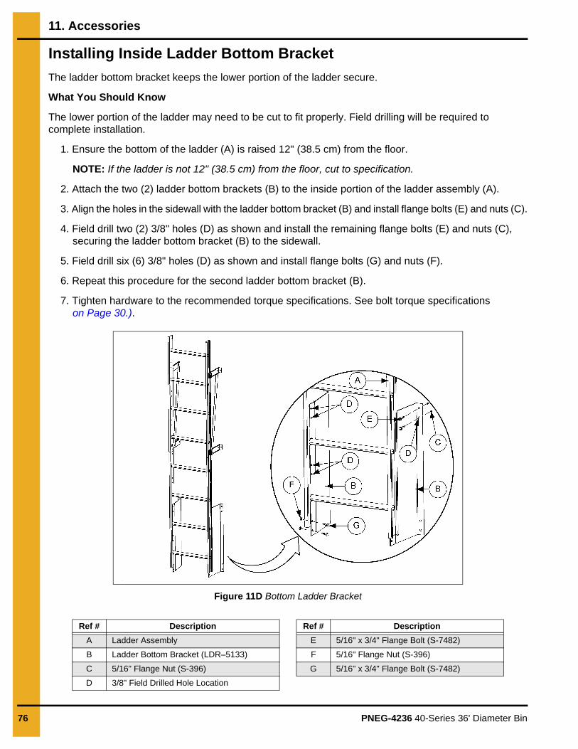
11. Accessories
76 PNEG-4236 40-Series 36' Diameter Bin
Installing Inside Ladder Bottom Bracket
The ladder bottom bracket keeps the lower portion of the ladder secure.
What You Should Know
The lower portion of the ladder may need to be cut to fit properly. Field drilling will be required to complete installation.
1. Ensure the bottom of the ladder (A) is raised 12" (38.5 cm) from the floor.
NOTE: If the ladder is not 12" (38.5 cm) from the floor, cut to specification.
2. Attach the two (2) ladder bottom brackets (B) to the inside portion of the ladder assembly (A).
3. Align the holes in the sidewall with the ladder bottom bracket (B) and install flange bolts (E) and nuts (C).
4. Field drill two (2) 3/8" holes (D) as shown and install the remaining flange bolts (E) and nuts (C), securing the ladder bottom bracket (B) to the sidewall.
5. Field drill six (6) 3/8" holes (D) as shown and install flange bolts (G) and nuts (F).
6. Repeat this procedure for the second ladder bottom bracket (B).
7. Tighten hardware to the recommended torque specifications. See bolt torque specificationson Page 30.).
Figure 11D Bottom Ladder Bracket
Ref # Description Ref # Description
A Ladder Assembly E 5/16" x 3/4" Flange Bolt (S-7482)
B Ladder Bottom Bracket (LDR–5133) F 5/16" Flange Nut (S-396)
C 5/16" Flange Nut (S-396) G 5/16" x 3/4" Flange Bolt (S-7482)
D 3/8" Field Drilled Hole Location

11. Accessories
PNEG-4236 40-Series 36' Diameter Bin 77
Guidelines for Installing a Sidedraw SystemA sidedraw system will allow content unloading using gravity and is done from the side of the bin.
General Guidelines to follow before Installing a Sidedraw System:
NOTE: If a sidedraw system is installed, the standard 5/8" anchor bolts must be replaced with 3/4" anchor bolts.
• Side discharge is only permitted in stiffened bins when a GSI manufactured sidedraw flume system has been installed. No corrugated steel bin must be unloaded through the side wall without installation of such a system and permission of the manufacturer.
• A sidedraw should not be the only discharge system available. A standard center discharge and conveyor must be installed.
• Installation of multiple systems may require additional wind rings and must be placed a minimum of 90° apart. Installation of multiple systems requires approval of GSI.
• Sidedraw systems are intended for use with dry, flowable grain. Sidedraws are not to be used for poorly flowing products. This is not unique to GSI bins and flume systems, but is a general rule for such systems.
• In multiple system installations, only one sidedraw may be used at any one time.
• Filling must not be occurring at the same time as grain is being withdrawn through the sidedraw flume system.
• Prolonged storage of grain in the sloped condition produced by sidedraw discharge may accelerate differential settlement and result in deformations of the bin. After using the sidedraw system, the sloped grain must be returned to a near level condition by use of the center discharge. Leveling of the grain should also allow more even consolidation of foundation and fill soils and produce more even settlement of the bin.
• If past experience or geotechnical investigations indicate significant foundation level soil variations or a site propensity toward differential settlement, sidedraw usage may be prohibited or severely restricted. In this situation the use of a flume system should be reviewed with geotechnical consultants or the foundation engineer.
• Before installing, determine if bin design is a 2 post stiffener (A).
• Do not install a discharge chute on a vertical seam.
• A discharge chute should be installed at the standard height (C).

11. Accessories
78 PNEG-4236 40-Series 36' Diameter Bin
Figure 11E Sidedraw Installation
Ref # Descriptions
A Stiffeners
B Sidewall Sheet
C 17' - 2"
D 44" Typical
E Starting Dimension For First Chute
F Required Spacing Between Chute Bolt Holes (8")
G 15"
H 12-3/4"
I 14"
J 5th Horizontal Seam From Base
K 1st Bolt Hole in Top Chute

11. Accessories
PNEG-4236 40-Series 36' Diameter Bin 79
Locating the Chutes
Use the following procedures to locate the starting position of the first chutes.
1. Starting from the first row of holes in the top sheet, measure down the “starting distance” for the bin. See Sidedraw Chute Chart on Page 79. (See Figure 11E on Page 78 and See Figure 11F.)
2. Keep adding the required number of chutes, making sure to leave 8" between the chute bolt holes. (See Figure 11E on Page 78.)
Figure 11F Locating the Chutes
Ref # Descriptions
A First Hole in Top Sheet
B Starting Dimension for First Chute
C Distance between chute bolt holes.
Sidedraw Chute Installation
Number of Rings Starting Dimension Number of Chutes Horizontal Location for First Chute
13 54" 10 Middle of Sheet
12 42" 9 Middle of Sheet
11 62" 7 Middle of Sheet
10 50" 6 Middle of Sheet
9 38" 5 Middle of Sheet
8 58" 4 Middle of Sheet
7 48" 3 Middle of Sheet
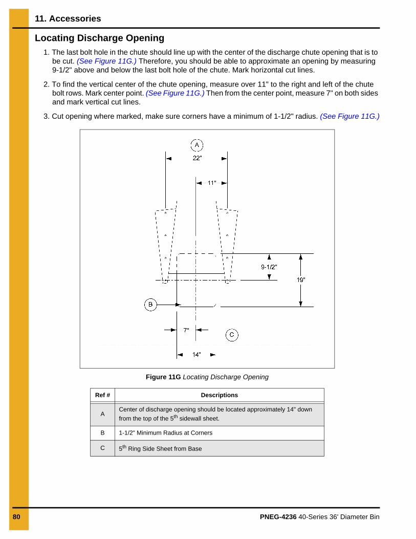
11. Accessories
80 PNEG-4236 40-Series 36' Diameter Bin
Locating Discharge Opening
1. The last bolt hole in the chute should line up with the center of the discharge chute opening that is to be cut. (See Figure 11G.) Therefore, you should be able to approximate an opening by measuring 9-1/2" above and below the last bolt hole of the chute. Mark horizontal cut lines.
2. To find the vertical center of the chute opening, measure over 11" to the right and left of the chute bolt rows. Mark center point. (See Figure 11G.) Then from the center point, measure 7" on both sides and mark vertical cut lines.
3. Cut opening where marked, make sure corners have a minimum of 1-1/2" radius. (See Figure 11G.)
Figure 11G Locating Discharge Opening
Ref # Descriptions
ACenter of discharge opening should be located approximately 14" down
from the top of the 5th sidewall sheet.
B 1-1/2" Minimum Radius at Corners
C 5th Ring Side Sheet from Base

11. Accessories
PNEG-4236 40-Series 36' Diameter Bin 81
Sidewall Overlap
1. For proper watershed, make sure that the upper side sheet overlaps on top of the sidedraw weldment. (See Figure 11H.)
Figure 11H Sidewall Overlap
Ref # Descriptions
A Chute
B 6th Ring from Base
C 5th Ring Side Sheet *Must be Field Cut*
D Top of 5th Side Sheet
E Sidedraw Plate Weldment
F 4th Horizontal Seam from Base
G 4th Ring from Base

11. Accessories
82 PNEG-4236 40-Series 36' Diameter Bin
Caulking
1. To seal the sidedraw weldment to the sidewall sheets, use two (2) beads of caulking, one bead of caulk on each side of the outside row of vertical bolts.
2. Use discharge tube weldment as a template to field drill the bolt holes through sidewall sheet.
3. Use 3/8" bolts and nuts provided to bolt sheets together.
Figure 11I Caulking Figure 11J Caulking
Ref # Descriptions
E Sidedraw Plate Weldment
H Sidewall Sheet
I Caulking
Ref # Descriptions
J Field Cut Hole
K Use as template to field drill holes.

11. Accessories
PNEG-4236 40-Series 36' Diameter Bin 83
Wind Ring Requirements
Wind rings give additional strength against high winds and uneven loads. The quantities and placement of wind rings will depend on the size of bin being constructed.
For 36' diameter bins with 13 rings and shorter heights, standard sidedraw wind ring used is placed in the second ring. Refer the table below for the wind ring requirements.
Figure 11K Dimensions for OSHA Compliant Ladder Rung Placement
Installing Wind Rings
What You Should Know
Before installing, determine the bin size, sidewall gauge thickness and height. Use the hardware chart on Page 29.) to match the correct bolt length with the correct sidewall gauge thickness when installing the wind ring brackets to the stiffeners (Refer to hardware requirements on Page 29.) To determine the location of the wind rings or if additional wind rings will be needed for sidedraw systems, see wind ring requirement on Page 83.
1. Place a wind ring section (B) into the channel of the stiffener (A) and install two (2) C-clamps (F), securing with flange bolts (E) and flange nuts (G). Do not tighten until all wind ring sections are installed.
2. Repeat this procedure, inserting each wind ring section (B), over the previously installed wind ring section, securing the wind ring sections together with flange bolts (E) and hex nuts (G).
Wind Ring Requirements
Rings 36'
10 1
11 1
12 1
13 1
NOTE: Ensure the wind rings are installed in relation to the ladder rungs as shown to meetO.S.H.A. specifications.
1-1/2" Minimum
4-1/2" Minimum

11. Accessories
84 PNEG-4236 40-Series 36' Diameter Bin
3. Before installing the last wind ring section (B), slide a wind ring coupling collar (H) over the wind ring section (B).
4. Install the last wind ring section (B) and cut the wind ring section to the proper length.
NOTE: The cut needs to be made in a location that allows minimal space between the pipes.
5. Slide the wind ring coupling collar (H), aligning the three pre-drilled holes, and install flange bolts (C) and hex nuts (D). Field drill the remaining three (3) holes (I) using the wind ring coupling collar (H) as a guide or template.
6. Install the remaining flange bolts (E) and hex nuts (D), and tighten all hardware to the recommended torque specifications. See bolt torque specifications on Page 29.
Figure 11L Exploded View of Wind Ring Installed at Upper Portion of Stiffener
NOTE: (-XX) denotes the bin diameter.
Ref # Part # Description
A Varies Stiffener
BCTS-1004-XX (or) CTS-1002-XX
Wind Ring Section
C S-10261 Flange Bolt 7/16"-14 x 3-1/4" JS Grade 8.2 with Sealing Washer
D S-9281 Hex Nut 7/16"-14 JS Grade 5
E S-7485 Flange Bolt 3/8"-16 x 1" JS Grade 8 or Grade 8.2
F SS-7248 C-Clamp
G S-9426 Flange Nut 3/8"-16 JS
H CTS-1006 Wind Ring Coupling Collar
I Field Drilled Hole Location

11. Accessories
PNEG-4236 40-Series 36' Diameter Bin 85
Temperature Cable Support Package Instructions for Eave Heights of 40'-5" (12.32 m) or Less (Optional)Use these instructions for the temperature cable support package installation of 36' (10.97 m) diameter bins.
1. For 36' (10.97 m) diameter bins, the temperature cable support package shall span one roof panel.
2. The rafter support system (included in each package) will be necessary for the temperature cable installation in 36' (10.97 m) diameter bins that have an eave height less than 40'-5" (12.32 m).
3. One package should be provided for each cable in the tank with the exception of the center cable.
4. All packages include hanging angle and a cable support channel.
5. Each set of roof channel should carry only one temperature cable.
6. The two (2) roof channel (F) sections are spliced together with roof channel splice (CRP-5262).
7. Field drill holes and install the reinforcement angle (E) to the outside of the roof channels (F).
NOTE: Locate the reinforcement angle along the roof channel (F) in location specified by temperature cable manufacturer. Place the reinforcement angle and drill eight (8) holes in the web and four (4) holes in the flange evenly distributed over the length of the roof channel (F).
8. Once the rafters are in place, field drill the holes to bolt the temperature support angles (A and B) into the roof channel (F) and attach with 3/8" bolts.
9. Install the support channel (D) onto the support angles (A and B) with 3/8" bolts.
10. Attach the cable attachment bracket (C) in the center of the support channel (D) to hang the cable.
Figure 11M
Ref # Part # Description Ref # Description
A CRP-5787 L.H. Temperature Cable Support Angle D Support Channel
B CRP-5786 R.H. Temperature Cable Support Angle E Reinforcement Angle (CRP-5422)
C Cable Attachment Bracket F Roof Channel (CRP-4793)

11. Accessories
86 PNEG-4236 40-Series 36' Diameter Bin
11. No more than one cable should be supported from a pair of roof rafters.
12. If it is desired to support the cable from the flange of the support channel, it will be necessary to reinforce the flange with a 12" section of 3" x 3" x 3/16" angle.
13. Temperature cables are to be installed at the radii specified by the temperature cable manufacturer.
14. This package will allow a maximum radius of 13.31' (4.06 m) for a 36' diameter bin.
NOTE: This radius represents the maximum radius that the cross members will span. These are not recommended installation locations.
15. For a greater radius, a cross member adequate to support the cable must be provided (by others). However the rafter support system must be used.
Temperature Cable Support Package Instructions (for Eave Heights Greater than 40'-5" (12.32 m)) (Optional)
1. For 36' (10.97 m) diameter two (2) post bins, the temperature cable support package shall span three (3) roof panels.
2. A rafter support system (included in each package) will be necessary for temperature cable installation in 36' bins (10.97 m).
3. One package should be provided for each cable in the tank with the exception of the center cable.
4. All packages include hanging angle and a cable support channel.
5. Each set of rafters should carry only one temperature cable.
6. Each kit will contain two (2) rafter sections, which when spliced will reach from the center collar to the bin wall. The lower rafter (C) will be bolted into the stiffener bracket (A).
Figure 11N Lower Rafter Assembly
Ref # Description
A Stiffener Bracket (CRP-4758)
B 3/8" Bolt (S-7487) and 3/8" Nut (S-456)
C Lower Rafter (CRP-7241)

11. Accessories
PNEG-4236 40-Series 36' Diameter Bin 87
7. The upper rafter (D) will be bolted into the intermediate center collar (G) using the rafter attachment brackets (E).
Figure 11O Upper Rafter Assembly (For 36' Diameter Bins)
8. The rafter packages will utilize the standard splice plate (L) but will have no purlins.
9. The upper rafter (D) and the lower rafter are connected with the standard splice plate (L) using 3/8" bolts.
10. Once the rafters are in place, field drill the holes to bolt the support angles (H and I) and into the roof rafter and attach with 3/8" bolts.
11. Install the support channel (K) onto the support angles (H and I) using 3/8" bolts.
12. Attach the cable attachment bracket (J) in the center of the support channel (K) to hang the cable.
Ref # Description
D Upper Rafter (CRP-5274)
E Rafter Attachment Bracket (CRP-5307)
F 1/4" Self-Drilling Screw
G Intermediate Center Collar

11. Accessories
88 PNEG-4236 40-Series 36' Diameter Bin
Figure 11P Roof Truss Details (For 36' Diameter Bins)
13. If it is desired to support the cable from the flange of the support channel, it will be necessary to reinforce the flange with a 12" section of 3" x 3" x 3/16" angle.
14. No more than one cable should be supported from a pair of roof rafters.
15. Temperature cables are to be installed at the radii specified by the temperature cable manufacturer.
16. For the 36' (10.97 m) diameter bins, the temperature cable package will allow a maximum radius equals 13.15' (4.01 m) and 13.31' (4.06 m) respectively.
NOTE: This radius represents the maximum radius that the cross members will span. These are not the recommended installation locations.
17. For a greater radius, a cross member adequate to support the cable must be provided (by others). However the rafter support system must be used.
Ref # Part # Description
C CRP-7241 Lower Rafter
D CRP-5274 Upper Rafter
H CRP-5787 Left Temperature Cable Support Angle
I CRP-5786 Right Temperature Cable Support Angle
J Cable Attachment Bracket
K CRP-5285 Support Channel
L PR-1874 Splice Plate

11. Accessories
PNEG-4236 40-Series 36' Diameter Bin 89
Assembling Weather Cover for Roller Valve
The following instructions are for assembling the weather cover for the roller valve.
1. Install the weather cover kit after the gate has been installed.
2. Use bead caulking at all seams where the weather cover attaches to the gate.
3. Use hex bolts (C) and flange nuts (D) to plug all holes not in use.
4. Use 1/4" self-drilling screw (B) to seal gate end plate corners.
Figure 11Q Weather Cover Assembly
Ref # Part # Description
A CHT-1351 Universal Weather Cover Plate
B S-6497 1/4" Self-Drilling Screw
C S–275 5/16" x 3/4" Hex Bolt
D S-3611 5/16" Flange Nut
E CHT-1351 Universal Weather Cover Plate
F Chain Wheel (Typical)
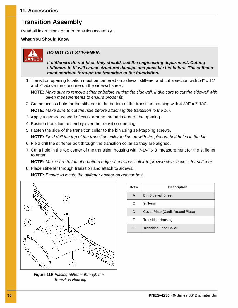
11. Accessories
90 PNEG-4236 40-Series 36' Diameter Bin
Transition AssemblyRead all instructions prior to transition assembly.
What You Should Know
1. Transition opening location must be centered on sidewall stiffener and cut a section with 54" x 11" and 2" above the concrete on the sidewall sheet.
NOTE: Make sure to remove stiffener before cutting the sidewall. Make sure to cut the sidewall with given measurements to ensure proper fit.
2. Cut an access hole for the stiffener in the bottom of the transition housing with 4-3/4" x 7-1/4".
NOTE: Make sure to cut the hole before attaching the transition to the bin.
3. Apply a generous bead of caulk around the perimeter of the opening.
4. Position transition assembly over the transition opening.
5. Fasten the side of the transition collar to the bin using self-tapping screws.
NOTE: Field drill the top of the transition collar to line up with the plenum bolt holes in the bin.
6. Field drill the stiffener bolt through the transition collar so they are aligned.
7. Cut a hole in the top center of the transition housing with 7-1/4" x 8" measurement for the stiffener to enter.
NOTE: Make sure to trim the bottom edge of entrance collar to provide clear access for stiffener.
8. Place stiffener through transition and attach to sidewall.
NOTE: Ensure to locate the stiffener anchor on anchor bolt.
Figure 11R Placing Stiffener through the Transition Housing
DANGERDO NOT CUT STIFFENER.
If stiffeners do not fit as they should, call the engineering department. Cuttingstiffeners to fit will cause structural damage and possible bin failure. The stiffener must continue through the transition to the foundation.
Ref # Description
A Bin Sidewall Sheet
C Stiffener
D Cover Plate (Caulk Around Plate)
F Transition Housing
G Transition Face Collar

11. Accessories
PNEG-4236 40-Series 36' Diameter Bin 91
9. Place washer and nut on anchor bolt and tighten.
NOTE: If optional transition seal kit is not available, then make a plate to seal around the stiffener at the top and bottom of the housing to minimize air loss. Make sure to caulk around the plate before fastening to transition housing.
Seal Kit (Optional)
1. The air deflector included in seal kit may be installed over stiffener at customer’s request.
2. Caulk stiffener/transition cover plates on one side of cover plate along the three straight edges.
3. Place stiffener/transition cover plate on top of transition housing and use the self-drilling screws to fasten cover plate to transition.
4. Repeat this procedure on the inside bottom of the transition housing.
5. The cover plates will need to be trimmed to fit properly on the bottom.
Figure 11S Seal Kit
Ref # Description
A Caulk (on Bottom of the Plate)
B Cover Plate A
C Cover Plate B
NOTE: Trim the cover plate A (B) to fit the boot.

92 PNEG-4236 40-Series 36' Diameter Bin
NOTES

PNEG-4236 40-Series 36' Diameter Bin 93
12. Warranty
GSI Group, LLC Limited WarrantyThe GSI Group, LLC (“GSI”) warrants products which it manufactures to be free of defects in materials and workmanship under normal usage and conditions for a period of 12 months after sale to the original end-user or if a foreign sale, 14 months from arrival at port of discharge, whichever is earlier. The end-user’s sole remedy (and GSI’s only obligation) is to repair or replace, at GSI’s option and expense, products that in GSI’s judgment, contain a material defect in materials or workmanship. Expenses incurred by or on behalf of the end-user without prior written authorization from the GSI Warranty Group shall be the sole responsibility of the end-user.
Warranty Extensions:The Limited Warranty period is extended for the following products:
GSI further warrants that the portable and tower dryer frame and basket, excluding all auger and auger drive components, shall be free from defects in materials for a period of time beginning on the twelfth (12th) month from the date of purchase and continuing until the sixtieth (60th) month from the date of purchase (extended warranty period). During the extended warranty period, GSI will replace the frame or basket components that prove to be defective under normal conditions of use without charge, excluding the labor, transportation, and/or shipping costs incurred in the performance of this extended warranty.
Conditions and Limitations:THERE ARE NO WARRANTIES THAT EXTEND BEYOND THE LIMITED WARRANTY DESCRIPTION SET FORTH ABOVE. SPECIFICALLY, GSI MAKES NO FURTHER WARRANTY OF ANY KIND, EXPRESS OR IMPLIED, INCLUDING, WITHOUT LIMITATION, WARRANTIES OF MERCHANTABILITY OR FITNESS FOR A PARTICULAR PURPOSE OR USE IN CONNECTION WITH: (I) PRODUCT MANUFACTURED OR SOLD BY GSI OR (II) ANY ADVICE, INSTRUCTION, RECOMMENDATION OR SUGGESTION PROVIDED BY AN AGENT, REPRESENTATIVE OR EMPLOYEE OF GSI REGARDING OR RELATED TO THE CONFIGURATION, INSTALLATION, LAYOUT, SUITABILITY FOR A PARTICULAR PURPOSE, OR DESIGN OF SUCH PRODUCTS.
GSI shall not be liable for any direct, indirect, incidental or consequential damages, including, without limitation, loss of anticipated profits or benefits. The sole and exclusive remedy is set forth in the Limited Warranty, which shall not exceed the amount paid for the product purchased. This warranty is not transferable and applies only to the original end-user. GSI shall have no obligation or responsibility for any representations or warranties made by or on behalf of any dealer, agent or distributor.
GSI assumes no responsibility for claims resulting from construction defects or unauthorized modifications to products which it manufactured. Modifications to products not specifically delineated in the manual accompanying the equipment at initial sale will void the Limited Warranty.
This Limited Warranty shall not extend to products or parts which have been damaged by negligent use, misuse, alteration, accident or which have been improperly/inadequately maintained. This Limited Warranty extends solely to products manufactured by GSI.
Prior to installation, the end-user has the responsibility to comply with federal, state and local codes which apply to the location and installation of products manufactured or sold by GSI.
Product Warranty Period
AP Fans and Flooring
Performer Series Direct Drive Fan Motor 3 Years * Warranty prorated from list price:
0 to 3 years - no cost to end-user
3 to 5 years - end-user pays 25%
5 to 7 years - end-user pays 50%
7 to 10 years - end-user pays 75%
** Warranty prorated from list price:
0 to 3 years - no cost to end-user
3 to 5 years - end-user pays 50%
† Motors, burner components and moving parts not included. Portable dryer screens included. Tower dryer screens not included.
All Fiberglass Housings Lifetime
All Fiberglass Propellers Lifetime
AP and Cumberland Flex-Flo/Pan Feeding System Motors 2 Years
Cumberland Feeding/Watering Systems
Feeder System Pan Assemblies 5 Years **
Feed Tubes (1-3/4" and 2.00") 10 Years *
Centerless Augers 10 Years *
Watering Nipples 10 Years *
Grain Systems Grain Bin Structural Design 5 Years
Grain SystemsFarm FansZimmerman
Portable and Tower Dryers 2 Years
Portable and Tower Dryer Frames and Internal Infrastructure †
5 Years
9101239_1_CR_rev8.DOC (revised January 2014)

This equipment shall be installed in accordance with the current installation codes and applicable
regulations, which should be carefully followed in all cases. Authorities having jurisdiction should be
consulted before installations are made.
1004 E. Illinois St. Assumption, IL 62510-0020
Phone: 1-217-226-4421 Fax: 1-217-226-4420
www.gsiag.com
Copyright © 2014 by The GSI Group, LLCPrinted in the USA CN-313460
GSI is a worldwide brand of AGCO Corporation.