Embed Size (px)
Citation preview
Truck Probe
Model: MTP
Installation and Operation Manual
PNEG-2125Version: 1.0
Date: 11-28-16
PNEG-2125

2 PNEG-2125 Truck Probe - Model MTP
All information, illustrations, photos and specifications in this manual are based on the latestinformation available at the time of publication. The right is reserved to make changes at anytime without notice.
Table of Contents
PNEG-2125 Truck Probe - Model MTP 3
ContentsChapter 1 Introduction ..........................................................................................................................................4
General Safety Statements ................................................................................................................... 4Replacement Parts ................................................................................................................................ 4Repair Kits ............................................................................................................................................. 5
Chapter 2 Safety .....................................................................................................................................................6Safety Guidelines .................................................................................................................................. 6Cautionary Symbol Definitions .............................................................................................................. 7Safety Cautions ..................................................................................................................................... 8Safety Sign-Off Sheet ......................................................................................................................... 10
Chapter 3 Decals ..................................................................................................................................................11
Chapter 4 General Information ...........................................................................................................................15System Description ............................................................................................................................. 15Optional Features ................................................................................................................................ 16Material Sampled ................................................................................................................................ 16Truck Probe Construction ................................................................................................................... 16
Chapter 5 Installation ..........................................................................................................................................17Receiving Inspection ........................................................................................................................... 17Pre-Installation Preparation ................................................................................................................. 17Location ............................................................................................................................................... 18General Mounting Guidelines .............................................................................................................. 18Initial Start-Up ..................................................................................................................................... 20Material Sample Transport Lines ........................................................................................................ 20Controller Location .............................................................................................................................. 20System Wiring ..................................................................................................................................... 21Electrical Power Requirements ........................................................................................................... 21System Plumbing ................................................................................................................................ 22
Chapter 6 Operation ............................................................................................................................................23Operators Control Components and their Functions ........................................................................... 23Disconnect Control Components and their Functions ......................................................................... 24Electrical Components ........................................................................................................................ 25Hydraulic Components ........................................................................................................................ 26
Chapter 7 Maintenance and Repair ....................................................................................................................29General Maintenance .......................................................................................................................... 29Periodic Inspection .............................................................................................................................. 29Lubrication ........................................................................................................................................... 30Hydraulic Power Unit Service .............................................................................................................. 30Probe Tip Inspection ........................................................................................................................... 31
Chapter 8 Troubleshooting .................................................................................................................................32General Truck Probe Troubleshooting ................................................................................................ 32Directional Solenoid Valve Troubleshooting ....................................................................................... 32Hydraulic Components Troubleshooting ............................................................................................. 33
Chapter 9 Warranty ..............................................................................................................................................35
4 PNEG-2125 Truck Probe - Model MTP
1. Introduction
This manual covers the installation and operation for the Mega Truck Probe. This manual provides guidelines for installing the product. You must retain a qualified contractor to provide on-site expertise. INTERSYSTEMS IS NOT RESPONSIBLE FOR THE INSTALLATION OF THIS PRODUCT.
InterSystems reserves the right to improve its product whenever possible and practical to do so. We reserve the right to change, improve and modify products at any time without obligation to make changes, improvements and modifications on equipment sold previously.
General Safety Statements
1. The Truck Probe is designed and manufactured with operator safety in mind. However, residual hazards remain due to the nature of material handling and specific material hazards. Use extreme caution at all times.
2. Modifications to equipment may cause extremely dangerous situations that could result in damage to the equipment as well as serious injury or death. Never modify the equipment.
3. InterSystems recommends that you contact the local power company to have a representative survey the installation to ensure wiring is compatible with their system and adequate power is supplied to the unit.
Replacement Parts
The InterSystems, Inc. Truck Probe is a quality built piece of machinery. As with any machine, parts do wear out and fail. It is InterSystems’ recommendation that a small supply of spare parts be kept on hand to cover any minor breakdowns. A separate priced Spare Parts List will be sent identifying the suggested spare parts. It is also necessary to check the certified drawings, which will list any special or custom components utilized on this equipment.
The certified drawings list the non-standard components that have been incorporated into the equipment. InterSystems, Inc. normally stocks non-fabricated parts and non-custom OEM parts. Replacement parts for any other components, including fabricated parts and custom OEM components can be supplied upon request.
For direct parts orders or requests for technical assistance to your sales representative or to:
InterSystems9575 No. 109TH AVEOmaha, NE. 68142Phone: (402) 330-1500FAX: (402) 330-3350
Please have available the MODEL NUMBER, SERIAL NUMBER and CUSTOMER ORDER NUMBER of the equipment in question as well as the location where the Truck Probe is INSTALLED.
1. Introduction
PNEG-2125 Truck Probe - Model MTP 5
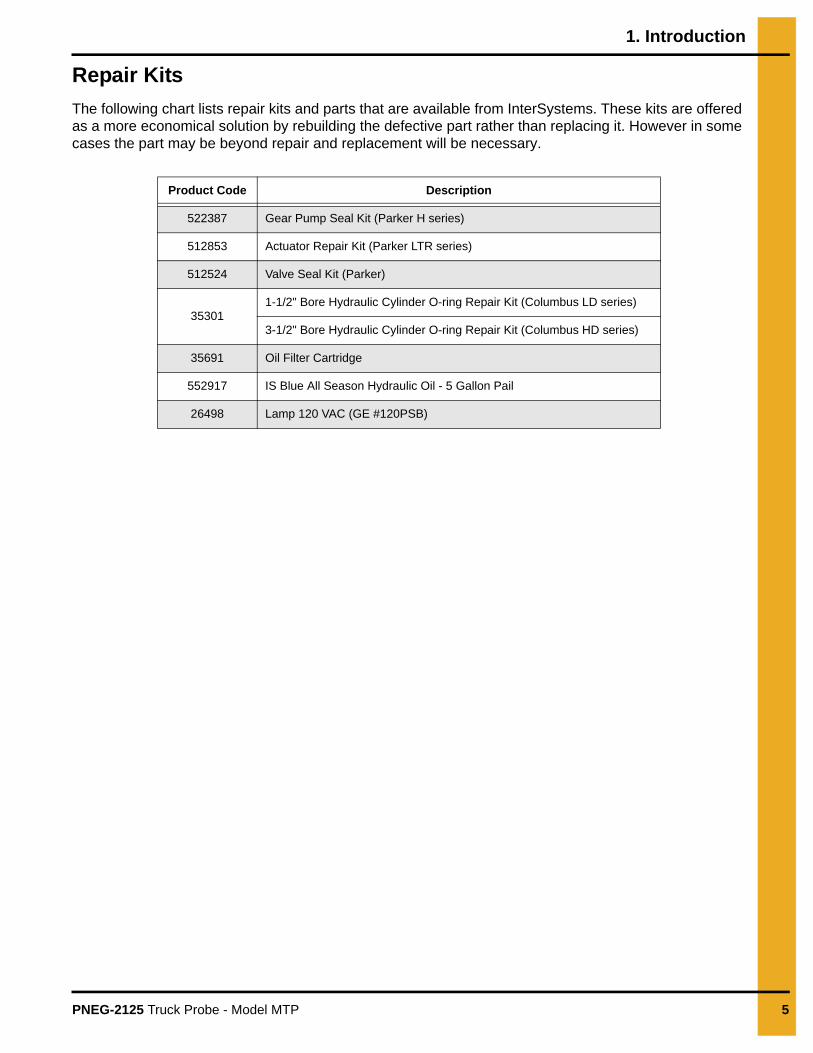
Repair Kits
The following chart lists repair kits and parts that are available from InterSystems. These kits are offered as a more economical solution by rebuilding the defective part rather than replacing it. However in some cases the part may be beyond repair and replacement will be necessary.
Product Code Description
522387 Gear Pump Seal Kit (Parker H series)
512853 Actuator Repair Kit (Parker LTR series)
512524 Valve Seal Kit (Parker)
353011-1/2" Bore Hydraulic Cylinder O-ring Repair Kit (Columbus LD series)
3-1/2" Bore Hydraulic Cylinder O-ring Repair Kit (Columbus HD series)
35691 Oil Filter Cartridge
552917 IS Blue All Season Hydraulic Oil - 5 Gallon Pail
26498 Lamp 120 VAC (GE #120PSB)
6 PNEG-2125 Truck Probe - Model MTP
2. Safety
Safety Guidelines
Safety guidelines are general-to-specific safety rules that must be followed at all times. This manual is written to help you understand safe operating procedures and problems that can be encountered by the operator and other personnel when using this equipment. Save these safety guidelines for future reference.
As owner or operator, you are responsible for understanding the requirements, hazards, and precautions that exist and to inform others as required. Unqualified persons must stay out of the work area at all times.
Alterations must not be made to the equipment. Alterations can produce dangerous situations resulting in SERIOUS INJURY or DEATH.
This equipment must be installed in accordance with the current installation codes and applicable regulations, which must be carefully followed in all cases. Authorities having jurisdiction must be consulted before installations are made.
When necessary, you must consider the installation location relative to electrical, fuel and water utilities.
Personnel operating or working around equipment must read this manual. This manual must be delivered with equipment to its owner. Failure to read this manual and its safety instructions is a misuse of the equipment.
ST-0001-3
2. Safety
PNEG-2125 Truck Probe - Model MTP 7
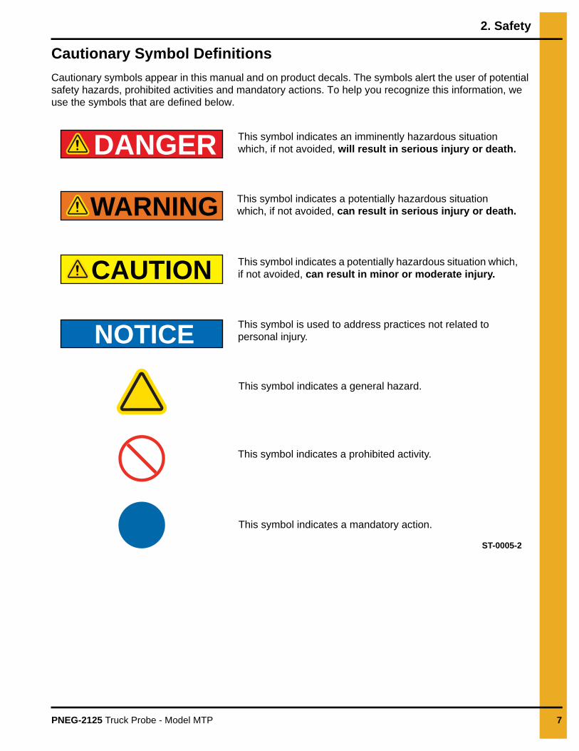
Cautionary Symbol Definitions
Cautionary symbols appear in this manual and on product decals. The symbols alert the user of potential safety hazards, prohibited activities and mandatory actions. To help you recognize this information, we use the symbols that are defined below.
DANGER
WARNING
CAUTION
NOTICE
This symbol indicates an imminently hazardous situation which, if not avoided, will result in serious injury or death.
This symbol indicates a potentially hazardous situation which, if not avoided, can result in serious injury or death.
This symbol indicates a potentially hazardous situation which, if not avoided, can result in minor or moderate injury.
This symbol is used to address practices not related to personal injury.
This symbol indicates a general hazard.
This symbol indicates a prohibited activity.
This symbol indicates a mandatory action.
ST-0005-2
2. Safety
8 PNEG-2125 Truck Probe - Model MTP
Safety Cautions
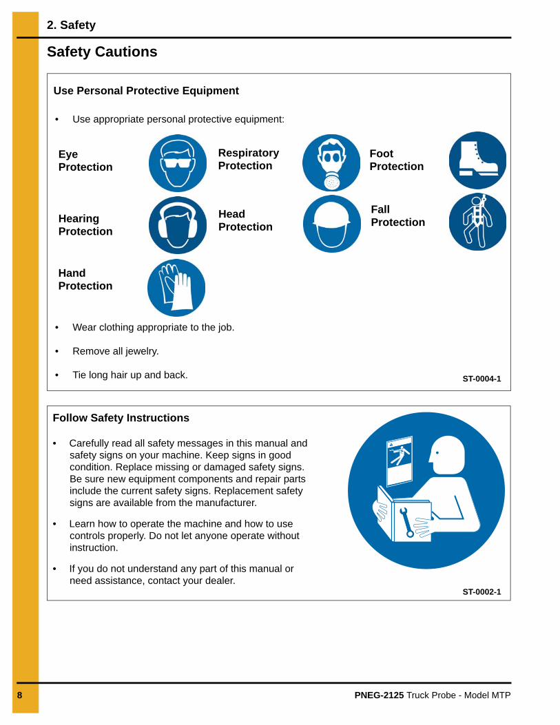
Use Personal Protective Equipment
Eye Protection
Hearing Protection
Hand Protection
Head Protection
Respiratory Protection
Foot Protection
Fall Protection
• Use appropriate personal protective equipment:
• Wear clothing appropriate to the job.
• Remove all jewelry.
• Tie long hair up and back. ST-0004-1
Follow Safety Instructions
• Carefully read all safety messages in this manual and safety signs on your machine. Keep signs in good condition. Replace missing or damaged safety signs. Be sure new equipment components and repair parts include the current safety signs. Replacement safety signs are available from the manufacturer.
• Learn how to operate the machine and how to use controls properly. Do not let anyone operate without instruction.
• If you do not understand any part of this manual or need assistance, contact your dealer.
ST-0002-1
2. Safety
PNEG-2125 Truck Probe - Model MTP 9
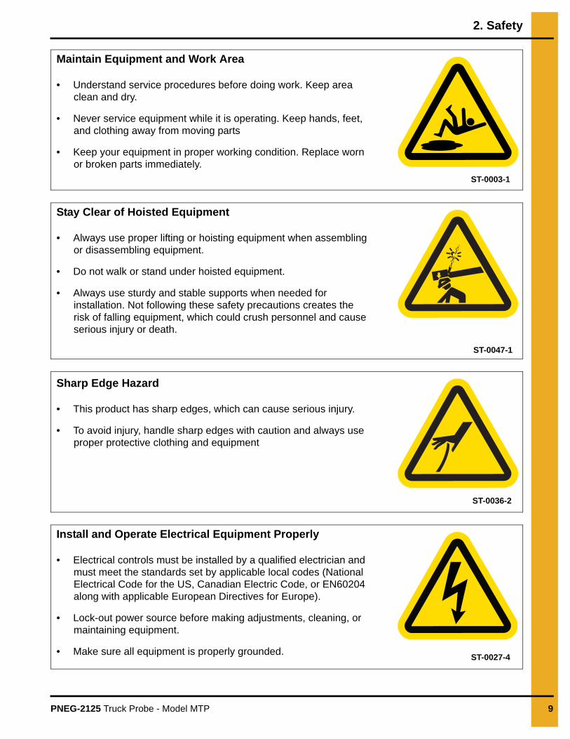
Maintain Equipment and Work Area
• Understand service procedures before doing work. Keep area clean and dry.
• Never service equipment while it is operating. Keep hands, feet, and clothing away from moving parts
• Keep your equipment in proper working condition. Replace worn or broken parts immediately.
ST-0003-1
Stay Clear of Hoisted Equipment
• Always use proper lifting or hoisting equipment when assembling or disassembling equipment.
• Do not walk or stand under hoisted equipment.
• Always use sturdy and stable supports when needed for installation. Not following these safety precautions creates the risk of falling equipment, which could crush personnel and cause serious injury or death.
ST-0047-1
Sharp Edge Hazard
• This product has sharp edges, which can cause serious injury.
• To avoid injury, handle sharp edges with caution and always use proper protective clothing and equipment
ST-0036-2
Install and Operate Electrical Equipment Properly
• Electrical controls must be installed by a qualified electrician and must meet the standards set by applicable local codes (National Electrical Code for the US, Canadian Electric Code, or EN60204 along with applicable European Directives for Europe).
• Lock-out power source before making adjustments, cleaning, or maintaining equipment.
• Make sure all equipment is properly grounded.ST-0027-4
2. Safety
10 PNEG-2125 Truck Probe - Model MTP
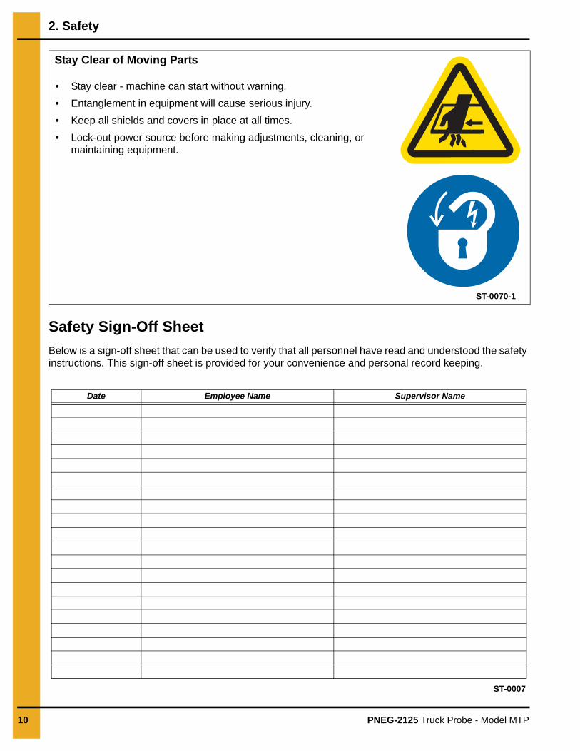
Safety Sign-Off Sheet
Below is a sign-off sheet that can be used to verify that all personnel have read and understood the safety instructions. This sign-off sheet is provided for your convenience and personal record keeping.
Date Employee Name Supervisor Name
Stay Clear of Moving Parts
• Stay clear - machine can start without warning.
• Entanglement in equipment will cause serious injury.
• Keep all shields and covers in place at all times.
• Lock-out power source before making adjustments, cleaning, or maintaining equipment.
ST-0070-1
ST-0007
PNEG-2125 Truck Probe - Model MTP 11
3. Decals
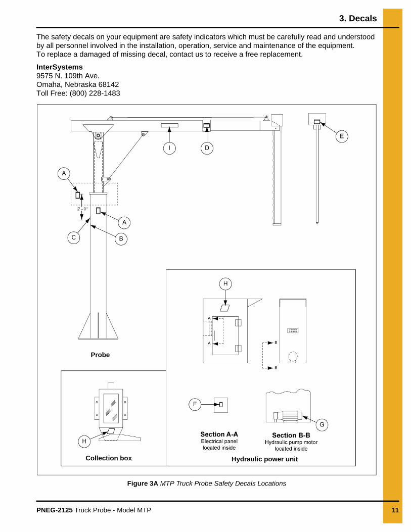
The safety decals on your equipment are safety indicators which must be carefully read and understood by all personnel involved in the installation, operation, service and maintenance of the equipment. To replace a damaged of missing decal, contact us to receive a free replacement.
InterSystems 9575 N. 109th Ave.Omaha, Nebraska 68142 Toll Free: (800) 228-1483
Figure 3A MTP Truck Probe Safety Decals Locations
Probe
Collection box Hydraulic power unit
3. Decals
12 PNEG-2125 Truck Probe - Model MTP
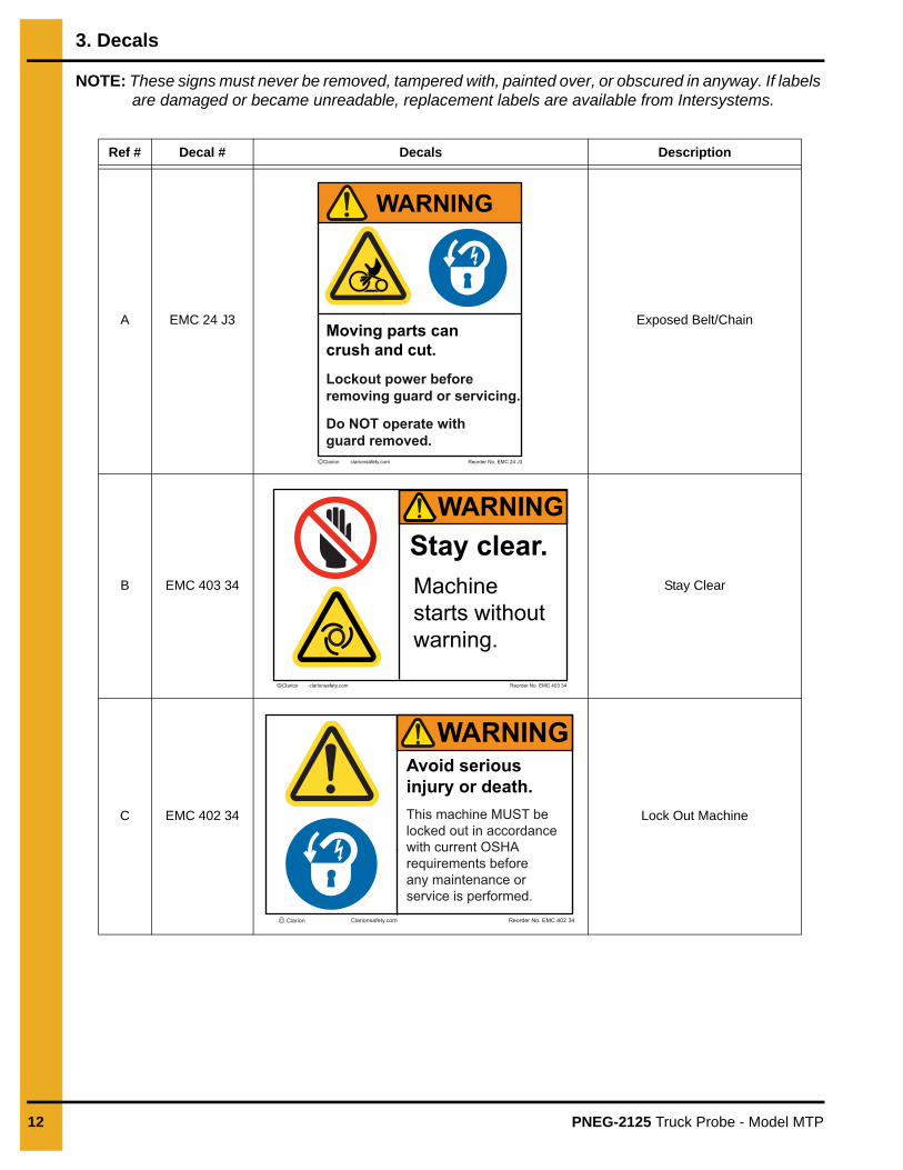
NOTE: These signs must never be removed, tampered with, painted over, or obscured in anyway. If labels are damaged or became unreadable, replacement labels are available from Intersystems.
Ref # Decal # Decals Description
A EMC 24 J3 Exposed Belt/Chain
B EMC 403 34 Stay Clear
C EMC 402 34 Lock Out Machine
WARNING
Moving parts cancrush and cut.
Do NOT operate withguard removed.
Lockout power beforeremoving guard or servicing.
Reorder No. EMC 24 J3 C Clarion clarionsafety.com
WARNINGStay clear.Machine starts withoutwarning.
C Clarion clarionsafety.com Reorder No. EMC 403 34
WARNINGAvoid serious injury or death.This machine MUST be locked out in accordance with current OSHA requirements before any maintenance or service is performed.
Reorder No. EMC 402 34 C Clarion Clarionsafety.com
3. Decals
PNEG-2125 Truck Probe - Model MTP 13
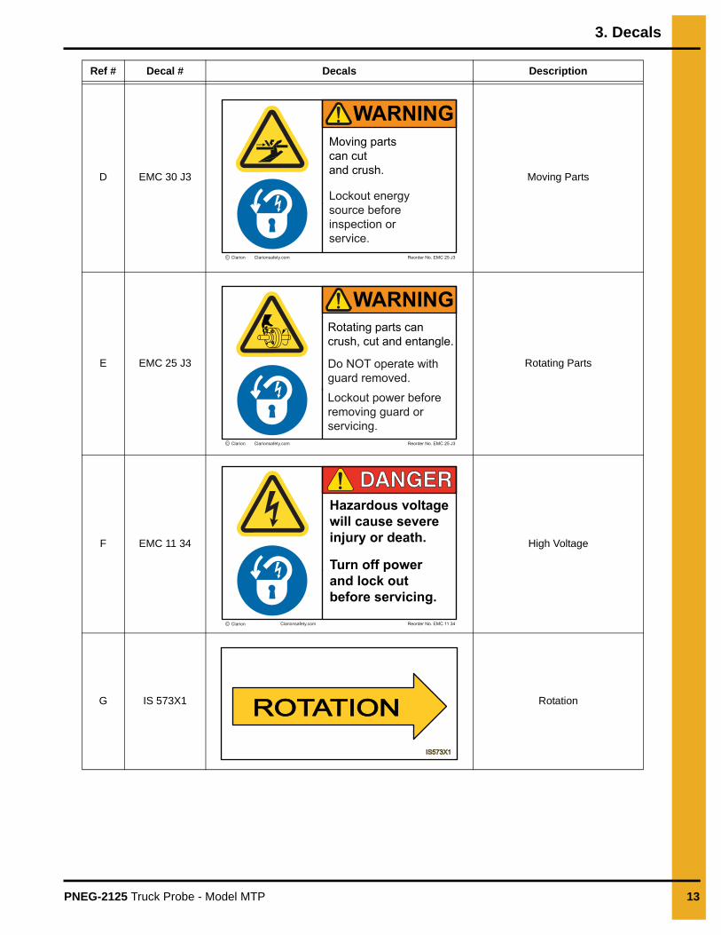
D EMC 30 J3 Moving Parts
E EMC 25 J3 Rotating Parts
F EMC 11 34 High Voltage
G IS 573X1 Rotation
Ref # Decal # Decals Description
WARNINGMoving partscan cutand crush.
Lockout energysource beforeinspection orservice.
Reorder No. EMC 25 J3 C Clarion Clarionsafety.com
WARNINGRotating parts cancrush, cut and entangle.
Do NOT operate withguard removed.
Lockout power beforeremoving guard orservicing.
Reorder No. EMC 25 J3 C Clarion Clarionsafety.com
Hazardous voltagewill cause severe injury or death.
Turn off powerand lock outbefore servicing.
Reorder No. EMC 11 34 C Clarion Clarionsafety.com
DANGERDANGER
IS573X1IS573X1
ROTATIONROTATION
3. Decals
14 PNEG-2125 Truck Probe - Model MTP
H IS 526X4 Intersystems Logo
I IS 5517X4 Intersystems Strip
Ref # Decal # Decals Description
www.intersystems.netwww.intersystems.netOmaha, Nebraska USAOmaha, Nebraska USA
IS52
14X
11IS
5214
X11
OMAHA, NEBRASKA USA
PNEG-2125 Truck Probe - Model MTP 15
4. General Information
System Description
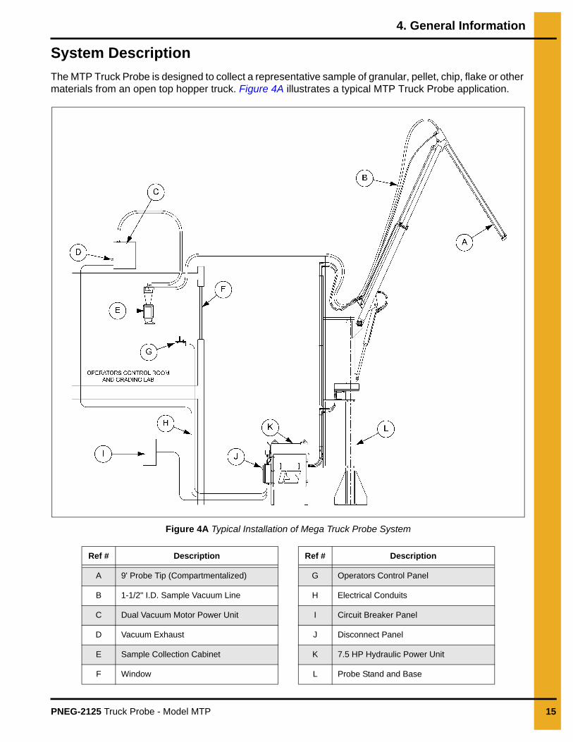
The MTP Truck Probe is designed to collect a representative sample of granular, pellet, chip, flake or other materials from an open top hopper truck. Figure 4A illustrates a typical MTP Truck Probe application.
Figure 4A Typical Installation of Mega Truck Probe System
Ref # Description Ref # Description
A 9' Probe Tip (Compartmentalized) G Operators Control Panel
B 1-1/2" I.D. Sample Vacuum Line H Electrical Conduits
C Dual Vacuum Motor Power Unit I Circuit Breaker Panel
D Vacuum Exhaust J Disconnect Panel
E Sample Collection Cabinet K 7.5 HP Hydraulic Power Unit
F Window L Probe Stand and Base
4. General Information
16 PNEG-2125 Truck Probe - Model MTP
Sample collection is initiated in response to the operator’s manual command generated by controller logic. A sample cycle begins when the operator positions the probe tip for insertion into the truck by rotating the boom and stroking it in or out to the desired sampling position. The vacuum system is turned ON and then the probe tip is inserted down into the hopper truck with the sampling ports closed. The sampling ports are opened to receive a sample and then closed to dump the sample in the vacuum conveying chamber of the probe tip. The probe tip is raised and re-inserted into the material in a different location. This is repeated as required by the FGIS or other regulating guidelines. Once the truck has been properly sampled and sufficient time has elapsed for the sample to be thoroughly conveyed to the collection cabinet, the operator will shut off the vacuum system. The sample can now be emptied from the collection cabinet to be analyzed.
Optional Features
The certified drawings indicate which, if any, optional features are included with a Truck Probe system. Some of the more frequently specified optional features are briefly described in the following list.
Additional optional items that may be furnished if described in the Equipment Quotation and if specifically ordered, may include some or all of the following items:
1. Probe station drive ports
2. Probe station lighting.
3. Probe operation control room or building.
4. Elevated platform with stairway for control station or building.
5. Traffic control lights.
6. Intercom system.
7. Hydraulic tank oil heater.
Material Sampled
Most material from light to heavy density powders, granules, flakes and pellets.
Truck Probe Construction
Standard Truck Probe construction is of painted carbon steel, this includes the base, stand, booms, probe, etc. Other materials and/or finishes appropriate to the operating environment and the material or product being sampled may be used. Refer to the certified drawing(s) for any optional or special components installed on the Truck Probe.
PNEG-2125 Truck Probe - Model MTP 17
5. Installation
Receiving Inspection
1. Carefully inspect the equipment for damage as soon as it is received. Also, verify that the quantity of parts or packages actually received corresponds to the quantity shown on the packing slip. Report any damage or shortage to the delivering carrier as soon as possible.
2. InterSystems responsibility for damage to the equipment ended with acceptance by the delivering carrier. Refer to the bill of lading for more detailed information.
3. Save all paperwork and documentation furnished with any of the Truck Probe components. For example, motor and reducer installation and lubrication instructions, etc.
4. A typical shipment of a standard Truck Probe, without any of the optional items described in material sampled section on Page 16, has five (5) major units:
a. Hydraulic Power Unit
b. Main Stand and Boom Pivot
c. Probe Boom
d. Probe Tip
e. Operators Control Panel, Vacuum Power Unit, Sample Collection Cabinet, Hydraulic Hoses and Fittings Kit, Sample Vacuum Hose, Hydraulic Fluid and Fasteners and Miscellaneous Kit.
NOTE: Anchoring devices and fasteners are not provided.
Pre-Installation Preparation
1. Before starting Truck Probe system installation, study this manual, the certified drawing(s) furnished with the system and other applicable documents (including, but not limited to OSHA Regulations; the National Electrical Code; and all other applicable federal, state and local codes and regulations).
2. InterSystems, Inc. Truck Probes are designed to be self-supporting when securely anchored to a reinforced concrete base constructed as specified by the certified drawing(s). The Truck Probe requires no bracing but it was not designed to support other equipment. Separate support must be provided for any accessory equipment. The user or installer is advised to retain a civil or architectural engineer to plan the overall installation and more specifically, the reinforced concrete bases for the probe itself and the hydraulic power unit.
3. InterSystems, Inc. does not assume turnkey responsibility for the installation. Therefore, the factors presented hereafter for consideration are just that and only that.
a. Before initiating the actual installation process, determine where the probe itself, the sample cabinet, the vacuum box, the control panel and the hydraulic power unit will be situated.
b. As shown on the MTP general data drawing, plan to locate the control panel so that the probe operator has a clear, unobstructed view of the loads to be sampled, so that the operator’s signals to drivers of the loaded vehicles will be seen and understood.
c. The MTP Truck Probe can be set up for single or dual lane operation. The rotation of the boom must be limited to 300° maximum rotation.
d. Plan the routing of the vacuum sampling hose for a minimum of bends and changes in elevation.
5. Installation
18 PNEG-2125 Truck Probe - Model MTP
e. The air exhausted from the vacuum power unit (box) may include dust or other fines from the material being sampled. Plan to exhaust the air to a roof or another location away from pedestrian traffic where the occasional discharge will not be objectionable.
f. Plan the location of the sample collection cabinet. Most often the desired site is at the beginning of the sample grading process in the grain inspection area. If the material other than grain is being sampled, other criteria may apply.
g. Plan the location of the concrete base for the hydraulic power unit. Preferably, it should be located within 4' of the concrete probe base. If the probe is separated from the power unit by more than 4', the user or installer may have to purchase additional hydraulic hose. Maximum separation between the probe and power unit should be held to 10' or less.
h. Excessively long hydraulic hoses can result in pressure loss which in turn results in slow, erratic probe operation. Excessive vacuum hose length can produce low vacuum at the probe tip. The sample collection system may not function properly.
i. It is recommended that guard posts and/or rails be placed around the probe and hydraulic power unit for protection from vehicular traffic.
j. Review all installation plans once more. Double check to be sure that power and communications lines will not be snagged by the probe and also that no conveyors or spouting are routed through the area where the probe is to operate.
Location
The MTP Truck Probe is typically installed near the receiving truck scale and sample lab. (See Figure 4A on Page 15.) Locate the Truck Probe and associated equipment for ease of access and maintenance. The Truck Probe operator should have an unobstructed view of the entire area of boom movement.
The Truck Probe is to be installed only as shown on the certified drawing(s). If an alternate mounting arrangement is desired, contact InterSystems, prior to installation for proper guidance. The Truck Probe is of a general design with modifications specifically for your application. It may be necessary to rework the Truck Probe in order for it to function properly if you alter the application.
General Mounting Guidelines
The Truck Probe assembly is designed to support ONLY its own weight. As shown on the certified drawing, the Truck Probe must be installed on a special concrete foundation. The main stand base has eight (8) clearance holes for securing to the foundation. Refer to the certified drawing(s) of the Truck Probe for the dimensioned locations of these holes.
1. Verify that the concrete probe and power unit bases have cured to develop adequate strength.
2. Position the MTP main stand assembly on the concrete foundation as shown on the certified drawing(s). Install a washer and two (2) nuts on each of the 1.00" diameter anchor bolts. Verify that the main stand is plumb and tighten the anchor nuts.
Truck Probe cannot support any other equipment. Collapse of the whole system can cause death, serious injury and extensive damage to equipment. Properly support all electrical conduits and conveying lines.
5. Installation
PNEG-2125 Truck Probe - Model MTP 19
3. Loosen the bearing set screws on the 1-3/8" diameter boom pivot shaft at the top of the main base assembly and pull the shaft out enough for the boom to be positioned in place. Hoist the boom assembly into position. Re-insert the boom pivot shaft, tighten the bearing set screws and re-install the washer and cotter pin.
4. Remove the up/down cylinder pivot pin from the boom assembly. Cut the shipping strap on theup/down cylinder and attach to the boom assembly. Replace the cylinder pivot pin, washers and cotter pins.
5. Remove the 3/4" diameter nut and bolt from the end of the boom assembly. Position the probe tip assembly and re-install the 3/4" nut and bolt. Install the 1/8" diameter x 1-1/2" long cotter pin, from the hardware kit, into the castle nut.
6. Position the hydraulic bulkhead pipe assembly to the main stand. Use the 3/4" fasteners from the hardware kit.
7. Position the hydraulic power unit assembly at the base of the main stand. Hold the 3'-6" dimension as shown on drawing 530368.
NOTE: The hydraulic power unit is shipped with 15 gallons of fluid already in the reservoir. Another10 gallons of fluid is furnished with the probe and is to be added during initial start-up.
8. Refer to drawing 548613, it calls out the fittings and hoses included in the hose and fitting package. Install the hoses and fittings starting at the hydraulic power unit.
9. Slip the 12" radius steel elbow over the end of the tube protruding from the top of the sample probe tip. Use the U-bolt muffler clamp to secure the elbow to the tube.
10. Slide one end of the blue vacuum hose over the end of the elbow and use the worm screw clamp to secure it. Route the vacuum hose along the length of the open/close hydraulic hoses, from the probe tip actuator to the bulkhead bracket on the outer boom. Tie the vacuum hose and hydraulic hoses to each other using the wire ties. Route the vacuum hose up to the hose saddle on top of the hydraulic piping support. Leave slack in the vacuum hose similar to the hydraulic hoses. Clamp the hose to saddle using two (2) worm screw clamps.
11. Install the 1" x 1-1/2" x 1-1/2" rotational stops. The two (2) stops must be field-welded to the 1" thick top plate of the probe stand beneath the 40 tooth driven sprocket. These stops limit clockwise and counterclockwise (right and left) probe rotation. The probe rotation must be limited to 300°, this will prevent the probe from being swung around and hitting the hydraulic piping support assembly. Reduce the amount of rotation if other obstructions such as buildings, poles, etc. are near by. First lightly tack weld the stops to the plate on top of the probe stand. Then swing the probe through the entire range of travel to verify that it does not hit any obstruction. When proper stop placement is determined, firmly weld the stops in position.
NOTE: When welding the stops, carefully shield the drive sprocket and other drive components from weld spatter.
12. The hydraulic power unit is furnished with the motor starter, valves, tank heater and lock out switch pre-wired into a disconnect enclosure mounted on it. Have a qualified electrician complete the probe field wiring. This includes bring the required power supplies to the panel, wiring to the vacuum motor(s) and wiring to the operators control panel. Refer to the certified electrical drawings.
5. Installation
20 PNEG-2125 Truck Probe - Model MTP
Initial Start-Up1. Turn ON the disconnect switch on the hydraulic power unit control panel.
2. On the operators control panel, turn the HYDRAULIC PUMP switch ON. The hydraulic power unit motor should start, building system pressure. Verify proper hydraulic pump motor rotation. Correct wiring if necessary.
3. Use the joy-sticks to move the probe around. Make sure the air is removed from all hydraulic lines. It may be necessary to loosen a hose where it connects to a cylinder, motor, or actuator to bleed off trapped air.
4. While operating the probe, make sure that the hydraulic and vacuum hoses do not become pinched and are not pulled tight.
5. Adjust the flow control valves which determine the rotational speed (left and right) of the boom. Turn a valve knob counterclockwise to increase fluid flow from a motor port; turn a knob clockwise to reduce flow and slow the motor.
6. After the probe has operated and air has been purged from the system, add hydraulic oil and raise the level up to the top line on the level gauge.
7. Turn the vacuum motor ON and verify proper operation.
Material Sample Transport LinesThe Truck Probe is supplied with 100' of 1-1/2" I.D. flexible sample hose. Route the sample hose from the probe to the collection cabinet along the most direct and shortest path. Avoid tight bends and joints that may become locations that plug. Make all connections airtight and make sure all interior surfaces of joints are smooth and flush. Any ragged or raised tube ends will collect dust and debris as well as retard material flow. Escaping sample material can contaminate surrounding atmosphere and equipment.
Controller Location1. Use vibration isolation pads when mounting the control enclosure or mount the controller in a
vibration-free location.
2. Unless ordered for severe duty, locate controller so it is protected from water and dust.
3. Unless an explosion-proof rated controller was specifically ordered, DO NOT locate the controller in a hazardous area.
4. Most applications require that the Truck Probe be in easy view of the controller.
Hydraulic lines under high pressure, fluid can escape with great velocity. Eye and skin injury may result. Use eye and hand protection when bleeding hydraulic lines.
5. Installation
PNEG-2125 Truck Probe - Model MTP 21
System WiringRefer to the certified electrical drawing(s) for specific wiring requirements. As explained in terminal strip section on Page 24, the terminal strips mounted INSIDE the operator’s control enclosure and the disconnect panel are the connection points for ALL external circuitry.
The controller was completely assembled and tested with the Truck Probe before it left the factory. The electrical installation must comply with OSHA Regulations; the National Electrical Code; and all other applicable federal, state and local codes and regulations.
If wiring between the controller and the Truck Probe unit is run through rigid conduit, use a short length of flexible conduit to connect wiring to the Truck Probe. This will isolate the rigid conduit from any vibration originating in the product conveying line and Truck Probe.
Electrical Power RequirementsRefer to the certified electrical drawing(s) for specific wiring requirements.
Controller
Refer to the certified electrical drawing(s) for specific wiring requirements.
Solenoid Valve Coils
110/120 VAC, 50/60 Hz, Single Phase, 50 Watts.
Optional Hydraulic Tank Heater
120 VAC, 50/60 Hz, Single Phase, 500 Watts.
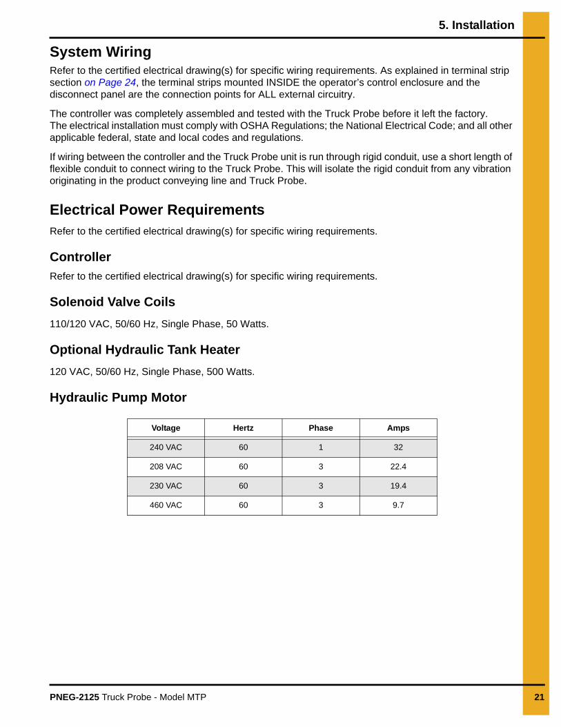
Hydraulic Pump Motor
Voltage Hertz Phase Amps
240 VAC 60 1 32
208 VAC 60 3 22.4
230 VAC 60 3 19.4
460 VAC 60 3 9.7
5. Installation
22 PNEG-2125 Truck Probe - Model MTP
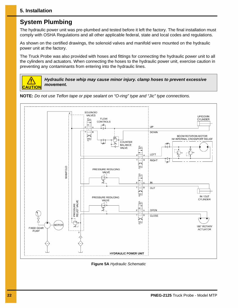
System PlumbingThe hydraulic power unit was pre-plumbed and tested before it left the factory. The final installation must comply with OSHA Regulations and all other applicable federal, state and local codes and regulations.
As shown on the certified drawings, the solenoid valves and manifold were mounted on the hydraulic power unit at the factory.
The Truck Probe was also provided with hoses and fittings for connecting the hydraulic power unit to all the cylinders and actuators. When connecting the hoses to the hydraulic power unit, exercise caution in preventing any contaminants from entering into the hydraulic lines.
NOTE: Do not use Teflon tape or pipe sealant on “O-ring” type and “Jic” type connections.
Figure 5A Hydraulic Schematic
Hydraulic hose whip may cause minor injury. clamp hoses to prevent excessive movement.
PNEG-2125 Truck Probe - Model MTP 23
6. Operation
Operators Control Components and their Functions
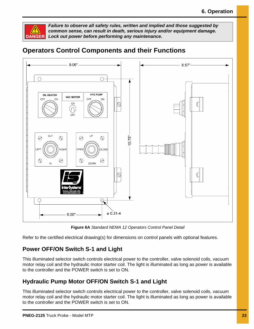
Figure 6A Standard NEMA 12 Operators Control Panel Detail
Refer to the certified electrical drawing(s) for dimensions on control panels with optional features.
Power OFF/ON Switch S-1 and Light
This illuminated selector switch controls electrical power to the controller, valve solenoid coils, vacuum motor relay coil and the hydraulic motor starter coil. The light is illuminated as long as power is available to the controller and the POWER switch is set to ON.
Hydraulic Pump Motor OFF/ON Switch S-1 and Light
This illuminated selector switch controls electrical power to the controller, valve solenoid coils, vacuum motor relay coil and the hydraulic motor starter coil. The light is illuminated as long as power is available to the controller and the POWER switch is set to ON.
Failure to observe all safety rules, written and implied and those suggested by common sense, can result in death, serious injury and/or equipment damage. Lock out power before performing any maintenance.
6. Operation
24 PNEG-2125 Truck Probe - Model MTP
Vacuum Motor OFF/ON Switch S-2
This switch permits the operator to turn ON the vacuum motor when sampling. The motor will need to be turned OFF before opening the collection cabinet door.
Probe Movement Joystick Switches S-3 and S-4
Due to the physical arrangement of the switches on the joy-sticks, only one of the four (4) valve solenoids controlled by each joy-stick can be energized at a given time. As a consequence, two (2) boom/probe motions can be initiated simultaneously. However, if two (2) boom motions are initiated simultaneously, both will occur at a slower rate because of the purposely limited pump capacity. It is much harder to accurately control two (2) boom motions simultaneously.
Oil Heater OFF/ON Switch S-5 and Light
This illuminated selector switch controls electrical power to the tank oil heater. The light is illuminated as long as power is available to the controller and the OIL HEATER switch is set to ON.
Terminal Strip
This 17 position barrier terminal strip is fastened to the sub-plate within the operators control enclosure. It serves as the controller’s interface with and connection point for all external circuits and for the components mounted on the enclosure’s front panel. Refer to the Certified Electrical Drawing(s).
Disconnect Control Components and their Functions
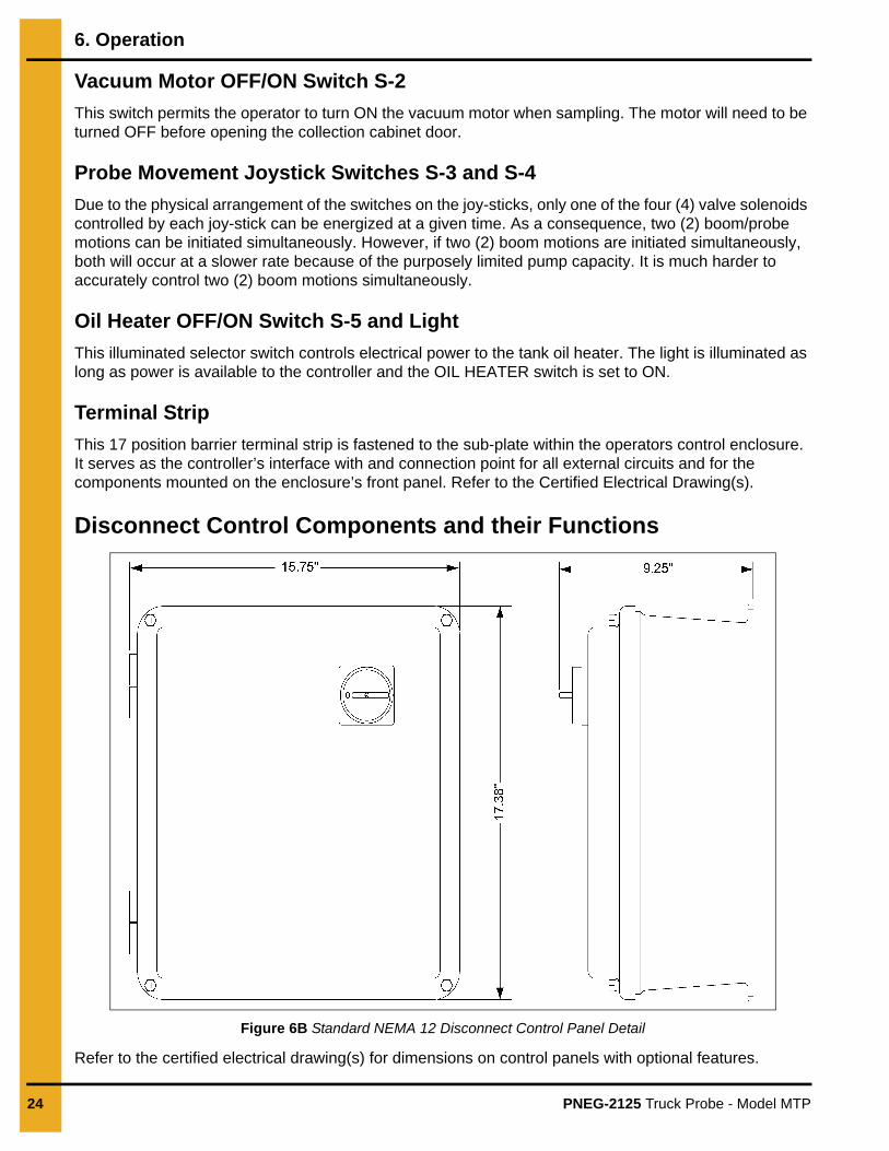
Figure 6B Standard NEMA 12 Disconnect Control Panel Detail
Refer to the certified electrical drawing(s) for dimensions on control panels with optional features.
6. Operation
PNEG-2125 Truck Probe - Model MTP 25
Disconnect Switch
This lockable disconnect switch cuts all electrical power supplies, 1 phase and 3 phase, to the Truck Probe. The enclosure can only be opened with the switch in the OFF position.
Control Fuses
These fuses, located in fuse blocks within the disconnect controller enclosure, protect the controller and probe components against overloads and short circuits.
1. Control fuse 110/120 VAC, 1 PH operation use ONLY a Buss Type FNM, 4 Amp, 250 Volt Slo-Blo fuse or equal.
2. Heater fuse 110/120 VAC, 1 PH operation use ONLY a Buss Type FNM, 8 Amp, 250 Volt Slo-Blo fuse or equal.
Pump Motor Starter and Thermal Overload
This 45 Amp IEC motor starter makes and breaks the power to the hydraulic pump motor. The motor is protected with a set of overload heaters, that sense the motor current and trip if and overload occurs. If the overload trips, it will be necessary to determine the cause and manually reset the overload module inside the disconnect enclosure.
Vacuum Motor(s) Relay
This 25 amp control relay starter makes and breaks the power to the vacuum motor(s).
Terminal Strip(s)
The 35 and 6 position barrier terminal strips are fastened to the sub-plate within the disconnect control enclosure. They serve as the controller’s interface with and connection point for all external circuits. Refer to the Certified Electrical Drawing(s).
Electrical Components
Hydraulic Pump MotorThis motor is coupled to the hydraulic pump via flexible shaft coupling and a pump adapter that bolts to the motor. The motor runs at fixed speed of ~1800 RPM. A label is located on the motor designating the correct direction of rotation. (See Figure 3A on Page 11.) Verify that the motor is turning the proper direction of rotation when wiring the system.
NOTE: Do not run the motor the wrong direction. Damage to the hydraulic pump will result.
Hydraulic Oil HeaterThis immersion heater is mounted in the side of the oil reservoir to heat the oil to a suitable operating temperature. The heater is rated at 500 watts and has in internal thermostat to shut it off at when the oil has been heated. The thermostat should be set at 90°F.
Electrical Safety Interlock SwitchThis switch, mounted on hydraulic power unit, prevents the operators control from functioning. The switch requires a lock key to release the activation key that is chained to the probe stop block. Removal of the activation key cuts power to the operators control panel, thus all shutting down the hydraulic pump motor, hydraulic oil heater, vacuum motor(s) and operators control panel. The probe stop block is to be inserted into an open slot on the probe tip if any work is to be done on the Truck Probe or associated equipment.
6. Operation
26 PNEG-2125 Truck Probe - Model MTP
Vacuum Motor
The vacuum motor(s) are used to create a suction at the probe tip to convey the sample to the collection cabinet. The vacuum motor(s) are only turned during the probing of a truck and must be turned OFF to retrieve the sample from the collection cabinet.
NOTE: Shut the vacuum system off when emptying the collection cabinet. Failure to do so will result mechanical damage to the vacuum motor(s).
Hydraulic Components
Solenoid Valves V-1, V-2, V-3 and V-4
These valves are 4-way, 3-position, double-solenoid operated, spring-centered directional control valves. When both solenoids of a valve are de-energized, the valve spool is spring-centered and hydraulic fluid is routed directly into the manifold’s return passage.
Each solenoid operator also has a manual operator that can be used to physically shift the valve spool. If a valve does not operate when the associated joy-stick is actuated, depressing the manual operator with a ball-point pen or a screwdriver will cause the valve to shift. If the valve shifts, it can be determined that the problem is in electrical circuit or solenoid.
The electrical connections to the solenoids are accessible by removing the cover of the terminal box on each valve. The valves are pre-wired to the disconnect panel on the outside of the hydraulic power unit.
Refer to the certified drawings for additional valve information.
Boom UP/DOWN Valve V-1
This solenoid-operated directional control valve alternately pressurizes the piston end and rod end of the double-acting cylinder to raise and lower the boom. When the valve’s “A” solenoid is energized, the valve spool shifts, pressurizing the piston end of the cylinder, thus raising the boom. When the “B” solenoid is energized, the valve spool shifts, pressurizing the rod end of the cylinder, thus lowering the boom. Note, when neither "A" nor "B" solenoid is energized the valve is spring centered so that all ports are blocked and movement is inhibited.
Boom LEFT/RIGHT Valve V-2
This solenoid-operated directional control valve alternately pressurizes opposing ports of the rotational motor to swing the boom left and right. When the valve’s “A” solenoid is energized, the valve spool shifts, pressurizing the port that swings the boom to the left. When the “B” solenoid is energized, the valve spool shifts, pressurizing the port that swings the boom to the right. Note, when neither “A” nor “B” solenoid is energized the valve is spring centered so that all ports are blocked and movement is inhibited.
Boom IN/OUT Valve V-3
This solenoid-operated directional control valve alternately pressurizes opposing ports of the rotary actuator to rotate the sample clockwise (CW) to collect samples and counterclockwise (CCW) to dump samples (when viewed from the rotary actuator end of the Truck Probe). When the valve’s “A” solenoid is energized, the valve spool shifts, pressurizing the CW port of the actuator. The sample probe rotates, collecting a sample of the material from the product stream. When the “B” solenoid is energized, the valve spool shifts, pressurizing the CCW port of the actuator. The sample probe rotates, dumping the collected sample. Note, when neither “A” nor “B” solenoid is energized the valve is spring centered so that all ports are blocked and movement is inhibited.
6. Operation
PNEG-2125 Truck Probe - Model MTP 27
Sample Ports OPEN/CLOSE Valve V-4 (Compartmentalized Probe Only)
This solenoid-operated directional control valve alternately pressurizes opposing ports of the rotary actuator to rotate the sample ports to collect and dump samples. When the valve’s “A” solenoid is energized, the valve spool shifts, pressurizing the port of the actuator that opens the sample ports. When the “B” solenoid is energized, the valve spool shifts, pressurizing the port of the actuator that closes the sample ports. Note, when neither “A” nor “B” solenoid is energized the valve is spring centered so that all ports are blocked and movement is inhibited.
Boom Left/Right Flow Control Valves V-6, V-7
A pair of in-line flow control valves mounted at the rotational motor, meters the flow of hydraulic fluid out of the rotational motor ports. Refer to the certified drawings. V-6 controls the speed of the boom swing to the left. V-7 controls the speed of the boom swing to the right. The flow controls will need to be adjusted upon initial start-up. To adjust, first loosen the small set screw on the metering screw. Turn clockwise to decrease boom swing speed and counterclockwise to increase boom swing speed. After desired speed is achieved, re-tighten the set screw to lock setting.
NOTE: Avoid excessive boom swing speed, which will result in uncontrollable boom positioning and increased wear and tear on the Truck Probe.
Boom Up/Down Flow Control Valve V-8, V-9
A manifold mounted double flow control valve (sandwiched between the manifold and the counter balance valve V-10), controls the flow of hydraulic fluid to the up/down cylinder. Refer to the certified drawings.V-8 controls the speed the boom raises. V-9 controls the speed the boom lowers. The flow controls will need to be adjusted upon initial start-up. To adjust, first loosen the jam nut on the metering screw. Turn clockwise to decrease boom speed and counterclockwise to increase boom speed. After proper speed is achieved, re-tighten the set screws to lock setting.
NOTE: Avoid excessive Truck Probe speed that will result in increased wear and tear on the Truck Probe. A good indicator of over speeding will be the loud banging of the Truck Probe when reaching its travel limits.
Relief Valve V-5
The relief valve has been set at the factory at 1800 PSI. No further adjustment should be necessary. Check the hydraulic pressure by first opening the gauge shut off valve. If the pump motor is running and the probe operates at all, then the gauge should register some pressure. If it does not, the gauge may be defective. It is normal for the gauge needle to vibrate slightly. Activate the DOWN solenoid. When the boom is all the way down and the DOWN solenoid is still activated the pressure gauge will read the pressure setting at which the relief valve is set.
NOTE: The gauge will last longer if it is not continuously subjected to pump pressure. Close gaugeshut off valve after checking and setting pressure.
To adjust the relief valve setting simply remove the protective cap nut and loosen the lock nut on the valve stem. Use a 1/8" hex key to turn the valve stem clockwise to increase pressure or counterclockwise to reduce pressure. Make valve adjustments in small increments and observe the gauge while doing so. If no change in pressure is noted, the relief valve may be sticking or the gauge may be defective. If the gauge and relief valve have been eliminated as the source of the problem, then the pump may be worn, particularly if the problem is low pressure.
When adjustment is complete, tighten the lock nut to maintain valve adjustment, then tightly re-thread the cap nut onto the valve stem.
6. Operation
28 PNEG-2125 Truck Probe - Model MTP
Pressure Reducing Valves V-10, V-11
These pressure reducing valves have been set at the factory. No further adjustment should be necessary. The IN/OUT valve is set at 1000 PSI. The OPEN/CLOSE valve is set at 750 PSI.
NOTE: A pressure gauge will need to be installed on each of the gauge ports on the pressure reducing valves if adjustments are to be made.
Counter Balance Valve V-12
This counter balance valve has been set at the factory. No further adjustment should be necessary. The valve is set at 500 PSI.
NOTE: A pressure gauge will need to be installed in the gauge port on the counter balance valve if adjustments are to be made.
Hydraulic Cylinders
These double-acting, non-cushioned rod cylinders raise or lower and extend or retract the boom. The up/down cylinder is 3.50 bore x 27 stroke. The in/out cylinder is 1.50 bore x 72 stroke. The cylinders are attached at each end to the boom with a pivot pin. Solenoid valve V-1 controls the up/down movement. Solenoid valve V-3 controls the in/out movement.
Rotary Actuator (Compartmentalized Probe)
The actuator is essentially a double-acting hydraulic cylinder that drives a rack and pinion unit, thus converting linear motion into rotary motion. The actuator is coupled directly to the inner tube of the compartmentalized probe. The rotary actuator opens the sampling ports to receive a sample. When the sampling ports are closed, the sample dumps into the vacuum conveying chamber of the probe. Solenoid valve V-2 controls rotary actuator motions.
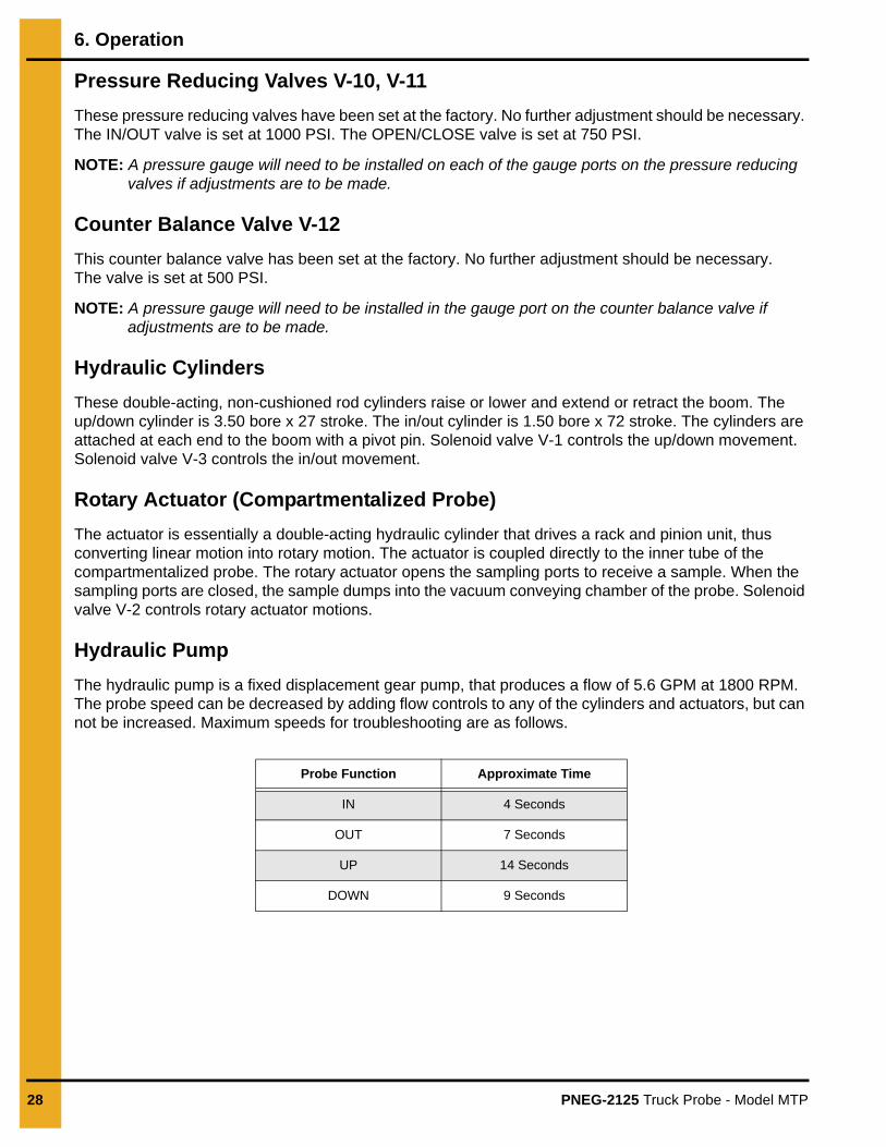
Hydraulic Pump
The hydraulic pump is a fixed displacement gear pump, that produces a flow of 5.6 GPM at 1800 RPM. The probe speed can be decreased by adding flow controls to any of the cylinders and actuators, but can not be increased. Maximum speeds for troubleshooting are as follows.
Probe Function Approximate Time
IN 4 Seconds
OUT 7 Seconds
UP 14 Seconds
DOWN 9 Seconds
PNEG-2125 Truck Probe - Model MTP 29
7. Maintenance and Repair
General Maintenance
A good maintenance program involves thorough general housekeeping, adequate periodic re-lubrication and replacement of worn or damaged components.
Periodic Inspection
At regularly scheduled intervals, while observing all safety precautions, observe the equipment as it operates. Inspect for:
1. Loose or missing hardware.
2. Proper hydraulic oil level.
3. Noisy motors or motor bearings.
4. Structural damage.
5. Rust or corrosion.
6. Damaged wiring, including exposed conductors and connections.
7. Hydraulic leaks, damaged hydraulic lines and components, hoses that are kinked, chaffed or that are binding
8. Excessive dirt accumulation in the hydraulic power unit, vacuum unit, boom pivot and telescoping joints.
9. Vacuum hoses that are kinked or chaffed. Vacuum leaks.
10. Make sure that all guards and warning labels are in place and legible. GENERAL SAFETY INFORMATION from Pages 6-14, explains the purpose and intended location of the warning signs. Warning signs are an important part of any safety program; replace any missing signs IMMEDIATELY.
Failure to observe all safety rules, written and implied and those suggested by common sense, can result in death, serious injury and/or equipment damage.Lock out power before performing any maintenance.
7. Maintenance and Repair
30 PNEG-2125 Truck Probe - Model MTP
Lubrication
Boom Pivoting and Sliding Joints, Monthly
Lubricate all shafts and bearings with a liberal amount of multi-purpose grease. Bearings and shafts should be re-greased monthly. All boom motions should be smooth and constant. Jerky, stick-slip operation may indicate mechanical damage to the boom, to a cylinder, or the rotation motor.
Boom Rotation Drive Chain and Sprockets, Every 6 Months
Because of the operating environment, the boom rotation drive chain and sprockets rapidly accumulate dust and dirt. At the recommended interval, thoroughly flush the chain with an approved solvent to rinse off all accumulated dirt. Then, while the boom is rotating, brush on a coat of lubricant. Be sure to work the lubricant into the chain pin joints.
Hydraulic Power Unit Service
The service intervals are for average operating conditions. More severe conditions such as extreme heat or cold or nearly continuous Truck Probe operation may dictate more frequent service.
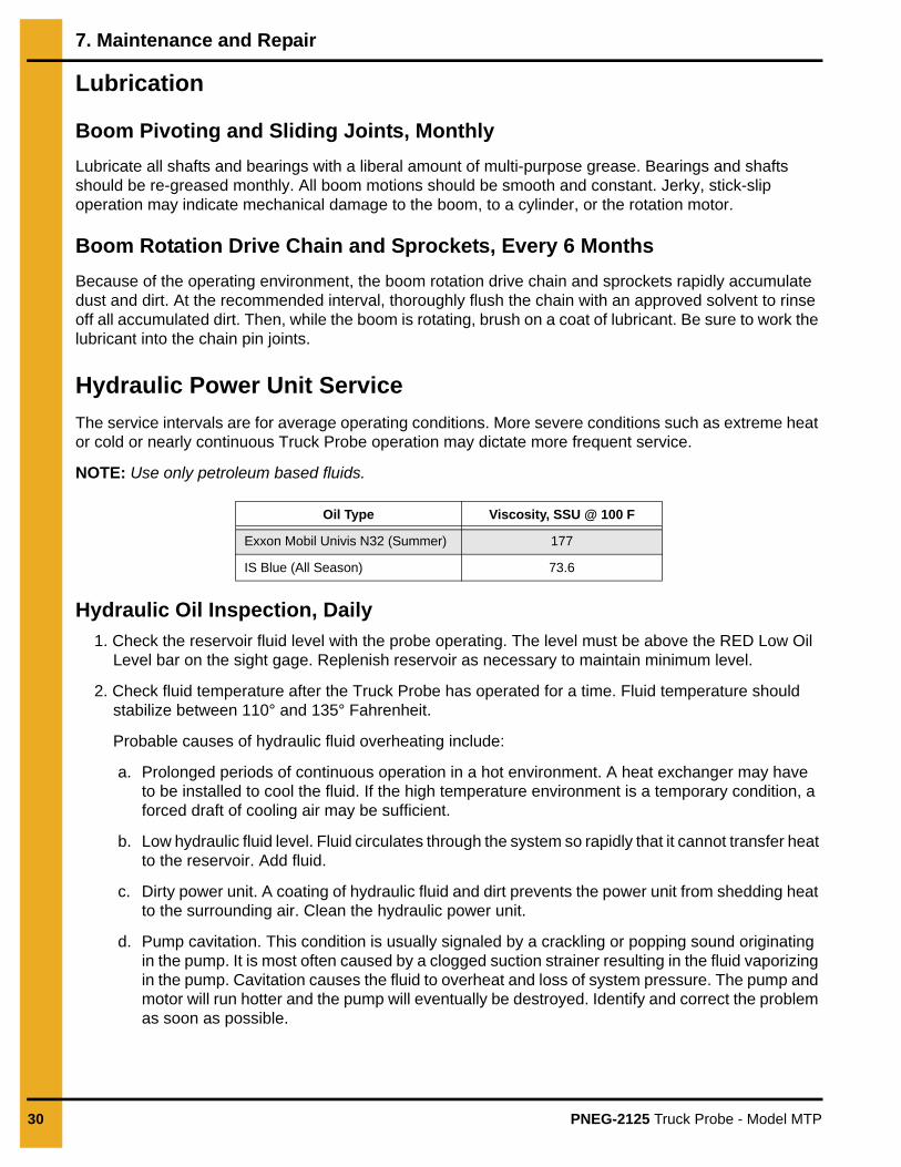
NOTE: Use only petroleum based fluids.
Hydraulic Oil Inspection, Daily
1. Check the reservoir fluid level with the probe operating. The level must be above the RED Low Oil Level bar on the sight gage. Replenish reservoir as necessary to maintain minimum level.
2. Check fluid temperature after the Truck Probe has operated for a time. Fluid temperature should stabilize between 110° and 135° Fahrenheit.
Probable causes of hydraulic fluid overheating include:
a. Prolonged periods of continuous operation in a hot environment. A heat exchanger may have to be installed to cool the fluid. If the high temperature environment is a temporary condition, a forced draft of cooling air may be sufficient.
b. Low hydraulic fluid level. Fluid circulates through the system so rapidly that it cannot transfer heat to the reservoir. Add fluid.
c. Dirty power unit. A coating of hydraulic fluid and dirt prevents the power unit from shedding heat to the surrounding air. Clean the hydraulic power unit.
d. Pump cavitation. This condition is usually signaled by a crackling or popping sound originating in the pump. It is most often caused by a clogged suction strainer resulting in the fluid vaporizing in the pump. Cavitation causes the fluid to overheat and loss of system pressure. The pump and motor will run hotter and the pump will eventually be destroyed. Identify and correct the problem as soon as possible.
Oil Type Viscosity, SSU @ 100 F
Exxon Mobil Univis N32 (Summer) 177
IS Blue (All Season) 73.6
7. Maintenance and Repair
PNEG-2125 Truck Probe - Model MTP 31
Breather Cap Cleaning, Every 3 Months
Remove the breather cap. Wash it thoroughly and blow it dry. Replace the cap.
Hydraulic Filter Replacement, Every 3 Months
Remove and replace the filter canister. A check valve between the filter and the oil reservoir prevents excessive oil spillage during replacement. Check the hydraulic pressure as outlined in relief valve V-5on Page 27.
Hydraulic Oil Inspection, Daily
1. Operate the probe until the fluid temperature has stabilized.
2. Shut off and lock out all power to the probe.
3. Immediately drain the reservoir of fluid. Remove the reservoir cover. It will probably have to be pried off since a bead of silicone sealant was applied at the factory to prevent fluid or vapors from leaking. Use an approved solvent to thoroughly flush any remaining fluid and dirt from the reservoir. DO NOT replace the cover at this time.
4. Disconnect the pressure and suction hoses at the pump to drain any remaining fluid and solvent. Then reconnect the hoses.
5. Make sure the hoses to the Truck Probe are labeled where they connect to the fittings on the end of the power unit. Disconnect the hoses to drain them of fluid. Then reconnect the hoses.
6. Replace the return line filter cartridge.
7. Temporarily remove the suction strainer. Wash it with solvent and blow it dry. Re-install the strainer or replace it if it cannot be cleaned.
8. Remove the breather cap. Wash it with solvent and blow it dry. Replace the breather.
9. Make sure the 1" NPT drain plug is threaded securely in the reservoir drain. Then refill the reservoir with fifteen gallons of approved hydraulic fluid.
10. Operate the Truck Probe until no air bubbles are apparent from the return line.
11. Re-check hydraulic fluid level gauge and add additional oil if required.
12. Wipe the rim of the reservoir and the cover with a solvent-soaked rag, to provide clean, dry sealing surfaces. Apply an even bead of silicone sealant around the rim of the reservoir. Re-install the cover. Sealing the cover to the reservoir is not essential but will help to keep the exterior of the power unit clean and minimize accumulation of dirt.
13. Check the hydraulic pressure as outlined in relief valve V-5 on Page 27.
Probe Tip Inspection
This inspection is best done with the probe lowered near ground level.
1. While keeping the hands clear of the probe, have someone OPEN and CLOSE the probe tip through several cycles sequences. The inner tube should rotate smoothly and evenly within the outer tube.
2. The plastic cap on the end of the probe tip should be in good condition. A damaged cap should be replaced at once; otherwise it will leak, reducing the vacuum drawn in the probe tip.
3. With the probe tip OPEN, the inner tube should be clear and free of any obstructions.
4. The probe tip should pivot freely on the end of the boom without side play.
32 PNEG-2125 Truck Probe - Model MTP
8. Troubleshooting
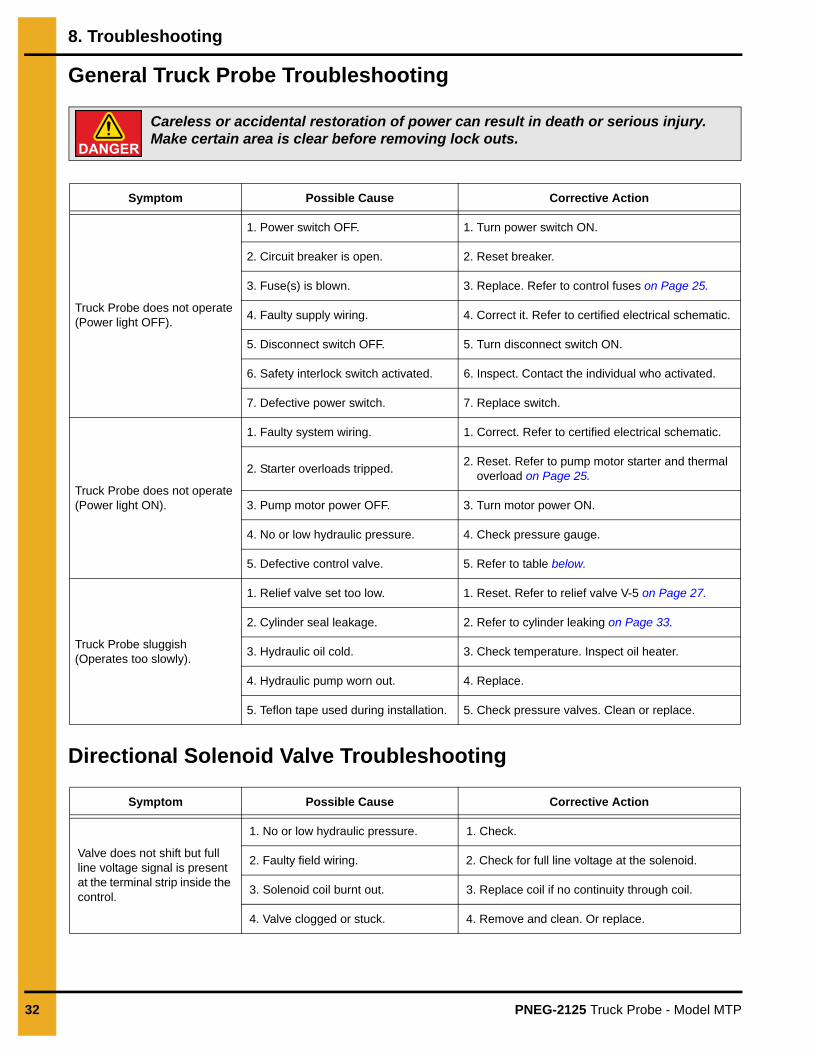
General Truck Probe Troubleshooting
Directional Solenoid Valve Troubleshooting
Symptom Possible Cause Corrective Action
Truck Probe does not operate(Power light OFF).
1. Power switch OFF. 1. Turn power switch ON.
2. Circuit breaker is open. 2. Reset breaker.
3. Fuse(s) is blown. 3. Replace. Refer to control fuses on Page 25.
4. Faulty supply wiring. 4. Correct it. Refer to certified electrical schematic.
5. Disconnect switch OFF. 5. Turn disconnect switch ON.
6. Safety interlock switch activated. 6. Inspect. Contact the individual who activated.
7. Defective power switch. 7. Replace switch.
Truck Probe does not operate(Power light ON).
1. Faulty system wiring. 1. Correct. Refer to certified electrical schematic.
2. Starter overloads tripped.2. Reset. Refer to pump motor starter and thermal
overload on Page 25.
3. Pump motor power OFF. 3. Turn motor power ON.
4. No or low hydraulic pressure. 4. Check pressure gauge.
5. Defective control valve. 5. Refer to table below.
Truck Probe sluggish(Operates too slowly).
1. Relief valve set too low. 1. Reset. Refer to relief valve V-5 on Page 27.
2. Cylinder seal leakage. 2. Refer to cylinder leaking on Page 33.
3. Hydraulic oil cold. 3. Check temperature. Inspect oil heater.
4. Hydraulic pump worn out. 4. Replace.
5. Teflon tape used during installation. 5. Check pressure valves. Clean or replace.
Symptom Possible Cause Corrective Action
Valve does not shift but full line voltage signal is present at the terminal strip inside the control.
1. No or low hydraulic pressure. 1. Check.
2. Faulty field wiring. 2. Check for full line voltage at the solenoid.
3. Solenoid coil burnt out. 3. Replace coil if no continuity through coil.
4. Valve clogged or stuck. 4. Remove and clean. Or replace.
Careless or accidental restoration of power can result in death or serious injury. Make certain area is clear before removing lock outs.
8. Troubleshooting
PNEG-2125 Truck Probe - Model MTP 33
Hydraulic Components Troubleshooting
Cylinder Leaking
1. External Leakage
a. Rod seal leakage can generally be traced to worn or damaged seals. Examine the piston rod for wear or damage. Replace the rod and seals if rod’s surface is rough or worn out-of-round.
2. Internal Leakage
a. The lip seal piston seals are virtually leak free unless they are worn or damaged. Replace defective seals.
b. Contaminants in the hydraulic supply can lead to scored cylinder walls, resulting in rapid seal wear. If such is the case, check to see if the filter is being replaced frequently. A different type of filter may be required; one that can remove finer particles or one that can filter out different kinds of contaminants.
c. Possible piston cylinder leakage, apparently indicated by piston drift is not always traceable to the piston. A leak through a closed valve port can also cause piston drift.

34 PNEG-2125 Truck Probe - Model MTP
NOTES
PNEG-2125 Truck Probe - Model MTP 35
9. Warranty
InterSystems, Inc. reserves the right to make changes in design or in construction of equipment and components without obligation to incorporate such changes in equipment and components previously ordered.
WARRANTY, LIMITATION OF LIABILITY, DISCLAIMER OF IMPLIED WARRANTIES: InterSystems, Inc. manufactured equipment and components are guaranteed against defects in workmanship or materials for one year from date of shipment. The obligation of InterSystems, Inc. with respect to any goods is limited to replacement or repair of defective parts and equipment provided those parts are returned, shipping costs prepaid, to InterSystems' factory and provided the product has not been subject to misuse, negligence, or accident, or repaired or altered outside of our factory, or other than by an Authorized Service Representative. This warranty does not cover the replacement of parts inoperative because of wear occasioned by use, the cost of replacing parts by a person other than an InterSystems employee or an Authorized Service Representative, or the adjustment of a product where the product was improperly adjusted by the purchaser. In addition, this warranty does not cover components manufactured by others such as motors, drives, clutches, cylinders, valves, blowers, and the like. On those components the standard Manufacturers' warranty applies. In any event, liability is limited to the purchase price paid, and InterSystems, Inc. will, under no circumstances, be responsible for special or consequential damages, or for incidental damages.
INTERSYSTEMS, INC. NEITHER MAKES NOR AUTHORIZES ANY WARRANTY OTHER THAN AS HEREIN CONTAINED. THIS WARRANTY IS IN LIEU OF ALL OTHER WARRANTIES, EXPRESS OR IMPLIED, INCLUDING
THOSE OF MERCHANTABILITY AND FITNESS FOR A PARTICULAR PURPOSE.

This equipment shall be installed in accordance with the current installation codes and applicable
regulations, which should be carefully followed in all cases. Authorities having jurisdiction should be
consulted before installations are made.
InterSystems
9575 N. 109th Ave.Omaha, Nebraska 68142Toll Free: (800) 228-1483
www.gsiag.com
Copyright © 2016 by Intersystems, Inc.Printed in the USA CN-326830
InterSystems is a part of GSI, a worldwide brand of AGCO Corporation.