Embed Size (px)
Citation preview
TYPE P
AC100V/200V
M0007857B
PB3A003P201/202
CLOSED LOOP STEPPING SYSTEM
Instruction Manual

Preface
Shipping the product This product in this instruction manual corresponds with the shipping regulations given in the Export Trade Control Ordinance (Table 1, item 16). When these products are exported by customers, it is recommended to fulfill the requirements of export procedure with the relevant authorities, as well as “Information Requirements” and “Objective Requirements” according to the Catch-all regurations.
Feature outline
This manual outlines the functions, wiring, installation, operations, maintenance, specifications, etc. of the Closed Loop Stepping System Model No.PB.
“Model No. PB Series”was born as a new, intelligent, and easy to handle closed loop stepping
system which the technology of design and production in précised compact motor with high
performance is in harmony with up-to-date control technology. This is a system which controls according to the command of upper controller. Especially in minor stroke and high-hitrate operation, this has higher response of
acceleration/deceleration than the servo system in the same size. The moving command unit may be selected from 500, 1000, 2000, 4000, 5000 and 10000. Since this has its unique stopping holding torque, slight vibration is not caused as usual servos
has. Precautions related to this Instruction Manual ・ In order to fully understand the functions of Closed Loop Stepping System Model No.PB,
please read this instruction manual thoroughly before use. ・ Please contact the dealre or sales representative if there are defects such as nonconsecutive
pages, missing pages or if the manual is lost or damaged. ・ Carefully and completely follow the safety instructions outlined in this manual. Please note
that safety is not guaranteed for usage methods other than those specified in this manual or usage methods intended for the original product.
・ The contents of this manual may be modified without prior notice, as revisions or additions are made in the usage method of this product. Modifications are performed per the revisions of this manual.
・ Permission is granted to reproduce or omit part of the attached figures (as abstracts) for use. ・ Although the manufacturer has taken all possible measures to ensure the veracity of the
contents of this manual, if you should notice any error or ommission, please notify the dealer or sales office of the finding.
Related instructions manual
Refer to M0007856 for the specification of the PC interface software.
Contents
1. Safety Precautions
1. 1 Introduction ・・・・・・・・・・・・ 1-1 1. 2 Location of warning labels on the product ・・・・・・・・・・・・・ 1-1 1. 3 Explanation about Indications ・・・・・・・・・・・・・・・・・・・・・・・ 1-2 1. 4 Caution when Using ・・・・・・・・・・・・・・・・・・・・・・・・・・・・・・・・ 1-3
2. Model Number Nomenclature
2. 1 Verifying Package Contents ・・・・・・・・・・・・・・・・・・・・・・・・ 2-1 2. 2 Model number Nomenclature ・・・・・・・・・・・・・・・・・・・・・・・・・ 2-1 2. 3 Motor Model Combination Table ・・・・・・・・・・・・・・・・・・・・・・・ 2-3
3. Installation・Wiring
3. 1 External wiring diagram ・・・・・・・・・・・・・・・・・・・・・・・・・・・・・・・ 3-1 3. 2 Part Names and Functions ・・・・・・・・・・・・・・・・・・・・・・・・・・・・ 3-2 3. 3 Installation ・・・・・・・・・・・・・・・・・・・・・・・・・・・・・・・・・・・・・・・・ 3-3 3. 4 Wiring ・・・・・・・・・・・・・・・・・・・・・・・・・・・・・・・・・・・・・・・・・・・・ 3-5 3.4.1 Wiring Precautions ・・・・・・・・・・・・・・・・・・・・・・・・・・・・・・・・・・・・ 3-5
3.4.2 External Installation Wiring Diagram ・・・・・・・・・・・・・・・・・・・・・・・・ 3-5 3.4.3 Connector Model Numbers and Appropriate Electric Wires ・・・・ 3-6 3.4.4 Connector Pin Assignment ・・・・・・・・・・・・・・・・・・・・・・・・・・・・・・・・ 3-7 3.4.5 Grounding ・・・・・・・・・・・・・・・・・・・・・・・・・・・・・・・・・・・・・・・・・・・・・・ 3-8 3.4.6 Short-circuit Breaker ・・・・・・・・・・・・・・・・・・・・・・・・・・・・・・・・・ ・・・・ 3-8 3.4.7 Motor and Encoder Wiring ・・・・・・・・・・・・・・・・・・・・・・・・ ・・・・ 3-8 3.4.8 Power Wiring ・・・・・・・・・・・・・・・・・・・・・・・・・・・・・・・・・・・・・・・ ・・・・ 3-8 3.4.9 Control Input / Output Signal Wiring ・・・・・・・・・・・・・・・・・・・・・・・ 3-9
4. Input/Output Signal Functions
4. 1 Input / Output Control Signal Functions ・・・・・・・・・・・・・・・・・ 4-1 4. 2 Switch Settings ・・・・・・・・・・・・・・・・・・・・・・・・・・・・・・・・・・・・ 4-7 4. 3 Display ・・・・・・・・・・・・・・・・・・・・・・・・・・・・・・・・・・・・・・・・・・・・・ 4-11 4. 4 ALM Detection Function ・・・・・・・・・・・・・・・・・・・・・・・・・・・・・・ 4-11 4. 5 Amplifier Status Change Diagram ・・・・・・・・・・・・・・・・・・・・・・ 4-16
5. Commands
5. 1 Command ・・・・・・・・・・・・・・・・・・・・・・・・・・・・・・・・・・・・・・・・・ 5-1 5.1.1 Command List ・・・・・・・・・・・・・・・・・・・・・・・・・・・・・・・・・・・・・・・・ 5-1 5.1.2 Commands ・・・・・・・・・・・・・・・・・・・・・・・・・・・・・・・・・・・・・・・・・ 5-3
6. Specification
6. 1 Amplifier Basic Specifications ・・・・・・・・・・・・・・・・・・・・・・・・ 6-1 6. 2 Motor Standard Specifications ・・・・・・・・・・・・・・・・・・・・・・・・ 6-2 6. 3 Motor Option Specifications ・・・・・・・・・・・・・・・・・・・・・・・・・・ 6-3 6. 4 Velocity – Torque, power consumption characteristics ・・・ 6-5
6. 5 Outline Drawings ・・・・・・・・・・・・・・・・・・・・・・・・・・・・・・・・・・・・ 6-7 6.5.1 Amplifier Drawing ・・・・・・・・・・・・・・・・・・・・・・・・・・・・・・・・・・・・・・ 6-7 6.5.2 Motor Drawings ・・・・・・・・・・・・・・・・・・・・・・・・・・・・・・・・・・・・・・・・ 6-8
7. Options
7. 1 Optional Cables ・・・・・・・・・・・・・・・・・・・・・・・・・・・・・・・・・・ 7-1 7. 2 Optional Connectors ・・・・・・・・・・・・・・・・・・・・・・・・・・・・・・・・・・・・ 7-4 7. 3 Optional Communication Equipment ・・・・・・・・・・・・・・・・・・・ 7-5
8. International Standards Conformity
8. 1 International Standards Conformity ・・・・・・・・・・・・・・・・・・・・・・ 8-1 8. 2 Low voltage command ・・・・・・・・・・・・・・・・・・・・・・・・ 8-1 8. 3 EMC Directive ・・・・・・・・・・・・・・・・・・・・・・・・・・・・・・・・・ 8-2
1.Safety Precautions (common)
1-1
1.1 Introduction The PB system is designed for use in general manufacturing equipment. Please observe the following instructions: ・ Read this User Manual carefully before any installation or assembly, to ensure proper use. ・ Do not perform any retrofitting or modification of the product. ・ Consult with a sales representative or a qualified technician regarding installation and maintenance. ・ Special considerations, such as redundant services or an emergency generator are required when
operating, maintaining and/or controlling devices in the following applications. Contact our office if:
① The device is used in medical instruments used for life support. ② The device is used in trains or elevators, the failure of which could cause bodily injury. ③ The device is used in computer systems of social or public importance. ④ The device is used in any equipment related to human safety or public infrastructure.
・ Please contact our office if the device is to be used in an environment where vibration is present, such as in-vehicle or transport applications.
Before installing, operating, performing maintenance or inspecting this device, read this entire manual carefully to ensure proper use. Use this device only after learning about the device, its safety information and the precautions related to its use. After reading this User Manual, keep it in a place where it is always visible to the user.
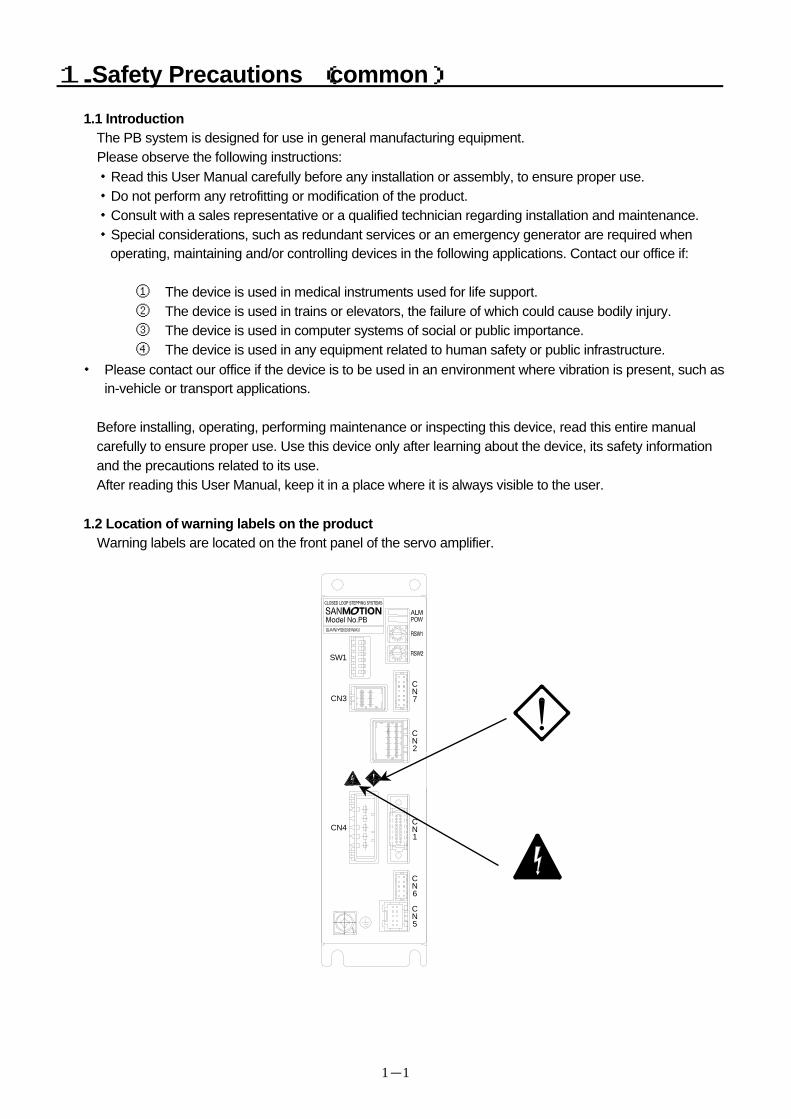
1.2 Location of warning labels on the product Warning labels are located on the front panel of the servo amplifier.
SW1
CN4
CN3N
N
N
N
C
C
C
C
7
1
2
5
NC
6
1.Safety Precautions (common)
1-2
1.3 Explanation about Indications
This chapter explains the following precautions. Be sure of conventions of indications before continuing on to Section 1.3.
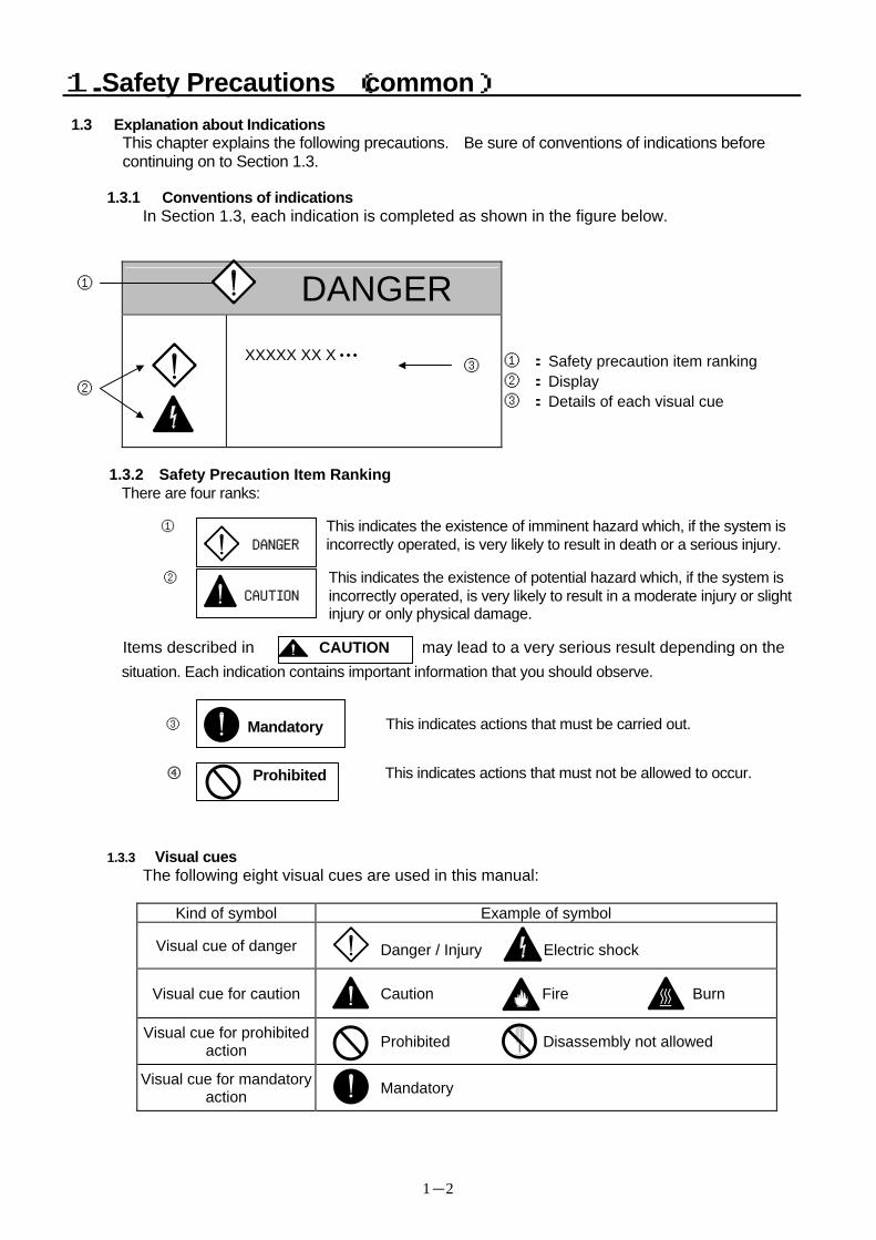
1.3.1 Conventions of indications
In Section 1.3, each indication is completed as shown in the figure below.
DANGER
XXXXX XX X・・・
① : Safety precaution item ranking ② : Display ③ : Details of each visual cue
②
③
①
1.3.2 Safety Precaution Item Ranking
There are four ranks: ① This indicates the existence of imminent hazard which, if the system is
incorrectly operated, is very likely to result in death or a serious injury. ② This indicates the existence of potential hazard which, if the system is
incorrectly operated, is very likely to result in a moderate injury or slight injury or only physical damage.
Items described in CAUTION may lead to a very serious result depending on the situation. Each indication contains important information that you should observe.
③ This indicates actions that must be carried out.
④ This indicates actions that must not be allowed to occur.
1.3.3 Visual cues
The following eight visual cues are used in this manual:
Kind of symbol Example of symbol
Visual cue of danger
Danger / Injury Electric shock
Visual cue for caution
Caution Fire Burn
Visual cue for prohibited action Prohibited Disassembly not allowed
Visual cue for mandatory action Mandatory
Mandatory
Prohibited
CAUTION
DANGER
1.Safety Precautions (common)
1-3
1.4 Safety Precautions
Danger
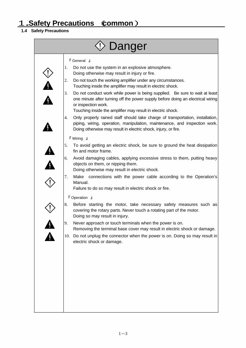
『 General 』
1. Do not use the system in an explosive atmosphere. Doing otherwise may result in injury or fire.
2. Do not touch the working amplifier under any circumstances. Touching inside the amplifier may result in electric shock.
3. Do not conduct work while power is being supplied. Be sure to wait at least one minute after turning off the power supply before doing an electrical wiring or inspection work. Touching inside the amplifier may result in electric shock.
4. Only properly rained staff should take charge of transportation, installation, piping, wiring, operation, manipulation, maintenance, and inspection work. Doing otherwise may result in electric shock, injury, or fire.
『 Wiring 』
5. To avoid getting an electric shock, be sure to ground the heat dissipation fin and motor frame.
6. Avoid damaging cables, applying excessive stress to them, putting heavy objects on them, or nipping them. Doing otherwise may result in electric shock.
7. Make connections with the power cable according to the Operation’s Manual. Failure to do so may result in electric shock or fire.
『 Operation 』
8. Before starting the motor, take necessary safety measures such as covering the rotary parts. Never touch a rotating part of the motor. Doing so may result in injury.
9. Never approach or touch terminals when the power is on. Removing the terminal base cover may result in electric shock or damage.
10. Do not unplug the connector when the power is on. Doing so may result in electric shock or damage.
1.Safety Precautions (common)
1-4
Caution
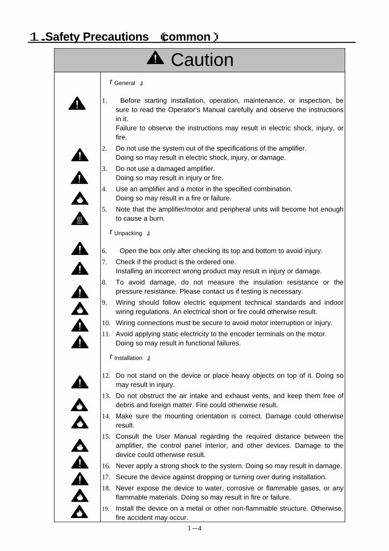
『 General 』
1. Before starting installation, operation, maintenance, or inspection, be sure to read the Operator’s Manual carefully and observe the instructions in it. Failure to observe the instructions may result in electric shock, injury, or fire.
2. Do not use the system out of the specifications of the amplifier. Doing so may result in electric shock, injury, or damage.
3. Do not use a damaged amplifier. Doing so may result in injury or fire.
4. Use an amplifier and a motor in the specified combination. Doing so may result in a fire or failure.
5. Note that the amplifier/motor and peripheral units will become hot enough to cause a burn.
『 Unpacking 』
6. Open the box only after checking its top and bottom to avoid injury. 7. Check if the product is the ordered one.
Installing an incorrect wrong product may result in injury or damage. 8. To avoid damage, do not measure the insulation resistance or the
pressure resistance. Please contact us if testing is necessary. 9. Wiring should follow electric equipment technical standards and indoor
wiring regulations. An electrical short or fire could otherwise result. 10. Wiring connections must be secure to avoid motor interruption or injury. 11. Avoid applying static electricity to the encoder terminals on the motor.
Doing so may result in functional failures. 『 Installation 』
12. Do not stand on the device or place heavy objects on top of it. Doing so may result in injury.
13. Do not obstruct the air intake and exhaust vents, and keep them free of debris and foreign matter. Fire could otherwise result.
14. Make sure the mounting orientation is correct. Damage could otherwise result.
15. Consult the User Manual regarding the required distance between the amplifier, the control panel interior, and other devices. Damage to the device could otherwise result.
16. Never apply a strong shock to the system. Doing so may result in damage.17. Secure the device against dropping or turning over during installation. 18. Never expose the device to water, corrosive or flammable gases, or any
flammable materials. Doing so may result in fire or failure. 19. Install the device on a metal or other non-flammable structure. Otherwise,
fire accident may occur.
1. (common) Safety Precautions
1-5
Caution
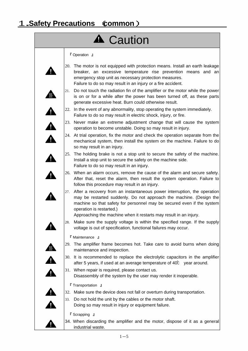
『 Operation 』
20. The motor is not equipped with protection means. Install an earth leakage breaker, an excessive temperature rise prevention means and an emergency stop unit as necessary protection measures. Failure to do so may result in an injury or a fire accident.
21. Do not touch the radiation fin of the amplifier or the motor while the power is on or for a while after the power has been turned off, as these parts generate excessive heat. Burn could otherwise result.
22. In the event of any abnormality, stop operating the system immediately. Failure to do so may result in electric shock, injury, or fire.
23. Never make an extreme adjustment change that will cause the system operation to become unstable. Doing so may result in injury.
24. At trial operation, fix the motor and check the operation separate from the mechanical system, then install the system on the machine. Failure to do so may result in an injury.
25. The holding brake is not a stop unit to secure the safety of the machine. Install a stop unit to secure the safety on the machine side. Failure to do so may result in an injury.
26. When an alarm occurs, remove the cause of the alarm and secure safety. After that, reset the alarm, then result the system operation. Failure to follow this procedure may result in an injury.
27. After a recovery from an instantaneous power interruption, the operation may be restarted suddenly. Do not approach the machine. (Design the machine so that safety for personnel may be secured even if the system operation is restarted.) Approaching the machine when it restarts may result in an injury.
28. Make sure the supply voltage is within the specified range. If the supply voltage is out of specification, functional failures may occur.
『 Maintenance 』
29. The amplifier frame becomes hot. Take care to avoid burns when doing maintenance and inspection.
30. It is recommended to replace the electrolytic capacitors in the amplifier after 5 years, if used at an average temperature of 40 year around.
31. When repair is required, please contact us. Disassembly of the system by the user may render it inoperable.
『 Transportation 』
32. Make sure the device does not fall or overturn during transportation. 33. Do not hold the unit by the cables or the motor shaft.
Doing so may result in injury or equipment failure. 『 Scrapping 』
34. When discarding the amplifier and the motor, dispose of it as a general industrial waste.
1.Safety Precautions (common)
1-6
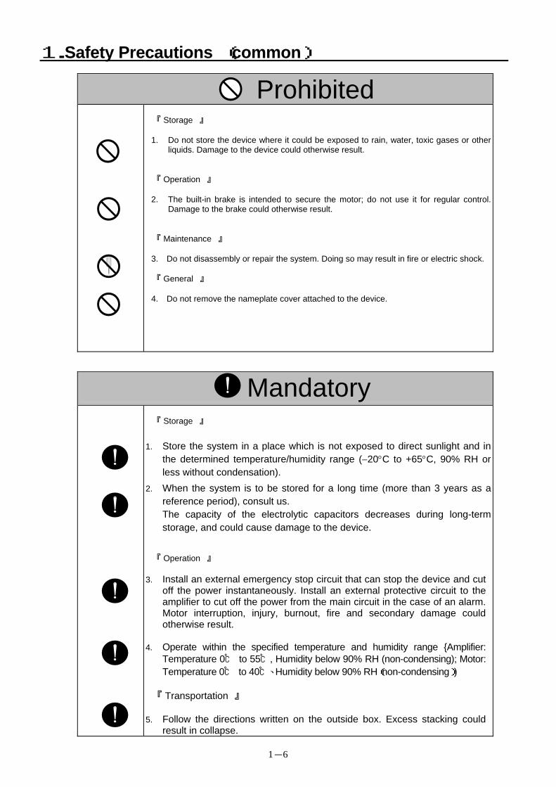
Prohibited
『 Storage 』
1. Do not store the device where it could be exposed to rain, water, toxic gases or other liquids. Damage to the device could otherwise result.
『 Operation 』
2. The built-in brake is intended to secure the motor; do not use it for regular control. Damage to the brake could otherwise result.
『 Maintenance 』 3. Do not disassembly or repair the system. Doing so may result in fire or electric shock.
『 General 』 4. Do not remove the nameplate cover attached to the device.
Mandatory
『 Storage 』
1. Store the system in a place which is not exposed to direct sunlight and in the determined temperature/humidity range (−20°C to +65°C, 90% RH or less without condensation).
2. When the system is to be stored for a long time (more than 3 years as a reference period), consult us. The capacity of the electrolytic capacitors decreases during long-term storage, and could cause damage to the device.
『 Operation 』
3. Install an external emergency stop circuit that can stop the device and cut off the power instantaneously. Install an external protective circuit to the amplifier to cut off the power from the main circuit in the case of an alarm. Motor interruption, injury, burnout, fire and secondary damage could otherwise result.
4. Operate within the specified temperature and humidity range Amplifier:
Temperature 0 to 55, Humidity below 90% RH (non-condensing); Motor: Temperature 0 to 40、Humidity below 90% RH(non-condensing))
『 Transportation 』
5. Follow the directions written on the outside box. Excess stacking could result in collapse.
2. Model Number Nomenclature
2-1
2. 1 Verifying Package Contents Verify the following items when the product arrives. If any discrepancies are noticed, contact our office.
・ Verify that the model number is the same as ordered (model number is located on the main name plate).
・ Verify that there are no defects, such as damage to the exterior of the device.
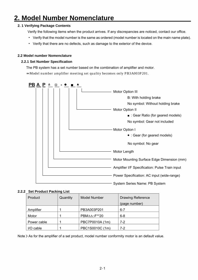
2.2 Model number Nomenclature 2.2.1 Set Number Specification
The PB system has a set number based on the combination of amplifier and motor. *Model number amplifier meeting set quality becomes only PB3A003P201. PB A P -
Motor Option III
B: With holding brake
No symbol: Without holding brake
Motor Option II : Gear Ratio (for geared models)
No symbol: Gear not included
Motor Option I : Gear (for geared models)
No symbol: No gear
Motor Length
Motor Mounting Surface Edge Dimension (mm)
Amplifier I/F Specification: Pulse Train input
Power Specification: AC input (wide-range)
System Series Name: PB System
2.2.2 Set Product Packing List
Product Quantity Model Number Drawing Reference
(page number)
Amplifier 1 PB3A003P201 6-7
Motor 1 PBM∆∆F**20 6-8
Power cable 1 PBC7P0010A (1m) 7-2
I/O cable 1 PBC1S0010C (1m) 7-2
Note)As for the amplifier of a set product, model number conformity motor is an default value.
2. Model Number Nomenclature
2-2
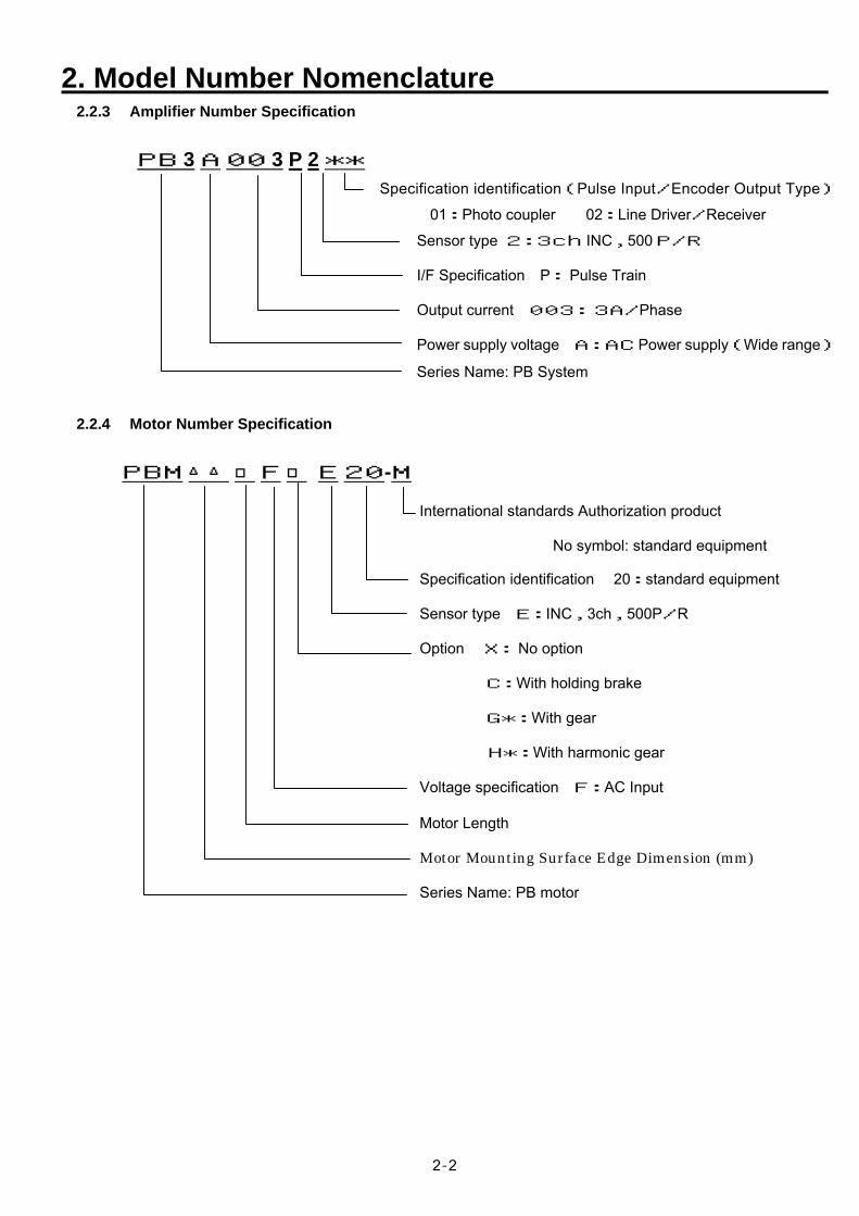
2.2.3 Amplifier Number Specification
PB 3 A 00 3 P 2 ** Specification identification(Pulse Input/Encoder Output Type)
01:Photo coupler 02:Line Driver/Receiver
Sensor type 2:3ch INC,500P/R
I/F Specification P: Pulse Train
Output current 003: 3A/Phase
Power supply voltage A:AC Power supply(Wide range)
Series Name: PB System 2.2.4 Motor Number Specification PBM F E 20-M
International standards Authorization product
No symbol: standard equipment
Specification identification 20:standard equipment
Sensor type E:INC,3ch,500P/R
Option X: No option
C:With holding brake
G*:With gear
H*:With harmonic gear
Voltage specification F:AC Input
Motor Length
Motor Mounting Surface Edge Dimension (mm)
Series Name: PB motor
2. Model Number Nomenclature
2-3
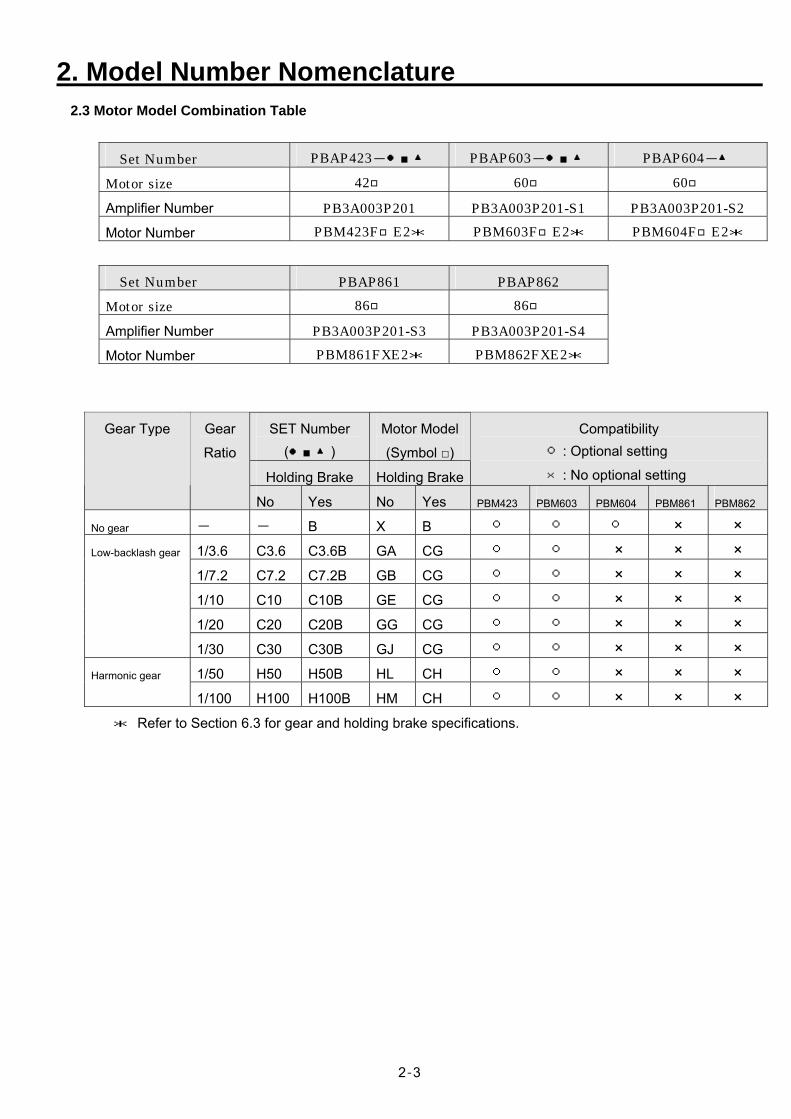
2.3 Motor Model Combination Table
Set Number PBAP423- PBAP603- PBAP604-
Motor size 42 60 60
Amplifier Number PB3A003P201 PB3A003P201-S1 PB3A003P201-S2 Motor Number PBM423FE2* PBM603FE2* PBM604FE2*
Set Number PBAP861 PBAP862 Motor size 86 86
Amplifier Number PB3A003P201-S3 PB3A003P201-S4 Motor Number PBM861FXE2* PBM862FXE2*
SET Number ()
Motor Model
(Symbol )
Holding Brake Holding Brake
Compatibility : Optional setting
×: No optional setting
Gear Type Gear
Ratio
No Yes No Yes PBM423 PBM603 PBM604 PBM861 PBM862
No gear - - B X B × × 1/3.6 C3.6 C3.6B GA CG × × × 1/7.2 C7.2 C7.2B GB CG × × × 1/10 C10 C10B GE CG × × × 1/20 C20 C20B GG CG × × ×
Low-backlash gear
1/30 C30 C30B GJ CG × × × 1/50 H50 H50B HL CH × × × Harmonic gear
1/100 H100 H100B HM CH × × × * Refer to Section 6.3 for gear and holding brake specifications.
3. Installation, Wiring and Operation
3-1
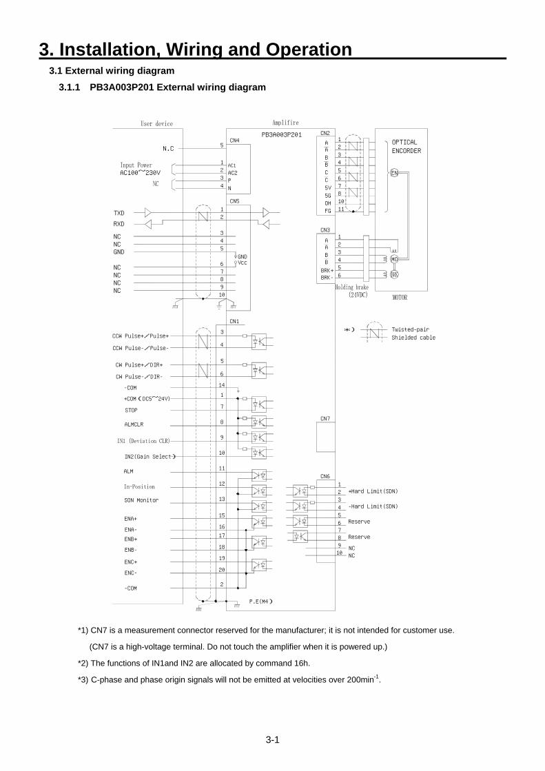
3.1 External wiring diagram 3.1.1 PB3A003P201 External wiring diagram
CW Pulse+/DIR+
ENA+
-COM
ENC-
ENC+
ENB+
ENB-
ENA-
P.E(M4)
19
2
20
17
18
16
ALMCLR
STOP
CW Pulse-/DIR-
+COM(DC5~24V)
-COM
12
13
15
11
10
7
8
9
14
1
6
NC
8
NC910
76
345
21
CN6
CN7
TXD1
NC
CCW Pulse+/Pulse+
CCW Pulse-/Pulse-
GND
NCNCNC
NCNC
RXD
9
CN1
4
5
3
10
GNDVcc
5
78
6
34
2
N.C
PB3ACN4
CN5
003P201
2 AC23
4PN
1AC1
5
11FG
*)
A3
BRK+BRK-
BB
56
4
CN3
A21
MO
CN2
5C
OH5G
C5V
810
76
BB
AA
34
21
EN
ENCORDEROPTICAL
ALM
AC100~230V
IN2(Gain Select)
SON Monitor
+Hard Limit(SDN)
-Hard Limit(SDN)
Reserve
Reserve
Twisted-pair
Shielded cable
*1) CN7 is a measurement connector reserved for the manufacturer; it is not intended for customer use.
(CN7 is a high-voltage terminal. Do not touch the amplifier when it is powered up.)
*2) The functions of IN1and IN2 are allocated by command 16h.
*3) C-phase and phase origin signals will not be emitted at velocities over 200min-1.
3. Installation, Wiring and Operation
3-2
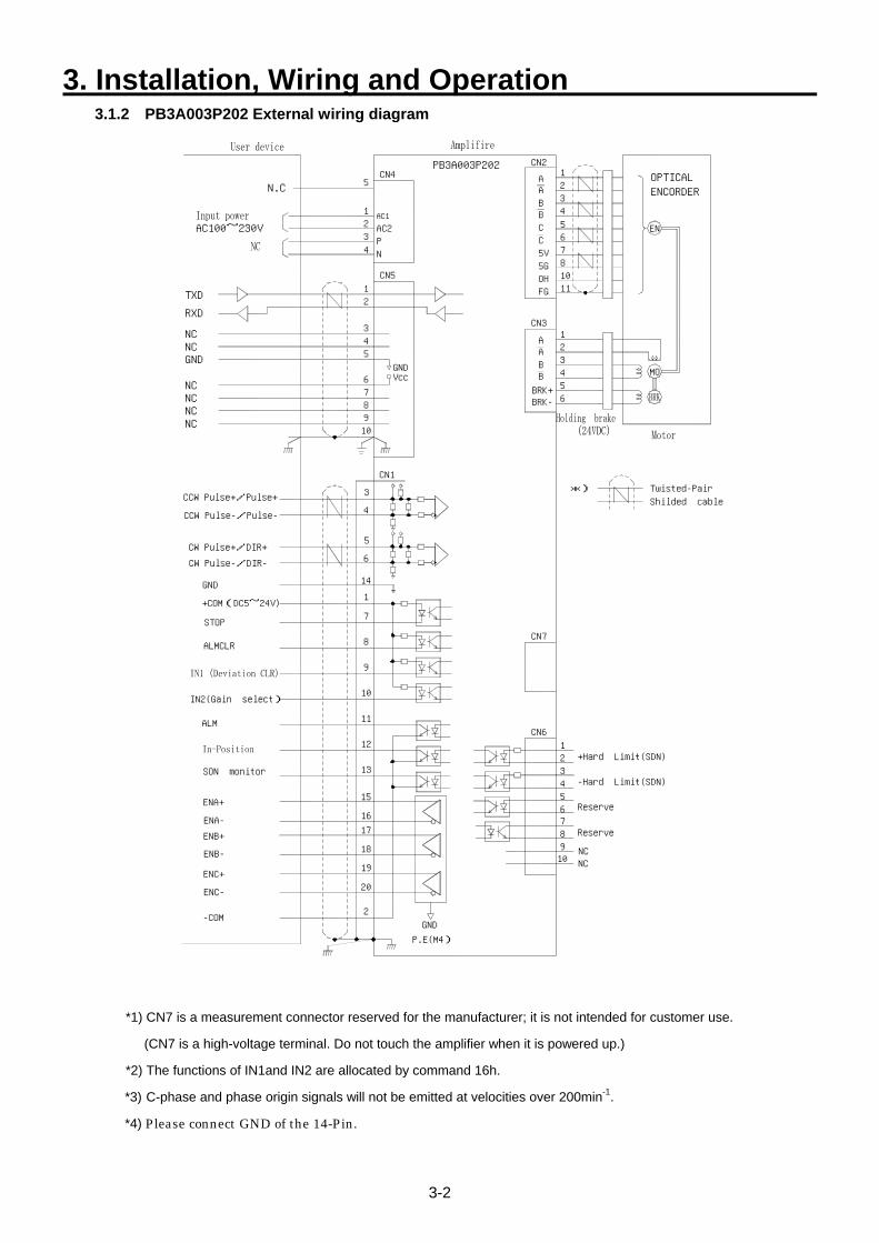
3.1.2 PB3A003P202 External wiring diagram
CW Pulse+/DIR+
ENA+
-COM
ENC-
ENC+
ENB+
ENB-
ENA-
P.E(M4)
19
2
20
17
18
16
ALMCLR
STOP
CW Pulse-/DIR-
+COM(DC5~24V)
GND
12
13
15
11
10
7
8
9
14
1
6
NC
8
NC910
76
345
21
CN6
CN7
TXD1
NC
CCW Pulse-/Pulse-
CCW Pulse+/Pulse+
GND
NCNCNC
NCNC
RXD
9
CN1
5
3
4
10
GNDVcc
5
78
6
34
2
AC100~230V
N.C
PB3A003P202CN4
CN5
2 AC23
4PN
1AC1
5
11FG
*)
A3
BRK+BRK-
BB
56
4
CN3
A21
MO
CN2
5C
OH5G
C5V
810
76
BB
AA
34
21
EN
ENCORDEROPTICAL
GND
ALM
IN2(Gain select)
SON monitor
Twisted-Pair
Shilded cable
+Hard Limit(SDN)
-Hard Limit(SDN)
Reserve
Reserve
*1) CN7 is a measurement connector reserved for the manufacturer; it is not intended for customer use.
(CN7 is a high-voltage terminal. Do not touch the amplifier when it is powered up.)
*2) The functions of IN1and IN2 are allocated by command 16h.
*3) C-phase and phase origin signals will not be emitted at velocities over 200min-1. *4) Please connect GND of the 14-Pin.
3. Installation, Wiring and Operation
3-3
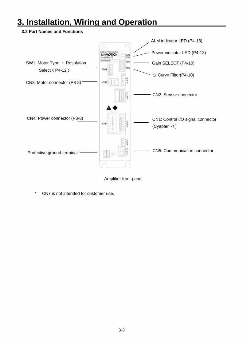
3.2 Part Names and Functions
Amplifier front panel
ALM indicator LED (P4-13)
Power indicator LED (P4-13)
S Curve Filter(P4-10)
CN1: Control I/O signal connector (Cyapter 4)
CN2: Sensor connector
CN3: Motor connector (P3-8)
SW1: Motor Type 、Resolution
Select(P4-12)
CN5: Communication connector
CN4: Power connector (P3-8)
Protective ground terminal
Gain SELECT (P4-10) SW1
CN4
CN3N
N
N
N
C
C
C
C
7
1
2
5
NC
6
* CN7 is not intended for customer use.
3. Installation, Wiring and Operation
3-4
3.3 Installation 3.3.1 Amplifier Installation Precautions ・ The amplifier must be installed in an enclosure. Carefully consider the size of the case, the cooling
method, and the location so that the ambient temperature around the amplifier does not exceed 55°C.For longevity and high reliability, it is recommended to keep the temperature around the amplifier below 40°C.
・ The amplifier has an internal overheating detection function. Consider the cooling method to be used if an amplifier overheating error is detected.
・ If there is a vibration source nearby, use a shock absorber between the amplifier and the installation base to prevent the vibration from directly affecting the amplifier.
・ Long-term use in the presence of corrosive gas may cause contact failure on the connectors and on connecting parts. Never use the device where it may be subjected to corrosive gas.
・ Do not use the device where explosive or combustible gas is present, as this could cause fire or an explosion.
・ Do not use the device where dust or oil mist is present. If dust or oil mist attaches to and accumulates on the device, it can cause insulation deterioration or leakage between the conductive parts, and damage the amplifier.
・ A large noise source may cause inductive noise to enter the input signals or the power circuit, and can cause a malfunction. If there is a possibility of noise, insert a noise filter, inspect the line wiring and take appropriate noise prevention measures.
3.3.2 Amplifier Installation Method 1) Installation dimensions
The amplifier must be installed using two M4 screws on its rear panel. Refer to the amplifier outline
drawing (Section 6.5) for the installation dimensions.
2) Installation direction
The amplifier uses natural convection cooling. The installation direction must be vertical. Do not install
the unit upside down.
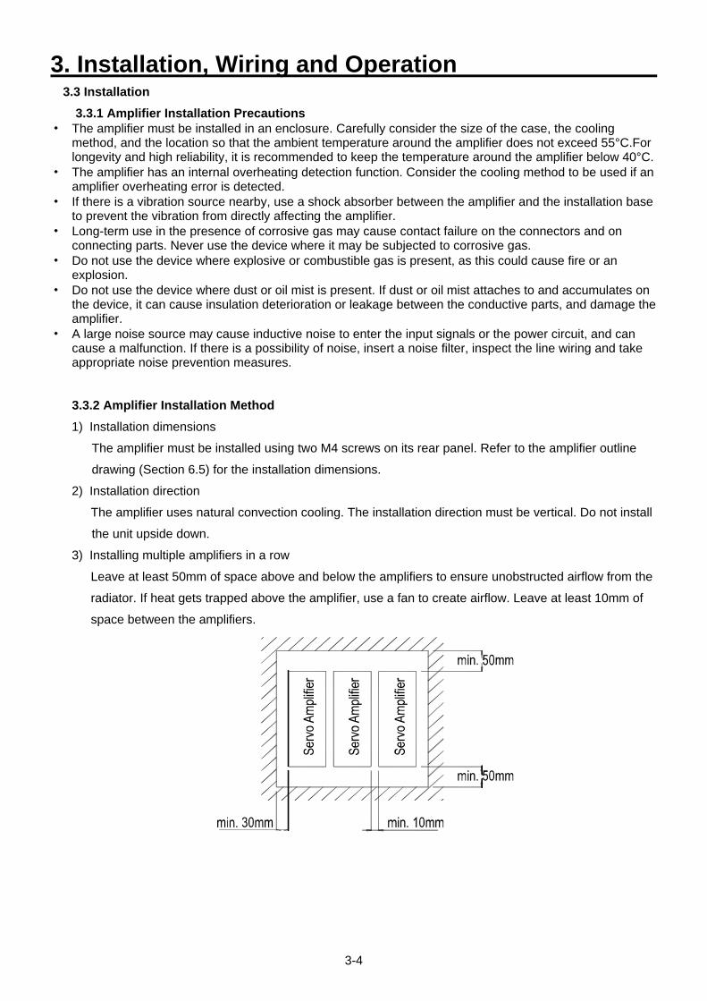
3) Installing multiple amplifiers in a row
Leave at least 50mm of space above and below the amplifiers to ensure unobstructed airflow from the
radiator. If heat gets trapped above the amplifier, use a fan to create airflow. Leave at least 10mm of
space between the amplifiers.
3. Installation, Wiring and Operation
3-5
3.3.3 Motor Installation Precautions ・ If the motor is enclosed in an enclosure, consider its size, the use of a heat sink, and ensure the
temperature inside the case is between 0 and 40°C.
・ Consider a radiation method to ensure that the surface temperature of the motor (end cap surface
temperature) does not exceed 85°C. (If the motor overheating prevention function is working, an ALM will
be detected.)
・ When installing a pulley or a gear to the motor, avoid methods such as press fitting that apply force in the
torque direction. Ensure accurate shaft centering when integrating the rotating shaft of the motor with the
target machinery. Incorrect centering can damage the shaft and the bearings.
・ Avoid installation in places where the unit may be subjected to water, cutting fluid, rain or conductive
particles such as dust and iron filings.
・ Never install the unit where it could be subjected to corrosive (acid, alkali, etc.), flammable, explosive liquids or
fumes.
・ Avoid installing the motor on moving parts. Since the wires and cables used for this device are electric
connection wires, disconnection could occur. Contact the manufacturer for assistance for use on moving parts.
・ If a belt-drive is used, verify that the gear reduction value of the belt tension does not exceed the thrust
load tolerance. Refer to 6.2 and 6.3)
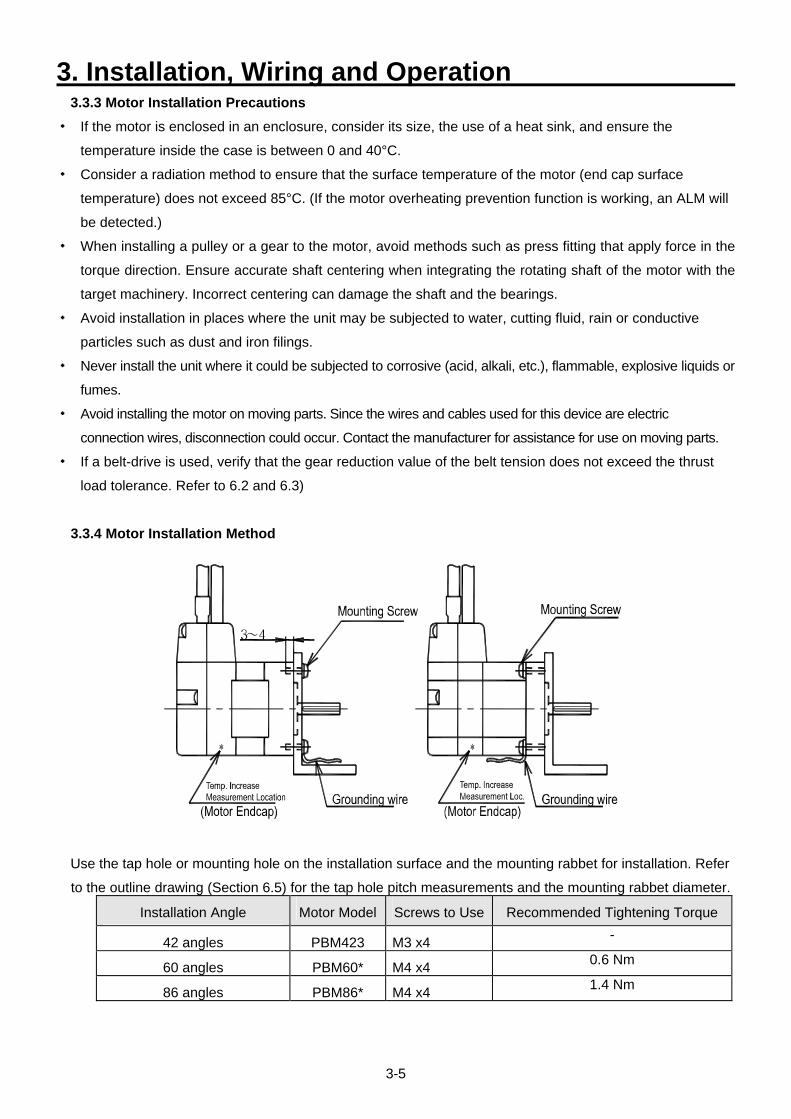
3.3.4 Motor Installation Method
Use the tap hole or mounting hole on the installation surface and the mounting rabbet for installation. Refer
to the outline drawing (Section 6.5) for the tap hole pitch measurements and the mounting rabbet diameter.
Installation Angle Motor Model Screws to Use Recommended Tightening Torque
42 angles PBM423 M3 x4 -
60 angles PBM60* M4 x4 0.6 Nm
86 angles PBM86* M4 x4 1.4 Nm
3. Installation, Wiring and Operation
3-6
3.4 Wiring 3.4.1 Wiring Precautions
1) Noise protection
Follow the instructions below to prevent malfunctions due to noise.
・ The noise filter, amplifier and the host controller should be placed at the minimum distance.
・ Apply a surge absorber circuit to coils such as relays, electromagnetic contacts, induction
motors and brake solenoids, etc.
・ Do not enclose the power lines, the motor lines, and the signal lines in the same wire
conduit; they are not intended to be bundled together.
・ If there are large noise sources such as electric welding machines or electric discharge
machines nearby, apply a noise filter for the power line and the input circuit.
・ Do not bundle the primary and secondary wiring of the noise filter together.
2) Wiring
Perform wiring only when power is cut off. Carefully verify that wiring is correct, as faulty wiring
can cause damage to the device.
3) Cables for wiring
Use the correct size of cables as specified for wiring. (Refer to Section 3.4.3)
4) Emergency stop circuit
Be sure to install an external emergency stop circuit that can stop the device and cut off the power
instantaneously.
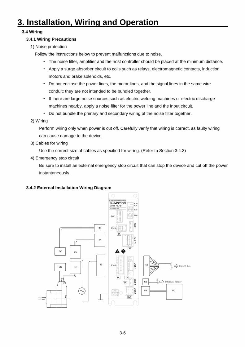
3.4.2 External Installation Wiring Diagram
3D 2D
N5
4B CN4
N
C
6
C
N1
C
3C 2C
C
2B
3B CN3
N2
C
N7
SW1
5B PC
6B
1B
3. Installation, Wiring and Operation
3-7
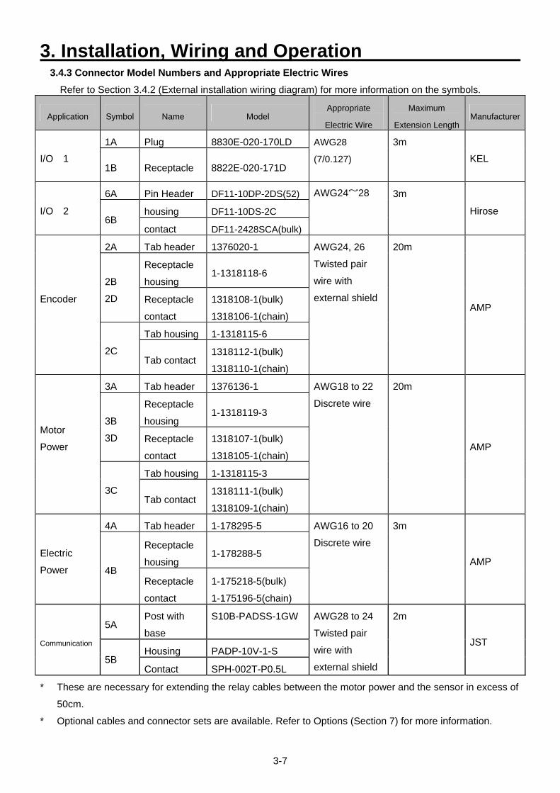
3.4.3 Connector Model Numbers and Appropriate Electric Wires Refer to Section 3.4.2 (External installation wiring diagram) for more information on the symbols.
Application Symbol Name Model Appropriate
Electric Wire
Maximum
Extension Length Manufacturer
1A Plug 8830E-020-170LD
I/O 1 1B Receptacle 8822E-020-171D
AWG28
(7/0.127)
3m
KEL
6A Pin Header DF11-10DP-2DS(52)
housing DF11-10DS-2C I/O 2 6B
contact DF11-2428SCA(bulk)
AWG24~28 3m
Hirose
2A Tab header 1376020-1
Receptacle
housing 1-1318118-6
2B
2D Receptacle
contact
1318108-1(bulk)
1318106-1(chain)
Tab housing 1-1318115-6
Encoder
2C Tab contact
1318112-1(bulk)
1318110-1(chain)
AWG24, 26
Twisted pair
wire with
external shield
20m
AMP
3A Tab header 1376136-1
Receptacle
housing 1-1318119-3
3B
3D Receptacle
contact
1318107-1(bulk)
1318105-1(chain)
Tab housing 1-1318115-3
Motor
Power
3C Tab contact
1318111-1(bulk)
1318109-1(chain)
AWG18 to 22
Discrete wire
20m
AMP
4A Tab header 1-178295-5
Receptacle
housing 1-178288-5 Electric
Power 4B Receptacle
contact
1-175218-5(bulk)
1-175196-5(chain)
AWG16 to 20
Discrete wire
3m
AMP
5A Post with
base
S10B-PADSS-1GW
Housing PADP-10V-1-S Communication
5B Contact SPH-002T-P0.5L
AWG28 to 24
Twisted pair
wire with
external shield
2m
JST
* These are necessary for extending the relay cables between the motor power and the sensor in excess of
50cm.
* Optional cables and connector sets are available. Refer to Options (Section 7) for more information.
3. Installation, Wiring and Operation
3-8
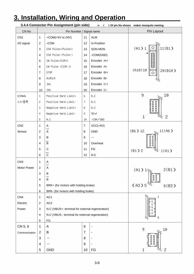
3.4.4 Connector Pin Assignment (pin side) * ( )Of pin No shows maker mosquito naming.
CN No Pin Number / Signal name Pin Layout
CN1
I/O signal
1
2
3
4
5
6
7
8
9
10
+COM(+5V to 24V)
-COM
CCW Pulse+(Pulse+)
CCW Pulse-(Pulse-)
CW Pulse+(DIR+)
CW Pulse-(DIR-)
STOP
ALMCLR
IN1
IN2
11
12
13
14
15
16
17
18
19
20
ALM
In-Position
SON MON
-COM(GND)
Encoder A+
Encoder A-
Encoder B+
Encoder B-
Encoder C+
Encoder C-
(A1)1
(A10)10
11(B1)
20(B10)
CN6
I/O 信号
1
2
3
4
5
Positive Hard Limit+
Positive Hard Limit-
Negative Hard Limit+
Negative Hard Limit-
N.C
6
7
8
9
10
N.C
N.C
N.C
5V
-COM/GND 1 2
9 10
CN2
Sensor
1
2
3
4
5
6
A
A
B
B
C
C
7
8
9
10
11
12
VCC(+5V)
GND
-
Overheat
FG
N.C
1(A1)
11(A6)
(B1)2
(B6)12
CN3
Motor Power
1
2
3
4
5
6
A
A
B
B
BRK+ (for motors with holding brake)
BRK- (for motors with holding brake)
(A1)1
(A3)5
2(B1)
6(B3)
CN4
Electric
Power
1
2
3
4
5
AC1
AC2
N.C (VBUS+: terminal for external regeneration)
N.C (VBUS-: terminal for external regeneration)
FG 5
1
CN 5, 6
Communication
1
2
3
4
5
A
B -
-
GND
6
7
8
9
10
-
-
-
-
FG 1 2
9 10
3. Installation, Wiring and Operation
3-9
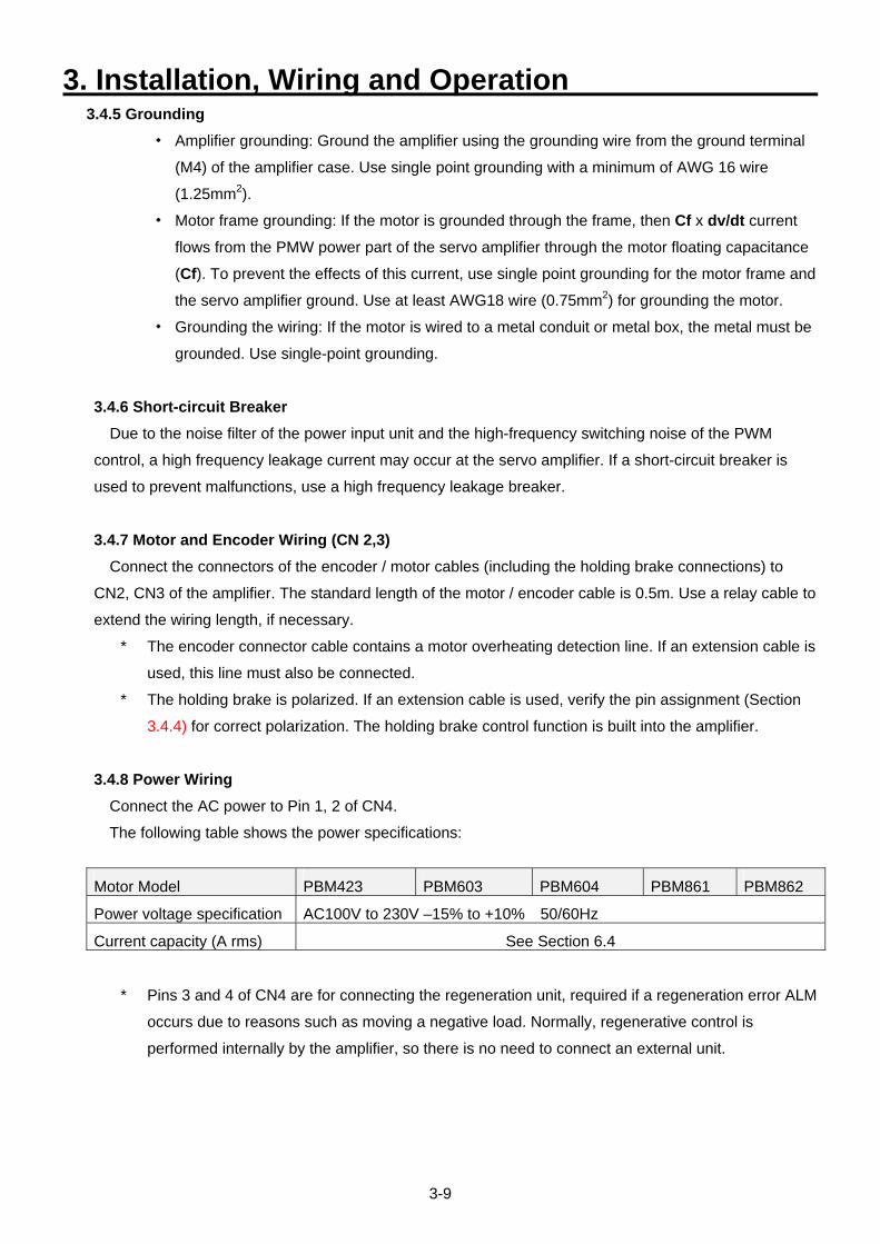
3.4.5 Grounding ・ Amplifier grounding: Ground the amplifier using the grounding wire from the ground terminal
(M4) of the amplifier case. Use single point grounding with a minimum of AWG 16 wire
(1.25mm2).
・ Motor frame grounding: If the motor is grounded through the frame, then Cf x dv/dt current
flows from the PMW power part of the servo amplifier through the motor floating capacitance
(Cf). To prevent the effects of this current, use single point grounding for the motor frame and
the servo amplifier ground. Use at least AWG18 wire (0.75mm2) for grounding the motor.
・ Grounding the wiring: If the motor is wired to a metal conduit or metal box, the metal must be
grounded. Use single-point grounding.
3.4.6 Short-circuit Breaker Due to the noise filter of the power input unit and the high-frequency switching noise of the PWM
control, a high frequency leakage current may occur at the servo amplifier. If a short-circuit breaker is
used to prevent malfunctions, use a high frequency leakage breaker.
3.4.7 Motor and Encoder Wiring (CN 2,3) Connect the connectors of the encoder / motor cables (including the holding brake connections) to
CN2, CN3 of the amplifier. The standard length of the motor / encoder cable is 0.5m. Use a relay cable to
extend the wiring length, if necessary.
* The encoder connector cable contains a motor overheating detection line. If an extension cable is
used, this line must also be connected.
* The holding brake is polarized. If an extension cable is used, verify the pin assignment (Section
3.4.4) for correct polarization. The holding brake control function is built into the amplifier.
3.4.8 Power Wiring Connect the AC power to Pin 1, 2 of CN4.
The following table shows the power specifications:
Motor Model PBM423 PBM603 PBM604 PBM861 PBM862
Power voltage specification AC100V to 230V –15% to +10% 50/60Hz
Current capacity (A rms) See Section 6.4
* Pins 3 and 4 of CN4 are for connecting the regeneration unit, required if a regeneration error ALM
occurs due to reasons such as moving a negative load. Normally, regenerative control is
performed internally by the amplifier, so there is no need to connect an external unit.
4. Input / Output Signal Functions
4-1
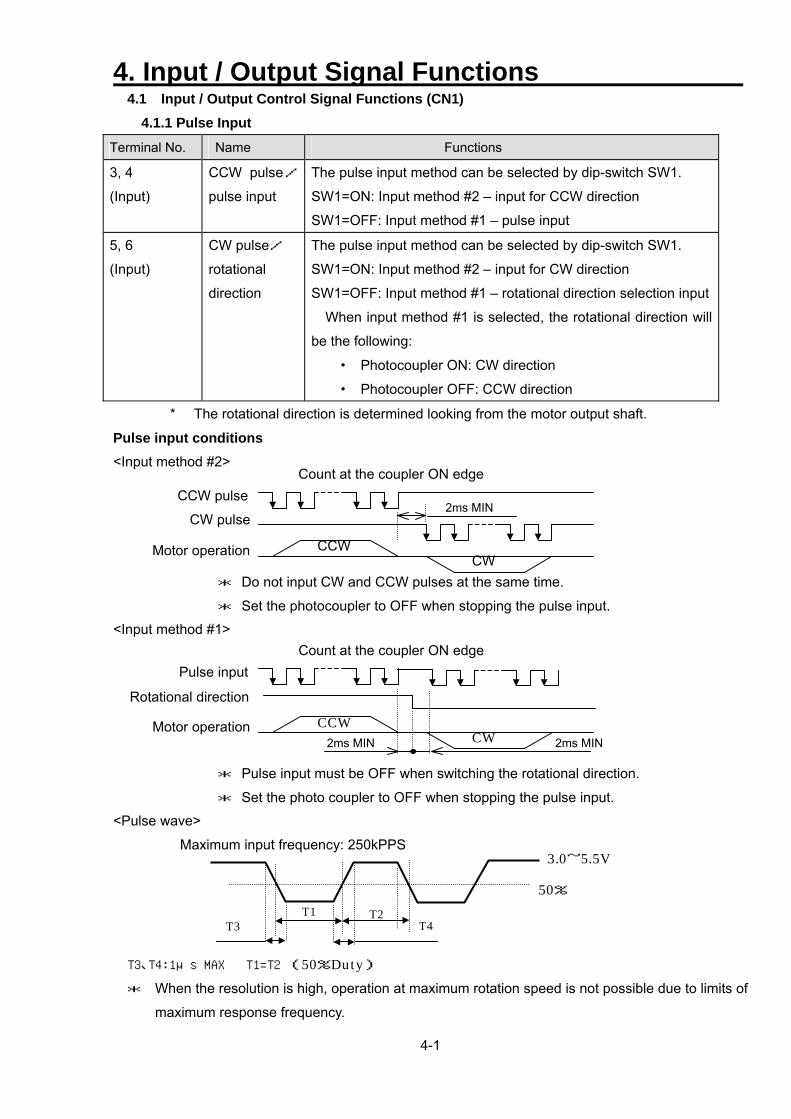
4.1 Input / Output Control Signal Functions (CN1) 4.1.1 Pulse Input
Terminal No. Name Functions
3, 4
(Input)
CCW pulse/
pulse input
The pulse input method can be selected by dip-switch SW1.
SW1=ON: Input method #2 – input for CCW direction
SW1=OFF: Input method #1 – pulse input
5, 6
(Input)
CW pulse/
rotational
direction
The pulse input method can be selected by dip-switch SW1.
SW1=ON: Input method #2 – input for CW direction
SW1=OFF: Input method #1 – rotational direction selection input
When input method #1 is selected, the rotational direction will
be the following:
・ Photocoupler ON: CW direction
・ Photocoupler OFF: CCW direction
* The rotational direction is determined looking from the motor output shaft.
Pulse input conditions <Input method #2>
Count at the coupler ON edge
CCW pulse2ms MIN
CW CCW
CW pulse
Motor operation
* Do not input CW and CCW pulses at the same time.
* Set the photocoupler to OFF when stopping the pulse input.
<Input method #1> Count at the coupler ON edge
Pulse input
CCW CW 2ms MIN 2ms MIN
Rotational direction
Motor operation
* Pulse input must be OFF when switching the rotational direction.
* Set the photo coupler to OFF when stopping the pulse input.
<Pulse wave>
Maximum input frequency: 250kPPS
T3 T4 T2 T1
50%
3.0~5.5V
T3、T4:1μs MAX T1=T2 (50%Duty) * When the resolution is high, operation at maximum rotation speed is not possible due to limits of
maximum response frequency.
4. Input / Output Signal Functions
4-2
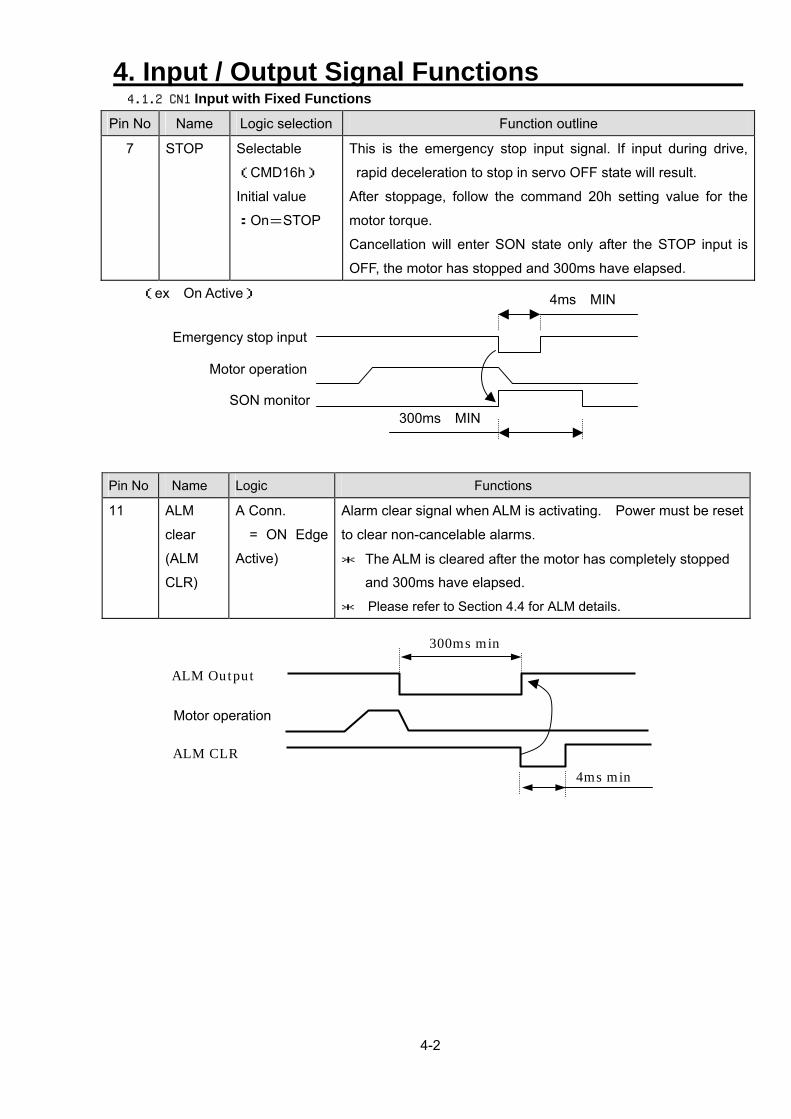
4.1.2 CN1 Input with Fixed Functions
Pin No Name Logic selection Function outline
7 STOP Selectable
(CMD16h)
Initial value
:On=STOP
This is the emergency stop input signal. If input during drive,
rapid deceleration to stop in servo OFF state will result.
After stoppage, follow the command 20h setting value for the
motor torque.
Cancellation will enter SON state only after the STOP input is
OFF, the motor has stopped and 300ms have elapsed.
(ex On Active) 4ms MIN
Eme
300ms MINSON monitor
Motor operation
rgency stop input
Pin No Name Logic Functions
11
ALM
clear
(ALM
CLR)
A Conn.
= ON Edge
Active)
Alarm clear signal when ALM is activating. Power must be reset
to clear non-cancelable alarms.
* The ALM is cleared after the motor has completely stopped
and 300ms have elapsed.
* Please refer to Section 4.4 for ALM details.
4ms min
300ms min
ALM Output
Motor operation
ALM CLR
4. Input / Output Signal Functions
4-3
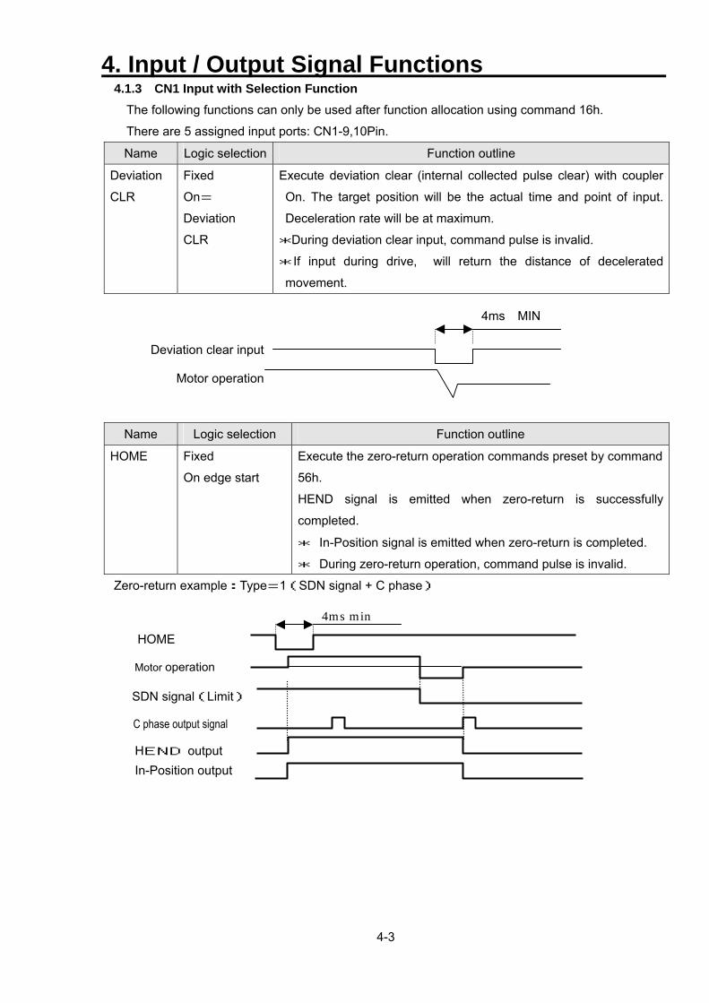
4.1.3 CN1 Input with Selection Function The following functions can only be used after function allocation using command 16h.
There are 5 assigned input ports: CN1-9,10Pin.
Name Logic selection Function outline
Deviation
CLR
Fixed
On=
Deviation
CLR
Execute deviation clear (internal collected pulse clear) with coupler
On. The target position will be the actual time and point of input.
Deceleration rate will be at maximum.
*During deviation clear input, command pulse is invalid.
* If input during drive, will return the distance of decelerated
movement.
4ms MIN
Deviation clear input
Name Logic selection Function outline
HOME Fixed
On edge start
Execute the zero-return operation commands preset by command
56h.
HEND signal is emitted when zero-return is successfully
completed.
* In-Position signal is emitted when zero-return is completed.
* During zero-return operation, command pulse is invalid.
Zero-return example:Type=1(SDN signal + C phase)
Motor operation
Motor operation
SDN signal(Limit)
C phase output signal
HEND output In-Position output
HOME
4ms min
4. Input / Output Signal Functions
4-4
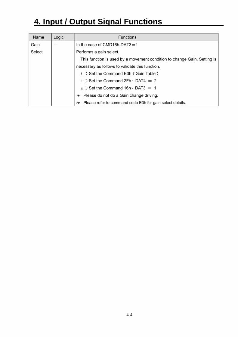
Name Logic Functions
Gain
Select
-
In the case of CMD16h-DAT3=1
Performs a gain select.
This function is used by a movement condition to change Gain. Setting is
necessary as follows to validate this function.
ⅰ)Set the Command E3h(Gain Table)
ⅱ)Set the Command 2Fh、DAT4 = 2
ⅲ)Set the Command 16h、DAT3 = 1
* Please do not do a Gain change driving.
* Please refer to command code E3h for gain select details.
4. Input / Output Signal Functions
4-5
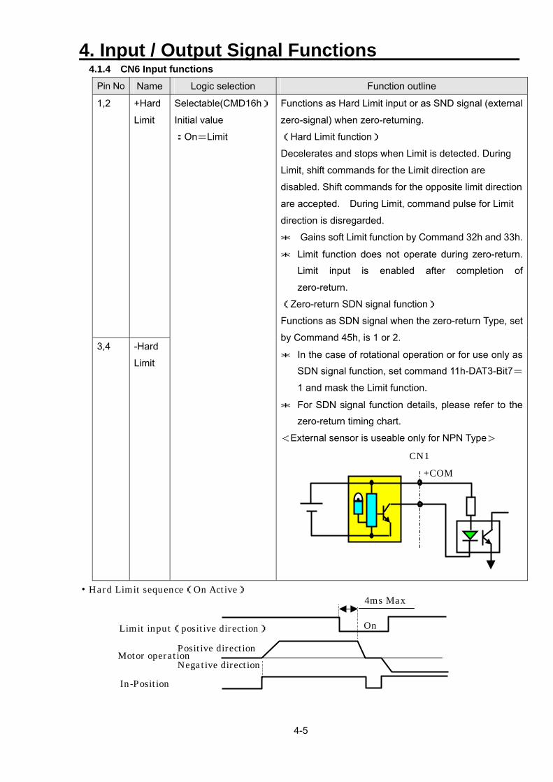
4.1.4 CN6 Input functions Pin No Name Logic selection Function outline
1,2 +Hard
Limit
3,4 -Hard
Limit
Selectable(CMD16h)
Initial value
:On=Limit
Functions as Hard Limit input or as SND signal (external
zero-signal) when zero-returning.
(Hard Limit function)
Decelerates and stops when Limit is detected. During
Limit, shift commands for the Limit direction are
disabled. Shift commands for the opposite limit direction
are accepted. During Limit, command pulse for Limit
direction is disregarded.
* Gains soft Limit function by Command 32h and 33h.
* Limit function does not operate during zero-return.
Limit input is enabled after completion of
zero-return.
(Zero-return SDN signal function)
Functions as SDN signal when the zero-return Type, set
by Command 45h, is 1 or 2.
* In the case of rotational operation or for use only as
SDN signal function, set command 11h-DAT3-Bit7=
1 and mask the Limit function.
* For SDN signal function details, please refer to the
zero-return timing chart.
<External sensor is useable only for NPN Type>
CN1 +COM
・Hard Limit sequence(On Active)
Limit input(positive direction)
Motor operation Positive direction Negative direction
On
4ms Max
In-Position
4. Input / Output Signal Functions
4-6
4.1.5 CN1 Output Signal with Fixed Functions Note)When the power is turned on, the status of each output Port is uncertain until the CPU is in
motion. Observe output Ports for more than 5 seconds after the power supply voltage has
settled.
Pin No Name Logic selection Function outline
11 ALM Selectable
(CMD16h)
Initial value
On=ALM
Issued when alarm is activated
* Detects low voltage error when power failure occurs
with the servo ON. Switch off the power with the servo
OFF if the alarm becomes a problem.
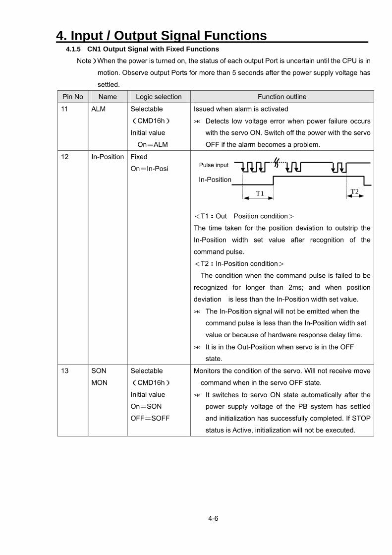
12 In-Position Fixed
On=In-Posi
<T1:Out Position condition>
The time taken for the position deviation to outstrip the
In-Position width set value after recognition of the
command pulse.
<T2:In-Position condition>
The condition when the command pulse is failed to be
recognized for longer than 2ms; and when position
deviation is less than the In-Position width set value.
* The In-Position signal will not be emitted when the
command pulse is less than the In-Position width set
value or because of hardware response delay time.
* It is in the Out-Position when servo is in the OFF
state.
13 SON
MON
Selectable
(CMD16h)
Initial value
On=SON
OFF=SOFF
Monitors the condition of the servo. Will not receive move
command when in the servo OFF state.
* It switches to servo ON state automatically after the
power supply voltage of the PB system has settled
and initialization has successfully completed. If STOP
status is Active, initialization will not be executed.
Pulse input
In-Position
T2 T1
4. Input / Output Signal Functions
4-7
Pin No Name Logic selection Function outline
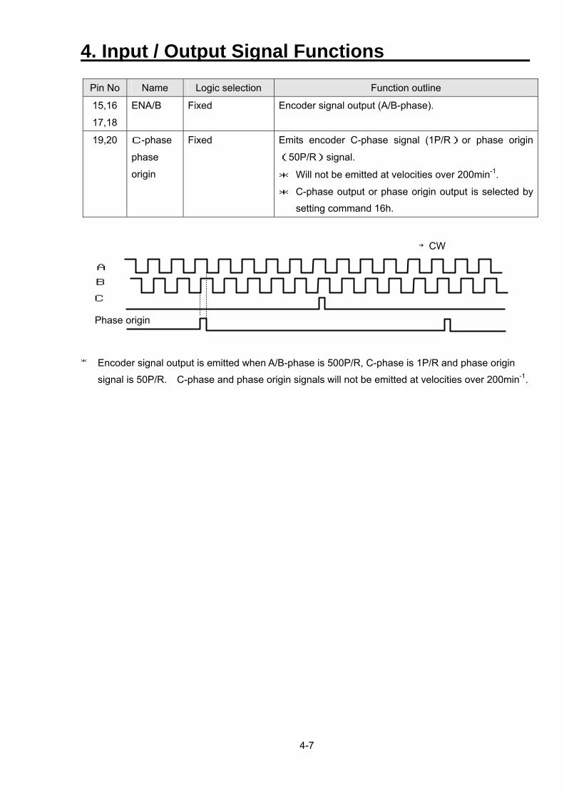
15,16
17,18
ENA/B Fixed Encoder signal output (A/B-phase).
19,20 C-phase
phase
origin
Fixed Emits encoder C-phase signal (1P/R)or phase origin
(50P/R)signal.
* Will not be emitted at velocities over 200min-1.
* C-phase output or phase origin output is selected by
setting command 16h.
A
B C
Phase origin
→CW * Encoder signal output is emitted when A/B-phase is 500P/R, C-phase is 1P/R and phase origin
signal is 50P/R. C-phase and phase origin signals will not be emitted at velocities over 200min-1.
4. Input / Output Signal Functions
4-8
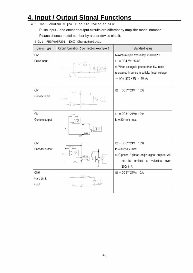
4.2 Input/Output Signal Electric Characteristic
Pulse input、and encoder output circuits are different by amplifier model number.
Please choose model number by a user device circuit.
4.2.1 PB3A003P201 DC Characteristic
Circuit Type Circuit formation(connection example) Standard value
CN1
Pulse input
Maximum input frequency: 250000PPS
E=DC4.5V~5.5V
*When voltage is greater than 5V, insert
resistance in series to satisfy; (input voltage
-1V) / (270 + R) ≒10mA
CN1
Generic input
E=DC5~24V±10%
CN1
Generic output
Ic
11~13
2,14
-COM
E
E=DC5~24V±10%
Ic=30mA max
CN1
Encoder output Ic
E
-COM
E=DC5~24V±10%
Ic=30mA max
*C-phase / phase origin signal outputs will
not be emitted at velocities over
200min-1.
CN6
Hard Limit
input
E=DC5~24V±10%
4. Input / Output Signal Functions
4-9
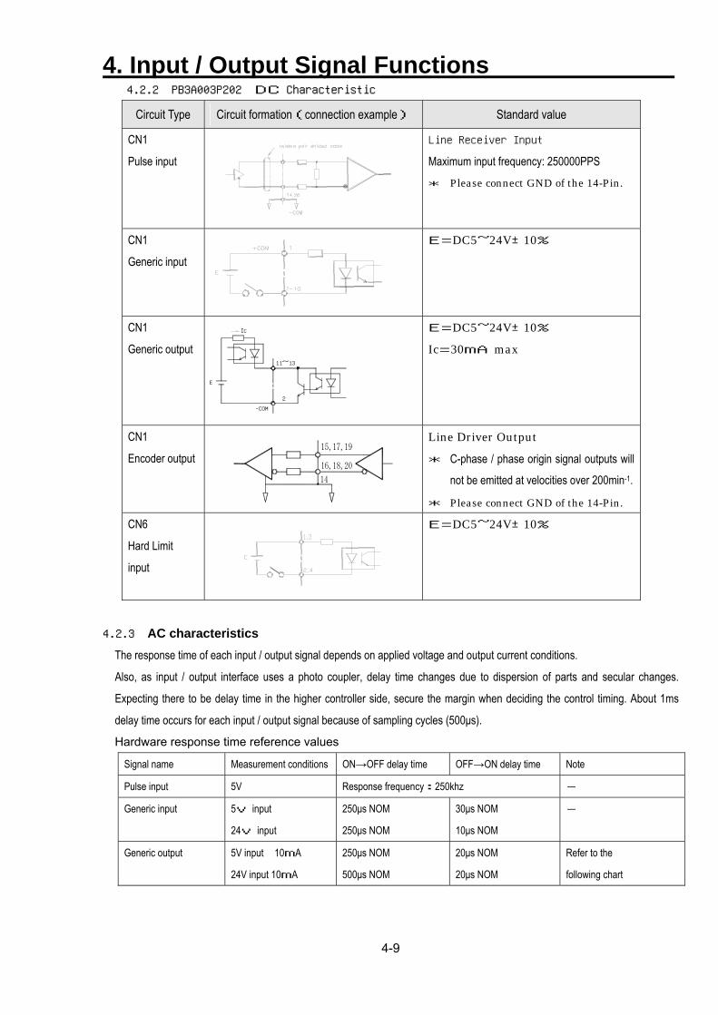
4.2.2 PB3A003P202 DC Characteristic
Circuit Type Circuit formation(connection example) Standard value
CN1
Pulse input
Line Receiver Input
Maximum input frequency: 250000PPS
* Please connect GND of the 14-Pin.
CN1
Generic input
E=DC5~24V±10%
CN1
Generic output
E
-COM
11~13
Ic
2
E=DC5~24V±10%
Ic=30mA max
CN1
Encoder output
Line Driver Output
* C-phase / phase origin signal outputs will
not be emitted at velocities over 200min-1.
* Please connect GND of the 14-Pin.
CN6
Hard Limit
input
E=DC5~24V±10%
4.2.3 AC characteristics
The response time of each input / output signal depends on applied voltage and output current conditions.
Also, as input / output interface uses a photo coupler, delay time changes due to dispersion of parts and secular changes.
Expecting there to be delay time in the higher controller side, secure the margin when deciding the control timing. About 1ms
delay time occurs for each input / output signal because of sampling cycles (500µs).
Hardware response time reference values
Signal name Measurement conditions ON→OFF delay time OFF→ON delay time Note
Pulse input 5V Response frequency:250khz -
Generic input 5v input
24v input
250µs NOM
250µs NOM
30µs NOM
10µs NOM
-
Generic output 5V input 10mA
24V input 10mA
250µs NOM
500µs NOM
20µs NOM
20µs NOM
Refer to the
following chart
4. Input / Output Signal Functions
4-10
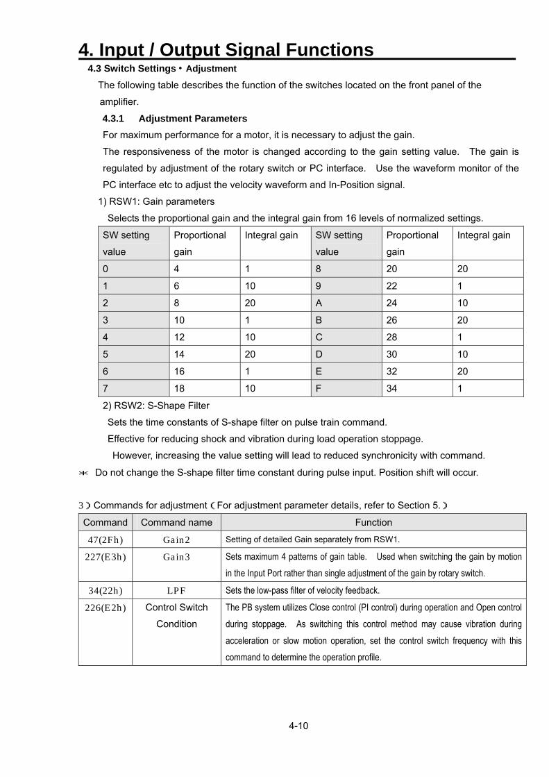
4.3 Switch Settings・Adjustment The following table describes the function of the switches located on the front panel of the
amplifier.
4.3.1 Adjustment Parameters For maximum performance for a motor, it is necessary to adjust the gain.
The responsiveness of the motor is changed according to the gain setting value. The gain is
regulated by adjustment of the rotary switch or PC interface. Use the waveform monitor of the
PC interface etc to adjust the velocity waveform and In-Position signal.
1) RSW1: Gain parameters
Selects the proportional gain and the integral gain from 16 levels of normalized settings.
SW setting
value
Proportional
gain
Integral gain SW setting
value
Proportional
gain
Integral gain
0 4 1 8 20 20
1 6 10 9 22 1
2 8 20 A 24 10
3 10 1 B 26 20
4 12 10 C 28 1
5 14 20 D 30 10
6 16 1 E 32 20
7 18 10 F 34 1
2) RSW2: S-Shape Filter
Sets the time constants of S-shape filter on pulse train command.
Effective for reducing shock and vibration during load operation stoppage.
However, increasing the value setting will lead to reduced synchronicity with command.
* Do not change the S-shape filter time constant during pulse input. Position shift will occur.
3)Commands for adjustment(For adjustment parameter details, refer to Section 5.)
Command Command name Function
47(2Fh) Gain2 Setting of detailed Gain separately from RSW1.
227(E3h) Gain3 Sets maximum 4 patterns of gain table. Used when switching the gain by motion in the Input Port rather than single adjustment of the gain by rotary switch.
34(22h) LPF Sets the low-pass filter of velocity feedback. 226(E2h) Control Switch
Condition
The PB system utilizes Close control (PI control) during operation and Open control during stoppage. As switching this control method may cause vibration during acceleration or slow motion operation, set the control switch frequency with this command to determine the operation profile.
4. Input / Output Signal Functions
4-11
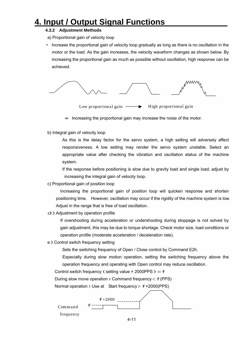
4.3.2 Adjustment Methods a) Proportional gain of velocity loop
・ Increase the proportional gain of velocity loop gradually as long as there is no oscillation in the
motor or the load. As the gain increases, the velocity waveform changes as shown below. By
increasing the proportional gain as much as possible without oscillation, high response can be
achieved.
High proportional gain Low proportional gain
* Increasing the proportional gain may increase the noise of the motor.
b) Integral gain of velocity loop
As this is the delay factor for the servo system, a high setting will adversely affect
responsiveness. A low setting may render the servo system unstable. Select an
appropriate value after checking the vibration and oscillation status of the machine
system.
If the response before positioning is slow due to gravity load and single load, adjust by
increasing the integral gain of velocity loop.
c) Proportional gain of position loop
Increasing the proportional gain of position loop will quicken response and shorten
positioning time. However, oscillation may occur if the rigidity of the machine system is low.
Adjust in the range that is free of load oscillation.
d)Adjustment by operation profile
If overshooting during acceleration or undershooting during stoppage is not solved by
gain adjustment, this may be due to torque shortage. Check motor size, load conditions or
operation profile (moderate acceleration / deceleration rate).
e)Control switch frequency setting
Sets the switching frequency of Open / Close control by Command E2h.
Especially during slow motion operation, setting the switching frequency above the
operation frequency and operating with Open control may reduce oscillation.
Control switch frequency(setting value × 2000PPS)=f
During slow move operation:Command frequency<f(PPS)
Normal operation:Use at Start frequency>f+2000(PPS)
f+2000 f Command
frequency
4. Input / Output Signal Functions
4-12
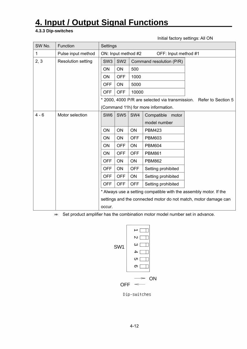
4.3.3 Dip-switches
Initial factory settings: All ON
SW No. Function Settings
1 Pulse input method ON: Input method #2 OFF: Input method #1
2, 3
Resolution setting
SW3 SW2 Command resolution (P/R)
ON ON 500
ON OFF 1000
OFF ON 5000
OFF OFF 10000
* 2000, 4000 P/R are selected via transmission. Refer to Section 5
(Command 11h) for more information.
4 - 6 Motor selection SW6 SW5 SW4 Compatible motor
model number
ON ON ON PBM423
ON ON OFF PBM603
ON OFF ON PBM604
ON OFF OFF PBM861
OFF ON ON PBM862
OFF ON OFF Setting prohibited
OFF OFF ON Setting prohibited
OFF OFF OFF Setting prohibited
* Always use a setting compatible with the assembly motor. If the
settings and the connected motor do not match, motor damage can
occur.
* Set product amplifier has the combination motor model number set in advance.
ONOFF
SW1
12
34
56
Dip-switches
4. Input / Output Signal Functions
4-13
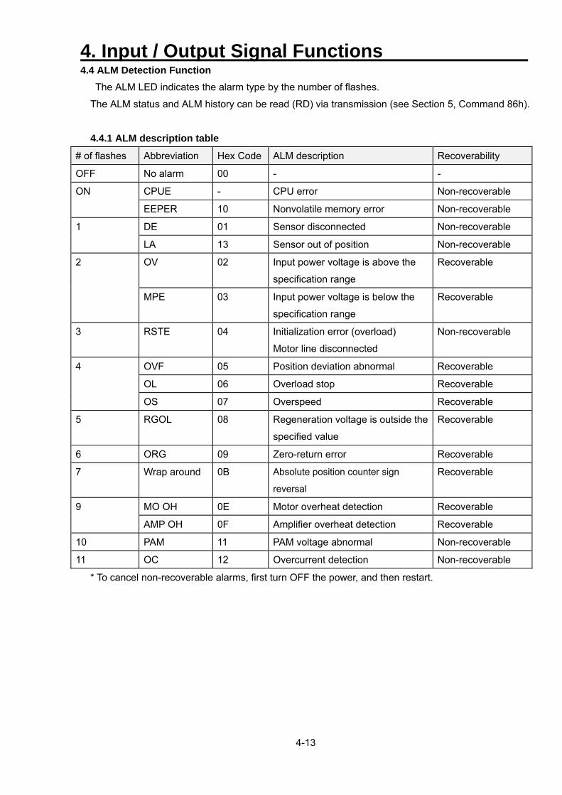
4.4 ALM Detection Function The ALM LED indicates the alarm type by the number of flashes.
The ALM status and ALM history can be read (RD) via transmission (see Section 5, Command 86h).
4.4.1 ALM description table
# of flashes Abbreviation Hex Code ALM description Recoverability
OFF No alarm 00 - -
CPUE - CPU error Non-recoverable ON
EEPER 10 Nonvolatile memory error Non-recoverable
DE 01 Sensor disconnected Non-recoverable 1
LA 13 Sensor out of position Non-recoverable
OV 02 Input power voltage is above the
specification range
Recoverable 2
MPE 03 Input power voltage is below the
specification range
Recoverable
3 RSTE 04 Initialization error (overload)
Motor line disconnected
Non-recoverable
OVF 05 Position deviation abnormal Recoverable
OL 06 Overload stop Recoverable
4
OS 07 Overspeed Recoverable
5 RGOL 08 Regeneration voltage is outside the
specified value
Recoverable
6 ORG 09 Zero-return error Recoverable
7 Wrap around 0B Absolute position counter sign
reversal
Recoverable
MO OH 0E Motor overheat detection Recoverable 9
AMP OH 0F Amplifier overheat detection Recoverable
10 PAM 11 PAM voltage abnormal Non-recoverable
11 OC 12 Overcurrent detection Non-recoverable
* To cancel non-recoverable alarms, first turn OFF the power, and then restart.
4. Input / Output Signal Functions
4-14
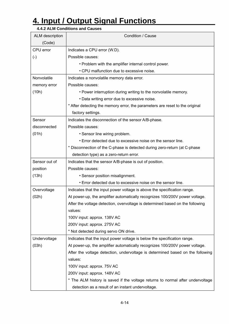
4.4.2 ALM Conditions and Causes
ALM description
(Code)
Condition / Cause
CPU error
(-)
Indicates a CPU error (W.D).
Possible causes:
・ Problem with the amplifier internal control power.
・ CPU malfunction due to excessive noise.
Nonvolatile
memory error
(10h)
Indicates a nonvolatile memory data error.
Possible causes:
・ Power interruption during writing to the nonvolatile memory.
・ Data writing error due to excessive noise.
* After detecting the memory error, the parameters are reset to the original
factory settings.
Sensor
disconnected
(01h)
Indicates the disconnection of the sensor A/B-phase.
Possible causes:
・ Sensor line wiring problem.
・ Error detected due to excessive noise on the sensor line.
* Disconnection of the C-phase is detected during zero-return (at C-phase
detection type) as a zero-return error.
Sensor out of
position
(13h)
Indicates that the sensor A/B-phase is out of position.
Possible causes:
・ Sensor position misalignment.
・ Error detected due to excessive noise on the sensor line.
Overvoltage
(02h)
Indicates that the input power voltage is above the specification range.
At power-up, the amplifier automatically recognizes 100/200V power voltage.
After the voltage detection, overvoltage is determined based on the following
values:
100V input: approx. 138V AC
200V input: approx. 275V AC
* Not detected during servo ON drive.
Undervoltage
(03h)
Indicates that the input power voltage is below the specification range.
At power-up, the amplifier automatically recognizes 100/200V power voltage.
After the voltage detection, undervoltage is determined based on the following
values:
100V input: approx. 75V AC
200V input: approx. 148V AC
* The ALM history is saved if the voltage returns to normal after undervoltage
detection as a result of an instant undervoltage.
4. Input / Output Signal Functions
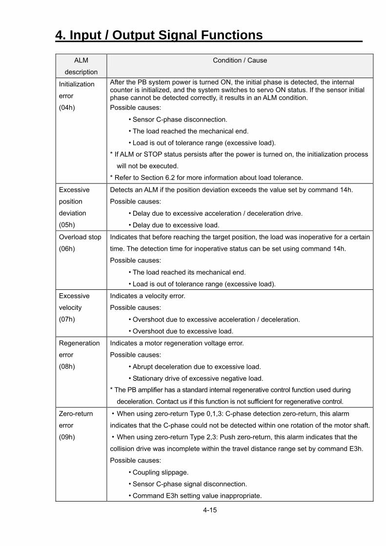
4-15
ALM
description
Condition / Cause
Initialization
error
(04h)
After the PB system power is turned ON, the initial phase is detected, the internal counter is initialized, and the system switches to servo ON status. If the sensor initial phase cannot be detected correctly, it results in an ALM condition. Possible causes:
・ Sensor C-phase disconnection.
・ The load reached the mechanical end.
・ Load is out of tolerance range (excessive load).
* If ALM or STOP status persists after the power is turned on, the initialization process
will not be executed.
* Refer to Section 6.2 for more information about load tolerance.
Excessive
position
deviation
(05h)
Detects an ALM if the position deviation exceeds the value set by command 14h.
Possible causes:
・ Delay due to excessive acceleration / deceleration drive.
・ Delay due to excessive load.
Overload stop
(06h)
Indicates that before reaching the target position, the load was inoperative for a certain
time. The detection time for inoperative status can be set using command 14h.
Possible causes:
・ The load reached its mechanical end.
・ Load is out of tolerance range (excessive load).
Excessive
velocity
(07h)
Indicates a velocity error.
Possible causes:
・ Overshoot due to excessive acceleration / deceleration.
・ Overshoot due to excessive load.
Regeneration
error
(08h)
Indicates a motor regeneration voltage error.
Possible causes:
・ Abrupt deceleration due to excessive load.
・ Stationary drive of excessive negative load.
* The PB amplifier has a standard internal regenerative control function used during
deceleration. Contact us if this function is not sufficient for regenerative control.
Zero-return
error
(09h)
・When using zero-return Type 0,1,3: C-phase detection zero-return, this alarm
indicates that the C-phase could not be detected within one rotation of the motor shaft.
・When using zero-return Type 2,3: Push zero-return, this alarm indicates that the
collision drive was incomplete within the travel distance range set by command E3h.
Possible causes:
・ Coupling slippage.
・ Sensor C-phase signal disconnection.
・ Command E3h setting value inappropriate.
4. Input / Output Signal Functions
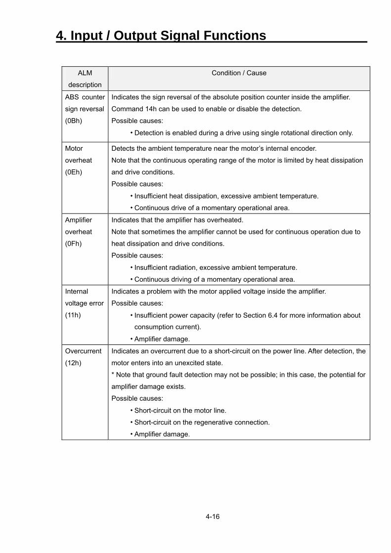
4-16
ALM
description
Condition / Cause
ABS counter
sign reversal
(0Bh)
Indicates the sign reversal of the absolute position counter inside the amplifier.
Command 14h can be used to enable or disable the detection.
Possible causes:
・ Detection is enabled during a drive using single rotational direction only.
Motor
overheat
(0Eh)
Detects the ambient temperature near the motor’s internal encoder.
Note that the continuous operating range of the motor is limited by heat dissipation
and drive conditions.
Possible causes:
・ Insufficient heat dissipation, excessive ambient temperature.
・ Continuous drive of a momentary operational area.
Amplifier
overheat
(0Fh)
Indicates that the amplifier has overheated.
Note that sometimes the amplifier cannot be used for continuous operation due to
heat dissipation and drive conditions.
Possible causes:
・ Insufficient radiation, excessive ambient temperature.
・ Continuous driving of a momentary operational area.
Internal
voltage error
(11h)
Indicates a problem with the motor applied voltage inside the amplifier.
Possible causes:
・ Insufficient power capacity (refer to Section 6.4 for more information about
consumption current).
・ Amplifier damage.
Overcurrent
(12h)
Indicates an overcurrent due to a short-circuit on the power line. After detection, the
motor enters into an unexcited state.
* Note that ground fault detection may not be possible; in this case, the potential for
amplifier damage exists.
Possible causes:
・ Short-circuit on the motor line.
・ Short-circuit on the regenerative connection.
・ Amplifier damage.
4. Input / Output Signal Functions
4-17
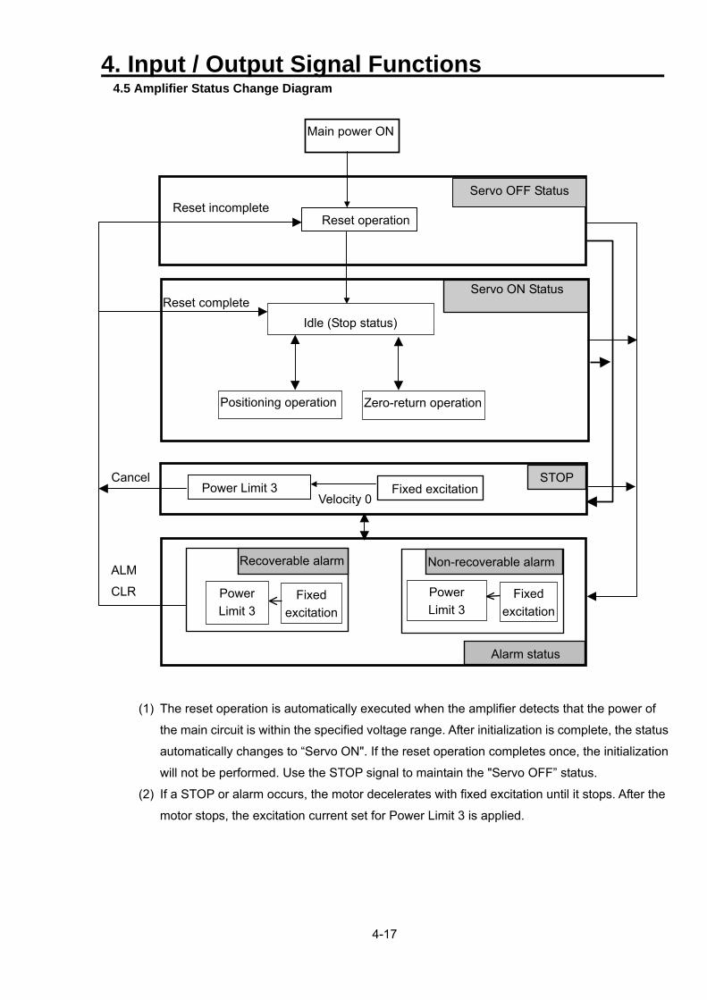
4.5 Amplifier Status Change Diagram
Reset complete Servo ON Status
Zero-return operationPositioning operation
Idle (Stop status)
Reset operation
Servo OFF Status
STOP Fixed excitation
Velocity 0Power Limit 3
Alarm status
Non-recoverable alarm
Fixed excitation
Power Limit 3
Recoverable alarm
Fixed excitation
Power Limit 3
Cancel
ALM
CLR
Reset incomplete
Main power ON
(1) The reset operation is automatically executed when the amplifier detects that the power of
the main circuit is within the specified voltage range. After initialization is complete, the status
automatically changes to “Servo ON". If the reset operation completes once, the initialization
will not be performed. Use the STOP signal to maintain the "Servo OFF” status.
(2) If a STOP or alarm occurs, the motor decelerates with fixed excitation until it stops. After the
motor stops, the excitation current set for Power Limit 3 is applied.
4. Input / Output Signal Functions
4-18
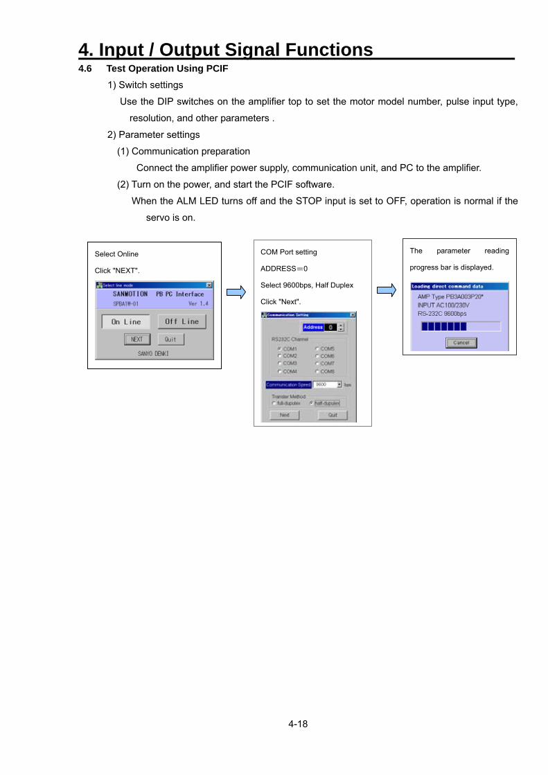
4.6 Test Operation Using PCIF
1) Switch settings
Use the DIP switches on the amplifier top to set the motor model number, pulse input type,
resolution, and other parameters .
2) Parameter settings
(1) Communication preparation
Connect the amplifier power supply, communication unit, and PC to the amplifier.
(2) Turn on the power, and start the PCIF software.
When the ALM LED turns off and the STOP input is set to OFF, operation is normal if the
servo is on.
COM Port setting
ADDRESS=0
Select 9600bps, Half Duplex
Click "Next".
The parameter reading
progress bar is displayed.
Select Online
Click "NEXT".
4. Input / Output Signal Functions
4-19
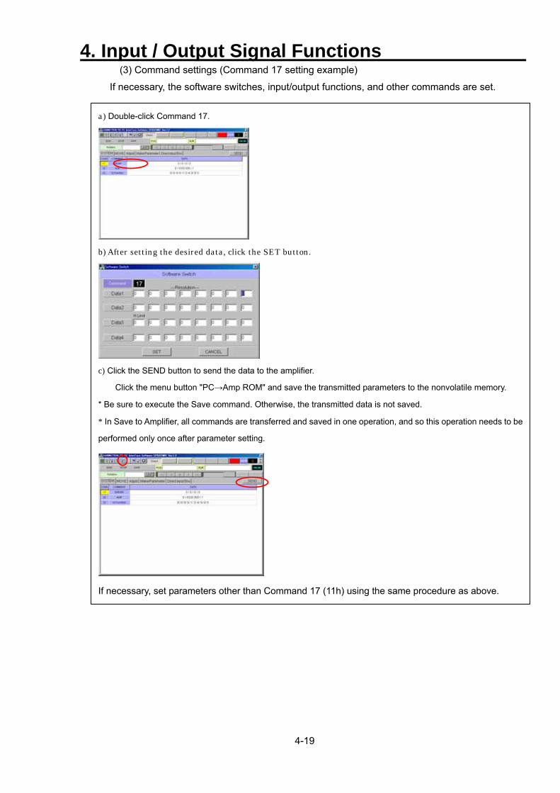
(3) Command settings (Command 17 setting example)
If necessary, the software switches, input/output functions, and other commands are set.
a) Double-click Command 17.
b) After setting the desired data, click the SET button.
c) Click the SEND button to send the data to the amplifier.
Click the menu button "PC→Amp ROM" and save the transmitted parameters to the nonvolatile memory.
* Be sure to execute the Save command. Otherwise, the transmitted data is not saved.
* In Save to Amplifier, all commands are transferred and saved in one operation, and so this operation needs to be
performed only once after parameter setting.
If necessary, set parameters other than Command 17 (11h) using the same procedure as above.
4. Input / Output Signal Functions
4-20
3)Operation
ⅰ)After the parameter setting is completed, turn the power off and connect wiring for the motor
power, encoder and I / O.
* Refer to Chapter 3 to ensure the correct wiring.
* Perform safety check and attach the motor to the fixed plate etc. For safety, set up
the emergency stop circuit before operating.
ii)Turn the power on again after confirming that the STOP input signal is cancelled. If the Power
LED Lights and ALM LED Lights out, it is normal.
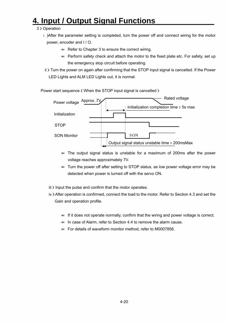
Power start sequence(When the STOP input signal is cancelled)
SON
Initialization completion time:5s maxApprox. 7V. Rated voltage
Output signal status unstable time:200msMax
Power voltage
Initialization
STOP
SON Monitor
* The output signal status is unstable for a maximum of 200ms after the power
voltage reaches approximately 7V.
* Turn the power off after setting to STOP status, as low power voltage error may be
detected when power is turned off with the servo ON.
iii)Input the pulse and confirm that the motor operates.
iv)After operation is confirmed, connect the load to the motor. Refer to Section 4.3 and set the
Gain and operation profile.
* If it does not operate normally, confirm that the wiring and power voltage is correct.
* In case of Alarm, refer to Section 4.4 to remove the alarm cause.
* For details of waveform monitor method, refer to M0007856.
5. Commands(Communication)
5-1
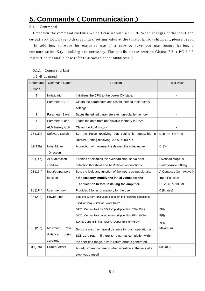
5.1 Command I mention the command contents which I can set with a PC I/F. When changes of the input and output Port logic have to change initial setting value at the time of factory shipment, please use it. In addition, software for exclusive use of a case to have you use communication, a communication Kay - bulldog are necessary. The details please refer to Clause 7.3. ( PC I / F instruction manual please refer to attached sheet M0007856.)
5.1.1 Command List 1)WR command
Command
Code
Command Name Function Initial Value
1 Initialization Initializes the CPU to the power ON state. -
2 Parameter CLR Clears the parameters and resets them to their factory
settings.
-
3 Parameter Save Saves the edited parameters to non-volatile memory. -
4 Parameter Load Loads the data from non-volatile memory to RAM. -
6 ALM history CLR Clears the ALM history. -
17 (11h) Software switch Set the Pulse resolving that setting is impossible in
DIPSW. Setting resolving: 2000, 4000P/R
Dip SW Enable
19(13h) Initial Move
Direction
A direction of movement is defined the initial move. 0:CW
20 (14h) ALM detection
condition
Enables or disables the overload stop, servo error
detection threshold and ALM detection functions.
Overload stop=8s
Servo error=360deg
22 (16h) Input/output port
function
Sets the logic and function of the input / output signals.
* If necessary, modify the initial values for the
application before installing the amplifier.
A Contact(On Active)
Input Function
DEV CLR/HOME
31 (1Fh) User memory Provides 8 bytes of memory for the user. 0 (8bytes)
32 (20h) Power Limit Sets the current limit value based on the following conditions:
used for Torque limit or Power Down.
DAT1: Current limit for SON stop. (Upper limit 7Fh=50%)
DAT2: Current limit during motion (Upper limit FFh=100%)
DAT3: Current limit for SOFF. (Upper limit 7Fh=50%)
7Fh
FFh
7Fh 35 (23h) Maximum travel
distance during
zero-return
Sets the maximum travel distance for push operation and
SDN zero-return. If there is no normal completion within
the specified range, a zero-return error is generated.
Maximum
39(27h) Current offset An adjustment command when vibration at the time of a
stop was caused
0064h,0
5. Commands(Communication)
5-2
Command
Code
Command Name Function Initial Value
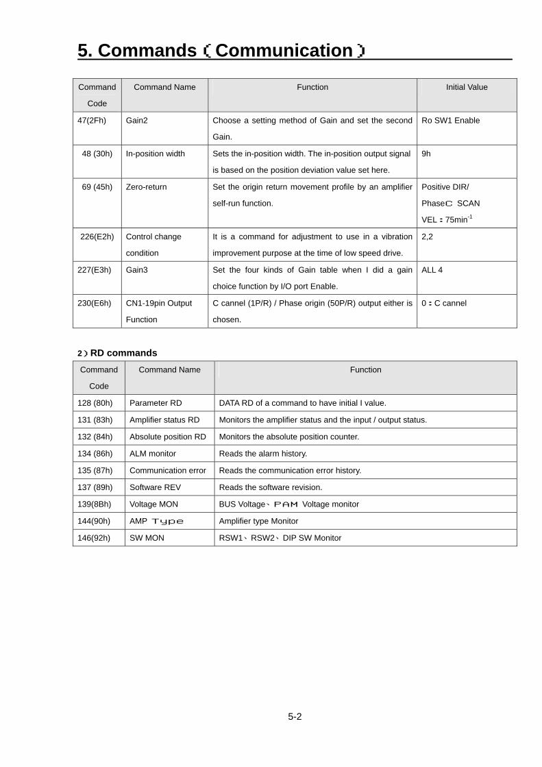
47(2Fh) Gain2 Choose a setting method of Gain and set the second
Gain.
Ro SW1 Enable
48 (30h) In-position width Sets the in-position width. The in-position output signal
is based on the position deviation value set here.
9h
69 (45h) Zero-return Set the origin return movement profile by an amplifier
self-run function.
Positive DIR/
PhaseC SCAN
VEL:75min-1
226(E2h) Control change
condition
It is a command for adjustment to use in a vibration
improvement purpose at the time of low speed drive.
2,2
227(E3h) Gain3 Set the four kinds of Gain table when I did a gain
choice function by I/O port Enable.
ALL 4
230(E6h) CN1-19pin Output
Function
C cannel (1P/R) / Phase origin (50P/R) output either is
chosen.
0:C cannel
2)RD commands
Command
Code
Command Name Function
128 (80h) Parameter RD DATA RD of a command to have initial I value.
131 (83h) Amplifier status RD Monitors the amplifier status and the input / output status.
132 (84h) Absolute position RD Monitors the absolute position counter.
134 (86h) ALM monitor Reads the alarm history.
135 (87h) Communication error Reads the communication error history.
137 (89h) Software REV Reads the software revision.
139(8Bh) Voltage MON BUS Voltage、PAM Voltage monitor
144(90h) AMP Type Amplifier type Monitor
146(92h) SW MON RSW1、RSW2、DIP SW Monitor
5. Commands(Communication)
5-3
5.1.2 Commands
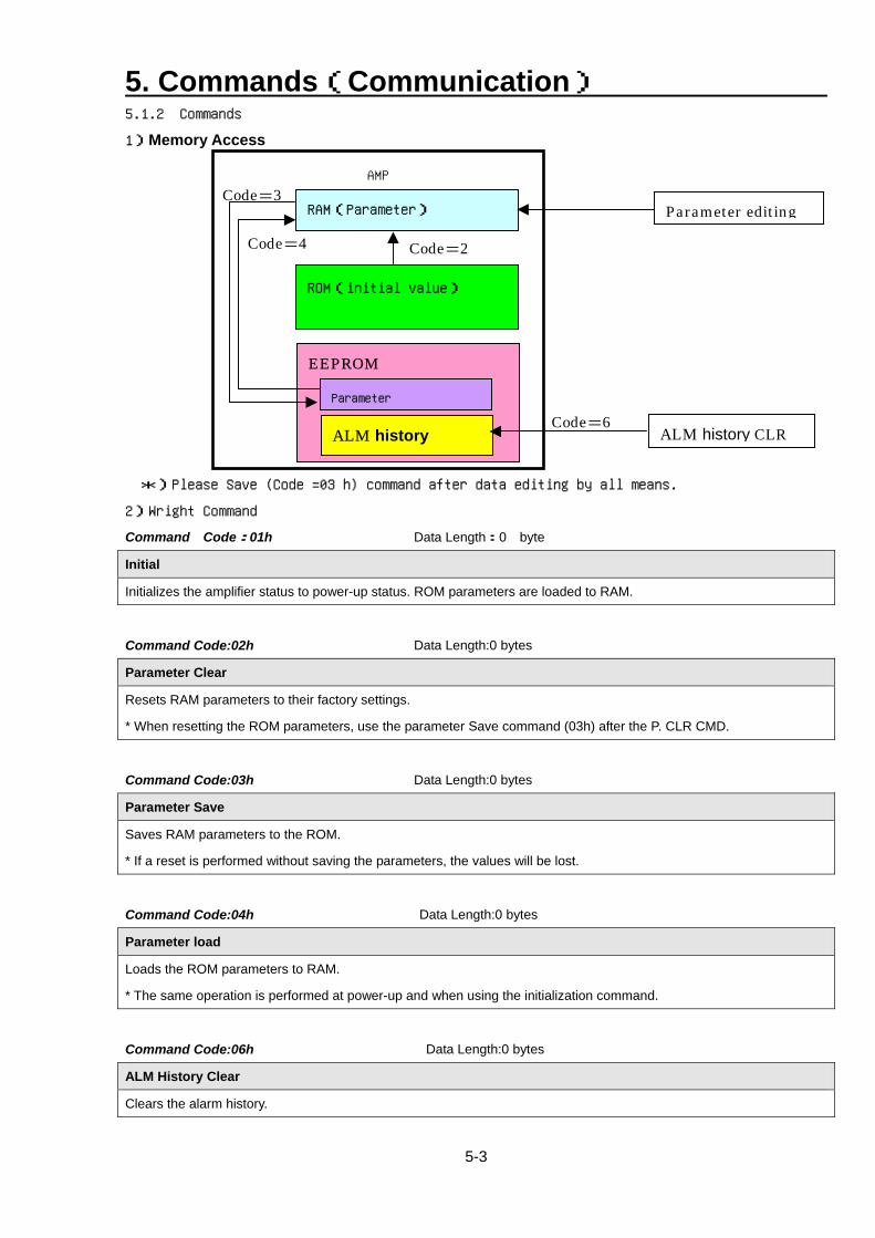
1)Memory Access
*)Please Save (Code =03 h) command after data editing by all means.
2)Wright Command
Command Code:01h Data Length:0 byte
Initial
Initializes the amplifier status to power-up status. ROM parameters are loaded to RAM.
Command Code:02h Data Length:0 bytes
Parameter Clear
Resets RAM parameters to their factory settings.
* When resetting the ROM parameters, use the parameter Save command (03h) after the P. CLR CMD.
Command Code:03h Data Length:0 bytes
Parameter Save
Saves RAM parameters to the ROM.
* If a reset is performed without saving the parameters, the values will be lost.
Command Code:04h Data Length:0 bytes
Parameter load
Loads the ROM parameters to RAM.
* The same operation is performed at power-up and when using the initialization command.
Command Code:06h Data Length:0 bytes
ALM History Clear
Clears the alarm history.
AMP
RAM(Parameter)
EEPROM Parameter
ALM history
ROM(initial value)
Code=2
Code=6 ALM history CLR
Code=4
Code=3 Parameter editing
5. Commands(Communication)
5-4
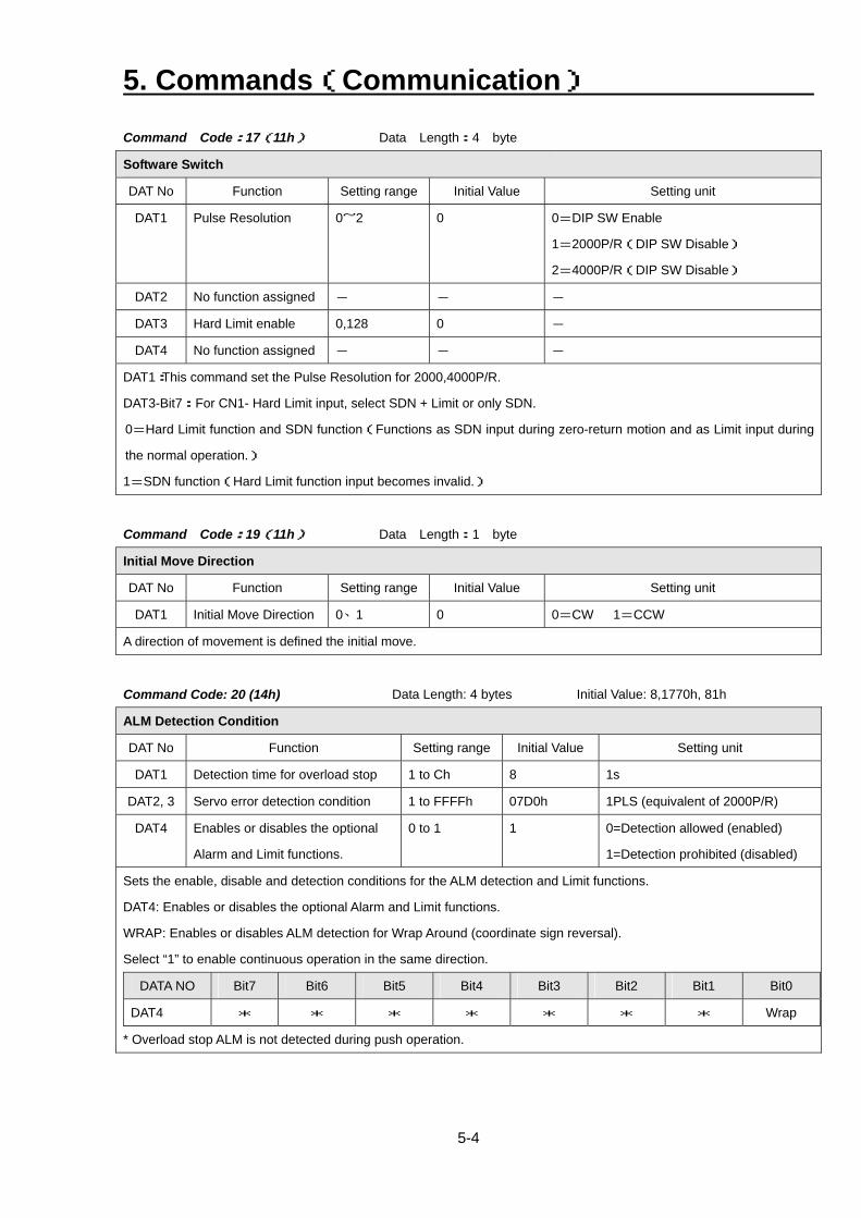
Command Code:17(11h) Data Length:4 byte
Software Switch
DAT No Function Setting range Initial Value Setting unit
DAT1 Pulse Resolution 0~2 0 0=DIP SW Enable
1=2000P/R(DIP SW Disable)
2=4000P/R(DIP SW Disable)
DAT2 No function assigned - - -
DAT3 Hard Limit enable 0,128 0 -
DAT4 No function assigned - - -
DAT1:This command set the Pulse Resolution for 2000,4000P/R.
DAT3-Bit7:For CN1- Hard Limit input, select SDN + Limit or only SDN.
0=Hard Limit function and SDN function(Functions as SDN input during zero-return motion and as Limit input during
the normal operation.)
1=SDN function(Hard Limit function input becomes invalid.)
Command Code:19(11h) Data Length:1 byte
Initial Move Direction
DAT No Function Setting range Initial Value Setting unit
DAT1 Initial Move Direction 0、1 0 0=CW 1=CCW
A direction of movement is defined the initial move.
Command Code: 20 (14h) Data Length: 4 bytes Initial Value: 8,1770h, 81h
ALM Detection Condition
DAT No Function Setting range Initial Value Setting unit
DAT1 Detection time for overload stop 1 to Ch 8 1s
DAT2, 3 Servo error detection condition 1 to FFFFh 07D0h 1PLS (equivalent of 2000P/R)
DAT4 Enables or disables the optional
Alarm and Limit functions.
0 to 1 1 0=Detection allowed (enabled)
1=Detection prohibited (disabled)
Sets the enable, disable and detection conditions for the ALM detection and Limit functions.
DAT4: Enables or disables the optional Alarm and Limit functions.
WRAP: Enables or disables ALM detection for Wrap Around (coordinate sign reversal).
Select “1” to enable continuous operation in the same direction.
DATA NO Bit7 Bit6 Bit5 Bit4 Bit3 Bit2 Bit1 Bit0
DAT4 * * * * * * * Wrap
* Overload stop ALM is not detected during push operation.
5. Commands(Communication)
5-5
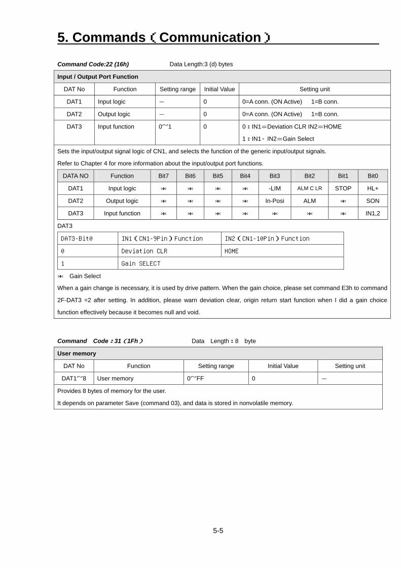
Command Code:22 (16h) Data Length:3 (d) bytes
Input / Output Port Function
DAT No Function Setting range Initial Value Setting unit
DAT1 Input logic - 0 0=A conn. (ON Active) 1=B conn.
DAT2 Output logic - 0 0=A conn. (ON Active) 1=B conn.
DAT3 Input function 0~1 0 0:IN1=Deviation CLR IN2=HOME
1:IN1、IN2=Gain Select
Sets the input/output signal logic of CN1, and selects the function of the generic input/output signals.
Refer to Chapter 4 for more information about the input/output port functions.
DATA NO Function Bit7 Bit6 Bit5 Bit4 Bit3 Bit2 Bit1 Bit0
DAT1 Input logic * * * * -LIM ALM C LR STOP HL+
DAT2 Output logic * * * * In-Posi ALM * SON
DAT3 Input function * * * * * * * IN1,2
DAT3
DAT3-Bit0 IN1(CN1-9Pin)Function IN2(CN1-10Pin)Function
0 Deviation CLR HOME
1 Gain SELECT
* Gain Select
When a gain change is necessary, it is used by drive pattern. When the gain choice, please set command E3h to command
2F-DAT3 =2 after setting. In addition, please warn deviation clear, origin return start function when I did a gain choice
function effectively because it becomes null and void.
Command Code:31(1Fh) Data Length:8 byte
User memory
DAT No Function Setting range Initial Value Setting unit
DAT1~8 User memory 0~FF 0 -
Provides 8 bytes of memory for the user.
It depends on parameter Save (command 03), and data is stored in nonvolatile memory.
5. Commands(Communication)
5-6
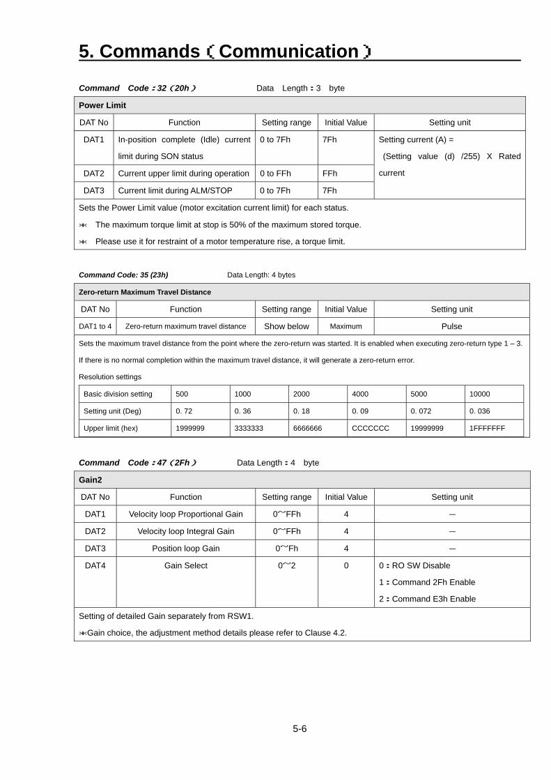
Command Code:32(20h) Data Length:3 byte
Power Limit
DAT No Function Setting range Initial Value Setting unit
DAT1 In-position complete (Idle) current
limit during SON status
0 to 7Fh 7Fh
DAT2 Current upper limit during operation 0 to FFh FFh
DAT3 Current limit during ALM/STOP 0 to 7Fh 7Fh
Setting current (A) =
(Setting value (d) /255) X Rated
current
Sets the Power Limit value (motor excitation current limit) for each status.
* The maximum torque limit at stop is 50% of the maximum stored torque.
* Please use it for restraint of a motor temperature rise, a torque limit.
Command Code: 35 (23h) Data Length: 4 bytes
Zero-return Maximum Travel Distance
DAT No Function Setting range Initial Value Setting unit
DAT1 to 4 Zero-return maximum travel distance Show below Maximum Pulse
Sets the maximum travel distance from the point where the zero-return was started. It is enabled when executing zero-return type 1 – 3.
If there is no normal completion within the maximum travel distance, it will generate a zero-return error.
Resolution settings
Basic division setting 500 1000 2000 4000 5000 10000
Setting unit (Deg) 0. 72 0. 36 0. 18 0. 09 0. 072 0. 036
Upper limit (hex) 1999999 3333333 6666666 CCCCCCC 19999999 1FFFFFFF
Command Code:47(2Fh) Data Length:4 byte
Gain2
DAT No Function Setting range Initial Value Setting unit
DAT1 Velocity loop Proportional Gain 0~FFh 4 -
DAT2 Velocity loop Integral Gain 0~FFh 4 -
DAT3 Position loop Gain 0~Fh 4 -
DAT4 Gain Select 0~2 0 0:RO SW Disable
1:Command 2Fh Enable
2:Command E3h Enable
Setting of detailed Gain separately from RSW1.
*Gain choice, the adjustment method details please refer to Clause 4.2.
5. Commands(Communication)
5-7
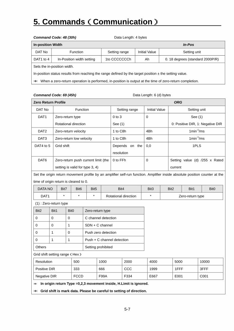
Command Code: 48 (30h) Data Length: 4 bytes
In-position Width In-Pos
DAT No Function Setting range Initial Value Setting unit
DAT1 to 4 In-Position width setting 1to CCCCCCCh Ah 0. 18 degrees (standard 2000P/R)
Sets the in-position width.
In-position status results from reaching the range defined by the target position ± the setting value.
* When a zero-return operation is performed, in-position is output at the time of zero-return completion.
Command Code: 69 (45h) Data Length: 6 (d) bytes
Zero Return Profile ORG
DAT No Function Setting range Initial Value Setting unit
DAT1 Zero-return type
Rotational direction
0 to 3
See (1)
0 See (1)
0: Positive DIR, 1: Negative DIR
DAT2 Zero-return velocity 1 to C8h 4Bh 1min-1/ms
DAT3 Zero-return low velocity 1 to C8h 4Bh 1min-1/ms
DAT4 to 5 Grid shift Depends on the
resolution
0,0 1PLS
DAT6 Zero-return push current limit (the
setting is valid for type 3, 4)
0 to FFh 0 Setting value (d) /255 x Rated
current
Set the origin return movement profile by an amplifier self-run function. Amplifier inside absolute position counter at the
time of origin return is cleared to 0.
DATA NO Bit7 Bit6 Bit5 Bit4 Bit3 Bit2 Bit1 Bit0
DAT1 * * * Rotational direction * Zero-return type
(1) : Zero-return type
Bit2 Bit1 Bit0 Zero-return type
0 0 0 C channel detection
0 0 1 SDN + C channel
0 1 0 Push zero detection
0 1 1 Push + C channel detection
Others Setting prohibited
Grid shift setting range(Hex)
Resolution 500 1000 2000 4000 5000 10000
Positive DIR 333 666 CCC 1999 1FFF 3FFF
Negative DIR FCCD F99A F334 E667 E001 C001
* In origin return Type =0,2,3 movement inside, H.Limit is ignored.
* Grid shift is mark data. Please be careful to setting of direction.
5. Commands(Communication)
5-8
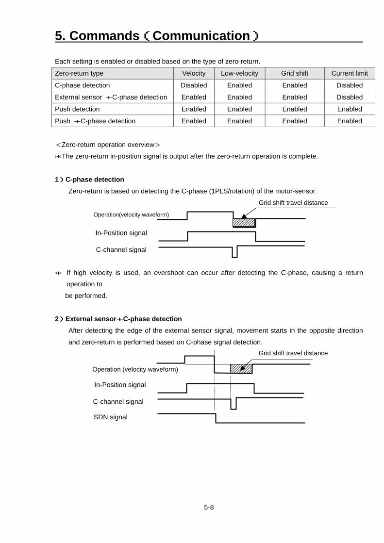
Each setting is enabled or disabled based on the type of zero-return.
Zero-return type Velocity Low-velocity Grid shift Current limit
C-phase detection Disabled Enabled Enabled Disabled
External sensor +C-phase detection Enabled Enabled Enabled Disabled
Push detection Enabled Enabled Enabled Enabled
Push +C-phase detection Enabled Enabled Enabled Enabled
<Zero-return operation overview>
*The zero-return in-position signal is output after the zero-return operation is complete.
1)C-phase detection Zero-return is based on detecting the C-phase (1PLS/rotation) of the motor-sensor.
Operation(velocity waveform)
In-Position signal
C-channel signal
Grid shift travel distance
* If high velocity is used, an overshoot can occur after detecting the C-phase, causing a return
operation to
be performed.
2)External sensor+C-phase detection
After detecting the edge of the external sensor signal, movement starts in the opposite direction
and zero-return is performed based on C-phase signal detection.
Operation (velocity waveform)
In-Position signal
C-channel signal
Grid shift travel distance
SDN signal
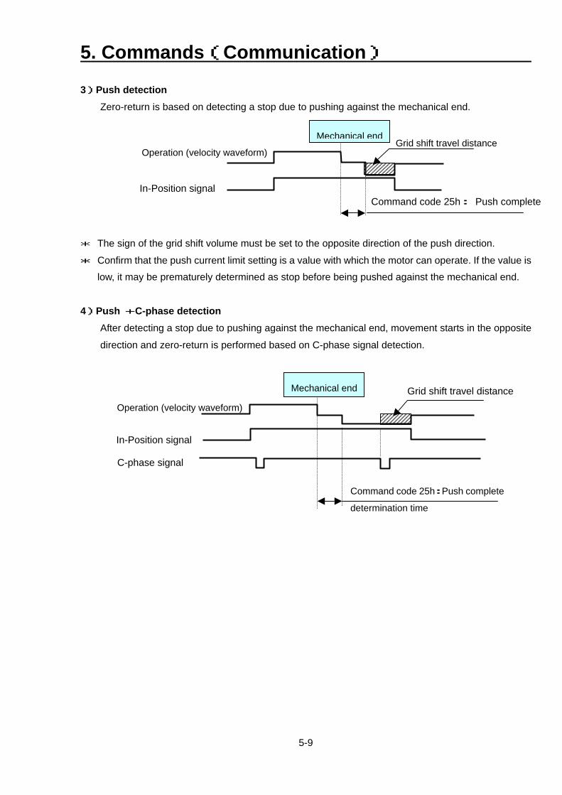
5. Commands(Communication)
5-9
3)Push detection Zero-return is based on detecting a stop due to pushing against the mechanical end.
Operation (velocity waveform)Grid shift travel distance
Mechanical end
In-Position signal
Command code 25h: Push complete
* The sign of the grid shift volume must be set to the opposite direction of the push direction.
* Confirm that the push current limit setting is a value with which the motor can operate. If the value is
low, it may be prematurely determined as stop before being pushed against the mechanical end. 4)Push +C-phase detection
After detecting a stop due to pushing against the mechanical end, movement starts in the opposite
direction and zero-return is performed based on C-phase signal detection.
Operation (velocity waveform)
In-Position signal
Grid shift travel distance
C-phase signal
Command code 25h:Push complete
determination time
Mechanical end
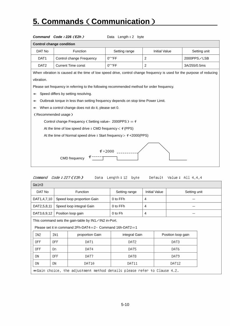
5. Commands(Communication)
5-10
Command Code:226(E2h) Data Length:2 byte
Control change condition
DAT No Function Setting range Initial Value Setting unit
DAT1 Control change Frequency 0~FF 2 2000PPS/LSB
DAT2 Current Time const 0~FF 2 3A/255/0.5ms
When vibration is caused at the time of low speed drive, control change frequency is used for the purpose of reducing
vibration.
Please set frequency in referring to the following recommended method for order frequency.
* Speed differs by setting resolving.
* Outbreak torque in less than setting frequency depends on stop time Power Limit.
* When a control change does not do it, please set 0.
(Recommended usage)
Control change Frequency(Setting value×2000PPS)=f
At the time of low speed drive:CMD frequency<f(PPS)
At the time of Normal speed drive:Start frequency>f+2000(PPS)
f+2000 f CMD frequency
Command Code:227(E3h) Data Length:12 byte Default Value: All 4,4,4
Gain3
DAT No Function Setting range Initial Value Setting unit
DAT1,4,7,10 Speed loop proportion Gain 0 to FFh 4 -
DAT2,5,8,11 Speed loop integral Gain 0 to FFh 4 -
DAT3,6,9,12 Position loop gain 0 to Fh 4 -
This command sets the gain-table by IN1/IN2 in-Port.
Please set it in command 2Fh-DAT4=2、Command 16h-DAT2=1
IN2 IN1 proportion Gain integral Gain Position loop gain
OFF OFF DAT1 DAT2 DAT3
OFF On DAT4 DAT5 DAT6
ON OFF DAT7 DAT8 DAT9
ON ON DAT10 DAT11 DAT12
*Gain choice, the adjustment method details please refer to Clause 4.2.
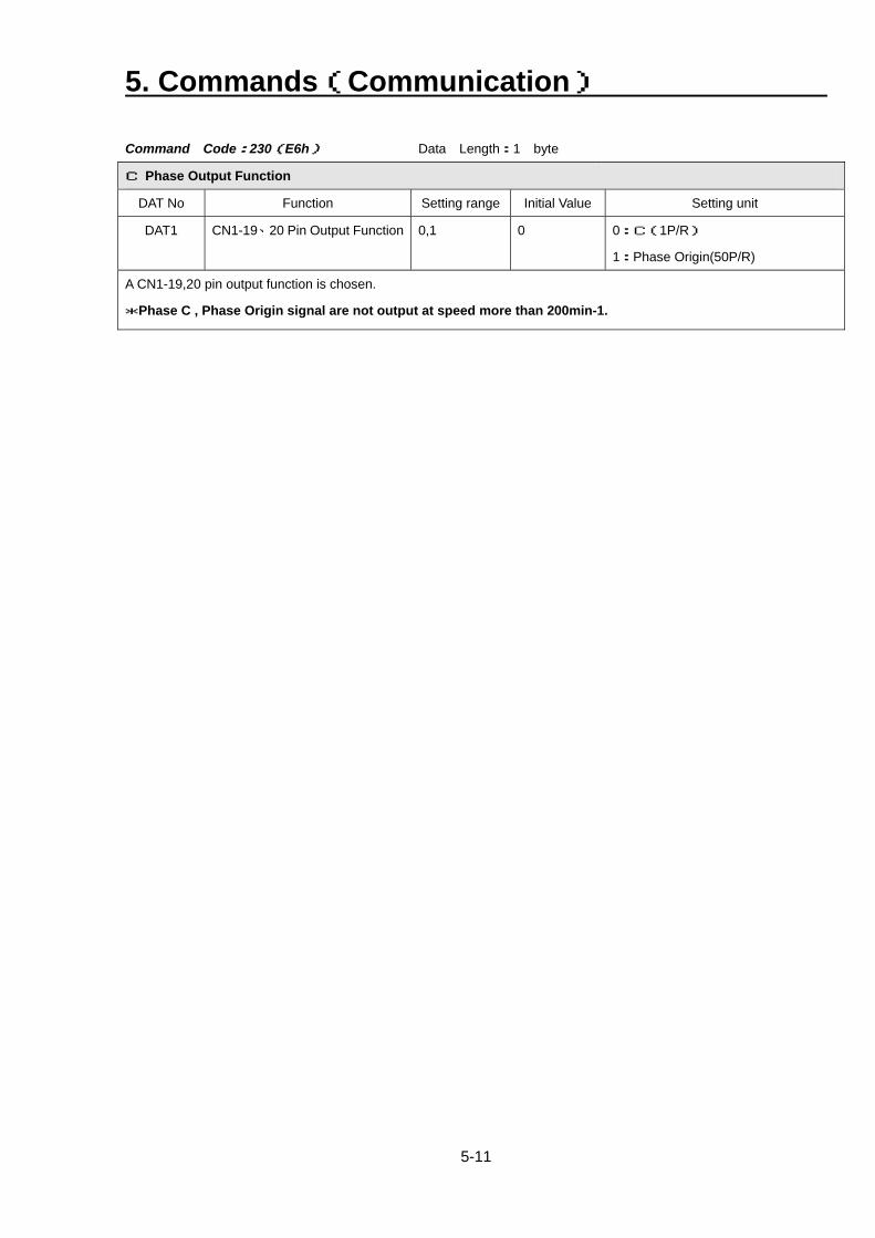
5. Commands(Communication)
5-11
Command Code:230(E6h) Data Length:1 byte
C Phase Output Function
DAT No Function Setting range Initial Value Setting unit
DAT1 CN1-19、20 Pin Output Function 0,1 0 0:C(1P/R)
1:Phase Origin(50P/R)
A CN1-19,20 pin output function is chosen.
*Phase C , Phase Origin signal are not output at speed more than 200min-1.
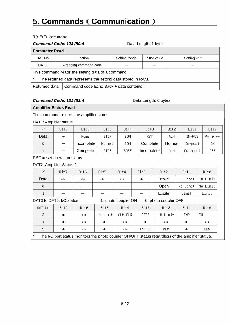
5. Commands(Communication)
5-12
3)RD command Command Code: 128 (80h) Data Length: 1 byte
Parameter Read
DAT No Function Setting range Initial Value Setting unit
DAT1 A reading command code - - -
This command reads the setting data of a command.
* The returned data represents the setting data stored in RAM.
Returned data Command code Echo Back + data contents
Command Code: 131 (83h) Data Length: 0 bytes
Amplifier Status Read
This command returns the amplifier status.
DAT1: Amplifier status 1
/ Bit7 Bit6 Bit5 Bit4 Bit3 Bit2 Bit1 Bit0
Data * Home STOP SON RST ALM IN-POS Main power
0 - Incomplete Normal SON Complete Normal In-posi ON
1 - Complete STOP SOFF Incomplete ALM Out-posi OFF
RST:reset operation status
DAT2: Amplifier Status 2
/ Bit7 Bit6 Bit5 Bit4 Bit3 Bit2 Bit1 Bit0
Data * * * * * Brake -H.Limit +H.Limit
0 - - - - - Open No Limit No Limit
1 - - - - - Excite Limit Limit
DAT3 to DAT5: I/O status 1=photo coupler ON 0=photo coupler OFF
DAT No Bit7 Bit6 Bit5 Bit4 Bit3 Bit2 Bit1 Bit0
3 * * -H.Limit ALM CLR STOP +H.Limit IN2 IN1
4 * * * * * * * *
5 * * * * In-POS ALM * SON
* The I/O port status monitors the photo coupler ON/OFF status regardless of the amplifier status.
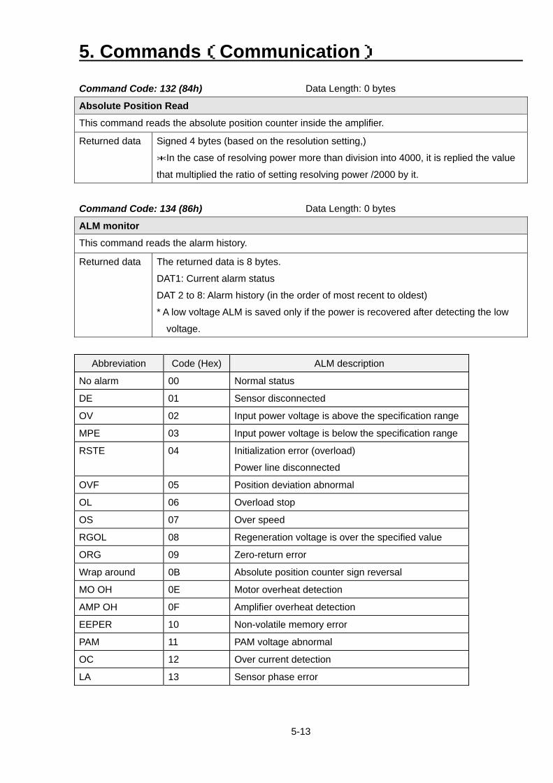
5. Commands(Communication)
5-13
Command Code: 132 (84h) Data Length: 0 bytes
Absolute Position Read
This command reads the absolute position counter inside the amplifier.
Returned data Signed 4 bytes (based on the resolution setting,)
*In the case of resolving power more than division into 4000, it is replied the value
that multiplied the ratio of setting resolving power /2000 by it.
Command Code: 134 (86h) Data Length: 0 bytes
ALM monitor
This command reads the alarm history.
Returned data The returned data is 8 bytes.
DAT1: Current alarm status
DAT 2 to 8: Alarm history (in the order of most recent to oldest)
* A low voltage ALM is saved only if the power is recovered after detecting the low
voltage.
Abbreviation Code (Hex) ALM description
No alarm 00 Normal status
DE 01 Sensor disconnected
OV 02 Input power voltage is above the specification range
MPE 03 Input power voltage is below the specification range
RSTE 04 Initialization error (overload)
Power line disconnected
OVF 05 Position deviation abnormal
OL 06 Overload stop
OS 07 Over speed
RGOL 08 Regeneration voltage is over the specified value
ORG 09 Zero-return error
Wrap around 0B Absolute position counter sign reversal
MO OH 0E Motor overheat detection
AMP OH 0F Amplifier overheat detection
EEPER 10 Non-volatile memory error
PAM 11 PAM voltage abnormal
OC 12 Over current detection
LA 13 Sensor phase error
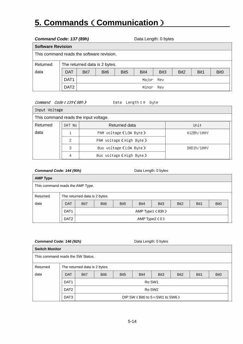
5. Commands(Communication)
5-14
Command Code: 137 (89h) Data Length: 0 bytes
Software Revision
This command reads the software revision.
Returned
data
The returned data is 2 bytes.
DAT Bit7 Bit6 Bit5 Bit4 Bit3 Bit2 Bit1 Bit0
DAT1 Major Rev
DAT2 Minor Rev Command Code:139(8Bh) Data Length:0 byte
Input Voltage
This command reads the input voltage.
Returned
data
DAT No Returned data Unit
1 PAM voltage(LOW Byte)
2 PAM voltage(High Byte)
412Bh/100V
3 Bus voltage(LOW Byte)
4 Bus voltage(High Byte)
30D1h/100V
Command Code: 144 (90h) Data Length: 0 bytes
AMP Type
This command reads the AMP Type.
Returned
data
The returned data is 2 bytes.
DAT Bit7 Bit6 Bit5 Bit4 Bit3 Bit2 Bit1 Bit0
DAT1 AMP Type1(83h)
DAT2 AMP Type2(0)
Command Code: 146 (92h) Data Length: 0 bytes
Switch Monitor
This command reads the SW Status.
Returned
data
The returned data is 2 bytes.
DAT Bit7 Bit6 Bit5 Bit4 Bit3 Bit2 Bit1 Bit0
DAT1 Ro SW1
DAT2 Ro SW2
DAT3 DIP SW(Bit0 to 5=SW1 to SW6)
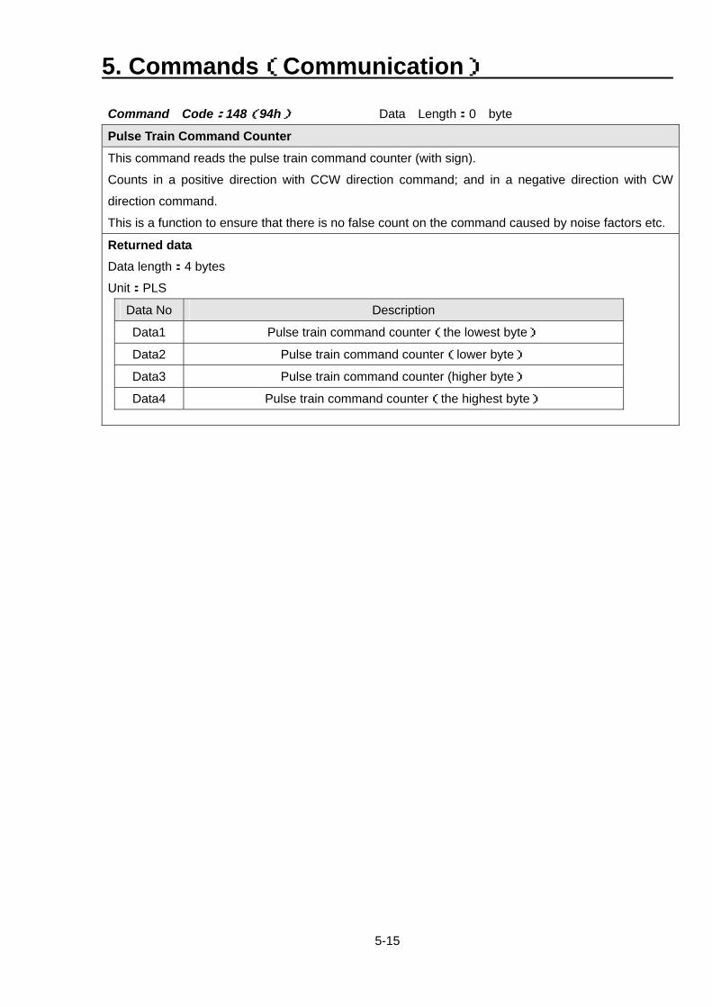
5. Commands(Communication)
5-15
Command Code:148(94h) Data Length:0 byte
Pulse Train Command Counter
This command reads the pulse train command counter (with sign).
Counts in a positive direction with CCW direction command; and in a negative direction with CW
direction command.
This is a function to ensure that there is no false count on the command caused by noise factors etc.
Returned data Data length:4 bytes
Unit:PLS
Data No Description
Data1 Pulse train command counter(the lowest byte)
Data2 Pulse train command counter(lower byte)
Data3 Pulse train command counter (higher byte)
Data4 Pulse train command counter(the highest byte)
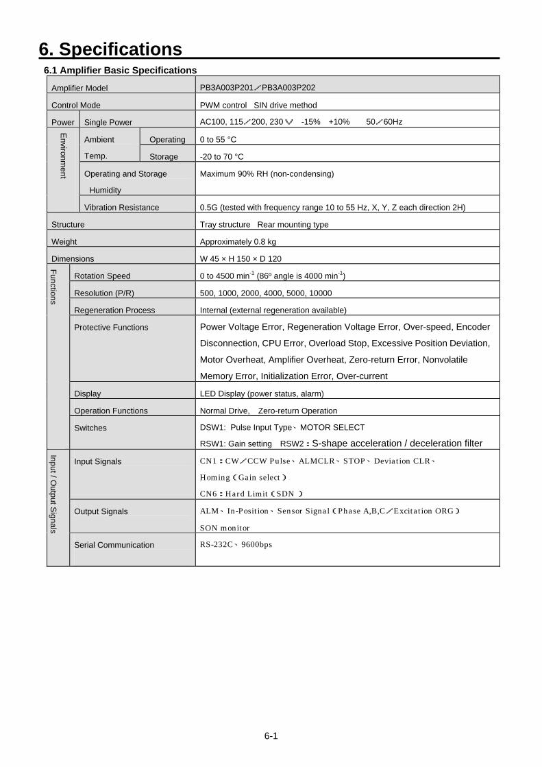
6. Specifications
6-1
6.1 Amplifier Basic Specifications
Amplifier Model PB3A003P201/PB3A003P202
Control Mode PWM control SIN drive method
Power Single Power AC100, 115/200, 230V -15% +10% 50/60Hz
Operating 0 to 55 °C Ambient
Temp. Storage -20 to 70 °C
Operating and Storage
Humidity
Maximum 90% RH (non-condensing)
Environment
Vibration Resistance 0.5G (tested with frequency range 10 to 55 Hz, X, Y, Z each direction 2H)
Structure Tray structure Rear mounting type
Weight Approximately 0.8 kg
Dimensions W 45 × H 150 × D 120
Rotation Speed 0 to 4500 min-1 (86º angle is 4000 min-1)
Resolution (P/R) 500, 1000, 2000, 4000, 5000, 10000
Regeneration Process Internal (external regeneration available)
Protective Functions Power Voltage Error, Regeneration Voltage Error, Over-speed, Encoder
Disconnection, CPU Error, Overload Stop, Excessive Position Deviation,
Motor Overheat, Amplifier Overheat, Zero-return Error, Nonvolatile
Memory Error, Initialization Error, Over-current
Display LED Display (power status, alarm)
Operation Functions Normal Drive, Zero-return Operation
Functions
Switches DSW1: Pulse Input Type、MOTOR SELECT
RSW1: Gain setting RSW2:S-shape acceleration / deceleration filter
Input Signals CN1:CW/CCW Pulse、ALMCLR、STOP、Deviation CLR、
Homing(Gain select)
CN6:Hard Limit(SDN )
Output Signals ALM、In-Position、Sensor Signal(Phase A,B,C/Excitation ORG)
SON monitor
Input / Output S
ignals
Serial Communication
RS-232C、9600bps
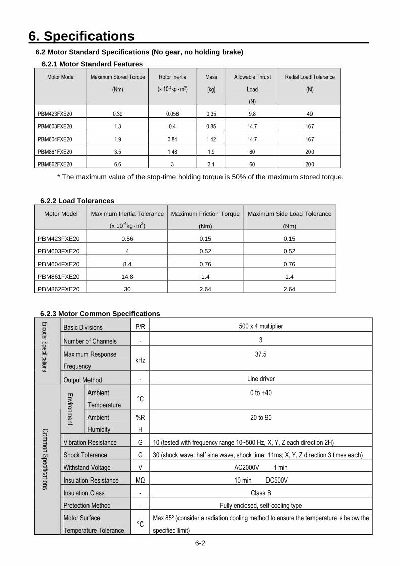
6. Specifications
6-2
6.2 Motor Standard Specifications (No gear, no holding brake) 6.2.1 Motor Standard Features
Motor Model Maximum Stored Torque
(Nm) Rotor Inertia
(x 10-4kg・m2) Mass
[kg] Allowable Thrust
Load
(N)
Radial Load Tolerance
(N)
PBM423FXE20 0.39 0.056 0.35 9.8 49
PBM603FXE20 1.3 0.4 0.85 14.7 167
PBM604FXE20 1.9 0.84 1.42 14.7 167
PBM861FXE20 3.5 1.48 1.9 60 200
PBM862FXE20 6.6 3 3.1 60 200
* The maximum value of the stop-time holding torque is 50% of the maximum stored torque.
6.2.2 Load Tolerances
Motor Model Maximum Inertia Tolerance
(x 10-4kg・m2) Maximum Friction Torque
(Nm)
Maximum Side Load Tolerance
(Nm)
PBM423FXE20 0.56 0.15 0.15
PBM603FXE20 4 0.52 0.52
PBM604FXE20 8.4 0.76 0.76
PBM861FXE20 14.8 1.4 1.4
PBM862FXE20 30 2.64 2.64
6.2.3 Motor Common Specifications
Basic Divisions P/R 500 x 4 multiplier
Number of Channels - 3
Maximum Response Frequency
kHz 37.5
Encoder Specifications
Output Method - Line driver
Ambient Temperature
°C 0 to +40 Environment
Ambient Humidity
%RH
20 to 90
Vibration Resistance G 10 (tested with frequency range 10~500 Hz, X, Y, Z each direction 2H)
Shock Tolerance G 30 (shock wave: half sine wave, shock time: 11ms; X, Y, Z direction 3 times each)
Withstand Voltage V AC2000V 1 min
Insulation Resistance MΩ 10 min DC500V
Insulation Class - Class B
Protection Method - Fully enclosed, self-cooling type
Common Specifications
Motor Surface Temperature Tolerance
°C Max 85º (consider a radiation cooling method to ensure the temperature is below the specified limit)
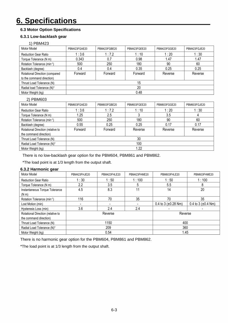
6. Specifications
6-3
6.3 Motor Option Specifications 6.3.1 Low-backlash gear
1) PBM423 Motor Model PBM423FGAE20 PBM423FGBE20 PBM423FGEE20 PBM423FGGE20 PBM423FGJE20 Reduction Gear Ratio 1 : 3.6 1 : 7.2 1 : 10 1 : 20 1 : 30 Torque Tolerance (N m) 0.343 0.7 0.98 1.47 1.47 Rotation Tolerance (min-1) 500 250 180 90 60 Backlash (degree) 0.4 0.4 0.35 0.25 0.25 Rotational Direction (compared to the command direction)
Forward Forward Forward Reverse Reverse
Thrust Load Tolerance (N) 15 Radial load Tolerance (N)* 20 Motor Weight (kg) 0.48
2) PBM603 Motor Model PBM603FGAE20 PBM603FGBE20 PBM603FGEE20 PBM603FGGE20 PBM603FGJE20 Reduction Gear Ratio 1 : 3.6 1 : 7.2 1 : 10 1 : 20 1 : 30 Torque Tolerance (N m) 1.25 2.5 3 3.5 4 Rotation Tolerance (min-1) 500 250 180 90 60 Backlash (degree) 0.55 0.25 0.25 0.17 0.17 Rotational Direction (relative to the command direction)
Forward Forward Reverse Reverse Reverse
Thrust Load Tolerance (N) 30 Radial Load Tolerance (N)* 100 Motor Weight (kg) 1.22
There is no low-backlash gear option for the PBM604, PBM861 and PBM862.
*The load point is at 1/3 length from the output shaft.
6.3.2 Harmonic gear Motor Model PBM423FHJE20 PBM423FHLE20 PBM423FHME20 PBM603FHLE20 PBM603FHME20 Reduction Gear Ratio 1 : 30 1 : 50 1 : 100 1 : 50 1 : 100 Torque Tolerance (N m) 2.2 3.5 5 5.5 8 Instantaneous Torque Tolerance (N m)
4.5 8.3 11 14 20
Rotation Tolerance (min-1) 116 70 35 70 35 Lost Motion (min) - - - 0.4 to 3 (±0.28 Nm) 0.4 to 3 (±0.4 Nm) Hysteresis Loss (min) 3.6 2.4 2.4 - - Rotational Direction (relative to the command direction)
Reverse Reverse
Thrust Load Tolerance (N) 1150 400 Radial Load Tolerance (N)* 209 360 Motor Weight (kg) 0.54 1.45
There is no harmonic gear option for the PBM604, PBM861 and PBM862.
*The load point is at 1/3 length from the output shaft.

6. Specifications
6-4
6.3.3 Holding brake
Motor model PBM423FCE20 PBM603FCE20 PBM604FCE20 Operation Method Non-excitation type Excitation Current (A) 0.08 0.25 0.25 Power Consumption (W) 2 6 6 Friction Torque (N m) 0.22 0.78 0.78 Brake Engage Time (ms) 20 Brake Release Time (ms) 30 Motor Weight (kg) 0.5 1.19 1.76
* The holding brake control function is built into the amplifier.
* There is no holding brake option for the PBM861 and PBM862.
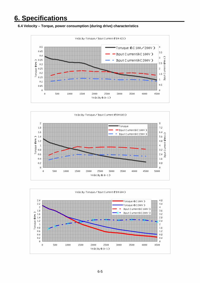
6. Specifications
6-5
6.4 Velocity – Torque, power consumption (during drive) characteristics
Velocity-Toruque/Input Current(PBM423)
0
0.05
0.1
0.15
0.2
0.25
0.3
0.35
0.4
0.45
0.5
0 500 1000 1500 2000 2500 3000 3500 4000 4500
Velocity(min-1)
Toruque(N・m)
0
0.5
1
1.5
2
2.5
3
3.5
4
Input Current(Arms)
Toruque(AC100/200V)
Input Current(AC100V)
Input Current(AC200V)
Velocity-Toruque/Input Current(PBM603)
0
0.2
0.4
0.6
0.8
1
1.2
1.4
1.6
1.8
2
0 500 1000 1500 2000 2500 3000 3500 4000 4500 5000
Velocity(min-1)
Toruque(N・m)
0
0.8
1.6
2.4
3.2
4
4.8
5.6
6.4
7.2
8
Input Current(Arms)
Toruque
Input Current(AC100V)
Input Current(AC230V)
Velocity-Toruque/Input Current(PBM604)
0
0.2
0.4
0.6
0.8
1
1.2
1.4
1.6
1.8
2
2.2
2.4
0 500 1000 1500 2000 2500 3000 3500 4000 4500
Velocity(min-1)
Toruque(N・m)
0
0.4
0.8
1.2
1.6
2
2.4
2.8
3.2
3.6
4
4.4
4.8Toruque(AC100V)
Toruque(AC200V)
Input Current(AC100V)
Input Current(AC200V)
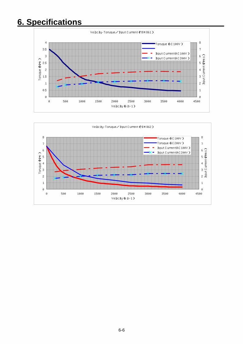
6. Specifications
6-6
Velocity-Toruque/Input Current(PBM861)
0
0.5
1
1.5
2
2.5
3
3.5
4
0 500 1000 1500 2000 2500 3000 3500 4000 4500
Velocity(min-1)
Toruque(N・m)
0
1
2
3
4
5
6
7
8
Input Current(Arms)
Toruque(AC100V)
Input Current(AC100V)
Input Current(AC200V)
Velocity-Toruque/Input Current(PBM862)
0
1
2
3
4
5
6
7
8
0 500 1000 1500 2000 2500 3000 3500 4000 4500
Velocity(min-1)
Toruque(N・m)
0
1
2
3
4
5
6
7
8
Input Current(Arms)
Toruque(AC100V)
Toruque(AC200V)
Input Current(AC100V)
Input Current(AC200V)
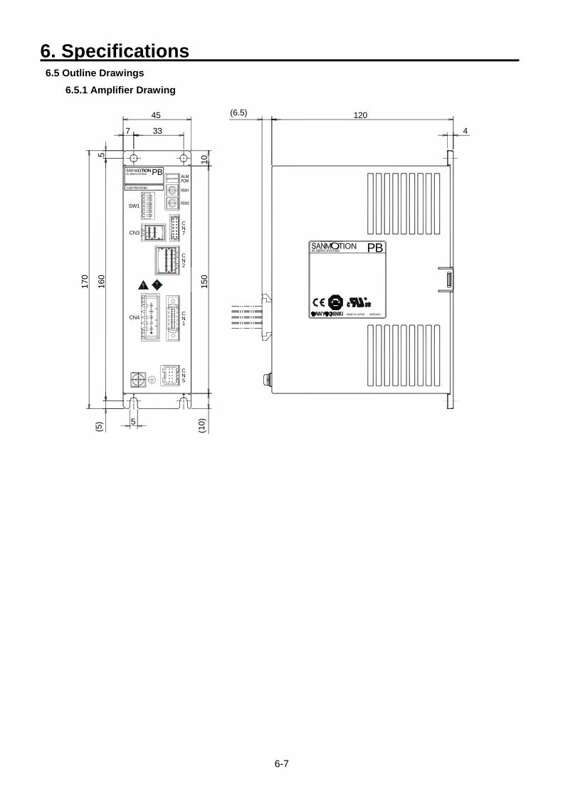
6. Specifications
6-7
6.5 Outline Drawings 6.5.1 Amplifier Drawing
5 4 3
SW1
CN4
CN3
5
(5)
170
160
(10)
150
NC
5
NC
1
98
7
NC
2
NC
7
0F
EDCBA
6 5 4 3 2
1
5
7
10
98
7
TION TIONM PB
45
33
0F
EDCBA
6 2
1
(6.5)
TIONM
00563491
PB
120
4
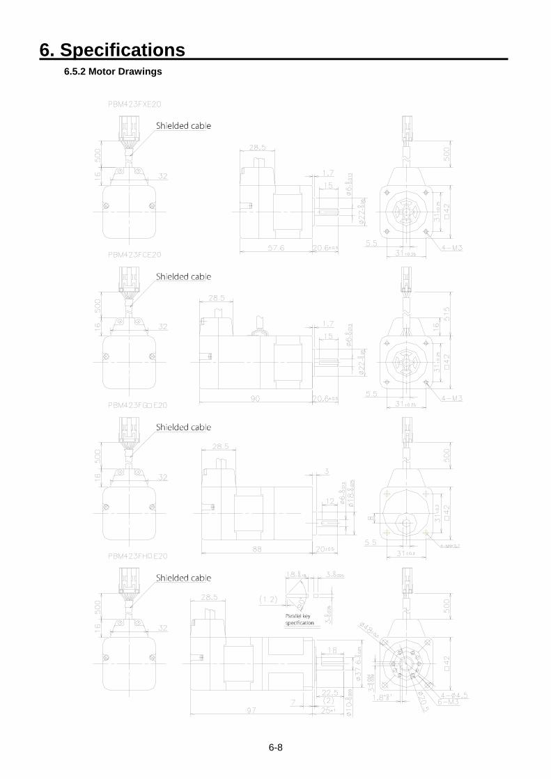
6. Specifications
6-8
6.5.2 Motor Drawings
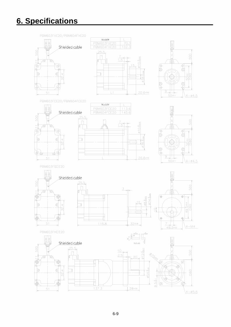
6. Specifications
6-9
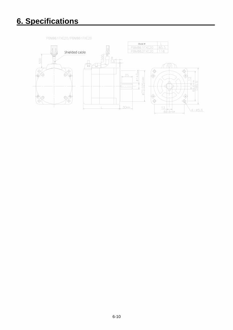
6. Specifications
6-10
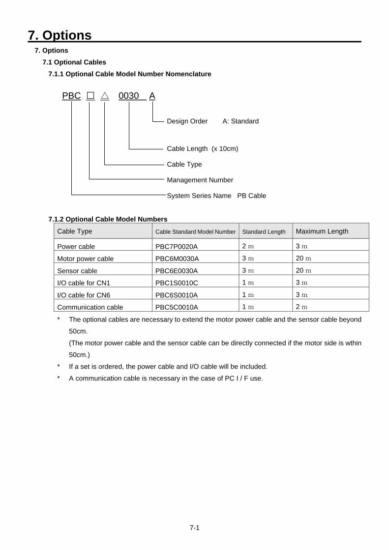
7. Options
7-1
7. Options 7.1 Optional Cables
7.1.1 Optional Cable Model Number Nomenclature PBC 0030 A
Design Order A: Standard
Cable Length (x 10cm)
Cable Type
Management Number
System Series Name PB Cable
7.1.2 Optional Cable Model Numbers
Cable Type Cable Standard Model Number Standard Length Maximum Length
Power cable PBC7P0020A 2 m 3 m
Motor power cable PBC6M0030A 3 m 20 m
Sensor cable PBC6E0030A 3 m 20 m
I/O cable for CN1 PBC1S0010C 1 m 3 m
I/O cable for CN6 PBC6S0010A 1 m 3 m
Communication cable PBC5C0010A 1 m 2 m
* The optional cables are necessary to extend the motor power cable and the sensor cable beyond
50cm.
(The motor power cable and the sensor cable can be directly connected if the motor side is wthin
50cm.)
* If a set is ordered, the power cable and I/O cable will be included.
* A communication cable is necessary in the case of PC I / F use.
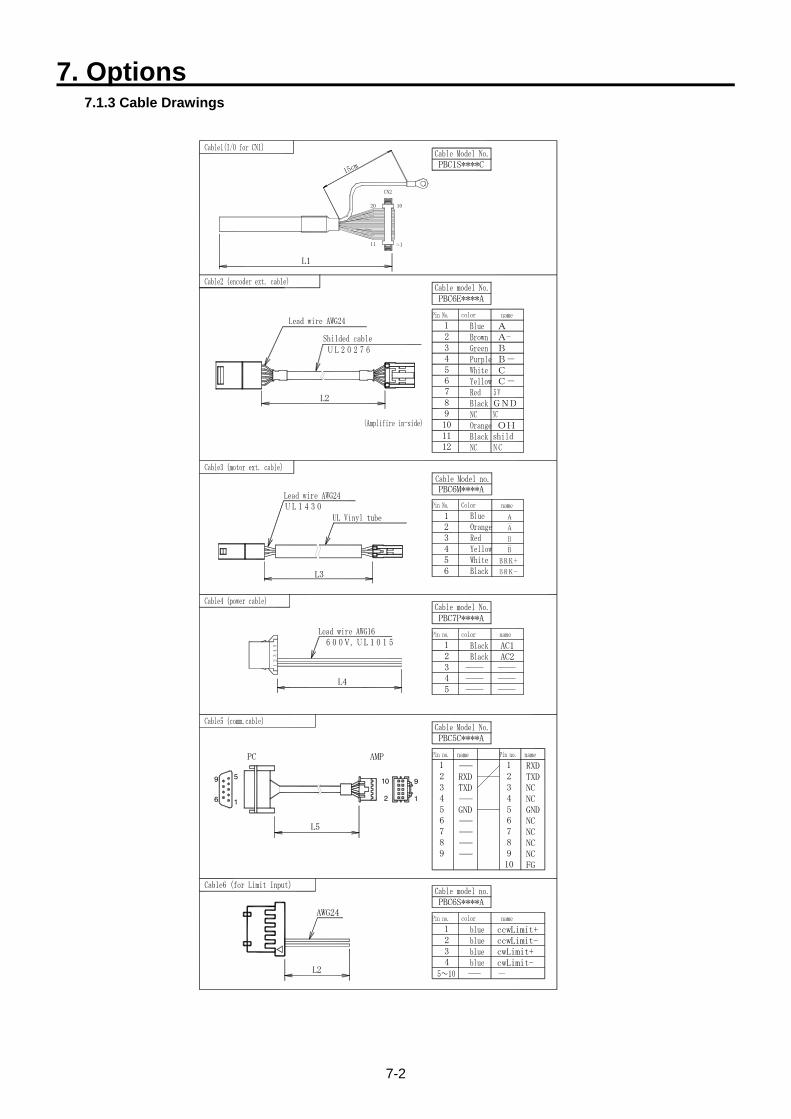
7. Options
7-2
7.1.3 Cable Drawings
PBC6M****A
L5
PC
1
5
6
9
AMP
2
10
42
13
5
L4
L3
12
43
67
98
10
5GND5
89
76
RXDTXD
PBC5C****A
1
934
21
GND
FG
NCNC
NCNC
NCNC
RXDTXD
AC2AC1
PBC7P****A
45
23
1
3
654
12
L2
L1
15cm
11 1
CN2
20 10
OH
C-CB-BA-A
6
1112
8910
7
PBC6E****A
1
3
54
2
PBC1S****C
AWG24
L2
PBC6S****A
2
43
1 ccwLimit+ccwLimit-cwLimit+cwLimit--
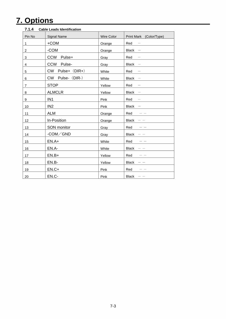
7. Options
7-3
7.1.4 Cable Leads Identification
Pin No Signal Name Wire Color Print Mark (Color/Type)
1 +COM Orange Red -
2 -COM Orange Black -
3 CCW Pulse+ Gray Red -
4 CCW Pulse- Gray Black -
5 CW Pulse+(DIR+) White Red -
6 CW Pulse-(DIR-) White Black -
7 STOP Yellow Red -
8 ALMCLR Yellow Black -
9 IN1 Pink Red -
10 IN2 Pink Black -
11 ALM Orange Red - -
12 In-Position Orange Black - -
13 SON monitor Gray Red - -
14 -COM/GND Gray Black - -
15 EN.A+ White Red - -
16 EN.A- White Black - -
17 EN.B+ Yellow Red - -
18 EN.B- Yellow Black - -
19 EN.C+ Pink Red - -
20 EN.C- Pink Black - -
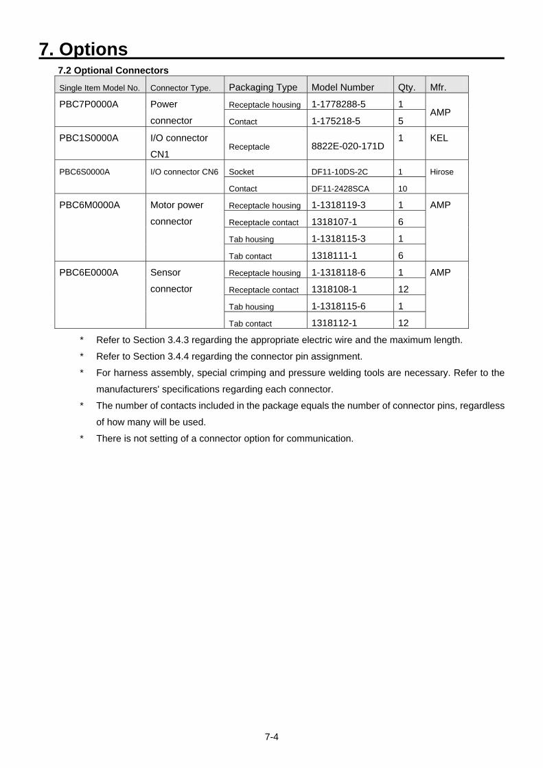
7. Options
7-4
7.2 Optional Connectors
Single Item Model No. Connector Type. Packaging Type Model Number Qty. Mfr.
Receptacle housing 1-1778288-5 1 PBC7P0000A
Power
connector Contact 1-175218-5 5 AMP
PBC1S0000A I/O connector
CN1 Receptacle 8822E-020-171D
1 KEL
Socket DF11-10DS-2C 1 PBC6S0000A I/O connector CN6
Contact DF11-2428SCA 10
Hirose
Receptacle housing 1-1318119-3 1
Receptacle contact 1318107-1 6
Tab housing 1-1318115-3 1
PBC6M0000A
Motor power
connector
Tab contact 1318111-1 6
AMP
Receptacle housing 1-1318118-6 1
Receptacle contact 1318108-1 12
Tab housing 1-1318115-6 1
PBC6E0000A Sensor
connector
Tab contact 1318112-1 12
AMP
* Refer to Section 3.4.3 regarding the appropriate electric wire and the maximum length.
* Refer to Section 3.4.4 regarding the connector pin assignment.
* For harness assembly, special crimping and pressure welding tools are necessary. Refer to the
manufacturers' specifications regarding each connector.
* The number of contacts included in the package equals the number of connector pins, regardless
of how many will be used.
* There is not setting of a connector option for communication.
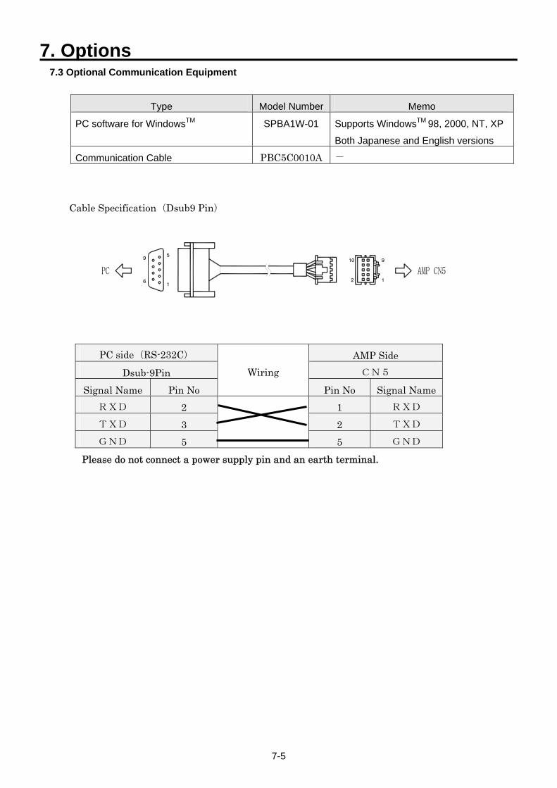
7. Options
7-5
7.3 Optional Communication Equipment
Type Model Number Memo
PC software for WindowsTM SPBA1W-01 Supports WindowsTM 98, 2000, NT, XP
Both Japanese and English versions
Communication Cable PBC5C0010A -
Cable Specification(Dsub9 Pin)
61
9 5
2 1
10 9
PC side(RS-232C) AMP Side Dsub-9Pin CN5
Signal Name Pin No
Wiring
Pin No Signal Name RXD 2 1 RXD TXD 3 2 TXD GND 5
5 GND
Please do not connect a power supply pin and an earth terminal.
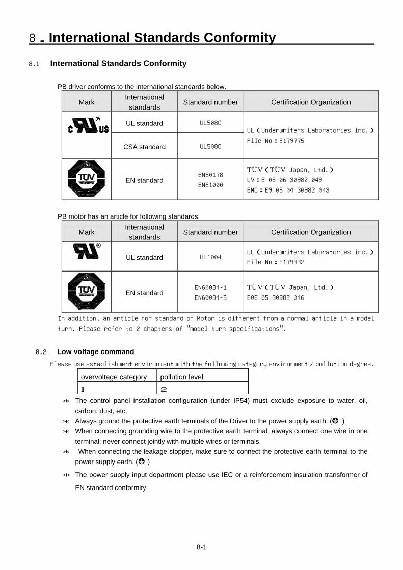
8.International Standards Conformity
8-1
8.1 International Standards Conformity
PB driver conforms to the international standards below.
Mark International standards
Standard number Certification Organization
UL standard UL508C
CSA standard UL508C
UL(Underwriters Laboratories inc.)
File No:E179775
EN standard EN50178
EN61000
TÜV(TÜV Japan, Ltd.) LV:B 05 06 30982 049
EMC:E9 05 04 30982 043
PB motor has an article for following standards.
Mark International standards
Standard number Certification Organization
UL standard UL1004 UL(Underwriters Laboratories inc.)
File No:E179832
EN standard EN60034-1
EN60034-5
TÜV(TÜV Japan, Ltd.) B05 05 30982 046
In addition, an article for standard of Motor is different from a normal article in a model
turn. Please refer to 2 chapters of "model turn specifications".
8.2 Low voltage command Please use establishment environment with the following category environment / pollution degree.
overvoltage category pollution level
Ⅱ 2
* The control panel installation configuration (under IP54) must exclude exposure to water, oil, carbon, dust, etc.
* Always ground the protective earth terminals of the Driver to the power supply earth. ( ) * When connecting grounding wire to the protective earth terminal, always connect one wire in one
terminal; never connect jointly with multiple wires or terminals. * When connecting the leakage stopper, make sure to connect the protective earth terminal to the
power supply earth. ( )
* The power supply input department please use IEC or a reinforcement insulation transformer of
EN standard conformity.
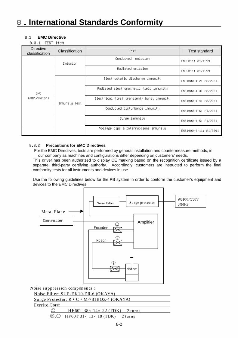
8.International Standards Conformity
8-2
8.3 EMC Directive 8.3.1 TEST Item
Directive classification Classification Test Test standard
Conducted emission
EN55011: A1/1999
Emission
Radiated emission
EN55011: A1/1999
Electrostatic discharge immunity
EN61000-4-2: A2/2001
Radiated electromagnetic field immunity
EN61000-4-3: A2/2001
Electrical first transient/ burst immunity
EN61000-4-4: A2/2001
Conducted disturbance immunity
EN61000-4-6: A1/2001
Surge immunity
EN61000-4-5: A1/2001
EMC
(AMP/Motor)
Immunity test
Voltage Dips & Interruptions immunity
EN61000-4-11: A1/2001
8.3.2 Precautions for EMC Directives
For the EMC Directives, tests are performed by general installation and countermeasure methods, in our company as machines and configurations differ depending on customers’ needs.
This driver has been authorized to display CE marking based on the recognition certificate issued by a separate, third-party certifying authority. Accordingly, customers are instructed to perform the final conformity tests for all instruments and devices in use.
Use the following guidelines below for the PB system in order to conform the customer’s equipment and devices to the EMC Directives.
Noise suppression components :
Amplifier
Motor
①Encoder
Controller
③
Metal Plane
Surge protectorNoise Filter
②Motor
AC100/230V
/50Hz
Noise Filter: SUP-EK10-ER-6 (OKAYA) Surge Protector: R・C・M-781BQZ-4 (OKAYA) Ferrite Core:
① HF60T 38×14×22 (TDK) 2 turns ②、③ HF60T 31×13×19 (TDK) 2 turns
ReleaseRevision A Mar.2007Revision B Oct.2007
*Remarks : Specifications Are Subject To Change Without Notice.
•Be sure to read the instruction manual before using this product.•Take sufficient safety measures and contact us before applying this product to medical equipment that may involve human lives.•Contact us before adapting this product for use with equipment that could cause serious social or public effects.•The use of this product in high motion environments where vibration is present, such as in vehicles or shipping vessels, is prohibited.•Do not convert or modify any equipment components.
CautionsCautions
Precautions For Adoption
The possibility of moderate or minor injuryand the occurrence of physical damage are assumed when the precautions at right column are not observed. Depending on the situation,this may cause serious consequences. Be sure to follow all listed precautions.
* Please contact our Business Division for questions and consultations regarding the above.
http://www.sanyodenki.com
Phone: +81 3 3917 2223
Phone: +49 6196 76113 0
Phone: +82 2 773 5623
Phone: +86 21 6235 1107
Phone: +1 310 783 5400
Phone: +33 1 48 63 26 61
Phone: +886 2 2511 3938
Phone: +852 2312 6250
Phone: +65 6223 1071
468 Amapola Avenue Torrance, CA 90501 U.S.A.
1-15-1, Kita-Otsuka, Toshima-ku, Tokyo 170-8451, Japan
P.A. Paris Nord II 48 Allee des Erables-VILLEPINTE BP.57286 F-95958 ROISSY CDG Cedex France
Frankfurter Strasse 63-69 65760 Eschborn Germany
10 Hoe Chiang Road #14-03A/04 Keppel Towers Singapore 089315
Room 2116, Bldg B, FAR EAST INTERNATIONAL PLAZA, No.317 XianXia Rd., Shanghai 200051 China
Room 1208,12F, No.96 Chung Shan N, Rd., Sec.2, Taipei 104, Taiwan, R.O.C.
Room 2305, 23/F, South Tower, Concordia Plaza, 1 Science Museum Rd., TST East, Kowloon, Hong Kong
9F 5-2, Sunwha-dong Jung-gu Seoul, 100-130, Korea