Embed Size (px)
Citation preview

INSTRUCTION MANUAL SUPPLEMENT MAGNETIC FLOWMETERS FXE4000 Series PMO Application
DE21-PMO & DE23-PMO
PN25118

7.1
FXE4000 Instruction Manual Supplement for PMO Application
Instructions for Installation of DE21-PMO with E4-PMO and DE23-PMO Magnetic Flowmeters in PMO Applications
For all PMO applications, these instructions supersede the operating instructions where applicable. 1) Installation
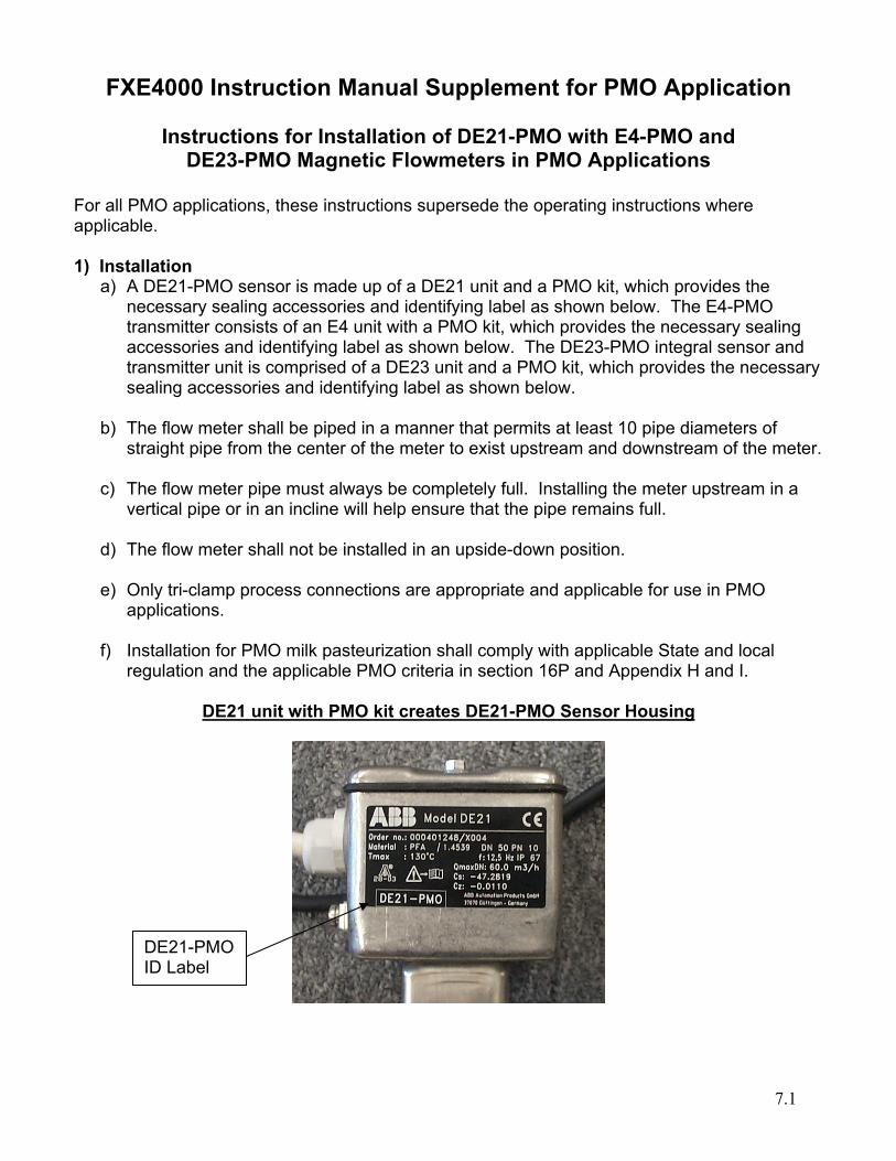
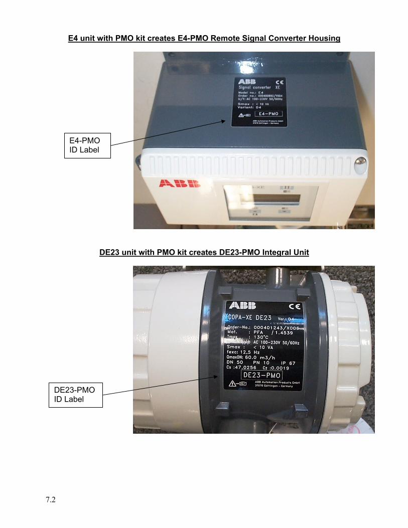
a) A DE21-PMO sensor is made up of a DE21 unit and a PMO kit, which provides the necessary sealing accessories and identifying label as shown below. The E4-PMO transmitter consists of an E4 unit with a PMO kit, which provides the necessary sealing accessories and identifying label as shown below. The DE23-PMO integral sensor and transmitter unit is comprised of a DE23 unit and a PMO kit, which provides the necessary sealing accessories and identifying label as shown below.
b) The flow meter shall be piped in a manner that permits at least 10 pipe diameters of
straight pipe from the center of the meter to exist upstream and downstream of the meter. c) The flow meter pipe must always be completely full. Installing the meter upstream in a
vertical pipe or in an incline will help ensure that the pipe remains full. d) The flow meter shall not be installed in an upside-down position. e) Only tri-clamp process connections are appropriate and applicable for use in PMO
applications. f) Installation for PMO milk pasteurization shall comply with applicable State and local
regulation and the applicable PMO criteria in section 16P and Appendix H and I.
DE21 unit with PMO kit creates DE21-PMO Sensor Housing
DE21-PMO ID Label
7.2
E4 unit with PMO kit creates E4-PMO Remote Signal Converter Housing
DE23 unit with PMO kit creates DE23-PMO Integral Unit
E4-PMO ID Label
DE23-PMO ID Label
7.3
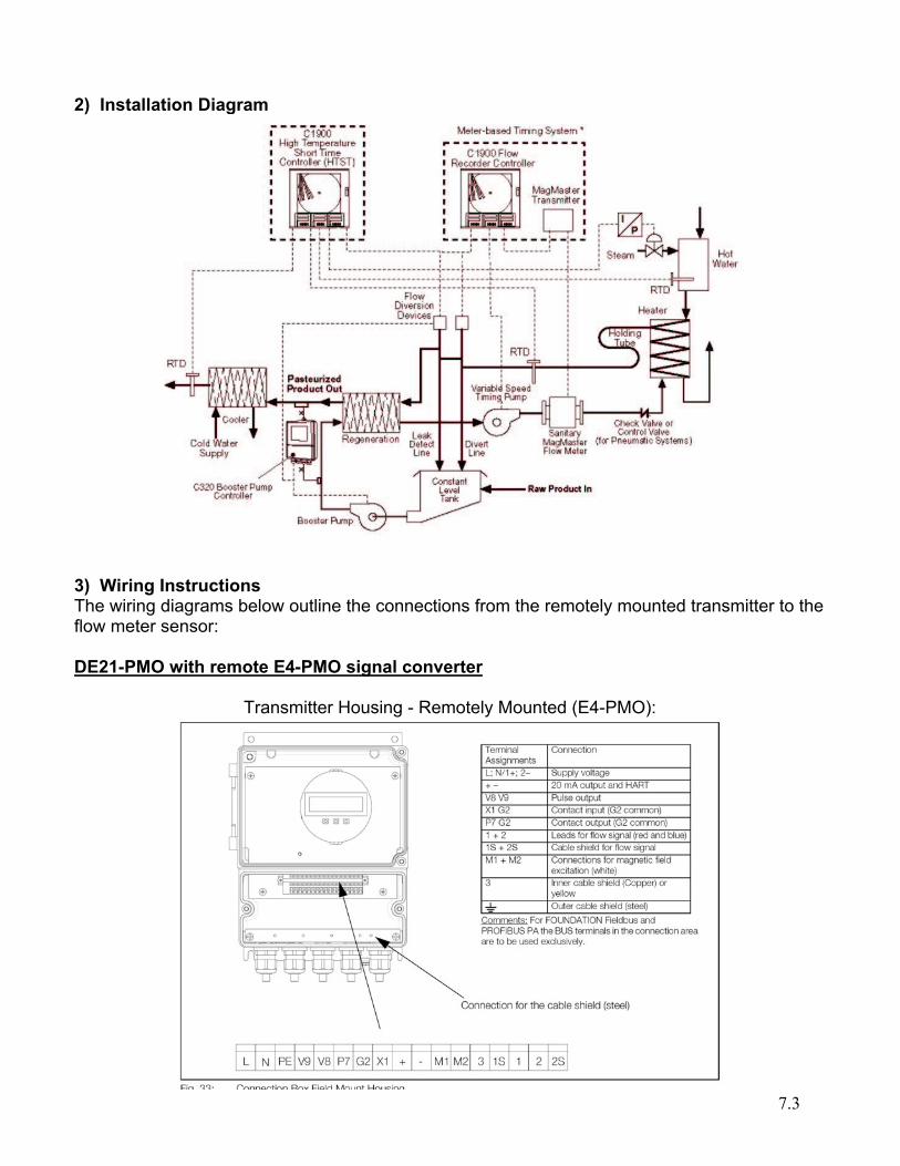
2) Installation Diagram
3) Wiring Instructions The wiring diagrams below outline the connections from the remotely mounted transmitter to the flow meter sensor: DE21-PMO with remote E4-PMO signal converter
Transmitter Housing - Remotely Mounted (E4-PMO):
7.4
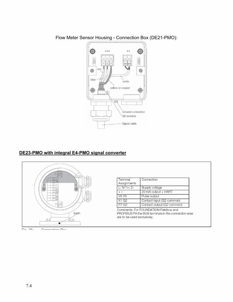
Flow Meter Sensor Housing - Connection Box (DE21-PMO):
DE23-PMO with integral E4-PMO signal converter
7.5
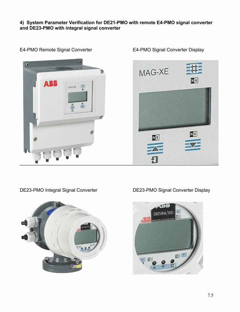
4) System Parameter Verification for DE21-PMO with remote E4-PMO signal converter and DE23-PMO with integral signal converter E4-PMO Remote Signal Converter E4-PMO Signal Converter Display
DE23-PMO Integral Signal Converter DE23-PMO Signal Converter Display
7.6
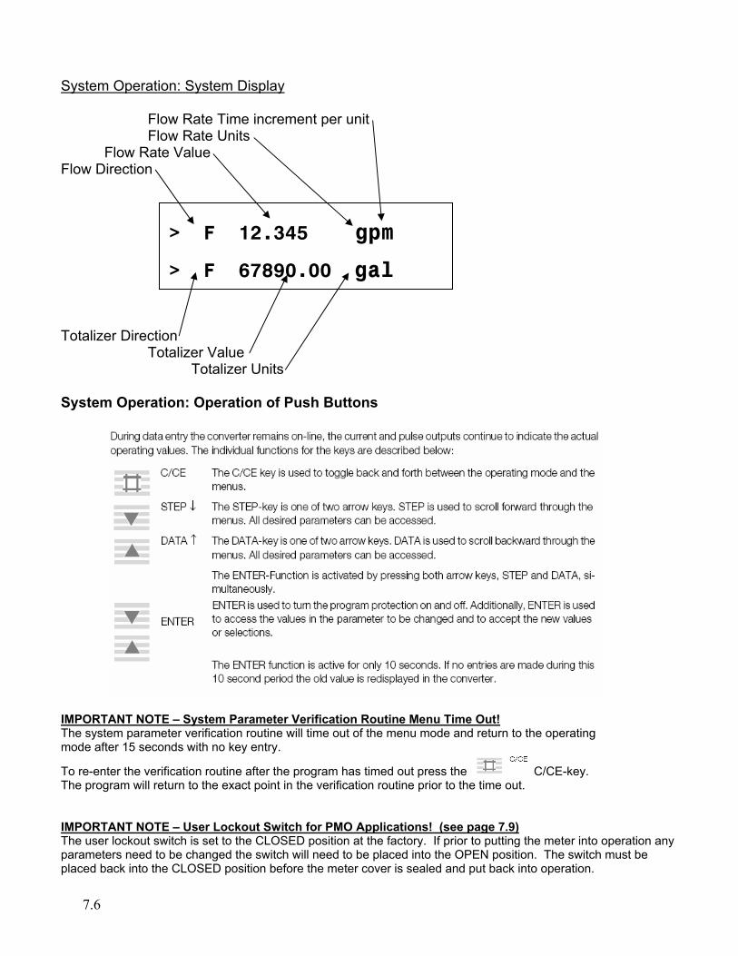
System Operation: System Display
Flow Rate Time increment per unit Flow Rate Units
Flow Rate Value Flow Direction Totalizer Direction
Totalizer Value Totalizer Units
System Operation: Operation of Push Buttons
IMPORTANT NOTE – System Parameter Verification Routine Menu Time Out! The system parameter verification routine will time out of the menu mode and return to the operating mode after 15 seconds with no key entry.
To re-enter the verification routine after the program has timed out press the C/CE-key. The program will return to the exact point in the verification routine prior to the time out. IMPORTANT NOTE – User Lockout Switch for PMO Applications! (see page 7.9) The user lockout switch is set to the CLOSED position at the factory. If prior to putting the meter into operation any parameters need to be changed the switch will need to be placed into the OPEN position. The switch must be placed back into the CLOSED position before the meter cover is sealed and put back into operation.
> F 12.345 gpm
> F 67890.00 gal
7.7
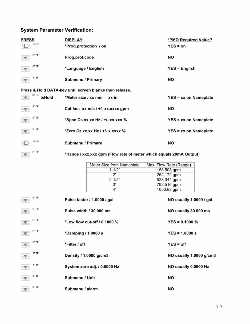
System Parameter Verification: PRESS DISPLAY *PMO Required Value?
*Prog.protection / on YES = on
Prog.prot.code NO
*Language / English YES = English
Submenu / Primary NO Press & Hold DATA-key until screen blanks then release.
&Hold *Meter size / xx mm xx in YES = xx on Nameplate
Cal-fact xx m/s / +/- xx.xxxx gpm NO
*Span Cs xx.xx Hz / +/- xx.xxx % YES = xx on Nameplate
*Zero Cz xx.xx Hz / +/- x.xxxx % YES = xx on Nameplate
Submenu / Primary NO
*Range / xxx.xxx gpm (Flow rate of meter which equals 20mA Output)
Meter Size from Nameplate Max. Flow Rate (Range) 1-1/2” 158.503 gpm
2” 264.172 gpm 2-1/2” 528.344 gpm
3” 792.516 gpm 4” 1056.68 gpm
Pulse factor / 1.0000 / gal NO usually 1.0000 / gal
Pulse width / 30.000 ms NO usually 30.000 ms
*Low flow cut-off / 0.1000 % YES = 0.1000 %
*Damping / 1.0000 s YES = 1.0000 s
*Filter / off YES = off
Density / 1.0000 g/cm3 NO usually 1.0000 g/cm3
System zero adj. / 0.0000 Hz NO usually 0.0000 Hz
Submenu / Unit NO
Submenu / alarm NO
7.8
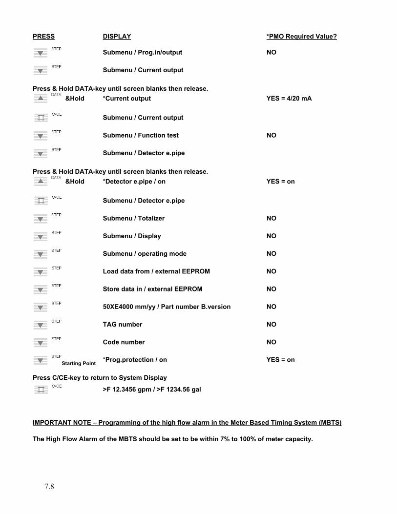
PRESS DISPLAY *PMO Required Value?
Submenu / Prog.in/output NO
Submenu / Current output Press & Hold DATA-key until screen blanks then release.
&Hold *Current output YES = 4/20 mA
Submenu / Current output
Submenu / Function test NO
Submenu / Detector e.pipe Press & Hold DATA-key until screen blanks then release.
&Hold *Detector e.pipe / on YES = on
Submenu / Detector e.pipe
Submenu / Totalizer NO
Submenu / Display NO
Submenu / operating mode NO
Load data from / external EEPROM NO
Store data in / external EEPROM NO
50XE4000 mm/yy / Part number B.version NO
TAG number NO
Code number NO
Starting Point *Prog.protection / on YES = on Press C/CE-key to return to System Display
>F 12.3456 gpm / >F 1234.56 gal IMPORTANT NOTE – Programming of the high flow alarm in the Meter Based Timing System (MBTS) The High Flow Alarm of the MBTS should be set to be within 7% to 100% of meter capacity.
7.9
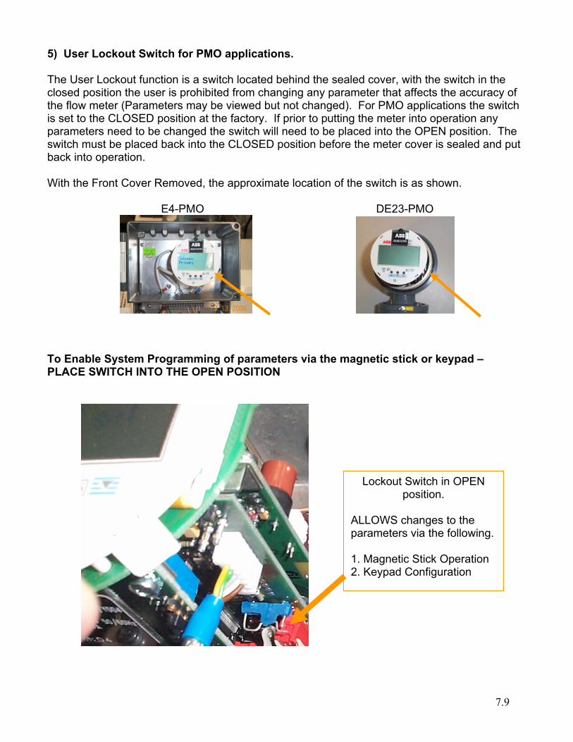
5) User Lockout Switch for PMO applications. The User Lockout function is a switch located behind the sealed cover, with the switch in the closed position the user is prohibited from changing any parameter that affects the accuracy of the flow meter (Parameters may be viewed but not changed). For PMO applications the switch is set to the CLOSED position at the factory. If prior to putting the meter into operation any parameters need to be changed the switch will need to be placed into the OPEN position. The switch must be placed back into the CLOSED position before the meter cover is sealed and put back into operation. With the Front Cover Removed, the approximate location of the switch is as shown. E4-PMO DE23-PMO
To Enable System Programming of parameters via the magnetic stick or keypad – PLACE SWITCH INTO THE OPEN POSITION
Lockout Switch in OPEN position.
ALLOWS changes to the parameters via the following. 1. Magnetic Stick Operation 2. Keypad Configuration
7.10
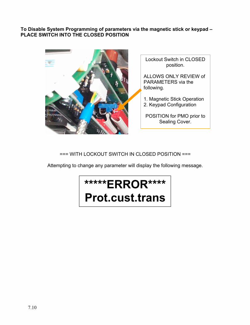
To Disable System Programming of parameters via the magnetic stick or keypad – PLACE SWITCH INTO THE CLOSED POSITION
=== WITH LOCKOUT SWITCH IN CLOSED POSITION ===
Attempting to change any parameter will display the following message.
*****ERROR****Prot.cust.trans
Lockout Switch in CLOSED position.
ALLOWS ONLY REVIEW of PARAMETERS via the following. 1. Magnetic Stick Operation 2. Keypad Configuration POSITION for PMO prior to
Sealing Cover.
7.11
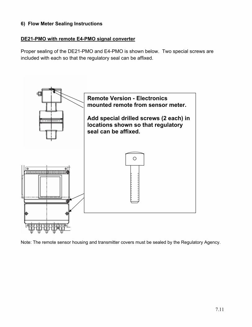
6) Flow Meter Sealing Instructions DE21-PMO with remote E4-PMO signal converter Proper sealing of the DE21-PMO and E4-PMO is shown below. Two special screws are included with each so that the regulatory seal can be affixed.
Note: The remote sensor housing and transmitter covers must be sealed by the Regulatory Agency.
Remote Version - Electronics mounted remote from sensor meter. Add special drilled screws (2 each) in locations shown so that regulatory seal can be affixed.
7.12
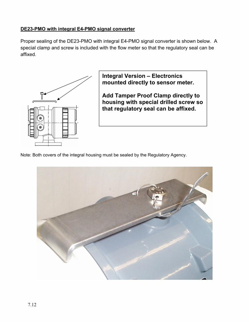
DE23-PMO with integral E4-PMO signal converter Proper sealing of the DE23-PMO with integral E4-PMO signal converter is shown below. A special clamp and screw is included with the flow meter so that the regulatory seal can be affixed.
Note: Both covers of the integral housing must be sealed by the Regulatory Agency.
Integral Version – Electronics mounted directly to sensor meter. Add Tamper Proof Clamp directly to housing with special drilled screw so that regulatory seal can be affixed.

UK ABB Limited Oldends Lane, Stonehouse Gloucestershire, GL 10 3TA UK Tel: +44 (0)1480 475321 Fax: +44 (0)1480 217948
USA ABB Inc. 125 East County Line Road Warminster, PA 18974-4995 USA Tel: +1 215 674 6000 Fax: +1 215 674 7183
ABB (www.abb.com) is a leader in power and automation technologies that enable utility and industry customers to improve performance while lowering environmental impact. The ABB Group of companies operates in around 100 countries and employs about 105,000 people. www.abb.com/instrumentation
The Company’s policy is one of continuous product improvement and the right is reserved to modify the
information contained herein without notice.
Printed in USA (7/06) © ABB 2006
PN25
118_
0