Embed Size (px)
Citation preview
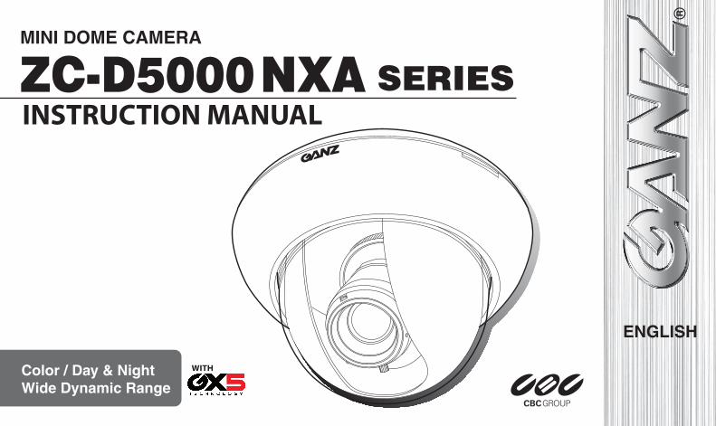
INSTRUCTION MANUAL
WITH
EG-2
Thank you for your purchase of this product. Before operating this product, please read this instruction manual carefully. After you have read this manual, store it in a safe place for future reference.
CONTENTSPRODUCT FEATURES .................................................................................... EG-2SAFETY PRECAUTIONS ................................................................................. EG-3PART NAMES ................................................................................................... EG-4INSTALLATION AND ADJUSTMENT .............................................................. EG-5MODEL DESCRIPTION ................................................................................. EG-10SPECIFICATIONS .......................................................................................... EG-11
PRODUCT FEATURES• High-resolution surveillance camera with a new built-in 1/3-type CCD. It delivers
clear images at a horizontal resolution of 700 TVL by using a new high-resolu-tion CCD and image processing technology.
• Integrated varifocal lens allows for versatile application and easy installation.• Surface or embedded installation.• Manual pan/tilt/rotation mechanism.• 12 V DC/24 V AC auto switching power supply.• The new 12,600 times Wide Dynamic Range (WDR) processing allows sharp
images even if the pictures are shot in mixed indoor/outdoor scenes with back-light.
• New Easy Focus function helps adjust the lens focus by edge enhancement, focus level bar, and screen view zoom-up / down.
• The Color Bar Output function enables the checking and adjustment of cable signal levels and monitoring of the image quality.
• The Defog function provides high-quality images with automatically enhanced contrast in an environment with poor visibility, such as fog, mist, rain, and snow.
• The 3D-Digital Noise Reduction (3D-DNR) function realizes low noise and high sensitivity.
• The OSD settings can be dynamically switched using the Profile Switching func-tion. With these functions, two preset profiles can be switched with each other when a Mode Selection terminal has been controlled or Day/Night switching has been made. A combination of profiles can be selected according to surveillance conditions.
• Day/Night function provides a high-sensitivity black and white image in low light conditions (e.g., night time) by automatically switching the camera to black and white mode. The camera is automatically switched to color mode in brighter light conditions (e.g., day time).
• This product offers additional functions such as Stabilizer, Privacy Mask, and Motion Detection functions.
EG-3
SAFETY PRECAUTIONSThe installation should be made by a qualified service person and should conform to all local codes. For this device provided no power switch, the installation shall be carried out in accordance with the rules of the country or the region in which the equipment is to be installed.
This symbol indicates that there is a possibility of death or damage to operator or others.
(1) Use only 24V AC power supply marked class 2 or +12V DC regulated power supply marked class 2.
(2) To prevent fire or electrical shock, UL listed class 2 wiring should be used for the 12V DC or 24V AC input terminal.
(3) Be sure to connect each lead to the appropriate terminal. Wrong connection may cause malfunction and/or damage to the video camera.
(4) Never attempt to disassemble or modify the camera.(5) If an abnormality should occur, immediately turn off the power and consult your
dealer.(6) To prevent fire or electric shock, do not expose this product to rain or moisture.
This symbol indicates that there is a possibility of injury or damage to equip-ment.
(1) Do not attempt to aim the camera at the sun or other extremely bright objects that cause smear to appear irrespective of whether the camera is operating or not. This can damage the CCD (Charge Coupled Device).
(2) Do not place the camera in the following locations. 1 Locations subject to extremely high or low temperatures. (Operating temperature range: -10°C to +50°C {14°F to 122°F}) (Storage temperature range: -20°C to +60°C {-4°F to 140°F})2 Locations subject to high levels of humidity and dust. (Operating humidity range: max 85% {No condensation}) (Storage humidity range: max 95% {No condensation})3 Locations where there are large amounts of water vapor and steam.
(3) Ensure the location selected is sufficiently strong enough to support the weight of the camera and is free from vibration.
(4) When this camera is installed near equipment that emits a strong electromag-netic field, some irregularity such as noise on the monitor screen may happen.
(5) Do not allow the camera to be subjected to strong impacts or shocks. The camera could be damaged by improper handling or storage.
This device complies with Part 15 of the FCC Rules. Operation is subject to following two conditions: (1) This device may not cause harmful interference. (2) This device must accept any interference received, including interference
that may cause undesired operation.
Industry Canada’s Compliance StatementThis Class A digital apparatus complies with Canadian ICES-003.Cet appareil numérique de la classe A est conforme à la norme NMB-003 du Canada.
EG-4
PART NAMES
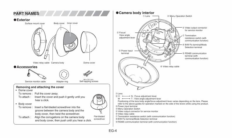
ExteriorBody cover Inner coverSurface mount cover
Camera body Dome cover Video relay cable
Accessories
Service monitor cable Adapter ringM4 x 20 2 pcs.
Self-tapping screws
Removing and attaching the cover• Dome cover
To remove : Pull the cover away.To attach : Insert the cover and push it gently until you
hear a click.• Body cover
To remove : Insert a flat-bladed screwdriver into the groove between the camera body and the body cover, then twist the screwdriver.
To attach : Align the corrugations on the camera body and body cover, then push until you hear a click.
Flat-bladed screwdriver
Camera body interior1 Lens 4 Menu Operation Switch
2 Focus/View angle adjustment lever
5 Video output connector for service monitor
7 Termination resistance switch (with communication function)
8 B/W Fix terminal/Mode Selection terminal
9 RS485 communication terminal (with communication function)
6 Video relay cable
3 Power input terminal
1Lens2∞ N : Focus adjustment lever
W T : View angle adjustment leverPositioning of the lens body angle/focus adjustment lever varies depending on the lens. Please refer to the above guides for operation marked on the side of the levers while using the product.
3Power input terminal4 Menu Operation Switch5 Video output connector for service monitor6 Video relay cable7 Termination resistance switch (with communication function)8 B/W Fix terminal/Mode Selection terminal9 RS485 communication terminal (with communication function)
EG-5
INSTALLATION AND ADJUSTMENT
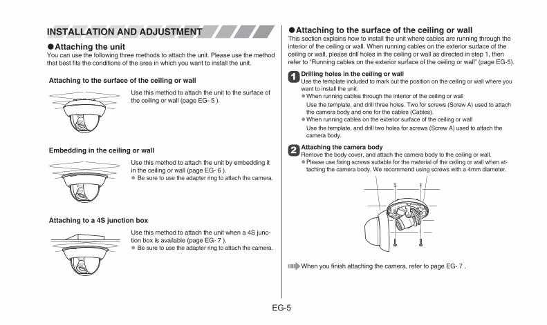
Attaching the unitYou can use the following three methods to attach the unit. Please use the method that best fits the conditions of the area in which you want to install the unit.
Attaching to the surface of the ceiling or wall
Use this method to attach the unit to the surface of the ceiling or wall (page EG- 5 ).
Embedding in the ceiling or wall
Use this method to attach the unit by embedding it in the ceiling or wall (page EG- 6 ). Be sure to use the adapter ring to attach the camera.
Attaching to a 4S junction box
Use this method to attach the unit when a 4S junc-tion box is available (page EG- 7 ). Be sure to use the adapter ring to attach the camera.
Attaching to the surface of the ceiling or wallThis section explains how to install the unit where cables are running through the interior of the ceiling or wall. When running cables on the exterior surface of the ceiling or wall, please drill holes in the ceiling or wall as directed in step 1, then refer to “Running cables on the exterior surface of the ceiling or wall” (page EG-5).
1 Drilling holes in the ceiling or wallUse the template included to mark out the position on the ceiling or wall where you want to install the unit. When running cables through the interior of the ceiling or wall
Use the template, and drill three holes. Two for screws (Screw A) used to attach the camera body and one for the cables (Cables). When running cables on the exterior surface of the ceiling or wall
Use the template, and drill two holes for screws (Screw A) used to attach the camera body.
2 Attaching the camera bodyRemove the body cover, and attach the camera body to the ceiling or wall. Please use fixing screws suitable for the material of the ceiling or wall when at-
taching the camera body. We recommend using screws with a 4mm diameter.
When you finish attaching the camera, refer to page EG- 7 .
EG-6
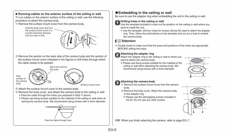
Running cables on the exterior surface of the ceiling or wallTo run cables on the exterior surface of the ceiling or wall, use the following procedure to attach the camera body.1 Remove the surface mount cover from the camera body.
Hold the body cover and turn the surface mount cover in a counter-clockwise direction until you hear a click.
2 Remove the section on the back side of the camera body and the section of the surface mount cover indicated in the figures to drill holes through which the cable needs to be passed.
Rear surface of the camera body Surface mount cover
Bend and remove this area.
3 Attach the surface mount cover to the camera body.4 Remove the body cover, and attach the camera body to the ceiling or wall. Pass the cable through the holes you prepared in Step 2 above. Please use fixing screws suitable for the material of the ceiling or wall when at-
taching the camera body. We recommend using screws with a 4mm diameter.
Pass the cable through here.
Embedding in the ceiling or wallBe sure to use the adapter ring when embedding the unit in the ceiling or wall.
1 Drilling holes in the ceiling or wallUse the template included to mark out the position on the ceiling or wall where you want to install the unit. Use the template, drill two holes for screws (Screw B) used to attach the adapter
ring. Then, follow the perforations on the template and cut out a hole to embed the camera body.
Double check to make sure that the sizes and positions of the holes are appropriate BEFORE drilling the holes.
2 Attaching the adapter ringAttach the adapter ring to the ceiling or wall to which you want to attach the camera body. Please use fixing screws suitable for the material of the
ceiling or wall when attaching the camera body. We recommend using screws with a 4mm diameter.
3 Attaching the camera body1 Remove the surface mount cover from the camera
body.2 Remove the body cover, Attach the camera body
to the adapter ring. Please use the self-tapping screws included in
the kit. Do not use any other screws.
When you finish attaching the camera, refer to page EG- 7 .
EG-7
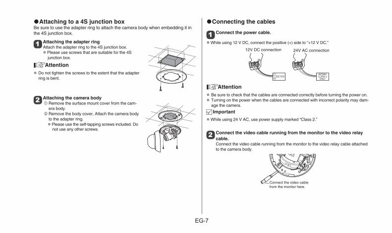
Attaching to a 4S junction boxBe sure to use the adapter ring to attach the camera body when embedding it in the 4S junction box.
1 Attaching the adapter ringAttach the adapter ring to the 4S junction box. Please use screws that are suitable for the 4S
junction box.
Do not tighten the screws to the extent that the adapter ring is bent.
2 Attaching the camera body1 Remove the surface mount cover from the cam-
era body.2 Remove the body cover, Attach the camera body
to the adapter ring. Please use the self-tapping screws included. Do
not use any other screws.
Connecting the cables
1 Connect the power cable.
While using 12 V DC, connect the positive (+) side to “+12 V DC.”
12V DC connection 24V AC connection
Be sure to check that the cables are connected correctly before turning the power on. Turning on the power when the cables are connected with incorrect polarity may dam-
age the camera.
While using 24 V AC, use power supply marked “Class 2.”
2 Connect the video cable running from the monitor to the video relay cable.Connect the video cable running from the monitor to the video relay cable attached to the camera body.
Connect the video cable from the monitor here.
EG-8
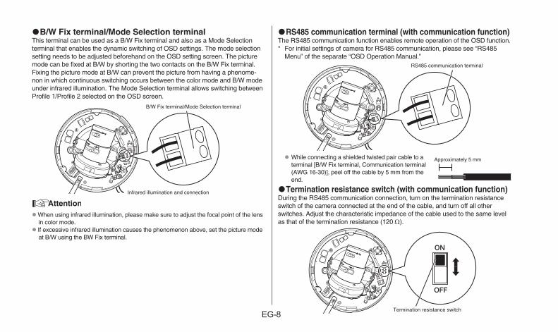
B/W Fix terminal/Mode Selection terminalThis terminal can be used as a B/W Fix terminal and also as a Mode Selection terminal that enables the dynamic switching of OSD settings. The mode selection setting needs to be adjusted beforehand on the OSD setting screen. The picture mode can be fixed at B/W by shorting the two contacts on the B/W Fix terminal. Fixing the picture mode at B/W can prevent the picture from having a phenome-non in which continuous switching occurs between the color mode and B/W mode under infrared illumination. The Mode Selection terminal allows switching between Profile 1/Profile 2 selected on the OSD screen.
B/W Fix terminal/Mode Selection terminal
Infrared illumination and connection
When using infrared illumination, please make sure to adjust the focal point of the lens in color mode.
If excessive infrared illumination causes the phenomenon above, set the picture mode at B/W using the BW Fix terminal.
RS485 communication terminal (with communication function)The RS485 communication function enables remote operation of the OSD function.* For initial settings of camera for RS485 communication, please see “RS485
Menu” of the separate “OSD Operation Manual.”RS485 communication terminal
While connecting a shielded twisted pair cable to a terminal [B/W Fix terminal, Communication terminal (AWG 16-30)], peel off the cable by 5 mm from the end.
Termination resistance switch (with communication function)During the RS485 communication connection, turn on the termination resistance switch of the camera connected at the end of the cable, and turn off all other switches. Adjust the characteristic impedance of the cable used to the same level as that of the termination resistance (120 Ω).
Termination resistance switch
Approximately 5 mm
EG-9
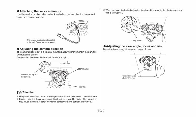
Attaching the service monitorUse the service monitor cable to check and adjust camera direction, focus, and angle on a service monitor.
The service monitor is not supplied in the cell. Please have one ready.
Adjusting the camera directionThe camera body is set in a tri-axial mounting allowing movement in the pan, tilt, and rotational planes. 1 Adjust the direction of the lens so it faces the subject.
350° Pan
350° Rotation
180° Tilt
Indicates the top of the camera.
Using the camera in a near-horizontal position will show the camera cover on screen. Forcibly adjusting the camera to point in directions beyond the limits of the mounting
may cause the cable to catch on internal components and damage the camera.
2 When you have finished adjusting the direction of the lens, tighten the locking screw with a screwdriver.
Locking screw
Adjusting the view angle, focus and irisMove the lever to adjust focus and angle of view.
Focus/View angle adjustment lever
EG-10
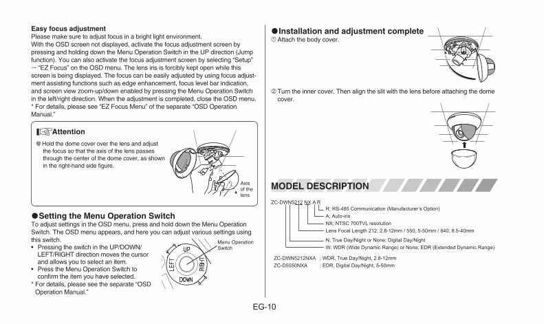
Easy focus adjustmentPlease make sure to adjust focus in a bright light environment.With the OSD screen not displayed, activate the focus adjustment screen by pressing and holding down the Menu Operation Switch in the UP direction (Jump function). You can also activate the focus adjustment screen by selecting “Setup” “EZ Focus” on the OSD menu. The lens iris is forcibly kept open while this screen is being displayed. The focus can be easily adjusted by using focus adjust-ment assisting functions such as edge enhancement, focus level bar indication, and screen view zoom-up/down enabled by pressing the Menu Operation Switch in the left/right direction. When the adjustment is completed, close the OSD menu.* For details, please see “EZ Focus Menu” of the separate “OSD Operation Manual.”
Hold the dome cover over the lens and adjust the focus so that the axis of the lens passes through the center of the dome cover, as shown in the right-hand side figure.
Axis of the lens
Setting the Menu Operation SwitchTo adjust settings in the OSD menu, press and hold down the Menu Operation Switch. The OSD menu appears, and here you can adjust various settings using this switch.• Pressing the switch in the UP/DOWN/
LEFT/RIGHT direction moves the cursor and allows you to select an item.
• Press the Menu Operation Switch to confirm the item you have selected.
* For details, please see the separate “OSD Operation Manual.”
Installation and adjustment complete1Attach the body cover.
2 Turn the inner cover. Then align the slit with the lens before attaching the dome cover.
MODEL DESCRIPTION
R; RS-485 Communication (Manufacturer’s Option)A; Auto-irisNX; NTSC 700TVL resolutionLens Focal Length 212; 2.8-12mm / 550; 5-50mm / 840; 8.5-40mm
N; True Day/Night or None; Digital Day/NightW; WDR (Wide Dynamic Range) or None; EDR (Extended Dynamic Range)
ZC-DWN5212NXA ; WDR, True Day/Night, 2.8-12mmZC-D5550NXA ; EDR, Digital Day/Night, 5-50mm
ZC-DWN5212 NX A R
Menu Operation Switch
EG-11
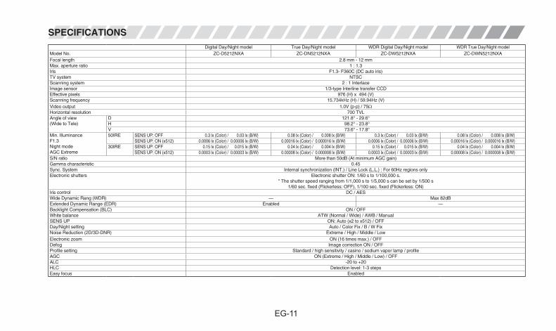
SPECIFICATIONSDigital Day/Night model True Day/Night model WDR Digital Day/Night model WDR True Day/Night model
Model No. ZC-D5212NXA ZC-DN5212NXA ZC-DW5212NXA ZC-DWN5212NXAFocal length 2.8 mm - 12 mmMax. aperture ratio 1 : 1.3Iris F1.3- F360C (DC auto iris)TV system NTSCScanning system 2 : 1 InterlaceImage sensor 1/3-type Interline transfer CCDEffective pixels 976 (H) x 494 (V)Scanning frequency 15.734kHz (H) / 59.94Hz (V)Video output 1.0V (p-p) / 75ΩHorizontal resolution 700 TVLAngle of view(Wide to Tele)
D 121.8° - 29.6°H 98.2° - 23.8°V 73.6° - 17.8°
Min. IlluminanceF1.3Night modeAGC Extreme
50IRE SENS UP: OFF 0.3 lx (Color) / 0.03 lx (B/W) 0.08 lx (Color) / 0.008 lx (B/W) 0.3 lx (Color) / 0.03 lx (B/W) 0.08 lx (Color) / 0.008 lx (B/W)SENS UP: ON (x512) 0.0006 lx (Color) / 0.00006 lx (B/W) 0.00016 lx (Color) / 0.000016 lx (B/W) 0.0006 lx (Color) / 0.00006 lx (B/W) 0.00016 lx (Color) / 0.000016 lx (B/W)
30IRE SENS UP: OFF 0.15 lx (Color) / 0.015 lx (B/W) 0.04 lx (Color) / 0.004 lx (B/W) 0.15 lx (Color) / 0.015 lx (B/W) 0.04 lx (Color) / 0.004 lx (B/W)SENS UP: ON (x512) 0.0003 lx (Color) / 0.00003 lx (B/W) 0.00008 lx (Color) / 0.000008 lx (B/W) 0.0003 lx (Color) / 0.00003 lx (B/W) 0.00008 lx (Color) / 0.000008 lx (B/W)
S/N ratio More than 50dB (At minimum AGC gain)Gamma characteristic 0.45Sync. System Internal synchronization (INT.) / Line Lock (L.L.) : For 60Hz regions onlyElectronic shutters Electronic shutter ON: 1/60 s to 1/100,000 s.
* The shutter speed ranging from 1/1,000 s to 1/5,000 s can be set by 1/500 s1/60 sec. fixed (Flickerless: OFF), 1/100 sec. fixed (Flickerless: ON)
Iris control DC / AESWide Dynamic Rang (WDR) — Max 82dBExtended Dynamic Range (EDR) Enabled —Backlight Compensation (BLC) ON / OFFWhite balance ATW (Normal / Wide) / AWB / ManualSENS UP ON: Auto (x2 to x512) / OFFDay/Night setting Auto / Color Fix / B / W FixNoise Reduction (2D/3D-DNR) Extreme / High / Middle / LowElectronic zoom ON (16 times max.) / OFFDefog Image correction ON / OFFProfile setting Standard / high sensitivity / casino / sodium vapor lamp / profileAGC ON (Extreme / High / Middle / Low) / OFFALC -20 to +20HLC Detection level: 1-3 stepsEasy focus Enabled
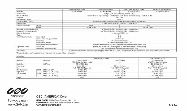
Digital Day/Night model True Day/Night model WDR Digital Day/Night model WDR True Day/Night modelModel No. ZC-D5212NXA ZC-DN5212NXA ZC-DW5212NXA ZC-DWN5212NXAPrivacy Mask ON (16 spots max., 10 colors, mosaic) / OFFMotion detection Detects all areas. 6 (horizontal) × 4 (vertical), 24 pixels in total (minimum block), sensitivity (1–10)Stabilizer ON / OFFMonitor output mode CRT / LCDCommunication function RS485 communication, half duplex (models with communication function only)Power source 24 V AC ± 10% (50/60 Hz ± 1 Hz) or 12 V DC ± 10%Power consumption DC12V 180mA 230mA
AC24V 190mA, 2.7W 240mA, 3.0WOperating temperature/humidity -10°C to +50°C, 85% or lower humidity (no condensing)Storage temperature/humidity -20°C to +60°C, 95% or lower humidity (no condensing)External dimensions 144 (ø) mm x 110 (H) mm Weight 500gInput/Output terminals Video output BNC
Service monitor output terminal 2P connectorPower input 2P screw terminal blockB/W Mode-Fix terminal 2P screw terminal block AWG16-30RS485 communication terminal 2P screw terminal block AWG16-30 (models with communication function only)
Adjustment switch OSD switch Push-button switch with 5 contact points (in 4 directions and at a central point)Termination resistance switch Slide switch (models with communication function only)
Accessories Cable for service monitor, Adapter ring, self-tapping screws (M4 × 20: 2 pcs.), Template, OSD Operation Manual, Instruction manual (this document)
* The specifications and/or appearance of the product may change without a prior notice.
Lens typesDigital Day/Night model True Day/Night model
Model No. EDR type ZC-D5550NXA ZC-D5025NXA ZC-DN5840NXAWDR Digital Day/Night model — WDR True Day/Night model
Model No. WDR type ZC-DW5550NXA — ZC-DWN5840NXAFocal length 5 mm - 50 mm 2.3 mm - 5.0 mm 8.5 mm - 40 mmIris F1.3 - F360C (DC auto iris) F1.2 - F360C (DC auto iris) F1.3 - F360C (DC auto iris)Min. IlluminanceNight modeAGC Extreme
50IRE SENS UP: OFF 0.030 lx (B/W) 0.027 lx (B/W) 0.008 lx (B/W)SENS UP: ON (x512) 0.00006 lx (B/W) 0.000053 lx (B/W) 0.000016 lx (B/W)
30IRE SENS UP: OFF 0.015 lx (B/W) 0.014 lx (B/W) 0.004 lx (B/W)SENS UP: ON (x512) 0.00003 lx (B/W) 0.00003 lx (B/W) 0.000008 lx (B/W)
Weight 570g 510g 560g