Embed Size (px)
Citation preview
CANNON STANDARD page 1 of 22
ASSEMBLY AND WIRING INSTRUCTION
KPT / KPSE / KPTC Miniature Circular Connector
CAS25098E
Bearbeitet: Geprüft: Norm: Änd.-Stand: Änd.-Datum:
AKU BR / AR - 4493W 26.07.2013 ITT Cannon GmbH, D-71384 Weinstadt
IMS Vorlage: R&D_06, Ausgabestand: März 2006
1 General Information ................................................................................................................. 2
1.0 Scope .......................................................................................................................... 2
2 Connector Type ....................................................................................................................... 2
2.0 Shell Style Plug ........................................................................................................... 2 2.1 Shell Style Receptacle ................................................................................................ 3
3 Contacts and Assembly Tools ................................................................................................. 3
3.0 Crimp Contacts ........................................................................................................... 3 3.1 Crimping Tools Description ......................................................................................... 4 3.2 Crimping Tools Order References .............................................................................. 5 3.3 Insertion Tools ............................................................................................................ 6 3.4 Extraction Tools .......................................................................................................... 6 3.5 Pipe Wrench ............................................................................................................... 7
4 Preparation and Crimping Instructions .................................................................................... 7
4.0 Dimensions for Single Conductor and Wire Stripping ............................................... 7 4.1 Wire Stripping Length and Selector Proposal ............................................................. 8 4.2 Instructions for the Crimping Process of Machined Contacts ..................................... 9 4.3 Wire Hole Fillers .......................................................................................................... 9
5 Soldering of contacts KPT ..................................................................................................... 10
5.0 Soldering Process ..................................................................................................... 10 5.1 Assembly Accessories .............................................................................................. 10
6 Assembly of Contacts ............................................................................................................ 11
6.0 Preparation of Shielded System Cable ..................................................................... 11 6.1 Overview, Configuration and Preparation for Contact Installation ............................ 11 6.2 Insertion of Contacts ................................................................................................. 12
7 Assembly Instruction of a Connector with DZ Adapter .......................................................... 16
8 Removal of Contacts ............................................................................................................. 19
8.0 Removal of Contacts for KPTC ................................................................................. 19 8.1 Removal of Contacts for KPSE ................................................................................. 19 8.2 Current Design KPSE ............................................................................................... 20 8.3 New Design KPSE .................................................................................................... 20
9 Annex ..................................................................................................................................... 21
9.0 Useful Hints ............................................................................................................... 21 9.1 Product Safety Information ....................................................................................... 22
CANNON STANDARD page 2 of 22
ASSEMBLY AND WIRING INSTRUCTION
KPT / KPSE / KPTC Miniature Circular Connector
CAS25098E
Bearbeitet: Geprüft: Norm: Änd.-Stand: Änd.-Datum:
AKU BR / AR - 4493W 26.07.2013 ITT Cannon GmbH, D-71384 Weinstadt
IMS Vorlage: R&D_06, Ausgabestand: März 2006
1 General Information
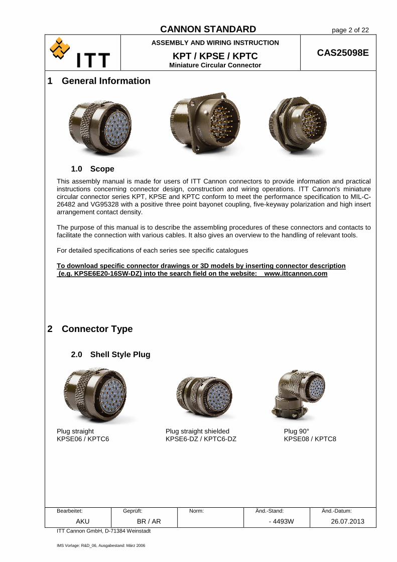
1.0 Scope
This assembly manual is made for users of ITT Cannon connectors to provide information and practical instructions concerning connector design, construction and wiring operations. ITT Cannon's miniature circular connector series KPT, KPSE and KPTC conform to meet the performance specification to MIL-C-26482 and VG95328 with a positive three point bayonet coupling, five-keyway polarization and high insert arrangement contact density. The purpose of this manual is to describe the assembling procedures of these connectors and contacts to facilitate the connection with various cables. It also gives an overview to the handling of relevant tools. For detailed specifications of each series see specific catalogues To download specific connector drawings or 3D models by inserting connector description (e.g. KPSE6E20-16SW-DZ) into the search field on the website: www.ittcannon.com
2 Connector Type
2.0 Shell Style Plug
Plug straight Plug straight shielded Plug 90° KPSE06 / KPTC6 KPSE6-DZ / KPTC6-DZ KPSE08 / KPTC8

CANNON STANDARD page 3 of 22
ASSEMBLY AND WIRING INSTRUCTION
KPT / KPSE / KPTC Miniature Circular Connector
CAS25098E
Bearbeitet: Geprüft: Norm: Änd.-Stand: Änd.-Datum:
AKU BR / AR - 4493W 26.07.2013 ITT Cannon GmbH, D-71384 Weinstadt
IMS Vorlage: R&D_06, Ausgabestand: März 2006
2.1 Shell Style Receptacle
Wall mounting Cable connecting Jam nut KPSE00 / KPTC0 KPSE01 / KPTC1 KPSE07 / KPTC7
Box mounting DZ-Adapter Thru Bulkhead KPSE02 / KPTC2 KPSE07 / KPTC7 KTB
3 Contacts and Assembly Tools
3.0 Crimp Contacts
KPSE / VG95328 Contact size Contact type Contact order reference
KPSE ver sion VG95328 version
20 Socket with insulation support 031-8704-203 031-8704-203
Pin with insulation support 430-8560-006 430-8560-006
16 Socket 031-8704-000 031-8704-000
Pin 430-8560-004 430-8560-004
12 Socket 031-8704-012 -
Pin 430-8560-016 - Grounding Pin 430-8560-020 -
KPTC For shell size 8 and contact layout 12 – 14 only
Contact size Contact order reference Contact size Contact order reference
20 Socket 031-8704-508 - hard gold plated hard silver plated
Pin 430-8560-404
16 Socket 031-8704-502 20 Socket 031-8704-509 031-8704-506
Pin 430-8560-406 20 Pin 430-8560-411 430-8560-410
KPT14A4 Contact size Contact order reference
Coaxial Socket DM 53742-5001
Pin DM 53740-5001
CANNON STANDARD page 4 of 22
ASSEMBLY AND WIRING INSTRUCTION
KPT / KPSE / KPTC Miniature Circular Connector
CAS25098E
Bearbeitet: Geprüft: Norm: Änd.-Stand: Änd.-Datum:
AKU BR / AR - 4493W 26.07.2013 ITT Cannon GmbH, D-71384 Weinstadt
IMS Vorlage: R&D_06, Ausgabestand: März 2006
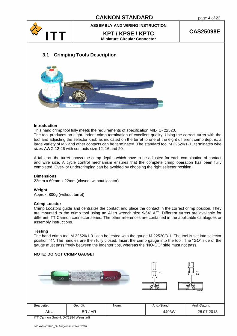
3.1 Crimping Tools Description
Introduction This hand crimp tool fully meets the requirements of specification MIL- C- 22520. The tool produces an eight- indent crimp termination of excellent quality. Using the correct turret with the tool and adjusting the selector knob as indicated on the turret to one of the eight different crimp depths, a large variety of MS and other contacts can be terminated. The standard tool M 22520/1-01 terminates wire sizes AWG 12-26 with contacts size 12, 16 and 20. A table on the turret shows the crimp depths which have to be adjusted for each combination of contact and wire size. A cycle control mechanism ensures that the complete crimp operation has been fully completed. Over- or undercrimping can be avoided by choosing the right selector position. Dimensions 22mm x 60mm x 22mm (closed, without locator) Weight Approx. 800g (without turret) Crimp Locator Crimp Locators guide and centralize the contact and place the contact in the correct crimp position. They are mounted to the crimp tool using an Allen wrench size 9/64” A/F. Different turrets are available for different ITT Cannon connector series. The other references are contained in the applicable catalogues or assembly instructions. Testing The hand crimp tool M 22520/1-01 can be tested with the gauge M 22520/3-1. The tool is set into selector position “4”. The handles are then fully closed. Insert the crimp gauge into the tool. The “GO” side of the gauge must pass freely between the indenter tips, whereas the “NO-GO” side must not pass. NOTE: DO NOT CRIMP GAUGE!
CANNON STANDARD page 5 of 22
ASSEMBLY AND WIRING INSTRUCTION
KPT / KPSE / KPTC Miniature Circular Connector
CAS25098E
Bearbeitet: Geprüft: Norm: Änd.-Stand: Änd.-Datum:
AKU BR / AR - 4493W 26.07.2013 ITT Cannon GmbH, D-71384 Weinstadt
IMS Vorlage: R&D_06, Ausgabestand: März 2006
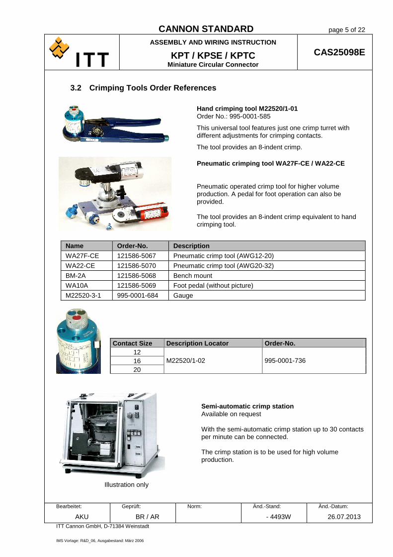
3.2 Crimping Tools Order References
Hand crimping tool M22520/1-01 Order No.: 995-0001-585
This universal tool features just one crimp turret with different adjustments for crimping contacts.
The tool provides an 8-indent crimp.
Pneumatic crimping tool WA27F-CE / WA22-CE Pneumatic operated crimp tool for higher volume production. A pedal for foot operation can also be provided. The tool provides an 8-indent crimp equivalent to hand crimping tool.
Name Order-No. Description
WA27F-CE 121586-5067 Pneumatic crimp tool (AWG12-20)
WA22-CE 121586-5070 Pneumatic crimp tool (AWG20-32)
BM-2A 121586-5068 Bench mount
WA10A 121586-5069 Foot pedal (without picture)
M22520-3-1 995-0001-684 Gauge
Contact Size Description Locator Order-No. 12
M22520/1-02 995-0001-736 16 20
Illustration only
Semi-automatic crimp station Available on request With the semi-automatic crimp station up to 30 contacts per minute can be connected. The crimp station is to be used for high volume production.
CANNON STANDARD page 6 of 22
ASSEMBLY AND WIRING INSTRUCTION
KPT / KPSE / KPTC Miniature Circular Connector
CAS25098E
Bearbeitet: Geprüft: Norm: Änd.-Stand: Änd.-Datum:
AKU BR / AR - 4493W 26.07.2013 ITT Cannon GmbH, D-71384 Weinstadt
IMS Vorlage: R&D_06, Ausgabestand: März 2006
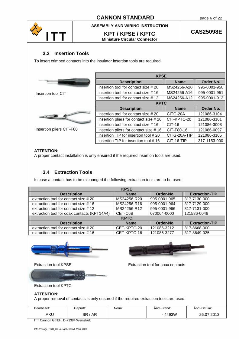
3.3 Insertion Tools
To insert crimped contacts into the insulator insertion tools are required.
Insertion tool CIT
KPSE Description Name Order No.
insertion tool for contact size # 20 MS24256-A20 995-0001-950 insertion tool for contact size # 16 MS24256-A16 995-0001-951 insertion tool for contact size # 12 MS24256-A12 995-0001-913
KPTC Description Name Order No.
insertion tool for contact size # 20 CITG-20A 121086-3104 insertion pliers for contact size # 20 CIT-KPTC-20 121086-3101 insertion tool for contact size # 16 CIT-16 121086-3008 insertion pliers for contact size # 16 CIT-F80-16 121086-0097 insertion TIP for insertion tool # 20 CITG-20A-TIP 121086-3105 insertion TIP for insertion tool # 16 CIT-16-TIP 317-1153-000
Insertion pliers CIT-F80
ATTENTION: A proper contact installation is only ensured if the required insertion tools are used.
3.4 Extraction Tools
In case a contact has to be exchanged the following extraction tools are to be used:
KPSE Description Name Order -No. Extraction -TIP
extraction tool for contact size # 20 MS24256-R20 995-0001-965 317-7130-000 extraction tool for contact size # 16 MS24256-R16 995-0001-964 317-7129-000 extraction tool for contact size # 12 MS24256-R12 995-0001-966 317-7131-000 extraction tool for coax contacts (KPT14A4) CET-C6B 070064-0000 121586-0046
KPTC Description Name Order -No. Extraction -TIP
extraction tool for contact size # 20 CET-KPTC-20 121086-3212 317-8668-000 extraction tool for contact size # 16 CET-KPTC-16 121086-3277 317-8649-025
Extraction tool KPSE Extraction tool for coax contacts
Extraction tool KPTC
ATTENTION: A proper removal of contacts is only ensured if the required extraction tools are used.
CANNON STANDARD page 7 of 22
ASSEMBLY AND WIRING INSTRUCTION
KPT / KPSE / KPTC Miniature Circular Connector
CAS25098E
Bearbeitet: Geprüft: Norm: Änd.-Stand: Änd.-Datum:
AKU BR / AR - 4493W 26.07.2013 ITT Cannon GmbH, D-71384 Weinstadt
IMS Vorlage: R&D_06, Ausgabestand: März 2006
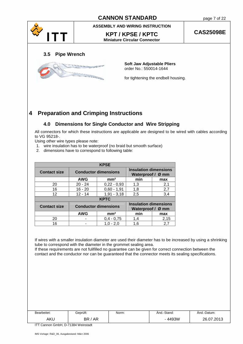
3.5 Pipe Wrench
Soft Jaw Adjustable Pliers order No.: 550014-1644 for tightening the endbell housing.
4 Preparation and Crimping Instructions
4.0 Dimensions for Single Conductor and Wire Stripping
All connectors for which these instructions are applicable are designed to be wired with cables according to VG 95218-. Using other wire types please note: 1. wire insulation has to be waterproof (no braid but smooth surface) 2. dimensions have to correspond to following table:
If wires with a smaller insulation diameter are used their diameter has to be increased by using a shrinking tube to correspond with the diameter in the grommet sealing area. If these requirements are not fulifilled no guarantee can be given for correct connection between the contact and the conductor nor can be guaranteed that the connector meets its sealing specifications.
KPSE
Contact size Conductor dimensions Insulation dimensions Waterproof / Ø mm
AWG mm² min max 20 20 - 24 0,22 - 0,93 1,3 2,1 16 16 - 20 0,60 - 1,91 1,8 2,7 12 12 - 14 1,91 - 3,18 2,5 3,4
KPTC
Contact size Conductor dimensions Insulation dimensions Waterproof / Ø mm
AWG mm² min max 20 - 0,4 - 0,75 1,4 2,15 16 - 1,0 - 2,0 1,6 2,7
CANNON STANDARD page 8 of 22
ASSEMBLY AND WIRING INSTRUCTION
KPT / KPSE / KPTC Miniature Circular Connector
CAS25098E
Bearbeitet: Geprüft: Norm: Änd.-Stand: Änd.-Datum:
AKU BR / AR - 4493W 26.07.2013 ITT Cannon GmbH, D-71384 Weinstadt
IMS Vorlage: R&D_06, Ausgabestand: März 2006
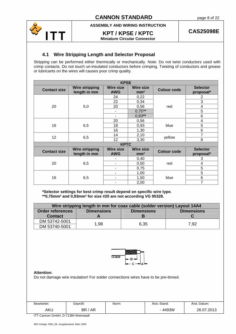
4.1 Wire Stripping Length and Selector Proposal
Stripping can be performed either thermically or mechanically. Note: Do not twist conductors used with crimp contacts. Do not touch un-insulated conductors before crimping. Twisting of conductors and grease or lubricants on the wires will causes poor crimp quality.
*Selector settings for best crimp result depend on specific wire type. **0,75mm² and 0,93mm² for size #20 are not accordi ng VG 95328.
Wire stripping length in mm for coax cable (solder version) Layout 14A4 Order references
Contact Dimensions
A Dimensions
B Dimensions
C DM 53742-5001
1,98 6,35 7,92 DM 53740-5001
Attention: Do not damage wire insulation! For solder connections wires have to be pre-tinned.
KPSE
Contact size Wire stripping length in mm
Wire s ize AWG
Wire size mm² Colour code Selector
proposal*
20 5,0
24 0,22
red
2 22 0,34 3 20 0,56 4 - 0,75** 5 - 0,93** 6
16 6,5 20 0,56
blue 4
18 0,93 5 16 1,30 6
12 6,5 14 2,10
yellow 7
12 3,30 8 KPTC
Contact size Wire strippin g length in mm
Wire size AWG
Wire size mm² Colour code
Selector proposal*
20 6,5 - 0,40
red 3
- 0,50 4 - 0,75 5
16 6,5 - 1,00
blue 5
- 1,50 6 - 2,00 7

CANNON STANDARD page 9 of 22
ASSEMBLY AND WIRING INSTRUCTION
KPT / KPSE / KPTC Miniature Circular Connector
CAS25098E
Bearbeitet: Geprüft: Norm: Änd.-Stand: Änd.-Datum:
AKU BR / AR - 4493W 26.07.2013 ITT Cannon GmbH, D-71384 Weinstadt
IMS Vorlage: R&D_06, Ausgabestand: März 2006
4.2 Instructions for the Crimping Process of Machined Contacts
1.) strip wires to lengths, for stripping details see 4.1. 2.) open hand tool and insert the contact in the crimp locator 3.) position the stripped cable into the contact crimp pot 4.) close hand tool to end position 5.) open hand tool and extract the contact, check the contact visually 6.) minimum crimp tensile requirements see DIN EN 60352-2-2006
- there shall be no loose strands out of the crimp section - the contact must be crimped straight to the cable - deformed contacts must not be used. In this case exchange defect contact. - during the preparation, strands must not be injured or cut
1 insulation of cable 2 wire 3 contact 4 inspection hole (wire strands must be visible)
4.3 Wire Hole Fillers
Where contacts are not used, the cavities are to be closed by wire hole filler.
Assembly hint: Non used contact cavities have to be closed by an unwired contact, while the relevant wire hole filler has to be inserted into the empty cavity of the grommet. Wire hole fillers are colored coded!
KPSE size part no. colour
20 225-1012-000 red
16 225-1011-000 blue 12 225-1010-000 yellow
Coaxial 14A4 225-1018-000 yellow KPTC
size part no. colour 20 225-1012-000 red 16 225-1011-000 blue
loose wire strand
no wire strand visible
CANNON STANDARD page 10 of 22
ASSEMBLY AND WIRING INSTRUCTION
KPT / KPSE / KPTC Miniature Circular Connector
CAS25098E
Bearbeitet: Geprüft: Norm: Änd.-Stand: Änd.-Datum:
AKU BR / AR - 4493W 26.07.2013 ITT Cannon GmbH, D-71384 Weinstadt
IMS Vorlage: R&D_06, Ausgabestand: März 2006
5 Soldering of contacts KPT
5.0 Soldering Process
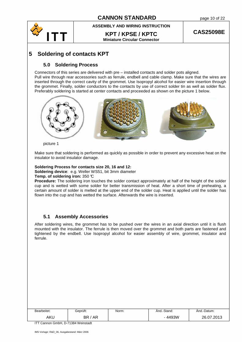
Connectors of this series are delivered with pre – installed contacts and solder pots aligned. Pull wire through rear accessories such as ferrule, endbell and cable clamp. Make sure that the wires are inserted through the correct cavity of the grommet. Use Isopropyl alcohol for easier wire insertion through the grommet. Finally, solder conductors to the contacts by use of correct solder tin as well as solder flux. Preferably soldering is started at center contacts and proceeded as shown on the picture 1 below.
picture 1
Make sure that soldering is performed as quickly as possible in order to prevent any excessive heat on the insulator to avoid insulator damage.
Soldering Process for contacts size 20, 16 and 12: Soldering device : e.g. Weller WS51, bit 3mm diameter Temp. of soldering iron: 350 °C Procedure: The soldering iron touches the solder contact approximately at half of the height of the solder cup and is wetted with some solder for better transmission of heat. After a short time of preheating, a certain amount of solder is melted at the upper end of the solder cup. Heat is applied until the solder has flown into the cup and has wetted the surface. Afterwards the wire is inserted.
5.1 Assembly Accessories
After soldering wires, the grommet has to be pushed over the wires in an axial direction until it is flush mounted with the insulator. The ferrule is then moved over the grommet and both parts are fastened and tightened by the endbell. Use Isopropyl alcohol for easier assembly of wire, grommet, insulator and ferrule.

CANNON STANDARD page 11 of 22
ASSEMBLY AND WIRING INSTRUCTION
KPT / KPSE / KPTC Miniature Circular Connector
CAS25098E
Bearbeitet: Geprüft: Norm: Änd.-Stand: Änd.-Datum:
AKU BR / AR - 4493W 26.07.2013 ITT Cannon GmbH, D-71384 Weinstadt
IMS Vorlage: R&D_06, Ausgabestand: März 2006
6 Assembly of Contacts
6.0 Preparation of Shielded System Cable
• The stripping length of the shielded cable has to be determined in line with the com. size/length. The outer cable jacked should end close to the endbell. The stripping of cable must be carried out with right stripping unit. Thereby the shielding braid must not be damaged.
• Fold back braid over jacked and remove the protective foil if necessary.
• Fix the shielding braid with a tape for easier assembly.
• Strip the wire insulation of the conductors. • Stripping lengths see 4.1.
• Crimp the contacts, see 4.2.
6.1 Overview, Configuration and Preparation for Contact Installation
1. Pull crimped contact through all accessories, such as ferrule, endbell and cable clamp or others. 2. Fix the plug in the assembly adapter and mate with each other. Optionally an empty mating half shell is utilized to fix the connector in an appropriate manner.
Slide all rear parts on the cable before assembling contacts into barrel and insulator. Pay attention to the correct order and mounting direction of all parts, as pictured. Hint: Use a tie wrap for fixing all parts on the mounting area of the cable.
shielded cable
shielding braid
ASSEMBLY DIRECTION MOUNTING DIRECTION
CANNON STANDARD page 12 of 22
ASSEMBLY AND WIRING INSTRUCTION
KPT / KPSE / KPTC Miniature Circular Connector
CAS25098E
Bearbeitet: Geprüft: Norm: Änd.-Stand: Änd.-Datum:
AKU BR / AR - 4493W 26.07.2013 ITT Cannon GmbH, D-71384 Weinstadt
IMS Vorlage: R&D_06, Ausgabestand: März 2006
The second option is, you slide all parts over the cable before you crimp the contacts, see illustration below.
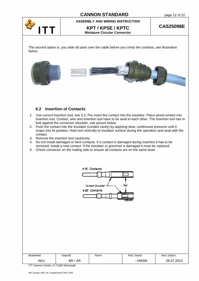
6.2 Insertion of Contacts
1. Use correct insertion tool, see 3.3. Pre insert the contact into the insulator. Place wired contact into insertion tool. Contact, wire and insertion tool have to be axial to each other. The insertion tool has to butt against the connector shoulder, see picture below.
2. Push the contact into the insulator (contact cavity) by applying slow, continuous pressure until it snaps into its position. Hold tool vertically to insulator surface during the operation and axial with the contact.
3. Remove the insertion tool cautiously. 4. Do not install damaged or bent contacts. If a contact is damaged during insertion it has to be
removed. Install a new contact. If the insulator or grommet is damaged it must be replaced. 5. Check connector on the mating side to ensure all contacts are on the same level.
CANNON STANDARD page 13 of 22
ASSEMBLY AND WIRING INSTRUCTION
KPT / KPSE / KPTC Miniature Circular Connector
CAS25098E
Bearbeitet: Geprüft: Norm: Änd.-Stand: Änd.-Datum:
AKU BR / AR - 4493W 26.07.2013 ITT Cannon GmbH, D-71384 Weinstadt
IMS Vorlage: R&D_06, Ausgabestand: März 2006
1
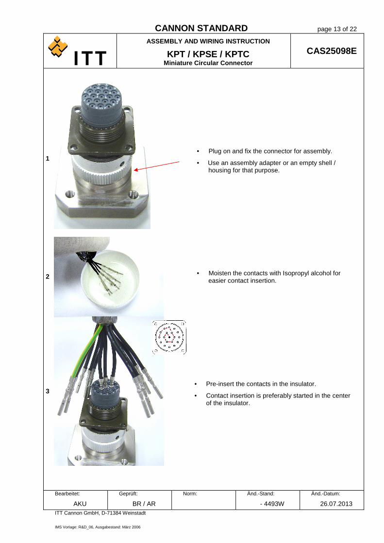
• Plug on and fix the connector for assembly.
• Use an assembly adapter or an empty shell / housing for that purpose.
2
• Moisten the contacts with Isopropyl alcohol for easier contact insertion.
3
• Pre-insert the contacts in the insulator.
• Contact insertion is preferably started in the center of the insulator.
CANNON STANDARD page 14 of 22
ASSEMBLY AND WIRING INSTRUCTION
KPT / KPSE / KPTC Miniature Circular Connector
CAS25098E
Bearbeitet: Geprüft: Norm: Änd.-Stand: Änd.-Datum:
AKU BR / AR - 4493W 26.07.2013 ITT Cannon GmbH, D-71384 Weinstadt
IMS Vorlage: R&D_06, Ausgabestand: März 2006
4
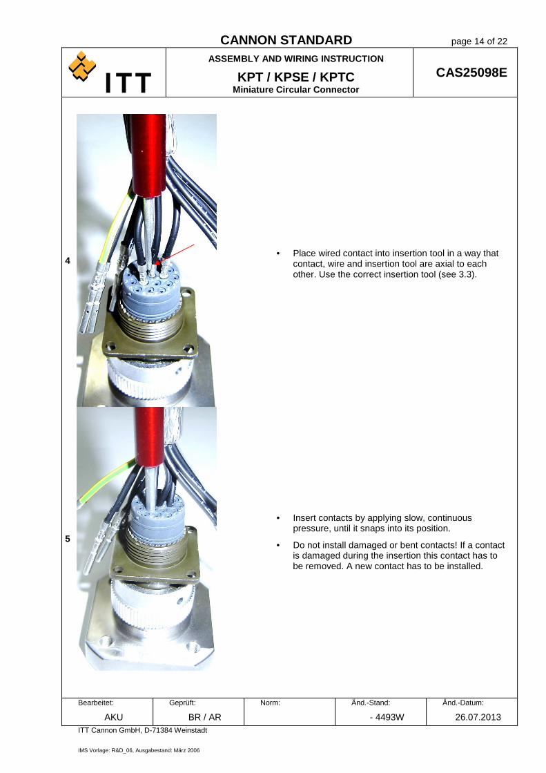
• Place wired contact into insertion tool in a way that contact, wire and insertion tool are axial to each other. Use the correct insertion tool (see 3.3).
5
• Insert contacts by applying slow, continuous pressure, until it snaps into its position.
• Do not install damaged or bent contacts! If a contact is damaged during the insertion this contact has to be removed. A new contact has to be installed.
CANNON STANDARD page 15 of 22
ASSEMBLY AND WIRING INSTRUCTION
KPT / KPSE / KPTC Miniature Circular Connector
CAS25098E
Bearbeitet: Geprüft: Norm: Änd.-Stand: Änd.-Datum:
AKU BR / AR - 4493W 26.07.2013 ITT Cannon GmbH, D-71384 Weinstadt
IMS Vorlage: R&D_06, Ausgabestand: März 2006
6
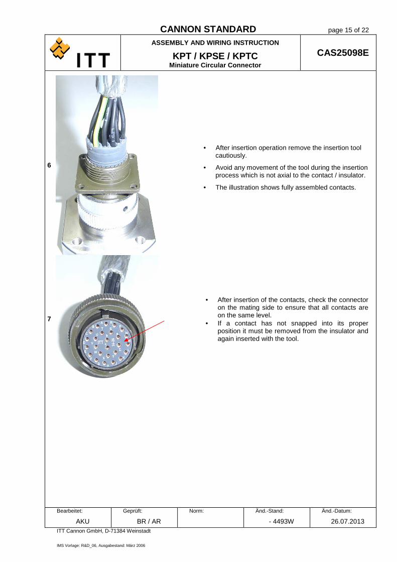
• After insertion operation remove the insertion tool cautiously.
• Avoid any movement of the tool during the insertion process which is not axial to the contact / insulator.
• The illustration shows fully assembled contacts.
7
• After insertion of the contacts, check the connector on the mating side to ensure that all contacts are on the same level.
• If a contact has not snapped into its proper position it must be removed from the insulator and again inserted with the tool.
CANNON STANDARD page 16 of 22
ASSEMBLY AND WIRING INSTRUCTION
KPT / KPSE / KPTC Miniature Circular Connector
CAS25098E
Bearbeitet: Geprüft: Norm: Änd.-Stand: Änd.-Datum:
AKU BR / AR - 4493W 26.07.2013 ITT Cannon GmbH, D-71384 Weinstadt
IMS Vorlage: R&D_06, Ausgabestand: März 2006
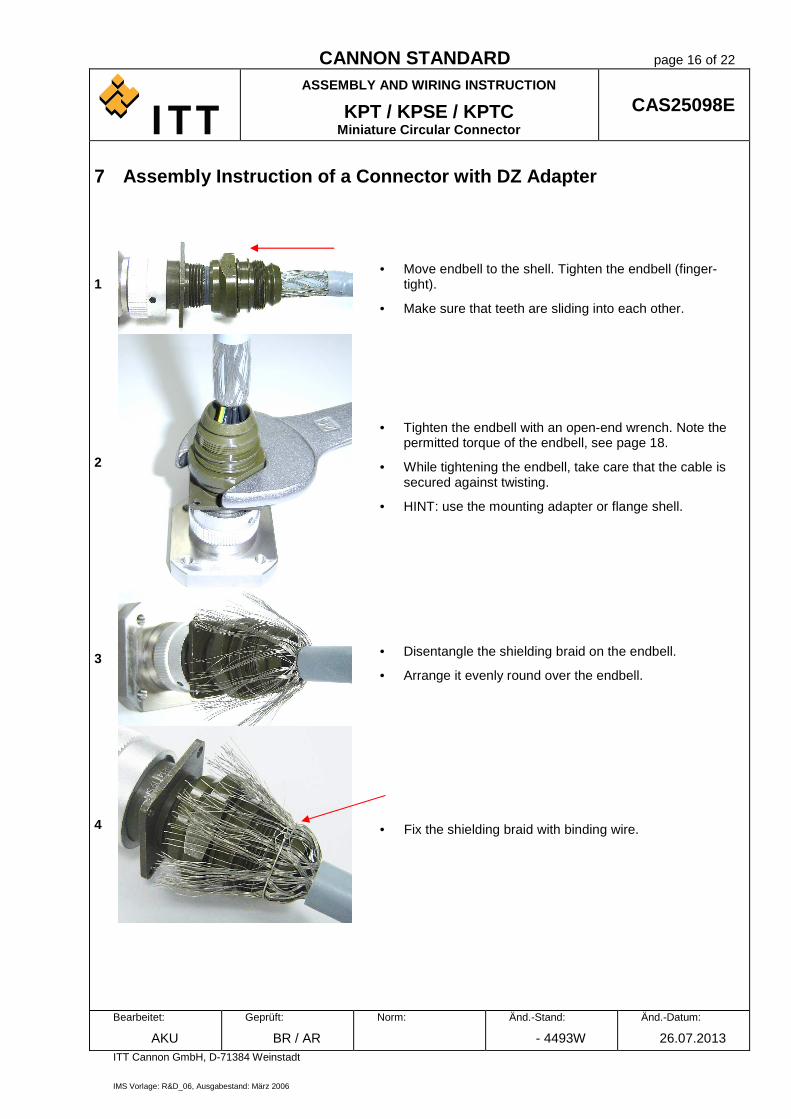
7 Assembly Instruction of a Connector with DZ Adapt er
1
• Move endbell to the shell. Tighten the endbell (finger-tight).
• Make sure that teeth are sliding into each other.
2
• Tighten the endbell with an open-end wrench. Note the permitted torque of the endbell, see page 18.
• While tightening the endbell, take care that the cable is secured against twisting.
• HINT: use the mounting adapter or flange shell.
3
• Disentangle the shielding braid on the endbell.
• Arrange it evenly round over the endbell.
4
• Fix the shielding braid with binding wire.
CANNON STANDARD page 17 of 22
ASSEMBLY AND WIRING INSTRUCTION
KPT / KPSE / KPTC Miniature Circular Connector
CAS25098E
Bearbeitet: Geprüft: Norm: Änd.-Stand: Änd.-Datum:
AKU BR / AR - 4493W 26.07.2013 ITT Cannon GmbH, D-71384 Weinstadt
IMS Vorlage: R&D_06, Ausgabestand: März 2006
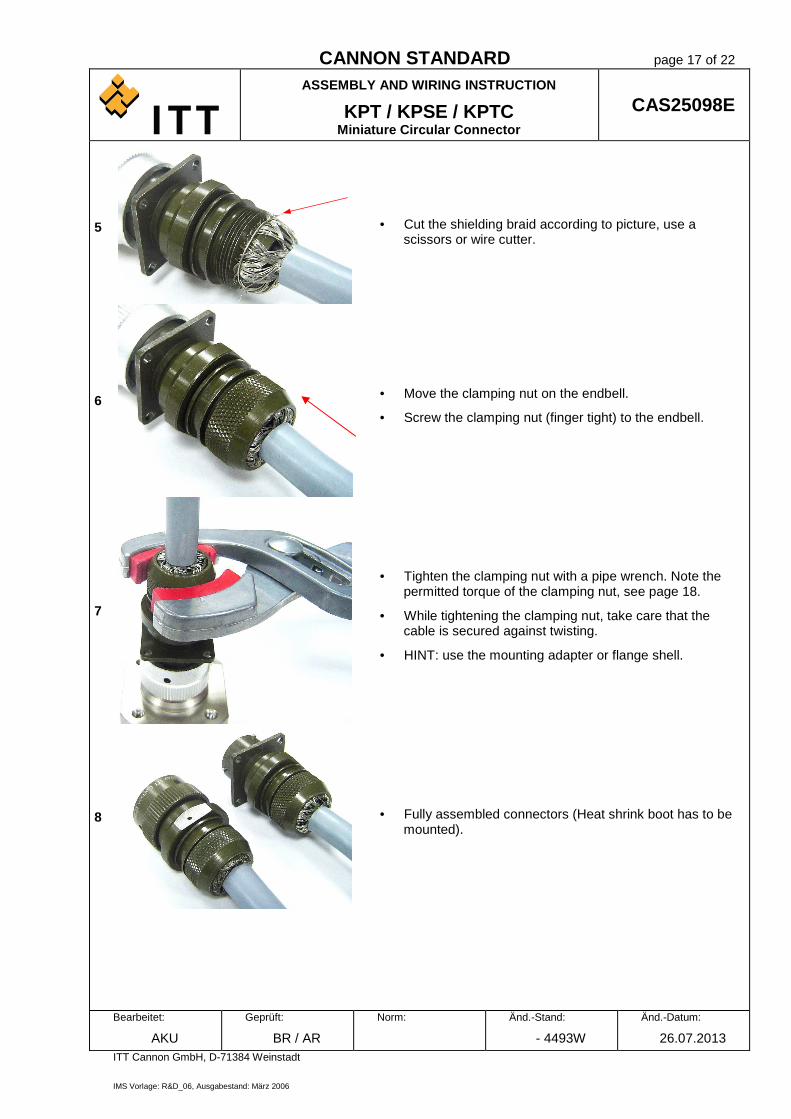
5
• Cut the shielding braid according to picture, use a scissors or wire cutter.
6
• Move the clamping nut on the endbell.
• Screw the clamping nut (finger tight) to the endbell.
7
• Tighten the clamping nut with a pipe wrench. Note the permitted torque of the clamping nut, see page 18.
• While tightening the clamping nut, take care that the cable is secured against twisting.
• HINT: use the mounting adapter or flange shell.
8
• Fully assembled connectors (Heat shrink boot has to be mounted).

CANNON STANDARD page 18 of 22
ASSEMBLY AND WIRING INSTRUCTION
KPT / KPSE / KPTC Miniature Circular Connector
CAS25098E
Bearbeitet: Geprüft: Norm: Änd.-Stand: Änd.-Datum:
AKU BR / AR - 4493W 26.07.2013 ITT Cannon GmbH, D-71384 Weinstadt
IMS Vorlage: R&D_06, Ausgabestand: März 2006
ENDBELL/BACKSHELL GLAND NUT
Shell size Tightening torque Permissible tolerances ± 5%
Tightening torque Permissible tolerances ±5%
8 4,0 Nm 4,0 Nm 10 6,0 Nm 6,0 Nm 12 8,0 Nm 8,0 Nm 14 10,0 Nm 10,0 Nm 16 10,0 Nm 10,0 Nm 18 13,0 Nm 13,0 Nm 20 13,0 Nm 13,0 Nm 22 13,0 Nm 13,0 Nm 24 13,0 Nm 13,0 Nm
Table1: permitted tightening torques, standard VG 95328
9
• To finalize the assembly process a heat shrink boot has to be mounted to the connector endbell and the cable jacked.
• Heat shrinkable boots have to be purchased separately according VG 95343-3.
10
Jam Nut / Tightening torque for single hole mountin g styles D, E, F, S and T. Permissible tolerances ± 5% Shell size
8 10,0 Nm 10 16,0 Nm 12 20,0 Nm 14 20,0 Nm 16 30,0 Nm 18 30,0 Nm 20 30,0 Nm 22 40,0 Nm 24 40,0 Nm
Table2: permitted tightening torques, standard VG 95328
CANNON STANDARD page 19 of 22
ASSEMBLY AND WIRING INSTRUCTION
KPT / KPSE / KPTC Miniature Circular Connector
CAS25098E
Bearbeitet: Geprüft: Norm: Änd.-Stand: Änd.-Datum:
AKU BR / AR - 4493W 26.07.2013 ITT Cannon GmbH, D-71384 Weinstadt
IMS Vorlage: R&D_06, Ausgabestand: März 2006
Torque for screws at the flanges
Thread Max. admissible torque M3 1,2±0,2 Nm M4 1,4±0,2 Nm M5 2,0±0,2 Nm
8 Removal of Contacts 1. All accessories are removed in reversed direction (see assembly instruction). 2. Use the correct extraction tool as described in 3.4.
8.0 Removal of Contacts for KPTC
Place tool from the mating side parallel to its axis over the socket or pin contact. Apply smooth and continuous pressure towards the rear end of the connector to push contact out of the insulator. The operation is terminated as soon as the shoulder of the tool butts against the front of the insulator. Pull tool carefully out of the connector.
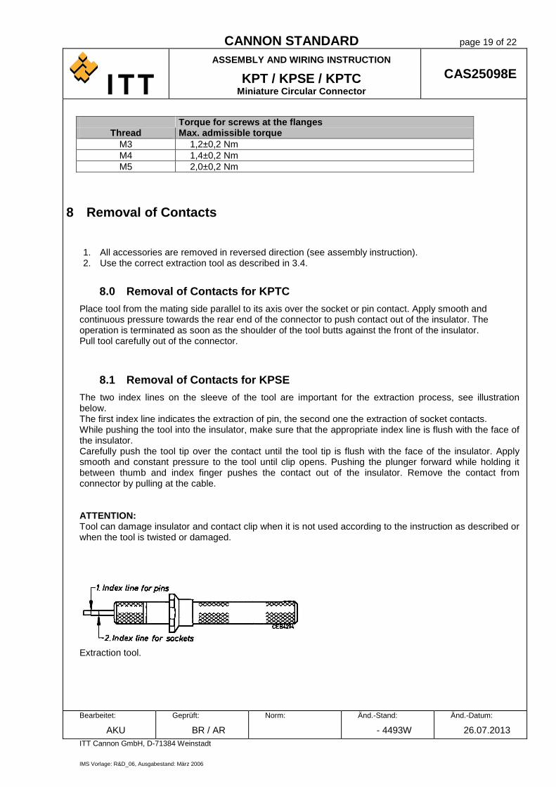
8.1 Removal of Contacts for KPSE
The two index lines on the sleeve of the tool are important for the extraction process, see illustration below. The first index line indicates the extraction of pin, the second one the extraction of socket contacts. While pushing the tool into the insulator, make sure that the appropriate index line is flush with the face of the insulator. Carefully push the tool tip over the contact until the tool tip is flush with the face of the insulator. Apply smooth and constant pressure to the tool until clip opens. Pushing the plunger forward while holding it between thumb and index finger pushes the contact out of the insulator. Remove the contact from connector by pulling at the cable. ATTENTION: Tool can damage insulator and contact clip when it is not used according to the instruction as described or when the tool is twisted or damaged.
Extraction tool.
CANNON STANDARD page 20 of 22
ASSEMBLY AND WIRING INSTRUCTION
KPT / KPSE / KPTC Miniature Circular Connector
CAS25098E
Bearbeitet: Geprüft: Norm: Änd.-Stand: Änd.-Datum:
AKU BR / AR - 4493W 26.07.2013 ITT Cannon GmbH, D-71384 Weinstadt
IMS Vorlage: R&D_06, Ausgabestand: März 2006
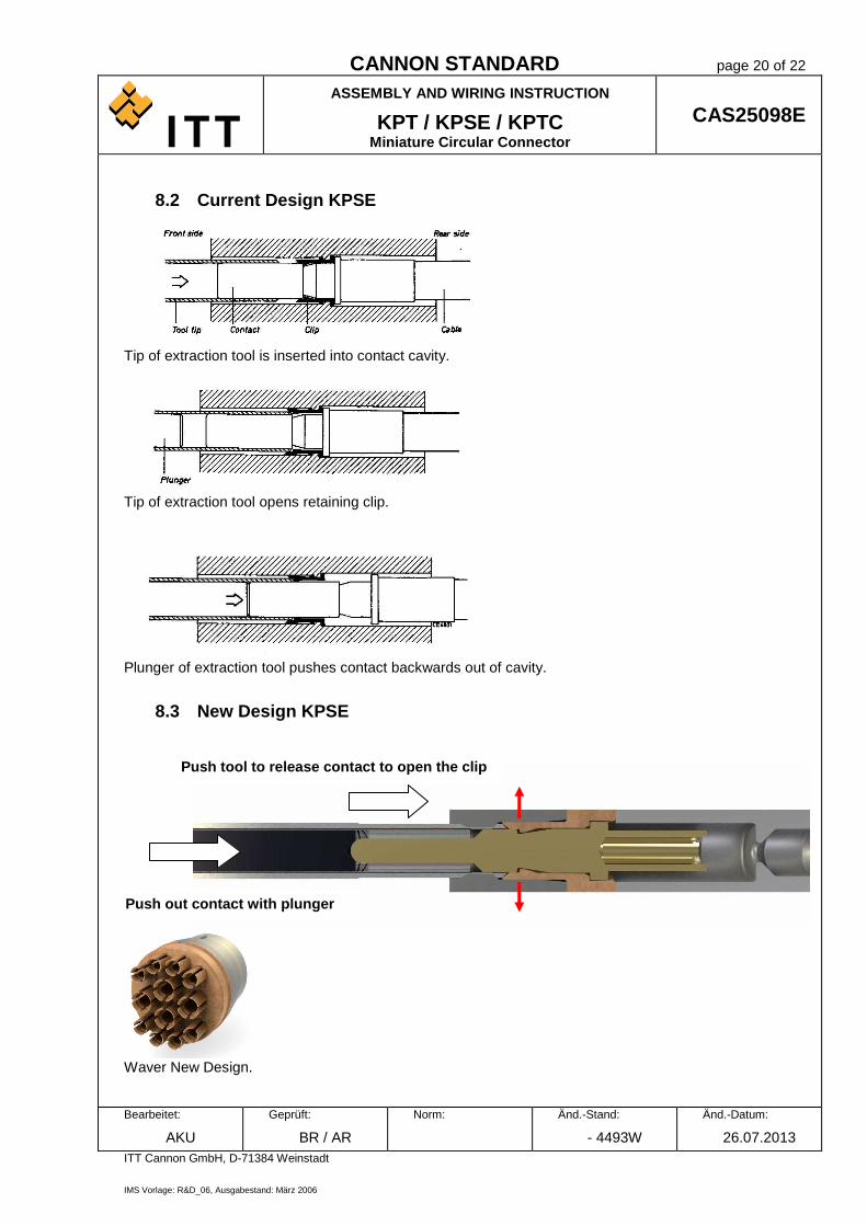
8.2 Current Design KPSE
Tip of extraction tool is inserted into contact cavity.
Tip of extraction tool opens retaining clip.
Plunger of extraction tool pushes contact backwards out of cavity.
8.3 New Design KPSE
Waver New Design.
Push tool to release contact to open the clip
Push out contact with plunger
CANNON STANDARD page 21 of 22
ASSEMBLY AND WIRING INSTRUCTION
KPT / KPSE / KPTC Miniature Circular Connector
CAS25098E
Bearbeitet: Geprüft: Norm: Änd.-Stand: Änd.-Datum:
AKU BR / AR - 4493W 26.07.2013 ITT Cannon GmbH, D-71384 Weinstadt
IMS Vorlage: R&D_06, Ausgabestand: März 2006
9 Annex
9.0 Useful Hints Keep hands, working place and connectors clean and free of any grease. Check tools, connectors, accessories, cable sizes and other aids for correct part number and size. Cable/wire cutting and stripping Cut wire/cable in a way that a proper and even surface is achieved. Avoid indents, marks, or similar in the cutting area. During stripping of individual wires observe the stripping length depending on a contact size. Prevent any damage of individual strands. For solder connections pre-tin the conductor over the complete stripping length. Keep time of soldering the conductors to contacts already installed in the insulator as short as possible in order to prevent any damage to the insulator which may be caused by over-heating. To obtain good crimp connections please follow the rules: a) Use correct crimp tool with correct locator b) When terminating contacts sizes 60/100, 160 and 500 with the hydraulic crimp tool finalize crimping operations without
interruption c) Use correct insertion tool for individual contacts d) Stripped conductors have to be crimped in a proper way. The following simple tests can be made: Visual: Contacts are damaged during crimping (torn, bent, etc.) All wire strands must be inserted on the contact. Mechanical: Pull the terminated wire to check if crimp connection is properly made. Insert contacts straight into insulator. Do not insert damaged contacts. Maintain steady pressure when contacts are inserted. Do not use damaged insulators or grommets. Before insertion of wired contacts, slide hardware (grommet, endbell or cable clamp etc.) in proper order over the wire bundle. Please assure that the correct conductor is inserted into the correct cavity of the grommet. Isopropyl alcohol facilitates insertion of cable into grommet. Apply Isopropyl alcohol to the appropriate insulator cavity prior to insertion of contact. Inspect visually, if all socket or pin contacts are inserted properly, i.e. whether the mating ends of the contacts are all on same level. Mate shells resp. barrels with coupling nuts in correct assembly adapter. Do not harness without using assembly adapters or mating connectors. If required, lock endbell with Loctite or other locking compound. Loctite is to be stored at room temperature preferably below 20°C. Insert contacts from the rear and release them from the mating face of the connector. Extract contact only with the correct tool. Note: according to weight and tension (vibration, acceleration) the cable has to be seized and fixed at the suitable place.
CANNON STANDARD page 22 of 22
ASSEMBLY AND WIRING INSTRUCTION
KPT / KPSE / KPTC Miniature Circular Connector
CAS25098E
Bearbeitet: Geprüft: Norm: Änd.-Stand: Änd.-Datum:
AKU BR / AR - 4493W 26.07.2013 ITT Cannon GmbH, D-71384 Weinstadt
IMS Vorlage: R&D_06, Ausgabestand: März 2006
9.1 Product Safety Information 1. MATERIAL CONTENT AND PHYSICAL FORM Electrical connectors do not usually contain hazardous materials. They contain conducting and non-conducting materials and can be divided into two groups. a) Printed circuit types and low cost audio types which employ all plastic insulators and casings. b) Rugged, Fire Barrier and High Reliability types with metal casings and either natural rubber, synthetic rubber, plastic or glass insulating materials. Contact materials vary with type of connector and also application and are usually manufactured from either: Copper, copper alloys, nickel, alumel, chromel or steel. In special applications, other alloys may be specified. 2. FIRE CHARACTERISTICS AND ELECTRIC SHOCK HAZARD There is no fire hazard when the connector is correctly wired and used within the specified parameters. Incorrect wiring or assembly of the connector or careless use of metal tools or conductive fluids, or transit damage to any of the component parts may cause electric shock or burns. Live circuits must not be broken by separating mated connectors as this may cause arcing, ionization and burning. Heat dissipation is greater at maximum resistance in a circuit. Hot spots may occur when resistance is raised locally by damage, e.g. cracked or deformed contacts, broken strands of wire. Local overheating may also result from the use of the incorrect application tools or from poor quality soldering or slack screw terminals. Overheating may occur if the ratings in the product Data Sheet/Catalog are exceeded and can cause breakdown of insulation and hence electric shock. If heating is allowed to continue it intensifies by further increasing the local resistance through loss of temper of spring contacts, formation of oxide film on contacts and wires and leakage currents through carbonization of insulation and tracking paths. Fire can then result in the presence of combustible materials and this may release noxious fumes. Overheating may not be visually apparent. Burns may result from touching overheated components. 3. HANDLING Care must be taken to avoid damage to any component parts of electrical connectors during installation and use. Although there are normally no sharp edges, care must be taken when handling certain components to avoid injury to fingers. Electrical connectors may be damaged in transit to the customers, and damage may result in creation of hazards. Products should therefore be examined prior to installation/use and rejected if found to be damaged. 4. DISPOSAL Incineration of certain materials may release noxious or even toxic fumes. 5. APPLICATION Connectors with exposed contacts should not be selected for use on the current supply side of an electrical circuit, because an electric shock could result from touching exposed contacts on an unmated connector. Voltages in excess of 30 V ac or 42.5 V dc are potentially hazardous and care should be taken to ensure that such voltages cannot be transmitted in any way to exposed metal parts of the connector body. The connector and wiring should be checked, before making live, to have no damage to metal parts or insulators, no solder blobs, loose strands, conducting lubricants, swarf, or any other undesired conducting particles. Circuit resistance and continuity check should be made to make certain that there are no high resistance joints or spurious conducting paths. Always use the correct application tools as specified in the Data Sheet/Catalog. Do not permit untrained personnel to wire, assemble or tamper with connectors. For operation voltage please see appropriate national regulations. IMPORTANT GENERAL INFORMATION (i) Air and creepage paths/Operating voltage: The admissible operating voltages depend on the individual applications and the valid national and other applicable safety regulations. For this reason the air and creepage path data are only reference values. Observe reduction of air and creepage paths due to PC board and/or harnessing. (ii) Temperature: All information given are temperature limits. The operation temperature depends on the individual application. (iii) Other important information: Cannon continuously endeavors to improve their products. Therefore, Cannon products may deviate from the description, technical data and shape as shown in this assembly and wiring instruction. ITT Interconnect Solutions, a Division of ITT Corporation manufactures the highest quality products available in the marketplace; however these products are intended to be used in accordance with the specifications in this publication. Any use or application that deviates from the stated operating specifications is not recommended and may be unsafe. No information and data contained in this publication shall be construed to create any liability on the part of Cannon. Any new issue of this publication shall automatically invalidate and supersede any and all previous issues.