Embed Size (px)
Citation preview

8. WIRING DIAGRAM :
Wiring Diagram for ac, 3Phase, 4Wire, Dual Source Whole CurrentStatic Energy Meter
Meter Terminal Block
R
Y
B
N
Mains/Generator Selection : When ac 240V (± 20%) is available at P&N terminals
the energy shall be recorded in Generator Energy Register, otherwise it shall be
recorded in Mains Energy Register.
1(In) 1(Out) 2(In) 2(Out) 3(In) 3(Out) N(In) N(Out)P
N
P
N RS485
(240V, ac inGenerator Mode)
Tx(+)
Tx(-)
X(NC)
X(NC)
RS485 Port
RS485 Port
1. INSTALLATION
a. Refer to the wiring diagram shown in the manual for installation.
b. Ensure that the cable connections are properly connected as per connectiondiagram.
2. FRONT VIEW / PANEL DESCRIPTION
a. Active Energy (kWh) pulse indication.
b. Push Button 1 : To be used for display in absence of mains supply.
c. Push button 2 : Forward Scroll.
d. Push button 3 : Back Scroll.
e. Optical Communication Port.
f . RS485 Port.
3. TECHNICAL FEATURES3.1 ENERGY REGISTER : The meter measures following energy.
a. Active Energyb. Apparent Energy
3.2 MAXIMUM DEMAND AND MD INTEGRATION PERIODThe demand is monitored during each demand interval of 15/30 minutes(default 30 minutes ) integration and the maximum of these demand is storedas maximum demand along with date and time.
- 1 -
OPERATION AND INSTRUCTION MANUALac, 3 Phase, 4 Wire Dual Source Static Energy Meter
d
e
a
b
c
f
(with
out
MD
Res
et)
- 6 -
HS
PL/
DU
AL
SO
UR
CE
/DH
VV
NL/
3P/O
C
HPL Electric & Power Pvt. Ltd.1/21, Asaf Ali Road, New Delhi - 110 002, Phone: 91-11-23234411, 23234811Fax : 91-11-23232639, E-mail: [email protected], Website: www.hplindia.com(Due to continuous development, specification and features are subject to change without prior notice.)

1. INSTALLATION
a. Refer to the wiring diagram shown in the manual for installation.
b. Ensure that the cable connections are properly connected as per connectiondiagram.
2. FRONT VIEW / PANEL DESCRIPTION
a. Active Energy (kWh) pulse indication.
b. Push Button 1 : To be used for display in absence of mains supply.
c. Push button 2 : Forward Scroll.
d. Push button 3 : Back Scroll.
e. Optical Communication Port.
f . RS485 Port.
3. TECHNICAL FEATURES3.1 ENERGY REGISTER : The meter measures following energy.
a. Active Energyb. Apparent Energy
3.2 MAXIMUM DEMAND AND MD INTEGRATION PERIODThe demand is monitored during each demand interval of 15/30 minutes(default 30 minutes ) integration and the maximum of these demand is storedas maximum demand along with date and time.
- 1 -
OPERATION AND INSTRUCTION MANUALac, 3 Phase, 4 Wire Dual Source Static Energy Meter
(with
out
MD
Res
et)
- 6 -
DU
AL
SO
UR
CE
/3P
/OC
/BA
R-5
A
8. WIRING DIAGRAM: Wiring Diagram for 3Phase, 4Wire, Dual Source LT CT Operated Energy Meter.
Mains/Generator Selection : When dc 24V (± 20%) is available at P&N terminals
the energy shall be recorded in Generator Energy Register, otherwise it shall be
recorded in Mains Energy Register.
(NC) (NC)(+) (-)
RS 485 Port
Tx Tx X X
Meter Terminal Block
Mains/Generator Selection
-/5A
-/5A
-/5A
-/5A
HPL ELECTRIC & POWER PVT. LTD.1/21, Asaf Ali Road, New Delhi -110002, Phone : 91-11-23234411, 23234811Fax: 91-11-23232639, Email: [email protected], Website: www.hplindia.comDue to continuous development, specification and features are subject to change without prior notice.
f
b
c
a
e
d

3.3 MAXIMUM DEMAND RESETIt is possible to reset the MD is following two ways.
a. CMRIb. Auto Reset : MD shall be reset automatic at 00.00 Hrs on the date for
which billing date is programmed. (for e.g. 1st day of month).
3.4 LOAD SURVEYThe following parameters are provided for load survey with 30 minutesintegration period.
a. Total kWhb. Total kVAhc. Utility kWhd. DG kWh
Load survey is available for last 120 days.
3.5 TOD : The meters have been programmed for 6 TOD slots. The defaultTOD slot timings are as follows :
Slot 1 : 00.00 hrs. to 06.00 hrs.
Slot 2 : 06.00 hrs. to 18.00 hrs.
Slot 3 : 18.00 hrs. to 19.00 hrs.
Slot 4 : 19.00 hrs. to 21.00 hrs.
Slot 5 : 21.00 hrs. to 23.00 hrs.
Slot 6 : 23.00 hrs. to 00.00 hrs.
3.6 POWER ON/OFFPower On/Off event is recorded whenever DG Power goes off for more than5 minutes. Last 20 Power On/Off events are recorded by meter in FIFO basis.
4. DISPLAY DETAILS : As soon as the meter is powered On, it shall show the version number of the firmware.
Then it shall go to first display parameter.
There are two modes of display :a. Auto scroll Modeb. Push Button mode
- 2 -
a. Auto Scroll Mode : Auto scroll mode always displays the following parameter.
Auto Scroll Button Parameters Typical Screen Shots
1. Total Cumulative Energy kWh
2. Utility Cumulative Energy kWh
3. DG Cumulative Energy kWh
000129.4RYB kVArhMD
kWhDateBILL
TimeTOD
MAGNETCOVEROPEN
000079.9RYB kVArh
TimeTOD
MAGNETCOVEROPEN
000049.5RYB kVArhMD
kWhB
COVEROPEN
kWh
E0Eal
8g
UELIE9
- 5 -
7. TECHNICAL CHARACTERISTICS OF METER :
1. Enclosure : Engineering plastic
2. Display : Backlit LCD display
Large digit size 10 mm x 5 mm
3. Protection Index : IP51
4. System : AC 3 Phase, 4 Wire
5. Inputs : Starting Current : 0.2% of Ib
Rated Voltage : 3 x 240V
Current Rating : -/5A
Frequency : 50 Hz ± 5%
Power factor : Zero lag - unity - Zero lead
6. Class of Accuracy : Class 1.0
7. Application Standard : IS 13779 : 1999
CBIP-88
6. TAMPER THRESHOLDS :
TAMPER EVENT THRESHOLD FOR TAMPER
Occurrence Limit
Occurrence Time
Restoration Time
Restoration Time
Compart –ment No.
1. Missing Potential 20 minute 20 minute
0
a. Voltage in tamper phase
< 20% Vref > 40%Vref
b. Current in tamper phase > 10% Ib Ignored
2. Neutral Disturbance 20 minute 20 minute
a. Voltage in any phase
> 300V Ignored
b. Voltage in all phase Ignored < 300V
3. CT Polarity Reversal 20 minute 20 minute
a. Current in tamper phase
> 5% Ib (In reverse direction)
> 10% Ib (in forward direction)
b. Voltage in Tampered phase
> 20% Vref > 20% Vref
c. Power factor > 0.1 > 0.1
4. CT Bypass 20 minute 20 minute
a. Bypass Current > 30% Ib < 10% Ib
5. Frequency Variation 20 minute 20 minute
a. Freq < 47.5Hz
or > 52.5Hz
Freq > 47.5Hz
or < 52.5Hz
6. Magnet 20 seconds 20 seconds
Under Influence of abnormal Magnetic field
After removal of abnormal Magnetic f ield
Version NumberRYBMAGNET 8888
HISTORYk W h
KVArh MDP -274.XX

18
RYB MAGNET
RYB
kWhMAGNET
- 4 -
5. COMMUNICATION : Following parameters can be obtained through optical portby using CMRI / BCS.
a. Last 6 months billing data.
b. Instantaneous parameters at the time of meter reading.
c. TOD Data.
d. Tamper data.
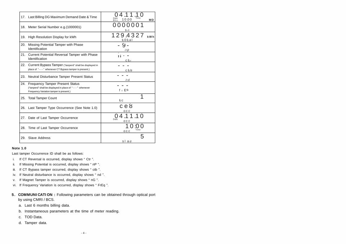
Note 1.0
Last tamper Occurrence ID shall be as follows:
i. If CT Reversal is occurred, display shows “ Ctr ”.
ii. If Missing Potential is occurred, display shows “ nP ”.
iii. If CT Bypass tamper occurred, display shows “ ctb ”.
iv. If Neutral disturbance is occurred, display shows “ nd ”.
v. If Magnet Tamper is occurred, display shows “ nG ”.
vi. If Frequency Variation is occurred, display shows “ FrEq ”.
17. Last Billing DG Maximum Demand Date & Time
18. Meter Serial Number e.g.(1000001)
19. High Resolution Display for kWh
20. Missing Potential Tamper with PhaseIdentification
21. Current Potential Reversal Tamper with PhaseIdentification
22. Current Bypass Tamper (“tanperd” shall be displayed in
place of “ - - - ” whenever CT Bypass tamper is present.)
23. Neutral Disturbance Tamper Present Status
24. Frequency Tamper Present Status(“tanperd” shall be displayed in place of “ - - - ” whenever
Frequency Variation tamper is present.)
25. Total Tamper Count
TimeTOD10.00
04.11.10kVArhMD
kWhDateBILL
MAGNET
-9-kVArhMD
kWhMAGNET
h--DateBILL
MAGNETCOVEROPEN
---MAGNET
COVEROPEN
BCOVEROPEN
0000001MAGNET
COVEROPEN
ffE9
1kVArhMD
kWhMAGNET
129.4327 kWhB
COVEROPEN
MD
sh
hp
cE8
---h8g
---
Ec
26. Last Tamper Type Occurrence (See Note 1.0)
27. Date of Last Tamper Occurrence
28. Time of Last Tamper Occurrence
29. Slave Address
30. CT Ratio
occ
04.11.10DateBILL
MAGNET
10:00MAGNET
COVEROPEN
ce8occ
TimeTOD
E0Eal
occ
5
5-5
cEf
sla8
cEfE

- 3 -
Note : In meter display, following icon shall be displayed to show status of variouscondition as given below.
i. “ R ”, “ Y ”, “ B ” enunciator indicates presence of the respective phase.
ii. “ ” with “ R ”, “ Y ”, “ B ” enunciator blinking indicates respective phase current reverse.
iii. “ MAGNET ” indicates magnetic tamper.iv. Blinking of “ ” icon shall indicate that meter is working in generator
mode.b. Push Button Mode : The parameter in this mode can be viewed by pressingthe push button 2 or 3 to reach to the required parameter. On every press of pushbutton 2 the display shall move 1 parameter forward.On every press of pushbutton 3 the display shall move 1 parameter backward.
kVArhMDCOVEROPENDateBILL
1. LCD Segment Check
2. EEPROM Check
3. Battery Check
4. Total Cumulative Energy kWh
5. Utility Cumulative Energy kWh
6. DG Cumulative Energy kWh
7. Real Date & Time
8. Utility Maximum Demand in kW
9. DG Maximum Demand in kW
10. Last Billing Date & Time
11. Last Billing Total Cumulative Energy kWh
12. Last Billing Utility Total Cumulative Energy kWh
13. Last Billing DG Total Cumulative Energy kWh
14. Last Billing Utility Maximum Demand in kW
15. Last Billing Utility Maximum Demand Date & Time
16. Last Billing DG Maximum Demand in kW
Push Button Parameters Typical Screen Shots
eepkVArhMD
BCOVEROPEN 8g888
kVArhMDB
COVEROPEN 8g888
8ae
TimeTOD10.00
04.11.10kVArhMD
kWhDateBILL
MAGNET
TimeTOD10.00
04.11.10kVArhMD
kWhDateBILL
MAGNET
000129.4kVArhMD
kWhDateBILL
TimeTOD
MAGNETCOVEROPEN
000079.9kVArh
TimeTOD
MAGNETCOVEROPEN
000049.5kVArhMD
kWhB
COVEROPEN
kWh
E0Eal
8g
UELIE9
000100.4 kWhDateBILL
MAGNET
000070.2kVArh
TimeTOD
MAGNETCOVEROPEN
000030.2kVArhMD
kWhB
COVEROPEN
kWh
8g
UELIE9DateBILL
DateBILL
3.260kVArh
TimeTOD
MAGNETCOVEROPEN
kWhUELIE9 MD
3.260kVArh
TimeTOD
MAGNETCOVEROPEN
kWhUELIE9 MD
DateBILL
TimeTOD10.00
04.11.10kVArhMD
kWhDateBILL
MAGNETMD
3.120kVArhMD
kWhB
COVEROPEN 8g MD
3.260 kWhB MD
DateBILL
TimeTOD
MAGNETCOVER OPEN
RYB
E0Eal

1. INSTALLATION
a. Refer to the wiring diagram shown in the manual for installation.
b. Ensure that the cable connections are properly connected as per connectiondiagram.
2. FRONT VIEW / PANEL DESCRIPTION
a. Active Energy (kWh) pulse indication.
b. Push Button 1 : To be used for display in absence of mains supply.
c. Push button 2 : Forward Scroll.
d. Push button 3 : Back Scroll.
e. Optical Communication Port.
f . RS485 Port.
3. TECHNICAL FEATURES3.1 ENERGY REGISTER : The meter measures following energy.
a. Active Energyb. Apparent Energy
3.2 MAXIMUM DEMAND AND MD INTEGRATION PERIODThe demand is monitored during each demand interval of 15/30 minutes(default 30 minutes ) integration and the maximum of these demand is storedas maximum demand along with date and time.
- 1 -
OPERATION AND INSTRUCTION MANUALac, 3 Phase, 4 Wire Dual Source Static Energy Meter
(with
out
MD
Res
et)
- 6 -
DU
AL
SO
UR
CE
//3P
/OC
/BA
R-5
A
8. WIRING DIAGRAM: Wiring Diagram for 3Phase, 4Wire, Dual Source LT CT Operated Energy Meter.
Mains/Generator Selection : When ac 240V (± 20%) is available at P&N terminals
the energy shall be recorded in Generator Energy Register, otherwise it shall be
recorded in Mains Energy Register.
f
b
c
a
e
d
HPL Electric & Power Pvt. Ltd.1/21, Asaf Ali Road, New Delhi - 110 002, Phone: 91-11-23234411, 23234811Fax : 91-11-23232639, E-mail: [email protected], Website: www.hplindia.com(Due to continuous development, specification and features are subject to change without prior notice.)
(NC) (NC)(+) (-)
RS 485 Port
Tx Tx X X
Meter Terminal Block
Mains/Generator Selection
-/5A
-/5A
-/5A
-/5A

3.3 MAXIMUM DEMAND RESETIt is possible to reset the MD is following two ways.
a. CMRIb. Auto Reset : MD shall be reset automatic at 00.00 Hrs on the date for
which billing date is programmed. (for e.g. 1st day of month).
3.4 LOAD SURVEYThe following parameters are provided for load survey with 30 minutesintegration period.
a. Total kWhb. Total kVAhc. Utility kWhd. DG kWh
Load survey is available for last 120 days.
3.5 TOD : The meters have been programmed for 6 TOD slots. The defaultTOD slot timings are as follows :
Slot 1 : 00.00 hrs. to 06.00 hrs.
Slot 2 : 06.00 hrs. to 18.00 hrs.
Slot 3 : 18.00 hrs. to 19.00 hrs.
Slot 4 : 19.00 hrs. to 21.00 hrs.
Slot 5 : 21.00 hrs. to 23.00 hrs.
Slot 6 : 23.00 hrs. to 00.00 hrs.
3.6 POWER ON/OFFPower On/Off event is recorded whenever DG Power goes off for more than5 minutes. Last 20 Power On/Off events are recorded by meter in FIFO basis.
4. DISPLAY DETAILS : As soon as the meter is powered On, it shall show the version number of the firmware.
Then it shall go to first display parameter.
There are two modes of display :a. Auto scroll Modeb. Push Button mode
- 2 -
a. Auto Scroll Mode : Auto scroll mode always displays the following parameter.
Auto Scroll Button Parameters Typical Screen Shots
1. Total Cumulative Energy kWh
2. Utility Cumulative Energy kWh
3. DG Cumulative Energy kWh
000129.4RYB kVArhMD
kWhDateBILL
TimeTOD
MAGNETCOVEROPEN
000079.9RYB kVArh
TimeTOD
MAGNETCOVEROPEN
000049.5RYB kVArhMD
kWhB
COVEROPEN
kWh
E0Eal
8g
UELIE9
- 5 -
7. TECHNICAL CHARACTERISTICS OF METER :
1. Enclosure : Engineering plastic
2. Display : Backlit LCD display
Large digit size 10 mm x 5 mm
3. Protection Index : IP51
4. System : AC 3 Phase, 4 Wire
5. Inputs : Starting Current : 0.1% of Ib
Rated Voltage : 3 x 240V
Current Rating : -/5A
Frequency : 50 Hz ± 5%
Power factor : Zero lag - unity - Zero lead
6. Class of Accuracy : Class 0.5S
7. Application Standard : IS 14697 : 1999
CBIP-88
6. TAMPER THRESHOLDS :
TAMPER EVENT THRESHOLD FOR TAMPER
Occurrence Limit
Occurrence Time
Restoration Time
Restoration Time
Compart –ment No.
1. Missing Potential 20 minute 20 minute
0
a. Voltage in tamper phase
< 20% Vref > 40%Vref
b. Current in tamper phase > 10% Ib Ignored
2. Neutral Disturbance 20 minute 20 minute
a. Voltage in any phase
> 300V Ignored
b. Voltage in all phase Ignored < 300V
3. CT Polarity Reversal 20 minute 20 minute
a. Current in tamper phase
> 5% Ib (In reverse direction)
> 10% Ib (in forward direction)
b. Voltage in Tampered phase
> 20% Vref > 20% Vref
c. Power factor > 0.1 > 0.1
4. CT Bypass 20 minute 20 minute
a. Bypass Current > 30% Ib < 10% Ib
5. Frequency Variation 20 minute 20 minute
a. Freq < 47.5Hz
or > 52.5Hz
Freq > 47.5Hz
or < 52.5Hz
6. Magnet 20 seconds 20 seconds
Under Influence of abnormal Magnetic field
After removal of abnormal Magnetic f ield
Version NumberRYBMAGNET 8888
HISTORYk W h
KVArh MDP -225.XX

18
RYB MAGNET
RYB
kWhMAGNET
- 4 -
5. COMMUNICATION : Following parameters can be obtained through optical portby using CMRI / BCS.
a. Last 6 months billing data.
b. Instantaneous parameters at the time of meter reading.
c. TOD Data.
d. Tamper data.
Note 1.0
Last tamper Occurrence ID shall be as follows:
i. If CT Reversal is occurred, display shows “ Ctr ”.
ii. If Missing Potential is occurred, display shows “ nP ”.
iii. If CT Bypass tamper occurred, display shows “ ctb ”.
iv. If Neutral disturbance is occurred, display shows “ nd ”.
v. If Magnet Tamper is occurred, display shows “ nG ”.
vi. If Frequency Variation is occurred, display shows “ FrEq ”.
17. Last Billing DG Maximum Demand Date & Time
18. Meter Serial Number e.g.(1000001)
19. High Resolution Display for kWh
20. Missing Potential Tamper with PhaseIdentification
21. Current Potential Reversal Tamper with PhaseIdentification
22. Current Bypass Tamper (“tanperd” shall be displayed in
place of “ - - - ” whenever CT Bypass tamper is present.)
23. Neutral Disturbance Tamper Present Status
24. Frequency Tamper Present Status(“tanperd” shall be displayed in place of “ - - - ” whenever
Frequency Variation tamper is present.)
25. Total Tamper Count
TimeTOD10.00
04.11.10kVArhMD
kWhDateBILL
MAGNET
-9-kVArhMD
kWhMAGNET
h--DateBILL
MAGNETCOVEROPEN
---MAGNET
COVEROPEN
BCOVEROPEN
0000001MAGNET
COVEROPEN
ffE9
1kVArhMD
kWhMAGNET
129.4327 kWhB
COVEROPEN
MD
sh
hp
cE8
---h8g
---
Ec
26. Last Tamper Type Occurrence (See Note 1.0)
27. Date of Last Tamper Occurrence
28. Time of Last Tamper Occurrence
29. Slave Address
30. CT Ratio
occ
04.11.10DateBILL
MAGNET
10:00MAGNET
COVEROPEN
ce8occ
TimeTOD
E0Eal
occ
5
5-5
cEf
sla8
cEfE

- 3 -
Note : In meter display, following icon shall be displayed to show status of variouscondition as given below.
i. “ R ”, “ Y ”, “ B ” enunciator indicates presence of the respective phase.
ii. “ ” with “ R ”, “ Y ”, “ B ” enunciator blinking indicates respective phase current reverse.
iii. “ MAGNET ” indicates magnetic tamper.iv. Blinking of “ ” icon shall indicate that meter is working in generator
mode.b. Push Button Mode : The parameter in this mode can be viewed by pressingthe push button 2 or 3 to reach to the required parameter. On every press of pushbutton 2 the display shall move 1 parameter forward.On every press of pushbutton 3 the display shall move 1 parameter backward.
kVArhMDCOVEROPENDateBILL
1. LCD Segment Check
2. EEPROM Check
3. Battery Check
4. Total Cumulative Energy kWh
5. Utility Cumulative Energy kWh
6. DG Cumulative Energy kWh
7. Real Date & Time
8. Utility Maximum Demand in kW
9. DG Maximum Demand in kW
10. Last Billing Date & Time
11. Last Billing Total Cumulative Energy kWh
12. Last Billing Utility Total Cumulative Energy kWh
13. Last Billing DG Total Cumulative Energy kWh
14. Last Billing Utility Maximum Demand in kW
15. Last Billing Utility Maximum Demand Date & Time
16. Last Billing DG Maximum Demand in kW
Push Button Parameters Typical Screen Shots
eepkVArhMD
BCOVEROPEN 8g888
kVArhMDB
COVEROPEN 8g888
8ae
TimeTOD10.00
04.11.10kVArhMD
kWhDateBILL
MAGNET
TimeTOD10.00
04.11.10kVArhMD
kWhDateBILL
MAGNET
000129.4kVArhMD
kWhDateBILL
TimeTOD
MAGNETCOVEROPEN
000079.9kVArh
TimeTOD
MAGNETCOVEROPEN
000049.5kVArhMD
kWhB
COVEROPEN
kWh
E0Eal
8g
UELIE9
000100.4 kWhDateBILL
MAGNET
000070.2kVArh
TimeTOD
MAGNETCOVEROPEN
000030.2kVArhMD
kWhB
COVEROPEN
kWh
8g
UELIE9DateBILL
DateBILL
3.260kVArh
TimeTOD
MAGNETCOVEROPEN
kWhUELIE9 MD
3.260kVArh
TimeTOD
MAGNETCOVEROPEN
kWhUELIE9 MD
DateBILL
TimeTOD10.00
04.11.10kVArhMD
kWhDateBILL
MAGNETMD
3.120kVArhMD
kWhB
COVEROPEN 8g MD
3.260 kWhB MD
DateBILL
TimeTOD
MAGNETCOVER OPEN
RYB
E0Eal

1. INSTALLATION
a. Refer to the wiring diagram shown in the manual for installation.
b. Ensure that the cable connections are properly connected as per connectiondiagram.
2. FRONT VIEW / PANEL DESCRIPTION
a. Active Energy (kWh) pulse indication.
b. Push Button 1 : To be used for display in absence of mains supply.
c. Push button 2 : Forward Scroll.
d. Push button 3 : Back Scroll.
e. Optical Communication Port.
f . RS485 Port.
3. TECHNICAL FEATURES3.1 ENERGY REGISTER : The meter measures following energy.
a. Active Energyb. Apparent Energy
3.2 MAXIMUM DEMAND AND MD INTEGRATION PERIODThe demand is monitored during each demand interval of 15/30 minutes(default 30 minutes ) integration and the maximum of these demand is storedas maximum demand along with date and time.
- 1 -
OPERATION AND INSTRUCTION MANUALac, 3 Phase, 4 Wire Dual Source Static Energy Meter
(with
out
MD
Res
et)
- 6 -
DU
AL
SO
UR
CE
/3P
/OC
/10-
60A
HPL ELECTRIC & POWER PVT. LTD.1/21, Asaf Ali Road, New Delhi -110002, Phone : 91-11-23234411, 23234811Fax: 91-11-23232639, Email: [email protected], Website: www.hplindia.comDue to continuous development, specification and features are subject to change without prior notice.
d
e
a
b
c
f
8. WIRING DIAGRAM :
Wiring Diagram for ac, 3Phase, 4Wire, Dual Source Whole CurrentStatic Energy Meter
Mains/Generator Selection : When dc 24V (± 20%) is available at P&N terminals
the energy shall be recorded in Generator Energy Register, otherwise it shall be
recorded in Mains Energy Register.
R
Y
B
N
(24V, dc inGenerator Mode)
Tx(+)
Tx(-)
X(NC)
X(NC)
RS485 Port
RS485 Port
Meter Terminal Block
1(In) 1(Out) 2(In) 2(Out) 3(In) 3(Out) N(In) N(Out)P
N
P
N RS485

3.3 MAXIMUM DEMAND RESETIt is possible to reset the MD is following three ways.
a. CMRIb. Auto Reset : MD shall be reset automatic at 00.00Hrs on the date for
which billing date is programmed. (for e.g. 1st day of month).
3.4 LOAD SURVEYThe following parameters are provided for load survey with 30 minutesintegration period.
a. Total kWhb. Total kVAhc. Utility kWhd. DG kWh
Load survey is available for last 120 days.
3.5 TOD : The meters have been programmed for 6 TOD slots. The defaultTOD slot timings are as follows :
Slot 1 : 00.00 hrs. to 06.00 hrs.
Slot 2 : 06.00 hrs. to 18.00 hrs.
Slot 3 : 18.00 hrs. to 19.00 hrs.
Slot 4 : 19.00 hrs. to 21.00 hrs.
Slot 5 : 21.00 hrs. to 23.00 hrs.
Slot 6 : 23.00 hrs. to 00.00 hrs.
3.6 POWER ON/OFFPower On/Off event is recorded when ever DG Power goes off for more than5 minutes. Last 20 Power On/Off events are recorded by meter in FIFO basis.
4. DISPLAY DETAILS : As soon as the meter is powered On, it shall show theversion number of the firmware.
Then it shall go to first display parameter.
There are two modes of display :a. Auto scroll Modeb. Push Button mode
- 2 -
a. Auto Scroll Mode : Auto scroll mode always displays the following parameter.
Auto Scroll Button Parameters Typical Screen Shots
1. Total Cumulative Energy kWh
2. Utility Cumulative Energy kWh
3. DG Cumulative Energy kWh
000129.4RYB kVArhMD
kWhDateBILL
TimeTOD
MAGNETCOVEROPEN
000079.9RYB kVArh
TimeTOD
MAGNETCOVEROPEN
000049.5RYB kVArhMD
kWhB
COVEROPEN
kWh
E0Eal
8g
UELIE9
- 5 -
7. TECHNICAL CHARACTERISTICS OF METER :
1. Enclosure : Engineering plastic
2. Display : Backlit LCD display
Large digit size 10 mm x 5 mm
3. Protection Index : IP51
4. System : AC 3 Phase, 4 Wire
5. Inputs : Starting Current : 0.2% of Ib
Rated Voltage : 3 x 240V
Current Rating : 10-60A
Frequency : 50 Hz ± 5%
Power factor : Zero lag - unity - Zero lead
6. Class of Accuracy : Class 1.0
7. Application Standard : IS 13779 : 1999
CBIP-88
6. TAMPER THRESHOLDS :
THRESHOLD FOR TAMPER TAMPER EVENT Occurrence
Limit Occurrence
Time Restoration
Time Restoration
Time Compart –ment No.
1. Missing Potential 20 minute 20 minute
a. Voltage in tamper phase
< 20% Vref > 40%Vref
b. Current in tamper phase
> 10% Ib Ignored
2. Neutral Disturbance 20 minute 20 minute
a. Voltage in any phase
> 300V Ignored
b. Voltage in all phase Ignored < 300V
3. CT Polarity Reversal 20 minute 20 minute
a. Current in tamper phase
> 5% Ib (In reverse direction)
> 10% Ib (in forward direction)
b. Voltage in Tampered phase
> 20% Vref > 20% Vref
c. Power factor > 0.1 > 0.1
4. CT Bypass 20 minute 20 minute
a. Bypass Current > 30% Ib < 10% Ib
5. Frequency Variation 20 minute 20 minute
a. Freq < 47.5Hz
or > 52.5Hz
Freq > 47.5Hz
or < 52.5Hz
0
6. Magnet 20 seconds 20 seconds
Under Influence of abnormal Magnetic field
After removal of abnormal Magnetic field
Version NumberRYBMAGNET 8888
HISTORYk W h
KVArh MDP -255.XX
18
RYB MAGNET
RYB
kWhMAGNET
- 4 -
5. COMMUNICATION : Following parameters can be obtained through optical portby using CMRI / BCS.
a. Last 6 months billing data.
b. Instantaneous parameters at the time of meter reading.
c. TOD Data.
d. Tamper data.
Note 1.0
Last tamper Occurrence ID shall be as follows:
i. If CT Reversal is occurred, display shows “ Ctr ”.
ii. If Missing Potential is occurred, display shows “ nP ”.
iii. If CT Bypass tamper occurred, display shows “ ctb ”.
iv. If Neutral disturbance is occurred, display shows “ nd ”.
v. If Magnet Tamper is occurred, display shows “ nG ”.
vi. If Frequency Variation is occurred, display shows “ FrEq ”.
17. Last Billing DG Maximum Demand Date & Time
18. Meter Serial Number e.g.(1000001)
19. High Resolution Display for kWh
20. Missing Potential Tamper with PhaseIdentification
21. Current Potential Reversal Tamper with PhaseIdentification
22. Current Bypass Tamper (“tanperd” shall be displayed in
place of “ - - - ” whenever CT Bypass tamper is present.)
23. Neutral Disturbance Tamper Present Status
24. Frequency Tamper Present Status(“tanperd” shall be displayed in place of “ - - - ” whenever
Frequency Variation tamper is present.)
25. Total Tamper Count
TimeTOD10.00
04.11.10kVArhMD
kWhDateBILL
MAGNET
-9-kVArhMD
kWhMAGNET
h--DateBILL
MAGNETCOVEROPEN
---MAGNET
COVEROPEN
BCOVEROPEN
0000001MAGNET
COVEROPEN
ffE9
1kVArhMD
kWhMAGNET
129.4327 kWhB
COVEROPEN
MD
sh
hp
cEf
cE8
---h8g
---
Ec
26. Last Tamper Type Occurrence (See Note 1.0)
27. Date of Last Tamper Occurrence
28. Time of Last Tamper Occurrence
29. Slave Address
occ
04.11.10DateBILL
MAGNET
10:00MAGNET
COVEROPEN
5B
COVEROPEN
ce8occ
sla8
TimeTOD
E0Eal
occ

MDDateBILLCOVEROPEN
- 3 -
Note : In meter display, following icon shall be displayed to show status of variouscondition as given below.
i. “ R ”, “ Y ”, “ B ” enunciator indicates presence of the respective phase.
ii. “ ” with “ R ”, “ Y ”, “ B ” enunciator blinking indicates respective phase current reverse.
iii. “ MAGNET ” indicates magnetic tamper.iv. Blinking of “ ” icon shall indicate that meter is working in generator
mode.b. Push Button Mode : The parameter in this mode can be viewed by pressingthe push button 2 or 3 to reach to the required parameter. On every press of pushbutton 2 the display shall move 1 parameter forward.On every press of pushbutton 3 the display shall move 1 parameter backward.
kVArhMDCOVEROPENDateBILL
1. LCD Segment Check
2. EEPROM Check
3. Battery Check
4. Total Cumulative Energy kWh
5. Utility Cumulative Energy kWh
6. DG Cumulative Energy kWh
7. Real Date & Time
8. Utility Maximum Demand in kW
9. DG Maximum Demand in kW
10. Last Billing Date & Time
11. Last Billing Total Cumulative Energy kWh
12. Last Billing Utility Total Cumulative Energy kWh
13. Last Billing DG Total Cumulative Energy kWh
14. Last Billing Utility Maximum Demand in kW
15. Last Billing Utility Maximum Demand Date & Time
16. Last Billing DG Maximum Demand in kW
Push Button Parameters Typical Screen Shots
eepkVArhMD
BCOVEROPEN 8g888
kVArhMDB
COVEROPEN 8g888
8ae
TimeTOD10.00
04.11.10kVArhMD
kWhDateBILL
MAGNET
TimeTOD10.00
04.11.10kVArhMD
kWhDateBILL
MAGNET
000129.4kVArhMD
kWhDateBILL
TimeTOD
MAGNETCOVEROPEN
000079.9kVArh
TimeTOD
MAGNETCOVEROPEN
000049.5kVArhMD
kWhB
COVEROPEN
kWh
E0Eal
8g
UELIE9
000100.4 kWhDateBILL
MAGNET
000070.2kVArh
TimeTOD
MAGNETCOVEROPEN
000030.2kVArhMD
kWhB
COVEROPEN
kWh
8g
UELIE9DateBILL
DateBILL
3.260kVArh
TimeTOD
MAGNETCOVEROPEN
kWhUELIE9 MD
3.260kVArh
TimeTOD
MAGNETCOVEROPEN
kWhUELIE9 MD
DateBILL
TimeTOD10.00
04.11.10kVArhMD
kWhDateBILL
MAGNETMD
3.120kVArhMD
kWhB
COVEROPEN 8g MD
3.260 kWhB MD
DateBILL
TimeTOD
MAGNETCOVER OPEN
RYB
E0Eal

3.3 MAXIMUM DEMAND RESETIt is possible to reset the MD is following three ways.
a. CMRIb. Auto Reset : MD shall be reset automatic at 00.00Hrs on the date for
which billing date is programmed. (for e.g. 1st day of month).
3.4 LOAD SURVEYThe following parameters are provided for load survey with 30 minutesintegration period.
a. Total kWhb. Total kVAhc. Utility kWhd. DG kWh
Load survey is available for last 120 days.
3.5 TOD : The meters have been programmed for 6 TOD slots. The defaultTOD slot timings are as follows :
Slot 1 : 00.00 hrs. to 06.00 hrs.
Slot 2 : 06.00 hrs. to 18.00 hrs.
Slot 3 : 18.00 hrs. to 19.00 hrs.
Slot 4 : 19.00 hrs. to 21.00 hrs.
Slot 5 : 21.00 hrs. to 23.00 hrs.
Slot 6 : 23.00 hrs. to 00.00 hrs.
3.6 POWER ON/OFFPower On/Off event is recorded when ever DG Power goes off for more than5 minutes. Last 20 Power On/Off events are recorded by meter in FIFO basis.
4. DISPLAY DETAILS : As soon as the meter is powered On, it shall show theversion number of the firmware.
Then it shall go to first display parameter.
There are two modes of display :a. Auto scroll Modeb. Push Button mode
- 2 -
a. Auto Scroll Mode : Auto scroll mode always displays the following parameter.
Auto Scroll Button Parameters Typical Screen Shots
1. Total Cumulative Energy kWh
2. Utility Cumulative Energy kWh
3. DG Cumulative Energy kWh
000129.4RYB kVArhMD
kWhDateBILL
TimeTOD
MAGNETCOVEROPEN
000079.9RYB kVArh
TimeTOD
MAGNETCOVEROPEN
000049.5RYB kVArhMD
kWhB
COVEROPEN
kWh
E0Eal
8g
UELIE9
- 5 -
7. TECHNICAL CHARACTERISTICS OF METER :
1. Enclosure : Engineering plastic
2. Display : Backlit LCD display
Large digit size 10 mm x 5 mm
3. Protection Index : IP51
4. System : AC 3 Phase, 4 Wire
5. Inputs : Starting Current : 0.2% of Ib
Rated Voltage : 3 x 240V
Current Rating : 10-60A
Frequency : 50 Hz ± 5%
Power factor : Zero lag - unity - Zero lead
6. Class of Accuracy : Class 1.0
7. Application Standard : IS 13779 : 1999
CBIP-88
6. TAMPER THRESHOLDS :
THRESHOLD FOR TAMPER TAMPER EVENT Occurrence
Limit Occurrence
Time Restoration
Time Restoration
Time Compart –ment No.
1. Missing Potential 20 minute 20 minute
a. Voltage in tamper phase
< 20% Vref > 40%Vref
b. Current in tamper phase
> 10% Ib Ignored
2. Neutral Disturbance 20 minute 20 minute
a. Voltage in any phase
> 300V Ignored
b. Voltage in all phase Ignored < 300V
3. CT Polarity Reversal 20 minute 20 minute
a. Current in tamper phase
> 5% Ib (In reverse direction)
> 10% Ib (in forward direction)
b. Voltage in Tampered phase
> 20% Vref > 20% Vref
c. Power factor > 0.1 > 0.1
4. CT Bypass 20 minute 20 minute
a. Bypass Current > 30% Ib < 10% Ib
5. Frequency Variation 20 minute 20 minute
a. Freq < 47.5Hz
or > 52.5Hz
Freq > 47.5Hz
or < 52.5Hz
0
6. Magnet 20 seconds 20 seconds
Under Influence of abnormal Magnetic field
After removal of abnormal Magnetic field
Version NumberRYBMAGNET 8888
HISTORYk W h
KVArh MDP -210.XX

18
RYB MAGNET
RYB
kWhMAGNET
- 4 -
5. COMMUNICATION : Following parameters can be obtained through optical portby using CMRI / BCS.
a. Last 6 months billing data.
b. Instantaneous parameters at the time of meter reading.
c. TOD Data.
d. Tamper data.
Note 1.0
Last tamper Occurrence ID shall be as follows:
i. If CT Reversal is occurred, display shows “ Ctr ”.
ii. If Missing Potential is occurred, display shows “ nP ”.
iii. If CT Bypass tamper occurred, display shows “ ctb ”.
iv. If Neutral disturbance is occurred, display shows “ nd ”.
v. If Magnet Tamper is occurred, display shows “ nG ”.
vi. If Frequency Variation is occurred, display shows “ FrEq ”.
17. Last Billing DG Maximum Demand Date & Time
18. Meter Serial Number e.g.(1000001)
19. High Resolution Display for kWh
20. Missing Potential Tamper with PhaseIdentification
21. Current Potential Reversal Tamper with PhaseIdentification
22. Current Bypass Tamper (“tanperd” shall be displayed in
place of “ - - - ” whenever CT Bypass tamper is present.)
23. Neutral Disturbance Tamper Present Status
24. Frequency Tamper Present Status(“tanperd” shall be displayed in place of “ - - - ” whenever
Frequency Variation tamper is present.)
25. Total Tamper Count
TimeTOD10.00
04.11.10kVArhMD
kWhDateBILL
MAGNET
-9-kVArhMD
kWhMAGNET
h--DateBILL
MAGNETCOVEROPEN
---MAGNET
COVEROPEN
BCOVEROPEN
0000001MAGNET
COVEROPEN
ffE9
1kVArhMD
kWhMAGNET
129.4327 kWhB
COVEROPEN
MD
sh
hp
cEf
cE8
---h8g
---
Ec
26. Last Tamper Type Occurrence (See Note 1.0)
27. Date of Last Tamper Occurrence
28. Time of Last Tamper Occurrence
29. Slave Address
occ
04.11.10DateBILL
MAGNET
10:00MAGNET
COVEROPEN
5B
COVEROPEN
ce8occ
sla8
TimeTOD
E0Eal
occ

MDDateBILLCOVEROPEN
- 3 -
Note : In meter display, following icon shall be displayed to show status of variouscondition as given below.
i. “ R ”, “ Y ”, “ B ” enunciator indicates presence of the respective phase.
ii. “ ” with “ R ”, “ Y ”, “ B ” enunciator blinking indicates respective phase current reverse.
iii. “ MAGNET ” indicates magnetic tamper.iv. Blinking of “ ” icon shall indicate that meter is working in generator
mode.b. Push Button Mode : The parameter in this mode can be viewed by pressingthe push button 2 or 3 to reach to the required parameter. On every press of pushbutton 2 the display shall move 1 parameter forward.On every press of pushbutton 3 the display shall move 1 parameter backward.
kVArhMDCOVEROPENDateBILL
1. LCD Segment Check
2. EEPROM Check
3. Battery Check
4. Total Cumulative Energy kWh
5. Utility Cumulative Energy kWh
6. DG Cumulative Energy kWh
7. Real Date & Time
8. Utility Maximum Demand in kW
9. DG Maximum Demand in kW
10. Last Billing Date & Time
11. Last Billing Total Cumulative Energy kWh
12. Last Billing Utility Total Cumulative Energy kWh
13. Last Billing DG Total Cumulative Energy kWh
14. Last Billing Utility Maximum Demand in kW
15. Last Billing Utility Maximum Demand Date & Time
16. Last Billing DG Maximum Demand in kW
Push Button Parameters Typical Screen Shots
eepkVArhMD
BCOVEROPEN 8g888
kVArhMDB
COVEROPEN 8g888
8ae
TimeTOD10.00
04.11.10kVArhMD
kWhDateBILL
MAGNET
TimeTOD10.00
04.11.10kVArhMD
kWhDateBILL
MAGNET
000129.4kVArhMD
kWhDateBILL
TimeTOD
MAGNETCOVEROPEN
000079.9kVArh
TimeTOD
MAGNETCOVEROPEN
000049.5kVArhMD
kWhB
COVEROPEN
kWh
E0Eal
8g
UELIE9
000100.4 kWhDateBILL
MAGNET
000070.2kVArh
TimeTOD
MAGNETCOVEROPEN
000030.2kVArhMD
kWhB
COVEROPEN
kWh
8g
UELIE9DateBILL
DateBILL
3.260kVArh
TimeTOD
MAGNETCOVEROPEN
kWhUELIE9 MD
3.260kVArh
TimeTOD
MAGNETCOVEROPEN
kWhUELIE9 MD
DateBILL
TimeTOD10.00
04.11.10kVArhMD
kWhDateBILL
MAGNETMD
3.120kVArhMD
kWhB
COVEROPEN 8g MD
3.260 kWhB MD
DateBILL
TimeTOD
MAGNETCOVER OPEN
RYB
E0Eal


![6 . Wiring Diagram Legacy/Service Manual/1996 LEGACY RH… · 6-3 [D601] WIRING DIAGRAM 6 . Wiring Diagram 6 . Wiring Diagram Battery current 1 . POWER SUPPLY ROUTING Current from](https://img.pdfslide.us/doc/110x75/6058f70ca8a7ee39513c5dc6/6-wiring-legacyservice-manual1996-legacy-rh-6-3-d601-wiring-diagram-6-.jpg)
![5. Wiring Diagram - Subaru Forester. Wiring Diagram A: POWER SUPPLY ROUTING SU01-04A 12 6-3 [D5A0] WIRING DIAGRAM 5. Wiring Diagram SU01-04B 13 WIRING DIAGRAM [D5A0] 6-3 5. Wiring](https://img.pdfslide.us/doc/110x75/5aa205fe7f8b9a1f6d8cac3f/5-wiring-diagram-subaru-wiring-diagram-a-power-supply-routing-su01-04a-12.jpg)
![6. Wiring Diagram - · PDF fileFB-11 Radio FB-12 Cigarette lighter FB-13 Remote control rearview mirror switch FB-14 ... WIRING DIAGRAM 6. Wiring Diagram. MEMO: 21 WIRING DIAGRAM [D6A2]](https://img.pdfslide.us/doc/110x75/5ab1b6427f8b9a00728cab2a/6-wiring-diagram-radio-fb-12-cigarette-lighter-fb-13-remote-control-rearview.jpg)

![6. Wiring Diagram - weidefamily.net coil Transmission control module ... WIRING DIAGRAM 6. Wiring Diagram. MEMO: 21 WIRING DIAGRAM ... 76 6-3 [D6R2] WIRING DIAGRAM 6](https://img.pdfslide.us/doc/110x75/5aa0cc3b7f8b9a62178ea5e7/6-wiring-diagram-coil-transmission-control-module-wiring-diagram-6-wiring.jpg)