Embed Size (px)
Citation preview

OPTIMUS 2004
2003-2004 Autonomous Vehicle Team
of Virginia Tech
TEAM MEMBERS: Andrew Bacha Ankur Naik

2
Required Faculty Advisor Statement
I certify that the software redesign of Optimus has been significant. The two graduate students responsible for this effort, Ankur Naik and Andrew Bacha, performed this work as part of a computer vision course and as extracurricular project. Signed,
Charles F. Reinholtz, Professor of Mechanical Engineering
1 – INTRODUCTION
Virginia Tech’s Optimus was a successful entry in the 2003 Intelligent Ground Vehicle
Competition, winning first place in the Autonomous Challenge and second place in the Design,
Navigation, and Follow the leader competitions. The Virginia Tech Autonomous Vehicle Team
(AVT) is proud to bring a refined version of Optimus with new software back to the IGVC in
2004. The vehicle name was derived from the popular television cartoon series Transformers.
In this cartoon, robot characters change their form to overcome challenges. Optimus was initially
designed with a transforming mobility platform, supporting both 3 and 4 wheel configurations.
After a year of testing, configuration of Optimus is now fixed with 2 drive wheels and caster.
Optimus was designed with several key goals in mind, including serviceability,
upgradeability, and originality. The chassis of Optimus gives easy access to all vehicle
components, including the electrical system, power system, computational hardware, and
sensors. With a solid platform already in place, the bulk of improvements to Optimus come from
a redesign in software.
The design of Optimus broke new ground for the Virginia Tech Autonomous Vehicle
Team by changing software development from Visual C++ to LabVIEW by National
Instruments. The power and easy to use interface of LabVIEW was a large factor in the success
of Optimus. This year, the bulk of redesign work was dedicated to improving software. The
sensor interfaces from the previous year as well as LabVIEW’s camera calibration tools allowed
the team to focus on improving navigation algorithms.

3
2 – DESIGN PROCESS
2.1 – Design Methods
The design of Optimus was guided by the mission statement of building an autonomous
vehicle that could compete favorably in the Intelligent Ground Vehicle Competition, reflect well
on Virginia Tech, and be marketable outside of the university. To achieve the goals set forth in
this mission statement, the team followed the design process described in Product Design and
Development (Ulrich and Eppinger, 2000), shown in Figure 2.1. The steps in this process are
iterative, meaning that one or more steps may be repeated until satisfactory results are obtained.
Figure 2.1 – The design process used for Optimus
In past years, Virginia Tech’s teams have committed the bulk of development time to
build new vehicles or make drastic structural changes to existing vehicles. This strategy delayed
software testing until vehicles were ready for driving. To ensure there would always be a running
vehicle for testing software, it was decided that Optimus would only receive minor changes to its
frame and electrical systems. As a result, the physical changes to Optimus were directed at
increasing the stability and ruggedness of the vehicle, but keeping Optimus as the perfect
environment for software testing and development. Any radical ideas and innovations in vehicle
structure would be applied to our two new vehicles.
Reflecting on the performance of Optimus at the IGVC as well as further testing done at
Virginia Tech, new needs were established and the design process was repeated to further refine
the vehicle. To reduce the maintenance of the frame, the drive configuration of Optimus is now
permanently 2 drive wheels and a rear caster. Last year, Optimus had the ability to change from
two-wheel to four-wheel drive mode. Optimus also had to be updated to support a new DGPS
and digital compass.
Identify Customer
Needs Establish Target Specifications Generate
Product Concepts
Test Product
Concept(s)
Set Final
Specifications
Plan Downstream Development
Mission Statement
Development
Plan

4
The software used last year was reviewed to direct the development of the current
software. At the 2003 IGVC Autonomous Challenge, Optimus failed by driving through a space
in a dashed line. To address this failure, a major goal of the development of Autonomous
Challenge software was to be able to identify lines and detect their orientation and placement.
With more detailed analysis of lines, it became easier to detect when a line became dashed as
well as strengthening previous line detection algorithms.
2.2 – Team Organization
With software as the focus of team Optimus, both team members were dedicated to
developing software. Andrew Bacha and Ankur Naik are both masters students enrolled in the
graduate mechanical engineering program at Virginia Tech. Both students are returning team
Optimus members. With their experience on the team last year, they were also responsible for
the frame changes as well as well guiding the development of Virginia Tech’s other vehicles:
Johnny 5 and Gemini. Andrew and Ankur spent approximately 200 hours on the redesign and
development of Optimus.
3 – VEHICLE DESIGN AND CONSTRUCTION
The vehicle frame was designed to provide a flexible and stable platform to facilitate
research related to autonomous vehicles. The 24-inch by 22-inch by 15-inch space inside the
vehicle shell allows internal components to be cleanly arranged. The frame is constructed from
welded steel tubing and steel angle. A lightweight fiberglass shell covers the frame, protecting
internal components from the weather. Optimus weighs 220 pounds when fully outfitted for
competition.
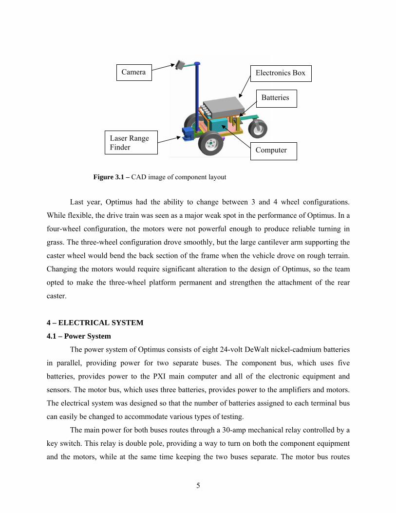
The modular design of the frame makes Optimus easy to maintain. The layout of each
major component is shown in Figure 3.1. The electronic systems of the vehicle are inside a
single electronics box that can be easily removed. The camera, GPS antennae, and laser range
finder are mounted on a single mast in front of the vehicle shell. This allows the shell to be
removed without disturbing these components or disconnecting wires. An equipment rack on top
of the shell carries the payload and is adjustable to support payloads of different shapes and
sizes.
5
Figure 3.1 – CAD image of component layout
Last year, Optimus had the ability to change between 3 and 4 wheel configurations.
While flexible, the drive train was seen as a major weak spot in the performance of Optimus. In a
four-wheel configuration, the motors were not powerful enough to produce reliable turning in
grass. The three-wheel configuration drove smoothly, but the large cantilever arm supporting the
caster wheel would bend the back section of the frame when the vehicle drove on rough terrain.
Changing the motors would require significant alteration to the design of Optimus, so the team
opted to make the three-wheel platform permanent and strengthen the attachment of the rear
caster.
4 – ELECTRICAL SYSTEM
4.1 – Power System
The power system of Optimus consists of eight 24-volt DeWalt nickel-cadmium batteries
in parallel, providing power for two separate buses. The component bus, which uses five
batteries, provides power to the PXI main computer and all of the electronic equipment and
sensors. The motor bus, which uses three batteries, provides power to the amplifiers and motors.
The electrical system was designed so that the number of batteries assigned to each terminal bus
can easily be changed to accommodate various types of testing.
The main power for both buses routes through a 30-amp mechanical relay controlled by a
key switch. This relay is double pole, providing a way to turn on both the component equipment
and the motors, while at the same time keeping the two buses separate. The motor bus routes
Electronics Box
Computer
Camera
Laser Range Finder
Batteries

6
through a second relay controlled by the e-stop system and continues on to power the amps and
motors. The component bus routes straight to a connection board and from there powers the
computer and all sensors. To power the various onboard devices that require less than 24 volts, a
DC to DC converter is used to break the 24-volt component bus into 5 and 12 volts.
One of the most important features of the battery system on Optimus is that the batteries
are hot-swappable. All eight batteries can be monitored for charge status using LabVIEW
software. When a weak battery is detected, the hot swap battery circuit allows it to be replaced
while maintaining component and motor power, thus preventing electrical surges to sensitive
equipment and eliminating the need to restart devices.
4.2 – Control System
The control system of Optimus is based on a PXI-7344 National Instruments motion
controller. The controller is a single module located inside one of the chassis slots, directly
integrated with the main computer. In addition to four axis controls, the controller has several
digital I/O pins. The control and sensor system is shown in Figure 4.1.
Figure 4.1 – Control and sensor system

7
To actuate the motors, the motor controller produces two analog signals proportional to
the desired left and right motor speeds. The signals are passed to a set of Advanced Motion
Control servo motor amplifiers, which send a corresponding current of 0 to 25 amps to drive the
motors. Encoders integrated into the motors send a signal back to the motor controller to
facilitate speed control, thus completing the closed-loop control system.
A switch on the back panel of the electrical box determines whether Optimus operates in
manual or autonomous mode. In manual operation, the computer uses a Radio Controlled (R/C)
receiver output to control the motors. In autonomous operation, the computer controls the motors
directly through its autonomous navigation code.
In manual mode, the R/C system uses a basic stamp processor to interpret the signals
from two receiver channels. The basic stamp is connected to a digital potentiometer, which
outputs 0-5 volts according to the signal received. This voltage is then read and interpreted by
the computer, which outputs the corresponding speed signal to the motor amplifiers. If no signal
is received, this is interpreted as an E-stop. In the case of an E-stop, the stamp triggers an E-stop
circuit-board relay. This E-stop circuit-board relay is connected directly in line with the main E-
stop relay, which cuts power to the motors.
4.3 – Sensors
Optimus uses four sensors to obtain external data: a Canon ES75 8mm camcorder, a
SICK LMS-200 laser range finder (LRF), a PNI TCM2-20 digital compass, and a Novatel
Propack-LB Differential GPS. The camcorder is used to find lines during the Autonomous
Challenge. Optimus uses a LRF to detect all obstacles. The LRF scans a 180° plane in front of
the vehicle, detecting all obstacles within a specified range up to 80 meters. The digital compass
is used to determine the vehicle’s heading during the Autonomous and Navigation Challenges.
The compass is a three-axis, tilt-compensated compass, eliminating the need for the compass to
be oriented horizontally. The DGPS receiver is the primary means of determining vehicle
location during the Navigation Challenge.
Video images are captured by the camera, converted to digital format by a National
Instruments frame grabber, and sent to the navigation software. The LRF, compass and DGPS
are connected directly to the PXI computer by a serial RS-232 connection.
8
Figure 5.1 – Autonomous challenge flow diagram
5 – SOFTWARE
5.1 -National Instruments LabVIEW
Once again Software development took priority in the re-design of Optimus. Given our
previous success with using the National Instruments Labview programming language, we
decided to use it again for the Optimus 2004 software. Labview is a graphical programming
language that uses a block diagram approach to programming. Labview has all the capabilities of
other high level programming languages such as C++. The built in functions of Labview and its
add on packages as well as its simple to use Graphical User Interface (GUI) tools dramatically
shortens development time. Labview also has an extremely short learning curve. Even novice
programmers can begin developing complex programs within weeks.
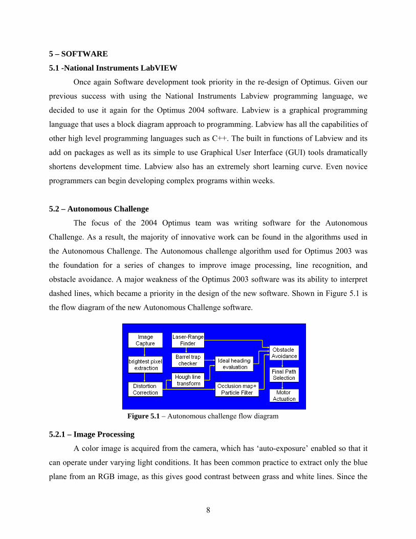
5.2 – Autonomous Challenge
The focus of the 2004 Optimus team was writing software for the Autonomous
Challenge. As a result, the majority of innovative work can be found in the algorithms used in
the Autonomous Challenge. The Autonomous challenge algorithm used for Optimus 2003 was
the foundation for a series of changes to improve image processing, line recognition, and
obstacle avoidance. A major weakness of the Optimus 2003 software was its ability to interpret
dashed lines, which became a priority in the design of the new software. Shown in Figure 5.1 is
the flow diagram of the new Autonomous Challenge software.
5.2.1 – Image Processing
A color image is acquired from the camera, which has ‘auto-exposure’ enabled so that it
can operate under varying light conditions. It has been common practice to extract only the blue
plane from an RGB image, as this gives good contrast between grass and white lines. Since the

9
grass is expected to contain mostly green color, the green color plane is subtracted from a
heavier weighted blue color plane, reducing the noise from light colored grass. This is a
computationally simple operation that will increase the quality of the vision data, making bad
line detections less likely. Figure 5.2 compares the new extracted image results to the
conventional blue plane extraction.
Figure 5.2 – Images extracted using a combination of color planes (left) versus the blue plane (right)
5.2.2 – Line Recognition
The image is first split vertically into two halves. The Brightest Pixel Extraction code
extracts the coordinates and intensity of the brightest pixel on every row for both halves of the
image. The extracted points are sent to distortion correction code that converts the image plane
coordinates to real world coordinates using the rules of perspective transformation. These points
are then plotted onto a new image called an Occlusion Map that is thresheld and run through a
Particle Filter to reject noise. The resulting points are passed to Hough Line Transform code
which fits a line to points within a given range in front of the vehicle for the left side and right
side of the image.
The Hough line transform is a well known method of fitting a line to points. The Hough
line transform is processor intensive but, unlike a least squares line fit, it is not affected by noise
or line orientation. Only the points within a short horizontal strip in front of the vehicle are used.
This allows us to approximate the curved path with a straight line, which saves processing time.
An example of the image processing is shown in Figure 5.3. On the left of Figure 5.3 is the
original image and on the right is the occlusion map with the Hough line fits shown in yellow.
10
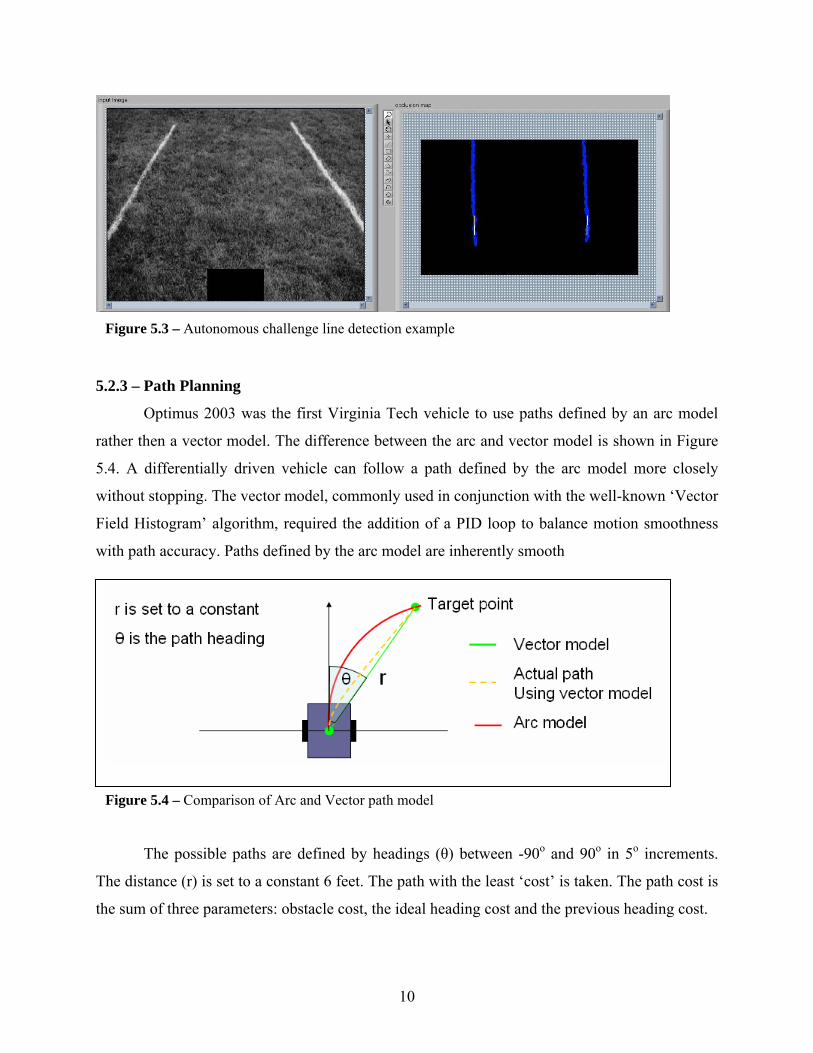
5.2.3 – Path Planning
Optimus 2003 was the first Virginia Tech vehicle to use paths defined by an arc model
rather then a vector model. The difference between the arc and vector model is shown in Figure
5.4. A differentially driven vehicle can follow a path defined by the arc model more closely
without stopping. The vector model, commonly used in conjunction with the well-known ‘Vector
Field Histogram’ algorithm, required the addition of a PID loop to balance motion smoothness
with path accuracy. Paths defined by the arc model are inherently smooth
The possible paths are defined by headings (θ) between -90o and 90o in 5o increments.
The distance (r) is set to a constant 6 feet. The path with the least ‘cost’ is taken. The path cost is
the sum of three parameters: obstacle cost, the ideal heading cost and the previous heading cost.
Figure 5.3 – Autonomous challenge line detection example
Figure 5.4 – Comparison of Arc and Vector path model

11
Figure 5.5 – Obstacle Avoidance Method
The obstacle cost is the value of
the most intense obstacle in the path. This
is calculated by the Obstacle Avoidance
code. Every obstacle from the laser range
finder and the occlusion map that is within
a 6 foot range is checked against every
path as shown in Figure 5.5. An obstacle
crosses a path if Rinner < Robject + Ro and
Router > Robject - Ro.
The ideal heading cost is a function
that increases exponentially with the
path’s deviation from the ideal heading. The ideal heading is determined by the Ideal Heading
Evaluation code. For the case when a line is detected on both the right and left side of the image,
the ideal heading is toward a point equidistant between the two lines. If the laser range finder
detects a barrel trap further ahead of the vehicle, this target point will be shifted 3 feet to the
opposite side of the course. In the event that only one line is detected, the ideal heading will be
parallel to and 5 feet away from the detected line. If no lines are detected the ideal heading will
be straight.
The previous heading cost is calculated by a function that increases exponentially with
the path’s deviation from the previous heading. This cost parameter typically much smaller than
the other two costs. It is designed to prevent drastic changes in direction. This adds a damping
effect to keep the vehicle from oscillating.
In the case that the least costly path still has an impassible obstacle in its way, the vehicle
will take a zero radius turn in the direction of the previous heading. This occurs when an
unusually sharp turn is encountered.
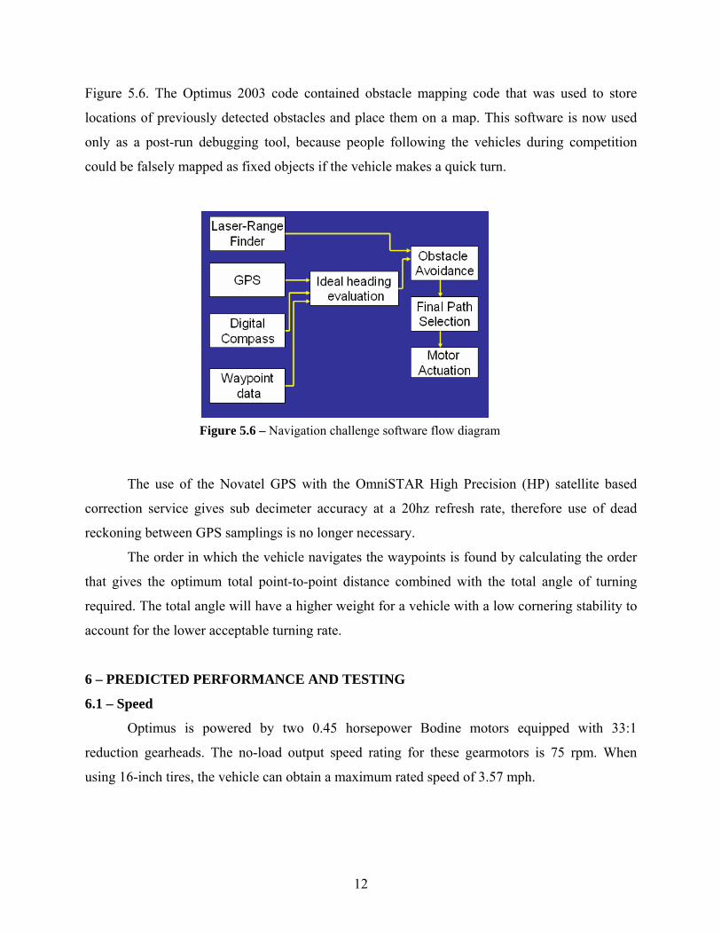
5.3 – Navigation challenge
The code for the navigation challenge uses the same obstacle avoidance and path
selection method as the autonomous challenge. The ideal heading is simply the direction to the
next waypoint, which is found using the GPS and the compass. Only the laser range finder is
used for obstacle avoidance. The flow diagram for the Navigation Challenge code is shown in
12
Figure 5.6 – Navigation challenge software flow diagram
Figure 5.6. The Optimus 2003 code contained obstacle mapping code that was used to store
locations of previously detected obstacles and place them on a map. This software is now used
only as a post-run debugging tool, because people following the vehicles during competition
could be falsely mapped as fixed objects if the vehicle makes a quick turn.
The use of the Novatel GPS with the OmniSTAR High Precision (HP) satellite based
correction service gives sub decimeter accuracy at a 20hz refresh rate, therefore use of dead
reckoning between GPS samplings is no longer necessary.
The order in which the vehicle navigates the waypoints is found by calculating the order
that gives the optimum total point-to-point distance combined with the total angle of turning
required. The total angle will have a higher weight for a vehicle with a low cornering stability to
account for the lower acceptable turning rate.
6 – PREDICTED PERFORMANCE AND TESTING
6.1 – Speed
Optimus is powered by two 0.45 horsepower Bodine motors equipped with 33:1
reduction gearheads. The no-load output speed rating for these gearmotors is 75 rpm. When
using 16-inch tires, the vehicle can obtain a maximum rated speed of 3.57 mph.

13
6.2 – Ramp Climbing Ability
While the largest ramp incline specified by the IGVC is a 15% grade (8.5 degrees), a 15-
degree incline was used in ramp-climbing calculations to account for the possibility of the ramp
being on a slope or discontinuities, such as uneven plywood panels, in the ramp surface. With
16-inch wheels, Optimus requires 228 lb-in of torque per motor to maintain its position on the
ramp. The motors on Optimus output 269 lb-in of torque, allowing the vehicle to advance up the
ramp. During testing Optimus was able to climb a ramp made with IGVC dimensions starting
from a complete stop.
6.3 – Battery Life
The Dewalt batteries used on Optimus are rated at 2.4 amp-hours each. During testing, it
was found best to use five batteries for the component bus and three for the motor bus. This
provides approximately 30 minutes of run time for the computer and electronic components, and
20 minutes of actual run time for the motors.
6.4 – Distance at which Obstacles are Detected
An important factor in the Autonomous Challenge is the distance at which Optimus can
detect obstacles. The large field of view of the camera, along with image processing, provides
Optimus with the ability to detect potholes, sand traps, and course lines as far as 12 feet ahead.
The LRF has a range of up to 260 feet, but the current navigation algorithm ignores objects more
than 40 feet away. This range is sufficient to see the barrel trap and move the vehicle to the
correct side of the course before it is seen by the camera.
6.5 – Reaction Times
During the Autonomous Challenge and the Navigation Challenge, the software refreshes at 7.5 Hz
and 20 Hz respectively. The sensors are able to collect and transmit data faster than the software refresh,
leaving processing as the limiting reaction factor. Depending on when the obstacle is detected by the
sensor, it could take between 0.13 and 0.26 seconds from the time an obstacle is sensed to when a signal
is sent to the motor for the Autonomous Challenge. With the Navigation Challenge’s simpler software,
the time is shortened to between 0.05 and 0.1 seconds. Once the motors have received the motion
command, it takes 0.2 seconds to change speed by 1 mph, enough to alter the vehicle’s path. This yields a
maximum possible reaction time of 0.46 seconds. At a speed of 5 mph, the 0.46 reaction time means that
the vehicle will move 3.4 feet before reacting to an obstacle. This distance is less than the sensing range,
giving Optimus the necessary time to react to a detected obstacle.

14
6.6 – Navigation Accuracy
Testing shows Optimus can consistently navigate to GPS waypoints to within less than
one meter. This can be directly attributed to high accuracy sensors. The DGPS is configured to
receive the OmniSTAR HP service, providing a horizontal accuracy of 15 centimeters 99% of
the time. Since GPS heading is unavailable or unreliable at low speeds, a digital compass is used
for accurate heading readings. The PNI TCM2-20 digital compass has an accuracy of 0.2
degrees.
7 – OTHER DESIGN ISSUES
7.1 – Safety
Safety was the most important concern in all aspects of the design, fabrication, and
operation of Optimus. Three modes of stopping Optimus in case of an emergency were
implemented into the vehicle design. The first mode is a manual E-stop button, located at the rear
of the vehicle, which opens a relay disconnecting power to each amplifier, removing power from
the motors. In addition, the motor brakes are automatically engaged when motor power is lost,
stopping the vehicle in less than one foot from 5 mph. The second mode is a remote E-stop
feature programmed onto a wireless remote joystick. This remote E-stop is independent of the
software, and works up to 50 feet away. The third E-stop mode is controlled via software using a
laptop computer connected to the PXI main computer using the Remote Desktop feature of
Windows XP. Software detects when any of the E-stop modes have been activated, and no power
is sent to the motors.

15
7.2 – Costs
Table 7.1 shows a cost breakdown for the components used to build Optimus.
Table 7.1 – Cost breakdown for Optimus
Components Retail Cost Cost to TeamPXI 1000B Chassis $2,795 $0PXI 8175 Controller $3,695 $0PXI 7344 Motion Controller $1,695 $0PXI 6025E I/O Connector $895 $0(2) PXI 1411 Frame Grabber $2,190 $0PXI 8422 Serial Expansion Card $495 $0Novatel Propack-LB DGPS $7,995 $2,995PNI TCM2-20 digital compass $699 $0Sick LMS-200 LRF $3,400 $0Wireless Router $80 $0Cannon 8mm Camera $220 $220(8) Dewalt 24V Battery $880 $0(2) Bodine Motors $1,200 $0(2) AMC Amplifier $1,120 $560(3) Wheels $75 $75Frame $200 $200Shell $150 $150Electrical Components $400 $400Total $28,184 $4,600
8 - CONCLUSION
Created for the 2003 IGVC, Optimus was designed to be rugged and reliable while
having easy to access to components. The 2003 Optimus team succeeded in their design goals,
providing a proven base vehicle for innovative software development. We hope that Optimus
2004 will use its enhanced obstacle avoidance and line detecting algorithms to improve upon a
successful debut year and make Optimus a top contender in the 12th annual IGVC.