Embed Size (px)
Citation preview
Medtronic Confidentialreference_R02
8840_ENfc.fm 3/29/04UC20010xxxx EN xxx releaseSize inches (mm)/CTC
221438002 Rev X
N’VISION™
Clinician Programmer
Technical Manual
Rx Only
8840

Medtronic Confidentialreference_R02
8840_ENfc.fm 3/29/04UC20010xxxx EN xxx releaseSize inches (mm)/CTC
221438002 Rev X
2R
MEDTRONIC CONFIDENTIAL REF_R18
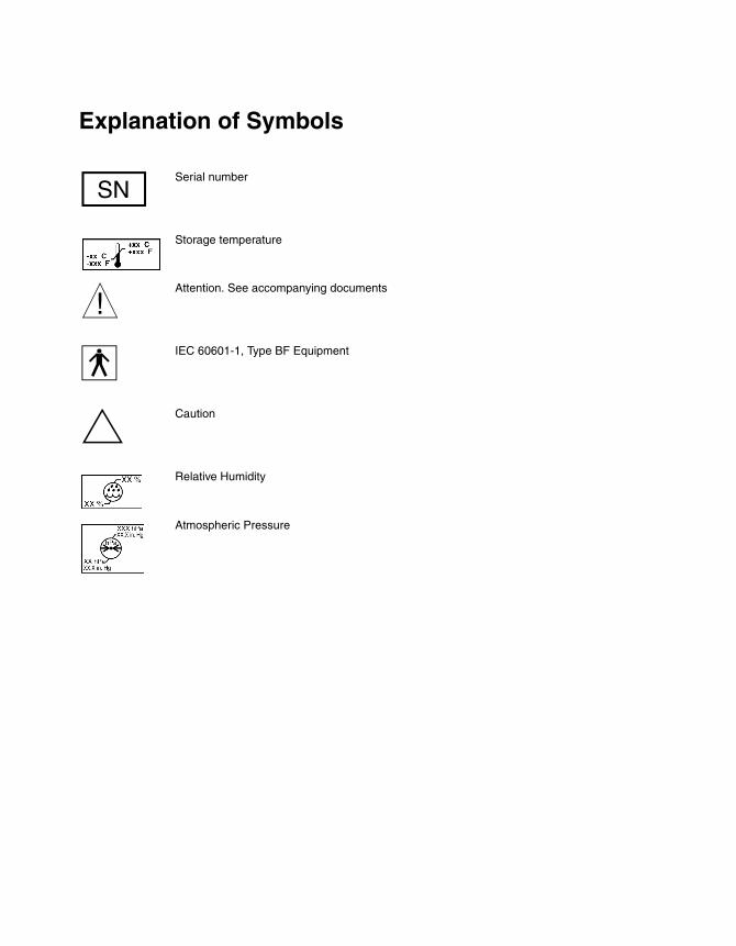
Explanation of Symbols
nSerial number
Storage temperature
wAttention. See accompanying documents
yIEC 60601-1, Type BF Equipment
#Caution
Relative Humidity
Atmospheric Pressure
21438002ev X
Size inches (mm)/CTCUC20010xxxx EN xxx releaseDefine as desired

MEDTRONIC CONFIDENTIAL REF_R18
Medtronic is a registered trademark of Medtronic, Inc. N’Vision is a trademark of Medtronic, Inc.
221438002Rev X
Size inches (mm)/CTCUC20010xxxx EN xxx releaseDefine as desired
How to Use This Guide
2
MEDTRONIC CONFIDENTIAL REFRNCEN.BCV
How to Use This Guide
About the Model 8840 N’Vision Clinician Programmer Guide
This guide presents information for users of the N’Vision Clinician Programmer:
■ Programmer overview
■ Programmer description
■ Programmer use
■ Programmer maintenance
■ Programmer troubleshooting
■ Programmer specifications
■ Glossary
Medtronic N’Vision Clinician Technical Manual iii
21438002 Rev XSize inches (mm)/CTCUC20010xxxx EN xxx releaseDefine as desired

How to Use This Guide
MEDTRONIC CONFIDENTIAL REFRNCEN.BCV
iv Medtronic N’Vision Clinician Technical Manual
221438002 Rev XSize inches (mm)/CTCUC20010xxxx EN xxx releaseDefine as desired
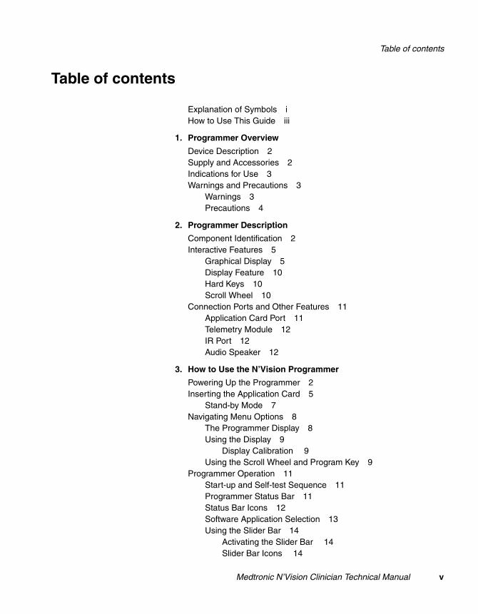
Table of contents
2
MEDTRONIC CONFIDENTIAL REFRNCEN.BCV
Table of contents
Explanation of Symbols iHow to Use This Guide iii
1. Programmer Overview
Device Description 2Supply and Accessories 2Indications for Use 3Warnings and Precautions 3
Warnings 3Precautions 4
2. Programmer Description
Component Identification 2Interactive Features 5
Graphical Display 5Display Feature 10Hard Keys 10Scroll Wheel 10
Connection Ports and Other Features 11Application Card Port 11Telemetry Module 12IR Port 12Audio Speaker 12
3. How to Use the N’Vision Programmer
Powering Up the Programmer 2Inserting the Application Card 5
Stand-by Mode 7Navigating Menu Options 8
The Programmer Display 8Using the Display 9
Display Calibration 9Using the Scroll Wheel and Program Key 9
Programmer Operation 11Start-up and Self-test Sequence 11Programmer Status Bar 11Status Bar Icons 12Software Application Selection 13Using the Slider Bar 14
Activating the Slider Bar 14Slider Bar Icons 14
Medtronic N’Vision Clinician Technical Manual v
21438002 Rev XSize inches (mm)/CTCUC20010xxxx EN xxx releaseDefine as desired
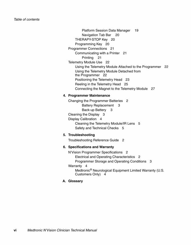
Table of contents
MEDTRONIC CONFIDENTIAL REFRNCEN.BCV
Platform Session Data Manager 19Navigation Tab Bar 20
THERAPY-STOP Key 20Programming Key 20
Programmer Connections 21Communicating with a Printer 21
Printing 21Telemetry Module Use 22
Using the Telemetry Module Attached to the Programmer 22Using the Telemetry Module Detached from the Programmer 22Positioning the Telemetry Head 23Reeling in the Telemetry Head 25Connecting the Magnet to the Telemetry Module 27
4. Programmer Maintenance
Changing the Programmer Batteries 2Battery Replacement 3Back-up Battery 3
Cleaning the Display 3Display Calibration 4
Cleaning the Telemetry Module/IR Lens 5Safety and Technical Checks 5
5. Troubleshooting
Troubleshooting Reference Guide 2
6. Specifications and Warranty
N’Vision Programmer Specifications 2Electrical and Operating Characteristics 2Programmer Storage and Operating Conditions 3
Warranty 4Medtronic® Neurological Equipment Limited Warranty (U.S. Customers Only) 4
A. Glossary
vi Medtronic N’Vision Clinician Technical Manual
221438002 Rev XSize inches (mm)/CTCUC20010xxxx EN xxx releaseDefine as desired
Medtronic N’Vision C
221438002Rev X
MEDTRONIC CONFIDENTIAL REF_R18
1
Programmer Overview 1Device Description 1-2
Supply and Accessories 1-2
Indications for Use 1-3
Warnings and Precautions 1-3
linician Technical Manual 1-1
Size inches (mm)/CTCUC20010xxxx EN xxx releaseDefine as desired
Programmer OverviewDevice Description
MEDTRONIC CONFIDENTIAL REF_R18
Device Description
The Model 8840 N’Vision Clinician Programmer is a small, portable device that offers a single programming platform for Medtronic Neurological implantable therapy devices. The programmer is equipped with a touchscreen display for data entry, telemetry head for device programming, and an infrared port through which communications can be established with compatible printers.
A therapy application card that contains application-specific software is supplied separately.
Supply and Accessories
The following accessories are used in conjunction with the N’Vision Programmer:
■ therapy software on an application card (supplied separately)■ a compatible printer (optional)■ a magnet (required for programming SynchroMed and
SynchroMed EL Pumps)
1-2 Medtronic N’Vision Clinician Technical Manual
221438002Rev X
Size inches (mm)/CTCUC20010xxxx EN xxx releaseDefine as desired
Programmer OverviewIndications for Use
2R
MEDTRONIC CONFIDENTIAL REF_R18
Indications for Use
The N’Vision Programmer is indicated for use with Medtronic Neurological therapies and devices as provided on Medtronic application cards. Refer to specific programming guides to determine card compatibility.
Warnings and Precautions
Warnings
■ Refer to the appropriate implant/device manual for instructions on specific therapy applications and a complete listing of warnings, precautions, contraindications and instructions for use for applications.
■ The N’Vision Programmer can only be used to program Medtronic Neurological devices that correspond with therapy application software on the application card within the programmer.
■ Use only fresh batteries (four “AA” alkaline batteries).■ Do not immerse the N’Vision Programmer in water or other
fluids. Do not expose the programmer to excessive amounts of water or other fluids. This may damage the programmer.
■ Do not connect the N’Vision Programmer to any equipment not specifically listed in this technical manual. Connection to non-specified equipment may result in damage to the programmer or patient injury.
■ Do not use the N’Vision Programmer if it is damaged.■ Peripheral equipment connected to the N’Vision Programmer
must be certified according to the respective IEC standards (e.g., IEC 950 for data processing equipment and IEC 60601 for medical equipment). Furthermore, the system formed by the N’Vision Programmer and any connected peripherals must comply with the requirements of IEC 60601-1-1, safety requirements for medical electrical systems. Such compliance is the responsibility of the person who connects the peripheral. If in doubt, consult the technical services department or your local representative.
For all peripherals certified to IEC 950, it is the responsibility of the user to keep the peripheral at least 2 meters from the patient. This will satisfy the requirements of IEC 60601-1-1.
Medtronic N’Vision Clinician Technical Manual 1-3
21438002ev X
Size inches (mm)/CTCUC20010xxxx EN xxx releaseDefine as desired
Programmer OverviewWarnings and Precautions
MEDTRONIC CONFIDENTIAL REF_R18
■ When using the programmer in a sterile field, place the programmer and programming head in a sterile bag. The programmer is not sterile and cannot be sterilized.
■ The magnet is for use with Medtronic SynchroMed and SynchroMed EL pumps only. Remove the magnet before using the N’Vision Programmer with Medtronic neurostimulators.
■ Return devices for disposal to Medtronic when the devices are no longer functional.
■ If the display is inactive, inadvertent programming may occur. ■ If the display is not working, do not use the N’Vision
Programmer. Return the device to Medtronic for repair.
Precautions
■ Power failures during programmer use will reinitialize the programmer, and application state data will be lost.
■ Do not remove the application card while a therapy is active, because these circumstances may cause programming operations to cease.
■ Do not drop the device, because the display may break, causing injury to the user.
■ Telemetry failures will result in loss of communication between the programmer and the device. To ensure that telemetry is established and maintained, keep the telemetry head as close as practical to the implantable device. Do not move the telemetry head once telemetry has been established.
■ Do not insert nonMedtronic, generic compact flash cards into the N’Vision Programmer.
■ The N’Vision Programmer is not certified for use in the presence of a flammable anesthetic mixture with air or with oxygen or nitrous oxide. The consequences of using the N’Vision Programmer near flammable atmospheres are unknown.
1-4 Medtronic N’Vision Clinician Technical Manual
221438002Rev X
Size inches (mm)/CTCUC20010xxxx EN xxx releaseDefine as desired
Programmer OverviewWarnings and Precautions
2R
MEDTRONIC CONFIDENTIAL REF_R18
■ Medtronic neurostimulators controlled by the N’Vision Programmer may affect the operation of other implanted devices, such as cardiac pacemakers and ICDs. Physical proximity of implanted neurostimulators to other implanted devices may cause sensing problems and inappropriate responses by these other implanted devices. If the patient requires concurrent implantable pacemaker and/or defibrillation therapy, evaluation of any potential interference problems and careful programming of each system may be necessary to optimize the patient’s benefit from each device.
■ The THERAPY-STOP function ( ) does not operate unless an application card is in place in the programmer and a therapy has been selected.
■ Do not use the N’Vision Programmer or Application Card if they were transported or stored at temperatures above or below the specified temperature range of -40° – 149 °F (-40° – 65 °C). Allow the equipment to stabilize to a temperature within the operating range of -48° – 105 °F (10° – 40 °C) before using it to program.
Medtronic N’Vision Clinician Technical Manual 1-5
21438002ev X
Size inches (mm)/CTCUC20010xxxx EN xxx releaseDefine as desired

Programmer OverviewWarnings and Precautions
MEDTRONIC CONFIDENTIAL REF_R18
1-6 Medtronic N’Vision Clinician Technical Manual
221438002Rev X
Size inches (mm)/CTCUC20010xxxx EN xxx releaseDefine as desired
Medtronic N’Vision C
221438002Rev X
MEDTRONIC CONFIDENTIAL REF_R18
2
Programmer Description 2Component Identification 2-2
Interactive Features 2-5
Connection Ports and Other Features 2-11
linician Technical Manual 2-1
Size inches (mm)/CTCUC20010xxxx EN xxx releaseDefine as desired
Programmer DescriptionComponent Identification
MEDTRONIC CONFIDENTIAL REF_R18
Component Identification
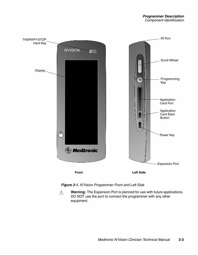
The front of the Model 8840 N’Vision Clinician Programmer is equipped with a touchscreen display and a THERAPY-STOP “hard key” (Figure 2-1). The left side of the programmer includes an application card port, two “hard” keys (to initiate power or programming functions), a scroll wheel used during programming, and a button used to eject application cards from the programmer. An infrared transceiver (IR port) is located at the top of the programmer.
Note: Serial number information for the N’Vision Programmer is displayed:
■ inside the programmer battery compartment■ on the programmer Information Screen (refer to Figure 3-11)
2-2 Medtronic N’Vision Clinician Technical Manual
221438002Rev X
Size inches (mm)/CTCUC20010xxxx EN xxx releaseDefine as desired
Programmer DescriptionComponent Identification
2R
MEDTRONIC CONFIDENTIAL REF_R18
Figure 2-1. N’Vision Programmer Front and Left Side
w Warning: The Expansion Port is planned for use with future applications. DO NOT use the port to connect the programmer with any other equipment.
IR Port
Scroll Wheel
Programming Key
Application Card Port
Application Card Eject Button
Power Key
THERAPY-STOPHard Key
Display
Front Left Side
Expansion Port
Medtronic N’Vision Clinician Technical Manual 2-3
21438002ev X
Size inches (mm)/CTCUC20010xxxx EN xxx releaseDefine as desired
Programmer DescriptionComponent Identification
MEDTRONIC CONFIDENTIAL REF_R18
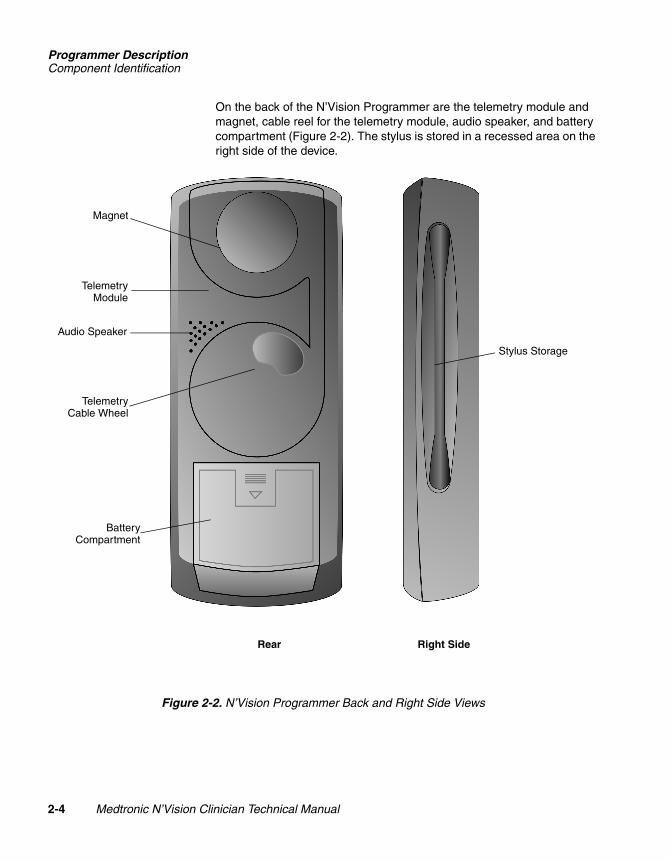
On the back of the N’Vision Programmer are the telemetry module and magnet, cable reel for the telemetry module, audio speaker, and battery compartment (Figure 2-2). The stylus is stored in a recessed area on the right side of the device.
Figure 2-2. N’Vision Programmer Back and Right Side Views
Stylus Storage
Right SideRear
Magnet
TelemetryModule
TelemetryCable Wheel
Audio Speaker
BatteryCompartment
2-4 Medtronic N’Vision Clinician Technical Manual
221438002Rev X
Size inches (mm)/CTCUC20010xxxx EN xxx releaseDefine as desired
Programmer DescriptionInteractive Features
2R
MEDTRONIC CONFIDENTIAL REF_R18
Interactive Features
Graphical Display
The touchscreen of the programmer displays text and graphical messages that guide the user through all programmer functions. The display is divided into five sectors:
■ Programmer status bar
■ Title bar
■ Application tabs
■ Primary application area
■ Secondary application area
The significance of each sector is unique.
Icons have been placed on these sectors, and these icons represent either access to status information (“inactive” icons) or links to another function within the program (“active” icons).
Inactive icons may appear as faded or outlined graphics. Active icons appear as selectable “buttons” on the screen.
Medtronic N’Vision Clinician Technical Manual 2-5
21438002ev X
Size inches (mm)/CTCUC20010xxxx EN xxx releaseDefine as desired
Programmer DescriptionInteractive Features
MEDTRONIC CONFIDENTIAL REF_R18
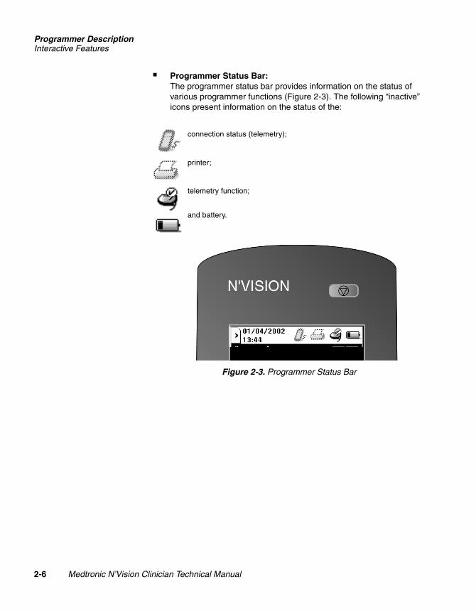
■ Programmer Status Bar:The programmer status bar provides information on the status of various programmer functions (Figure 2-3). The following “inactive” icons present information on the status of the:
Figure 2-3. Programmer Status Bar
connection status (telemetry);
printer;
telemetry function;
and battery.
2-6 Medtronic N’Vision Clinician Technical Manual
221438002Rev X
Size inches (mm)/CTCUC20010xxxx EN xxx releaseDefine as desired
Programmer DescriptionInteractive Features
2R
MEDTRONIC CONFIDENTIAL REF_R18
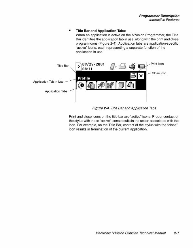
■ Title Bar and Application Tabs:When an application is active on the N’Vision Programmer, the Title Bar identifies the application tab in use, along with the print and close program icons (Figure 2-4). Application tabs are application-specific “active” icons, each representing a separate function of the application in use.
Figure 2-4. Title Bar and Application Tabs
Print and close icons on the title bar are “active” icons. Proper contact of the stylus with these “active” icons results in the action associated with the icon. For example, on the Title Bar, contact of the stylus with the “close” icon results in termination of the current application.
Title Bar
Application Tabs
Print Icon
Close Icon
Application Tab in Use
Medtronic N’Vision Clinician Technical Manual 2-7
21438002ev X
Size inches (mm)/CTCUC20010xxxx EN xxx releaseDefine as desired
Programmer DescriptionInteractive Features
MEDTRONIC CONFIDENTIAL REF_R18
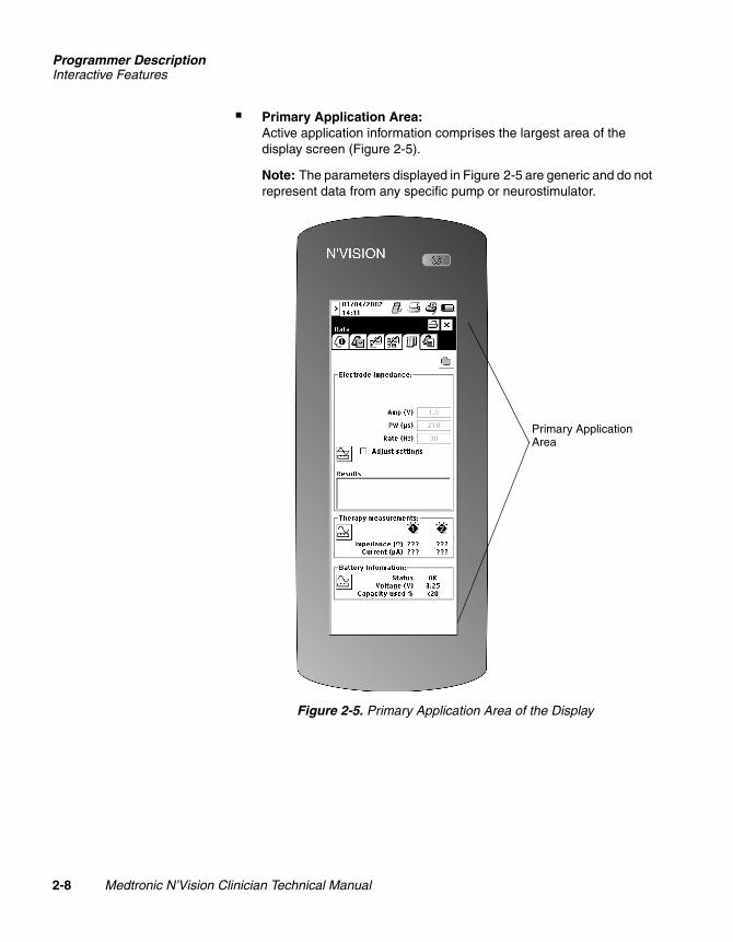
■ Primary Application Area:Active application information comprises the largest area of the display screen (Figure 2-5).
Note: The parameters displayed in Figure 2-5 are generic and do not represent data from any specific pump or neurostimulator.
Figure 2-5. Primary Application Area of the Display
Primary Application Area
2-8 Medtronic N’Vision Clinician Technical Manual
221438002Rev X
Size inches (mm)/CTCUC20010xxxx EN xxx releaseDefine as desired
Programmer DescriptionInteractive Features
2R
MEDTRONIC CONFIDENTIAL REF_R18
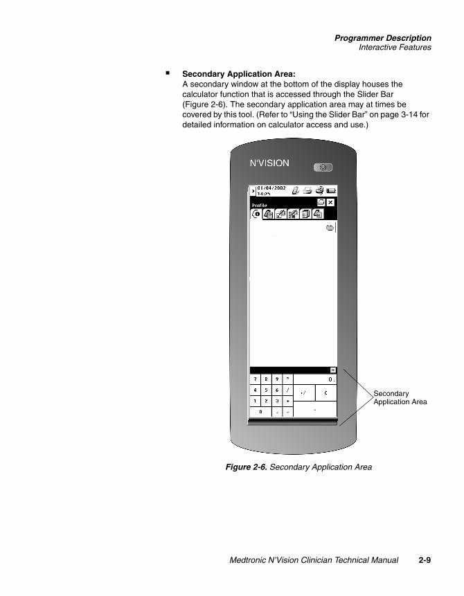
■ Secondary Application Area:A secondary window at the bottom of the display houses the calculator function that is accessed through the Slider Bar (Figure 2-6). The secondary application area may at times be covered by this tool. (Refer to “Using the Slider Bar” on page 3-14 for detailed information on calculator access and use.)
Figure 2-6. Secondary Application Area
Secondary Application Area
Medtronic N’Vision Clinician Technical Manual 2-9
21438002ev X
Size inches (mm)/CTCUC20010xxxx EN xxx releaseDefine as desired
Programmer DescriptionInteractive Features
MEDTRONIC CONFIDENTIAL REF_R18
Display Feature
The entire area of the display is functional. Each operative sector of the display can be activated by stylus (provided with the N’Vision Programmer) or fingertip touch. All therapy applications available for use with this device can be selected through use of the display, as can programmer parameters such as date, time, and language.
# Caution: If stylus contact with the display results in a different function, action, or therapy than expected, the display must be calibrated. Display calibration is described in detail in “Chapter 4, Programmer Maintenance.”
Note: Do not use sharp objects (i.e., pencils, pens, paperclips) on the display. Use only the stylus provided with the programmer, or your fingertip.
Hard Keys
Three “hard keys” on the N’Vision Programmer correspond with three specific functions: power key, application of power; programming key, programming; and THERAPY-STOP key, immediate stop-therapy functions. Figure 2-1 shows the location of the keys on the programmer.
Scroll Wheel
The scroll wheel is positioned on the left side panel of the programmer (Figure 2-1). The scroll wheel is used when programmer input requires continuous variation of parameters or when the user needs to operate the programmer with one hand. The scroll wheel spins in both directions (up/down) for parameter variation and depresses inward for parameter selection. Scroll wheel functions are application specific and may vary from one therapy to another. Refer to the appropriate programming guide for more detailed information on the use of the scroll wheel.
2-10 Medtronic N’Vision Clinician Technical Manual
221438002Rev X
Size inches (mm)/CTCUC20010xxxx EN xxx releaseDefine as desired
Programmer DescriptionConnection Ports and Other Features
2R
MEDTRONIC CONFIDENTIAL REF_R18
Connection Ports and Other Features
Application Card Port
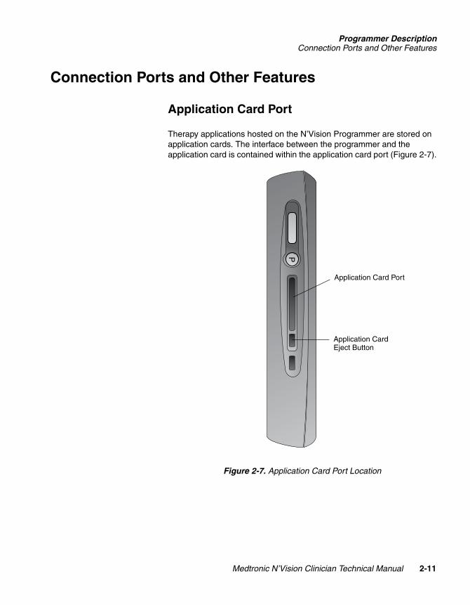
Therapy applications hosted on the N’Vision Programmer are stored on application cards. The interface between the programmer and the application card is contained within the application card port (Figure 2-7).
Figure 2-7. Application Card Port Location
P
Application Card Port
Application Card Eject Button
Medtronic N’Vision Clinician Technical Manual 2-11
21438002ev X
Size inches (mm)/CTCUC20010xxxx EN xxx releaseDefine as desired
Programmer DescriptionConnection Ports and Other Features
MEDTRONIC CONFIDENTIAL REF_R18
Telemetry Module
The N’Vision Programmer is comprised of a base module and a telemetry module. The telemetry module is attached to the base module by a 1-meter long cable that can be retracted onto a spool in the back of the base module (Figure 2-2). The telemetry module can be used while extended or while housed on the programmer.
IR Port
An IR port located on the top of the N’Vision Programmer (Figure 2-1) allows the device to communicate with IR-capable printers without physical connections.
Audio Speaker
An audio speaker located in the back of the N’Vision Programmer provides audible signals to the user during various programming conditions and events (Figure 2-2). Successful completion of an event, failed event completion, and system errors will be identified by a series of unique tones:
■ Success (two tones in rapid succession, the second a higher pitch than the first)
■ Error (two tones in rapid succession, the second a lower pitch than the first)
■ Alert (two tones in rapid succession, both the same pitch)
■ Failure (five flat tones in rapid succession)
The volume of these tones is user adjustable, and they can be turned off.
Additionally, successful contact of the stylus with an icon on the display is confirmed with the sound of a click. This sound can be turned off, but the volume is not adjustable.
2-12 Medtronic N’Vision Clinician Technical Manual
221438002Rev X
Size inches (mm)/CTCUC20010xxxx EN xxx releaseDefine as desired
Medtronic N’Vision C
221438002Rev X
MEDTRONIC CONFIDENTIAL REF_R18
3
How to Use the N’Vision Programmer 3The first few pages of this chapter present basic information on use of the N’Vision Programmer. Specific operational instructions begin on page 3-11.
Powering Up the Programmer 3-2
Inserting the Application Card 3-5
Navigating Menu Options 3-8
Programmer Operation 3-11
Programmer Connections 3-21
Telemetry Module Use 3-22
linician Technical Manual 3-1
Size inches (mm)/CTCUC20010xxxx EN xxx releaseDefine as desired
How to Use the N’Vision ProgrammerPowering Up the Programmer
MEDTRONIC CONFIDENTIAL REF_R18
Powering Up the Programmer
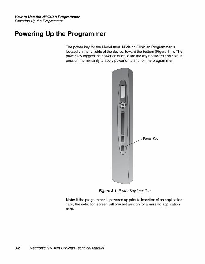
The power key for the Model 8840 N’Vision Clinician Programmer is located on the left side of the device, toward the bottom (Figure 3-1). The power key toggles the power on or off. Slide the key backward and hold in position momentarily to apply power or to shut off the programmer.
Figure 3-1. Power Key Location
Note: If the programmer is powered up prior to insertion of an application card, the selection screen will present an icon for a missing application card.
P
Power Key
3-2 Medtronic N’Vision Clinician Technical Manual
221438002Rev X
Size inches (mm)/CTCUC20010xxxx EN xxx releaseDefine as desired
How to Use the N’Vision ProgrammerPowering Up the Programmer
2R
MEDTRONIC CONFIDENTIAL REF_R18
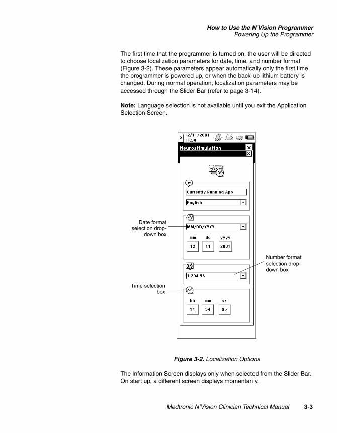
The first time that the programmer is turned on, the user will be directed to choose localization parameters for date, time, and number format (Figure 3-2). These parameters appear automatically only the first time the programmer is powered up, or when the back-up lithium battery is changed. During normal operation, localization parameters may be accessed through the Slider Bar (refer to page 3-14).
Note: Language selection is not available until you exit the Application Selection Screen.
Figure 3-2. Localization Options
The Information Screen displays only when selected from the Slider Bar. On start up, a different screen displays momentarily.
Number format selection drop-down box
Date formatselection drop-
down box
Time selectionbox
Medtronic N’Vision Clinician Technical Manual 3-3
21438002ev X
Size inches (mm)/CTCUC20010xxxx EN xxx releaseDefine as desired
How to Use the N’Vision ProgrammerPowering Up the Programmer
MEDTRONIC CONFIDENTIAL REF_R18
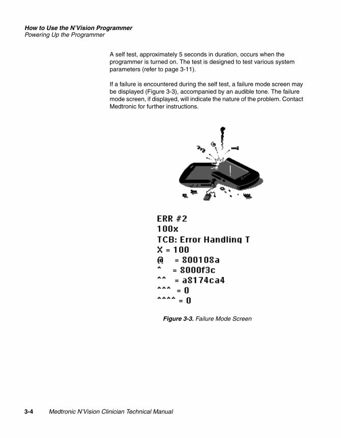
A self test, approximately 5 seconds in duration, occurs when the programmer is turned on. The test is designed to test various system parameters (refer to page 3-11).
If a failure is encountered during the self test, a failure mode screen may be displayed (Figure 3-3), accompanied by an audible tone. The failure mode screen, if displayed, will indicate the nature of the problem. Contact Medtronic for further instructions.
Figure 3-3. Failure Mode Screen
3-4 Medtronic N’Vision Clinician Technical Manual
221438002Rev X
Size inches (mm)/CTCUC20010xxxx EN xxx releaseDefine as desired
How to Use the N’Vision ProgrammerInserting the Application Card
2R
MEDTRONIC CONFIDENTIAL REF_R18
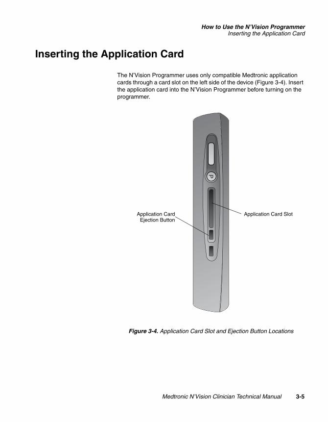
Inserting the Application Card
The N’Vision Programmer uses only compatible Medtronic application cards through a card slot on the left side of the device (Figure 3-4). Insert the application card into the N’Vision Programmer before turning on the programmer.
Figure 3-4. Application Card Slot and Ejection Button Locations
P
Application Card SlotApplication CardEjection Button
Medtronic N’Vision Clinician Technical Manual 3-5
21438002ev X
Size inches (mm)/CTCUC20010xxxx EN xxx releaseDefine as desired
How to Use the N’Vision ProgrammerInserting the Application Card
MEDTRONIC CONFIDENTIAL REF_R18
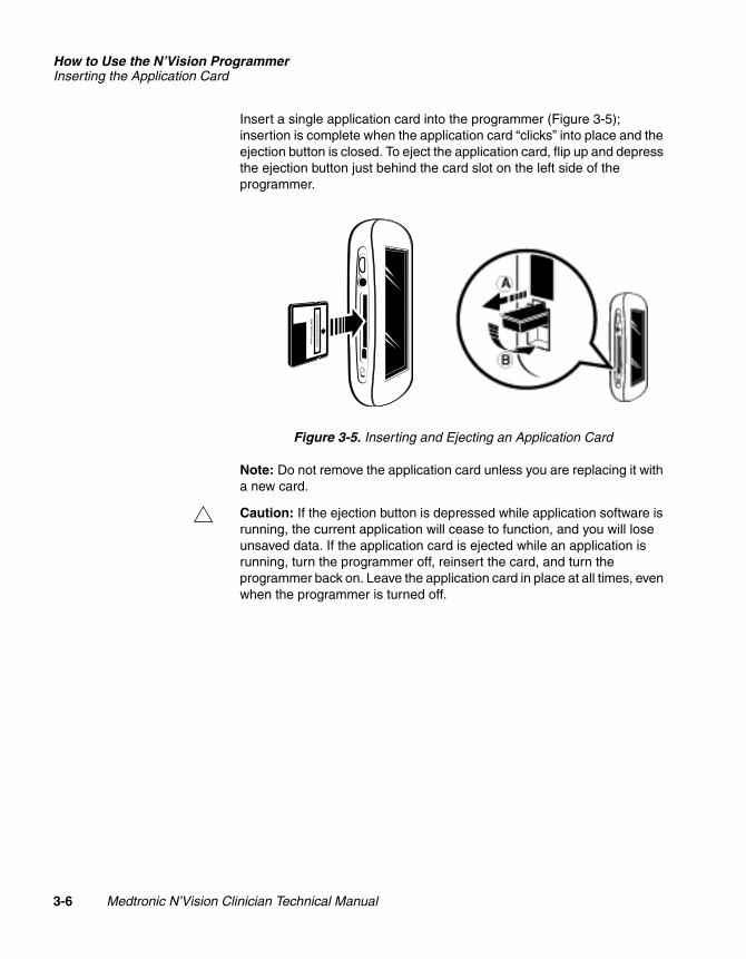
Insert a single application card into the programmer (Figure 3-5); insertion is complete when the application card “clicks” into place and the ejection button is closed. To eject the application card, flip up and depress the ejection button just behind the card slot on the left side of the programmer.
Figure 3-5. Inserting and Ejecting an Application Card
Note: Do not remove the application card unless you are replacing it with a new card.
# Caution: If the ejection button is depressed while application software is running, the current application will cease to function, and you will lose unsaved data. If the application card is ejected while an application is running, turn the programmer off, reinsert the card, and turn the programmer back on. Leave the application card in place at all times, even when the programmer is turned off.
3-6 Medtronic N’Vision Clinician Technical Manual
221438002Rev X
Size inches (mm)/CTCUC20010xxxx EN xxx releaseDefine as desired
How to Use the N’Vision ProgrammerInserting the Application Card
2R
MEDTRONIC CONFIDENTIAL REF_R18
Stand-by Mode
When the N’Vision Programmer is powered up and in use, the programmer enters Stand-by Mode if no input is received during a continuous 6-minute period of time. During Stand-by Mode, the programmer screen goes blank. The programmer leaves Stand-by Mode and becomes active when the user activates the power button on the programmer (refer to page 3-2).
If an application is running when the programmer goes into Stand-by Mode, and the user activates the power key on the programmer within 1 hour of Stand-by Mode initiation, the programmer returns to the function that was in use at the time of Stand-by Mode onset. If, however, the power switch is not activated within 1 hour of Stand-by Mode initiation, the programmer will shut down. When the power button is activated after the 1-hour period, it reverts to the start-up sequence and self test.
# Caution: If the programmer is in Stand-by Mode for more than 1 hour, all data from the application in use at the time of Stand-by Mode onset will be lost.
Medtronic N’Vision Clinician Technical Manual 3-7
21438002ev X
Size inches (mm)/CTCUC20010xxxx EN xxx releaseDefine as desired
How to Use the N’Vision ProgrammerNavigating Menu Options
MEDTRONIC CONFIDENTIAL REF_R18
Navigating Menu Options
The Programmer Display
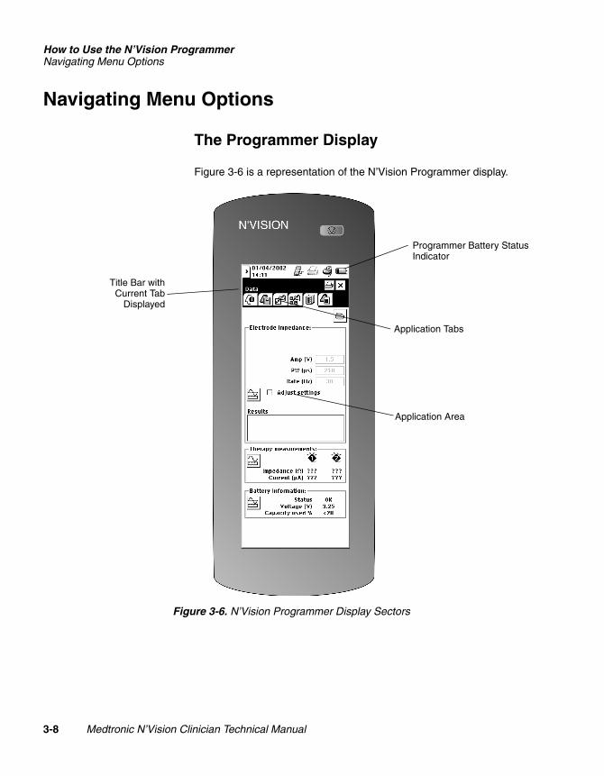
Figure 3-6 is a representation of the N’Vision Programmer display.
Figure 3-6. N’Vision Programmer Display Sectors
Programmer Battery Status Indicator
Application Tabs
Application Area
Title Bar withCurrent Tab
Displayed
3-8 Medtronic N’Vision Clinician Technical Manual
221438002Rev X
Size inches (mm)/CTCUC20010xxxx EN xxx releaseDefine as desired
How to Use the N’Vision ProgrammerNavigating Menu Options
2R
MEDTRONIC CONFIDENTIAL REF_R18
Using the Display
Most user input to the N’Vision Programmer is via the display, which is the preferred mode of access to configure programmer settings and to operate applications housed on the application card. The display responds to stylus or fingertip touch.
A stylus is supplied with the device and can be stored in a groove molded into the right side of the programmer. To remove the stylus from its storage area, slide it down and out of the groove. Use the pointed end of the stylus to make contact with the display screen.
Display Calibration
The display on the N’Vision Programmer may require periodic calibration. For details, refer to “Chapter 4, Programmer Maintenance.”
# Caution: Use of the N’Vision Programmer while the screen is out of calibration may result in unintended programming or function selection.
Using the Scroll Wheel and Program Key
A scroll wheel located on the left side of the N’Vision Programmer (Figure 3-7) allows the user to select graduated parameters. The wheel turns in both directions in discrete increments and is positioned on the device to facilitate single-handed use of the programmer. The scroll wheel also can be depressed partially into the programmer, and depression of the wheel communicates an “enter” or “select” function to the device. The scroll wheel functions are application specific and may vary from one therapy to another.
Medtronic N’Vision Clinician Technical Manual 3-9
21438002ev X
Size inches (mm)/CTCUC20010xxxx EN xxx releaseDefine as desired
How to Use the N’Vision ProgrammerNavigating Menu Options
MEDTRONIC CONFIDENTIAL REF_R18
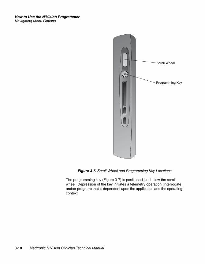
Figure 3-7. Scroll Wheel and Programming Key Locations
The programming key (Figure 3-7) is positioned just below the scroll wheel. Depression of the key initiates a telemetry operation (interrogate and/or program) that is dependent upon the application and the operating context.
P
Scroll Wheel
Programming Key
3-10 Medtronic N’Vision Clinician Technical Manual
221438002Rev X
Size inches (mm)/CTCUC20010xxxx EN xxx releaseDefine as desired
How to Use the N’Vision ProgrammerProgrammer Operation
2R
MEDTRONIC CONFIDENTIAL REF_R18
Programmer Operation
Start-up and Self-test Sequence
When the power key is activated on the N’Vision Programmer, a series of self-tests are initiated. These self-tests are designed to ensure the programmer is functioning properly. During the time the programmer is in the self-test mode (approximately 5 seconds), the following parameters are checked:
■ Power supply
■ Battery power levels
■ Memory
■ Other hardware
If one or more of the self-tests fail, the programmer alerts the user graphically and with a failure sound (five flat tones in rapid succession). The programmer then displays instructions on how to proceed.
Following successful completion of the self-test, the programmer displays a menu that allows selection of the desired program, along with a Programmer Status Bar that allows the user to select and monitor various programmer functions.
Programmer Status Bar
The status of several functions can be monitored by review of icons on the Programmer Status Bar (refer to Chapter 2, “Programmer Description”).
The icons on the Programmer Status Bar are “inactive” (designed to give only information on the performance of the various parameters graphically represented by the icons).
Status Bar icons are presented on page 3-12 and page 3-13.
Medtronic N’Vision Clinician Technical Manual 3-11
21438002ev X
Size inches (mm)/CTCUC20010xxxx EN xxx releaseDefine as desired
How to Use the N’Vision ProgrammerProgrammer Operation
MEDTRONIC CONFIDENTIAL REF_R18
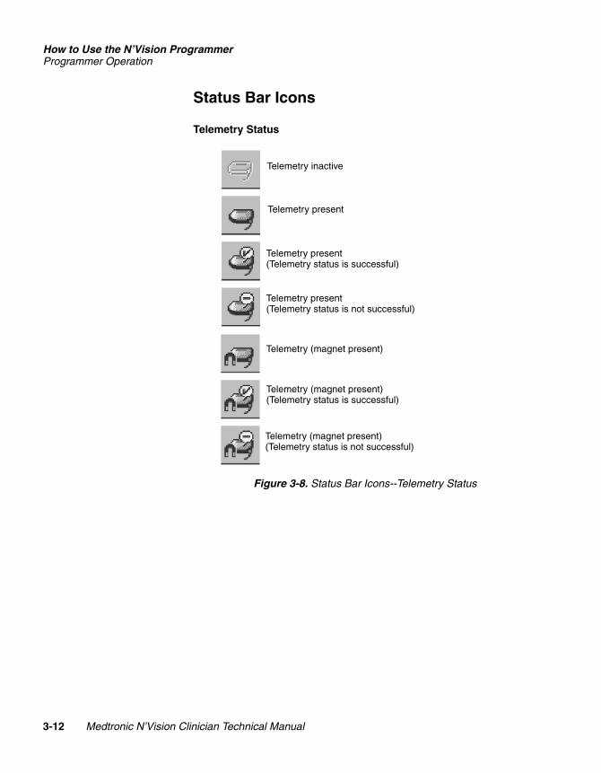
Status Bar Icons
Telemetry Status
Figure 3-8. Status Bar Icons--Telemetry Status
Telemetry inactive
Telemetry present
Telemetry present(Telemetry status is successful)
Telemetry present(Telemetry status is not successful)
Telemetry (magnet present)
Telemetry (magnet present)(Telemetry status is successful)
Telemetry (magnet present)(Telemetry status is not successful)
3-12 Medtronic N’Vision Clinician Technical Manual
221438002Rev X
Size inches (mm)/CTCUC20010xxxx EN xxx releaseDefine as desired
How to Use the N’Vision ProgrammerProgrammer Operation
2R
MEDTRONIC CONFIDENTIAL REF_R18
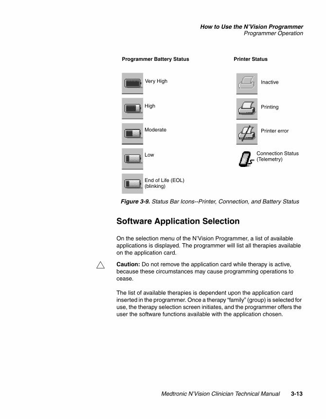
Figure 3-9. Status Bar Icons--Printer, Connection, and Battery Status
Software Application Selection
On the selection menu of the N’Vision Programmer, a list of available applications is displayed. The programmer will list all therapies available on the application card.
# Caution: Do not remove the application card while therapy is active, because these circumstances may cause programming operations to cease.
The list of available therapies is dependent upon the application card inserted in the programmer. Once a therapy “family” (group) is selected for use, the therapy selection screen initiates, and the programmer offers the user the software functions available with the application chosen.
Printer StatusProgrammer Battery Status
Very High
High
Moderate
Low
End of Life (EOL) (blinking)
Inactive
Printing
Printer error
Connection Status (Telemetry)
Medtronic N’Vision Clinician Technical Manual 3-13
21438002ev X
Size inches (mm)/CTCUC20010xxxx EN xxx releaseDefine as desired
How to Use the N’Vision ProgrammerProgrammer Operation
MEDTRONIC CONFIDENTIAL REF_R18
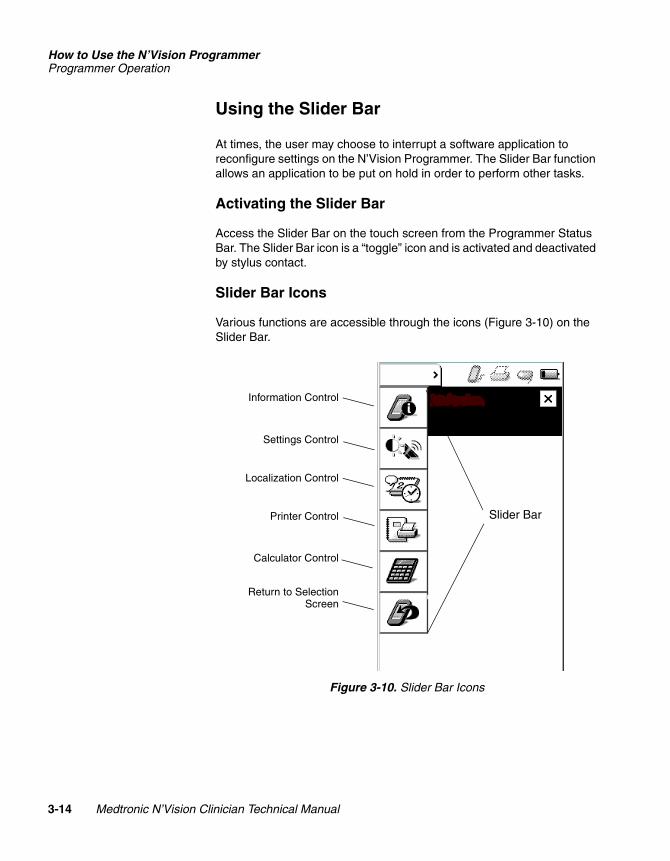
Using the Slider Bar
At times, the user may choose to interrupt a software application to reconfigure settings on the N’Vision Programmer. The Slider Bar function allows an application to be put on hold in order to perform other tasks.
Activating the Slider Bar
Access the Slider Bar on the touch screen from the Programmer Status Bar. The Slider Bar icon is a “toggle” icon and is activated and deactivated by stylus contact.
Slider Bar Icons
Various functions are accessible through the icons (Figure 3-10) on the Slider Bar.
Figure 3-10. Slider Bar Icons
Slider Bar
Information Control
Localization Control
Printer Control
Calculator Control
Return to SelectionScreen
Settings Control
3-14 Medtronic N’Vision Clinician Technical Manual
221438002Rev X
Size inches (mm)/CTCUC20010xxxx EN xxx releaseDefine as desired
How to Use the N’Vision ProgrammerProgrammer Operation
2R
MEDTRONIC CONFIDENTIAL REF_R18
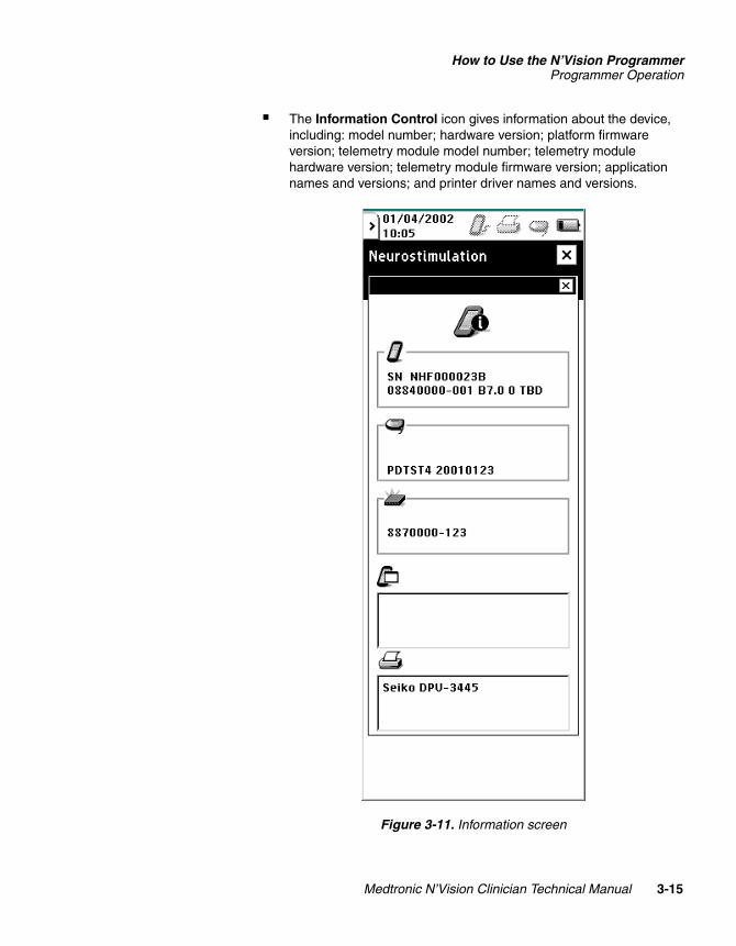
■ The Information Control icon gives information about the device, including: model number; hardware version; platform firmware version; telemetry module model number; telemetry module hardware version; telemetry module firmware version; application names and versions; and printer driver names and versions.
Figure 3-11. Information screen
Medtronic N’Vision Clinician Technical Manual 3-15
21438002ev X
Size inches (mm)/CTCUC20010xxxx EN xxx releaseDefine as desired
How to Use the N’Vision ProgrammerProgrammer Operation
MEDTRONIC CONFIDENTIAL REF_R18
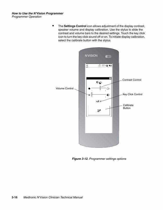
■ The Settings Control icon allows adjustment of the display contrast, speaker volume and display calibration. Use the stylus to slide the contrast and volume bars to the desired settings. Touch the key click icon to turn the key click sound off or on. To initiate display calibration, select the calibrate button with the stylus.
Figure 3-12. Programmer settings options
N'VISION
CalibrateButton
Key Click Control
Contrast Control
Volume Control
3-16 Medtronic N’Vision Clinician Technical Manual
221438002Rev X
Size inches (mm)/CTCUC20010xxxx EN xxx releaseDefine as desired
How to Use the N’Vision ProgrammerProgrammer Operation
2R
MEDTRONIC CONFIDENTIAL REF_R18
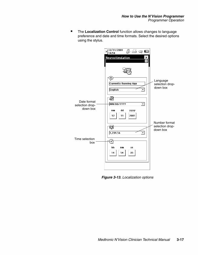
■ The Localization Control function allows changes to language preference and date and time formats. Select the desired options using the stylus.
Figure 3-13. Localization options
Language selection drop-down box
Number format selection drop-down box
Date formatselection drop-
down box
Time selectionbox
Medtronic N’Vision Clinician Technical Manual 3-17
21438002ev X
Size inches (mm)/CTCUC20010xxxx EN xxx releaseDefine as desired
How to Use the N’Vision ProgrammerProgrammer Operation
MEDTRONIC CONFIDENTIAL REF_R18
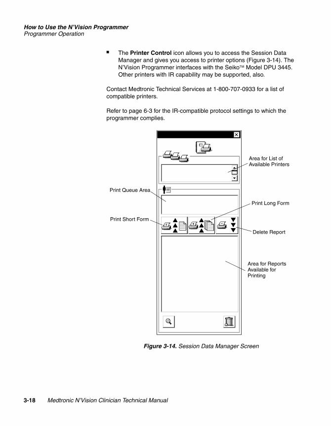
■ The Printer Control icon allows you to access the Session Data Manager and gives you access to printer options (Figure 3-14). The N’Vision Programmer interfaces with the Seiko Model DPU 3445. Other printers with IR capability may be supported, also.
Contact Medtronic Technical Services at 1-800-707-0933 for a list of compatible printers.
Refer to page 6-3 for the IR-compatible protocol settings to which the programmer complies.
Figure 3-14. Session Data Manager Screen
Delete Report
Print Long Form
Print Short Form
Area for List of Available Printers
Area for Reports Available for Printing
Print Queue Area
3-18 Medtronic N’Vision Clinician Technical Manual
221438002Rev X
Size inches (mm)/CTCUC20010xxxx EN xxx releaseDefine as desired
How to Use the N’Vision ProgrammerProgrammer Operation
2R
MEDTRONIC CONFIDENTIAL REF_R18
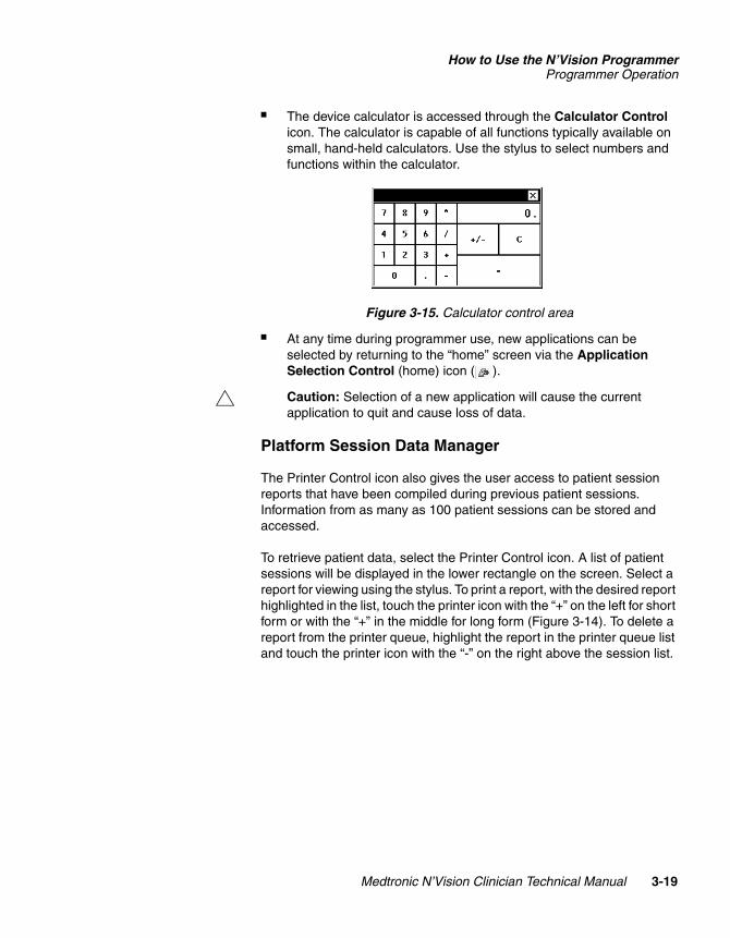
■ The device calculator is accessed through the Calculator Control icon. The calculator is capable of all functions typically available on small, hand-held calculators. Use the stylus to select numbers and functions within the calculator.
Figure 3-15. Calculator control area
■ At any time during programmer use, new applications can be selected by returning to the “home” screen via the Application Selection Control (home) icon ( ).
# Caution: Selection of a new application will cause the current application to quit and cause loss of data.
Platform Session Data Manager
The Printer Control icon also gives the user access to patient session reports that have been compiled during previous patient sessions. Information from as many as 100 patient sessions can be stored and accessed.
To retrieve patient data, select the Printer Control icon. A list of patient sessions will be displayed in the lower rectangle on the screen. Select a report for viewing using the stylus. To print a report, with the desired report highlighted in the list, touch the printer icon with the “+” on the left for short form or with the “+” in the middle for long form (Figure 3-14). To delete a report from the printer queue, highlight the report in the printer queue list and touch the printer icon with the “-” on the right above the session list.
Medtronic N’Vision Clinician Technical Manual 3-19
21438002ev X
Size inches (mm)/CTCUC20010xxxx EN xxx releaseDefine as desired
How to Use the N’Vision ProgrammerProgrammer Operation
MEDTRONIC CONFIDENTIAL REF_R18
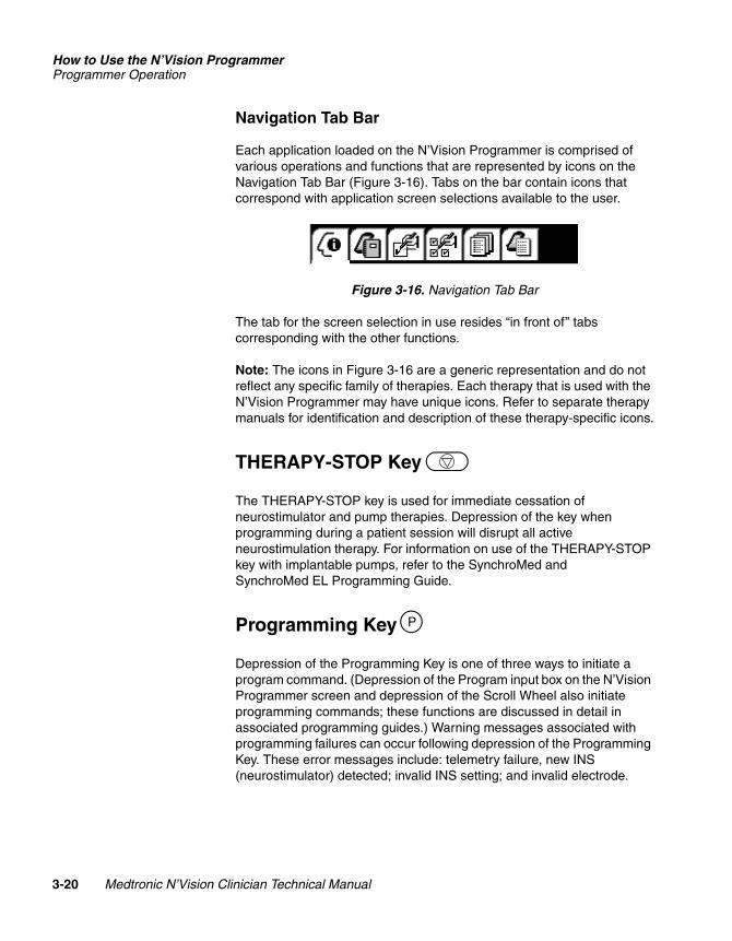
Navigation Tab Bar
Each application loaded on the N’Vision Programmer is comprised of various operations and functions that are represented by icons on the Navigation Tab Bar (Figure 3-16). Tabs on the bar contain icons that correspond with application screen selections available to the user.
Figure 3-16. Navigation Tab Bar
The tab for the screen selection in use resides “in front of” tabs corresponding with the other functions.
Note: The icons in Figure 3-16 are a generic representation and do not reflect any specific family of therapies. Each therapy that is used with the N’Vision Programmer may have unique icons. Refer to separate therapy manuals for identification and description of these therapy-specific icons.
THERAPY-STOP Key
The THERAPY-STOP key is used for immediate cessation of neurostimulator and pump therapies. Depression of the key when programming during a patient session will disrupt all active neurostimulation therapy. For information on use of the THERAPY-STOP key with implantable pumps, refer to the SynchroMed and SynchroMed EL Programming Guide.
Programming Key
Depression of the Programming Key is one of three ways to initiate a program command. (Depression of the Program input box on the N’Vision Programmer screen and depression of the Scroll Wheel also initiate programming commands; these functions are discussed in detail in associated programming guides.) Warning messages associated with programming failures can occur following depression of the Programming Key. These error messages include: telemetry failure, new INS (neurostimulator) detected; invalid INS setting; and invalid electrode.
P
3-20 Medtronic N’Vision Clinician Technical Manual
221438002Rev X
Size inches (mm)/CTCUC20010xxxx EN xxx releaseDefine as desired
How to Use the N’Vision ProgrammerProgrammer Connections
2R
MEDTRONIC CONFIDENTIAL REF_R18
Programmer Connections
Communicating with a Printer
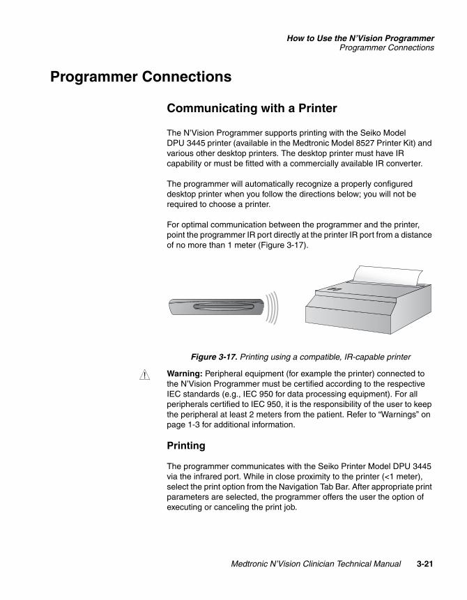
The N’Vision Programmer supports printing with the Seiko Model DPU 3445 printer (available in the Medtronic Model 8527 Printer Kit) and various other desktop printers. The desktop printer must have IR capability or must be fitted with a commercially available IR converter.
The programmer will automatically recognize a properly configured desktop printer when you follow the directions below; you will not be required to choose a printer.
For optimal communication between the programmer and the printer, point the programmer IR port directly at the printer IR port from a distance of no more than 1 meter (Figure 3-17).
Figure 3-17. Printing using a compatible, IR-capable printer
w Warning: Peripheral equipment (for example the printer) connected to the N’Vision Programmer must be certified according to the respective IEC standards (e.g., IEC 950 for data processing equipment). For all peripherals certified to IEC 950, it is the responsibility of the user to keep the peripheral at least 2 meters from the patient. Refer to “Warnings” on page 1-3 for additional information.
Printing
The programmer communicates with the Seiko Printer Model DPU 3445 via the infrared port. While in close proximity to the printer (<1 meter), select the print option from the Navigation Tab Bar. After appropriate print parameters are selected, the programmer offers the user the option of executing or canceling the print job.
Medtronic N’Vision Clinician Technical Manual 3-21
21438002ev X
Size inches (mm)/CTCUC20010xxxx EN xxx releaseDefine as desired
How to Use the N’Vision ProgrammerTelemetry Module Use
MEDTRONIC CONFIDENTIAL REF_R18
Telemetry Module Use
The telemetry module located on the back of the N’Vision Programmer may be used while locked in place on the programmer or while extended.
Refer to the appropriate therapy manual for specific device programming and interrogation instructions.
w Warning: When using the programmer in a sterile field, place the programmer and programming head in a sterile bag. The programmer is not sterile and cannot be sterilized.
Using the Telemetry Module Attached to the Programmer
If using the telemetry head while it is locked onto the programmer, position the programmer so that the telemetry head is on the side closest to the implanted device. Prior to the start of interrogation or programming, ensure that the telemetry head is positioned directly over and as close as practical to the implanted device.
Using the Telemetry Module Detached from the Programmer
To unlock the telemetry module from the programmer, press down and forward on the module. After the telemetry head is pushed slightly forward and out of the locked position, grasp the top of the module with one hand, and pull it out to the desired length.
Ensure that the telemetry head is directly over and as close as practical to the implanted device. If the telemetry head is used while extended on the cable, the user will see a green light on the back of the telemetry head, indicating successful interrogation or programming. An amber light indicates a failure or error.
3-22 Medtronic N’Vision Clinician Technical Manual
221438002Rev X
Size inches (mm)/CTCUC20010xxxx EN xxx releaseDefine as desired
How to Use the N’Vision ProgrammerTelemetry Module Use
2R
MEDTRONIC CONFIDENTIAL REF_R18
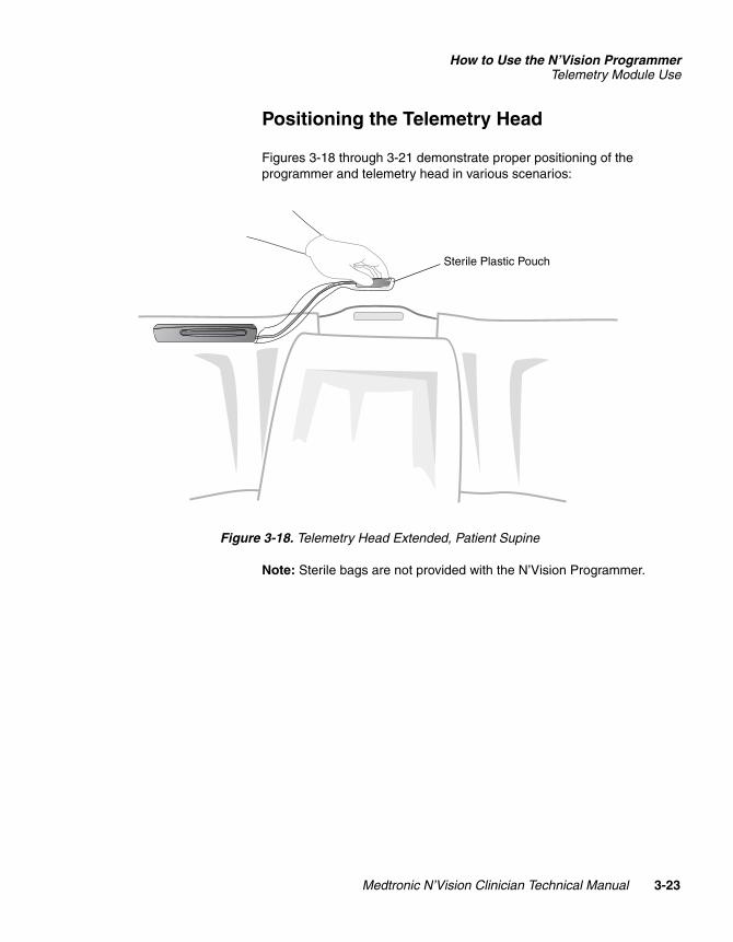
Positioning the Telemetry Head
Figures 3-18 through 3-21 demonstrate proper positioning of the programmer and telemetry head in various scenarios:
Figure 3-18. Telemetry Head Extended, Patient Supine
Note: Sterile bags are not provided with the N’Vision Programmer.
Sterile Plastic Pouch
Medtronic N’Vision Clinician Technical Manual 3-23
21438002ev X
Size inches (mm)/CTCUC20010xxxx EN xxx releaseDefine as desired
How to Use the N’Vision ProgrammerTelemetry Module Use
MEDTRONIC CONFIDENTIAL REF_R18
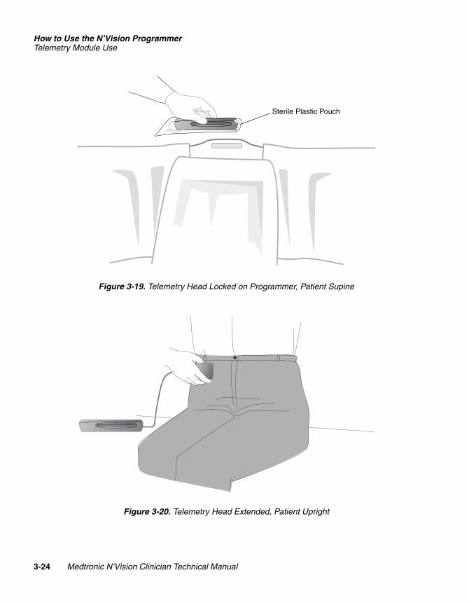
Figure 3-19. Telemetry Head Locked on Programmer, Patient Supine
Figure 3-20. Telemetry Head Extended, Patient Upright
Sterile Plastic Pouch
3-24 Medtronic N’Vision Clinician Technical Manual
221438002Rev X
Size inches (mm)/CTCUC20010xxxx EN xxx releaseDefine as desired
How to Use the N’Vision ProgrammerTelemetry Module Use
2R
MEDTRONIC CONFIDENTIAL REF_R18
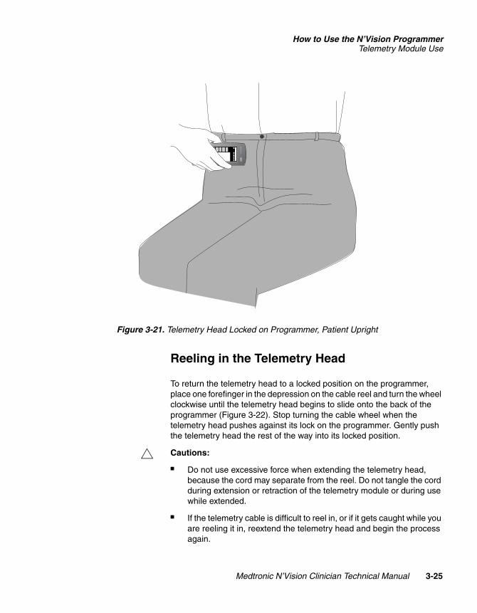
Figure 3-21. Telemetry Head Locked on Programmer, Patient Upright
Reeling in the Telemetry Head
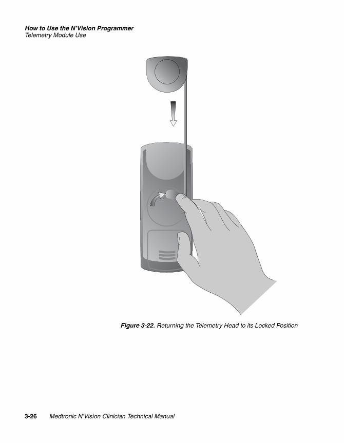
To return the telemetry head to a locked position on the programmer, place one forefinger in the depression on the cable reel and turn the wheel clockwise until the telemetry head begins to slide onto the back of the programmer (Figure 3-22). Stop turning the cable wheel when the telemetry head pushes against its lock on the programmer. Gently push the telemetry head the rest of the way into its locked position.
# Cautions:
■ Do not use excessive force when extending the telemetry head, because the cord may separate from the reel. Do not tangle the cord during extension or retraction of the telemetry module or during use while extended.
■ If the telemetry cable is difficult to reel in, or if it gets caught while you are reeling it in, reextend the telemetry head and begin the process again.
8840 Program
mer
Medtronic N’Vision Clinician Technical Manual 3-25
21438002ev X
Size inches (mm)/CTCUC20010xxxx EN xxx releaseDefine as desired
How to Use the N’Vision ProgrammerTelemetry Module Use
MEDTRONIC CONFIDENTIAL REF_R18
Figure 3-22. Returning the Telemetry Head to its Locked Position
3-26 Medtronic N’Vision Clinician Technical Manual
221438002Rev X
Size inches (mm)/CTCUC20010xxxx EN xxx releaseDefine as desired
How to Use the N’Vision ProgrammerTelemetry Module Use
2R
MEDTRONIC CONFIDENTIAL REF_R18
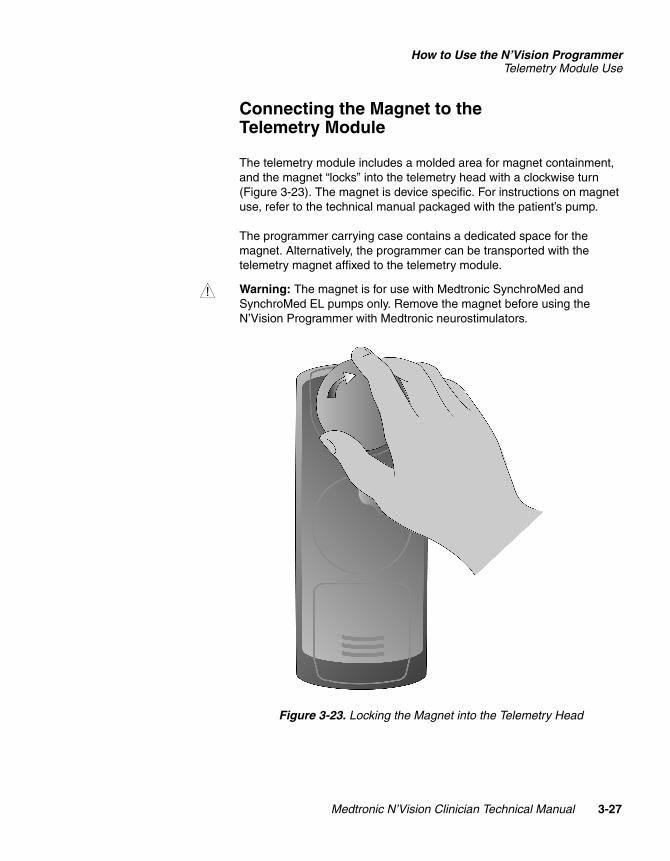
Connecting the Magnet to the Telemetry Module
The telemetry module includes a molded area for magnet containment, and the magnet “locks” into the telemetry head with a clockwise turn (Figure 3-23). The magnet is device specific. For instructions on magnet use, refer to the technical manual packaged with the patient’s pump.
The programmer carrying case contains a dedicated space for the magnet. Alternatively, the programmer can be transported with the telemetry magnet affixed to the telemetry module.
w Warning: The magnet is for use with Medtronic SynchroMed and SynchroMed EL pumps only. Remove the magnet before using the N’Vision Programmer with Medtronic neurostimulators.
Figure 3-23. Locking the Magnet into the Telemetry Head
Medtronic N’Vision Clinician Technical Manual 3-27
21438002ev X
Size inches (mm)/CTCUC20010xxxx EN xxx releaseDefine as desired
How to Use the N’Vision ProgrammerTelemetry Module Use
MEDTRONIC CONFIDENTIAL REF_R18
# Cautions:
■ The magnet used in pump programming creates a magnetic field that may affect other implanted programmable medical devices or magnetic storage devices. The physician must identify the other devices and assess the effects of a magnetic field on that device.
■ Do not allow the magnet to come in contact with magnetic substances. Do not place the magnet on or near computer monitors or magnetic storage devices, disks, or tapes.
3-28 Medtronic N’Vision Clinician Technical Manual
221438002Rev X
Size inches (mm)/CTCUC20010xxxx EN xxx releaseDefine as desired
Medtronic N’Vision C
221438002Rev X
MEDTRONIC CONFIDENTIAL REF_R18
4
Programmer Maintenance 4Changing the Programmer Batteries 4-2
Cleaning the Display 4-3
Display Calibration 4-4
linician Technical Manual 4-1
Size inches (mm)/CTCUC20010xxxx EN xxx releaseDefine as desired
Programmer MaintenanceChanging the Programmer Batteries
MEDTRONIC CONFIDENTIAL REF_R18
Changing the Programmer Batteries
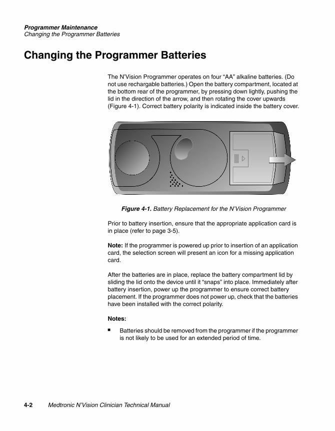
The N’Vision Programmer operates on four “AA” alkaline batteries. (Do not use rechargable batteries.) Open the battery compartment, located at the bottom rear of the programmer, by pressing down lightly, pushing the lid in the direction of the arrow, and then rotating the cover upwards (Figure 4-1). Correct battery polarity is indicated inside the battery cover.
Figure 4-1. Battery Replacement for the N’Vision Programmer
Prior to battery insertion, ensure that the appropriate application card is in place (refer to page 3-5).
Note: If the programmer is powered up prior to insertion of an application card, the selection screen will present an icon for a missing application card.
After the batteries are in place, replace the battery compartment lid by sliding the lid onto the device until it “snaps” into place. Immediately after battery insertion, power up the programmer to ensure correct battery placement. If the programmer does not power up, check that the batteries have been installed with the correct polarity.
Notes:
■ Batteries should be removed from the programmer if the programmer is not likely to be used for an extended period of time.
4-2 Medtronic N’Vision Clinician Technical Manual
221438002Rev X
Size inches (mm)/CTCUC20010xxxx EN xxx releaseDefine as desired
Programmer MaintenanceCleaning the Display
2R
MEDTRONIC CONFIDENTIAL REF_R18
■ “AA” battery usage and depletion increases with the use of a magnet, which is required when programming some implantable devices. Use high capacity AA batteries (2850-3000 milliamp hours) to power the N’Vision Clinician Programmer. When the batteries that power the programmer are becoming depleted, a pop-up warning message will appear on the programmer screen. When this message appears, power down the programmer, remove the spent batteries, and insert fresh batteries.
# Caution: Battery depletion may lead to loss of data and/or inability to program. Ensure that fresh “AA” batteries are available as replacements at all times.
Battery Replacement
Batteries should be replaced after every 40 hours or when the battery status shows low battery. Batteries must be replaced when the battery status indicates EOL (blinking). Do not use abrasive cleaners on the battery contacts.
# Caution: Dispose of depleted batteries in accordance with local regulations.
Back-up Battery
A lithium battery supplied with the programmer runs the programmer internal clock when no main “AA” batteries are installed. The life expectancy of the lithium battery is 3 years, and it can be replaced by the user. The lithium battery compartment is located beneath the “AA” battery compartment. To access the lithium battery compartment, remove the “AA” batteries from the device. The lithium battery in the N’Vision Programmer is a BR1225 standard lithium coin cell. Insert a new lithium battery of the same type (BR1225). Replace the “AA” batteries.
Cleaning the Display
Do not use abrasive or nonabrasive cleansers on the display. The display should be cleaned only with a soft, dry, lint-free cloth.
# Caution: Scratches on the display may adversely affect programmer operation by interfering with display option selection. If scratches are present, the programmer may need to be repaired or replaced.
Medtronic N’Vision Clinician Technical Manual 4-3
21438002ev X
Size inches (mm)/CTCUC20010xxxx EN xxx releaseDefine as desired
Programmer MaintenanceDisplay Calibration
MEDTRONIC CONFIDENTIAL REF_R18
Display Calibration
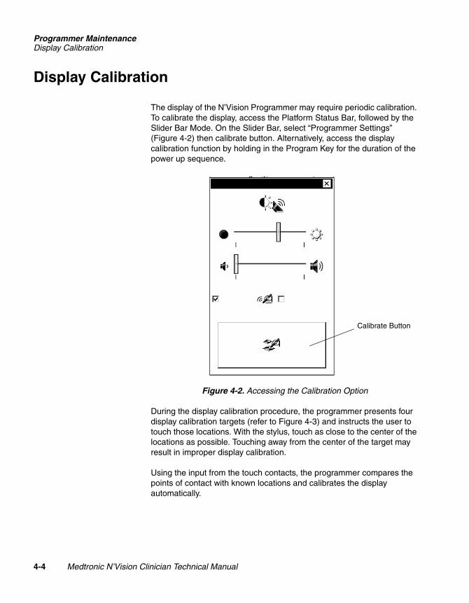
The display of the N’Vision Programmer may require periodic calibration. To calibrate the display, access the Platform Status Bar, followed by the Slider Bar Mode. On the Slider Bar, select “Programmer Settings” (Figure 4-2) then calibrate button. Alternatively, access the display calibration function by holding in the Program Key for the duration of the power up sequence.
Figure 4-2. Accessing the Calibration Option
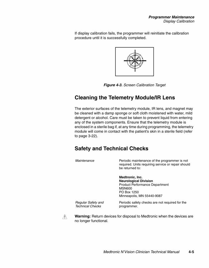
During the display calibration procedure, the programmer presents four display calibration targets (refer to Figure 4-3) and instructs the user to touch those locations. With the stylus, touch as close to the center of the locations as possible. Touching away from the center of the target may result in improper display calibration.
Using the input from the touch contacts, the programmer compares the points of contact with known locations and calibrates the display automatically.
Calibrate Button
4-4 Medtronic N’Vision Clinician Technical Manual
221438002Rev X
Size inches (mm)/CTCUC20010xxxx EN xxx releaseDefine as desired
Programmer MaintenanceDisplay Calibration
2R
MEDTRONIC CONFIDENTIAL REF_R18
If display calibration fails, the programmer will reinitiate the calibration procedure until it is successfully completed.
Figure 4-3. Screen Calibration Target
Cleaning the Telemetry Module/IR Lens
The exterior surfaces of the telemetry module, IR lens, and magnet may be cleaned with a damp sponge or soft cloth moistened with water, mild detergent or alcohol. Care must be taken to prevent liquid from entering any of the system components. Ensure that the telemetry module is enclosed in a sterile bag if, at any time during programming, the telemetry module will come in contact with the patient’s skin in a sterile field (refer to page 3-22).
Safety and Technical Checks
w Warning: Return devices for disposal to Medtronic when the devices are no longer functional.
Maintenance Periodic maintenance of the programmer is not required. Units requiring service or repair should be returned to:
Medtronic, Inc.Neurological DivisionProduct Performance DepartmentMSN600PO Box 1250Minneapolis, MN 55440-9087
Regular Safety and Technical Checks
Periodic safety checks are not required for the programmer.
Medtronic N’Vision Clinician Technical Manual 4-5
21438002ev X
Size inches (mm)/CTCUC20010xxxx EN xxx releaseDefine as desired
Programmer MaintenanceDisplay Calibration
MEDTRONIC CONFIDENTIAL REF_R18
4-6 Medtronic N’Vision Clinician Technical Manual
221438002Rev X
Size inches (mm)/CTCUC20010xxxx EN xxx releaseDefine as desired
Medtronic N’Vision C
221438002Rev X
MEDTRONIC CONFIDENTIAL REF_R18
5
Troubleshooting 5Troubleshooting Reference Guide 5-2
linician Technical Manual 5-1
Size inches (mm)/CTCUC20010xxxx EN xxx releaseDefine as desired
TroubleshootingTroubleshooting Reference Guide
MEDTRONIC CONFIDENTIAL REF_R18
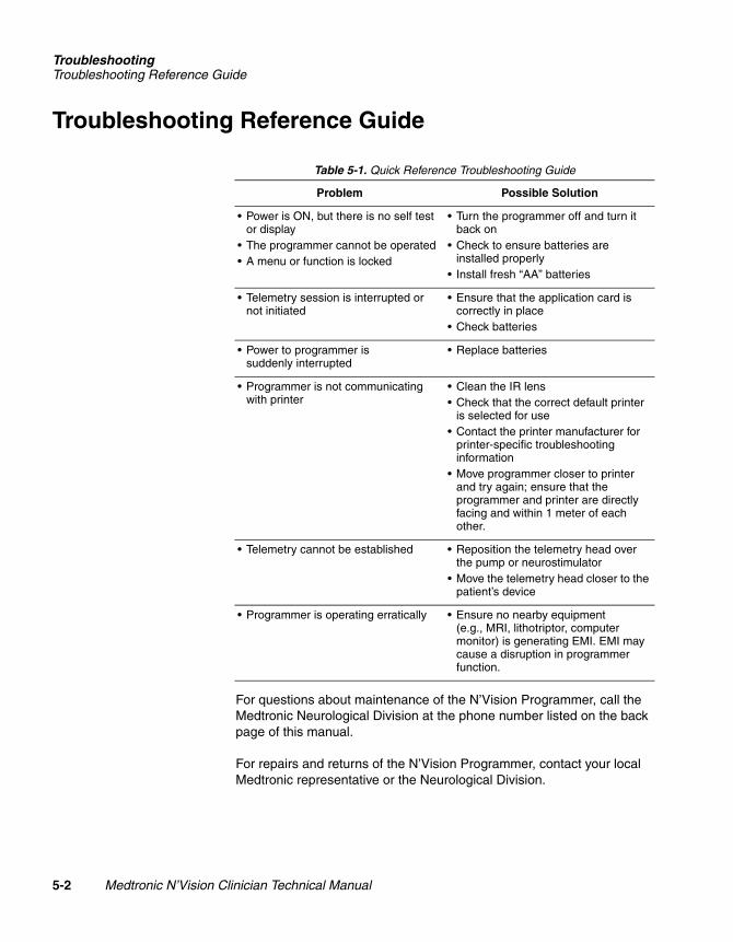
Troubleshooting Reference Guide
For questions about maintenance of the N’Vision Programmer, call the Medtronic Neurological Division at the phone number listed on the back page of this manual.
For repairs and returns of the N’Vision Programmer, contact your local Medtronic representative or the Neurological Division.
Table 5-1. Quick Reference Troubleshooting Guide
Problem Possible Solution
• Power is ON, but there is no self test or display
• The programmer cannot be operated• A menu or function is locked
• Turn the programmer off and turn it back on
• Check to ensure batteries are installed properly
• Install fresh “AA” batteries
• Telemetry session is interrupted or not initiated
• Ensure that the application card is correctly in place
• Check batteries
• Power to programmer is suddenly interrupted
• Replace batteries
• Programmer is not communicating with printer
• Clean the IR lens• Check that the correct default printer
is selected for use• Contact the printer manufacturer for
printer-specific troubleshooting information
• Move programmer closer to printer and try again; ensure that the programmer and printer are directly facing and within 1 meter of each other.
• Telemetry cannot be established • Reposition the telemetry head over the pump or neurostimulator
• Move the telemetry head closer to the patient’s device
• Programmer is operating erratically • Ensure no nearby equipment (e.g., MRI, lithotriptor, computer monitor) is generating EMI. EMI may cause a disruption in programmer function.
5-2 Medtronic N’Vision Clinician Technical Manual
221438002Rev X
Size inches (mm)/CTCUC20010xxxx EN xxx releaseDefine as desired
Medtronic N’Vision C
221438002Rev X
MEDTRONIC CONFIDENTIAL REF_R18
6
Specifications and Warranty 6N’Vision Programmer Specifications 6-2
Warranty 6-4
linician Technical Manual 6-1
Size inches (mm)/CTCUC20010xxxx EN xxx releaseDefine as desired
Specifications and WarrantyN’Vision Programmer Specifications
MEDTRONIC CONFIDENTIAL REF_R18
N’Vision Programmer Specifications
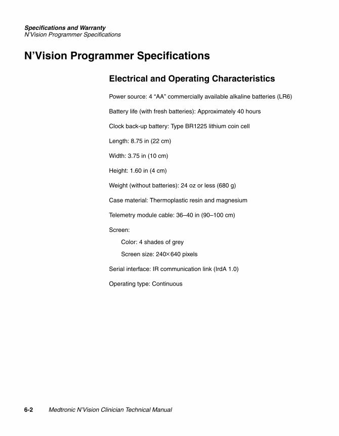
Electrical and Operating Characteristics
Power source: 4 “AA” commercially available alkaline batteries (LR6)
Battery life (with fresh batteries): Approximately 40 hours
Clock back-up battery: Type BR1225 lithium coin cell
Length: 8.75 in (22 cm)
Width: 3.75 in (10 cm)
Height: 1.60 in (4 cm)
Weight (without batteries): 24 oz or less (680 g)
Case material: Thermoplastic resin and magnesium
Telemetry module cable: 36–40 in (90–100 cm)
Screen:
Color: 4 shades of grey
Screen size: 240×640 pixels
Serial interface: IR communication link (IrdA 1.0)
Operating type: Continuous
6-2 Medtronic N’Vision Clinician Technical Manual
221438002Rev X
Size inches (mm)/CTCUC20010xxxx EN xxx releaseDefine as desired
Specifications and WarrantyN’Vision Programmer Specifications
2R
MEDTRONIC CONFIDENTIAL REF_R18
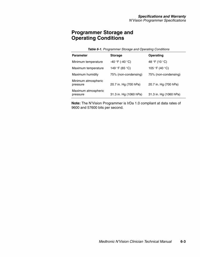
Programmer Storage and Operating Conditions
Note: The N’Vision Programmer is IrDa 1.0 compliant at data rates of 9600 and 57600 bits per second.
Table 6-1. Programmer Storage and Operating Conditions
Parameter Storage Operating
Minimum temperature -40 °F (-40 °C) 48 °F (10 °C)
Maximum temperature 149 °F (65 °C) 105 °F (40 °C)
Maximum humidity 75% (non-condensing) 75% (non-condensing)
Minimum atmospheric pressure 20.7 in. Hg (700 hPa) 20.7 in. Hg (700 hPa)
Maximum atmospheric pressure 31.3 in. Hg (1060 hPa) 31.3 in. Hg (1060 hPa)
Medtronic N’Vision Clinician Technical Manual 6-3
21438002ev X
Size inches (mm)/CTCUC20010xxxx EN xxx releaseDefine as desired
Specifications and WarrantyWarranty
MEDTRONIC CONFIDENTIAL REF_R18
Warranty
Medtronic® Neurological Equipment Limited Warranty1 (U.S. Customers Only)
A. This Limited Warranty provides the following assurance to the purchaser of the Medtronic® N’Vision™ Model 8840 Programmer, hereafter referred to as “Equipment”:
(1) Should the Equipment fail to function within normal tolerances due to a defect in materials or workmanship within a period of one (1) year, commencing with the delivery of the Equipment to the purchaser, Medtronic will at its option: (a) repair or replace any part or parts of the Equipment; (b) issue a credit to the purchaser equal to the Purchase Price, as defined in Subsection A(2), against the purchase of the replacement Equipment or (c) provide a functionally comparable replacement Equipment at no charge.
(2) As used herein, Purchase Price shall mean the lesser of the net invoiced price of the original, or current functionally comparable, or replacement Equipment.
B. To qualify for Limited Warranty set forth in Section A(1), the following conditions must be met:
(1) The Equipment must be returned to Medtronic within thirty (30) days after discovery of the defect, (Medtronic may, at its option, repair the Equipment on site).
(2) The Equipment must not have been repaired or altered outside of Medtronic's factory in any way which, in the judgment of Medtronic, affects its stability and reliability. The Equipment must not have been subjected to misuse, abuse or accident.
C. This Limited Warranty is limited to its express terms. In particular:
(1) Except as expressly provided by this Limited Warranty, MEDTRONIC IS NOT RESPONSIBLE FOR ANY DIRECT, INCIDENTAL OR CONSEQUENTIAL DAMAGES BASED ON ANY DEFECT, FAILURE OR MALFUNCTION OF THE EQUIPMENT, WHETHER THE CLAIM IS BASED ON WARRANTY, CONTRACT, TORT OR OTHERWISE.
1 This Limited Warranty is provided by Medtronic Inc, 710 Medtronic Parkway, Minneapolis, MN 55432-5604. It applies only in the United States. Areas outside the United States should contact their local Medtronic representative for exact terms of the Limited Warranty.
6-4 Medtronic N’Vision Clinician Technical Manual
221438002Rev X
Size inches (mm)/CTCUC20010xxxx EN xxx releaseDefine as desired
Specifications and WarrantyWarranty
2R
MEDTRONIC CONFIDENTIAL REF_R18
(2) This Limited Warranty is made only to the purchaser of the Equipment. AS TO ALL OTHERS, MEDTRONIC MAKES NO WARRANTY, EXPRESS OR IMPLIED, INCLUDING, BUT NOT LIMITED TO, ANY IMPLIED WARRANTY OF MERCHANTABILITY OR FITNESS FOR A PARTICULAR PURPOSE WHETHER ARISING FROM STATUTE, COMMON LAW, CUSTOM OR OTHERWISE. NO EXPRESS OR IMPLIED WARRANTY TO THE PATIENT SHALL EXTEND BEYOND THE PERIOD SPECIFIED IN A(1) ABOVE. THIS LIMITED WARRANTY SHALL BE THE EXCLUSIVE REMEDY AVAILABLE TO ANY PERSON.
(3) The exclusions and limitations set out above are not intended to, and should not be construed so as to contravene mandatory provisions of applicable law. If any part or term of this Limited Warranty is held to be illegal, unenforceable or in conflict with applicable law by a court of competent jurisdiction, the validity of the remaining portions of the Limited Warranty shall not be affected, and all rights and obligations shall be construed and enforced as if this Limited Warranty did not contain the particular part or term held to be invalid. This Limited Warranty gives the purchaser specific legal rights. The purchaser may also have other rights which vary from state to state.
(4) No person has any authority to bind Medtronic to any representation, condition or warranty except this Limited Warranty.
Medtronic N’Vision Clinician Technical Manual 6-5
21438002ev X
Size inches (mm)/CTCUC20010xxxx EN xxx releaseDefine as desired
Specifications and WarrantyWarranty
MEDTRONIC CONFIDENTIAL REF_R18
6-6 Medtronic N’Vision Clinician Technical Manual
221438002Rev X
Size inches (mm)/CTCUC20010xxxx EN xxx releaseDefine as desired

Medtronic N’Vision C
221438002Rev X
MEDTRONIC CONFIDENTIAL REF_R18
A
Glossary Alinician Technical Manual A-1
Size inches (mm)/CTCUC20010xxxx EN xxx releaseDefine as desired
Glossary
MEDTRONIC CONFIDENTIAL REF_R18
Active icon – A graphical representation of a button that, when selected, initiates an operation or action.
Application card – A small computer disk on which Medtronic Neurological therapy applications are housed.
Hard key – A programmer button that, when depressed, initiates an operation or action.
Inactive icon – A graphical representation of a button that offers status information. Use of inactive icons results in no operation or function initiation.
Localization parameters – Options for selecting country-specific formats for date and numbering schemes.
Platform session data management – A feature housed on the N’Vision Programmer that allows collection and storage of patient data information gathered during patient sessions.
Stylus – A pen- or pencil-shaped device used to make contact with a touch screen on a device such as a computer or programmer.
A-2 Medtronic N’Vision Clinician Technical Manual
221438002Rev X
Size inches (mm)/CTCUC20010xxxx EN xxx releaseDefine as desired

8840_EN_bcv.fm 3/29/04UC20010xxxx EN xxx releaseSize inches (mm)/CTC
Medtronic Confidentialreference_R02
221438002 Re
v X
Medtronic Confidentialreference_R02
8840_EN_bcv.fm 3/29/04UC20010xxxx EN xxx releaseSize inches (mm)/CTC
221438002 Re
© Medtronic, Inc. 2004All Rights Reserved
221438002
Medtronic, Inc.710 Medtronic ParkwayMinneapolis, MN 55432-5604USAInternet: www.medtronic.comTel. 1-763-505-5000Toll-free 1-800-328-0810Fax 1-763-505-1000
v X