Embed Size (px)
Citation preview
Niuna impresa, pur minima che sia, può averecominciamento o fine senza queste tre cose: senza sapere,senza potere, senza con amore volere.
Anonimo fiorentino, 1300
No matter how small an undertaking,it cannot start or come to fruitionwithout knowledge,without meansor without loving tenacity
Anonymous from Florence, 1300
… .Veduto, dico , questo cascai in opinione che se si levasse totalmente la resistenza delmezzo tutte le materie descenderebbero con eguali velocita`.
… Having observed this I came to the conclusion that, if one could totally remove theresistance of the medium , all substances would fall at equal speeds.
Galileo
(Cover page by Alice Milani Comparetti. Pisa, October 1998)
**3KDVH$5HSRUW I
FOREWORD
This Phase A Report of the GALILEO GALILEI (GG) small mission project has been carried outunder ASI funding within the SMALL MISSION PROGRAMME of the Agency. The funding, albeitlimited, has been essential to bring to completion a preliminary Phase A Study which wascarried out in 1996 in collaboration between the GG proposing scientists and the Italian spaceindustries ALENIA SPAZIO and LABEN. Collaboration between the scientists and the industry onGG is now very well established; it includes all the expertise which is necessary to design themission and has proven capable of transforming an innovative idea into a realistic spaceproject in a field of Space Science, that of Fundamental Physics in space, in which Italy as wellas Europe, are newcomers.
LABEN has initiated to collaborate on GG in October 1995, when it has made available its wellequipped laboratories in Florence for carrying out the GGG (GALILEO GALILEI ON THE GROUND)experiment with a prototype of the GG payload. This has made all the difference in thesubsequent development of the project, because more and more was learned about the spaceexperiment as the realization of the prototype progressed. ALENIA SPAZIO has startedinvestigating GG in the spring of 1996, bringing in the expertise they had acquired fromstudying a mission with the same scientific objective as GG during two Phase A Studies (atPrime Contractor level) under ESA contract; a contribution which was praised by ESA. Howvaluable their expertise was for GG, has become clear very soon because they were able tosimulate the delicate GG experiment in detail, giving an essential contribution to establishingthe feasibility of the mission.
In addition to collaborating with ALENIA SPAZIO and LABEN, the development of the groundprototype has led us to involve several small companies (DG Technology Service, Parma;QSA Electronics, Arezzo; ProMec, Bientina; CoMeBa, Pisa). The quality of their contributionwas often very high, they reacted quickly in response to our needs and sometimes madehelpful suggestions.
The list of people who have participated in the GG Phase A Study Team is given below,including (at the end of the list) four students who are preparing a laurea degree thesis on GGat the Universities of Pisa and Rome “La Sapienza”; they are from Mathematics, Physics andAerospace Engineering, which gives an example of the interdisciplinary nature of the GGmission.
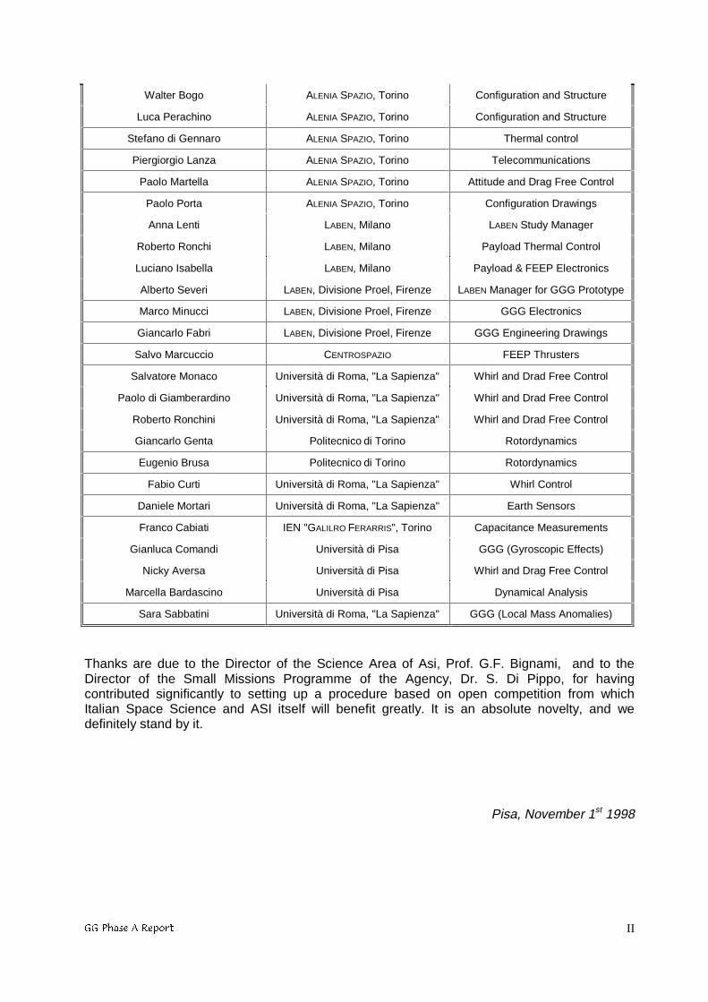
THE GG PHASE A STUDY TEAM
PEOPLE INSTITUTION CONTRIBUTION TO GG
Anna M Nobili Università di Pisa Principal Investigator
Donato Bramanti Università di Pisa Co-Investigator
Erseo Polacco Università di Pisa Co-Investigator
Giovanni Mengali Università di Pisa Dynamical Analysis
Anna Sebasta ASI Study Scientist
Alberto Anselmi ALENIA SPAZIO, Torino ALENIA Study Manager
Giuseppe Catastini ALENIA SPAZIO, Torino Dynamics and Control
Stefano Portigliotti ALENIA SPAZIO, Torino Dynamics and Control
Vittorio Ancona ALENIA SPAZIO, Torino Assembly Integration and Test
**3KDVH$5HSRUW II
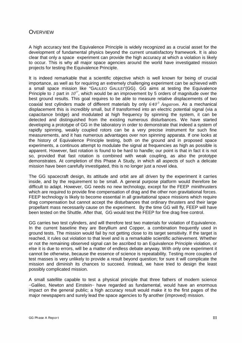
Walter Bogo ALENIA SPAZIO, Torino Configuration and Structure
Luca Perachino ALENIA SPAZIO, Torino Configuration and Structure
Stefano di Gennaro ALENIA SPAZIO, Torino Thermal control
Piergiorgio Lanza ALENIA SPAZIO, Torino Telecommunications
Paolo Martella ALENIA SPAZIO, Torino Attitude and Drag Free Control
Paolo Porta ALENIA SPAZIO, Torino Configuration Drawings
Anna Lenti LABEN, Milano LABEN Study Manager
Roberto Ronchi LABEN, Milano Payload Thermal Control
Luciano Isabella LABEN, Milano Payload & FEEP Electronics
Alberto Severi LABEN, Divisione Proel, Firenze LABEN Manager for GGG Prototype
Marco Minucci LABEN, Divisione Proel, Firenze GGG Electronics
Giancarlo Fabri LABEN, Divisione Proel, Firenze GGG Engineering Drawings
Salvo Marcuccio CENTROSPAZIO FEEP Thrusters
Salvatore Monaco Università di Roma, "La Sapienza" Whirl and Drad Free Control
Paolo di Giamberardino Università di Roma, "La Sapienza" Whirl and Drad Free Control
Roberto Ronchini Università di Roma, "La Sapienza" Whirl and Drad Free Control
Giancarlo Genta Politecnico di Torino Rotordynamics
Eugenio Brusa Politecnico di Torino Rotordynamics
Fabio Curti Università di Roma, "La Sapienza" Whirl Control
Daniele Mortari Università di Roma, "La Sapienza" Earth Sensors
Franco Cabiati IEN "GALILRO FERARRIS", Torino Capacitance Measurements
Gianluca Comandi Università di Pisa GGG (Gyroscopic Effects)
Nicky Aversa Università di Pisa Whirl and Drag Free Control
Marcella Bardascino Università di Pisa Dynamical Analysis
Sara Sabbatini Università di Roma, "La Sapienza" GGG (Local Mass Anomalies)
Thanks are due to the Director of the Science Area of Asi, Prof. G.F. Bignami, and to theDirector of the Small Missions Programme of the Agency, Dr. S. Di Pippo, for havingcontributed significantly to setting up a procedure based on open competition from whichItalian Space Science and ASI itself will benefit greatly. It is an absolute novelty, and wedefinitely stand by it.
Pisa, November 1st 1998
GG Phase A Report III
OVERVIEW
A high accuracy test the Equivalence Principle is widely recognized as a crucial asset for thedevelopment of fundamental physics beyond the current unsatisfactory framework. It is alsoclear that only a space experiment can provide the high accuracy at which a violation is likelyto occur. This is why all major space agencies around the world have investigated missionprojects for testing the Equivalence Principle.
It is indeed remarkable that a scientific objective which is well known for being of crucialimportance, as well as for requiring an extremely challenging experiment can be achieved witha small space mission like “GALILEO GALILEI“(GG). GG aims at testing the EquivalencePrinciple to 1 part in 1017, which would be an improvement by 5 orders of magnitude over thebest ground results. This goal requires to be able to measure relative displacements of twocoaxial test cylinders made of different materials by only 6⋅10-3 Angstrom. As a mechanicaldisplacement this is incredibly small, but if transformed into an electric potential signal (via acapacitance bridge) and modulated at high frequency by spinning the system, it can bedetected and distinguished from the existing numerous disturbances. We have starteddeveloping a prototype of GG in the laboratory in order to demonstrate that indeed a system ofrapidly spinning, weakly coupled rotors can be a very precise instrument for such finemeasurements, and it has numerous advantages over non spinning apparata. If one looks atthe history of Equivalence Principle testing, both on the ground and in proposed spaceexperiments, a continuos attempt to modulate the signal at frequencies as high as possible isapparent. However, fast rotation is found to be hard to handle; our point is that in fact it is notso, provided that fast rotation is combined with weak coupling, as also the prototypedemonstrates. At completion of this Phase A Study, in which all aspects of such a delicatemission have been carefully investigated, this is no longer just a novel idea.
The GG spacecraft design, its attitude and orbit are all driven by the experiment it carriesinside, and by the requirement to be small. A general purpose platform would therefore bedifficult to adapt. However, GG needs no new technology, except for the FEEP minithrusterswhich are required to provide fine compensation of drag and the other non gravitational forces.FEEP technology is likely to become essential in all gravitational space missions which requiredrag compensation but cannot accept the disturbances that ordinary thrusters and their largepropellant mass necessarily cause on the experiment. By the time GG will fly, FEEP will havebeen tested on the Shuttle. After that, GG would test the FEEP for fine drag free control.
GG carries two test cylinders, and will therefore test two materials for violation of Equivalence.In the current baseline they are Beryllium and Copper, a combination frequently used inground tests. The mission would fail by not getting close to its target sensitivity. If the target isreached, it rules out violation to that level and is a remarkable scientific achievement. Whetheror not the remaining observed signal can be ascribed to an Equivalence Principle violation, orelse it is due to errors, will be a matter of endless debate anyway. With only one experiment itcannot be otherwise, because the essence of science is repeatability. Testing more couples oftest masses is very unlikely to provide a result beyond question; for sure it will complicate themission and diminish its chances to succeed. Instead, we have tried to design the leastpossibly complicated mission.
A small satellite capable to test a physical principle that three fathers of modern science− Galileo, Newton and Einstein− have regarded as fundamental, would have an enormousimpact on the general public; a high accuracy result would make it to the first pages of themajor newspapers and surely lead the space agencies to fly another (improved) mission.
**3KDVH$5HSRUW IV
TABLE OF CONTENTS
1. THE SCIENTIFIC SIGNIFICANCE OF GG................................................................................................ 1
1.1 RELEVANCE OF THE EQUIVALENCE PRINCIPLE ............................................................................................ 11.2 THE ADVANTAGES OF SPACE....................................................................................................................... 41.3 HISTORY OF EQUIVALENCE PRINCIPLE TESTING.......................................................................................... 61.4 NOVELTIES AND ADVANTAGES OF THE GG DESIGN .................................................................................. 10
2. THE GG SPACE EXPERIMENT................................................................................................................. 14
2.1 EXPERIMENTAL CONCEPT.......................................................................................................................... 142.1.1 Test Bodies, Expected Signal and PGB Laboratory ........................................................................ 142.1.2 Implications on Spacecraft, Attitude and Orbit .............................................................................. 242.1.3 The Read−out System ...................................................................................................................... 342.1.4 Balancing of the Test Bodies and Common Mode Rejection........................................................... 362.1.5 Self-centering, Whirl Motions and Stabilization.............................................................................. 392.1.6 Locking/Unlocking .......................................................................................................................... 502.1.7 Calibration Procedure..................................................................................................................... 52
2.2 PERTURBATION ANALYSIS, REQUIREMENTS AND ERROR BUDGET............................................................ 542.2.1 Requirements on Drag Compensation and Balancing .................................................................... 542.2.2 Earth Tidal Perturbations ............................................................................................................... 572.2.3 Radiometer Effects and Thermal Requirements .............................................................................. 582.2.4 Electrostatic and Magnetic Effects.................................................................................................. 612.2.5 Coupling to Higher Mass Moments of the Test Bodies ................................................................... 632.2.6 Requirements and Disturbances from Whirl Control ...................................................................... 642.2.7 Thermal Noise and Error Budget .................................................................................................... 65
3. THE GG PAYLOAD PROTOTYPE ON THE GROUND (GGG)............................................................. 68
3.1 THE GOALS................................................................................................................................................ 683.2 SIMILARITIES AND DIFFERENCES WITH THE GG SPACE EXPERIMENT ........................................................ 683.3 THE CONCEPTUAL DESIGN ........................................................................................................................ 703.4 THE APPARATUS........................................................................................................................................ 743.5 STATE AND PERSPECTIVES......................................................................................................................... 81
4. THE GG PAYLOAD...................................................................................................................................... 82
4.1 PAYLOAD CONFIGURATION ....................................................................................................................... 824.2 FEEP THRUSTERS AND CONTROL ELECTRONICS ....................................................................................... 88
4.2.1 FEEP Thrusters............................................................................................................................... 884.2.2 FEEP Control Electronics............................................................................................................... 92
4.3 PAYLOAD ELECTRONICS............................................................................................................................ 954.3.1 Payload Control Electronics Architecture ...................................................................................... 954.3.2 Payload Data Processor Architecture........................................................................................... 101
4.4 THERMAL CONTROL OF THE SCIENTIFIC PAYLOAD.................................................................................. 1054.4.1 Thermal Requirements................................................................................................................... 1054.4.2 Thermal Control Solutions ............................................................................................................ 1054.4.3 Estimation of the Orbital Heat Fluxes........................................................................................... 1064.4.4 Thermal Models............................................................................................................................. 1074.4.5 Analyses and Results ..................................................................................................................... 1074.4.6 Conclusions ................................................................................................................................... 109
5. THE GG SATELLITE ................................................................................................................................. 110
5.1 LAUNCH REQUIREMENTS AND CONSTRAINTS.......................................................................................... 1105.2 SATELLITE CONFIGURATION.................................................................................................................... 1125.3 MECHANICAL DESIGN.............................................................................................................................. 120
5.3.1 Structural Design .......................................................................................................................... 1205.3.2 Launcher Mechanical Requirements ............................................................................................. 120
**3KDVH$5HSRUW7$%/(2)&217(176
**3KDVH$5HSRUW V
5.3.3 Materials Selection And Properties............................................................................................... 1215.3.4 Structural Mass Budget ................................................................................................................. 1225.3.5 Finite Element Model and Structural Analysis.............................................................................. 123
5.4 SPACECRAFT THERMAL CONTROL........................................................................................................... 1285.4.1 Thermal Control Subsystem (TCS) Requirements ......................................................................... 1285.4.2 TCS Concept And Configuration................................................................................................... 1285.4.3 TCS Performance .......................................................................................................................... 1315.4.4 Conclusions and Critical Areas..................................................................................................... 133
5.5 SPACECRAFT ATTITUDE CONTROL .......................................................................................................... 1355.6 ON BOARD DATA HANDLING................................................................................................................... 1405.7 TRACKING, TELEMETRY AND COMMAND ................................................................................................ 1425.8 POWER SUPPLY........................................................................................................................................ 1445.9 SATELLITE BUDGETS ............................................................................................................................... 146
6. STABILIZATION AND DRAG FREE CONTROL.................................................................................. 147
6.1 THEORETICAL ANALYSIS AND CONTROL LAWS....................................................................................... 1476.1.1 Mass Properties............................................................................................................................. 1486.1.2 Geometrical Properties ................................................................................................................. 1496.1.3 Sensors .......................................................................................................................................... 1496.1.4 Actuators and Function Generators. Definition of External Disturbance..................................... 1496.1.5 Passive Devices ............................................................................................................................. 1506.1.6 Active Devices (User Defined) ...................................................................................................... 1526.1.7 Controller ...................................................................................................................................... 1536.1.8 Interconnets ................................................................................................................................... 1536.1.9 Constant Data (CNTDTA) ............................................................................................................. 1536.1.10 Eigenfrequencies ........................................................................................................................... 1546.1.11 Whirling Stabilization.................................................................................................................... 1556.1.12 Whirling Stabilization Control Law............................................................................................... 1566.1.13 Non Rotating Damping in Pulsed Mode........................................................................................ 1636.1.14 2-Body and 6-Body results ............................................................................................................ 1656.1.15 Drag Free Control......................................................................................................................... 177
7. MISSION OPERATIONS AND GROUND CONTROL .......................................................................... 182
7.1 MISSION OPERATIONS CONCEPT.............................................................................................................. 1827.2 INITIALISATION, CALIBRATION AND CONTROL........................................................................................ 1827.3 SCIENTIFIC DATA MANAGEMENT ............................................................................................................ 184
8. GG PROGRAMME DEVELOPMENT APPROACH .................................................................................. 186
8.1 SATELLITE DEVELOPMENT APPROACH .................................................................................................... 1868.1.1 Programme Logic ........................................................................................................................... 1868.1.2 Development Approach................................................................................................................... 186
8.2 ELECTRICAL AND MECHANICAL GROUND SUPPORT EQUIPMENT............................................................. 1918.3 TECHNOLOGICAL REQUIREMENTS ................................................................................................................ 193
REFERENCES i
**3KDVH$5HSRUW&KDSWHU 1
1. THE SCIENTIFIC SIGNIFICANCE OF GG
1.1 RELEVANCE OF THE EQUIVALENCE PRINCIPLE
“GALILEO GALILEI” (GG) is a small satellite project devoted to testing the EQUIVALENCEPRINCIPLE (EP) to 1 part in 1017, an improvement by 5 orders of magnitude over the best resultsobtained so far on Earth. It is the same target of the STEP mission proposal as evaluated twiceby ESA at Phase A level within the competitions for the medium size missions M2 (Blaser etal., 1993) and M3 (Blaser et al., 1996).
Do bodies of different composition fall with the same acceleration in a gravitational field? If not,the so called Equivalence Principle is violated. The Equivalence Principle, expressed byGalileo and later reformulated by Newton, was assumed by Einstein as the founding Principleof general relativity, the best theory of gravitation available so far. In fact, it is not a Principlebut a starting hypothesis unique to Gravity: no Equivalence Principle holds for the otherfundamental forces of nature (the electromagnetic, weak and strong interaction) and almost alltheories trying to unify gravity with these forces require the Equivalence Principle to beviolated, thus indicating that general relativity may not be the final truth on gravitation, just asNewton’s theory of gravitation was proved by Einstein not to be the final truth at beginning ofthis century. All tests of general relativity, except those on the Equivalence Principle, areconcerned with specific predictions of the theory; instead, EP tests probe the basicassumption of general relativity, and this is why they are a much more powerful instrument ofinvestigation. A high accuracy, unquestionable, experimental result on the EquivalencePrinciple −no matter whether it is violated or confirmed− will be a crucial asset for manydecades to come. And this is how it has to be, because physics is an experimental science inwhich any theory, in spite of its internal consistency and beauty, has to confront experiments,and ultimately will stand or fall depending solely on experimental results.
Galileo questioned Aristotle’s statement that heavier bodies should fall faster than lighter ones,arguing instead that all bodies fall at equal speeds regardless of their mass and composition(this is the Universality of Free Fall). His formulation of the universality of free fall, which latelybecame known as the Equivalence Principle, was first published in 1638 “…veduto, dicoquesto, cascai in opinione che se si levasse totalmente la resistenza del mezzo, tutte lematerie descenderebbero con eguali velocità “ (“... having observed this I came to theconclusion that, if one could totally remove the resistance of the medium, all substances wouldfall at equal speeds ”). It appeared in his Discorsi e dimostrazioni matematiche intorno a duenuove scienze attinenti alla meccanica e ai movimenti locali, which was published outside Italy(in Leiden) few years after completion due to Galileo’s prosecution by the Church of Rome(Galileo, Le Opere, Vol. VIII, 1968 Edition). Aged 74, Galileo was blind and under house arrest;but the 'LVFRUVL are based on much earlier work, mostly on experiments with the inclinedplane and the pendulum going back almost 40 years to the time when he was a young lecturerat the University of Pisa or had just moved to Padova. Galileo was well aware thatexperiments he made with inclined plane and pendula were much more accurate than justdropping masses from a tower; but mass dropping experiments allowed him to describe theuniversality of free fall in a very straightforward manner, not requiring a deep understanding ofmechanics. This is how Galileo has become known worldwide for his mass droppingexperiments. Indeed, no image of science has captured the imagination of ordinary peoplemore than that of Galileo dropping masses from the leaning tower of Pisa, a symbol of the birthof the modern scientific method.
About 80 years after Galileo's first experiments Newton went further, actually recognizing theproportionality of PDVV and ZHLJKW. Newton regarded this proportionality as so important thathe devoted to it the opening paragraph of the Principia (Cajori Edition, 1934) where he stated“ This quantity that I mean hereafter under the name of ... mass ... is known by the weight ...
**3KDVH$5HSRUW&KDSWHU7+(6&,(17,),&6,*1,),&$1&(2)**
**3KDVH$5HSRUW&KDSWHU 2
for it is proportional to the weight as I have found by experiments on pendulums, veryaccurately made... ’’ . At the beginning of the 20th century, almost 300 years since Galileo’swork, Einstein realized that because of the proportionality between the gravitational (passive)mass mg and the inertial mass mi, the effect of gravitation is locally equivalent to the effect of anaccelerated frame and can be locally cancelled: this is known as the Weak EquivalencePrinciple which Einstein introduced in 1907 (Einstein, 1907) as the hypothesis of completephysical equivalence between a gravitational field and an accelerated reference frame: in afreely falling system all masses fall equally fast, hence gravitational acceleration has no localdynamical effects. Einstein then generalized this principle to theStrong Equivalence Principle,on which he based his theory of general relativity. The Strong Equivalence Principle states thatin an electromagnetically shielded laboratory, freely falling and non rotating, the laws ofphysics −including their numerical content− are independent of the location of the laboratory. Insuch a laboratory all particles free of non gravitational forces move with the same acceleration.Therefore, according to Einstein, the effects of gravity are equivalent to the effects of living in acurved space-time. In this sense the Equivalence Principle expresses the very essence ofGeneral Relativity and as such it deserves to be tested as accurately as possible. In the last 30years since the advent of the space age general relativity has been subject to extensiveexperimental testing as never before in its first 50 years of existence, and so far it has comeout having no real competitors; the crucial area where experimental gravitation is likely to playan important role is in the verification of the universality of free fall as a test of the weakequivalence principle itself, since it is tantamount to testing whether gravitation can beascribed to a metric structure of space-time.
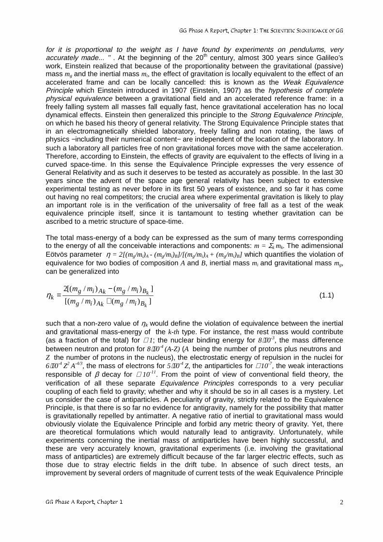
The total mass-energy of a body can be expressed as the sum of many terms correspondingto the energy of all the conceivable interactions and components: m = Σk mk. The adimensionalEötvös parameter η = 2[(mg/mi)A - (mg/mi)B]/[(mg/mi)A + (mg/mi)B] which quantifies the violation ofequivalence for two bodies of composition A and B, inertial mass mi and gravitational mass mg,can be generalized into
])/()/[(
])/()/[(2
k
k
BigkAig
BigkAigk mmmm
mmmm
+−
=η (1.1)
such that a non-zero value of ηk would define the violation of equivalence between the inertialand gravitational mass-energy of the k-th type. For instance, the rest mass would contribute(as a fraction of the total) for ≅ 1; the nuclear binding energy for 8⋅10-3, the mass differencebetween neutron and proton for 8⋅10-4 (A-Z) (A being the number of protons plus neutrons and Z the number of protons in the nucleus), the electrostatic energy of repulsion in the nuclei for6⋅10-4 Z2 A-4/3, the mass of electrons for 5⋅10-4 Z, the antiparticles for ≅ 10-7, the weak interactionsresponsible of β decay for ≅ 10-11. From the point of view of conventional field theory, theverification of all these separate Equivalence Principles corresponds to a very peculiarcoupling of each field to gravity; whether and why it should be so in all cases is a mystery. Letus consider the case of antiparticles. A peculiarity of gravity, strictly related to the EquivalencePrinciple, is that there is so far no evidence for antigravity, namely for the possibility that matteris gravitationally repelled by antimatter. A negative ratio of inertial to gravitational mass wouldobviously violate the Equivalence Principle and forbid any metric theory of gravity. Yet, thereare theoretical formulations which would naturally lead to antigravity. Unfortunately, whileexperiments concerning the inertial mass of antiparticles have been highly successful, andthese are very accurately known, gravitational experiments (i.e. involving the gravitationalmass of antiparticles) are extremely difficult because of the far larger electric effects, such asthose due to stray electric fields in the drift tube. In absence of such direct tests, animprovement by several orders of magnitude of current tests of the weak Equivalence Principle
**3KDVH$5HSRUW&KDSWHU7+(6&,(17,),&6,*1,),&$1&(2)**
**3KDVH$5HSRUW&KDSWHU 3
with ordinary matter would also be an important constraint as far as the relation betweengravity and antimatter is concerned.
Nearly all attempts to extend the present framework of physics predict the existence of newinteractions which are composition dependent and therefore violate the Equivalence Principle.Equivalence Principle tests are by far the most sensitive low energy probes of such newphysics beyond the present framework. This is because any deviation from the universality offree fall −expressed as a fractional differential acceleration ∆a/a between falling bodies ofdifferent composition− is proportional to the post-Newtonian deviations from general relativitymeasured, for instance, by the adimensional parameter γ*≡ γ -1 (γ the Eddington parameter)with a proportionality factor <<1 (from 10-5 to 10-3 depending on scalar or vector models).Therefore, while γ* is constrained by post-Newtonian or pulsar tests below 10-3, the currentground results on the Equivalence Principle giving ∆a/a ≤ 10-12 already constrain γ* below 10-7
or 10-9, which clearly shows the superior probing power of Equivalence Principle tests.
No precise target accuracy at which a violation should occur has been predicted by thesetheories; an EP violation is expected, but only below the 10-12 level reached so far, probablywell below it; whether this is really so, only high accuracy experiments can tell.
**3KDVH$5HSRUW&KDSWHU7+(6&,(17,),&6,*1,),&$1&(2)**
**3KDVH$5HSRUW&KDSWHU 4
1.2 THE ADVANTAGES OF SPACE
There is a tendency in ground physics experiments, as well as in facilities for astronomicalobservations, to become big enterprises involving many scientists/engineers and large funding,often lasting many years. By contrast, scientific space missions tend to become smaller, fasterand cheaper; so the gap between the two is decreasing. Yet, doing science in space is still achallenge in itself. Therefore, no space experiment should be proposed unless there is a verygood reason for it to be done in space. As far as testing the Equivalence Principle isconcerned, the crucial advantage of a space experiment in low Earth orbit (in essence two testbodies of different composition in the gravitational field of the Earth and a read-out system tomonitor their relative displacements) is that the driving signal (over distances of the order ofthe radius of the Earth) is given by the entire value of the Earth gravitational acceleration,yielding a (differential) signal acceleration:
η⋅+
=⊕
⊕2)( hR
GMaEP (1.2)
for an EP violation of level η (the adimensional Eötvös parameter) and an orbiting altitude haround the Earth (G is the universal constant of gravity, M⊕ , R⊕ are the mass and radius of theEarth). The driving acceleration from the Earth is therefore GM⊕/(R⊕+h)2, whose value, at lowaltitudes, is close to 1-g (8.4 m/sec2 for h ≅ 520 km). If the test bodies, rather than orbiting aroundthe Earth are suspended on its surface, the maximum strength of the driving signal (at 45°latitude) is only about 1.69⋅10-2 m/sec2; if the Sun is taken as a source rather than the Earth, thecorresponding driving signal is even weaker: ≅ 6⋅10-3 m/sec2 at most (see Sec. 3.2). With adriving signal almost 3 orders of magnitude stronger, the advantage of testing the EquivalencePrinciple in space is unquestionable. By contrast, a short range EP experiment has nothing togain from going into space since much bigger source masses can be used on the ground.
In the early days of the space age ordinary people and scientists alike dreamed of going intospace. Physicists in particular were fascinated by the emptiness and quietness of space, whichappeared to be the ideal environment for many experiments, especially gravity experiments,limited by too many disturbances on Earth. As dreams faded away and reality began, itbecame apparent that space is not empty and spacecraft are not quiet; at least, not as much toautomatically compensate for the disadvantage of the experiment becoming inaccessible toone’s hands.
Nowadays the space environment is far better understood, and a few statements can be madewhich are not likely to be disproved. The absence of seismic noise can no longer be quoted asa reason for moving to space, since on-board of any space structure there is vibration noiseinstead, while down on Earth experimentalists have learned how to cope with seismic noisevery effectively. Also, space in far from being empty: residual atmosphere (in low Earth orbits),photons from solar radiation, charged particles ... make physics experiments in space−particularly gravitational ones− far from straightforward. However, the main advantage ofspace is still there: the gravitational attraction of the Earth is largely compensated by thecentrifugal force due to the orbital motion of the spacecraft and there is no such thing like theg ≅ 10 m/sec2 local acceleration of gravity that shapes our everyday life on Earth by giving aZHLJKW to every object. In addition and more importantly, the largest acceleration on-board ismany orders of magnitude smaller than 1-g: how much depends on the orbit, the spacecraft,the body on-board that we are considering (e.g. whether it is suspended or free floating, orelse rigidly connected to the spacecraft, whether it is close to the center of mass of thespacecraft or far away from it). Inside GG the largest acceleration −even not considering active
**3KDVH$5HSRUW&KDSWHU7+(6&,(17,),&6,*1,),&$1&(2)**
**3KDVH$5HSRUW&KDSWHU 5
drag compensation− is about a factor 108 smaller than 1-g. Evidently a ratio by one hundredmillion times between the force that has to be overcome in order to suspend the same body ina ground laboratory or inside the GG spacecraft makes a big difference in the problems to befaced; it is indeed possible to suspend 100 kg in the spacecraft with the same suspensions thatwould be used on Earth for suspending 1 milligram. Weightlessness, not the absence ofseismic noise, is therefore the true advantage of space that must be exploited. GG has beenspecifically designed for weightlessness to provide numerous advantages: weak mechanicalcoupling, self-centering and balancing of the test bodies, electrical grounding, vibrationisolation; all of them crucial for a sensitive EP experiment, and all of them deriving from theabsence of weight in space.
An EP space experiment in low Earth orbit offers the crucial advantage of a signal about afactor of a thousand bigger than on Earth (see Sec. 3.2); the challenge of a fully automatedremote controlled experiment can be traded off against the advantages of weightlessness. Anaccuracy of 1 part in 1017 in EP testing means five orders of magnitude improvement withrespect to the best ground results. Even with further progress in ground experiments (e.g. toan accuracy of 1 part in 1013, possibly 1014) a space mission would undoubtedly mean a greatleap forward allowing space scientists to probe a totally unknown, highly promising field ofphysics like no other ground experiment can even dream of.
**3KDVH$5HSRUW&KDSWHU7+(6&,(17,),&6,*1,),&$1&(2)**
**3KDVH$5HSRUW&KDSWHU 6
1.3 HISTORY OF EQUIVALENCE PRINCIPLE TESTING
Aristotle’s statement that heavier bodies should fall faster than lighter ones was alreadyquestioned in the 6th century by Philoponus, who noted that: if two bodies are released by thesame altitude one can observe that the ratio of the times of fall of the bodies does not dependon the ratio of their weights, and the difference of the times is very small. Amazingly enough, itwas only in 1553 that Benedetti reconsidered the issue, stating that the velocity of fall does notdepend on the weights of the falling bodies.
Galileo questioned Aristotle’s view and even showed the internal contradiction of Aristotle’sreasoning with a simple argument which goes as follows: If then we take two bodies whosenatural speeds are different, it is clear that on uniting the two, the more rapid one will partly beretarded by the slower, and the slower will be somewhat hastened by the swifter….Hence theheavier body (made by the two tied together) moves with less speed than the lighter (theformer swifter one) an effect which is contrary to your (by Aristotle) supposition. Moreimportantly, Galileo was well aware of the need to provide experimental evidence. By droppingbodies of different composition in media much denser than air Galileo came to the conclusionthat all bodies fall equally fast and that any observed difference is due to the differentresistance of the medium that different bodies are subject to. Galileo was also aware of thedifficulty to prove this fact by dropping masses from a height. As he clearly argues in the'LVFRUVL, from a big height the accumulated effect of air resistance is too large to allow areliable conclusion, while from a small one any difference is too small to appreciate. Mostprobably Galileo was not able to calculate precisely the effect of air resistance, but he certainlyknew that it was much smaller if the velocity of the body was small (we know it is proportionalto the velocity squared). He therefore performed experiments with bodies falling on inclinedplanes where only a fraction of the gravitational acceleration is relevant, which reduces thefalling velocity −hence also the effect of air resistance.
Better still than bodies falling on inclined planes are bodies suspended from a wire and broughtto oscillation like a pendulum: if all bodies fall with the same acceleration in the gravitationalfield of the Earth, bodies suspended from wires of the same length which are released at thesame time by the same angle must keep in step regardless of their mass or composition.Besides reducing the velocity −and air resistance− the periodic repetition of the motion allowsa better measurement and improves the accuracy of the experiment. …e finalmente ho presodue palle, una di piombo e una di sughero, quella ben più di cento volte più grave di questa, eciascheduna di loro ho attaccata a due sottili spaghetti eguali, lunghi quattro o cinque braccia,legati ad alto; allontanata poi l’una e l’altra palla dallo stato perpendicolare, gli ho dato l’andarenell’istesso momento, ed esse, scendendo per le circonferenze de’ cerchi descritti da glispaghi eguali, lor semidiametri, passate oltre al perpendicolo, son poi per le medesime straderitornate indietro e reiterando ben cento volte per lor medesime le andate e le tornate, hannosensatamente mostrato, come la grave va talmente sotto il tempo della leggiera, che né in bencento vibrazioni, né in mille, anticipa il tempo d’un minuto secondo, ma camminano con passoegualissimo.
Pendulum experiments have provided the most accurate tests of the Equivalence Principle tillthe torsion balance was used for EP testing at the beginning of 1900. Newton is often reportedas the first ever to perform pendulum tests of the Equivalence Experiment; in fact, Galileo’spendulum experiments as in the above quotation from the Discorsi had even been reportedmuch earlier than the publication of the Discorsi, in a letter addressed by Galileo to Guidobaldodal Monte in 1602 (Le Opere, Vol. X, 1968 Edition). It is sometimes argued that Galileo couldnot perform accurate pendulum tests of the Equivalence Principle because −although he haddiscovered the physical properties of the pendulum− he did not have an accurate pendulum
**3KDVH$5HSRUW&KDSWHU7+(6&,(17,),&6,*1,),&$1&(2)**
**3KDVH$5HSRUW&KDSWHU 7
clock, which was invented by Christian Huygens after Galileo’s death, in 1657. Huygens clockwas obviously available to Newton. The point is, however, that pendulum tests of theEquivalence Principle do not require a clock: the oscillating bodies must keep in step, and onlydifferences between the two matter, not the precise value of the oscillation period. Newtonquotes his pendulum tests of the Equivalence Principle to have an accuracy of 1 part in 103.The pendulum tests described by Galileo have been repeated by Fuligni and Iafolla (1993).They concluded that even without special care it is easy to reach an accuracy of 1 part in 103;an error by 0.1% in the length of the suspensions is a realistic assumption, yielding a similaraccuracy for the outcome of the experiment, and this is in agreement with Galileo’sobservation that the bodies keep in step for hundred or even thousands swings.
Experiments to test the Equivalence Principle require to measure a differential effect betweenthe test bodies; a pendulum experiment is better than a mass dropping experiment because itmakes it easier to record differences, but it is not a null experiment. An apparatus for EPtesting should be differential by its own design, i.e. such that it gives a non-zero signal only incase of violation; otherwise it should give a null result. The torsion balance is one suchdifferential device: two objects of different composition are connected by a rod and suspendedin a horizontal orientation by a thin wire. Any suspended body is subject to the gravitationalattraction of the Earth and to the centrifugal force due to the Earth daily rotation about its axis.In the horizontal plane the two reach equilibrium along the North-South direction. Thegravitational attraction is proportional to the gravitational mass mg, while the centrifugal force isproportional to the inertial mass mi. If the ratio mg/mi is different for the two bodies of the torsionbalance there is differential force in the North-South direction; with the rod of the balancealigned along the East-West direction the entire differential force gives a torque tending to twistthe torsion balance. The differential force and its torque are constant; by exchanging thebodies on the balance (or rotating the apparatus by 180° ), the sense of twist should reverse. Ifthe ratio mg/mi is the same for the two bodies (no violation) the torsion balance should give notwist (null result).
The first careful tests of the Equivalence Principle with a torsion balance were performed overmany years at the beginning of this century by Roland von Eötvös and his colleagues inBudapest. Their results were published three years after Eötvös’ death (Eötvös et al., 1922)and more details on the apparatus and methods of measurement appeared in Eötvös’collected works (Eötvös, 1953); the experiments were later repeated by Renner (1935) usingEötvös’ apparatus. Most precise experiments are null experiments, and the Eötvös experimentis no exception: they reported no EP violation to the level of several parts in 109, an accuracymuch better than in all previous experiments.
Eötvös results have remained unchallenged until the 60’s, when an Eötvös-type experimentwas performed in Princeton (Roll et al. 1964) with an essential novelty. On the footsteps ofEötvös outstanding results the Princeton scientists led by Robert Dicke also used a torsionbalance. However, Eötvös original experiment, despite its high quality, has an essentialweakness: the signal is a constant twist produced by a constant torque (DC effect), hence theexperiment lacks a suitable control, for there is no way of turning off the centrifugal force of theEarth’s diurnal rotation. Only a 180° rotation of the apparatus by the experimentalists (with theinevitable consequence of disturbing the delicate balance) gives the signal a signature. Dickesuggested to look at the acceleration of the apparatus towards the Sun, rather than the Earth,and compare it with the centrifugal force due to the annual rotation of the Earth around theSun. Were the ratio mg/mi different for the weights of the balance, an anomalous torque wouldappear; at 6 a.m. and 6 p.m., and for a torsion balance beam in the North-South direction, ananomalous gravitational pull upon one of the weights at an end of the beam would produce aturning force. The resulting twist would be periodic with a 24-hr period (the solar day) due tothe diurnal rotation of the Earth. The horizontal component of the acceleration towards the Sun
**3KDVH$5HSRUW&KDSWHU7+(6&,(17,),&6,*1,),&$1&(2)**
**3KDVH$5HSRUW&KDSWHU 8
(as well as of the annual centrifugal acceleration) is −at most− 3/8 of the diurnal centrifugalacceleration, but it is modulated by the rotation of the Earth with a 24-hr period and thereforethe measurement contains its own zero check. Thanks to this frequency modulation and inspite of the weaker signal Roll et al. (1964) improved significantly Eötvös result, finding no EPviolation to about 1 part in 1011 for aluminum and gold. Braginsky and Panov (1973) also usedthe Sun as a source and the modulation of the Earth’s rotation. They improved the experimentfurther using 8 masses (of aluminum and platinum) at the vertices of an octagon, instead oftwo. The torsion-balance experiment being a small force experiment, any spurious gravitationalfield due to nearby masses can cause significant disturbances. The geometrical structurerealized by Braginsky and Panov is less sensitive to the effects of such fields, since only agravitational potential with a non-zero fifth derivative does affect their balance. The result oftheir experiment is that the inertial and gravitational mass (for aluminum and platinum) are thesame to about 1 part in 1012.
The advantage of a space experiment (with a much stronger signal) was recognized soon afterthe beginning of the space age. While designing a space experiment scientists also tried toprovide a frequency modulation. Chapman and Hanson (1970) proposed to test theEquivalence Principle in space using a fast rotating platform so as to modulate the signal at itsrotating frequency; however, in their apparatus the test bodies were constrained to move alongone diameter of the rotating platform, and it is well known that any such rotating system isalways strongly unstable above the critical speed (Den Hartog, 1985). Worden and Everitt(1973) proposed instead that the orbital motion of the spacecraft enclosing the test bodieswould provide the modulation. This requires the spacecraft (which carries the coaxial testcylinders) to be kept fixed with respect to inertial space by accurate active control. This is theSTEP proposal (Worden and Everitt, 1973; Worden, 1976; Worden, 1987; Blaser et al., 1993;Blaser et al. 1996). The symmetry axis of the test cylinders is the sensitive axis, and lies in theorbital plane (the system is very stiff in the plane perpendicularly to the symmetry axis). If onecylinder is attracted by the Earth more than the other there is a relative movement of the twoone inside the other; the effect is maximum when the symmetry axis is directed towards thecenter of the Earth (changing sign as the satellite moves by 180° around the Earth) and it iszero when the symmetry axis is perpendicular to the satellite-to-Earth direction. Hence, thesignal has an intensity varying at the orbital frequency of the satellite (corresponding to aperiod, in low Earth orbit, of about 6,000 sec). Any higher frequency signature, higher than theorbital frequency, that one would wish to impress on the signal requires the spacecraft to bespun around its actively controlled space-fixed attitude. Due to the STEP design these canonly be slow rotations and require a careful active control.
In the meantime scientists have achieved a higher frequency modulation of the putative EPviolation signal in classical torsion balance experiments where the apparatus is mounted on aturntable that rotates with a period of 1÷2 hr. These are the very careful EP experiments by the“Eöt-Wash" group at the University of Seattle (Su et al., 1994) whose results are at presentthe most accurate (to about 1 part in 1012). Their modulation frequency is the highest achievedso far, and their ongoing attempts to improve the sensitivity by one order of magnitude includea faster and smoother rotation of the turntable. The only alternative to attempting fasterrotation is pursued by the R. Cowsik group in India, with a much heavier torsion balance in avery low noise environment (25 m under the ground) and a very good thermal stability (bymeans of two, very large, concentric vacuum chambers) (Unnikrishnan, 1994; Cowsik et al.,1997)
It is apparent how all EP differential experiments based on the direct measurement ofextremely small displacements between two test bodies have been driven, in Earth-basedexperiments as well as in space proposals, by the need to provide a modulation frequency ofthe expected tiny signal at the highest possible frequency. GG tries to go much beyond in thistrend by modulating the signal at 2 Hz, an increase by more than a factor 104 in comparison to
**3KDVH$5HSRUW&KDSWHU7+(6&,(17,),&6,*1,),&$1&(2)**
**3KDVH$5HSRUW&KDSWHU 9
all previous experiments. A modulation frequency of ≅ 1 Hz has been proposed also for anEquivalence Principle experiment inside a capsule in sub-orbital flight with a free falling timeof ≅ 30 sec (Lorenzini et al., 1994; Iafolla et al.,1998).
Surprisingly enough, completely different tests of the Equivalence Principle (for the Earth andthe Moon falling towards the Sun) have achieved an accuracy close to that of torsion balanceexperiments, even about one order of magnitude better (Dickey et al. 1994; Williams et al.,1996). The Earth−Moon distance is measured by lunar laser ranging (LLR) to the corner cubelaser reflectors left by the astronauts on the surface of the Moon, accurate to better than 1 cm.Were the Earth and the Moon to be attracted differently by the Sun because of their differentcomposition (1/3 iron core and 2/3 silicate mantle the Earth; entirely silicate mantle the Moon),a physical model based on conventional Newtonian gravity with general relativistic correctionswould not be able to make predictions reconcilable with the observed LLR data. This is a testof the Equivalence Principle for different composition, but also for gravitational self−energyeffects in the Earth (testing gravity’s pull on gravitational energy), effects which are obviouslyabsent in test bodies of laboratory size. According to Einstein, all forms of matter and energy,including the gravitational binding energy, accelerate at the same rate in a uniform gravitationalfield, and the gravitational binding energy of the earth amounts to 5⋅10-10 of its mass and istherefore not negligible to the current achieved accuracy. However, it should be emphasizedthat −despite the high quality of the analysis− LLR tests of the Equivalence Principle are basedon highly complex physical models of many perturbing effects on the orbit of the Moon (suchas tides) whose signature can be the same as that of an EP violation, and which involve manyunknown parameters to be adjusted. To the contrary, EP experiments with test bodies oflaboratory size can always provide a zero check: no sensitivity can be claimed better than theone which is obtained using in the same apparatus test bodies of the same composition.
**3KDVH$5HSRUW&KDSWHU7+(6&,(17,),&6,*1,),&$1&(2)**
**3KDVH$5HSRUW&KDSWHU 10
1.4 NOVELTIES AND ADVANTAGES OF THE GG DESIGN
A torsion balance is not well suited for testing the Equivalence Principle in space, wherescientists agree to use coaxial test cylinders, with a read out system to detect relativedisplacements between them. The main novelty of GG is to modulate the expected EPviolation signal by spinning the entire spacecraft (also of cylindrical symmetry, enclosing thetest bodies and the read−out sensors) at 2 Hz, which in addition provides 1-axis passivestabilization of the satellite.
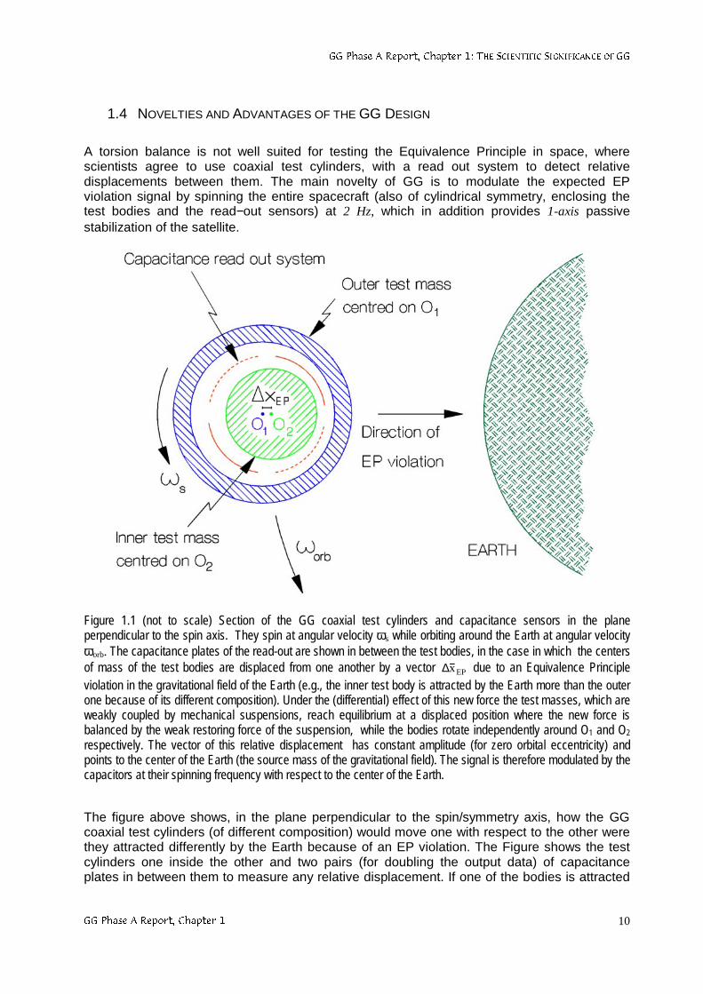
Figure 1.1 (not to scale) Section of the GG coaxial test cylinders and capacitance sensors in the planeperpendicular to the spin axis. They spin at angular velocity ωs while orbiting around the Earth at angular velocityωorb. The capacitance plates of the read-out are shown in between the test bodies, in the case in which the centersof mass of the test bodies are displaced from one another by a vector EPx
r∆ due to an Equivalence Principleviolation in the gravitational field of the Earth (e.g., the inner test body is attracted by the Earth more than the outerone because of its different composition). Under the (differential) effect of this new force the test masses, which areweakly coupled by mechanical suspensions, reach equilibrium at a displaced position where the new force isbalanced by the weak restoring force of the suspension, while the bodies rotate independently around O1 and O2
respectively. The vector of this relative displacement has constant amplitude (for zero orbital eccentricity) andpoints to the center of the Earth (the source mass of the gravitational field). The signal is therefore modulated by thecapacitors at their spinning frequency with respect to the center of the Earth.
The figure above shows, in the plane perpendicular to the spin/symmetry axis, how the GGcoaxial test cylinders (of different composition) would move one with respect to the other werethey attracted differently by the Earth because of an EP violation. The Figure shows the testcylinders one inside the other and two pairs (for doubling the output data) of capacitanceplates in between them to measure any relative displacement. If one of the bodies is attracted

**3KDVH$5HSRUW&KDSWHU7+(6&,(17,),&6,*1,),&$1&(2)**
**3KDVH$5HSRUW&KDSWHU 11
by the Earth more than the other, the two centers of mass move away from one anotheralways towards the center of the Earth. In GG the test cylinders are coupled by very weakmechanical suspensions so that even a tiny differential force (in the plane perpendicular to thespin/symmetry axis) causes a mechanical displacement which is detectable once transformedinto an electric potential signal by the capacitance read-out. The weaker the coupling, thelonger the natural period of differential oscillations of the test bodies, the more sensitive thesystem is to differential forces such as the one caused by an EP violation. It is apparent fromFig. 1.1 that spinning capacitance plates modulate the amplitude of the electrical signal causedby an EP violation at their spinning frequency with respect to the Earth (2 Hz in the currentbaseline), with a well defined phase (the vector does always point towards the center of theEarth). In absence of spin the EP violation force has constant intensity (except for the effect oforbital eccentricity of the satellite, which is close to zero) and a direction changing at the orbitalfrequency of the satellite around the Earth (≅ 1.75⋅10-4 Hz); so in GG the electric signal ismodulated at a frequency about 104 times higher than the frequency of the EP violation force,the advantage being the reduction of low frequency noise both mechanical (the suspensionshave higher mechanical quality factor Q at higher frequency) and electrical (lower 1/felectronic noise). The spinning state of the GG spacecraft is a stable 1-axis rotation and needsno active control.
An important consequence of the fact that in GG the expected EP violation force lies in theplane normal to the spin/symmetry axis of the test cylinders is that a major perturbation dueto the so called "radiometer effect" is zero also at room temperature. It is known that, in lowpressure conditions where the mean free path of the gas particles is much larger than thedimensions of the vessel, a cylinder whose faces are not at the same temperature is subject toan acceleration along its symmetry axis whose value is exceedingly large unless the residualgas pressure is extremely low, down to values which can only be obtained at very lowtemperatures. In STEP this radiometer effect along the symmetry/sensitive axis of the testcylinders competes directly with the signal, and is reduced thanks to the extremely low level ofresidual pressure, which can be obtained by operation at superfluid He temperature (about 2K). Instead, a hollow cylinder whose inner and outer surfaces were not exactly at the sametemperature, would have zero radiometer effect in the plane perpendicular to its axis, for puresymmetry reasons. In reality, azimuth asymmetries as well as the radiometer effect along thesymmetry axis of the cylinders must be taken into account in GG, since it is a non cryogenicexperiment; however, the requirements they impose on the amount of acceptable temperaturegradients are compatible with a pure passive thermal control of the GG experimentalapparatus (see Sec. 2.2.3). If the radiometer effect is dealt with at room temperature, one ofthe main reasons why a high accuracy EP experiment in space should be operated incryogenic conditions is no longer valid.
Low temperature is certainly helpful in reducing thermal noise. Since the dependence ofthermal noise acceleration on the experiment temperature T and the mass m of the test bodiesis ∝(T/m)1/2, in GG we use more massive test bodies: test masses of 10 kg each at 300 K, as wehave in GG, result in the same thermal noise as with test masses of 0.1 kg at a temperature of3 K. However, a future, lower temperature version of the GG experiment can be envisaged forwhich the rapid spin gives an important advantage: the very high centrifugal force at theperiphery of the spacecraft would dominate the motion of the refrigerating (movable) materialand largely reduce, by symmetry, its perturbations on the bulk of the experiment; evaporationcan take place along the spin axis for symmetry reasons too. This is unlike non-spinning orslowly spinning satellite experiments for EP testing in which perturbations from the nearbyrefrigerant mass (a few hundred liters of He in STEP) is known to be a serious source ofperturbation.
The weak mechanical coupling of the GG test bodies (e.g. obtained with a simple and effectiveuse of helical springs and flat gimbals pivoted on thin torsion wires) is the key feature which
**3KDVH$5HSRUW&KDSWHU7+(6&,(17,),&6,*1,),&$1&(2)**
**3KDVH$5HSRUW&KDSWHU 12
allows us to cope with a major dangerous effect: the effect of residual air drag along thesatellite orbit. Air resistance acting on the spacecraft surface is experienced by the test bodiessuspended inside it as a translational inertial acceleration equal and opposite to the onecaused by air drag on the center of mass of the whole satellite (spin axes are stable due to theextremely high energy of spin). This acceleration is about 8 orders of magnitude weaker than1-g on Earth but about as many orders of magnitude larger than the expected signal; it shouldbe the same on both test cylinders, but only in the ideal case that their masses andsuspensions were exactly the same. Drag-free control (with FEEP ion thrusters) of the GGspacecraft reduces the corresponding inertial acceleration on the payload. In order to furtherreduce its differential effect on the test cylinders due to small differences in their suspensions,the test cylinders are coupled similarly to the two weighs of an ordinary balance whose armscan be adjusted (by means of piezoceramic actuators) so as to eliminate differential effects.Balancing of weights (under local gravity) is obviously well known on Earth, where weights canbe balanced to 1 part in 108 or better, much more accurately than it is required for the GG testbodies. It is also well known that small forces are much easier to balance than large ones;hence, since in the GG spacecraft the largest force (due to air drag) is many orders ofmagnitude weaker than local gravity on Earth, balancing the test bodies must be easier thanon Earth by far, where it has been tested on the payload prototype. To be balanced is aproperty of the system, not of the particular force acting on it; hence, all other common modeperturbations beside drag (e.g. solar radiation pressure) are also balanced once the main drageffect is balanced. Balancing the drag does not eliminate an EP violation signal because it is adifferential and constant signal while drag produces common mode forces, is variable in timeand about 90° out of phase with respect to the EP violation signal. Vibration noise close to thespin frequency (e.g. from the FEEP thrusters) is attenuated by the suspensions of thelaboratory enclosing the test bodies.
Drag−free control of GG with FEEP thrusters requires a negligible amount of propellant,amounting to only several grams for the entire duration of the mission. By contrast, the Hethrusters planned for STEP require a few hundred liters of He on board, whose mass is in itselfa disturbing source for the experiment. FEEP thrusters are electrically tuned; instead, Hethrusters are tuned mechanically. Because of their numerous advantages, particularly theextremely low propellant mass, FEEP have been proposed also for STEP (Blaser et al., 1994),but the presence on board of a considerable mass of superfluid He and the consequent needto eliminate the boiled off He from the dewar in a carefully controlled manner, clearly requireHe thrusters, which are therefore used also for drag−free control rather than adding the FEEP.The superiority of FEEP in small force gravitational missions is beyond question; they are thecurrent baseline choice not only for GG but also for LISA and OMEGA, two mission proposalsfor the detection of gravitational waves in space.
The GG bodies all spin at a frequency much higher than their natural frequencies of oscillation(which are very low because of the very weak suspensions that can be used in absence ofweight). This state of rotation is very close to that of ideal, unconstrained, rotors and allows thetest cylinders to self-center very precisely (the center of mass of an ideal free rotor would beperfectly centered on the spin axis). This is how it is possible to reconcile a high frequency ofspin (hence a high frequency modulation of the signal) with the need to measure extremelysmall relative displacements. However, suspensions are not perfect, which means that, as theyundergo deformations at the frequency of spin, they also dissipate energy. The higher themechanical quality of the suspensions, the smaller the energy losses. Small energy losses areknown to produce slow whirl motions of the suspended bodies one around the other whichmust be damped actively, with small capacitance sensors/actuators and appropriate controllaws (see Chap. 6). In fact, whirl motions of the GG test cylinders are so slow that they can bedamped at time intervals long enough to allow data taking in between, when active dampingcan be switched off.
**3KDVH$5HSRUW&KDSWHU7+(6&,(17,),&6,*1,),&$1&(2)**
**3KDVH$5HSRUW&KDSWHU 13
Unlike STEP, GG has mechanical suspensions and no floating bodies; they are all connectedby mechanical conductive suspensions which once coated with the same conductive materialprovide a “Faraday cage” and consequent electrical discharging of the experimental apparatus.This is a major advantage because the electric forces caused by even a limited amount ofcharge (in the Van Allen belts and South Atlantic Anomaly) are enormous compared to thevery small gravitational force to be detected; apart from the discharging mechanism to bedevised, the electric charge acquired by the test bodies needs to be measured beforedischarging, which in itself is a source of perturbation. No such devices are needed in GG.
It is clear that fast rotation and weak mechanical suspensions are the main features of the GGexperiment design, distinguishing it from the STEP design. Other advantages of fast rotationbeside the modulation of the signal are that a large number of perturbing effects (e.g. due to in-homogeneity of the test bodies, spacecraft mass anomalies, non-uniform thermal expansion,parasitic capacitances, etc.) appear as DC because the entire system is spinning.
Last but not the least, the GG payload design can be tested on the ground (see Chap. 3). Animportant novel feature of the GG space experiment is that it is sensitive to differential forces inthe plane perpendicular to the spin/symmetry axis of the test cylinders (as in the case of anEquivalence Principle violation). If the test masses are suspended on the surface of the Eartha violation of the Equivalence Principle can be detected as a force in the horizontal plane alongthe North/South direction; the GG test cylinders can be suspended along the vertical/symmetryaxis and yet be sensitive to differential forces in the horizontal plane. The suspensions mustnecessarily be strong along the vertical, to sustain the weight of the bodies, but it is possible tocouple the cylinders weakly so that they can respond by a measurable displacement(measurable with a capacitance read−out at room temperature, like in GG) to tiny differentialforces acting between them in the horizontal plane. The result is very important: despite theweaker EP violation signal (by about 3 orders of magnitude) and the unfavorable 1-genvironment, the GG payload design can be tested on the ground to the same level ofmeasurement sensitivity which is required by the GG mission in space.
**3KDVH$5HSRUW&KDSWHU7+(**63$&((;3(5,0(17 14
2. THE GG SPACE EXPERIMENT
2.1 EXPERIMENTAL CONCEPT
2.1.1 TEST BODIES, EXPECTED SIGNAL AND PGB LABORATORY
GG is an experiment in space to test the Equivalence Principle through a test of the so calledUniversality of Free Fall,namely that two bodies of different composition orbiting around theEarth should move with the same acceleration, hence along the same orbit. In order toeliminate major, purely classical, differential effects due to non uniformity of the gravity field ofthe Earth the test bodies are concentric hollow cylinders, as they were in the STEP projectsince its very beginning.
How an EP violation signal would affect the GG test bodies (in the plane perpendicular to theirspin/symmetry axis) is shown schematically in Fig. 1.1 where most details have been omittedin order to show the essence of the experiment. The test cylinders are weakly coupled bymechanical suspensions (not shown here; see Fig. 2.1); if the Equivalence Principle is violatedand one of the bodies is attracted by the Earth more than the other, the two centers of massreach equilibrium at a position displaced by EPx
r∆ (towards the center of the Earth) where thenew force is balanced by the restoring force of the suspension. For a given value of thedifferential force (on one body with respect to the other) the weaker is the suspension, thelarger will be the displacement. Since our goal is to be sensitive to extremely small differentialforces in order to test the Equivalence Principle to 1 part in 1017, it is apparent that themechanical coupling between the test bodies must be as weak as possible. As the wholesystem orbits around the Earth at angular velocity ωorb (see Fig. 1.1), the displacement vector
EPxr
∆ keeps pointing to the center of the Earth. Therefore, in absence of spin, the EP signalhas constant intensity (perfectly constant if the orbital eccentricity is exactly zero) and adirection changing at the frequency of the orbital motion around the Earth (≅ 1/5700 sec).
HIGH FREQUENCY SIGNAL MODULATION. How can the signal caused by the mechanicaldisplacement EPx
r
∆ be modulated at a frequency higher than the orbital frequency? Themechanical displacement is transformed into an electric potential signal by the capacitanceread−out whose plates are located in between the coaxial test cylinders. If the capacitanceplates spin at angular frequency ωs, this is sufficient to modulate the electric potential signal atthe spin frequency. However, in space it is a good rule not to have a satellite with componentsrotating at different speeds one with respect to the other; while stabilizing a spacecraft by one-axis rotation is well known as the simplest possible attitude control (at the beginning of thespace age most satellites were stabilized by spin around the principal axis). We thereforechoose to spin the whole GG satellite (the outer spacecraft, the suspended laboratoryenclosing the test bodies −that we call Pico Gravity Box, PGB− the test bodies and the read-out sensors) at the spin frequency of 2 Hz, hence providing a modulation of the signal a factor≅ 104 times higher than its original (orbital) frequency. The sensors will detect a time changingrelative distance ∆x between the test bodies of the form:
)⋅+∆=∆ )cos()( EPsEP txtx φω 2.1
where φEP is the known phase of the EP violation signal (the displacement vector EPxr
∆ points
to the center of the Earth), and the numerical factor ) =cosθ+sinθ⋅cos(ωorbt+φ) depends on theangle θ between the spin axis of the satellite and the orbit normal, and is maximum ()=1) forthe spin axis exactly perpendicular to the orbit plane (θ=0).

**3KDVH$5HSRUW&KDSWHU(;3(5,0(17$/&21&(37
**3KDVH$5HSRUW&KDSWHU7+(**63$&((;3(5,0(17 15
WEAK MECHANICAL COUPLING OF THE TEST CYLINDERS. In order to be sensitive to thedifferential force of an EP violation, as shown in Fig. 1.1, the GG test cylinders must becoupled mechanically, and very weakly. The way they are coupled is shown in Fig. 2.1. ThisFigure is to scale for the case of an inner hollow cylinder made of Pt/Ir (21.56 g/cm3 density)and an outer one (much less dense) made of Be (1.848 g/cm3). Once the practicalities ofmanufacturing the test bodies have been taken into consideration, this material choice is agood one from the viewpoint of maximizing the effect of EP violation, because a newinteraction is generally expected to couple to baryon number. A very large density difference isan important assembling constraint in the GG experiment design, as it is apparent in Fig. 2.1because the room available is very limited. From the viewpoint of cost, a more realistic choiceis for the inner test cylinder to be made of Cu rather than Pt/Ir (testing compositiondependence with Be and Cu is a frequent choice in ground EP experiments) and this is ourcurrent baseline.
Absence of weight in space allows the test bodies to be suspended with mechanicalsuspensions of extremely low stiffness (helical springs and flat elastic gimbals), which is idealfor detecting an EP violation effect to high accuracy because it makes the correspondingrelative displacement between the test bodies appreciable by the capacitance read−out. In thecurrent baseline and finite element simulation of GG (see Chap. 6) the helical springs and flatgimbals have stiffness, respectively, k=10-2 N/m (10 dyn/cm) and ktor=4⋅10-6 N⋅m (40 dyn⋅cm).Helical springs and gimbals with elastic properties close to these nominal values have beenmanufactured in CuBe by a small Italian company (DG Technology Service, Parma) (Figs. 2.2and 2.3). The helical springs have been carved out of a single piece of CuBe by electroerosionin 3D with special equipment, followed by Brush−Wellman heat treatment and ultrasoundcleaning. The flat gimbals are also made in CuBe by electroerosion, with the same heattreatment and ultrasound cleaning. This very careful manufacturing is required in order toobtain a good mechanical quality (high quality factor Q) of the suspensions of the test massesand to avoid the release of accumulated stress and consequent time varying elastic properties.A high Q is very important to reduce the thermal noise of the test bodies and also, in the GGrotating system, to decrease the growing times of whirl motions (see Sec. 2.1.5 for whirlmotions and Q measurements).
It is worth noticing that no electric signal goes through the helical springs; this avoids electricinsulation of the springs (with plastic or glue) which would certainly impoverish theirmechanical quality. The only electric connection from the PGB laboratory to the test bodies(needed for commanding the piezoelectric actuators) is through the flat gimbals, and this ispossible without applying any insulation on the thin torsion wires of the gimbals, which againwould reduce the mechanical quality. The flat gimbals have 6 wire sectors (see Fig. 2.3); eachsector is connected to the inner clamping ring on one end and to the outer clamping ring on theother. Since 3 electric wires are sufficient, 3 of these 6 sectors are used in alternation, whichmeans that they can be electrically insulated on the clamping rings, rather than on the thinwires themselves, thus avoiding negative effects on their mechanical quality.
**3KDVH$5HSRUW&KDSWHU(;3(5,0(17$/&21&(37
**3KDVH$5HSRUW&KDSWHU7+(**63$&((;3(5,0(17 16
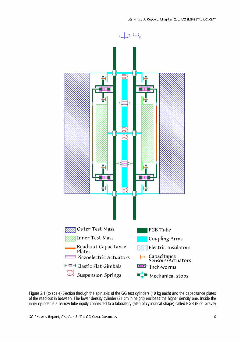
Figure 2.1 (to scale) Section through the spin axis of the GG test cylinders (10 kg each) and the capacitance platesof the read-out in between. The lower density cylinder (21 cm in height) encloses the higher density one. Inside theinner cylinder is a narrow tube rigidly connected to a laboratory (also of cylindrical shape) called PGB (Pico Gravity
**3KDVH$5HSRUW&KDSWHU(;3(5,0(17$/&21&(37
**3KDVH$5HSRUW&KDSWHU7+(**63$&((;3(5,0(17 17
Box) enclosing the test bodies and the read-out capacitance plates shown here. The PGB in its turn ismechanically suspended inside the spacecraft (not shown; see Fig. 2.8 for an overall view). For coupling the testbodies there are two “coupling” arms (shown in light blue) located inside the PGB tube but not in contact with it; theinner test cylinder is suspended from the coupling arms at its center by means of two helical springs; the outer oneis also suspended from the arms with helical springs, one at the top and one at the bottom of its symmetry axis. Theonly connection between the coupling arms and the PGB laboratory is via two flat gimbals at the midpoints of eacharm. Being pivoted on torsion wires the gimbals allow conical movements of the coupling arms around theirmidpoints, e.g. in response to a differential force between the test bodies. The piezoelectric actuators shown next tothe gimbals are for adjusting the length of the two halves of each coupling arm. The capacitance plates of theread−out are shown in between the test cylinders; they are connected to the PGB tube and have inch−worms foradjusting their distance from the surfaces of the test cylinders. On the PGB tube are shown the mechanical stopswhich constrain the test bodies to only slight movements. The small capacitance sensors/actuators (with plates ofabout 2 cm2) are for sensing and damping the slow whirl motions of the test bodies with respect to the PGB (seeSec. 2.1.5 and Chap. 6).
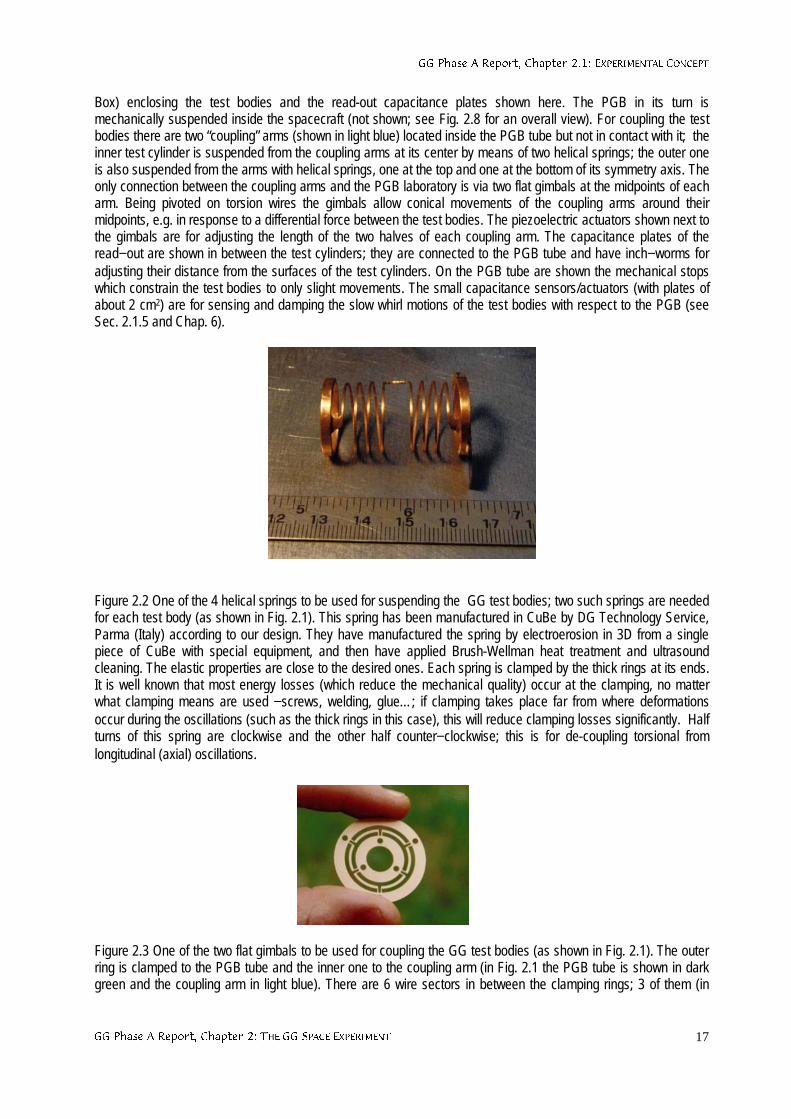
Figure 2.2 One of the 4 helical springs to be used for suspending the GG test bodies; two such springs are neededfor each test body (as shown in Fig. 2.1). This spring has been manufactured in CuBe by DG Technology Service,Parma (Italy) according to our design. They have manufactured the spring by electroerosion in 3D from a singlepiece of CuBe with special equipment, and then have applied Brush-Wellman heat treatment and ultrasoundcleaning. The elastic properties are close to the desired ones. Each spring is clamped by the thick rings at its ends.It is well known that most energy losses (which reduce the mechanical quality) occur at the clamping, no matterwhat clamping means are used −screws, welding, glue…; if clamping takes place far from where deformationsoccur during the oscillations (such as the thick rings in this case), this will reduce clamping losses significantly. Halfturns of this spring are clockwise and the other half counter−clockwise; this is for de-coupling torsional fromlongitudinal (axial) oscillations.
Figure 2.3 One of the two flat gimbals to be used for coupling the GG test bodies (as shown in Fig. 2.1). The outerring is clamped to the PGB tube and the inner one to the coupling arm (in Fig. 2.1 the PGB tube is shown in darkgreen and the coupling arm in light blue). There are 6 wire sectors in between the clamping rings; 3 of them (in
**3KDVH$5HSRUW&KDSWHU(;3(5,0(17$/&21&(37
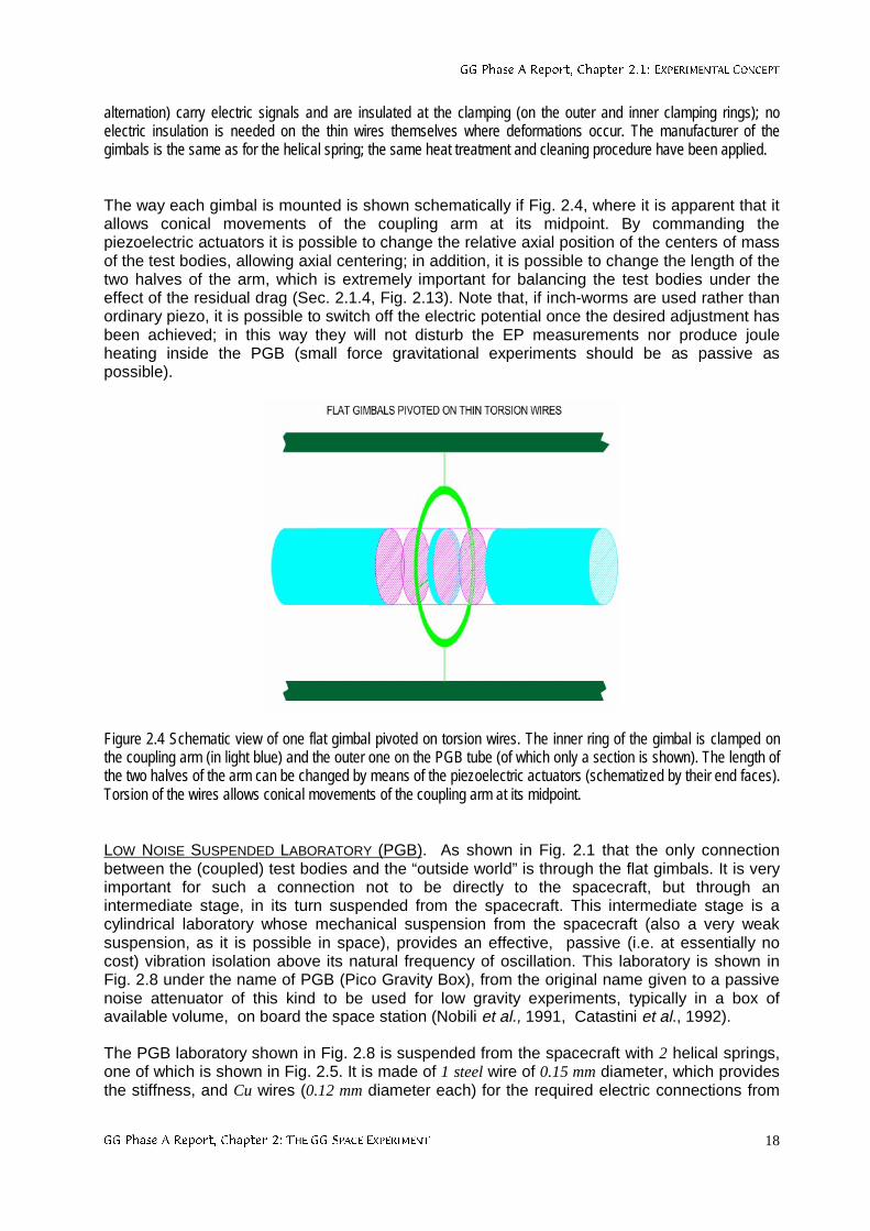
**3KDVH$5HSRUW&KDSWHU7+(**63$&((;3(5,0(17 18
alternation) carry electric signals and are insulated at the clamping (on the outer and inner clamping rings); noelectric insulation is needed on the thin wires themselves where deformations occur. The manufacturer of thegimbals is the same as for the helical spring; the same heat treatment and cleaning procedure have been applied.
The way each gimbal is mounted is shown schematically if Fig. 2.4, where it is apparent that itallows conical movements of the coupling arm at its midpoint. By commanding thepiezoelectric actuators it is possible to change the relative axial position of the centers of massof the test bodies, allowing axial centering; in addition, it is possible to change the length of thetwo halves of the arm, which is extremely important for balancing the test bodies under theeffect of the residual drag (Sec. 2.1.4, Fig. 2.13). Note that, if inch-worms are used rather thanordinary piezo, it is possible to switch off the electric potential once the desired adjustment hasbeen achieved; in this way they will not disturb the EP measurements nor produce jouleheating inside the PGB (small force gravitational experiments should be as passive aspossible).
Figure 2.4 Schematic view of one flat gimbal pivoted on torsion wires. The inner ring of the gimbal is clamped onthe coupling arm (in light blue) and the outer one on the PGB tube (of which only a section is shown). The length ofthe two halves of the arm can be changed by means of the piezoelectric actuators (schematized by their end faces).Torsion of the wires allows conical movements of the coupling arm at its midpoint.
LOW NOISE SUSPENDED LABORATORY (PGB). As shown in Fig. 2.1 that the only connectionbetween the (coupled) test bodies and the “outside world” is through the flat gimbals. It is veryimportant for such a connection not to be directly to the spacecraft, but through anintermediate stage, in its turn suspended from the spacecraft. This intermediate stage is acylindrical laboratory whose mechanical suspension from the spacecraft (also a very weaksuspension, as it is possible in space), provides an effective, passive (i.e. at essentially nocost) vibration isolation above its natural frequency of oscillation. This laboratory is shown inFig. 2.8 under the name of PGB (Pico Gravity Box), from the original name given to a passivenoise attenuator of this kind to be used for low gravity experiments, typically in a box ofavailable volume, on board the space station (Nobili et al., 1991, Catastini et al., 1992).
The PGB laboratory shown in Fig. 2.8 is suspended from the spacecraft with 2 helical springs,one of which is shown in Fig. 2.5. It is made of 1 steel wire of 0.15 mm diameter, which providesthe stiffness, and Cu wires (0.12 mm diameter each) for the required electric connections from
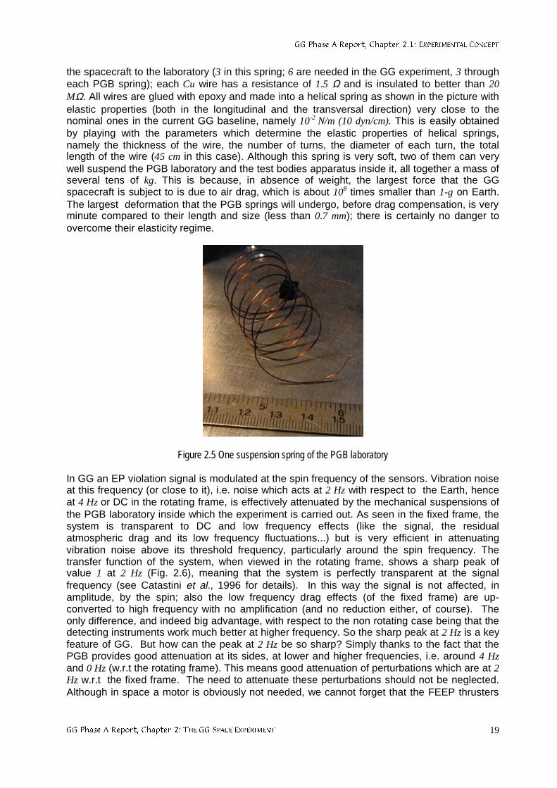
**3KDVH$5HSRUW&KDSWHU(;3(5,0(17$/&21&(37
**3KDVH$5HSRUW&KDSWHU7+(**63$&((;3(5,0(17 19
the spacecraft to the laboratory (3 in this spring; 6 are needed in the GG experiment, 3 througheach PGB spring); each Cu wire has a resistance of 1.5 Ω and is insulated to better than 20MΩ. All wires are glued with epoxy and made into a helical spring as shown in the picture withelastic properties (both in the longitudinal and the transversal direction) very close to thenominal ones in the current GG baseline, namely 10-2 N/m (10 dyn/cm). This is easily obtainedby playing with the parameters which determine the elastic properties of helical springs,namely the thickness of the wire, the number of turns, the diameter of each turn, the totallength of the wire (45 cm in this case). Although this spring is very soft, two of them can verywell suspend the PGB laboratory and the test bodies apparatus inside it, all together a mass ofseveral tens of kg. This is because, in absence of weight, the largest force that the GGspacecraft is subject to is due to air drag, which is about 108 times smaller than 1-g on Earth.The largest deformation that the PGB springs will undergo, before drag compensation, is veryminute compared to their length and size (less than 0.7 mm); there is certainly no danger toovercome their elasticity regime.
Figure 2.5 One suspension spring of the PGB laboratory
In GG an EP violation signal is modulated at the spin frequency of the sensors. Vibration noiseat this frequency (or close to it), i.e. noise which acts at 2 Hz with respect to the Earth, henceat 4 Hz or DC in the rotating frame, is effectively attenuated by the mechanical suspensions ofthe PGB laboratory inside which the experiment is carried out. As seen in the fixed frame, thesystem is transparent to DC and low frequency effects (like the signal, the residualatmospheric drag and its low frequency fluctuations...) but is very efficient in attenuatingvibration noise above its threshold frequency, particularly around the spin frequency. Thetransfer function of the system, when viewed in the rotating frame, shows a sharp peak ofvalue 1 at 2 Hz (Fig. 2.6), meaning that the system is perfectly transparent at the signalfrequency (see Catastini et al., 1996 for details). In this way the signal is not affected, inamplitude, by the spin; also the low frequency drag effects (of the fixed frame) are up-converted to high frequency with no amplification (and no reduction either, of course). Theonly difference, and indeed big advantage, with respect to the non rotating case being that thedetecting instruments work much better at higher frequency. So the sharp peak at 2 Hz is a keyfeature of GG. But how can the peak at 2 Hz be so sharp? Simply thanks to the fact that thePGB provides good attenuation at its sides, at lower and higher frequencies, i.e. around 4 Hzand 0 Hz (w.r.t the rotating frame). This means good attenuation of perturbations which are at 2Hz w.r.t the fixed frame. The need to attenuate these perturbations should not be neglected.Although in space a motor is obviously not needed, we cannot forget that the FEEP thrusters
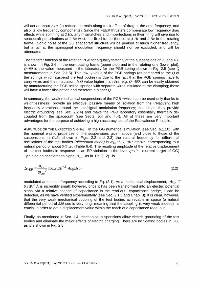
**3KDVH$5HSRUW&KDSWHU(;3(5,0(17$/&21&(37
**3KDVH$5HSRUW&KDSWHU7+(**63$&((;3(5,0(17 20
will act at about 2 Hz (to reduce the main along track effect of drag at the orbit frequency, andalso its low frequency components). Since the FEEP thrusters compensate low frequency drageffects while spinning at 2 Hz, any mismatches and imperfections in their firing will give rise tospacecraft perturbations at 2 Hz w.r.t. the fixed frame (hence at 4 Hz and 0 Hz in the rotatingframe). Sonic noise of the GG spacecraft structure will be peaked at much higher frequency,but a tail at the spin/signal modulation frequency should not be excluded, and will beattenuated.
The transfer function of the rotating PGB for a quality factor Q of the suspensions of 90 and 400is shown in Fig. 2.6, in the non-rotating frame (upper plot) and in the rotating one (lower plot).Q=90 is the value measured in the laboratory for the PGB spring shown in Fig. 2.5 (see Qmeasurements in Sec. 2.1.5). This low Q value of the PGB springs (as compared to the Q ofthe springs which suspend the test bodies) is due to the fact that the PGB springs have tocarry wires and their insulation. A Q value higher than this, e.g. Q=400, can be easily obtainedby manufacturing the PGB helical springs with separate wires insulated at the clamping; thesewill have a lower dissipation and therefore a higher Q.
In summary, the weak mechanical suspensions of the PGB −which can be used only thanks toweightlessness− provide an effective, passive means of isolation from the (relatively) highfrequency vibrations around the spin/signal modulation frequency; in addition, they provideelectric grounding (see Sec. 2.2.4) and make the PGB laboratory essentially thermally de-coupled from the spacecraft (see Sects. 5.4 and 4.4). All of these are very importantadvantages for the purpose of achieving a high accuracy test of the Equivalence Principle.
AMPLITUDE OF THE EXPECTED SIGNAL. In the GG numerical simulation (see Sec. 6.1.10), withthe nominal elastic properties of the suspensions given above (and close to those of thesuspensions in CuBe shown in Figs. 2.2 and 2.3) the natural frequency for differentialoscillations of the test bodies (differential mode) is ωdm ≅ 1.15⋅10-2 rad/sec, corresponding to anatural period of about 545 sec (Table 6.4). The resulting amplitude of the relative displacementof the test bodies in response to an EP violation to the level η=10-17 (current target of GG)−yielding an acceleration signal EPa as in Eq. (1.2)− is
Angstrom103.6a
x 32
dm
EPEP
−⋅≅ω
=∆ (2.2)
modulated at the spin frequency according to Eq. (2.1). As a mechanical displacement, ∆xEP ≅6.3⋅10-3 Å is incredibly small; however, once it has been transformed into an electric potentialsignal via a relative change of capacitance in the read-out capacitance bridge, it can bedetected, as we have verified experimentally (see Sec. 2.1.3 and Chap. 3). It is clear, however,that the very weak mechanical coupling of the test bodies achievable in space (a naturaldifferential period of 520 sec is very long, meaning that the coupling is very weak indeed) iscrucial in order to get a displacement value within the reach of a capacitance read−out.
Finally, as mentioned in Sec. 1.4, mechanical suspensions allow electric grounding of the testbodies and eliminate the major effects of electric charging. There are no floating bodies in GG,as it is shown in Fig. 2.8.
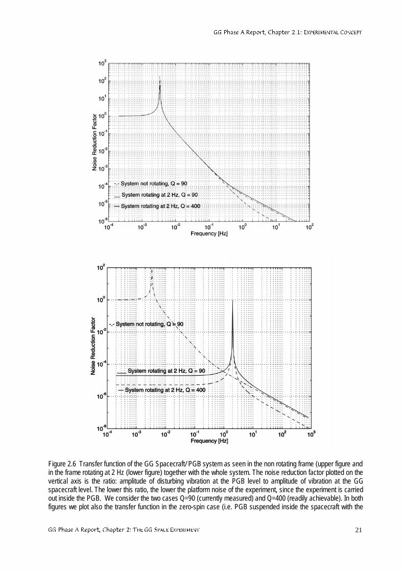
**3KDVH$5HSRUW&KDSWHU(;3(5,0(17$/&21&(37
**3KDVH$5HSRUW&KDSWHU7+(**63$&((;3(5,0(17 21
Figure 2.6 Transfer function of the GG Spacecraft/ PGB system as seen in the non rotating frame (upper figure andin the frame rotating at 2 Hz (lower figure) together with the whole system. The noise reduction factor plotted on thevertical axis is the ratio: amplitude of disturbing vibration at the PGB level to amplitude of vibration at the GGspacecraft level. The lower this ratio, the lower the platform noise of the experiment, since the experiment is carriedout inside the PGB. We consider the two cases Q=90 (currently measured) and Q=400 (readily achievable). In bothfigures we plot also the transfer function in the zero-spin case (i.e. PGB suspended inside the spacecraft with the
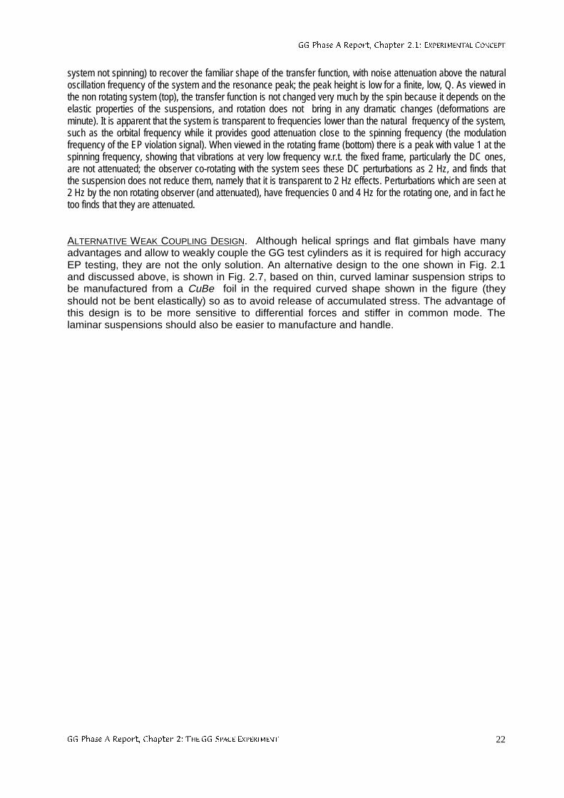
**3KDVH$5HSRUW&KDSWHU(;3(5,0(17$/&21&(37
**3KDVH$5HSRUW&KDSWHU7+(**63$&((;3(5,0(17 22
system not spinning) to recover the familiar shape of the transfer function, with noise attenuation above the naturaloscillation frequency of the system and the resonance peak; the peak height is low for a finite, low, Q. As viewed inthe non rotating system (top), the transfer function is not changed very much by the spin because it depends on theelastic properties of the suspensions, and rotation does not bring in any dramatic changes (deformations areminute). It is apparent that the system is transparent to frequencies lower than the natural frequency of the system,such as the orbital frequency while it provides good attenuation close to the spinning frequency (the modulationfrequency of the EP violation signal). When viewed in the rotating frame (bottom) there is a peak with value 1 at thespinning frequency, showing that vibrations at very low frequency w.r.t. the fixed frame, particularly the DC ones,are not attenuated; the observer co-rotating with the system sees these DC perturbations as 2 Hz, and finds thatthe suspension does not reduce them, namely that it is transparent to 2 Hz effects. Perturbations which are seen at2 Hz by the non rotating observer (and attenuated), have frequencies 0 and 4 Hz for the rotating one, and in fact hetoo finds that they are attenuated.
ALTERNATIVE WEAK COUPLING DESIGN. Although helical springs and flat gimbals have manyadvantages and allow to weakly couple the GG test cylinders as it is required for high accuracyEP testing, they are not the only solution. An alternative design to the one shown in Fig. 2.1and discussed above, is shown in Fig. 2.7, based on thin, curved laminar suspension strips tobe manufactured from a CuBe foil in the required curved shape shown in the figure (theyshould not be bent elastically) so as to avoid release of accumulated stress. The advantage ofthis design is to be more sensitive to differential forces and stiffer in common mode. Thelaminar suspensions should also be easier to manufacture and handle.
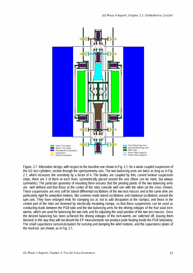
**3KDVH$5HSRUW&KDSWHU(;3(5,0(17$/&21&(37
**3KDVH$5HSRUW&KDSWHU7+(**63$&((;3(5,0(17 23
Figure. 2.7 Alternative design, with respect to the baseline one shown in Fig. 2.1, for a weak coupled suspension ofthe GG test cylinders; section through the spin/symmetry axis. The two balancing arms are twice as long as in Fig.2.1, which increases the sensitivity by a factor of 4. The bodies are coupled by thin, curved laminar suspensionstrips; there are 3 of them at each level, symmetrically placed around the axis (there can be more, but alwayssymmetric). The particular geometry of mounting them ensures that the pivoting points of the two balancing armsare well defined and that those at the center of the rotor coincide well one with the other (at the cross shown).These suspensions are very soft for lateral differential oscillations of the two test masses and at the same time areparticularly rigid for unwanted motions, like common mode lateral oscillations and rotational oscillations around thespin axis. They have enlarged ends for clamping (so as not to add dissipation at the clamps), and those in thecentral part of the rotor are fastened by electrically insulating clamps, so that these suspensions can be used asconducting leads between the PGB tube and the two balancing arms for the driving voltages of the four axial inch-worms, which are used for balancing the two rods and for adjusting the axial position of the two test masses. Oncethe desired balancing has been achieved the driving voltages of the inch-worms are switched off, leaving themblocked; in this way they will not disturb the EP measurements nor produce joule heating inside the PGB laboratory.The small capacitance sensors/actuators for sensing and damping the whirl motions, and the capacitance plates ofthe read-out are shown, as in Fig. 2.1.
**3KDVH$5HSRUW&KDSWHU(;3(5,0(17$/&21&(37
**3KDVH$5HSRUW&KDSWHU7+(**63$&((;3(5,0(17 24
2.1.2 IMPLICATIONS ON SPACECRAFT, ATTITUDE AND ORBIT
NEED FOR A SPIN STABILIZED SPACECRAFT IN LOW EARTH ORBIT. The test bodies, theirmechanical coupling and the capacitance read-out are the core of the GG mission. Once theexperimental design outlined in the previous section has been conceived, the features of therequired spacecraft, its attitude and orbit are also identified. In the first place, the cylindricalsymmetry of test bodies and PGB and the request to spin, suggest a spacecraft of cylindricalsymmetry too, stabilized by one-axis rotation along the symmetry axis. The nature of the signal(see Fig. 1.1 and Eq. 2.1) requires the spin axis to be as close as possible to the orbit normal;the need to reduce non gravitational perturbations on the spacecraft surface (Sec. 2.2.1)suggest that it should be small and compact (which in addition helps reducing its cost); theneed to reduce perturbations on the test bodies from nearby moving masses suggests to usethrusters of high specific impulse (such as FEEP; see Sec. 4.2) in order to reduce the amountof propellant required for drag compensation during the mission.
A section of the GG satellite through its spin/symmetry axis showing how the PGB and theexperimental apparatus is accommodated, in a nested arrangement inside it, is shown in Fig.2.8; a 3-D view is given in Fig. 2.9 (see Chap. 5 for details). The spacecraft is 1 m wide and 1.3m high. The area of the external (cylindrical) surfaces covered by solar cells is dictated by thepower needs of the mission (somewhat more than 100 W); the compactness of the spacecraft(similar to a spinning top in shape) is for maximizing the moment of inertia with respect to thesymmetry axis whereby providing passive spin stabilization around it. The current nominal spinrate is 2 Hz (120 rpm), yielding a peripheral acceleration of about 8 g, which is well doable.From the viewpoint of the EP experiment the modulation frequency of the signal, hence thefrequency of spin, should be as high as possible: the higher the better, to reduce mechanicalnoise and low frequency “1/f” electric noise. In addition, a higher spin rate, with very weaksuspensions at it is possible to use in space, makes the test bodies closer to being free, idealrotors (see Sec. 2.1.5), which is advantageous for the EP experiment. However, there arepractical constraints which is better not to push to their limits in order to reduce the complexityand cost of the spacecraft. A spin frequency of 5 Hz, with spacecraft dimensions close to thecurrent ones, was the original choice for GG (Nobili et al., 1993; Nobili et al., 1995). Thecurrent baseline is safer and poses no problems. Indeed, the first Italian satellite, SIRIO, flownmore than 20 years ago, was very similar to GG: cylindrical in shape, passively stabilized byone axis rotation, with mass, spin rate and maximum peripheral acceleration very close tothose of GG. In any case, a spin frequency of 2 Hz already provides a modulation of theexpected EP signal about 104 times higher than ever achieved.
From Eq. (1.2), which gives the intensity of the expected signal acceleration for an EP violationexpressed by the adimensional Eötvös parameter η, it is apparent that the lower is the orbitingaltitude the stronger is the signal. The altitude h of the satellite orbit is chosen having in mindtwo competing needs. On one side there is the need for an orbit altitude as low as possible, asthis increases the strength of the signal; however Eq. (1.2) shows that the dependence on h ofthe acceleration signal is very slow for low Earth satellites (R⊕>>h). On the other hand, thealtitude should be high in order to reduce the relevant disturbing effect from the residualatmosphere, at least as long as this becomes comparable to the effect of solar radiationpressure, which cannot be avoided anyway. The value of h is much more relevant for air dragacceleration than it is for the strength of the signal, because of its linear dependence on airdensity. In the current baseline we have h ≅ 520 km. It is worth noticing that in the case of GGthe only concern about a higher altitude is for a slightly weaker signal; there is no specialconcern on charged particle effects (as it is the case in STEP) because there are no relevantelectrostatic effects (Sec. 2.2.4).
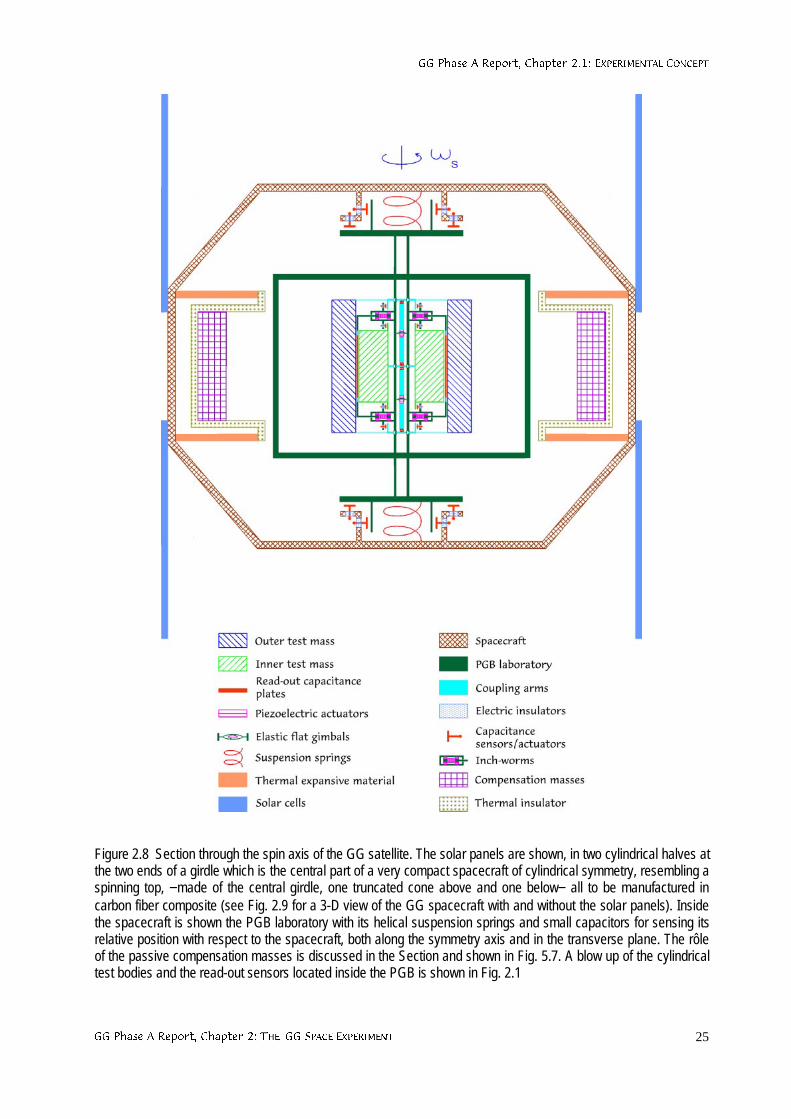
**3KDVH$5HSRUW&KDSWHU(;3(5,0(17$/&21&(37
**3KDVH$5HSRUW&KDSWHU7+(**63$&((;3(5,0(17 25
Figure 2.8 Section through the spin axis of the GG satellite. The solar panels are shown, in two cylindrical halves atthe two ends of a girdle which is the central part of a very compact spacecraft of cylindrical symmetry, resembling aspinning top, −made of the central girdle, one truncated cone above and one below− all to be manufactured incarbon fiber composite (see Fig. 2.9 for a 3-D view of the GG spacecraft with and without the solar panels). Insidethe spacecraft is shown the PGB laboratory with its helical suspension springs and small capacitors for sensing itsrelative position with respect to the spacecraft, both along the symmetry axis and in the transverse plane. The rôleof the passive compensation masses is discussed in the Section and shown in Fig. 5.7. A blow up of the cylindricaltest bodies and the read-out sensors located inside the PGB is shown in Fig. 2.1
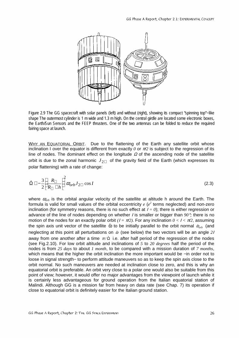
**3KDVH$5HSRUW&KDSWHU(;3(5,0(17$/&21&(37
**3KDVH$5HSRUW&KDSWHU7+(**63$&((;3(5,0(17 26
Figure 2.9 The GG spacecraft with solar panels (left) and without (right), showing its compact “spinning top”−likeshape The outermost cylinder is 1 m wide and 1.3 m high. On the central girdle are located some electronic boxes,the Earth/Sun Sensors and the FEEP thrusters. One of the two antennas can be folded to reduce the requiredfairing space at launch.
WHY AN EQUATORIAL ORBIT. Due to the flattening of the Earth any satellite orbit whoseinclination Ι over the equator is different from exactly 0 or π/2 is subject to the regression of itsline of nodes. The dominant effect on the longitude Ω of the ascending node of the satelliteorbit is due to the zonal harmonic ⊕2J of the gravity field of the Earth (which expresses its
polar flattening) with a rate of change:
IJhR
Rorb cos
2
32
2
⊕⊕
⊕
+
−≅Ω ω& (2.3)
where ωorb is the orbital angular velocity of the satellite at altitude h around the Earth. Theformula is valid for small values of the orbital eccentricity e (e2 terms neglected) and non-zeroinclination (for symmetry reasons, there is no such effect at Ι = 0); there is either regression oradvance of the line of nodes depending on whether Ι is smaller or bigger than 90°; there is nomotion of the nodes for an exactly polar orbit (Ι = π/2). For any inclination 0 < Ι < π/2, assumingthe spin axis unit vector of the satellite ω to be initially parallel to the orbit normal orbω (and
neglecting at this point all perturbations on ω (see below) the two vectors will be an angle 2Ιaway from one another after a time Ω&/π i.e. after half period of the regression of the nodes(see Fig.2.10). For low orbit altitude and inclinations of 5 to 20 degrees half the period of thenodes is from 25 days to about 1 month, to be compared with a mission duration of 7 months,which means that the higher the orbit inclination the more important would be −in order not toloose in signal strength− to perform attitude maneuvers so as to keep the spin axis close to theorbit normal. No such maneuvers are needed at inclination close to zero, and this is why anequatorial orbit is preferable. An orbit very close to a polar one would also be suitable from thispoint of view; however, it would offer no major advantages from the viewpoint of launch while itis certainly less advantageous for ground operation from the Italian equatorial station ofMalindi. Although GG is a mission far from heavy on data rate (see Chap. 7) its operation ifclose to equatorial orbit is definitely easier for the Italian ground station.
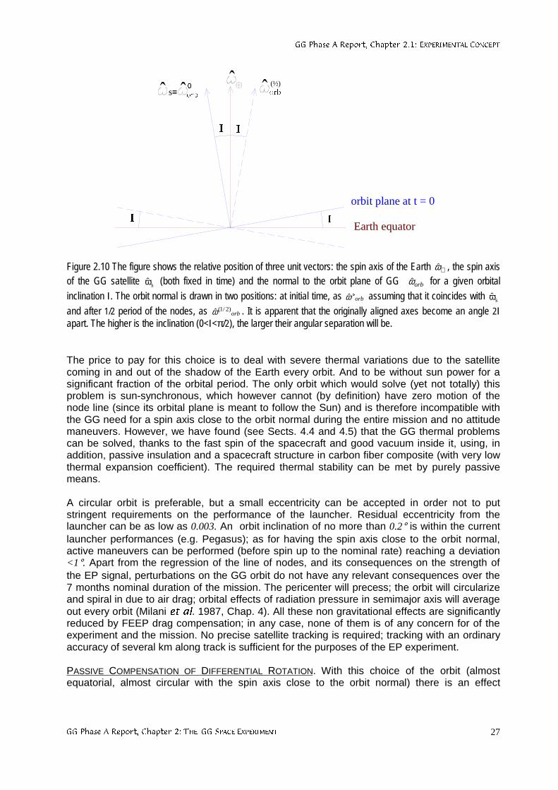
**3KDVH$5HSRUW&KDSWHU(;3(5,0(17$/&21&(37
**3KDVH$5HSRUW&KDSWHU7+(**63$&((;3(5,0(17 27
,,
RUE!! (½)
,,
!s≡ RUE!
orbit plane at t = 0
Earth equator
Figure 2.10 The figure shows the relative position of three unit vectors: the spin axis of the Earth ⊕ω , the spin axisof the GG satellite sω (both fixed in time) and the normal to the orbit plane of GG orbω for a given orbital
inclination Ι. The orbit normal is drawn in two positions: at initial time, as orboω assuming that it coincides with sω
and after 1/2 period of the nodes, as orb)2/1(ω . It is apparent that the originally aligned axes become an angle 2Ι
apart. The higher is the inclination (0<Ι<π/2), the larger their angular separation will be.
The price to pay for this choice is to deal with severe thermal variations due to the satellitecoming in and out of the shadow of the Earth every orbit. And to be without sun power for asignificant fraction of the orbital period. The only orbit which would solve (yet not totally) thisproblem is sun-synchronous, which however cannot (by definition) have zero motion of thenode line (since its orbital plane is meant to follow the Sun) and is therefore incompatible withthe GG need for a spin axis close to the orbit normal during the entire mission and no attitudemaneuvers. However, we have found (see Sects. 4.4 and 4.5) that the GG thermal problemscan be solved, thanks to the fast spin of the spacecraft and good vacuum inside it, using, inaddition, passive insulation and a spacecraft structure in carbon fiber composite (with very lowthermal expansion coefficient). The required thermal stability can be met by purely passivemeans.
A circular orbit is preferable, but a small eccentricity can be accepted in order not to putstringent requirements on the performance of the launcher. Residual eccentricity from thelauncher can be as low as 0.003. An orbit inclination of no more than 0.2° is within the currentlauncher performances (e.g. Pegasus); as for having the spin axis close to the orbit normal,active maneuvers can be performed (before spin up to the nominal rate) reaching a deviation<1°. Apart from the regression of the line of nodes, and its consequences on the strength ofthe EP signal, perturbations on the GG orbit do not have any relevant consequences over the7 months nominal duration of the mission. The pericenter will precess; the orbit will circularizeand spiral in due to air drag; orbital effects of radiation pressure in semimajor axis will averageout every orbit (Milani HWDO. 1987, Chap. 4). All these non gravitational effects are significantlyreduced by FEEP drag compensation; in any case, none of them is of any concern for of theexperiment and the mission. No precise satellite tracking is required; tracking with an ordinaryaccuracy of several km along track is sufficient for the purposes of the EP experiment.
PASSIVE COMPENSATION OF DIFFERENTIAL ROTATION. With this choice of the orbit (almostequatorial, almost circular with the spin axis close to the orbit normal) there is an effect
**3KDVH$5HSRUW&KDSWHU(;3(5,0(17$/&21&(37
**3KDVH$5HSRUW&KDSWHU7+(**63$&((;3(5,0(17 28
induced by eclipses which gives rise to an angular phase lag between the spacecraft outershell and the payload suspended inside it, and it must therefore be taken care of (Lund, 1995).
The spin rate ωos of the outer shell will change if the moment of inertia of the shell changeswhile the spin angular momentum remains constant. This indeed happens every orbit due totemperature variations of the outer shell as the GG satellite gets in and out of the Earthshadow, which is not the case for the PGB laboratory since it is very well insulated andthermally de-coupled from the spacecraft (see Sects. 4.4 and 5.4). Hence, a differentialrotation rate of the outer shell with respect to the PGB is to be expected. The relative changeof the angular velocity of the outer shell ωos with respect to its nominal spin angular velocity ωs
must equal the relative change of its moment of inertia Jz with respect to the symmetry/spinaxis (due to the conservation of spin angular momentum), and it must be:
T2J
Jos
z
z
s
os ∆⋅α≅∆=ωω∆
(2.4)
where αos is the thermal expansion coefficient of the outer shell and ∆T its temperaturevariation due to the eclipse. Because of the low torsion constant of the PGB springs the naturalperiod for torsion oscillations of the spacecraft/PGB systems is longer than the eclipse duration(about 1/3 of the orbit period); as a consequence, a differential rotation rate will accumulateover the eclipse passage, yielding a corresponding phase lag between the two bodies. Weshall have:
eclipsesoseclipseos T τωαω ⋅∆⋅⋅≅∆ 2)( (2.5)
for the variation of the spin angular velocity in 1 eclipse passage of duration τeclipse, and acorresponding phase lag:
eclipsesoseclipse T τωα ⋅∆⋅⋅≅Θ (2.6)
The GG thermal model gives ∆T ≅ 30 degrees for the temperature variation of the spacecraft in 1eclipse passage; if the spacecraft is made of carbon fiber composite it is reasonable to have athermal expansion coefficient αos ≅ 0.9⋅10-6/K; thus:
rad8.0eclipse ≅Θ (2.7)
This result has been confirmed by detailed theoretical and numerical analysis; it is clearlyunacceptable and calls for a solution. A way to solving it comes from noticing that such a largephase lag is due to the high spin rate of the spacecraft (together with the fact that the phasedifference grows quadratically in time) while the absolute change in the moment of inertia isindeed very small. This means that it can be balanced by a small compensation mass.Moreover, compensation can be passive (Marchal, 1996); the idea is to have a mass whichexpands and contracts in anti-phase with respect to the outer shell of the spacecraft so as tokeep the total moment of inertia (of the outer shell plus the compensation mass) essentiallyconstant. Since the compensation mass should be small compared to the mass of the outershell, clearly its expansion coefficient must be larger than the expansion coefficient of the outershell (if the masses have about the same distance from the spin axis). Expansion is requiredin the radial direction (normal to the spin axis) because this is how the outer shell expands andcontracts. Hence, there must be bars located radially from the cylindrical surface towards thespin axis, while the bulk of the compensation mass should be as close as possible to the outershell in order to give the highest contribution to the total moment of inertia (and thus to its
**3KDVH$5HSRUW&KDSWHU(;3(5,0(17$/&21&(37
**3KDVH$5HSRUW&KDSWHU7+(**63$&((;3(5,0(17 29
variations as well). Also, materials with high expansion coefficients tend to have low density.From all this we are led to the design shown in Fig. 2.8: a number of bar shaped supports withlarge thermal expansion coefficient αbar are located radially from the outer shell surface (inthermal contact with it) towards the spin axis; from the other ends, getting back towards thesurface of the spacecraft, there are thermal insulating low expansion bars at whose ends thecompensation masses are attached. As the spacecraft outer shell expands outward thecompensation masses are displaced inward, and viceversa. The compensation masses arefar away from the spin axis thus giving a large contribution to the moment of inertia. Careshould be taken in maintaining symmetry in azimuth as well as top/down. Also, thermalinsulation of the top radial bars and insulating masses is necessary not to bring heat inside.Three possible mass compensation designs are shown in Fig. 5.7. For the total moment ofinertia to remain constant the ratio of the thermal expansion coefficients and the ratio of themoments of inertia (with respect to the spin axis) must satisfy the equation:
cm
os
os
bar
J
J=αα
(2.8)
and, with the design outlined above:
bar
cm
cmbar
os
os
cm
l
r
r
r
m
m ⋅
⋅=
2
αα
(2.9)
with mcm the total compensation mass (with bars of negligible mass), mos and r the mass andradius of the outer shell, rcm the radial distance of the compensation mass from the spin axis,lbar the length of the high thermal expansion bar. Using materials with αbar a factor 50 to 100times larger than the expansion coefficient of the outer shell in carbon fiber it is found that acompensation mass not larger than 5 kg is sufficient. Note that a small compensation mass,and a small mass for the bar, i.e. a small mass for the entire system means that heat can betransferred (hence expansion/contraction achieved to compensate for those of the spacecraft)in a very short time.
How rapidly must this passive mass compensation system work in order to keep the phase lagbetween the outer shell and the PGB within a required phase difference rad01.0req ≅Θ(namely, 1/10 of the of angle available by the mechanical stops)? Assuming the temperaturechange to be linear in time we get a quadratic growth of the phase lag angle with acceleration:
27sos rad/sec104.3T2 ⋅≅ωα≅Θ −&&& (2.10)
giving about 240 sec for the response of the compensation system. Materials with thermalexpansion coefficient as large as 10-4/K to be used for manufacturing the bars tend to havelow thermal conductivity; they can have a thermally conductive inner bar so as to increase thesurface of thermal contact with the expanding/contracting outer shell of the spacecraft thusreducing the response time. In any case there is sufficient time available. Instead, it is possibleto use bars is special Al alloy which have somewhat smaller thermal expansion coefficient buthigh thermal conductivity and need no inner bar. The gravitational perturbation on the testbodies of all the moving mass (from the outer shell as well as the compensation mass) hasbeen estimated and found not to be a problem (Sec. 2.2.5).
In the conservative assumption that 10% of (2.10) is not compensated passively, for theresidual angular acceleration between the spacecraft and the PGB (3.4⋅10-8 rad/sec2) the
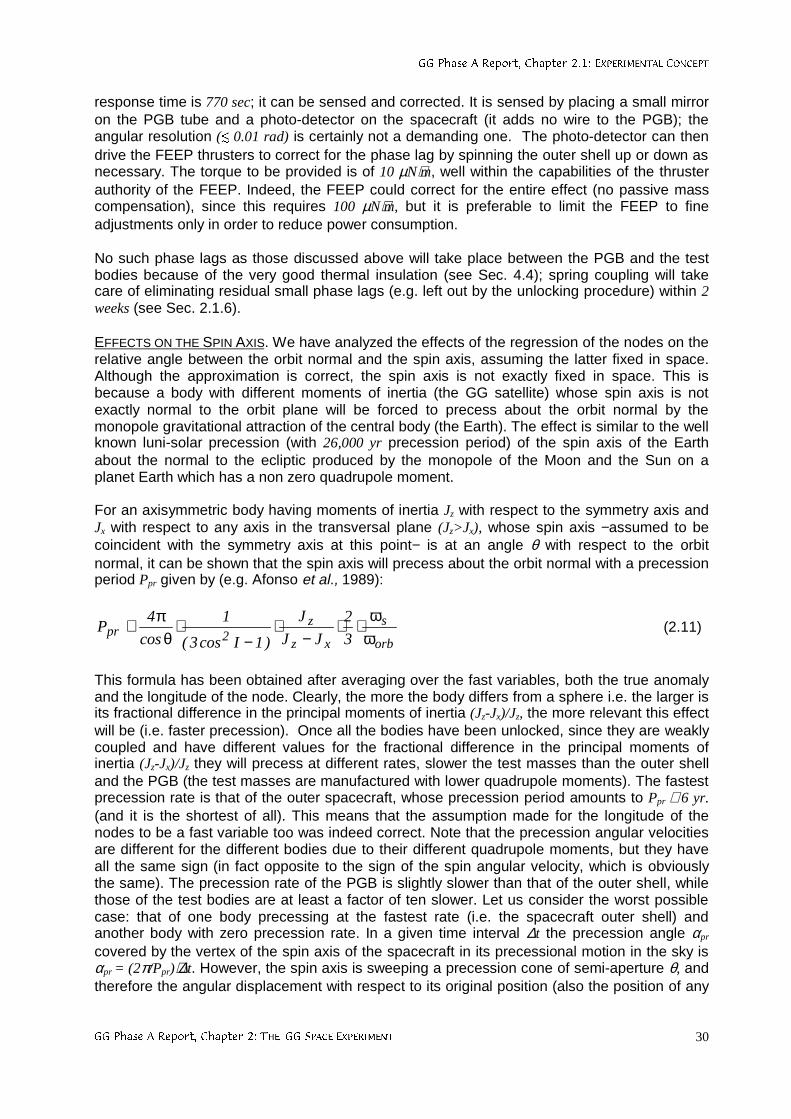
**3KDVH$5HSRUW&KDSWHU(;3(5,0(17$/&21&(37
**3KDVH$5HSRUW&KDSWHU7+(**63$&((;3(5,0(17 30
response time is 770 sec; it can be sensed and corrected. It is sensed by placing a small mirroron the PGB tube and a photo-detector on the spacecraft (it adds no wire to the PGB); theangular resolution (¨ 0.01 rad) is certainly not a demanding one. The photo-detector can thendrive the FEEP thrusters to correct for the phase lag by spinning the outer shell up or down asnecessary. The torque to be provided is of 10 µN⋅m, well within the capabilities of the thrusterauthority of the FEEP. Indeed, the FEEP could correct for the entire effect (no passive masscompensation), since this requires 100 µN⋅m, but it is preferable to limit the FEEP to fineadjustments only in order to reduce power consumption.
No such phase lags as those discussed above will take place between the PGB and the testbodies because of the very good thermal insulation (see Sec. 4.4); spring coupling will takecare of eliminating residual small phase lags (e.g. left out by the unlocking procedure) within 2weeks (see Sec. 2.1.6).
EFFECTS ON THE SPIN AXIS. We have analyzed the effects of the regression of the nodes on therelative angle between the orbit normal and the spin axis, assuming the latter fixed in space.Although the approximation is correct, the spin axis is not exactly fixed in space. This isbecause a body with different moments of inertia (the GG satellite) whose spin axis is notexactly normal to the orbit plane will be forced to precess about the orbit normal by themonopole gravitational attraction of the central body (the Earth). The effect is similar to the wellknown luni-solar precession (with 26,000 yr precession period) of the spin axis of the Earthabout the normal to the ecliptic produced by the monopole of the Moon and the Sun on aplanet Earth which has a non zero quadrupole moment.
For an axisymmetric body having moments of inertia Jz with respect to the symmetry axis andJx with respect to any axis in the transversal plane (Jz>Jx), whose spin axis −assumed to becoincident with the symmetry axis at this point− is at an angle θ with respect to the orbitnormal, it can be shown that the spin axis will precess about the orbit normal with a precessionperiod Ppr given by (e.g. Afonso et al., 1989):
orb
s
xz
z2pr 3
2
JJ
J
)1Icos3(
1
cos
4P
ωω
⋅⋅−
⋅−
⋅θ
π≅ (2.11)
This formula has been obtained after averaging over the fast variables, both the true anomalyand the longitude of the node. Clearly, the more the body differs from a sphere i.e. the larger isits fractional difference in the principal moments of inertia (Jz-Jx)/Jz, the more relevant this effectwill be (i.e. faster precession). Once all the bodies have been unlocked, since they are weaklycoupled and have different values for the fractional difference in the principal moments ofinertia (Jz-Jx)/Jz they will precess at different rates, slower the test masses than the outer shelland the PGB (the test masses are manufactured with lower quadrupole moments). The fastestprecession rate is that of the outer spacecraft, whose precession period amounts to Ppr ≅ 6 yr.(and it is the shortest of all). This means that the assumption made for the longitude of thenodes to be a fast variable too was indeed correct. Note that the precession angular velocitiesare different for the different bodies due to their different quadrupole moments, but they haveall the same sign (in fact opposite to the sign of the spin angular velocity, which is obviouslythe same). The precession rate of the PGB is slightly slower than that of the outer shell, whilethose of the test bodies are at least a factor of ten slower. Let us consider the worst possiblecase: that of one body precessing at the fastest rate (i.e. the spacecraft outer shell) andanother body with zero precession rate. In a given time interval ∆t the precession angle αpr
covered by the vertex of the spin axis of the spacecraft in its precessional motion in the sky isαpr = (2π/Ppr)⋅∆t. However, the spin axis is sweeping a precession cone of semi-aperture θ, andtherefore the angular displacement with respect to its original position (also the position of any
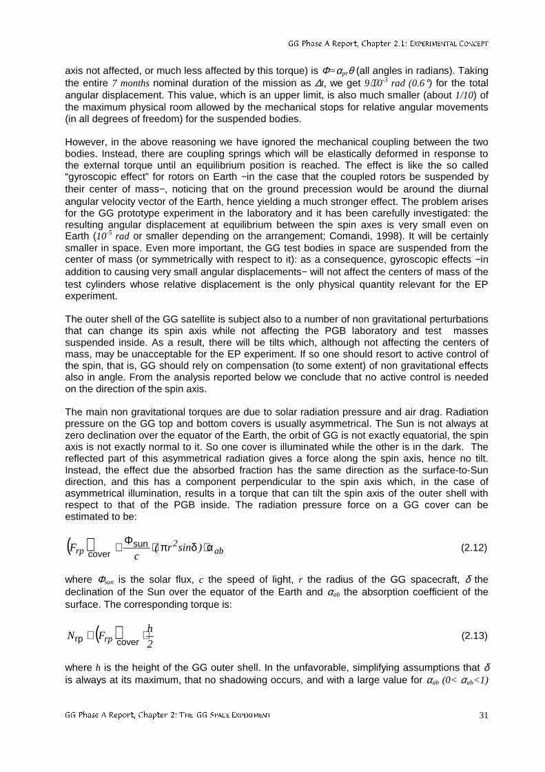
**3KDVH$5HSRUW&KDSWHU(;3(5,0(17$/&21&(37
**3KDVH$5HSRUW&KDSWHU7+(**63$&((;3(5,0(17 31
axis not affected, or much less affected by this torque) is Φ=αprθ (all angles in radians). Takingthe entire 7 months nominal duration of the mission as ∆t, we get 9⋅10-3 rad (0.6°) for the totalangular displacement. This value, which is an upper limit, is also much smaller (about 1/10) ofthe maximum physical room allowed by the mechanical stops for relative angular movements(in all degrees of freedom) for the suspended bodies.
However, in the above reasoning we have ignored the mechanical coupling between the twobodies. Instead, there are coupling springs which will be elastically deformed in response tothe external torque until an equilibrium position is reached. The effect is like the so called“gyroscopic effect” for rotors on Earth −in the case that the coupled rotors be suspended bytheir center of mass−, noticing that on the ground precession would be around the diurnalangular velocity vector of the Earth, hence yielding a much stronger effect. The problem arisesfor the GG prototype experiment in the laboratory and it has been carefully investigated: theresulting angular displacement at equilibrium between the spin axes is very small even onEarth (10-5 rad or smaller depending on the arrangement; Comandi, 1998). It will be certainlysmaller in space. Even more important, the GG test bodies in space are suspended from thecenter of mass (or symmetrically with respect to it): as a consequence, gyroscopic effects −inaddition to causing very small angular displacements− will not affect the centers of mass of thetest cylinders whose relative displacement is the only physical quantity relevant for the EPexperiment.
The outer shell of the GG satellite is subject also to a number of non gravitational perturbationsthat can change its spin axis while not affecting the PGB laboratory and test massessuspended inside. As a result, there will be tilts which, although not affecting the centers ofmass, may be unacceptable for the EP experiment. If so one should resort to active control ofthe spin, that is, GG should rely on compensation (to some extent) of non gravitational effectsalso in angle. From the analysis reported below we conclude that no active control is neededon the direction of the spin axis.
The main non gravitational torques are due to solar radiation pressure and air drag. Radiationpressure on the GG top and bottom covers is usually asymmetrical. The Sun is not always atzero declination over the equator of the Earth, the orbit of GG is not exactly equatorial, the spinaxis is not exactly normal to it. So one cover is illuminated while the other is in the dark. Thereflected part of this asymmetrical radiation gives a force along the spin axis, hence no tilt.Instead, the effect due the absorbed fraction has the same direction as the surface-to-Sundirection, and this has a component perpendicular to the spin axis which, in the case ofasymmetrical illumination, results in a torque that can tilt the spin axis of the outer shell withrespect to that of the PGB inside. The radiation pressure force on a GG cover can beestimated to be:
( ) ab2
rp )sinr(c
F α⋅δπ⋅Φ≅ suncover
(2.12)
where Φsun is the solar flux, c the speed of light, r the radius of the GG spacecraft, δ thedeclination of the Sun over the equator of the Earth and αab the absorption coefficient of thesurface. The corresponding torque is:
( )2
hFN rp ⋅≅
coverrp (2.13)
where h is the height of the GG outer shell. In the unfavorable, simplifying assumptions that δis always at its maximum, that no shadowing occurs, and with a large value for αab (0< αab<1)
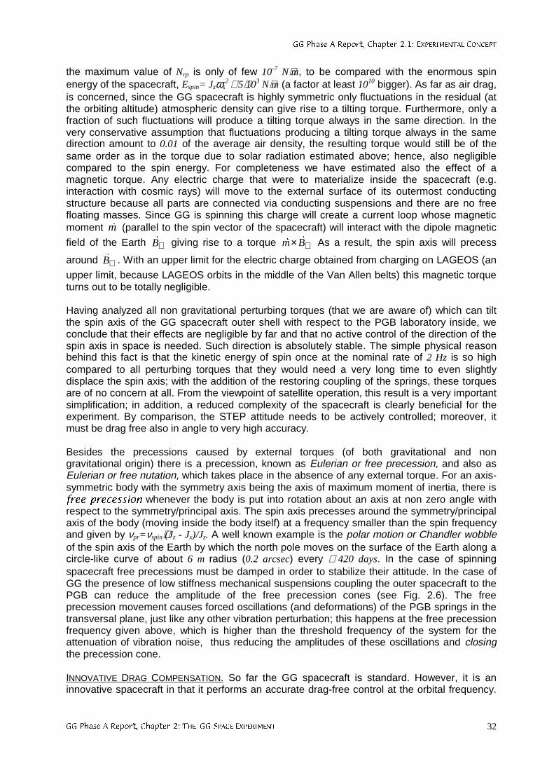
**3KDVH$5HSRUW&KDSWHU(;3(5,0(17$/&21&(37
**3KDVH$5HSRUW&KDSWHU7+(**63$&((;3(5,0(17 32
the maximum value of Nrp is only of few 10-7 N⋅m, to be compared with the enormous spinenergy of the spacecraft, Espin= Jzωs
2 ≅ 5⋅103 N⋅m (a factor at least 1010 bigger). As far as air drag,is concerned, since the GG spacecraft is highly symmetric only fluctuations in the residual (atthe orbiting altitude) atmospheric density can give rise to a tilting torque. Furthermore, only afraction of such fluctuations will produce a tilting torque always in the same direction. In thevery conservative assumption that fluctuations producing a tilting torque always in the samedirection amount to 0.01 of the average air density, the resulting torque would still be of thesame order as in the torque due to solar radiation estimated above; hence, also negligiblecompared to the spin energy. For completeness we have estimated also the effect of amagnetic torque. Any electric charge that were to materialize inside the spacecraft (e.g.interaction with cosmic rays) will move to the external surface of its outermost conductingstructure because all parts are connected via conducting suspensions and there are no freefloating masses. Since GG is spinning this charge will create a current loop whose magneticmoment m
r
(parallel to the spin vector of the spacecraft) will interact with the dipole magnetic
field of the Earth ⊕Br
giving rise to a torque ⊕× Bmr
r
As a result, the spin axis will precess
around ⊕Br
. With an upper limit for the electric charge obtained from charging on LAGEOS (an
upper limit, because LAGEOS orbits in the middle of the Van Allen belts) this magnetic torqueturns out to be totally negligible.
Having analyzed all non gravitational perturbing torques (that we are aware of) which can tiltthe spin axis of the GG spacecraft outer shell with respect to the PGB laboratory inside, weconclude that their effects are negligible by far and that no active control of the direction of thespin axis in space is needed. Such direction is absolutely stable. The simple physical reasonbehind this fact is that the kinetic energy of spin once at the nominal rate of 2 Hz is so highcompared to all perturbing torques that they would need a very long time to even slightlydisplace the spin axis; with the addition of the restoring coupling of the springs, these torquesare of no concern at all. From the viewpoint of satellite operation, this result is a very importantsimplification; in addition, a reduced complexity of the spacecraft is clearly beneficial for theexperiment. By comparison, the STEP attitude needs to be actively controlled; moreover, itmust be drag free also in angle to very high accuracy.
Besides the precessions caused by external torques (of both gravitational and nongravitational origin) there is a precession, known as Eulerian or free precession, and also asEulerian or free nutation, which takes place in the absence of any external torque. For an axis-symmetric body with the symmetry axis being the axis of maximum moment of inertia, there isIUHHSUHFHVVLRQ whenever the body is put into rotation about an axis at non zero angle withrespect to the symmetry/principal axis. The spin axis precesses around the symmetry/principalaxis of the body (moving inside the body itself) at a frequency smaller than the spin frequencyand given by νpr=νspin⋅(Jz - Jx)/Jz. A well known example is the polar motion or Chandlerwobbleof the spin axis of the Earth by which the north pole moves on the surface of the Earth along acircle-like curve of about 6 m radius (0.2 arcsec) every ≅ 420 days. In the case of spinningspacecraft free precessions must be damped in order to stabilize their attitude. In the case ofGG the presence of low stiffness mechanical suspensions coupling the outer spacecraft to thePGB can reduce the amplitude of the free precession cones (see Fig. 2.6). The freeprecession movement causes forced oscillations (and deformations) of the PGB springs in thetransversal plane, just like any other vibration perturbation; this happens at the free precessionfrequency given above, which is higher than the threshold frequency of the system for theattenuation of vibration noise, thus reducing the amplitudes of these oscillations and closingthe precession cone.
INNOVATIVE DRAG COMPENSATION. So far the GG spacecraft is standard. However, it is aninnovative spacecraft in that it performs an accurate drag-free control at the orbital frequency.
**3KDVH$5HSRUW&KDSWHU(;3(5,0(17$/&21&(37
**3KDVH$5HSRUW&KDSWHU7+(**63$&((;3(5,0(17 33
The request for drag compensation comes from the experiment, because the effect of air dragis by far larger −by many orders of magnitude; see Sec. 2.2.1− than the expected signal. Theresidual atmosphere at the satellite orbiting altitude (as well as radiation from the Sun, theEarth’s albedo and the infrared Earth radiation) act on the outer surface of the GG spacecraftbut not on the test bodies suspended inside. Since gyroscopic effects are negligible (becauseof the very high energy of spin the GG spinning bodies are essentially unaffected by tilts andtorques), these non-gravitational effects appear as inertial accelerations on the test bodies towhich they are transferred via the flat gimbals on the coupling arms (as shown in Fig. 2.1),ideally −i.e. in case of perfect balancing of the test bodies; see Sec. 2.1.4− equal and oppositeto the acceleration acquired by the spacecraft. Most of the effect (along-track) is at thesatellite orbiting frequency around the Earth; smaller, low frequency variations are also to beexpected. In the ideal case of perfect balancing of the test bodies air drag effects would causeno differential displacement of the bodies (with respect to one another), hence not competingwith the EP differential signal. In reality balancing is not perfect, and it is a good strategy thatthe burden of dealing with air drag effects be shared between the experiment core, by accuratebalancing of the test bodies, and the spacecraft itself −by making it drag-free, i.e. capable ofcompensating for air drag.
In GG drag compensation is performed with FEEP thrusters, whose advantages for highprecision missions in Fundamental Physics devoted to the detection of very small forces, arenumerous: high specific impulse, negligible amount of propellant (few grams for a few monthsmission duration), no moving parts, fine electric tuning and consequent high level ofproportionality. The motion of the PGB with respect to the spacecraft is monitored by smallcapacitance sensors (shown in Fig. 2.8) which drive the FEEP thrusters (spinning with thesystem) for compensation. The actual configuration of FEEP thrusters on GG for dragcompensation (6 in total) is given in Sec. 5.5 and Fig. 5.15. The drag-free control is based on anotch filter, and requires the thrusters to fire close to the spin frequency; it has been designedand implemented in a finite element numerical simulation of the full GG system (see Sec.6.15). The corresponding vibration noise (close to the signal modulation frequency) is veryeffectively reduced by the PGB suspensions according to the transfer function of Fig. 2.6, andtherefore does not reach the test bodies. The FEEP thrusters and their control electronics arediscussed in Sec. 4.2. The current GG requirements on drag compensation are given in Sec.2.1.1.
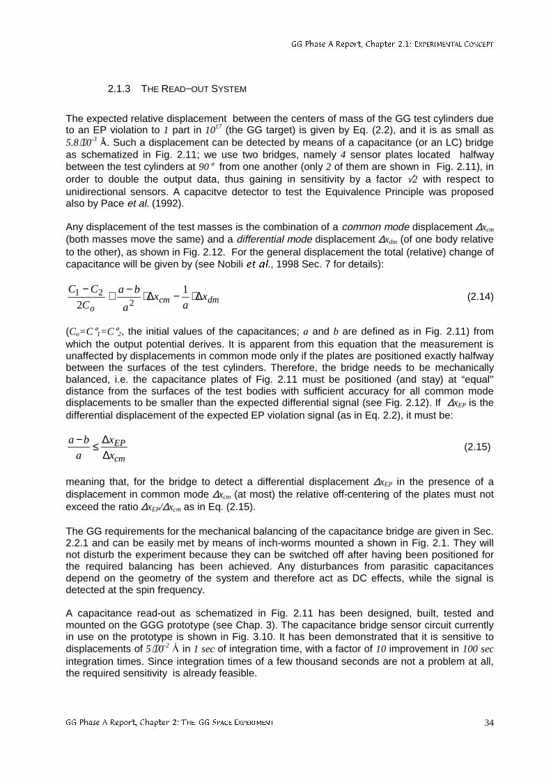
**3KDVH$5HSRUW&KDSWHU(;3(5,0(17$/&21&(37
**3KDVH$5HSRUW&KDSWHU7+(**63$&((;3(5,0(17 34
2.1.3 THE READ−OUT SYSTEM
The expected relative displacement between the centers of mass of the GG test cylinders dueto an EP violation to 1 part in 1017 (the GG target) is given by Eq. (2.2), and it is as small as5.8⋅10-3 . Such a displacement can be detected by means of a capacitance (or an LC) bridgeas schematized in Fig. 2.11; we use two bridges, namely 4 sensor plates located halfwaybetween the test cylinders at 90° from one another (only 2 of them are shown in Fig. 2.11), inorder to double the output data, thus gaining in sensitivity by a factor √2 with respect tounidirectional sensors. A capacitve detector to test the Equivalence Principle was proposedalso by Pace et al. (1992).
Any displacement of the test masses is the combination of a common mode displacement ∆xcm
(both masses move the same) and a differential mode displacement ∆xdm (of one body relativeto the other), as shown in Fig. 2.12. For the general displacement the total (relative) change ofcapacitance will be given by (see Nobili HWDO., 1998 Sec. 7 for details):
dmcmo
xa
xa
ba
C
CC∆⋅−∆⋅−≅
− 1
2 221 (2.14)
(Co=C°1=C°2, the initial values of the capacitances; a and b are defined as in Fig. 2.11) fromwhich the output potential derives. It is apparent from this equation that the measurement isunaffected by displacements in common mode only if the plates are positioned exactly halfwaybetween the surfaces of the test cylinders. Therefore, the bridge needs to be mechanicallybalanced, i.e. the capacitance plates of Fig. 2.11 must be positioned (and stay) at “equal''distance from the surfaces of the test bodies with sufficient accuracy for all common modedisplacements to be smaller than the expected differential signal (see Fig. 2.12). If ∆xEP is thedifferential displacement of the expected EP violation signal (as in Eq. 2.2), it must be:
cm
EP
x
x
a
ba
∆∆≤−
(2.15)
meaning that, for the bridge to detect a differential displacement ∆xEP in the presence of adisplacement in common mode ∆xcm (at most) the relative off-centering of the plates must notexceed the ratio ∆xEP/∆xcm as in Eq. (2.15).
The GG requirements for the mechanical balancing of the capacitance bridge are given in Sec.2.2.1 and can be easily met by means of inch-worms mounted a shown in Fig. 2.1. They willnot disturb the experiment because they can be switched off after having been positioned forthe required balancing has been achieved. Any disturbances from parasitic capacitancesdepend on the geometry of the system and therefore act as DC effects, while the signal isdetected at the spin frequency.
A capacitance read-out as schematized in Fig. 2.11 has been designed, built, tested andmounted on the GGG prototype (see Chap. 3). The capacitance bridge sensor circuit currentlyin use on the prototype is shown in Fig. 3.10. It has been demonstrated that it is sensitive todisplacements of 5⋅10-2 in 1 sec of integration time, with a factor of 10 improvement in 100 secintegration times. Since integration times of a few thousand seconds are not a problem at all,the required sensitivity is already feasible.
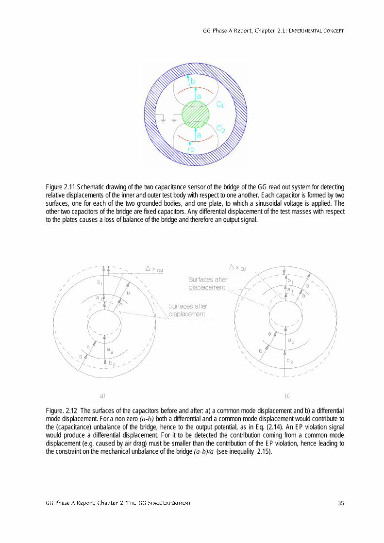
**3KDVH$5HSRUW&KDSWHU(;3(5,0(17$/&21&(37
**3KDVH$5HSRUW&KDSWHU7+(**63$&((;3(5,0(17 35
Figure 2.11 Schematic drawing of the two capacitance sensor of the bridge of the GG read out system for detectingrelative displacements of the inner and outer test body with respect to one another. Each capacitor is formed by twosurfaces, one for each of the two grounded bodies, and one plate, to which a sinusoidal voltage is applied. Theother two capacitors of the bridge are fixed capacitors. Any differential displacement of the test masses with respectto the plates causes a loss of balance of the bridge and therefore an output signal.
Figure. 2.12 The surfaces of the capacitors before and after: a) a common mode displacement and b) a differentialmode displacement. For a non zero (a-b) both a differential and a common mode displacement would contribute tothe (capacitance) unbalance of the bridge, hence to the output potential, as in Eq. (2.14). An EP violation signalwould produce a differential displacement. For it to be detected the contribution coming from a common modedisplacement (e.g. caused by air drag) must be smaller than the contribution of the EP violation, hence leading tothe constraint on the mechanical unbalance of the bridge (a-b)/a(see inequality 2.15).
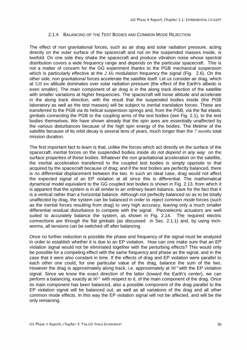
**3KDVH$5HSRUW&KDSWHU(;3(5,0(17$/&21&(37
**3KDVH$5HSRUW&KDSWHU7+(**63$&((;3(5,0(17 36
2.1.4 BALANCING OF THE TEST BODIES AND COMMON MODE REJECTION
The effect of non gravitational forces, such as air drag and solar radiation pressure, actingdirectly on the outer surface of the spacecraft and not on the suspended masses inside, istwofold. On one side they shake the spacecraft and produce vibration noise whose spectraldistribution covers a wide frequency range and depends on the particular spacecraft. This isnot a matter of concern for the GG experiment thanks to the PGB mechanical suspensionwhich is particularly effective at the 2 Hz modulation frequency the signal (Fig. 2.6). On theother side, non gravitational forces accelerate the satellite itself. Let us consider air drag, whichat 520 km altitude dominates over solar radiation pressure (the effect of the Earth’s albedo iseven smaller). The main component of air drag is in the along track direction of the satellitewith smaller variations at higher frequencies. The spacecraft will loose altitude and acceleratein the along track direction, with the result that the suspended bodies inside (the PGBlaboratory as well as the test masses) will be subject to inertial translation forces. These aretransferred to the PGB via its helical suspension springs and, from the PGB, via the flat elasticgimbals connecting the PGB to the coupling arms of the test bodies (see Fig. 2.1), to the testbodies themselves. We have shown already that the spin axes are essentially unaffected bythe various disturbances because of the high spin energy of the bodies. The lifetime of thesatellite because of its orbit decay is several tens of years, much longer than the 7 months totalmission duration.
The first important fact to learn is that, unlike the forces which act directly on the surface of thespacecraft, inertial forces on the suspended bodies inside do not depend in any way on thesurface properties of these bodies. Whatever the non gravitational acceleration on the satellite,the inertial acceleration transferred to the coupled test bodies is simply opposite to thatacquired by the spacecraft because of drag; and if the test bodies are perfectly balanced, thereis no differential displacement between the two. In such an ideal case, drag would not affectthe expected signal of an EP violation at all since this is differential. The mathematicaldynamical model equivalent to the GG coupled test bodies is shown in Fig. 2.13, from which itis apparent that the system is in all similar to an ordinary beam balance, save for the fact that itis a vertical rather than a horizontal balance. Although not perfectly balanced so as to be totallyunaffected by drag, the system can be balanced in order to reject common mode forces (suchas the inertial forces resulting from drag) to very high accuracy, leaving only a much smallerdifferential residual disturbance to compete with the signal. Piezoelectric actuators are wellsuited to accurately balance the system, as shown in Fig. 2.14. The required electricconnections are through the flat gimbals (as discussed in Sec. 2.1.1) and, by using inch-worms, all tensions can be switched off after balancing.
Once no further reduction is possible the phase and frequency of the signal must be analyzedin order to establish whether it is due to an EP violation. How can one make sure that an EPviolation signal would not be eliminated together with the perturbing effects? This would onlybe possible for a competing effect with the same frequency and phase as the signal, and in thecase that it were also constant in time. If the effects of drag and EP violation were parallel toeach other one could, for one particular value of the drag, balance the sum of the two.However the drag is approximately along track, i.e. approximately at 90° with the EP violationsignal. Since we know the exact direction of the latter (toward the Earth’s center), we canperform a balancing, exactly at 90° with respect to it, of the main component of the drag. Onceits main component has been balanced, also a possible component of the drag parallel to theEP violation signal will be balanced out, as well as all variations of the drag and all othercommon mode effects. In this way the EP violation signal will not be affected, and will be theonly remaining.
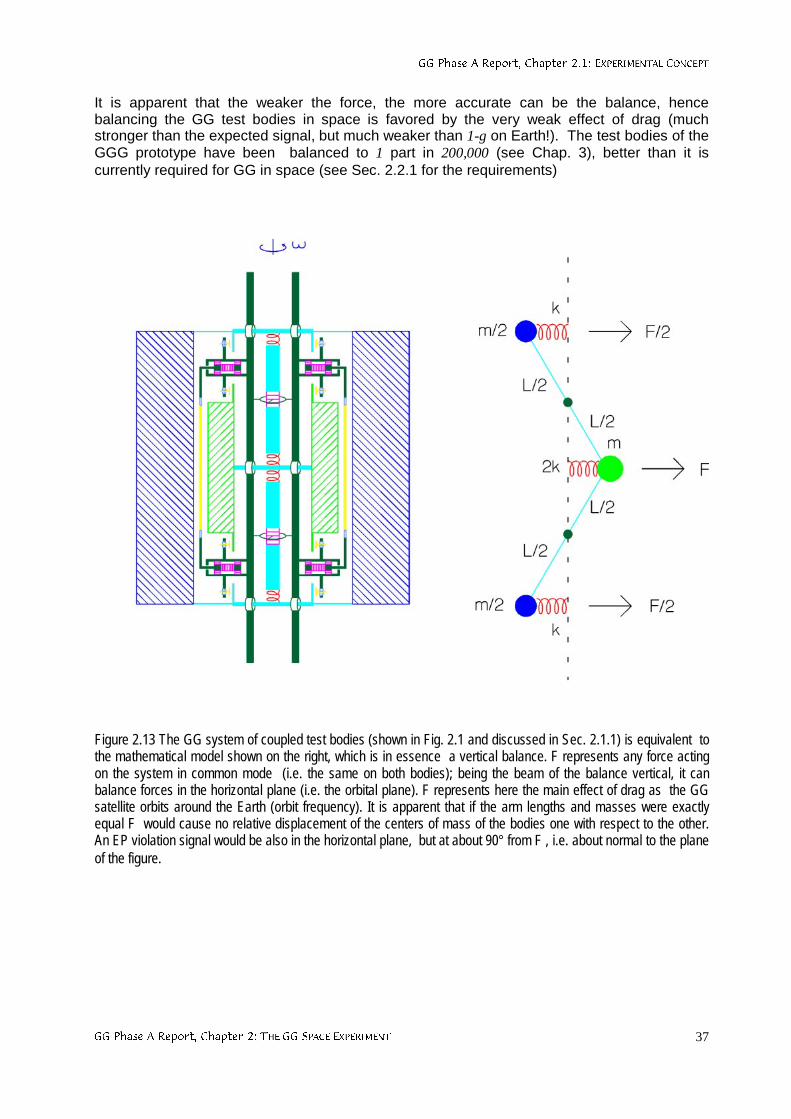
**3KDVH$5HSRUW&KDSWHU(;3(5,0(17$/&21&(37
**3KDVH$5HSRUW&KDSWHU7+(**63$&((;3(5,0(17 37
It is apparent that the weaker the force, the more accurate can be the balance, hencebalancing the GG test bodies in space is favored by the very weak effect of drag (muchstronger than the expected signal, but much weaker than 1-g on Earth!). The test bodies of theGGG prototype have been balanced to 1 part in 200,000 (see Chap. 3), better than it iscurrently required for GG in space (see Sec. 2.2.1 for the requirements)
Figure 2.13 The GG system of coupled test bodies (shown in Fig. 2.1 and discussed in Sec. 2.1.1) is equivalent tothe mathematical model shown on the right, which is in essence a vertical balance. F represents any force actingon the system in common mode (i.e. the same on both bodies); being the beam of the balance vertical, it canbalance forces in the horizontal plane (i.e. the orbital plane). F represents here the main effect of drag as the GGsatellite orbits around the Earth (orbit frequency). It is apparent that if the arm lengths and masses were exactlyequal F would cause no relative displacement of the centers of mass of the bodies one with respect to the other.An EP violation signal would be also in the horizontal plane, but at about 90° from F , i.e. about normal to the planeof the figure.
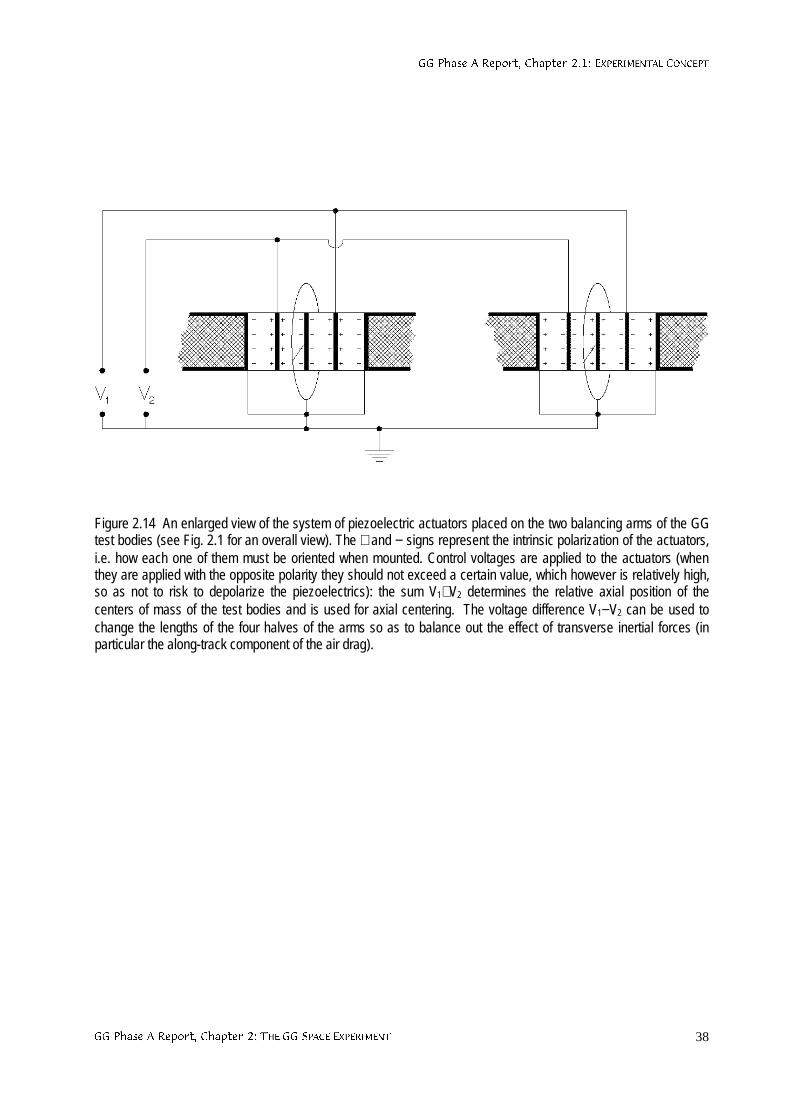
**3KDVH$5HSRUW&KDSWHU(;3(5,0(17$/&21&(37
**3KDVH$5HSRUW&KDSWHU7+(**63$&((;3(5,0(17 38
Figure 2.14 An enlarged view of the system of piezoelectric actuators placed on the two balancing arms of the GGtest bodies (see Fig. 2.1 for an overall view). The + and − signs represent the intrinsic polarization of the actuators,i.e. how each one of them must be oriented when mounted. Control voltages are applied to the actuators (whenthey are applied with the opposite polarity they should not exceed a certain value, which however is relatively high,so as not to risk to depolarize the piezoelectrics): the sum V1+V2 determines the relative axial position of thecenters of mass of the test bodies and is used for axial centering. The voltage difference V1−V2 can be used tochange the lengths of the four halves of the arms so as to balance out the effect of transverse inertial forces (inparticular the along-track component of the air drag).
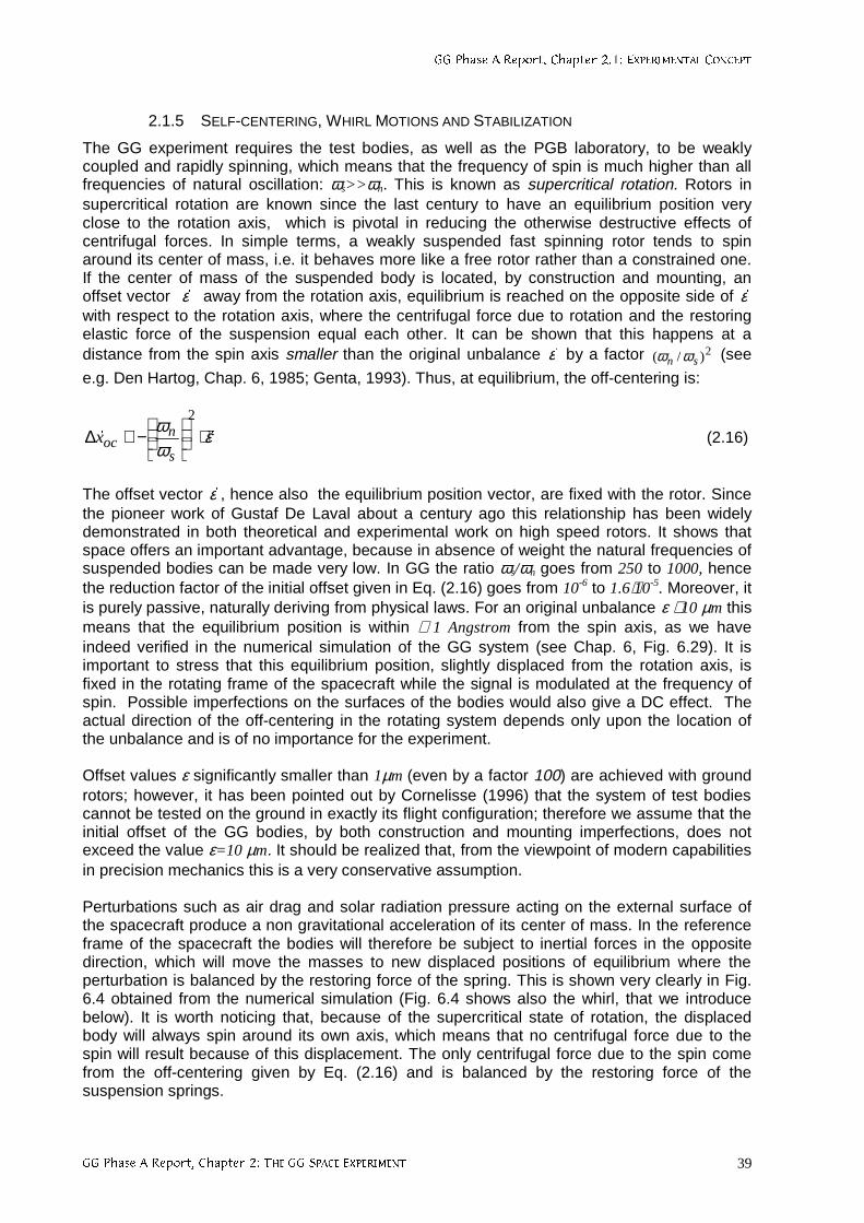
**3KDVH$5HSRUW&KDSWHU(;3(5,0(17$/&21&(37
**3KDVH$5HSRUW&KDSWHU7+(**63$&((;3(5,0(17 39
2.1.5 SELF-CENTERING, WHIRL MOTIONS AND STABILIZATION
The GG experiment requires the test bodies, as well as the PGB laboratory, to be weaklycoupled and rapidly spinning, which means that the frequency of spin is much higher than allfrequencies of natural oscillation: ωs>>ωn. This is known as supercritical rotation. Rotors insupercritical rotation are known since the last century to have an equilibrium position veryclose to the rotation axis, which is pivotal in reducing the otherwise destructive effects ofcentrifugal forces. In simple terms, a weakly suspended fast spinning rotor tends to spinaround its center of mass, i.e. it behaves more like a free rotor rather than a constrained one.If the center of mass of the suspended body is located, by construction and mounting, anoffset vector εr away from the rotation axis, equilibrium is reached on the opposite side of εr
with respect to the rotation axis, where the centrifugal force due to rotation and the restoringelastic force of the suspension equal each other. It can be shown that this happens at adistance from the spin axis smaller than the original unbalance εr by a factor 2)/( sn ωω (see
e.g. Den Hartog, Chap. 6, 1985; Genta, 1993). Thus, at equilibrium, the off-centering is:
εωω rr ⋅
−≅∆
2
s
nocx (2.16)
The offset vector εr , hence also the equilibrium position vector, are fixed with the rotor. Sincethe pioneer work of Gustaf De Laval about a century ago this relationship has been widelydemonstrated in both theoretical and experimental work on high speed rotors. It shows thatspace offers an important advantage, because in absence of weight the natural frequencies ofsuspended bodies can be made very low. In GG the ratio ωs/ωn goes from 250 to 1000, hencethe reduction factor of the initial offset given in Eq. (2.16) goes from 10-6 to 1.6⋅10-5. Moreover, itis purely passive, naturally deriving from physical laws. For an original unbalance ε ≅10 µm thismeans that the equilibrium position is within ≅ 1 Angstrom from the spin axis, as we haveindeed verified in the numerical simulation of the GG system (see Chap. 6, Fig. 6.29). It isimportant to stress that this equilibrium position, slightly displaced from the rotation axis, isfixed in the rotating frame of the spacecraft while the signal is modulated at the frequency ofspin. Possible imperfections on the surfaces of the bodies would also give a DC effect. Theactual direction of the off-centering in the rotating system depends only upon the location ofthe unbalance and is of no importance for the experiment.
Offset values ε significantly smaller than 1µm (even by a factor 100) are achieved with groundrotors; however, it has been pointed out by Cornelisse (1996) that the system of test bodiescannot be tested on the ground in exactly its flight configuration; therefore we assume that theinitial offset of the GG bodies, by both construction and mounting imperfections, does notexceed the value ε=10 µm. It should be realized that, from the viewpoint of modern capabilitiesin precision mechanics this is a very conservative assumption.
Perturbations such as air drag and solar radiation pressure acting on the external surface ofthe spacecraft produce a non gravitational acceleration of its center of mass. In the referenceframe of the spacecraft the bodies will therefore be subject to inertial forces in the oppositedirection, which will move the masses to new displaced positions of equilibrium where theperturbation is balanced by the restoring force of the spring. This is shown very clearly in Fig.6.4 obtained from the numerical simulation (Fig. 6.4 shows also the whirl, that we introducebelow). It is worth noticing that, because of the supercritical state of rotation, the displacedbody will always spin around its own axis, which means that no centrifugal force due to thespin will result because of this displacement. The only centrifugal force due to the spin comefrom the off-centering given by Eq. (2.16) and is balanced by the restoring force of thesuspension springs.
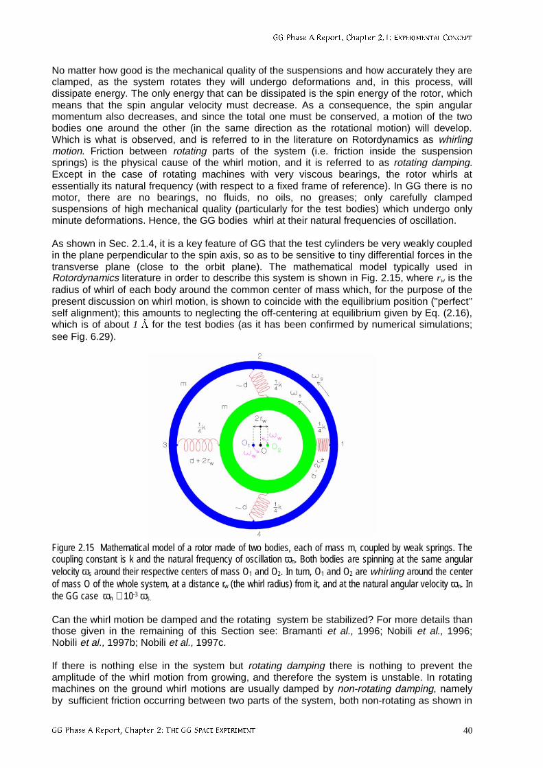
**3KDVH$5HSRUW&KDSWHU(;3(5,0(17$/&21&(37
**3KDVH$5HSRUW&KDSWHU7+(**63$&((;3(5,0(17 40
No matter how good is the mechanical quality of the suspensions and how accurately they areclamped, as the system rotates they will undergo deformations and, in this process, willdissipate energy. The only energy that can be dissipated is the spin energy of the rotor, whichmeans that the spin angular velocity must decrease. As a consequence, the spin angularmomentum also decreases, and since the total one must be conserved, a motion of the twobodies one around the other (in the same direction as the rotational motion) will develop.Which is what is observed, and is referred to in the literature on Rotordynamics as whirlingmotion. Friction between rotating parts of the system (i.e. friction inside the suspensionsprings) is the physical cause of the whirl motion, and it is referred to as rotating damping.Except in the case of rotating machines with very viscous bearings, the rotor whirls atessentially its natural frequency (with respect to a fixed frame of reference). In GG there is nomotor, there are no bearings, no fluids, no oils, no greases; only carefully clampedsuspensions of high mechanical quality (particularly for the test bodies) which undergo onlyminute deformations. Hence, the GG bodies whirl at their natural frequencies of oscillation.
As shown in Sec. 2.1.4, it is a key feature of GG that the test cylinders be very weakly coupledin the plane perpendicular to the spin axis, so as to be sensitive to tiny differential forces in thetransverse plane (close to the orbit plane). The mathematical model typically used inRotordynamics literature in order to describe this system is shown in Fig. 2.15, where rw is theradius of whirl of each body around the common center of mass which, for the purpose of thepresent discussion on whirl motion, is shown to coincide with the equilibrium position ("perfect’’self alignment); this amounts to neglecting the off-centering at equilibrium given by Eq. (2.16),which is of about 1 for the test bodies (as it has been confirmed by numerical simulations;see Fig. 6.29).
Figure 2.15 Mathematical model of a rotor made of two bodies, each of mass m, coupled by weak springs. Thecoupling constant is k and the natural frequency of oscillation ωn. Both bodies are spinning at the same angularvelocity ωs around their respective centers of mass O1 and O2. In turn, O1 and O2 are whirling around the centerof mass O of the whole system, at a distance rw (the whirl radius) from it, and at the natural angular velocity ωn. Inthe GG case ωn ≅ 10-3 ωs.
Can the whirl motion be damped and the rotating system be stabilized? For more details thanthose given in the remaining of this Section see: Bramanti et al., 1996; Nobili et al., 1996;Nobili et al., 1997b; Nobili et al., 1997c.
If there is nothing else in the system but rotating damping there is nothing to prevent theamplitude of the whirl motion from growing, and therefore the system is unstable. In rotatingmachines on the ground whirl motions are usually damped by non-rotating damping, namelyby sufficient friction occurring between two parts of the system, both non-rotating as shown in
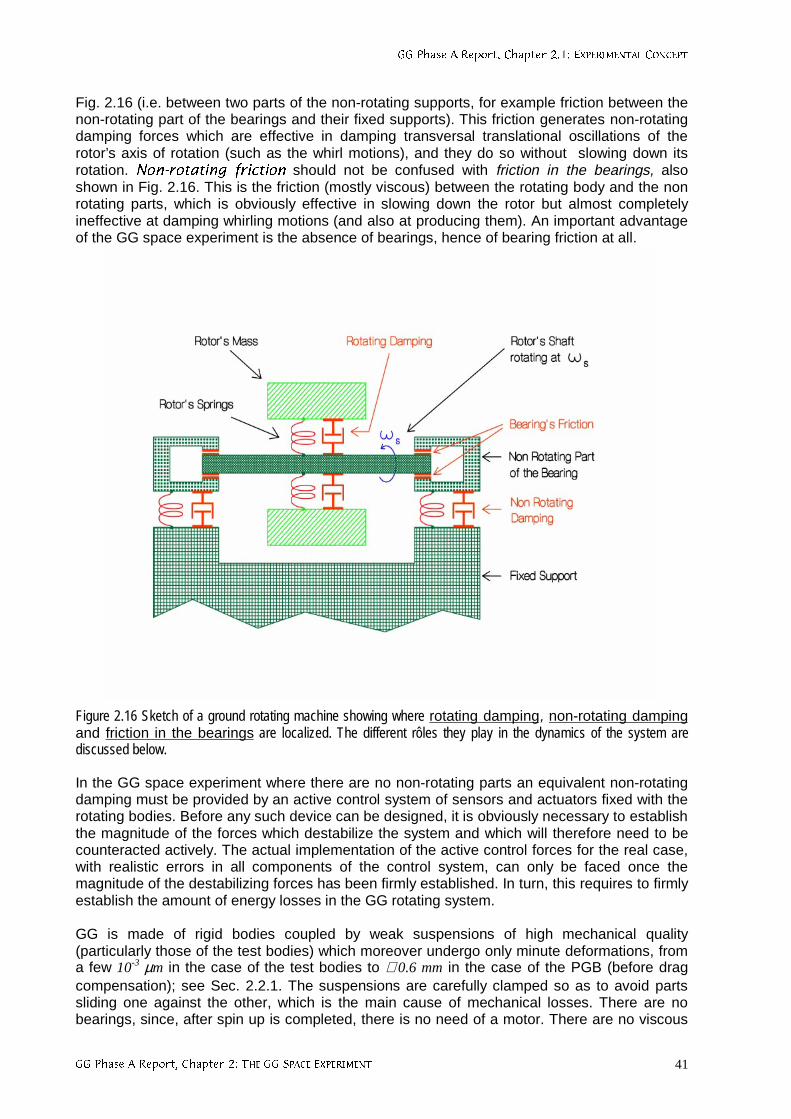
**3KDVH$5HSRUW&KDSWHU(;3(5,0(17$/&21&(37
**3KDVH$5HSRUW&KDSWHU7+(**63$&((;3(5,0(17 41
Fig. 2.16 (i.e. between two parts of the non-rotating supports, for example friction between thenon-rotating part of the bearings and their fixed supports). This friction generates non-rotatingdamping forces which are effective in damping transversal translational oscillations of therotor’s axis of rotation (such as the whirl motions), and they do so without slowing down itsrotation. 1RQURWDWLQJ IULFWLRQ should not be confused with friction in the bearings, alsoshown in Fig. 2.16. This is the friction (mostly viscous) between the rotating body and the nonrotating parts, which is obviously effective in slowing down the rotor but almost completelyineffective at damping whirling motions (and also at producing them). An important advantageof the GG space experiment is the absence of bearings, hence of bearing friction at all.
Figure 2.16 Sketch of a ground rotating machine showing where rotating damping, non-rotating dampingand friction in the bearings are localized. The different rôles they play in the dynamics of the system arediscussed below.
In the GG space experiment where there are no non-rotating parts an equivalent non-rotatingdamping must be provided by an active control system of sensors and actuators fixed with therotating bodies. Before any such device can be designed, it is obviously necessary to establishthe magnitude of the forces which destabilize the system and which will therefore need to becounteracted actively. The actual implementation of the active control forces for the real case,with realistic errors in all components of the control system, can only be faced once themagnitude of the destabilizing forces has been firmly established. In turn, this requires to firmlyestablish the amount of energy losses in the GG rotating system.
GG is made of rigid bodies coupled by weak suspensions of high mechanical quality(particularly those of the test bodies) which moreover undergo only minute deformations, froma few 10-3 µm in the case of the test bodies to ≅ 0.6 mm in the case of the PGB (before dragcompensation); see Sec. 2.2.1. The suspensions are carefully clamped so as to avoid partssliding one against the other, which is the main cause of mechanical losses. There are nobearings, since, after spin up is completed, there is no need of a motor. There are no viscous
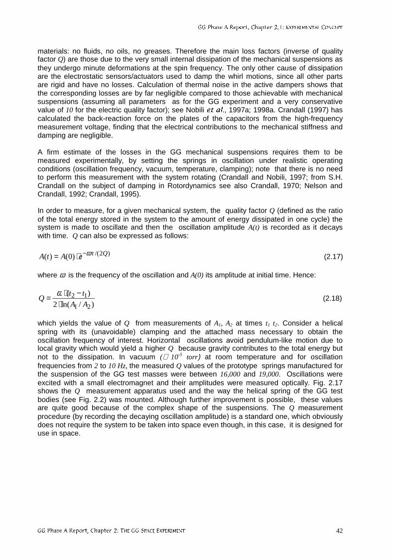
**3KDVH$5HSRUW&KDSWHU(;3(5,0(17$/&21&(37
**3KDVH$5HSRUW&KDSWHU7+(**63$&((;3(5,0(17 42
materials: no fluids, no oils, no greases. Therefore the main loss factors (inverse of qualityfactor Q) are those due to the very small internal dissipation of the mechanical suspensions asthey undergo minute deformations at the spin frequency. The only other cause of dissipationare the electrostatic sensors/actuators used to damp the whirl motions, since all other partsare rigid and have no losses. Calculation of thermal noise in the active dampers shows thatthe corresponding losses are by far negligible compared to those achievable with mechanicalsuspensions (assuming all parameters as for the GG experiment and a very conservativevalue of 10 for the electric quality factor); see Nobili HWDO., 1997a; 1998a. Crandall (1997) hascalculated the back-reaction force on the plates of the capacitors from the high-frequencymeasurement voltage, finding that the electrical contributions to the mechanical stiffness anddamping are negligible.
A firm estimate of the losses in the GG mechanical suspensions requires them to bemeasured experimentally, by setting the springs in oscillation under realistic operatingconditions (oscillation frequency, vacuum, temperature, clamping); note that there is no needto perform this measurement with the system rotating (Crandall and Nobili, 1997; from S.H.Crandall on the subject of damping in Rotordynamics see also Crandall, 1970; Nelson andCrandall, 1992; Crandall, 1995).
In order to measure, for a given mechanical system, the quality factor Q (defined as the ratioof the total energy stored in the system to the amount of energy dissipated in one cycle) thesystem is made to oscillate and then the oscillation amplitude A(t) is recorded as it decayswith time. Q can also be expressed as follows:
)2/()0()( QteAtA ω−⋅= (2.17)
where ω is the frequency of the oscillation and A(0) its amplitude at initial time. Hence:
)/ln(2
)(
21
12
AA
ttQ
⋅−⋅= ω
(2.18)
which yields the value of Q from measurements of A1, A2 at times t1 t2. Consider a helicalspring with its (unavoidable) clamping and the attached mass necessary to obtain theoscillation frequency of interest. Horizontal oscillations avoid pendulum-like motion due tolocal gravity which would yield a higher Q because gravity contributes to the total energy butnot to the dissipation. In vacuum (≅ 10-5 torr) at room temperature and for oscillationfrequencies from 2 to 10 Hz, the measured Q values of the prototype springs manufactured forthe suspension of the GG test masses were between 16,000 and 19,000. Oscillations wereexcited with a small electromagnet and their amplitudes were measured optically. Fig. 2.17shows the Q measurement apparatus used and the way the helical spring of the GG testbodies (see Fig. 2.2) was mounted. Although further improvement is possible, these valuesare quite good because of the complex shape of the suspensions. The Q measurementprocedure (by recording the decaying oscillation amplitude) is a standard one, which obviouslydoes not require the system to be taken into space even though, in this case, it is designed foruse in space.
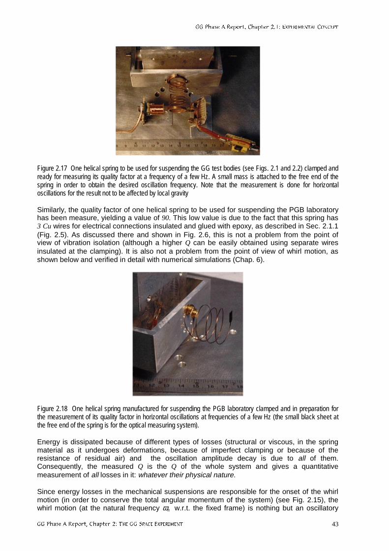
**3KDVH$5HSRUW&KDSWHU(;3(5,0(17$/&21&(37
**3KDVH$5HSRUW&KDSWHU7+(**63$&((;3(5,0(17 43
Figure 2.17 One helical spring to be used for suspending the GG test bodies (see Figs. 2.1 and 2.2) clamped andready for measuring its quality factor at a frequency of a few Hz. A small mass is attached to the free end of thespring in order to obtain the desired oscillation frequency. Note that the measurement is done for horizontaloscillations for the result not to be affected by local gravity
Similarly, the quality factor of one helical spring to be used for suspending the PGB laboratoryhas been measure, yielding a value of 90. This low value is due to the fact that this spring has3 Cu wires for electrical connections insulated and glued with epoxy, as described in Sec. 2.1.1(Fig. 2.5). As discussed there and shown in Fig. 2.6, this is not a problem from the point ofview of vibration isolation (although a higher Q can be easily obtained using separate wiresinsulated at the clamping). It is also not a problem from the point of view of whirl motion, asshown below and verified in detail with numerical simulations (Chap. 6).
Figure 2.18 One helical spring manufactured for suspending the PGB laboratory clamped and in preparation forthe measurement of its quality factor in horizontal oscillations at frequencies of a few Hz (the small black sheet atthe free end of the spring is for the optical measuring system).
Energy is dissipated because of different types of losses (structural or viscous, in the springmaterial as it undergoes deformations, because of imperfect clamping or because of theresistance of residual air) and the oscillation amplitude decay is due to all of them.Consequently, the measured Q is the Q of the whole system and gives a quantitativemeasurement of all losses in it: whatever their physical nature.
Since energy losses in the mechanical suspensions are responsible for the onset of the whirlmotion (in order to conserve the total angular momentum of the system) (see Fig. 2.15), thewhirl motion (at the natural frequency ωn w.r.t. the fixed frame) is nothing but an oscillatory
**3KDVH$5HSRUW&KDSWHU(;3(5,0(17$/&21&(37
**3KDVH$5HSRUW&KDSWHU7+(**63$&((;3(5,0(17 44
motion of growing amplitude, i.e. with a negative quality factor equal and opposite to themeasured quality factor Q of the suspensions. Hence, the radius of whirl will grow, from agiven initial value rw(0), according to the equation:
Qtww
nertr 2/)0()( ω⋅= (2.19)
That is, the larger the Q, the slower the growth of the whirl instability. For large Q, as in thiscase, we can write:
( )Qr
rnTw π≅
∆ (2.20)
where (∆rw)Tn is the increase in the amplitude of whirl in one natural period of oscillation Tn. Forthe GG test bodies, taking the measured value Q ≅ 19,000 and having Tn ≅ 113 sec (see Sec.6.1.10), the amplitude of the whirl motion will need 8 days to double: such a very slow growth ofthe whirl instability is obviously very important for making the control forces required to damp itvery small. For the PGB, with a Q value of 90 and a natural period of oscillation of about 300sec the amplitude of the whirl motion needs about 2.4 hours to double; clearly, the whirl motionof the PGB grows much faster than the whirl motion of the test bodies due to the much poorermechanical quality of its suspensions. However, it is still very slow compared to the spin andthere is no problem in controlling it, as it is found in Chap. 6. The disturbing force resultingfrom inaccurate application of the PGB control force acts as a common mode disturbance onthe test bodies (platform noise) and it is found to be negligible (see Sec. 2.2.6).
The increase in amplitude (∆rw)Tn (during one natural period) is due to an increase of thealong-track velocity of the bodies, which in turn is caused by an average destabilizingacceleration ad, also along-track, such that:
( )nTwnd rTa ∆⋅≅⋅⋅ π2
2
1 2 , wnd rQ
a ⋅⋅≅ 21 ω (2.21)
which means, an average destabilizing force (along-track) of magnitude
w2nd rm
Q
1F ⋅ω⋅⋅≅ (2.22)
Since w2nc rmF ⋅ω⋅= is the centrifugal force, equal and opposite to the elastic force of the
spring wspring rkF ⋅−= , the destabilizing force which generates the unstable whirl motion
depicted in Fig. 2.15 turns out to be
springd FQ
1F ⋅≅ (2.23)
i.e., only a fraction of the elastic spring force: the higher is the Q of the suspensions (at thespin frequency) the smaller is the destabilizing force which needs to be damped in order tostabilize the system. This is well known in Rotordynamics.
The following question becomes relevant at this point: how much energy (per unit time) isgained by the (destabilizing) whirling motion as fraction of the energy lost by the spinningrotor? Let us consider the rotor in the two body model of Fig. 2.15. The spin energy of the rotoris:
**3KDVH$5HSRUW&KDSWHU(;3(5,0(17$/&21&(37
**3KDVH$5HSRUW&KDSWHU7+(**63$&((;3(5,0(17 45
2srotor I
2
1E ω⋅⋅= (2.24)
I is the total moment of inertia of the two bodies with respect to the spin axis (perpendicular tothe plane of the Figure). The energy (kinetic plus elastic) of the whirl motion, at the constantnatural frequency ωn with respect to the fixed frame and with radius of whirl rw is:
2w
2nw rm2E ⋅ω⋅⋅= (2.25)
The time derivatives of Ew and Erotor are:
w2nww rrm4E &
& ⋅ω⋅⋅⋅= , ssrotor IE ω⋅ω⋅= &
& (2.26)
From the conservation of angular momentum it is possible to relate sω& to wr& . The total spin
angular momentum of the rotor is:
srotor IL ω⋅= (2.27)
The angular momentum of the whirl motion is:
n2ww rm2L ω⋅⋅⋅= (2.28)
Since the total angular momentum has to be conserved, it must be:
0LL wrotor =+ && (2.29)
from which, since ωn is constant, it follows:
wnw
s rI
rm&& ⋅⋅⋅⋅−= ωω 4
(2.30)
Using Eq. (2.30) for sω& , we get from Eq. (2.26):
s
n
rotor
w
E
E
ωω
−=&
&
(2.31)
which is a very important result. In the GG case, where the frequency of the whirl motion isvery small compared to the spin frequency (ωn ≅10-3 ωs), Eq. (2.31) tells us that the energygained by the whirling motion is one thousand times smaller than the energy lost by the rotor.All the rest, that is 1-(ωn/ωs) ≅ 99.9%!! is dissipated as heat inside the springs; which meansthat it is not transferred to the (destabilizing) whirl motion. In simple terms one can say that in"supercritical’’ rotation the energy balance is essentially between the rotor and the springs; therotor looses spin energy and the springs dissipate almost all of it as heat: the faster is the spin,the larger is the energy dissipated inside the springs, as it can be seen from Eq. (2.26). On theother hand, the springs do not enter at all in the balance of the angular momentum; the onsetof the whirl motion is inevitable for the total angular momentum to be conserved, but theenergy it gains from the rotor is only the small fraction given by Eq. (2.31). So, the idea onemight have that the faster the spin (as compared to the natural frequency) the higher theenergy gained also by the whirl motion (by which argument the GG system would be highly
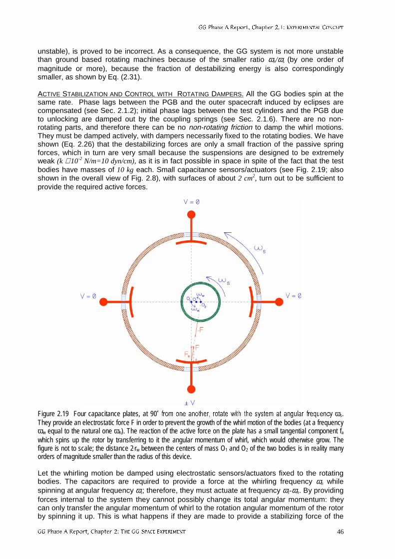
**3KDVH$5HSRUW&KDSWHU(;3(5,0(17$/&21&(37
**3KDVH$5HSRUW&KDSWHU7+(**63$&((;3(5,0(17 46
unstable), is proved to be incorrect. As a consequence, the GG system is not more unstablethan ground based rotating machines because of the smaller ratio ωn/ωs (by one order ofmagnitude or more), because the fraction of destabilizing energy is also correspondinglysmaller, as shown by Eq. (2.31).
ACTIVE STABILIZATION AND CONTROL WITH ROTATING DAMPERS. All the GG bodies spin at thesame rate. Phase lags between the PGB and the outer spacecraft induced by eclipses arecompensated (see Sec. 2.1.2); initial phase lags between the test cylinders and the PGB dueto unlocking are damped out by the coupling springs (see Sec. 2.1.6). There are no non-rotating parts, and therefore there can be no non-rotating friction to damp the whirl motions.They must be damped actively, with dampers necessarily fixed to the rotating bodies. We haveshown (Eq. 2.26) that the destabilizing forces are only a small fraction of the passive springforces, which in turn are very small because the suspensions are designed to be extremelyweak (k ≅ 10-2 N/m=10 dyn/cm), as it is in fact possible in space in spite of the fact that the testbodies have masses of 10 kg each. Small capacitance sensors/actuators (see Fig. 2.19; alsoshown in the overall view of Fig. 2.8), with surfaces of about 2 cm2, turn out to be sufficient toprovide the required active forces.
Figure 2.19 Four capacitance plates, at 90Û IURPRQHDQRWKHU URWDWHZLWK WKH V\VWHPDW DQJXODU IUHTXHQF\ωs.They provide an electrostatic force F in order to prevent the growth of the whirl motion of the bodies (at a frequencyωw equal to the natural one ωn). The reaction of the active force on the plate has a small tangential component fawhich spins up the rotor by transferring to it the angular momentum of whirl, which would otherwise grow. Thefigure is not to scale; the distance 2.rw between the centers of mass O1 and O2 of the two bodies is in reality manyorders of magnitude smaller than the radius of this device.
Let the whirling motion be damped using electrostatic sensors/actuators fixed to the rotatingbodies. The capacitors are required to provide a force at the whirling frequency ωn whilespinning at angular frequency ωs; therefore, they must actuate at frequency ωs-ωn. By providingforces internal to the system they cannot possibly change its total angular momentum: theycan only transfer the angular momentum of whirl to the rotation angular momentum of the rotorby spinning it up. This is what happens if they are made to provide a stabilizing force of the
**3KDVH$5HSRUW&KDSWHU(;3(5,0(17$/&21&(37
**3KDVH$5HSRUW&KDSWHU7+(**63$&((;3(5,0(17 47
same intensity as the destabilizing one given by Eq. (2.23) (in fact a slightly larger one). Thisforce must always act along the vector of relative velocity of the centers of mass of the bodiesin their whirling motion, as seen in the fixed frame of reference. Since the centers of mass ofthe bodies are displaced from the center of mass of the system by an amount rw (see Fig.2.19), the electrostatic plates will necessarily apply also a small force fa tangent to he surfaceof the rotor amounting to a fraction rw/R (R ≅ 10 cm is the linear dimension of the rotor) of theactive force F, of intensity F ≅ (2/Q).|Fspring| (for both bodies), which will damp the relativevelocity of whirl (see Fig. 2.19). Of the corresponding reaction components on the electrostaticactuators only the reaction to the small tangential component fa ≅ (1/Q).|Fspring|
.(2rw/R) willproduce a non zero angular momentum by spinning up the rotor at the expense of exactly theangular momentum of whirl:
w2w
2nwspringa Lrm2
Q
1r2F
Q
1Rf &=⋅ω⋅⋅⋅≅⋅⋅⋅≅⋅ (2.32)
which will therefore increase the spin angular momentum of the rotor Lrotor = I.ωs in such a waythat the total angular momentum of the system is conserved. That is:
2w
2ns rm2
Q
1I ⋅ω⋅⋅⋅≅ω⋅ & (2.32)
thus producing a spin up of the rotor at the rate sω& given by Eq. (2.32) By integrating sω& for
the entire duration of the mission Tmission= tf- ti , from intial to final epoch, the ratio ωf/ωi of final-to-initial spin angular velocity of the rotor is obtained:
mission2i
2n
2wi
i
fT
I
rm2
Q1 ⋅
ω
ω⋅
⋅⋅⋅
ω+=
ωω
(2.33)
In the case of the GG test bodies, taking the measured value of 19,000 for the quality factor Qat the spin frequency of 2Hz, rw ≅ 10-2 µm (although whirl radii are damped below this value)and 62
spin2n 105.2/ −⋅≅ωω we get, for a 7 month duration of the mission:
15
i
f101 −≅−
ω
ω(2.34)
The corresponding angular advance is negligible. The amount of spin energy gained by therotor at the end of the mission is vanishingly small. The corresponding (negative) quality factorfor the spin up of the rotor (in absence of any external disturbances to its spin rate) isobviously huge (in modulus). The amount of spin angular momentum gained by the rotor in 6months is, similarly to the spin energy, vanishingly small.
The contribution to the energy of the system by the electrostatic dampers is obtained bycomputing the work done by both components (Fa and fa, shown in Fig. 2.17) of the activeforce they provide. While only fa will transfer angular momentum from the whirl motion to therotor, both components of the active force will provide energy. It can be easily demonstratedthat fa supplies the rotor with the energy necessary to increase its spin rate, while the energysupplied by Fa balances exactly the energy dissipated by the springs as heat, which wouldotherwise slow down the rotor.
The capacitors must also act as sensors in order to recover, from relative positionmeasurements, the linear relative velocity of the whirling motion which needs to be damped to
**3KDVH$5HSRUW&KDSWHU(;3(5,0(17$/&21&(37
**3KDVH$5HSRUW&KDSWHU7+(**63$&((;3(5,0(17 48
stabilize the system; or, for example (see Fig. 2.19), two of the capacitors can be used assensors and the other two as actuators. In GG the capacitors spin (together with the bodies) ata frequency about 103 times larger than the frequency of whirl. Is it possible, by means ofrotating sensors, to recover the slow relative velocity of whirl as with non-rotating sensors?This question can be answered in a totally general way. The answer would be "No", if therotating observer had no other means of "looking outside" to measure independently (i.e. bymeans of some other instrument) its own phase and rotation rate; the answer is "Yes", if therotating observer can do that, which is the case in GG using Earth Elevation Sensors (seeSec. 5.5). An independent knowledge of the phase and the rotation rate of the sensors makesit possible to subtract from the measurements of the rotating sensors their own velocity ofrotation, hence to recover the (much slower) relative velocity which would be obtained withfixed sensors. The problem amounts to that of computing numerically a time derivative,because the capacitors measure relative displacements while the electrostatic active dampersrequire to know the relative velocity of the bodies in the fixed frame. If the velocity werecomputed by taking successive measurements of the sensors and computing their difference,it would be dominated by the rotation velocity, i.e. it would be larger than the velocity to bedamped by a factor about 103 (i.e. the ratio spin-to-natural velocity). If then such a velocityoutput were used to drive the electrostatic actuators which must damp it, the required forcewould be (correspondingly) about 103 times larger than necessary. Clearly this procedurewould not be appropriate for a system like GG where the spin-to-natural velocity ratio is verylarge.
Instead, the problem of reducing the magnitude of the active control forces close to that of thedestabilizing ones (given by Eq. 2.23), is solved as follows. A reference signal is built from a 2Hz oscillator (clock) synchronized by the Earth Elevation Sensors output averaged over manyspin periods of the spacecraft. Since the spin period is 0.5 sec, it can certainly be consideredconstant over time intervals of the order of many times the spin period itself. Note that thereference signal is continuously synchronized to the output of the Earth Elevation Sensors sothat any error in their measurement of the spin rate will not build up. The reference signal isneeded in order to perform the transformation from the rotating to the fixed frame (and back)as accurately as possible. A relative displacement of two bodies due to the growing unstablemode is measured by the rotating capacitance sensors. Instead of taking successivemeasurements of the sensors and computing their difference, the difference is computedbetween measurements which are 1 spin period apart, using the reference signal. The sensorsignal is sampled a certain number of times per spin period (e.g. 10 to 20), at regular intervals,and for each sampled point the difference is computed with respect to the sampled point 1 spinperiod later. In this way the rotation velocity of the sensors is subtracted from theirmeasurements; a best fit to the sampled data points (each one is a relative position differenceafter 1 spin period) gives the relative velocity vector v
r
between the two bodies in the fixedframe. To this velocity corresponds a whirling motion of amplitude rw ≅ v/ωn, and then, takinginto account Eq. (2.22), we can obtain the required stabilizing force, anti-parallel to the velocityvr
,
vr
r
⋅⋅⋅−= nstab mQ
F ω1(2.35)
This force will prevent the whirl motion from growing, i.e. it will maintain the system in a steadycondition. To actually damp a whirling motion one has to apply a slightly larger force: forinstance, a force twice as large will damp the whirling motion at the same rate at which itwould grow in the absence of stabF
r
.
Were the capacitance sensors perfect, this would be enough to stabilize the GG bodies, as itcan be also checked with numerical simulations. However, the sensitivity of the sensors inrealistic flight conditions has to be taken into account because, being the growth rate of thewhirl instabilities very slow, the relative displacement during one spin period is so small to be

**3KDVH$5HSRUW&KDSWHU(;3(5,0(17$/&21&(37
**3KDVH$5HSRUW&KDSWHU7+(**63$&((;3(5,0(17 49
dominated by the noise of the sensors. As a result, the recovered velocity vector is also verynoisy, and much larger than its actual value in the fixed frame. If the actuators wereprogrammed to damp the velocity vector recovered in this way, the resulting active force wouldbe driven by the noise, i.e. it would be much larger than the force which destabilizes thesystem. Such a controlled system would be dominated by the active control forces rather thanby the very low stiffness passive mechanical suspensions. This is in contrast with the basicphysical design of the GG experimental test of the universality of free fall whereby the testbodies must be very weakly coupled so as to be sensitive to tiny differential forces.
A better active control can be devised in which active damping is not applied until the (slow)relative velocity of the whirl motion of the bodies has been recovered from the noise afterappropriate averaging. To do this, the relative velocity vector is averaged over a few spinperiods (typically a fraction 1/100 of one period of whirl), and then fitted to the whirl period (thenatural period of oscillation) in order to reconstruct its rotation in the fixed frame. Since thegrowth rate of the instability is slow, this averaging procedure can be carried on over a largenumber of whirl periods (particularly for the test bodies), thus making the determination of thevelocity to be damped more and more accurate. Active control starts only once the smallrelative velocity of the bodies w.r.t. the fixed frame has been reconstructed and separated fromthe noise.
So far we have outlined the main principles on which active control of the whirl motions shouldbe based. A dynamical control which allows stabilization of the whirl motions (as well as dragcompensation according to the requirements) has been designed and implemented in a finiteelement numerical simulation of the full GG system. The results are reported in Chap. 6 andare fully satisfactory. They demonstrate beyond question that the analysis of GG by Jafry andWeinberger (1998), whereby GG would be limited by the active control forces to an accuracyof 1 part in 1014 in EP testing (3 orders of magnitude worse than the GG target), is incorrectbecause their dynamical control is badly designed (see also Nobili et al.,1998b).
**3KDVH$5HSRUW&KDSWHU(;3(5,0(17$/&21&(37
**3KDVH$5HSRUW&KDSWHU7+(**63$&((;3(5,0(17 50
2.1.6 LOCKING/UNLOCKING
All space experiments which involve freely falling or softly suspended bodies require them tobe locked during launch, and properly unlocked once in orbit to start the experiment. First of allwe find it important to avoid any danger of the rotors hitting each other. This is done simply byhaving each suspended mass and the PGB laboratory constrained to only slight movements inall directions by means of mechanical stops Fig. 4.3 shows, for instance, the mechanical stopsbetween the outer test cylinder and the PGB tube. Static lockers capable to survive the launchphase have been designed both for the PGB (Sec. 5.2) and the test bodies (Sec. 4.1). As forthe forces acting on the springs themselves during launch, their mass is very small andestimates show that there is no danger for the elasticity regime to be exceeded during launch;some time for relaxation should probably be allowed at the beginning of the mission. Once thespacecraft has been injected in its orbit and given the required attitude and spin rate staticlockers can be released and never used again. A symmetrical locking consisting of 4 inch-worms placed at 90° from one another as shown in Fig. 2.20 is provided, centering thecylindrical bodies to within their original construction and mounting error ε ≅10 µm (see Sec.2.1.5). Each inch-worm is equipped with a force sensor sensitive to 10 µN (easy, e.g. with aspring force sensor) giving a measure of the centrifugal force in that direction, and thereforeproviding the driving signal to the inch-worms for reducing the distance offset from the rotationaxis. Once the off centering has been reduced to ≅ 10-9 m, which means a centrifugal force of10 µN for the PGB, active centering with inch-worms can be stopped; the electrostatic damperswill then stabilize whirl motions around the equilibrium positions (see Sec. 2.1.5 and Chap. 6).While the static lockers are meant not to be reused, the inch-worms can be reused to re-centerthe system if anything happens during the mission. Together with the mechanical stops theymake the system safe from unexpected occurrences.
The inch-worm unlocking should be done without transferring spin angular momentum to thebodies, which would induce undesired differential rotations. Ideally, the rotational torqueprovided by inch-worms placed at 90° from one another and pointing exactly towards thecentral axis, is exactly zero. This is why this configuration of the inch-worms has been chosen.The time required to provide the required force is very short (order of seconds). In practicehowever, there will be both angular and linear offsets from the ideal inch-worm configurationresulting in a non zero rotational, spurious torque whose effect on the springs which couple thebodies must be carefully evaluated. Most of the spurious torque is induced at the beginning ofthe inch-worm unlocking, when the off-centering of the body is dictated by the offset ε of thetest bodies due to construction and mounting imperfections. Assuming, for the angular andlinear offsets of the inch-worms 0.1 rad (6°) and 1 mm (both very conservative with modernprecision mechanics), and a continuos control time of 50 sec, the resulting spurious phase lagis 0.01 rad. Such a small phase lag, obtained under conservative assumptions, is reduced tozero by the torsion constant of the coupling springs over timescales of the order of 2 days forthe PGB and 2 weeks for the test masses (Comandi,1998).
The rôle of the coupling springs in damping out small phase lags between the PGB and theGG test bodies inside it, is very important and should not be overlooked. This is unlike thephase lags between the outer spacecraft and the PGB laboratory which are induced byeclipses every orbit; as discussed in Sec. 2.1.2, these phase lags are reduced almost entirelyby a passive mass compensation system, and the small remainder by FEEP control.
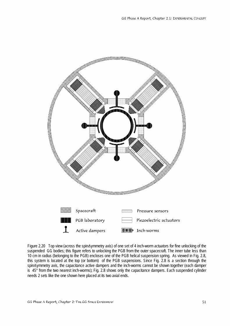
**3KDVH$5HSRUW&KDSWHU(;3(5,0(17$/&21&(37
**3KDVH$5HSRUW&KDSWHU7+(**63$&((;3(5,0(17 51
Figure 2.20 Top view (across the spin/symmetry axis) of one set of 4 inch-worm actuators for fine unlocking of thesuspended GG bodies; this figure refers to unlocking the PGB from the outer spacecraft. The inner tube less than10 cm in radius (belonging to the PGB) encloses one of the PGB helical suspension spring. As viewed in Fig. 2.8,this system is located at the top (or bottom) of the PGB suspensions. Since Fig. 2.8 is a section through thespin/symmetry axis, the capacitance active dampers and the inch-worms cannot be shown together (each damperis 45° from the two nearest inch-worms); Fig. 2.8 shows only the capacitance dampers. Each suspended cylinderneeds 2 sets like the one shown here placed at its two axial ends.
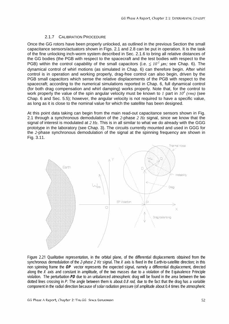
**3KDVH$5HSRUW&KDSWHU(;3(5,0(17$/&21&(37
**3KDVH$5HSRUW&KDSWHU7+(**63$&((;3(5,0(17 52
2.1.7 CALIBRATION PROCEDURE
Once the GG rotors have been properly unlocked, as outlined in the previous Section the smallcapacitance sensors/actuators shown in Figs. 2.1 and 2.8 can be put in operation. It is the taskof the fine unlocking inch-worm system described in Sec. 2.1.6 to bring all relative distances ofthe GG bodies (the PGB with respect to the spacecraft and the test bodies with respect to thePGB) within the control capability of the small capacitors (i.e. ¨ 10-2 µm; see Chap. 6). Thedynamical control of whirl motions (as simulated in Chap. 6) can therefore begin. After whirlcontrol is in operation and working properly, drag-free control can also begin, driven by thePGB small capacitors which sense the relative displacements of the PGB with respect to thespacecraft; according to the numerical simulations reported in Chap. 6, full dynamical control(for both drag compensation and whirl damping) works properly. Note that, for the control towork properly the value of the spin angular velocity must be known to 1 part in 104 (rms) (seeChap. 6 and Sec. 5.5); however, the angular velocity is not required to have a specific value,as long as it is close to the nominal value for which the satellite has been designed.
At this point data taking can begin from the main read-out capacitance sensors shown in Fig.2.1 through a synchronous demodulation of the 2-phase 2 Hz signal, since we know that thesignal of interest is modulated at 2 Hz. This is in all similar to what we do already with the GGGprototype in the laboratory (see Chap. 3). The circuits currently mounted and used in GGG forthe 2-phase synchronous demodulation of the signal at the spinning frequency are shown inFig. 3.11.
Figure 2.21 Qualitative representation, in the orbital plane, of the differential displacements obtained from thesynchronous demodulation of the 2-phase 2 Hz signal. The X axis is fixed in the Earth-to-satellite direction; in thisnon spinning frame the OP vector represents the expected signal, namely a differential displacement, directedalong the X axis and constant in amplitude, of the two masses due to a violation of the Equivalence Principleviolation. The perturbation PD due to an unbalanced atmospheric drag will be found in the area between the twodotted lines crossing in P: The angle between them is about 0.8 rad, due to the fact that the drag has a variablecomponent in the radial direction because of solar radiation pressure (of amplitude about 0.4 times the atmospheric
**3KDVH$5HSRUW&KDSWHU(;3(5,0(17$/&21&(37
**3KDVH$5HSRUW&KDSWHU7+(**63$&((;3(5,0(17 53
drag and in the Sun-satellite direction). Smaller contributions to the PD vector come from the Earth albedo, theEarth infrared radiation and, by a smaller amount, from a possible small eccentricity of the orbit. By finely adjustingthe lengths of the suspension arms (as discussed in Sec. 2.1.4) the point D is displaced up or down inside this area,and brought close to P. In doing so, also the radial component of the drag is automatically balanced, as pointed outin Sec. 2.1.4. The low frequency variations of the drag (not shown) will oscillate inside the same area. The vectorDQ shows here the whirl instability before it is damped by the whirl control whose period in this (non spinning)frame is the natural frequency of oscillation. The circle around point Q represents the error in the measurement dueto thermal noise of the mechanical oscillations built up during the integration time.
Large relative displacements of the test bodies will be detected at first. This means that eitherthe capacitance bridge is not balanced or the test masses are not balanced (i.e. disturbancesin common modes are not sufficiently rejected), or the axial misalignment between the centersof mass is too large (see the discussion on tidal disturbances, Sec. 2.2.2), or all of themtogether. The calibration phase consists in applying changes with the piezo actuators (to thecapacitance plates, the arms length of the test bodies and the axial positions of their centers ofmass) one by one, detecting the corresponding effect and from it deciding about the nextchange. Fig. 2.21 describes graphically how the signal is demodulated and the balancing iscarried out.
With the current requirement on thermal stability and on mechanical balancing of thecapacitance bridge the system may need re-balancing after 2 weeks (the mechanical balance ofthe bridge) and 20 days (balance of the test masses for common mode rejection). Axialcentering of the centers of mass of the test bodies needs to be done only at the beginning (seeSec. 2.2.2).
**3KDVH$5HSRUW&KDSWHU3(5785%$7,21$1$/<6,65(48,5(0(176$1'(5525%8'*(7
**3KDVH$5HSRUW&KDSWHU7+(**63$&((;3(5,0(17 54
2.2 PERTURBATION ANALYSIS, REQUIREMENTS AND ERROR BUDGET
2.2.1 REQUIREMENTS ON DRAG COMPENSATION AND BALANCING
The force due to atmospheric drag on low Earth spacecraft in near circular orbit depends onthe solar cycle (it is maximum when solar activity is maximum) and oscillates every orbitbetween a minimum and a maximum because the iso-density surfaces of the atmosphere arenot spherically symmetric around the Earth (there is an atmospheric bulge). For a GG missionstarting at the beginning of 2002 (close to solar maximum) in its nominal near circular, nearequatorial orbit at 520 km altitude and the spin axis close to the orbit normal, the maximumvalue at each orbit of the atmospheric drag force on the GG spacecraft, as evaluatedaccording to the ESABASE software model (at 2σ level) amounts to 65.18 µN. Thecorresponding (maximum acceleration, which is transferred to the suspended bodies insidethe spacecraft as shown in Sec. 2.1.4, amounts to
27drag sec/m10607.2a −⋅≅ (2.36)
The drag force is the largest force that the spacecraft is subject to. Forces due to solarradiation, Earth albedo (the fraction of sunlight re-emitted by the Earth and hitting thespacecraft) and Earth infrared radiation, are all smaller (by at least a factor of 2). The valuegiven above for the (maximum) air drag acceleration on GG close to solar maximum is a verysmall fraction (≅ 2.7⋅10-8) of the acceleration of gravity on the surface of the Earth, but it is alsomuch larger (by a factor ≅ 2.5⋅109) than the expected acceleration aEP ≅ 8.38⋅10-17 m/sec2 causedby a violation of the Equivalence Principle at the level of 1 part in 1017 (as from Eq. (1.2)). Thisexplains in simple terms why it must be easy to weakly couple and balance the GG test bodiesin space; however, it also makes it apparent that the effect of drag is huge for the requiredsensitivity of the EP experiment and must therefore be dealt with very carefully, the onlyfavorable features being (i) that the resulting effect of drag on the test bodies in inherentlycommon mode (while the expected EP signal is differential); (ii) that its largest component is atabout 90° from the signal (see Sec. 2.1.4);
Our strategy for dealing with drag is twofold: to partially compensate the effect of air drag (bydrag free control, with FEEP thrusters) and partially reject it (by balancing the coupledsuspension of the GG test bodies).
For drag compensation the requirements are:
150
1,
50000
1zxy FEEPFEEP =χ=χ (2.37)
in the x,y transverse plane and along the z spin/symmetry axis of the spacecraft respectively.Mini FEEP thrusters are capable to provide the required maximum thrust of about 65.18 µNwith this resolution. FEEP thrusters and their control electronics for GG are presented in Sec.4.2; the proposed thruster configuration is given in Sec. 5.5 and the drag-free controller ispresented in Sec. 6.1.15 with results from numerical simulations. Compensation is required atthe orbital frequency (the frequency of the signal vector before modulation), and since thethrusters spin with the spacecraft, they must act at their spin frequency (relative to the centerof the Earth). A notch filter is therefore used (see Sec. 6.1.15) which appears to work very well;it shows no difficulty in controlling non gravitational effects also at higher frequencies (i.e. twicethe orbital frequency or the natural differential frequency of the test bodies). It is apparent thatthe control compensates for any non gravitational forces acting on the surface of thespacecraft at the frequencies of the notch filter. Note that, because of firing at the spin
**3KDVH$5HSRUW&KDSWHU3(5785%$7,21$1$/<6,65(48,5(0(176$1'(5525%8'*(7
**3KDVH$5HSRUW&KDSWHU7+(**63$&((;3(5,0(17 55
frequency (or close to it) and of being fixed on the spacecraft outer surface, thruster firing willinduce undesired vibration noise (at the modulation frequency of the signal); however, suchnoise is very effectively attenuated by the mechanical suspensions of the PGB, as shown bythe transfer function in Fig. 2.6.
The requirement on drag compensation along the z axis (by a factor 1/150) is dictated by thenecessity of reducing non gravitational effects along the spin/symmetry axis, which woulddisplace the centers of mass of the bodies, hence giving rise to tidal perturbations from theEarth; these effects are presented in the next Section where the above requirement is alsoderived.
As for balancing the test bodies (see Sec. 2.1.4) in order to reject common mode forces andleave only a much smaller residual differential effect competing with the signal, therequirement is:
100000
1CMR =χ (2.38)
With the GGG payload prototype we have achieved so far a balancing level better than thisrequirement by a factor of 2 (see Chap. 3). Given that the largest force to be balanced in spaceis ≅ 2.7⋅10-8 of the local gravity acceleration to be balanced on Earth, this requirement can beregarded as well doable. Indeed, a more stringent one can be posed, either to improve thesensitivity or in the case that it would become necessary to release the requirement (2.37) ondrag compensation. Although at some point the experiment will become limited by thermalnoise (see Sec. 2.2.7), it is very important to have good margins on the balancing requirementwhile using FEEP technology, which is innovative and is subject to further testing. Even moreimportant is the fact of being able to test the balancing on the ground instead of relying oncalculations only.
There will be air drag disturbances at the natural frequencies of the test bodies (particularly theone for differential oscillations ωdm) due to air density variations (known air granularities) overdistance scales of about a thousand km. The corresponding density is smaller than averageatmospheric density, typically by at least a factor of 10. For these disturbances to resonate withthe natural frequencies of the system, they must act at a frequency whose distance from theresonant frequency is within the width of the gaussian, namely ωdm/Q . With Q ≅ 20000 for thetest bodies of the GG experiment (Q measurements reported in Sec. 2.1.5) there is no waythat air granularities over a thousand km can act on the spacecraft so precisely close to thenatural differential frequency of the test bodies.
The amplitude of the displacements caused on the GG suspended bodies by the air drag(maximum) acceleration (2.36) can be easily computed once the natural frequencies ofoscillation are known. With the current GG set-up the values of the relevant naturalfrequencies −and periods− (checked with the numerical simulations reported in Sec. 6.1.10)are:
sec)545P(sec/rad1015.1
sec)113P(sec/rad1056.5
sec)296P(sec/rad1012.2
dm2
dm
cm2
cm
PGB2
PGB
≅⋅≅ω
≅⋅≅ω
≅⋅≅ω
−
−
−
(2.39)
for −respectively− the PGB, the test bodies in common mode and the test bodies in differentialmode. The PGB is displaced because of drag (relative to the spacecraft) by:
**3KDVH$5HSRUW&KDSWHU3(5785%$7,21$1$/<6,65(48,5(0(176$1'(5525%8'*(7
**3KDVH$5HSRUW&KDSWHU7+(**63$&((;3(5,0(17 56
mm6.0a
x2PGB
dragPGB ≅
ω≅∆
This is the amplitude of the largest displacement that the PGB will ever be subject to; it istherefore apparent that, in spite of weighing several tens of kg (with the test bodies, capacitorsetc… inside), the PGB can very well be suspended by means of very weak springs like the oneshown in Fig. 2.5.
Once at the level of the test bodies, air drag effect has been reduced by the drag free control,hence, the amplitude of the largest displacement of the test bodies (in common mode) is:
P107.1a
x 3
2cm
FEEPdragcm
xy −⋅≅ω
χ⋅≅∆ (2.40)
involving the helical springs and flat gimbals shown in Figs. 2.2. and 2.3. This value allows usto quantify the requirement to be fulfilled in the mechanical balancing of the read-outcapacitance bridge. According to inequality (2.15) the capacitance plates of the read out (seeFig. 2.11) must be positioned halfway between the outer surface of the inner test cylinder andthe inner surface of the outer one to within:
a-b ¨ 1.86 µm (2.41)
(if the half-width of the gap is 5 mm), i.e. the requirement for balancing of the bridge is:
4bridge 107.3 −⋅=χ (2.42)
With inch-worms actuators adjusting distances with the resolution of about 1µm is no problemat all.
Having partially compensated and partially rejected the drag, the residual differentialdisplacement it causes on the centers of mass of the test bodies one with respect to the otheris:
Angstrom1094.3a
x 32dm
CMRFEEPdragdm
−⋅≅ω
χ⋅χ⋅≅∆ (2.43)
This competes with the signal given by Eq. (2.2). However, it is at about 90° from the signal(the largest drag component is along track while the signal is radial, as shown in Fig. 1.1), andwe have verified in the numerical simulation that this very important information LVnot lost bythe controller during drag compensation (see Sec. 6.15). Thus, after demodulation of the signalthe EP vector and the drag perturbation vector will be as shown in Fig. 2.21, which allows us todistinguish the residual drag even if it is a factor of 2 larger than the signal. A gain of a factor 2in distinguishing signals well separated in phase is commonly accepted by experimentalists,and this is taken into account in the GG error budget given in Tables 2.1 and 2.2.
**3KDVH$5HSRUW&KDSWHU3(5785%$7,21$1$/<6,65(48,5(0(176$1'(5525%8'*(7
**3KDVH$5HSRUW&KDSWHU7+(**63$&((;3(5,0(17 57
2.2.2 EARTH TIDAL PERTURBATIONS
The GG mission goal is to detect, or to place a stricter upper limit on, a very small differentialdisplacement between test bodies of different composition which cannot be accounted for byFODVVLFDO, known laws of physics. However, tides are a well known FODVVLFDO phenomenonproducing differential displacements between bodies orbiting around the Earth whose centersof mass do not perfectly coincide, because the gravitational field of the Earth is not uniform.
Let us first consider tides in the transverse x,y plane. We know that once rotating the GG testbodies will self-center to within about 1 Angstrom (see Sec. 2.1.5). More importantly, it hasbeen stressed that the relative position vector ocx
r∆ given by Eq. (2.16) −anti parallel to the
original unbalance vector εr− is fixed in the system, spinning at frequency ωs with respect to the
center of the Earth. As a consequence, the frequency of the tidal differential signal detected bythe spinning sensors is 2ωs , just as it happens to an observer on the surface of the Earthbecause of luni-solar tides (the main effect of lunar tides on Earth is at half the sinodic day ofthe Moon, i.e. 12 h and 25 min). The effect is maximum when the unbalance vector ε
r
points tothe center of Earth or away from it (which happens twice per spin period of the spacecraft). Ifdissipation, hence whirl, is taken into account and controlled, the relative position vector ocx
r∆will slowly move at the whirl frequency always remaining close to 1 Angstrom in length, asshown in Fig. 6.29; the resulting tidal displacement of the test bodies with respect to oneanother will still be close to the (faster) 2ωs frequency, hence not competing with the signal(which is modulated at the spin frequency ωs ) even though it turns out to be about 5 timeslarger.
The center of mass of the GG test bodies will not be exactly centered on one another along thespin/symmetry z axis either. And if the centers of mass of the test bodies are not at the sameheight along the spin axis (z axis) there is a tidal relative acceleration in the transverse plane(plane of signal) due to the Earth unless the spin axis is exactly perpendicular to the orbitplane. Since the spin axis (along which a displacement gives rise to a tidal accelerationcomponent in the transverse plane) is fixed in the inertial space, the tidal effect is detected bythe sensors at their spinning angular frequency ωs; the amplitude of the signal goes frommaximum, to zero, to a negative maximum, in half orbit period of the satellite around the Earth.With its spin axis at a non-zero angle hn from the orbit normal, the GG spacecraft has"seasons" like the Earth around the Sun. This tidal effect is maximum at the "solstices" andzero at the "equinoxes" of the GG satellite; the "summer" solstice and the "winter" solsticediffer in that the tidal signal changes sign between the two (i.e., the signal changes sign attwice the orbital frequency) (see Fig. 2.22). However, with the sensors spinning much faster,the two effects differ from one another by a fraction of about 1/10000 and it is therefore betterthat this particular tidal effect be below the expected EP signal.
The offset hn of the GG spin axis from the orbit normal is expected not to exceed 1° (see Sec.5.1). The corresponding Earth tidal acceleration in the x,y at an orbiting altitude h is given by:
n3ET 2sinz)hR(
GM
2
3a ϑ⋅∆⋅
+⋅≅
⊕
⊕ (2.44)
This tidal signal is detected by the capacitance read-out and it is used in the initial calibrationphase to drive the piezo actuators (as described in Fig. 2.14) in order to reduce the axialmiscentering ∆z: once the tidal acceleration signal has become too small to be detected it willalso be too small to perturb the EP experiment. The idea of using the tidal signal to drive anactive control of the centers of mass of the test bodies was initially put forward by P. Worden
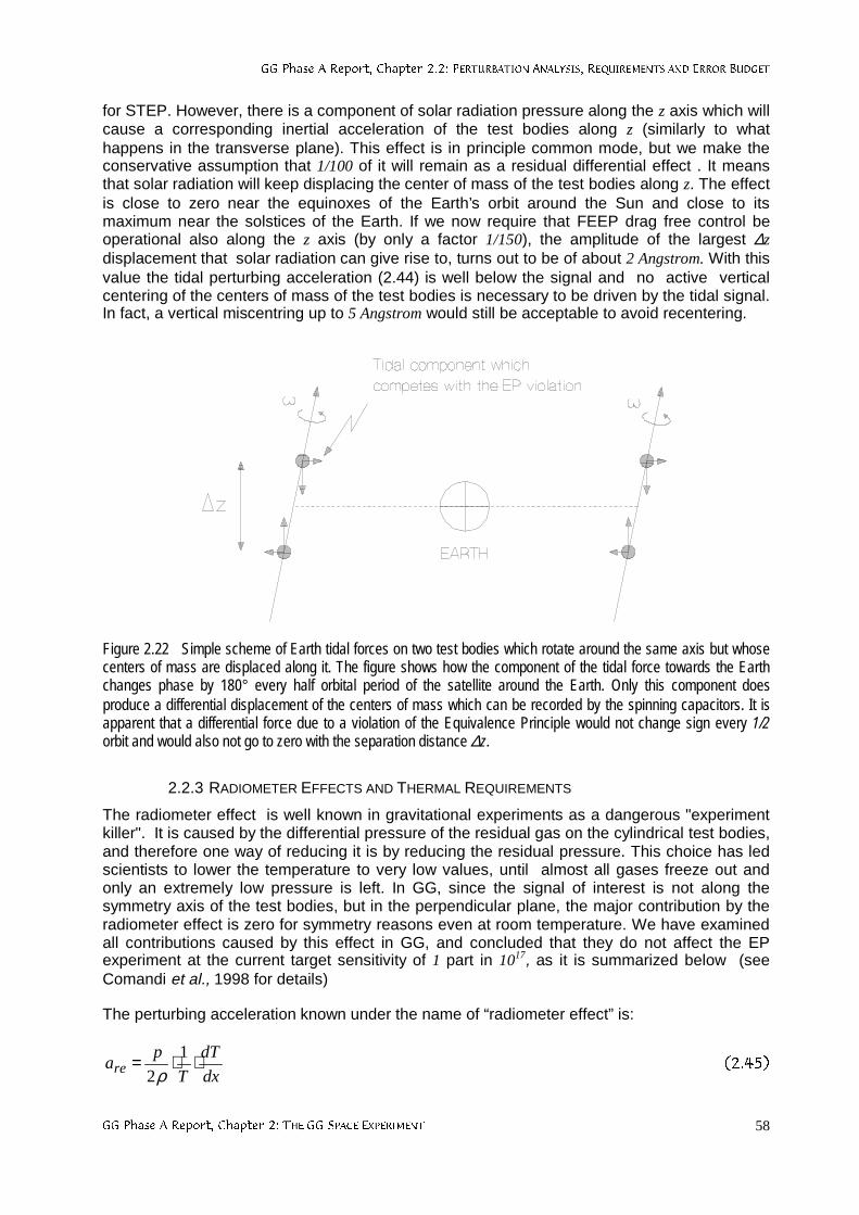
**3KDVH$5HSRUW&KDSWHU3(5785%$7,21$1$/<6,65(48,5(0(176$1'(5525%8'*(7
**3KDVH$5HSRUW&KDSWHU7+(**63$&((;3(5,0(17 58
for STEP. However, there is a component of solar radiation pressure along the z axis which willcause a corresponding inertial acceleration of the test bodies along z (similarly to whathappens in the transverse plane). This effect is in principle common mode, but we make theconservative assumption that 1/100 of it will remain as a residual differential effect . It meansthat solar radiation will keep displacing the center of mass of the test bodies along z. The effectis close to zero near the equinoxes of the Earth’s orbit around the Sun and close to itsmaximum near the solstices of the Earth. If we now require that FEEP drag free control beoperational also along the z axis (by only a factor 1/150), the amplitude of the largest ∆zdisplacement that solar radiation can give rise to, turns out to be of about 2 Angstrom. With thisvalue the tidal perturbing acceleration (2.44) is well below the signal and no active verticalcentering of the centers of mass of the test bodies is necessary to be driven by the tidal signal.In fact, a vertical miscentring up to 5 Angstrom would still be acceptable to avoid recentering.
Figure 2.22 Simple scheme of Earth tidal forces on two test bodies which rotate around the same axis but whosecenters of mass are displaced along it. The figure shows how the component of the tidal force towards the Earthchanges phase by 180° every half orbital period of the satellite around the Earth. Only this component doesproduce a differential displacement of the centers of mass which can be recorded by the spinning capacitors. It isapparent that a differential force due to a violation of the Equivalence Principle would not change sign every 1/2orbit and would also not go to zero with the separation distance ∆z.
2.2.3 RADIOMETER EFFECTS AND THERMAL REQUIREMENTS
The radiometer effect is well known in gravitational experiments as a dangerous "experimentkiller". It is caused by the differential pressure of the residual gas on the cylindrical test bodies,and therefore one way of reducing it is by reducing the residual pressure. This choice has ledscientists to lower the temperature to very low values, until almost all gases freeze out andonly an extremely low pressure is left. In GG, since the signal of interest is not along thesymmetry axis of the test bodies, but in the perpendicular plane, the major contribution by theradiometer effect is zero for symmetry reasons even at room temperature. We have examinedall contributions caused by this effect in GG, and concluded that they do not affect the EPexperiment at the current target sensitivity of 1 part in 1017, as it is summarized below (seeComandi et al., 1998 for details)
The perturbing acceleration known under the name of “radiometer effect” is:
dx
dT
T
pare ⋅⋅= 1
2ρ
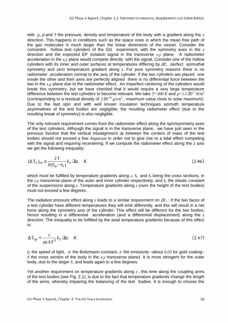
**3KDVH$5HSRUW&KDSWHU3(5785%$7,21$1$/<6,65(48,5(0(176$1'(5525%8'*(7
**3KDVH$5HSRUW&KDSWHU7+(**63$&((;3(5,0(17 59
with p, ρ and T the pressure, density and temperature of the body with a gradient along the xdirection. This happens in conditions such as the space ones in which the mean free path ofthe gas molecules is much larger than the linear dimension of the vessel. Consider theconcentric hollow test cylinders of the GG experiment, with the symmetry axes in the zdirection and the expected EP violation signal in the transverse x,y plane. A radiometeracceleration in the x,y plane would compete directly with the signal. Consider one of the hollowcylinders with its inner and outer surfaces at temperatures differing by ∆T, perfect azimuthalsymmetry and zero temperature gradient along z. For pure symmetry reasons there is noradiometer acceleration normal to the axis of the cylinder. If the two cylinders are placed oneinside the other and their axes are perfectly aligned there is no differential force between thetwo in the x,y plane due to the radiometer effect. An imperfect centering of the cylinders wouldbreak this symmetry, but we have checked that it would require a very large temperaturedifference between the test cylinders to become relevant. We take T=300 K and p=1.1⋅10-7 N/m2
(corresponding to a residual density of 2⋅10-16 g/cm3 ; maximum value close to solar maximum).Due to the fast spin and with well known insulation techniques azimuth temperatureasymmetries of the test bodies are negligible; the resulting radiometer effect (due to theresulting break of symmetry) is also negligible.
The only relevant requirement comes from the radiometer effect along the spin/symmetry axesof the test cylinders. Although the signal is in the transverse plane, we have just seen in theprevious Section that the vertical misalignment ∆z between the centers of mass of the testbodies should not exceed a few Angstrom in order not to give rise to a tidal effect competingwith the signal and requiring recentering. If we compute the radiometer effect along the z axiswe get the following inequality:
Kzkzio
re ∆⋅−
≤∆)SP(S
T2)T( z
which must be fulfilled by temperature gradients along z, So and Si being the cross sections, inthe x,y transverse plane of the outer and inner cylinder respectively, and kz the elastic constantof the suspensions along z. Temperature gradients along z (over the height of the test bodies)must not exceed a few degrees.
The radiation pressure effect along z leads to a similar requirement on ∆Tz : if the two faces ofa test cylinder have different temperatures they will emit differently, and this will result in a netforce along the symmetry axis of the cylinder. This effect will be different for the two bodies,hence resulting in a differential acceleration (and a differential displacement) along the zdirection. The inequality to be fulfilled by the axial temperature gradients because of this effectis:
Kzkrp ∆⋅<∆ z3ST
cT
σε
(c the speed of light, σ the Boltzmann constant, ε the emissivity −about 0.03 for gold coating−S the cross section of the body in the x,y transverse plane). It is more stringent for the outerbody, due to the larger S, and leads again to a few degrees.
Yet another requirement on temperature gradients along z , this time along the coupling armsof the test bodies (see Fig. 2.1), is due to the fact that temperature gradients change the lengthof the arms, whereby impairing the balancing of the test bodies. It is enough to choose the
**3KDVH$5HSRUW&KDSWHU3(5785%$7,21$1$/<6,65(48,5(0(176$1'(5525%8'*(7
**3KDVH$5HSRUW&KDSWHU7+(**63$&((;3(5,0(17 60
material for manufacturing the arms with a coefficient of thermal expansion of 10-5 /K ; then, iftemperature gradients along each arm do not exceed 1 K the balancing is not perturbed.
In this low equatorial orbit the GG satellite spends about 1/3 of its time in the shadow of theEarth and the rest in sunlight, thermal equilibrium temperatures in the two cases differing byseveral tens of degree. While azimuth temperature variations are inexistent because of the fastspin, temperature gradients between the illuminated and the dark side of the satellite whenexposed to radiation can in principle be very large. These gradients can be essentiallyeliminated inside a rapidly spinning spacecraft if it is properly insulated. Insulation and vacuumserve also the purpose of reducing the rate of temperature variation with time. For thetemperature stability in time inside the PGB laboratory at the level of the test bodies we requirethat:
dayKT /2.0≤& (2.48)
which, from thermal model simulations, turns out to be feasible by passive control only (seeSec. 4.4).
The temperature drift affects the stiffness of the suspensions, hence the balancing of the testbodies because the springs will not respond exactly the same to the same temperaturechanges. We require that the relative change in stiffness with temperature be of 1/4000 perdegree of temperature; experience with gravimeter springs for the measurement of Earth tideshas shown that it can be done much better (Melchior et al. 1979). If 1/100 of the stiffnessvariation is differential (which is reasonable because the test bodies springs are manufacturedto high precision, and can be tested in the laboratory), then there is a time interval of 20 daysbefore exceeding the required common mode rejection level (given by 2.38) whereby the testbodies need to be rebalanced.
If the test bodies expand uniformly (in azimuth), the relative position of their centers of massdoes not change; hence the signal will not change as long as the capacitance bridge remainsbalanced. However, the capacitance sensors will change their relative position in between thetest bodies to such an extent that the bridge may no longer be balanced. If this happens, acommon mode signal may become dominant over the expected differential signal. With therequirement (2.42) on bridge balancing this will take about 15 days. However, once thematerials for the test bodies have been selected (Be and Cu in the current baseline) and thebodies have been manufactured, thermal tests can be done so that the mounting arms of thecapacitance can be manufactured using a material whose coefficient of thermal expansionpartially compensates for the bridge unbalance caused by the thermal expansion of the testbodies. In this way the allowed time-span before mechanical rebalancing of the bridge wouldbecome longer than 2 weeks. Non uniform thermal expansion of the test bodies is small andgives a DC effect.
In summary, current temperature requirements (0.2 K/day stability in time at test masses level;1 K axial gradient over the test bodies and the coupling arms) appear to be doable with passivethermal insulation techniques (see Secs. 4.3 and 5.4); they allow 20 days of data taking beforerebalancing of the test bodies and at least 15 days (more if some more care is taken in themanufacture of the sensor plates arms) before rebalancing the read-out capacitance bridge.
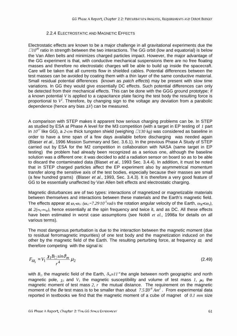
**3KDVH$5HSRUW&KDSWHU3(5785%$7,21$1$/<6,65(48,5(0(176$1'(5525%8'*(7
**3KDVH$5HSRUW&KDSWHU7+(**63$&((;3(5,0(17 61
2.2.4 ELECTROSTATIC AND MAGNETIC EFFECTS
Electrostatic effects are known to be a major challenge in all gravitational experiments due the≅ 1040 ratio in strength between the two interactions. The GG orbit (low and equatorial) is belowthe Van Allen belts and minimizes charged particles impact. However, the major advantage ofthe GG experiment is that, with conductive mechanical suspensions there are no free floatingmasses and therefore no electrostatic charges will be able to build up inside the spacecraft.Care will be taken that all currents flow in shielded cables. Potential differences between thetest masses can be avoided by coating them with a thin layer of the same conductive material.Small residual potential differences (known as patch effects) may be present with slow timevariations. In GG they would give essentially DC effects. Such potential differences can onlybe detected from their mechanical effects. This can be done with the GGG ground prototype; ifa known potential V is applied to a capacitance plate facing the test body the resulting force isproportional to V2. Therefore, by changing sign to the voltage any deviation from a parabolicdependence (hence any bias AV) can be measured.
A comparison with STEP makes it apparent how serious charging problems can be. In STEPas studied by ESA at Phase A level for the M3 competition (with a target in EP testing of 1 partin 1017 like GG), a 2-cm thick tungsten shield (weighing ≅ 130 kg) was considered as baseline inorder to have a time span of a few days available before discharging was needed again(Blaser et al., 1996 Mission Summary and Sec. 3.6.1). In the previous Phase A Study of STEPcarried out by ESA for the M2 competition in collaboration with NASA (same target in EPtesting) the problem had already been recognized as a serious one, although the baselinesolution was a different one: it was decided to add a radiation sensor on board so as to be ableto discard the contaminated data (Blaset et al., 1993 Sec. 3.4.4). In addition, it must be notedthat in STEP charged particles affect the EP experiment also by asymmetrical momentumtransfer along the sensitive axis of the test bodies, especially because their masses are small(a few hundred grams) (Blaser et al., 1993, Sec. 3.4.3). It is therefore a very good feature ofGG to be essentially unaffected by Van Allen belt effects and electrostatic charging.
Magnetic disturbances are of two types: interactions of magnetized or magnetizable materialsbetween themselves and interactions between these materials and the Earth’s magnetic field.The effects appear at gs-gË (gËp7.29¹10-5rad/s the rotation angular velocity of the Earth, gË gs),
at 2(gs-gË), hence essentially at the spin frequency and twice it, and as DC. All these effectshave been estimated in worst case assumptions (see Nobili et al., 1998a for details on allvarious terms).
The most dangerous perturbation is due to the interaction between the magnetic moment (dueto residual ferromagnetic impurities) of one test body and the magnetization induced on theother by the magnetic field of the Earth. The resulting perturbing force, at frequency ωs andtherefore competing with the signal is:
241
1 µϑχω
r
sinBVF m
s⊕≈ (2.49)
with BË the magnetic field of the Earth, hmp118 the angle between north geographic and northmagnetic pole, x1 and V1 the magnetic susceptibility and volume of test mass 1, m2 themagnetic moment of test mass 2, r the mutual distance. The requirement on the magneticmoment of the Be test mass is to be smaller than about 7.5⋅10-8 Am2 . From experimental datareported in textbooks we find that the magnetic moment of a cube of magnet of 0.1 mm size
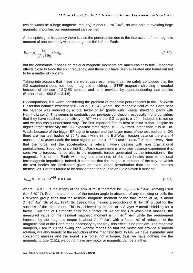
**3KDVH$5HSRUW&KDSWHU3(5785%$7,21$1$/<6,65(48,5(0(176$1'(5525%8'*(7
**3KDVH$5HSRUW&KDSWHU7+(**63$&((;3(5,0(17 62
(which would be a large magnetic impurity) is about 5⋅10-7 Am2 , so with care in avoiding largemagnetic impurities our requirement can be met.
At the spin/signal frequency there is also the perturbation due to the interaction of the magneticmoment of one test body with the magnetic field of the Earth:
msinhR
BF ϑµω )(2 +
≈′⊕
⊕ (2.50)
but the constraints it poses on residual magnetic moments are much easier to fulfill. Magneticeffects close to twice the spin frequency, and those DC have been evaluated and found out notto be a matter of concern.
Taking into account that these are worst case estimates, it can be safely concluded that theGG experiment does not need magnetic shielding. In STEP magnetic shielding is neededbecause of the use of SQUID sensors and its is provided by superconducting lead shields(Blaser et al., 1993 Sec.3.4.6).
By comparison, it is worth considering the problem of magnetic perturbations in the EÞt-WashEP torsion balance experiment (Su et al., 1994), where the magnetic field of the Earth nearthe balance was reduced by a total factor of 105 (partly with W-metal shielding, partly withHelmholtz coils). This seems to contradict our previous conclusion, especially if one considersthat they have reached a sensitivity R=10-12 while the GG target is R=10-17. Indeed, it is not soand we can easily understand why. The first important fact to bear in mind is that, despite itshigher target sensitivity the GG expected force signal is p 2.5 times larger than it is in EÞt-Wash, because of the bigger EP signal in space and the larger mass of the test bodies. In GGthere are two test bodies of 10 kg each while in the EÞt-Wash torsion balance there are 4masses of 10 grams each; the force signals are p 8.4.10-16 N and p 3.4.10-16 N respectively. Notethat the force, not the acceleration, is relevant when dealing with non gravitationalperturbations. Secondly, since the EÞt-Wash experiment is a torsion balance experiment it issensitive to torques, hence also to the magnetic torque generated by the interaction of themagnetic field of the Earth with magnetic moments of the test bodies (due to residualferromagnetic impurities). Indeed, it turns out that the magnetic moment of the tray on whichthe test bodies are positioned gives an even larger perturbation than the test massesthemselves. For this torque to be smaller than that due to an EP violation it must be:
NmBtray 03.0104.3 16 ⋅⋅< −⊕µ (2.51)
where p 0.03 m is the length of the arm. It must therefore be Wtray < 210-13Am2 (having usedBË= 510-5 T). From measurement of the torsion angle in absence of any shielding or coils theEÞt-Wash group finds that the residual magnetic moment of the tray (made of Al) is about2.410-8 Am2 (Su et al., 1994; Su 1992), thus making a reduction of BË by 105 crucial for thesuccess of the experiment. This is achieved by means of a 3-layer W-metal shielding for afactor 3,600 and of Helmholtz coils for a factor 28. As for the EÞt-Wash test masses, themeasured value of the residual magnetic moment is p 410-10 Am2 while the requirementimposed by the magnetic torque is about 710-9 Am2; with a factor 105 of reduction of themagnetic field of the Earth made necessary by the tray, this effect is no problem. The magneticdampers, used to kill the swing and wobble modes so that the motor can provide a smoothrotation, will also benefit of the reduction of the magnetic field. In GG we have symmetric andconcentric masses and the signal is a force, not a torque, thus we have nothing like themagnetic torque (2.51); we do not have any motor or magnetic dampers either.
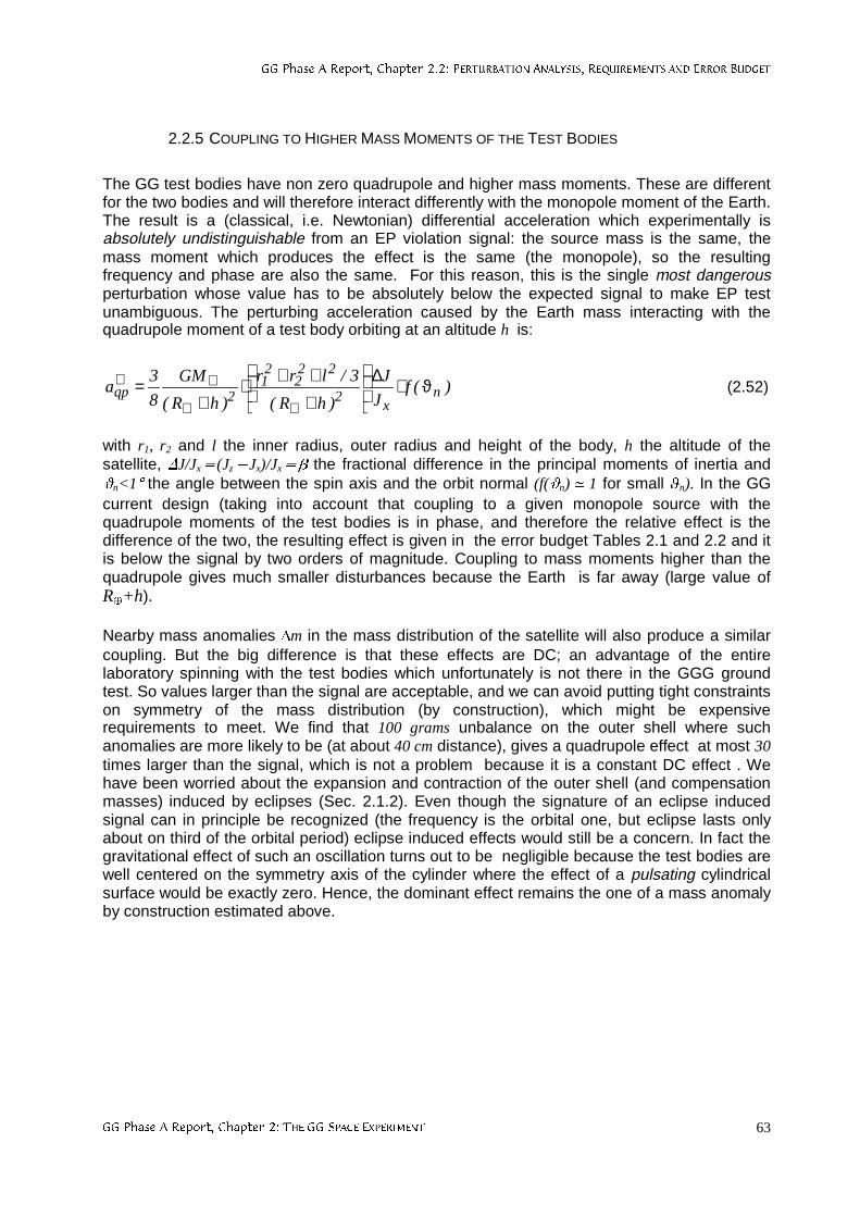
**3KDVH$5HSRUW&KDSWHU3(5785%$7,21$1$/<6,65(48,5(0(176$1'(5525%8'*(7
**3KDVH$5HSRUW&KDSWHU7+(**63$&((;3(5,0(17 63
2.2.5 COUPLING TO HIGHER MASS MOMENTS OF THE TEST BODIES
The GG test bodies have non zero quadrupole and higher mass moments. These are differentfor the two bodies and will therefore interact differently with the monopole moment of the Earth.The result is a (classical, i.e. Newtonian) differential acceleration which experimentally isabsolutely undistinguishable from an EP violation signal: the source mass is the same, themass moment which produces the effect is the same (the monopole), so the resultingfrequency and phase are also the same. For this reason, this is the single most dangerousperturbation whose value has to be absolutely below the expected signal to make EP testunambiguous. The perturbing acceleration caused by the Earth mass interacting with thequadrupole moment of a test body orbiting at an altitude h is:
)(fJ
J
)hR(
3/lrr
)hR(
GM
8
3a n
x2
222
21
2qp ϑ⋅∆
+++⋅
+=
⊕⊕
⊕⊕ (2.52)
with r1, r2 and l the inner radius, outer radius and height of the body, h the altitude of thesatellite, DJ/Jx5(Jz2Jx)/Jx5b the fractional difference in the principal moments of inertia andqn<18 the angle between the spin axis and the orbit normal (f(qn) p 1 for small hn). In the GGcurrent design (taking into account that coupling to a given monopole source with thequadrupole moments of the test bodies is in phase, and therefore the relative effect is thedifference of the two, the resulting effect is given in the error budget Tables 2.1 and 2.2 and itis below the signal by two orders of magnitude. Coupling to mass moments higher than thequadrupole gives much smaller disturbances because the Earth is far away (large value ofRË+h).
Nearby mass anomalies Am in the mass distribution of the satellite will also produce a similarcoupling. But the big difference is that these effects are DC; an advantage of the entirelaboratory spinning with the test bodies which unfortunately is not there in the GGG groundtest. So values larger than the signal are acceptable, and we can avoid putting tight constraintson symmetry of the mass distribution (by construction), which might be expensiverequirements to meet. We find that 100 grams unbalance on the outer shell where suchanomalies are more likely to be (at about 40 cm distance), gives a quadrupole effect at most 30times larger than the signal, which is not a problem because it is a constant DC effect . Wehave been worried about the expansion and contraction of the outer shell (and compensationmasses) induced by eclipses (Sec. 2.1.2). Even though the signature of an eclipse inducedsignal can in principle be recognized (the frequency is the orbital one, but eclipse lasts onlyabout on third of the orbital period) eclipse induced effects would still be a concern. In fact thegravitational effect of such an oscillation turns out to be negligible because the test bodies arewell centered on the symmetry axis of the cylinder where the effect of a pulsating cylindricalsurface would be exactly zero. Hence, the dominant effect remains the one of a mass anomalyby construction estimated above.
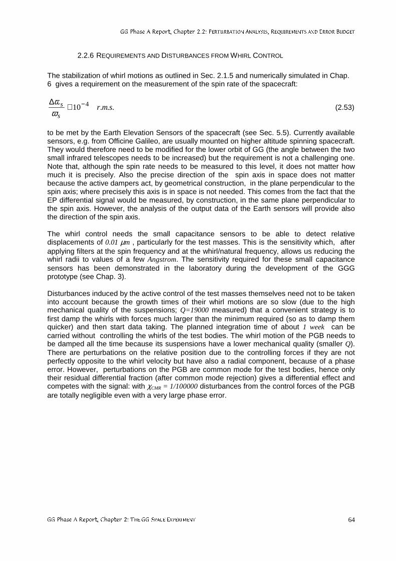
**3KDVH$5HSRUW&KDSWHU3(5785%$7,21$1$/<6,65(48,5(0(176$1'(5525%8'*(7
**3KDVH$5HSRUW&KDSWHU7+(**63$&((;3(5,0(17 64
2.2.6 REQUIREMENTS AND DISTURBANCES FROM WHIRL CONTROL
The stabilization of whirl motions as outlined in Sec. 2.1.5 and numerically simulated in Chap.6 gives a requirement on the measurement of the spin rate of the spacecraft:
...10 4 smrs
s −≅∆ωω
(2.53)
to be met by the Earth Elevation Sensors of the spacecraft (see Sec. 5.5). Currently availablesensors, e.g. from Officine Galileo, are usually mounted on higher altitude spinning spacecraft.They would therefore need to be modified for the lower orbit of GG (the angle between the twosmall infrared telescopes needs to be increased) but the requirement is not a challenging one.Note that, although the spin rate needs to be measured to this level, it does not matter howmuch it is precisely. Also the precise direction of the spin axis in space does not matterbecause the active dampers act, by geometrical construction, in the plane perpendicular to thespin axis; where precisely this axis is in space is not needed. This comes from the fact that theEP differential signal would be measured, by construction, in the same plane perpendicular tothe spin axis. However, the analysis of the output data of the Earth sensors will provide alsothe direction of the spin axis.
The whirl control needs the small capacitance sensors to be able to detect relativedisplacements of 0.01 µm , particularly for the test masses. This is the sensitivity which, afterapplying filters at the spin frequency and at the whirl/natural frequency, allows us reducing thewhirl radii to values of a few Angstrom. The sensitivity required for these small capacitancesensors has been demonstrated in the laboratory during the development of the GGGprototype (see Chap. 3).
Disturbances induced by the active control of the test masses themselves need not to be takeninto account because the growth times of their whirl motions are so slow (due to the highmechanical quality of the suspensions; Q=19000 measured) that a convenient strategy is tofirst damp the whirls with forces much larger than the minimum required (so as to damp themquicker) and then start data taking. The planned integration time of about 1 week can becarried without controlling the whirls of the test bodies. The whirl motion of the PGB needs tobe damped all the time because its suspensions have a lower mechanical quality (smaller Q).There are perturbations on the relative position due to the controlling forces if they are notperfectly opposite to the whirl velocity but have also a radial component, because of a phaseerror. However, perturbations on the PGB are common mode for the test bodies, hence onlytheir residual differential fraction (after common mode rejection) gives a differential effect andcompetes with the signal: with χCMR = 1/100000 disturbances from the control forces of the PGBare totally negligible even with a very large phase error.
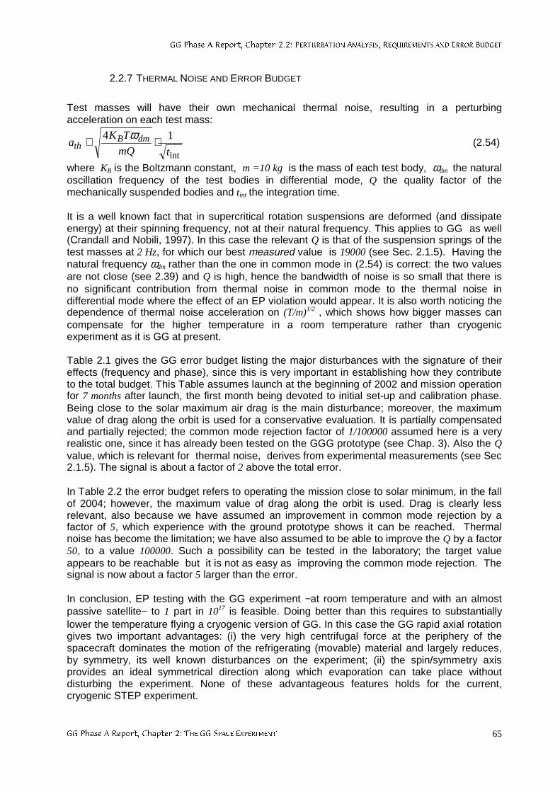
**3KDVH$5HSRUW&KDSWHU3(5785%$7,21$1$/<6,65(48,5(0(176$1'(5525%8'*(7
**3KDVH$5HSRUW&KDSWHU7+(**63$&((;3(5,0(17 65
2.2.7 THERMAL NOISE AND ERROR BUDGET
Test masses will have their own mechanical thermal noise, resulting in a perturbingacceleration on each test mass:
int
14
tmQ
TKa dmB
th ⋅≅ ω (2.54)
where KB is the Boltzmann constant, m =10 kg is the mass of each test body, ωdm the naturaloscillation frequency of the test bodies in differential mode, Q the quality factor of themechanically suspended bodies and tint the integration time.
It is a well known fact that in supercritical rotation suspensions are deformed (and dissipateenergy) at their spinning frequency, not at their natural frequency. This applies to GG as well(Crandall and Nobili, 1997). In this case the relevant Q is that of the suspension springs of thetest masses at 2 Hz, for which our best measured value is 19000 (see Sec. 2.1.5). Having thenatural frequency ωdm rather than the one in common mode in (2.54) is correct: the two valuesare not close (see 2.39) and Q is high, hence the bandwidth of noise is so small that there isno significant contribution from thermal noise in common mode to the thermal noise indifferential mode where the effect of an EP violation would appear. It is also worth noticing thedependence of thermal noise acceleration on (T/m)1/2 , which shows how bigger masses cancompensate for the higher temperature in a room temperature rather than cryogenicexperiment as it is GG at present.
Table 2.1 gives the GG error budget listing the major disturbances with the signature of theireffects (frequency and phase), since this is very important in establishing how they contributeto the total budget. This Table assumes launch at the beginning of 2002 and mission operationfor 7 months after launch, the first month being devoted to initial set-up and calibration phase.Being close to the solar maximum air drag is the main disturbance; moreover, the maximumvalue of drag along the orbit is used for a conservative evaluation. It is partially compensatedand partially rejected; the common mode rejection factor of 1/100000 assumed here is a veryrealistic one, since it has already been tested on the GGG prototype (see Chap. 3). Also the Qvalue, which is relevant for thermal noise, derives from experimental measurements (see Sec2.1.5). The signal is about a factor of 2 above the total error.
In Table 2.2 the error budget refers to operating the mission close to solar minimum, in the fallof 2004; however, the maximum value of drag along the orbit is used. Drag is clearly lessrelevant, also because we have assumed an improvement in common mode rejection by afactor of 5, which experience with the ground prototype shows it can be reached. Thermalnoise has become the limitation; we have also assumed to be able to improve the Q by a factor50, to a value 100000. Such a possibility can be tested in the laboratory; the target valueappears to be reachable but it is not as easy as improving the common mode rejection. Thesignal is now about a factor 5 larger than the error.
In conclusion, EP testing with the GG experiment −at room temperature and with an almostpassive satellite− to 1 part in 1017 is feasible. Doing better than this requires to substantiallylower the temperature flying a cryogenic version of GG. In this case the GG rapid axial rotationgives two important advantages: (i) the very high centrifugal force at the periphery of thespacecraft dominates the motion of the refrigerating (movable) material and largely reduces,by symmetry, its well known disturbances on the experiment; (ii) the spin/symmetry axisprovides an ideal symmetrical direction along which evaporation can take place withoutdisturbing the experiment. None of these advantageous features holds for the current,cryogenic STEP experiment.
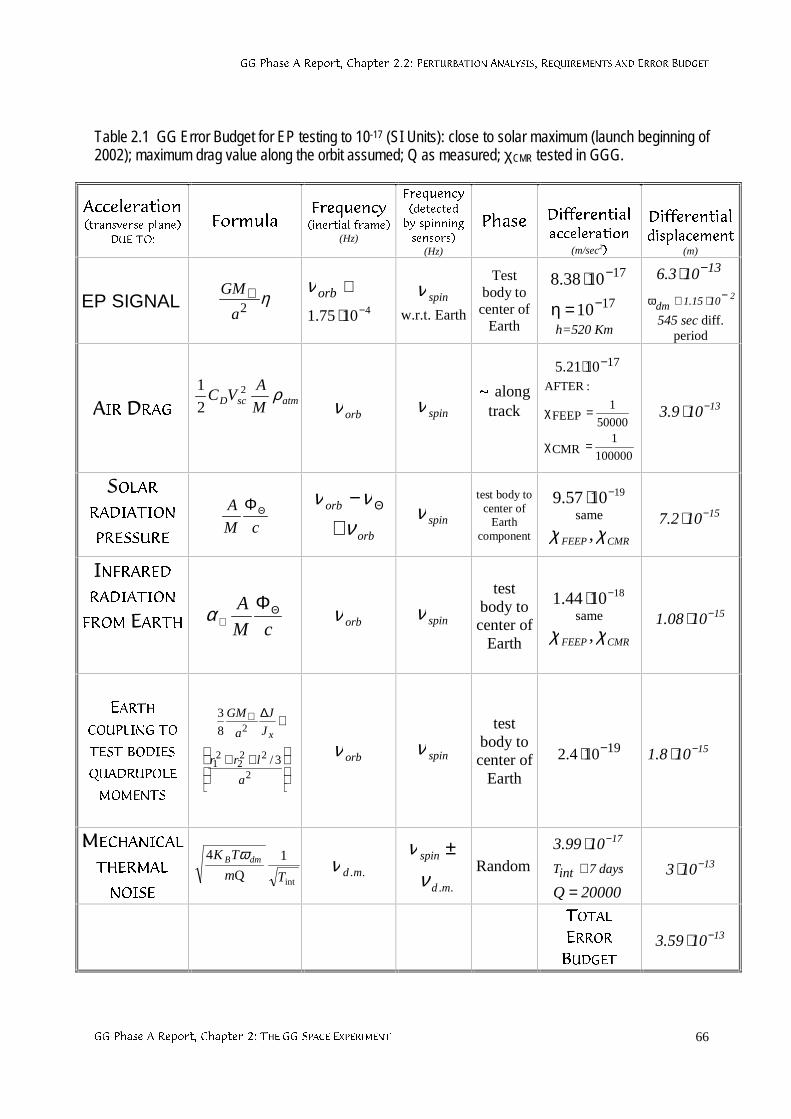
**3KDVH$5HSRUW&KDSWHU3(5785%$7,21$1$/<6,65(48,5(0(176$1'(5525%8'*(7
**3KDVH$5HSRUW&KDSWHU7+(**63$&((;3(5,0(17 66
Table 2.1 GG Error Budget for EP testing to 10-17 (SI Units): close to solar maximum (launch beginning of2002); maximum drag value along the orbit assumed; Q as measured; χCMR tested in GGG.
$FFHOHUDWLRQWUDQVYHUVHSODQH
'8(72
)RUPXOD)UHTXHQF\LQHUWLDOIUDPH
(Hz)
)UHTXHQF\GHWHFWHGE\VSLQQLQJVHQVRUV
(Hz)
3KDVH 'LIIHUHQWLDODFFHOHUDWLRQ
(m/sec2
'LIIHUHQWLDOGLVSODFHPHQW
(m)
EP SIGNAL η2a
GM⊕41075.1 −⋅
≅orbνspinν
w.r.t. Earth
Testbody tocenter of
Earth
17
17
10
1038.8−
−
=η
⋅
h=520 Km
13103.6 −⋅21015.1dm
−⋅≅ω
545 sec diff.period
$,5'5$*atmscD M
AVC ρ2
2
1
orbν spinνaalong
track
100000
1CMR
50000
1FEEP
:AFTER
171021.5
=χ
=χ
−⋅
13109.3 −⋅
62/$55$',$7,21
35(6685(cM
A ΘΦ
orb
orb
ννν
≅− Θ
spinνtest body to
center ofEarth
component
191057.9 −⋅same
CMRFEEP χχ ,15102.7 −⋅
,1)5$5('5$',$7,21
)520($57+ cM
A Θ⊕
Φα orbν spinνtest
body tocenter of
Earth
181044.1 −⋅same
CMRFEEP χχ ,151008.1 −⋅
($57+&283/,1*72
7(67%2',(6
48$'5832/(
020(176
++
⋅∆⊕
2
222
21
2
3/
8
3
a
lrr
J
J
a
GM
x
orbν spinνtest
body tocenter of
Earth
19104.2 −⋅ 15108.1 −⋅
0(&+$1,&$/
7+(50$/
12,6(int
1
Q
4
Tm
TK dmB ω..mdν
..md
spin
νν ±
Random
20000Q
1099.3
days7intT
17
=
⋅≅
−
13103 −⋅
727$/(5525%8'*(7
131059.3 −⋅
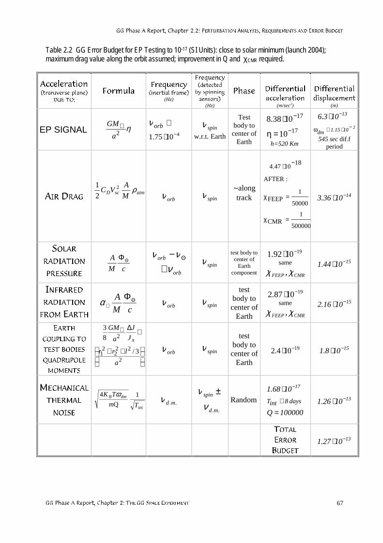
**3KDVH$5HSRUW&KDSWHU3(5785%$7,21$1$/<6,65(48,5(0(176$1'(5525%8'*(7
**3KDVH$5HSRUW&KDSWHU7+(**63$&((;3(5,0(17 67
Table 2.2 GG Error Budget for EP Testing to 10-17 (SI Units): close to solar minimum (launch 2004);maximum drag value along the orbit assumed; improvement in Q and χCMR required.
$FFHOHUDWLRQWUDQVYHUVHSODQH
'8(72
)RUPXOD)UHTXHQF\LQHUWLDOIUDPH
(Hz)
)UHTXHQF\GHWHFWHGE\VSLQQLQJVHQVRUV
(Hz)
3KDVH 'LIIHUHQWLDODFFHOHUDWLRQ
(m/sec2)
'LIIHUHQWLDOGLVSODFHPHQW
(m)
EP SIGNAL η2a
GM⊕41075.1 −⋅
≅orbνspinν
w.r.t. Earth
Testbody tocenter of
Earth
17
17
10
1038.8−
−
=η
⋅
h=520 Km
13103.6 −⋅21015.1dm
−⋅≅ω
545 sec dif.fperiod
$,5'5$*atmscD M
AVC ρ2
2
1
orbν spinνaalongtrack
500000
1CMR
50000
1FEEP
:AFTER
181047.4
=χ
=χ
−⋅
141036.3 −⋅
62/$55$',$7,21
35(6685(cM
A ΘΦ
orb
orb
ννν
≅− Θ
spinνtest body to
center ofEarth
component
191092.1 −⋅same
CMRFEEP χχ ,151044.1 −⋅
,1)5$5('5$',$7,21
)520($57+ cM
A Θ⊕
Φα orbν spinνtest
body tocenter of
Earth
191087.2 −⋅same
CMRFEEP χχ ,151016.2 −⋅
($57+&283/,1*72
7(67%2',(6
48$'5832/(
020(176
++
⋅∆⊕
2
222
21
2
3/
8
3
a
lrr
J
J
a
GM
x
orbν spinνtest
body tocenter of
Earth
19104.2 −⋅ 15108.1 −⋅
0(&+$1,&$/
7+(50$/
12,6(int
1
Q
4
Tm
TK dmB ω..mdν
..md
spin
νν ±
Random
100000Q
1068.1
days8intT
17
=
⋅≅
−
131026.1 −⋅
727$/(5525%8'*(7
131027.1 −⋅
**3KDVH$5HSRUW&KDSWHU 68
3. THE GG PAYLOAD PROTOTYPE ON THE GROUND (GGG)
3.1 THE GOALS
"GALILEO GALILEI ON THE GROUND" (GGG) is an experiment to test the Equivalence Principlewith an apparatus very similar to a prototype of the payload designed for the GG spaceexperiment. The experiment is carried out in the laboratories of LABEN in Florence; it has beendesigned by the GG scientists at the University of Pisa and is under the responsibility of Dr D.Bramanti. The scientific goal is to test the Equivalence Principle to 1 part in 1013, which wouldimprove the accuracy of current laboratory tests by an order of magnitude. Since the apparatusused is a prototype of the space payload, GGG can validate the proposed space mission andbe a valuable experiment in its own right. In turn, the design of the space experiment doessubstantially benefit from experience gained in the laboratory, as it has already happened.
3.2 SIMILARITIES AND DIFFERENCES WITH THE GG SPACE EXPERIMENT
If two test bodies of different composition orbit around the Earth at an altitude h the EPviolation signal at level η of the Eötvös adimensional parameter driven by the Earth as asource mass is given by Eq. (1.2). For h=520 km, it amounts to: aEP ≅ 8.4⋅η m/sec2 . Theexperiment is made by comparing the equilibrium positions of the bodies under thegravitational attraction from the Earth (proportional to the gravitational mass of the body), andthe centrifugal force due to their orbital motion around the Earth (proportional to the inertialmass of the body). If the test bodies are coaxial cylinders the displacement vector resultingfrom an EP violation is always directed to the center of the Earth (see Fig. 1.1). Instead, if thebodies are suspended on the ground each of them reaches equilibrium when the componenton the horizontal plane of the centrifugal force due to the diurnal rotation of the Earth isbalanced by the horizontal component of the local gravitational attraction. This is theequilibrium position of an ordinary plumb line, which does not point to the center of the Earthbecause of the centrifugal force due to the rotation of the Earth, but it is displaced alwaysalong the North-South direction. Therefore, the EP violation signal (with the Earth as thesource mass) is:
cossinRa 2EP ⋅θ≅ ⊕⊕⊕ (3.1)
where S is the latitude of the laboratory and gË is the diurnal angular velocity of the Earth; themaximum value of (3.1) is at 45° latitude ad amounts to 1.69⋅10-2 m/sec2 , about 500 timessmaller than in space. Being the displacement fixed in the North-South direction there is nomodulation of the effect. If instead one takes the Sun as the driving source mass, theequilibrium of the suspended body is between the gravitational attraction from the Sun and thecentrifugal force due to the annual rotation around it. The resulting signal is, at most:
232sunsun
EP sec/m106D
GMa −⋅≅≤ (3.2)
(D is the Earth-Sun distance and Msun the mass of the Sun); its intensity is modulated by thediurnal rotation of the Earth from a minimum value depending on the latitude (as sinS) and themaximum given by (3.2). If the ground experiment is carried out with the Earth as a source,the signal in space given by Eq. (1.2) is 500 times stronger; if the ground experiment uses theSun as a source in order to provide a diurnal modulation, then the signal in space (still with theEarth as a source) is at least 1400 times stronger. Note that a space experiment with the Sunas a source has no advantage over the ground ones.
**3KDVH$5HSRUW&KDSWHU7+(**3$</2$'352727<3(217+(*5281'***
**3KDVH$5HSRUW&KDSWHU 69
In the GGG experiment the EP violation signal, constant in time and fixed in direction in thehorizontal plane, is modulated at the spinning frequency with the spin axis in the verticaldirection, similarly to GG. The spin frequency can be higher than 2 Hz (10 Hz reached so far)but the mechanical coupling of the test bodies cannot be as weak as in space; the apparatus issomewhat different because of local gravity but, it is based on the same dynamical principle(see Sec. 3.3)
Whirl motions can be damped both passively and actively, and active damping can be bothrotating and non rotating (GG needs active rotating damping, as discussed in Sec. 2.1.5 and inChap. 6). GGG needs no drag compensation because there is no drag; instead, there isseismic noise which −similarly to air drag− is in principle common mode. It is partially rejectedby balancing the test bodies and partially attenuated. The read-out capacitance system is inall similar to the GG read-out and it can reach, in terms of displacement measurements, thesame sensitivity as it is required for GG.
In GG the whole spacecraft spins with the test masses, which makes perturbations from alllocal mass anomalies DC (see Sec. 2.2.5); this is not the case on the ground. The effect is lesssevere than in torsion balances because the test cylinders are very well centered on oneanother. In any case it can be taken care of, similarly to how it is done in torsion balanceexperiments (Sue et al., 1994), i. e. by using test masses specially designed to amplify theperturbations from local anomalies and then compensate for them with appropriate nearbymasses. Effects on the spin axes of the test cylinders are also different in GGG as comparedto GG because the GGG test bodies are not suspended from their center mass. Thegravitational torque caused by the local acceleration of gravity, and the torque due to the factthat the laboratory is rotating with the Earth (hence it is not an inertial system), affect theequilibrium position of the coupled test bodies. These effects have been the subject oftheoretical analysis and numerical simulation, and are to be compared with the experimentalresults (Comandi, 1998). In GG the test cylinders are suspended from their centers of massand the spin axis is subject only to a slow precession (see Sec. 2.1.2).
**3KDVH$5HSRUW&KDSWHU7+(**3$</2$'352727<3(217+(*5281'***
**3KDVH$5HSRUW&KDSWHU 70
3.3 THE CONCEPTUAL DESIGN
The GGG experiment set up is made of two test bodies (in the shape of coaxial cylinders) in acoupled mechanical suspension (as shown in Fig. 3.1). In between the test cylinders areplaced capacitance sensors forming a bridge to measure displacements of the test cylindersrelative to one another in the horizontal plane. A motor sets the whole system in rotation alonga vertical axis. The laminar suspensions shown in Fig. 3.3 are designed to withstand the localforce of gravity along the vertical while being very weak in response to any force in thehorizontal plane.
In more detail, with reference to Fig 3.1, the system can be described as follows. It is made of4 rotors. One is the suspension tube, held by a shaft turning inside ball bearings; rotation istransmitted from the motor (in violet on the left) to the central shaft by means of 2 O-rings (notshown in this Figure) on pulleys. The 2 test cylinders are shown in green (the inner one) andblue (the outer one). They are suspended by means of 2 laminar suspensions (in red; seepicture in Fig. 3.3) from the top (the blue cylinder) and the bottom (the green cylinder) of acoupling arm (the fourth rotor of the system). The coupling arm is in its turn suspended, at itscenter, from the center of the suspension tube. The suspension point of the coupling arm canbe finely adjusted along the vertical; the zero position of the whole pendulum (made of thecoupled system of test bodies) and the period of the differential oscillations of the two bodiesof the pendulum can be finely adjusted mechanically by means of appropriate rings andscrews of small mass. The capacitance plates of the read-out are shown in between the testmasses. The two rings (in yellow) mounted on the suspension tube contain the 2 capacitancebridges, their preamplifiers, the signal demodulators, the A/D (analog-to-digital) converters andthe driver of the optical emitter, which is located at the very top of the rotating shaft (in order totransmit the demodulated signal from the rotor to the non rotating frame and then outside ofthe vacuum chamber). At the top of the shaft there are 2 sliding contacts for powertransmission to the electronics of the rotor through a stabilized power supply (in yellow on adish on top of the rotor). To this dish is also attached a simple optical device which provides areference signal for the phase of the rotor. The passive damper (see Fig. 3.8) is shown underthe lowest laminar suspension and it is obviously not rotating. The two verticals crews (in lightblue) allow us, by means of a chain at the top (shown in Fig. 3.6) to move a platform up anddown holding the test cylinders during the assembling phase. The non rotating frame and thevacuum chamber are drawn in gray.
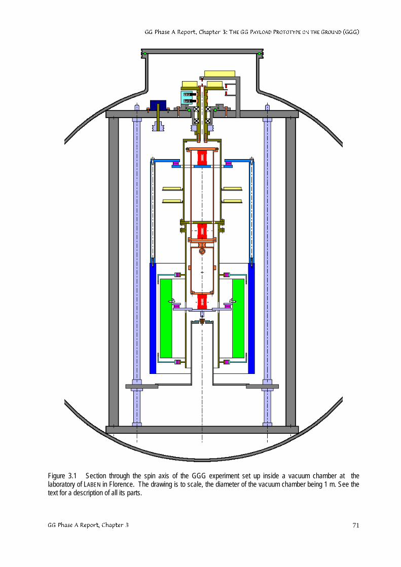
**3KDVH$5HSRUW&KDSWHU7+(**3$</2$'352727<3(217+(*5281'***
**3KDVH$5HSRUW&KDSWHU 71
Figure 3.1 Section through the spin axis of the GGG experiment set up inside a vacuum chamber at thelaboratory of LABEN in Florence. The drawing is to scale, the diameter of the vacuum chamber being 1 m. See thetext for a description of all its parts.
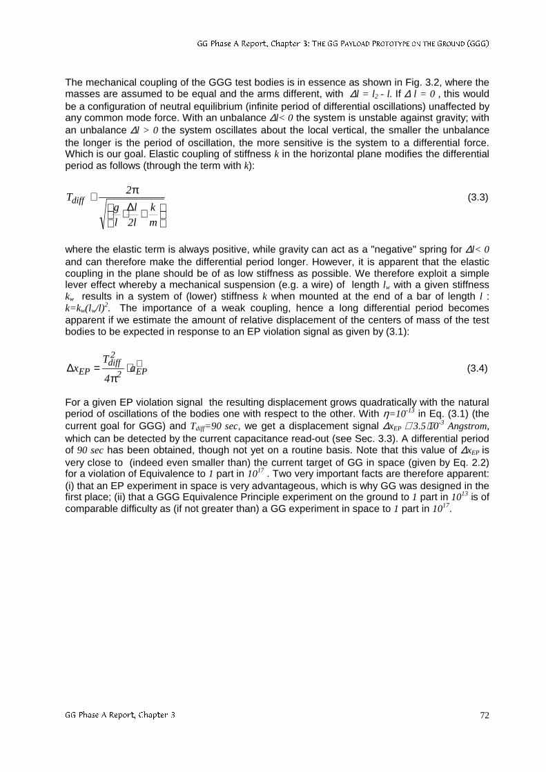
**3KDVH$5HSRUW&KDSWHU7+(**3$</2$'352727<3(217+(*5281'***
**3KDVH$5HSRUW&KDSWHU 72
The mechanical coupling of the GGG test bodies is in essence as shown in Fig. 3.2, where themasses are assumed to be equal and the arms different, with ∆l = l2 - l. If ∆ l = 0 , this wouldbe a configuration of neutral equilibrium (infinite period of differential oscillations) unaffected byany common mode force. With an unbalance ∆l< 0 the system is unstable against gravity; withan unbalance ∆l > 0 the system oscillates about the local vertical, the smaller the unbalancethe longer is the period of oscillation, the more sensitive is the system to a differential force.Which is our goal. Elastic coupling of stiffness k in the horizontal plane modifies the differentialperiod as follows (through the term with k):
+∆⋅
π≅
m
k
l2
l
l
g
2Tdiff (3.3)
where the elastic term is always positive, while gravity can act as a "negative" spring for ∆l< 0and can therefore make the differential period longer. However, it is apparent that the elasticcoupling in the plane should be of as low stiffness as possible. We therefore exploit a simplelever effect whereby a mechanical suspension (e.g. a wire) of length lw with a given stiffnesskw results in a system of (lower) stiffness k when mounted at the end of a bar of length l :k=kw(lw/l)2. The importance of a weak coupling, hence a long differential period becomesapparent if we estimate the amount of relative displacement of the centers of mass of the testbodies to be expected in response to an EP violation signal as given by (3.1):
⊕⋅π
=∆ EP2
2diff
EP a4
Tx (3.4)
For a given EP violation signal the resulting displacement grows quadratically with the naturalperiod of oscillations of the bodies one with respect to the other. With η=10-13 in Eq. (3.1) (thecurrent goal for GGG) and Tdiff=90 sec, we get a displacement signal ∆xEP ≅ 3.5⋅10-3 Angstrom,which can be detected by the current capacitance read-out (see Sec. 3.3). A differential periodof 90 sec has been obtained, though not yet on a routine basis. Note that this value of ∆xEP isvery close to (indeed even smaller than) the current target of GG in space (given by Eq. 2.2)for a violation of Equivalence to 1 part in 1017 . Two very important facts are therefore apparent:(i) that an EP experiment in space is very advantageous, which is why GG was designed in thefirst place; (ii) that a GGG Equivalence Principle experiment on the ground to 1 part in 1013 is ofcomparable difficulty as (if not greater than) a GG experiment in space to 1 part in 1017.
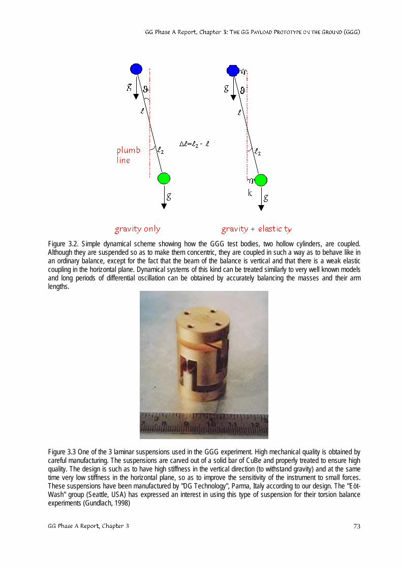
**3KDVH$5HSRUW&KDSWHU7+(**3$</2$'352727<3(217+(*5281'***
**3KDVH$5HSRUW&KDSWHU 73
Figure 3.2. Simple dynamical scheme showing how the GGG test bodies, two hollow cylinders, are coupled.Although they are suspended so as to make them concentric, they are coupled in such a way as to behave like inan ordinary balance, except for the fact that the beam of the balance is vertical and that there is a weak elasticcoupling in the horizontal plane. Dynamical systems of this kind can be treated similarly to very well known modelsand long periods of differential oscillation can be obtained by accurately balancing the masses and their armlengths.
Figure 3.3 One of the 3 laminar suspensions used in the GGG experiment. High mechanical quality is obtained bycareful manufacturing. The suspensions are carved out of a solid bar of CuBe and properly treated to ensure highquality. The design is such as to have high stiffness in the vertical direction (to withstand gravity) and at the sametime very low stiffness in the horizontal plane, so as to improve the sensitivity of the instrument to small forces.These suspensions have been manufactured by "DG Technology", Parma, Italy according to our design. The "Eöt-Wash" group (Seattle, USA) has expressed an interest in using this type of suspension for their torsion balanceexperiments (Gundlach, 1998)
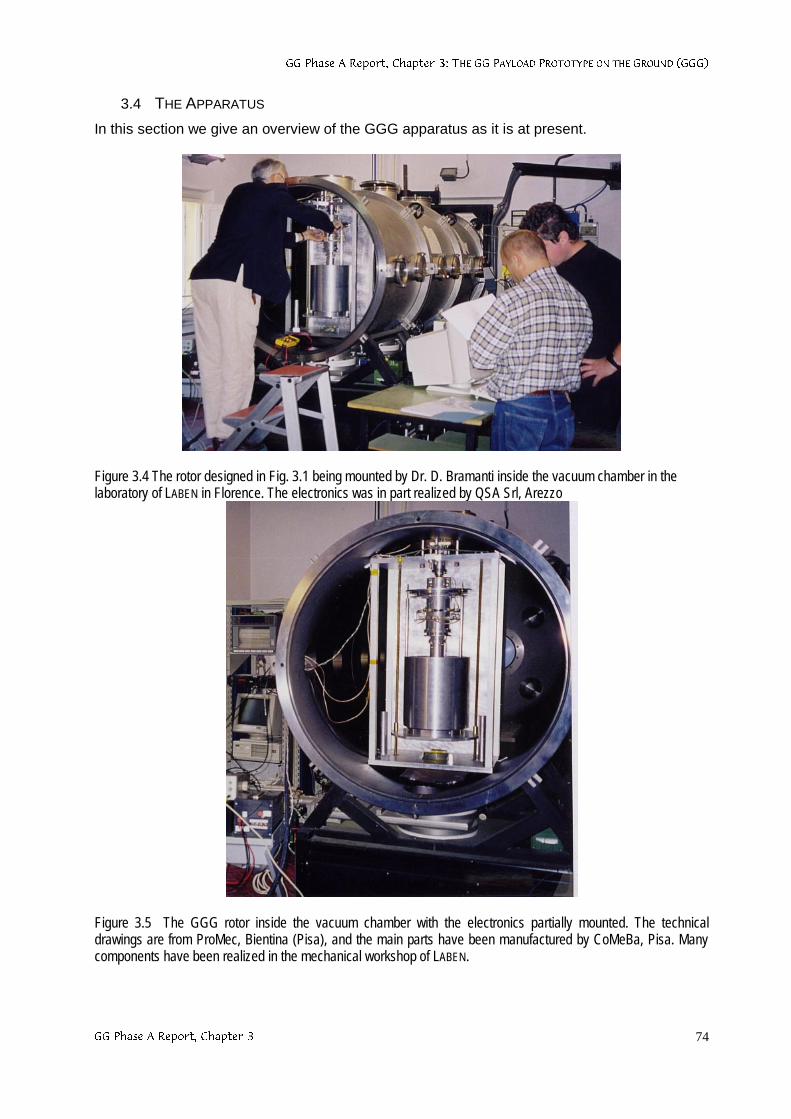
**3KDVH$5HSRUW&KDSWHU7+(**3$</2$'352727<3(217+(*5281'***
**3KDVH$5HSRUW&KDSWHU 74
3.4 THE APPARATUS
In this section we give an overview of the GGG apparatus as it is at present.
Figure 3.4 The rotor designed in Fig. 3.1 being mounted by Dr. D. Bramanti inside the vacuum chamber in thelaboratory of LABEN in Florence. The electronics was in part realized by QSA Srl, Arezzo
Figure 3.5 The GGG rotor inside the vacuum chamber with the electronics partially mounted. The technicaldrawings are from ProMec, Bientina (Pisa), and the main parts have been manufactured by CoMeBa, Pisa. Manycomponents have been realized in the mechanical workshop of LABEN.
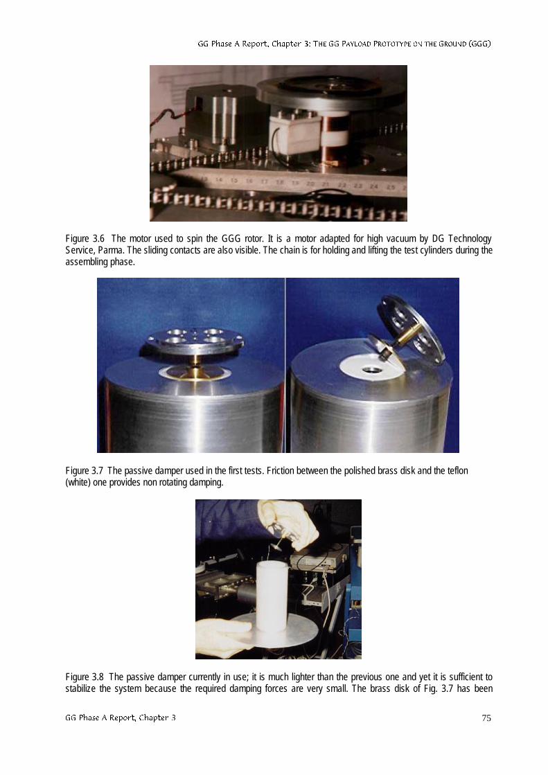
**3KDVH$5HSRUW&KDSWHU7+(**3$</2$'352727<3(217+(*5281'***
**3KDVH$5HSRUW&KDSWHU 75
Figure 3.6 The motor used to spin the GGG rotor. It is a motor adapted for high vacuum by DG TechnologyService, Parma. The sliding contacts are also visible. The chain is for holding and lifting the test cylinders during theassembling phase.
Figure 3.7 The passive damper used in the first tests. Friction between the polished brass disk and the teflon(white) one provides non rotating damping.
Figure 3.8 The passive damper currently in use; it is much lighter than the previous one and yet it is sufficient tostabilize the system because the required damping forces are very small. The brass disk of Fig. 3.7 has been
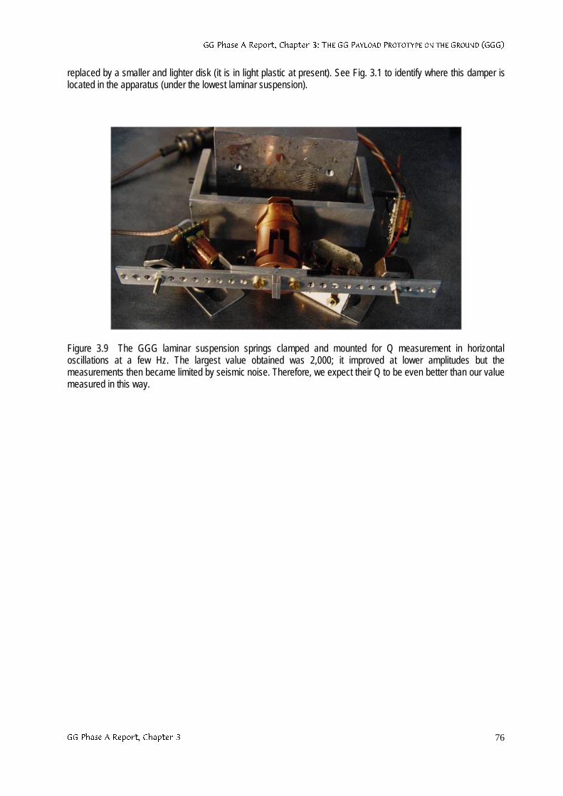
**3KDVH$5HSRUW&KDSWHU7+(**3$</2$'352727<3(217+(*5281'***
**3KDVH$5HSRUW&KDSWHU 76
replaced by a smaller and lighter disk (it is in light plastic at present). See Fig. 3.1 to identify where this damper islocated in the apparatus (under the lowest laminar suspension).
Figure 3.9 The GGG laminar suspension springs clamped and mounted for Q measurement in horizontaloscillations at a few Hz. The largest value obtained was 2,000; it improved at lower amplitudes but themeasurements then became limited by seismic noise. Therefore, we expect their Q to be even better than our valuemeasured in this way.
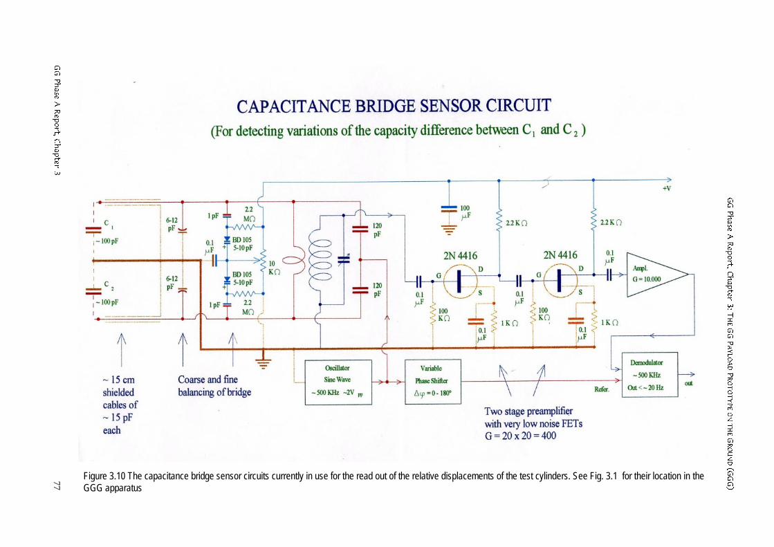
**3K
DVH$5HS
RUW&KDS
WHU7
+(*
*3$</2
$'352727<3(2
17+(*
5281'*
**
**3K
DVH$5HS
RUW&
KDS
WHU77
Figure 3.10 The capacitance bridge sensor circuits currently in use for the read out of the relative displacements of the test cylinders. See Fig. 3.1 for their location in theGGG apparatus
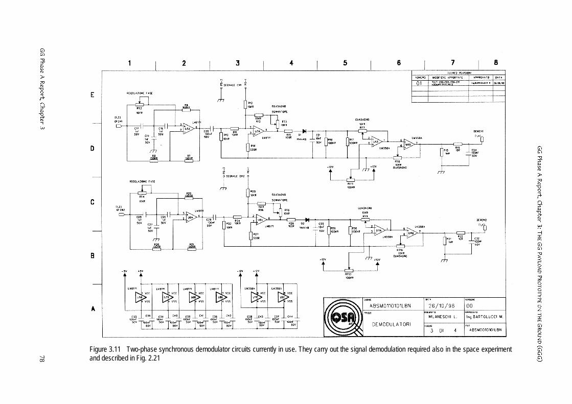
**3K
DVH$5HS
RUW&KDS
WHU7
+(*
*3$</2
$'352727<3(2
17+(*
5281'*
**
**3K
DVH$5HS
RUW&
KDS
WHU78
Figure 3.11 Two-phase synchronous demodulator circuits currently in use. They carry out the signal demodulation required also in the space experimentand described in Fig. 2.21
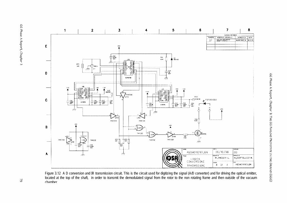
**3K
DVH$5HS
RUW&KDS
WHU7
+(*
*3$</2
$'352727<3(2
17+(*
5281'*
**
**3K
DVH$5HS
RUW&
KDS
WHU79
Figure 3.12 A D conversion and IR transmission circuit. This is the circuit used for digitizing the signal (A/D converter) and for driving the optical emitter,located at the top of the shaft, in order to transmit the demodulated signal from the rotor to the non rotating frame and then outside of the vacuumchamber.
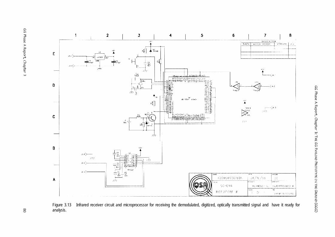
**3K
DVH$5HS
RUW&KDS
WHU7
+(*
*3$</2
$'352727<3(2
17+(*
5281'*
**
**3K
DVH$5HS
RUW&
KDS
WHU80
Figure 3.13 Infrared receiver circuit and microprocessor for receiving the demodulated, digitized, optically transmitted signal and have it ready foranalysis.
**3KDVH$5HSRUW&KDSWHU7+(**3$</2$'352727<3(217+(*5281'***
**3KDVH$5HSRUW&KDSWHU 81
3.5 STATE AND PERSPECTIVES
The GGG test bodies have been mounted in a coupled (low stiffness) mechanical suspensionand they have been balanced so as to reach long natural periods of differential oscillations;this means that they are sensitive to small differential forces acting in the horizontal plane. Thewhole system has been put in rotation reaching a spin rate of 10 Hz (in vacuum). The state ofrotation is supercritical so that the centers of mass of the test cylinders once in rotation auto-center themselves on the rotation axis (hence with respect to one another) better than theyhad been centered because of manufacturing and assembling errors. A stepping motormodified for vacuum has been mounted.
The laminar suspensions used to suspend the bodies and couple them have been verified tohave high mechanical quality, i.e. low dissipation, under deformations at the spin frequency.They can withstand the weight of the bodies (10 kg each) along the local vertical but have lowstiffness in response to forces in the horizontal plane as it is required for EP testing. Losses inthe suspensions generate unstable whirl motions of the rotating test cylinders at their naturalfrequency of differential oscillations. A light damper, non rotating and passive, has been builtand has proved to be capable of stabilizing the system up to a spin frequency of 10 Hz (invacuum). A first damper (Fig. 3.7) has been replaced by a much lighter one (Fig. 3.8) becausethe whirl motion to be damped is very slow, as predicted by the GG Team in agreement withexperts in Rotordynamics (Crandall and Nobili, 1997). Work is in progress to replace thepassive damper with an active and more controllable one, using electrostatic forces, as in theGG design. The required electronics has been manufactured but needs to be tested; thesoftware to operate it is in preparation (Aversa, 1998).
The test bodies coupled suspension has been balanced to 1 part in 200000 (in ∆m/m), which isbetter than the balancing level currently required for the GG test bodies in space(χCMR=1/100000, see Sec. 2.2.1). The capacitance sensors of the read out system have beenmanufactured and mounted. The electronics needed for the amplification, demodulation,digitalization and optical transmission of the signal outside of the rotor has been built andmounted on the rotor, and it is under testing (Figs. 3.10÷3.12). The sensitivity of thecapacitance bridge has been measured (with plates of 200 cm2): it can detect relativedisplacements of 5 picometers in 1 sec of integration time and therefore only 100 sec ofintegration time are enough to reach the sensitivity required by the GG space experiment. Withsmaller plates (2 cm2) like those designed in GG for the active dampers it is easy to measure100 Angstrom, as it is required for whirl control in space (see. Chap. 6).
The system is operational; without the electronics of the read-out it spins stably between 2 and10 Hz, with the test cylinders axes aligned on one another within 100 µm. It demonstrates thatmacroscopic weakly coupled and balanced rotors can be made to spin very stably and verywell aligned. The electronics has been mounted and tested at zero spin rate. For supercriticalrotation the electronics components themselves need to be carefully balanced; this work isunderway and a sensitivity test will be carried out as soon as it has been completed.
Theoretical work is in progress on gyroscopic effects and on differential effects of forces fromnearby mass anomalies.
The contribution by Li-Shing Hou (from the research group led by Wei-Tou Ni, at the NationalTsing Hua University) to the mounting and testing of GGG is kindly acknowledged.