Embed Size (px)
Citation preview

NATIONAL TRAINING PROGRAM FOR C & D EMPLOYEES
ENERGY METERING, BILLING
Variant: MBC(TWO DAYS)

1
ORGANIZATION PROFILE
RURAL ELECTRIFICATION CORPORATION LIMITED (REC)
Rural Electrification Corporation Limited (REC), a NAVRATNA Central Public Sector
Enterprise under Ministry of Power, was incorporated on July 25, 1969 under the Companies Act 1956.
REC a listed Public Sector Enterprise Government of India with a net worth of Rs. 14,745 Crore as on
31.03.12. Its main objective is to finance and promote rural electrification projects all over the country. It
provides financial assistance to State Electricity Boards, State Government Departments and Rural
Electric Cooperatives for rural electrification projects as are sponsored bythem.
REC provides loan assistance to SEBs/State Power Utilities for investments in rural electrification
schemes through its Corporate Office located at New Delhi and 17 field units (Project Offices),
which are Located in most of the States.
The Project Offices in the States coordinate the programmes of REC’s financing with the
concerned SEBs/State Power Utilities and facilitate in formulation of schemes, loan sanction and
disbursement and implementation of schemes by the concerned SEBs/State Power Utilities.
CENTRAL INSTITUTE FOR RURAL ELECTRIFICATION (CIRE)
Central Institute for Rural Electrification (CIRE), Hyderabad was established in the year 1979
under the aegis of Rural Electrification Corporation Limited (REC), a Government of India Enterprise.
The campus is located in an area of about 14 acres on the Bangalore Highway, close to International
Airport. The Institute has 4 class rooms, 14 syndicate rooms, and a hostel with 36 AC rooms, two suites,
and a dining hall.
CIRE organises programmes on technical, financial and management themes for the executives of
power utilities across the country. The Institute is empanelled to organise the training programmes of
Distribution Reforms and Upgrades Management (DRUM) under USAID. The DRUM programmes are
being organised for the past 7 years at CIRE campus as well as in the premises of power utilities. CIRE
has also been empanelled by PFC to organise R-APDRP programmes.
CIRE has also been empanelled by Ministry of External Affairs, GOI to organise International
Training Programmes for Afro-Asian, Latin American and other countries under ITEC/SCAAP. These
programmes are being organised by CIRE for the last 7 years. CIRE is also empanelled as Partner
Training Institute for conducting Training Programmes for Executives and C&D Category of Employees
of Distribution Companies under R-APDRP (Restructured - Accelerated Power Development Reforms
Programme).
CIRE is the Nodal Agency for coordinating and implementing the National Training Programmes for
Franchisees and C&D Employees under RGGVY (Rajiv Gandhi Grameen Vidyuthikaran Yojana) of
Ministry of Power, GOI since April 2009.

2
National Training Programme for C & D Employees
Energy Metering, Billing
MBC (Two Days)
Dates & Venue
PROGRAMME SCHEDULE
Date/Day Session Topic
Day 1
Registration, Inauguration (9:00 to 9:30) Pre Test (9:30 to 10.00)
1 Power Sector Scenario in India; Reforms Concept, RGGVY,
R-APDRP, Electricity Act 2003
2
Basics of Electricity and AT & C Losses
Energy Meters, Types of Meters and their uses and LT Single
Phase and Poly Phase Meters
3 Energy Metering, Billing & Collection Methods
Tariff Policy / Tariff Structure (U)
4 Field visit – Meter Testing Laboratory
Day 2
1 Consumer Indexing
Conservation of Energy
2 Prevention of Theft of Energy with reference to provisions of
Electricity Act, 2003 (U)
3 Safety
4 Customer Relationship Management & Communication Skills(U)
5 Post Test, Feedback and Valedictory
Session Timings
Session – 1 : 10.00 – 11.30 Tea Break : 11.30 - 11.45
2 : 11.45 – 13.15 Lunch Break : 13.15 - 14.00
3 : 14.00 – 15.30 Tea Break : 15.30 - 15.45
4 : 15.45 – 17.15

3
TABLE OF CONTENTS
SI. No. PARTICULARS
PAGE NOs.
1 POWER SECTOR SCENARIO IN INDIA; REFORMS
CONCEPT, RGGVY, R-APDRP, ELECTRICITY ACT 2003
4
2 BASICS OF ELECTRICITY AND AT & C LOSSES
26
3 ENERGY METERS, TYPES OF METERS AND THEIR USES
AND L.T. SINGLE PHASE AND POLY PHASE METERS
39
4 CONSUMER INDEXING
46
5 SAFETY
60
6 CONSERVATION OF ENERGY
94

4
CHAPTER - 1
POWER SECTOR SCENARIO IN INDIA; REFORMS CONCEPT, RGGVY,
R-APDRP, ELECTRICITY ACT 2003
Electrical Power is the most vibrant and sought after resource connected with human life. The
power is the critical infrastructure for the growth of economy, and a key factor, in assessing the progress
of any state or country.
Electricity was introduced in India, as per 1910 Indian Electricity act, which facilitated power to
only limited urban areas. The real work of, extension of Electricity to every nook and corner of rural
India, started only on promulgation of 1948 Electricity supply act. The three wings of Generation,
Transmission, and Distribution wings, which were under the same umbrella, namely State Electricity
Boards started in their respective wings to meet the aspirations of the customers. The various functions of
the Electricity have been drafted, and brought out as Indian Electricity rules 1956.
The introduction of NTPC (National Thermal Power Corporation) in the year 1975, to shift partly
the spectrum of Electricity activity, from states per view to centre, is a mile stone, in Indian power
activity. Subsequently, NHPC (National Hydel Power Corporation), NPCIL (Nuclear Power Corporation
of India Limited) & PGCIL (Power Grid Corporation of India Limited) also came to existence under the
fulcrum of central activity. India suffered a lot, by deep crises in every sector, more so in power sector in
early 1990s. Private sector has been allowed, to enter into power sector.
Due to further deepening of the crises, Government of India has brought out reforms in India.
Power Sector which is a major focus, and instrument for development, assumed special significance, in
the reforms process.
Reforms:
Consequent to the growth of power demand, in an unprecedented manner, it has become
necessary to introduce reforms in all the three wings of generation, transmission, and distribution. There
has been a severe short fall between demand and supply. Several new initiatives have been introduced to
meet the challenges. The following are the aims set under reforms:

5
1. To extend power in an efficient manner, in terms of reasonable cost price, for better customer
service.
2. To cease to be a burden on Government exchequer, and develop its own treasury.
3. Initiation of several radical changes, in the various activities of Electricity and HR Policies.
Objectives of Reforms:
1. Efficiency
2. Competition
3. Transparency
4. Viability
5. Accountability
6. Attraction to Private Capital
Impact of Reforms:
Major emphasis has been given, to explore the possibilities of reducing unabated losses in the
system, leakages, theft of energy, network strengthening, and impingent of HRD component, suitably at
strategic locations.
Consequent to the reforms initiation, a comprehensive act has been brought out in 2003, namely
Electricity act 2003, incorporating the various new parameters like, “Open Access”, Power Trading, ABT
and other new technological trends and with more emphasis on Rural Electrification.
National Electricity Policy:
Section 3(1) of Electricity Act 2003 requires the Central Government to formulate, the National
Electricity Policy in consultation with Central Electricity Authority (CEA) and State Governments. The
Provision is quoted below:
“The Central Government shall, from time to time, prepare the National Electricity Policy and
tariff policy, in consultation with the State Governments and the Authority for development of the power
system based on optimal utilization of resources such as coal, natural gas, nuclear substances or materials,
hydro and renewable sources of energy”.
The National Electricity Policies aims at achieving the following objectives:
Access to Electricity
Availability of Power

6
Supply of Reliable and Quality Power of specified standards in an efficient manner and at
reasonable rates.
Per captia availability of electricity to be increased to over 1000 units
Minimum life line consumption of 1 unit/household/day as a merit good
Financial Turn around and Commercial viability of Electricity Sector.
Protection of consumers interests.
Generation System
With the unprecedented growing demand, the generating capacity of India has been enhanced
from 1411 MW in 1947 to 2, 01,700 MW by 2012, with the individual set capacity enhancement from 30
MW to 800 MW with supercritical features.
Transmission System
The transmission line capacities increased from 30 KV (A.C) to 765 KV (A.C) and I 500 KV DC.
Consequent to the unbundling of the electricity board, the Indian Electricity Grid Code (IEGC) has been
brought to have coordination among the following five regional grids.
1. Northern Grid
2. Southern Grid
3. Eastern Grid
4. Western Grid
5. North Eastern Grid
Concepts of Transmission System
I. Formation of Transmission System
1. Intra State Transmission
2. Inter State Transmission
3. Regional Grid
4. National Grid
II. Regional Grids
1. Northern Grid
2. Southern Grid

7
3. Eastern Grid
4. Western Grid
5. North Eastern Grid
Inter Grid Transmission System:
1. Presently about 12,000 MW of Power can be only transmitted by inter grid transmission.
2. Arrangements are being made by erecting inter grid lines to transmit power in the order of 37,000 MW
by the end of 2012
3. The inter-grid transmission lines
a) AC Transmission lines
b) DC Transmission lines
c) HVDC back to back Transmission lines
Distribution System:
Distribution is the most critical segment of the electricity business chain. The real challenge of
reforms in the power sector lies in efficient management of the distribution sector.
The act provides for a robust regulatory framework for distribution licensees to safeguard
consumer interests.
Conducive business environment in terms of adequate returns and suitable transitional model with
predetermined improvements in efficiency parameters in distribution business would be necessary for
facilitating funding and attracting investments in distribution.
The time-bound programme should be drawn up by the State Electricity Regulatory Commissions
(SERC) for segregation of technical and commercial losses through energy audits by the state utilities has
to be adhered to.
Renewable Energy Sources:
With the fast depletion of “Fossil” fuels, effective initiation has been made to develop renewable
energy sources/ Non conventional energy sources, by making stipulations to purchase atleast 5% of total
power purchases by every power utility, and also to enable to reduce carbon emissions.

8
Non-conventional sources of energy being the most environments friendly, there is an urgent
need to promote generation of electricity based on such sources of energy. For this purpose, efforts are
made to reduce the capital cost of projects based on non-conventional and renewable sources of energy.
Cost of energy can also be reduced by promoting competition among such projects. At the same time,
adequate promotional measures are taken for development of technologies and a sustained growth of
these sources.
Organizations under Ministry of Power:
CEA – Ministry of Power is assisted by the Central Electricity Authority (CEA) constituted under
the Electricity (supply) Act 1948
BMCC – Badarpur Management contract cell, a subordinate office of Ministry of Power,
administers Badarpur Thermal power Station (BTPS) Management, contract between the Govt. of
India and NTPC.
SI. NO.
Organization Established Core Expertise
1
Rural Electrification Corporation (REC)
1969 Financing and implementing Rural Electrification schemes
2 National Thermal Power Corporation
(NTPC)
1975 Thermal Plants: Concept to
commissioning and operation
3 National Hydro Electric Corporation
(NHPC)
1975 Hydro Plants (Concept to
commissioning and operation)
4 CEA
Central Electricity Authority
5 PFC
1986 Financing Power development
schemes
6 SJVNL
1988 Development of Hydro Potential on
specific basis
RAJIV GANDHI GRAMEEN VIDYUTIKARAN YOJANA:
Rajiv Gandhi Grameen Vidyutikarana Yojana (RGGVY) was launched in April-05 by merging
all ongoing schemes. Under the programme 90% grant is provided by Govt. of India and 10% as loan by
REC to the State Governments. REC is the nodal agency for the programme.
9
The RGGVY aims at:
Electrifying all villages and habitations as per new definition
Providing access to electricity to all rural households
Providing electricity Connection to Below Poverty Line (BPL) families free of charge
Infrastructure under RGGVY:
Rural Electricity Distribution Backbone (REDB) with 33/11 KV (or 66/11 KV) sub-station of
adequate capacity in blocks where these do not exist.
Village Electrification Infrastructure (VEI) with provision of distribution transformer of
appropriate capacity in villages/habitations.
Decentralized Distributed Generation (DDG) Systems based on conventional & non
conventional energy sources where grid supply is not feasible or cost-effective.
Implementation Methodology and conditions under RGGVY:
Preparation of District based detailed project reports for execution on turnkey basis.
Involvement of central public sector undertakings of power ministry in implementation of
some projects.
Certification of electrified village by the concerned Gram Panchayat.
Deployment of franchisee for the management of rural distribution for better consumer
service and reduction in losses.
Undertaking by States for supply of electricity with minimum daily supply of 6- 8 hours of
electricity in the RGGVY network.
Making provision of requisite revenue subsidy by the state.
Determination of Bulk Supply Tariff (BST) for franchisee in a manner that ensures
commercial viability.
Three tier quality monitoring Mechanism for XI Plan Schemes made mandatory.
Web based monitoring of progress
Release of funds linked to achievement of pre-determined milestones
Electronic transfer of funds right up to the contractor level
Notification of Rural Electrification Plans by the state governments.

10
RGGVY IN THE XI PLAN:
Continuation of "Rajiv Gandhi Grameen Vidyutikaran Yojana – Scheme of Rural Electricity
Infrastructure and Rural Household Electrification", has been sanctioned in the XI-Plan for
attaining the goal of providing access to electricity to all households, electrification of about
1.15 lakh un-electrified villages and electricity connections to 2.34 crore BPL households by
2009. The approval has been accorded for capital subsidy of Rs.28000 crore during the
Eleventh Plan period.
Ninety per cent capital subsidy is provided towards overall cost of the projects under the
scheme, excluding the amount of state or local taxes, which will be borne by the concerned
State/State Utility. 10% of the project cost to be contributed by states through own
resources/loan from financial institutions.
The states will finalize their Rural Electrification Plans in consultation with Ministry of the
state which will ensure the achievement of objectives of the scheme.
For projects to be eligible for capital subsidy under the scheme, prior commitment of the
States be obtained before sanction of projects under the scheme for:
i) Guarantee by State Government for a minimum daily supply of 6-8 hours of
Electricity in the RGGVY network with the assurance of meeting any deficit. In
this context by supplying electricity at subsidized tariff as required under The
Electricity Act, 2003.
ii) Deployment of franchisees for the management of rural distribution in Projects
financed under the scheme and to undertake steps necessary to operationalize
the scheme.
SCOPE OF THE SCHEME:
Under the scheme, projects could be financed with capital subsidy for provision of:
1. Rural Electricity Distribution Backbone (REDB)
Provision of 33/11 KV (or 66/11 KV) sub-stations of adequate capacity and lines in blocks where
these do not exist.
11
2. Creation of Village Electrification Infrastructure (VEI)
i) Electrification of un-electrified villages.
ii) Electrification of un-electrified habitations with a population of above 100.
iii) Provision of distribution transformers of appropriate capacity in electrified villages/
habitation(s).
3. Decentralized Distributed Generation (DDG) and Supply
Decentralized distribution-cum-generation from conventional or renewable or
nonconventional sources such as biomass, bio fuel, bio gas, mini hydro, geo thermal and solar etc. for
villages where grid connectivity is either not feasible or not cost effective. The funding will be on the
pattern of 90% subsidy from Government of India and 10% loan from REC or from own funds of the
state/loan from financial institutions. The Monitoring Committee on RGGVY, while sanctioning DDG
projects under RGGVY, shall coordinate with MNRE to avoid any overlap. The provision for subsidy
requirement for DDG is Rs.540 crore.
4. REDB, VEI and DDG would indirectly facilitate power requirement of agriculture and other activities
including irrigation pump sets, small and medium industries, khadi and village industries,cold chains,
healthcare, education and IT etc. This would facilitate overall rural development, employment generation
and poverty alleviation.
5. Rural Household Electrification of Below Poverty Line Households:
i) BPL households will be provided free electricity connections. The rate of reimbursement for
providing free connections to BPL households would be Rs.2200 per household.
ii) Households above poverty line are to pay for their connections at prescribed
connection charges and no subsidy would be available for this purpose.
iii) Wherever SC/ST population exists amongst BPL households and subject to being eligible
otherwise, they will be provided connection free of cost and a separate record will be kept for
such connection.
6. The over-all subsidy of components from Paras 1, 2, 3 and 5 (above) taken together should be kept
within 90% of the over-all project cost.

12
THREE-TIER QUALITY MONITORING MECHANISM:
The projects under the scheme will be subject to Quality Monitoring Mechanism. The details of
the Three Tier Quality Control Mechanism are as under:-
(a) First Tier
Project implementing agency (PIA) would be responsible for the first tier of the Quality Control
Structure. Further PIA will engage third party inspection agency, whose responsibility will be to ensure
that all the materials to be utilized and the workmanship confirm to the prescribed specifications. It will
be synchronized with phased release of funds under RGGVY and inspection and proof of corrective
action will be mandatory requirement for release of funds. This inspection will cover approx. 50%
villages on random sample basis for each project and 10% pre-dispatch inspections of major materials.
(b) Second Tier
Rural Electrification Corporation will get the inspection done of the works/materials from its non-
field staff and by outsourcing it. REC may outsource it to retired employees of State Electricity
Boards/State Utilities/ CPSUs. All such reports should be organized and analyzed by REC through the
project implementation. These individuals would be designated as REC Quality Monitors (RQM).
The inspection will cover quality checks at pre-shipment stage at the vendors' outlet of major materials
and 10% villages on random sample basis.
(c) Third Tier
1. Independent Evaluators (Individuals /Agency) will be engaged by the Ministry of Power for
evaluation, at random, of supply and erection under the programme. These persons would be
designated as National Quality Monitors (NQM). It will be the responsibility of the state to
facilitate the inspection of works by the NQM, who shall be given free access to all
administrative, technical and financial records. Evaluation will cover 1% villages. They shall
also report on the general functioning of the Quality Control mechanism in the District.
2. The Monitors shall submit their report to the Ministry. The reports of the NQMs will be sent by
REC to the RQM for appropriate action within a period to be specified. In case quality check
by RQM or NQM reveals 'unsatisfactory' work, the implementing agency shall ensure that the
contractor replace the material or rectifies the workmanship (as the case may be) within the
time period stipulated. In respect of NQM Reports, the REC Quality Coordinator shall, each
month, report on the action taken on each of the pending Reports. All works rated
13
'unsatisfactory' shall be re-inspected by RQM or NQM after a rectification report has been
received from the REC Quality Coordinator. REC will designate an Executive Director as
incharge of the Monitoring system.
3. Recurrent adverse reports about quality of works in a given District / State might entail
suspension of the Programme in that area till the underlying causes of defective work have
been addressed.
4. The REC Quality Coordinator / Third party inspection unit shall be the authority to receive and
inquire into complaints / representations in respect of quality of works and they would be
responsible for sending a reply after proper investigation to the complainant within 30 days.
The REC for this purpose shall ensure the following:-
(i) The name, address and other details of the REC Quality Coordinator / third party
inspection unit will be given adequate publicity in the State (including tender notices,
websites, etc.) as the authority empowered to receive complaints.
(ii) All complaints shall be acknowledged on receipt (giving registration no.) and likely date
of reply shall be indicated. On receipt of the report, the complainant shall be informed of
the outcome and the action taken / proposed.
(iii) Complaints received through the Ministry of Power, REC will normally be sent to the
REC Quality Coordinator for enquiry and necessary action. In case report from an RQM
is desired, this shall be furnished within the time specified. In case an adequate response
is not received within the stated time schedule, the REC may 17 depute an NQM and
further processing will be done only on the basis of NQM report.
(iv) The RQC shall make a monthly report to the REC (in a prescribed format) and the status
of action on complaints shall be discussed in the District Committees.
(v) REC could develop a web site for complaints, inspection and rectification.
5. The Quality Control Mechanism would be governed by the Quality Control Manual prepared
by REC for the scheme.

14
OTHER FEATURES:
Monitoring Committee
The Monitoring Committee constituted by the Ministry of Power under the Chairmanship of
Secretary (Power), Government of India will sanction the projects, including revised cost estimates,
monitor and review the implementation of the scheme in addition to issuing necessary guidelines from
time to time for effective implementation of the scheme.
Cost Norms
The cost norms for village electrification are as below. 90% grant will not be applicable to the
amount of state or local taxes, which will have to be borne by the concerned State / State Utility. They
would be released by the Monitoring Committee in exceptional cases to be analyzed for border area,
remote districts etc.
COST NORMS FOR VILLAGE ELECTRIFICATION
1. Electrification of un-electrified village Cost (Rs. In lakhs)
a. In normal terrain 13
b. In hilly, tribal, desert areas 18
2. Intensive electrification of already electrified village
a. In normal terrain 4
In hilly, tribal, desert areas 6
3. Cost of electricity connection to BPL household 0.022
FRANCHISEES:
The management of rural distribution would be through franchisees who could be Non-
Governmental Organisations (NGOs), Users Association, Panchayat Institutions, Cooperatives or
individual entrepreneurs. The franchisee arrangement could be for system beyond and including feeders
from sub-station or from and including Distribution Transformer(s). The franchisee should be preferably
input based to reduce AT&C losses so as to make the system revenue sustainable.
Revenue Sustainability:
Based on the consumer mix and the prevailing consumer tariff and likely load, the Bulk Supply
Tariff (BST) for the franchisee would be determined after ensuring commercial viability of the franchisee.
Wherever feasible, bidding may be attempted for determining the BST. This Bulk Supply Tariff would be
fully factored into the submissions of the State Utilities to the State Electricity Regulatory Commissions

15
(SERCs) for their revenue requirements and tariff determination. The State Government under the
Electricity Act is required to provide the requisite revenue subsidies to the State Utilities if it would like
tariff for any category of consumers to be lower than the tariff determined by the SERC. While
administering the scheme, prior commitments may be taken from the State Government regarding –
a) Determination to bulk supply tariff for franchisees in a manner that ensures their commercial viability.
b) Provision of requisite revenue subsidy by the State Government to the State Utilities as required under
the Electricity Act.
The capital subsidy for eligible projects under the scheme would be given through REC. These
eligible projects shall be implemented fulfilling the above conditionality. In the event the projects are not
implemented satisfactorily in accordance with the conditionality indicated above, the capital subsidy
would be converted into interest bearing loans.
The services of Central Public Sector Undertakings (CPSUs) have been offered to the states for
assisting them in the execution of Rural Electrification Projects as per their willingness and requirement.
With a view to augment the implementation capacities for the programme, REC has entered into
Memorandum of Understanding (MOUs) with NTPC, POWERGRID, NHPC and DVC to make available
CPSUs' project management expertise and capabilities to states wishing to use their services. This is
being operationalised through a suitable Tripartite /Quadripartite Agreement.
Restructured - Accelerated Power Development and Reforms Programme (R-APDRP):
Distribution Reforms
The Distribution Reforms were introduced to bring in efficiency and improve financial health of
the Power Sector. The Ministry of Power, GoI took various initiatives for bringing improvement in the
distribution sector. Many of the states have signed the Memorandum of Understanding with the Ministry
to take various steps to undertake distribution reforms in a time bound manner in the direction of
rationalizing the tariffs. States are now better committed towards subsidy payment to the utilities.
Accelerated Power Development and Reforms Programme (APDRP):
The Government of India approved a scheme called "Accelerated Power Development and
Reforms Programme (APDRP) in March 2003 to accelerate distribution sector reforms. The main
objectives of the programme are:
Reduce Aggregate Technical & Commercial (AT&C) losses

16
Bring about commercial viability in the Power Sector
Reduce outages & interruptions
Increase consumer satisfaction
Re-structured APDRP (R-APDRP):
The Govt. of India has proposed to continue R-APDRP during the XI Plan with revised terms and
conditions as a Central Sector Scheme. The focus of the programme shall be on actual, demonstrable
performance in terms of sustained loss reduction. Establishment of reliable and automated systems for
sustained collection of accurate base line data, and the adoption of Information Technology in the areas of
energy accounting will be essential before taking up the regular distribution strengthening projects.
Nodal Agency:
The “POWER FINANCE CORPORATION (PFC)” has been appointed as Nodal Agency for
operationalisation and implementation of the RAPDRP programme under the guidance of the Ministry of
Power.
PFC will act as single window service unit for R-APDRP and will coordinate
– Ministry of Power
– APDRP steering committee
– Central Electricity Authority (CEA)
– Financial Institutions
– Utilities
– Various consultants
PFC will take the initiatives for speedy and timely completion of projects and thus assist the
utilities in achieving loss reduction targets and other parameters of the scheme.
Modalities
• Modalities of formulating/implementation of Projects
• Project Formulation
• Implementation
• Quadripartite Agreements
– SEBs / Utilities

17
– Government of India
– Power Finance Corporation
– State Government
MOP may impose such conditionality as it deams fit for the implementation of R-APDRP from
time to time
Programme Coverage:
It is proposed to cover urban areas - towns and cities with population of more than 30,000
(10,000 in case of special category states). In addition, in certain high-load density rural areas with
significant loads, works of separation of agricultural feeders from domestic and industrial ones, and of
High Voltage Distribution System (11kV) will also be taken up.
Further, town / areas for which projects have been sanctioned in X Plan; R-APDRP shall be
considered for the XI Plan only after completion or short closure of the earlier sanctioned projects.
Scheme:
Projects under the scheme shall be taken up in Two Parts. Part-A shall include the projects for
establishment of baseline data and IT applications for energy accounting/auditing & IT based consumer
service centres. Part–B shall include regular distribution strengthening projects. The activities to be
covered under each part are as follows:
Part –A: Preparation of Base-line data for the project area covering Consumer Indexing, GIS Mapping,
Metering of distribution Transformers and Feeders, and Automatic Data Logging for all Distribution
transformers and Feeders and SCADA/DMS system(only in the project area having more than 4 lacs
population and annual input energy of the order of 350 MU). It would include Asset mapping of the
entire distribution network at and below the 11 kV transformers and include the Distribution transformers
and Feeders, Low Tension lines, poles distribution network equipment. It will also include adoption of IT
applications for meter reading, billing & collection; energy accounting & auditing; MIS; redressal of
consumer grievances; establishment of IT enabled consumer service centres etc. The base line data and
required system shall be verified by an independent agency appointed by the Ministry of Power. The list
of works is only indicative.
Part-B: Renovation, modernization and strengthening of 11kV level Substations,
Transformers/Transformer Centres, Re-conductoring of lines at 11kV level and below, Load Bifurcation,

18
feeder separation, Load balancing, HVDS(11kV), Aerial Bunched conductoring in dense areas,
replacement of electro-magnetic energy meters with tamper proof electronics meters, installation of
capacitor banks and mobile service centres etc. In exceptional cases, where sub-transmission system is
weak, strengthening at 33kV or 66kV levels may also be considered.
Eligibility Criteria for R-APDRP assistance:
The States/Utilities will be requiring to:
1. Constitute the State Electricity Regulatory Commission
2. Achieve the following target of AT&C loss reduction at utility level:
a. Utilities having AT &C loss above 30%: Reduction by 3% per year
b. Utilities having AT&C loss below 30% : Reduction by 1.5% per year
3. Commit a time frame for introduction of measures for better accountability at all levels in the
project area
4. Submit previous year’s AT &C loss figures of identified project area as verified by an
independent agency appointed by Ministry of Power (MoP) by 30th June; the independent
agency would verify that:
a. All input points are identified and metered for energy inflow accounting in scheme area
b. All outgoing feeders are to be metered in substation with downloadable meter
c. Scheme area should be ring fenced i.e. export and import meters for energy accounting
shall be ensured besides segregating the rural load of the scheme area by ring fencing if
not on separate feeder.
d. The above shall provide the input energy and corresponding cash collected for calculating
AT&C losses. The same shall be carried out for at least for three billing cycles and got
verified by the independent agency. This loss level will be the baseline for considering
conversion of loan into grant for part B projects.
5. Devise a suitable incentive scheme for staff linking to achievements of 15% AT&C loss in
the project area.

19
Standardization of concept of AT&C Losses:
Technical Losses
Transformation Losses (at various transformation levels)
High I2R losses on distribution lines due to inherent resistance and poor power factor in
the electrical network
To know the technical losses, a tool “Network Analyser” is used.
To measure/estimate the essential requirements are:
33Kv and below HT network line diagram
Line Diagrams for each of distribution transformers and LT circuits upto Poles/Feeders
pillars
Voltage levels, Power factor and current loading on HT/LT network & network
equipments
Line lengths, Cross section & nature of materials, network equipment’s load curve etc
Standardization of concept of AT&C Losses:
• Commercial Losses:
Any illegal consumption of Electrical energy, which is not correctly metered, billed and Revenue
collected, cause commercial losses to the Utilities.
The commercial losses primarily due to
Meter Reading
Metering
Theft by direct hooking
Collection efficiency
Prerequisites:
To identify the losses some of the prerequisites are required
Metering of Energy Input points of Project area
On incoming lines of 33/11Kv substations located within Project area
On 33Kv, 11Kv feeders emanating from substation located outside project area but supplying
power to HT/LT consumers located within Project area.
Ring fencing of Project area electrical network

20
Import/Export meters on the dedicated feeder emanating from substations located within project
area but feeding outside project area.
Import/Export meters on 33/11 KV Substations LILO/tie lines
Segregation of rural loads within project area
Proper Billing & Revenue collection system
Funding Mechanism:
1) GoI will provide 100% Loan for part A of the R-APDRP schemes which shall include projects for
establishing Base Line data and its applications for energy accounting/auditing and IT based
consumer services etc.
2) GoI will provide up to 25% (90% for special category States) Loan for Part B of the R-APDRP
schemes which shall include regular distribution strengthening projects.
3) The entire loan from GoI will be routed through PFC/REC (FIs) for the respective schemes funded by
them.
4) The counterpart funding will be done by PFC/REC (FIs) as per its prevailing policy.
5) PFC/REC will be the prime lender for funding these schemes. In case of default by the utility the
commercial loan of PFC/REC will be recovered first (being the primary Lender) before that of any
other lender for funding such schemes.
Conversion of GoI Loan to Grant:
1. The entire amount of GoI loan (100%) for part A of the project shall be converted into grant after
establishment of the required Base-Line data system within a stipulated time frame and duly verified
by TPIEA.
2. Up to 50% (90% for special category States) loan for Part-B projects shall be converted into grant in
five equal franchise tranches on achieving 15% AT&C loss in the project area duly verified by
TPIEA on a sustainable basis for a period of five years.
3. If the utility fails to achieve or sustain the 15% AT&C loss target in a particular year, that years
tranche of conversion of loan to grant will be reduced In proportion to the shortfall in achieving 15%
AT&C loss target from the starting AT&C loss.

21
ELECTRICITY ACT 2003:
Its content supercedes and consolidates the provisions of
The Electricity Act 1910
The Indian Electricity Act 1948
The Electricity Regulatory Commission Act 1998
Brief discussion of the above acts
Electricity Act 1910:
This act regulates License, Works, Supply, Transmission & Usage of Energy by non licensee,
Administration and Rules, Criminal offenses and Procedures
Electricity Act 1948:
This act rationalises the production and supply of Electricity. It enacts
a. The central electricity authoirity
b. State Electricity Boards, Transmission companies, Generating companies
c. Powers & duties of State electricity boards, transmission companies and generation companies
d. The works and trading procedures of Board and companies
e. Boards, Finance, Accounts and Audits
The Electricity Regulatory Commission Act 1998:
This Act provides
1. Establishment of Central Electricity Regulatory commission and State electricity commission
2. Central and State Transmission Utilities
3. Rationalization of Electricity tariff
4. Transparent policies regarding subsidies
Purpose of the Act:
Electricity Act 2003 was enacted by the Parliament with the objective of
Consolidating the laws relating to Generation, transmission, distribution, trading and use of
electricity.
Taking measures conductive to the development of electricity industry.
Promoting competition in electricity industry
22
Protecting the interests of consumers
Supply of electricity to all areas
Rationalization of electricity tariff
Constituting a central electricity authority, Regulatory commissions and Appellate tribunals.
• Section 3: The Central Government shall from time to time prepare National electricity policy and tariff
policy in consultation with State Government and authority for development of power system.
• Section 4: National Policy on standalone system for rural areas and non conventional energy systems.
• Section 5: National policy on electrification and local distribution in rural areas.
The Central Government in consultation with State Government and State Commission
formulate a National policy for rural electrification of Local distribution in rural areas through franchises.
• Section 6: The Government shall endeavor to supply electricity to all areas including villages and
hamlets.
Generation of Electricity:
• Section 7: Any Generating Company may establish operate maintain a generating station without
obtaining License if it complies with technical standards.
• Section 8: Hydro Electric Generation
Notwithstanding anything contained in section 7 any Generating Company intending to set up
hydro station shall obtain license
• Section 9: Captive Generation:
A person may construct, maintain or operate a captive plant and dedicated transmission lines.
He has the right to open access for the purpose of carrying electricity from generating plant to
destination of his use.
• Section 10: Duties of Generating Company:-
The company shall be able to establish, operate and maintain Generating station, tie lines,
substation and dedicated transmission lines. Generating company may supply electricity to any license for
distribution of power.

23
• Section 12: Licensing
No Person shall
Transmit electricity
Distribute electricity or
Undertake trading in electricity unless he is authorized to do so by a license issued by appropriate
commission.
• Section 13: Power to Exempt:-
The appropriate commission direct by notification that the provision of section 12 shall not apply
to all local authority or franchises.
• Section 24: Suspension of distribution license:
The appropriate commission may suspend the license if:-
The distribution licensee failed to maintain uninterrupted supply of electricity to consumer.
The distribution licensee unable to discharge the functions.
Persistently default.
The distribution licensee breaks the terms conditions of license
Transmission of Electricity
• Section 25: The central Government may make region wise demarcation for the purpose of interstate,
regional and interregional transmissions.
• Section 26: The central Government may establish National load dispatch centre at National level, and
at regions- Regional level dispatch centers.
• Section 30: The State Commission shall facilitate and promote transmission, wheeling and inter
connection arrangements.
• Section 31: The State Government shall establish a centre known State level of Dispatch Centre.

24
• Section 34: Every transmission license shall comply with such technical standards of operation and
maintenance of transmission lines.
• Section 39: State Transmission Utility:
The state Government may notify the Board or a Government Company as state transmission
utility.
The state transmission utility shall not engage the business of trading in electricity.
Distribution of Electricity
• Section 42: Duties of Distribution Licensee:-
The Licensee shall develop and maintain efficient, coordinated and economical distribution
system.
The state commission shall introduce open access.
State Commission permits a consumer to receive supply of electricity from a person other than
the distribution license of his area of supply; such consumer shall be liable to pay an additional
surcharge on wheeling charges.
The licensee may establish a forum for redressal of grievances of consumers.
State commission appoints Ombudsman for redressal of grievances of consumers who aggrieved
by non-redressal at Forum
• Section 43: Every Distribution Licensee shall, on an application by the owner - give supply to the
premises within a month after receipt of application.
• Section 50: A distribution licensee may, with prior intimation to appropriate commission, engage in any
other businesses.
• Section 53: The Authority may, in consultation with State Government specify suitable measures for
Protecting public from danger (including persons in Generation, Transmission and Distribution)
arising from Generation, Transmission, Distribution.
Eliminating or reducing the risk of personal inquiry to any person

25
• Section 55: No Licensee shall supply electricity except through installation of correct meter.
• Section 56: Where any person neglects to pay any charge for electricity, the license may cut off supply
after giving 15 days notice.
• Section 57: The appropriate commission specifies standards of performance.
Tariff
• Section 61: Tariff Regulations
The appropriate commissions shall specify the terms and conditions determination of tariff 20
• Offences and Penalties
• Section 135: Theft of electricity: - Whoever dishonestly
Taps overhead lines, underground cables or service wires of a license
Tampers a meter, loop connection or any other device or a method which interferes with proper
recording of units.
Damage electric meter.
Shall be punishable with imprisonment for a term which may extend to 3 years or with fine or with
both.
• Section 153: The State Government may further purposes of providing speedy trial of offenses referred
constitute as many special courts as may be necessary. A special court consists of a single judge
appointed by Government with concurrence of High court.

26
CHAPTER - 2
BASICS OF ELECTRICITY AND AT & C LOSSES
Elements of an Atom:
All matter is made up atoms. Atoms have a nucleus with electrons in motion around it. The
nucleus is composed of protons and neutrons. Electrons have a negative charge (-). Protons have a
positive charge (+). Neutrons are neutral. In the normal state of an atom, the number of electrons is equal
to the number of protons and the negative charge of the electrons is balanced by the positive charge of the
protons.
Free Electrons:
Electrons move about the nucleus at different distances. The closer to the nucleus, the more
tightly bound the electrons are to the atom. Electrons in the outer band can be easily forced out of the
atom by the application of some external force such as a magnetic field, friction, or chemical action.
Electrons forced from atoms are sometimes called free electrons. A free electron leaves a void
which can be filled by an electron forced out of another atom.
Current:
All materials are composed of one or more elements. An element is a material made up of one
type of atoms. Elements are often identified by the number of protons and electrons in one atom of the
element. A hydrogen atom, for example, has only one electron and one proton. An aluminum atom has 13
electrons and 13 protons. An atom with an equal number of electrons and protons is electrically neutral.
Electrons in the outer band of an atom can be easily displaced by the application of external force.

27
The flow of free electrons in a material from one atom to the next atom in the same direction is
referred to as current and is designated by the symbol I.
The amount of current flowing is determined by the number of electrons that pass through a
cross-section of a conductor in one second. It takes about 1024
atoms to fill one cubic centimeter of a
copper conductor. current is measured in amperes, often shortened to amps. The letter A is the symbol for
amps. A current of one amp means that in one second about 6.24 x 10¹⁸
electrons move through a cross-
section of conductor.
Voltage:
The force required to make electricity flow through a conductor is called a difference in potential,
electromotive force (emf),or voltage. Voltage is designated by the letter E or the letter V. The unit of
measurement for voltage is the volt which is also designated by the letter V. A voltage can be generated in
various ways. A battery uses an electrochemical process. A car’s alternator and a power plant generator
utilize a magnetic induction process. All voltage sources share the characteristic of an excess of electrons
at one terminal and a shortage at the other terminal. This results in a difference of potential between the
two terminals. For a direct current (DC) voltage source, the polarity of the terminals does not change, so
the resulting current constantly flows in the same direction.

28
Resistance:
A third factor that plays a role in an electrical circuit is resistance. All material impedes the flow
of electrical current to some extent. The amount of resistance depends upon the composition, length,
cross-section and temperature of the resistive material. As a rule of thumb, the resistance of a conductor
increases with an increase of length or a decrease of cross-section. Resistance is designated by the symbol
R. The unit of measurement for resistance is the ohm.
Electric Circuit:
A simple electric circuit consists of a voltage source, some type of load, and conductors to allow
electrons to flow between the voltage source and the load.
Ohm’s law shows that current varies directly with voltage and inversely with resistance.Current
(I) is measured in amperes (amps) ,Voltage (E) is measured in volts and Resistance (R) is measured in
ohms.
There are three ways to express Ohm’s law
I=E /R E=I*R R=E/I
Power in a DC Circuit :
Whenever a force of any kind causes motion, work is accomplished. If a force is exerted without
causing motion, then no work is done. In an electrical circuit, voltage applied to a conductor causes
electrons to flow. Voltage is the force and electron flow is the motion. Power is the rate at which work is
done and is represented by the symbol P. The unit of measure for power is the watt, represented by the

29
symbol W. In a direct current circuit, one watt is the rate at which work is done when 1 volt causes a
current of 1 amp.
From the basic formula power = current *voltage.
Alternating Current:
The supply of current for electrical devices may come from a direct current (DC) source or an
alternating current (AC) source. In a direct current circuit, electrons flow continuously in one direction
from the source of power through a conductor to a load and back to the source of power. Voltage polarity
for a direct current source remains constant. DC power sources include batteries and DC generators. By
contrast, an AC generator makes electrons flow first in one direction then in another. In fact, an AC
generator reverses its terminal polarities many times a second, causing current to change direction with
each reversal.
AC Sine Wave:
Alternating voltage and current vary continuously. The graphic representation for AC is a sine
wave. A sine wave can represent current or voltage. There are two axes. The vertical axis represents the
direction and magnitude of current or voltage. The horizontal axis represents time. When the waveform is
above the time axis, current is flowing in one direction. This is referred to as the positive direction. When
the waveform is below the time axis, current is flowing in the opposite direction. This is referred to as the
negative direction. A sine wave moves through a complete rotation of 360 degrees, which is referred to as
one cycle. Alternating current goes through many of these cycles each second.
Amplitude:
As previously discussed, voltage and current in an AC circuit rise and fall over time in a pattern
referred to as a sine wave. In addition to frequency, this is the rate of variation, an AC sine Wave also has
amplitude, which is the range of variation. Amplitude can be specified in three ways: peak value, peak-to
peak value, and effective value.
Effective value (also called RMS value) = Peak Value x 0.707

30
The peak value of a sine wave is the maximum value for each half of the sine wave. The peak-to-
peak value is the range from the positive peak to the negative peak. This is twice the peak value. The
effective value of AC is defined in terms of an equivalent heating effect when compared to DC.
Instruments designed to measure AC voltage and current usually display the effective value. The effective
value of an AC voltage or current is approximately equal to 0.707 times the peak value. The effective
value is also referred to as the RMS value. This name is derived from the root-mean-square mathematical
process used to calculate the effective value of a waveform.
Instantaneous Value:
The instantaneous value is the value at any one point on the sine wave. The voltage waveform
produced as the armature of a basic two-pole AC generator rotates through 360 degrees is called a sine
wave because the instantaneous voltage or current is related to the sine trigonometric function.
As shown in the following illustration, the instantaneous voltage (e) and current (i) at any point on the
sine wave are equal to the peak value times the sine of the angle. The sine values shown in the illustration
are obtained from trigonometric tables. Keep in mind that each point has an instantaneous value, but this
illustration only shows the sine of the angle at 30 degree intervals. The sine of an angle is represented
symbolically as sin , where the Greek letter theta ( ) represents the angle.

31
Instantaneous Value of Alternating Current or Voltage
Instantaneous curreent (i) = Ipeak x sin
Instantaneous voltage (e) = Epeak x sin
Example: if Epeak = 170 v, at 150 degrees e = (170)(0.5) = 85 v
The following example illustrates instantaneous values at 90, 150, and 240 degrees for a peak voltage of
100 volts. By substituting the sine at the instantaneous angle value, the instantaneous voltage can be
calculated.
Inductance:
The circuits studied to this point have been resistive. Resistance and voltage are not the only
circuit properties that effect current flow, however. Inductance is the property of an electric circuit that
opposes any change in electric current. Resistance opposes current flow, inductance opposes changes in
current flow. Inductance is designated by the letter L. The unit of measurement for inductance is the
henry (h); however, because the henry is a relatively large unit, inductance is often rated in millihenries or
microhenries.

32
Current flow produces a magnetic field in a conductor. The amount of current determines the
strength of the magnetic field. As current flow increases, field strength increases, and as current flow
decreases, field strength decreases.
Any change in current causes a corresponding change in the magnetic field surrounding the
conductor. Current is constant for a regulated DC source, except when the circuit is turned on and off, or
when there is a load change. However, alternating current is constantly changing, and inductance is
continually opposing the change. A change in the magnetic field surrounding the conductor induces a
voltage in the conductor. This self-induced voltage opposes the change in current. This is known as
counter emf. All conductors and many electrical devices have a significant amount of inductance, but
inductors are coils of wire wound for a specific inductance. For some applications, inductors are wound
around a metal core to further concentrate the inductance. The inductance of a coil is determined by the
number of turns in the coil, the coil diameter and length, and the core material. As shown in the following
illustration, an inductor is usually indicated symbolically on an electrical drawing as a curled line.
Capacitance and Capacitors:
Capacitance is a measure of a circuit’s ability to store an electrical charge. A device
manufactured to have a specific amount of capacitance is called a capacitor. A capacitor is made up of a
pair of conductive plates separated by a thin layer of insulating material. Another name for the insulating
material is dielectric material. A capacitor is usually indicated symbolically on an electrical drawing by a
combination of a straight line with a curved line or two straight lines.
When a voltage is applied to the plates of a capacitor, electrons are forced onto one plate and
pulled from the other. This charges the capacitor. Direct current cannot flow through the dielectric
material because it is an insulator; however, the electric field created when the capacitor is charged is felt
through the dielectric. Capacitors are rated for the amount of charge they can hold.

33
The capacitance of a capacitor depends on the area of the plates, the distance between the plates,
and type of dielectric material used. The symbol for capacitance is C and the unit of measurement is the
farad (F). However, because the farad is a large unit, capacitors are often rated in microfarads ( F) or
picofarads (pF).
Power and Power Factor in an AC Circuit:
Power consumed by a resistor is dissipated in heat and not returned to the source. This is called
true power because it is the rate at which energy is used.
Current in an AC circuit rises to peak values and diminishes to zero many times a second. The
energy stored in the magnetic field of an inductor, or plates of a capacitor, is returned to the source when
current changes direction. Although reactive components do not consume energy, they do increase the
amount of energy that must be generated to do the same amount of work. Ideal reactive components do
not dissipate any energy, but they draw currents and create voltage drops, which makes the impression
that they actually do. The rate at which this non-working energy must be generated is called reactive
power. If voltage and current are 90 degrees out of phase, as would be the case in a purely capacitive or
purely inductive circuit, the average value of true power is equal to zero. In this case, there are high
positive and negative peak values of power, but when added together the result is zero. Power in an AC
circuit is the vector sum of true power and reactive power. This is called apparent power. True power is
equal to apparent power in a purely resistive circuit because voltage and current are in phase. Voltage and
current are also in phase in a circuit containing equal values of inductive reactance and capacitive
reactance. In most circuits, however, apparent power is composed of both true power and reactive power.
The formula for apparent power is EI. The unit of measure for apparent power is the volt-ampere (VA).
Power Formulas:
The watt is the basic unit of real power. It is used as a derived unit in The International System of
Units (SI). By definition, 1 W equals to one joule of energy per second. In electrical terms, it can be
shown that power is produced or consumed at a rate of one watt when one ampere flows through a
potential difference of one volt: 1 W = 1 V × 1 A.
True power is calculated from another trigonometric function, the cosine of the phase angle
(cos ). The formula for true power(P)= EI cos . The unit of measure for true power is the watt (W).
34
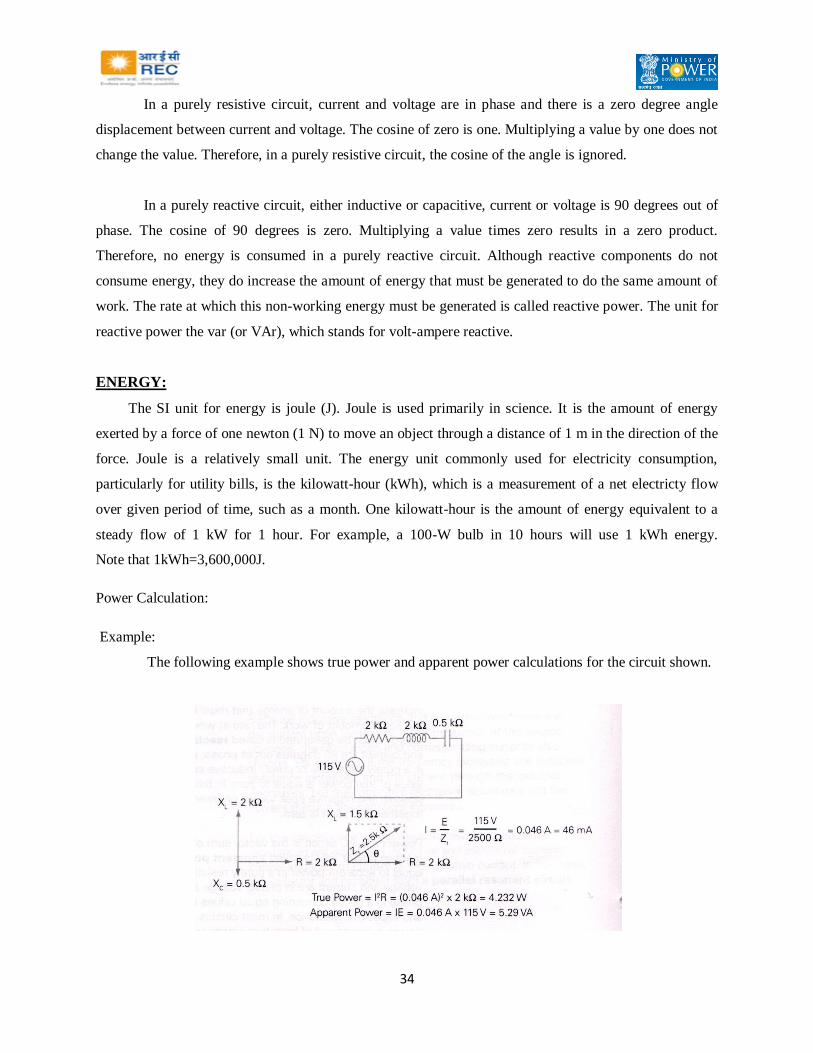
In a purely resistive circuit, current and voltage are in phase and there is a zero degree angle
displacement between current and voltage. The cosine of zero is one. Multiplying a value by one does not
change the value. Therefore, in a purely resistive circuit, the cosine of the angle is ignored.
In a purely reactive circuit, either inductive or capacitive, current or voltage is 90 degrees out of
phase. The cosine of 90 degrees is zero. Multiplying a value times zero results in a zero product.
Therefore, no energy is consumed in a purely reactive circuit. Although reactive components do not
consume energy, they do increase the amount of energy that must be generated to do the same amount of
work. The rate at which this non-working energy must be generated is called reactive power. The unit for
reactive power the var (or VAr), which stands for volt-ampere reactive.
ENERGY:
The SI unit for energy is joule (J). Joule is used primarily in science. It is the amount of energy
exerted by a force of one newton (1 N) to move an object through a distance of 1 m in the direction of the
force. Joule is a relatively small unit. The energy unit commonly used for electricity consumption,
particularly for utility bills, is the kilowatt-hour (kWh), which is a measurement of a net electricty flow
over given period of time, such as a month. One kilowatt-hour is the amount of energy equivalent to a
steady flow of 1 kW for 1 hour. For example, a 100-W bulb in 10 hours will use 1 kWh energy.
Note that 1kWh=3,600,000J.
Power Calculation:
Example:
The following example shows true power and apparent power calculations for the circuit shown.

35
Power Factor:
Power factor is the ratio of true power to apparent power in an AC circuit. As previously
indicated, this ratio is also the cosine of the phase angle.
In a purely resistive circuit, current and voltage are in phase. This means that there is no angle of
displacement between current and voltage. The cosine of a zero degree angle is one. Therefore, the
power factor is one. This means that all energy delivered by the source is consumed by the circuit and
dissipated in the form of heat.
In a purely reactive circuit, voltage and current are 90 degrees apart. The cosine of a 90 degree
angle is zero. Therefore, the power factor is zero. This means that all the energy the circuit receives from
the source is returned to the source. For the circuit in the following example, the power factor is 0.8. This
means the circuit uses 80 percent of the energy supplied by the source and returns 20 percent to the
source.
Another way of expressing true power is as the apparent power times the power factor. This is
also equal to I times E times the cosine of the phase angle.

36
AGGREGATE TECHNICAL & COMMERCIAL LOSSES
Technical Loss:
Every element in a power System (a line or a transfomer etc) offers resistance to power flow and
thus consumes some energy while performing the duty expected of it. The cumulative energy consumed
by all these elements is classified as “Technical Loss.”
Commercial Loss:
Losses occur on account of non-performing and under performing meters, wrong applications of
multiplying factors, defects in CT & PT circuitry, meters not read, pilferage by manipulating or by
passing of meters, theft by direct tapping etc. These are all due to non-metering of actual consumption
and are called commercial losses. The total of “Technical” and “Commercial” losses are termed are T&D
loss. It is unfortunate that in addition to the above, there is also a loss in revenue due to non-realisation of
billed demand. This is in addition to commercial losses and the aggregate of T&D loss and revenue loss
due to non-realisation is termed as “AT&C loss” (Aggregate technical and Commercial loss).
Therefore AT&C loss to the utility is the sum total of technical loss, commercial losses and
shortage due to non-realisation of total billed demand.
Example:
Units Input 100 MU
Unit billed 70 MU
Revenue collection with reference to billed demand: 90%
This means out of 70 MU, sales realization is for 90% of 70 MU i.e. 63%
T & D Losses 30 MU
ATC losses 37%
Power distribution systems in developing countries had to face phenomenal and rapid growth of
load in the last two decades. Distribution systems were expanded on adhoc and haphazard basis keeping
minimum investments in view.

37
Power systems are highly cost intensive and the investments needed to reduce technical losses by
every 1% are too high. Computer aided load flow studies are to be made to arrive at peak power loss and
also to arrive at technical losses based on load-duration curves. The Transmission system planning is
done on a separate footing that is keeping in view system adequacy, system security, reliability etc for n-1
and n-2. Conditions as per guide lines given by CEA. Losses in transmission systems are too small and
loss reduction is not an issue of focus in Transmission system planning.
FACTORS CONTRIBUTING FOR HIGH TECHNICAL LOSSES
The main factors that contribute for high technical losses are usage of lower size conductors, low
voltage pockets, lack of reactive power control, etc. The methods to reduce technical losses in the order
of priority based on cost impact are
1. Re configuration (changeover of loads or feeding source).
2. Re conductoring (Replacing existing conductor by higher size or conversion of single to double
circuit).
3. Shunt or series capacitor installation (switched and fixed).
4. Auto voltage booster.
5. Additional link lines.
6. Combination of two or more of the above.
7. As a last resort to go in for another sub-station followed up by reconfiguration.
8. Software tools are available for the studies to be made is termed as IOSP (Integrated Optimum
System Planning) in order to determine and prioratise such works, which result in maximum
LRVI (loss reduction and voltage improvement) with least investment. Based on cost benefit
ratio, the best option for investment can be chosen.
9. Combination of GIS and network analysis tools like Power Net.
However these studies shall be done keeping in view future load growth aiming for a five-year
horizon.
HVDS:
Of late, the Discoms have realized that the distribution systems shall be at high voltage and the L.T.
system shall be the least or eliminated as far as possible. HVDS or high voltage distribution systems by
converting existing LVDS is in progress in many Discoms reducing the technical losses appreciably.

38
This can be explained by one single illustration that for a 100 KVA load the amperage at 11KV is 5
Amps where as it is 140 Amperes at L.T. voltage of 415 Volts.
Amorphous Core Transformers:
Recently DTRs with amorphous core have entered Indian market and few utilities have installed
these. The core (magnetizing or no load losses) get substantially reduced. However the high cost is
coming in the way for large scale introduction. Efforts are being made to make amorphous core material
indigenously and the cost is expected to go down considerably.
Commercial Losses:
A good distribution network shall be in place for providing reliable power supply at assured voltage
levels to consumers and the same shall be with least technical losses. The commercial losses can be
reduced by accurate metering, efficient billing and prompt collections implementing.
Accurate Metering (A metering plan for installing meters with sustained accuracy).
Appropriate range of meter with reference to connected load.
Electronic meters with (TOD, tamper proof data and remote reading facility) for HT & HV services.
Intensive inspections by pooling up staff.
Reduce meter exceptionals.
Use energy Audit as a tool to pinpoint areas of high losses.
Eradication of theft.
AMR systems.
REASONS FOR LOSSES AND REMEDIES:
The major amount of losses in a power system is in primary and secondary distribution
lines; while transmission and sub-transmission lines account for only about 30% of the total losses.
Therefore the primary and secondary distribution systems must be properly planned to ensure that losses
are within acceptable limits.

39
CHAPTER – 3
ENERGY METERS, TYPES OF METERS AND THEIR USES AND LT
SINGLE PHASE AND POLY PHASE METERS
Introduction
1) Energy meter is vital equipment in the Electrical Industry. Especially in the present day context of
conservation of energy and conservation of resources, the meter accuracy assumes importance.
2) When the energy measurement is looked at it becomes clear that meter as such is a part of
metering and the energy measurement, therefore depends on not only accurate meter but the
metering system as a whole, which may comprise the associated current and potential
transformers and other wiring practices etc,.
3) When you think of an energy meter, we visualize an induction disc rotating from left to right and
registering the energy by pointers or set of drum type registers.
4) However, the advent of electro static devices and especially the microprocessor based devices
entering the field of metering, has slowly revolutionized the metering.
5) The microprocessor based metering has entered the field in a big way making the meter in fact, a
store house of data. The data is extractable with the help of electronic gadgets by either direct
contact or indirect modem.
Ferari Meters
1) The classical meter is an induction disc meter where rotation is proportional to the energy being
consumed
2) Since the disc is rotating, friction is inevitable and reduction of friction by employing highly
polished single jewel bearings, double jewel bearings or Magnetic suspension type are specified
in standards.

40
The Static Meters
1) The static meter and meters based on microprocessor are generally designed for recording not
only the energy by kWAh but also other parameters such as kVAh, KVARh, etc.
2) The CBIP Technical report No.88 covers the requirements of Static Electrical Energy meters for
Active, Reactive and apparent Energy measurement of accuracy classes 0.2, 0.5, 1.0 and 1.5.
3) The manufacturers are now being asked to make available meters such that a universal Meter
Reading Instrument (M.R.I), can read different makes of meters. For this purpose, they have to
make available the necessary software, through which the M.R.I can extract the meter reading.
Future Metering
1) The future for static meters appears to be very bright and microprocessors based meters are
probably going to dominate the field.
2) Some of the features which are advocated in this area are:
a) Meter with historical data with a few M.B. Memory to store various parameters.
b) Meters to be read by hand held MRIs.
c) Meter to be read by remote reading instruments.
3) The conservation of energy and load management systems demand intelligent meters which
switch off lights in an unused room or switch off the yard lighting automatically.
Some Important Aspects
1) At present, the static meters of class 0.2, 0.5 and 1 are dealt in the CBIP specifications No.88.
This is based on IEC specification No.687, which is for KWh meters only. The CBIP
specification arrived at the requirements of KVARh by suitably adopting the specification for
KWh. The accuracy of kVAh is still dependent on the accuracy of KWh and KVARh.
2) The concepts of KWh and rkVAh reference standards have come up in the older days of
Electromagnetic meters where a direct measurement of kVAh for the full range of power factors
was not available. The mechanical summator of L&G design is the technology available for
kVAh measurement, in those days.
41
3) The measurement of kVAh directly is possible now with the advent of Electronic Technology and
especially microprocessor based and it is time that an independent KVAH is to be thought of.
With this objective, an attempt is made to specify a kVAh meter in the CBIP report No.88
Conclusions
1. A universal type of meter reading is to be developed by the manufacturers of static meters, by
coming to an understanding.
2. Utilities shall go in for latest state-of-art metering technology in a phased manner to achieve
better load management and financial status. However, initially these schemes have to be
implemented as pilot schemes, in small areas, so as to assess the difficulties that arise during
operation.
Methods of Three Phase Power Measurement
There are basically two types of three phase power measurements namely
1) Three watt meter method (Three Phase three element meter or Three phase four wire meter)
2) Two watt meter method (Three Phase two element meter or Three phase three wire meter)
Three Watt Meter Method
In a three watt meter method, three potential coils and three current coils are provided in the meter.
Infact, a three phase four wire meter can be said to be three numbers of single phase parameters
accommodated in one frame, each element (i.e. potential and current coil) maintaining its own identity. A
single common disk is there to record the consumption. It is necessary that operation of each element is
checked separately when it is carrying load current to ensure that all elements are recording in positive
direction and that no negative torque is exerted in any element.
Two Watt Meter Method
A three phase three wire meter has two elements of each type instead of three elements as in the
case of three phase four wire meter. The basic principle of the operation is the same as that of a four wire
meter. A torque produced by two elements is equal to each other only when the power factor is in unity,
otherwise at other power factors, the individual torques produced by two elements are not equal and are of
varying proportion.
B element produces more torque at lagging power factor while the R element produces more
torque at leading power factor. This is assuming standard positive phase sequence of RYB. The red
42
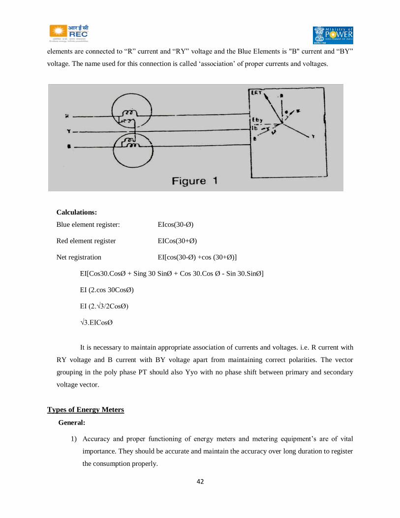
elements are connected to “R” current and “RY” voltage and the Blue Elements is "B" current and “BY”
voltage. The name used for this connection is called ‘association’ of proper currents and voltages.
Calculations:
Blue element register: EIcos(30-Ø)
Red element register EICos(30+Ø)
Net registration EI[cos(30-Ø) +cos (30+Ø)]
EI[Cos30.CosØ + Sing 30 SinØ + Cos 30.Cos Ø - Sin 30.SinØ]
EI (2.cos 30CosØ)
EI (2.√3/2CosØ)
√3.EICosØ
It is necessary to maintain appropriate association of currents and voltages. i.e. R current with
RY voltage and B current with BY voltage apart from maintaining correct polarities. The vector
grouping in the poly phase PT should also Yyo with no phase shift between primary and secondary
voltage vector.
Types of Energy Meters
General:
1) Accuracy and proper functioning of energy meters and metering equipment’s are of vital
importance. They should be accurate and maintain the accuracy over long duration to register
the consumption properly.
43
2) Meters are to be selected according to the load characteristics. Before installing them, they
should be tested. Connections should be proper and at the time of commissioning, registration
of meters should be checked on load. Periodical checking has to be conducted so that the
complete equipment remains well maintained. This will assure proper functioning of the
equipment over a long period.
3) Good quality of meters maintain high accuracy over a long period of 15/20 years with
varying load without recalibration or maintenance, provided they are installed and
commissioned properly and protected from dust, vermins and mis-handling. However, test
checks are to be applied from time to time.
Types of Meters:
1) Single phase meters
2) 3-phase 4 wire meters -L.T
3) 3-phase 3 wire meters -L.T
4) 3-phase 4 wire CT operated meters with MD indication
5) 3-phase 3 wire CT operated meters with MD indication
6) Special meters: 3- phase 3 wire or 3- phase 4 wire Tri-vector or bivector meters(H.T meters)
7) Summation meters for parallel feeders at consumer end.
Electronic Meters
Electronic tri-vector meters are now available for providing at the Substations or at the H.T.
consumer’s premises. The special features are described below.
Special Technical Features of Electronic Tri-Vector Meters
The display system of the meters, now consists of
i. Active Energy utilization KWh
ii. Reactive Energy utilization KVARh
iii. Apparent Energy utilization kVAh
iv. Peak Maximum demand Kva
kW (with lagging PF)

44
v. a) Cumulative demand kVA
b) Billed MD for previous months
vi. Reset Counter
vii. Power Factor
viii. Frequency
ix. Occurrence of missing PT. for supply of voltage
x. Time of the day metering
xi. Time-interval for time of the day metering
xii. Energy- import/export
xiii. Tamper information
xiv. Raising demand with elapsed time
The meters could therefore be used at S/s ends or at the consumer’s end to have accurate data-base and
utilization of energy.
The meters meet with IEC 687 standard and are suitably designed to record accurately with
variation in voltage from +10 to -3% and frequency ±5%. The meters are of 0.5 accuracy. The battery to
meet voltage demand of the circuit is of 3 volt lithium.
The multiplying factor can be kept at unity, in order to avoid error due to use of various ratings of
CTs and PTs. Three seals are provided, one on the front cover, one for terminal cover and one for M.D.
reset button. All other features are built-in, to display the details described above. The meters are
designed for CT. Ratios of 5 amps or 1 amp on secondary side and PT. ratio of 110 volts on secondary
side.
Installation of Meters with CTs & PTs
In order to increase the range of an ammeter, shunts are generally used. A low resistance shunt is
placed in parallel with an ammeter to measure current which is more than that which the instrument itself
can carry. Similarly in order to increase the` range of a voltmeter, a resistance (with negligibleinductance)
is used in series with the instrument. This type of arrangement is used in multi-range testing instruments.

45
A very general method of increasing range of A.C. instruments is to use instrument transformers
with ammeters, voltmeters or watt meters etc. The transformers are either current transformers or
potential transformers, which are respectively used to increase current or voltage range of instruments.
The advantages of use of instrument transformers are as follows:
(i) Single range instruments can be used to cover large current or voltage range. The usual ranges
of ammeters and voltmeters are 5 amperes or 1 ampere and 110 volts. .
(ii) The indicating instruments can be located away from the H.T. circuit and do not require
insulation for higher voltage.
(iii) A split core CT. with primary winding on which secondary winding is also wound can be used to
measure the current in heavy current bus-bar without breaking the current circuit.
Installation of Meters
Before installation of meters with CTs and PTs, metering equipment has to be tested for
1. Correct polarity of CTs and PTs.
2. Continuity test of primary and secondary windings.
3. Ratio test by primary injection kit for CTs.
4. Voltage ratio test for PTs by applying L.T. voltage on the primary side.
5. Insulation resistance.
6. Terminal markings as per name plate details.
Checks of Polarities & Ratios
Three phase 415V supply is given to High Voltage terminals of PT and the secondary voltages
between phase-to-phase and phase-to-neutral are measured to ensure the PT. ratio. Correct phasing can be
identified by giving voltage to only one phase after another. Polarity is checked by touching the primary
terminals with +Ve and –Ve leads from a battery and observing the direction of deflection on a center
zero D.C. voltmeter connected to the corresponding phase on the secondary side.
Current Transformers:
The ratio is determined by primary injection kit. This assumes greater importance when CTs have
multiple ratios. As the energy to be computed is very large, this test is to be done very meticulously.

46
CHAPTER – 4
CONSUMER INDEXING
Application of GIS in Distribution: Objective of Consumer Indexing
The Objective of Consumer indexing is to enhance the efficiency of distribution system in terms
of quality of power and earn increased revenue by reducing outages and T & D losses (both technical and
commercial) and to encompass the functions of different disciplines into the main stream of operational
hierarchy through wide networking.
Consumer & Asset Indexing – Different Phases
i. The first phase shall be to uniquely index each customer asset based on the electrical system
codification, from the source of supply upto the customer end. The completion of this phase shall
enable feeder wise energy accounting (33KV feeder & 11 KV feeder) and also DTR wise energy
accounting.
ii. The second phase of the indexing is to create a database for each asset and individual customer
indicating the exact geographical location. This phase shall include walk over survey for physical
verification at the field level and ensure that all consumers are covered.
iii. The ultimate objective shall be to ensure that each and every consumer is correctly indexed to
‘point of sale’ of Power, and should be reconciled with the Section office/ERO records.
GIS Based Mapping – Challenges prior to implementation
i. Non availability of network information/data base
ii. Non existence of regular updating system
iii. Non-availability of any specific manual
iv. Non-availability of any IT enabled tool to provide requisite analytical reports correctly & quickly
v. The distribution company cannot work efficiently and economically without availability of
technical or consumer related data base
vi. Non- updating and not recording day-to-day changes in the system.
vii. Analysis & improvement of the system, is not possible in the absence of data.

47
GIS Based Mapping for Electrical Network:
i. Mapping of complete electrical network up to low voltage system and customer supply points
with latitudes and longitudes overlaid on satellite image and/or survey of India maps.
ii. Includes the incorporation of present details of localities, landmarks, network details up to
consumer level.
GIS Based Mapping – The Need
i. Inventory of Existing Network
ii. Easy access to Network details
iii. Easy access to Consumer Data
iv. Data export for Analysis & Network Improvement of existing system
v. Load growth projections (load density in MW/Sq Km)
GIS Based Mapping – Requirements
i. Base Map (Digitized or image)
ii. DGPS (Differential Geographical Positioning System) to fix salient topographical details
iii. Handheld GPS (Global Positioning System) to locate network details up to consumer level
iv. GIS software package

48
GIS Based Consumer Indexing – Activities Involved
i. Preparation of Base Map
ii. Fixing Topographical Details
iii. GPS Survey
iv. Single Line Diagrams
v. Mapping and Documentation of network
vi. Mapping and Indexing of the Consumer
vii. Database for Electric Network
viii. Consumer Data Base Development
ix. Segregation of consumers, 11 KV Feeders wise and Distribution Transformer Wise
GIS Based Consumer Indexing – Preparation of Base Map
i. Obtaining the Base Map of the area to be mapped from ISRO/Remote Sensing Application
Center/SOI/other sources which would have coarse level information
ii. Digitization of Base Map
iii. Geo-referencing the Map
GIS Based Consumer Indexing – Fixing Topographical Details
Using DGPS (Differential Geographical Positioning System) the salient topographical details of
the area like road junctions, important landmarks can be accurately fixed.
GIS Based Consumer Indexing – GPS Survey
Handheld GPS with resolution of 1m can be used to locate the
substations/transformers/poles/consumer points etc. Attribute data of each pole and other facilities
collected during the survey – such as asset data, Transformer details, services, type of use, load, consumer
details, etc.

49
Mapping and Documentation of network
i. Develop indexing for the electrical sub-transmission and distribution network in the specified
circle from 33KV, 11KV to LT.
ii. Each of the elements like 33KV and 11KV feeders, feeder branches, Distribution transformers
shall be uniquely indexed with defined relationships based on the normal mode of feeding
envisaged.
iii. Network documentation is required to have the Electrical address and feeding arrangement of
localities and consumers for carrying out Energy Accounting and maintenance of supply.
iv. Coded Asset data of sub-transmission and distribution networks of the circle shall be delivered
sub-division-wise. The coding shall be such that any additional modification to the network can
be assigned codification without any difficulty.
v. The documentation, indexing and coding for the various elements of the network, such as 33KV
feeders, 33/11KV substation, 33/11 KV Transformers, 11KV feeders, Distribution Transformer
(DTRs), L.T. Lines connected to the Distribution Transformer is to be carried out in such a way
that it would be possible to relate the following:
The location of the Network with reference to Geographical Area of the Division &
Subdivision.
The location of 33/11KV substation and related feeders.
The main road, branch road and the lane, through 11KV feeder and L.T Lines passes.
The location of the L.T. Lines and its pole with respect to the main road, branch road and
the lane.
vi. Based on the details of Network available with the circles, divisions and sub-divisions, pole to
pole survey of 33KV, 11KV and L.T. lines existing in that area is to be conducted and
Distribution Network from 11KV to L.T System is to be developed.
vii. During survey of Lines, the line length, type and size of the conductor used, type and number of
various types of poles existing are to be documented.

50
viii. The Sub Transmission and Distribution Network indicating details of 33KV feeders, 33/11 KV
Substation, 11KV feeders, 11/0.4KV Distribution Transformers and L.T. lines is to be developed
and superimposed on the geographical map so that the physical position of the lines, substation is
known on the Map.
ix. The interconnections between sections to section are also to be compiled and marked.
x. The network Documentation shall have the facility for tracing the electrical connectivity for any
part of the network. That is, it shall be possible to find out all elements Electrically connected to
any particular line or transformer and distinguishing points are to clearly marked.

51
GIS Based Consumer Indexing – Mapping and Indexing of Consumer
i. The purpose of Mapping and Indexing of the consumers is to identify and locate all the
consumers on geographical map, which are being fed from distribution Mains of the DISCOM.
ii. There may be cases where electrical connection exists but it does not exist in ERO record.
iii. It may be a case of unauthorized connection or non-legderization of connection.
iv. On the other hand, there may be cases where a connection exists in record of DISCOM but it may
not exist physically at site.
v. In this case there can be possibility that
a. The connection might have been disconnected long back but the record of
DISCOM may not have been updated
b. It may be the case where the address and other details of the consumer are not
correctly recorded.
vi. The correct position to be assessed and reported to DISCOM. The factual position is to be found
out and the report/documentation is to be done accordingly.
vii. The L.T. lines coming out from Distribution Transformer are to be checked pole to pole.
viii. All service connections from the L.T. Lines/mains are to be checked with reference to the
consumers to whom these service lines are feeding the load.
ix. Door – to – Door survey of the locality is to be conducted for checking the existence of the
connection in the premises and verify the following: The Existing connection is ledgerized and
available in commercial record of DISCOM. If not, report of unledgerized connection is to be
made out; Status of connection whether it is live or disconnected. The commercial record of
consumer with DISCOM is to be verified.
GIS Based Consumer Indexing – Database for Electric Network
i. The database of the Network should be made in suitable software so that the changes in the
network can be updated and queries may be used to find out the Network details, like the details

52
of the equipment at the substations, the length of lines, number of transformers and breakers etc
in any part of the Network.
ii. The same should be possible to update and maintain on periodic basis
iii. The following data in respect of 33/11KV Lines, 11 KV feeders, 11/0.4KV Distribution
Transformers, LT lines and consumers of all categories is to be collected and documented in the
Database.
Data of 33KV Feeder
Name of the feeder
Code No. of the feeder
Name of the feeding EHT SS
Length of the line
Details of meter installed at EHT SS: Type/ Make/ S.No/ Multiplying factor
Data of 33KV/11KV SS
Name of the Division
Name of the Sub Division
Name of the Section
Name of the Substation
Code No. of the Substation
Capacity of the substation with particulars of Power transformers (No. of Power transformers
installed, capacity and voltage ratio wise)
Name of the feeding primary EHT substation
Name and length of 33KV Line feeding the substation from the primary substation
Date of commissioning of substation
Total No. of 33KV or 11KV Circuit Breakers installed
Incoming (33KV) – Nos.
LV control (11KV) – Nos.
Feeders (11KV) – Nos.
Total No. of feeders connected

53
Data of each Power Transformer in the substation
Maker’s SI.No. of the transformer
Make of the transformer
Capacity
Date of commissioning
Voltage ratio
Current rating
No. of Taps on the transformer
% Impedance
Date of last overhaul
Data of 33KV and 11KV Circuit Breakers in the substation
Details of each Circuit Breaker
Make of the Circuit Breaker
Maker’s SI.No.
Name of the connected 33KV or 11KV feeder
Code of the feeder
Date of commissioning
Current rating
Rupturing capacity
Maximum load recorded with date and year
Data of 33KV and 11KV Circuit Breakers in the substation
Type of protection provided
Details of relay installed
Details of C.T installed: Make /C.T Ratio Available /Connected CT. Ratio /Class of Accuracy
/V.A Burden
Data of 33KV and 11KV Circuit Breakers in the substation
Details of P.T. installed
Make of P.T.
Voltage Ratio
V.A. Burden

54
Details of meter installed: Type/ Make/ SI.No./ Multiplying factor
Availability of data logging facility
Data of each consumer connected at 33KV or 11KV
SI.No
Name of 11KV feeder and code
Pole No
Name and Address of the consumer
S.C. No
Contracted Load
Data of Distribution Transformer
Connected to 11KV feeder
11KV feeder No. / Code No.
Location of D.T.
Capacity of Transformer
Voltage Ratio
Code of the Transformer
Name of the Manufacturer
Manufacturer’s Serial No.
Year of the Manufacture
Date of Commissioning
Meter Details
Meter No
Name of meter manufacturer
Year of manufacture
Mechanical/Electronic
Meter on primary/secondary (side)
Data of L.T. Feeder
Connected to D.T.R (Code No.)
Location of D.T.R
D.T.R Code No.

55
L.T. Feeder Name
L.T. Feeder No.
Length of Line – the length of three phase, two phase and single phase line is to be worked out
and segregated conductor wise
Single phase Line – Conductor Size
Data of connected Consumers
D.T. Code
L.T. Ckt Code
Pole No.
Details of Consumers: Sc. No / MR Book No / Name & Address / Load/Category / Nature of
supply / 3 Phase / Single Phase
GIS Based Consumer Indexing – Consumer Database Development
Following data in respect of various consumers existing in the area of the town is required to be
documented in software before development of CONSUMER DATABASE
Consumer Details: Name of the Consumer / Father / Husband name / Address / Phone No. /
Consumer Code No. / Date of connection / Pole No. of L.T. mains to which the consumer is
connected / Service connection Number / Meter Reading Book no. of the Consumer / Contracted
Load / Category / Tariff Applicable / Type of supply (Single Phase / Three Phase)
Name of the Division / Subdivision / Section
Assessed monthly consumption of the consumer based on connected load.
Type of Service Line – Overhead line / Cable Service
Meter Details : Meter Number / Type of Meter / Make of Meter / Year of Manufacture
Physical Condition of the Meter & Seal: Viewing Glass / Seal on the meter body / meter terminal
plate / Sign of Tampering (if any)
Physical Location of the Meter: Approachability – Inside or approachable from outside /
Readability – Height of mounting
Identifiability – Clustering of Meter for multiple services
Operational status of meter: OK / Dial not rotating / Digits not visible / Smoky / Damaged /
Digits not Changing / Figure upset
Status of wiring / service cable: OK / Cuts / Joints / tampering / clustered

56
GIS Based Consumer Indexing – Segregation of consumers, 11 KV Feeders wise and
Distribution Transformer wise
i. The connected consumers are to be identified and segregated Distribution transformer wise and
11KV feeder wise. The meter reading of distribution transformers is to be segregated 11KV
feeder wise. The segregated meter readings identified for particular DT should contain the entire
consumers connected to the respective DT
ii. To identify the areas of high Energy Losses it is essential to work out the losses, Distribution
Transformer wise and 11KV feeder wise.
iii. The losses are to be assessed by subtracting the total energy of all the consumers billed,
connected to the Distribution Transformer / 11KV feeder, from the energy sent / metered on
Distribution Transformer / 11KV Feeder respectively.
iv. For doing so it is essential that the connected consumers are segregated Distribution Transformer
wise and 11KV and 33KV Feeder wise.
GIS Based Consumer Indexing – Deliverables of consumer indexing phase
Coded Asset data of sub-transmission and distribution networks of the circle, sub-division-wise
as soon as they are completed. The coding shall be such that any additions / modification to the
network can be assigned codification without any difficulty.
The connected consumers are to be identified and segregated Distribution transformer wise and
11KV feeder wise. The segregated meter readings identified for particular DT should contain the
entire consumers connected to the respective DT.
List of consumers with the relevant codes of indexing generated to be delivered feeder wise.
GIS Based Consumer Indexing – Capabilities of Indexed Customer Database
Shall be capable of allocating a unique identification number known as Customer
Identification Number (CIN) to each customer.
The system shall keep track of the location in the network from where a particular
customer is fed. This shall be achieved in conjunction with the network data created.

57
Provision shall be made for linking and maintaining records (in Registers / Ledgers) of
the utility’s customer’s identification number as parameter, existing before
implementation / adoption of the customer indexing work under this specification.
The database shall be flexible for making changes in the customer profile as required.
This means changes such as customer name, location, connected load, category of
connection, maximum demand, type of connection (HT / LT), and tariff related
information.
Sorting and viewing electrical area or feeder / administrative area wise customer details.
Handling requests for new connections. This shall enable a paperless handling of all
events from receipt of request to processing / tracing the request at all stages within the
business process and providing the connection and updating of customer database.
GIS Based Consumer Indexing – Preparation of GIS
i. GIS includes the GPS survey network overlaid on Base map with all attributes of each pole.
ii. Includes inventory for asset management
iii. Includes loads on the system
iv. Also associated analysis
GIS Based Mapping – Software – Capabilities
i. Network Creation – SLD / equipments / geographic representation / SS design
ii. System analysis – Cost benefit analysis / what if analysis / reconductoring / network
configuration / load flow studies / load balancing / short circuit studies
iii. System optimization – Switch optimization / overload equipment / network reconfiguration
iv. Reports – Transformer summary / consumer summary / energy audit / inventory / complaints
v. Trend analysis – Trends in electricity demand plays a significant role in the forecast of future
demand if the area is already exposed to electrical power usage and past records are available.
Data required for Trend analysis include category wise number of services, connected load,
energy consumption for the last 5 to 10 years etc. These parameters can be incorporated in GIS
for Trend analysis
Growth rate of energy – year wise and cumulative growth rate of energy for the period

58
Share of electrical energy consumption among different sectors year wise and the average
for the period.
Energy consumption per service year wise and the average for the period
Growth rate of service connections year wise and cumulative growth rate for the period
Connected load per service connection year wise and the average during the period
What is achieved so far, by some of the power utilities?
The entire network is available along with asset details & land base, digitally.
Feeder wise segregation consumer wise & DT wise.
Asset & consumer is indexed.
Road map for DISCOMs, for optimum use of GIS
a. Every DISCOM has to aim at the application of GIS for load research, where the GIS can assist in
determining the sample selection and in refining load shapes by associating customers with other
demographic characteristics that would include assessed value of homes, building footprint, heating
type and weather patterns. In the Boston area, for example, during a typical summer day,
temperatures can vary 15 degrees depending on the distance from the ocean. Wind speeds in the
downtown area are different than those in the suburbs. Because GIS can plot temperature and wind
speed gradients geographically for each hour, it is possible to enhance load shapes by analyzing the
data spatially. Even with load profiling, it would seem likely that analyzing that automated meter
reading (AMR) systems will continue to penetrate the market, encouraging the industry to adopt GIS
to build out and manage the AMR and associated communications infrastructure.
b. The most common problem about having multiple systems in any organization is duplication of data
and the up-dation philosophy necessary to keep the data updated. It is the primary requirement of the
utility that all systems work in an integrated manner. For this purpose it is required that GIS system
be integrated with SCADA system. SCADA system would export required data like the equipment
status, the topology of data to all other system like GIS and customer care system. Similarly Billing
system would act as the main database for consumer addition. GIS system would automatically
update the consumer data based on some triggers in the billing database. The customer care system
would analyse the feasibility of the new connection based on location data and availability of poles
and DTs from the GIS and then analyze the present capacity before determining the feasibility of the
same. Besides it would also get the latest status data from the SCADA system thus helping in
customer resolution for outage management Integration of GIS with SCADA, Trouble Call

59
Management, MBC (Metering, Billing & Collections) etc., to serve as an effective tool towards
improving internal efficiency of DISCOMs and to earn total consumer.
Conclusion
GIS database shall form the source of sufficiently accurate data on medium – voltage distribution
network assets. Its spatial data model comprises topological information on network elements
(connectivity, sharing, adjacency, proximity, overlapping, etc) providing the foundation for spatial
analyses and reasoning. The accurate positions and lengths of the existing cables and all their segments in
the cable accurate positions and lengths of the existing cables and all their segments in the cable route
between two substations are defined. The exact locations of existing and proposed locations of future-
planned substations, as a result of load growth analyses and predictions, are known. The possible routes
for new cables in keeping with urban zoning plans, ecological and aesthetic constraints are also known
from database spatial queries and graphic presentation of observed geographic area. The knowledge of
precise cable lengths (i.e. segments of the cables between substations) and other corresponding attributes
(e.g. the year the cable segment was laid down, construction type, material, cross section, operating
voltage) for the existing cables and selected set of possible new cable routes enables the better electrical
analyses and planning of the network.

60
CHAPTER – 5
SAFETY
ELECTRICITY PARAMETERS RELATED TO SAFETY
I. Electricity:
Use of electricity is so widespread that there may be hardly anyone who has not experienced a
slight electric shock at one time or other. Voltages (of a circuit) cause currents to pass through any
resistance. The resistance of the human body at best is of the order of 9000 ohms and at the worst is 500
ohms. A major part of the resistance is due to the skin. The internal resistance of the body varies from 200
to 800 ohms. So, when the skin is wet and when perspiring freely, the body resistance is at its worst.
The values of various resistances given above are for 230 volts A.C. of 50 HZ frequency. This is
the frequency used in houses, commercial premises, Hotels etc., in India. The body resistance varies
inversely with the voltage. That means, at lower voltages the body resistance is very high and at higher
voltage it goes on reducing. Since current through the body will depend on body resistance and applied
voltage, at lower voltage as body resistance is high, the magnitude of current will be lower and so is the
shock effect.
In shocks from AC currents of normal power frequency, the shock current is sinusoidal with
frequency of 50 Hz. The frequency of heart beat is also in this range. The AC shock current frequency
disturbs the frequency of heart signals. Also, Direct Current, normally known as D.C. is four times safer
than A.C. That is body resistance is four times more then what is mentioned earlier when D.C is used
instead of A.C. In India, Calcutta is the only city where D.C. is still used in some areas. In Calcutta, if you
ask a washer man whether he likes A.C. or D.C. iron he will invariable say D.C. If you ask him for the
reason, he will say that A.C. catches you in case of shock where as D.C. gives only a mild shock.
II. Effect of Current:
As mentioned earlier the current passing through the body causes all the damage. Of course,
time duration is also important. The third element is the path of the current through the body. If the path
involves the heart, the damage is more. If the path is through the left hand to earth, the heart will
invariably get involved.
Before considering the effect of the magnitude of current on the human body, certain
fundamentals regarding voltage and current need to be cleared by a simple example
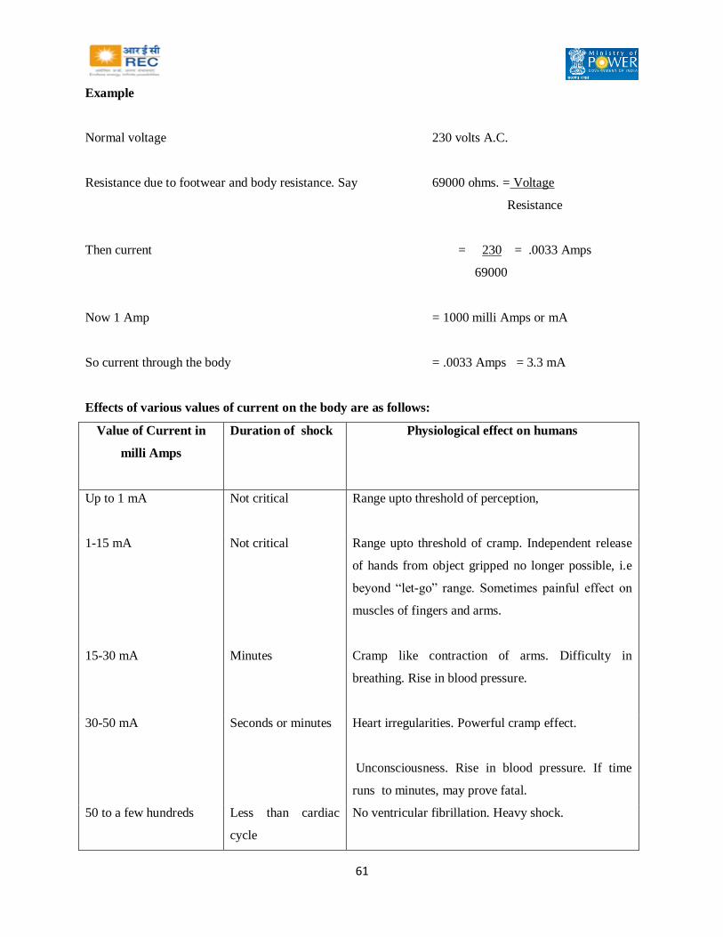
61
Example
Normal voltage 230 volts A.C.
Resistance due to footwear and body resistance. Say 69000 ohms. = Voltage
Resistance
Then current = 230 = .0033 Amps
69000
Now 1 Amp = 1000 milli Amps or mA
So current through the body = .0033 Amps = 3.3 mA
Effects of various values of current on the body are as follows:
Value of Current in
milli Amps
Duration of shock Physiological effect on humans
Up to 1 mA
Not critical Range upto threshold of perception,
1-15 mA Not critical
Range upto threshold of cramp. Independent release
of hands from object gripped no longer possible, i.e
beyond “let-go” range. Sometimes painful effect on
muscles of fingers and arms.
15-30 mA Minutes
Cramp like contraction of arms. Difficulty in
breathing. Rise in blood pressure.
30-50 mA Seconds or minutes
Heart irregularities. Powerful cramp effect.
Unconsciousness. Rise in blood pressure. If time
runs to minutes, may prove fatal.
50 to a few hundreds Less than cardiac
cycle
No ventricular fibrillation. Heavy shock.
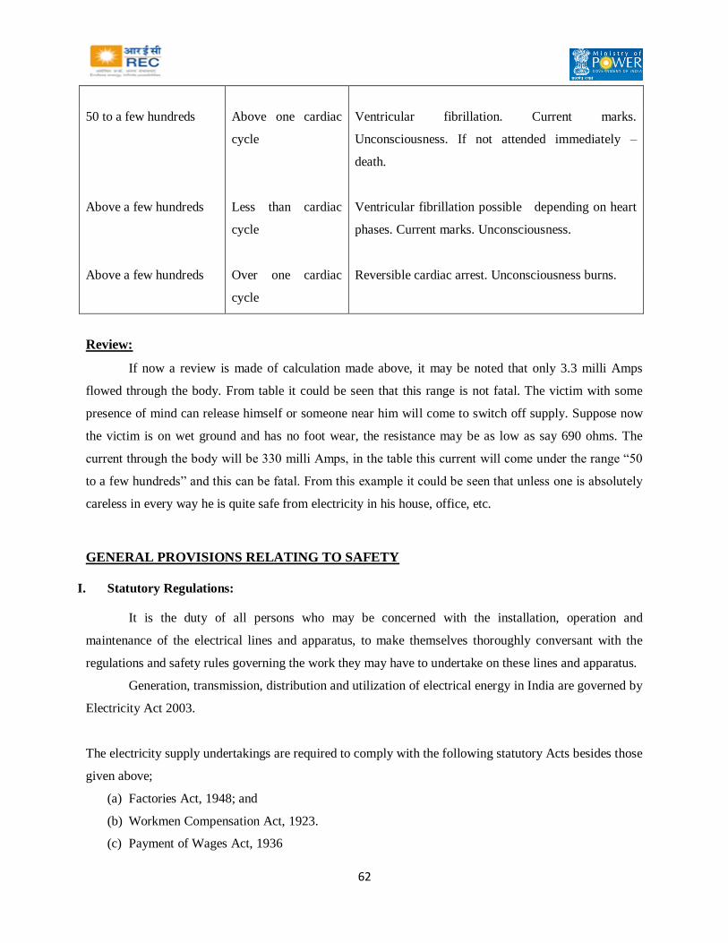
62
50 to a few hundreds Above one cardiac
cycle
Ventricular fibrillation. Current marks.
Unconsciousness. If not attended immediately –
death.
Above a few hundreds Less than cardiac
cycle
Ventricular fibrillation possible depending on heart
phases. Current marks. Unconsciousness.
Above a few hundreds Over one cardiac
cycle
Reversible cardiac arrest. Unconsciousness burns.
Review:
If now a review is made of calculation made above, it may be noted that only 3.3 milli Amps
flowed through the body. From table it could be seen that this range is not fatal. The victim with some
presence of mind can release himself or someone near him will come to switch off supply. Suppose now
the victim is on wet ground and has no foot wear, the resistance may be as low as say 690 ohms. The
current through the body will be 330 milli Amps, in the table this current will come under the range “50
to a few hundreds” and this can be fatal. From this example it could be seen that unless one is absolutely
careless in every way he is quite safe from electricity in his house, office, etc.
GENERAL PROVISIONS RELATING TO SAFETY
I. Statutory Regulations:
It is the duty of all persons who may be concerned with the installation, operation and
maintenance of the electrical lines and apparatus, to make themselves thoroughly conversant with the
regulations and safety rules governing the work they may have to undertake on these lines and apparatus.
Generation, transmission, distribution and utilization of electrical energy in India are governed by
Electricity Act 2003.
The electricity supply undertakings are required to comply with the following statutory Acts besides those
given above;
(a) Factories Act, 1948; and
(b) Workmen Compensation Act, 1923.
(c) Payment of Wages Act, 1936

63
In addition to the statutory regulations mentioned above, the safety instruction given in this
Manual for the guidance of the staff employed in connection with the execution of work on or near the
electric lines and apparatus or for their operation and maintenance, should be strictly complied with at all
times.
It shall be the responsibility of the person-in-charge to interpret and explain correctly the rules
and regulations to all the staff concerned and to ensure that the staff thoroughly understands the same.
II. Definitions:
(a) ‘APPROVED’ means a type sanctioned for use by the undertaking.
(b) ‘AUTHORISED PERSON’ means a competent person appointed in writing by a competent
authority to carry out specific duties incidental to the transmission, conversion, transformation,
distribution or utilization of electrical energy as per the provisions of Rules.
Note: - No person shall be authorised unless he is competent to perform the duties for which he is
authorised and no person shall be deemed to be authorised unless his name has been entered in a list
maintained in the office or premises of the person authorizing him and the purpose for which the person
has been authorised is stated side by side therein and attested by the authorised person and the person
authorising him.
(c) ‘COMPETENT PERSON’ means a person who has sufficient technical knowledge and / or
experience of a particular branch of engineering or science and is normally of the rank of not
lower then Executive Engineer.
(d) ‘EARTH’ means the conducting mass of earth or a conductor connected to it through very small
impedance.
(e) ‘ELECTRICAL APPARATUS’ means all electrical apparatus pertaining to the transmission,
distribution and utilization of electrical energy.
(f) ‘ISOLATED’ means physically disconnected from all sources of electrical energy and in manner
that disconnected contacts of the isolating switch are normally visible.

64
(g) ‘LIVE’ in respect of any apparatus, equipment and conductor means electrically charged.
(h) ‘MECHANICAL EQUIPMENT’ means all mechanical equipment pertaining to the transmission,
distribution and utilization of electrical energy.
(i) ‘PERMIT TO WORK’ means a form of declaration issued by an Authorized Person to another
Authorised Person-in-charge of the work to be carried out on or adjacent to any electrical
apparatus or chemical equipment for the purpose of making known to such latter person exactly
what apparatus or equipment have been made dead, isolated and discharged are safe to be worked
on, and gives the description of the work required to be carried out under the permit.
(j) ‘TEMPORARY EARTH’ means an earth defined under para (d) above, but applied temporarily
at the point of work on any electrical apparatus during actual working thereon after the issue of
Permit to Work.
(k) ‘VISITOR’ means a person other than an employee permitted to enter a work point under a
permit by the undertaking.
General conditions relating to supply and use of electricity:
Precautions against leakage before connection:
1) The supplier shall not connect with his works the installation or apparatus on the premises of nay
applicant for supply unless he is reasonably satisfied that the connection will not at the time of
making the connection cause a leakage from the installation or apparatus of a magnitude
detrimental to safety which shall be checked by measuring the insulation resistance as under-
(i) All equipments shall have the insulation resistance (IR) value as stipulated in the relevant
Indian Standards.
(ii) On application of 500 V DC between each live conductor and earth for a period of one
minute, the insulation resistance of installation and equipment of voltage not exceeding 650
V shall be atleast 1 MEGA OHM or as specified in the relevant Indian Standards.
(iii) On application of 2.5 kV DC between each live conductor and earth for a period of one
minute, the insulation resistance of installation and equipment of voltage exceeding 650 V
but not exceeding 33 KV shall be atleast 5 MEGA OHM or as specified in the relevant Indian
Standard.

65
Leakage on consumer’s premises:
1. If the Electrical Inspector or the supplier has reasons to believe that there is leakage in the system
of a consumer which is likely to affect injuriously the use of electricity by the supplier or by other
persons, or which is likely to cause danger, he may give the consumer a notice in writing that he
desires to inspect and test the consumer's installation.
2. If on such notice being given, the consumer does not give all reasonable facilities for inspection
and testing of his installation, or when an insulation resistance of the consumer's installation is so
low as to prevent safe use of electricity, the supplier may, and if directed so to do by the
Electrical Inspector shall discontinue the supply of electricity to the instal1ation but only after
giving to the consumer forty eight hours notice in writing of disconnection of supply and shall not
recommence the supply until he or the Electrical Inspector is satisfied that the cause of the
leakage has been removed.
Supply and use of electricity:
1. The following controls of requisite capacity to carry and break the current shall be placed as near
as possible after the point of commencement of supply so as to be readily accessible and capable
of being easily operated to completely isolate the supply to the installation, such equipment being
in addition to any equipment installed for controlling individual circuits or apparatus, namely.
(i) A linked switch with fuse or a circuit breaker by consumers of voltage which does not
exceed 650 V;
(ii) A linked switch with fuse or a circuit breaker by a consumer of voltage exceeding 650 V
but not exceeding 33 kV having aggregate installed transformer or apparatus capacity up to
1000 KVA to be supplied at Voltage upto 11 kV and 2500 KVA at higher voltages (above
11 kV and not exceeding 33 kV);
(iii) A circuit breaker by consumers at voltage exceeding 650 V but not exceeding 33 kV having
an aggregate installed transformer and apparatus capacity above 1000 KVA and supplied at
voltage upto 11 kV and above 2500 KVA at higher voltages (above 11 kV and not exceeding
33 kV).
(iv) A circuit breaker by a consumer of voltage exceeding 33 kV.
66
Provided that where the point of commencement of supply and the consumer apparatus are near
each other, one linked switch with fuse or circuit breaker near the point of commencement of supply shall
be considered sufficient.
2. In case of every transformer the following shall be provided; namely:-
i. On Primary side for transformers, a linked switches with fuse or circuit breaker of
adequate capacity:
Provided that the linked switch on the primary side of the transformer may be of such capacity as
to carry the full load current and to break only the magnetizing current the transformer:
Provided further that for all transformers:
(a) having a capacity of 5000 KVA and above installed before the year 2000; and
(b) having a capacity 1000 KVA and above installed in or after the year 2000, a circuit
breaker shall be provided;
Provided also that the linked switch on the primary side of the transformer shall not required for
the unit auxiliary transformer and generator transformer;
ii. In respect of all transformers installed in or after the year 2000, on the secondary side of
all transformers, a circuit breaker of adequate rating shall be installed;
Provided that for Suppliers’ of transformers of capacity below 1000 KVA, a linked
switch with fuse or circuit breaker of adequate rating shall be installed on secondary side.
3. Except in the case of composite control gear designed as a unit each distinct circuit is to be
protected against excess energy by means of suitable cut-out or a circuit breaker of adequate
breaking capacity suitably located and so constructed as to prevent danger from overheating,
arcing or scattering of hot metal when it comes into operation and to permit for ready renewal of
the fusible metal of the cut-out without danger.
4. The supply of electricity to each motor or a group of motors or other apparatus meant for
operating one particular machine shall be controlled by a suitable linked switch or a circuit
breaker or an emergency tripping device with manual reset of requisite capacity placed in such a
position as to be adjacent to the motor or a group of motors or other apparatus readily accessible
to and easily operated by the person incharge and so connected in the circuit that by its means all
67
supply of electricity can be cut off from the motor or group of motors or apparatus from any
regulating switch, resistance of other device associated therewith.
5. All insulating materials shall be chosen with special regard to the circumstances of their proposed
use and their mechanical strength shall be sufficient for their purpose and so far as is practicable
of such a character or so protected as to maintain adequately their insulating property under all
working conditions in respect of temperature and moisture; and
6. Adequate precautions shall be taken to ensure that no live parts are so exposed as to cause danger.
7. Every consumer shall use all reasonable means to ensure that where electricity is supplied by a
supplier, no parson, other than the supplier shall interfere with service lines and apparatus placed
by the supplier on the premises of the consumer.
Provisions for supply and use of electricity in multi - storeyed building more than 15 meters in
height:
(1) The connected load and voltage of supply above which inspection is to be carried out by an
Electrical Inspector for a multi-storeyed building of more than fifteen meters height shall be
notified by the Appropriate Government.
(2) Before making an application for commencement of supply or recommencement of supply after
an installation has been disconnected for a period of six months or more, the owner or occupier of
a multi-storeyed building shall give not less than thirty days notice in writing to the Electrical
Inspector specify therein the particulars of installations and the supply of electricity shall not be
commenced or recommenced within this period, without the approval in writing of the Electrical
Inspector.
(3) The supplier or owner of the installation shall provide at the point of commencement of supply a
suitable iso1ating device with cut-out or breaker to operate on all phases except neutral in the 3
phase, 4-wire circuit and fixed in a conspicuous position at not more than 1.70 metres above the
ground so as to completely isolate the supply to the building in case of emergency.

68
(4) The owner or occupier of a multi- storeyed building shall ensure that electrical installations and
works inside the building are carried out and maintained in such a manner as to prevent danger
due to shock and fire hazards, and the installation is carried out in accordance with the relevant
codes of practice.
(5) No other service pipes and cables shall be taken along the ducts provided for laying power
cables and all ducts provided for power cab1es and other services shall be provided with fire
barrier at each floor crossing.
Conditions applicable to installations of voltage exceeding 250 volts:
The following conditions shall be complied with where electricity of voltage above 250 V is
supplied, converted, transformed or used; namely:-
(i) all conductors, other than those of overhead lines, shall be completely enclosed in mechanically
strong metal casing or metallic covering which is electrically and mechanically continuous and
adequately protected against mechanical damage unless the said conductors are accessible only
to an designated person or installed and protected so as to prevent danger: provided that non-
metallic conduits conforming to the relevant Indian Standard Specifications may be used for
installations of voltage not exceeding 650 V;
(ii) all metal works, enclosing supporting or associated with the installation, other than that designed
to serve as a conductor shall be connected with an earthing system as per standards laid down in
the Indian Standards in this regard and the provisions of regulations.
(iii) Every switchboard shall comply with the following-
(a) A clear space of not less than one metre in width shall be provided in front of the
switchboard;
(b) If there are any attachments or bare connections at the back of the switchboard, the
space, if any, behind the switchboard shall be either less than twenty centimeters or more
than seventy five centimeters in width, measured from the farthest protruding part of
any attachment or conductor;
(c) If the space behind the switchboard exceeds seventy five centimeters in width, there
shall be a passage way from either end of the switchboard, clear to a height of 1.8
metres.

69
(iv) In case of installations provided in premises where inflammable materials including gases and
chemicals are produced, handled or stored, the electrical installations, equipment and apparatus
shall comply with the requirements of flame proof, dust tight, totally enclosed or any other
suitable type of electrical fittings depending upon the hazardous zones as per the relevant Indian
Standard Specifications.
Precautions against failure of supply and notice of failures:
(1) The layout of the electric supply lines of the supplier for the supply of electricity throughout his
area of supply shall under normal working conditions be sectionalized and so arranged, and
provided with switchgear or circuit-breakers, so located, as to restrict within reasonable limits the
extent of the portion of the system affected by any failure of supply.
(2) The supplier shall take all reasonable precautions to avoid any accidental interruptions of supply,
and also to avoid danger to the public or to any employee or designated person when engaged on
any operation during and in connection with the installation, extension, replacement, repair and
maintenance of any works.
(3) For the purpose of testing or for any other purpose connected with the efficient working of the
supplier's installations, the supply of electricity may be discontinued by the supplier for such
period as may be necessary, subject to not less than twenty four hours notice being given by the
supplier to all consumers likely to be affected by such discontinuance:
Provided that no such notice shall be given in cases of emergency
Safety provisions for electrical installations and apparatus of voltage not exceeding 650 volts:
Connection with earth:
The following conditions shall apply to the connection with earth of systems at voltage normally
exceeding 125 V but not exceeding 650 V, namely:
(i) Neutral conductor of a 3-phase, 4-wire system and the middle conductor of a 2-phase, 3-wire
system shall be earthed by not less than two separate and distinct connections with a minimum
of two different earth electrodes or such large number as may be necessary to bring the earth
resistance to a satisfactory value both at the generating station and at the sub-station.
(ii) The earth electrodes so provided, shall be inter-connected to reduce earth resistance.

70
(iii) Neutral conductor shall also be earthed at one or more points along the distribution system or
service-line, in addition to any connection with earth which may be at the consumer’s
premises.
(iv) In the case of a system comprising electric supply lines having concentric cables, the external
conductor of such cables shall be earthed by two separate and distinct connections with earth.
(v) The connection with earth may include a link by means of which the connection may be
temporarily interrupted for the purpose of testing or for locating a fault.
(vi) In a direct current three wire system, the middle conductor shall be earthed at the generating
station only, and the current from the middle conductor to earth shall be continuously recorded
by means of a recording ammeter, and if at any time the current exceeds one-thousandth part of
the maximum supply current, immediate steps shall be taken to improve the insulation of the
system.
(vii) Where the middle conductor is earthed by means of a circuit breaker with a resistance
connected in parallel, the resistance shall not exceed ten ohms and on the opening of the circuit
breaker, immediate steps shall be taken to improve the insulation of the system, and the circuit
breaker shall be reclosed as soon as possible.
(viii) The resistance shall be used only as a protection for the ammeter in case of earths on the
system and until such earths are removed and immediate steps shall be taken to locate and
remove the earth.
(ix) In the case of an alternating current system, there shall not be inserted in the connection with
earth, any impedance, other than that required solely for the operation of switchgear or
instruments, cut-out or circuit breaker, and the result of any test made to ascertain whether the
current, if any, passing through the connection with earth is normal, shall be duly recorded by
the supplier.
(x) No person shall make connection with earth by the aid of, nor shall he keep it in contact with,
any water mains not belonging to him except with the consent of the owner thereof and of the
Electrical Inspector.
(xi) Alternating current systems which are connected with earth as aforesaid shall be electrically
interconnected;

71
Provided that each connection with earth is bonded to the metal sheathing and metallic
armouring, if any, of the electric supply lines concerned.
(xii) The frame of every generator, stationary motor, portable motor, and the metallic parts, not
intended as conductors, of all transformers and any other apparatus used for regulating or
controlling electricity, and all electricity consuming apparatus, of voltage exceeding 250 V but
not exceeding 650 V shall be earthed by the owner by two separate and distinct Connections
with earth.
(xiii) Neutral point of every generator and transformer shall be earthed by connecting it to the
earthing system by not less than two separate and distinct connections.
(xiv) All metal casing or metallic coverings containing or protecting any electric supply line or
apparatus shall be connected with earth and shall be so joined and connected across all junction
boxes and other openings as to make good mechanical and electrical connection throughout
their whole length:
Provided that conditions mentioned in this regulation shall not apply, where the supply voltage
does not exceed 250 V and the apparatus consists of wall tubes or brackets, electroliers, switches, ceiling
fans or other fittings, other than portable hand lamps and portable and transportable apparatus, unless
provided with earth terminal and to class - II apparatus and appliances:
Provided further that where the supply voltage is not exceeding 250 V and where the installations
are either new or renovated; all plug sockets shall be of the three pin type, and the third pin shall be
permanently and efficiently earthed.
(xv) All earthing systems shall
(a) consist of equipotential bonding conductors capable of carrying the prospective earth
fault current and a group of pipes, rods and plate electrodes for dissipating the current to
the general mass of earth without exceeding the allowable temperature limits as per
relevant Indian Standards in order to maintain all non-current carrying metal works
reasonably at earth potential and to avoid dangerous contact potentials being developed
on such metal works;
(b) limit earth resistance sufficiently low to permit adequate fault current for the operation
of protective devices in time and to reduce neutral shifting;

72
(c) be mechanically strong, withstand corrosion and retain electrical continuity during the
life of the installation and all earthing systems shall be tested to ensure efficient earthing,
before the electric supply lines or apparatus are energized.
(xvi) All earthing systems belonging to the supplier shall in addition, be tested for resistance on dry
day during the dry season not less than once every two years.
(xvii) A record of every earth test made and the result thereof shall be kept by the supplier for a
period of not less than two years after the day of testing and shall be available to the Electrical
Inspector when required.
Explanation: The expression “Class-II apparatus and appliance" shall have the same meaning as is
assigned to it in the relevant Indian Standards.
Earth leakage protective device:
The supply of electricity to every electrical Installation other than voltage not exceeding 250 V
below 5 kW and those installations of voltage not exceeding 250 V which do not attract provisions of
section 54 of the Act, shall be controlled by an earth leakage protective device so as to disconnect the
supply instantly on the occurrence of earth fault or leakage of current:
Provided that such earth leakage protective device shall not be required for overhead supply lines
having protective devices which are effectively bonded to the neutral of supply transformers and
conforming to the relevant regulations.
Safety provisions for electrical installations and apparatus of voltage exceeding 650 volts:
The owner shall observe the following conditions, where electricity at voltage exceeding 650 V is
supplied, converted, transformed or used;
(i) he shall maintain safety clearances for electrical apparatus as per Bureau of Indian Standard
specification so that sufficient space is available for easy operation and maintenance without
any hazard to the operating and maintenance personnel working near the equipment and for
ensuring adequate ventilation;
(ii) he shall not allow any encroachment below such installation:
Provided that where the Electrical Inspector comes across any such encroachment, he shall direct
the owner to remove such encroachments;

73
(iii) the minimum safety working clearances specified in Schedule-VII shall be maintained for the
bare conductors or live parts of any apparatus in outdoor sub-stations excluding overhead lines
of installations of voltage exceeding 650 V;
(iv) he shall ensure that the windings of motors or other apparatus within reach from any position in
which a person may require to be, are suitably protected so as to prevent danger;
(v) he shall ensure that where a transformer or transformers are used, suitable provision shall be
made, either by connecting with earth, a point of the circuit at the lower voltage or otherwise,
to guard against danger by reason of the said circuit becoming accidentally charged above its
normal voltage by leakage from or contact with the circuit at the higher voltage;
(vi) a sub-station or a switching station with apparatus having more than 2000 liters of oil shall not
be located in the basement where proper oil draining arrangement cannot be provided.
Dry type of transformers only shall be used for installations inside the residential and commercial
buildings;
(vii) without prejudice to the above measures, he shall take adequate fire protection arrangement for
quenching the fire in the apparatus;
(viii) he shall ensure that the transformers of 10 MVA and above rating or in case of oil filled
transformers with oil capacity of more than 2000 liters are
Provided with fire fighting system as per IS - 3034: 1993 or with -Nitrogen Injection Fire
Protection System;
Inter-locks and protection for use of electricity at voltage exceeding 650 Volts:
(1) The owner shall ensure the following namely:
(i) Isolators and the controlling circuit breakers shall be inter-locked so that the isolators
cannot be operated unless the corresponding breaker is in open position;
(ii) Isolators and the corresponding earthing switches shal1 be inter-locked so that no
earthing switch can be closed unless and until the corresponding isolator is in open
position;

74
(iii) Where two, or, more supplies are not intended to be operated in parallel, the respective
circuit breakers or linked switches controlling the supplies shall be inter-locked to
prevent possibility of any inadvertent paralleling or feedback;
(iv) When two or more transformers are operated in parallel, the system shall be so
arranged as to trip the secondary breaker of a transformer in case the primary breaker
of that transformer trips;
(v) All gates or doors which give access to live parts of an installation shall be inter-locked
in such a way that these, cannot be opened unless the live parts are made dead and
proper discharging and earthing of these parts should be ensured before any person
comes in close proximity of such parts;
(vi) Where two or more generators operate in parallel and neutral switching is adopted,
inter-lock shall be provided to ensure that generator breaker cannot be closed unless
one of the neutrals is connected to the earthing system.
(2) The following protection shall be provided in all systems and circuits to automatically disconnect
the supply under abnormal conditions, namely:
(i) Over current protection to disconnect the supply automatically if the rated current of
the equipment, cable or supply line is exceeded for a time which the equipment, cable
or supply line is not designed to withstand;
(ii) Earth fault or earth leakage protection to disconnect the supply automatically if the
earth fault current exceeds the limit of current for keeping the contact potential within
the reasonable values;
(iii) Gas pressure type and winding and oil temperature protection to give alarm and
tripping shall be provided on all transformers of ratings 1000 KVA and above;
(iv) Transformers of capacity 10 MVA and above shall be protected against incipient faults
by differential protection;

75
Testing, Operation and Maintenance:
(1) Before approval is accorded by the Electrical Inspector under regulations, the manufacturer‘s test
certificates shall, if required, be produced for all the routines tests as required under the relevant
Indian Standards.
(2) No new apparatus, cable or supply line of voltage exceeding 650 Volts shall be commissioned
unless such apparatus, cable or supply line are subjected to site testes as per relevant code of
practice of the Bureau of Indian Standards.
(3) No apparatus, cable or supply line of voltage exceeding 650 Volts which has been kept
disconnected, for a period of six months or more, from the system for alteration or repair, shall
be connected to the system until such apparatus, cable or supply line are subjected to the relevant
tests as per code of practice of Bureau of Indian Standards.
(4) All apparatus, cables and supply lines shall be maintained in healthy conditions and testes shall be
carried out periodically as per the relevant code of practice of the Bureau of Indian Standards.
(5) Records of all tests, trippings, maintenance works and repairs of all equipments cables and supply
lines shall be duly kept in such a way that these records can be compared with earlier ones.
(6) It shall be the responsibility of the owner of all installations of voltage exceeding 650 V to
maintain and operate the installations in a condition free from danger and as
(7) Recommended by the manufacturer or by the relevant codes of practice of the Bureau of Indian
Standards.
Precautions to be taken against excess leakage in case of metal sheathed electric supply lines:
The following precautions shall be taken in case of electric supply lines other than overhead
lines, for use at voltage exceeding 650 V; namely:
(i) The conductors of the cable except the cable with thermoplastic insulation without any metallic
screen or armour shall be enclosed in metal sheathing which shall be electrically continuous and
connected with earth, and the conductivity of the metal sheathing shall be maintained and
reasonable precautions taken where necessary to avoid corrosion of the sheathing;

76
(ii) The resistance of the earth connection with metallic sheath shall be kept low enough to permit the
controlling circuit breaker or cut-out to operate in the event of any failure of insulation between
the metallic sheath and the conductor.
Explanation: In the case of thermoplastic insulated and sheathed cables with metallic armour the metallic
wire or tape armour, shall be considered as metal sheathing.
Connection with earth for apparatus exceeding 650V:
(1) All non-current carrying metal parts associated with an installation of voltage exceeding 650 V
shall be effectively earthed to a grounding system or mat which shall,
(i) Limit the touch and step potential to tolerable values;
(ii) Limit the ground potential rise to tolerable values so as to prevent danger due to
transfer of potential through ground, earth wires, cable sheath, fences, pipe lines, etc.;
(iii) Maintain the resistance of the earth connection to such a value as to make operation of
the protective device effective;
2) In the case of star connected system with earthed neutrals or delta connected system with earthed
artificial neutral point,
i) The neutral point of every generator and transformer shall be earthed by connecting it
to the earthing system not by less than two separate and distinct connections.
Provided that the neutral point of a generator may be connected to the earthing system
through an impedance to limit the fault current to the earth:
Provided further: that in the- case of multi-machine systems neutral switching may be
resorted to, for limiting the injurious effect of harmonic current circulation in the system;
ii) The generator or transformer neutral shall be earthed through a suitable 'impedance
where an appreciable harmonic current flowing in the neutral connection causes
interference, with communication circuits;
iii) In case of the delta connected system the neutral point shall be obtained by the
insertion of a grounding transformer and current limiting resistance or impedance
wherever considered necessary at the commencement of such a system.

77
3) In case of generating stations, sub-stations and industrial installations of voltage exceeding 33
kV, the system neutral earthing and protective frame earthing may be; if system design so
warrants, integrated into common earthing grid provided the resistance to earth of combined mat
does not cause the step and touch potential to exceed its permissible values.
4) Single phase systems of voltage exceeding 650 V shall be effectively earthed.
Every earthing system belonging to either the supplier or the consumer shall be tested for its
resistance to earth on a dry day during dry season not less than once a year and records of such tests shall
be maintained
III. Safety precautions:
General safety precautions to be observed by the employees of Electrical undertaking to avoid
accidents to themselves, to their fellow workmen and public.
Fundamentals of safety:
Prevention of accidents requires whole-hearted co-opeartion of all employees engaged for the
execution of work. It is, therefore, the necessary that the employees should be familiar with the
safety rules and regulations and to apply them to their work.
Prevention of accidents calls for extreme discipline while executing the work. Employees should
not be allowed to take up the work wearing loose dress.
The place of working should be keep neat, clean and adequately illuminated to avoid darkness.
General safety precautions:
All voltages shall be considered DANGEROUS even though the voltage may not be high enough
to produce shock.
All electrical circuits are to be treated alive and no work (maintenance, repairs, cleaning) is to be
carried out on any part of the electrical apparatus or circuit unless such parts are-
a) Dead;
b) Isolated and all practicable steps taken to lock off from the live conductors;
c) Efficiently connected to earth at all points of disconnections to supply to such apparatus
or between such and such points of work;
d) Released for work by issue of a permit;

78
e) Checked for de-energisation.
No person shall touch the insulation which covers or supports any conductor subject to high
voltage unless the conductor is dead and earthed.
Danger notices, barriers, screens shall be fixed or moved only under the supervision of an
Authorised Person.
Workings space adjacent to exposed parts live shall not be used as passage-ways.
New electrical apparatus shall not be placed in service without the approval of the Senior
Authorised person and until the same has been thoroughly examined and if necessary tested by
him.
In places where there is an occasional danger of explosion from inflammable gas or vapour
mixture, all electrical apparatus shall be so constructed as to prevent danger and excluded from
the area of risk.
Electrical conductors and cables shall be so arranged that the course of any conductor can be duly
traced.
Electrical circuits and other electrical equipment shall be identified by labels or other suitable
means to reduce the risk of accidents by mistakes
In the event of near approach of a lightning storm, all outside work on electrical system should
cease.
Use of overalls, dungarees, jumpers and coats having metal buttons, metals straps and similar
metal fittings should be avoided. Loose clothing should not be worn.
Shoes with nailed soles should not be worn Shoes should have sewn soles or preferably rubber
soles.
Do not wear suspenders and arm bands with metal buckles or other metal parts.
Metal key chains or metal keepers for key rings or watch rings should not be worn on the outside
of clothing.

79
Extra precautions should be taken when working in an abnormally damp area.
Workmen shall satisfy themselves regarding safe working conditions and place themselves in a
safe position while working to avoid falling, stumbling, slipping or moving backwards against
live parts.
When working under hazardous conditions, the workmen shall, under no circumstances,
hurry to take necessary changes and also shall not continue to work under such conditions when
tired or exhausted.
Workmen shall not toss tools and/ or material from one person to another, but transfer them from
hand to hand or by a hand line and a tool bag
Workmen shall not place tools near the edge of scaffold, roofs or on structure from where they
are liable to fall off or be kicked off.
Workmen shall not do anything that may startle a person working in hazardous location.
Safety of public and visitors:
Any site of hazardous operations should be protected by suitable fencing, guards and signs to
prevent unauthorised entries. While working on road crossing or crowded places, adequate steps
should be taken to protect people from accidental encounter with the objects associated with a
particular work.
Authorised visitor and official guests shall be conducted in the Receiving Stations and Sub-
stations and shall not be left to find their own way. No unauthorised person should be allowed
into protected places.
When any man-hole cover is removed, the hole shall be guarded by properly constructed ratings
and warning signs (i.e. flags by day and red lights by night) placed at points visible from a safe
distance.
When work is conducted along public street or highways, pedestrian and vehicular traffic shall be
warned by signs and flags by day and red lights by night. Wherever necessary, a signal man shall
be posted.

80
Protective clothing and footwear:
All employees shall wear clothes and footwear suitable to the occasion.
Employees should not wear loose dhotis, pyjamas, neckties, key chains or watch chains near
moving parts of machines.
While working the employees shall not use shoes with projecting nails or other types of metal
parts liable to slip.
Employees exposed to dangers of falling materials shall wear safety hats and shoes.
IV. Safety systems and procedures:
It is essential that safety should be preached and practiced at all times by all concerned in
installation, operation and maintenance of electric lines and apparatus. The real benefit to be derived from
a guide of this nature will be realized only when the safety instructions it contains are regarded as normal
routine duty and not as involving extra and laborious operations.
General safety practices in electrical work:
Exercise care:
Place yourself in a safe and secure position to avoid slipping, stumbling or moving backward
against live conductors or apparatus. Do not rely for protection upon the care assumed to be
exercised by others.
In the event of near approach of a lightning storm, all outdoor work on electrical system should
cease.
Make a habit of being cautious. Be on the lookout for danger notice plates, danger flags, warning
boards and signals etc. Warn others when they seem to be in danger near live conductors or
apparatus.
Personal apparel:
Use of overalls, dungarees, jumpers and coats having metal buttons, metals straps and similar
metal fittings should be avoided. Bone buttons may be used. Buttons should be sewed in place
with thread. Loose clothing should not be worn.
While working on live conductors, do not roll up sleeves as dry cloth gives some protection
against shocks.

81
Do not wear shoes with nailed soles. Shoes should have sewn soles, or preferably rubber soles.
Do not wear suspenders and arm bands with metal buckles or other metal parts. These might
come in close proximity to live parts and cause serious, if not fatal, injury.
Metal key chains or metal keepers for key rings or watch chains should not be worn on the
outside of clothing.
While welding, wear goggles, safety glasses or any other eye protection as instructed by the
person-in-charge depending upon the type of work handled.
Treat everything as live:
Treat all electrical conductors and apparatus always as live and consequently dangerous to human
life, unless it is positively known to be dead and properly earthed and take precautions
accordingly.
Never speak to any person working upon live mains or apparatus, unless the person doing the
work is aware of your presence.
Dangerous voltages:
All voltages are dangerous. It shall be borne in mind that even low voltage shock may be fatal.
Every person-in-charge of work on any mains or apparatus shall assure himself that the same is
free from dangerous leakage or induction and has been effectively earthed locally before
permitting men to work upon it.
Dangerous areas:
When working in areas which contain or may contain live mains and apparatus, fix danger notice
plates, barriers, rails or other guarding arrangement for the working area. Do not store materials within
high voltage enclosures or low voltage areas.
Warning boards:
Warning boards shall be placed by the person-in-charge on all switchgear before men are
permitted to work and should only be removed by the person who has placed them. It is desirable that the
person issuing the permit shall place one warning board on the switch energizing the mains for each
permit issued so that he can be sure that all the permits-to-work are returned when he has to charge the
mains.

82
Visitors and un-authorised persons:
Visitors and unauthorized persons shall not be allowed to proceed in the vicinity of live mains
and apparatus, unless accompanied by an authorised person who will be responsible to ensure that his
instructions regarding safety are strictly complied with.
Working in damp situations:
Extra precautions should be taken when working in abnormally damp area.
Use of tong or clip-on ammeters:
These shall not be used on high voltage conductors, unless the conductors are lead-sheathed. On
low voltage conductors, all persons not accustomed to the handling of tong or clip-on ammeter, shall be
warned by the person instructing him of the necessary precautions to be observed before being allowed to
use it.
Warning the public:
When, either accidentally or otherwise, live mains and apparatus constitute a danger to persons in
a public place, a person shall be detailed to stand by and personally warn the public until the danger has
been removed.
Portable electrical apparatus:
All portable electrical apparatus shall be regularly examined, tested and maintained to ensure that
the apparatus and leads are in good order.
Ensure that all portable appliances are provided with 3-pin plug and socket connections and that
the metal work of the apparatus is effectively earthed.
All loose wiring, such as flexible cables for portable lamps, tools and trailing cables and other
portable and transportable apparatus shall be tested regularly at frequent intervals to ensure
safety.
Lighting:
Inadequate lighting of working areas is by itself a source of danger, particularly when work is
undertaken at night. Never, therefore, allow any work in dark or badly illuminated or ill-ventilated places.

83
Safety posters:
Suitable safety posters in the form of DOs and DON’Ts instructions for the guidance of the
working staff should be exhibited at important locations, such as generating stations, receiving stations,
sub-stations and factories.
Safety poster for vigilance against electrical accidents:
Important: Electric shocks are easily received and are easily avoided. The risk not always APPARENT.
BE CAREFUL. Observe scrupulously the following DOs and DON’Ts:
Dos DON’Ts
1. MAINS AND APPARATUS
Before replacing a lamp or handling a fan, make
sure that the supply is switched off.
Do not connect single pole switch or fuse in a
neutral circuit, but always connect in the live or
phase wire.
Use correct size and quality of fuse wire when
renewing blown fuse.
Do not renew a blown fuse until you are satisfied
as to the cause and have rectified any irregularity.
When removing fuse, pull out the supply end first
and when replacing, the supply end should be put
in last.
Do not use copper wire as substitute for fuse
wire.
Place sign ‘men working’ or other warning
boards on main switch before commencing work
Do not close any switch, unless you are familiar
with the circuit which it controls and know the
reason for its being opened.
Before working on any circuit or apparatus, make
sure that the controlling switches are opened and
locked or the fuse holders withdrawn.
Do not touch or tamper with any electrical gear or
conductor, unless you have made sure that it is
dead and earthed. High voltage apparatus may
give leakage, shock or flashover even without
touching.
Always treat circuit as alive until you have
proved them to be dead, the insulation of the
conductors may be defective.
Do not work in live circuits without the express
orders of the person-in-charge. Make certain that
all safety precautions have been taken and you

84
are accompanied by a second person competent
to render first aid and artificial respiration.
Before working on motor or other rotating
machine, make sure that it cannot be set in
motion without your permission.
Do not disconnect earthing connections or render
ineffective the safety gadgets installed on mains
and apparatus.
Cultivate the habit of turning your face away
wherever an arc or flash may occur.
Do not tamper with the meter boards and cutouts,
unless you are authorized to do so.
Guard against arcs as well as high voltage,
remember that burns from arcs may be very
severe.
Do not expose your eyes to an electric arc.
Painful injury may result even with short
exposure.
See that all splices and connections are securely
made.
Do not close or open a switch or fuse slowly or
hesitatingly; do it quickly and positively.
Use extreme care when breaking an inductive
circuit as dangerously high voltage is likely to
result.
Do not turn your face and then grope for switch
or fuse.
Thoroughly discharge to earth all cables before
working on the cores.
Do not use metal case flashlight around apparatus
which is energized.
Test rubber gloves periodically. Do not place any part of your body in circuit
either to ground or across the terminal when
making a connection or operation.
Place rubber mats in front of electrical switch
boards
Do not use wires with poor insulation.
Prevent accumulation of gases in unventilated
manholes. Varnishes emit flammable vapour.
Do not touch an electric circuit when your hands
are wet or bleeding from a cut or an abrasion.
Do not work on energized circuits without taking
extra precautions, such as the use of rubber
gloves and wooden handles.

85
GENERAL SAFETY REQUIREMENTS
I. General safety requirements pertaining to construction, installation, protection, operation and
maintenance of electric supply lines and apparatus:
(1) All electric supply lines and apparatus shall be of sufficient rating for power, insulation and
estimated fault current and of sufficient mechanical strength, for the duty cycle which they may
be required to perform under the environmental conditions of installation, and shall be
constructed, installed, protected, worked and maintained in such a manner as to ensure safety of
human beings, animals and property.
(2) The material and apparatus used shall conform to the relevant specifications of the Bureau of
Indian Standards or International Electro – technical Commission where such specifications have
already been laid down.
(3) All electrical equipment shall be installed above the Mean Sea Level (MSL) as declared by local
Municipal Authorities and where such equipment is to be installed in the basement, consumer
shall ensure that the design of the basement should be such that there is no seapage or leakage or
logging of water in the basement.
II. Service lines and apparatus on consumer’s premises:
(1) The supplier shall ensure that all electric supply lines, wires, fittings and apparatus belonging to
him or under his control, which are on a consumer’s premises, are in a safe condition and in all
respects fit for supplying electricity and the supplier shall take precautions to avoid danger arising
on such premises from such supply lines, wires, fittings and apparatus.
(2) Service lines placed by the supplier on the premises of a consumer which are underground or
which are accessible shall be so insulated and protected by the supplier as to be secured under all
ordinary conditions against electrical, mechanical, chemical or other injury to the insulation.
(3) The consumer shall, as far as circumstances permit, take precautions for the safe custody of the
equipment on his premises belonging to the supplier.
(4) The consumer shall also ensure that the installation under his control is maintained in a safe
condition.

86
III. Switchgear on consumer’s premises:
(1) The supplier shall provide a suitable switchgear in each conductor of every service line other than
an earthed or earthed neutral conductor or the earthed external conductor of a concentric cable
within a consumer’s premises, in an accessible position and such switchgear shall be contained
within an adequately enclosed fireproof receptacle:
Provided that where more than one consumer is supplied through a common service line, each
such consumer shall be provided with independent switchgear at the point of rigid junction to the
common service.
(2) Every electric supply line other than the earthed or earthed neutral conductor of any system or the
earthed external conductor of a concentric cable shall be protected by a suitable switchgear by its
owner.
IV. Identification of earthed and earthed neutral conductors and position of switches and switchgear
therein:
Where the conductors include an earthed conductor of a two-wire system or an earthed neutral
conductor of a multi-wire system or a conductor which is to be connected thereto, the following
conditions shall be complied with:
(i) An indication of a permanent nature shall be provided by the owner of the earthed or earthed
neutral conductor, or the conductor which is to be connected thereto, to enable such conductor to
be distinguished from any live conductor and such indications shall be provided-
(a) Where the earthed or earthed neutral conductor is the property of the supplier, at or near
the point of commencement of supply;
(b) Where a conductor forming part of a consumer’s system is to be connected to the
supplier’s earthed or earthed neutral conductor, at the point where such connection is to
be made;
(c) In all other cases, at a point corresponding to the point of commencement of supply or at
such other points as may be approved by an Electrical Inspector.
(ii) No cut-out, link or switch other than a linked switch arranged to operate simultaneously on the
earthed or earthed neutral conductor and live conductors shall be inserted or remain inserted in
any earthed or earthed neutral conductor of a two wire system or in any earthed or earthed neutral
conductor of a multi-wire system or in any conductor connected thereto.

87
Provided that the above requirement shall not apply in case of-
a) A link for testing purpose, or
b) A switch for use in controlling a generator or transformer.
V. Earthed terminal on consumer’s premises:
(1) The supplier shall provide and maintain on the consumer’s premises for the consumer’s use, a
suitable earthed terminal in an accessible position at or near the point of commencement of
supply.
Provided that in the case of installation of voltage exceeding 250 V the consumer shall, in
addition to the aforementioned earthing arrangement, provide his own earthing system with an
independent electrode.
Provided further that the supplier may not provide any earthed terminal in the case of installations
already connected to his system on or before the date to be specified by the State Government in this
behalf if he is satisfied that the consumer’s earthing arrangement is efficient.
(2) The consumer shall take all reasonable precautions to prevent mechanical damage to the earthed
terminal and its lead belonging to the supplier.
(3) The supplier may recover from the consumer the cost of installation on the basis of schedule of
charges published by him in advance.
Explanation: “Point of commencement of supply of electricity” shall mean the point at the incoming
terminal of the switchgear installed by the consumer.
VI. Accessibility of bare conductors:
Where bare conductors are used in a building, the owner of such conductors shall-
(a) Ensure that they are inaccessible;
(b) Provide in readily accessible position switches for rendering them dead whenever necessary; and
(c) Take such other safety measures as are specified in the relevant Indian Standards.

88
VII. Danger notices:
The owner of every installation of voltage exceeding 250 V shall affix permanently in a
conspicuous position a danger notice in Hindi or English and the local language of the District, with a
sign of skull and bones of a design as per IS – 2551 on
(a) Every motor, generator, transformer and other electrical plant and equipment together with
apparatus used for controlling or regulating the same;
(b) All supports of overhead lines of voltage exceeding 650 V which can be easily climbed upon
without the aid of ladder or special appliances;
(c) Luminous tube sign requiring supply, X-ray and similar high frequency installations of voltage
exceeding 650 V but not exceeding 33 kV.
Provided that where it is not possible to affix such notices on any generator, motor, transformer or
other apparatus, they shall be affixed as near as possible thereto, or the word ‘danger’ and the voltage of
the apparatus concerned shall be permanently painted on it:
Provided further that where the generator, motor, transformer or other apparatus is within an, one
notice affixed to the said enclosure shall be sufficient for the purposes of this regulation.
Explanation: For the purpose of clause (b) rails, tubular poles, wooden supports, reinforced cement
concrete poles without steps, I- sections and channels, shall be deemed as supports which cannot be easily
climbed upon.
VIII. Handling of electric supply lines and apparatus:
(1) Before any conductor or apparatus is handled, adequate precautions shall be taken, by earthing or
other suitable means, to discharge electrically such conductor or apparatus, and any adjacent
conductor or apparatus if there is danger there from, and to prevent any conductor or apparatus
from being accidentally or inadvertently electrically charged when persons are working thereon.
(2) Every person who is working on an electric supply line or apparatus or both shall be provided
with tools and devices such as gloves, rubber shoes, safety belts, ladders, earthing devices,
helmets, line testers, hand lines and the like for protecting him from mechanical and electrical

89
injury and such tools and devices shall always be maintained in sound and efficient working
condition.
(3) No person shall work on any live electric supply line or apparatus and no person shall assist such
person on such work, unless he is designated in that behalf, and takes the safety precautions.
(4) Every telecommunication line on supports carrying a line of voltage exceeding 650 V BUT NOT
EXCEEDING 33kv shall, for the purpose of working thereon, be deemed to be a line of voltage
exceeding 650 V.
(5) All non-current carrying metal parts of switchgear and control panels shall be properly earthed
and insulating floors or mat conforming to 1S-15652:2006, of appropriate voltage level shall be
provided in front of the panels for the safety of operating personnel.
(6) All panels shall be painted with the description of its identification at front and at the rear.
IX. Cables for portable or transportable apparatus:
(1) Flexible cables shall not be used for portable or transportable motors, generators, transformers,
rectifiers, electric drills, electric sprayers, welding sets or any other portable or transportable
apparatus unless they are heavily insulated and adequately protected from mechanical injury.
(2) Where the protection is by means of metallic covering, the covering shall be in metallic
connection with the frame of any such apparatus and earthed.
(3) The cables shall be three core type and four core type for portable and transportable apparatus
working on single phase and three phase supply respectively and the wire meant to be used for
ground connection shall be easily identifiable.
X. Cables protected by bituminous materials:
Where the supplier or the owner has brought into use an electric supply line, other than an
overhead line, which is not completely enclosed in a continuous metallic covering connected with earth
and is insulated or protected in situ by composition or material of a bituminous character-
(i) Any pipe, conduit, or the like into which such electric supply line may have been drawn or
placed shall, unless other arrangements are approved by the Electrical Inspector in any particular

90
case, be effectively sealed at its point of entry in to any street box so as to prevent any flow of
gas to or from the street box, and;
(ii) Such electric supply line shall be periodically inspected and tested where accessible, and the
result of each such inspection and test shall be duly recorded by the supplier or the owner.
XI. Street boxes:
(1) Street boxes shall not contain gas pipes, and precautions shall be taken to prevent, as far as
reasonably possible, any influx of water or gas.
(2) Where electric supply lines forming part of different systems pass through the same street box,
they shall be readily distinguishable from one another and all electric supply lines of voltage
exceeding 650 V at or in street boxes shall be adequately supported and protected so as to prevent
risk of damage to or danger from adjacent electric supply lines.
(3) All street boxes shall be regularly inspected for the purpose of detecting the presence of gas and if
any influx or accumulation is discovered, the owner shall give immediate notice to nay authority
or company who have gas mains in the neighbourhood of the street box and in cases where a
street box is large enough to admit the entrance of a person after the electric supply lines or
apparatus therein have been placed in position, ample provision shall be made-
(i) To ensure that any gas which may by accident have obtained access to the box shall
escape before a person is allowed to enter; and
(ii) For the prevention of danger from sparking.
(4) The owners of all street boxes or pillars containing circuits or apparatus shall ensure that their
covers and doors are kept closed and locked and are so provided that they can be opened only by
means of a key or a special appliance.
XII. Distinction of different circuits:
The owner of every generating station, sub-station, junction-box or pillar in which there are any
circuits or apparatus, whether intended for operation at different voltages or at the same voltage, shall
ensure by means of indication of a permanent nature that the respective circuits are readily distinguishable
from one another.

91
XIII. Distinction of the installation having more than one feed:
The owner of every installation including sub-station, double pole structure, four pole structure or
any other structure having more than one feed, shall ensure by means of indication of a permanent nature,
that the installation is readily distinguishable from other installations.
XIV. Accidental charging:
(1) The owners of all circuits and apparatus shall so arrange them that there shall be no danger of any
part thereof becoming accidentally charged to any voltage beyond the limits of voltage for which
they are intended.
(2) Where alternating current and direct current circuits are installed on the same box or support, they
shall be so arranged and protected that they shall not come into contact with each other when live.
XV. Provisions applicable to protective equipment:
(1) Fire buckets filled with clean dry sand and ready for immediate use for extinguishing fires, in
addition to fire extinguishers suitable for dealing with fires, shall be conspicuously marked and
kept in all generating stations, enclosed sub-stations and switching stations in convenient
location.
(2) The fire extinguishers shall be tested for satisfactory operation as per relevant Indian Standard
atleast once a year and record of such tests shall be maintained.
(3) First-aid boxes or cupboards conspicuously marked and equipped with such contents as the State
Government may specify, shall be provided and maintained in every generating station, enclosed
sub-station, enclosed switching station and in vehicles used for maintenance of lines so as to be
readily accessible during all working hours and all such boxes and cup boards shall, except in the
case of unattended sub-stations and switching stations, be kept in charge of responsible persons
who are trained in first-aid treatment and one of such persons shall be available during working
hours.
XVI. Display of instructions for resuscitation of persons suffering from electric shock:
(1) Instructions, in English or Hindi and the local language of the District and where Hindi is the
local language, in English and Hindi for the resuscitation of persons suffering from electric shock,

92
shall be affixed by the owner in a conspicuous place in every generating station, enclosed sub-
station, enclosed switching station, mines and in every factory.
(2) The owner of every generating station, enclosed sub-station, enclosed switching station and every
factory or other premises to which these regulations apply, shall ensure that all designated
persons employed by him are acquainted with and are competent to apply the instructions referred
to in sub-regulation (1).
(3) In every manned generating station, sub-station or switching station of voltage exceeding 650 V,
an artificial respirator shall be provided and kept in good working condition.
XVII. Precautions to be adopted by consumers, owners, occupiers, electrical contractors, electrical
workmen and suppliers:
No electrical installation work, including additions, alterations, repairs and adjustments to
existing installations, except such replacement of lamps, fans, fuses, switches, domestic appliances of
voltage not exceeding 250 V and fittings as in no way alters its capacity or character, shall be carried out
upon the premises of or on behalf of any consumer, supplier, owner or occupier for the purpose of supply
to such consumer, supplier, owner or occupier except by an electrical contractor licensed in this behalf by
the State Government and under the direct supervision of a person holding a certificate of competency
and by a person holding a permit issued or recognizes by the State Government.
XVIII. Periodical inspection and testing of installations:
1) Where an installation is already connected to the supply system of the supplier or trader, every
such installation shall be periodically inspected and tested at intervals not exceeding five years
either by the Electrical Inspector or by the supplier as may be directed by the State Government
in this behalf or in the case of installations belonging to, or under the control of the Central
Government, and in the case of installation in mines, oilfields and railways, by the Central
Government.
2) The periodical inspection and testing of installations of voltage above 650 V belonging to the
supplier, shall also be carried out at intervals not exceeding five years by the Electrical Inspector;
3) Where the supplier is directed by the Central or the State Government, as the case may be, to
inspect and test the installation, he shall report on the condition of the installation to the consumer

93
concerned in the prescribed Formats and shall submit a copy of such report to the Electrical
Inspector.
4) The Electrical Inspector may, on receipt of such report, accept the report submitted by the
supplier or record variations as the circumstances of each case may require and may recommend
that the defects may be rectified as per report;
5) In the event of the failure of the owner of any installation to rectify the defects in his installation
pointed out by the Electrical Inspector in his report and within the time indicated therein, such
installation shall be liable to be disconnected under the directions of the Electrical Inspector after
serving the owner of such installation with a notice for not less than forty eight hours.
XIX. Testing of consumer’s installation:
(1) Upon receipt of an application for a new or additional supply of electricity and before connecting
the supply or reconnecting the same after a period of six months, the supplier shall either test the
installation himself or accept the test results submitted by the consumer when the same has been
duly signed by the licensed Electrical Contractor.
(2) The supplier shall maintain a record of test results obtained at each supply point to a consumer
(3) If as a result of such inspection and test, the supplier is satisfied that the installation is likely to be
dangerous, he shall serve on the applicant a notice in writing requiring him to make such
modifications as are necessary to render the installation safe and may refuse to connect or
reconnect the supply until the required modifications have been completed.

94
CHAPTER – 6
CONSERVATION OF ENERGY
Conservation of Energy
Background
Energy conservation has emerged as one of the central issue in national economic agenda in
recent years. A potential of 20-25 percent reduction of energy consumption from the present level is
possible in the different sectors, without forgoing any of the end-use benefits of energy. The individual
and the society stand to gain from conservation and improved energy efficiency, both in terms of money
saved by reducing energy costs in the short run, as well as reducing investment needs for energy
production in the long run. Energy conservation also reduces or avoids the tremendous social and
environmental costs resulting from in energy generation and wasteful consumption, such as emissions of
carbon dioxide (CO2) and other pollutants and depletion of scarce resources and damage to the
environment. Despite the relatively low per capita energy use in India, there is a need to increase energy
availability to meet basic needs and developmental goals. However, the high level of energy intensity in
some of the sectors is also a matter of concern. Hence, conservation has to go hand in hand with
generation efficiency. A systematic understanding of energy consumption patterns is needed in each
sector, and a strategy has to be evolved to supply energy efficiently and curtail wasteful consumption.
The relevance of legislation to improve end –use energy efficiency in all sectors of the economy
was realized as an outcome of a national debate on the need for strengthening the energy conservation
movement. The extent of importance attached by the central government to energy conservation is
reflected in promulgation of a separate Act ‘Energy Conservation Act 2001’, which was specifically
enacted to promote energy conservation. The preamble says the EC Act is intended to ‘promote efficient
and environmentally benign policies’ related to energy use.
The Energy Conservation Act 2001 is primarily aimed at the intensive consumers of energy
called Designated Consumers. The Energy Conservation Act has created the Bureau of Energy Efficiency
(BEE) under the Ministry of Power with the primary objective of reducing energy intensity of the Indian
Economy.

95
The basic objectives of the Act are:
Provide a policy framework and direction to the national energy conservation activities.
Coordinate policies and programs on efficient use of energy with the stakeholders.
Establish systems and procedures to verify, measure and monitor EE improvements.
Leverage multilateral, bilateral and private sector support to implement the EC Act.
Demonstrate EE delivery systems through public-private partnerships.
The Energy Conservation Act lays down clear action plans and envisages the establishment of a
specific organization to convert these plans into reality through various regulatory and promotional
interventions.
The thrust areas identified for the implementation of the Energy Conservation Act are:
1. Indian Industry Program for Energy Conservation
2. Demand Side Management
3. Standards and Labeling Program for notified equipment and appliances
4. Energy efficiency in Buildings and Establishments
5. Energy Conservation Building Codes
6. Professional Certification and Accreditation
7. Manuals and Codes
8. Energy Efficiency Policy Research Program
9. School Education
10. Delivery Mechanisms for Energy Efficiency Services
BEE has a mission to institutionalize energy efficiency, set up a delivery mechanism for energy
efficiency services and to provide leadership to implement a nation-wide energy efficiency program. The
EC Act provides for regulatory functions for market development and information management, and other
enabling functions to achieve its objectives.
The BEE has powers to direct the designated consumers to abide by energy consumption norms
and to get their energy consumption audited are met by specified industry or building complexes. The
power supply utilities are also included in the list of 15 categories of Designated Consumers. The major
regulatory functions of BEE include: Performance standards and labeling; Introduction of energy
conservation building codes; and Activities focused on designated consumers.
The energy efficiency market development functions of BEE include sponsoring research and
implementation of demonstration projects; development of performance contracts and promotion of

96
energy service companies (ESCOs), measurement and verification (M&V) protocols; technology
adoption and advancement; training and educational programs and innovative financing of energy
efficiency projects.
BEE also has a critical information management function that includes partnering industry
associations and entering into voluntary agreements on sharing data and information; networking with
ESCOs and energy management consulting organizations.
BEE would function as an information-clearing house on the rational use of energy and
commissioning and preparation of publications and promotional kits.
Ministry of Power, under Section 61 of the Electricity Act, has set up electricity regulatory
commissions the mandate to regulate electricity tariff and lays down the guiding factors to be considered
while determining tariff. Section 61 C requires regulatory commissions to set tariff by considering “ the
factors which would encourage competition, efficiency, economical use of resources, good performance
and optimum investments” Apart from such a strong legal approach, energy conservation has found
priority in many other related initiatives of the MoP. For example, the MoP has insisted on DSM and
energy conservation measures in the MoUs signed with several state governments / utilities under its
financial assistance program (called APDRP).
An Action Plan with specific five-years target of 30 percent reduction in energy consumption in
Government organizations was framed in August 2002. The private sector was also argued to ensure 20
percent energy savings over the next five years. The BEE has estimated a potential of 23% savings
through energy conservation. BEE has set up an action plan for achieving 10% saving (nearly 10,000
MW) in the next five years.
BEE is reported to have initiated actions on the thrust areas and moved forward, in establishing
institutional mechanisms and infrastructural facilities under the mandate of the Energy Conservation Act
and took steps to involve industries, equipment manufacturers, financial institutions and other
stakeholders for implementing the provisions of Energy Conservation Act.
Majority of the project/scheme implemented by the Bureau during its last two years of its
establishments have been mainly on the setting up of the institutional mechanism in order to facilitate the
various mandatory and voluntary provisions of the EC Act. The major provisions of the EC Act, 2001
relate to the following areas and the progress achieved in each area is given below:

97
Designated Consumers
A key element of the regulatory function of BEE is the host of activities focused on designated
consumers (DCs) that include the high energy consuming industries and sectors. In this approach to
industries the DCs would be required to: (i) undertake energy audit of their plant or factory by an
accredited energy auditor; (ii) appoint a designated energy manager with prescribed qualifications; (iii)
enforce prescribed norms and standards; and (iv) provide information to the state level designated
agency.
The Bureau would adopt a pragmatic approach with the DCs to reduce energy consumption by
5%-10% over a period of 2-3 years. BEE would target at least 3 DC groups in each of the first 3 years.
The responsibility of this would be entrusted to sectoral associations such as the Cement Manufacturers
Association (CMA) and the Indian Pulp and Paper Manufacturers Association (IPPMA) to evolve a
master plan, as well as the norms for energy consumption for each industry sub-sector, which could be
complied with on a voluntary basis.
BEE would strive to enlist top management support for energy conservation projects. The self-
regulatory approach would be strengthened if the accredited energy auditor and the top management of a
DC jointly sign and adopt energy consumption norms for their plant or unit. The small and medium sector
would be addressed on a cluster approach. A fundamental principle in the BEE approach to industrial and
private sectors is the self-regulation system. The private sector has a key role to play in evolving a self-
regulating mechanism for compliance with the EC Act and for the delivery of energy efficiency services.
Corporate commitment by the top management of the private sector is essential if we were to commit
significant budgetary resources for energy efficiency activities to bring about a positive change among the
DCs. BEE would strive to enlist top management support for energy conservation projects. The self-
regulatory approach would be strengthened if the accredited energy auditor and the top management of a
DC jointly sign and adopt energy consumption norms for their plant or unit. The small and medium sector
would be addressed on a cluster approach.
BEE’s initiatives include:
i. As per the Act it is mandatory for designated consumers to have Energy Managers and also
periodically get an energy audit conducted by an Accredited Energy auditor. To meet these
requirements a breed of energy managers and energy auditors have to be created in the country
for which a National Certification Examination for Energy Managers and Energy Auditors is
being conducted. The certified energy managers will play an important role in establishing
energy management organization structure in the energy intensive industry and commercial

98
establishments. The Bureau of Energy Efficiency has designated National Productivity Council
(NPC) as the National Certifying Agency for the conduct of the National Certification
Examination for Energy Managers and Energy Auditors. National Productivity Council has also
prepared the guidebooks for the examination, which will be supplied to candidates registering for
the examination.
ii. The designated consumers have to get the energy audit conducted by accredited energy auditors.
iii. To standardize the process of conduct of energy audit, energy performance assessment codes for
7 technologies/ equipments have been prepared.
iv. Specific energy consumption norms are to be met by the designated consumers. As a pilot
project, cement and pulp & paper sectors have been selected for establishment of the norms
v. To support designated consumers on information exchange on best practices and undertaking of
voluntary energy saving targets, an Indian Industry Program for energy Conservation (IIPEC) has
been launched. IIPEC is a forum for the government and industry to exchange information on the
best practices for energy efficiency, utility equipment, waste heat recovery and management
practices. Eight sectoral Task forces for cement, pulp & paper, textile, fertilizer, chlor-alkali,
aluminium, petro-chemical and refinery sectors have been formed. Voluntary target of energy
saving worth Rs. 400 crore have been committed by participating industries of the above
voluntary program. Bureau has initiated the process of collection of feedback on the achieved
savings by the Task Force members. The task force members in these sectors have undertaken a
voluntary target to save Rs 40 million annually.
vi. The voluntary program of sharing of best practices, undertaking of specific energy consumption
targets has full acceptance in the 8 sectors of industry. On the mandatory provisions front, energy
managers and energy auditors’ capacity is being developed. Reliance, Indal, Rashtriya Ispat
Nigam, Moral Overseas and the BK Birla Group have committed to reduce their energy
consumption.
vii. Two interactive websites (www.bee-india.nic and www.energymanagertraining.com) to support
industry on energy conservation initiatives have been made operational.

99
National Energy Conservation Award Scheme
As one of the voluntary initiative, Bureau of Energy Efficiency executes the “National Energy
Conservation Awards” scheme to motivate and recognize the industrial units who have taken extra efforts
to reduce energy intensities while maintaining the production levels. The scheme is aimed to create an
environment that would spur industries in achieving excellence in efficient use of energy and its
conservation. 17 sub-sectors of the industries are participating in the above scheme.
Standards & Labeling Program
The BEE is also empowered to mandate that all appliances carry labels indicating their efficiency;
that appliance manufacturers abide by efficiency standards set by BEE; and that energy consumption
standards set by BEE. This is one of the critical activities related to DSM being initiated under the aegis
of BEE. Salient developments for this component are presented in the box.
Standards and Labeling
As the world becomes increasingly dependent on electrical appliances and equipment, energy
consumption rises rapidly. One of the most cost-effective and proven methods to curb rising
energy/electricity demand from electrical appliances and equipment is to establish energy efficiency
standards and labels. Such standards and labels are designed to improve energy efficiency without
degrading other features: performance, quality, safety and overall cost.
Indian manufacturers have often cited lack of demand as one of the reasons for not
manufacturing energy efficient equipment. Energy efficiency has to be perceived as a product that
needs to be marketed and the consumer made aware of their contribution to an energy efficient
economy and in turn to a cleaner environment. Standards and labeling (S&L) program has been
identified as one of the key activities for energy efficiency improvements in India.
Energy efficiency standards are procedures and regulations on the energy performance of
manufactured products, sometimes prohibiting the sale of products less energy-efficient than the
minimum standard, often called minimum energy performance standards (MEPS). Energy efficiency
labels are informative labels affixed to manufactured products indicating a product’s energy
performance (usually in terms of energy use, efficiency, and/or cost) to provide consumers with data
necessary for making informed purchases. Energy labels complement energy standards to provide
consumers information that enables the selection of more efficient models.
A major government strategy for energy management is the program for energy efficiency
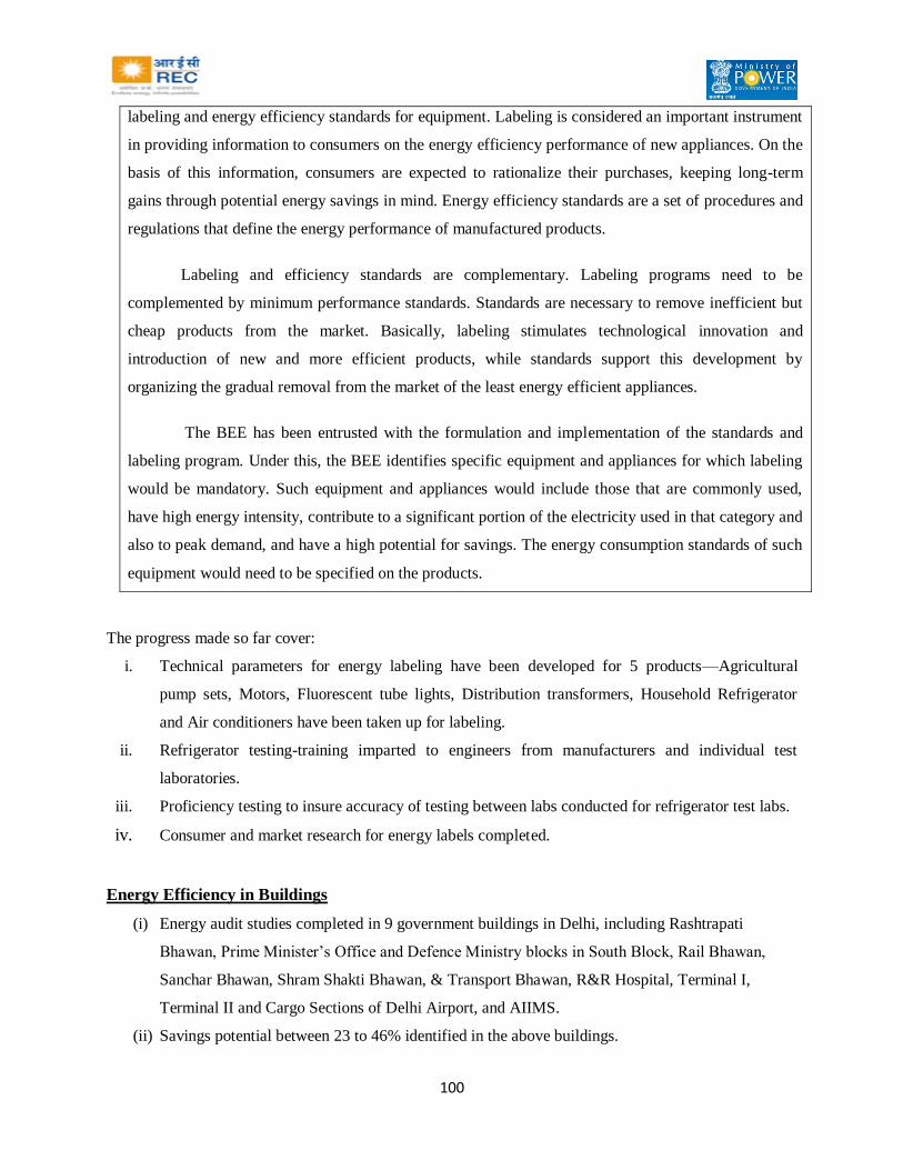
100
labeling and energy efficiency standards for equipment. Labeling is considered an important instrument
in providing information to consumers on the energy efficiency performance of new appliances. On the
basis of this information, consumers are expected to rationalize their purchases, keeping long-term
gains through potential energy savings in mind. Energy efficiency standards are a set of procedures and
regulations that define the energy performance of manufactured products.
Labeling and efficiency standards are complementary. Labeling programs need to be
complemented by minimum performance standards. Standards are necessary to remove inefficient but
cheap products from the market. Basically, labeling stimulates technological innovation and
introduction of new and more efficient products, while standards support this development by
organizing the gradual removal from the market of the least energy efficient appliances.
The BEE has been entrusted with the formulation and implementation of the standards and
labeling program. Under this, the BEE identifies specific equipment and appliances for which labeling
would be mandatory. Such equipment and appliances would include those that are commonly used,
have high energy intensity, contribute to a significant portion of the electricity used in that category and
also to peak demand, and have a high potential for savings. The energy consumption standards of such
equipment would need to be specified on the products.
The progress made so far cover:
i. Technical parameters for energy labeling have been developed for 5 products—Agricultural
pump sets, Motors, Fluorescent tube lights, Distribution transformers, Household Refrigerator
and Air conditioners have been taken up for labeling.
ii. Refrigerator testing-training imparted to engineers from manufacturers and individual test
laboratories.
iii. Proficiency testing to insure accuracy of testing between labs conducted for refrigerator test labs.
iv. Consumer and market research for energy labels completed.
Energy Efficiency in Buildings
(i) Energy audit studies completed in 9 government buildings in Delhi, including Rashtrapati
Bhawan, Prime Minister’s Office and Defence Ministry blocks in South Block, Rail Bhawan,
Sanchar Bhawan, Shram Shakti Bhawan, & Transport Bhawan, R&R Hospital, Terminal I,
Terminal II and Cargo Sections of Delhi Airport, and AIIMS.
(ii) Savings potential between 23 to 46% identified in the above buildings.

101
(iii) Implementation of energy audit studies to be done through energy service companies (ESCO).
A consortium of energy auditors was formed and energy service companies (ESCOs) were
introduced to conduct energy audit studies..
ENERGY CONSERVATION BUILDING CODES
The new buildings are required to be designed and built with energy efficiency consideration
right from the initial stages itself. The development of energy conservation building codes is necessary for
this purpose. The codes would be applicable to commercial buildings constructed after the relevant rules
are notified under the Energy Conservation Act. The codes would be prepared for different climatic
zones.
DSM
The BEE action plan at its website suggests that the power distribution utilities should have DSM
cells (to implement the DSM programs). The BEE seems to imply utility-sponsored efficiency programs
as a meaning of DSM. Under the Energy Conservation Act, 2001, the union government, in consultation
with the BEE, may specify any “designated consumer” to switch to energy-efficient equipment.
According to the schedule of the act, power utilities such as electricity distribution companies are
also recognized as designated consumers and hence, DSM is applicable to them.
So far, very little has been done by BEE related to DSM. Typical MoUs by MoP required the
state governments / utilities to undertake DSM activities. The typical provision reads as follows:
“An effective program in the field of demand side management through – energy efficient bulbs,
tube lights and agricultural pump-sets. Time of the day metering and differential tariff for peak and off
peak hours needs to be implemented with suitable mass awareness and extension efforts.” In summary,
the GoI has accorded priority to energy conservation including DSM and initiated several actions to
facilitate and ensure its implementation.
One of the first DSM programs in India was undertaken by the Ahmedabad Electricity Company
(AEC) with USAID assistance under the ECO project was to set up a DSM cell in 1994. The cell has
worked with customers to develop load research data, screen alternative energy-efficiency measures and
implement some of those measures through the involvement of energy service companies. Two ESCOs
worked with AEC to implement efficient lighting and reactive power compensation measures (through
capacitor installations) at its HT and LT customer premises. This has led to peak load savings of about 10
per cent, thereby reducing the need for expensive imported power during peak load hours. Utility-driven

102
DSM has started gaining importance only recently. DSM cells have been established by the Tamil Nadu
Electricity Board and by the Jaipur discom. These cells are focusing on specific functional areas such as
marketing and data analysis. The USAID under its Energy Conservation and Commercialization (ECO)
Project has taken up DSM initiatives at the Jaipur discom. The government is laying emphasis on self-
regulation and market-based mechanisms for promoting efficient use of energy. It is focusing on capacity
building and setting standards for energy efficiency in equipment and buildings. It is promoting energy
auditing and appointment of energy managers.
Energy Conservation in Schools and general public
BEE is also making an effort to increase awareness about energy conservation among students
through the school curriculum. At a macro level, energy conservation requires a paradigm shift from a
supply-dominated approach to an integrated approach, incorporating a judicious mix of investment in
capacity, improvement in operational efficiency of existing power stations, reduction in T&D losses, end-
user efficiency and renewable technology. A few organizations are taking up mass education campaigns
in the industrial townships. These events are religiously organized on the energy conservation day, 14
December every year.
State Nodal Agencies
So far 18 states have notified designated agencies to coordinate, regulate and enforce the
provisions of the Energy Conservation Act, 2001. Most states have entrusted the task of initiating energy
conservation programs to the renewable energy development agencies. While a number of designated
agencies are still working out the program details, some have begun implementing them. On the top of
their agenda is spreading awareness on the usefulness of energy conservation.


![NATIONAL TRAINING PROGRAM FOR C & D …bescom.org/wp-content/uploads/2015/03/new-version-Variant-IV1.pdf[Type text] NATIONAL TRAINING PROGRAM FOR C & D EMPLOYEES Financial Management,](https://img.pdfslide.us/doc/110x75/5abd7edc7f8b9a7e418bb47c/national-training-program-for-c-d-type-text-national-training-program-for-c.jpg)
![CITY OF DETROIT, MI · 2019. 8. 19. · mbc 713.4 mbc 1023.2 mbc 1024.3 mbc 713.4 mbc 3005.4 b all 1 (0 @ fourth floor) [mbc table 1020.1] means of egress: doors : the minimum clear](https://img.pdfslide.us/doc/110x75/60ed05e7f54aa77ae433b479/city-of-detroit-mi-2019-8-19-mbc-7134-mbc-10232-mbc-10243-mbc-7134-mbc.jpg)