Embed Size (px)
Citation preview
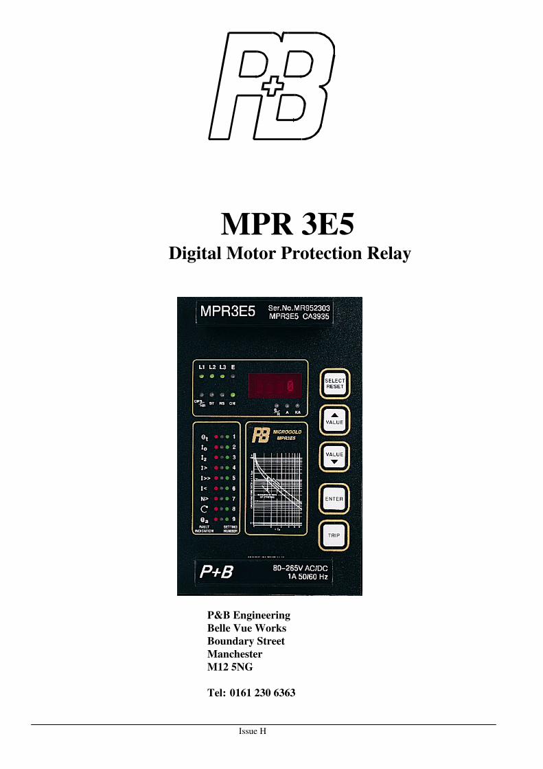
Issue H
MPR 3E5 Digital Motor Protection Relay
P&B Engineering
Belle Vue Works
Boundary Street
Manchester
M12 5NG
Tel: 0161 230 6363
Issue H
Fax: 0161 230 6464
E-mail [email protected]
Contents
CONTENTS ..................................................................................................................................................................... I
1. INTRODUCTION...................................................................................................................................................... 2
2. APPLICATION.......................................................................................................................................................... 3
3. FEATURES AND CHARACTERISTICS ............................................................................................................... 3
4. DESIGN ...................................................................................................................................................................... 4
4.1 CIRCUIT DIAGRAMS ................................................................................................................................................ 4 4.1.1 Analogue input circuits ................................................................................................................................... 5
4.1.2 Output relays................................................................................................................................................... 5
4.1.3Remote data communication............................................................................................................................ 5
5. FRONT PANEL......................................................................................................................................................... 6
5.1 ALPHANUMERIC DISPLAY ....................................................................................................................................... 6 5.1.2. Mode 2 Settings.............................................................................................................................................. 8
5.1.3. Fault indication ............................................................................................................................................. 9
5.2. LED indicators.................................................................................................................................................. 9
5.3. Push buttons...................................................................................................................................................... 9
6. WORKING PRINCIPLES...................................................................................................................................... 10
6.1 ANALOGUE CIRCUITS ............................................................................................................................................ 10 6.2 DIGITAL CIRCUITS ................................................................................................................................................. 10
7. OPERATION AND SETTING ............................................................................................................................... 11
7.1 LAYOUT OF THE CONTROL ELEMENTS ................................................................................................................... 11 7.2. RELAY DISPLAY AND SETTING PROCEDURE. ........................................................................................................ 11
7.2.1. Display mode(1)........................................................................................................................................... 11
7.2.2. Setting Mode (2)........................................................................................................................................... 11
7.3 SETTING PROCEDURE ............................................................................................................................................ 13 7.3.1. t6x Setting .................................................................................................................................................... 13
7.3.2. Speed Switch ................................................................................................................................................ 13
7.3.3. Full Load Current Setting I FLC ................................................................................................................ 13
7.3.4. CT Primary Setting ...................................................................................................................................... 13
7.3.5. Hot/Cold Ratio Setting................................................................................................................................. 14
7.3.6. Thermal Overload Pre-Alarm Setting.......................................................................................................... 14
7.3.7. Number of Starts per Hour. ......................................................................................................................... 14
7.3.8. Start Inhibit Time ......................................................................................................................................... 14
7.3.9. Earth Fault Current ..................................................................................................................................... 14
7.3.10. Earth Fault trip Time................................................................................................................................. 15
7.3.11. Unbalance Current .................................................................................................................................... 15
7.3.12. Undercurrent Setting ................................................................................................................................. 16
7.3.13. Undercurrent Time..................................................................................................................................... 16
7.3.14. High Set Overcurrent................................................................................................................................. 16
7.3.15. High Set Overcurrent Time........................................................................................................................ 16
7.3.16 Low Set Overcurrent ................................................................................................................................... 16
7.3.17 Low Set Overcurrent Time .......................................................................................................................... 16
7.3.19 Set Password............................................................................................................................................... 16
7.3.20 Serial Link Address, RSnn........................................................................................................................... 16
Issue H
7.4 MATRIX SETTING .................................................................................................................................................. 17 7.4.1 Trip Relay Matrix, Tnnn ............................................................................................................................... 17
7.4.2 Programmable Relay Matrix, Pnnn .............................................................................................................. 17
7.4.3 Alarm Relay Matrix, Annn ............................................................................................................................ 18
7.4.4 Earth fault parameters Matrix, Ennn............................................................................................................ 18
7.4.5 Trip/ Reset Matrix, Rnnn.............................................................................................................................. 19
7.4.6 Thermal O/L Matrix, Cnnn ......................................................................................................................... 19
7.4.7 Speed switch Matrix, Snnn........................................................................................................................... 20
7.4.8 Advanced relay Matrix, Xnnn ....................................................................................................................... 20
7.5. DIP SWITCH SETTINGS......................................................................................................................................... 22 7.6. TEST TRIP ............................................................................................................................................................ 23 7.7. RESET .................................................................................................................................................................. 23
7.7.1 Hand reset..................................................................................................................................................... 23
7.7.2 Auto-reset at Power Up ................................................................................................................................ 23
7.8. PHASE ROTATION................................................................................................................................................. 23 7.9. SETTING VALUE CALCULATION............................................................................................................................. 23
8. RELAY CASE.......................................................................................................................................................... 24
8.1 INDIVIDUAL CASE.................................................................................................................................................. 24 8.2 RACK MOUNTING .................................................................................................................................................. 24 8.3 TERMINAL CONNECTIONS...................................................................................................................................... 24
9. COMMISSIONING AND TESTING THE MPR3E5........................................................................................... 24
9.1. COMMISSIONING. ................................................................................................................................................. 24 9.2. TESTING. .............................................................................................................................................................. 25
10. TECHNICAL DATA ............................................................................................................................................. 28
10.1 MEASURING INPUT CIRCUITS .............................................................................................................................. 28 10.2 AUXILIARY POWER SUPPLY ................................................................................................................................. 28 10.3 COMMON DATA................................................................................................................................................... 28 10.4 TOLERANCES .................................................................................................................................................. 29 10.6 OUTPUT CONTACT RATINGS ................................................................................................................................ 31 10.7 SYSTEM DATA ..................................................................................................................................................... 31 10.8 HOUSING............................................................................................................................................................. 32 10.9 CONNECTION DETAILS ........................................................................................................................................ 33
11. ORDER FORM...................................................................................................................................................... 34
14/1/98 Page 2 Issue H
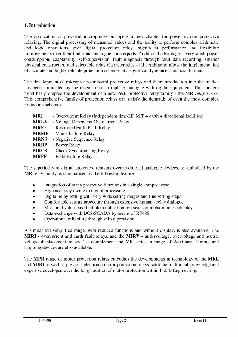
1. Introduction
The application of powerful microprocessors opens a new chapter for power system protective relaying. The digital processing of measured values and the ability to perform complex arithmetic and logic operations, give digital protection relays significant performance and flexibility improvements over their traditional analogue counterparts. Additional advantages - very small power consumption, adaptability, self-supervision, fault diagnosis through fault data recording, smaller physical construction and selectable relay characteristics - all combine to allow the implementation of accurate and highly reliable protection schemes at a significantly reduced financial burden. The development of microprocessor based protective relays and their introduction into the market has been stimulated by the recent trend to replace analogue with digital equipment. This modern
trend has prompted the development of a new P&B protective relay family - the MR relay series. This comprehensive family of protection relays can satisfy the demands of even the most complex protection schemes:
MRI - Overcurrent Relay (Independent time/I.D.M.T + earth + directional facilities)
MRI-V - Voltage Dependent Overcurrent Relay
MREF - Restricted Earth Fault Relay
MRMF - Mains Failure Relay
MRNS - Negative Sequence Relay
MRRP - Power Relay
MRCS - Check Synchronising Relay
MRFF - Field Failure Relay The superiority of digital protective relaying over traditional analogue devices, as embodied by the
MR relay family, is summarised by the following features:
•••• Integration of many protective functions in a single compact case •••• High accuracy owing to digital processing •••• Digital relay setting with very wide setting ranges and fine setting steps •••• Comfortable setting procedure through extensive human - relay dialogue •••• Measured values and fault data indication by means of alpha-numeric display •••• Data exchange with DCS/SCADA by means of RS485 •••• Operational reliability through self-supervision
A similar but simplified range, with reduced functions and without display, is also available. The
MIRI - overcurrent and earth fault relays, and the MIRV - undervoltage, overvoltage and neutral voltage displacement relays. To complement the MR series, a range of Auxiliary, Timing and Tripping devices are also available.
The MPR range of motor protection relays embodies the developments in technology of the MRI,
and MIRI as well as previous electronic motor protection relays, with the traditional knowledge and expertise developed over the long tradition of motor protection within P & B Engineering.
14/1/98 Page 3 Issue H
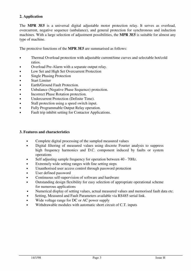
2. Application
The MPR 3E5 is a universal digital adjustable motor protection relay. It serves as overload, overcurrent, negative sequence (unbalance), and general protection for synchronous and induction
machines. With a large selection of adjustment possibilities, the MPR 3E5 is suitable for almost any type of machine.
The protective functions of the MPR 3E5 are summarised as follows:
• Thermal Overload protection with adjustable current/time curves and selectable hot/cold ratios. • Overload Pre-Alarm with a separate output relay. • Low Set and High Set Overcurrent Protection • Single Phasing Protection • Start Limiter • Earth/Ground Fault Protection. • Unbalance (Negative Phase Sequence) protection. • Incorrect Phase Rotation protection. • Undercurrent Protection (Definite Time). • Stall protection using a speed switch input. • Fully Programmable Output Relay operation. • Fault trip inhibit setting for Contactor Applications.
3. Features and characteristics
• Complete digital processing of the sampled measured values • Digital filtering of measured values using discrete Fourier analysis to suppress
high frequency harmonics and D.C. component induced by faults or system operations
• Self adjusting sample frequency for operation between 40 - 70Hz. • Extremely wide setting ranges with fine setting steps • Unauthorised user access control through password protection • User defined password • Continuous self-supervision of software and hardware • Outstanding design flexibility for easy selection of appropriate operational scheme
for numerous applications • Numerical display of setting values, actual measured values and memorised fault data etc. • Setting, Measured and Fault Parameters available via RS485 serial link. • Wide voltage range for DC or AC power supply • Withdrawable modules with automatic short circuit of C.T. inputs
14/1/98 Page 4 Issue H
4. Design
4.1 Circuit Diagrams
18
POWER
SUPPLY
1 2 CASE
Supply
MPR 3E5
Typical Earthing Shown
TRIP SIGNAL7
5
3
6
48
1014
12
+
171516
Gnd-
913
11
PROGRAMMABLE
ALARM
RS485
21
22
23
24
25
26
27
28
L1
L2
L3
I1
I2
I3
IE
S2P2
P1
S1
CHASSIS
EARTH
19
20
SPEED SWITCH
IE
27
28
CBCT
Alternative E/F connectionfor CBT
Rstab
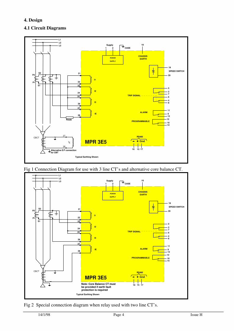
Fig 1 Connection Diagram for use with 3 line CT’s and alternative core balance CT.
18
POWER
SUPPLY
1 2 CASE
Supply
MPR 3E5
Typical Earthing Shown
7
5
3
6
48
1014
12
+
171516
Gnd-
913
11
RS485
21
22
23
24
25
26
27
28
L1
L2
L3
I1
I2
I3
IE
S2P2
P1
S1
CHASSIS
EARTH
19
20
SPEED SWITCH
CBCT
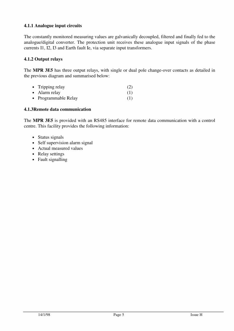
Note: Core Balance CT mustbe provided if earth faultprotection is required
TRIP SIGNAL
PROGRAMMABLE
ALARM
Fig 2 Special connection diagram when relay used with two line CT’s.
14/1/98 Page 5 Issue H
4.1.1 Analogue input circuits
The constantly monitored measuring values are galvanically decoupled, filtered and finally fed to the analogue/digital converter. The protection unit receives these analogue input signals of the phase currents I1, I2, I3 and Earth fault Ie, via separate input transformers.
4.1.2 Output relays
The MPR 3E5 has three output relays, with single or dual pole change-over contacts as detailed in the previous diagram and summarised below:
• Tripping relay (2) • Alarm relay (1) • Programmable Relay (1)
4.1.3Remote data communication
The MPR 3E5 is provided with an RS485 interface for remote data communication with a control centre. This facility provides the following information:
• Status signals • Self supervision alarm signal • Actual measured values • Relay settings • Fault signalling
14/1/98 Page 6 Issue H
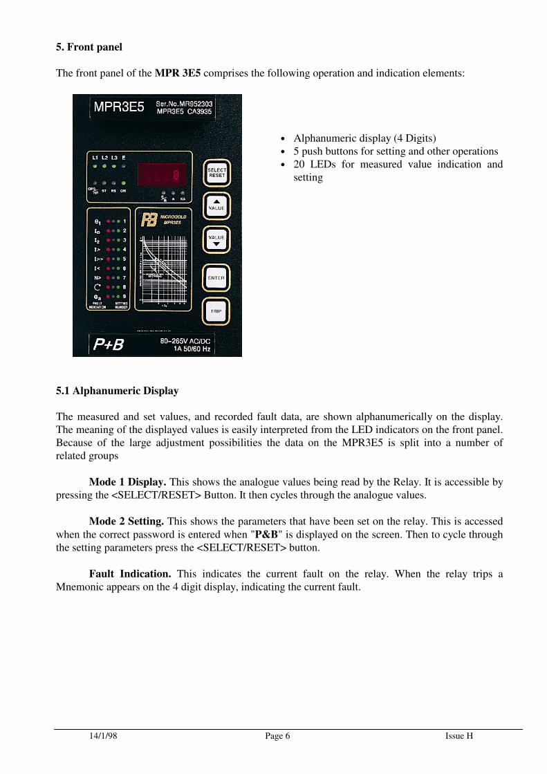
5. Front panel
The front panel of the MPR 3E5 comprises the following operation and indication elements:
• Alphanumeric display (4 Digits) • 5 push buttons for setting and other operations • 20 LEDs for measured value indication and
setting
5.1 Alphanumeric Display
The measured and set values, and recorded fault data, are shown alphanumerically on the display. The meaning of the displayed values is easily interpreted from the LED indicators on the front panel. Because of the large adjustment possibilities the data on the MPR3E5 is split into a number of related groups
Mode 1 Display. This shows the analogue values being read by the Relay. It is accessible by pressing the <SELECT/RESET> Button. It then cycles through the analogue values.
Mode 2 Setting. This shows the parameters that have been set on the relay. This is accessed
when the correct password is entered when "P&B" is displayed on the screen. Then to cycle through the setting parameters press the <SELECT/RESET> button.
Fault Indication. This indicates the current fault on the relay. When the relay trips a Mnemonic appears on the 4 digit display, indicating the current fault.
14/1/98 Page 7 Issue H
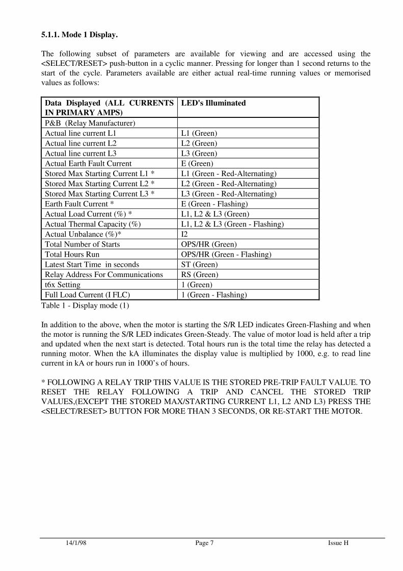
5.1.1. Mode 1 Display.
The following subset of parameters are available for viewing and are accessed using the <SELECT/RESET> push-button in a cyclic manner. Pressing for longer than 1 second returns to the start of the cycle. Parameters available are either actual real-time running values or memorised values as follows:
Data Displayed (ALL CURRENTS
IN PRIMARY AMPS)
LED's Illuminated
P&B (Relay Manufacturer)
Actual line current L1 L1 (Green)
Actual line current L2 L2 (Green)
Actual line current L3 L3 (Green)
Actual Earth Fault Current E (Green)
Stored Max Starting Current L1 * L1 (Green - Red-Alternating)
Stored Max Starting Current L2 * L2 (Green - Red-Alternating)
Stored Max Starting Current L3 * L3 (Green - Red-Alternating)
Earth Fault Current * E (Green - Flashing)
Actual Load Current (%) * L1, L2 & L3 (Green)
Actual Thermal Capacity (%) L1, L2 & L3 (Green - Flashing)
Actual Unbalance (%)* I2
Total Number of Starts OPS/HR (Green)
Total Hours Run OPS/HR (Green - Flashing)
Latest Start Time in seconds ST (Green)
Relay Address For Communications RS (Green)
t6x Setting 1 (Green)
Full Load Current (I FLC) 1 (Green - Flashing)
Table 1 - Display mode (1) In addition to the above, when the motor is starting the S/R LED indicates Green-Flashing and when the motor is running the S/R LED indicates Green-Steady. The value of motor load is held after a trip and updated when the next start is detected. Total hours run is the total time the relay has detected a running motor. When the kA illuminates the display value is multiplied by 1000, e.g. to read line current in kA or hours run in 1000’s of hours. * FOLLOWING A RELAY TRIP THIS VALUE IS THE STORED PRE-TRIP FAULT VALUE. TO RESET THE RELAY FOLLOWING A TRIP AND CANCEL THE STORED TRIP VALUES,(EXCEPT THE STORED MAX/STARTING CURRENT L1, L2 AND L3) PRESS THE <SELECT/RESET> BUTTON FOR MORE THAN 3 SECONDS, OR RE-START THE MOTOR.
14/1/98 Page 8 Issue H
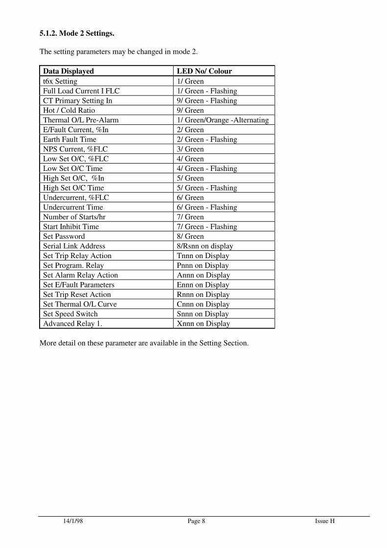
5.1.2. Mode 2 Settings.
The setting parameters may be changed in mode 2.
Data Displayed LED No/ Colour
t6x Setting 1/ Green
Full Load Current I FLC 1/ Green - Flashing
CT Primary Setting In 9/ Green - Flashing
Hot / Cold Ratio 9/ Green
Thermal O/L Pre-Alarm 1/ Green/Orange -Alternating
E/Fault Current, %In 2/ Green
Earth Fault Time 2/ Green - Flashing
NPS Current, %FLC 3/ Green
Low Set O/C, %FLC 4/ Green
Low Set O/C Time 4/ Green - Flashing
High Set O/C, %In 5/ Green
High Set O/C Time 5/ Green - Flashing
Undercurrent, %FLC 6/ Green
Undercurrent Time 6/ Green - Flashing
Number of Starts/hr 7/ Green
Start Inhibit Time 7/ Green - Flashing
Set Password 8/ Green
Serial Link Address 8/Rsnn on display
Set Trip Relay Action Tnnn on Display
Set Program. Relay Pnnn on Display
Set Alarm Relay Action Annn on Display
Set E/Fault Parameters Ennn on Display
Set Trip Reset Action Rnnn on Display
Set Thermal O/L Curve Cnnn on Display
Set Speed Switch Snnn on Display
Advanced Relay 1. Xnnn on Display
More detail on these parameter are available in the Setting Section.

14/1/98 Page 9 Issue H
5.1.3. Fault indication
When the relay has tripped, the display will show "TRIP" and the relevant LED will be illuminated red. On cycling through the displays in Mode 1, a four letter mnemonic describing the trip will be displayed. The mnemonics are listed in the table below.
Trip Mnemonic
Overload OVLD
Earth Fault EFLT
High Set Overcurrent HSOC
Low Set Overcurrent LSOC
Unbalance NPSC
Undercurrent UCUR
Too Many Starts STLM
Phase Reversal ROTN
Stalled STLD
Single Phasing SPHA
Should an internal fault occur causing the relay to alarm, then the mnemonic "IRF" followed by a
number will be displayed. If this occurs, or any other indication such as "UDEF" then the indication/number should be noted and reported to the P&B Engineering office ( +44 161 230 6363).
5.2. LED indicators
The LEDs to the left of the display indicate measuring or tripping values. The purpose of the corresponding LED is identified by the adjacent inscription.
The first row of four LEDs to the left of the display are tri-coloured, green and yellow indicate measuring and red indicates a fault condition. The LED marked RS indicates active serial data communication. The rest of the LEDs are used when accessing Mode 1 and Mode 2 of the Display.
5.3. Push buttons
The front panel contains five push buttons used for setting, measuring and other user functions.
The individual setting and measuring values can be selected in turn by pressing the <SELECT> /
<RESET> push button. This button also resets the relay if pressed for approximately 3 seconds.
The <UP> and <DOWN> push buttons are for incrementing and decrementing any selected parameter. Continuous pressing of these push buttons will cause the parameter to change at an increased rate.
The <ENTER> push button is used to transfer the indicated value to the internal parameter memory. An unintended or unauthorised change of the selected parameter can be avoided through the password protection facility.
The <TRIP> push button is used to test the output relay circuits, both for tripping and signalling. This operation is also password protected.
14/1/98 Page 10 Issue H
6. Working principles
6.1 Analogue circuits
The incoming currents and voltages from the external transformers are converted to internal signals in proportion to the current and voltage, via the internal input transducers and shunt resistors. The noise signals caused by inductive and capacitive coupling are suppressed by an analogue RC filter circuit. The analogue signals are fed to the A/D converter of the micro-processor and transformed to digital signals through sample-hold circuits. The analogue signals are sampled at a rate of 16 times the system frequency (40 - 70Hz), giving a sample time of 1.56 - 0.9mS for each measured value.
6.2 Digital circuits
The essential component of the MPR 3E5 relay is a powerful micro-controller. All of the operations, from the analogue digital conversion to the relay trip decision, are carried out by the micro-controller digitally. The relay program, located in EPROM, allows the CPU of the micro-controller to calculate the reactance values in order to detect a possible fault.
For the calculation of the current values, an efficient digital filter, based on the Fourier Analysis (DFFT - Discrete Fast Fourier Transformation), is applied to suppress high frequency harmonics and DC components caused by fault induced transients or other system disturbances. The actual calculated values are compared with the relay settings. When a value exceeds the starting value the unit starts the corresponding time delay calculation. When the set time delay has elapsed, a trip signal is given.
The relay setting values for all parameters are stored in EEPROM, so that the actual relay settings cannot be lost, even in the event of auxiliary supply interruption. The micro-processor is supervised through a built in "Watch-dog" timer. Should a failure occur the watch-dog timer resets the micro-processor and gives an alarm signal via the self supervision output relay.
14/1/98 Page 11 Issue H
7. Operation and Setting
7.1 Layout of the control elements
All control elements required for the operation and adjustment of the MPR 3E5 are located on the front panel. They are divided according to function into the three following groups:
• Alphanumeric Display: Indication of parameter set values, actual measured values and recorded fault data. • LED's: Indication of selected parameters and measured quantities. • Push Buttons: Selection of parameter to be adjusted, quantity to be measured and adjustment of parameter values. Where;
<SELECT / RESET> Selection of the parameter to be set and the relay quantities to be measured. Press for 3 seconds to reset.
<UP> Increment of the setting values for the parameter selected.
<DOWN> Decrement of the setting values for the parameter selected.
<ENTER> Storage of the setting values for the selected parameter.
<TRIP> Testing of the output relay circuits.
With the front cover in place, it is only possible to press the <SELECT/RESET>
push button. this allows display of parameters or a relay reset following a trip. Should the cover be
opened, the <UP>, <DOWN>, <ENTER> and <TRIP> , buttons are inactive and it is not possible to alter the protection settings without putting the relay into the setting mode(2), which requires entry
of a password. By pressing the <SELECT/RESET> push button, it is possible to step through the parameters. The corresponding LED illuminates, and the measured or present set value of the selected parameter is indicated on the display. This set value may then be increased or decreased by
pressing the <UP> or <DOWN> buttons respectively. The selected set value is only stored after
pressing the <ENTER> push button and inputting the correct password. This means that adjustment of the unit is only possible by authorised users. In addition by pressing the button for 3 seconds or more the relay may be reset after a trip, providing the thermal capacity has reduced to a value sufficient to enable a restart.
7.2. Relay Display and Setting Procedure.
7.2.1. Display mode(1)
In this subset of parameters the data is for viewing and are accessed using the <SELECT/RESET> push-button in a cyclic manner. Pressing for longer than 1 second returns to the start of the cycle.
7.2.2. Setting Mode (2)
In order to enter this mode the user must be in display mode (1), by use of the <SELECT/RESET>
Push button move through the indications until “P&B” is shown on the display, then enter the correct
password ( default “∧∧∧∧∧∧∧∧∧∧∧∧∧∧∧∧“). When the password is entered correctly, the display shows “∂∂∂∂“ with the accents flashing to confirm relay is in setting mode. In order to change the setting in mode(2),
cycle through the setting parameters by pressing the <SELECT/RESET> button until the required
parameter is reached. Then increase or decrease the setting by using the <^ VALUE> or <∨∨∨∨
VALUE> buttons followed by <ENTER> to store the new value. To return quickly to the start of
the cycle i.e. the t6x setting, press the <SELECT/RESET> key for longer than 1 second. To return
14/1/98 Page 12 Issue H
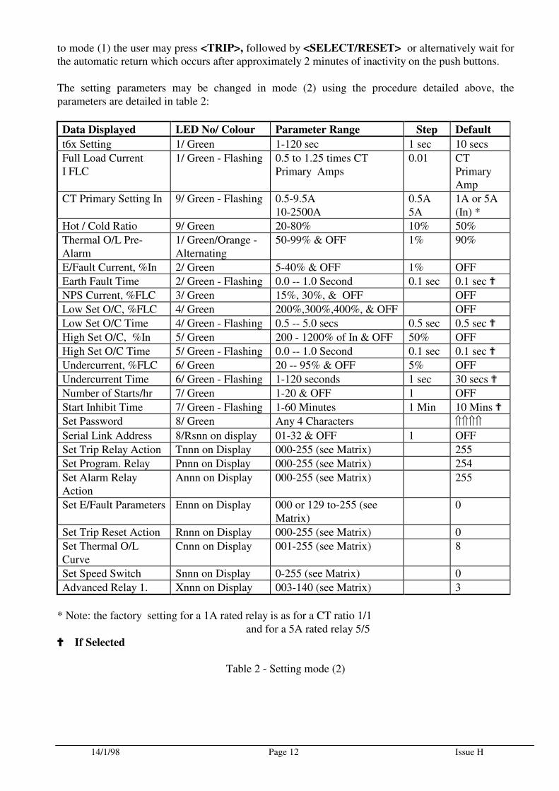
to mode (1) the user may press <TRIP>, followed by <SELECT/RESET> or alternatively wait for the automatic return which occurs after approximately 2 minutes of inactivity on the push buttons. The setting parameters may be changed in mode (2) using the procedure detailed above, the parameters are detailed in table 2:
Data Displayed LED No/ Colour Parameter Range Step Default
t6x Setting 1/ Green 1-120 sec 1 sec 10 secs
Full Load Current I FLC
1/ Green - Flashing 0.5 to 1.25 times CT Primary Amps
0.01 CT Primary Amp
CT Primary Setting In 9/ Green - Flashing 0.5-9.5A 10-2500A
0.5A 5A
1A or 5A (In) *
Hot / Cold Ratio 9/ Green 20-80% 10% 50%
Thermal O/L Pre-Alarm
1/ Green/Orange -Alternating
50-99% & OFF 1% 90%
E/Fault Current, %In 2/ Green 5-40% & OFF 1% OFF
Earth Fault Time 2/ Green - Flashing 0.0 -- 1.0 Second 0.1 sec 0.1 sec
NPS Current, %FLC 3/ Green 15%, 30%, & OFF OFF
Low Set O/C, %FLC 4/ Green 200%,300%,400%, & OFF OFF
Low Set O/C Time 4/ Green - Flashing 0.5 -- 5.0 secs 0.5 sec 0.5 sec
High Set O/C, %In 5/ Green 200 - 1200% of In & OFF 50% OFF
High Set O/C Time 5/ Green - Flashing 0.0 -- 1.0 Second 0.1 sec 0.1 sec
Undercurrent, %FLC 6/ Green 20 -- 95% & OFF 5% OFF
Undercurrent Time 6/ Green - Flashing 1-120 seconds 1 sec 30 secs
Number of Starts/hr 7/ Green 1-20 & OFF 1 OFF
Start Inhibit Time 7/ Green - Flashing 1-60 Minutes 1 Min 10 Mins
Set Password 8/ Green Any 4 Characters ⇑⇑⇑⇑
Serial Link Address 8/Rsnn on display 01-32 & OFF 1 OFF
Set Trip Relay Action Tnnn on Display 000-255 (see Matrix) 255
Set Program. Relay Pnnn on Display 000-255 (see Matrix) 254
Set Alarm Relay Action
Annn on Display 000-255 (see Matrix) 255
Set E/Fault Parameters Ennn on Display 000 or 129 to-255 (see Matrix)
0
Set Trip Reset Action Rnnn on Display 000-255 (see Matrix) 0
Set Thermal O/L Curve
Cnnn on Display 001-255 (see Matrix) 8
Set Speed Switch Snnn on Display 0-255 (see Matrix) 0
Advanced Relay 1. Xnnn on Display 003-140 (see Matrix) 3
* Note: the factory setting for a 1A rated relay is as for a CT ratio 1/1 and for a 5A rated relay 5/5
If Selected
Table 2 - Setting mode (2)
14/1/98 Page 13 Issue H
7.3 Setting procedure
In the following sections the setting of all relay parameters is described in detail:
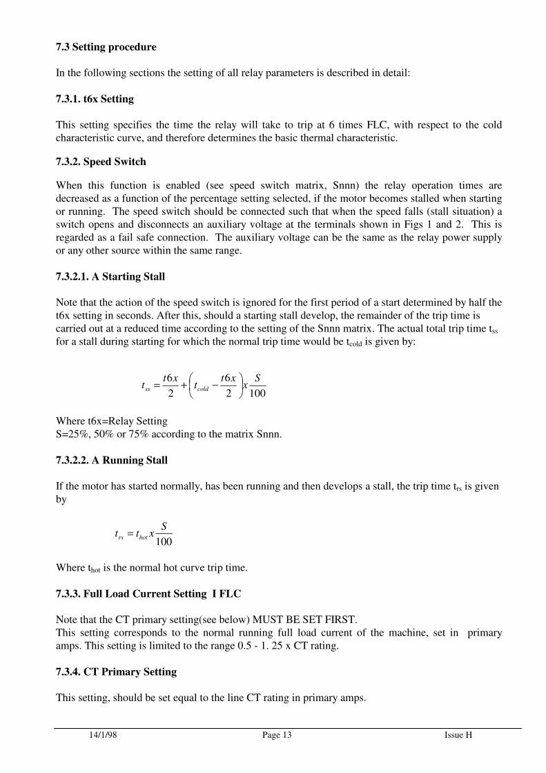
7.3.1. t6x Setting
This setting specifies the time the relay will take to trip at 6 times FLC, with respect to the cold characteristic curve, and therefore determines the basic thermal characteristic.
7.3.2. Speed Switch
When this function is enabled (see speed switch matrix, Snnn) the relay operation times are decreased as a function of the percentage setting selected, if the motor becomes stalled when starting or running. The speed switch should be connected such that when the speed falls (stall situation) a switch opens and disconnects an auxiliary voltage at the terminals shown in Figs 1 and 2. This is regarded as a fail safe connection. The auxiliary voltage can be the same as the relay power supply or any other source within the same range.
7.3.2.1. A Starting Stall
Note that the action of the speed switch is ignored for the first period of a start determined by half the t6x setting in seconds. After this, should a starting stall develop, the remainder of the trip time is carried out at a reduced time according to the setting of the Snnn matrix. The actual total trip time tss for a stall during starting for which the normal trip time would be tcold is given by:
Where t6x=Relay Setting S=25%, 50% or 75% according to the matrix Snnn.
7.3.2.2. A Running Stall
If the motor has started normally, has been running and then develops a stall, the trip time trs is given by
Where thot is the normal hot curve trip time.
7.3.3. Full Load Current Setting I FLC
Note that the CT primary setting(see below) MUST BE SET FIRST. This setting corresponds to the normal running full load current of the machine, set in primary amps. This setting is limited to the range 0.5 - 1. 25 x CT rating.
7.3.4. CT Primary Setting
This setting, should be set equal to the line CT rating in primary amps.
1002
6
2
6 Sx
xtt
xtt coldss
−+=
100
Sxtt hotrs =
14/1/98 Page 14 Issue H
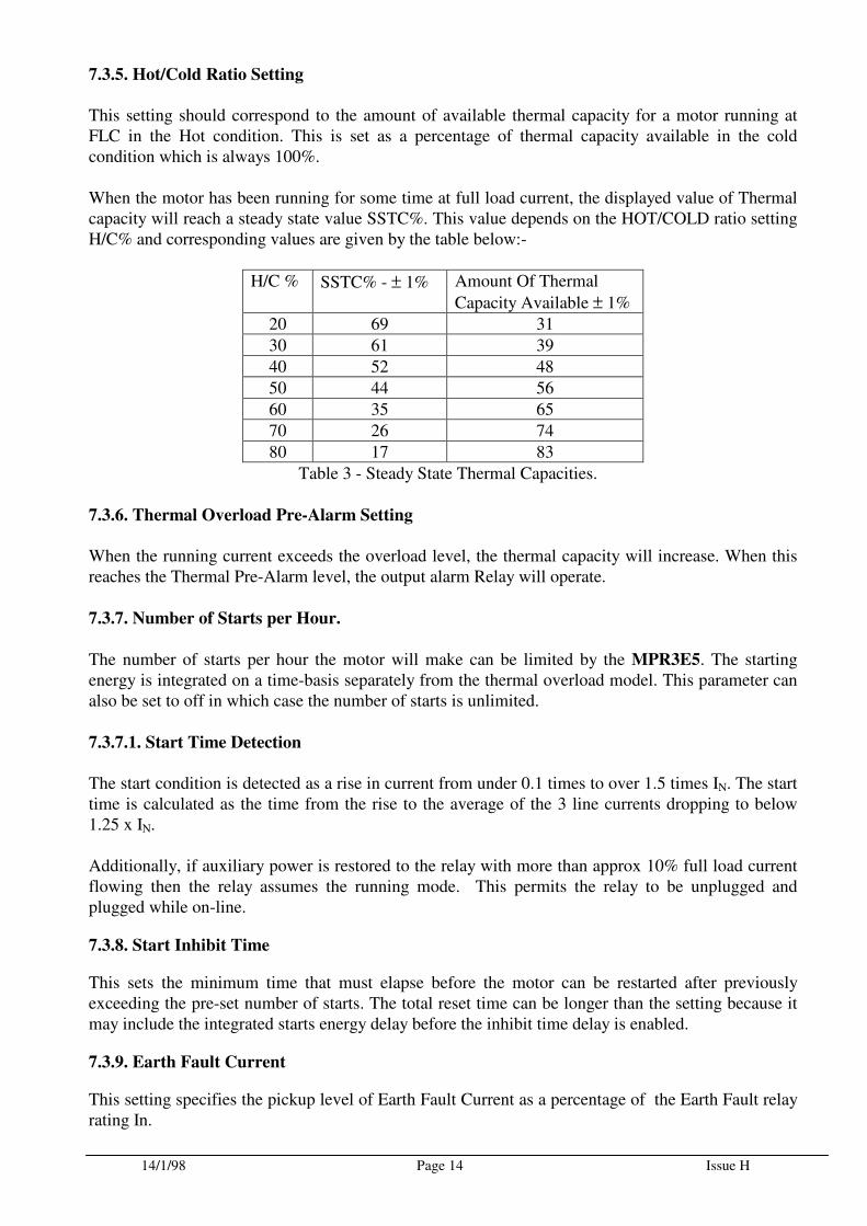
7.3.5. Hot/Cold Ratio Setting
This setting should correspond to the amount of available thermal capacity for a motor running at FLC in the Hot condition. This is set as a percentage of thermal capacity available in the cold condition which is always 100%. When the motor has been running for some time at full load current, the displayed value of Thermal capacity will reach a steady state value SSTC%. This value depends on the HOT/COLD ratio setting H/C% and corresponding values are given by the table below:-
H/C % SSTC% - ± 1% Amount Of Thermal
Capacity Available ± 1%
20 69 31
30 61 39
40 52 48
50 44 56
60 35 65
70 26 74
80 17 83
Table 3 - Steady State Thermal Capacities.
7.3.6. Thermal Overload Pre-Alarm Setting
When the running current exceeds the overload level, the thermal capacity will increase. When this reaches the Thermal Pre-Alarm level, the output alarm Relay will operate.
7.3.7. Number of Starts per Hour.
The number of starts per hour the motor will make can be limited by the MPR3E5. The starting energy is integrated on a time-basis separately from the thermal overload model. This parameter can also be set to off in which case the number of starts is unlimited.
7.3.7.1. Start Time Detection
The start condition is detected as a rise in current from under 0.1 times to over 1.5 times IN. The start time is calculated as the time from the rise to the average of the 3 line currents dropping to below 1.25 x IN.
Additionally, if auxiliary power is restored to the relay with more than approx 10% full load current flowing then the relay assumes the running mode. This permits the relay to be unplugged and plugged while on-line.
7.3.8. Start Inhibit Time
This sets the minimum time that must elapse before the motor can be restarted after previously exceeding the pre-set number of starts. The total reset time can be longer than the setting because it may include the integrated starts energy delay before the inhibit time delay is enabled.
7.3.9. Earth Fault Current
This setting specifies the pickup level of Earth Fault Current as a percentage of the Earth Fault relay rating In.
14/1/98 Page 15 Issue H
7.3.10. Earth Fault trip Time
This setting determines the trip time following the measured earth fault current exceeding the pickup value. A setting of 0.0 indicates instantaneous operation, i.e. 30 - 50mS at twice times setting.
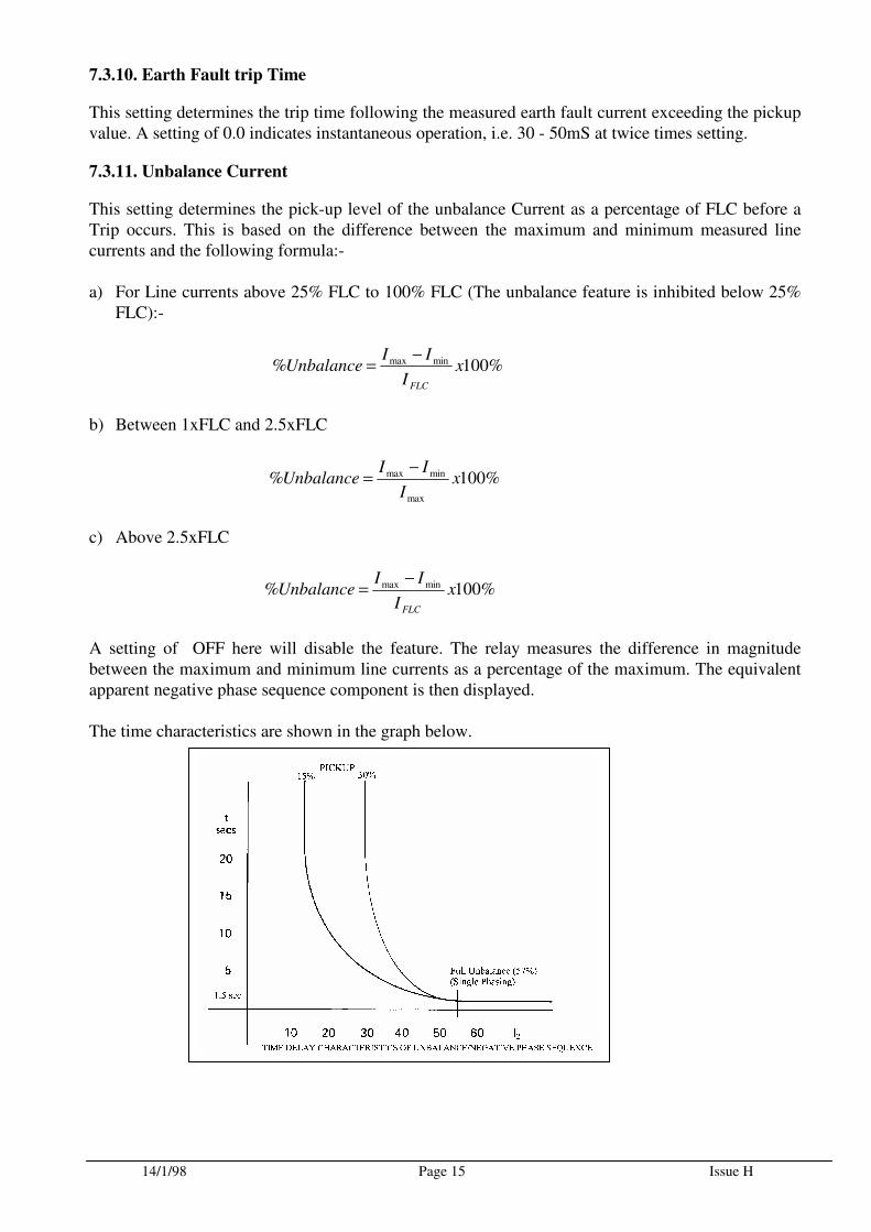
7.3.11. Unbalance Current
This setting determines the pick-up level of the unbalance Current as a percentage of FLC before a Trip occurs. This is based on the difference between the maximum and minimum measured line currents and the following formula:- a) For Line currents above 25% FLC to 100% FLC (The unbalance feature is inhibited below 25%
FLC):-
b) Between 1xFLC and 2.5xFLC
c) Above 2.5xFLC
A setting of OFF here will disable the feature. The relay measures the difference in magnitude between the maximum and minimum line currents as a percentage of the maximum. The equivalent apparent negative phase sequence component is then displayed. The time characteristics are shown in the graph below.
%100% minmax xI
IIUnbalance
FLC
−=
%100%max
minmax xI
IIUnbalance
−=
%100% minmax xI
IIUnbalance
FLC
−=
14/1/98 Page 16 Issue H
7.3.12. Undercurrent Setting
This setting determines the pickup upon an undercurrent, this is generally used to protect against an unloaded machine, e.g. Drive belt failure. A setting of OFF here will disable the feature.
7.3.13. Undercurrent Time
This sets a time between the unit registering an undercurrent level and the actual tripping of the unit.
7.3.14. High Set Overcurrent
This feature is normally enabled when the motor is being controlled by a circuit breaker allowing a much quicker trip time for high fault currents. A setting of OFF here will disable the feature, it is recommended that this feature is disabled for fused contactors.
7.3.15. High Set Overcurrent Time
This setting determines the trip time following the measured current exceeding the pickup value. Note: The High set overcurrent setting is DOUBLED during starting. This feature allows more sensitive short circuit protection on circuit breaker controlled motors whilst avoiding trips due to the asymmetrical transient portion of the starting current.
7.3.16 Low Set Overcurrent
This feature allows a quicker trip time for fault currents, or overloads of a medium magnitude. A setting of OFF here will disable the feature
7.3.17 Low Set Overcurrent Time
This setting determines the trip time following the measured current exceeding the pickup value. NOTE: The Low set feature is not in service during starting. This feature can therefore be used to provide a quick operating definite time stall protection once the motor is running.
7.3.19 Set Password
This allows the user to password protect the Relay to avoid unauthorised changing of parameters. Any four of the pushbuttons may be selected in any order. After pressing <ENTER> the new password is saved. If you intend to change from the default password, please a make a careful note of the new password. If you forget the new password, consult your local agent or P&B Engineering for help on how to restore the default password.
7.3.20 Serial Link Address, RSnn
This setting in the range of 1 to 32 or “OFF” identifies the MPR 3E5 unit to the communications hardware on the RS485 Data Highway.
14/1/98 Page 17 Issue H
7.4 Matrix Setting
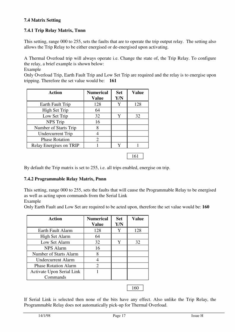
7.4.1 Trip Relay Matrix, Tnnn
This setting, range 000 to 255, sets the faults that are to operate the trip output relay. The setting also allows the Trip Relay to be either energised or de-energised upon activating. A Thermal Overload trip will always operate i.e. Change the state of, the Trip Relay. To configure the relay, a brief example is shown below: Example Only Overload Trip, Earth Fault Trip and Low Set Trip are required and the relay is to energise upon
tripping. Therefore the set value would be: 161
Action Numerical
Value
Set
Y/N
Value
Earth Fault Trip 128 Y 128
High Set Trip 64
Low Set Trip 32 Y 32
NPS Trip 16
Number of Starts Trip 8
Undercurrent Trip 4
Phase Rotation 2
Relay Energises on TRIP 1 Y 1
161
By default the Trip matrix is set to 255, i.e. all trips enabled, energise on trip.
7.4.2 Programmable Relay Matrix, Pnnn
This setting, range 000 to 255, sets the faults that will cause the Programmable Relay to be energised as well as acting upon commands from the Serial Link Example
Only Earth Fault and Low Set are required to be acted upon, therefore the set value would be: 160
Action Numerical
Value
Set
Y/N
Value
Earth Fault Alarm 128 Y 128
High Set Alarm 64
Low Set Alarm 32 Y 32
NPS Alarm 16
Number of Starts Alarm 8
Undercurrent Alarm 4
Phase Rotation Alarm 2
Activate Upon Serial Link Commands
1
160
If Serial Link is selected then none of the bits have any effect. Also unlike the Trip Relay, the Programmable Relay does not automatically pick-up for Thermal Overload.
14/1/98 Page 18 Issue H
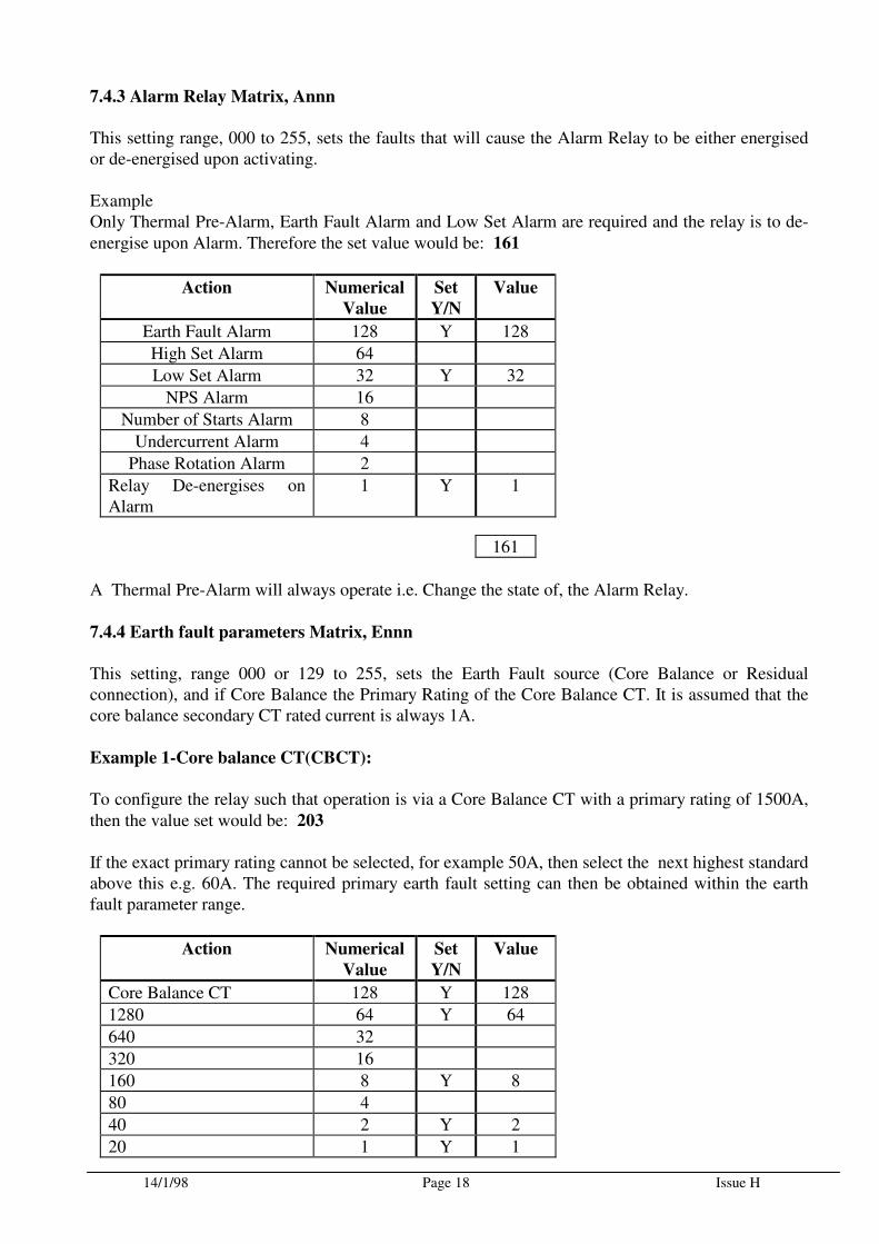
7.4.3 Alarm Relay Matrix, Annn
This setting range, 000 to 255, sets the faults that will cause the Alarm Relay to be either energised or de-energised upon activating. Example Only Thermal Pre-Alarm, Earth Fault Alarm and Low Set Alarm are required and the relay is to de-
energise upon Alarm. Therefore the set value would be: 161
Action Numerical
Value
Set
Y/N
Value
Earth Fault Alarm 128 Y 128
High Set Alarm 64
Low Set Alarm 32 Y 32
NPS Alarm 16
Number of Starts Alarm 8
Undercurrent Alarm 4
Phase Rotation Alarm 2
Relay De-energises on Alarm
1 Y 1
161
A Thermal Pre-Alarm will always operate i.e. Change the state of, the Alarm Relay.
7.4.4 Earth fault parameters Matrix, Ennn
This setting, range 000 or 129 to 255, sets the Earth Fault source (Core Balance or Residual connection), and if Core Balance the Primary Rating of the Core Balance CT. It is assumed that the core balance secondary CT rated current is always 1A.
Example 1-Core balance CT(CBCT):
To configure the relay such that operation is via a Core Balance CT with a primary rating of 1500A,
then the value set would be: 203
If the exact primary rating cannot be selected, for example 50A, then select the next highest standard above this e.g. 60A. The required primary earth fault setting can then be obtained within the earth fault parameter range.
Action Numerical
Value
Set
Y/N
Value
Core Balance CT 128 Y 128
1280 64 Y 64
640 32
320 16
160 8 Y 8
80 4
40 2 Y 2
20 1 Y 1
14/1/98 Page 19 Issue H
203
DIP switch No1 on the 8 way internal switch-group selects the CT Secondary current of the Earth Fault input for a core balance application only i.e. when the matrix Ennn is set at E129 and above. See Section 4.13. For example, if the core balance CT Secondary is 1A and is used with a 5A Earth Fault rated relay, then the DIP Switch No 1 would be left at its normal setting of "OFF".
Example 2-Residual Connection:
To configure the relay for 3 line CT’s, residually connected for the earth fault input, the core balance CT option is NOT selected i.e. numerical value 128 set to “N” i.e. value zero and a primary rating cannot be entered i.e. numbers between 1 and 128 are not possible. The position of DIP Switch No 1 is not relevant in this case.
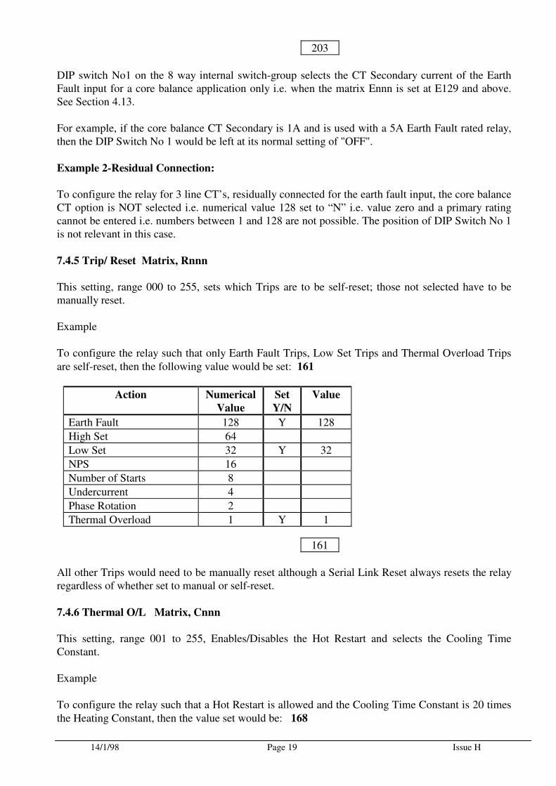
7.4.5 Trip/ Reset Matrix, Rnnn
This setting, range 000 to 255, sets which Trips are to be self-reset; those not selected have to be manually reset. Example To configure the relay such that only Earth Fault Trips, Low Set Trips and Thermal Overload Trips
are self-reset, then the following value would be set: 161
Action Numerical
Value
Set
Y/N
Value
Earth Fault 128 Y 128
High Set 64
Low Set 32 Y 32
NPS 16
Number of Starts 8
Undercurrent 4
Phase Rotation 2
Thermal Overload 1 Y 1
161
All other Trips would need to be manually reset although a Serial Link Reset always resets the relay regardless of whether set to manual or self-reset.
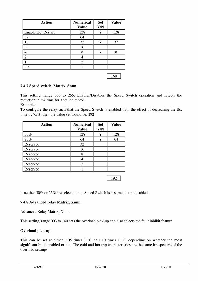
7.4.6 Thermal O/L Matrix, Cnnn
This setting, range 001 to 255, Enables/Disables the Hot Restart and selects the Cooling Time Constant. Example To configure the relay such that a Hot Restart is allowed and the Cooling Time Constant is 20 times
the Heating Constant, then the value set would be: 168
14/1/98 Page 20 Issue H
Action Numerical
Value
Set
Y/N
Value
Enable Hot Restart 128 Y 128
32 64
16 32 Y 32
8 16
4 8 Y 8
2 4
1 2
0.5 1
168
7.4.7 Speed switch Matrix, Snnn
This setting, range 000 to 255, Enables/Disables the Speed Switch operation and selects the reduction in t6x time for a stalled motor. Example To configure the relay such that the Speed Switch is enabled with the effect of decreasing the t6x
time by 75%, then the value set would be: 192
Action Numerical
Value
Set
Y/N
Value
50% 128 Y 128
25% 64 Y 64
Reserved 32
Reserved 16
Reserved 8
Reserved 4
Reserved 2
Reserved 1
192
If neither 50% or 25% are selected then Speed Switch is assumed to be disabled.
7.4.8 Advanced relay Matrix, Xnnn
Advanced Relay Matrix, Xnnn This setting, range 003 to 140 sets the overload pick-up and also selects the fault inhibit feature.
Overload pick-up
This can be set at either 1.05 times FLC or 1.10 times FLC, depending on whether the most significant bit is enabled or not. The cold and hot trip characteristics are the same irrespective of the overload settings.
14/1/98 Page 21 Issue H
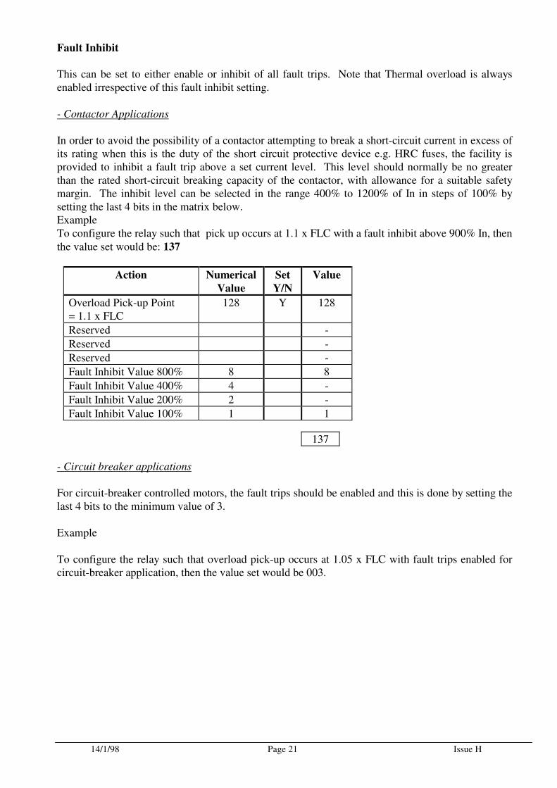
Fault Inhibit
This can be set to either enable or inhibit of all fault trips. Note that Thermal overload is always enabled irrespective of this fault inhibit setting. - Contactor Applications
In order to avoid the possibility of a contactor attempting to break a short-circuit current in excess of its rating when this is the duty of the short circuit protective device e.g. HRC fuses, the facility is provided to inhibit a fault trip above a set current level. This level should normally be no greater than the rated short-circuit breaking capacity of the contactor, with allowance for a suitable safety margin. The inhibit level can be selected in the range 400% to 1200% of In in steps of 100% by setting the last 4 bits in the matrix below. Example To configure the relay such that pick up occurs at 1.1 x FLC with a fault inhibit above 900% In, then
the value set would be: 137
Action Numerical
Value
Set
Y/N
Value
Overload Pick-up Point = 1.1 x FLC
128 Y 128
Reserved -
Reserved -
Reserved -
Fault Inhibit Value 800% 8 8
Fault Inhibit Value 400% 4 -
Fault Inhibit Value 200% 2 -
Fault Inhibit Value 100% 1 1
137
- Circuit breaker applications
For circuit-breaker controlled motors, the fault trips should be enabled and this is done by setting the last 4 bits to the minimum value of 3. Example To configure the relay such that overload pick-up occurs at 1.05 x FLC with fault trips enabled for circuit-breaker application, then the value set would be 003.
14/1/98 Page 22 Issue H
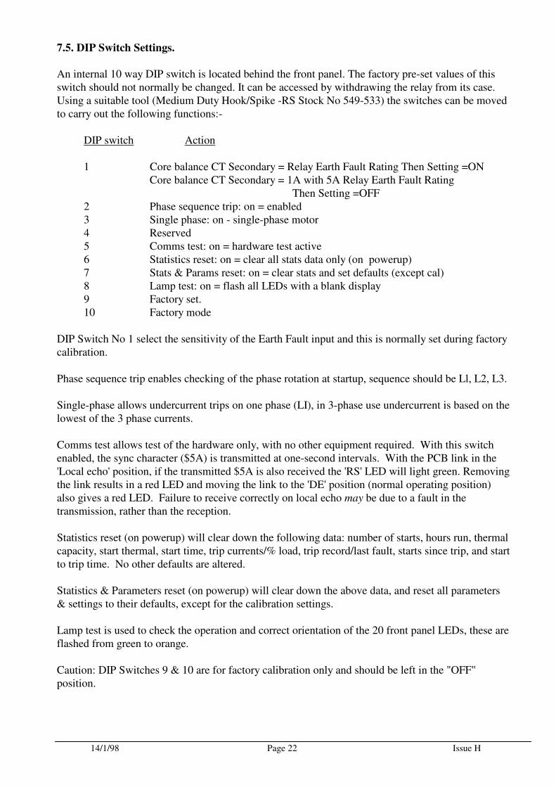
7.5. DIP Switch Settings.
An internal 10 way DIP switch is located behind the front panel. The factory pre-set values of this switch should not normally be changed. It can be accessed by withdrawing the relay from its case. Using a suitable tool (Medium Duty Hook/Spike -RS Stock No 549-533) the switches can be moved to carry out the following functions:-
DIP switch Action
1 Core balance CT Secondary = Relay Earth Fault Rating Then Setting =ON Core balance CT Secondary = 1A with 5A Relay Earth Fault Rating Then Setting =OFF 2 Phase sequence trip: on = enabled 3 Single phase: on - single-phase motor 4 Reserved 5 Comms test: on = hardware test active 6 Statistics reset: on = clear all stats data only (on powerup) 7 Stats & Params reset: on = clear stats and set defaults (except cal) 8 Lamp test: on = flash all LEDs with a blank display 9 Factory set. 10 Factory mode
DIP Switch No 1 select the sensitivity of the Earth Fault input and this is normally set during factory calibration. Phase sequence trip enables checking of the phase rotation at startup, sequence should be Ll, L2, L3. Single-phase allows undercurrent trips on one phase (LI), in 3-phase use undercurrent is based on the lowest of the 3 phase currents. Comms test allows test of the hardware only, with no other equipment required. With this switch enabled, the sync character ($5A) is transmitted at one-second intervals. With the PCB link in the 'Local echo' position, if the transmitted $5A is also received the 'RS' LED will light green. Removing the link results in a red LED and moving the link to the 'DE' position (normal operating position) also gives a red LED. Failure to receive correctly on local echo may be due to a fault in the transmission, rather than the reception. Statistics reset (on powerup) will clear down the following data: number of starts, hours run, thermal capacity, start thermal, start time, trip currents/% load, trip record/last fault, starts since trip, and start to trip time. No other defaults are altered. Statistics & Parameters reset (on powerup) will clear down the above data, and reset all parameters & settings to their defaults, except for the calibration settings. Lamp test is used to check the operation and correct orientation of the 20 front panel LEDs, these are flashed from green to orange.
Caution: DIP Switches 9 & 10 are for factory calibration only and should be left in the "OFF" position.
14/1/98 Page 23 Issue H
7.6. Test Trip
The whole tripping circuit of the protection system may be tested by simulating a fault with the
<TRIP> push button. This button is also used to interrogate the relay for its software version number. In order to enter the test trip mode the user must be in display mode 2 (6.2.2). Upon
pressing the <TRIP> button the display responds with <PSW?>. The password must then be entered, upon entering the correct password the display indicates the software version number, and the output relays are operated in a cyclic manner illuminating the S/R, A, & KA LEDS in sympathy.
In order to reset the relay, a single press of the <SELECT/RESET> push button will return to mode 2, alternatively after approximately 2 minutes the relay will automatically return to the normal mode ( blank display ) if no activity is noted on the front push buttons.
7.7. Reset
There are two ways in which to reset the MPR 3E5 relay:
7.7.1 Hand reset
By pressing the <SELECT/RESET> for approximately 3 seconds the relay is reset.
7.7.2 Auto-reset at Power Up
After loss of supply voltage and upon its reconnection the unit resets itself and displays P&B. This resetting of the unit does not effect the set parameters which are stored in an EEPROM.
7.8. Phase Rotation
This feature detects incorrect phase sequence and is only active during a start. This can be used to detect incorrect phase connections to the motor during commissioning. Ten sequence errors in a row must be detected in order to trip the relay. The DIP Switch No 2 on the internal 10 way switch-group must be set to "ON" to enable this feature.
7.9. Setting value calculation
In order to ensure that protection relays form an integral part of any system, a full protection co-ordination study should normally be undertaken which considers both upstream and downstream equipment. Further details may be obtained by contacting P&B Engineering.
14/1/98 Page 24 Issue H
8. Relay case
The MPR 3E5 is delivered in an individual case for flush mounting.
8.1 Individual case
The MPR 3E5 is supplied in a UK manufactured industry standard drawout case suitable for flush mounting. For case dimension and cut-out, refer to Technical Data.
8.2 Rack mounting
MPR 3E5 relays may be supplied mounted in 19" racks if specified by the user.
8.3 Terminal connections
The MPR 3E5 plug in module is supplied in a case which has a very compact plug and socket
connector. The current terminals are equipped with self closing short circuit contacts. Thus the MPR
3E5 module can be unplugged even with current flowing without endangering personnel.
9. Commissioning And Testing The MPR3E5.
9.1. Commissioning.
Auxiliary Power Supply The relay requires an auxiliary power supply connected to terminals 1 & 2
Two auxiliary power supply versions are available:
Vaux = 24V in a range from 16V to 60V AC 50/60Hz or in a range from 16V to 80V DC Vaux = 110V in a range from 50V to 265V AC 50/60Hz or in a range from 70V to 265V DC
When the stall input is used, the above auxiliary supply or an alternative supply, within the same range should be connected to terminals 19, & 20 via a speed switch.
Requirements for the main Current Transformers
In order to ensure the correct operation of the MPR 3E5 range of relays, Protection class CT's to BS3938/BS7626(IEC185) must be utilised. Measuring CT's are generally NOT a suitable alternative.
CT's should be chosen such that saturation, or loss of accuracy does not occur within the settings and operation ranges of the relays. In the absence of known settings the following may be regarded as an approximate guide.
For the Line CT’s
For 1A secondary
CT class 5P10 or 10P10 2.5VA (Allowing for up to 1.5Ω of secondary lead resistance)
14/1/98 Page 25 Issue H
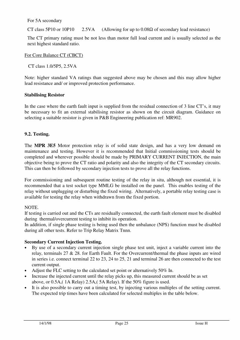
For 5A secondary
CT class 5P10 or 10P10 2.5VA (Allowing for up to 0.08Ω of secondary lead resistance)
The CT primary rating must be not less than motor full load current and is usually selected as the next highest standard ratio.
For Core Balance CT (CBCT)
CT class 1.0/5P5, 2.5VA
Note: higher standard VA ratings than suggested above may be chosen and this may allow higher lead resistance and/ or improved protection performance.
Stabilising Resistor
In the case where the earth fault input is supplied from the residual connection of 3 line CT’s, it may be necessary to fit an external stabilising resistor as shown on the circuit diagram. Guidance on selecting a suitable resistor is given in P&B Engineering publication ref: MR902.
9.2. Testing.
The MPR 3E5 Motor protection relay is of solid state design, and has a very low demand on maintenance and testing. However it is recommended that Initial commissioning tests should be completed and wherever possible should be made by PRIMARY CURRENT INJECTION, the main objective being to prove the CT ratio and polarity and also the integrity of the CT secondary circuits. This can then be followed by secondary injection tests to prove all the relay functions. For commissioning and subsequent routine testing of the relay in situ, although not essential, it is recommended that a test socket type MMLG be installed on the panel. This enables testing of the relay without unplugging or disturbing the fixed wiring. Alternatively, a portable relay testing case is available for testing the relay when withdrawn from the fixed portion.
NOTE. If testing is carried out and the CTs are residually connected, the earth fault element must be disabled during thermal/overcurrent testing to inhibit its operation. In addition, if single phase testing is being used then the unbalance (NPS) function must be disabled during all other tests. Refer to Trip Relay Matrix Tnnn.
Secondary Current Injection Testing.
• By use of a secondary current injection single phase test unit, inject a variable current into the relay, terminals 27 & 28. for Earth Fault. For the Overcurrent/thermal the phase inputs are wired in series i.e. connect terminal 22 to 23, 24 to 25, 21 and terminal 26 are then connected to the test current output.
• Adjust the FLC setting to the calculated set point or alternatively 50% In. • Increase the injected current until the relay picks up, this measured current should be as set
above, or 0.5A,( 1A Relay) 2.5A,( 5A Relay). If the 50% figure is used. • It is also possible to carry out a timing test, by injecting various multiples of the setting current.
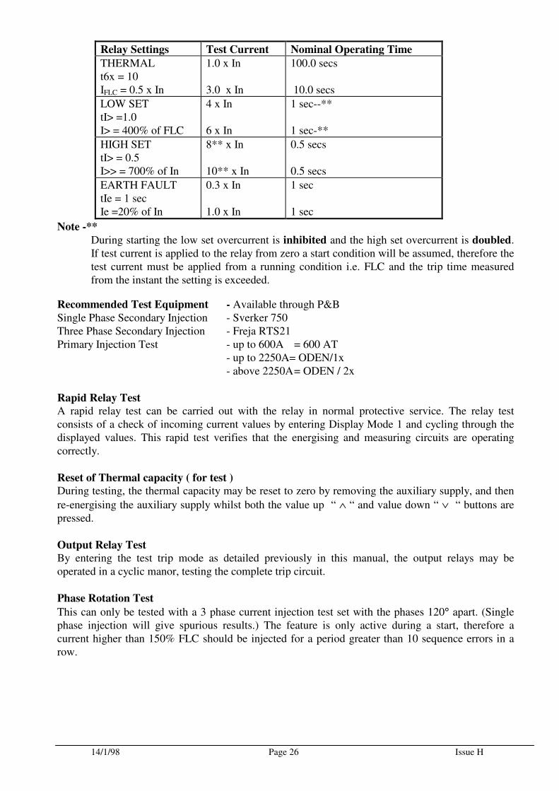
The expected trip times have been calculated for selected multiples in the table below.
14/1/98 Page 26 Issue H
Relay Settings Test Current Nominal Operating Time
THERMAL t6x = 10 IFLC = 0.5 x In
1.0 x In 3.0 x In
100.0 secs 10.0 secs
LOW SET tI> =1.0 I> = 400% of FLC
4 x In 6 x In
1 sec--** 1 sec-**
HIGH SET tI> = 0.5 I>> = 700% of In
8** x In 10** x In
0.5 secs 0.5 secs
EARTH FAULT tIe = 1 sec Ie =20% of In
0.3 x In 1.0 x In
1 sec 1 sec
Note -**
During starting the low set overcurrent is inhibited and the high set overcurrent is doubled. If test current is applied to the relay from zero a start condition will be assumed, therefore the test current must be applied from a running condition i.e. FLC and the trip time measured from the instant the setting is exceeded.
Recommended Test Equipment - Available through P&B Single Phase Secondary Injection - Sverker 750 Three Phase Secondary Injection - Freja RTS21 Primary Injection Test - up to 600A = 600 AT - up to 2250A= ODEN/1x - above 2250A = ODEN / 2x
Rapid Relay Test
A rapid relay test can be carried out with the relay in normal protective service. The relay test consists of a check of incoming current values by entering Display Mode 1 and cycling through the displayed values. This rapid test verifies that the energising and measuring circuits are operating correctly.
Reset of Thermal capacity ( for test )
During testing, the thermal capacity may be reset to zero by removing the auxiliary supply, and then
re-energising the auxiliary supply whilst both the value up “ ∧ “ and value down “ ∨ “ buttons are pressed.
Output Relay Test
By entering the test trip mode as detailed previously in this manual, the output relays may be operated in a cyclic manor, testing the complete trip circuit.
Phase Rotation Test
This can only be tested with a 3 phase current injection test set with the phases 120° apart. (Single phase injection will give spurious results.) The feature is only active during a start, therefore a current higher than 150% FLC should be injected for a period greater than 10 sequence errors in a row.
14/1/98 Page 27 Issue H
Guide to settings
In order to ensure full protection to the equipment, a co-ordination study must be made that takes account of all possible faults or conditions that may occur, this usually takes the form of ensuring that all of the tripping characteristic of the MPR3E5, is between all the possible starting characteristics, and the full thermal withstand of the machine, for both hot & cold conditions. In the absence of the above information, it is usual to set the overload pick-up at 105%, Is at the FLC of the machine, low set ( I> ) OFF, hot/cold ratio at 50% with the high set ( I>> ) set OFF for fuse contactors, and at 8x FLC, tI>> at 0.0, for circuit breakers. In order to determine a suitable value for t6x, the start time of the machine must be obtained. A setting for t6x may then be selected as follows,
For Direct On Line starters, t6x ≅ 1.1 x start time.
For Star-Delta starters, t6x ≅ 0.35 x start time These are a guide only, and are unlikely to enable a hot start of the machine.
Co-ordination With Short Circuit Protective Device.
It is important that the relay parameter settings, trip relay matrix settings and characteristics should be carefully co-ordinated with that of the Short Circuit Protective Device for all fault conditions. This is especially important in the case of a fused contactor starter where it is necessary to ensure that the contactor can never attempt to break a fault current in excess of its rating. For this purpose a setting parameter is provided to inhibit all fault protection trips above a range 4 to 12 x In current. NOTE THAT THE THERMAL OVERLOAD PROTECTION FUNCTION IS ALWAYS ENABLED IRRESPECTIVE OF THE INHIBIT SETTING.
14/1/98 Page 28 Issue H
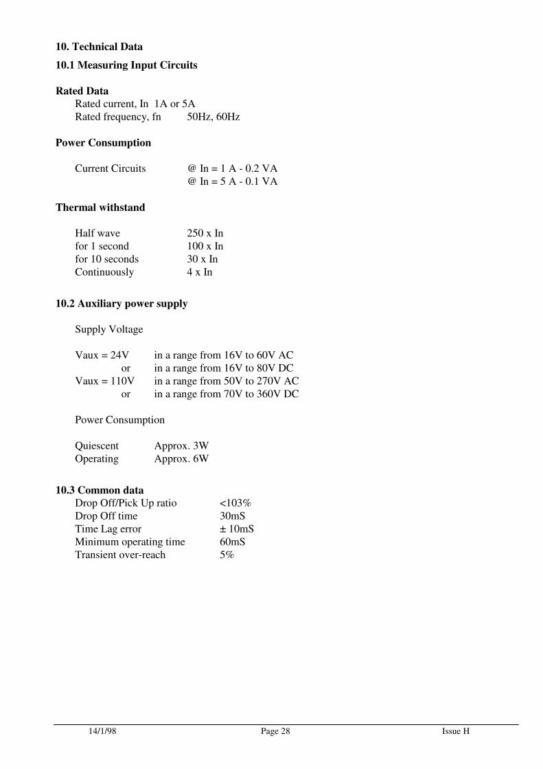
10. Technical Data
10.1 Measuring Input Circuits
Rated Data
Rated current, In 1A or 5A Rated frequency, fn 50Hz, 60Hz
Power Consumption Current Circuits @ In = 1 A - 0.2 VA @ In = 5 A - 0.1 VA
Thermal withstand
Half wave 250 x In for 1 second 100 x In for 10 seconds 30 x In Continuously 4 x In
10.2 Auxiliary power supply
Supply Voltage Vaux = 24V in a range from 16V to 60V AC or in a range from 16V to 80V DC Vaux = 110V in a range from 50V to 270V AC or in a range from 70V to 360V DC Power Consumption Quiescent Approx. 3W Operating Approx. 6W
10.3 Common data
Drop Off/Pick Up ratio <103% Drop Off time 30mS Time Lag error ± 10mS Minimum operating time 60mS Transient over-reach 5%
14/1/98 Page 29 Issue H
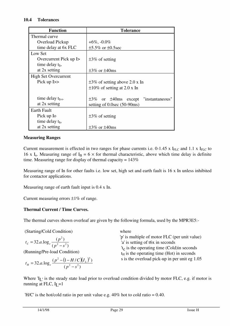
10.4 Tolerances
Function Tolerance
Thermal curve Overload Pickup time delay at 6x FLC
+6%, -0.0%
±5.5% or ±0.5sec
Low Set Overcurrent Pick up I> time delay tI> at 2x setting
±3% of setting
±3% or ±40ms
High Set Overcurrent Pick up I>> time delay tI>> at 2x setting
±3% of setting above 2.0 x In
±10% of setting at 2.0 x In
±3% or ±40ms except "instantaneous" setting of 0.0sec (50-90ms)
Earth Fault Pick up Io time delay tIo at 2x setting
±3% of setting
±3% or ±40ms
Measuring Ranges
Current measurement is effected in two ranges for phase currents i.e. 0-1.45 x IFLC and 1.1 x IFLC to
16 x In. Measuring range of In = 6 × for thermal characteristic, above which time delay is definite time. Measuring range for display of thermal capacity = 143% Measuring range of In for other faults i.e. low set, high set and earth fault is 16 x In unless inhibited for contactor applications. Measuring range of earth fault input is 0.4 x In.
Current measuring errors ±1% of range.
Thermal Current / Time Curves.
The thermal curves shown overleaf are given by the following formula, used by the MPR3E5:- (Starting/Cold Condition)
(Running/Pre-load Condition)
where 'p' is multiple of motor FLC (per unit value) 'a' is setting of t6x in seconds 'tc is the operating time (Cold)in seconds tH is the operating time (Hot) in seconds s is the overload pick-up in per unit eg 1.05
Where 'IL' is the steady state load prior to overload condition divided by motor FLC, e.g. if motor is running at FLC, IL=1 'H/C' is the hot/cold ratio in per unit value e.g. 40% hot to cold ratio = 0.40.
)(
)(log..32
22
2
sp
pat eC
−=
( )( ))(
)/1(log..32
22
22
sp
ICHpat L
eH−
−−=
17/12/97 Page 30 Issue H
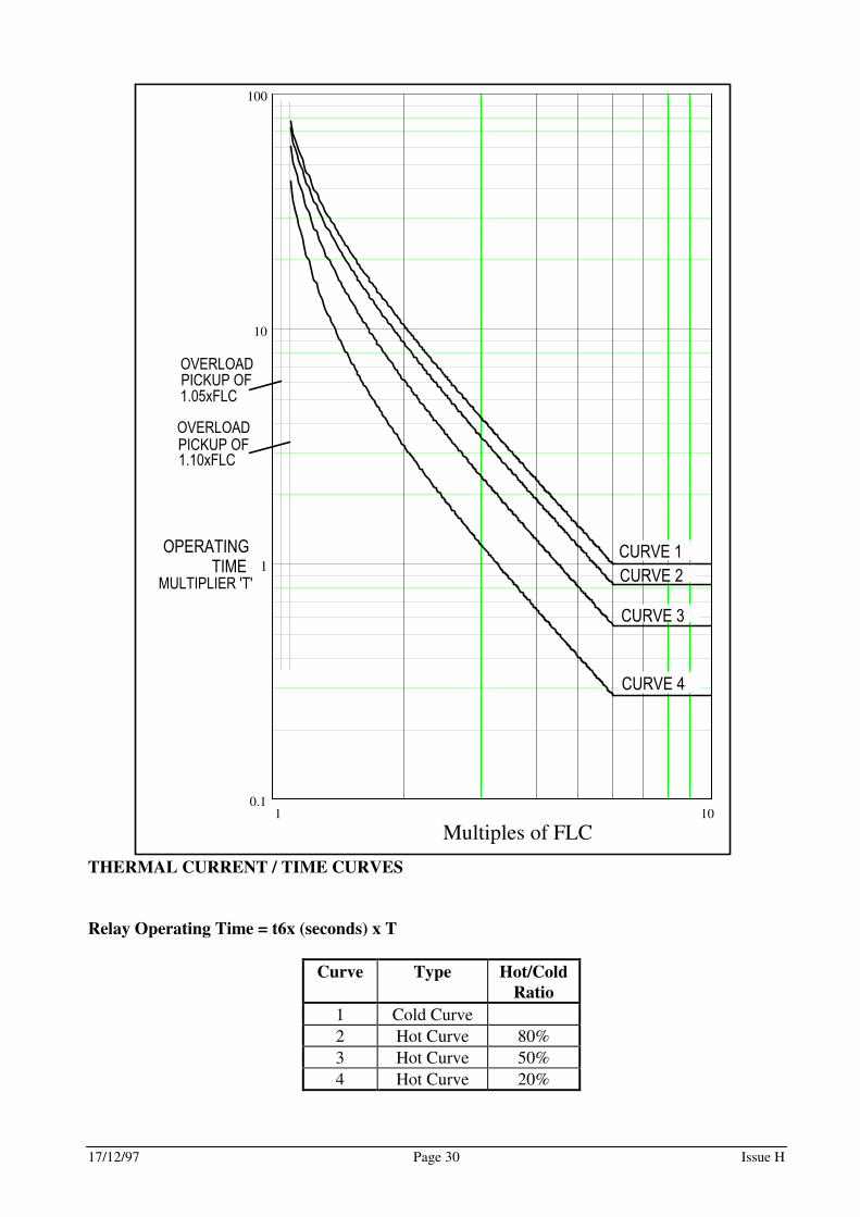
THERMAL CURRENT / TIME CURVES
Relay Operating Time = t6x (seconds) x T
Curve Type Hot/Cold
Ratio
1 Cold Curve
2 Hot Curve 80%
3 Hot Curve 50%
4 Hot Curve 20%
1 100.1
1
10
100
Multiples of FLC
CURVE 2
CURVE 3
CURVE 4
CURVE 1
OVERLOAD
PICKUP OF
1.05xFLC
OVERLOAD
PICKUP OF
1.10xFLC
OPERATING
TIMEMULTIPLIER 'T'
17/12/97 Page 31 Issue H
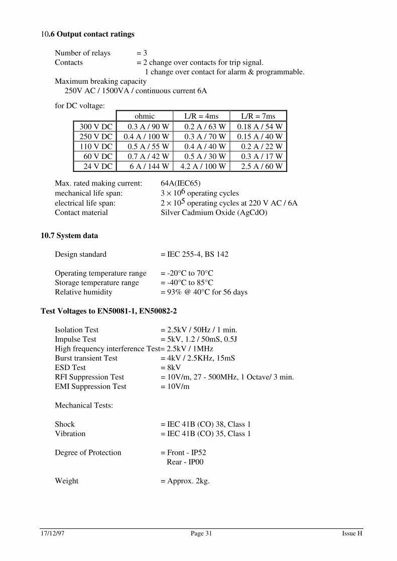
10.6 Output contact ratings
Number of relays = 3 Contacts = 2 change over contacts for trip signal. 1 change over contact for alarm & programmable. Maximum breaking capacity 250V AC / 1500VA / continuous current 6A
for DC voltage:
ohmic L/R = 4ms L/R = 7ms
300 V DC 0.3 A / 90 W 0.2 A / 63 W 0.18 A / 54 W
250 V DC 0.4 A / 100 W 0.3 A / 70 W 0.15 A / 40 W
110 V DC 0.5 A / 55 W 0.4 A / 40 W 0.2 A / 22 W
60 V DC 0.7 A / 42 W 0.5 A / 30 W 0.3 A / 17 W
24 V DC 6 A / 144 W 4.2 A / 100 W 2.5 A / 60 W
Max. rated making current: 64A(IEC65)
mechanical life span: 3 × 10⁶ operating cycles
electrical life span: 2 × 10⁵ operating cycles at 220 V AC / 6A Contact material Silver Cadmium Oxide (AgCdO)
10.7 System data
Design standard = IEC 255-4, BS 142 Operating temperature range = -20°C to 70°C Storage temperature range = -40°C to 85°C Relative humidity = 93% @ 40°C for 56 days
Test Voltages to EN50081-1, EN50082-2
Isolation Test = 2.5kV / 50Hz / 1 min. Impulse Test = 5kV, 1.2 / 50mS, 0.5J High frequency interference Test= 2.5kV / 1MHz Burst transient Test = 4kV / 2.5KHz, 15mS ESD Test = 8kV RFI Suppression Test = 10V/m, 27 - 500MHz, 1 Octave/ 3 min. EMI Suppression Test = 10V/m Mechanical Tests: Shock = IEC 41B (CO) 38, Class 1 Vibration = IEC 41B (CO) 35, Class 1 Degree of Protection = Front - IP52 Rear - IP00 Weight = Approx. 2kg.
17/12/97 Page 32 Issue H
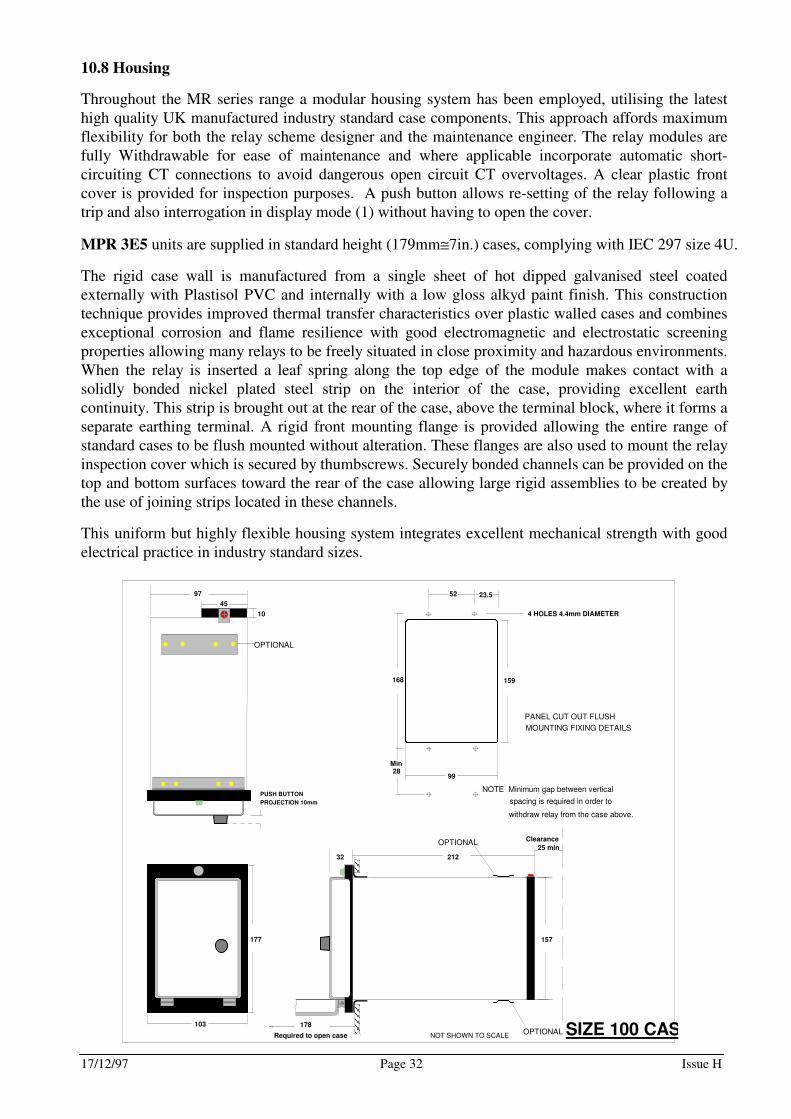
10.8 Housing
Throughout the MR series range a modular housing system has been employed, utilising the latest high quality UK manufactured industry standard case components. This approach affords maximum flexibility for both the relay scheme designer and the maintenance engineer. The relay modules are fully Withdrawable for ease of maintenance and where applicable incorporate automatic short-circuiting CT connections to avoid dangerous open circuit CT overvoltages. A clear plastic front cover is provided for inspection purposes. A push button allows re-setting of the relay following a trip and also interrogation in display mode (1) without having to open the cover.
MPR 3E5 units are supplied in standard height (179mm≅7in.) cases, complying with IEC 297 size 4U.
The rigid case wall is manufactured from a single sheet of hot dipped galvanised steel coated externally with Plastisol PVC and internally with a low gloss alkyd paint finish. This construction technique provides improved thermal transfer characteristics over plastic walled cases and combines exceptional corrosion and flame resilience with good electromagnetic and electrostatic screening properties allowing many relays to be freely situated in close proximity and hazardous environments. When the relay is inserted a leaf spring along the top edge of the module makes contact with a solidly bonded nickel plated steel strip on the interior of the case, providing excellent earth continuity. This strip is brought out at the rear of the case, above the terminal block, where it forms a separate earthing terminal. A rigid front mounting flange is provided allowing the entire range of standard cases to be flush mounted without alteration. These flanges are also used to mount the relay inspection cover which is secured by thumbscrews. Securely bonded channels can be provided on the top and bottom surfaces toward the rear of the case allowing large rigid assemblies to be created by the use of joining strips located in these channels.
This uniform but highly flexible housing system integrates excellent mechanical strength with good electrical practice in industry standard sizes.
PANEL CUT OUT FLUSH
MOUNTING FIXING DETAILS
4 HOLES 4.4mm DIAMETER
99
168 159
52 23.5
10
97
45
PUSH BUTTON
PROJECTION 10mm
NOT SHOWN TO SCALE
103
177
212
Clearance
25 min
157
32
OPTIONAL
OPTIONAL
OPTIONAL
Min28
NOTE Minimum gap between vertical
spacing is required in order to
withdraw relay from the case above.
178
Required to open case SIZE 100 CASE
17/12/97 Page 33 Issue H
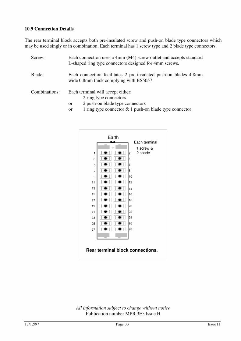
10.9 Connection Details
The rear terminal block accepts both pre-insulated screw and push-on blade type connectors which may be used singly or in combination. Each terminal has 1 screw type and 2 blade type connectors.
Screw: Each connection uses a 4mm (M4) screw outlet and accepts standard L-shaped ring type connectors designed for 4mm screws.
Blade: Each connection facilitates 2 pre-insulated push-on blades 4.8mm
wide 0.8mm thick complying with BS5057.
Combinations: Each terminal will accept either; 2 ring type connectors or 2 push-on blade type connectors or 1 ring type connector & 1 push-on blade type connector
1
3
5
7
9
11
13
15
17
19
21
23
25
27
2
4
6
8
10
12
14
16
18
20
22
24
26
28
Earth
Rear terminal block connections.
Each terminal
1 screw &2 spade
All information subject to change without notice
Publication number MPR 3E5 Issue H
17/12/97 Page 34 Issue H
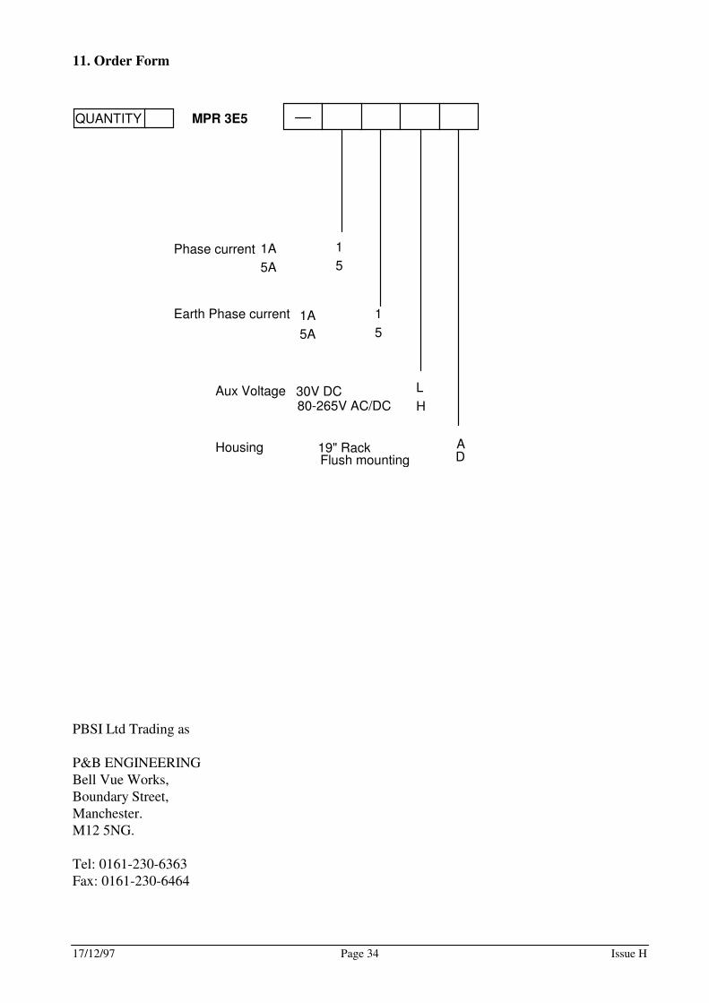
11. Order Form
MPR 3E5
AD
Housing 19" RackFlush mounting
QUANTITY
Aux Voltage 30V DC 80-265V AC/DC
L
H
Phase current 1
5
1A
5A
Earth Phase current 1
5
1A
5A
PBSI Ltd Trading as P&B ENGINEERING Bell Vue Works, Boundary Street, Manchester. M12 5NG. Tel: 0161-230-6363 Fax: 0161-230-6464