Embed Size (px)
Citation preview
1
MJC-8 Q400
PILOT EDITION
Version 1.0
Control Panel Guide
Copyright © Majestic Software 2012,2013

2
Contents
1. Introduction .................................................................................................. 3
2. EFIS page .................................................................................................... 4
3. SYSTEM page ............................................................................................. 5
4. Flight Controls page ..................................................................................... 7
5. Engine Controls page .................................................................................. 9
6. Weight and Balance page .......................................................................... 10
3
1. Introduction
The Control Panel application (or CPAN) is used to configure the numerous
aspects of the Majestic Software MJC8Q400 addon. To make the full use of the
capabilities provided by CPAN, it is important to understand how exactly the
configuration is performed within each of the aspects.
In general, most of the information the CPAN works with, is saved within the
mjc84.ini file (found in the /ini folder of the MJC8Q400 aircraft installation).
The Control Panel application can be accessed from the Windows Start menu,
under the “Majestic Software”, “MJC8Q400” section.
Upon the start, CPAN will load the mjc84.ini parameters. The changes made by
the user on any page (except for Weight&Balance page), will be saved back
into the mjc84.ini file.
It is important not to modify the mjc84.ini file manually while the cpan is running,
as your manual changes will most likely to be over-written, at latest when
closing the application.
The Weight and Balance page however does not reference the mjc84.ini file
parameters. Instead the configuration resulted from the W&B calculation is sent
directly to the MJC8Q400 addon via the Microsoft FSX Simconnect interface.
4
2. EFIS page
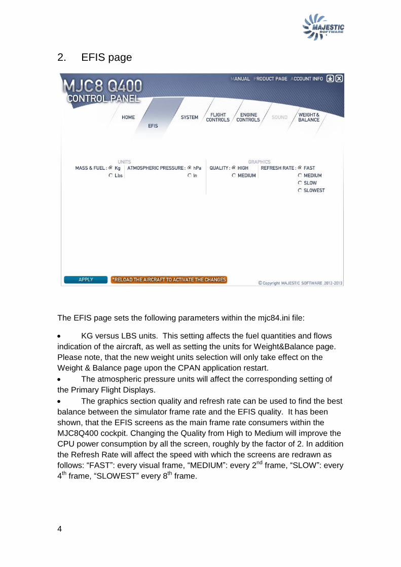
The EFIS page sets the following parameters within the mjc84.ini file:
KG versus LBS units. This setting affects the fuel quantities and flows
indication of the aircraft, as well as setting the units for Weight&Balance page.
Please note, that the new weight units selection will only take effect on the
Weight & Balance page upon the CPAN application restart.
The atmospheric pressure units will affect the corresponding setting of
the Primary Flight Displays.
The graphics section quality and refresh rate can be used to find the best
balance between the simulator frame rate and the EFIS quality. It has been
shown, that the EFIS screens as the main frame rate consumers within the
MJC8Q400 cockpit. Changing the Quality from High to Medium will improve the
CPU power consumption by all the screen, roughly by the factor of 2. In addition
the Refresh Rate will affect the speed with which the screens are redrawn as
follows: “FAST”: every visual frame, “MEDIUM”: every 2nd frame, “SLOW”: every
4th frame, “SLOWEST” every 8th frame.
5
3. SYSTEM page
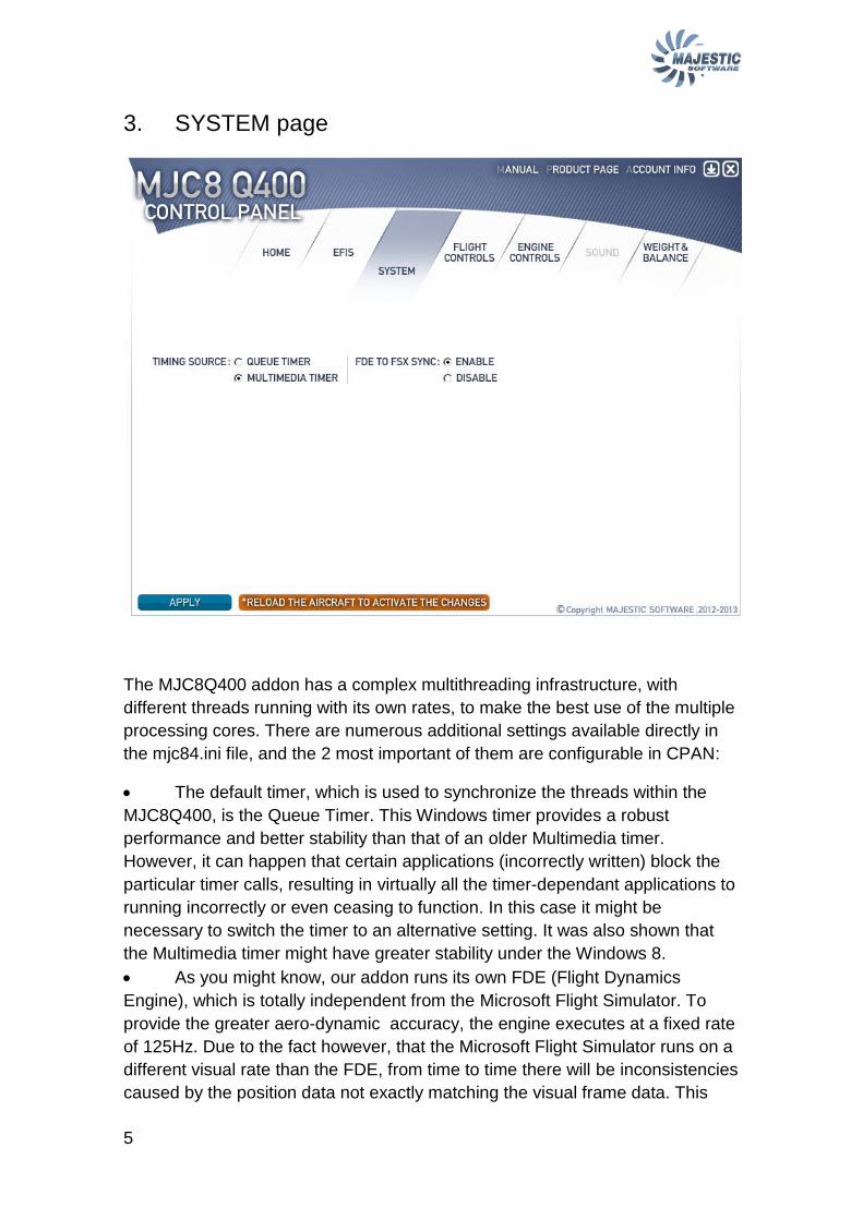
The MJC8Q400 addon has a complex multithreading infrastructure, with
different threads running with its own rates, to make the best use of the multiple
processing cores. There are numerous additional settings available directly in
the mjc84.ini file, and the 2 most important of them are configurable in CPAN:
The default timer, which is used to synchronize the threads within the
MJC8Q400, is the Queue Timer. This Windows timer provides a robust
performance and better stability than that of an older Multimedia timer.
However, it can happen that certain applications (incorrectly written) block the
particular timer calls, resulting in virtually all the timer-dependant applications to
running incorrectly or even ceasing to function. In this case it might be
necessary to switch the timer to an alternative setting. It was also shown that
the Multimedia timer might have greater stability under the Windows 8.
As you might know, our addon runs its own FDE (Flight Dynamics
Engine), which is totally independent from the Microsoft Flight Simulator. To
provide the greater aero-dynamic accuracy, the engine executes at a fixed rate
of 125Hz. Due to the fact however, that the Microsoft Flight Simulator runs on a
different visual rate than the FDE, from time to time there will be inconsistencies
caused by the position data not exactly matching the visual frame data. This

6
inconsistency can be reduced by setting the FDE to FSX sync option, in which
case the FDE will pay attention to the visual frames of the flight simulator and
apply slight timing corrections in order to precisely match the timing of the Flight
Simulator. Please note however, that this option must be disabled when the
unlimited FPS option of the Flight Simulator is selected, which is due to the
higher frame rate oscillations.
7
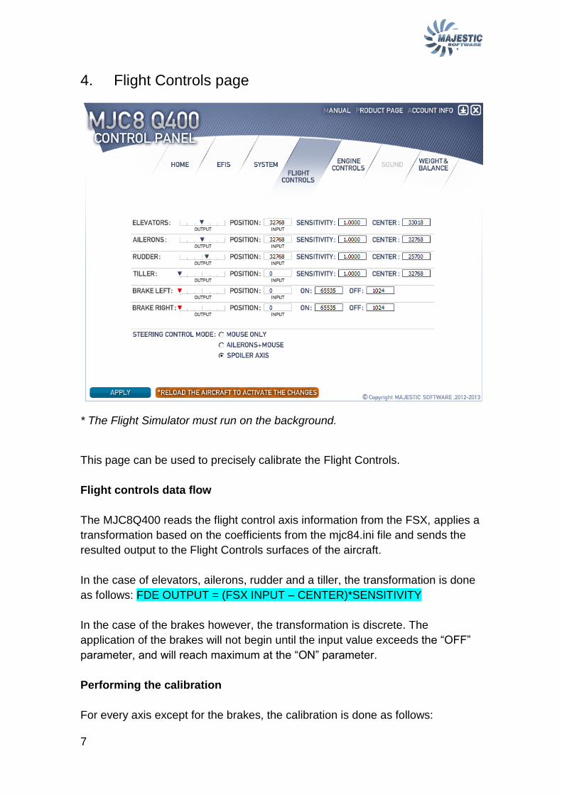
4. Flight Controls page
* The Flight Simulator must run on the background.
This page can be used to precisely calibrate the Flight Controls.
Flight controls data flow
The MJC8Q400 reads the flight control axis information from the FSX, applies a
transformation based on the coefficients from the mjc84.ini file and sends the
resulted output to the Flight Controls surfaces of the aircraft.
In the case of elevators, ailerons, rudder and a tiller, the transformation is done
as follows: FDE OUTPUT = (FSX INPUT – CENTER)*SENSITIVITY
In the case of the brakes however, the transformation is discrete. The
application of the brakes will not begin until the input value exceeds the “OFF”
parameter, and will reach maximum at the “ON” parameter.
Performing the calibration
For every axis except for the brakes, the calibration is done as follows:
8
1. Center the controls. Enter the indicated “INPUT” value into the
“CENTER” field
2. Apply the full left and right deflections, find the “SENSITIVITY” parameter
which would result in the full scale “OUTPUT” marker movement.
* It is highly recommended to ensure the full deflection of all the flight controls.
Our Flight Dynamics Engine was carefully tuned to reproduce the behavior of
the real plane, under condition that the full deflection is available.
To tune up the brakes:
1. Make several brakes application, release the brakes
2. Push the brake slightly to the setting which you would like to have for the
minimal brake application. Note and copy the “INPUT” value into the “OFF” field
3. Push the brake completely in, note the “INPUT” value, reduce the value
slightly (say, by factor of 512), to make sure the maximum application is
reached shortly prior to the complete brake axis deflection. Enter the desired
value into the ON field. Verify the desired braking output, shown by the
“OUTPUT” scale.
Changing the Steering Control Mode
Due to the fact that the Dash-8 steering requires a steering tiller to operate on
the ground, we provide several ways to control the tiller:
“Mouse only”: It is always possible to drag the tiller handle (in
the virtual cockpit) with the mouse.
“Ailerons+Mouse”: Tiller will be linked to the aileron axis below 40kts
Indicated Airspeed. When selecting this option, do not forget to defer the
application of the ailerons on takeoff and landings (especially for crosswind
compensation)
“Spoiler axis”: The FSX spoiler axis are operating the tiller.
Use this function when the dedicated hardware steering axis are available.
9
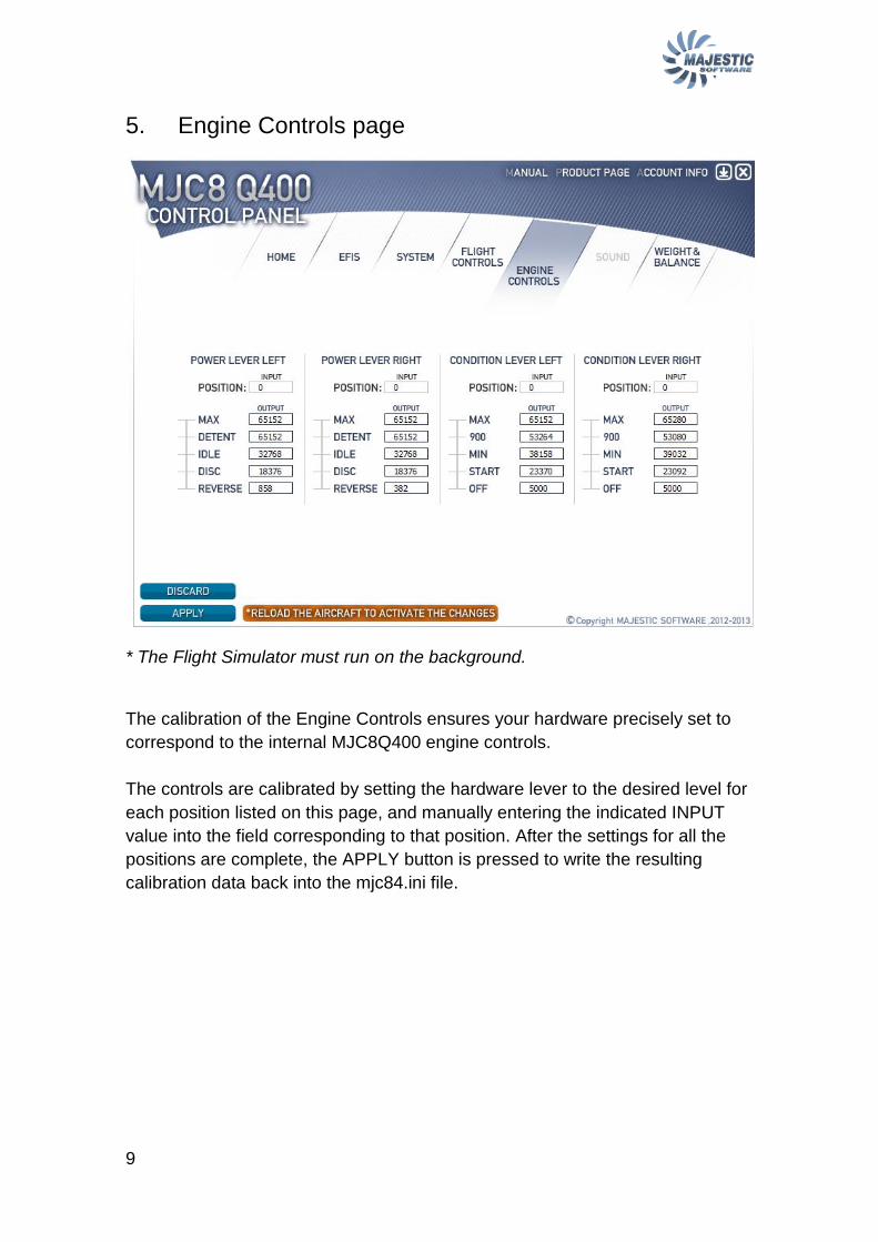
5. Engine Controls page
* The Flight Simulator must run on the background.
The calibration of the Engine Controls ensures your hardware precisely set to
correspond to the internal MJC8Q400 engine controls.
The controls are calibrated by setting the hardware lever to the desired level for
each position listed on this page, and manually entering the indicated INPUT
value into the field corresponding to that position. After the settings for all the
positions are complete, the APPLY button is pressed to write the resulting
calibration data back into the mjc84.ini file.
10
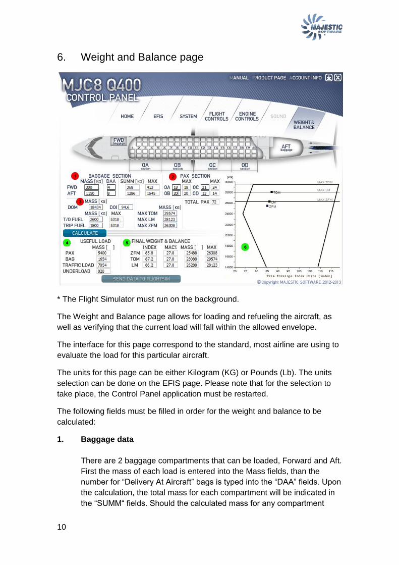
6. Weight and Balance page
* The Flight Simulator must run on the background.
The Weight and Balance page allows for loading and refueling the aircraft, as
well as verifying that the current load will fall within the allowed envelope.
The interface for this page correspond to the standard, most airline are using to
evaluate the load for this particular aircraft.
The units for this page can be either Kilogram (KG) or Pounds (Lb). The units
selection can be done on the EFIS page. Please note that for the selection to
take place, the Control Panel application must be restarted.
The following fields must be filled in order for the weight and balance to be
calculated:
1. Baggage data
There are 2 baggage compartments that can be loaded, Forward and Aft.
First the mass of each load is entered into the Mass fields, than the
number for “Delivery At Aircraft” bags is typed into the “DAA” fields. Upon
the calculation, the total mass for each compartment will be indicated in
the “SUMM“ fields. Should the calculated mass for any compartment
11
exceed the maximum load shown in the “MAX” field, that mass will be
indicated in red color.
2. Passenger data
Passenger data is entered for each of 4 sections (please see the picture
of the aircraft plan at the top of the page). The MAX field indicates the
maximum number of passengers that can be seated in a particular
section.
3. Basic Mass and index, Fuel Mass
The DOM, or Dry Operating Mass is than entered into the dialog. The
DOM is the most common weight concept used by the airlines, as
opposite to the Empty Weight, more often utilized by the General
Aviation. The DOM can be defined as the mass of the aircraft, crew,
catering and fluids (water, oil, braking fluids..), everything except for the
passengers, baggage and fuel. We have prefilled this value with
18434Kg, which is a usual DOM for a middle range flight. The next field,
called “DOI”, means Dry Operating Index and reflects a deviation in the
configuration, depending upon the type of flight performed. It can reflect
the reduced or increased number of flight crew, or different catering
options. In this product we assume a typical “DOI” of 94.6.
After the Operating Data, the Fuel Mass for the fuel that the aircraft will
carry at takeoff, is entered into the “T/O FUEL“ field. The amount of fuel
that is to be burned during the trip is entered into the “TRIP FUEL” field.
When all the data above are entered, the “CALCULATE” button is pressed to
make the W&B calculation. If the results are found acceptable, the “SEND
DATA TO FLIGHT SIM” button is pressed to apply the entered load and the fuel
to the MJC8 Q400 addon. Upon the successful data transfer the Flight
Simulator will be put in a paused state.
* Please note, that the MJC8 Q400 addon must be loaded into the flight
simulator for the data transfer to function.
* Please note, that the applied data will be lost should the user load a different
flight, or apply the “flight reset” function. To prevent loosing the load data, it is
recommended to save the flight as soon as practicable after loading the aircraft
from the Weight & Balance page.
The resulted from calculation data is presented both numerically and graphically
in the following 3 sections:
12
4. Useful load
The useful load data allows the pilot to take an additional last minute load. First,
the current amount of the useful load is shown in the “TRAFFIC LOAD” field,
which equals to the weight of passengers added to the weight of the baggage.
Than most importantly, the “UNDERLOAD” entry shows how much more load
the aircraft can take, before it exceeds ANY of 3 maximum allowed weights
(Zero Fuel Weight, Takeoff and Landing weights). Effectively upon the load
completion the pilot can still take up to the “UNDERLOAD” of additional weight.
5. Final Weight & Balance
The data in this section is shown for each of the 3 cases: Zero Fuel
configuration, Takeoff configuration, Landing configuration.
For each of the configurations, the following parameters are indicated:
Manufacturer specific Trim Index: This index has the same units as the
DOI index, and is used for more convenience as compared to the MAC
percentage. The index is used in both the numerical and the graphical
representations in the sections 5 and 6, and indicates visually how much
reserve the aircraft balance still has trim-wise.
MAC%. This is a location of the Center of Gravity within the Mean Aero
dynamical Cord length, in Percent.
MASS is the calculated mass for the current configuration
MAX is a maximum allowed mass for the current configuration
Should any parameter exceed the allowed envelope, the color for that
parameter will change to Red.
6. Weight and Balance envelope
This envelope graphically presents the Load and Balance limits for the aircraft,
with the mass units shown along vertical, and the trim units along the horizontal
axis. The load for each of the 3 configurations is shown by a square, overlaying
the graph. 3 thin horizontal lines indicate the maximum allowed weight for each
of 3 configurations.
Should the square location appear outside the allowed trim envelope, the
square color will change to Red.