Embed Size (px)
Citation preview

Marion M. White
Undulator System Tests [email protected]
27 October 2005 - FAC
LLCCLLSS
Progress on the Undulator Module
System Test
Marion M. White
ANL-ASD-LCLS

Marion M. White
Undulator System Tests [email protected]
27 October 2005 - FAC
LLCCLLSS
Outline
Test Scope and Deliverables Components
Setup
Progress
Documentation, Requirements
Continued Plans
Schedule
Summary

Marion M. White
Undulator System Tests [email protected]
27 October 2005 - FAC
LLCCLLSS
Test Scope
Resolve remaining design questions on the support/mover and fixed support systems; fill in details and make improvements as needed
Provide critical input to S/M system design reviews. Stability Repeatability Control and motionRobust
Are the support/mover and fixed support systems ready for production?
Marion M. White
Undulator System Tests [email protected]
27 October 2005 - FAC
LLCCLLSS
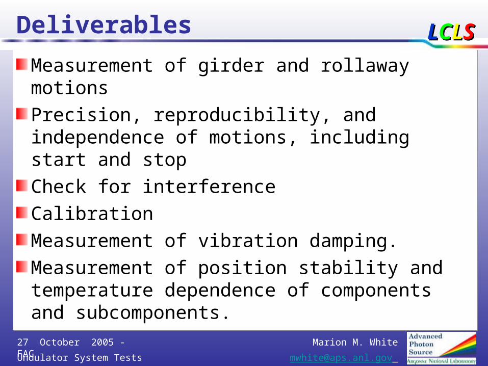
Deliverables
Measurement of girder and rollaway motions
Precision, reproducibility, and independence of motions, including start and stop
Check for interference
Calibration
Measurement of vibration damping.
Measurement of position stability and temperature dependence of components and subcomponents.

Marion M. White
Undulator System Tests [email protected]
27 October 2005 - FAC
LLCCLLSS• Quadrupole Motion Positioning Repeatability ±7 µm
• Short-Term (1 h) BPM / Quad Stability ±2 µm• Long-Term (24 h) BPM / Quad Stability ±5 µm
• Horiz. Segment Pos. Repeat. in Roll-Away Cycle ±10 µm• Vert. Segment Pos. Repeat. in Roll-Away Cycle ±5 µm
• Quad Transverse Position Change in Roll-Out ±25 µm• Quad Position Reproducibility after Roll-Away Cycle ±2 µm
• BPM Transverse Position Change in Roll-Out ±25 µm • BPM Position Reproducibility after Roll-Out Cycle ±2 µm
Requirements

Marion M. White
Undulator System Tests [email protected]
27 October 2005 - FAC
LLCCLLSSPrecision and repeatability of the cam-shaft system
vertically and transversely, measured @ undulator ends, for pitch and yaw motion as well.
Goal is ± 5µ specification ± 7µ;
Precision and repeatability of 80-mm transverse travel on the linear stages.
Goal is ± 10µ
Precision of the K-value adjustment using transverse linear stages.
Goal is ± 10µ
Short term stability (10 hours) of the girder and undulator.
Goal is ± 5µ; specification ± 5µ
Goals to Demonstrate

Marion M. White
Undulator System Tests [email protected]
27 October 2005 - FAC
LLCCLLSS
Components
Prototype undulator, or the substitute, or a 1st article if one is available and measured.
Prototype support/mover system: Girder, CAM movers, Rollaway system, controls software and hardware
Quadrupole Ersatz with fiducialization surfaces
BPM Ersatz with fiducialization surfaces
Vacuum Chamber Ersatz
WPM, HLS, BLM sensors or Ersatz
Prototype Fixed Support
Earthquake protection bracing – early prototype

Marion M. White
Undulator System Tests [email protected]
27 October 2005 - FAC
LLCCLLSS
Preparation @ ANL
Tests are done in the APS Magnet Measurement Area, MM1
Temperature regulated
May need a plastic tent to improve thermal regulation
Clean area
Adequate space
Experienced People
Well-known floor and mechanically stable area

Marion M. White
Undulator System Tests [email protected]
27 October 2005 - FAC
LLCCLLSS
A lot of work is done
A lot of work was already done using the breadboard girder, setting up the whole system, installing and learning to use the monitoring equipment, making improvements and design modifications, and writing control and monitoring software.
The results were surprisingly good, even for the rudimentary breadboard girder, so even better performance is expected in the real prototype.
Most designs are done, and most parts are on order or in-house for the test.

Marion M. White
Undulator System Tests [email protected]
27 October 2005 - FAC
LLCCLLSS
Prototype undulator at ANL on breadboard support/mover system

Marion M. White
Undulator System Tests [email protected]
27 October 2005 - FAC
LLCCLLSS
Prototype Girder
•Two rigid steel prototype girders are now being fabricated at Lynn Machine, near O’Hare airport in Chicago.
•One will be used for the integrated undulator test, and the other will be used for mechanical measurements without disturbing the undulator testing activities.
•The girders will be delivered to ANL by early November.

Marion M. White
Undulator System Tests [email protected]
27 October 2005 - FAC
LLCCLLSS
Improvements to the CAMs
Improvements were made to the CAMs as a result of information gained in the setup and learning phase.
Split bearing, hardness changed, spherical bearing, v-plate, more gear ratio, no brakes, …

Marion M. White
Undulator System Tests [email protected]
27 October 2005 - FAC
LLCCLLSS
•New gear box with ratio 250:1 is installed.
•Calculations show this ratio is enough to hold the undulator and girder in place without a brake.
•Less complexity.
Single CAM-shaft Mover

Marion M. White
Undulator System Tests [email protected]
27 October 2005 - FAC
LLCCLLSS
The same changes were implemented in this unit as in the single cam-shaft.
Double CAM-shaft Mover

Marion M. White
Undulator System Tests [email protected]
27 October 2005 - FAC
LLCCLLSS
Hardness of the rings on the ball-bearings was increased from
30-34 Rc to
50-55 Rc
Double CAM-shaft Mover (detail)

Marion M. White
Undulator System Tests [email protected]
27 October 2005 - FAC
LLCCLLSS
The flat pad is replaced by one with a “V” shape - 16 angle.
A double bearing is installed instead of the single bearing
Its purpose is to replace sliding friction by rolling friction.
Single CAM-shaft Mover working w/ “V” pad

Marion M. White
Undulator System Tests [email protected]
27 October 2005 - FAC
LLCCLLSS
Single CAM-shaft Mover

Marion M. White
Undulator System Tests [email protected]
27 October 2005 - FAC
LLCCLLSSUndulator substitute unit
expected 11/15New cam-shaft movers with new gear boxes
expected 11/25Modified transverse stages with 4” travel
in-houseMotors (in-house) and 90 gear boxes for stages
expected 10/31Transition plates, wedges and supporting parts
expected 11/25
Parts in-house by end of November
Marion M. White
Undulator System Tests [email protected]
27 October 2005 - FAC
LLCCLLSS
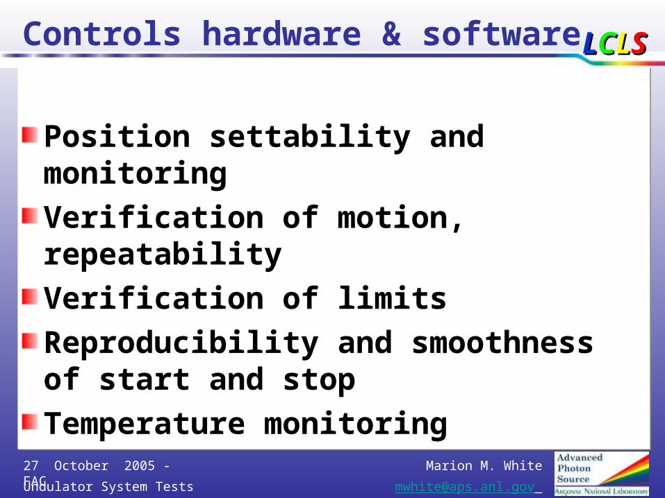
Controls hardware & software
Position settability and monitoring
Verification of motion, repeatability
Verification of limits
Reproducibility and smoothness of start and stop
Temperature monitoring
Marion M. White
Undulator System Tests [email protected]
27 October 2005 - FAC
LLCCLLSS
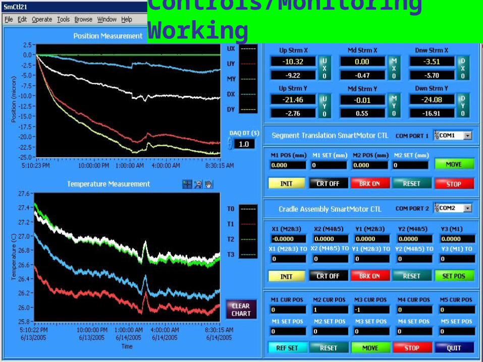
Controls/Monitoring Working

Marion M. White
Undulator System Tests [email protected]
27 October 2005 - FAC
LLCCLLSS
Case 1: X-Translation +/- 1.5 mm Cyclic Motion Repeatability
Location Laser Displacement Sensors
Linear Potentiometers
Upstream X ± 2.5 µm ± 1.5 µm
Upstream Y ± 1.0 µm ± 4.0 µm
Downstream X ± 2.0 µm ± 2.5 µm
Downstream Y ± 0.5 µm ± 4.0 µm
50
60
70
80
90
100
110
0 100 200 300 400 500 600 700 800
Laser Upstream X
Number of Cycles
X-Translation: +/- 1.5 mm Cyclic Motion Repeatability
Average Repeatability +/- 2.5 microns
Target Repeatability < +/- 7.0 µm
Marion M. White
Undulator System Tests [email protected]
27 October 2005 - FAC
LLCCLLSS
Fixed Support
ANL assumed the Fixed Support scope: a prototype will be designed, constructed, instrumented, and ready for evaluation as a part of this test.
The FDR will address the entire support/motion system, including the fixed supports.

Marion M. White
Undulator System Tests [email protected]
27 October 2005 - FAC
LLCCLLSS18” Support Tube
1½” Support Plates
Sand Filled
3” Wool Fiber Insulation
1½” Anchor Bolts
Fixed Support Design

Marion M. White
Undulator System Tests [email protected]
27 October 2005 - FAC
LLCCLLSS
Installation & AlignmentDesign for fixed supports takes alignment and installation into account – integration of alignment philosophy with SLAC is ongoing.
Marion M. White
Undulator System Tests [email protected]
27 October 2005 - FAC
LLCCLLSS
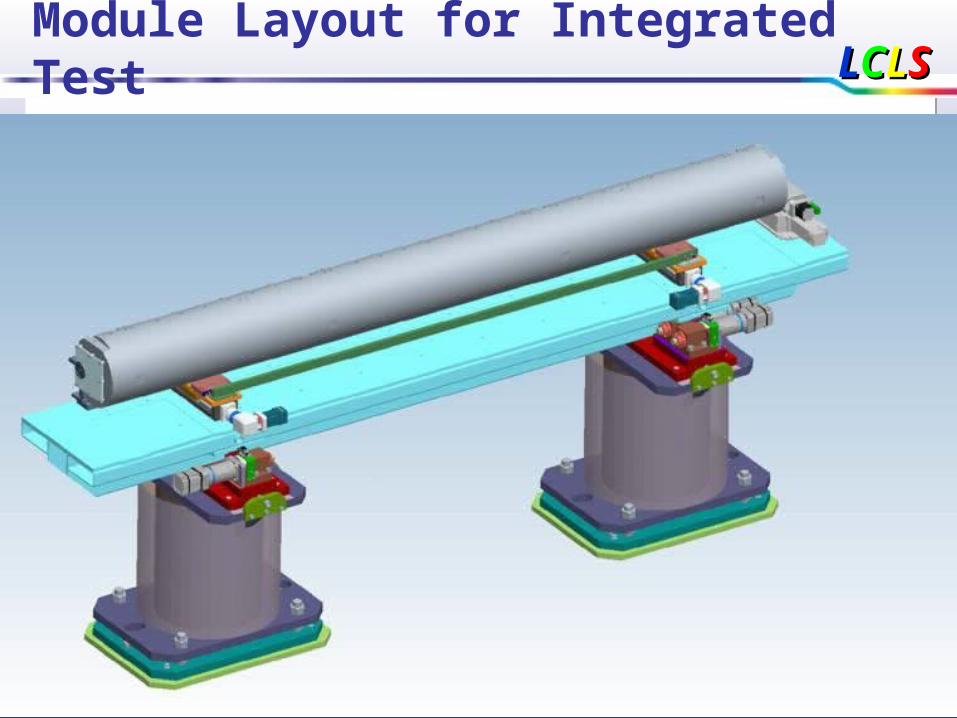
Module Layout for Integrated Test

Marion M. White
Undulator System Tests [email protected]
27 October 2005 - FAC
LLCCLLSS
Designs are well underway: Undulator on the girder (left end)

Marion M. White
Undulator System Tests [email protected]
27 October 2005 - FAC
LLCCLLSS
Designs: undulator on the girder (right end)

Marion M. White
Undulator System Tests [email protected]
27 October 2005 - FAC
LLCCLLSS
Use Ersatz Units as Needed
The quadrupole, BPM, and vacuum chamber are fiducialized Ersatz units with the right size and weight. Some real units are planned:
Pumping crosses and pumpsCabling, supports, and junctionsMagnet water pipingWPM, HLS, BLM sensors
Some kind of Earthquake bracing will be determined in collaboration with the SLAC safety committee, and will be incorporated; it may not be final

Marion M. White
Undulator System Tests [email protected]
27 October 2005 - FAC
LLCCLLSS
layout in short break;cartoon stages and stands

Marion M. White
Undulator System Tests [email protected]
27 October 2005 - FAC
LLCCLLSS
Earthquake bracing

Marion M. White
Undulator System Tests [email protected]
27 October 2005 - FAC
LLCCLLSS
Schedule
Design/procuring vacuum/diagnostic components
Developing detailed plan and refining engineering specifications.
Controls HW/SW demonstrated; debug/improve
Prepare/fabricate test stand and components August thru November 2005; On track to have many of the components by December 2005.
Assemble early CY-06
Short term test March 2006; leads to FDR; with longer-term 2-month test continuing after that.

Marion M. White
Undulator System Tests [email protected]
27 October 2005 - FAC
LLCCLLSS
Schedule Description Early Start Early Finish
Develop Plan & Base Design for Single Und Test 31-Aug-05 13-Oct-05Prepare Area for Single Undulator Test 15-Sep-05 27-Oct-05Prepare Ctrls HW/SW for Single Und Test 15-Sep-05 11-Nov-05Assemble Test/Meas/Verification Stand 04-Nov-05 13-Feb-06Prep for FDR - Supt/Mover System, Incl Ctrls Pkg 07-Mar-06 13-Mar-06Prototype Supt/Mover System w/Final Rqmts 06-Jan-06 06-Mar-06Assy of Fixed Supports at Integrated System Tst 07-Feb-06 13-Feb-06Mount Proto Und on PR S/M 07-Mar-06 09-Mar-06Assemble Module Components on Stand/Connect 10-Mar-06 23-Mar-06Carry out Short-Term Single Undulator Test 24-Mar-06 06-Apr-06Write Report: Short Term Test Results 07-Apr-06 20-Apr-06FDR - Supt/Mover System, Incl Controls Package 21-Apr-06 21-Apr-06Release RFP - Support/Mover System 21-Apr-06Release RFP for Pillar/Plates/Insulation 08-May-06

Marion M. White
Undulator System Tests [email protected]
27 October 2005 - FAC
LLCCLLSS
Summary
An undulator module test will be carried out at ANL in Winter 05-06 using prototype and substitute components.
The test will provide critical data for the support/mover system final design review prior to production.
Much work was already done in Fall 05, leading to improvements in system design, choice of components, and control.
Many parts are either in-house or on order.
Controls and monitoring software was written and already demonstrated and debugged. Calibration in progress.
Remaining hardware is expected in time.