Embed Size (px)
Citation preview

Lwin, M.M. "Floating Bridges." Bridge Engineering Handbook. Ed. Wai-Fah Chen and Lian Duan Boca Raton: CRC Press, 2000
22Floating Bridges
22.1 Introduction
22.2 Basic Concept
22.3 TypesFloating Structure • Anchoring Systems
22.4 Design CriteriaLoads and Load Combinations • Winds and Waves • Potential Damage • Control Progressive Failure • Design of Concrete Members • Anchoring System • Movable Span • Deflection and Motion
22.5 Structural Design and AnalysisPreliminary Design • Dynamic Analysis • Frequency-Domain Analysis
22.6 Fabrication and Construction
22.7 Construction Cost
22.8 Inspection, Maintenance, and Operation
22.9 Closing Remarks
22.1 Introduction
Floating bridges are cost-effective solutions for crossing large bodies of water with unusual depthand very soft bottom where conventional piers are impractical. For a site where the water is 2 to5 km wide, 30 to 60 m deep and there is a very soft bottom extending another 30 to 60 m, a floatingbridge is estimated to cost three to five times less than a long-span fixed bridge, tube, or tunnel.
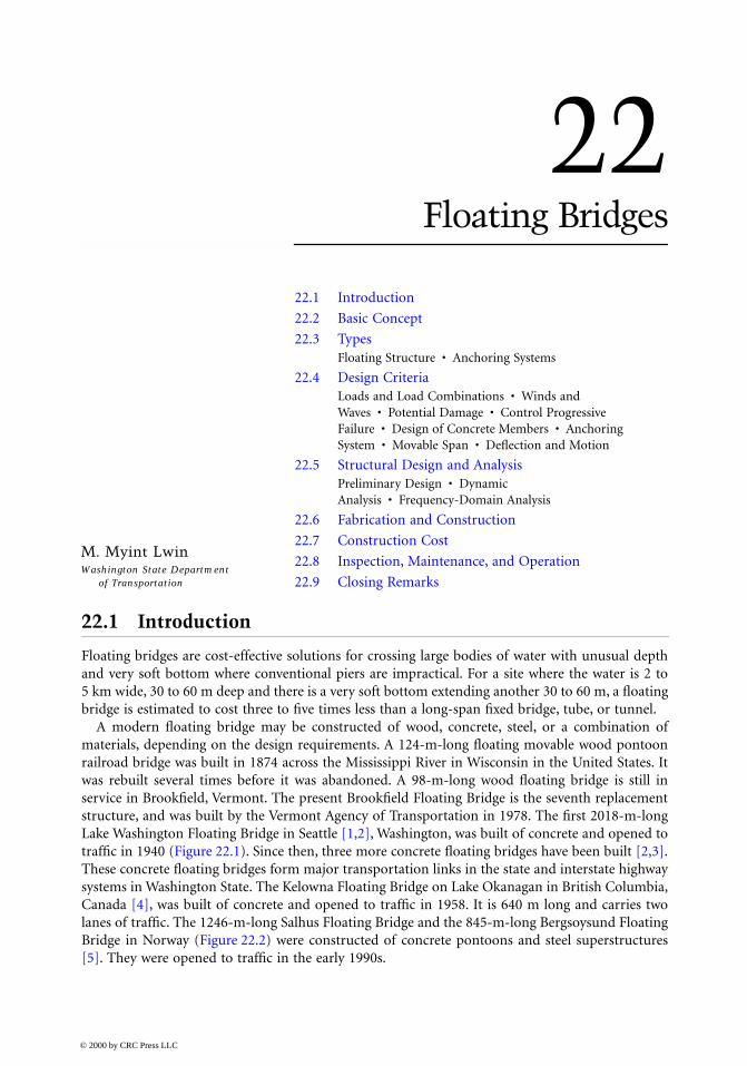
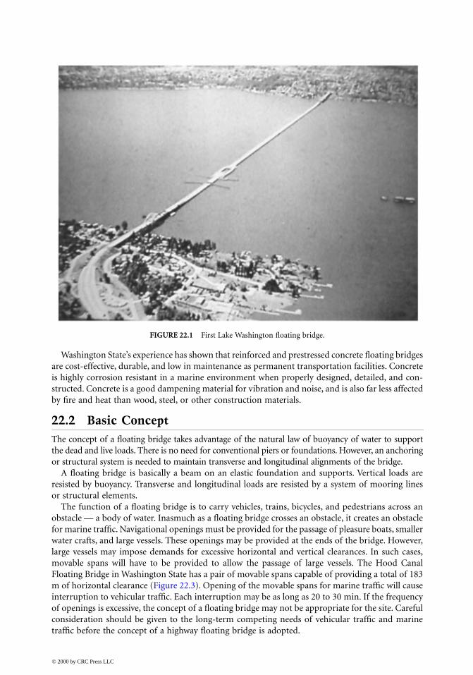
A modern floating bridge may be constructed of wood, concrete, steel, or a combination ofmaterials, depending on the design requirements. A 124-m-long floating movable wood pontoonrailroad bridge was built in 1874 across the Mississippi River in Wisconsin in the United States. Itwas rebuilt several times before it was abandoned. A 98-m-long wood floating bridge is still inservice in Brookfield, Vermont. The present Brookfield Floating Bridge is the seventh replacementstructure, and was built by the Vermont Agency of Transportation in 1978. The first 2018-m-longLake Washington Floating Bridge in Seattle [1,2], Washington, was built of concrete and opened totraffic in 1940 (Figure 22.1). Since then, three more concrete floating bridges have been built [2,3].These concrete floating bridges form major transportation links in the state and interstate highwaysystems in Washington State. The Kelowna Floating Bridge on Lake Okanagan in British Columbia,Canada [4], was built of concrete and opened to traffic in 1958. It is 640 m long and carries twolanes of traffic. The 1246-m-long Salhus Floating Bridge and the 845-m-long Bergsoysund FloatingBridge in Norway (Figure 22.2) were constructed of concrete pontoons and steel superstructures[5]. They were opened to traffic in the early 1990s.
M. Myint LwinWashington State Department
of Transportation
© 2000 by CRC Press LLC
Washington State’s experience has shown that reinforced and prestressed concrete floating bridgesare cost-effective, durable, and low in maintenance as permanent transportation facilities. Concreteis highly corrosion resistant in a marine environment when properly designed, detailed, and con-structed. Concrete is a good dampening material for vibration and noise, and is also far less affectedby fire and heat than wood, steel, or other construction materials.
22.2 Basic ConceptThe concept of a floating bridge takes advantage of the natural law of buoyancy of water to supportthe dead and live loads. There is no need for conventional piers or foundations. However, an anchoringor structural system is needed to maintain transverse and longitudinal alignments of the bridge.
A floating bridge is basically a beam on an elastic foundation and supports. Vertical loads areresisted by buoyancy. Transverse and longitudinal loads are resisted by a system of mooring linesor structural elements.
The function of a floating bridge is to carry vehicles, trains, bicycles, and pedestrians across anobstacle — a body of water. Inasmuch as a floating bridge crosses an obstacle, it creates an obstaclefor marine traffic. Navigational openings must be provided for the passage of pleasure boats, smallerwater crafts, and large vessels. These openings may be provided at the ends of the bridge. However,large vessels may impose demands for excessive horizontal and vertical clearances. In such cases,movable spans will have to be provided to allow the passage of large vessels. The Hood CanalFloating Bridge in Washington State has a pair of movable spans capable of providing a total of 183m of horizontal clearance (Figure 22.3). Opening of the movable spans for marine traffic will causeinterruption to vehicular traffic. Each interruption may be as long as 20 to 30 min. If the frequencyof openings is excessive, the concept of a floating bridge may not be appropriate for the site. Carefulconsideration should be given to the long-term competing needs of vehicular traffic and marinetraffic before the concept of a highway floating bridge is adopted.
FIGURE 22.1 First Lake Washington floating bridge.
© 2000 by CRC Press LLC
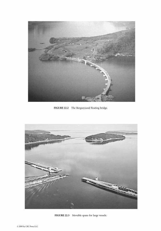
FIGURE 22.2 The Bergsoysund floating bridge.
FIGURE 22.3 Movable spans for large vessels.
© 2000 by CRC Press LLC
22.3 Types
22.3.1 Floating Structure
Floating bridges have been built since time immemorial. Ancient floating bridges were generallybuilt for military operations [6]. All of these bridges took the form of small vessels placed side byside with wooden planks used as a roadway. Subsequently, designers added openings for the passageof small boats, movable spans for the passage of large ships, variable flotation to adjust for changein elevations, and so on.
Modern floating bridges generally consist of concrete pontoons with or without an elevated super-structure of concrete or steel. The pontoons may be reinforced concrete or prestressed concrete post-tensioned in one or more directions. They can be classified into two types, namely, the continuouspontoon type and the separate pontoon type. Openings for the passage of small boats and movablespans for large vessels can be incorporated into each of the two types of modern floating bridges.
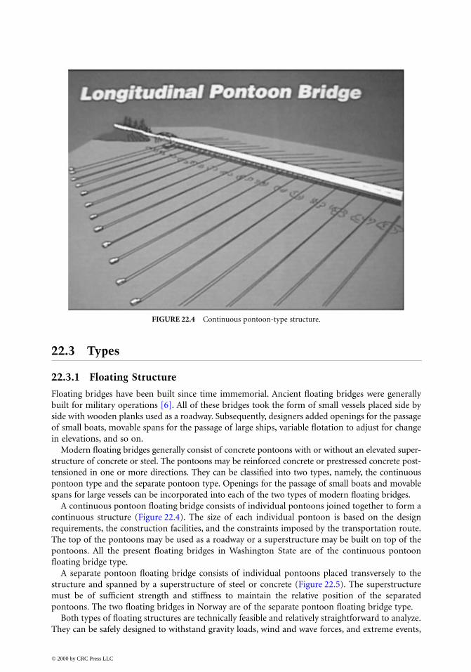
A continuous pontoon floating bridge consists of individual pontoons joined together to form acontinuous structure (Figure 22.4). The size of each individual pontoon is based on the designrequirements, the construction facilities, and the constraints imposed by the transportation route.The top of the pontoons may be used as a roadway or a superstructure may be built on top of thepontoons. All the present floating bridges in Washington State are of the continuous pontoonfloating bridge type.
A separate pontoon floating bridge consists of individual pontoons placed transversely to thestructure and spanned by a superstructure of steel or concrete (Figure 22.5). The superstructuremust be of sufficient strength and stiffness to maintain the relative position of the separatedpontoons. The two floating bridges in Norway are of the separate pontoon floating bridge type.
Both types of floating structures are technically feasible and relatively straightforward to analyze.They can be safely designed to withstand gravity loads, wind and wave forces, and extreme events,
FIGURE 22.4 Continuous pontoon-type structure.
© 2000 by CRC Press LLC
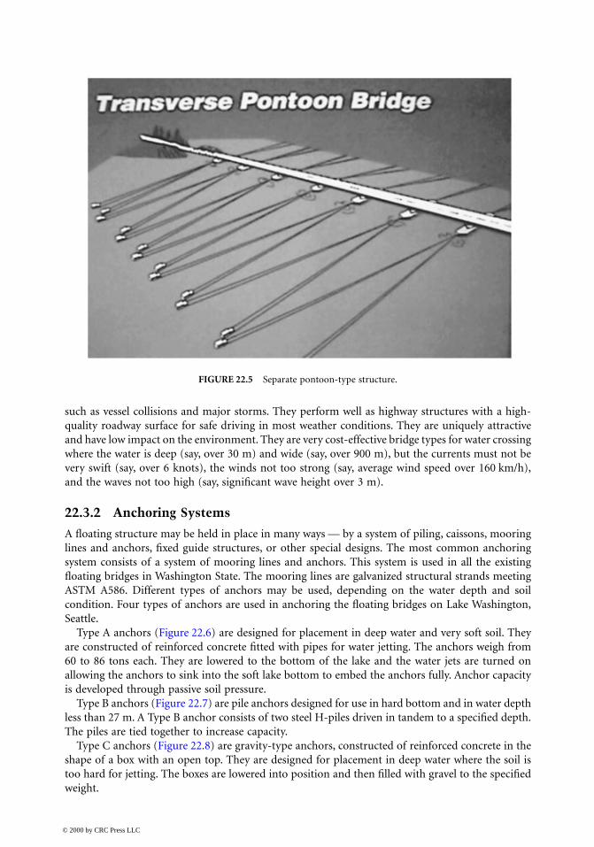
such as vessel collisions and major storms. They perform well as highway structures with a high-quality roadway surface for safe driving in most weather conditions. They are uniquely attractiveand have low impact on the environment. They are very cost-effective bridge types for water crossingwhere the water is deep (say, over 30 m) and wide (say, over 900 m), but the currents must not bevery swift (say, over 6 knots), the winds not too strong (say, average wind speed over 160 km/h),and the waves not too high (say, significant wave height over 3 m).
22.3.2 Anchoring Systems
A floating structure may be held in place in many ways — by a system of piling, caissons, mooringlines and anchors, fixed guide structures, or other special designs. The most common anchoringsystem consists of a system of mooring lines and anchors. This system is used in all the existingfloating bridges in Washington State. The mooring lines are galvanized structural strands meetingASTM A586. Different types of anchors may be used, depending on the water depth and soilcondition. Four types of anchors are used in anchoring the floating bridges on Lake Washington,Seattle.
Type A anchors (Figure 22.6) are designed for placement in deep water and very soft soil. Theyare constructed of reinforced concrete fitted with pipes for water jetting. The anchors weigh from60 to 86 tons each. They are lowered to the bottom of the lake and the water jets are turned onallowing the anchors to sink into the soft lake bottom to embed the anchors fully. Anchor capacityis developed through passive soil pressure.
Type B anchors (Figure 22.7) are pile anchors designed for use in hard bottom and in water depthless than 27 m. A Type B anchor consists of two steel H-piles driven in tandem to a specified depth.The piles are tied together to increase capacity.
Type C anchors (Figure 22.8) are gravity-type anchors, constructed of reinforced concrete in theshape of a box with an open top. They are designed for placement in deep water where the soil istoo hard for jetting. The boxes are lowered into position and then filled with gravel to the specifiedweight.
FIGURE 22.5 Separate pontoon-type structure.
© 2000 by CRC Press LLC
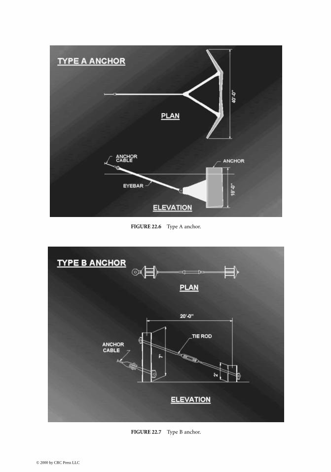
FIGURE 22.6 Type A anchor.
FIGURE 22.7 Type B anchor.
© 2000 by CRC Press LLC
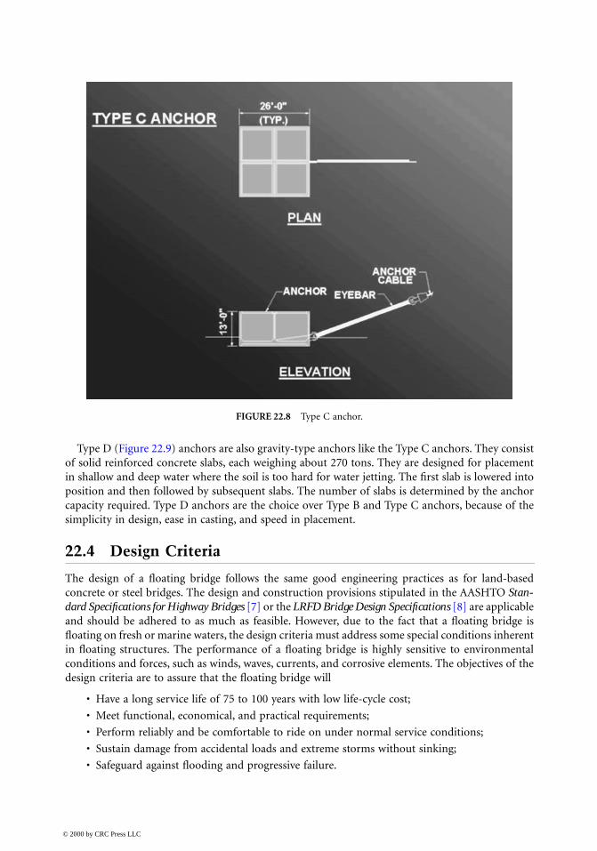
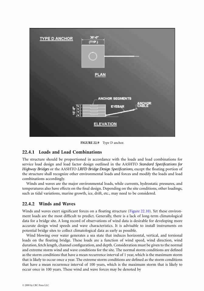
Type D (Figure 22.9) anchors are also gravity-type anchors like the Type C anchors. They consistof solid reinforced concrete slabs, each weighing about 270 tons. They are designed for placementin shallow and deep water where the soil is too hard for water jetting. The first slab is lowered intoposition and then followed by subsequent slabs. The number of slabs is determined by the anchorcapacity required. Type D anchors are the choice over Type B and Type C anchors, because of thesimplicity in design, ease in casting, and speed in placement.
22.4 Design Criteria
The design of a floating bridge follows the same good engineering practices as for land-basedconcrete or steel bridges. The design and construction provisions stipulated in the AASHTO Stan-dard Specifications for Highway Bridges [7] or the LRFD Bridge Design Specifications [8] are applicableand should be adhered to as much as feasible. However, due to the fact that a floating bridge isfloating on fresh or marine waters, the design criteria must address some special conditions inherentin floating structures. The performance of a floating bridge is highly sensitive to environmentalconditions and forces, such as winds, waves, currents, and corrosive elements. The objectives of thedesign criteria are to assure that the floating bridge will
• Have a long service life of 75 to 100 years with low life-cycle cost;
• Meet functional, economical, and practical requirements;
• Perform reliably and be comfortable to ride on under normal service conditions;
• Sustain damage from accidental loads and extreme storms without sinking;
• Safeguard against flooding and progressive failure.
FIGURE 22.8 Type C anchor.
© 2000 by CRC Press LLC
22.4.1 Loads and Load Combinations
The structure should be proportioned in accordance with the loads and load combinations forservice load design and load factor design outlined in the AASHTO Standard Specifications forHighway Bridges or the AASHTO LRFD Bridge Design Specifications, except the floating portion ofthe structure shall recognize other environmental loads and forces and modify the loads and loadcombinations accordingly.
Winds and waves are the major environmental loads, while currents, hydrostatic pressures, andtemperatures also have effects on the final design. Depending on the site conditions, other loadings,such as tidal variations, marine growth, ice, drift, etc., may need to be considered.
22.4.2 Winds and Waves
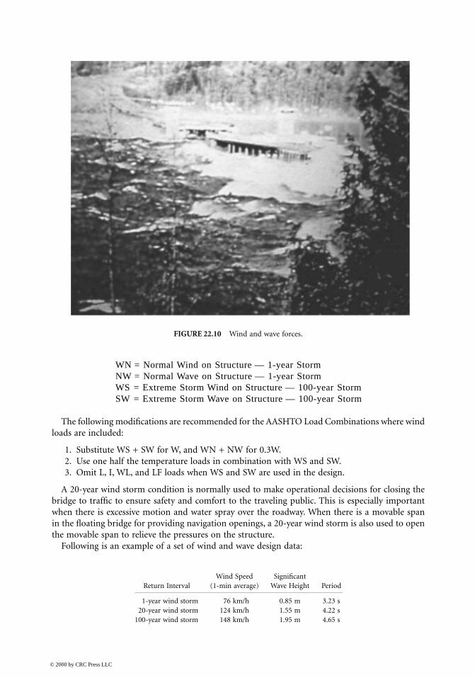
Winds and waves exert significant forces on a floating structure (Figure 22.10). Yet these environ-ment loads are the most difficult to predict. Generally, there is a lack of long-term climatologicaldata for a bridge site. A long record of observations of wind data is desirable for developing moreaccurate design wind speeds and wave characteristics. It is advisable to install instruments onpotential bridge sites to collect climatological data as early as possible.
Wind blowing over water generates a sea state that induces horizontal, vertical, and torsionalloads on the floating bridge. These loads are a function of wind speed, wind direction, windduration, fetch length, channel configuration, and depth. Consideration must be given to the normaland extreme storm wind and wave conditions for the site. The normal storm conditions are definedas the storm conditions that have a mean recurrence interval of 1 year, which is the maximum stormthat is likely to occur once a year. The extreme storm conditions are defined as the storm conditionsthat have a mean recurrence interval of 100 years, which is the maximum storm that is likely tooccur once in 100 years. These wind and wave forces may be denoted by
FIGURE 22.9 Type D anchor.
© 2000 by CRC Press LLC
WN = Normal Wind on Structure — 1-year StormNW = Normal Wave on Structure — 1-year StormWS = Extreme Storm Wind on Structure — 100-year StormSW = Extreme Storm Wave on Structure — 100-year Storm
The following modifications are recommended for the AASHTO Load Combinations where windloads are included:
1. Substitute WS + SW for W, and WN + NW for 0.3W.2. Use one half the temperature loads in combination with WS and SW.3. Omit L, I, WL, and LF loads when WS and SW are used in the design.
A 20-year wind storm condition is normally used to make operational decisions for closing thebridge to traffic to ensure safety and comfort to the traveling public. This is especially importantwhen there is excessive motion and water spray over the roadway. When there is a movable spanin the floating bridge for providing navigation openings, a 20-year wind storm is also used to openthe movable span to relieve the pressures on the structure.
Following is an example of a set of wind and wave design data:
FIGURE 22.10 Wind and wave forces.
Wind Speed SignificantReturn Interval (1-min average) Wave Height Period
1-year wind storm 76 km/h 0.85 m 3.23 s20-year wind storm 124 km/h 1.55 m 4.22 s
100-year wind storm 148 km/h 1.95 m 4.65 s
© 2000 by CRC Press LLC
22.4.3 Potential Damage
A floating bridge must have adequate capacity to safely sustain potential damages (DM) resultingfrom small vessel collision, debris or log impact, flooding, and loss of a mooring cable or component.Considering only one damage condition and location at any one time, the pontoon structure mustbe designed for at least the following:
1. Collision: Apply a 45-kN horizontal collision load as a service load to the pontoon exteriorwalls. Apply a 130-kN horizontal collision load as a factored load to the pontoon exteriorwall. The load may be assumed to be applied to an area no greater than 0.3 × 0.3 m.
2. Flooding:
• Flooding of any two adjacent exterior cells along the length of the structure
• Flooding of all cells across the width of the pontoon
• Flooding of all the end cells of an isolated pontoon during towing
• Flooding of the outboard end cells of a partially assembled structure
3. Loss of a mooring cable or component.4. Complete separation of the floating bridge by a transverse or diagonal fracture. This condition
should apply to the factored load combinations only.
The above potential DM loadings should be combined with the AASHTO Groups VI, VIII, andIX combinations for Service Load Design and Load Factor Design. If the AASHTO LRFD BridgeDesign Specifications are used in the design, the loads from Items 2 to 4 may be considered asextreme events.
Every floating structure is unique and specific requirements must be established accordingly.Maritime damage criteria and practices, such as those for ships and passenger vessels, should bereviewed and applied where applicable in developing damage criteria for a floating structure.However, a floating bridge behaves quite differently than a vessel, in that structural restraint is muchmore dominant than hydrostatic restraint. The trim, list, and sinkage of the flooded structure arerelatively small. With major damage, structural capacity is reached before large deformationsoccurred or were observed. This is an important fact to note when comparing with stability criteriafor ships.
22.4.4 Control Progressive Failure
While water provides buoyancy to keep a floating bridge afloat, water leaking into the interior of afloating bridge can cause progressive failure, eventually sinking the bridge. Time is of the essencewhen responding to damage or flooding. Maintenance personnel must respond to damage of afloating bridge quickly, especially when water begins to leak into the structure. An electronic cellmonitoring system with water sensors to detect water entry and provide early warning to themaintenance personnel should be installed to assure timely emergency response. A bilge pipingsystem should also be installed in the bridge for pumping out water.
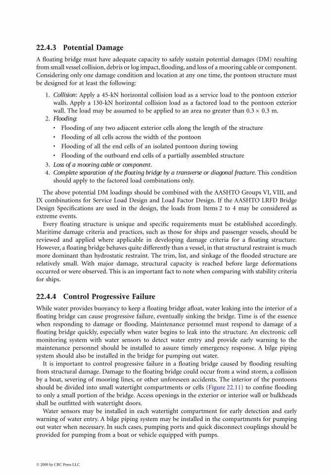
It is important to control progressive failure in a floating bridge caused by flooding resultingfrom structural damage. Damage to the floating bridge could occur from a wind storm, a collisionby a boat, severing of mooring lines, or other unforeseen accidents. The interior of the pontoonsshould be divided into small watertight compartments or cells (Figure 22.11) to confine floodingto only a small portion of the bridge. Access openings in the exterior or interior wall or bulkheadsshall be outfitted with watertight doors.
Water sensors may be installed in each watertight compartment for early detection and earlywarning of water entry. A bilge piping system may be installed in the compartments for pumpingout water when necessary. In such cases, pumping ports and quick disconnect couplings should beprovided for pumping from a boat or vehicle equipped with pumps.
© 2000 by CRC Press LLC
22.4.5 Design of Concrete Members
The design of reinforced concrete members should be based on behavior at service load conditionsas per AASHTO Standard Specifications, or the service limit state as per AASHTO LRFD BridgeDesign Specifications; except sections where reinforcement is to resist sustained hydrostatic forcesthe allowable stress in the reinforcing steel should not exceed 97 Mpa to limit crack width to amaximum of 0.10mm.
Prestressed members should be designed under the applicable service load and load factor pro-visions in the AASHTO Standard Specifications or the limit states provisions in the AASHTO LRFDBridge Design Specifications, except the allowable concrete tensile stress under final conditions inthe precompressed tensile zone should be limited to zero.
The ultimate flexural strength of the overall pontoon section should be computed for a maximumcrack width of 0.25 mm and should not be less than the loads from the factored load combinationsor 1.3 times the cracking moment, Mcr.
In a moderate climate, the following temperature differentials between the various portions of afloating bridge may be used:
1. Between the exposed portion and the submerged portion of a pontoon: ±19°C. The exposedportion may be considered as the top slab, and the remaining part of the pontoon as sub-merged. If the top slab is shaded by an elevated structure, the differential temperature maybe reduced to ±14°C
2. Between the top slab and the elevated structure of the pontoon: ±14°C
The effects of creep and shrinkage should be considered while the pontoons are in the dry only.Creep and shrinkage may be taken as zero once the pontoons are launched. The time-dependenteffects of creep and shrinkage may be estimated in accordance with the AASHTO Specifications. Afinal differential shrinkage coefficient of 0.0002 should be considered between the lower portion ofthe pontoon and the top slab of the pontoon.
High-performance concrete containing fly ash and silica fume is most suitable for floating bridges[9,10]. The concrete is very dense, impermeable to water, highly resistant to abrasion, and relatively
FIGURE 22.11 Small watertight compartments.
© 2000 by CRC Press LLC
crack free. High-performance concrete also has high strength, low creep, and low shrinkage.Concrete mixes may be customized for the project.
Recommended minimum concrete cover of reinforcing steel:
22.4.6 Anchoring System
An anchoring system should be installed in the floating bridge to maintain transverse and horizontalalignment. The anchoring system should be designed to have adequate capacity to resist transverseand longitudinal forces from winds, waves, and current.
Adequate factors of safety or load and resistance factors consistent with the type of anchoringshould be included in the design of the components of the system.
22.4.7 Movable Span
A floating bridge creates an obstruction to marine traffic. Movable spans may need to be providedfor the passage of large vessels. The width of opening that must be provided depends on the sizeand type of vessels navigating through the opening. Movable spans of up to a total opening of 190m have been used.
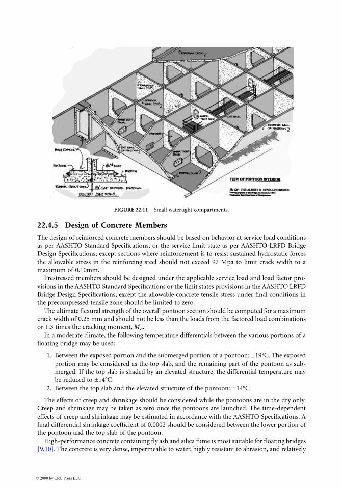
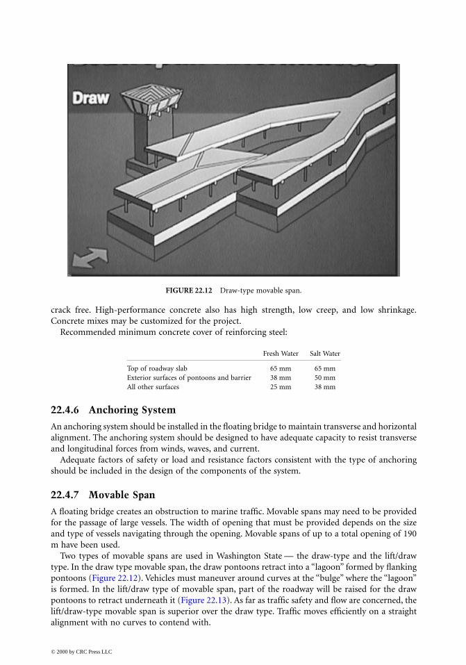
Two types of movable spans are used in Washington State — the draw-type and the lift/drawtype. In the draw type movable span, the draw pontoons retract into a “lagoon” formed by flankingpontoons (Figure 22.12). Vehicles must maneuver around curves at the “bulge” where the “lagoon”is formed. In the lift/draw type of movable span, part of the roadway will be raised for the drawpontoons to retract underneath it (Figure 22.13). As far as traffic safety and flow are concerned, thelift/draw-type movable span is superior over the draw type. Traffic moves efficiently on a straightalignment with no curves to contend with.
FIGURE 22.12 Draw-type movable span.
Fresh Water Salt Water
Top of roadway slab 65 mm 65 mmExterior surfaces of pontoons and barrier 38 mm 50 mmAll other surfaces 25 mm 38 mm
© 2000 by CRC Press LLC
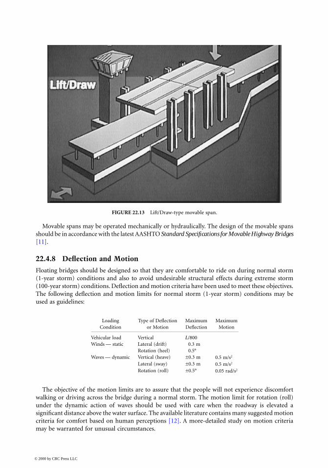
Movable spans may be operated mechanically or hydraulically. The design of the movable spansshould be in accordance with the latest AASHTO Standard Specifications for Movable Highway Bridges[11].
22.4.8 Deflection and Motion
Floating bridges should be designed so that they are comfortable to ride on during normal storm(1-year storm) conditions and also to avoid undesirable structural effects during extreme storm(100-year storm) conditions. Deflection and motion criteria have been used to meet these objectives.The following deflection and motion limits for normal storm (1-year storm) conditions may beused as guidelines:
The objective of the motion limits are to assure that the people will not experience discomfortwalking or driving across the bridge during a normal storm. The motion limit for rotation (roll)under the dynamic action of waves should be used with care when the roadway is elevated asignificant distance above the water surface. The available literature contains many suggested motioncriteria for comfort based on human perceptions [12]. A more-detailed study on motion criteriamay be warranted for unusual circumstances.
FIGURE 22.13 Lift/Draw-type movable span.
Loading Type of Deflection Maximum MaximumCondition or Motion Deflection Motion
Vehicular load Vertical L/800Winds — static Lateral (drift) 0.3 m
Rotation (heel) 0.5°Waves — dynamic Vertical (heave) ±0.3 m 0.5 m/s2
Lateral (sway) ±0.3 m 0.5 m/s2
Rotation (roll) ±0.5° 0.05 rad/s2
© 2000 by CRC Press LLC
22.5 Structural Design and Analysis
The design and analysis of floating bridges have gone through several stages of progressive devel-opment since the first highway floating bridge was designed and built in the late 1930s across LakeWashington, Seattle. The design has advanced from empirical methods to realistic approach, fromthe equivalent static approach to dynamic analysis, from computer modeling to physical modeltesting, and from reinforced concrete to prestressed concrete.
The most difficult part of early designs was the prediction of winds and waves, and the responsedue to wind–wave–structure interaction. Climatological data were very limited. Thewind–wave–structure interaction was not well understood. Current state of the knowledge in atmo-spheric sciences, computer science, marine engineering, finite-element analysis, structural engineer-ing, and physical model testing provides more accurate prediction of wind and wave climatology,more realistic dynamic analysis of wind–wave–structure interactions, and more reliable designs.
Designing for static loads, such as dead and live loads, is very straightforward using the classicaltheory on beam on elastic foundation [13]. For example, the maximum shear, moment, anddeflection due to a concentrated load, P, acting away from the end of a continuous floating structureare given by
(22.1)
(22.2)
(22.3)
where k = modulus of foundation
Designing for the response of the structure to winds and waves is more complex, because of therandom nature of these environment loads. To determine the dynamic response of the bridge towind generated waves realistically, a dynamic analysis is necessary.
22.5.1 Preliminary Design
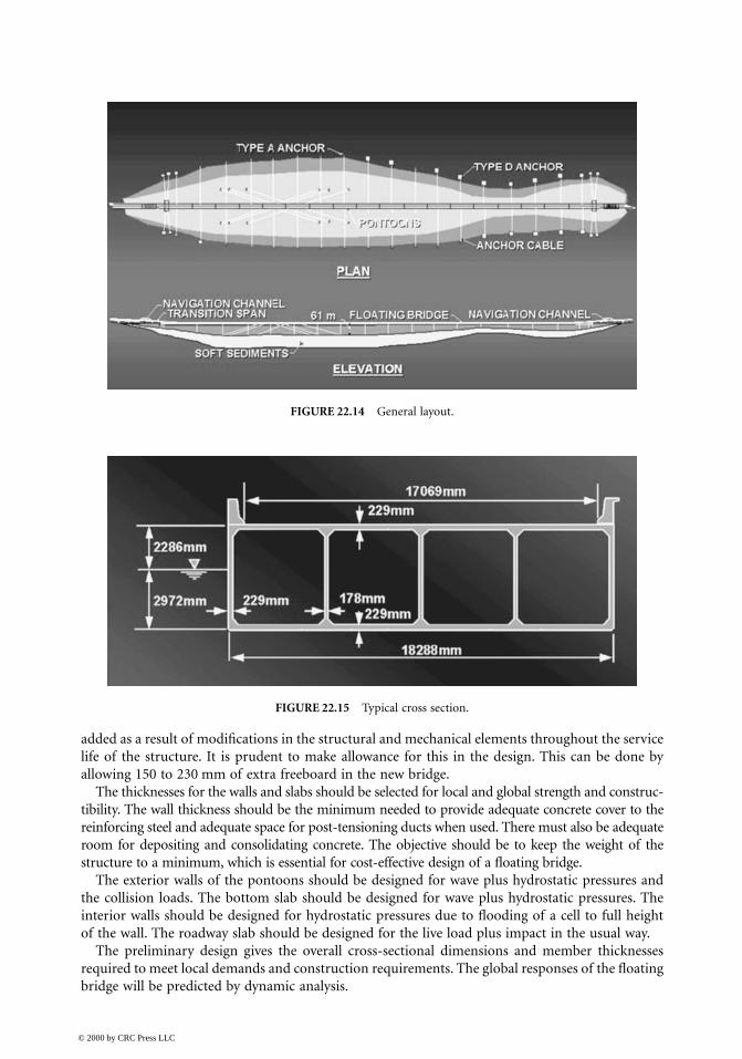
The design starts with selecting the type, size, and location of the floating bridge (Figure 22.14).Assuming a concrete box section of cellular construction with dimensions as shown in Figure 22.15,the first step is to determine the freeboard required. The height of the freeboard is selected to avoidwater spray on the roadway deck from normal storms. The draft can then be determined as necessaryto provide the selected freeboard.
The freeboard and draft of the floating structure should be calculated based on the weight ofconcrete, weight of reinforcing steel, weight of appurtenances, weight of marine growth as appro-priate, and vertical component of anchor cable force. The weight of the constructed pontoon isgenerally heavier than the computed weight, because of form bulging and other constructiontolerances. Based on the experience in Washington State, the weight increase varies from 3 to 5%of the theoretical weight. This increase should be included in the draft calculation. Additionally,floating pontoons experience loss in freeboard in the long term. The main reason is due to weight
VP
max =2
MP
max =4λ
yP
kmax = λ2
λ = 44
kEI
© 2000 by CRC Press LLC
added as a result of modifications in the structural and mechanical elements throughout the servicelife of the structure. It is prudent to make allowance for this in the design. This can be done byallowing 150 to 230 mm of extra freeboard in the new bridge.
The thicknesses for the walls and slabs should be selected for local and global strength and construc-tibility. The wall thickness should be the minimum needed to provide adequate concrete cover to thereinforcing steel and adequate space for post-tensioning ducts when used. There must also be adequateroom for depositing and consolidating concrete. The objective should be to keep the weight of thestructure to a minimum, which is essential for cost-effective design of a floating bridge.
The exterior walls of the pontoons should be designed for wave plus hydrostatic pressures andthe collision loads. The bottom slab should be designed for wave plus hydrostatic pressures. Theinterior walls should be designed for hydrostatic pressures due to flooding of a cell to full heightof the wall. The roadway slab should be designed for the live load plus impact in the usual way.
The preliminary design gives the overall cross-sectional dimensions and member thicknessesrequired to meet local demands and construction requirements. The global responses of the floatingbridge will be predicted by dynamic analysis.
FIGURE 22.14 General layout.
FIGURE 22.15 Typical cross section.
© 2000 by CRC Press LLC

22.5.2 Dynamic Analysis
The basic approach to dynamic analysis is to solve the equation of motion:
(22.4)
This equation is familiar to structural engineering in solving most structural dynamic problemsof land-based structures. However, in predicting the dynamic response of a floating bridge, theeffects of water–structure interaction must be accounted for in the analysis. As a floating bridgeresponds to the incident waves, the motions (heave, sway, and roll) of the bridge produce hydro-dynamic effects generally characterized in terms of added mass and damping coefficients. Thesehydrodynamic coefficients are frequency dependent. The equation of motion for a floating structuretakes on the general form:
(22.5)
whereX, = generalized displacement, velocity and acceleration at each degree of freedomM = mass–inertia matrix of the structureA = added mass matrix (frequency dependent)C1 = structural damping coefficientC2 = hydrodynamic damping coefficient (frequency dependent)K = structural stiffness matrix (elastic properties, including effects of mooring lines when used)k = hydrostatic stiffness (hydrostatic restoring forces)F(t) = forces acting on the structure
A substantial amount of experimental data has been obtained for the hydrodynamic coefficientsfor ships and barges [14,15]. Based on these experimental data, numerical methods and computerprograms have been developed for computing hydrodynamic coefficients of commonly used cross-sectional shapes, such as the rectangular shape. For structural configurations for which no or limiteddata exist, physical model testing will be necessary to determine the basic sectional added mass,damping, and wave excitation loads.
Structural damping is an important source of damping in the structure. It significantly affectsthe responses. A structural damping coefficient of 2 to 5% of critical damping is generally assumedfor the analysis. It is recommended that a better assessment of the damping coefficient be made tobetter represent the materials and structural system used in the final design.
The significant wave height, period, and central heading angle may be predicted using the publicdomain program NARFET developed by the U.S. Army Coastal Engineering Research Center[16,17]. This program accounts for the effective fetch to a location on the floating structure by aset of radial fetch lines to the point of interest. The Joint North Sea Wave Project (JONSWAP)spectrum is commonly used to represent the frequency distribution of the wave energy predictedby the program NARFET. This spectrum is considered to represent fetch-limited site conditionsvery well. A spreading function is used to distribute the energy over a range of angles of departurefrom the major storm heading to the total energy [18]. The spreading function takes the form ofan even cosine function, cos2n θ, where θ is the angle of the incident wave with respect to the centralheading angle. Usually 2n is 2 or greater. 2n = 2 is generally used for ocean structures where thestructures are relatively small with respect to the open sea. In the case of a floating bridge, the bridgelength is very large in comparison to the body of water, resulting in very little energy distributedaway from the central heading angle. A larger number of 2n will have to be used for a floatingbridge. The larger the number of 2n the more focused the wave direction near the central heading
MX CX KX F t˙̇ ˙̇+ + = ( )
M A X C C X K k X F t+[ ] + +[ ] + +[ ] = ( )˙̇ ˙1 2
˙ , ˙̇X X
© 2000 by CRC Press LLC
angle. A 2n value of 12 to 16 have been used in analyzing the floating bridges in Washington State.The value of 2n should be selected with care to reflect properly the site condition and the wind andwave directions.
The equation of motion may be solved by the time-domain (deterministic) analysis or thefrequency-domain (probabilistic) analysis. The time-domain approach involves solving differen-tial equations when the coefficients are constants. The equations become very complex when thecoefficients are frequency dependent. This method is tedious and time-consuming. The fre-quency-domain approach is very efficient in handling constant and frequency-dependent coeffi-cients. The equations are algebraic equations. However, time-dependent coefficients are notadmissible and nonlinearities will have to be linearized by approximation. For the dynamicanalysis of floating bridges subjected to the random nature of environmental forces and thefrequency-dependent hydrodynamic coefficients, frequency-domain analysis involves only simpleand fast calculations.
22.5.3 Frequency-Domain Analysis
The frequency-domain dynamic analysis is based on the principles of naval architecture and thestrip theory developed for use in predicting the response of ships to sea loads [19,20]. The essenceof this approach is the assumption that the flow at one section through the structure does not affectthe flow at any other section. Additional assumptions are (1) the motions are relatively small, (2)the fluid is incompressible and invisid, and (3) the flow is irrotational. By using the strip theory,the problem of wave–structure interaction can be solved by applying the equation of motion in thefrequency domain [21,22]. By Fourier transform, the equation of motion may be expressed in termsof frequencies, ω, as follows:
(22.6)
This equation may be solved as a set of algebraic equations at each frequency and the responsesdetermined. The maximum bending moments, shears, torsion, deflections, and rotations can thenbe predicted using spectral analysis and probability distribution [23,24]. The basic steps involvedin a frequency-domain analysis are
1. Compute the physical properties of the bridge — geometry of the bridge elements, sectionproperties, connections between bridge elements, mass–inertia, linearized spring constants,structural damping, etc.
2. Compute hydrodynamic coefficients — frequency-dependent added mass and frequency-dependent damping.
3. Compute hydrostatic stiffnesses.4. Calculate wind, wave, and current loads, and other loading terms.5. Build a finite-element computer model of the bridge [25] as a collection of nodes, beam
elements, and spring elements. The nodes form the joints connecting the beam elements andthe spring elements, and each node has six degrees of freedom.
6. Solve the equation of motion in the frequency domain to obtain frequency responses, themagnitudes of which are referred to as response amplitude operators (RAOs).
7. Perform spectral analysis, using the RAOs and the input sea spectrum, to obtain the rootmean square (RMS) of responses.
8. Perform probability analysis to obtain the maximum values of the responses with the desiredprobability of being exceeded.
9. Combine the maximum responses with other loadings, such as wind, current, etc., for finaldesign.
− +[ ] + +[ ] + +[ ]{ } = ( ){ }ω ω ω21 2M A i C C K k F
© 2000 by CRC Press LLC
22.6 Fabrication and Construction
Concrete pontoons are generally used for building major floating bridges. The fabrication andconstruction of the concrete pontoons must follow the best current practices in structural andmarine engineering in concrete design, fabrication, and construction, with added emphasis on high-quality concrete and watertightness. Quality control should be the responsibility of the fabrica-tors/contractors. Final quality assurance and acceptance should be the responsibility of the owners.In addition to these traditional divisions of responsibilities, the construction of a floating bridgenecessitates a strong “partnership” arrangement to work together, contracting agencies and con-tractors, to provide full cooperation and joint training, share knowledge and expertise, share respon-sibility, and to help each other succeed in building a quality floating bridge. The contractors shouldhave experience in marine construction and engage the services of naval architects or marineengineers to develop plans for monitoring construction activities and identifying flood risks, andprepare contingency plans for mitigating the risks.
Knowledge is power and safety. The construction personnel, including inspectors from the con-tracting agencies and the contractors, should be trained on the background of the contract require-ments and the actions necessary to implement the requirements fully. Their understanding andcommitment are necessary for complete and full compliance with contract requirements that bearon personal and bridge safety.
Construction of floating bridges is well established. Many concrete floating bridges have beenbuilt successfully using cast-in-place, precast, or a combination of cast-in-place and precast methods.Construction techniques are well developed and reported in the literature. Owners of floatingbridges have construction specifications and other documents and guidelines for the design andconstruction of such structures.
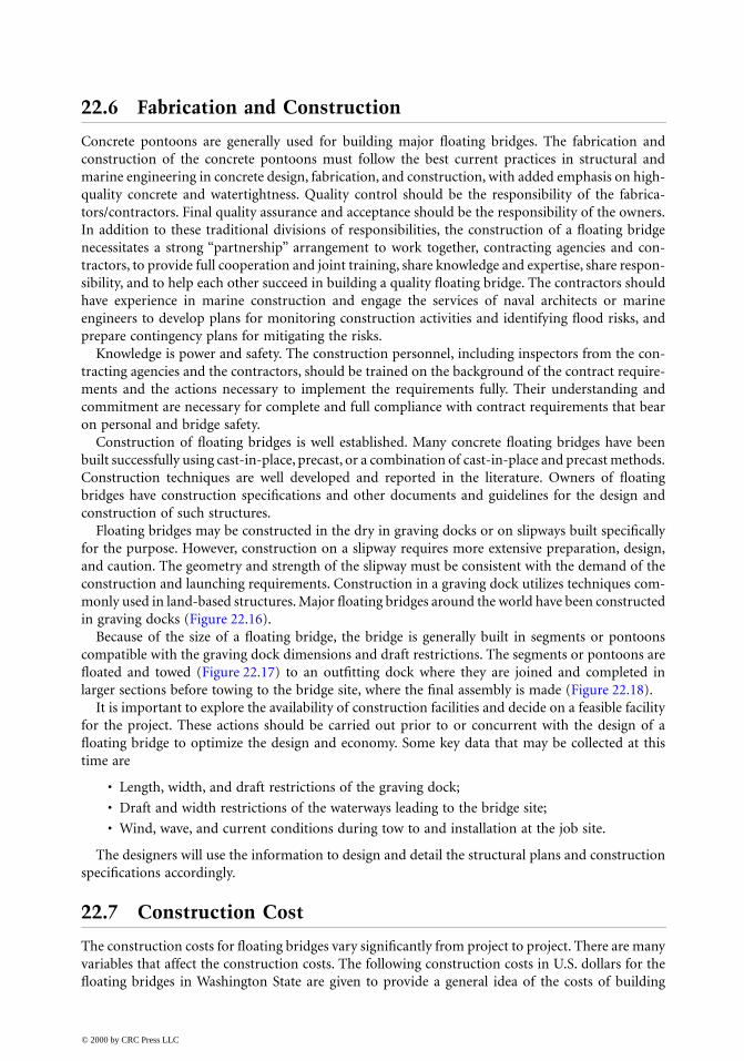
Floating bridges may be constructed in the dry in graving docks or on slipways built specificallyfor the purpose. However, construction on a slipway requires more extensive preparation, design,and caution. The geometry and strength of the slipway must be consistent with the demand of theconstruction and launching requirements. Construction in a graving dock utilizes techniques com-monly used in land-based structures. Major floating bridges around the world have been constructedin graving docks (Figure 22.16).
Because of the size of a floating bridge, the bridge is generally built in segments or pontoonscompatible with the graving dock dimensions and draft restrictions. The segments or pontoons arefloated and towed (Figure 22.17) to an outfitting dock where they are joined and completed inlarger sections before towing to the bridge site, where the final assembly is made (Figure 22.18).
It is important to explore the availability of construction facilities and decide on a feasible facilityfor the project. These actions should be carried out prior to or concurrent with the design of afloating bridge to optimize the design and economy. Some key data that may be collected at thistime are
• Length, width, and draft restrictions of the graving dock;
• Draft and width restrictions of the waterways leading to the bridge site;
• Wind, wave, and current conditions during tow to and installation at the job site.
The designers will use the information to design and detail the structural plans and constructionspecifications accordingly.
22.7 Construction Cost
The construction costs for floating bridges vary significantly from project to project. There are manyvariables that affect the construction costs. The following construction costs in U.S. dollars for thefloating bridges in Washington State are given to provide a general idea of the costs of building
© 2000 by CRC Press LLC
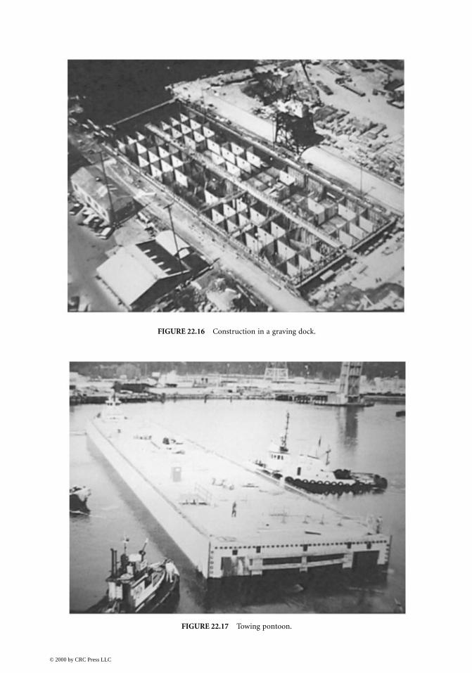
FIGURE 22.16 Construction in a graving dock.
FIGURE 22.17 Towing pontoon.
© 2000 by CRC Press LLC
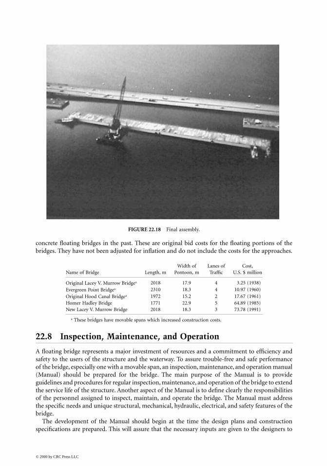
concrete floating bridges in the past. These are original bid costs for the floating portions of thebridges. They have not been adjusted for inflation and do not include the costs for the approaches.
22.8 Inspection, Maintenance, and Operation
A floating bridge represents a major investment of resources and a commitment to efficiency andsafety to the users of the structure and the waterway. To assure trouble-free and safe performanceof the bridge, especially one with a movable span, an inspection, maintenance, and operation manual(Manual) should be prepared for the bridge. The main purpose of the Manual is to provideguidelines and procedures for regular inspection, maintenance, and operation of the bridge to extendthe service life of the structure. Another aspect of the Manual is to define clearly the responsibilitiesof the personnel assigned to inspect, maintain, and operate the bridge. The Manual must addressthe specific needs and unique structural, mechanical, hydraulic, electrical, and safety features of thebridge.
The development of the Manual should begin at the time the design plans and constructionspecifications are prepared. This will assure that the necessary inputs are given to the designers to
FIGURE 22.18 Final assembly.
Width of Lanes of Cost, Name of Bridge Length, m Pontoon, m Traffic U.S. $ million
Original Lacey V. Murrow Bridgea 2018 17.9 4 3.25 (1938)
Evergreen Point Bridgea 2310 18.3 4 10.97 (1960)
Original Hood Canal Bridgea 1972 15.2 2 17.67 (1961)Homer Hadley Bridge 1771 22.9 5 64.89 (1985)New Lacey V. Murrow Bridge 2018 18.3 3 73.78 (1991)
a These bridges have movable spans which increased construction costs.
© 2000 by CRC Press LLC
help with preparation of the Manual later. The construction specifications should require thecontractors to submit documents, such as catalog cuts, schematics, electrical diagrams, etc., thatwill be included in the Manual. The Manual should be completed soon after the construction iscompleted and the bridge is placed into service. The Manual is a dynamic document. Lessons learnedand modifications made during the service life of the structure should be incorporated into theManual on a regular basis.
A training program should be developed for the supervisors and experienced co-workers toimpart knowledge to new or inexperienced workers. The training program should be given regularlyand aimed at nurturing a positive environment where workers help workers understand and dili-gently apply and update the guidelines and procedures of the Manual.
22.9 Closing Remarks
Floating bridges are cost-effective alternatives for crossing large lakes with unusual depth and softbottom, spanning across picturesque fjords, and connecting beautiful islands. For conditions likeLake Washington in Seattle where the lake is over 1610 m wide, 61 m deep, and another 61 m ofsoft bottom, a floating bridge is estimated to cost three to five times less than a long-span fixedbridge, tube, or tunnel.
The bridge engineering community has sound theoretical knowledge, technical expertise, andpractical skills to build floating bridges to enhance the social and economic activities of the people.However, it takes time to plan, study, design, and build floating bridges to form major transportationlinks in a local or national highway system. There are environmental, social, and economic issuesto address. In the State of Washington, the first floating bridge was conceived in 1920, but was notbuilt and opened to traffic until 1940. After over 30 years of planning, studies, and overcomingenvironmental, social, and economic issues, Norway finally has the country’s first two floatingbridges opened to traffic in 1992 and 1994. It is never too early to start the planning process andfeasibility studies once interest and a potential site for a floating bridge is identified.
Every floating bridge is unique and has its own set of technical, environmental, social, andeconomic issues to address during preliminary and final engineering:
• Winds and waves: Predicting accurately the characteristics of winds and waves has been adifficult part of floating bridge design. Generally there is inadequate data. It is advisable toinstall instruments in potential bridge sites to collect climatological data as early as possible.Research in the area of wind–wave–structure interactions will assure safe and cost-effectivestructures.
• Earthquake: Floating bridges are not directly affected by ground shakings from earthquakes.
• Tsunami and seiches: These may be of particular significant in building floating bridges atsites susceptible to these events. The dynamic response of floating bridges to tsunami andseiches must be studied and addressed in the design where deemed necessary.
• Corrosion: Materials and details must be carefully selected to reduce corrosion problems toassure long service life with low maintenance.
• Progressive failure: Floating bridges must be designed against progressive failures by dividingthe interiors of pontoons into small watertight compartments, by installing instruments fordetecting water entry, and by providing means to discharge the water when necessary.
• Riding comfort and convenience: Floating bridges must be comfortable to ride on during minorstorms. They must have adequate stiffness and stability. They must not be closed to vehiculartraffic frequently for storms or marine traffic.
• Public acceptance: Public acceptance is a key part of modern civil and structural engineering.The public must be educated regarding the environmental, social, and economic impacts of
© 2000 by CRC Press LLC
proposed projects. Reaching out to the public through community meetings, public hearings,news releases, tours, exhibits, etc. during the early phase of project development is importantto gain support and assure success. Many major public projects have been delayed for yearsand years because of lack of interaction and understanding.
• Design criteria: The design criteria must be carefully developed to meet site-specific require-ments and focused on design excellence and cost-effectiveness to provide long-term perfor-mance and durability. Design excellence and economy come from timely planning, properselection of materials for durability and strength, and paying attention to design details,constructibility, and maintainability. The design team should include professionals withknowledge and experience in engineering, inspection, fabrication, construction, mainte-nance, and operation of floating bridges or marine structures.
• Construction plan: It is essential to have a good set of construction plans developed jointlyby the contracting agency and the contractor to clearly address qualifications, materialscontrol, quality control, quality assurance, acceptance criteria, post-tensioning techniques,repair techniques, launching and towing requirements, weather conditions, flood control andsurveillance.
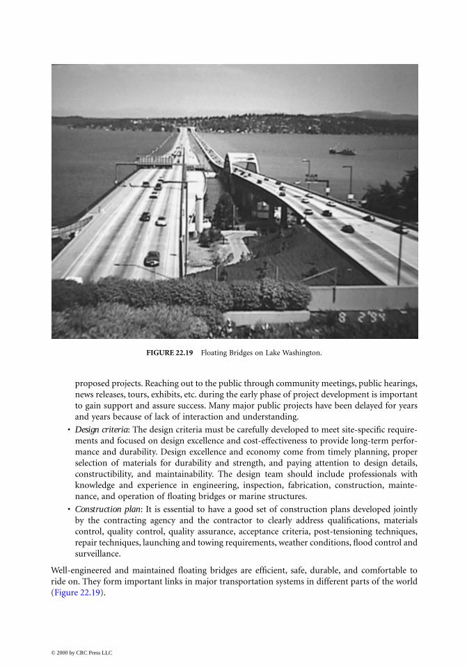
Well-engineered and maintained floating bridges are efficient, safe, durable, and comfortable toride on. They form important links in major transportation systems in different parts of the world(Figure 22.19).
FIGURE 22.19 Floating Bridges on Lake Washington.
© 2000 by CRC Press LLC

References
1. Andrew, C. E., The Lake Washington pontoon bridge, Civil Eng., 9(12), 1939.2. Lwin, M. M., Floating bridges — solution to a difficult terrain, in Proceedings of the Conference on
Transportation Facilities through Difficult Terrain, Wu, J. T. H. and Barrett, R. K., Eds., A.A. Balkema,Rotterdam, 1993.
3. Nichols, C. C., Construction and performance of hood canal floating bridge, in Proceedings ofSymposium on Concrete Construction in Aqueous Environment, ACI Publication SP-8, Detroit, MI,1962.
4. Pegusch, W., The Kelowna floating bridge, in The Engineering Journey, the Engineering Instituteof Canada, Canada, 1957.
5. Landet, E., Planning and construction of floating bridges in Norway, Proceedings of InternationalWorkshop on Floating Structures in Coastal Zone, Port and Harbour Research Institute, Japan, 1994.
6. Gloyd, C. S., Concrete floating bridges, Concrete Int., 10(7), 1988.7. AASHTO, Standard Specifications for Highway Bridges, 16th ed., AASHTO, Washington, D.C., 1996.8. AASHTO, LRFD Bridge Design Specifications, AASHTO, Washington, D.C., 1994.9. Lwin, M. M., Bruesch, A. W., and Evans, C. F., High performance concrete for a floating bridge,
in Proceedings of the Fourth International Bridge Engineering Conference, Vol. 1, Federal HighwayAdministration, Washington, D.C., 1995.
10. Lwin, M. M., Use of high performance concrete in highway bridges in Washington State, in Pro-ceedings International Symposium on High Performance Concrete, Prestressed Concrete Institute andFederal Highway Administration, New Orleans, 1997.
11. AASHTO, Standard Specifications for Movable Highway Bridges, AASHTO, Washington, D.C., 1988.12. Bachman, H. and Amman, W., Vibrations in Structure Induced by Men and Machines, Structural
Engineering Document No. 3e, International Association for Bridge and Structural Engineering,Zurich, Switzerland, 1987.
13. Hetenyi, M., Beams on Elastic Foundation, Ann Arbor, MI, 1979.14. Frank, W., Oscillation of cylinders in or below the surface of deep fluids, Report No. 2375, Naval
Ships Research and Development Center, 1967.15. Garrison, C. J., Interaction of oblique waves with an infinite cylinder, Appl. Ocean Res., 6(1), 1984.16. Shore Protection Manual, Vol. 1, Coastal Engineering Research Center, Department of the Army, 1984.17. Program NARFET, Waterways Experiment Station, Corps of Engineers, Coastal Engineering
Research Center, Vicksburg, MI.18. Mitsuyasu, H., Observations of the directional spectrum of ocean waves using a clover leaf buoy,
J. Phys. Oceanogr., Vol. 5, 1975.19. Comstock, J., Principles of Naval Architecture, Society of Naval Architects and Marine Engineers,
New York, 1975.20. Salvesen, N., Tuck, E. O., and Faltinsen, O., Ship motions and sea loads, Trans. Soc. Naval Architects
Marine Eng., 78, 1970.21. Engel, D. J. and Nachlinger, R. R., Frequency domain analysis of dynamic response of floating
bridge to waves, in Proceedings of Ocean Structural Dynamics Symposium, Oregon State University,1982.
22. Hutchison, B. L., Impulse response techniques for floating bridges and breakwaters subject to short-crested seas, Marine Technol., 21(3), 1984.
23. Marks, W., The Application of Spectral Analysis and Statistics to Seakeeping, T&R Bulletin No. 1-24,Society of Naval Architects and Marine Engineers, New York, 1963.
24. Ochi, M. K., On prediction of extreme values, J. Ship Res., 17(1), 1973.25. Gray, D. L. and Hutchison, B. L., A resolution study for computer modeling of floating bridges, in
Proceedings of Ocean Structural Dynamics Symposium, Oregon State University, 1986.
© 2000 by CRC Press LLC