Embed Size (px)
Citation preview

Dornsife, R.J. "Expansion Joints." Bridge Engineering Handbook. Ed. Wai-Fah Chen and Lian Duan Boca Raton: CRC Press, 2000
25Expansion Joints
25.1 Introduction
25.2 General Design Criteria
25.3 Jointless Bridges
25.4 Small Movement Range JointsSliding Plate Joints • Compression Seal Joints • Asphaltic Plug Joints • Poured Sealant Joints • Design Example 1
25.5 Medium Movement Range JointsBolt-Down Panel Joints • Strip Seal Joints • Steel Finger Joints • Design Example 2
25.6 Large Movement Range JointsModular Bridge Expansion Joints • Design Example 3
25.7 Construction and Maintenance
25.1 Introduction
Expansion joint systems are integral, yet often overlooked, components designed to accommodatecyclic movements. Properly functioning bridge expansion joint systems accommodate these move-ments without imposing significant secondary stresses on the superstructure. Sealed expansion jointsystems provide barriers preventing runoff water and deicing chemicals from passing through thejoint onto bearing and substructure elements below the bridge deck. Water and deicing chemicalshave a detrimental impact on overall structural performance by accelerating degradation of bridgedeck, bearing, and substructure elements. In extreme cases, this degradation has resulted in pre-mature, catastrophic structural failure. In fulfilling their functions, expansion joints must providea reasonably smooth ride for motorists.
Perhaps because expansion joints are generally designed and installed last, they are often relegatedto peripheral status by designers, builders, and inspectors. As a result of their geometric configurationand the presence of multiple-axle vehicles, expansion joint elements are generally subjected to a signif-icantly larger number of loadings than other structural members. Impact, a consequence of bridgediscontinuity inherent at a joint, exacerbates loading. Unfortunately, specific expansion joint systemsare often selected based upon their initial cost with minimal consideration for long-term performance,durability, and maintainability. Consequently, a plethora of bridge maintenance problems plague them.
In striving to improve existing and develop new expansion joint systems, manufacturers presentengineers with a multitudinous array of options. In selecting a particular system, the designer mustcarefully assess specific requirements. Magnitude and direction of movement, type of structure,traffic volumes, climatic conditions, skew angles, initial and life cycle costs, and past performanceof alternative systems must all be considered. For classification in the ensuing discussion, expansionjoint systems will be grouped into three broad categories depending upon the total movement range
Ralph J. DornsifeWashington State Department
of Transportation
© 2000 by CRC Press LLC
accommodated. Small movement range joints encompass all systems capable of accommodatingtotal motion ranges of up to about 45 mm. Medium movement range joints include systemsaccommodating total motion ranges between about 45 mm and about 130 mm. Large movementrange joints accommodate total motion ranges in excess of about 130 mm. These delineated rangesare somewhat arbitrary in that some systems can accommodate movement ranges overlapping thesebroad categories.
25.2 General Design Criteria
Expansion joints must accommodate movements produced by concrete shrinkage and creep, post-tensioning shortening, thermal variations, dead and live loads, wind and seismic loads, and structuresettlements. Concrete shrinkage, post-tensioning shortening, and thermal variations are generallytaken into account explicitly in design calculations. Because of uncertainties in predicting, and theincreased costs associated with accommodating large displacements, seismic movements are usuallynot explicitly included in calculations.
Expansion joints should be designed to accommodate all shrinkage occurring after their instal-lation. For unrestrained concrete, ultimate shrinkage strain after installation, β, may be estimatedas 0.0002 [1]. More-detailed estimations can be used which include the effect of ambient relativehumidity and volume-to-surface ratios [2]. Shrinkage shortening of the bridge deck, ∆shrink, in mm,is calculated as
∆shrink = (β) · (µ) · (Ltrib) · (1000 mm/m) (25.1)
whereLtrib =tributary length of structure subject to shrinkage; mβ = ultimate shrinkage strain after expansion joint installation; estimated as 0.0002 in lieu of
more-refined calculationsµ = factor accounting for restraining effect imposed by structural elements installed before slab
is cast [1]= 0.0 for steel girders, 0.5 for precast prestressed concrete girders, 0.8 for concrete box girders
and T-beams, 1.0 for flat slabs
Thermal displacements are calculated using the maximum and minimum anticipated bridge decktemperatures. These extreme values are functions of the geographic location of the structure andthe bridge type. Thermal movement, in mm, is calculated as
∆temp = (α) · (Ltrib) · (δT) · (1000 mm/m) (25.2)
whereα = coefficient of thermal expansion; 0.000011 m/m/°C for concrete and 0.000012 m/m/°C for
steelLtrib = tributary length of structure subject to thermal variation; mδT = temperature variation; °C
Any other predictable movements following expansion joint installation, such as concrete post-tensioning shortening and creep, should also be included in the design calculations.
25.3 Jointless Bridges
Bridge designers have used superstructure continuity in an effort to avoid some of the maintenanceproblems associated with expansion joints [3]. This evolution from simple-span construction was facil-itated by the development of the moment distribution procedure published by Hardy Cross [4] in 1930.
© 2000 by CRC Press LLC
In recent years, some transportation agencies have extended this strategy by developing jointlessbridge designs. Jointless bridges are characterized by continuous spans built integrally with theirabutments. In many instances, approach slabs are tied to the superstructure slab or to the abutments.The resulting designs are termed integral or semi-integral depending upon the degree of continuitydeveloped among superstructure, substructure, and approach slab elements. Design methods anddetails for jointless bridges vary considerably [3,5]. Many transportation agencies have empiricallyestablished maximum lengths for jointless bridges [5].
Jointless bridges should not be considered a panacea for addressing expansion jointmaintenanceproblems. As superstructure movements are restrained in jointless bridges, secondary stresses areinduced in superstructure and substructure elements. Stresses may also be induced in approachslabs. If inadequately addressed during design, these stresses can damage structural elements andadjacent asphalt pavements. Damaged structural elements, slabs, and pavements are accompaniedby increased probability of moisture infiltration, further exacerbating deterioration. Most jointlessbridges have been built relatively recently [5]. Their long-term performance and durability willdetermine how extensively the jointless bridge concept is applied to future construction.
25.4 Small Movement Range Joints
Many different systems exist for accommodating movement ranges under about 45 mm. Theseinclude, but are not limited to, steel sliding plates, elastomeric compression seals, preformed closedcell foam, epoxy-bonded elastomeric glands, asphaltic plug joints, bolt-down elastomeric panels,and poured sealants. In this section, several of these systems will be discussed with an emphasis ondesign procedures and past performance.
25.4.1 Sliding Plate Joints
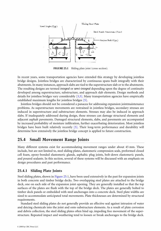
Steel sliding plates, shown in Figure 25.1, have been used extensively in the past for expansion jointsin both concrete and timber bridge decks. Two overlapping steel plates are attached to the bridgedeck, one on each side of the expansion joint opening. They are generally installed so that the topsurfaces of the plates are flush with the top of the bridge deck. The plates are generally bolted totimber deck panels or embedded with steel anchorages into a concrete deck. Steel plate widths aresized to accommodate anticipated total movements. Plate thicknesses are determined by structuralrequirements.
Standard steel sliding plates do not generally provide an effective seal against intrusion of waterand deicing chemicals into the joint and onto substructure elements. As a result of plate corrosionand debris collection, the steel sliding plates often bind up, impeding free movement of the super-structure. Repeated impact and weathering tend to loosen or break anchorages to the bridge deck.
FIGURE 25.1 Sliding plate joint (cross section).
© 2000 by CRC Press LLC
Consequently, sliding plate systems are rarely specified for new bridge construction today. Never-theless, sliding plate systems still exist on many older structures. These systems can be replaced withnewer systems providing increased resistance against water and debris infiltration. In situationswhere the integrity of the deck anchorage has not been compromised, sliding plates can be retrofittedwith poured sealants or elastomeric strip seals.
25.4.2 Compression Seal Joints
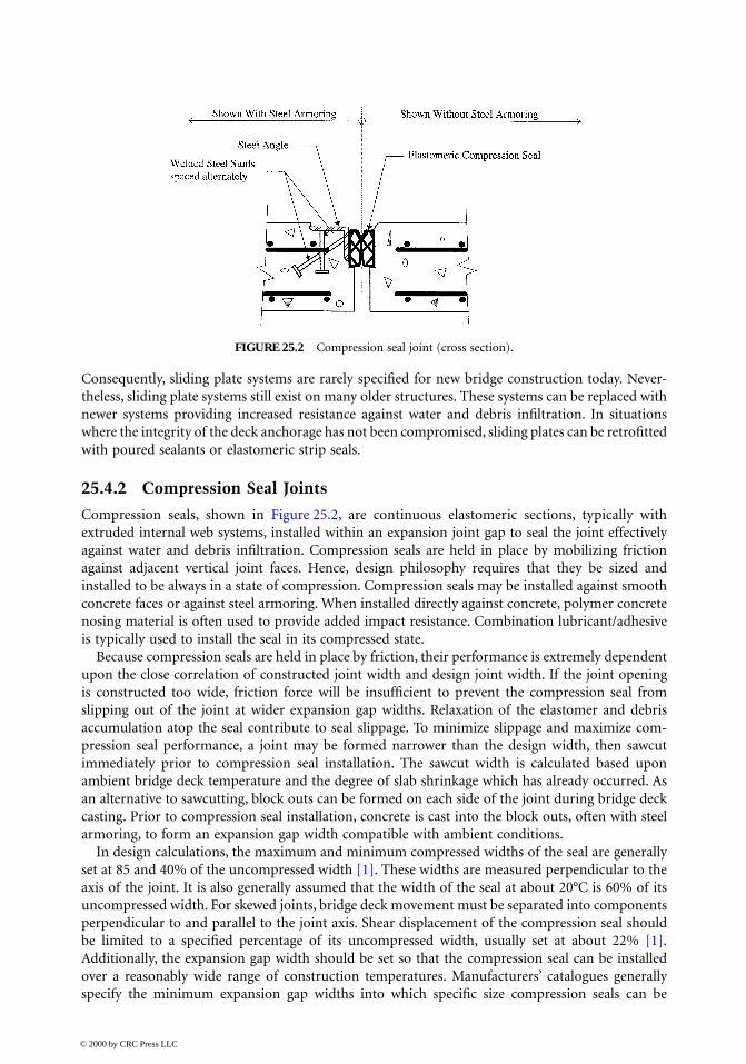
Compression seals, shown in Figure 25.2, are continuous elastomeric sections, typically withextruded internal web systems, installed within an expansion joint gap to seal the joint effectivelyagainst water and debris infiltration. Compression seals are held in place by mobilizing frictionagainst adjacent vertical joint faces. Hence, design philosophy requires that they be sized andinstalled to be always in a state of compression. Compression seals may be installed against smoothconcrete faces or against steel armoring. When installed directly against concrete, polymer concretenosing material is often used to provide added impact resistance. Combination lubricant/adhesiveis typically used to install the seal in its compressed state.
Because compression seals are held in place by friction, their performance is extremely dependentupon the close correlation of constructed joint width and design joint width. If the joint openingis constructed too wide, friction force will be insufficient to prevent the compression seal fromslipping out of the joint at wider expansion gap widths. Relaxation of the elastomer and debrisaccumulation atop the seal contribute to seal slippage. To minimize slippage and maximize com-pression seal performance, a joint may be formed narrower than the design width, then sawcutimmediately prior to compression seal installation. The sawcut width is calculated based uponambient bridge deck temperature and the degree of slab shrinkage which has already occurred. Asan alternative to sawcutting, block outs can be formed on each side of the joint during bridge deckcasting. Prior to compression seal installation, concrete is cast into the block outs, often with steelarmoring, to form an expansion gap width compatible with ambient conditions.
In design calculations, the maximum and minimum compressed widths of the seal are generallyset at 85 and 40% of the uncompressed width [1]. These widths are measured perpendicular to theaxis of the joint. It is also generally assumed that the width of the seal at about 20°C is 60% of itsuncompressed width. For skewed joints, bridge deck movement must be separated into componentsperpendicular to and parallel to the joint axis. Shear displacement of the compression seal shouldbe limited to a specified percentage of its uncompressed width, usually set at about 22% [1].Additionally, the expansion gap width should be set so that the compression seal can be installedover a reasonably wide range of construction temperatures. Manufacturers’ catalogues generallyspecify the minimum expansion gap widths into which specific size compression seals can be
FIGURE 25.2 Compression seal joint (cross section).
© 2000 by CRC Press LLC

installed. The expansion gap width should be specified on the contract drawings as a function ofthe bridge deck temperature.
Design relationships can be stated as follows:
∆temp-normal = ∆temp · cos θ [thermal movement normal to joint] (25.3)
∆temp-parallel = ∆temp · sin θ [thermal movement parallel to joint] (25.4)
∆shrink-normal = ∆shrink · cos θ [shrinkage movement normal to joint] (25.5)
∆shrink-parallel = ∆shrink · sin θ [shrinkage movement parallel to joint] (25.6)
Wmin = Winstall – [(Tmax – Tinstall)/(Tmax – Tmin)] ∆temp-normal > 0.40W (25.7)
Wmax = Winstall + [(Tinstall – Tmin)/(Tmax – Tmin)] ∆temp-normal + ∆shrink-normal < 0.85W (25.8)
whereθ = skew angle of expansion joint, measured with respect to a line perpendicular to the
bridge longitudinal axis; degreesW = uncompressed width of compression seal; mmWinstall = expansion gap width at installationTinstall = bridge deck temperature at time of installation; °CWmin, Wmax = minimum and maximum expansion gap widths; mmTmin, Tmax = minimum and maximum bridge deck temperatures; °C
Multiplying Eq. (25.7) by –1.0, adding to Eq. (25.8), and rearranging yields:
W > (∆temp-normal + ∆shrink-normal)/0.45 (25.9)
Similarly,
W > (∆temp-parallel + ∆shrink-parallel)/0.22 (25.10)
Now, assuming Winstall = 0.6 W,
Wmax = 0.6W + [(Tinstall – Tmin)/(Tmax – Tmin)] ∆temp-normal + ∆shrink-normal < 0.85W (25.11)
which, upon rearranging, yields:
W > 4 [(Tinstall – Tmin)/(Tmax – Tmin) ·(∆temp-normal) + ∆shrink-normal] (25.12)
Equations (25.9), (25.10), and (25.12) are used to calculate the required compression seal size. Next,expansion gap widths at various construction temperatures can be evaluated.
25.4.3 Asphaltic Plug Joints
Asphaltic plug joints comprise liquid polymer binder and graded aggregates compacted in pre-formed block outs as shown in Figure 25.3. The compacted composite material is referred to aspolymer modified asphalt (PMA). These joints have been used to accommodate movement rangesup to 50 mm. This expansion joint system was developed in Europe and can be adapted for usewith concrete or asphalt bridge deck surfaces. The PMA is installed continuously within a blockout centered over the expansion joint opening with the top of the PMA flush with the roadwaysurface. A steel plate retains the PMA at the bottom of the block out during installation. The polymer
© 2000 by CRC Press LLC
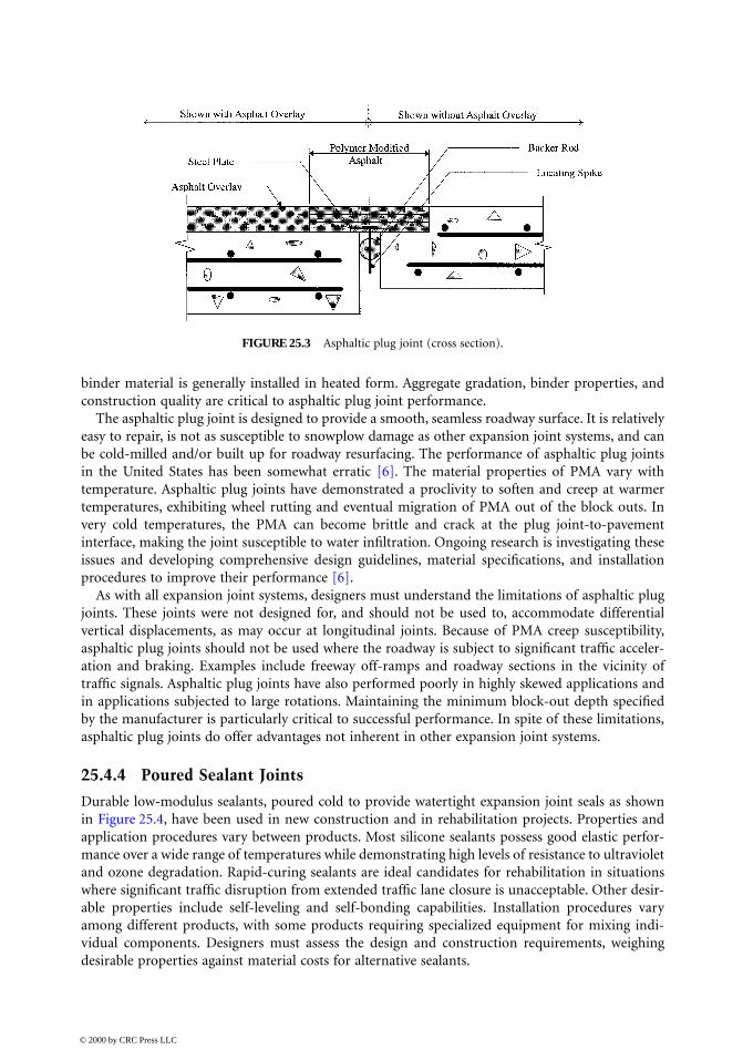
binder material is generally installed in heated form. Aggregate gradation, binder properties, andconstruction quality are critical to asphaltic plug joint performance.
The asphaltic plug joint is designed to provide a smooth, seamless roadway surface. It is relativelyeasy to repair, is not as susceptible to snowplow damage as other expansion joint systems, and canbe cold-milled and/or built up for roadway resurfacing. The performance of asphaltic plug jointsin the United States has been somewhat erratic [6]. The material properties of PMA vary withtemperature. Asphaltic plug joints have demonstrated a proclivity to soften and creep at warmertemperatures, exhibiting wheel rutting and eventual migration of PMA out of the block outs. Invery cold temperatures, the PMA can become brittle and crack at the plug joint-to-pavementinterface, making the joint susceptible to water infiltration. Ongoing research is investigating theseissues and developing comprehensive design guidelines, material specifications, and installationprocedures to improve their performance [6].
As with all expansion joint systems, designers must understand the limitations of asphaltic plugjoints. These joints were not designed for, and should not be used to, accommodate differentialvertical displacements, as may occur at longitudinal joints. Because of PMA creep susceptibility,asphaltic plug joints should not be used where the roadway is subject to significant traffic acceler-ation and braking. Examples include freeway off-ramps and roadway sections in the vicinity oftraffic signals. Asphaltic plug joints have also performed poorly in highly skewed applications andin applications subjected to large rotations. Maintaining the minimum block-out depth specifiedby the manufacturer is particularly critical to successful performance. In spite of these limitations,asphaltic plug joints do offer advantages not inherent in other expansion joint systems.
25.4.4 Poured Sealant Joints
Durable low-modulus sealants, poured cold to provide watertight expansion joint seals as shownin Figure 25.4, have been used in new construction and in rehabilitation projects. Properties andapplication procedures vary between products. Most silicone sealants possess good elastic perfor-mance over a wide range of temperatures while demonstrating high levels of resistance to ultravioletand ozone degradation. Rapid-curing sealants are ideal candidates for rehabilitation in situationswhere significant traffic disruption from extended traffic lane closure is unacceptable. Other desir-able properties include self-leveling and self-bonding capabilities. Installation procedures varyamong different products, with some products requiring specialized equipment for mixing indi-vidual components. Designers must assess the design and construction requirements, weighingdesirable properties against material costs for alternative sealants.
FIGURE 25.3 Asphaltic plug joint (cross section).
© 2000 by CRC Press LLC
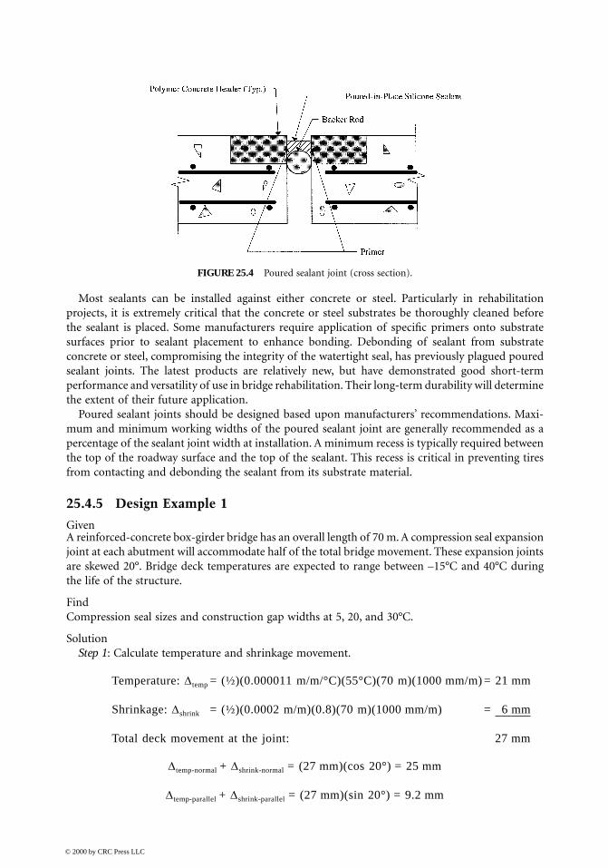
Most sealants can be installed against either concrete or steel. Particularly in rehabilitationprojects, it is extremely critical that the concrete or steel substrates be thoroughly cleaned beforethe sealant is placed. Some manufacturers require application of specific primers onto substratesurfaces prior to sealant placement to enhance bonding. Debonding of sealant from substrateconcrete or steel, compromising the integrity of the watertight seal, has previously plagued pouredsealant joints. The latest products are relatively new, but have demonstrated good short-termperformance and versatility of use in bridge rehabilitation. Their long-term durability will determinethe extent of their future application.
Poured sealant joints should be designed based upon manufacturers’ recommendations. Maxi-mum and minimum working widths of the poured sealant joint are generally recommended as apercentage of the sealant joint width at installation. A minimum recess is typically required betweenthe top of the roadway surface and the top of the sealant. This recess is critical in preventing tiresfrom contacting and debonding the sealant from its substrate material.
25.4.5 Design Example 1
GivenA reinforced-concrete box-girder bridge has an overall length of 70 m. A compression seal expansionjoint at each abutment will accommodate half of the total bridge movement. These expansion jointsare skewed 20°. Bridge deck temperatures are expected to range between –15°C and 40°C duringthe life of the structure.
FindCompression seal sizes and construction gap widths at 5, 20, and 30°C.
SolutionStep 1: Calculate temperature and shrinkage movement.
Temperature: ∆temp = (½)(0.000011 m/m/°C)(55°C)(70 m)(1000 mm/m) = 21 mm
Shrinkage: ∆shrink = (½)(0.0002 m/m)(0.8)(70 m)(1000 mm/m) = 6 mm
Total deck movement at the joint: 27 mm
∆temp-normal + ∆shrink-normal = (27 mm)(cos 20°) = 25 mm
∆temp-parallel + ∆shrink-parallel = (27 mm)(sin 20°) = 9.2 mm
FIGURE 25.4 Poured sealant joint (cross section).
© 2000 by CRC Press LLC
Step 2: Determine compression seal width required from Eqs. (25.9), (25.10), and (25.12).
W > 25 mm/0.45 = 56 mm
W > 9.2 mm/0.22 = 42 mm
W > 4 · [(20°C + 15°C)/(40°C + 15°C) · (21 mm) + 6 mm] · cos 20° = 73 mm
Use 75 mm compression seal.
Step 3: Evaluate construction gap widths for various temperatures for a 75 mm compression seal.
Construction width at 20°C= 0.6 · (75 mm) = 45 mm
Construction width at 5°C = 45 mm + [(20°C – 5°C)/(40°C + 15°C)] · (21 mm)· (cos 20°) = 50 mm
Construction width at 30°C= 45 mm – [(30°C – 20°C)/(40°C + 15°C)] · (21 mm)· (cos 20°) = 41 mm
ConclusionUse a 75-mm compression seal. Construction gap widths for installation temperatures of 5, 20, and30°C are 50, 45, and 41 mm, respectively.
25.5 Medium Movement Range Joints
Medium movement range expansion joints accommodate movement ranges from about 45 mm toabout 130 mm and include sliding plate systems, bolt-down panel joints (elastomeric expansiondams), strip seals, and steel finger joints. Sliding plate systems were previously discussed undersmall motion range joints.
25.5.1 Bolt-Down Panel Joints
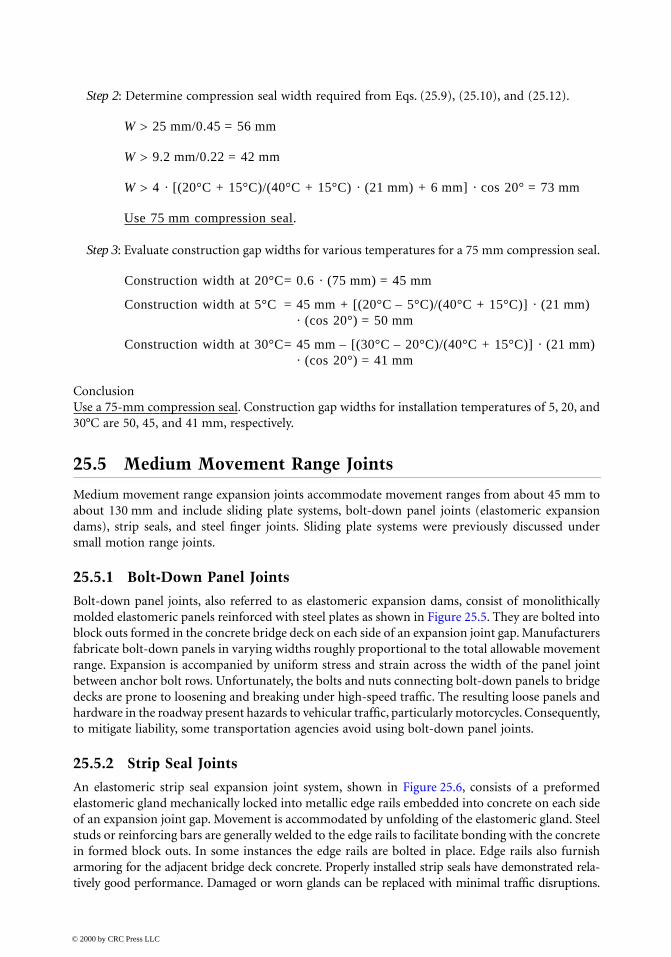
Bolt-down panel joints, also referred to as elastomeric expansion dams, consist of monolithicallymolded elastomeric panels reinforced with steel plates as shown in Figure 25.5. They are bolted intoblock outs formed in the concrete bridge deck on each side of an expansion joint gap. Manufacturersfabricate bolt-down panels in varying widths roughly proportional to the total allowable movementrange. Expansion is accompanied by uniform stress and strain across the width of the panel jointbetween anchor bolt rows. Unfortunately, the bolts and nuts connecting bolt-down panels to bridgedecks are prone to loosening and breaking under high-speed traffic. The resulting loose panels andhardware in the roadway present hazards to vehicular traffic, particularly motorcycles. Consequently,to mitigate liability, some transportation agencies avoid using bolt-down panel joints.
25.5.2 Strip Seal Joints
An elastomeric strip seal expansion joint system, shown in Figure 25.6, consists of a preformedelastomeric gland mechanically locked into metallic edge rails embedded into concrete on each sideof an expansion joint gap. Movement is accommodated by unfolding of the elastomeric gland. Steelstuds or reinforcing bars are generally welded to the edge rails to facilitate bonding with the concretein formed block outs. In some instances the edge rails are bolted in place. Edge rails also furnisharmoring for the adjacent bridge deck concrete. Properly installed strip seals have demonstrated rela-tively good performance. Damaged or worn glands can be replaced with minimal traffic disruptions.
© 2000 by CRC Press LLC
The elastomeric glands exhibit a proclivity for accumulating debris. In some instances, this debriscan resist joint movement and result in premature gland failure.
25.5.3 Steel Finger Joints
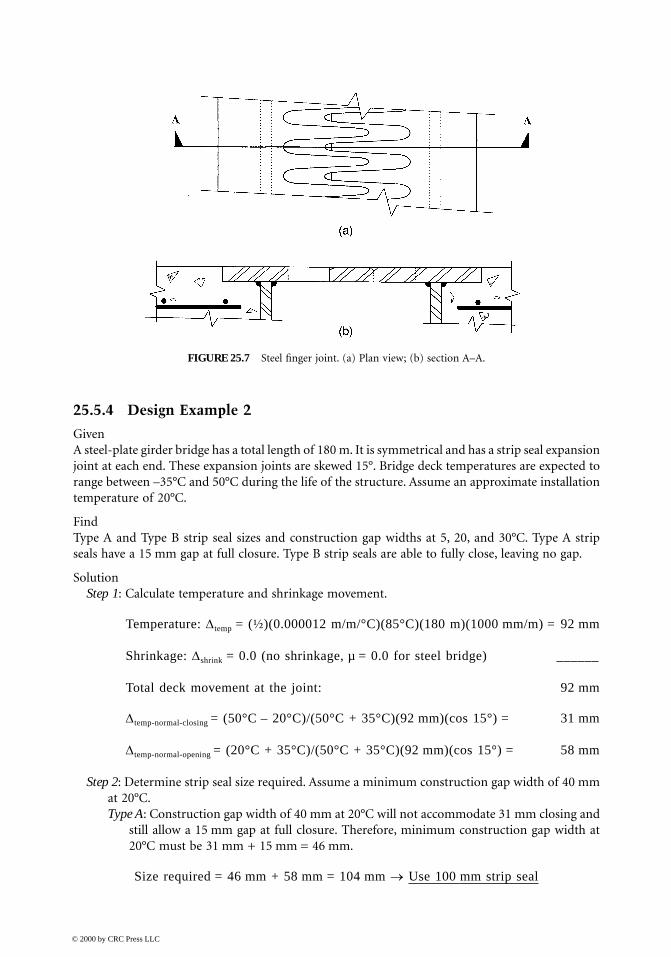
Steel finger joints, shown in Figure 25.7, have been used to accommodate medium and largemovement ranges. These joints are generally fabricated from steel plate and are installed in cantileveror prop cantilever configurations. The steel fingers must be designed to support traffic loads withsufficient stiffness to preclude excessive vibration. In addition to longitudinal movement, they mustalso accommodate any rotation or differential vertical deflection across the joint. To minimize thepotential for damage from snowplow blade impact, steel fingers may be fabricated with a slightdownward taper toward the joint centerline. Generally, steel finger joints do not provide a sealagainst water intrusion to substructure elements. Elastomeric or metallic troughs can be installedbeneath the steel finger joint assembly to catch and redirect water and debris runoff. However,unless regularly maintained, these troughs clog and become ineffective [3].
FIGURE 25.5 Bolt-down panel joint (cross section).
FIGURE 25.6 Elastomeric strip seal joint (cross section).
© 2000 by CRC Press LLC
25.5.4 Design Example 2
GivenA steel-plate girder bridge has a total length of 180 m. It is symmetrical and has a strip seal expansionjoint at each end. These expansion joints are skewed 15°. Bridge deck temperatures are expected torange between –35°C and 50°C during the life of the structure. Assume an approximate installationtemperature of 20°C.
FindType A and Type B strip seal sizes and construction gap widths at 5, 20, and 30°C. Type A stripseals have a 15 mm gap at full closure. Type B strip seals are able to fully close, leaving no gap.
SolutionStep 1: Calculate temperature and shrinkage movement.
Temperature: ∆temp = (½)(0.000012 m/m/°C)(85°C)(180 m)(1000 mm/m) = 92 mm
Shrinkage: ∆shrink = 0.0 (no shrinkage, µ = 0.0 for steel bridge) ______
Total deck movement at the joint: 92 mm
∆temp-normal-closing = (50°C – 20°C)/(50°C + 35°C)(92 mm)(cos 15°) = 31 mm
∆temp-normal-opening = (20°C + 35°C)/(50°C + 35°C)(92 mm)(cos 15°) = 58 mm
Step 2: Determine strip seal size required. Assume a minimum construction gap width of 40 mmat 20°C.Type A: Construction gap width of 40 mm at 20°C will not accommodate 31 mm closing and
still allow a 15 mm gap at full closure. Therefore, minimum construction gap width at20°C must be 31 mm + 15 mm = 46 mm.
Size required = 46 mm + 58 mm = 104 mm → Use 100 mm strip seal
FIGURE 25.7 Steel finger joint. (a) Plan view; (b) section A–A.
© 2000 by CRC Press LLC
Type B: Construction width of 40 mm at 20°C is adequate.
Size required = 40 mm + 58 mm = 98 mm → Use 100 mm strip seal
Step 3: Evaluate construction gap widths for various temperatures for a 100 mm strip seal.Type A: Required construction gap width at 20°C = 15 mm + 31 mm = 46 mm
Construction gap width at 5°C = 46 mm + (20°C – 5°C)/(20°C + 35°C)(58 mm)= 62 mm
Construction gap width at 30°C = 46 mm – (30°C – 20°C)/(50°C – 20°C)(31 mm)= 36 mm
Type B: Construction width of 40 mm at 20°C is adequate.
Construction gap width at 5°F = 40 mm + (20°C – 5°C)/(20°C + 35°C)(58 mm)= 56 mm
Construction gap width at 30°F = 40 mm – (30°C – 20°C)/(50°C – 20°C)(31 mm)= 30 mm
ConclusionUse a 100 mm strip seal. Construction gap widths for Type A strip seals at installation temperaturesof 5, 20, and 30°C are 62, 46, and 36 mm, respectively. Construction gap widths for Type B stripseals at installation temperatures of 5, 20, and 30°C are 56, 40, and 30 mm, respectively.
25.6 Large Movement Range Joints
Large movement range joints accommodate more than 130 mm of total movement and includebolt-down panel joints (elastomeric expansion dams), steel finger joints, and modular expansionjoints. Bolt-down panel and steel finger joints were previously discussed as medium movementrange joints.
25.6.1 Modular Bridge Expansion Joints
Modular bridge expansion joints (MBEJ), shown in Figure 25.8, are complex, expensive, structuralsystems designed to provide watertight wheel load transfer across wide expansion joint openings.These systems were developed in Europe and introduced in the United States in the 1960s [7]. Theyare generally shipped to the construction site for installation in a completely assembled configura-tion. MBEJs comprise a series of center beams supported atop support bars. The center beams areoriented parallel to the joint axis while the support bars span parallel to the primary direction ofmovement. MBEJs can be classified as either single-support bar systems or multiple-support barsystems. In multiple-support bar systems, each center beam is supported by a separate support barat each support location. Figure 25.8 depicts a multiple-support bar system. In the more complexsingle-support bar system, one support bar supports all center beams at each support location. Thisdesign concept requires that each center beam be free to translate along the longitudinal axis of thesupport bar as the joint opens and closes. This is accomplished by attaching steel yokes to theunderside of the center beams. The support bar passes through the openings in the yokes. Elasto-meric springs between the underside of each center beam and the top of the support bar and betweenthe bottom of the support bar and the bottom of the yoke support each center beam and permitit to translate along the longitudinal axis of the support bar.
© 2000 by CRC Press LLC
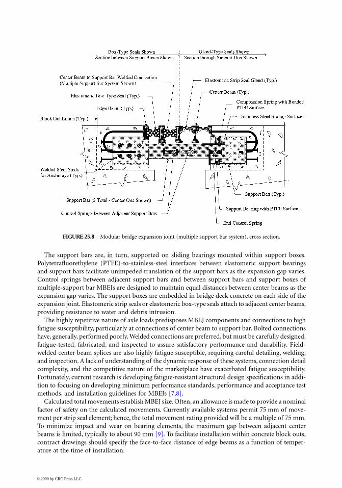
The support bars are, in turn, supported on sliding bearings mounted within support boxes.Polytetrafluorethylene (PTFE)-to-stainless-steel interfaces between elastomeric support bearingsand support bars facilitate unimpeded translation of the support bars as the expansion gap varies.Control springs between adjacent support bars and between support bars and support boxes ofmultiple-support bar MBEJs are designed to maintain equal distances between center beams as theexpansion gap varies. The support boxes are embedded in bridge deck concrete on each side of theexpansion joint. Elastomeric strip seals or elastomeric box-type seals attach to adjacent center beams,providing resistance to water and debris intrusion.
The highly repetitive nature of axle loads predisposes MBEJ components and connections to highfatigue susceptibility, particularly at connections of center beam to support bar. Bolted connectionshave, generally, performed poorly. Welded connections are preferred, but must be carefully designed,fatigue-tested, fabricated, and inspected to assure satisfactory performance and durability. Field-welded center beam splices are also highly fatigue susceptible, requiring careful detailing, welding,and inspection. A lack of understanding of the dynamic response of these systems, connection detailcomplexity, and the competitive nature of the marketplace have exacerbated fatigue susceptibility.Fortunately, current research is developing fatigue-resistant structural design specifications in addi-tion to focusing on developing minimum performance standards, performance and acceptance testmethods, and installation guidelines for MBEJs [7,8].
Calculated total movements establish MBEJ size. Often, an allowance is made to provide a nominalfactor of safety on the calculated movements. Currently available systems permit 75 mm of move-ment per strip seal element; hence, the total movement rating provided will be a multiple of 75 mm.To minimize impact and wear on bearing elements, the maximum gap between adjacent centerbeams is limited, typically to about 90 mm [9]. To facilitate installation within concrete block outs,contract drawings should specify the face-to-face distance of edge beams as a function of temper-ature at the time of installation.
FIGURE 25.8 Modular bridge expansion joint (multiple support bar system), cross section.
© 2000 by CRC Press LLC

Design relationships can be expressed as:
n = MR/mr (25.13)
Gmin = (n – 1) · (w) + (n) · (g) (25.14)
Gmax = Gmin + MR (25.15)
whereMR = total movement rating of the MBEJ system; mmmr = movement rating per strip seal element; mmn = number of sealsn – 1 = number of center beamsw = width of each center beam; mmg = minimum gap per strip seal element at full closure; mmGmin = minimum face-to-face distance of edge beams; mmGmax = maximum face-to-face distance of edge beams; mm
Structural design of MBEJs is generally performed by the manufacturer. Project specificationsshould require that the manufacturer submit structural calculations, detailed fabrication drawings,and applicable fatigue tests for approval. All elements and connections must be designed and detailedto resist fatigue stresses imposed by repetitive vertical and horizontal wheel loadings. Additionally,MBEJs should be detailed to provide access for inspection and periodic maintenance, includingreplacement of seals, control springs, and bearing components.
25.6.2 Design Example 3
GivenTwo cast-in-place post-tensioned concrete box-girder bridge frames meet at an intermediate pierwhere they are free to translate longitudinally. Skew angle is 0° and bridge deck ambient temperaturesrange from –15 to 50°C. A MBEJ will be installed 60 days after post-tensioning operations havebeen completed. Specified creep is 150% of elastic shortening. Assume that 50% of shrinkage hasalready occurred at installation time. The following longitudinal movements were calculated foreach of the two frames:
FindMBEJ size required to accommodate the total calculated movements and the installation gapsmeasured face to face of edge beams, “Ginstall,” at 5, 20, and 30°C.
SolutionStep 1: Determine MBEJ size.
Total opening movement (Frame A) = (0.5)(30 mm) + 54 mm + 76 mm = 145 mmTotal opening movement (Frame B) = (0.5)(15 mm) + 30 mm + 38 mm = 76 mmTotal opening movement (both frames) = 145 mm + 76 mm = 221 mmTotal closing movement (both frames) = 66 mm + 33 mm = 99 mm
Frame A Frame B
Shrinkage 30 mm 15 mmElastic shortening 36 mm 20 mmCreep (1.5 × elastic shortening) 54 mm 30 mmTemperature fall (20 to –15°C) 76 mm 38 mmTemperature rise (20 to 50°C) 66 mm 33 mm
© 2000 by CRC Press LLC

Determine size of modular joint, including a 15% allowance:
1.15(221 mm + 99 mm) = 368 mm → Use 375 mm movement rating MBEJ.
Step 2: Evaluate installation gaps measured face to face of edge beams at 5, 20, and 30°C.
MR = 375 mm (MBEJ movement range)mr = 75 mm (maximum movement rating per strip seal element)n = 375 mm/75 mm = 5 strip seal elementsn – 1 = 4 center beamsw = 65 mm (center beam top flange width)g = 0 mmGmin = (4)(65 mm) + (4)(0 mm) = 260 mmGmax = 260 mm + 375 mm = 635 mmG20C = Gmin + Total closing movement from temperature rise
= 260 mm + 1.15(99 mm) = 374 mm → Use 375 mm.G5C = 375 mm + [(20°C – 5°C)/(20°C + 15°C)] · (76 mm + 38 mm) = 424 mmG30C = 375 mm – [(30°C – 20°C)/(50°C – 20°C)] · (66 mm + 33 mm) = 342 mm
Check spacing between center beams at minimum temperature:
G-15C = 375 mm + 221 mm = 596 mm
Maximum spacing = [596 mm – (4) · (65 mm)]/5 = 67 mm < 90 mm OK
Check spacing between center beams at 20°C for seal replacement:
Spacing = [375 mm – 4(65 mm)]/5 = 23 mm < 40 mm
Therefore, center beams must be mechanically jacked in order to replace strip seal elements.
ConclusionUse a MBEJ with a 375 mm movement rating. Installation gaps measured face to face of edge beamsat installation temperatures of 5, 20, and 30°C are 424, 375, and 342 mm, respectively.
25.7 Construction and Maintenance
In conjunction with appropriate design procedures, the long-term performance and durability ofexpansion joint systems require the synergistic application of high-quality fabrication, competentconstruction practices, assiduous inspection, and routine maintenance. Expansion joint compo-nents and connections experience severe loading under harsh environmental conditions. An ade-quately designed system must be properly manufactured, installed, and maintained to assureadequate performance under these conditions. The importance of quality control must be empha-sized. Contract drawings and specifications must explicitly state design, material, fabrication, instal-lation, and quality control requirements. Structural calculations and detailed fabrication drawingsshould be submitted to the bridge designer for careful review and approval prior to fabrication.
Experience and research will continue to improve expansion joint system technology [10,11]. Itis vitally important that design engineers keep abreast of new technological developments. Inter-disciplinary and interagency communication facilitates exchange of important information. Main-tenance personnel can furnish valuable feedback to designers for implementation in future designs.Designers can provide valuable guidance to maintenance personnel with the goal of increasingservice life. Manufacturers furnish designers and maintenance crews with guidelines and limitations
© 2000 by CRC Press LLC

for successfully designing and maintaining their products. In turn, designers and maintenancepersonnel provide feedback to manufacturers on the performance of their products and how theymight be improved. Communication among disciplines is key to improving long-term performanceand durability.
References
1. Washington State Department of Transportation, Miscellaneous design, in Bridge Design Manual,Washington State Department of Transportation, Olympia, 1997, chap. 8.
2. American Association of State Highway and Transportation Officials, Concrete structures, inAASHTO LRFD Bridge Design Specifications, AASHTO Washington, D.C., 1994, sect. 5, 5–14.
3. Burke, M. P., Jr., Bridge Deck Joints, National Cooperative Highway Research Program Synthesisof Highway Practice Report 141, Transportation Research Board, National Research Council,Washington, D.C., 1984.
4. Cross, H., Analysis of continuous frames by distributing fixed-end moments, Proc. Am. Soc. CivilEng., May, 919, 1930.
5. Steiger, D. J., Field evaluation and study of jointless bridges, in Third World Congress on Joint Sealingand Bearing Systems for Concrete Structures, Stoyle, J. E., Ed., American Concrete Institute, Farm-ingham Hills, MI, 1991, 227.
6. Bramel, B. K., Puckett, J. A., Ksaibati, K., and Dolan, C. W., “Asphalt plug joint usage and percep-tions in the United States, draft copy of a paper prepared for the annual meeting of the Transpor-tation Research Board, August 1996.
7. Kaczinski, M. R., Dexter, R. J., and Connor, R. J., Fatigue design and testing of modular bridgeexpansion joints, in Fourth World Congress on Joint Sealants and Bearing Systems for ConcreteStructures, Atkinson, B., Ed., American Concrete Institute, Farmingham, Hill, MI, 1996, 97.
8. Dexter, R. J., Connor, R.J., and Kaczinski, M.R., Fatigue Design of Modular Bridge ExpansionJoints, National Cooperative Highway Research Program Report 402 , Transportation ResearchBoard, National Research Council, Washington, D.C., April, 1997.
9. Van Lund, J. A., Bridge deck joints in Washington State, in Third World Congress on Joint Sealingand Bearing Systems for Concrete Structures, Stoyle, J. E., Ed., American Concrete Institute, Farm-ingham Hills, MI, 1991, 371.
10. Stoyle, J. E., Ed., Third World Congress on Joint Sealing and Bearing Systems for Concrete Structures,American Concrete Institute, Farmingham Hills, MI, 1991.
11. Atkinson, B., Ed., Fourth World Congress on Joint Sealants and Bearing Systems for Concrete Struc-tures, American Concrete Institute, Farmingham Hills, MI, 1996.
© 2000 by CRC Press LLC