Embed Size (px)
Citation preview

Customer xxxxxxx
LCN Audit Report Document: LCN cable Audit Report Job Number xxxxxx Rev 0, Date xxxx
Report
for xxxxxxxxxx
LCN Audit – Date xxxxx
PROPRIETARY NOTICE This proposal contains proprietary information of Honeywell Inc. Information contained herein is for the sole use of xxxxxxx Acceptance of the document by xxxxxxxx constitutes agreement that they shall not disclose proprietary information of Honeywell to any third arty and shall not transmit any documents or copies thereof containing
proprietary information of Honeywell to any third party except as may be authorized in writing by Honeywell. This document contains proprietary information that Honeywell Ltd deems confidential. It may not be reproduced or communicated to third parties in any way without the express written permission of a duly authorized officer of Honeywell Ltd. To copy or communicate the contents of this Proposal, either in full or in part, without the required permissions may result in legal action being taken

Customer xxxxx
LCN Audit Report Document: LCN cable Audit Report Job Number xxxxxxx Page 1 Rev 0, Date xxxx
Copyright, Notices and Trademarks
Copyright 2008 by Honeywell Limited
While this information is presented in good faith and believed to be accurate, Honeywell disclaims the implied warranties of merchantability and fitness for a particular purpose and makes no express warranties except as may be stated in its written agreement with and for its customers.
In no event is Honeywell liable to anyone for any indirect, special or consequential damages.
Honeywell, Total Plant and Uniformance are registered trademarks of Honeywell International Inc.
Other brand or product names are trademarks of their respective owners.
Honeywell
Checked by: xxxxxxxx Signed: Date:
Honeywell
Approved by: xxxxxxx
Signed: Date:
Customer xxxxxxxx
Approved by:
Signed: Date:
Notes:
• Modifications will be indicated by a revision change bar in the left hand side margin;
• This document is uncontrolled unless it contains original signatures.
Honeywell Limited Address xxxxxxxxx
Contact details: xxxxxxxxxx
Customer xxxxx
LCN Audit Report Document: LCN cable Audit Report Job Number xxxxxxx Page 2 Rev 0, Date xxxx
Revision Status
Revision
Date Prepared By Description
0 xxxxxxxx Honeywell Original Issue
Note: Modifications will be indicated by a revision change bar in the left hand side margin.
Revision Summary The following sections were added to (A), modified (M) or deleted (D) from the previous issue/revision.
Section Change Description
General Revisions
•
Customer xxxxx
LCN Audit Report Document: LCN cable Audit Report Job Number xxxxxxx Page 3 Rev 0, Date xxxx
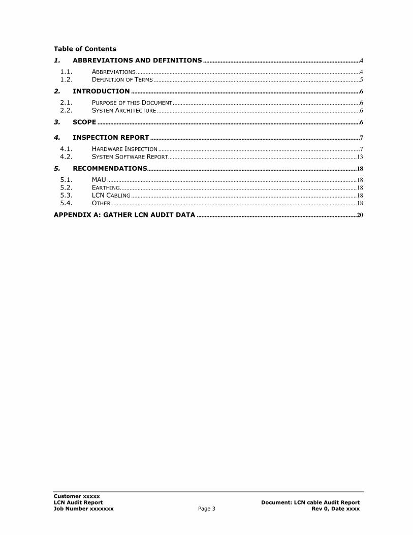
Table of Contents
1. ABBREVIATIONS AND DEFINITIONS ..................................................................................................4
1.1. ABBREVIATIONS ............................................................................................................................................4
1.2. DEFINITION OF TERMS .................................................................................................................................5
2. INTRODUCTION ...............................................................................................................................................6
2.1. PURPOSE OF THIS DOCUMENT .....................................................................................................................6
2.2. SYSTEM ARCHITECTURE ...............................................................................................................................6
3. SCOPE ....................................................................................................................................................................6
4. INSPECTION REPORT ...................................................................................................................................7
4.1. HARDWARE INSPECTION ..............................................................................................................................7
4.2. SYSTEM SOFTWARE REPORT...................................................................................................................... 13
5. RECOMMENDATIONS................................................................................................................................... 18
5.1. MAU ............................................................................................................................................................ 18
5.2. EARTHING .................................................................................................................................................... 18
5.3. LCN CABLING ............................................................................................................................................. 18
5.4. OTHER ......................................................................................................................................................... 18
APPENDIX A: GATHER LCN AUDIT DATA .................................................................................................... 20
Customer xxxxx
LCN Audit Report Document: LCN cable Audit Report Job Number xxxxxxx Page 4 Rev 0, Date xxxx
1. Abbreviations and Definitions
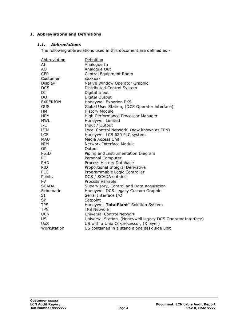
1.1. Abbreviations
The following abbreviations used in this document are defined as:- Abbreviation Definition
AI Analogue In AO Analogue Out CER Central Equipment Room
Customer xxxxxxx Display Native Window Operator Graphic DCS Distributed Control System DI Digital Input
DO Digital Output EXPERION Honeywell Experion PKS GUS Global User Station, (DCS Operator interface) HM History Module HPM High-Performance Processor Manager HWL Honeywell Limited I/O Input / Output
LCN Local Control Network, (now known as TPN) LCS Honeywell LCS 620 PLC system MAU Media Access Unit NIM Network Interface Module
OP Output P&ID Piping and Instrumentation Diagram PC Personal Computer
PHD Process History Database PID Proportional Integral Derivative PLC Programmable Logic Controller Points DCS / SCADA entities
PV Process Variable SCADA Supervisory, Control and Data Acquisition Schematic Honeywell DCS Legacy Custom Graphic SI Serial Interface I/O
SP Setpoint TPS Honeywell TotalPlant Solution System
TPN TPS Network UCN Universal Control Network
US Universal Station, (Honeywell legacy DCS Operator interface) UxS US with a Unix Co-processor, (X layer) Workstation US contained in a stand alone desk side unit
Customer xxxxx
LCN Audit Report Document: LCN cable Audit Report Job Number xxxxxxx Page 5 Rev 0, Date xxxx
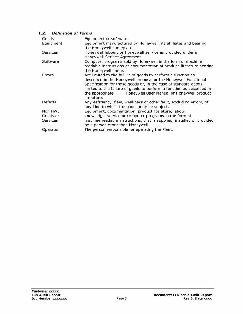
1.2. Definition of Terms
Goods Equipment or software. Equipment Equipment manufactured by Honeywell, its affiliates and bearing
the Honeywell nameplate. Services Honeywell labour, or Honeywell service as provided under a
Honeywell Service Agreement. Software Computer programs sold by Honeywell in the form of machine
readable instructions or documentation of produce literature bearing
the Honeywell name. Errors Are limited to the failure of goods to perform a function as
described in the Honeywell proposal or the Honeywell Functional Specification for those goods or, in the case of standard goods,
limited to the failure of goods to perform a function as described in the appropriate Honeywell User Manual or Honeywell product literature.
Defects Any deficiency, flaw, weakness or other fault, excluding errors, of
any kind to which the goods may be subject. Non HWL Equipment, documentation, product literature, labour, Goods or knowledge, service or computer programs in the form of
Services machine readable instructions, that is supplied, installed or provided by a person other than Honeywell.
Operator The person responsible for operating the Plant.
Customer xxxxx
LCN Audit Report Document: LCN cable Audit Report Job Number xxxxxxx Page 6 Rev 0, Date xxxx
2. Introduction
2.1. Purpose of this Document
The purpose of this LCN audit is to generate a report and suggested corrective actions to be taken based on an inspection done at the xxxxxxxxx. This document is to be reviewed and approved by the Customer.
2.2. System Architecture
The Control System at xxxxxxxx consists of Universal stations, GUS, Application Modules,
APP Nodes, Highway Gateways, Network Interface Modules, History Modules, Experion Servers and Experion Stations. The current LCN version at xxxxxxxx is Rxxxxxx.
The Local Control Network (LCN) is a token bus network that is implemented in 75 ohm coaxial cable. The bus is terminated at each end and each node on the bus is transformer isolated from the bus. The LCN has two physically separate redundant copies, LCN A and
LCN B, so there are actually two networks. The Operator Consoles in the control room uses Group, Trend, Detail and Custom Displays
as the interface to mimic and control the plant.
3. Scope
The scope of work for this audit;
• Inspect and document all LCN Connections. • Inspect and review all MAU devices on the LCN.
• Inspect and document all LCN node earthing. • Review and summarise all LCN Error statistics. • Review and document any standing System alarms. • Review and document all current history module journals for System errors.
This is a passive audit where no active testing of cabling, system testing or performing any interruptions to the LCN cables was under taken.
Customer xxxxx
LCN Audit Report Document: LCN cable Audit Report Job Number xxxxxxx Page 7 Rev 0, Date xxxx
4. Inspection report
The inspection report is divided into two sections: The first section is detailed as the hardware inspection and the second section is the review of the system diagnostics and system journals.
4.1. Hardware Inspection
Below is a summary of the equipment inspected. Appendix A is an Excel spreadsheet containing all the information on the LCN hardware inspection.
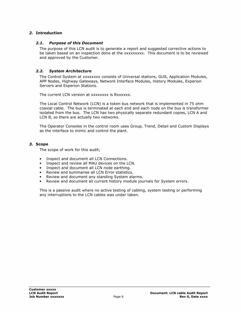
4.1.1. Media Access Units
All MAU’s founded are the newer type i.e. case manufactured from aluminium. Details are found in BeAware advice BW 98010. A copy of the
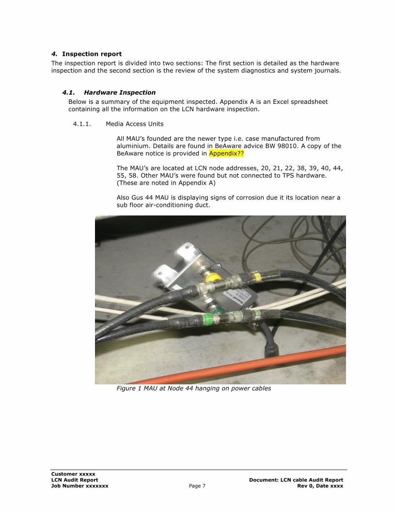
BeAware notice is provided in Appendix?? The MAU’s are located at LCN node addresses, 20, 21, 22, 38, 39, 40, 44, 55, 58. Other MAU’s were found but not connected to TPS hardware. (These are noted in Appendix A) Also Gus 44 MAU is displaying signs of corrosion due it its location near a
sub floor air-conditioning duct.
Figure 1 MAU at Node 44 hanging on power cables
Customer xxxxx
LCN Audit Report Document: LCN cable Audit Report Job Number xxxxxxx Page 8 Rev 0, Date xxxx
Figure 2 MAU at Node 44 show signs of corrosion
4.1.2. LCN Grounding Principles
xxxxxxx uses Non CE equipment and the following must apply on the grounding of equipment: The required grounds and their connections including design are discussed
below; Five-Slot Modules are grounded according to the type of node present in the module. Universal Stations have the logic ground terminal connected to chassis ground. All other LCN nodes have the logic ground connected to MRG.
Dual Node Modules require grounding of both nodes in the module according to the type of node present in the module.
• Hiway Gateways (HG) have the logic ground connected to MRG.
• All other node types have the logic terminal connected to chassis ground.
• Redundant gateways (HGs, NIMs, and PLCGs) must be located in
separated Dual Node Modules.
For safety reasons the outer conductor of the coaxial cable is grounded to chassis at one location. The following items are noted as not meeting the requirements
• LCN cable earthing is not implemented. This should ground A and B cables and not to be grounded at the same node. LCN A and B
should be grounded in 37-CAB-LCN1 at NIM 23 or NIM 24
Customer xxxxx
LCN Audit Report Document: LCN cable Audit Report Job Number xxxxxxx Page 9 Rev 0, Date xxxx
respectively. They should also be grounded in 37-CAB-LCN6 at NIM
47 and NIM 48 respectively. *Note this connection can be made by installing CS/R I/O (51304286)
boards. The CS/R’s provide a connection from the BNC outer conductor to
chassis on the PWB. As this time we cannot confirm installation of these
boards based that the part number is not visible.
• LCN Cables are joined by Tee connectors, this is not recommended
for use of extending cable lengths. Only where a physical connection is required to a LCN node.
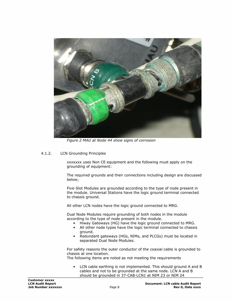
• On US stations, Logic and Chassis ground must be shorted, this is not implemented on nodes 5, 6, 8, 9, 31, 32, 33, 34, 35, 36, 37 (Also note node 8 has no chassis ground connection)
Figure 3 Unterminated Earth cabling from removed node.
Ground guidelines can be found in reference document; TPS System Site
planning (SW02-550) section 5.
4.1.3. HIWAY Grounding Principles
TDC HiWay systems will keep the Master Reference Ground and the Safety Ground. This is outside of scope for the LCN audit.
Customer xxxxx
LCN Audit Report Document: LCN cable Audit Report Job Number xxxxxxx Page 10 Rev 0, Date xxxx
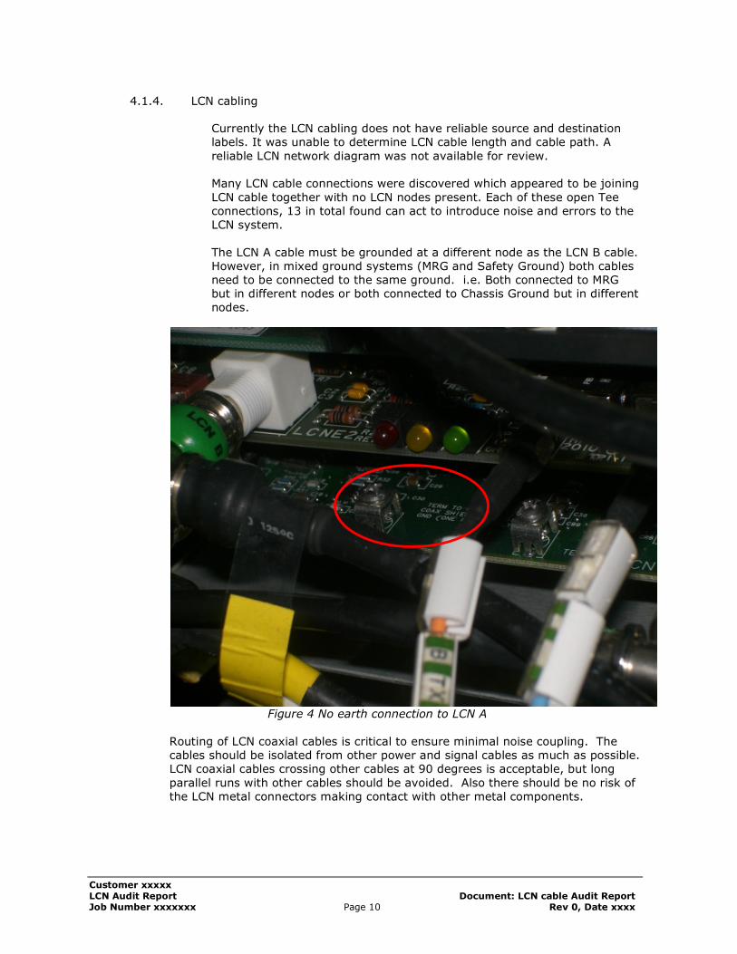
4.1.4. LCN cabling
Currently the LCN cabling does not have reliable source and destination labels. It was unable to determine LCN cable length and cable path. A
reliable LCN network diagram was not available for review. Many LCN cable connections were discovered which appeared to be joining
LCN cable together with no LCN nodes present. Each of these open Tee connections, 13 in total found can act to introduce noise and errors to the LCN system.
The LCN A cable must be grounded at a different node as the LCN B cable. However, in mixed ground systems (MRG and Safety Ground) both cables need to be connected to the same ground. i.e. Both connected to MRG but in different nodes or both connected to Chassis Ground but in different nodes.
Figure 4 No earth connection to LCN A
Routing of LCN coaxial cables is critical to ensure minimal noise coupling. The cables should be isolated from other power and signal cables as much as possible. LCN coaxial cables crossing other cables at 90 degrees is acceptable, but long
parallel runs with other cables should be avoided. Also there should be no risk of the LCN metal connectors making contact with other metal components.
Customer xxxxx
LCN Audit Report Document: LCN cable Audit Report Job Number xxxxxxx Page 11 Rev 0, Date xxxx
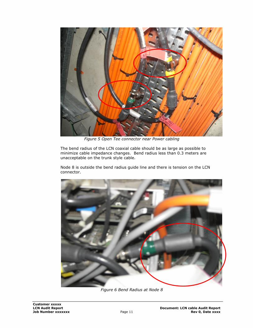
Figure 5 Open Tee connector near Power cabling
The bend radius of the LCN coaxial cable should be as large as possible to minimize cable impedance changes. Bend radius less than 0.3 meters are unacceptable on the trunk style cable.
Node 8 is outside the bend radius guide line and there is tension on the LCN connector.
Figure 6 Bend Radius at Node 8
Customer xxxxx
LCN Audit Report Document: LCN cable Audit Report Job Number xxxxxxx Page 12 Rev 0, Date xxxx
4.1.5. Environmental Conditions
The air conditioning in the Central Equipment Room (CER) should be checked regularly
System equipment operates over a wide range of temperature and humidity; however, corrosive process materials, contaminants in the air and other realistic considerations may reduce the environmental range
that can be placed on the equipment. The following guidelines limiting the operating ranges are recommended: • Maintain relative humidity levels between 40% and 50%.
• Control humidity fluctuations to less than 6% per hour rate-of-change. • Limit the temperature rate-of-change to 1°C/minute on actuation of
the air conditioner. The system at Xxxxxxx is monitored and alarms are generated to warn if the air conditioner is not operating correctly.
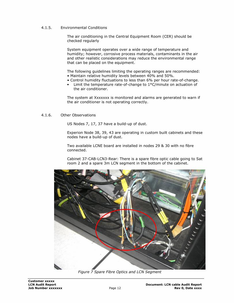
4.1.6. Other Observations
US Nodes 7, 17, 37 have a build-up of dust.
Experion Node 38, 39, 43 are operating in custom built cabinets and these nodes have a build-up of dust.
Two available LCNE board are installed in nodes 29 & 30 with no fibre connected.
Cabinet 37-CAB-LCN3-Rear: There is a spare fibre optic cable going to Sat room 2 and a spare 3m LCN segment in the bottom of the cabinet.
Figure 7 Spare Fibre Optics and LCN Segment
Customer xxxxx
LCN Audit Report Document: LCN cable Audit Report Job Number xxxxxxx Page 13 Rev 0, Date xxxx
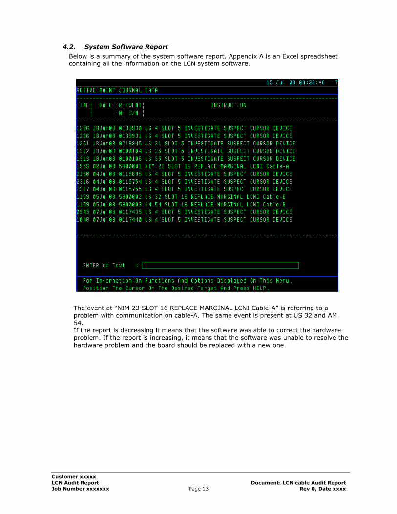
4.2. System Software Report
Below is a summary of the system software report. Appendix A is an Excel spreadsheet containing all the information on the LCN system software.
The event at “NIM 23 SLOT 16 REPLACE MARGINAL LCNI Cable-A” is referring to a
problem with communication on cable-A. The same event is present at US 32 and AM 54. If the report is decreasing it means that the software was able to correct the hardware problem. If the report is increasing, it means that the software was unable to resolve the hardware problem and the board should be replaced with a new one.
Customer xxxxx
LCN Audit Report Document: LCN cable Audit Report Job Number xxxxxxx Page 14 Rev 0, Date xxxx
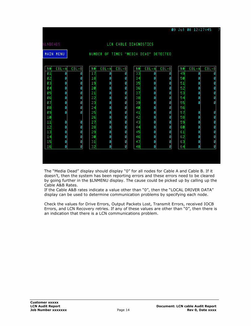
The “Media Dead” display should display “0” for all nodes for Cable A and Cable B. If it doesn’t, then the system has been reporting errors and these errors need to be cleared by going further in the $LNMENU display. The cause could be picked up by calling up the Cable A&B Rates.
If the Cable A&B rates indicate a value other than “0”, then the “LOCAL DRIVER DATA” display can be used to determine communication problems by specifying each node.
Check the values for Drive Errors, Output Packets Lost, Transmit Errors, received IOCB Errors, and LCN Recovery retries. If any of these values are other than “0”, then there is an indication that there is a LCN communications problem.
Customer xxxxx
LCN Audit Report Document: LCN cable Audit Report Job Number xxxxxxx Page 15 Rev 0, Date xxxx
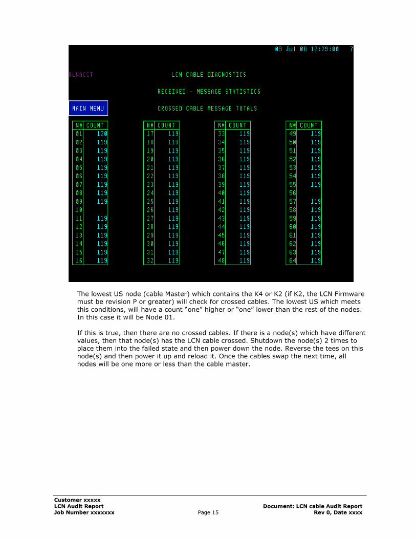
The lowest US node (cable Master) which contains the K4 or K2 (if K2, the LCN Firmware must be revision P or greater) will check for crossed cables. The lowest US which meets
this conditions, will have a count “one” higher or “one” lower than the rest of the nodes. In this case it will be Node 01.
If this is true, then there are no crossed cables. If there is a node(s) which have different values, then that node(s) has the LCN cable crossed. Shutdown the node(s) 2 times to place them into the failed state and then power down the node. Reverse the tees on this node(s) and then power it up and reload it. Once the cables swap the next time, all
nodes will be one more or less than the cable master.
Customer xxxxx
LCN Audit Report Document: LCN cable Audit Report Job Number xxxxxxx Page 16 Rev 0, Date xxxx
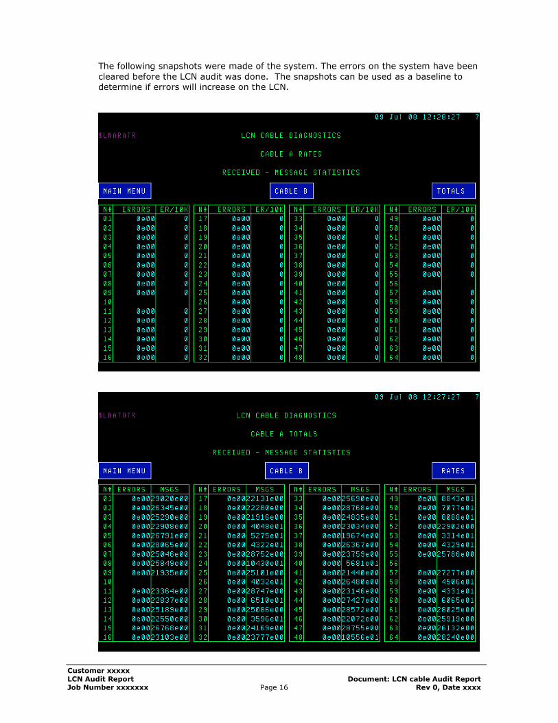
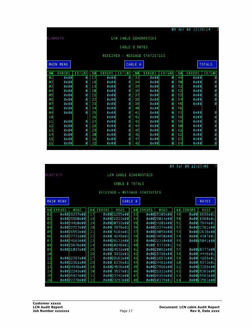
The following snapshots were made of the system. The errors on the system have been
cleared before the LCN audit was done. The snapshots can be used as a baseline to determine if errors will increase on the LCN.
Customer xxxxx
LCN Audit Report Document: LCN cable Audit Report Job Number xxxxxxx Page 17 Rev 0, Date xxxx
Customer xxxxx
LCN Audit Report Document: LCN cable Audit Report Job Number xxxxxxx Page 18 Rev 0, Date xxxx
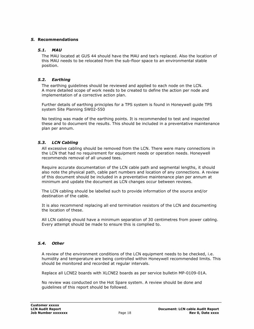
5. Recommendations
5.1. MAU
The MAU located at GUS 44 should have the MAU and tee’s replaced. Also the location of this MAU needs to be relocated from the sub-floor space to an environmental stable
position.
5.2. Earthing
The earthing guidelines should be reviewed and applied to each node on the LCN. A more detailed scope of work needs to be created to define the action per node and implementation of a corrective action plan.
Further details of earthing principles for a TPS system is found in Honeywell guide TPS system Site Planning SW02-550 No testing was made of the earthing points. It is recommended to test and inspected
these and to document the results. This should be included in a preventative maintenance plan per annum.
5.3. LCN Cabling
All excessive cabling should be removed from the LCN. There were many connections in the LCN that had no requirement for equipment needs or operation needs. Honeywell recommends removal of all unused tees.
Require accurate documentation of the LCN cable path and segmental lengths, it should also note the physical path, cable part numbers and location of any connections. A review
of this document should be included in a preventative maintenance plan per annum at minimum and update the document as LCN changes occur between reviews. The LCN cabling should be labelled such to provide information of the source and/or
destination of the cable. It is also recommend replacing all end termination resistors of the LCN and documenting the location of these.
All LCN cabling should have a minimum separation of 30 centimetres from power cabling. Every attempt should be made to ensure this is complied to.
5.4. Other
A review of the environment conditions of the LCN equipment needs to be checked, i.e. humidity and temperature are being controlled within Honeywell recommended limits. This should be monitored and recorded at regular intervals.
Replace all LCNE2 boards with XLCNE2 boards as per service bulletin MP-0109-01A. No review was conducted on the Hot Spare system. A review should be done and guidelines of this report should be followed.
Customer xxxxx
LCN Audit Report Document: LCN cable Audit Report Job Number xxxxxxx Page 19 Rev 0, Date xxxx
Once all of the recommendations are actioned a review should be conducted again to
measure impact of changes and stability of LCN communications. If no improvements are observed in the LCN communications then further testing needs to be conducted. This could include but not limited to LCN Noise measurements, LCN cable
testing, and active testing of the earthing system.
Customer xxxxx
LCN Audit Report Document: LCN cable Audit Report Job Number xxxxxxx Page 20 Rev 0, Date xxxx
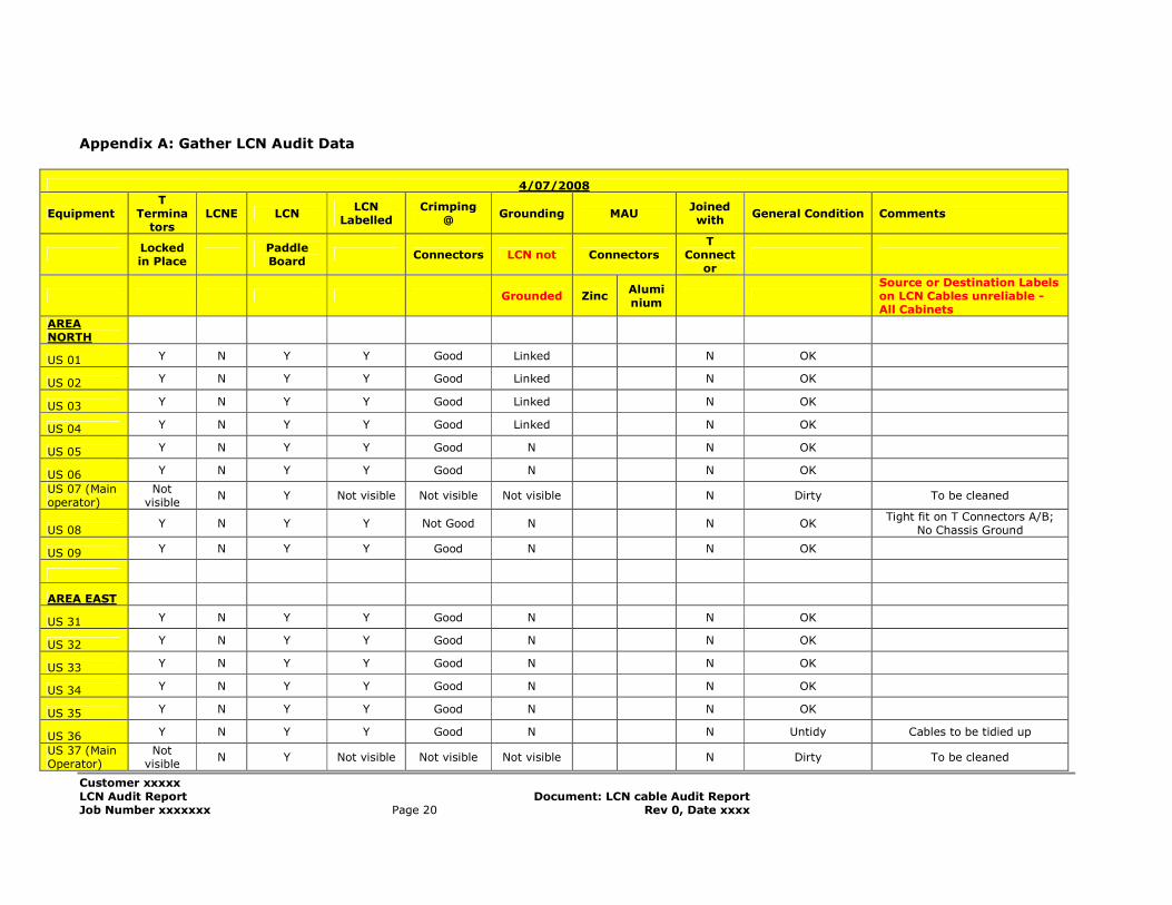
Appendix A: Gather LCN Audit Data
4/07/2008
Equipment T
Terminators
LCNE LCN LCN
Labelled Crimping
@ Grounding MAU
Joined with
General Condition Comments
Locked in Place
Paddle Board
Connectors LCN not Connectors T
Connector
Grounded Zinc Alumi
nium
Source or Destination Labels on LCN Cables unreliable - All Cabinets
AREA NORTH
US 01 Y N Y Y Good Linked N OK
US 02 Y N Y Y Good Linked N OK
US 03 Y N Y Y Good Linked N OK
US 04 Y N Y Y Good Linked N OK
US 05 Y N Y Y Good N N OK
US 06 Y N Y Y Good N N OK
US 07 (Main operator)
Not visible
N Y Not visible Not visible Not visible N Dirty To be cleaned
US 08 Y N Y Y Not Good N N OK
Tight fit on T Connectors A/B; No Chassis Ground
US 09 Y N Y Y Good N N OK
AREA EAST
US 31 Y N Y Y Good N N OK
US 32 Y N Y Y Good N N OK
US 33 Y N Y Y Good N N OK
US 34 Y N Y Y Good N N OK
US 35 Y N Y Y Good N N OK
US 36 Y N Y Y Good N N Untidy Cables to be tidied up
US 37 (Main Operator)
Not visible
N Y Not visible Not visible Not visible N Dirty To be cleaned
Customer xxxxx
LCN Audit Report Document: LCN cable Audit Report Job Number xxxxxxx Page 21 Rev 0, Date xxxx
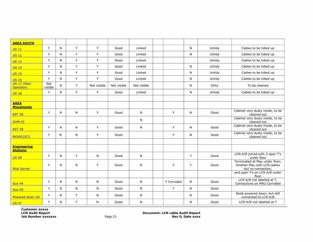
AREA SOUTH
US 11 Y N Y Y Good Linked N Untidy Cables to be tidied up
US 12 Y N Y Y Good Linked N Untidy Cables to be tidied up
US 13 Y N Y Y Good Linked Untidy Cables to be tidied up
US 14 Y N Y Y Good Linked N Untidy Cables to be tidied up
US 15 Y N Y Y Good Linked N Untidy Cables to be tidied up
US 16 Y N Y Y Good Linked N Untidy Cables to be tidied up
US 17 (Main Operator)
Not visible
N Y Not visible Not visible Not visible N Dirty To be cleaned
US 18 Y N Y Y Good Linked N Untidy Cables to be tidied up
AREA Movements
EST 38 Y N N Y Good N Y N Good
Cabinet very dusty inside, to be cleaned out
DVM 43 N
Cabinet very dusty inside, to be cleaned out
EST 39 Y N N Y Good N Y N Good
Cabinet very dusty inside, to be cleaned out
MOVECOC3 Y N N Y Good Y N Good
Cabinet very dusty inside, to be cleaned out
Engineering
Stations
US 09 Y N Y N Good N Y Good
LCN A/B joined with 3 open T's
under floor
Pilot Server Y N N Y Good N Y Y Good
Terminated at Mau under floor;
Another Mau with LCN cables but no connection,
and open T's on LCN A/B under floor
Gus 44 Y N N N Good N Y Corroded N Good
LCN A/B not labelled at T, Connections on MAU Corroded
Gus 40 Y N N N Good N Y N Good
Powered down US Y N Y N Good N N Good
Node powered down, but still connected to LCN A/B
US 41 Y N Y N Good N N Good LCN A/B not labelled at T
Customer xxxxx
LCN Audit Report Document: LCN cable Audit Report Job Number xxxxxxx Page 22 Rev 0, Date xxxx
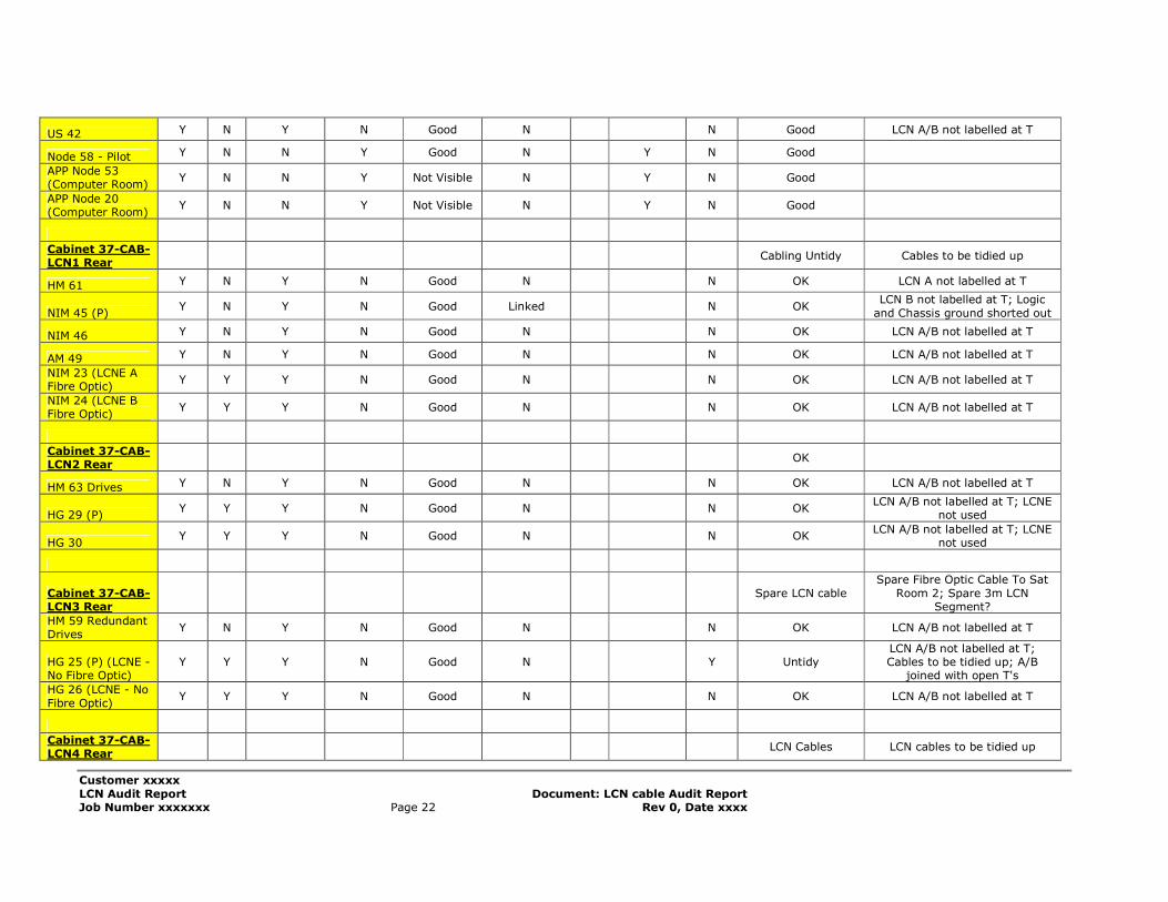
US 42 Y N Y N Good N N Good LCN A/B not labelled at T
Node 58 - Pilot Y N N Y Good N Y N Good
APP Node 53 (Computer Room)
Y N N Y Not Visible N Y N Good
APP Node 20 (Computer Room)
Y N N Y Not Visible N Y N Good
Cabinet 37-CAB-LCN1 Rear
Cabling Untidy Cables to be tidied up
HM 61 Y N Y N Good N N OK LCN A not labelled at T
NIM 45 (P) Y N Y N Good Linked N OK
LCN B not labelled at T; Logic
and Chassis ground shorted out
NIM 46 Y N Y N Good N N OK LCN A/B not labelled at T
AM 49 Y N Y N Good N N OK LCN A/B not labelled at T
NIM 23 (LCNE A Fibre Optic)
Y Y Y N Good N N OK LCN A/B not labelled at T
NIM 24 (LCNE B Fibre Optic)
Y Y Y N Good N N OK LCN A/B not labelled at T
Cabinet 37-CAB-LCN2 Rear
OK
HM 63 Drives Y N Y N Good N N OK LCN A/B not labelled at T
HG 29 (P) Y Y Y N Good N N OK
LCN A/B not labelled at T; LCNE not used
HG 30 Y Y Y N Good N N OK
LCN A/B not labelled at T; LCNE not used
Cabinet 37-CAB-LCN3 Rear
Spare LCN cable
Spare Fibre Optic Cable To Sat
Room 2; Spare 3m LCN Segment?
HM 59 Redundant Drives
Y N Y N Good N N OK LCN A/B not labelled at T
HG 25 (P) (LCNE -No Fibre Optic)
Y Y Y N Good N Y Untidy LCN A/B not labelled at T; Cables to be tidied up; A/B
joined with open T's
HG 26 (LCNE - No
Fibre Optic) Y Y Y N Good N N OK LCN A/B not labelled at T
Cabinet 37-CAB-LCN4 Rear
LCN Cables LCN cables to be tidied up
Customer xxxxx
LCN Audit Report Document: LCN cable Audit Report Job Number xxxxxxx Page 23 Rev 0, Date xxxx
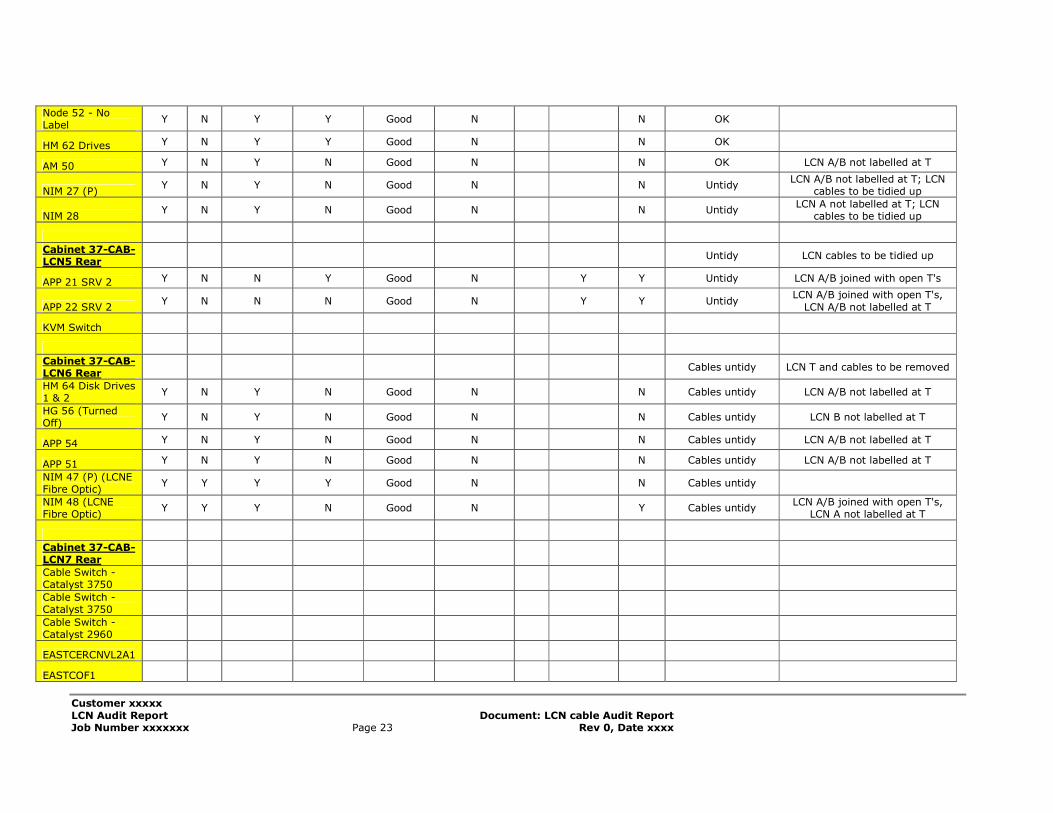
Node 52 - No Label
Y N Y Y Good N N OK
HM 62 Drives Y N Y Y Good N N OK
AM 50 Y N Y N Good N N OK LCN A/B not labelled at T
NIM 27 (P) Y N Y N Good N N Untidy
LCN A/B not labelled at T; LCN cables to be tidied up
NIM 28 Y N Y N Good N N Untidy
LCN A not labelled at T; LCN cables to be tidied up
Cabinet 37-CAB-LCN5 Rear
Untidy LCN cables to be tidied up
APP 21 SRV 2 Y N N Y Good N Y Y Untidy LCN A/B joined with open T's
APP 22 SRV 2 Y N N N Good N Y Y Untidy
LCN A/B joined with open T's,
LCN A/B not labelled at T
KVM Switch
Cabinet 37-CAB-LCN6 Rear
Cables untidy LCN T and cables to be removed
HM 64 Disk Drives 1 & 2
Y N Y N Good N N Cables untidy LCN A/B not labelled at T
HG 56 (Turned Off)
Y N Y N Good N N Cables untidy LCN B not labelled at T
APP 54 Y N Y N Good N N Cables untidy LCN A/B not labelled at T
APP 51 Y N Y N Good N N Cables untidy LCN A/B not labelled at T
NIM 47 (P) (LCNE Fibre Optic)
Y Y Y Y Good N N Cables untidy
NIM 48 (LCNE Fibre Optic)
Y Y Y N Good N Y Cables untidy LCN A/B joined with open T's,
LCN A not labelled at T
Cabinet 37-CAB-LCN7 Rear
Cable Switch - Catalyst 3750
Cable Switch - Catalyst 3750
Cable Switch - Catalyst 2960
EASTCERCNVL2A1
EASTCOF1
Customer xxxxx
LCN Audit Report Document: LCN cable Audit Report Job Number xxxxxxx Page 24 Rev 0, Date xxxx
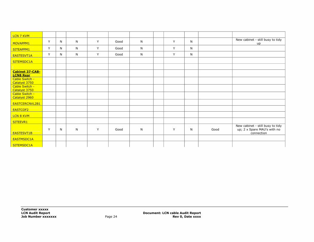
LCN 7 KVM
MOVAPPM1 Y N N Y Good N Y N
New cabinet - still busy to tidy up
SITEAPPM1 Y N N Y Good N Y N
EASTESVT1A Y N N Y Good N Y N
SITEMSDC1A
Cabinet 37-CAB-LCN8 Rear
Cable Switch - Catalyst 3750
Cable Switch - Catalyst 3750
Cable Switch - Catalyst 2960
EASTCERCNVL2B1
EASTCOF2
LCN 8 KVM
SITEEVR1
EASTESVT1B Y N N Y Good N Y N Good
New cabinet - still busy to tidy
up; 2 x Spare MAU's with no connection
EASTMSDC1A
SITEMSDC1A
Customer xxxxx
LCN Audit Report Document: LCN cable Audit Report Job Number xxxxxxx Page 25 Rev 0, Date xxxx
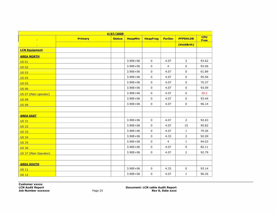
4/07/2008
Primary Status HeapMin HeapFrag ParSec PFPSHLDB CPU Free
(HoldBrth)
LCN Equipment
AREA NORTH
US 01 3.90E+06 0 4.07 2 93.62
US 02 3.90E+06 0 4 0 93.06
US 03 3.90E+06 0 4.07 0 61.89
US 04 3.90E+06 0 4.07 0 95.56
US 05 3.90E+06 0 4.07 0 70.37
US 06 3.90E+06 0 4.07 0 93.09
US 07 (Main operator) 3.90E+06 0 4.07 0 20.2
US 08 3.90E+06 0 4.07 0 93.44
US 09 3.90E+06 0 4.07 0 96.14
AREA EAST
US 31 3.90E+06 0 4.07 2 92.63
US 32 3.90E+06 0 4.07 15 95.82
US 33 3.90E+06 0 4.07 1 79.36
US 34 3.90E+06 0 4.33 2 92.09
US 35 3.90E+06 0 4 1 94.03
US 36 3.90E+06 0 4.07 0 82.11
US 37 (Main Operator) 3.90E+06 0 4.07 2 92.79
AREA SOUTH
US 11 3.90E+06 0 4.33 0 93.14
US 12 3.90E+06 0 4.07 1 96.26
Customer xxxxx
LCN Audit Report Document: LCN cable Audit Report Job Number xxxxxxx Page 26 Rev 0, Date xxxx
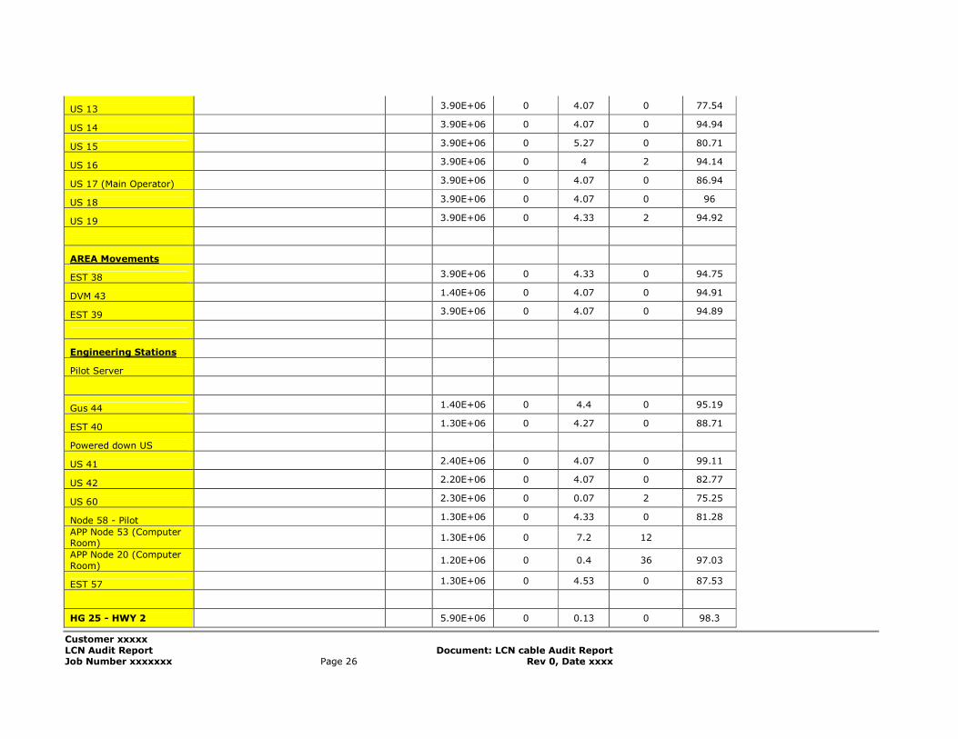
US 13 3.90E+06 0 4.07 0 77.54
US 14 3.90E+06 0 4.07 0 94.94
US 15 3.90E+06 0 5.27 0 80.71
US 16 3.90E+06 0 4 2 94.14
US 17 (Main Operator) 3.90E+06 0 4.07 0 86.94
US 18 3.90E+06 0 4.07 0 96
US 19 3.90E+06 0 4.33 2 94.92
AREA Movements
EST 38 3.90E+06 0 4.33 0 94.75
DVM 43 1.40E+06 0 4.07 0 94.91
EST 39 3.90E+06 0 4.07 0 94.89
Engineering Stations
Pilot Server
Gus 44 1.40E+06 0 4.4 0 95.19
EST 40 1.30E+06 0 4.27 0 88.71
Powered down US
US 41 2.40E+06 0 4.07 0 99.11
US 42 2.20E+06 0 4.07 0 82.77
US 60 2.30E+06 0 0.07 2 75.25
Node 58 - Pilot 1.30E+06 0 4.33 0 81.28
APP Node 53 (Computer Room)
1.30E+06 0 7.2 12
APP Node 20 (Computer
Room) 1.20E+06 0 0.4 36 97.03
EST 57 1.30E+06 0 4.53 0 87.53
HG 25 - HWY 2 5.90E+06 0 0.13 0 98.3
Customer xxxxx
LCN Audit Report Document: LCN cable Audit Report Job Number xxxxxxx Page 27 Rev 0, Date xxxx
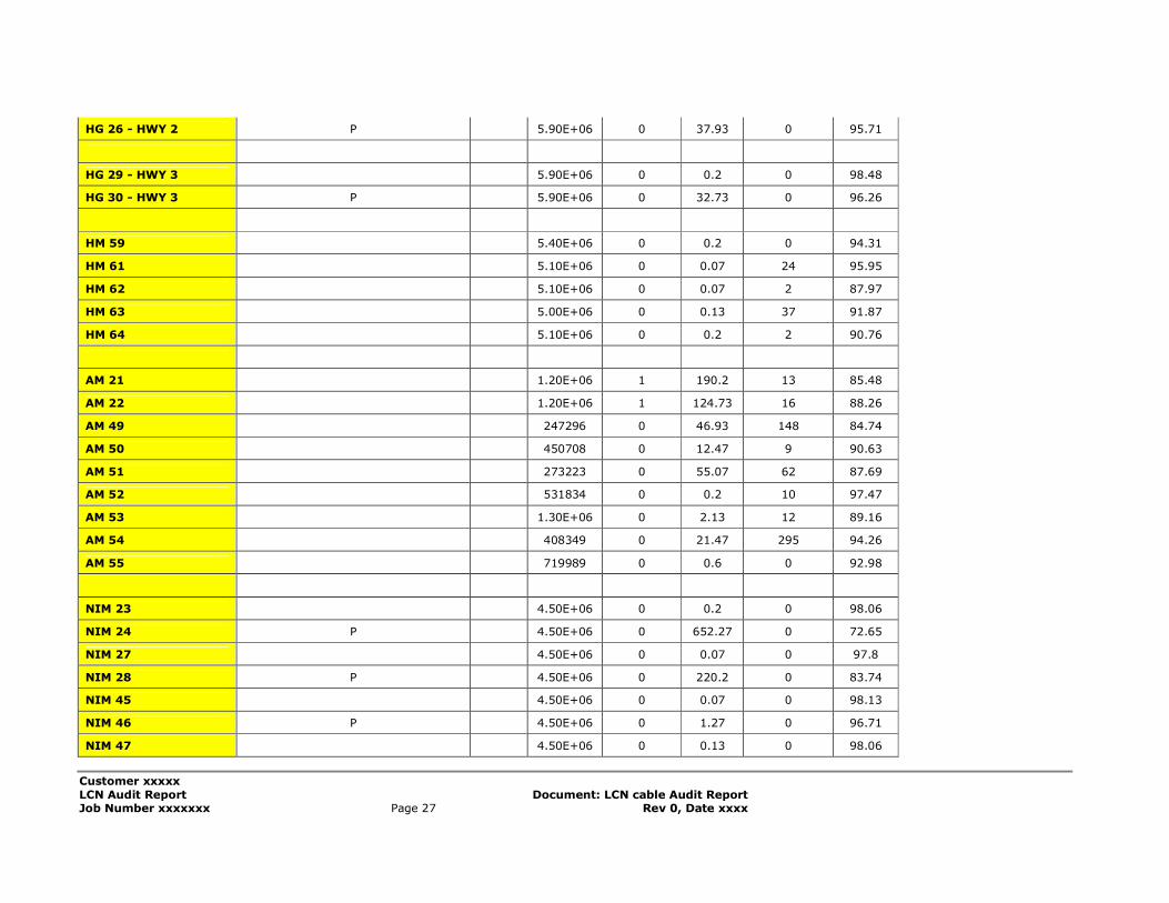
HG 26 - HWY 2 P 5.90E+06 0 37.93 0 95.71
HG 29 - HWY 3 5.90E+06 0 0.2 0 98.48
HG 30 - HWY 3 P 5.90E+06 0 32.73 0 96.26
HM 59 5.40E+06 0 0.2 0 94.31
HM 61 5.10E+06 0 0.07 24 95.95
HM 62 5.10E+06 0 0.07 2 87.97
HM 63 5.00E+06 0 0.13 37 91.87
HM 64 5.10E+06 0 0.2 2 90.76
AM 21 1.20E+06 1 190.2 13 85.48
AM 22 1.20E+06 1 124.73 16 88.26
AM 49 247296 0 46.93 148 84.74
AM 50 450708 0 12.47 9 90.63
AM 51 273223 0 55.07 62 87.69
AM 52 531834 0 0.2 10 97.47
AM 53 1.30E+06 0 2.13 12 89.16
AM 54 408349 0 21.47 295 94.26
AM 55 719989 0 0.6 0 92.98
NIM 23 4.50E+06 0 0.2 0 98.06
NIM 24 P 4.50E+06 0 652.27 0 72.65
NIM 27 4.50E+06 0 0.07 0 97.8
NIM 28 P 4.50E+06 0 220.2 0 83.74
NIM 45 4.50E+06 0 0.07 0 98.13
NIM 46 P 4.50E+06 0 1.27 0 96.71
NIM 47 4.50E+06 0 0.13 0 98.06
Customer xxxxx
LCN Audit Report Document: LCN cable Audit Report Job Number xxxxxxx Page 28 Rev 0, Date xxxx
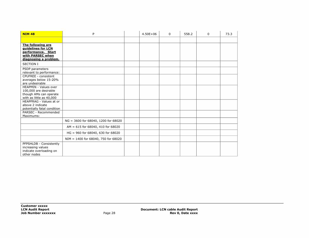
NIM 48 P 4.50E+06 0 558.2 0 73.3
The following are guidelines for LCN performance. Start with PARSEC when
diagnosing a problem.
SECTION I
PSDP parameters relevant to performance:
CPUFREE - consistent averages below 15-20%
are undesirable
HEAPMIN - Values over
100,000 are desirable though AMs can operate with as little as 40,000
HEAPFRAG - Values at or above 2 indicate potentially fatal condition
PARSEC - Recommended Maximums:
NG = 3600 for 68040, 1200 for 68020
AM = 615 for 68040, 410 for 68020
HG = 960 for 68040, 630 for 68020
NIM = 1400 for 68040, 750 for 68020
PFPSHLDB - Consistently increasing values indicate overloading on other nodes