Embed Size (px)
Citation preview

Krimotat, A., Sheng, L. "Structural Modeling." Bridge Engineering Handbook. Ed. Wai-Fah Chen and Lian Duan Boca Raton: CRC Press, 2000

8Structural Modeling
8.1 Introduction
8.2 Theoretical Background
8.3 ModelingSelection of Modeling Methodology • Geometry • Material and Section Properties • Boundary Conditions • Loads
8.4 Summary
8.1 Introduction
Prior to construction of any structural system, an extensive engineering design and analysis processmust be undertaken. During this process, many engineering assumptions are routinely used in theapplication of engineering principles and theories to practice. A subset of these assumptions is usedin a multitude of analytical methods available to structural analysts. In the modern engineeringoffice, with the proliferation and increased power of personal computers, increasing numbers ofengineers depend on structural analysis computer software to solve their engineering problems.This modernization of the engineering design office, coupled with an increased demand placed onthe accuracy and efficiency of structural designs, requires a more-detailed understanding of thebasic principles and assumptions associated with the use of modern structural analysis computerprograms. The most popular of these programs are GT STRUDL, STAADIII, SAP2000, as well assome more powerful and complex tools such as ADINA, ANSYS, NASTRAN, and ABAQUS.
The objective of the analysis effort is to investigate the most probable responses of a bridgestructure due to a range of applied loads. The results of these investigations must then be convertedto useful design data, thereby providing designers with the information necessary to evaluate theperformance of the bridge structure and to determine the appropriate actions in order to achievethe most efficient design configuration. Additionally, calculation of the structural system capacitiesis an important aspect in determining the most reliable design alternative. Every effort must bemade to ensure that all work performed during any analytical activity enables designers to producea set of quality construction documents including plans, specifications, and estimates.
The purpose of this chapter is to present basic modeling principles and suggest some guidelinesand considerations that should be taken into account during the structural modeling process.Additionally, some examples of numerical characterizations of selected bridge structures and theircomponents are provided. The outline of this chapter follows the basic modeling process. First, theselection of modeling methodology is discussed, followed by a description of the structural geom-etry, definition of the material and section properties of the components making up the structure,and description of the boundary conditions and loads acting on the structure.
Alexander KrimotatSC Solutions, Inc.
Li-Hong ShengCalifornia Department of Transportation
© 2000 by CRC Press LLC

8.2 Theoretical Background
Typically, during the analytical phase of any bridge design, finite-element-based structural analysisprograms are used to evaluate the structural integrity of the bridge system. Most structural analysisprograms employ sound, well-established finite-element methodologies and algorithms to solve theanalytical problem. Others employ such methods as moment distribution, column analogy, virtualwork, finite difference, and finite strip, to name a few. It is of utmost importance for the users ofthese programs to understand the theories, assumptions, and limitations of numerical modelingusing the finite-element method, as well as the limitations on the accuracy of the computer systemsused to execute these programs. Many textbooks [1, 4, 6] are available to study the theories andapplication of finite-element methodologies to practical engineering problems. It is strongly rec-ommended that examination of these textbooks be made prior to using finite-element-based com-puter programs for any project work. For instance, when choosing the types of elements to usefrom the finite-element library, the user must consider some important factors such as the basic setof assumptions used in the element formulation, the types of behavior that each element typecaptures, and the limitations on the physical behavior of the system.
Other important issues to consider include numerical solution techniques used in matrix oper-ations, computer numerical precision limitations, and solution methods used in a given analysis.There are many solution algorithms that employ direct or iterative methods, and sparse solvertechnology for solving the same basic problems; however, selecting these solution methods efficientlyrequires the user to understand the best conditions in which to apply each method and the basisor assumptions involved with each method. Understanding the solution parameters such as toler-ances for iterative methods and how they can affect the accuracy of a solution are also important,especially during the nonlinear analysis process.
Dynamic analysis is increasingly being required by many design codes today, especially in regionsof high seismicity. Response spectrum analysis is frequently used and easily performed with today’sanalysis tools; however, a basic understanding of structural dynamics is crucial for obtaining theproper results efficiently and interpreting analysis responses. Basic linear structural dynamics theorycan be found in many textbooks [2,3]. While many analysis tools on the market today can performvery sophisticated analyses in a timely manner, the user too must be more savvy and knowledgeableto control the overall analysis effort and optimize the performance of such tools.
8.3 Modeling
8.3.1 Selection of Modeling Methodology
The technical approach taken by the engineer must be based on a philosophy of providing practicalanalysis in support of the design effort. Significant importance must be placed on the analysisprocedures by the entire design team. All of the analytical modeling, analysis, and interpretation ofresults must be based on sound engineering judgment and a solid understanding of fundamentalengineering principles. Ultimately, the analysis must validate the design.
Many factors contribute to determination of the modeling parameters. These factors should reflectissues such as the complexity of the structure under investigation, types of loads being examined,and, most importantly, the information needed to be obtained from the analysis in the most efficientand “design-friendly” formats. This section presents the basic principles and considerations forstructural modeling. It also provides examples of modeling options for the various bridge structuretypes.
A typical flowchart of the analysis process is presented in Figure 8.1. The technical approach tocomputer modeling is usually based on a logical progression. The first step in achieving a reliablecomputer model is to define a proper set of material and soil properties, based on published dataand site investigations. Second, critical components are assembled and tested numerically where
© 2000 by CRC Press LLC

validation of the performance of these components is considered important to the global modelresponse. Closed-form solutions or available test data are used for these validations.
The next step is the creation and numerical testing of subsystems such as the bridge towers,superstructure elements, or individual frames. Again, as in the previous step, simple procedures areused in parallel to validate computer models. Last, a full bridge model consisting of the bridgesubsystems is assembled and exercised. This final global model should include appropriate repre-sentation of construction sequence, soil and foundation boundary conditions, structural componentbehavior, and connection details.
Following the analysis and after careful examination of the analytical results, the data is postpro-cessed and provided to the designers for the purpose of checking the design and determining suitabledesign modifications, as necessary. Postprocessing might include computation of deck sectionresultant forces and moments, determination of extreme values of displacements for columns ortowers and deck, and recovery of forces of constraint between structural components. The entireprocess may be repeated to validate any modifications made, depending on the nature and signif-icance of such modifications.
An important part of the overall analytical procedure is determination of the capacities of thestructural members. A combination of engineering calculations, computer analyses, and testing isutilized in order to develop a comprehensive set of component and system capacities. The evaluationof the structural integrity of the bridge structure, its components, and their connections are thenconducted by comparing capacities with the demands calculated from the structural analysis.
Depending on the complexity of the structure under investigation and the nature of applied loads,two- or three-dimensional models can be utilized. In most cases, beam elements can be used tomodel structural elements of the bridge (Figure 8.2), so the component responses are presented inthe form of force and moment resultants. These results are normally associated with individualelement coordinate systems, thus simplifying the evaluations of these components. Normally, these
FIGURE 8.1 Typical analysis process.
MaterialDefinition and
Verification
ComponentDefinition and
Verification
Sub-SystemDefinition and
Verification
Global SystemDefinition and
Verification
ComponentTesting
HandCalculations
LocalModels
Frame PushoverAnalyses
Evaluation ofStructural Integrityof the System and
Components
Finalize Design
Capacity Calculations
Dem
and
Cal
cula
tions
© 2000 by CRC Press LLC

force resultants describe axial, shear, torsion, and bending actions at a given model location.Therefore, it is very important during the initial modeling stages to determine key locations ofinterest, so the model can be assembled such that important results can be obtained at theselocations. While it is convenient to use element coordinate systems for the evaluation of the struc-tural integrity of individual components, nodal results such as displacements and support reactionsare usually output in the global coordinate systems. Proper refinement of the components mustalso be considered since different mesh size can sometimes cause significant variations in results.A balance between mesh refinement and reasonable element aspect ratios must be maintained sothat the behavioral characteristics of the computer model is representative of the structure itsimulates. Also, mesh refinement considerations must be made in conjunction with the cost tomodel efficiency. Higher orders of accuracy in modeling often come at a cost of analysis turnaroundtime and overall model efficiency. The analyst must use engineering judgment to determine if thebenefits of mesh refinement justify the costs. For example, for the convenience in design of bridgedetails such as reinforcement bar cutoff, prestressing cable layouts, and section changes, the bridgesuperstructure is usually modeled with a high degree of refinement in the dead- and live-loadanalyses to achieve a well-defined force distribution. The same refinement may not be necessary ina dynamic analysis. Quite often, coarser models (at least four elements per span for the superstruc-ture and three elements per column) are used in the dynamic analyses. These refinements are theminimum guidelines for discrete lumped mass models in dynamic analysis to maintain a reasonablemass distribution during the numerical solution process.
For more complex structures with complicated geometric configurations, such as curved plategirder bridges (Figure 8.3), or bridges with highly skewed supports (Figure 8.4), more-detailedfinite-element models should be considered, especially if individual components within the super-structure need to be evaluated, which could not be facilitated with a beam superstructure repre-sentation. With the increasing speed of desktop computers, and advances in finite-element modelingtools, these models are becoming increasingly more popular. The main reason for their increasedpopularity is the improved accuracy, which in turn results in more efficient and cost-effective design.
FIGURE 8.2 Typical beam model.
© 2000 by CRC Press LLC

More complex models, however, require a significantly higher degree of engineering experienceand expertise in the theory and application of the finite-element method. In the case of a complexmodel, the engineer must determine the degree of refinement of the model. This determination isusually made based on the types of applied loads as well as the behavioral characteristics of thestructure being represented by the finite-element model. It is important to note that the format ofthe results obtained from detailed models, such as shell and three-dimensional (3D) continuummodels) is quite different from the results obtained from beam (or stick) models. Stresses and strainsare obtained for each of the bridge components at a much more detailed level; therefore, calculationof a total force applied to the superstructure, for example, becomes a more difficult, tedious task.However, evaluation of local component behavior, such as cross frames, plate girder sections, orbridge deck sections, can be accomplished directly from the analysis results of a detailed finite-element model.
FIGURE 8.3 Steel plate-girder bridge—finite-element model.
FIGURE 8.4 Concrete box girder with 45° skewed supports finite-element model.
© 2000 by CRC Press LLC

8.3.2 Geometry
After selecting an appropriate modeling methodology, serious considerations must be given toproper representation of the bridge geometric characteristics. These geometric issues are directlyrelated to the behavioral characteristics of the structural components as well as the overall globalstructure. The considerations must include not only the global geometry of the bridge structure,i.e., horizontal alignment, vertical elevation, superelevation of the roadway, and severity of thesupport skews, but local geometric characterizations of connection details of individual bridgecomponents as well. Such details include representations of connection regions such as column-to-cap beam, column-to-box girder, column-to-pile cap, cap beam to superstructure, cross frames toplate girder, gusset plates to adjacent structural elements, as well as various bearing systems com-monly used in bridge engineering practice. Some examples of some modeling details are demon-strated in Figures 8.5 through 8.11.
Specifically, Figure 8.5 demonstrates how a detailed model of a box girder bridge structure canbe assembled via use of shell elements (for girder webs and soffit), truss elements (for post-tensioning tendons), 3D solid elements (for internal diaphragms), and beam elements (for col-umns). Figure 8.6 illustrates some details of the web, deck, and abutment modeling for the samebridge structure. Additionally, spring elements are used to represent abutment support conditionsfor the vertical as well as back-wall directions. An example of a column and its connection to thesuperstructure in an explicit finite-element model is presented in the Figure 8.7. Three elements areused to represent the full length of the column. A set of rigid links connects the superstructure toeach of the supporting columns (Figures 8.8 and 8.9). This is necessary to properly transmit bending
FIGURE 8.5 Concrete box-girder modeling example (deck elements not shown).
© 2000 by CRC Press LLC
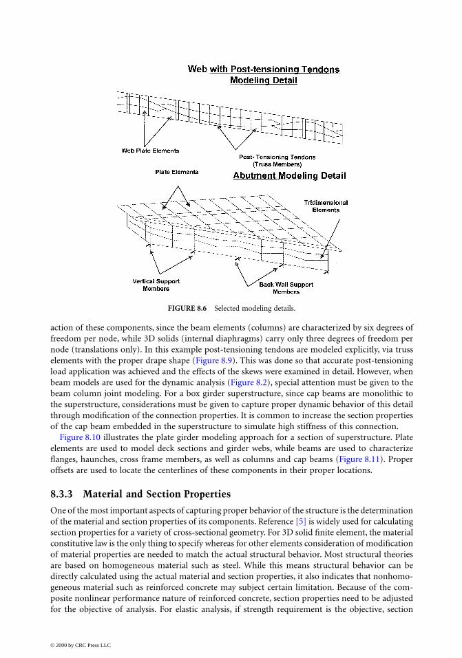
action of these components, since the beam elements (columns) are characterized by six degrees offreedom per node, while 3D solids (internal diaphragms) carry only three degrees of freedom pernode (translations only). In this example post-tensioning tendons are modeled explicitly, via trusselements with the proper drape shape (Figure 8.9). This was done so that accurate post-tensioningload application was achieved and the effects of the skews were examined in detail. However, whenbeam models are used for the dynamic analysis (Figure 8.2), special attention must be given to thebeam column joint modeling. For a box girder superstructure, since cap beams are monolithic tothe superstructure, considerations must be given to capture proper dynamic behavior of this detailthrough modification of the connection properties. It is common to increase the section propertiesof the cap beam embedded in the superstructure to simulate high stiffness of this connection.
Figure 8.10 illustrates the plate girder modeling approach for a section of superstructure. Plateelements are used to model deck sections and girder webs, while beams are used to characterizeflanges, haunches, cross frame members, as well as columns and cap beams (Figure 8.11). Properoffsets are used to locate the centerlines of these components in their proper locations.
8.3.3 Material and Section Properties
One of the most important aspects of capturing proper behavior of the structure is the determinationof the material and section properties of its components. Reference [5] is widely used for calculatingsection properties for a variety of cross-sectional geometry. For 3D solid finite element, the materialconstitutive law is the only thing to specify whereas for other elements consideration of modificationof material properties are needed to match the actual structural behavior. Most structural theoriesare based on homogeneous material such as steel. While this means structural behavior can bedirectly calculated using the actual material and section properties, it also indicates that nonhomo-geneous material such as reinforced concrete may subject certain limitation. Because of the com-posite nonlinear performance nature of reinforced concrete, section properties need to be adjustedfor the objective of analysis. For elastic analysis, if strength requirement is the objective, section
FIGURE 8.6 Selected modeling details.
© 2000 by CRC Press LLC

properties are less important as long as relative stiffness is correct. Section properties become mostcritical when structure displacement and deformation are objectives. Since concrete cracks beyondcertain deformation, section properties need to be modified for this behavior. In general, if ultimatedeformation is expected, then effective stiffness should be the consideration in section properties. Itis common to use half value of the moment of inertia for reinforced concrete members and full valuefor prestressed concrete members. To replicate a rigid member behavior such as cap beams, sectionproperties need to be amplified 100 times to eliminate local vibration problems in dynamic analysis.
Nonlinear behaviors are most difficult to handle in both complex and simple finite-elementmodels. When solid elements are used, the constitutive relationships describing material behavior
FIGURE 8.7 Bent region modeling detail.
FIGURE 8.8 Column-to-superstructure connection modeling detail.
© 2000 by CRC Press LLC

should be utilized. These properties should be calibrated by the data obtained from the availabletest experiments. For beam–column-type elements, however, it is essential that the engineer properlyestimates performance of the components either by experiments or theoretical detailed analysis.Once member performance is established, a simplified inelastic model can be used to simulate theexpected member behavior. Depending on the complexity of the member, bilinear, or multilinearmaterial representations may be used extensively. If member degradation needs to be incorporatedin the analysis, then the Takeda model may be used. While a degrading model can correlatetheoretical behavior with experimental results very well, elastic–plastic or bilinear models can givethe engineer a good estimate of structural behavior without detailed material property parameters.
When a nonlinear analysis is performed, the engineer needs to understand the sensitivity issueraised by such analysis techniques. Without a good understanding of member behavior, it is very
FIGURE 8.9 Post-tensioning tendons, diaphragms, and column-to-diaphragm connection modeling examples.
FIGURE 8.10 Plate girder superstructure modeling example.
© 2000 by CRC Press LLC

easy to fall into the “garbage in, garbage out” mode of operation. It is essential for the engineer toverify member behavior with known material properties before any production analyses are con-ducted. For initial design, all material properties should be based on the nominal values. However,it is important to verify the design with the expected material properties.
8.3.4 Boundary Conditions
Another key ingredient for the success of the structural analysis is the proper characterization ofthe boundary conditions of the structural system. Conditions of the columns or abutments at thesupport (or ground) points must be examined by engineers and properly implemented into thestructural analysis model. This can be accomplished via several means based on different engineeringassumptions. For example, during most of the static analysis, it is common to use a simple repre-sentation of supports (e.g., fixed, pinned, roller) without characterizations of the soil/foundationstiffness. However, for a dynamic analysis, proper representation of the soil/foundation system isessential (Figure 8.12). Most finite-element programs will accept a [6 × 6] stiffness matrix input forsuch system. Other programs require extended [12 × 12] stiffness matrix input describing therelationship between the ground point and the base of the columns. Prior to using these matrices,it is important that the user investigate the internal workings of the finite-element program, so theproper results are obtained by the analysis.
In some cases it is necessary to model the foundation/soil system with greater detail. Nonlinearmodeling of the system can be accomplished via nonlinear spring/damper representation(Figure 8.13) or, in the extreme case, by explicit modeling of subsurface elements and plasticity-based springs representing surrounding soil mass (Figure 8.14). It is important that if this degreeof detail is necessary, the structural engineer works very closely with the geotechnical engineers todetermine proper properties of the soil springs. As a general rule it is essential to set up smallmodels to test behavior and check the results via hand calculations.
FIGURE 8.11 Plate girder bent region modeling example.
© 2000 by CRC Press LLC

FIGURE 8.12 Examples of foundation modeling.
FIGURE 8.13 Nonlinear spring/damper model.
FIGURE 8.14 Soil–structure interaction modeling.
© 2000 by CRC Press LLC

8.3.5 Loads
During engineering design activities, computer models are used to evaluate bridge structures forvarious service loads, such as traffic, wind, thermal, construction, and other service loads. Theseservice loads can be represented by a series of static load cases applied to the structural model. Someexamples of application of the truck loads are presented in Figures 8.15 and 8.16.
In many cases, especially in high seismic zones, dynamic loads control many bridge designparameters. In this case, it is very important to understand the nature of these loads, as well as thetheory that governs the behavior of structural systems subjected to these dynamic loads. In highseismic zones, a multimode response spectrum analysis is required to evaluate the dynamic responseof bridge structures. In this case, the response spectrum loading is usually described by the rela-tionship of the structural period vs. ground acceleration, velocity, or displacement for a givenstructural damping. In some cases, usually for more complex bridge structures, a time historyanalysis is required. During these analytical investigations, a set of time history loads (normally,displacement or acceleration vs. time) is applied to the boundary nodes of the structure. Reference[3] is the most widely used theoretical reference related to the seismic analysis methodology foreither response spectrum or time history analysis.
8.4 Summary
In summary, the analysis effort should support the overall design effort by verifying the design andaddressing any issues with respect to the efficiency and the viability of the design. Before modelingcommences, the engineer must define the scope of the problem and ask what key results and typesof data he or she is interested in obtaining from the analytical model. With these basic parametersin mind, the engineer can then apply technical knowledge to formulate the simplest, most elegantmodel to represent the structure properly and provide the range of solutions that are accurate andfundamentally sound. The engineer must bound the demands on the structure by looking at limiting
FIGURE 8.15 Truck load application example.
© 2000 by CRC Press LLC

load cases and modifying the structure parameters, such as boundary conditions or material prop-erties. Rigorous testing of components, hand calculations, local modeling, and sound engineeringjudgment must be used to validate the analytical model at all levels. Through a rigorous analyticalmethodology and proper use of today’s analytical tools, structural engineers can gain a betterunderstanding of the behavior of the structure, evaluate the integrity of the structure, and validateand optimize the structural design.
References
1. Bathe, K.J., Finite Element Procedures, 2nd ed., Prentice-Hall, Englewood Cliffs, NJ, 1996.2. Chopra, A. K., Dynamics of Structures, Theory and Applications to Earthquake Engineering, Prentice-
Hall, Englewood Cliffs, NJ, 1995.3. Clough, R. W. and J. Penzien, Dynamics of Structures, 2nd ed., McGraw-Hill, New York, 1993.4. Priestley, M.J.N., F. Seible, and G.M. Calvi, Seismic Design and Retrofit of Bridges, John Wiley &
Sons, New York, 1996.5. Young, W.C., Roark’s Formulas for Stress and Strain, 6th ed., McGraw-Hill, New York, 1989.6. Zienkiewicz, O.C. and R.L.Taylor, The Finite Element Method, Vol. 1, Basic Formulation and Linear
Problems, 4th ed., McGraw-Hill, Berkshire, England, 1994.
FIGURE 8.16 Equivalent truck load calculation example.
© 2000 by CRC Press LLC