Embed Size (px)
Citation preview

Fridley, K.J. “Timber Bridges” Bridge Engineering Handbook. Ed. Wai-Fah Chen and Lian Duan Boca Raton: CRC Press, 2000

20* Timber Bridges
20.1 IntroductionTimber as a Bridge Material • Past, Present, and Future of Timber Bridges
20.2 Properties of Wood and Wood ProductsPhysical Properties of Wood • Mechanical Properties of Wood • Wood and Wood-Based Materials for Bridge Construction • Preservation and Protection
20.3 Types of Timber Bridges Superstructures • Timber Decks • Substructures
20.4 Basic Design ConceptsSpecifications and Standards • Design Values • Adjustment of Design Values • Beam Design • Axially Loaded Members • Connections
20.1 Introduction
Wood is one of the earliest building materials, and as such often its use has been based more ontradition than on principles of engineering. However, the structural use of wood and wood-basedmaterials has increased steadily in recent times, including a renewed interest in the use of timberas a bridge material. Supporting this renewed interest has been an evolution of our understandingof wood as a structural material and our ability to analyze and design safe, durable, and functionaltimber bridge structures.
An accurate and complete understanding of any material is key to its proper use in structuralapplications, and structural timber and other wood-based materials are no exception to this require-ment. This chapter focuses on introducing the fundamental mechanical and physical properties ofwood that govern its structural use in bridges. Following this introduction of basic material prop-erties, a presentation of common timber bridge types will be made, along with a discussion offundamental considerations for the design of timber bridges.
20.1.1 Timber as a Bridge Material
Wood has been widely used for short- and medium-span bridges. Although wood has the reputationof being a material that provides only limited service life, wood can provide long-standing andserviceable bridge structures when properly protected from moisture. For example, many coveredbridges from the early 19th century still exist and are in use. Today, rather than protecting wood
* Parts of this chapter were previously published by CRC Press in Handbook of Structural Engineering, W. F. Chen,Ed., 1997.
Kenneth J. FridleyWashington State University
© 2000 by CRC Press LLC

by a protective shelter as with the covered bridge of yesteryear, wood preservatives which inhibitmoisture and biological attack have been used to extend the life of modern timber bridges.
As with any structural material, the use of wood must be based on a balance between its inherentadvantages and disadvantages, as well as consideration of the advantages and disadvantages of otherconstruction materials. Some of the advantages of wood as a bridge material include:
• Strength
• Light weight
• Constructibility
• Energy absorption
• Economics
• Durability, and
• Aesthetics
These advantages must be considered against the three primary disadvantages:
• Decay
• Insect attack, and
• Combustibility
Wood can withstand short-duration overloading with little or no residual effects. Wood bridgesrequire no special equipment for construction and can be constructed in virtually any weatherconditions without any negative effects. Wood is competitive with other structural materials interms of both first costs and life-cycle costs. Wood is a naturally durable material resistant tofreeze–thaw effects as well as deicing agents. Furthermore, large-size timbers provide good fireresistance as a result of natural charring. However, if inadequately protected against moisture, woodis susceptible to decay and biological attack. With proper detailing and the use of preservativetreatments, the threat of decay and insects can be minimized. Finally, in many natural settings,wood bridges offer an aesthetically pleasing and unobtrusive option.
20.1.2 Past, Present, and Future of Timber Bridges
The first bridges built by humans were probably constructed with wood, and the use of wood inbridges continues today. As recently as a century ago, wood was still the dominant material usedin bridge construction. Steel became an economical and popular choice for bridges in the early1900s. Also during the early part of the 20th century, reinforced concrete became the primary bridgedeck material and an economical choice for the bridge superstructure. However, important advanceswere made in wood fastening systems and preservative treatments, which would allow for futuredevelopments for timber bridges. Then, in the mid-20th century, glued-laminated timber (orglulams) was introduced as a viable structural material for bridges. The use of glulams grew tobecome the primary material for timber bridges and has continued to grow in popularity. Today,there is a renewed interest in all types of timber bridges. Approximately 8% (37,000) of the bridgeslisted in the National Bridge Inventory in the United States having spans greater than 6.10 m areconstructed entirely of wood and 11% (51,000) use wood as one of the primary structural materials[9]. The future use of timber as a bridge material will not be restricted just to new construction.Owing to its high strength-to-weight ratio, timber is an ideal material for bridge rehabilitation ofexisting timber, steel, and concrete bridges.
20.2 Properties of Wood and Wood Products
It is important to understand the basic structure of wood in order to avoid many of the pitfallsrelative to the misuse and/or misapplication of the material. Wood is a natural, cellular, anisotropic,
© 2000 by CRC Press LLC

hygrothermal, and viscoelastic material, and by its natural origins contains a multitude of inclusionsand other defects.* The reader is referred to basic texts that present a description of the fundamentalstructure and physical properties of wood as a material [e.g., Refs. 5, 6, 10].
20.2.1 Physical Properties of Wood
One physical aspect of wood that deserves attention here is the effect of moisture on the physicaland mechanical properties and performance of wood. Many problems encountered with woodstructures, especially bridges, can be traced to moisture. The amount of moisture present in woodis described by the moisture content (MC), which is defined by the weight of the water containedin the wood as a percentage of the weight of the oven-dry wood. As wood is dried, water is firstevaporated from the cell cavities, then, as drying continues, water from the cell walls is drawnout. The point at which free water in the cell cavities is completely evaporated, but the cell wallsare still saturated, is termed the fiber saturation point (FSP). The FSP is quite variable among andwithin species, but is on the order of 24% to 34%. The FSP is an important quantity since mostphysical and mechanical properties are dependent on changes in MC below the FSP, and the MCof wood in typical structural applications is below the FSP. Finally, wood releases and absorbsmoisture to and from the surrounding environment. When the wood equilibrates with theenvironment and moisture is not transferring to or from the material, the wood is said to havereached its equilibrium moisture content (EMC). Table 20.1 provides the average EMC as afunction of dry-bulb temperature and relative humidity. The Wood Handbook [10] provides othertables that are specific for given species or species groups and allow designers better estimates ofin-service moisture contents that are required for their design calculations.
Wood shrinks and swells as its MC changes below the FSP; above the FSP, shrinkage andswelling can be neglected. Wood machined to a specified size at an MC higher than that expectedin service will therefore shrink to a smaller size in use. Conversely, if the wood is machined atan MC lower than that expected in service, it will swell. Either way, shrinkage and swelling dueto changes in MC must be taken into account in design. In general, the shrinkage along the grainis significantly less than that across the grain. For example, as a rule of thumb, a 1% dimensional
TABLE 20.1 Moisture Content (%) of Wood in Equilibrium with Temperature and Relative Humidity
Temp. Relative Humidity (%)
(°C) 5 10 15 20 25 30 35 40 45 50 55 60 65 70 75 80 85 90 95 98
0 1.4 2.6 3.7 4.6 5.5 6.3 7.1 7.9 8.7 9.5 10.4 11.3 12.4 13.5 14.9 16.5 18.5 21.0 24.3 26.95 1.4 2.6 3.7 4.6 5.5 6.3 7.1 7.9 8.7 9.5 10.4 11.3 12.3 13.5 14.9 16.5 18.5 21.0 24.3 26.9
10 1.4 2.6 3.6 4.6 5.5 6.3 7.1 7.9 8.7 '9.5 10.3 11.2 12.3 13.4 14.8 16.4 18.4 20.9 24.3 26.915 1.3 2.5 3.6 4.6 5.4 6.2 7.0 7.8 8.6 9.4 10.2 11.1 12.1 13.3 14.6 16.2 18.2 20.7 24.1 26.820 1.3 2.5 3.5 4.5 5.4 6.2 6.9 7.7 8.5 9.2 10.1 11.0 12.0 13.1 14.4 16.0 17.9 20.5 23.9 26.625 1.3 2.4 3.5 4.4 5.3 6.1 6.8 7.6 8.3 9.1 9.9 10.8 11.7 12.9 14.2 15.7 17.7 20.2 23.6 26.330 1.2 2.3 3.4 4.3 5.1 5.9 6.7 7.4 8.1 8.9 9.7 10.5 11.5 12.6 13.9 15.4 17.3 20.8 23.3 26.035 1.2 2.3 3.3 4.2 5.0 5.8 6.5 7.2 7.9 8.7 9.5 10.3 11.2 12.3 13.6 15.1 17.0 20.5 22.9 25.640 1.1 2.2 3.2 4.1 5.0 5.7 6.4 7.1 7.8 8.6 9.3 10.1 11.1 12.2 13.4 14.9 16.8 20.3 22.7 25.445 1.1 2.2 3.2 4.0 4.9 5.6 6.3 7.0 7.7 8.4 9.2 10.0 11.0 12.0 13.2 14.7 16.6 20.1 22.4 25.250 1.1 2.1 3.0 3.9 4.7 5.4 6.1 6.8 7.5 8.2 8.9 9.7 10.6 11.7 12.9 14.4 16.2 18.6 22.0 24.755 1.0 2.0 2.9 3.7 4.5 5.2 5.9 6.6 7.2 7.9 8.7 9.4 10.3 11.3 12.5 14.0 15.8 18.2 21.5 24.2
Adapted from USDA, 1987 [10].
*The term defect may be misleading. Knots, grain characteristics (e.g., slope of grain, spiral grain, etc.), and othernaturally occurring irregularities do reduce the effective strength of the member, but are accounted for in the gradingprocess and in the assignment of design values. On the other hand, splits, checks, dimensional warping, etc. are theresult of the drying process and, although they are accounted for in the grading process, they may occur after gradingand may be more accurately termed defects.
© 2000 by CRC Press LLC
change across the grain can be assumed for each 4% change in MC, whereas a 0.02% dimensional changein the longitudinal direction may be assumed for each 4% change in MC. More-accurate estimates ofdimensional changes can be made using published values of shrinkage coefficients for various species, [10].
In addition to simple linear dimensional changes in wood, drying of wood can cause warp ofvarious types. Bow (distortion in the weak direction), crook (distortion in the strong direction),twist (rotational distortion), and cup (cross-sectional distortion similar to bow) are commonforms of warp and, when excessive, can adversely affect the structural use of the member. Finally,drying stresses (internal stress resulting from differential shrinkage) can be quite significant andcan lead to checking (cracks formed along the growth rings) and splitting (cracks formed acrossthe growth rings).
20.2.2 Mechanical Properties of Wood
The mechanical properties of wood also are functions of the MC. Above the FSP, most propertiesare invariant with changes in MC, but most properties are highly affected by changes in the MCbelow the FPS. For example, the modulus of rupture of wood increases by nearly 4% for a 1%decrease in moisture content below the FSP. The following equation is a general expression forrelating any mechanical property to MC:
(20.1)
where PMC = property of interest at any MC below the FSP, P12 = the property at 12% MC, and Pg =property in the green condition (at FSP).
For structural design purposes, using an equation such as (20.1) would be cumbersome. There-fore, design values are typically provided for a specific maximum MC (e.g., 19%) and adjustmentsare made for “wet use.”
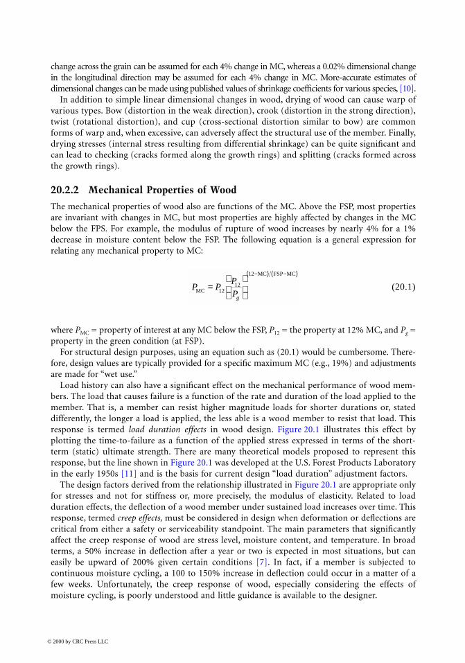
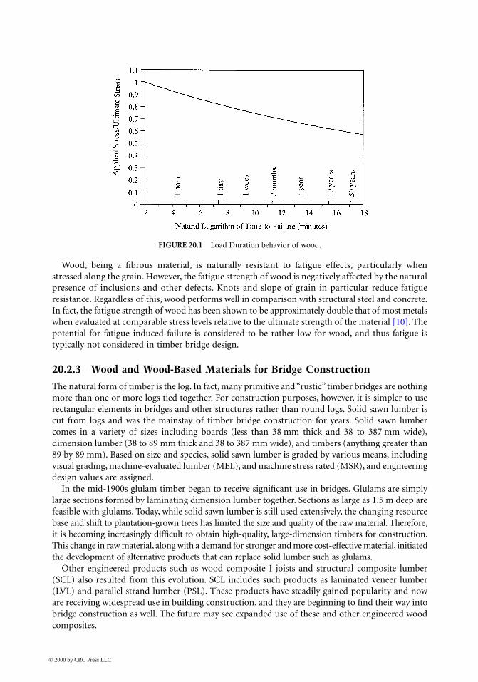
Load history can also have a significant effect on the mechanical performance of wood mem-bers. The load that causes failure is a function of the rate and duration of the load applied to themember. That is, a member can resist higher magnitude loads for shorter durations or, stateddifferently, the longer a load is applied, the less able is a wood member to resist that load. Thisresponse is termed load duration effects in wood design. Figure 20.1 illustrates this effect byplotting the time-to-failure as a function of the applied stress expressed in terms of the short-term (static) ultimate strength. There are many theoretical models proposed to represent thisresponse, but the line shown in Figure 20.1 was developed at the U.S. Forest Products Laboratoryin the early 1950s [11] and is the basis for current design “load duration” adjustment factors.
The design factors derived from the relationship illustrated in Figure 20.1 are appropriate onlyfor stresses and not for stiffness or, more precisely, the modulus of elasticity. Related to loadduration effects, the deflection of a wood member under sustained load increases over time. Thisresponse, termed creep effects, must be considered in design when deformation or deflections arecritical from either a safety or serviceability standpoint. The main parameters that significantlyaffect the creep response of wood are stress level, moisture content, and temperature. In broadterms, a 50% increase in deflection after a year or two is expected in most situations, but caneasily be upward of 200% given certain conditions [7]. In fact, if a member is subjected tocontinuous moisture cycling, a 100 to 150% increase in deflection could occur in a matter of afew weeks. Unfortunately, the creep response of wood, especially considering the effects ofmoisture cycling, is poorly understood and little guidance is available to the designer.
P PP
PgMC
MC FSP MC
=
−( ) −( )
1212
12
© 2000 by CRC Press LLC
Wood, being a fibrous material, is naturally resistant to fatigue effects, particularly whenstressed along the grain. However, the fatigue strength of wood is negatively affected by the naturalpresence of inclusions and other defects. Knots and slope of grain in particular reduce fatigueresistance. Regardless of this, wood performs well in comparison with structural steel and concrete.In fact, the fatigue strength of wood has been shown to be approximately double that of most metalswhen evaluated at comparable stress levels relative to the ultimate strength of the material [10]. Thepotential for fatigue-induced failure is considered to be rather low for wood, and thus fatigue istypically not considered in timber bridge design.
20.2.3 Wood and Wood-Based Materials for Bridge Construction
The natural form of timber is the log. In fact, many primitive and “rustic” timber bridges are nothingmore than one or more logs tied together. For construction purposes, however, it is simpler to userectangular elements in bridges and other structures rather than round logs. Solid sawn lumber iscut from logs and was the mainstay of timber bridge construction for years. Solid sawn lumbercomes in a variety of sizes including boards (less than 38 mm thick and 38 to 387 mm wide),dimension lumber (38 to 89 mm thick and 38 to 387 mm wide), and timbers (anything greater than89 by 89 mm). Based on size and species, solid sawn lumber is graded by various means, includingvisual grading, machine-evaluated lumber (MEL), and machine stress rated (MSR), and engineeringdesign values are assigned.
In the mid-1900s glulam timber began to receive significant use in bridges. Glulams are simplylarge sections formed by laminating dimension lumber together. Sections as large as 1.5 m deep arefeasible with glulams. Today, while solid sawn lumber is still used extensively, the changing resourcebase and shift to plantation-grown trees has limited the size and quality of the raw material. Therefore,it is becoming increasingly difficult to obtain high-quality, large-dimension timbers for construction.This change in raw material, along with a demand for stronger and more cost-effective material, initiatedthe development of alternative products that can replace solid lumber such as glulams.
Other engineered products such as wood composite I-joists and structural composite lumber(SCL) also resulted from this evolution. SCL includes such products as laminated veneer lumber(LVL) and parallel strand lumber (PSL). These products have steadily gained popularity and noware receiving widespread use in building construction, and they are beginning to find their way intobridge construction as well. The future may see expanded use of these and other engineered woodcomposites.
FIGURE 20.1 Load Duration behavior of wood.
© 2000 by CRC Press LLC

20.2.4 Preservation and Protection
As mentioned previously, one of the major advances in the 20th century allowing for continuedand expanded use of timber as a bridge material is pressure treatment. Two basic types of woodpreservatives are used: oil-type preservatives and waterborne preservatives. Oil-type preservativesinclude creosote, pentachlorophenol (or “penta”), and copper naphthenate. Creosote can be con-sidered the first effective wood preservative and has a long history of satisfactory performance.Creosote also offers protection against checking and splitting caused by changes in MC. Whilecreosote is a natural by-product from coal tar, penta is a synthetic pesticide. Penta is an effectivepreservative treatment; however, it is not effective against marine borers and is not used in marineenvironments. Penta is a “restricted-use” chemical, but wood treated with penta is not restricted.Copper naphthenate has received recent attention as a preservative treatment, primarily because itis considered an environmentally safe chemical while still giving satisfactory protection againstbiological attack. Its primary drawback is its high cost relative to other treatments. All these treat-ments generally leave the surface of the treated member with an oily and unfinishable surface.Furthermore, the member may “bleed” or leach preservative unless appropriate measures are taken.
Most timber bridge applications utilize oil-type preservatives for structural elements such asbeams, decks, piles, etc. They offer excellent protection against decay and biological attack, arenoncorrosive, and are relatively durable. Oil-type preservatives are not, however, recommended forbridge elements that may have frequent or repeated contact by humans or animals since they cancause skin irritations.
Waterborne preservatives have the advantage of leaving the surface of the treated material cleanand, after drying, able to be painted or stained. They also do not cause skin irritations and, therefore,can be used where repeated human and/or animal contact is expected. Waterborne preservativesuse formulations of inorganic arsenic compounds in a water solution. They do, however, leave thematerial with a light green, gray, or brownish color. But again, the surface can be later painted orstained. A wide variety of waterborne preservatives are available, but the most common includechromated copper arsenate (CCA), ammoniacal copper arsenate (ACA), and ammoniacal copperzinc arsenate (ACZA). Leaching of these chemicals is not a problem with these formulations sincethey each are strongly bound to the wood. CCA is commonly used to treat southern pine, ponderosapine, and red pine, all of which are relatively accepting of treatment. ACA and ACZA are used withspecies that are more difficult to treat, such as Douglas fir and larch. One potential drawback toCCA and ACA is a tendency to be corrosive to galvanized hardware. The extent to which this is aproblem is a function of the wood species, the specific preservative formulation, and service con-ditions. However, such corrosion seems not to be an issue for hot-dipped galvanized hardwaretypical in bridge applications.
Waterborne preservatives are used for timber bridges in applications where repeated or frequentcontact with humans or animals is expected. Such examples include handrails and decks for pedes-trian bridges. Additionally, waterborne preservatives are often used in marine applications wheremarine borer hazards are high.
Any time a material is altered due to chemical treatment its microlevel structure may be affected,thus affecting its mechanical properties. Oil-type preservatives do not react with the cellular struc-ture of the wood and, therefore, have little to no effect on the mechanical properties of the material.Waterborne preservatives do react, however, with the cell material, thus they can affect properties.Although this is an area of ongoing research, indications are that the only apparent effect ofwaterborne preservatives is to increase load duration effects, especially when heavy treatment isused for saltwater applications. Currently, no adjustments are recommended for design values ofpreservative treated wood vs. untreated materials.
In addition to preservative treatment, fire-retardant chemical treatment is also possible to inhibitcombustion of the material. These chemicals react with the cellular structure in wood and can causesignificant reductions in the mechanical properties of the material, including strength. Generally,
© 2000 by CRC Press LLC

fire retardants are not used in bridge applications. However, if fire-retardant-treated material is used,the designer should consult with the material producer or treater to obtain appropriate design values.
20.3 Types of Timber Bridges
Timber bridges come in a variety of forms, many having evolved from tradition. Most timber bridgesdesigned today, however, are the results of fairly recent developments and advances in the processingand treating of structural wood. The typical timber bridge is a single- or two-span structure. Single-span timber bridges are typically constructed with beams and a transverse deck or a slab-typelongitudinal deck. Two-span timber bridges are often beam with transverse decks. These and othercommon timber bridge types are presented in this section.
20.3.1 Superstructures
As with any bridge, the structural makeup can be divided into three basic components: the super-structure, the deck, and the substructure. Timber bridge superstructures can be further classifiedinto six basic types: beam superstructures, longitudinal deck (or slab) superstructures, trussedsuperstructures, trestles, suspension bridges, and glulam arches.
Beam SuperstructuresThe most basic form of a timber beam bridge is a log bridge. It is simply a bridge wherein logs arelaid alternately tip-to-butt and bound together. A transverse deck is then laid over the log beams.Obviously, spans of this type of bridge are limited to the size of logs available, but spans of 6 to 18m are reasonable. The service life of a log bridge is typically 10 to 20 years.
The sawn lumber beam bridge is another simple form. Typically, made of closely spaced 100to 200-mm-wide by 300 to 450-mm-deep beams, sawn lumber beams are usually used for clearspans up to 9 m. With the appropriate use of preservative treatments, sawn lumber bridges haveaverage service lives of approximately 40 years. A new alternative to sawn lumber is structuralcomposite lumber (SCL) bridges. Primarily, laminated veneer lumber (LVL) has been used inreplacement of solid sawn lumber in bridges. LVL can be effectively treated and can offer longservice as well.
Glulam timber beam bridges are perhaps the most prevalent forms of timber bridges today. Atypical glulam bridge configuration is illustrated in Figure 20.2. This popularity is primarily due tothe large variety of member sizes offered by glulams. Commonly used for clear spans ranging from6 to 24 m, glulam beam bridges have been used for clear spans up to 45 m. Transportation restrictionsrather than material limitations limit the length of beams, and, therefore, bridges. Since glulamtimber can be satisfactorily treated with preservatives, they offer a durable and long-lasting structuralelement. When designed such that field cutting, drilling, and boring are avoided, glulam bridgescan provide a service life of at least 50 years.
Longitudinal Deck SuperstructuresLongitudinal deck (or slab) superstructures are typically either glulam or nail-laminated timberplaced longitudinally to span between supports. A relatively new concept in longitudinal decksystems is the stress-laminated timber bridge, which is similar to the previous two forms exceptthat continuity in the system is developed through the use of high-strength steel tension rods. Inany case, the wide faces of the laminations are oriented vertically rather than horizontally as in atypical glulam beam. Figure 20.3 illustrates two types of glulam longitudinal decks: nonintercon-nected and interconnected. Since glulam timbers have depths typically less than the width of abridge, two or more segments must be used. When continuity is needed, shear dowels must be usedto provide interconnection between slabs. When continuity is not required, construction is simpli-fied. Figure 20.4 illustrates a typical stress-laminated section.
© 2000 by CRC Press LLC

Longitudinal deck systems are relatively simple and offer a relatively low profile, making theman excellent choice when vertical clearance is a consideration. Longitudinal decks are economicalchoices for clear spans up to approximately 10 m. Since the material can be effectively treated, theaverage service life of a longitudinal timber deck superstructure is at least 50 years. However, propermaintenance is required to assure an adequate level of prestress is maintained in stress-laminatedsystems.
Trussed SuperstructuresTimber trusses were used extensively for bridges in the first half of the 20th century. Many differenttruss configurations were used including king post, multiple king posts, Pratt, Howe, lattice, long,and bowstring trusses, to name a few. Clear spans of up to 75 m were possible. However, their
FIGURE 20.2 Glulam beam bridge with transverse deck. (Source: Ritter, M.A., EM7700-8, USDA Forest Service,Washington, D.C., 1990.)
© 2000 by CRC Press LLC

use has declined due primarily to high fabrication, erection, and maintenance costs. When timbertrusses are used today, it is typically driven more by aesthetics than by structural performanceor economics.
TrestlesAnother form of timber bridge which saw its peak usage in the first half of the 20th century wasthe trestle. A trestle is a series of short-span timber superstructures supported on a series of closelyspaced timber bents. During the railroad expansion during the early to mid 1900s, timber trestleswere a popular choice. However, their use has all but ceased because of high fabrication, erection,and maintenance costs.
Suspension BridgesA timber suspension bridge is simply a timber deck structure supported by steel cables. Timbertowers, in turn, support the steel suspension cables. Although there are examples of vehicular timbersuspension bridges, the more common use of this form of timber bridge is as a pedestrian bridge.They are typically used for relatively long clear spans, upward of 150 m. Since treated wood can beused throughout, 50-year service lives are expected.
FIGURE 20.3 Glulam longitudinal decks. (Source: Ritter, M.A., EM7700-8, USDA Forest Service, Washington, D.C.,1990.)
© 2000 by CRC Press LLC

Glued Laminated ArchesOne of the most picturesque forms of timber bridges is perhaps the glulam arch. Constructed fromsegmented circular or parabolic glulam arches, either two- or three-hinge arches are used. Theglulam arch bridge can have clear spans in excess of 60 m, and since glulam timber can be effectivelytreated, service lives of at least 50 years are well within reason. Although the relative first and life-cycle costs of arch bridges have become high, they are still a popular choice when aesthetics is anissue.
20.3.2 Timber Decks
The deck serves two primary purposes: (1) it is the part of the bridge structure that forms theroadway, and (2) it distributes the vehicular loads to the supporting elements of the superstructure.Four basic types of timber decks are sawn lumber planks, nailed laminated decks, glulam decks,and composite timber–concrete decks. The selection of a deck type depends mainly on the level ofload demand.
Lumber PlanksThe lumber plank deck is perhaps the simplest deck type. It is basically sawn lumber, typically 75to 150 mm thick and 250 to 300 mm wide, placed flatwise and attached to the supporting beamswith large spikes. Generally, the planks are laid transverse to the beams and traffic flow, but can beplaced longitudinally on cross beams as well. Lumber planks are only used for low-volume bridges.They are also of little use when protection of the supporting members is desired since water freelytravels between adjacent planks. Additionally, when a wearing surface such as asphalt is desired,lumber planks are not recommended since deflections between adjacent planks will result in crack-ing and deterioration of the wearing surface.
FIGURE 20.4 Stress laminated bridge. (Source: Ritter, M.A., EM7700-8, USDA Forest Service, Washington, D.C.,1990.)
© 2000 by CRC Press LLC

Nailed Laminated and Glulam DecksNailed laminated and glulam decks are essentially as described previously for longitudinal deck (orslab) superstructures. Nailed laminated systems are typically 38-mm-thick by 89- to 285-mm-deeplumber placed side by side and nailed or spiked together along its length. The entire deck is nailedtogether to act as a composite section and oriented such that the lumber is laid transverse to thebridge span across the main supporting beams, which are spaced from 0.6 to 1.8 m. Once a quitepopular deck system, its use has declined considerably in favor of glulam decks.
A glulam deck is a series of laminated panels, typically 130- to 220-mm thick by 0.9 to 1.5 mwide. The laminations of the glulam panel are oriented with their wide face vertically. Glulam deckscan be used with the panels in the transverse or longitudinal direction. They tend to be strongerand stiffer than nailed laminated systems and offer greater protection from moisture to the sup-porting members. Finally, although doweled glulam panels (see Figure 20.3) cost more to fabricate,they offer the greatest amount of continuity. With this continuity, thinner decks can be used, andimproved performance of the wearing surface is achieved due to reduced cracking and deterioration.
Composite Timber–Concrete DecksThe two basic types of composite timber–concrete deck systems are the T-section and the slab (seeFigure 20.5). The T-section is simply a timber stem, typically a glulam, with a concrete flange thatalso serves as the bridge deck. Shear dowels are plates that are driven into the top of the timberstem and develop the needed shear transfer. For a conventional single-span bridge, the concrete isproportioned such that it takes all the compression force while the timber resists the tension.Composite T-sections have seen some use in recent years; however, high fabrication costs havelimited their use.
Composite timber–concrete slabs were used considerably during the second quarter of the 20thcentury, but receive little use today. They are constructed with alternating depths of lumber typicallynailed laminated with a concrete slab poured directly on top of the timber slab. With a simple singlespan, the concrete again carries the compressive flexural stresses while the timber carries the flexuralstresses. Shear dowels or plates are driven into the timber slab to provide the required shear transferbetween the concrete and the timber.
20.3.3 Substructures
The substructure supports the bridge superstructure. Loads transferred from the superstructuresto the substructures are, in turn, transmitted to the supporting soil or rock. Specific types ofsubstructures that can be used are dependent on a number of variables, including bridge loads, soiland site conditions, etc. Although a timber bridge superstructure can be adapted to virtually anytype of substructure regardless of material, the following presentation is focused on timber sub-structures, specifically timber abutments and bents.
AbutmentsAbutments serve the dual purpose of supporting the bridge superstructure and the embankment.The simplest form of a timber abutment is a log, sawn lumber, or glulam placed directly on theembankment as a spread footing. However, this form is not satisfactory for any structurally demand-ing situation. A more common timber abutment is the timber pile abutment. Timber piles aredriven to provide the proper level of load-carrying capacity through either end bearing or friction.A backwall and wing walls are commonly added using solid sawn lumber to retain the embankment.A continuous cap beam is connected to the top of the piles on which the bridge superstructure issupported. A timber post abutment can be considered a hybrid between the spread footing and pileabutment. Timber posts are supported by a spread footing, and a backwall and wing walls are addedto retain the embankment. Pile abutments are required when soil conditions do not provide ade-quate support for a spread footing or when uplift is a design concern.
© 2000 by CRC Press LLC

BentsBents are support systems used for multispan bridges between the abutments. Essentially, timberbents are formed from a set of timber piles with lumber cross bracing. However, when the heightof the bent exceeds that available for a pile, frame bents are used. Frame bents were quite commonin the early days of the railroad, but, due to high cost of fabrication and maintenance, they are notused often for new bridges.
20.4 Basic Design Concepts
In this section, the basic design considerations and concepts for timber bridges are presented. Thediscussion should be considered an overview of the design process for timber bridges, not a replace-ment for specifications or standards.
20.4.1 Specifications and Standards
The design of timber bridge systems has evolved over time from what was tradition and essentiallya “master-builder” approach. Design manuals and specifications are available for use by engineersinvolved with or interested in timber bridge design. These include Timber Bridges: Design, Construc-tion, Inspection, and Maintenance [8], AASHTO LRFD Bridge Design Specifications [1], and AASHTO
FIGURE 20.5 Composite timber–concrete decks. (Source: Ritter, M.A., EM7700-8, USDA Forest Service, Washing-ton, D.C., 1990.)
© 2000 by CRC Press LLC

Standard Specifications for Highway Bridges [2]. The wood industry, through the American Forestand Paper Association (AF&PA), published design values for solid sawn lumber and glulam timberfor both allowable stress design [4] and load and resistance factor design [3] formats. Rather thanpresenting those aspects of bridge design common to all bridge types, the focus of the followingpresentation will be on those aspects specific to timber bridge design. Since bridge design is oftengoverned by AASHTO, focus will be on AASHTO specifications. However, AF&PA is the associationoverseeing the engineering design of wood, much like ACI is for concrete and AISC is for steel, andAF&PA-recommended design procedures will also be presented.
20.4.2 Design Values
Design values for wood are provided in a number of sources, including AF&PA specifications andAASHTO specifications. Although the design values published by these sources are based on thesame procedures per ASTM standards, specific values differ due to assumptions made for end-useconditions. The designer must take care to use the appropriate design values with their intendeddesign specification(s). For example, the design should not use AF&PA design values directly inAASHTO design procedures since AF&PA and AASHTO make different end-use assumptions.
AF&PA “Reference” Design ValuesThe AF&PA Manual for Engineered Wood Construction: Load and Resistance Factor Design [3] pro-vides nominal design values for visually and mechanically graded lumber, glulam timber, andconnections. These values include reference bending strength, Fb; reference tensile strength parallelto the grain, Ft; reference shear strength parallel to the grain, Fv; reference compressive strengthparallel and perpendicular to the grain, Fc and Fc⊥ , respectively; reference bearing strength parallelto the grain, Fg; and reference modulus of elasticity, E. These are appropriate for use with the LRFDprovisions.
Similarly, the Supplement to the NDS® provides tables of design values for visually graded andmachine stress rated lumber, and glulam timber for use in allowable stress design (ASD). The basicquantities are the same as with the LRFD, but are in the form of allowable stresses and are appropriatefor use with the ASD provisions of the NDS. Additionally, the NDS provides tabulated allowabledesign values for many types of mechanical connections.
One main difference between the ASD and LRFD design values, other than the ASD prescribingallowable stresses and the LRFD prescribing nominal strengths, is the treatment of duration of loadeffects. Allowable stresses (except compression perpendicular to the grain) are tabulated in the NDSand elsewhere for an assumed 10-year load duration in recognition of the duration of load effectdiscussed previously. The allowable compressive stress perpendicular to the grain is not adjustedsince a deformation definition of failure is used for this mode rather than fracture as in all othermodes; thus the adjustment has been assumed unnecessary. Similarly, the modulus of elasticity isnot adjusted to a 10-year duration since the adjustment is defined for strength, not stiffness. Forthe LRFD, short-term (i.e., 20 min) nominal strengths are tabulated for all strength values. In theLRFD, design strengths are reduced for longer-duration design loads based on the load combinationbeing considered. Conversely, in the NDS, allowable stresses are increased for shorter load durationsand decreased only for permanent (i.e., greater than 10 year) loading.
AASHTO-LRFD “Base” Design ValuesAASHTO-LRFD publishes its own design values which are different from those of the AF&PA LRFD.AASHTO publishes base bending strength, Fb0; base tensile strength parallel to the grain, Ft0; baseshear strength parallel to the grain, Fv0; base compressive strength parallel and perpendicular to thegrain, Fc0 and Fc⊥ , respectively; and base modulus of elasticity, E0. While the NDS publishes designvalues based on an assumed 10-year load duration and the AF&PA LRFD assumes a short-term(20-min) load duration, AASHTO publishes design values based on an assumed 2-month duration.
© 2000 by CRC Press LLC
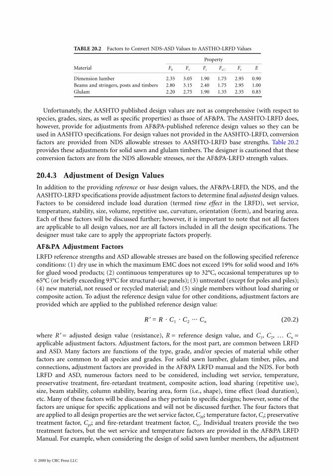
Unfortunately, the AASHTO published design values are not as comprehensive (with respect tospecies, grades, sizes, as well as specific properties) as thsoe of AF&PA. The AASHTO-LRFD does,however, provide for adjustments from AF&PA-published reference design values so they can beused in AASHTO specifications. For design values not provided in the AASHTO-LRFD, conversionfactors are provided from NDS allowable stresses to AASHTO-LRFD base strengths. Table 20.2provides these adjustments for solid sawn and glulam timbers. The designer is cautioned that theseconversion factors are from the NDS allowable stresses, not the AF&PA-LRFD strength values.
20.4.3 Adjustment of Design Values
In addition to the providing reference or base design values, the AF&PA-LRFD, the NDS, and theAASHTO-LRFD specifications provide adjustment factors to determine final adjusted design values.Factors to be considered include load duration (termed time effect in the LRFD), wet service,temperature, stability, size, volume, repetitive use, curvature, orientation (form), and bearing area.Each of these factors will be discussed further; however, it is important to note that not all factorsare applicable to all design values, nor are all factors included in all the design specifications. Thedesigner must take care to apply the appropriate factors properly.
AF&PA Adjustment FactorsLRFD reference strengths and ASD allowable stresses are based on the following specified referenceconditions: (1) dry use in which the maximum EMC does not exceed 19% for solid wood and 16%for glued wood products; (2) continuous temperatures up to 32°C, occasional temperatures up to65°C (or briefly exceeding 93°C for structural-use panels); (3) untreated (except for poles and piles);(4) new material, not reused or recycled material; and (5) single members without load sharing orcomposite action. To adjust the reference design value for other conditions, adjustment factors areprovided which are applied to the published reference design value:
R′ = R · C1 · C2 ··· Cn (20.2)
where R′ = adjusted design value (resistance), R = reference design value, and C1, C2, … Cn =applicable adjustment factors. Adjustment factors, for the most part, are common between LRFDand ASD. Many factors are functions of the type, grade, and/or species of material while otherfactors are common to all species and grades. For solid sawn lumber, glulam timber, piles, andconnections, adjustment factors are provided in the AF&PA LRFD manual and the NDS. For bothLRFD and ASD, numerous factors need to be considered, including wet service, temperature,preservative treatment, fire-retardant treatment, composite action, load sharing (repetitive use),size, beam stability, column stability, bearing area, form (i.e., shape), time effect (load duration),etc. Many of these factors will be discussed as they pertain to specific designs; however, some of thefactors are unique for specific applications and will not be discussed further. The four factors thatare applied to all design properties are the wet service factor, CM; temperature factor, Ct; preservativetreatment factor, Cpt; and fire-retardant treatment factor, Crt. Individual treaters provide the twotreatment factors, but the wet service and temperature factors are provided in the AF&PA LRFDManual. For example, when considering the design of solid sawn lumber members, the adjustment
TABLE 20.2 Factors to Convert NDS-ASD Values to AASTHO-LRFD Values
Property
Material Fb Fv Fc Fc⊥ Ft E
Dimension lumber 2.35 3.05 1.90 1.75 2.95 0.90Beams and stringers, posts and timbers 2.80 3.15 2.40 1.75 2.95 1.00Glulam 2.20 2.75 1.90 1.35 2.35 0.83
© 2000 by CRC Press LLC

values given in Table 20.3 for wet service, which is defined as the maximum EMC exceeding 19%,and Table 20.4 for temperature, which is applicable when continuous temperatures exceed 32°C,are applicable to all design values. Often with bridges, since they are essentially exposed structures,the MC will be expected to exceed 19%. Similarly, temperature may be a concern, but not ascommonly as MC.
Since, as discussed, LRFD and ASD handle time (duration of load) effects so differently and sinceduration of load effects are somewhat unique to wood design, it is appropriate to elaborate on ithere. Whether using ASD or LRFD, a wood structure is designed to resist all appropriate loadcombinations – unfactored combinations for ASD and factored combinations for LRFD. The timeeffects (LRFD) and load duration (ASD) factors are meant to recognize the fact that the failure ofwood is governed by a creep–rupture mechanism; that is, a wood member may fail at a load lessthan its short-term strength if that load is held for an extended period of time. In the LRFD, thetime effect factor, λ, is based on the load combination being considered. In ASD, the load durationfactor, CD, is given in terms of the assumed cumulative duration of the design load.
AASHTO-LRFD Adjustment FactorsAASHTO-LRFD base design values are based on the following specified reference conditions: (1)wet use in which the maximum EMC exceeds 19% for solid wood and 16% for glued wood products(this is opposite from the dry use assumed by AF&PA, since typical bridge use implies wet use); (2)continuous temperatures up to 32°C, occasional temperatures up to 65°C; (3) untreated (except forpoles and piles); (4) new material, not reused or recycled material; and (5) single members withoutload sharing or composite action. AASHTO has fewer adjustments available for the designer toconsider, primarily but not entirely due to the specific application. To adjust the base design valuefor other conditions, AASHTO-LRFD provides the following adjustment equation:
F = F0 · CF · CM · CD (20.3)
where F = adjusted design value (resistance), F0 = base design value, CF = size adjustment factor, CM =moisture content adjustment factor, CD = deck adjustment factor, and CS = stability adjustment factor.
The size factor is applicable only to bending and is essentially the same as that used by AF&PAfor solid sawn lumber and the same as the volume effect factor used by AF&PA for glulam timber.For solid sawn lumber and vertically laminated lumber, the size factor is defined as
(20.4)
TABLE 20.3 AF&PA LRFD Wet Service Adjustment Factors, CM
Size Adjusteda Fb Size Adjusteda Fc
Thickness ≤20 MPa >20 MPa Ft ≤12.4 MPa >12.4 MPa Fv Fc⊥ E, E05
≤90 mm 1.00 0.85 1.00 1.00 0.80 0.97 0.67 0.90>90 mm 1.00 1.00 1.00 0.91 0.91 1.00 0.67 1.00
a Reference value adjusted for size only.
TABLE 20.4 AF&PA-LRFD Temperature Adjustment Factors, Ct
Dry Use Wet Use
Sustained Temperature (°C) E, E05 All Other Prop. E, E05 All Other Prop.
32 < T ≤ 48 0.9 0.8 0.9 0.748 < T ≤ 65 0.9 0.7 0.9 0.5
CdF =
≤300
1 01 9
.
© 2000 by CRC Press LLC

where d = width (mm). The equation implies if lumber less than or equal to 300 mm in width is used,no adjustment is made. If, however, a width greater than 300 mm is used, a reduction in the publishedbase bending design value is required. For horizontally glulam timber, the “size” factor may moreappropriately be termed a volume factor (per the AF&PA). The size factor for glulam is given as
(20.5)
where d = width (mm), b = thickness (mm), L = span (mm), and a = 0.05 for southern pine and0.10 for all other species glulam. As with the previous size adjustment, if the dimensions of theglulam exceed 130 by 300 by 6400, then a reduction in the bending strength is required.
Unlike the size factor, the moisture factor is applicable to all published design values, not justbending strength. The moisture adjustment factor, CM, is again similar to that provided by AF&PA;however, it is embedded in the published base design values. Unless otherwise noted, CM should beassumed as unity. The only exception is when glulams are used and the moisture content is expectedto be less than 16%. An increase in the design values is then allowed per Table 20.5. A similar increaseis not allowed for lumber used at moisture contents less than 19% per AASHTO. This is a conser-vative approach in comparison with that of AF&PA.
The deck adjustment factor, CD, is again specific for the bending resistance, Fb, of 50- to 100-mm-wide lumber used in stress-laminated and mechanically (nail or spike) laminated deck systems. Forstress-laminated decks, the bending strength can be increased by a factor of CD = 1.30 for selectstructural grade lumber, and CD = 1.5 for No. 1 and No. 2 grade. For mechanically laminated decks,the bending strength of all grades can be increased by a factor of CD = 1.15.
Since, as discussed, AF&PA LRFD and ASD handle time (duration of load) effects so differentlyand since duration of load effects are somewhat unique to wood design, it is appropriate to elaborateon it here and understand how time effects are accounted for by AASHTO-LRFD. Implicit in theAASHTO-LRFD Specification, λ = 0.8 is assumed for vehicle live loads. The published base designvalues are reduced by a factor of 0.80 to account for time effects. For strength load combinationIV, however, a reduction of 75% is required. This load combination is for dead load only. Therationale behind this reduction is found in the AF&PA-LRFD time effects factors. For live-load-governed load combinations, AF&PA requires λ = 0.8; and for dead load only, λ = 0.6 is used. Theratio of the dead-load time effect factor to the live-load time effect factor is 0.6/0.8 = 0.75.
20.4.4 Beam Design
The focus of the remaining discussion will be on the design provisions specified in the AASHTO-LRFD for wood members. The design of wood beams follows traditional beam theory. The flex-ural strength of a beam is generally the primary concern in a beam design, but consideration ofother factors such as horizontal shear, bearing, and deflection are also crucial for a successful design.
Moment CapacityIn terms of moment, the AASHTO-LRFD design factored resistance, Mr, is given by
(20.6)
TABLE 20.5 AASHTO-LRFD Moisture Content Adjustment Factors, CM, for Glulam
Property
Fb Fv Fc Fcp Ft E
1.25 1.15 1.35 1.90 1.25 1.20
Cd b LF
a
=
≤300 130 64001 0.
M M F SCr b n b b s= =φ φ
© 2000 by CRC Press LLC

where φb = resistance factor for bending = 0.85, Mn = nominal adjusted moment resistance, Fb =adjusted bending strength, S = section modulus, and Cs = beam stability factor.
The beam stability factor, Cs, is only used when considering strong axis bending since a beamoriented about its weak axis is not susceptible to lateral instability. Additionally, the beam stabilityfactor need not exceed the value of the size effects factor. The beam stability factor is taken as 1.0for members with continuous lateral bracing; otherwise Cs is calculated from
(20.7)
where
for visually graded solid sawn lumber (20.8)
and
for mechanically graded lumber and glulams (20.9)
where E = modulus of elasticity, b = net thickness, d = net width, Le = effective length, and Fb =adjusted bending strength. The effective length, Le, accounts for both the lateral motion and torsionalphenomena and is given in the AASHTO-LRFD specification for specific unbraced lengths, Lu,defined as the distance between points of lateral and rotations support. For Lu/d < 7, the effectiveunbraced length, Le = 2.06Lu; for 7 ≤ Lu/d ≤ 14.3, Le = 1.63Lu + 3d; and for lu/d > 14.3, Le = 1.84Lu.
While the basic adjustment factor for beam stability is quite similar between AASHTO andAF&PA, the consideration of beam stability and size effects combined differs significantly from theapproach used by AF&PA. For solid sawn lumber, AF&PA requires both the size factor and the beamstability factor apply. For glulams, AF&PA prescribes the lesser of the volume factor or the stabilityfactor be used. AASHTO compared with AF&PA is potentially nonconservative with respect tolumber elements and conservative with respect to glulam elements.
Shear CapacitySimilar to bending, the basic design equation for the factored shear resistance, Vr, is given by
(20.10)
where φv = resistance factor for shear = 0.75, Vn = nominal adjusted shear resistance, Fv = adjustedshear strength, and b and d = thickness and width, respectively. Obviously, the last expression inEq. (20.10) assumes a rectagular section, the nominal shear resistance could be determined fromthe relationship
(20.11)
where I = monent of inertia and Q = statical moment of an area about the neutral axis.In timber bridges, notches are often made at the support to allow for vertical clearances and
tolerances as illustrated in Figure 20.6; however, stress concentrations resulting from these notches
CA A A
Cs F= + − +( ) − ≤11 9
13 61 0 95
2
. . .
AEB
L dFe b
= 0 438 2.
AEb
L dFe b
= 0 609 2.
V VF bd
r v n vv= =φ φ1 5.
VF Ib
Qnv=
© 2000 by CRC Press LLC
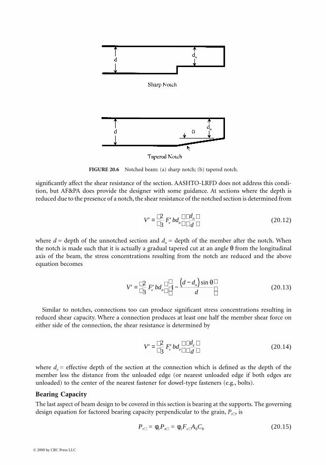
significantly affect the shear resistance of the section. AASHTO-LRFD does not address this condi-tion, but AF&PA does provide the designer with some guidance. At sections where the depth isreduced due to the presence of a notch, the shear resistance of the notched section is determined from
(20.12)
where d = depth of the unnotched section and dn = depth of the member after the notch. Whenthe notch is made such that it is actually a gradual tapered cut at an angle θ from the longitudinalaxis of the beam, the stress concentrations resulting from the notch are reduced and the aboveequation becomes
(20.13)
Similar to notches, connections too can produce significant stress concentrations resulting inreduced shear capacity. Where a connection produces at least one half the member shear force oneither side of the connection, the shear resistance is determined by
(20.14)
where de = effective depth of the section at the connection which is defined as the depth of themember less the distance from the unloaded edge (or nearest unloaded edge if both edges areunloaded) to the center of the nearest fastener for dowel-type fasteners (e.g., bolts).
Bearing CapacityThe last aspect of beam design to be covered in this section is bearing at the supports. The governingdesign equation for factored bearing capacity perpendicular to the grain, Pr⊥ , is
Pr⊥ = φcPn⊥ = φcFc⊥ AbCb (20.15)
FIGURE 20.6 Notched beam: (a) sharp notch; (b) tapered notch.
′ = ′
V F bd
d
dv nn2
3
′ = ′
−
−( )
V F bd
d d
dv nn2
31
sin θ
′ = ′
V F bd
d
dv ee2
3
© 2000 by CRC Press LLC
where φc = resistance factor for compression = 0.90, Pnp = nominal adjusted compression resistanceperpendicular to the grain, Fcp = adjusted compression strength perpendicular to the grain, Ab =bearing area, and Cb = bearing factor.
The bearing area factor, Cb, allows an increase in the compression strength when the bearinglength along the grain, lb, is no more than 150 mm along the length of the member, is at least 75 mmfrom the end of the member, and is not in a region of high flexural stress. The bearing factor Cb isgiven by AF&PA as
Cb = (lb + 9.5)/lb (20.16)
where lb is in mm. This equation is the basis for the adjustment factors presented in the AASHTO-LRFD. For example, if a bearing length of 50 mm is used, the bearing strength can be increased bya factor of (50 + 9.5)/50 = 1.19.
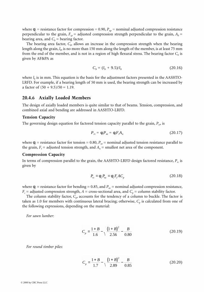
20.4.6 Axially Loaded Members
The design of axially loaded members is quite similar to that of beams. Tension, compression, andcombined axial and bending are addressed in AASHTO-LRFD.
Tension CapacityThe governing design equation for factored tension capacity parallel to the grain, Prt, is
Prt = φtPnt = φtFtAn (20.17)
where φt = resistance factor for tension = 0.80, Pnt = nominal adjusted tension resistance parallel tothe grain, Ft = adjusted tension strength, and An = smallest net area of the component.
Compression CapacityIn terms of compression parallel to the grain, the AASHTO-LRFD design factored resistance, Prc isgiven by
(20.18)
where φc = resistance factor for bending = 0.85, and Pnc = nominal adjusted compression resistance,Fc = adjusted compression strength, A = cross-sectional area, and Cp = column stability factor.
The column stability factor, Cp, accounts for the tendency of a column to buckle. The factor istaken as 1.0 for members with continuous lateral bracing; otherwise, Cp is calculated from one ofthe following expressions, depending on the material:
For sawn lumber:
(20.19)
For round timber piles:
(20.20)
P P F ACrc c nc c c p= =φ φ
CB B B
p = + − +( ) −11 6
1
2 56 0 80
2
. . .
CB B B
p = + − +( ) −11 7
1
2 89 0 85
2
. . .
© 2000 by CRC Press LLC
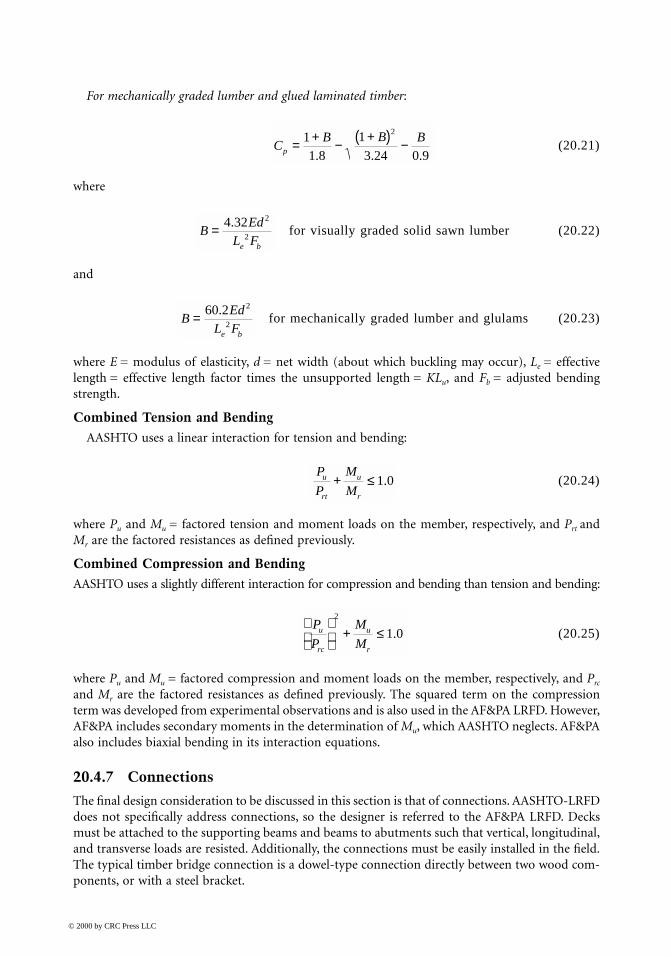
For mechanically graded lumber and glued laminated timber:
(20.21)
where
for visually graded solid sawn lumber (20.22)
and
for mechanically graded lumber and glulams (20.23)
where E = modulus of elasticity, d = net width (about which buckling may occur), Le = effectivelength = effective length factor times the unsupported length = KLu, and Fb = adjusted bendingstrength.
Combined Tension and BendingAASHTO uses a linear interaction for tension and bending:
(20.24)
where Pu and Mu = factored tension and moment loads on the member, respectively, and Prt andMr are the factored resistances as defined previously.
Combined Compression and BendingAASHTO uses a slightly different interaction for compression and bending than tension and bending:
(20.25)
where Pu and Mu = factored compression and moment loads on the member, respectively, and Prc
and Mr are the factored resistances as defined previously. The squared term on the compressionterm was developed from experimental observations and is also used in the AF&PA LRFD. However,AF&PA includes secondary moments in the determination of Mu, which AASHTO neglects. AF&PAalso includes biaxial bending in its interaction equations.
20.4.7 Connections
The final design consideration to be discussed in this section is that of connections. AASHTO-LRFDdoes not specifically address connections, so the designer is referred to the AF&PA LRFD. Decksmust be attached to the supporting beams and beams to abutments such that vertical, longitudinal,and transverse loads are resisted. Additionally, the connections must be easily installed in the field.The typical timber bridge connection is a dowel-type connection directly between two wood com-ponents, or with a steel bracket.
CB B B
p = + − +( ) −11 8
1
3 24 0 9
2
. . .
BEd
L Fe b
= 4 32 2
2
.
BEd
L Fe b
= 60 2 2
2
.
P
P
M
Mu
rt
u
r
+ ≤1 0.
P
P
M
Mu
rc
u
r
+ ≤
2
1 0.
© 2000 by CRC Press LLC

The design of fasteners and connections for wood has undergone significant changes in recentyears. Typical fastener and connection details for wood include nails, staples, screws, lag screws,dowels, and bolts. Additionally, split rings, shear plates, truss plate connectors, joist hangers, andmany other types of connectors are available to the designer. The general LRFD design checkingequation for connections is given as follows:
Zu ≤ λφzZ′ (20.26)
where Zu = connection force due to factored loads, λ = applicable time effect factor, φz = resistancefactor for connections = 0.65, and Z′ = connection resistance adjusted by the appropriate adjustmentfactors.
It should be noted that, for connections, the moisture adjustment is based on both in-servicecondition and on conditions at the time of fabrication; that is, if a connection is fabricated in thewet condition but is to be used in service under a dry condition, the wet condition should be usedfor design purposes due to potential drying stresses which may occur. It should be noted that CM
does not account for corrosion of metal components in a connection. Other adjustments specificto connection type (e.g., end grain factor, Ceg; group action factor, Cg; geometry factor, C∆; pene-tration depth factor, Cd; toe-nail factor, Ctn; etc.) will be discussed with their specific use. It shouldalso be noted that when failure of a connection is controlled by a nonwood element (e.g., fractureof a bolt), then the time-effects factor is taken as unity since time effects are specific to wood andnot applicable to nonwood components.
In both LRFD and ASD, tables of reference resistances (LRFD) and allowable loads (ASD) areavailable which significantly reduce the tedious calculations required for a simple connection design.In this section, the basic design equations and calculation procedures are presented, but designtables are not provided herein.
The design of general dowel-type connections (i.e., nails, spikes, screws, bolts, etc.) for lateralloading are currently based on possible yield modes. Based on these possible yield modes, lateralresistances are determined for the various dowel-type connections. Specific equations are presentedin the following sections for nails and spikes, screws, bolts, and lag screws. In general, however, thedowel bearing strength, Fe, is required to determine the lateral resistance of a dowel-type connection.Obviously, this property is a function of the orientation of the applied load to the grain, and valuesof Fe are available for parallel to the grain, Fe||, and perpendicular to the grain, Fe⊥ . The dowel bearingstrength or other angles to the grain, Feθ, is determined by
(20.27)
where θ = angle of load with respect to a direction parallel to the grain.
Nails, Spikes, and ScrewsNails, spikes, and screws are perhaps the most commonly used fastener in wood construction. Nailsare generally used when loads are light such as in the construction of diaphragms and shear walls;however, they are susceptible to working loose under vibration or withdrawal loads. Common wirenails and spikes are quite similar, except that spikes have larger diameters than nails. Both a 12d(i.e., 12-penny) nail and spike are 88.9 mm in length; however, a 12d nail has a diameter of 3.76 mmwhile a spike has a diameter of 4.88 mm. Many types of nails have been developed to provide betterwithdrawal resistance, such as deformed shank and coated nails. Nonetheless, nails and spikes shouldbe designed to carry laterally applied load and not withdrawal. Screws behave in a similar mannerto nails and spikes, but also provide some withdrawal resistance.
FF F
F Fee e
e eθ θ θ
=+
⊥
⊥
||
|| sin cos2 2
© 2000 by CRC Press LLC
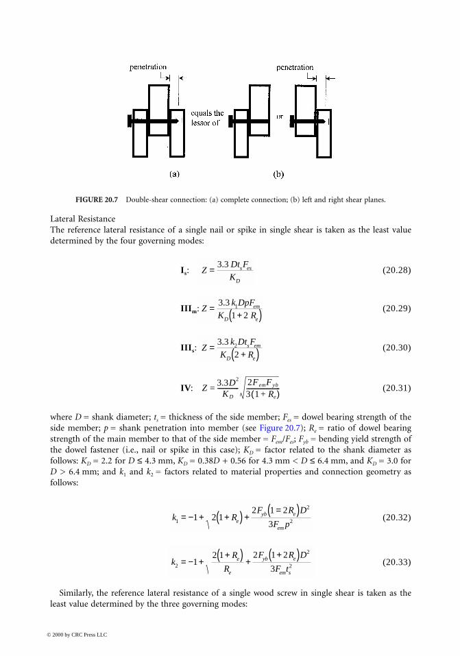
Lateral ResistanceThe reference lateral resistance of a single nail or spike in single shear is taken as the least valuedetermined by the four governing modes:
Is: (20.28)
IIIm: (20.29)
IIIs: (20.30)
IV: (20.31)
where D = shank diameter; ts = thickness of the side member; Fes = dowel bearing strength of theside member; p = shank penetration into member (see Figure 20.7); Re = ratio of dowel bearingstrength of the main member to that of the side member = Fem/Fes; Fyb = bending yield strength ofthe dowel fastener (i.e., nail or spike in this case); KD = factor related to the shank diameter asfollows: KD = 2.2 for D ≤ 4.3 mm, KD = 0.38D + 0.56 for 4.3 mm < D ≤ 6.4 mm, and KD = 3.0 forD > 6.4 mm; and k1 and k2 = factors related to material properties and connection geometry asfollows:
(20.32)
(20.33)
Similarly, the reference lateral resistance of a single wood screw in single shear is taken as theleast value determined by the three governing modes:
FIGURE 20.7 Double-shear connection: (a) complete connection; (b) left and right shear planes.
ZDt F
Ks es
D
=3 3.
Zk DpF
K Rem
D e
=+( )
3 3
1 21.
Zk Dt F
K Rs em
D e
=+( )
3 3
22.
Z3.3D2
KD
--------------2FemFyb
3 1 Re+( )----------------------=
k RF R D
F peyb e
em1
2
21 2 12 1 2
3= − + +( ) +
=( )
kR
R
F R D
F te
e
yb e
em s2
2
212 1 2 1 2
3= − +
+( ) ++( )
© 2000 by CRC Press LLC
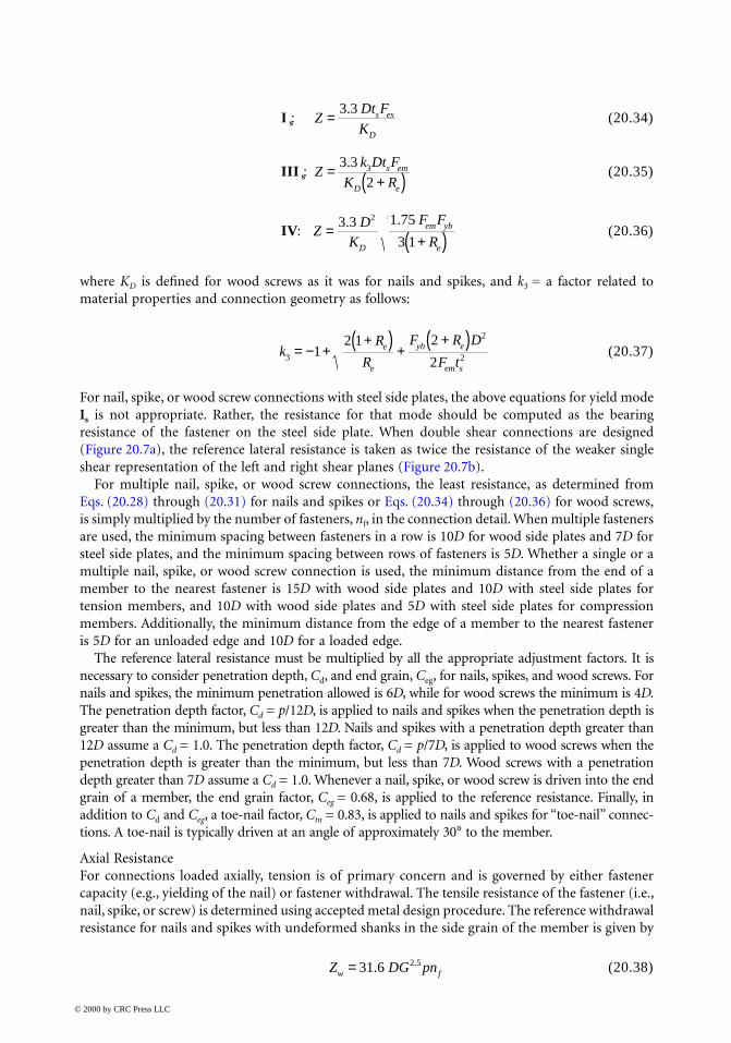
I s: (20.34)
III s: (20.35)
IV: (20.36)
where KD is defined for wood screws as it was for nails and spikes, and k3 = a factor related tomaterial properties and connection geometry as follows:
(20.37)
For nail, spike, or wood screw connections with steel side plates, the above equations for yield modeIs is not appropriate. Rather, the resistance for that mode should be computed as the bearingresistance of the fastener on the steel side plate. When double shear connections are designed(Figure 20.7a), the reference lateral resistance is taken as twice the resistance of the weaker singleshear representation of the left and right shear planes (Figure 20.7b).
For multiple nail, spike, or wood screw connections, the least resistance, as determined fromEqs. (20.28) through (20.31) for nails and spikes or Eqs. (20.34) through (20.36) for wood screws,is simply multiplied by the number of fasteners, nf, in the connection detail. When multiple fastenersare used, the minimum spacing between fasteners in a row is 10D for wood side plates and 7D forsteel side plates, and the minimum spacing between rows of fasteners is 5D. Whether a single or amultiple nail, spike, or wood screw connection is used, the minimum distance from the end of amember to the nearest fastener is 15D with wood side plates and 10D with steel side plates fortension members, and 10D with wood side plates and 5D with steel side plates for compressionmembers. Additionally, the minimum distance from the edge of a member to the nearest fasteneris 5D for an unloaded edge and 10D for a loaded edge.
The reference lateral resistance must be multiplied by all the appropriate adjustment factors. It isnecessary to consider penetration depth, Cd, and end grain, Ceg, for nails, spikes, and wood screws. Fornails and spikes, the minimum penetration allowed is 6D, while for wood screws the minimum is 4D.The penetration depth factor, Cd = p/12D, is applied to nails and spikes when the penetration depth isgreater than the minimum, but less than 12D. Nails and spikes with a penetration depth greater than12D assume a Cd = 1.0. The penetration depth factor, Cd = p/7D, is applied to wood screws when thepenetration depth is greater than the minimum, but less than 7D. Wood screws with a penetrationdepth greater than 7D assume a Cd = 1.0. Whenever a nail, spike, or wood screw is driven into the endgrain of a member, the end grain factor, Ceg = 0.68, is applied to the reference resistance. Finally, inaddition to Cd and Ceg, a toe-nail factor, Ctn = 0.83, is applied to nails and spikes for “toe-nail” connec-tions. A toe-nail is typically driven at an angle of approximately 30° to the member.
Axial ResistanceFor connections loaded axially, tension is of primary concern and is governed by either fastenercapacity (e.g., yielding of the nail) or fastener withdrawal. The tensile resistance of the fastener (i.e.,nail, spike, or screw) is determined using accepted metal design procedure. The reference withdrawalresistance for nails and spikes with undeformed shanks in the side grain of the member is given by
(20.38)
ZDt F
Ks es
D
=3 3.
Zk Dt F
K Rs em
D e
=+( )
3 3
23.
ZD
K
F F
RD
em yb
e
=+( )
3 3 1 75
3 1
2. .
kR
R
F R D
F te
e
yb e
em s3
2
212 1 2
2= − +
+( ) ++( )
Z DG pnw f= 31 6 2 5. .
© 2000 by CRC Press LLC

where Zw = reference withdrawal resistance in newtons and G = specific gravity of the wood. Fornails and spikes with deformed shanks, design values are determined from tests and supplied byfastener manufactures, or Eq. (20.38) can be used conservatively with D = least shank diameter. Forwood screws in the side grain,
(20.39)
A minimum wood screw depth of penetration of at least 25 mm or one half the nominal length ofthe screw is required for Eq. (20.39) to be applicable. No withdrawal resistance is assumed for nails,spikes, or wood screws used in end grain applications.
The end grain adjustment factor, Ceg, and the toe-nail adjustment factor, Ctn, as defined for lateralresistance, are applicable to the withdrawal resistances. The penetration factor is not applicable,however, to withdrawal resistances.
Combined Load ResistanceThe adequacy of nail, spike, and wood screw connections under combined axial tension and lateralloading is checked using the following interaction equation:
(20.40)
where α = angle between the applied load and the wood surface (i.e., 0° = lateral load and 90° =withdrawal/tension).
Bolts, Lag Screws, and DowelsBolts, lag screws, and dowels are commonly used to connect larger-dimension members where largerconnection capacities are required. The provisions presented here are valid for bolts, lag screws,and dowels with diameters in the range of 6.3 mm ≤ D ≤ 25.4 mm.
Lateral ResistanceThe reference lateral resistance of a bolt or dowel in single shear is taken as the least value determinedby the six governing modes:
Im: (20.41)
Is: (20.42)
II: (20.43)
IIIm: (20.44)
IIIs: (20.45)
IV: (20.46)
Z DG pnw f= 65 3 2.
Z
Z
Z
Zu
z
u
z w
cos sin.
αλφ
αλφ′
+′
≤ 1 0
ZDt F
Km em=
0 83.
θ
ZDt F
Ks es=
0 83.
θ
Z0.93k1DFes
Kθ----------------------------=
Zk Dt F
K Rm em
e
=+( )
1 04
1 22.
θ
Zk Dt F
K Rs em
e
=+( )
1 04
23.
θ
ZD
K
F F
Rem yb
e
=+( )
1 04 2
3 1
2.
θ
© 2000 by CRC Press LLC

where D = shank diameter; tm and ts = thickness of the main and side member, respectively; Fem =Fes = dowel bearing strength of the main and side member, respectively; Re = ratio of dowel bearingstrength of the main member to that of the side member = Fem/Fes; Fyb = bending yield strength ofthe dowel fastener (i.e., nail or spike in this case); Kθ = factor related to the angle between the loadand the main axis (parallel to the grain) of the member = 1 + 0.25(θ/90); and k1, k2, and k3 = factorsrelated to material properties and connection geometry as follows:
(20.47)
(20.48)
(20.49)
where Rt = ratio of the thickness of the main member to that of the side member = tm/ts.The reference lateral resistance of a bolt or dowel in double shear is taken as the least value
determined by the four governing modes:
Im: (20.50)
Is: (20.51)
IIIs: (20.52)
IV: (20.53)
where k3 is defined by Eq. (20.49)Similarly, the reference lateral resistance of a single lag screw in single shear is taken as the least
value determined by the three governing modes:
Is : (20.54)
IIIs : (20.55)
IV: (20.56)
where k4 = a factor related to material properties and connection geometry as follows:
kR R R R R R R R
Re e t t t e e t
e1
2 2 2 32 1 1
1=
+ + +( ) + − +( )+
k RF R D
F teyb e
em m2
2
21 2 12 1 2
3= − + +( ) +
+( )
kR
R
F R D
F te
e
yb e
em s3
2
212 1 2 1 2
3= − +
+( ) ++( )
ZDt F
Km em=
0 83.
θ
ZDt F
Ks es=
1 66.
θ
Zk Dt F
K Rs em
e
=+( )
2 08
23.
θ
ZD
K
F F
Rem yb
e
=+( )
2 08 2
3 1
2.
θ
ZDt F
Ks es=
0 83.
θ
Zk Dt F
K Rr s em
e
=+( )
1 19
1
.
θ
ZD
K
F F
Rem yb
e
=+( )
1 11 1 75
3 1
2. .
θ
© 2000 by CRC Press LLC

(20.57)
When double shear lag screw connections are designed, the reference lateral resistance is taken astwice the resistance of the weaker single shear representation of the left and right shear planes aswas described for nail and wood screw connections.
Wood members are often connected to nonwood members with bolt and lag screw connections(e.g., wood to concrete, masonry, or steel). For connections with concrete or masonry main mem-bers, the dowel bear strength, Fem, for the concrete or masonry can be assumed the same as thewood side members with an effective thickness of twice the thickness of the wood side member.For connections with steel side plates, the equations for yield modes Is and Im are not appropriate.Rather, the resistance for that mode should be computed as the bearing resistance of the fasteneron the steel side plate.
For multiple bolt, lag screw, and dowel connections, the least resistance is simply multiplied bythe number of fasteners, nf, in the connection detail. When multiple fasteners are used, the minimumspacings, edge distances, and end distances are dependent on the direction of loading. When loadingis primarily parallel to the grain, the minimum spacing between fasteners in a row (parallel to thegrain) is 4D, and the minimum spacing between rows (perpendicular to the grain) of fasteners is1.5D but not greater than 127 mm.* The minimum edge distance is dependent on lm = length ofthe fastener in the main member for spacing in the main member or total fastener length in theside members for side member spacing relative to the diameter of the fastener. For shorter fasteners(lm/D ≤ 6), the minimum edge distance is 1.5D, while for longer fasteners (lm/D > 6), the minimumedge distance is the greater of 5D or one half the spacing between rows (perpendicular to the grain).The minimum end distance is 7D for tension members and 4D for compression members. Whenloading is primarily perpendicular to the grain, the minimum spacing within a row (perpendicularto the grain) is typically limited by the attached member but not to exceed 127 mm,* and theminimum spacing between rows (parallel to the grain) is dependent on lm. For shorter fastenerlengths (lm/D ≤ 2), the spacing between rows is limited to 2D; for medium fastener lengths (2 <lm/D < 6), the spacing between rows is limited to (5lm +10D)/8; and for longer fastener lengths (lm/D≥ 6), the spacing is limited to 5D; but never should the spacing exceed than 127 mm.* The minimumedge distance is 4D for loaded edges and 1.5D for unloaded edges. Finally, the minimum end distancefor members loaded primarily perpendicular to the grain is 4D.
The reference lateral resistance must be multiplied by all appropriate adjustment factors. It isnecessary to consider group action, Cg, and geometry, C∆ for bolts, lag screws, and dowels. Inaddition, penetration depth, Cd, and end grain, Ceg, need to be considered for lag screws. The groupaction factor accounts for load distribution between bolts, lag screw, or dowels when one or morerows of fasteners are used and is defined by
(20.58)
where nf = number of fasteners in the connection, nr = number of rows in the connection, and ai =effective number of fasteners in row i due to load distribution in a row and is defined by
(20.59)
*The limit of 127 mm can be violated if allowances are made for dimensional changes of the wood.
kR
R
F R D
F te
e
yb e
em s4
2
212 1 2
2= − +
+( ) ++( )
Cn
agf
i
i
nr
==∑1
1
aR
m
m m
R m m miEA
n
EAn n
i
i i= +
−
−( )+( ) +( ) − +
1
1
1
1 1 1
2
2
© 2000 by CRC Press LLC

where
(20.60a)
(20.60b)
and where γ = load/slip modulus for a single fastener; s = spacing of fasteners within a row; (EA)m
and (EA)s = axial stiffness of the main and side member, respectively; REA = ratio of the smaller of(EA)m and (EA)s to the larger of (EA)m and (EA)s. The load/slip modulus, γ, is either determinedfrom testing or assumed as γ = 0.246D1.5 kN/mm for bolts, lag screws, or dowels in wood-to-woodconnections or γ = 0.369D1.5 kN/mm for bolts, lag screws, or dowels in wood-to-steel connections.
The geometry factor, C∆, is used to adjust for connections in which either end distances and/orspacing within a row does not meet the limitations outlined previously. Defining a = actual mini-mum end distance, amin = minimum end distance as specified previously, s = actual spacing offasteners within a row, and smin = minimum spacing as specified previously, the lesser of the followinggeometry factors are used to reduce the adjusted resistance of the connection:
1. End distance: for, a ≥ amin, C∆ = 1.0for amin/2 ≤ a < amin, C∆ = a/amin
2. Spacing: for, s ≥ smin, C∆ = 1.0for 3D ≤ s < smin, C∆ = s/smin
In addition to group action and geometry, the penetration depth factor, Cd, and end grain factor,Ceg, are applicable to lag screws (not bolts and dowels). The penetration of a lag screw, includingthe shank and thread less the threaded tip, is required to be at least 4D. For penetrations of at least4D but not more than 8D, the connection resistance is multiplied by Cd = p/8D, where p = depthof penetration. For penetrations of at least 8D, Cd = 1.0. The end grain factor, Ceg, is applied whena lag screw is driven in the end grain of a member and is given as Ceg = 0.67.
Axial ResistanceAgain, the tensile resistance of the fastener (i.e., bolt, lag screw, or dowel) is determined usingaccepted metal design procedure. Withdrawal resistance is only appropriate for lag screws sincebolts and dowels are “through-member” fasteners. For the purposes of lag screw withdrawal, thepenetration depth, p, is assumed as the threaded length of the screw less the tip length, and theminimum penetration depth for withdrawal is the lesser of 25 mm or one half the threaded length.The reference withdrawal resistance of a lag screw connection is then given by
(20.61)
where Zw = reference withdrawal resistance in newtons and G = specific gravity of the wood.The end grain adjustment factor, Ceg, is applicable to the withdrawal resistance of lag screws and
is defined as Ceg = 0.75.
Combined Load ResistanceThe resistance of a bolt, dowel, or lag screw connection to combined axial and lateral load is given by
(20.62)
where = adjusted resistance at an angle and α = angle between the applied load and the woodsurface (i.e., 0° = lateral load and 90° = withdrawal/tension).
m u u= − −2 1
us
EA EAm s
= + ( ) + ( )
1
21 1γ
Z D G pnw f= 92 6 0 75 1 5. . .
′ = ′ ′′ + ′
ZZ Z
Z Zw
wα α αsin cos2 2
′Zα
© 2000 by CRC Press LLC

References
1. American Association of State Highway and Transportation Officials (AASHTO), AASHTO LRFDBridge Design Specifications, AASHTO, Washington, D.C., 1994.
2. American Association of State Highway and Transportation Officials (AASHTO), Standard Speci-fications for Highway Bridges, 16th ed. AASHTO, Washington, D.C., 1996.
3. American Forest and Paper Association (AF&PA), Manual of Wood Construction: Load and Resis-tance Factor Design, AF&PA, Washington, D.C., 1996.
4. American Forest and Paper Association (AF&PA), National Design Specification for Wood Construc-tion and Supplement, AF&PA, Washington, D.C., 1997.
5. Bodig, J. and Jayne, B., Mechanics of Wood and Wood Composites, Van Nostrand Reinhold, NewYork, 1982.
6. Freas, A.D., Wood properties, in Wood Engineering and Construction Handbook, 2nd ed., K.F.Faherty and T.G. Williamson, Eds., McGraw Hill, New York, 1995.
7. Fridley, K.J., Designing for creep in wood structures, For. Prod. J., 42(3):23–28, 1992.8. Ritter, M.A., Timber Bridges: Design, Construction, Inspection, and Maintenance, EM 7700-8,
USDA, Forest Service, Washington, D.C., 1990.9. Ritter, M.A. and Ebeling, D.W., Miscellaneous wood structures, in Wood Engineering and Construc-
tion Handbook, 2nd ed., K.F. Faherty and T.G. Williamson, Eds. McGraw-Hill, New York, 1995.10. U.S. Department of Agriculture (USDA), Wood Handbook: Wood as an Engineering Material,
Agriculture Handbook 72, Forest Products Laboratory, USDA, Madison, WI, 1987.11. Wood, L.W., Relation of Strength of Wood to Duration of Load, USDA Forest Service Report No.
1916, Forest Products Laboratory, USDA, Madison, WI, 1951.
Further Reading
1. American Institute of Timber Construction (AITC), Glulam Bridge Systems, AITC, Englewood,CO, 1988.
2. American Institute of Timber Construction (AITC), AITC 117-93, Design Standard Specificationsfor Structural Glued Laminated Timber of Softwood Species, 1993. AITC, Englewood, CO,1993.
3. American Institute of Timber Construction (AITC), Timber Construction Manual, Wiley Inter-Science, New York, 1994.
4. Western Wood Products Association (WWPA), Western Wood Use Book, 4th ed. WWPA, Portland,OR, 1996.
5. Wipf, T.J., Klaiber, F.W., and Sanders, W.W., Load Distribution Criteria for Glued LaminatedLongitudinal Timber Deck Highway Bridges, Transportation Research Record 1053, TransportationResearch Board, Washington, D.C.
© 2000 by CRC Press LLC