Embed Size (px)
Citation preview
Intensification of the Steam Cracking Process
Mohamed Ellob, Jonathan Lee, Arthur Gough
School of Chemical Engineering and Advanced Materials
University of Newcastle
Does Steam Cracking Need Steam
Presentation outline
IntroductionCatalytic plate reactorsCoke formationObjectivesBenefitsMethodologyExperimental WorkResultsConclusions
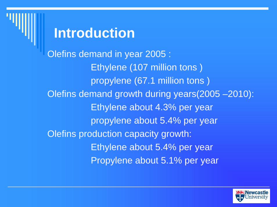
IntroductionOlefins demand in year 2005 :
Ethylene (107 million tons )propylene (67.1 million tons )
Olefins demand growth during years(2005 –2010):Ethylene about 4.3% per yearpropylene about 5.4% per year
Olefins production capacity growth:Ethylene about 5.4% per yearPropylene about 5.1% per year
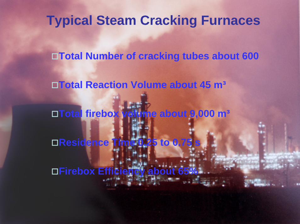
Typical Steam Cracking Furnaces
Total Number of cracking tubes about 600
Total Reaction Volume about 45 m³
Total firebox volume about 9,000 m³
Residence Time 0.25 to 0.75 s
Firebox Efficiency about 65%
Steam function and process limitation
Enhance heat transferReduce coke formation and depositionImprove selectivity towards ethyleneOperation purposesCoke deposition is the main process limitations due to:- High tube skin temperature- High pressure drop
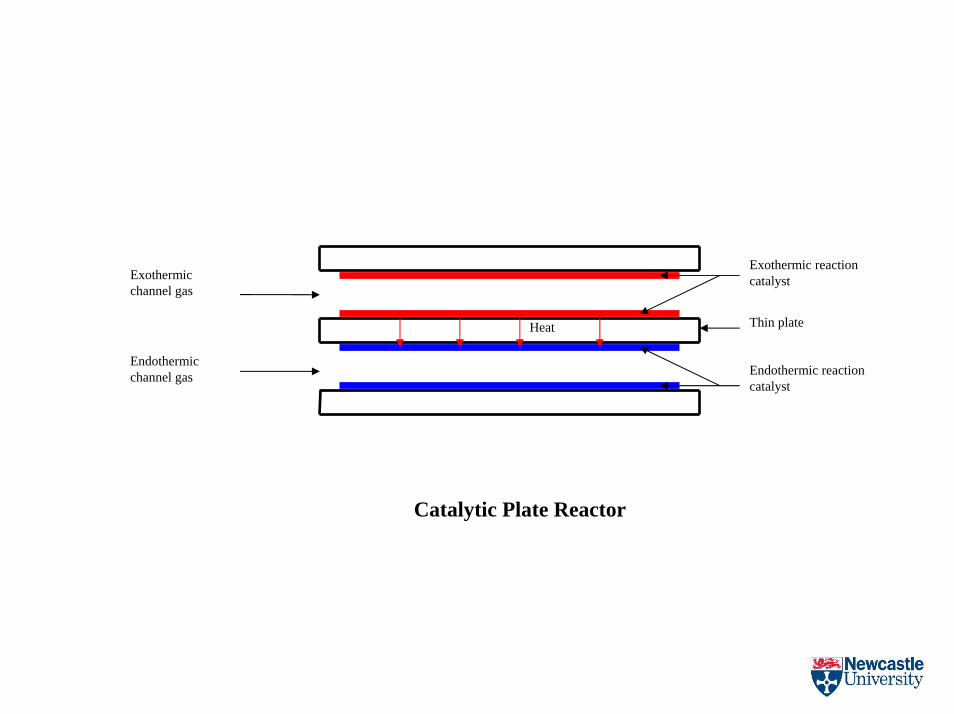
Exothermic channel gas
Endothermic channel gas
Heat
Exothermic reaction catalyst
Endothermic reaction catalyst
Catalytic Plate Reactor
Thin plate
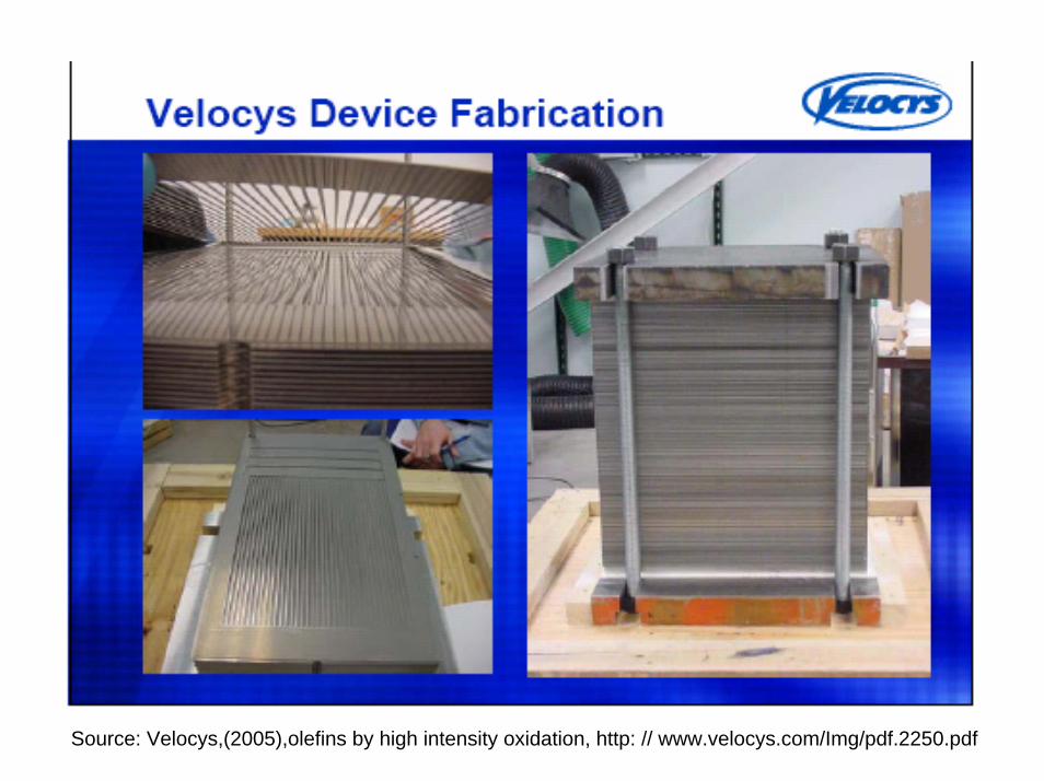
Source: Velocys,(2005),olefins by high intensity oxidation, http: // www.velocys.com/Img/pdf.2250.pdf
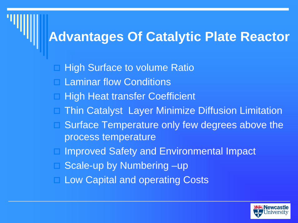
Advantages Of Catalytic Plate Reactor
High Surface to volume RatioLaminar flow ConditionsHigh Heat transfer CoefficientThin Catalyst Layer Minimize Diffusion LimitationSurface Temperature only few degrees above the process temperatureImproved Safety and Environmental ImpactScale-up by Numbering –upLow Capital and operating Costs
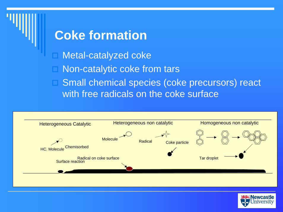
Coke formationMetal-catalyzed cokeNon-catalytic coke from tarsSmall chemical species (coke precursors) react with free radicals on the coke surface
Chemisorbed
Surface reaction
Heterogeneous Catalytic
HC. Molecule
Heterogeneous non catalytic
RadicalMolecule
Radical on coke surface
Coke particle
Homogeneous non catalytic
Tar droplet
Objectives
1-Study and investigate the possibility of intensifying the thermal cracking of propane to produce ethylene through the use of the catalytic plate reactors.
2- Reducing the coke formation and deposition.
3- Reducing the use of steam.
4- Modelling and simulation for propane cracking using Catalytic Plate Reactor.
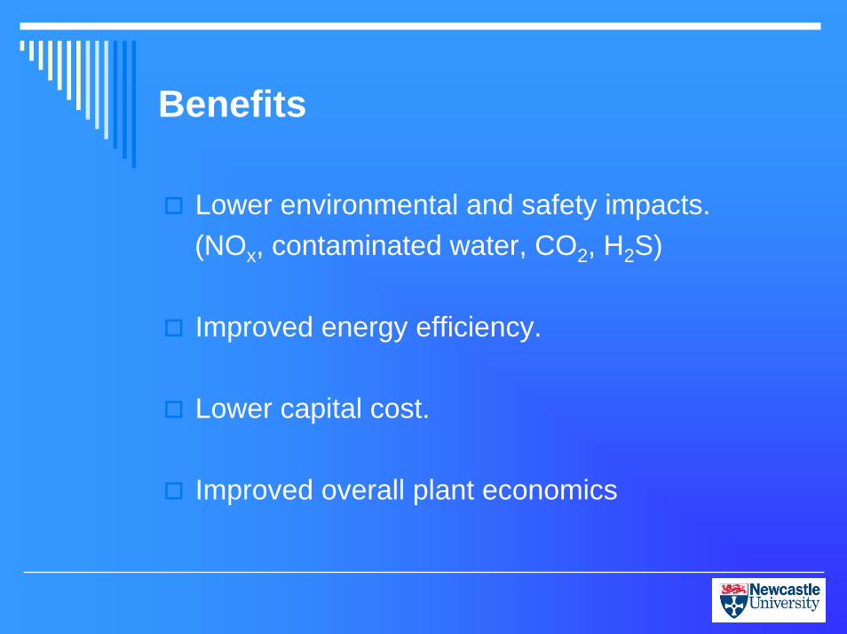
Benefits
Lower environmental and safety impacts.(NOx, contaminated water, CO2, H2S)
Improved energy efficiency.
Lower capital cost.
Improved overall plant economics
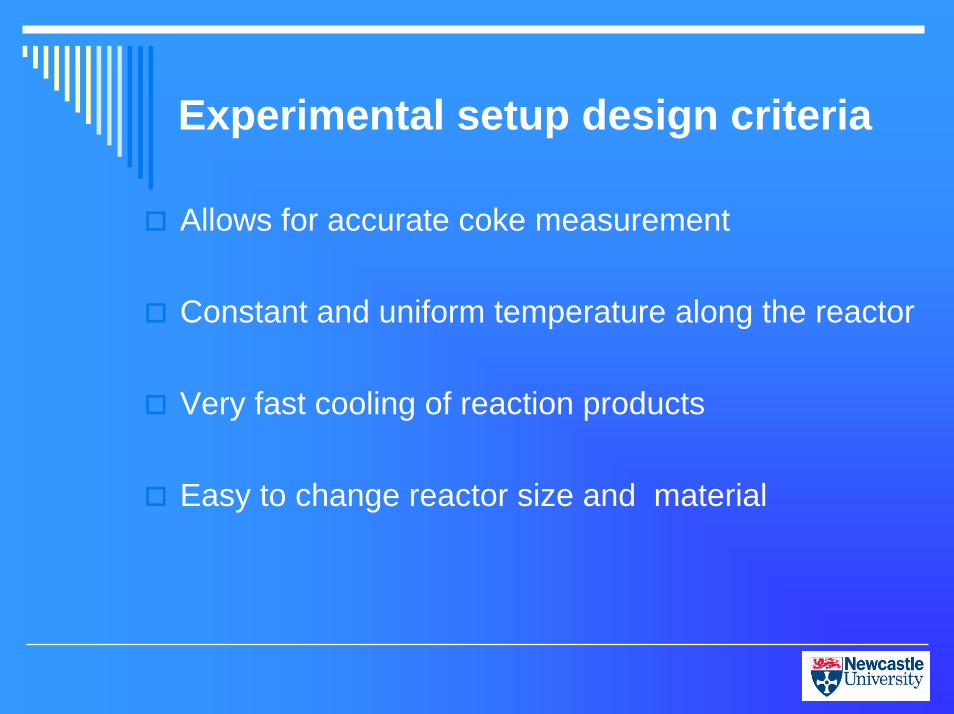
Experimental setup design criteria
Allows for accurate coke measurement
Constant and uniform temperature along the reactor
Very fast cooling of reaction products
Easy to change reactor size and material
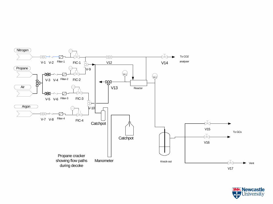
V-1 V-2 Filter-1
Nitrogen
V-3 V-4 Filter-2
Propane
V-5 V-6 Filter-3
Air
V-7 V-8 Filter-4
Argon
V-9
FIC-1
Reactor
V16
V17
Knock-out Vent
To GCs
PI-1
FIC-2
V-10
FIC-3
V12 V14
To CO2
analyser
PI-2
Propane crackershowing flow paths
during decoke
V13
V15
FIC-4
Manometer
Catchpot
Catchpot
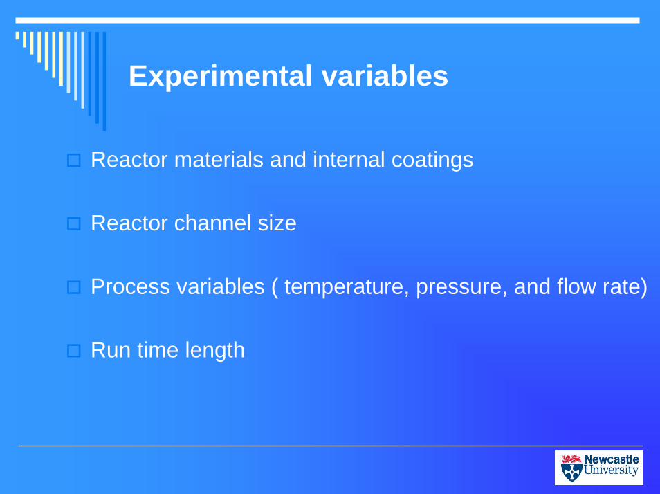
Experimental variables
Reactor materials and internal coatings
Reactor channel size
Process variables ( temperature, pressure, and flow rate)
Run time length
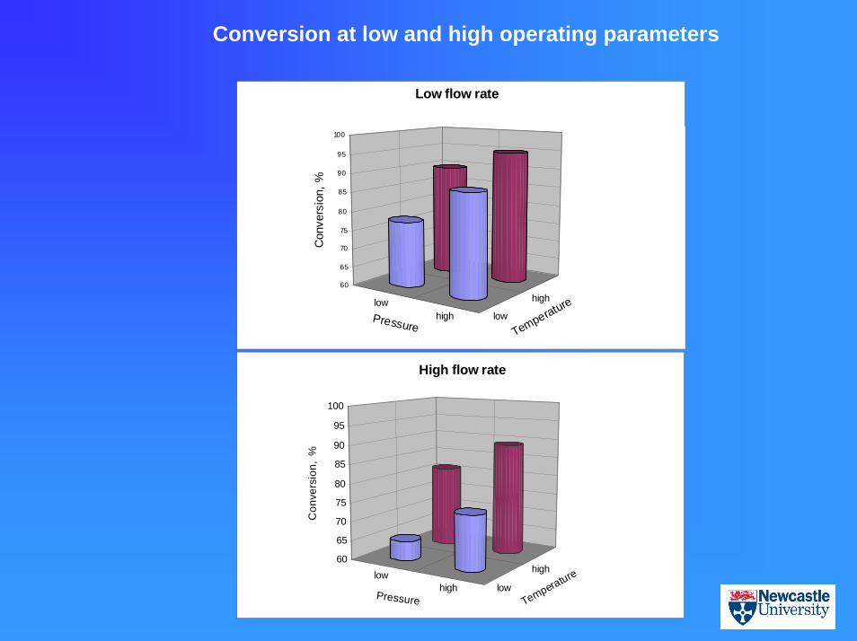
lowhigh low
high60
65
70
75
80
85
90
95
100
Con
vers
ion,
% Pressure Temperature
Low flow rate
lowhigh low
high60
65
70
75
80
85
90
95
100
Con
vers
ion,
%
Pressure Temperature
High flow rate
Conversion at low and high operating parameters
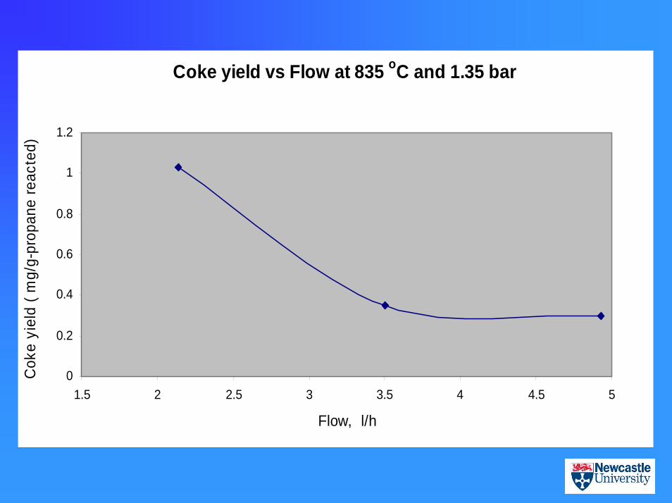
Coke yield vs Flow at 835 oC and 1.35 bar
0
0.2
0.4
0.6
0.8
1
1.2
1.5 2 2.5 3 3.5 4 4.5 5
Flow, l/h
Cok
e yi
eld
( mg/
g-pr
opan
e re
acte
d)
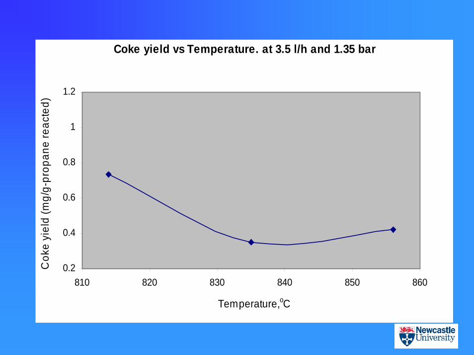
Coke yield vs Temperature. at 3.5 l/h and 1.35 bar
0.2
0.4
0.6
0.8
1
1.2
810 820 830 840 850 860
Temperature,oC
Cok
e yi
eld
(mg/
g-pr
opan
e re
acte
d)
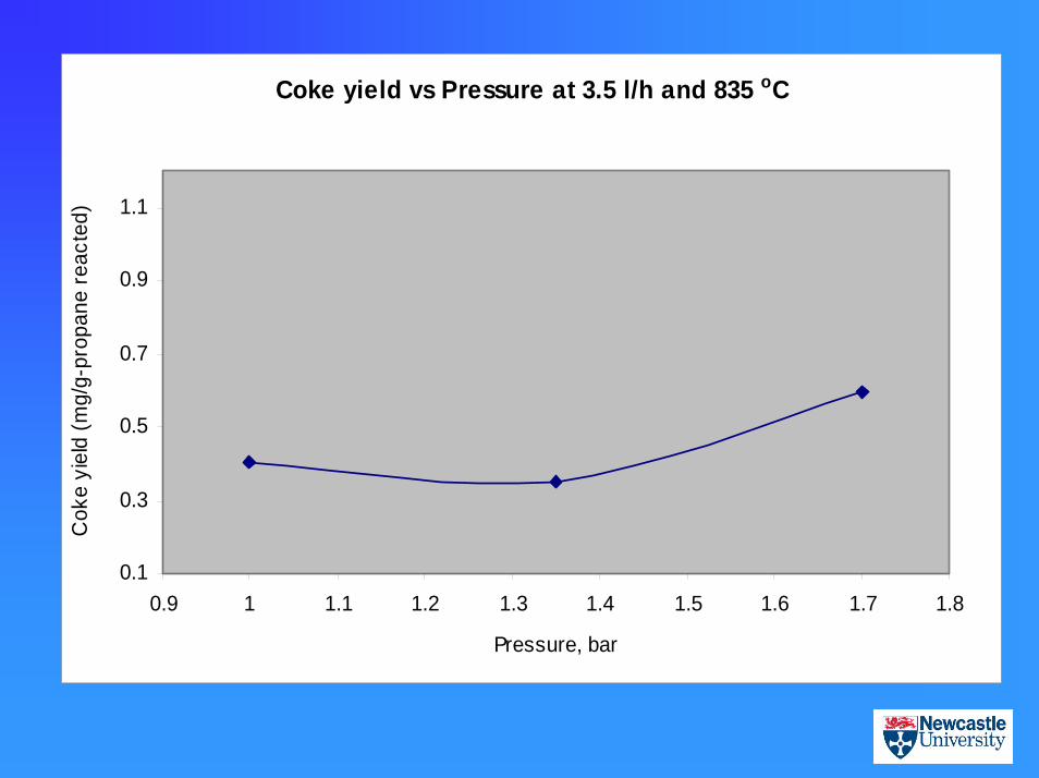
Coke yield vs Pressure at 3.5 l/h and 835 oC
0.1
0.3
0.5
0.7
0.9
1.1
0.9 1 1.1 1.2 1.3 1.4 1.5 1.6 1.7 1.8
Pressure, bar
Cok
e yi
eld
(mg/
g-pr
opan
e re
acte
d)
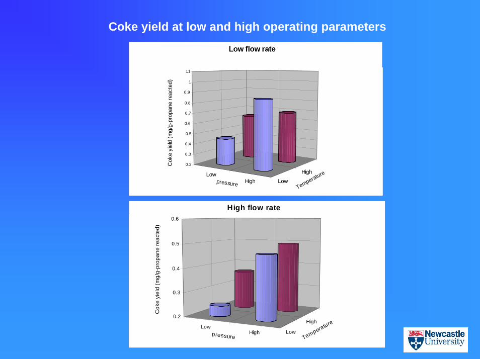
Coke yield at low and high operating parameters
LowHigh Low
High0.2
0.3
0.4
0.5
0.6
0.7
0.8
0.9
1
1.1
Cok
e yi
eld
(mg/
g-pr
opan
e re
acte
d)
pressure Temperature
Low flow rate
LowHigh Low
High0.2
0.3
0.4
0.5
0.6
Cok
e yi
eld
(mg/
g-pr
opan
e re
acte
d)
pressure Temperature
High flow rate
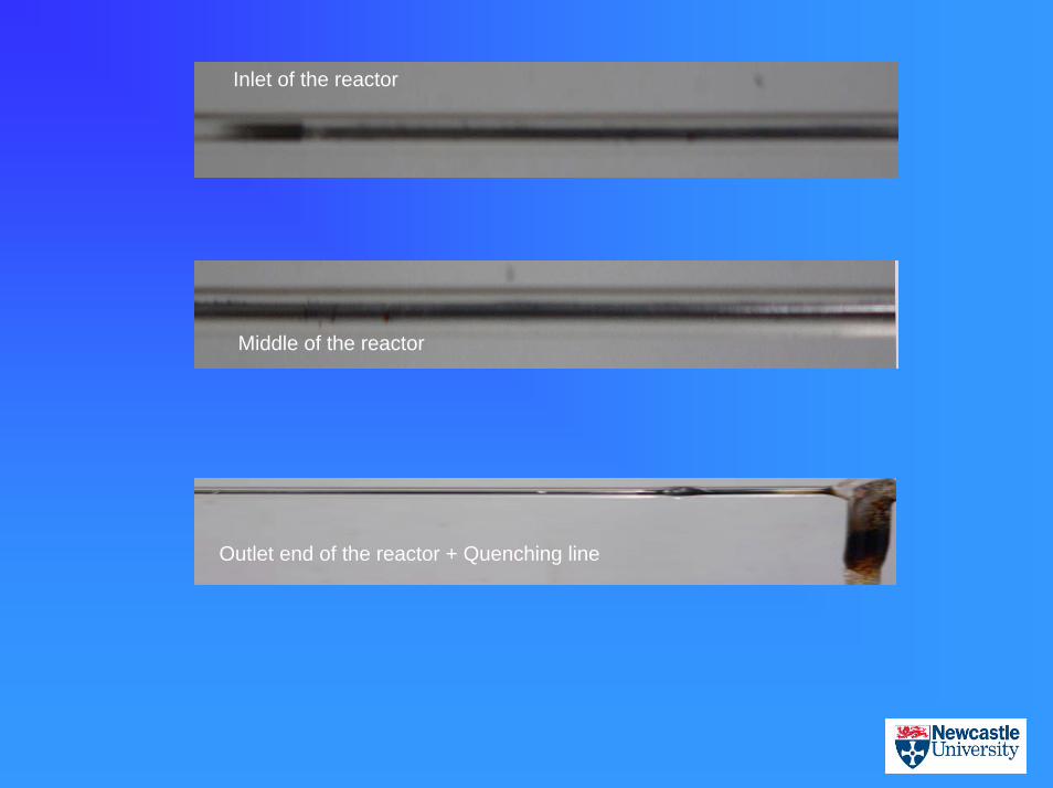
Inlet of the reactor
Middle of the reactor
Outlet end of the reactor + Quenching line
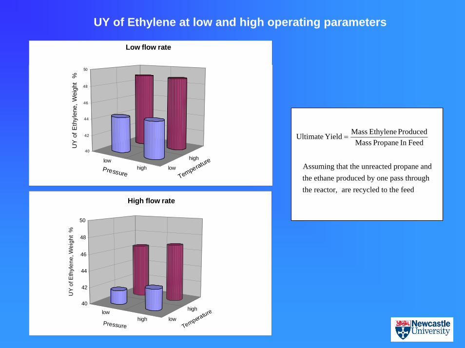
UY of Ethylene at low and high operating parameters
lowhigh low
high40
42
44
46
48
50U
Y o
f Eth
ylen
e, W
eigh
t %
Pressure Temperature
Low flow rate
lowhigh low
high40
42
44
46
48
50
UY
of E
thyl
ene,
Wei
ght
%
Pressure Temperature
High flow rate
FeedIn Propane MassProduced Ethylene MassYield Ultimate =
Assuming that the unreacted propane andthe ethane produced by one pass throughthe reactor, are recycled to the feed
Conclusions • Conversion of about 90 % can be achieved in 2 mm internal
diameter fused silica reactor without any significant pressure drop.
• Steam use can be reduced or possibly eliminated.
• High olefins yield can be obtained without steam.
• Low acetylene and C4+ yield.
• Run length of about 14 – 20 days was estimated to be possible before any decoking is required. This run length was achieved with no steam.

THANK YOU
![[Feb. 17, 2005] Integrating a Methanol to Olefin Reaction System With a Steam Cracking System](https://img.pdfslide.us/doc/110x75/563db797550346aa9a8c7915/feb-17-2005-integrating-a-methanol-to-olefin-reaction-system-with-a-steam.jpg)