Embed Size (px)
Citation preview
Installation Guide
MASOL40I-0002B
Created: 14/08/03
Last Updated: 04/02/04
2 Solution 40 Installation Manual
SUB-MASOL40I-0001.IG.C.doc
Table Of Contents
Features ...................................................................................................................................................9
Specifications.........................................................................................................................................10
Wiring Diagram....................................................................................................................................12
Telephone Line Connections................................................................................................................12
Installation.............................................................................................................................................13 Mounting The Enclosure................................................................................................................................................ 13 Installing The Control Panel PCB................................................................................................................................. 14 Mounting Expander Boards .......................................................................................................................................... 15
Text Keypad User's Guide ...................................................................................................................16 Introduction .................................................................................................................................................................... 16
Security System Basics .........................................................................................................................17 What Is A Zone? ............................................................................................................................................................. 17 What Is A "Faulted" Zone ?.......................................................................................................................................... 17 Are All Zones the Same ?............................................................................................................................................... 17 Away ................................................................................................................................................................................ 17 Stay .................................................................................................................................................................................. 17
Keypad Keys..........................................................................................................................................18 Status LED's.................................................................................................................................................................... 19 Area Icons........................................................................................................................................................................ 19
Keypad Tones........................................................................................................................................20
Commands.............................................................................................................................................20
System Events........................................................................................................................................21 Fire Alarms ..................................................................................................................................................................... 21 Burglary Alarms ............................................................................................................................................................. 21 Fire Trouble Events........................................................................................................................................................ 21 Non-Fire Trouble Events ............................................................................................................................................... 21
How Your System Reports Alarms .....................................................................................................22
Checking System Status .......................................................................................................................22
RF Keyfobs ............................................................................................................................................22
Silencing Alarms ...................................................................................................................................23
Disarming The System .........................................................................................................................24
Arming The System in Away mode, (Command 1) ...........................................................................25
Arming The System in Stay mode, (Command 2) .............................................................................26
Arming The System in Stay Mode 2, (Command 3)..........................................................................27
Set Stay 2 Zones, (Command 65).........................................................................................................28
Arming The System With No Entry Delay.........................................................................................29
Arming The System With No Exit Tone (Silent Delay).....................................................................31
Arming The System, With Zones Faulted (Force Arm)....................................................................32
Solution 40 Installation Manual 3
SUB-MASOL40I-0001.IG.C.doc
Viewing Faulted Zones, (Command 0)................................................................................................33
Bypassing Zones ....................................................................................................................................34
Date and Time, (Command 45)............................................................................................................35
Changing PIN Codes, (Command 55) .................................................................................................36
Change Other PIN Codes, (Command 56) .........................................................................................37 Change Other PIN Codes ...............................................................................................................................................38 Change PIN Code Authority Level................................................................................................................................39 Change PIN Code Area Assignment..............................................................................................................................40
Delete PIN codes, (Command 58) ........................................................................................................41
Renew One-Time PIN codes, (Command 53).....................................................................................42
Checking System Troubles, (Command 4) .........................................................................................43
View Alarm Memory, (Command 40).................................................................................................44
View System Trouble, (Command 42) ................................................................................................45
View Zone Trouble, (Command 48)....................................................................................................46
System Test, (Command 41) ................................................................................................................47
Walk Test, (Command 44) ...................................................................................................................49
Resetting The System, (Command 47) ................................................................................................50
Turn Chime On/Off, (Command 61)...................................................................................................51
Selecting Chime Tone, (Command 62)................................................................................................52
Selecting Chime Zones, (Command 63) ..............................................................................................53
Extend Auto On Time, (Command 51) ...............................................................................................54
Change Skeds, (Command 52).............................................................................................................55 Away Skeds......................................................................................................................................................................56 Stay Skeds ........................................................................................................................................................................57 Stay 2 Skeds .....................................................................................................................................................................58 Off Skeds..........................................................................................................................................................................59 Output On Skeds.............................................................................................................................................................60 Output Off Skeds ............................................................................................................................................................61
Toggle Outputs On/Off (Command 54) ..............................................................................................62
Remote Program, (Command 43)........................................................................................................63
Disarm All Areas, (Command 81) .......................................................................................................64
Arm All Areas, (Command 80)............................................................................................................65
Move To Area, (Command 50) ............................................................................................................66
Auto-Forward On Setup, (Command 83) ...........................................................................................68
Auto-Forward Off Setup, (Command 84)...........................................................................................69
Auto-Forward On/Off, (Command 82)...............................................................................................70
Adjust Keypad Volume (Command 49)..............................................................................................71
View Log, (Command 85).....................................................................................................................72
Security System Limitations ................................................................................................................77
Fire Safety and Evacuation ..................................................................................................................77
4 Solution 40 Installation Manual
SUB-MASOL40I-0001.IG.C.doc
Maintenance and Service .....................................................................................................................78
Power Failure ........................................................................................................................................78
How To Clean The Keypad..................................................................................................................78
Programming Via A ‘Text’ Keypad....................................................................................................79 Enter Installer’s Programming Mode........................................................................................................................... 79
Programming Option Bit Addresses...................................................................................................80
Programming Text Addresses .............................................................................................................80
Exit Installer’s Programming Mode ...................................................................................................80
Installer’s Menu....................................................................................................................................81 Enter Installer’s Menu ................................................................................................................................................... 81 RF Menu.......................................................................................................................................................................... 86 Program Key................................................................................................................................................................... 90 Call For Service .............................................................................................................................................................. 95
Programming Information ..................................................................................................................98 Telephone Reporting ...................................................................................................................................................... 98 Routing Tables ................................................................................................................................................................ 99 Securitel Format ........................................................................................................................................................... 101 Reporting Formats Table............................................................................................................................................. 104 Phone Number 1 For Destination 1............................................................................................................................. 112 Phone Number 2 For Destination 1............................................................................................................................. 112 Format For Destination 1............................................................................................................................................. 112 Phone Number 1 For Destination 2............................................................................................................................. 113 Phone Number 2 For Destination 2............................................................................................................................. 113 Format For Destination 2............................................................................................................................................. 113 DTMF / Pulse Dialling.................................................................................................................................................. 115 Auto-Forward On Sequence ........................................................................................................................................ 116 Auto-Forward Off Sequence........................................................................................................................................ 116 RPS Call Back Phone Number .................................................................................................................................... 117 Answer Ring Count ...................................................................................................................................................... 118 Phone Line Fail Response ............................................................................................................................................ 119 Global Reporting Options............................................................................................................................................ 120 Ack Wait Time .............................................................................................................................................................. 121 AC Power Supervision Options ................................................................................................................................... 121 AC Fail, Low/Missing Battery Report Options.......................................................................................................... 122 System Status Report Swinger Count ......................................................................................................................... 123 System Status Report Routing..................................................................................................................................... 123 Call For Service Interval.............................................................................................................................................. 123 System Inactive Interval............................................................................................................................................... 124 Call For Service/System Inactive Options .................................................................................................................. 124 Log Threshold/Overflow Options................................................................................................................................ 125 Auto Arming Pre-Alert Time....................................................................................................................................... 126 Cancel Alarm Reports.................................................................................................................................................. 126 Date and Time Display/Disable Pin Trouble .............................................................................................................. 127 Daylight Savings Calendar Options ............................................................................................................................ 127 Daylight Savings – Forward One Hour ...................................................................................................................... 128 Daylight Savings – Backwards One Hour .................................................................................................................. 128 AC Fail Report Delay ................................................................................................................................................... 128 System Test (Command 41) Configuration Options.................................................................................................. 128
Solution 40 Installation Manual 5
SUB-MASOL40I-0001.IG.C.doc
System Test (Command 41) Area Assignment ...........................................................................................................129 Walk Test (Command 44) Configuration Options.....................................................................................................130 Walk Test (Command 44) Area Assignment ..............................................................................................................131 Walk Test (Command 44) Start / End Report Routing .............................................................................................131 Test Report Options......................................................................................................................................................132 Test Report Time ..........................................................................................................................................................133 Test Report Interval......................................................................................................................................................133 Test Report Routing......................................................................................................................................................134 Remote Programming Options (RPS) .........................................................................................................................135 Programming/Daylight Savings Options ....................................................................................................................136 Arming Option 1 ...........................................................................................................................................................137 Arming Options 2..........................................................................................................................................................138 Zone Bypass / Force Arm Limit...................................................................................................................................139 Open/Close Report Options .........................................................................................................................................140 Open/Close Report Routing .........................................................................................................................................141 Exit Time Restart ..........................................................................................................................................................141
Entry/Exit Timers ...............................................................................................................................142 Programming.................................................................................................................................................................142 Entry Delay Time 1 .......................................................................................................................................................142 Entry Delay Time 2 .......................................................................................................................................................143 Stay Mode Delay Time..................................................................................................................................................143 Exit Delay Time 1..........................................................................................................................................................144 Exit Delay Time 2..........................................................................................................................................................144
Areas.....................................................................................................................................................145 Area 1 Account Number For Destination 1 ................................................................................................................145 Area 1 Account Number For Destination 2 ................................................................................................................145 Area 1 - Open/Close Report Options...........................................................................................................................145 Area 1 - Lock Reporting...............................................................................................................................................147 Area 2 Account Number For Destination 1 ................................................................................................................148 Area 2 Account Number For Destination 2 ................................................................................................................148 Area 2 - Open/Close Report Options...........................................................................................................................149 Area 2 - Lock Reporting...............................................................................................................................................150 Area 3 Account Number For Destination 1 ................................................................................................................151 Area 3 Account Number For Destination 2 ................................................................................................................151 Area 3 - Open/Close Report Options...........................................................................................................................152 Area 3 - Lock Reporting...............................................................................................................................................153 Area 4 Account Number For Destination 1 ................................................................................................................154 Area 4 Account Number For Destination 2 ................................................................................................................154 Area 4 - Open/Close Report Options...........................................................................................................................155 Area 4 - Lock Reporting...............................................................................................................................................156
Authority Levels..................................................................................................................................157 Authority Level Option 1 .............................................................................................................................................157 Authority Level Option 2 .............................................................................................................................................157 Authority Level Option 3 .............................................................................................................................................158 Authority Level Option 4 .............................................................................................................................................158 Authority Level Option 5 .............................................................................................................................................158 Authority Level Option 6 .............................................................................................................................................159 Authority Level Option 7 .............................................................................................................................................159 Authority Level Option 8 .............................................................................................................................................160 Authority Level Option 9 .............................................................................................................................................160
6 Solution 40 Installation Manual
SUB-MASOL40I-0001.IG.C.doc
Authority Level Option 10 ........................................................................................................................................... 161 Authority Level Option 11 ........................................................................................................................................... 161 Authority Level Option 12 ........................................................................................................................................... 161 Authority Level Option 13 ........................................................................................................................................... 162 Authority Level Option 14 ........................................................................................................................................... 162 Authority Level Option 15 ........................................................................................................................................... 162
PIN Code Configurations...................................................................................................................163 PIN Code Length .......................................................................................................................................................... 163 User Code Tamper, Retry Count ................................................................................................................................ 164 User Code Tamper Time.............................................................................................................................................. 164 Installer Code................................................................................................................................................................ 165 PIN Codes...................................................................................................................................................................... 165 Default PIN Codes ........................................................................................................................................................ 166
Keypads ...............................................................................................................................................168 Keypad Options ............................................................................................................................................................ 169 Keypad Area Assignment............................................................................................................................................. 169 A-Key Area Assignment............................................................................................................................................... 170 A-Key Alarm Response Options.................................................................................................................................. 170 B-Key Area Assignment ............................................................................................................................................... 171 B-Key Alarm Response Options.................................................................................................................................. 171 C-Key Area Assignment............................................................................................................................................... 172 C-Key Alarm Response Options.................................................................................................................................. 172 Alarm Output For A, B, C Keys.................................................................................................................................. 173 A, B, C Key Reports, Acknowledgement Beep........................................................................................................... 173 Duress Code Options .................................................................................................................................................... 173 A, B, C Key and Duress Report Routing .................................................................................................................... 175 Keypad Tamper Response ........................................................................................................................................... 175 Guard Code Options .................................................................................................................................................... 176
Zones ....................................................................................................................................................176 Zone / SDI Device Table............................................................................................................................................... 176 Input Device .................................................................................................................................................................. 178 Zone Index Configuration............................................................................................................................................ 179 Area Assignment........................................................................................................................................................... 179 Zone Number ................................................................................................................................................................ 179 Zone Defaults ................................................................................................................................................................ 180
Zone Index Configuration..................................................................................................................182 Zone Index Defaults...................................................................................................................................................... 182 Zone Type...................................................................................................................................................................... 184 Zone Pulse Count.......................................................................................................................................................... 188 Zone Pulse Count Time................................................................................................................................................ 188 Zone Index Options 1 (Non Keyswitch) ...................................................................................................................... 189 Zone Index Options 1 (Keyswitch) .............................................................................................................................. 190 Zone Index Options 2 ................................................................................................................................................... 191 Alarm / Trouble Response and Reporting Options ................................................................................................... 192 Alarm Report Routing ................................................................................................................................................. 193 Alarm Restore Report Routing ................................................................................................................................... 193
Global Zone Configuration................................................................................................................194 EOL Resistor Value (On-Board Zones Only) ............................................................................................................ 194 Zone Response Options ................................................................................................................................................ 195
Solution 40 Installation Manual 7
SUB-MASOL40I-0001.IG.C.doc
Bypass/Force Bypass Report Routing .........................................................................................................................196 Swinger Count For Alarm Output ..............................................................................................................................197 Swinger Count For Zone Reports................................................................................................................................197 Bypass, Swinger Bypass, Sensor Monitor Report Options........................................................................................198 Sensor Monitor Time ....................................................................................................................................................199 Alarm Report Abort Time............................................................................................................................................200 Zone Trouble Report / Restore Report Routing.........................................................................................................200
Global Output Configurations...........................................................................................................201 Global Output Options .................................................................................................................................................201 Siren Time......................................................................................................................................................................202 Horn Speaker Frequency .............................................................................................................................................202 Horn Speaker Beep Volume.........................................................................................................................................202 Strobe Function Options ..............................................................................................................................................203
Outputs.................................................................................................................................................204 Programming.................................................................................................................................................................204 On-Board Outputs ........................................................................................................................................................205 Off-Board Outputs........................................................................................................................................................205 Output Defaults .............................................................................................................................................................206 Area Assignment ...........................................................................................................................................................207 Event Types ...................................................................................................................................................................207 Mode...............................................................................................................................................................................216 Time Base.......................................................................................................................................................................218 Time Base Multiplier ....................................................................................................................................................218
Skeds.....................................................................................................................................................219 Type................................................................................................................................................................................220 Area/Output...................................................................................................................................................................221 Time................................................................................................................................................................................221 Sked Option 1 ................................................................................................................................................................221 Sked Option 2 ................................................................................................................................................................221 Sked Defaults.................................................................................................................................................................222 RF Receiver Options.....................................................................................................................................................223 RF Receiver Supervision Interval................................................................................................................................224 RF Receiver Jam Detect ...............................................................................................................................................224 DX4010 – RS232 Serial Interface Module Supervision Options...............................................................................225 DX4010 – RS232 Serial Interface Configuration Baud Rate ....................................................................................225 DX4010 – RS232 Serial Interface Configuration Parity, Flow Control Stop Bit ....................................................226 DX8010 - DTMF Telephone Command Module ........................................................................................................226 DX2010 Configuration Options ..............................................................................................................................226 AC Fail & Ground Fault Trouble Tone ......................................................................................................................227
Keypad Text Displays .........................................................................................................................228
RF Keypads – Future Release............................................................................................................234 Defaults ..........................................................................................................................................................................234 Options / Area Assignment...........................................................................................................................................234
RF Keyfobs ..........................................................................................................................................235 RF Keyfob Receiver Assignment Options...................................................................................................................235 RF Keyfob Options .......................................................................................................................................................236 Return To Factory Default...........................................................................................................................................236 Tamper Alarm / Trouble Configuration.....................................................................................................................237 System Alarm Reports Configuration.........................................................................................................................238
8 Solution 40 Installation Manual
SUB-MASOL40I-0001.IG.C.doc
Tamper Reset / Arming Options ................................................................................................................................. 239 Contact Set / Exit Delay Cancel Options .................................................................................................................... 240 Exit Terminator Areas ................................................................................................................................................. 240 Panel Arming Options.................................................................................................................................................. 241 Verified Alarm Timer................................................................................................................................................... 241 Personal Dialling Format Configuration ............................................................................................................... 242
Glossary ...............................................................................................................................................243
Terminals.............................................................................................................................................247
Option Bus Address Chart.................................................................................................................248
Optional Accessories...........................................................................................................................249 Option Bus Devices....................................................................................................................................................... 249 CP7446 Text Keypad.................................................................................................................................................... 250 DX2010 Zone Input Expansion Module ..................................................................................................................... 252 DX3010 Octo-Output Module...................................................................................................................................... 254 DX4010 RS-232 Serial Interface Module.................................................................................................................... 256 RF3227E – RF Receiver (433 MHz)............................................................................................................................ 259
Quick Reference Guide ......................................................................................................................261
Index.....................................................................................................................................................288
Solution 40 Installation Manual 9
SUB-MASOL40I-0001.IG.C.doc
Features Listed below are the main features of the SOLUTION 40 control panel.
• 40 Fully Programmable Zones
• Fire Alarm Verification
• 32 PIN codes
• 32 RF Keyfobs
• 4 On-Board Outputs (Max 20 Outputs)
• Supervised Siren Driver
• 8 Programmable Schedules (Skeds)
• Partitionable (1 – 4 Areas)
• Built-In Dialler (reports (Contact ID, SIA, Securitel and Pager formats)
• Up To 8 Fully Supervised Keypads
• Keyswitch Input (programmable)
• 254 History Event Memory
• EMI / Lightning Transient Protection
• Programmable Via Text Keypad
• Remote Programmable Via RPS Upload/Download Software
• Alarm Event Memory
• Automatic Test Reports
• Built-In Telephone Line Fail Monitor
• Securitel Compatible
10 Solution 40 Installation Manual
SUB-MASOL40I-0001.IG.C.doc
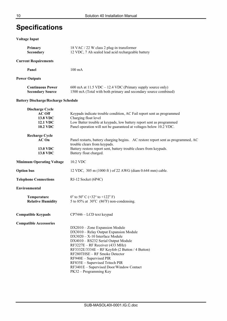
Specifications Voltage Input
Primary 18 VAC / 22 W class 2 plug-in transformer Secondary 12 VDC, 7 Ah sealed lead acid rechargeable battery
Current Requirements
Panel 100 mA Power Outputs
Continuous Power 600 mA at 11.5 VDC – 12.4 VDC (Primary supply source only) Secondary Source 1500 mA (Total with both primary and secondary source combined)
Battery Discharge/Recharge Schedule
Discharge Cycle AC Off Keypads indicate trouble condition, AC Fail report sent as programmed 13.8 VDC Charging float level 12.1 VDC Low Batter trouble at keypads, low battery report sent as programmed 10.2 VDC Panel operation will not be guaranteed at voltages below 10.2 VDC.
Recharge Cycle
AC On Panel restarts, battery charging begins. AC restore report sent as programmed, AC trouble clears from keypads.
13.0 VDC Battery restore report sent, battery trouble clears from keypads. 13.8 VDC Battery float charged.
Minimum Operating Voltage 10.2 VDC Option bus 12 VDC, 305 m (1000 ft ) of 22 AWG (diam 0.644 mm) cable. Telephone Connections RJ-12 Socket (6P4C) Environmental
Temperature 0o to 50o C (+32O to +122o F) Relative Humidity 5 to 85% at 30oC (86oF) non-condensing.
Compatible Keypads CP7446 – LCD text keypad Compatible Accessories DX2010 – Zone Expansion Module DX3010 – Relay Output Expansion Module DX3020 – X-10 Interface Module DX4010 – RS232 Serial Output Module RF3227E – RF Receiver (433 MHz) RF3332E/3334E – RF Keyfob (2 Button / 4 Button) RF280THSE – RF Smoke Detector RF940E – Supervised PIR RF835E – Supervised Tritech PIR RF3401E – Supervised Door/Window Contact PK32 – Programming Key
Solution 40 Installation Manual 11
SUB-MASOL40I-0001.IG.C.doc
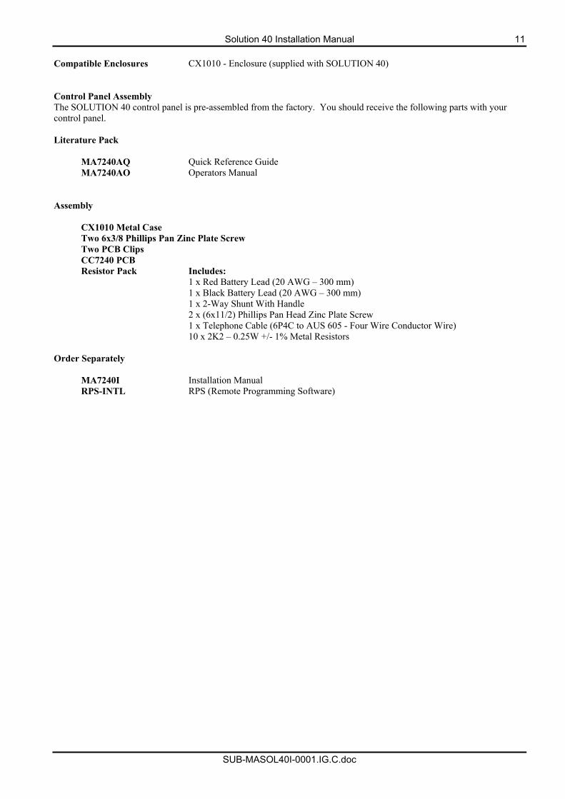
Compatible Enclosures CX1010 - Enclosure (supplied with SOLUTION 40) Control Panel Assembly The SOLUTION 40 control panel is pre-assembled from the factory. You should receive the following parts with your control panel. Literature Pack
MA7240AQ Quick Reference Guide MA7240AO Operators Manual
Assembly
CX1010 Metal Case Two 6x3/8 Phillips Pan Zinc Plate Screw Two PCB Clips CC7240 PCB Resistor Pack Includes:
1 x Red Battery Lead (20 AWG – 300 mm) 1 x Black Battery Lead (20 AWG – 300 mm) 1 x 2-Way Shunt With Handle 2 x (6x11/2) Phillips Pan Head Zinc Plate Screw 1 x Telephone Cable (6P4C to AUS 605 - Four Wire Conductor Wire) 10 x 2K2 – 0.25W +/- 1% Metal Resistors Order Separately
MA7240I Installation Manual RPS-INTL RPS (Remote Programming Software)
12 Solution 40 Installation Manual
SUB-MASOL40I-0001.IG.C.doc
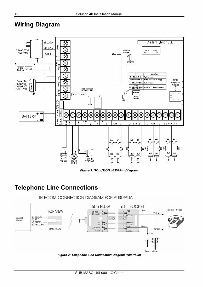
Wiring Diagram
Figure 1: SOLUTION 40 Wiring Diagram
Telephone Line Connections
Figure 2: Telephone Line Connection Diagram (Australia)
Solution 40 Installation Manual 13
SUB-MASOL40I-0001.IG.C.doc
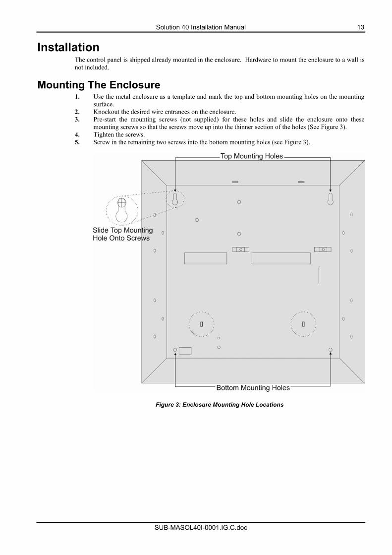
Installation The control panel is shipped already mounted in the enclosure. Hardware to mount the enclosure to a wall is not included.
Mounting The Enclosure 1. Use the metal enclosure as a template and mark the top and bottom mounting holes on the mounting
surface. 2. Knockout the desired wire entrances on the enclosure. 3. Pre-start the mounting screws (not supplied) for these holes and slide the enclosure onto these
mounting screws so that the screws move up into the thinner section of the holes (See Figure 3). 4. Tighten the screws. 5. Screw in the remaining two screws into the bottom mounting holes (see Figure 3).
Figure 3: Enclosure Mounting Hole Locations
14 Solution 40 Installation Manual
SUB-MASOL40I-0001.IG.C.doc
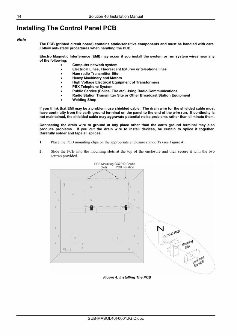
Installing The Control Panel PCB Note
The PCB (printed circuit board) contains static-sensitive components and must be handled with care. Follow anti-static procedures when handling the PCB. Electro Magnetic Interference (EMI) may occur if you install the system or run system wires near any of the following:
• Computer network system • Electrical Lines, Fluorescent fixtures or telephone lines • Ham radio Transmitter Site • Heavy Machinery and Motors • High Voltage Electrical Equipment of Transformers • PBX Telephone System • Public Service (Police, Fire etc) Using Radio Communications • Radio Station Transmitter Site or Other Broadcast Station Equipment • Welding Shop
If you think that EMI may be a problem, use shielded cable. The drain wire for the shielded cable must have continuity from the earth ground terminal on the panel to the end of the wire run. If continuity is not maintained, the shielded cable may aggravate potential noise problems rather than eliminate them. Connecting the drain wire to ground at any place other than the earth ground terminal may also produce problems. If you cut the drain wire to install devices, be certain to splice it together. Carefully solder and tape all splices.
1. Place the PCB mounting clips on the appropriate enclosure standoff's (see Figure 4).
2. Slide the PCB into the mounting slots at the top of the enclosure and then secure it with the two
screws provided.
Figure 4: Installing The PCB
Solution 40 Installation Manual 15
SUB-MASOL40I-0001.IG.C.doc
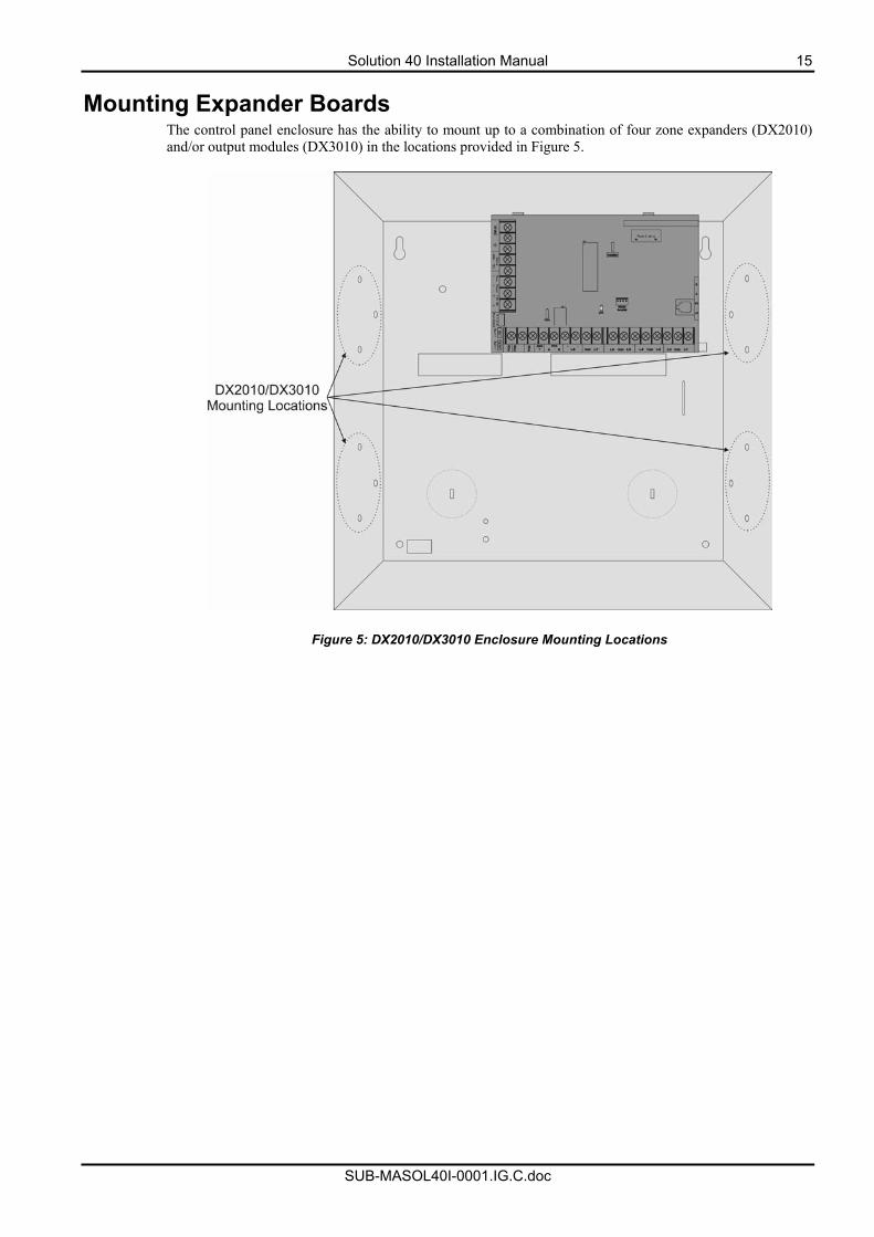
Mounting Expander Boards The control panel enclosure has the ability to mount up to a combination of four zone expanders (DX2010) and/or output modules (DX3010) in the locations provided in Figure 5.
Figure 5: DX2010/DX3010 Enclosure Mounting Locations
16 Solution 40 Installation Manual
SUB-MASOL40I-0001.IG.C.doc
Text Keypad User's Guide This user's guide shows you how to use and maintain your security system. It covers basic functions, such as arming and disarming the system. The functions describe in this guide are programmed by your security company. Some of them may not be included in your system. Some of the functions covered may require you to enter your PIN Code.
Introduction Your system helps to secure life, property, and investments against fire, theft and bodily harm. It consists of a keypad (or keypads), sensors, such as motion detectors or devices located on doors and windows, and other sensing devices designed to detect the presence of smoke or combustion. Each of these devices is connected to a sophisticated electronic "brain", which processes all events registered by the system. Control of your security system is achieved through the keypad, which offers a variety of basic and advanced features. Its function, versatility, and ease of operation, make it ideal for home or office. The keypad is tailored to meet your individual needs. Moreover, it has been designed with you, the user, in mind.
Solution 40 Installation Manual 17
SUB-MASOL40I-0001.IG.C.doc
Security System Basics
What Is A Zone? A "Zone" is a detection device, or group of devices connected to your security system. Zones are identified by the area they monitor, such as a front door, bedroom window or hallway.
What Is A "Faulted" Zone ? When a zone (such as a door or window) is closed, it is said to be "normal". When the door or window is open, the zone is said to be "faulted" or not normal. When you arm your system, you will usually want all of the zones in your system to be normal, although, you can arm your system with faulted zones by using the Bypass Zones command. You can see whether there are faulted zones by pressing the [Select] key when the system is off.
Are All Zones the Same ? No. There are two basic types of zones, Controlled and 24-hour.
Controlled Zones Controlled zones respond to alarm conditions depending upon whether the system is armed or disarmed. They are programmed to either respond instantly to alarm conditions or to provide a delay for you to reach the keypad and disarm the system. Various controlled zones may be located throughout your premises. When you arm your system, you have the option of arming all controlled zones (Away mode), or just some of the controlled zones (Stay mode). Refer to and , on page 17 for more information. 24-Hour Zones 24-hour zones are always on, even when the system is disarmed. There are two types of 24-hour zones, fire zones and non-fire zones. Fire zones Fire zones only monitor fire detection devices, such as smoke detectors. They are always on and cannot be turned off. Non-fire 24-Hour Zones Non-fire 24-hour zones are always on and cannot be turned off.
Away When you arm your system in Away mode, you are turning on all controlled zones, both interior (motion detectors) and perimeter (doors and windows of the building).
Stay When you arm your system in Stay mode, you are turning on only a portion of the controlled zones. Your alarm company determines the particular zones included in this portion. Stay zones may include only the perimeter (doors and windows) or your system, or sensors in other areas of your premises. Check with your security company to learn which zones are Part zones.
18 Solution 40 Installation Manual
SUB-MASOL40I-0001.IG.C.doc
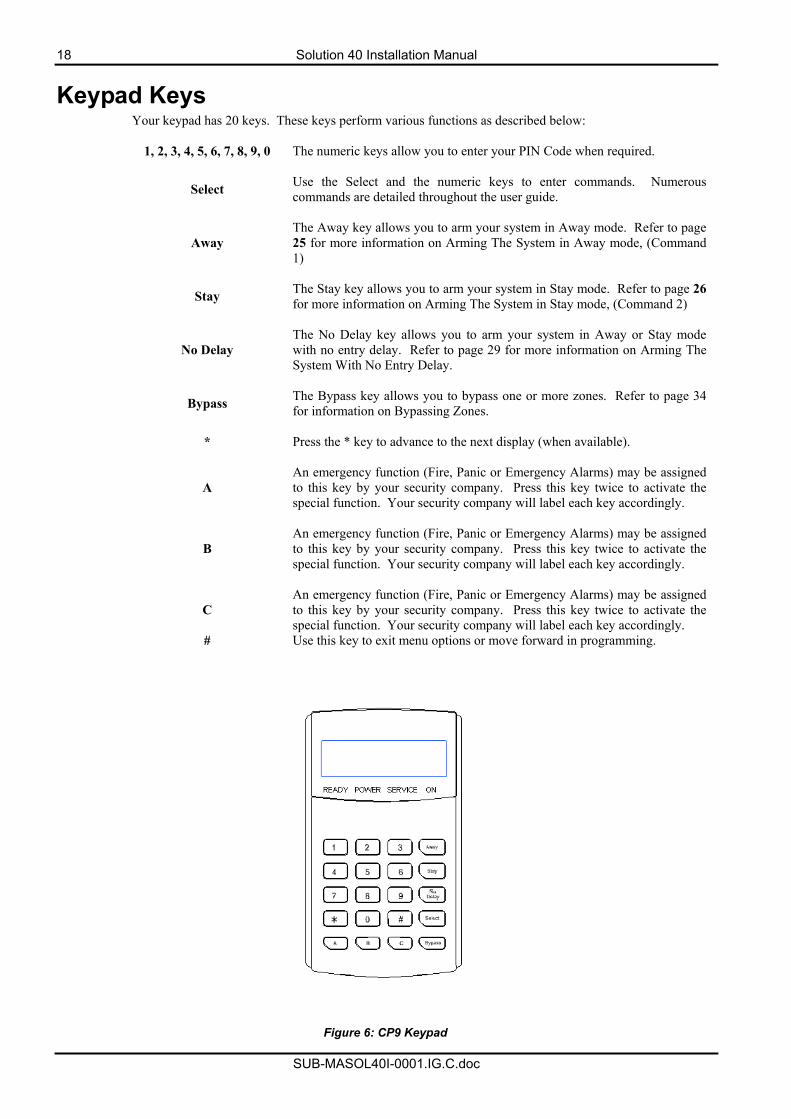
Keypad Keys Your keypad has 20 keys. These keys perform various functions as described below:
1, 2, 3, 4, 5, 6, 7, 8, 9, 0 The numeric keys allow you to enter your PIN Code when required.
Select Use the Select and the numeric keys to enter commands. Numerous commands are detailed throughout the user guide.
Away The Away key allows you to arm your system in Away mode. Refer to page 25 for more information on Arming The System in Away mode, (Command 1)
Stay The Stay key allows you to arm your system in Stay mode. Refer to page 26 for more information on Arming The System in Stay mode, (Command 2)
No Delay The No Delay key allows you to arm your system in Away or Stay mode with no entry delay. Refer to page 29 for more information on Arming The System With No Entry Delay.
Bypass The Bypass key allows you to bypass one or more zones. Refer to page 34 for information on Bypassing Zones.
* Press the * key to advance to the next display (when available).
A An emergency function (Fire, Panic or Emergency Alarms) may be assigned to this key by your security company. Press this key twice to activate the special function. Your security company will label each key accordingly.
B An emergency function (Fire, Panic or Emergency Alarms) may be assigned to this key by your security company. Press this key twice to activate the special function. Your security company will label each key accordingly.
C An emergency function (Fire, Panic or Emergency Alarms) may be assigned to this key by your security company. Press this key twice to activate the special function. Your security company will label each key accordingly.
# Use this key to exit menu options or move forward in programming.
Figure 6: CP9 Keypad
Solution 40 Installation Manual 19
SUB-MASOL40I-0001.IG.C.doc
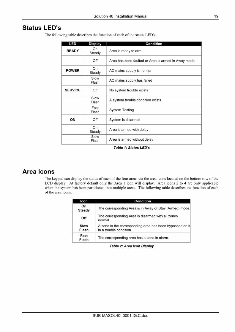
Status LED's The following table describes the function of each of the status LED's.
LED Display Condition
READY On Steady Area is ready to arm
Off Area has zone faulted or Area is armed in Away mode
POWER On Steady AC mains supply is normal
Slow Flash AC mains supply has failed
SERVICE Off No system trouble exists
Slow Flash A system trouble condition exists
Fast Flash System Testing
ON Off System is disarmed
On Steady Area is armed with delay
Slow Flash Area is armed without delay
Table 1: Status LED's
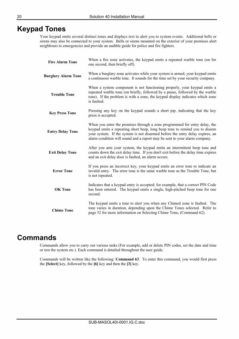
Area Icons The keypad can display the status of each of the four areas via the area icons located on the bottom row of the LCD display. At factory default only the Area 1 icon will display. Area icons 2 to 4 are only applicable when the system has been partitioned into multiple areas. The following table describes the function of each of the area icons.
Icon Condition On
Steady The corresponding Area is in Away or Stay (Armed) mode.
Off The corresponding Area is disarmed with all zones normal.
Slow Flash
A zone in the corresponding area has been bypassed or is in a trouble condition.
Fast Flash The corresponding area has a zone in alarm.
Table 2: Area Icon Display
20 Solution 40 Installation Manual
SUB-MASOL40I-0001.IG.C.doc
Keypad Tones Your keypad emits several distinct tones and displays text to alert you to system events. Additional bells or sirens may also be connected to your system. Bells or sirens mounted on the exterior of your premises alert neighbours to emergencies and provide an audible guide for police and fire fighters.
Fire Alarm Tone When a fire zone activates, the keypad emits a repeated warble tone (on for one second, then briefly off).
Burglary Alarm Tone When a burglary zone activates while your system is armed, your keypad emits a continuous warble tone. It sounds for the time set by your security company.
Trouble Tone
When a system component is not functioning properly, your keypad emits a repeated warble tone (on briefly, followed by a pause, followed by the warble tone). If the problem is with a zone, the keypad display indicates which zone is faulted.
Key Press Tone Pressing any key on the keypad sounds a short pip, indicating that the key press is accepted.
Entry Delay Tone
When you enter the premises through a zone programmed for entry delay, the keypad emits a repeating short beep, long beep tone to remind you to disarmyour system. If the system is not disarmed before the entry delay expires, an alarm condition will sound and a report may be sent to your alarm company.
Exit Delay Tone After you arm your system, the keypad emits an intermittent beep tone and counts down the exit delay time. If you don't exit before the delay time expires and an exit delay door is faulted, an alarm occurs.
Error Tone If you press an incorrect key, your keypad emits an error tone to indicate an invalid entry. The error tone is the same warble tone as the Trouble Tone, but is not repeated.
OK Tone Indicates that a keypad entry is accepted; for example, that a correct PIN Code has been entered. The keypad emits a single, high-pitched beep tone for one second.
Chime Tone
The keypad emits a tone to alert you when any Chimed zone is faulted. The tone varies in duration, depending upon the Chime Tones selected. Refer to page 52 for more information on Selecting Chime Tone, (Command 62).
Commands Commands allow you to carry out various tasks (For example, add or delete PIN codes, set the date and time or test the system etc.) Each command is detailed throughout the user guide. Commands will be written like the following: Command 63. To enter this command, you would first press the [Select] key, followed by the [6] key and then the [3] key.
Solution 40 Installation Manual 21
SUB-MASOL40I-0001.IG.C.doc
System Events Your system responds to four types of alarm events. If more than one event occurs, your system sorts them into one of four groups. The groups (highest in priority first) are: Fire Alarms, Burglary Alarms, Fire Troubles and Non-Fire Troubles.
Fire Alarms Fire alarms are the highest priority events. When a fire zone activates, your keypad emits a warble tone that is on for one second, then briefly off (repeatedly). The tone sounds for the time set by your security company. Evacuate all occupants and investigate for smoke or fire. Ensure that all occupants know the difference between the burglary tone and the fire tone.
Burglary Alarms Burglary alarms are the second priority. When a burglary zone activates while your system is armed, your keypad emits a constant warble tone. The tone sounds for the time set by your security company. The keypad display shows each burglary zone that went into alarm. Press the [*] key to manually scroll the list if you wish.
Fire Trouble Events When a fire trouble (such as a loose wire) occurs, your keypad emits a trouble tone, which is a warble tone that is on briefly, then followed by a pause, followed by the warble tone (repeatedly). The keypad displays the SYSTEM TROUBLE message. Refer to page 43 for more information on Checking System Troubles, (Command 4) to determine the nature of the trouble.
Non-Fire Trouble Events When a trouble event such as a power failure occurs, your keypad emits a trouble tone, which is a warble tone that is on briefly, followed by a pause, followed by the warble tone (repeatedly). The keypad displays the SYSTEM TROUBLE message. Refer to page 43 for more information on Checking System Troubles, (Command 4) to determine the nature of the trouble.
22 Solution 40 Installation Manual
SUB-MASOL40I-0001.IG.C.doc
How Your System Reports Alarms Your security system may be programmed to send reports to your security company. Once the report is complete, the system returns the telephone to normal operation (check with your security company). Your system makes repeated attempts to send reports to your security company. If your system fails to report, the keypad will signal a system trouble. Refer to page 43 for more information on Checking System Troubles, (Command 4) to determine the nature of the trouble.
Note If your telephone service is interrupted, your security system cannot send reports to your security company unless it has an alternate means of transmitting them.
Checking System Status When the system is Off, pressing the Command key shows the current system status. The following messages may appear:
System OK. Indicates that the system is ready to be armed. System Trouble! Press 4 to view.
Indicates that there is a system trouble. Refer to page 43 for more information on Checking System Troubles, (Command 4) to determine the nature of the trouble.
Zones bypassed. Press 0 to view.
Indicates that the system has zones that have been bypassed. Refer to page 34 for information on Bypassing Zones.
Zones faulted. Press 0 to view.
Indicates that the system has zones faulted. Refer to page 33 for information on Viewing Faulted Zones, (Command 0)
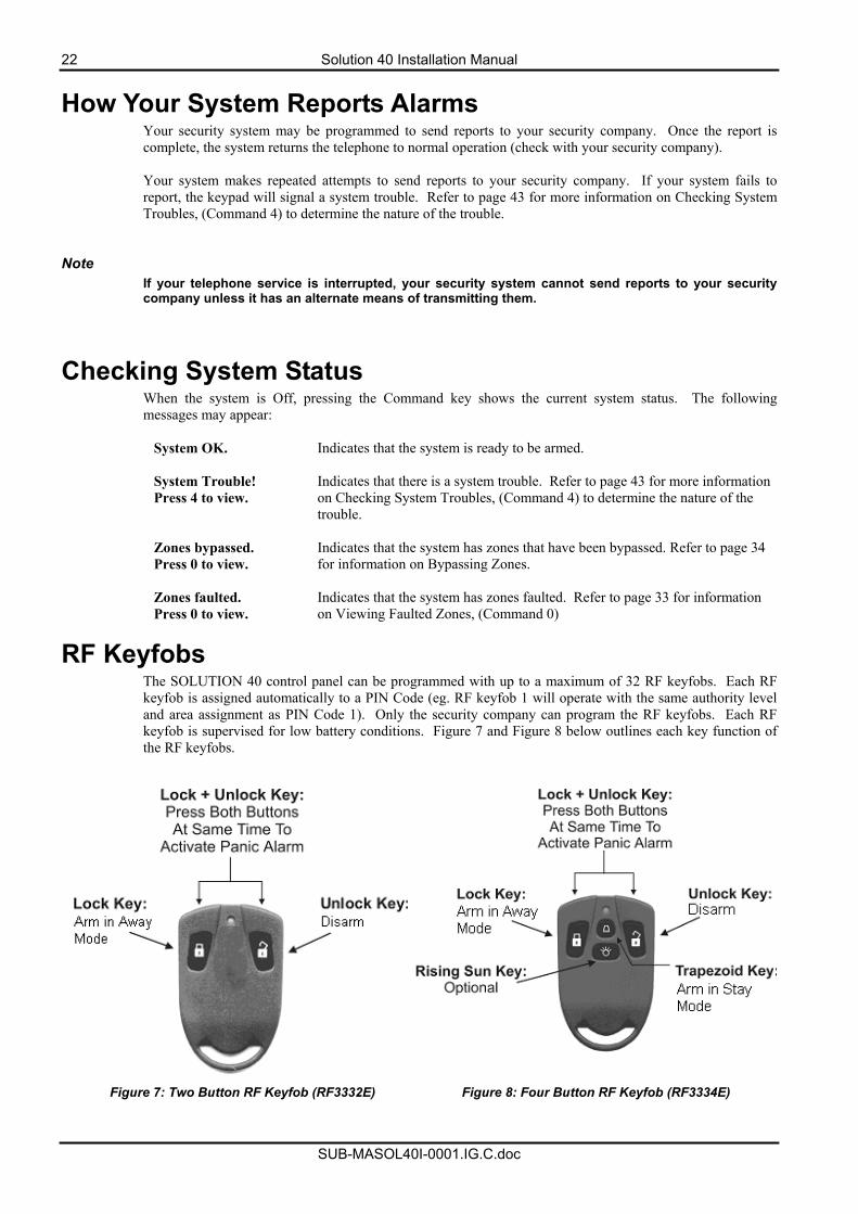
RF Keyfobs The SOLUTION 40 control panel can be programmed with up to a maximum of 32 RF keyfobs. Each RF keyfob is assigned automatically to a PIN Code (eg. RF keyfob 1 will operate with the same authority level and area assignment as PIN Code 1). Only the security company can program the RF keyfobs. Each RF keyfob is supervised for low battery conditions. Figure 7 and Figure 8 below outlines each key function of the RF keyfobs.
Figure 7: Two Button RF Keyfob (RF3332E) Figure 8: Four Button RF Keyfob (RF3334E)
Solution 40 Installation Manual 23
SUB-MASOL40I-0001.IG.C.doc
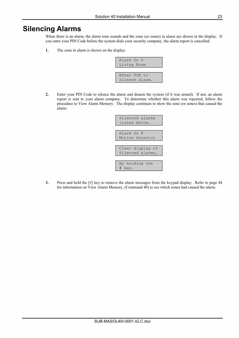
Silencing Alarms When there is an alarm, the alarm tone sounds and the zone (or zones) in alarm are shown in the display. If you enter your PIN Code before the system dials your security company, the alarm report is cancelled. 1. The zone in alarm is shown on the display:
Alarm Zn 4 Living Room
Enter PIN to silence alarm.
2. Enter your PIN Code to silence the alarm and disarm the system (if it was armed). If not, an alarm report is sent to your alarm company. To determine whether this alarm was reported, follow the procedure to View Alarm Memory. The display continues to show the zone (or zones) that caused the alarm:
Silenced alarms listed below.
Alarm Zn 8 Motion Detector
Clear display of Silenced alarms,
By holding the # key.
3. Press and hold the [#] key to remove the alarm messages from the keypad display. Refer to page 44 for information on View Alarm Memory, (Command 40) to see which zones had caused the alarm.
24 Solution 40 Installation Manual
SUB-MASOL40I-0001.IG.C.doc
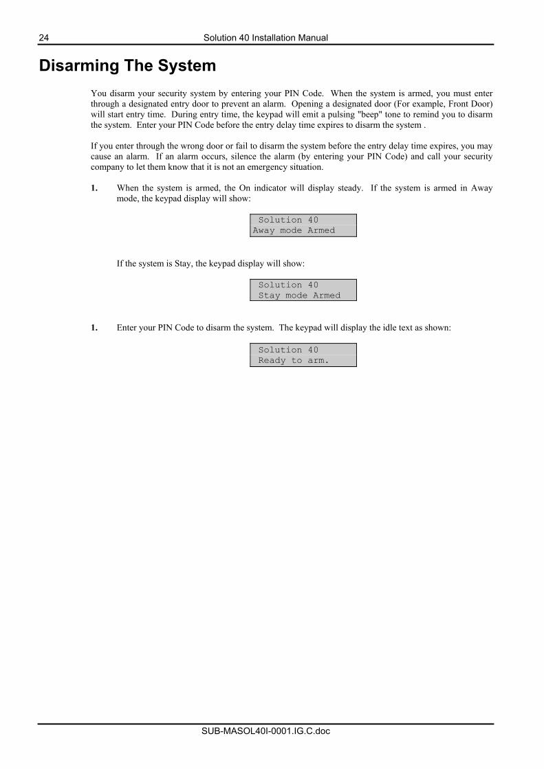
Disarming The System You disarm your security system by entering your PIN Code. When the system is armed, you must enter through a designated entry door to prevent an alarm. Opening a designated door (For example, Front Door) will start entry time. During entry time, the keypad will emit a pulsing "beep" tone to remind you to disarm the system. Enter your PIN Code before the entry delay time expires to disarm the system . If you enter through the wrong door or fail to disarm the system before the entry delay time expires, you may cause an alarm. If an alarm occurs, silence the alarm (by entering your PIN Code) and call your security company to let them know that it is not an emergency situation. 1. When the system is armed, the On indicator will display steady. If the system is armed in Away
mode, the keypad display will show:
Solution 40 Away mode Armed
If the system is Stay, the keypad display will show:
Solution 40 Stay mode Armed
1. Enter your PIN Code to disarm the system. The keypad will display the idle text as shown:
Solution 40 Ready to arm.
Solution 40 Installation Manual 25
SUB-MASOL40I-0001.IG.C.doc
Arming The System in Away mode, (Command 1)
I have this feature. I do not have this feature.
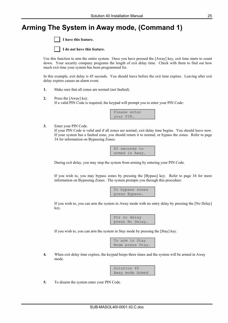
Use this function to arm the entire system. Once you have pressed the [Away] key, exit time starts to count down. Your security company programs the length of exit delay time. Check with them to find out how much exit time your system has been programmed for. In this example, exit delay is 45 seconds. You should leave before the exit time expires. Leaving after exit delay expires causes an alarm event. 1. Make sure that all zones are normal (not faulted).
2. Press the [Away] key.
If a valid PIN Code is required, the keypad will prompt you to enter your PIN Code:
Please enter your PIN.
3. Enter your PIN Code.
If your PIN Code is valid and if all zones are normal, exit delay time begins. You should leave now. If your system has a faulted zone, you should return it to normal, or bypass the zones. Refer to page 34 for information on Bypassing Zones.
45 seconds to armed in Away.
During exit delay, you may stop the system from arming by entering your PIN Code. If you wish to, you may bypass zones by pressing the [Bypass] key. Refer to page 34 for more information on Bypassing Zones. The system prompts you through this procedure:
To bypass zones press Bypass.
If you wish to, you can arm the system in Away mode with no entry delay by pressing the [No Delay] key.
For no delay press No Delay.
If you wish to, you can arm the system in Stay mode by pressing the [Stay] key.
To arm in Stay Mode press Stay.
4. When exit delay time expires, the keypad beeps three times and the system will be armed in Away
mode.
Solution 40 Away mode Armed
5. To disarm the system enter your PIN Code.
26 Solution 40 Installation Manual
SUB-MASOL40I-0001.IG.C.doc
Arming The System in Stay mode, (Command 2)
I have this feature. I do not have this feature.
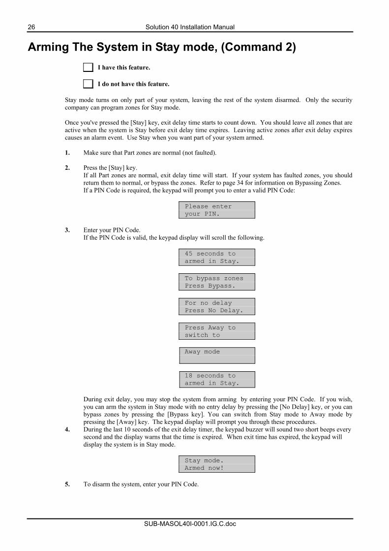
Stay mode turns on only part of your system, leaving the rest of the system disarmed. Only the security company can program zones for Stay mode. Once you've pressed the [Stay] key, exit delay time starts to count down. You should leave all zones that are active when the system is Stay before exit delay time expires. Leaving active zones after exit delay expires causes an alarm event. Use Stay when you want part of your system armed. 1. Make sure that Part zones are normal (not faulted).
2. Press the [Stay] key.
If all Part zones are normal, exit delay time will start. If your system has faulted zones, you should return them to normal, or bypass the zones. Refer to page 34 for information on Bypassing Zones. If a PIN Code is required, the keypad will prompt you to enter a valid PIN Code:
Please enter your PIN.
3. Enter your PIN Code.
If the PIN Code is valid, the keypad display will scroll the following.
45 seconds to armed in Stay.
To bypass zones Press Bypass.
For no delay Press No Delay.
Press Away to switch to
Away mode
18 seconds to armed in Stay.
During exit delay, you may stop the system from arming by entering your PIN Code. If you wish, you can arm the system in Stay mode with no entry delay by pressing the [No Delay] key, or you can bypass zones by pressing the [Bypass key]. You can switch from Stay mode to Away mode by pressing the [Away] key. The keypad display will prompt you through these procedures.
4. During the last 10 seconds of the exit delay timer, the keypad buzzer will sound two short beeps every second and the display warns that the time is expired. When exit time has expired, the keypad will display the system is in Stay mode.
Stay mode. Armed now!
5. To disarm the system, enter your PIN Code.
Solution 40 Installation Manual 27
SUB-MASOL40I-0001.IG.C.doc
Arming The System in Stay Mode 2, (Command 3)
I have this feature. I do not have this feature.
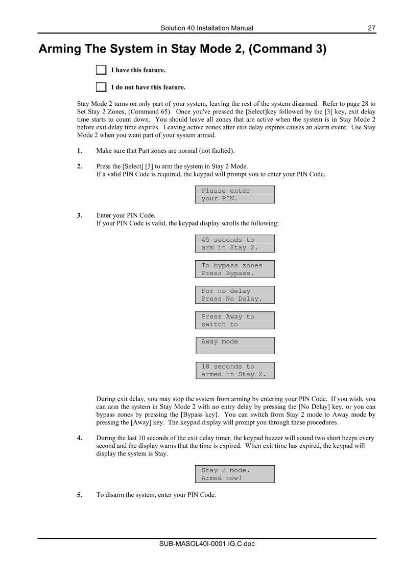
Stay Mode 2 turns on only part of your system, leaving the rest of the system disarmed. Refer to page 28 to Set Stay 2 Zones, (Command 65). Once you've pressed the [Select]key followed by the [3] key, exit delay time starts to count down. You should leave all zones that are active when the system is in Stay Mode 2 before exit delay time expires. Leaving active zones after exit delay expires causes an alarm event. Use Stay Mode 2 when you want part of your system armed. 1. Make sure that Part zones are normal (not faulted).
2. Press the [Select] [3] to arm the system in Stay 2 Mode.
If a valid PIN Code is required, the keypad will prompt you to enter your PIN Code.
Please enter your PIN.
3. Enter your PIN Code.
If your PIN Code is valid, the keypad display scrolls the following:
45 seconds to arm in Stay 2.
To bypass zones Press Bypass.
For no delay Press No Delay.
Press Away to switch to
Away mode
18 seconds to armed in Stay 2.
During exit delay, you may stop the system from arming by entering your PIN Code. If you wish, you can arm the system in Stay Mode 2 with no entry delay by pressing the [No Delay] key, or you can bypass zones by pressing the [Bypass key]. You can switch from Stay 2 mode to Away mode by pressing the [Away] key. The keypad display will prompt you through these procedures.
4. During the last 10 seconds of the exit delay timer, the keypad buzzer will sound two short beeps every
second and the display warns that the time is expired. When exit time has expired, the keypad will display the system is Stay.
Stay 2 mode. Armed now!
5. To disarm the system, enter your PIN Code.
28 Solution 40 Installation Manual
SUB-MASOL40I-0001.IG.C.doc
Set Stay 2 Zones, (Command 65)
I have this feature. I do not have this feature.
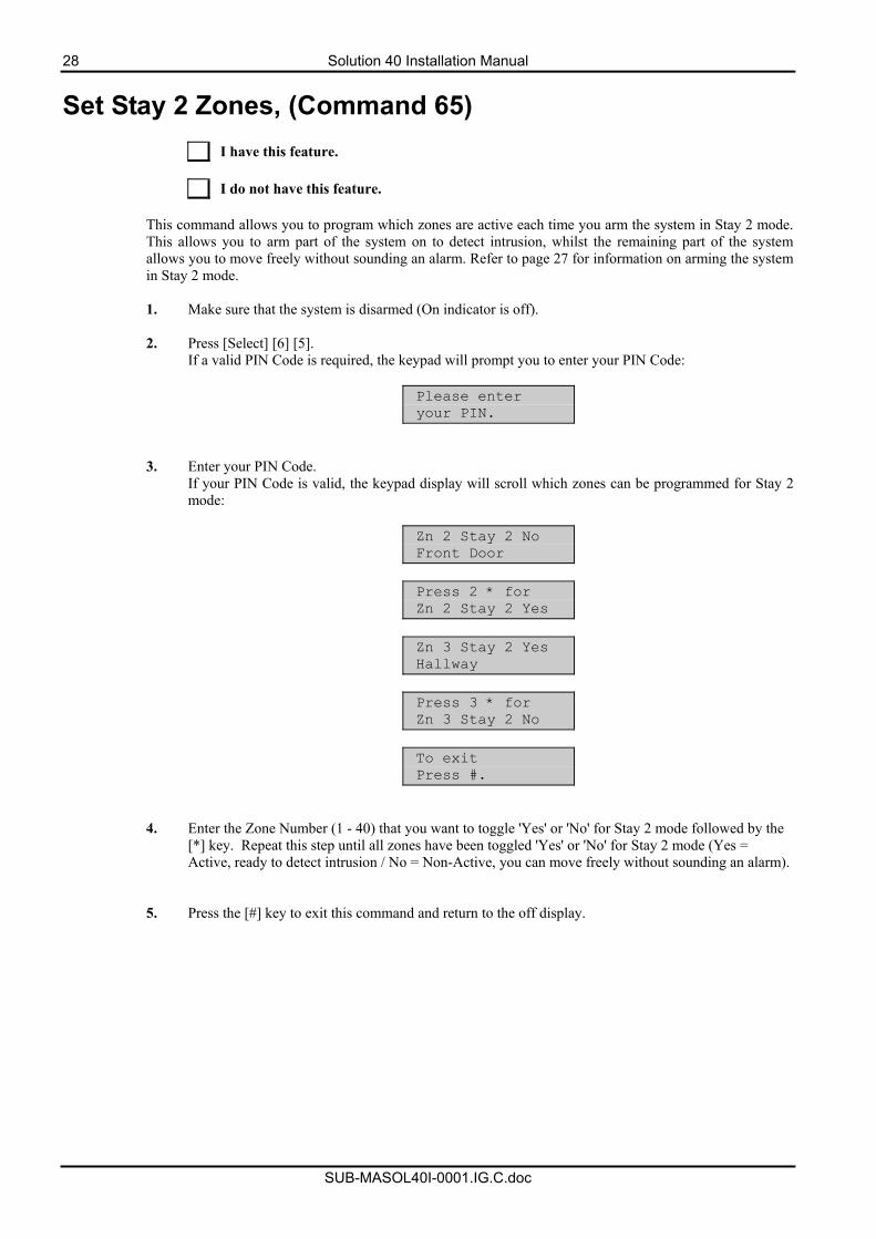
This command allows you to program which zones are active each time you arm the system in Stay 2 mode. This allows you to arm part of the system on to detect intrusion, whilst the remaining part of the system allows you to move freely without sounding an alarm. Refer to page 27 for information on arming the system in Stay 2 mode. 1. Make sure that the system is disarmed (On indicator is off).
2. Press [Select] [6] [5].
If a valid PIN Code is required, the keypad will prompt you to enter your PIN Code:
Please enter your PIN.
3. Enter your PIN Code. If your PIN Code is valid, the keypad display will scroll which zones can be programmed for Stay 2 mode:
Zn 2 Stay 2 No Front Door
Press 2 * for Zn 2 Stay 2 Yes
Zn 3 Stay 2 Yes Hallway
Press 3 * for Zn 3 Stay 2 No
To exit Press #.
4. Enter the Zone Number (1 - 40) that you want to toggle 'Yes' or 'No' for Stay 2 mode followed by the [*] key. Repeat this step until all zones have been toggled 'Yes' or 'No' for Stay 2 mode (Yes = Active, ready to detect intrusion / No = Non-Active, you can move freely without sounding an alarm).
5. Press the [#] key to exit this command and return to the off display.
Solution 40 Installation Manual 29
SUB-MASOL40I-0001.IG.C.doc
Arming The System With No Entry Delay
I have this feature. I do not have this feature.
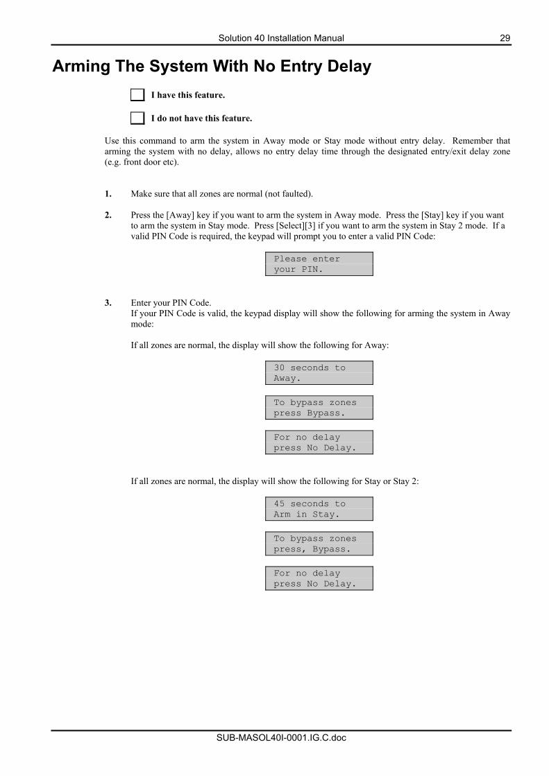
Use this command to arm the system in Away mode or Stay mode without entry delay. Remember that arming the system with no delay, allows no entry delay time through the designated entry/exit delay zone (e.g. front door etc). 1. Make sure that all zones are normal (not faulted).
2. Press the [Away] key if you want to arm the system in Away mode. Press the [Stay] key if you want
to arm the system in Stay mode. Press [Select][3] if you want to arm the system in Stay 2 mode. If a valid PIN Code is required, the keypad will prompt you to enter a valid PIN Code:
Please enter your PIN.
3. Enter your PIN Code. If your PIN Code is valid, the keypad display will show the following for arming the system in Away mode: If all zones are normal, the display will show the following for Away:
30 seconds to Away.
To bypass zones press Bypass.
For no delay press No Delay.
If all zones are normal, the display will show the following for Stay or Stay 2:
45 seconds to Arm in Stay.
To bypass zones press, Bypass.
For no delay press No Delay.
30 Solution 40 Installation Manual
SUB-MASOL40I-0001.IG.C.doc
4. To arm the system in (Away, Stay or Stay 2) modes with no entry delay, press the [No Delay] key.
5. When the system is in Away mode with no entry delay, the keypad will display the following:
Armed in Away mode
with No Delay
If the system is armed in Stay or Stay 2 mode with no entry delay, the keypad will display the following:
Armed in Stay mode
with No Delay
6. To disarm the system , enter your PIN Code.
Solution 40 Installation Manual 31
SUB-MASOL40I-0001.IG.C.doc
Arming The System With No Exit Tone (Silent Delay)
I have this feature. I do not have this feature.
This feature allows you to arm the entire system in Away or Stay mode without exit tones and at the same time, double the exit delay time.
1. Make sure that all zones are normal (not faulted).
2. Press and hold the [Away] key if you want to arm the system in Away mode with no exit tone, press
and hold the [Stay] or [2] key if you want to arm the system in Stay mode with no exit tone, or press and hold the [3] key if you want to arm the system in Stay 2 mode with no exit tone. If a valid PIN Code is required, the keypad will prompt you to enter a valid PIN Code:
Please enter your PIN.
3. Enter your PIN Code.
If your PIN Code is valid, the keypad display will show the following for Away mode:
60 seconds to Away.
To bypass zones press Bypass.
For no delay press No Delay.
If all zones are normal, the display will show the following for Stay or Stay 2:
60 seconds to Arm in Stay.
To bypass zones press, Bypass.
For no delay press No Delay.
4. To disarm the system, enter your PIN Code.
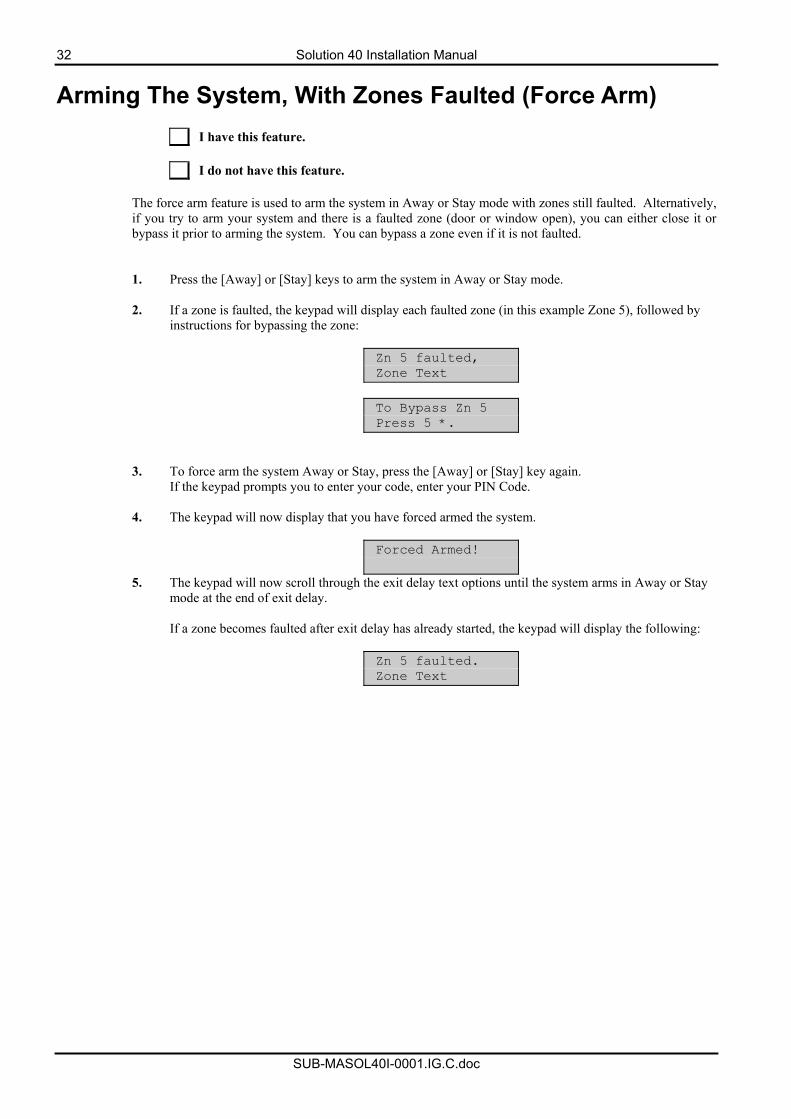
32 Solution 40 Installation Manual
SUB-MASOL40I-0001.IG.C.doc
Arming The System, With Zones Faulted (Force Arm)
I have this feature. I do not have this feature.
The force arm feature is used to arm the system in Away or Stay mode with zones still faulted. Alternatively, if you try to arm your system and there is a faulted zone (door or window open), you can either close it or bypass it prior to arming the system. You can bypass a zone even if it is not faulted. 1. Press the [Away] or [Stay] keys to arm the system in Away or Stay mode. 2. If a zone is faulted, the keypad will display each faulted zone (in this example Zone 5), followed by
instructions for bypassing the zone:
Zn 5 faulted, Zone Text
To Bypass Zn 5 Press 5 *.
3. To force arm the system Away or Stay, press the [Away] or [Stay] key again. If the keypad prompts you to enter your code, enter your PIN Code.
4. The keypad will now display that you have forced armed the system.
Forced Armed!
5. The keypad will now scroll through the exit delay text options until the system arms in Away or Stay mode at the end of exit delay.
If a zone becomes faulted after exit delay has already started, the keypad will display the following:
Zn 5 faulted. Zone Text
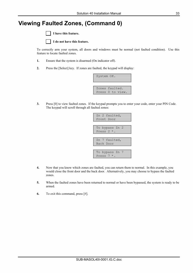
Solution 40 Installation Manual 33
SUB-MASOL40I-0001.IG.C.doc
Viewing Faulted Zones, (Command 0)
I have this feature. I do not have this feature.
To correctly arm your system, all doors and windows must be normal (not faulted condition). Use this feature to locate faulted zones. 1. Ensure that the system is disarmed (On indicator off).
2. Press the [Select] key. If zones are faulted, the keypad will display:
System OK.
Zones faulted. Press 0 to view.
3. Press [0] to view faulted zones. If the keypad prompts you to enter your code, enter your PIN Code. The keypad will scroll through all faulted zones:
Zn 2 faulted, Front Door
To bypass Zn 2 Press 2 *.
Zn 7 faulted, Back Door
To bypass Zn 7 Press 7 *.
4. Now that you know which zones are faulted, you can return them to normal. In this example, you would close the front door and the back door. Alternatively, you may choose to bypass the faulted zones.
5. When the faulted zones have been returned to normal or have been bypassed, the system is ready to be
armed.
6. To exit this command, press [#].
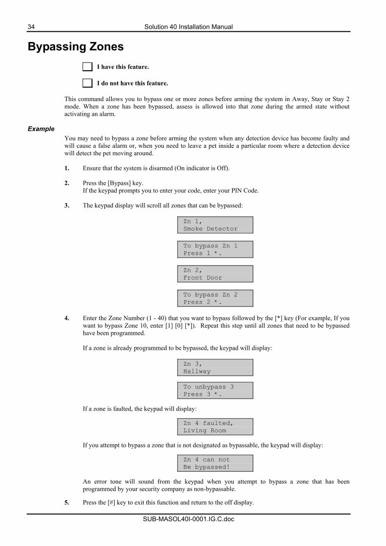
34 Solution 40 Installation Manual
SUB-MASOL40I-0001.IG.C.doc
Bypassing Zones
I have this feature. I do not have this feature.
This command allows you to bypass one or more zones before arming the system in Away, Stay or Stay 2 mode. When a zone has been bypassed, assess is allowed into that zone during the armed state without activating an alarm.
Example You may need to bypass a zone before arming the system when any detection device has become faulty and will cause a false alarm or, when you need to leave a pet inside a particular room where a detection device will detect the pet moving around.
1. Ensure that the system is disarmed (On indicator is Off).
2. Press the [Bypass] key.
If the keypad prompts you to enter your code, enter your PIN Code.
3. The keypad display will scroll all zones that can be bypassed:
Zn 1, Smoke Detector
To bypass Zn 1 Press 1 *.
Zn 2, Front Door
To bypass Zn 2 Press 2 *.
4. Enter the Zone Number (1 - 40) that you want to bypass followed by the [*] key (For example, If you
want to bypass Zone 10, enter [1] [0] [*]). Repeat this step until all zones that need to be bypassed have been programmed. If a zone is already programmed to be bypassed, the keypad will display:
Zn 3, Hallway
To unbypass 3 Press 3 *.
If a zone is faulted, the keypad will display:
Zn 4 faulted, Living Room
If you attempt to bypass a zone that is not designated as bypassable, the keypad will display:
Zn 4 can not Be bypassed!
An error tone will sound from the keypad when you attempt to bypass a zone that has been programmed by your security company as non-bypassable.
5. Press the [#] key to exit this function and return to the off display.
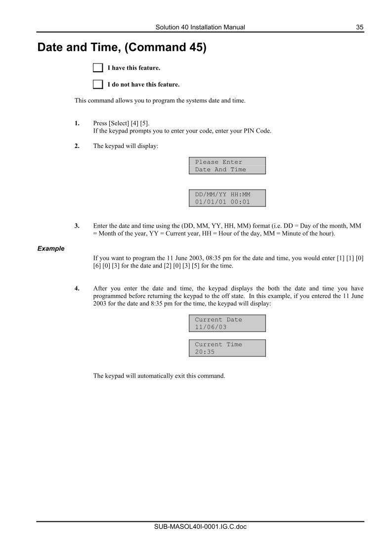
Solution 40 Installation Manual 35
SUB-MASOL40I-0001.IG.C.doc
Date and Time, (Command 45)
I have this feature. I do not have this feature.
This command allows you to program the systems date and time. 1. Press [Select] [4] [5].
If the keypad prompts you to enter your code, enter your PIN Code.
2. The keypad will display:
Please Enter Date And Time
DD/MM/YY HH:MM 01/01/01 00:01
3. Enter the date and time using the (DD, MM, YY, HH, MM) format (i.e. DD = Day of the month, MM = Month of the year, YY = Current year, HH = Hour of the day, MM = Minute of the hour).
Example
If you want to program the 11 June 2003, 08:35 pm for the date and time, you would enter [1] [1] [0] [6] [0] [3] for the date and [2] [0] [3] [5] for the time.
4. After you enter the date and time, the keypad displays the both the date and time you have programmed before returning the keypad to the off state. In this example, if you entered the 11 June 2003 for the date and 8:35 pm for the time, the keypad will display:
Current Date 11/06/03
Current Time 20:35
The keypad will automatically exit this command.
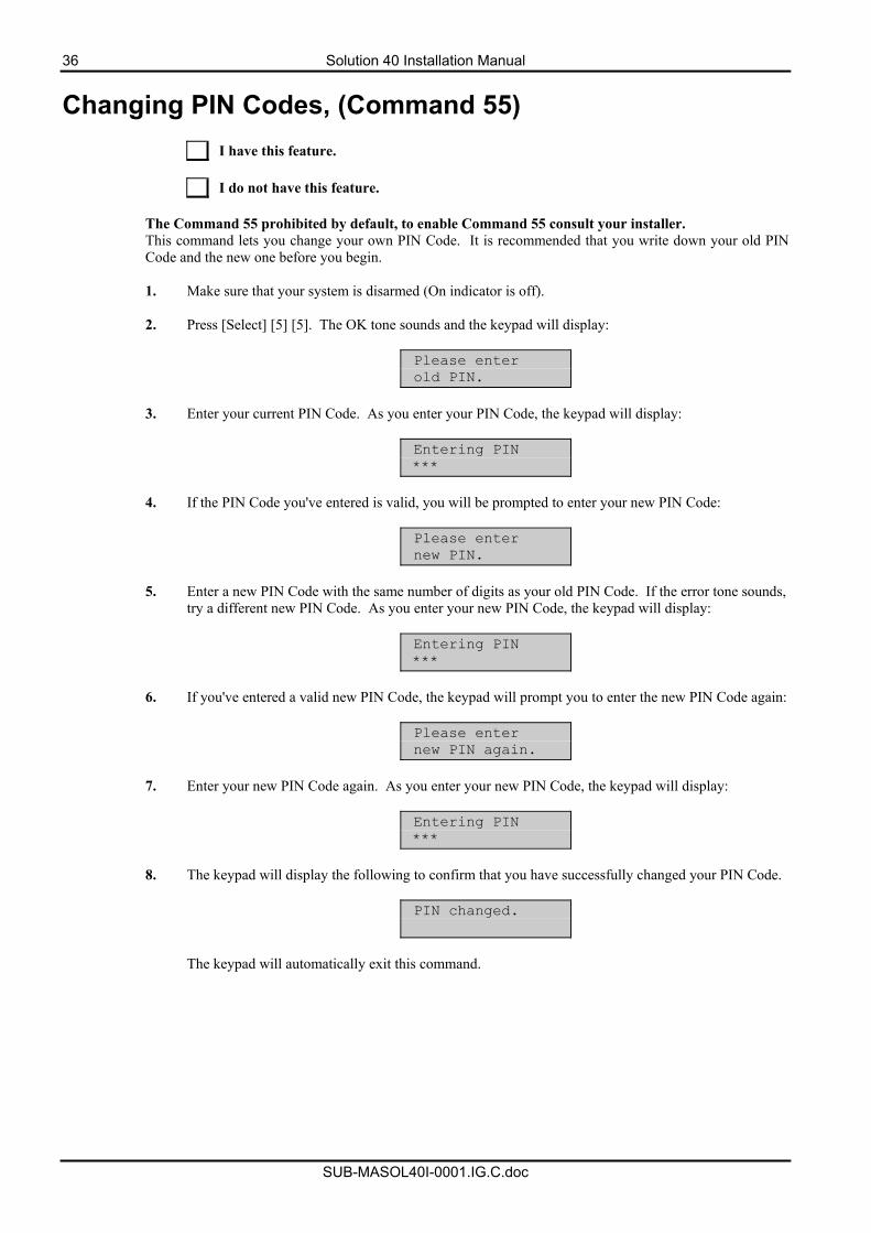
36 Solution 40 Installation Manual
SUB-MASOL40I-0001.IG.C.doc
Changing PIN Codes, (Command 55)
I have this feature. I do not have this feature.
The Command 55 prohibited by default, to enable Command 55 consult your installer. This command lets you change your own PIN Code. It is recommended that you write down your old PIN Code and the new one before you begin. 1. Make sure that your system is disarmed (On indicator is off).
2. Press [Select] [5] [5]. The OK tone sounds and the keypad will display:
Please enter old PIN.
3. Enter your current PIN Code. As you enter your PIN Code, the keypad will display:
Entering PIN ***
4. If the PIN Code you've entered is valid, you will be prompted to enter your new PIN Code:
Please enter new PIN.
5. Enter a new PIN Code with the same number of digits as your old PIN Code. If the error tone sounds,
try a different new PIN Code. As you enter your new PIN Code, the keypad will display:
Entering PIN ***
6. If you've entered a valid new PIN Code, the keypad will prompt you to enter the new PIN Code again:
Please enter new PIN again.
7. Enter your new PIN Code again. As you enter your new PIN Code, the keypad will display:
Entering PIN ***
8. The keypad will display the following to confirm that you have successfully changed your PIN Code.
PIN changed.
The keypad will automatically exit this command.
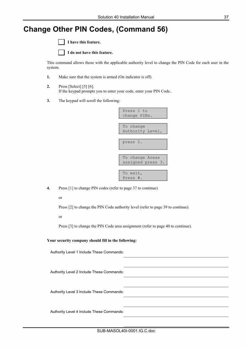
Solution 40 Installation Manual 37
SUB-MASOL40I-0001.IG.C.doc
Change Other PIN Codes, (Command 56)
I have this feature. I do not have this feature.
This command allows those with the applicable authority level to change the PIN Code for each user in the system. 1. Make sure that the system is armed (On indicator is off).
2. Press [Select] [5] [6].
If the keypad prompts you to enter your code, enter your PIN Code..
3. The keypad will scroll the following:
Press 1 to change PINs.
To change Authority Level,
press 2.
To change Areas assigned press 3.
To exit, Press #.
4. Press [1] to change PIN codes (refer to page 37 to continue)
or
Press [2] to change the PIN Code authority level (refer to page 39 to continue). or Press [3] to change the PIN Code area assignment (refer to page 40 to continue).
Your security company should fill in the following:
Authority Level 1 Include These Commands:
Authority Level 2 Include These Commands:
Authority Level 3 Include These Commands:
Authority Level 4 Include These Commands:
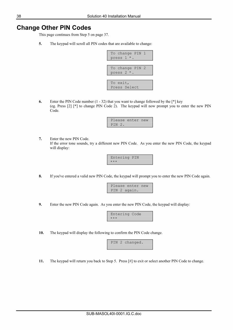
38 Solution 40 Installation Manual
SUB-MASOL40I-0001.IG.C.doc
Change Other PIN Codes This page continues from Step 5 on page 37.
5. The keypad will scroll all PIN codes that are available to change:
To change PIN 1 press 1 *.
To change PIN 2 press 2 *.
To exit, Press Select
6. Enter the PIN Code number (1 - 32) that you want to change followed by the [*] key (eg. Press [2] [*] to change PIN Code 2). The keypad will now prompt you to enter the new PIN Code.
Please enter new PIN 2.
7. Enter the new PIN Code. If the error tone sounds, try a different new PIN Code. As you enter the new PIN Code, the keypad will display:
Entering PIN ***
8. If you've entered a valid new PIN Code, the keypad will prompt you to enter the new PIN Code again.
Please enter new PIN 2 again.
9. Enter the new PIN Code again. As you enter the new PIN Code, the keypad will display:
Entering Code ***
10. The keypad will display the following to confirm the PIN Code change.
PIN 2 changed.
11. The keypad will return you back to Step 5. Press [#] to exit or select another PIN Code to change.
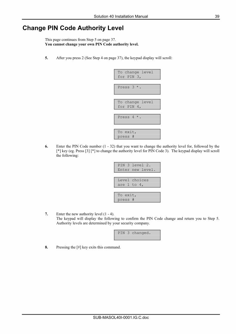
Solution 40 Installation Manual 39
SUB-MASOL40I-0001.IG.C.doc
Change PIN Code Authority Level This page continues from Step 5 on page 37. You cannot change your own PIN Code authority level. 5. After you press 2 (See Step 4 on page 37), the keypad display will scroll:
To change level for PIN 3,
Press 3 *.
To change level for PIN 4,
Press 4 *.
To exit, press #
6. Enter the PIN Code number (1 - 32) that you want to change the authority level for, followed by the
[*] key (eg. Press [3] [*] to change the authority level for PIN Code 3). The keypad display will scroll the following:
PIN 3 level 2. Enter new level.
Level choices are 1 to 4,
To exit, press #
7. Enter the new authority level (1 - 4). The keypad will display the following to confirm the PIN Code change and return you to Step 5. Authority levels are determined by your security company.
PIN 3 changed.
8. Pressing the [#] key exits this command.
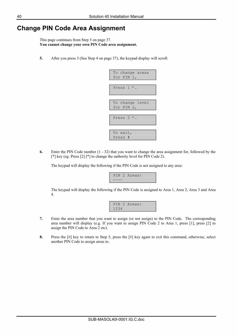
40 Solution 40 Installation Manual
SUB-MASOL40I-0001.IG.C.doc
Change PIN Code Area Assignment This page continues from Step 5 on page 37. You cannot change your own PIN Code area assignment. 5. After you press 3 (See Step 4 on page 37), the keypad display will scroll:
To change areas for PIN 1,
Press 1 *.
To change level for PIN 2,
Press 2 *.
To exit, Press #
6. Enter the PIN Code number (1 - 32) that you want to change the area assignment for, followed by the [*] key (eg. Press [2] [*] to change the authority level for PIN Code 2).
The keypad will display the following if the PIN Code is not assigned to any area:
PIN 2 Areas: ----
The keypad will display the following if the PIN Code is assigned to Area 1, Area 2, Area 3 and Area 4.
PIN 2 Areas: 1234
7. Enter the area number that you want to assign (or not assign) to the PIN Code. The corresponding
area number will display (e.g. If you want to assign PIN Code 2 to Area 1, press [1], press [2] to assign the PIN Code to Area 2 etc).
8. Press the [#] key to return to Step 5, press the [#] key again to exit this command, otherwise, select
another PIN Code to assign areas to.
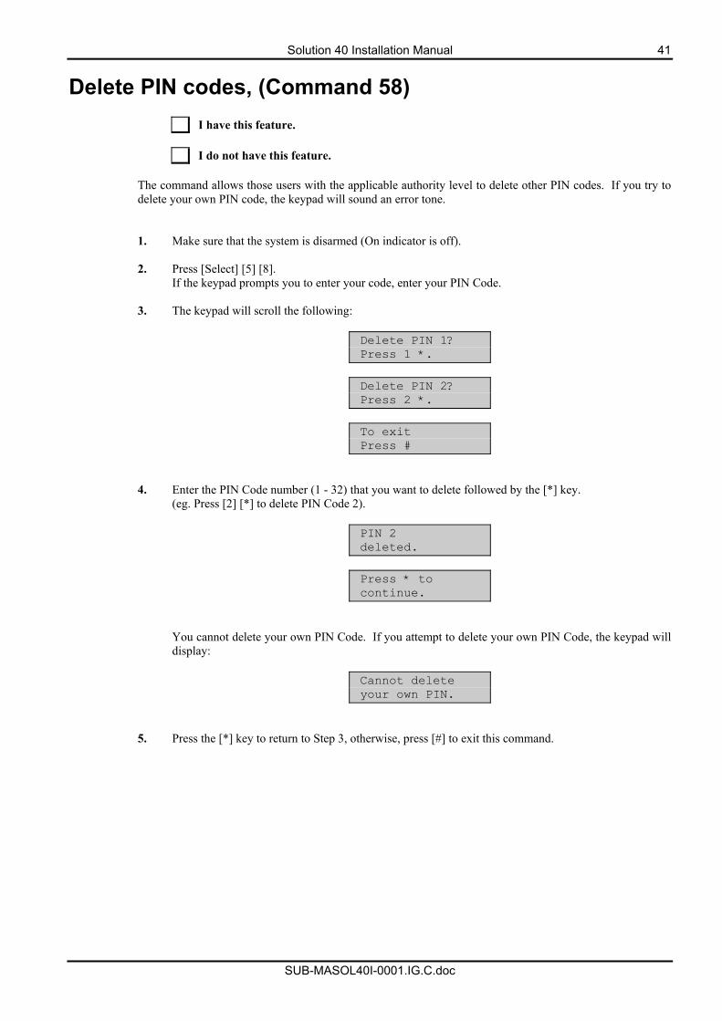
Solution 40 Installation Manual 41
SUB-MASOL40I-0001.IG.C.doc
Delete PIN codes, (Command 58)
I have this feature. I do not have this feature.
The command allows those users with the applicable authority level to delete other PIN codes. If you try to delete your own PIN code, the keypad will sound an error tone. 1. Make sure that the system is disarmed (On indicator is off).
2. Press [Select] [5] [8].
If the keypad prompts you to enter your code, enter your PIN Code.
3. The keypad will scroll the following:
Delete PIN 1? Press 1 *.
Delete PIN 2? Press 2 *.
To exit Press #
4. Enter the PIN Code number (1 - 32) that you want to delete followed by the [*] key. (eg. Press [2] [*] to delete PIN Code 2).
PIN 2 deleted.
Press * to continue.
You cannot delete your own PIN Code. If you attempt to delete your own PIN Code, the keypad will display:
Cannot delete your own PIN.
5. Press the [*] key to return to Step 3, otherwise, press [#] to exit this command.
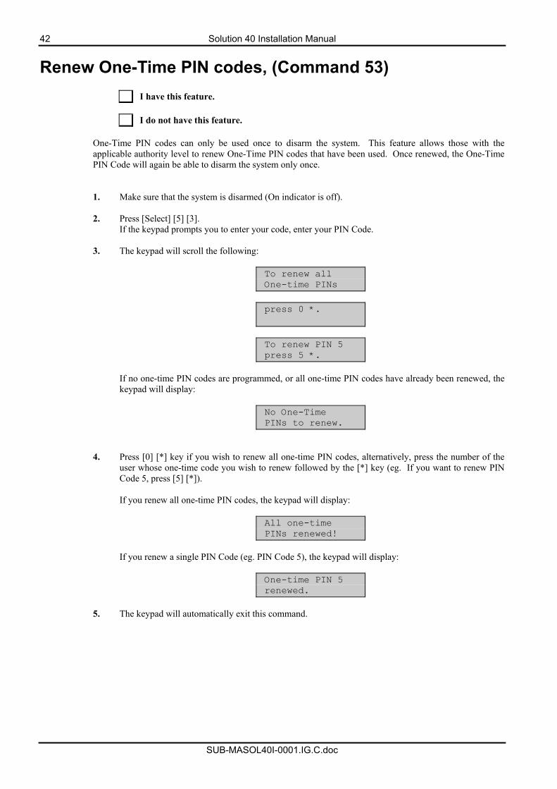
42 Solution 40 Installation Manual
SUB-MASOL40I-0001.IG.C.doc
Renew One-Time PIN codes, (Command 53)
I have this feature. I do not have this feature.
One-Time PIN codes can only be used once to disarm the system. This feature allows those with the applicable authority level to renew One-Time PIN codes that have been used. Once renewed, the One-Time PIN Code will again be able to disarm the system only once. 1. Make sure that the system is disarmed (On indicator is off).
2. Press [Select] [5] [3].
If the keypad prompts you to enter your code, enter your PIN Code.
3. The keypad will scroll the following:
To renew all One-time PINs
press 0 *.
To renew PIN 5 press 5 *.
If no one-time PIN codes are programmed, or all one-time PIN codes have already been renewed, the keypad will display:
No One-Time PINs to renew.
4. Press [0] [*] key if you wish to renew all one-time PIN codes, alternatively, press the number of the user whose one-time code you wish to renew followed by the [*] key (eg. If you want to renew PIN Code 5, press [5] [*]).
If you renew all one-time PIN codes, the keypad will display:
All one-time PINs renewed!
If you renew a single PIN Code (eg. PIN Code 5), the keypad will display:
One-time PIN 5 renewed.
5. The keypad will automatically exit this command.
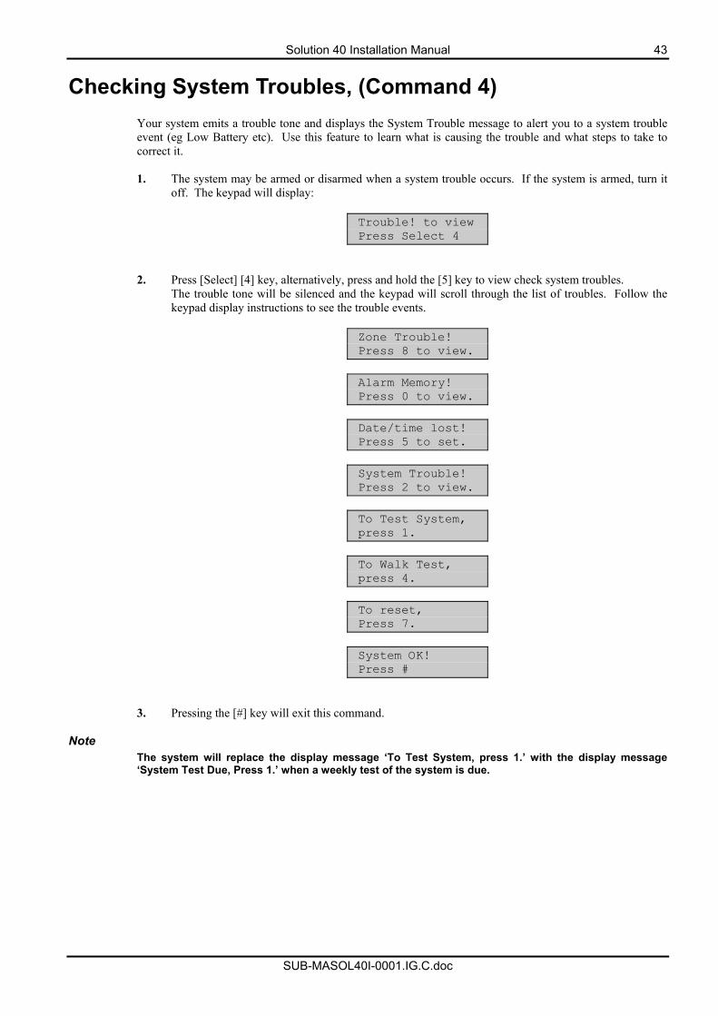
Solution 40 Installation Manual 43
SUB-MASOL40I-0001.IG.C.doc
Checking System Troubles, (Command 4) Your system emits a trouble tone and displays the System Trouble message to alert you to a system trouble event (eg Low Battery etc). Use this feature to learn what is causing the trouble and what steps to take to correct it. 1. The system may be armed or disarmed when a system trouble occurs. If the system is armed, turn it
off. The keypad will display:
Trouble! to view Press Select 4
2. Press [Select] [4] key, alternatively, press and hold the [5] key to view check system troubles. The trouble tone will be silenced and the keypad will scroll through the list of troubles. Follow the keypad display instructions to see the trouble events.
Zone Trouble! Press 8 to view.
Alarm Memory! Press 0 to view.
Date/time lost! Press 5 to set.
System Trouble! Press 2 to view.
To Test System, press 1.
To Walk Test, press 4.
To reset, Press 7.
System OK! Press #
3. Pressing the [#] key will exit this command. Note
The system will replace the display message ‘To Test System, press 1.’ with the display message ‘System Test Due, Press 1.’ when a weekly test of the system is due.
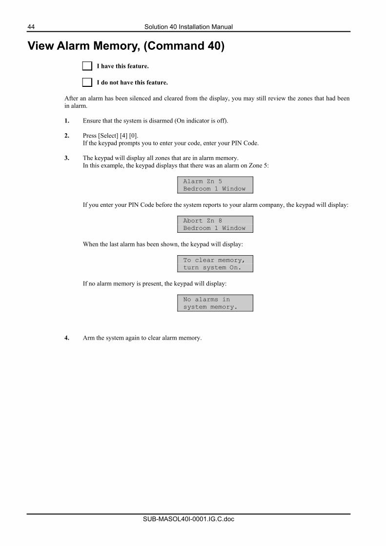
44 Solution 40 Installation Manual
SUB-MASOL40I-0001.IG.C.doc
View Alarm Memory, (Command 40)
I have this feature. I do not have this feature.
After an alarm has been silenced and cleared from the display, you may still review the zones that had been in alarm. 1. Ensure that the system is disarmed (On indicator is off).
2. Press [Select] [4] [0].
If the keypad prompts you to enter your code, enter your PIN Code.
3. The keypad will display all zones that are in alarm memory. In this example, the keypad displays that there was an alarm on Zone 5:
Alarm Zn 5 Bedroom 1 Window
If you enter your PIN Code before the system reports to your alarm company, the keypad will display:
Abort Zn 8 Bedroom 1 Window
When the last alarm has been shown, the keypad will display:
To clear memory, turn system On.
If no alarm memory is present, the keypad will display:
No alarms in system memory.
4. Arm the system again to clear alarm memory.
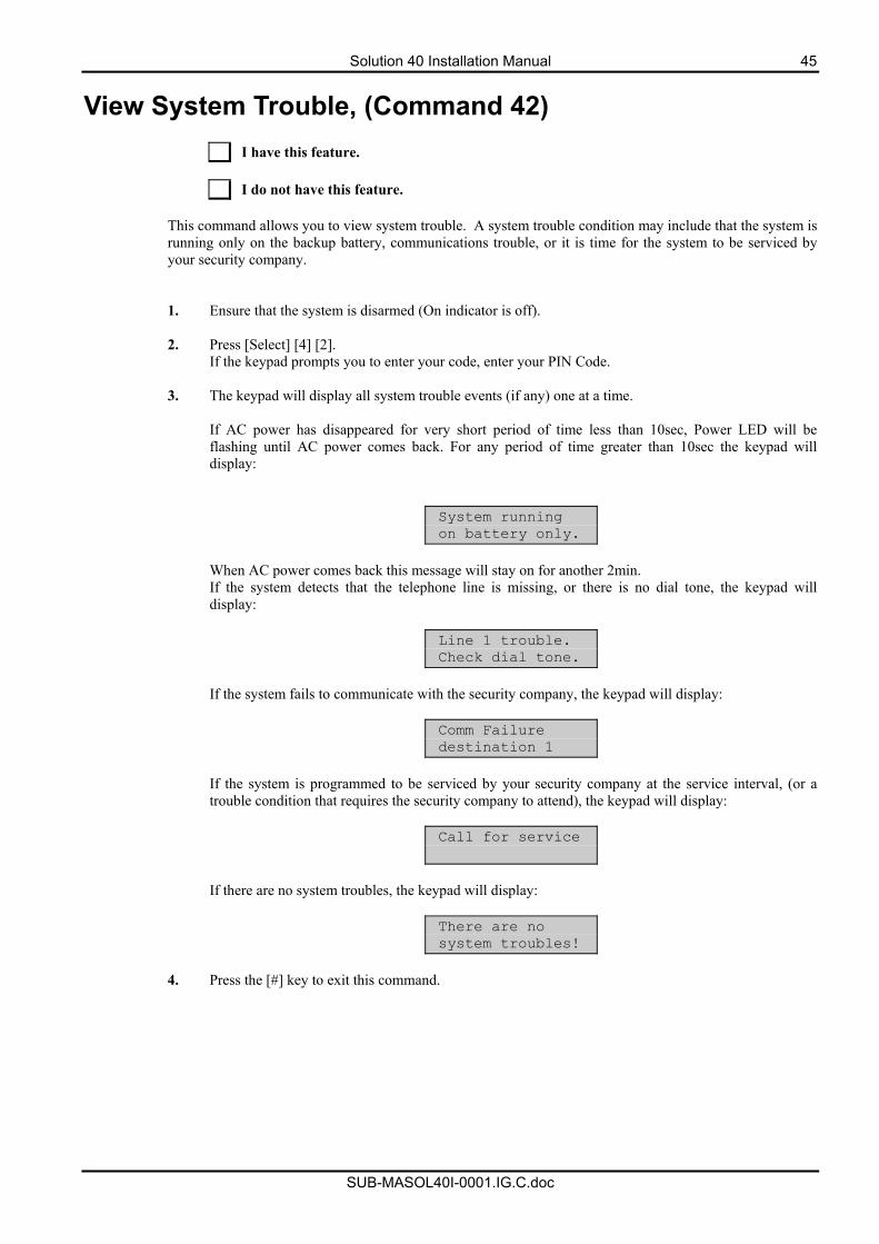
Solution 40 Installation Manual 45
SUB-MASOL40I-0001.IG.C.doc
View System Trouble, (Command 42)
I have this feature. I do not have this feature.
This command allows you to view system trouble. A system trouble condition may include that the system is running only on the backup battery, communications trouble, or it is time for the system to be serviced by your security company. 1. Ensure that the system is disarmed (On indicator is off).
2. Press [Select] [4] [2].
If the keypad prompts you to enter your code, enter your PIN Code.
3. The keypad will display all system trouble events (if any) one at a time. If AC power has disappeared for very short period of time less than 10sec, Power LED will be flashing until AC power comes back. For any period of time greater than 10sec the keypad will display:
System running on battery only.
When AC power comes back this message will stay on for another 2min. If the system detects that the telephone line is missing, or there is no dial tone, the keypad will display:
Line 1 trouble. Check dial tone.
If the system fails to communicate with the security company, the keypad will display:
Comm Failure destination 1
If the system is programmed to be serviced by your security company at the service interval, (or a trouble condition that requires the security company to attend), the keypad will display:
Call for service
If there are no system troubles, the keypad will display:
There are no system troubles!
4. Press the [#] key to exit this command.
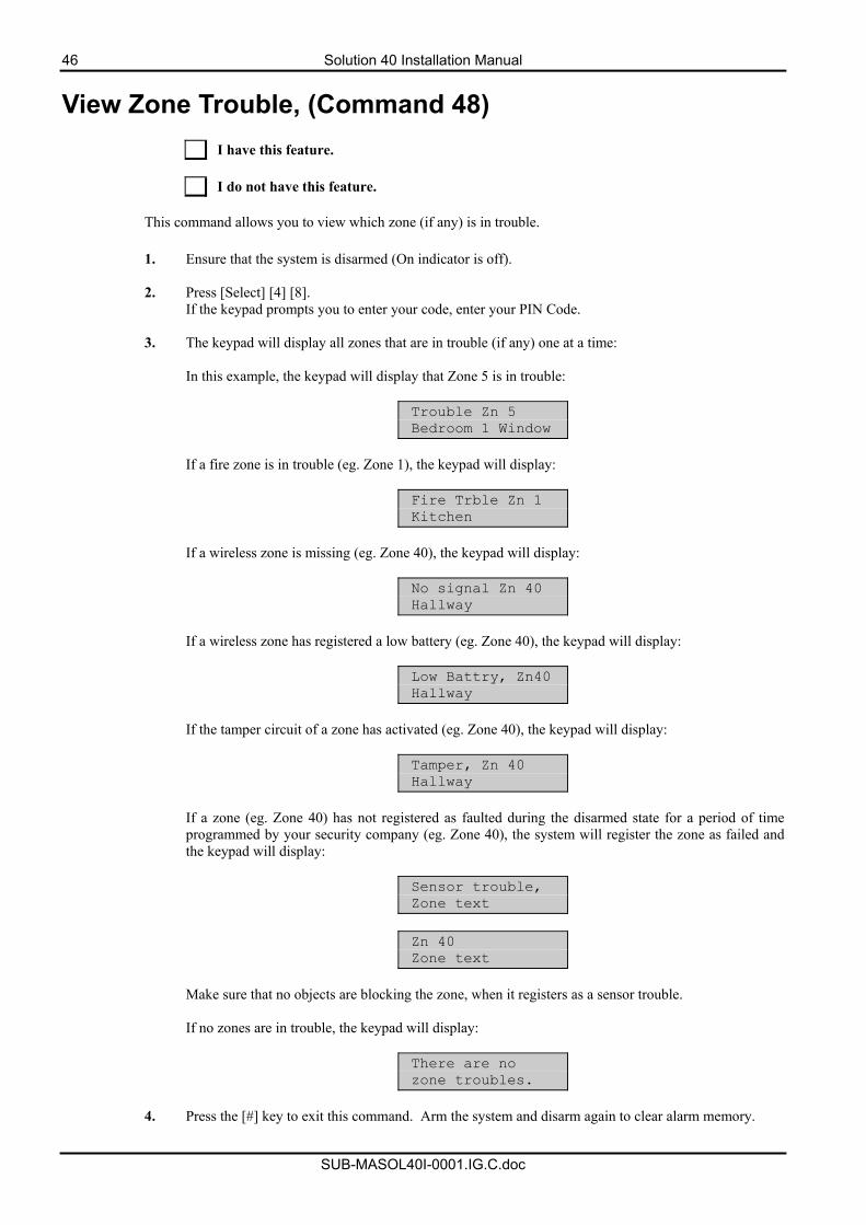
46 Solution 40 Installation Manual
SUB-MASOL40I-0001.IG.C.doc
View Zone Trouble, (Command 48)
I have this feature. I do not have this feature.
This command allows you to view which zone (if any) is in trouble.
1. Ensure that the system is disarmed (On indicator is off).
2. Press [Select] [4] [8].
If the keypad prompts you to enter your code, enter your PIN Code.
3. The keypad will display all zones that are in trouble (if any) one at a time: In this example, the keypad will display that Zone 5 is in trouble:
Trouble Zn 5 Bedroom 1 Window
If a fire zone is in trouble (eg. Zone 1), the keypad will display:
Fire Trble Zn 1 Kitchen
If a wireless zone is missing (eg. Zone 40), the keypad will display:
No signal Zn 40 Hallway
If a wireless zone has registered a low battery (eg. Zone 40), the keypad will display:
Low Battry, Zn40 Hallway
If the tamper circuit of a zone has activated (eg. Zone 40), the keypad will display:
Tamper, Zn 40 Hallway
If a zone (eg. Zone 40) has not registered as faulted during the disarmed state for a period of time programmed by your security company (eg. Zone 40), the system will register the zone as failed and the keypad will display:
Sensor trouble, Zone text
Zn 40 Zone text
Make sure that no objects are blocking the zone, when it registers as a sensor trouble. If no zones are in trouble, the keypad will display:
There are no zone troubles.
4. Press the [#] key to exit this command. Arm the system and disarm again to clear alarm memory.
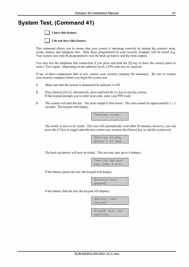
Solution 40 Installation Manual 47
SUB-MASOL40I-0001.IG.C.doc
System Test, (Command 41)
I have this feature. I do not have this feature.
This command allows you to ensure that your system is operating correctly by testing the system's siren, strobe, battery and telephone line. Only those programmed by your security company will be tested (e.g. Your system may only be programmed to test the back-up battery and the siren output). You may test the telephone line connection if you press and hold the [9] key to force the control panel to send a 'Test' report. Depending on the authority level, a PIN code may be required. If any of these components fails to test, contact your security company for assistance. Be sure to contact your security company before you begin the system test. 1. Make sure that the system is disarmed (On indicator is off).
2. Press [Select] [4] [1], alternatively, press and hold the [1] key to test the system.
If the keypad prompts you to enter your code, enter your PIN Code.
3. The system will start the test. The siren output is first tested. The siren sound for approximately 2 - 3 seconds. The keypad will display:
Testing siren.
The strobe is next to be tested. This test will automatically reset after 20 minutes, however, you can press the [*] key to toggle onto the next system test, or press the [Select] key to end the system test.
Testing strobe. press * to end
The back-up battery will now be tested. This test may take up to 4 minutes.
Testing battery may take 4 min.
If the battery passes the test, the keypad will display:
Battery test passed.
If the battery fails the test, the keypad will display:
Battery test failed!
Please call for service.
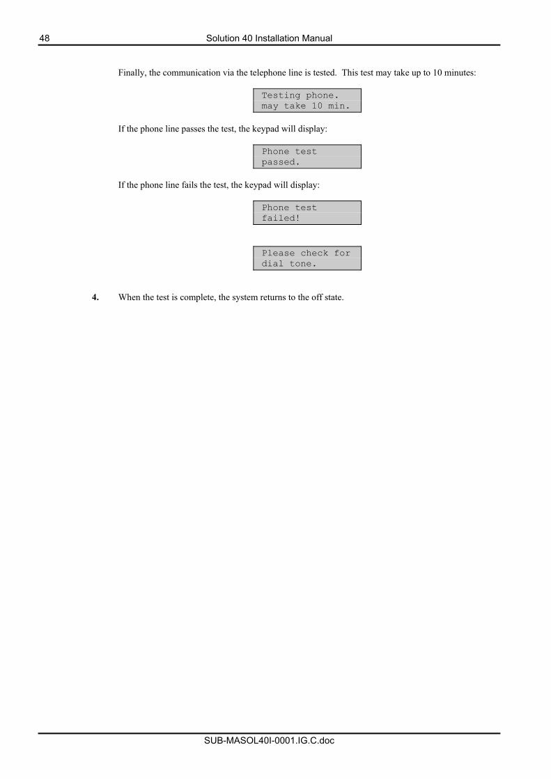
48 Solution 40 Installation Manual
SUB-MASOL40I-0001.IG.C.doc
Finally, the communication via the telephone line is tested. This test may take up to 10 minutes:
Testing phone. may take 10 min.
If the phone line passes the test, the keypad will display:
Phone test passed.
If the phone line fails the test, the keypad will display:
Phone test failed!
Please check for dial tone.
4. When the test is complete, the system returns to the off state.
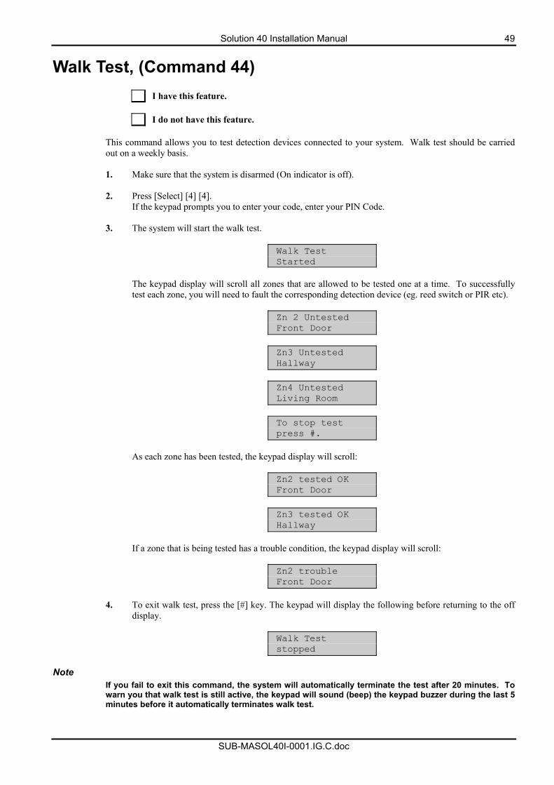
Solution 40 Installation Manual 49
SUB-MASOL40I-0001.IG.C.doc
Walk Test, (Command 44)
I have this feature. I do not have this feature.
This command allows you to test detection devices connected to your system. Walk test should be carried out on a weekly basis. 1. Make sure that the system is disarmed (On indicator is off).
2. Press [Select] [4] [4].
If the keypad prompts you to enter your code, enter your PIN Code.
3. The system will start the walk test.
Walk Test Started
The keypad display will scroll all zones that are allowed to be tested one at a time. To successfully test each zone, you will need to fault the corresponding detection device (eg. reed switch or PIR etc).
Zn 2 Untested Front Door
Zn3 Untested Hallway
Zn4 Untested Living Room
To stop test press #.
As each zone has been tested, the keypad display will scroll:
Zn2 tested OK Front Door
Zn3 tested OK Hallway
If a zone that is being tested has a trouble condition, the keypad display will scroll:
Zn2 trouble Front Door
4. To exit walk test, press the [#] key. The keypad will display the following before returning to the off
display.
Walk Test stopped
Note
If you fail to exit this command, the system will automatically terminate the test after 20 minutes. To warn you that walk test is still active, the keypad will sound (beep) the keypad buzzer during the last 5 minutes before it automatically terminates walk test.
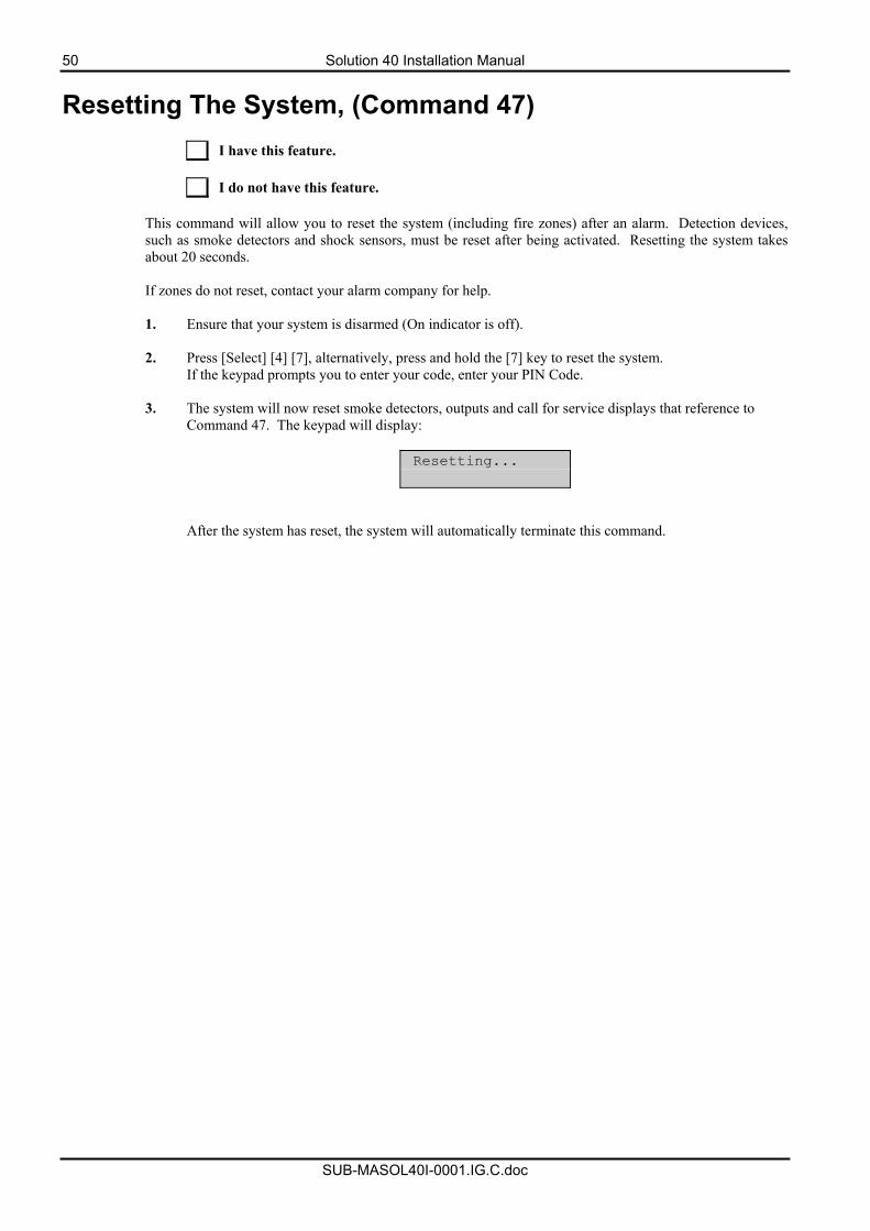
50 Solution 40 Installation Manual
SUB-MASOL40I-0001.IG.C.doc
Resetting The System, (Command 47)
I have this feature. I do not have this feature.
This command will allow you to reset the system (including fire zones) after an alarm. Detection devices, such as smoke detectors and shock sensors, must be reset after being activated. Resetting the system takes about 20 seconds. If zones do not reset, contact your alarm company for help. 1. Ensure that your system is disarmed (On indicator is off).
2. Press [Select] [4] [7], alternatively, press and hold the [7] key to reset the system.
If the keypad prompts you to enter your code, enter your PIN Code.
3. The system will now reset smoke detectors, outputs and call for service displays that reference to Command 47. The keypad will display:
Resetting...
After the system has reset, the system will automatically terminate this command.
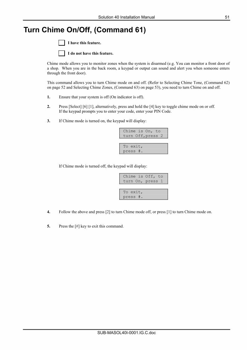
Solution 40 Installation Manual 51
SUB-MASOL40I-0001.IG.C.doc
Turn Chime On/Off, (Command 61)
I have this feature. I do not have this feature.
Chime mode allows you to monitor zones when the system is disarmed (e.g. You can monitor a front door of a shop. When you are in the back room, a keypad or output can sound and alert you when someone enters through the front door). This command allows you to turn Chime mode on and off. (Refer to Selecting Chime Tone, (Command 62) on page 52 and Selecting Chime Zones, (Command 63) on page 53), you need to turn Chime on and off. 1. Ensure that your system is off (On indicator is off).
2. Press [Select] [6] [1], alternatively, press and hold the [4] key to toggle chime mode on or off.
If the keypad prompts you to enter your code, enter your PIN Code.
3. If Chime mode is turned on, the keypad will display:
Chime is On, to turn Off,press 2
To exit, press #.
If Chime mode is turned off, the keypad will display:
Chime is Off, to turn On, press 1
To exit, press #.
4. Follow the above and press [2] to turn Chime mode off, or press [1] to turn Chime mode on.
5. Press the [#] key to exit this command.
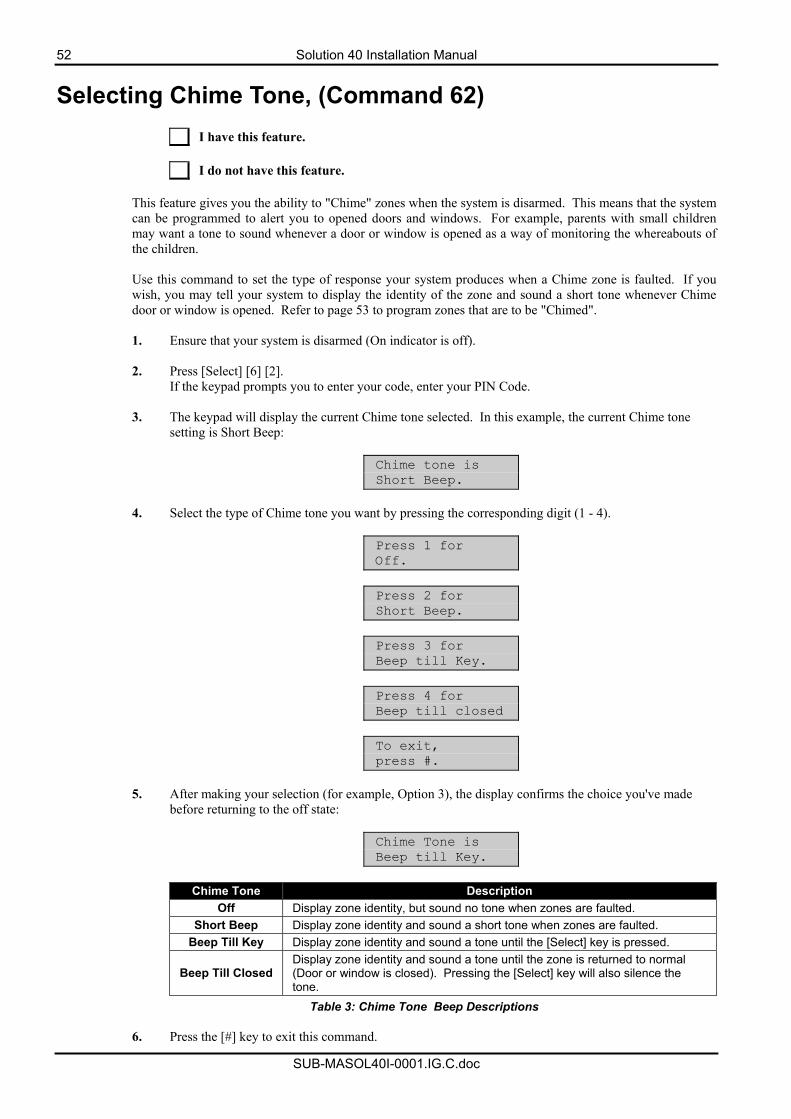
52 Solution 40 Installation Manual
SUB-MASOL40I-0001.IG.C.doc
Selecting Chime Tone, (Command 62)
I have this feature. I do not have this feature.
This feature gives you the ability to "Chime" zones when the system is disarmed. This means that the system can be programmed to alert you to opened doors and windows. For example, parents with small children may want a tone to sound whenever a door or window is opened as a way of monitoring the whereabouts of the children. Use this command to set the type of response your system produces when a Chime zone is faulted. If you wish, you may tell your system to display the identity of the zone and sound a short tone whenever Chime door or window is opened. Refer to page 53 to program zones that are to be "Chimed". 1. Ensure that your system is disarmed (On indicator is off).
2. Press [Select] [6] [2].
If the keypad prompts you to enter your code, enter your PIN Code.
3. The keypad will display the current Chime tone selected. In this example, the current Chime tone setting is Short Beep:
Chime tone is Short Beep.
4. Select the type of Chime tone you want by pressing the corresponding digit (1 - 4).
Press 1 for Off.
Press 2 for Short Beep.
Press 3 for Beep till Key.
Press 4 for Beep till closed
To exit, press #.
5. After making your selection (for example, Option 3), the display confirms the choice you've made
before returning to the off state:
Chime Tone is Beep till Key.
Chime Tone Description
Off Display zone identity, but sound no tone when zones are faulted. Short Beep Display zone identity and sound a short tone when zones are faulted.
Beep Till Key Display zone identity and sound a tone until the [Select] key is pressed.
Beep Till Closed Display zone identity and sound a tone until the zone is returned to normal (Door or window is closed). Pressing the [Select] key will also silence the tone.
Table 3: Chime Tone Beep Descriptions
6. Press the [#] key to exit this command.
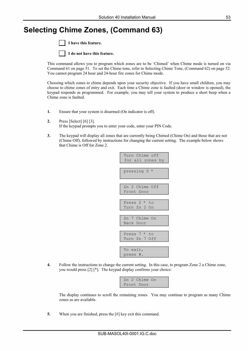
Solution 40 Installation Manual 53
SUB-MASOL40I-0001.IG.C.doc
Selecting Chime Zones, (Command 63)
I have this feature. I do not have this feature.
This command allows you to program which zones are to be ‘Chimed’ when Chime mode is turned on via Command 61 on page 51. To set the Chime tone, refer to Selecting Chime Tone, (Command 62) on page 52. You cannot program 24 hour and 24-hour fire zones for Chime mode. Choosing which zones to chime depends upon your security objective. If you have small children, you may choose to chime zones of entry and exit. Each time a Chime zone is faulted (door or window is opened), the keypad responds as programmed. For example, you may tell your system to produce a short beep when a Chime zone is faulted. 1. Ensure that your system is disarmed (On indicator is off).
2. Press [Select] [6] [3].
If the keypad prompts you to enter your code, enter your PIN Code.
3. The keypad will display all zones that are currently being Chimed (Chime On) and those that are not (Chime Off), followed by instructions for changing the current setting. The example below shows that Chime is Off for Zone 2.
Turn Chime off for all zones by
pressing 0 *
Zn 2 Chime Off Front Door
Press 2 * to Turn Zn 2 On
Zn 7 Chime On Back Door
Press 7 * to Turn Zn 7 Off
To exit, press #.
4. Follow the instructions to change the current setting. In this case, to program Zone 2 a Chime zone,
you would press [2] [*]. The keypad display confirms your choice:
Zn 2 Chime On Front Door
The display continues to scroll the remaining zones. You may continue to program as many Chime zones as are available.
5. When you are finished, press the [#] key exit this command.
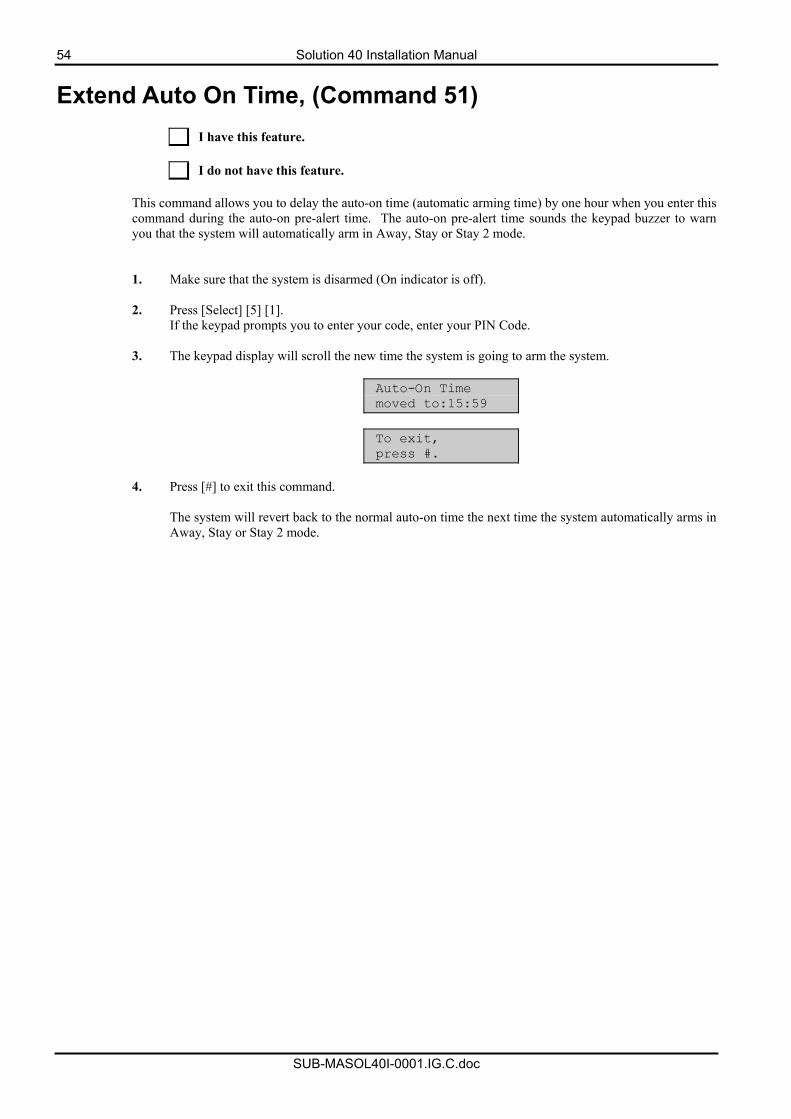
54 Solution 40 Installation Manual
SUB-MASOL40I-0001.IG.C.doc
Extend Auto On Time, (Command 51)
I have this feature. I do not have this feature.
This command allows you to delay the auto-on time (automatic arming time) by one hour when you enter this command during the auto-on pre-alert time. The auto-on pre-alert time sounds the keypad buzzer to warn you that the system will automatically arm in Away, Stay or Stay 2 mode. 1. Make sure that the system is disarmed (On indicator is off).
2. Press [Select] [5] [1].
If the keypad prompts you to enter your code, enter your PIN Code.
3. The keypad display will scroll the new time the system is going to arm the system.
Auto-On Time moved to:15:59
To exit, press #.
4. Press [#] to exit this command.
The system will revert back to the normal auto-on time the next time the system automatically arms in Away, Stay or Stay 2 mode.
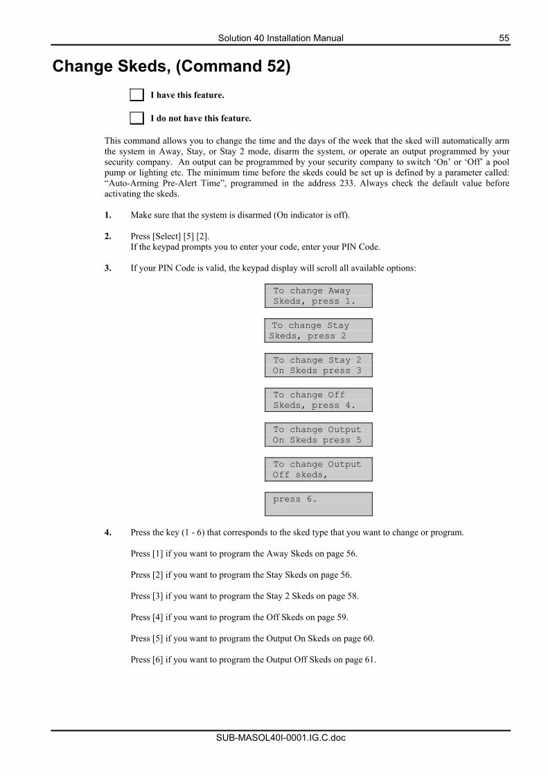
Solution 40 Installation Manual 55
SUB-MASOL40I-0001.IG.C.doc
Change Skeds, (Command 52)
I have this feature. I do not have this feature.
This command allows you to change the time and the days of the week that the sked will automatically arm the system in Away, Stay, or Stay 2 mode, disarm the system, or operate an output programmed by your security company. An output can be programmed by your security company to switch ‘On’ or ‘Off’ a pool pump or lighting etc. The minimum time before the skeds could be set up is defined by a parameter called: “Auto-Arming Pre-Alert Time”, programmed in the address 233. Always check the default value before activating the skeds. 1. Make sure that the system is disarmed (On indicator is off).
2. Press [Select] [5] [2].
If the keypad prompts you to enter your code, enter your PIN Code.
3. If your PIN Code is valid, the keypad display will scroll all available options:
To change Away Skeds, press 1.
To change Stay Skeds, press 2
To change Stay 2 On Skeds press 3
To change Off Skeds, press 4.
To change Output On Skeds press 5
To change Output Off skeds,
press 6.
4. Press the key (1 - 6) that corresponds to the sked type that you want to change or program.
Press [1] if you want to program the Away Skeds on page 56. Press [2] if you want to program the Stay Skeds on page 56. Press [3] if you want to program the Stay 2 Skeds on page 58. Press [4] if you want to program the Off Skeds on page 59. Press [5] if you want to program the Output On Skeds on page 60. Press [6] if you want to program the Output Off Skeds on page 61.
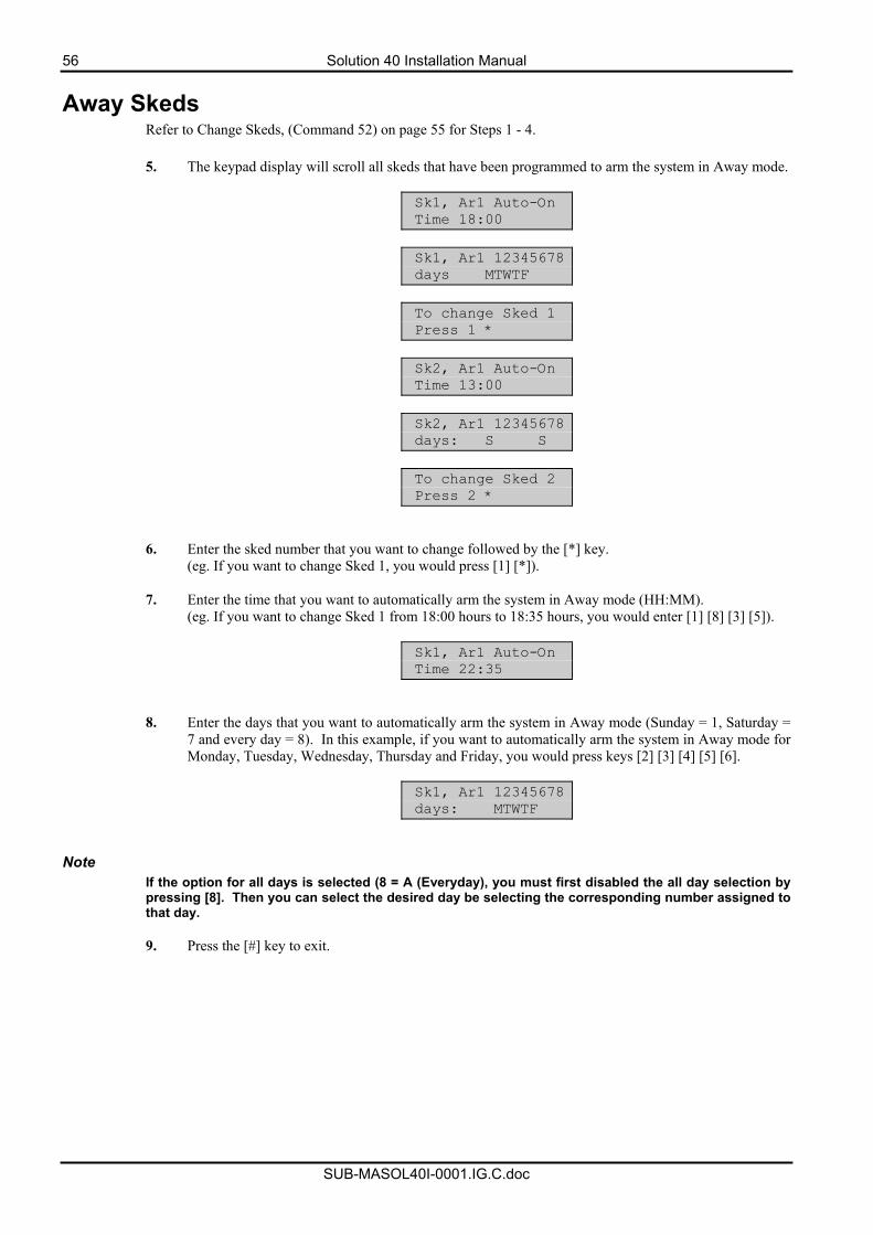
56 Solution 40 Installation Manual
SUB-MASOL40I-0001.IG.C.doc
Away Skeds Refer to Change Skeds, (Command 52) on page 55 for Steps 1 - 4.
5. The keypad display will scroll all skeds that have been programmed to arm the system in Away mode.
Sk1, Ar1 Auto-On Time 18:00
Sk1, Ar1 12345678 days MTWTF
To change Sked 1 Press 1 *
Sk2, Ar1 Auto-On Time 13:00
Sk2, Ar1 12345678 days: S S
To change Sked 2 Press 2 *
6. Enter the sked number that you want to change followed by the [*] key. (eg. If you want to change Sked 1, you would press [1] [*]).
7. Enter the time that you want to automatically arm the system in Away mode (HH:MM).
(eg. If you want to change Sked 1 from 18:00 hours to 18:35 hours, you would enter [1] [8] [3] [5]).
Sk1, Ar1 Auto-On Time 22:35
8. Enter the days that you want to automatically arm the system in Away mode (Sunday = 1, Saturday = 7 and every day = 8). In this example, if you want to automatically arm the system in Away mode for Monday, Tuesday, Wednesday, Thursday and Friday, you would press keys [2] [3] [4] [5] [6].
Sk1, Ar1 12345678 days: MTWTF
Note
If the option for all days is selected (8 = A (Everyday), you must first disabled the all day selection by pressing [8]. Then you can select the desired day be selecting the corresponding number assigned to that day. 9. Press the [#] key to exit.
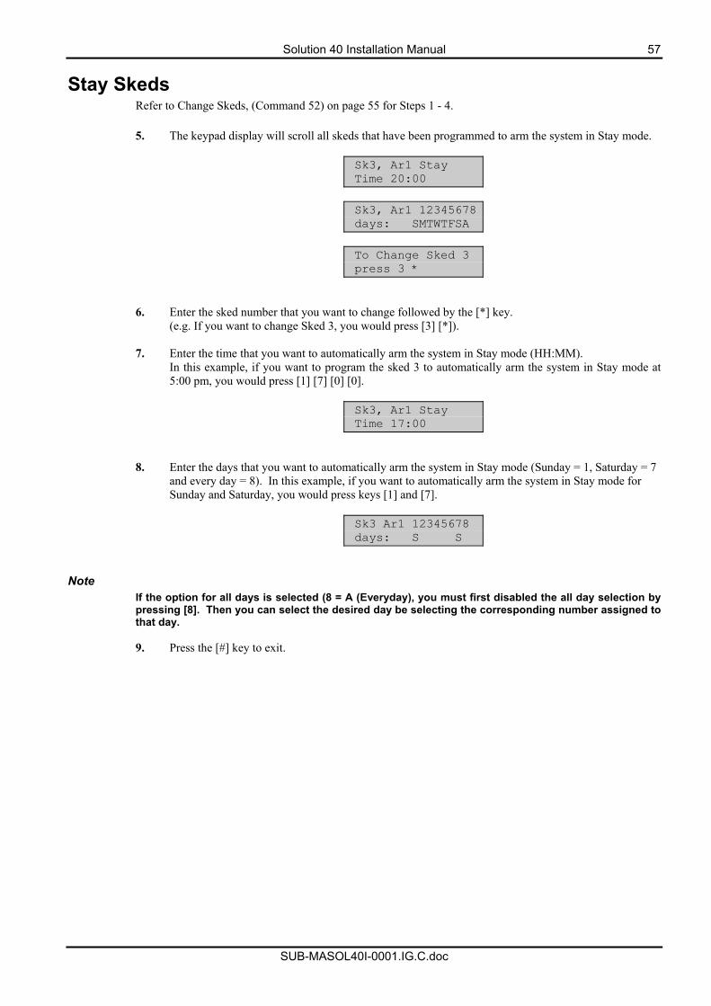
Solution 40 Installation Manual 57
SUB-MASOL40I-0001.IG.C.doc
Stay Skeds Refer to Change Skeds, (Command 52) on page 55 for Steps 1 - 4.
5. The keypad display will scroll all skeds that have been programmed to arm the system in Stay mode.
Sk3, Ar1 Stay Time 20:00
Sk3, Ar1 12345678 days: SMTWTFSA
To Change Sked 3 press 3 *
6. Enter the sked number that you want to change followed by the [*] key. (e.g. If you want to change Sked 3, you would press [3] [*]).
7. Enter the time that you want to automatically arm the system in Stay mode (HH:MM). In this example, if you want to program the sked 3 to automatically arm the system in Stay mode at 5:00 pm, you would press [1] [7] [0] [0].
Sk3, Ar1 Stay Time 17:00
8. Enter the days that you want to automatically arm the system in Stay mode (Sunday = 1, Saturday = 7 and every day = 8). In this example, if you want to automatically arm the system in Stay mode for Sunday and Saturday, you would press keys [1] and [7].
Sk3 Ar1 12345678 days: S S
Note
If the option for all days is selected (8 = A (Everyday), you must first disabled the all day selection by pressing [8]. Then you can select the desired day be selecting the corresponding number assigned to that day. 9. Press the [#] key to exit.
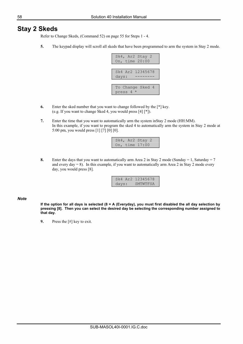
58 Solution 40 Installation Manual
SUB-MASOL40I-0001.IG.C.doc
Stay 2 Skeds Refer to Change Skeds, (Command 52) on page 55 for Steps 1 - 4.
5. The keypad display will scroll all skeds that have been programmed to arm the system in Stay 2 mode.
Sk4, Ar2 Stay 2 On, time 20:00
Sk4 Ar2 12345678 days: --------
To Change Sked 4 press 4 *
6. Enter the sked number that you want to change followed by the [*] key. (e.g. If you want to change Sked 4, you would press [4] [*]).
7. Enter the time that you want to automatically arm the system inStay 2 mode (HH:MM). In this example, if you want to program the sked 4 to automatically arm the system in Stay 2 mode at 5:00 pm, you would press [1] [7] [0] [0].
Sk4, Ar2 Stay 2 On, time 17:00
8. Enter the days that you want to automatically arm Area 2 in Stay 2 mode (Sunday = 1, Saturday = 7 and every day = 8). In this example, if you want to automatically arm Area 2 in Stay 2 mode every day, you would press [8].
Sk4 Ar2 12345678 days: SMTWTFSA
Note
If the option for all days is selected (8 = A (Everyday), you must first disabled the all day selection by pressing [8]. Then you can select the desired day be selecting the corresponding number assigned to that day. 9. Press the [#] key to exit.
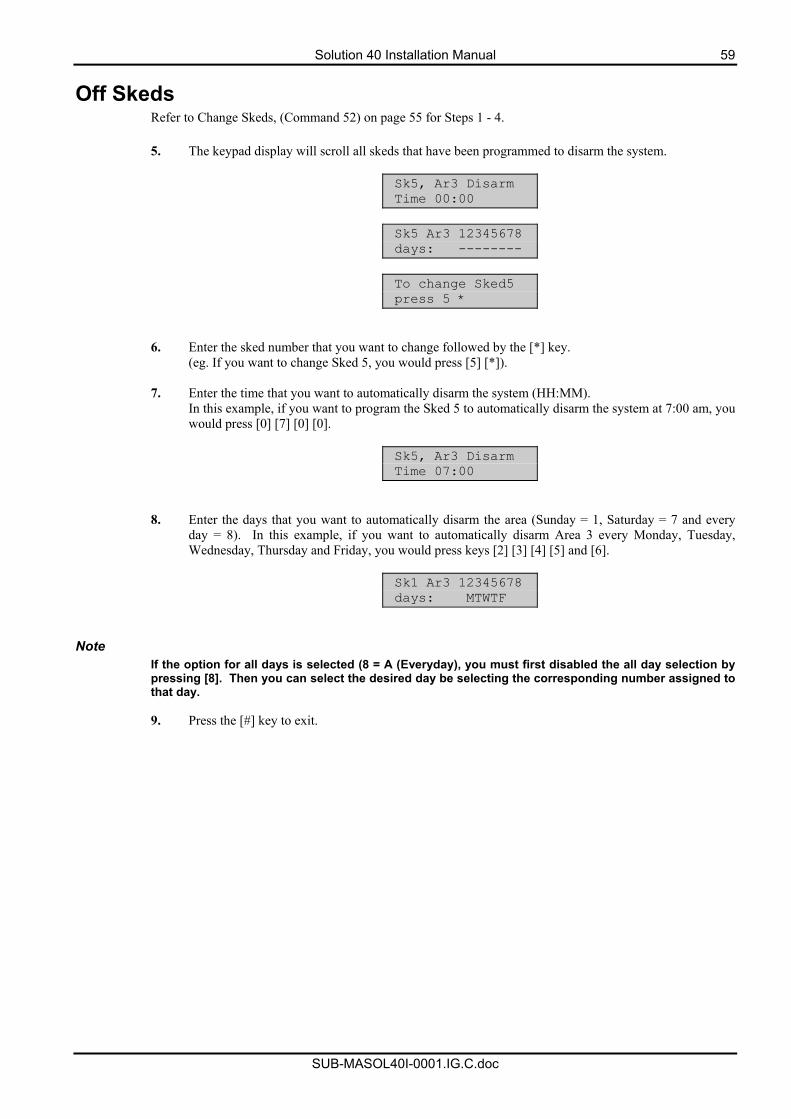
Solution 40 Installation Manual 59
SUB-MASOL40I-0001.IG.C.doc
Off Skeds Refer to Change Skeds, (Command 52) on page 55 for Steps 1 - 4.
5. The keypad display will scroll all skeds that have been programmed to disarm the system.
Sk5, Ar3 Disarm Time 00:00
Sk5 Ar3 12345678 days: --------
To change Sked5 press 5 *
6. Enter the sked number that you want to change followed by the [*] key. (eg. If you want to change Sked 5, you would press [5] [*]).
7. Enter the time that you want to automatically disarm the system (HH:MM). In this example, if you want to program the Sked 5 to automatically disarm the system at 7:00 am, you would press [0] [7] [0] [0].
Sk5, Ar3 Disarm Time 07:00
8. Enter the days that you want to automatically disarm the area (Sunday = 1, Saturday = 7 and every day = 8). In this example, if you want to automatically disarm Area 3 every Monday, Tuesday, Wednesday, Thursday and Friday, you would press keys [2] [3] [4] [5] and [6].
Sk1 Ar3 12345678 days: MTWTF
Note
If the option for all days is selected (8 = A (Everyday), you must first disabled the all day selection by pressing [8]. Then you can select the desired day be selecting the corresponding number assigned to that day. 9. Press the [#] key to exit.
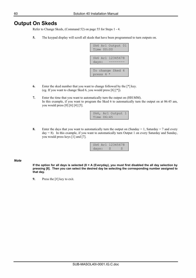
60 Solution 40 Installation Manual
SUB-MASOL40I-0001.IG.C.doc
Output On Skeds Refer to Change Skeds, (Command 52) on page 55 for Steps 1 - 4.
5. The keypad display will scroll all skeds that have been programmed to turn outputs on.
Sk6 Ar1 Output 01 Time 00:00
Sk6 Ar1 12345678 days: --------
To change Sked 6 press 6 *
6. Enter the sked number that you want to change followed by the [*] key. (eg. If you want to change Sked 6, you would press [6] [*]).
7. Enter the time that you want to automatically turn the output on (HH:MM). In this example, if you want to program the Sked 6 to automatically turn the output on at 06:45 am, you would press [0] [6] [4] [5].
Sk6, Ar1 Output 1 Time 06:45
8. Enter the days that you want to automatically turn the output on (Sunday = 1, Saturday = 7 and every day = 8). In this example, if you want to automatically turn Output 1 on every Saturday and Sunday, you would press keys [1] and [7].
Sk6 Ar1 12345678 days: S S
Note
If the option for all days is selected (8 = A (Everyday), you must first disabled the all day selection by pressing [8]. Then you can select the desired day be selecting the corresponding number assigned to that day. 9. Press the [#] key to exit.
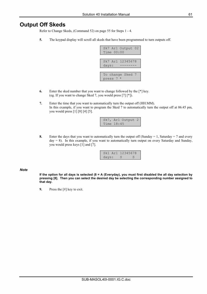
Solution 40 Installation Manual 61
SUB-MASOL40I-0001.IG.C.doc
Output Off Skeds Refer to Change Skeds, (Command 52) on page 55 for Steps 1 - 4.
5. The keypad display will scroll all skeds that have been programmed to turn outputs off.
Sk7 Ar1 Output 02 Time 00:00
Sk7 Ar1 12345678 days: --------
To change Sked 7 press 7 *
6. Enter the sked number that you want to change followed by the [*] key. (eg. If you want to change Sked 7, you would press [7] [*]).
7. Enter the time that you want to automatically turn the output off (HH:MM). In this example, if you want to program the Sked 7 to automatically turn the output off at 06:45 pm, you would press [1] [8] [4] [5].
Sk7, Ar1 Output 2 Time 18:45
8. Enter the days that you want to automatically turn the output off (Sunday = 1, Saturday = 7 and every day = 8). In this example, if you want to automatically turn output on every Saturday and Sunday, you would press keys [1] and [7].
Sk1 Ar1 12345678 days: S S
Note
If the option for all days is selected (8 = A (Everyday), you must first disabled the all day selection by pressing [8]. Then you can select the desired day be selecting the corresponding number assigned to that day. 9. Press the [#] key to exit.
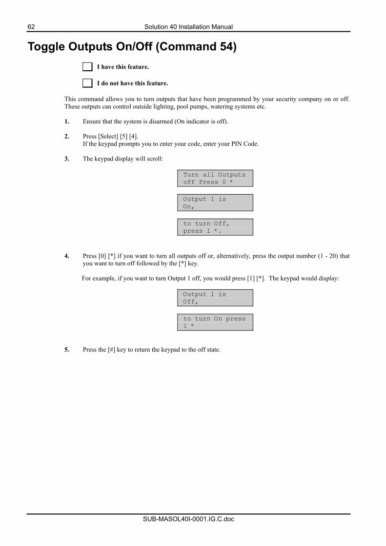
62 Solution 40 Installation Manual
SUB-MASOL40I-0001.IG.C.doc
Toggle Outputs On/Off (Command 54)
I have this feature. I do not have this feature.
This command allows you to turn outputs that have been programmed by your security company on or off. These outputs can control outside lighting, pool pumps, watering systems etc. 1. Ensure that the system is disarmed (On indicator is off).
2. Press [Select] [5] [4].
If the keypad prompts you to enter your code, enter your PIN Code.
3. The keypad display will scroll:
Turn all Outputs off Press 0 *
Output 1 is On,
to turn Off, press 1 *.
4. Press [0] [*] if you want to turn all outputs off or, alternatively, press the output number (1 - 20) that you want to turn off followed by the [*] key.
For example, if you want to turn Output 1 off, you would press [1] [*]. The keypad would display:
Output 1 is Off,
to turn On press 1 *
5. Press the [#] key to return the keypad to the off state.
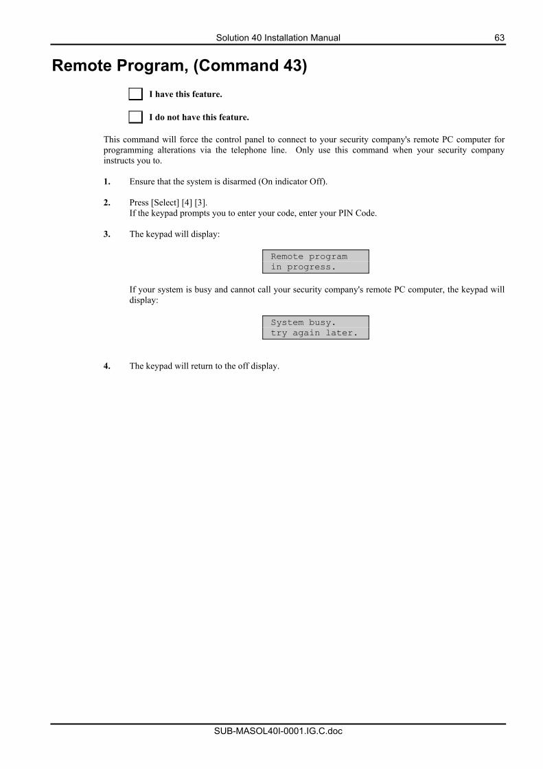
Solution 40 Installation Manual 63
SUB-MASOL40I-0001.IG.C.doc
Remote Program, (Command 43)
I have this feature. I do not have this feature.
This command will force the control panel to connect to your security company's remote PC computer for programming alterations via the telephone line. Only use this command when your security company instructs you to. 1. Ensure that the system is disarmed (On indicator Off).
2. Press [Select] [4] [3].
If the keypad prompts you to enter your code, enter your PIN Code.
3. The keypad will display:
Remote program in progress.
If your system is busy and cannot call your security company's remote PC computer, the keypad will display:
System busy. try again later.
4. The keypad will return to the off display.
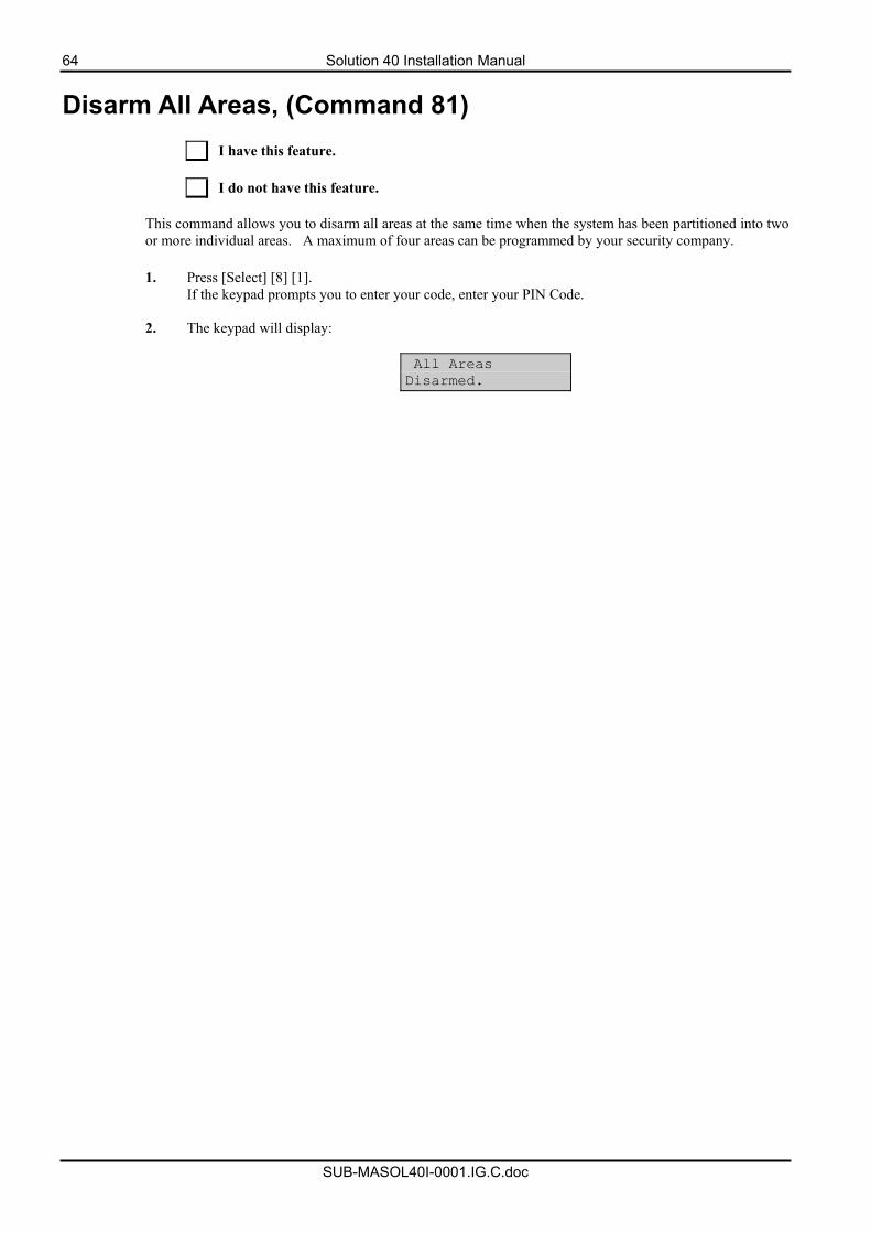
64 Solution 40 Installation Manual
SUB-MASOL40I-0001.IG.C.doc
Disarm All Areas, (Command 81)
I have this feature. I do not have this feature.
This command allows you to disarm all areas at the same time when the system has been partitioned into two or more individual areas. A maximum of four areas can be programmed by your security company.
1. Press [Select] [8] [1].
If the keypad prompts you to enter your code, enter your PIN Code.
2. The keypad will display:
All Areas Disarmed.
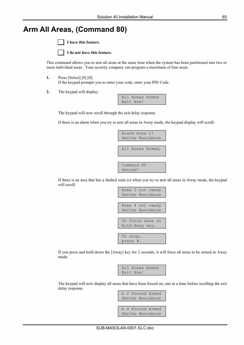
Solution 40 Installation Manual 65
SUB-MASOL40I-0001.IG.C.doc
Arm All Areas, (Command 80)
I have this feature. I do not have this feature.
This command allows you to arm all areas at the same time when the system has been partitioned into two or more individual areas. Your security company can program a maximum of four areas.
1. Press [Select] [8] [0].
If the keypad prompts you to enter your code, enter your PIN Code.
2. The keypad will display: All Areas Armed Exit Now!
The keypad will now scroll through the exit delay response If there is an alarm when you try to arm all areas in Away mode, the keypad display will scroll:
Alarm Area 1! Smiths Residence
All Areas Armed,
Command 80 Denied!
If there is an area that has a faulted zone (s) when you try to arm all areas in Away mode, the keypad will scroll:
Area 2 not ready Smiths Residence
Area 4 not ready Smiths Residence
To force area on hold Away key.
To stop, press #.
If you press and hold down the [Away] key for 2 seconds, it will force all areas to be armed in Away mode.
All Areas Armed Exit Now!
The keypad will now display all areas that have been forced on, one at a time before scrolling the exit delay response.
A 2 Forced Armed Smiths Residence
A 4 Forced Armed Smiths Residence
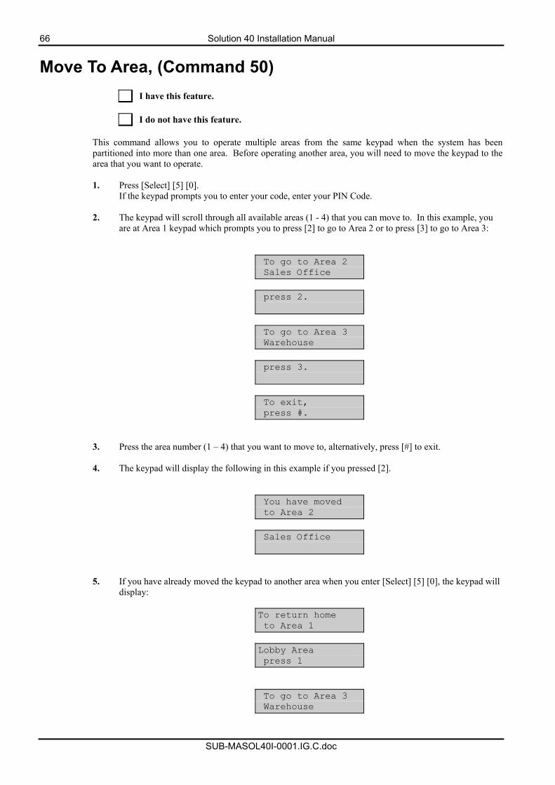
66 Solution 40 Installation Manual
SUB-MASOL40I-0001.IG.C.doc
Move To Area, (Command 50)
I have this feature. I do not have this feature.
This command allows you to operate multiple areas from the same keypad when the system has been partitioned into more than one area. Before operating another area, you will need to move the keypad to the area that you want to operate. 1. Press [Select] [5] [0].
If the keypad prompts you to enter your code, enter your PIN Code.
2. The keypad will scroll through all available areas (1 - 4) that you can move to. In this example, you are at Area 1 keypad which prompts you to press [2] to go to Area 2 or to press [3] to go to Area 3:
To go to Area 2 Sales Office
press 2.
To go to Area 3 Warehouse
press 3.
To exit, press #.
3. Press the area number (1 – 4) that you want to move to, alternatively, press [#] to exit.
4. The keypad will display the following in this example if you pressed [2].
You have moved to Area 2
Sales Office
5. If you have already moved the keypad to another area when you enter [Select] [5] [0], the keypad will display:
To return home to Area 1
Lobby Area press 1
To go to Area 3 Warehouse
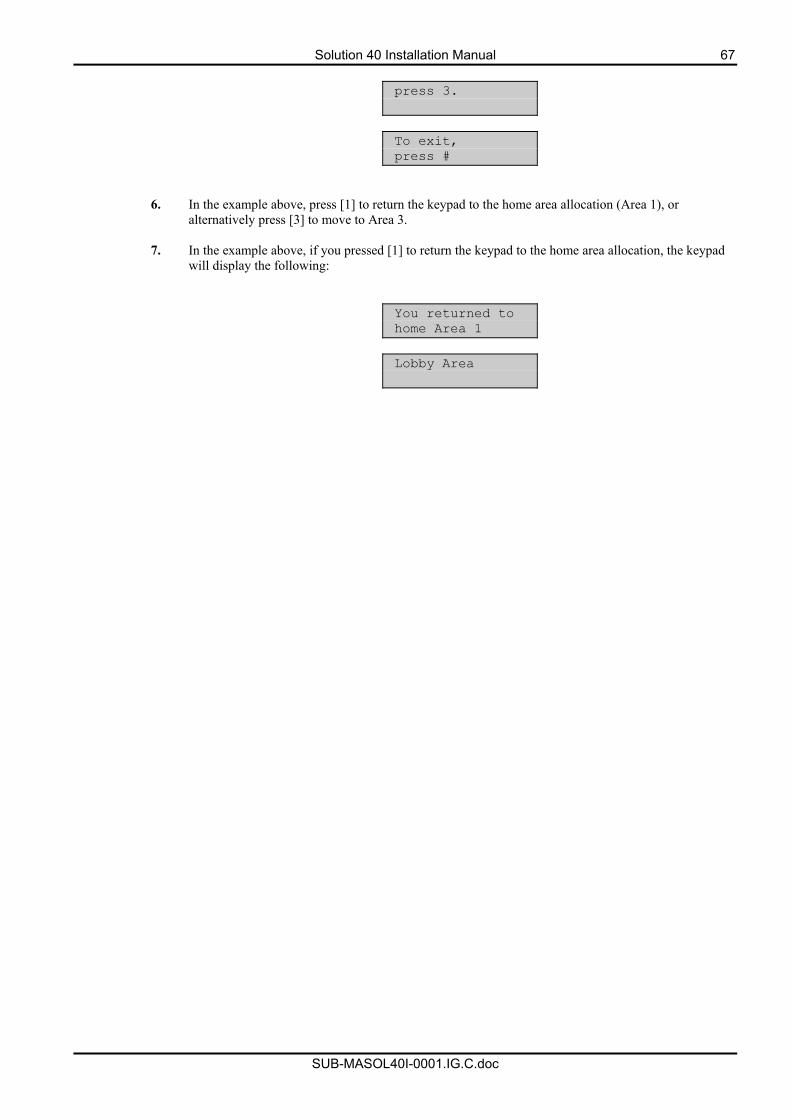
Solution 40 Installation Manual 67
SUB-MASOL40I-0001.IG.C.doc
press 3.
To exit, press #
6. In the example above, press [1] to return the keypad to the home area allocation (Area 1), or alternatively press [3] to move to Area 3.
7. In the example above, if you pressed [1] to return the keypad to the home area allocation, the keypad
will display the following:
You returned to home Area 1
Lobby Area
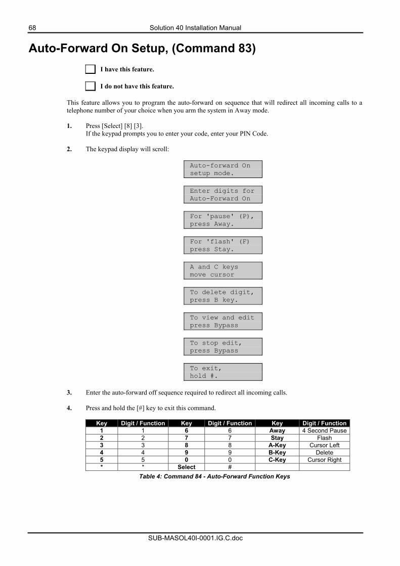
68 Solution 40 Installation Manual
SUB-MASOL40I-0001.IG.C.doc
Auto-Forward On Setup, (Command 83)
I have this feature. I do not have this feature.
This feature allows you to program the auto-forward on sequence that will redirect all incoming calls to a telephone number of your choice when you arm the system in Away mode. 1. Press [Select] [8] [3].
If the keypad prompts you to enter your code, enter your PIN Code.
2. The keypad display will scroll:
Auto-forward On setup mode.
Enter digits for Auto-Forward On
For 'pause' (P), press Away.
For 'flash' (F) press Stay.
A and C keys move cursor
To delete digit, press B key.
To view and edit press Bypass
To stop edit, press Bypass
To exit, hold #.
3. Enter the auto-forward off sequence required to redirect all incoming calls.
4. Press and hold the [#] key to exit this command.
Key Digit / Function Key Digit / Function Key Digit / Function
1 1 6 6 Away 4 Second Pause2 2 7 7 Stay Flash 3 3 8 8 A-Key Cursor Left 4 4 9 9 B-Key Delete 5 5 0 0 C-Key Cursor Right * * Select #
Table 4: Command 84 - Auto-Forward Function Keys
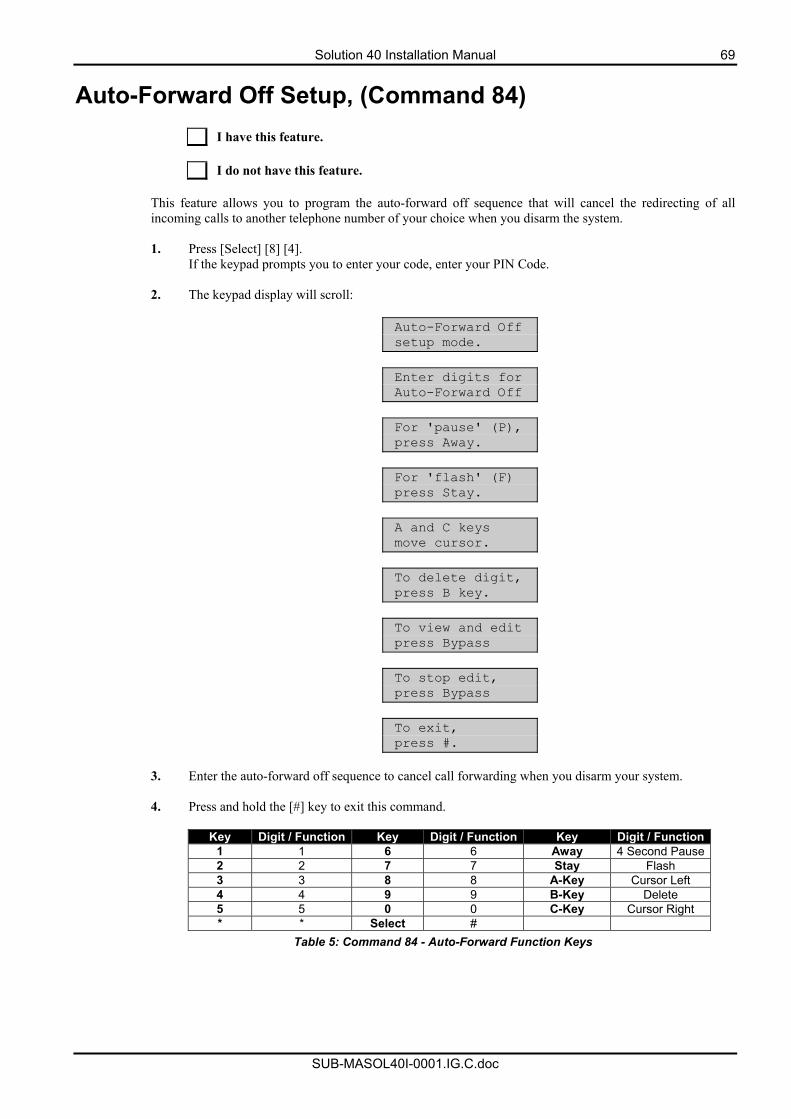
Solution 40 Installation Manual 69
SUB-MASOL40I-0001.IG.C.doc
Auto-Forward Off Setup, (Command 84)
I have this feature. I do not have this feature.
This feature allows you to program the auto-forward off sequence that will cancel the redirecting of all incoming calls to another telephone number of your choice when you disarm the system. 1. Press [Select] [8] [4].
If the keypad prompts you to enter your code, enter your PIN Code.
2. The keypad display will scroll:
Auto-Forward Off setup mode.
Enter digits for Auto-Forward Off
For 'pause' (P), press Away.
For 'flash' (F) press Stay.
A and C keys move cursor.
To delete digit, press B key.
To view and edit press Bypass
To stop edit, press Bypass
To exit, press #.
3. Enter the auto-forward off sequence to cancel call forwarding when you disarm your system.
4. Press and hold the [#] key to exit this command.
Key Digit / Function Key Digit / Function Key Digit / Function
1 1 6 6 Away 4 Second Pause2 2 7 7 Stay Flash 3 3 8 8 A-Key Cursor Left 4 4 9 9 B-Key Delete 5 5 0 0 C-Key Cursor Right * * Select #
Table 5: Command 84 - Auto-Forward Function Keys
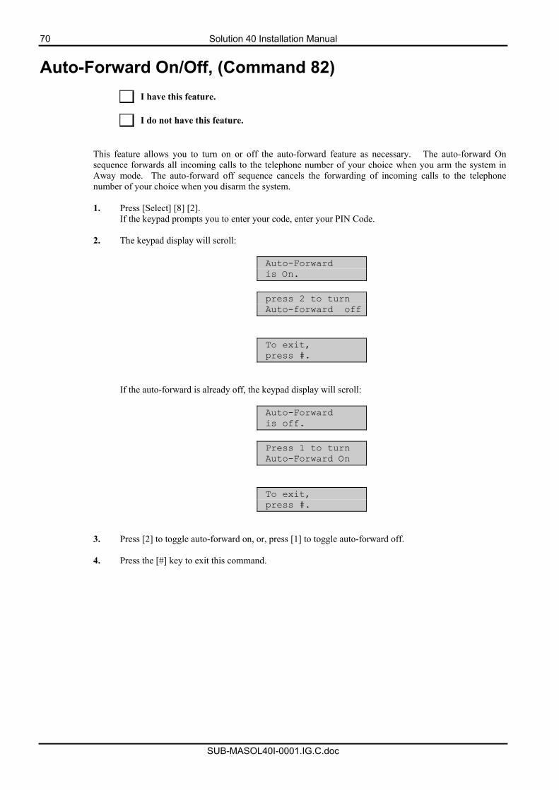
70 Solution 40 Installation Manual
SUB-MASOL40I-0001.IG.C.doc
Auto-Forward On/Off, (Command 82)
I have this feature. I do not have this feature.
This feature allows you to turn on or off the auto-forward feature as necessary. The auto-forward On sequence forwards all incoming calls to the telephone number of your choice when you arm the system in Away mode. The auto-forward off sequence cancels the forwarding of incoming calls to the telephone number of your choice when you disarm the system. 1. Press [Select] [8] [2].
If the keypad prompts you to enter your code, enter your PIN Code.
2. The keypad display will scroll:
Auto-Forward is On.
press 2 to turn Auto-forward off
To exit, press #.
If the auto-forward is already off, the keypad display will scroll:
Auto-Forward is off.
Press 1 to turn Auto-Forward On
To exit, press #.
3. Press [2] to toggle auto-forward on, or, press [1] to toggle auto-forward off.
4. Press the [#] key to exit this command.
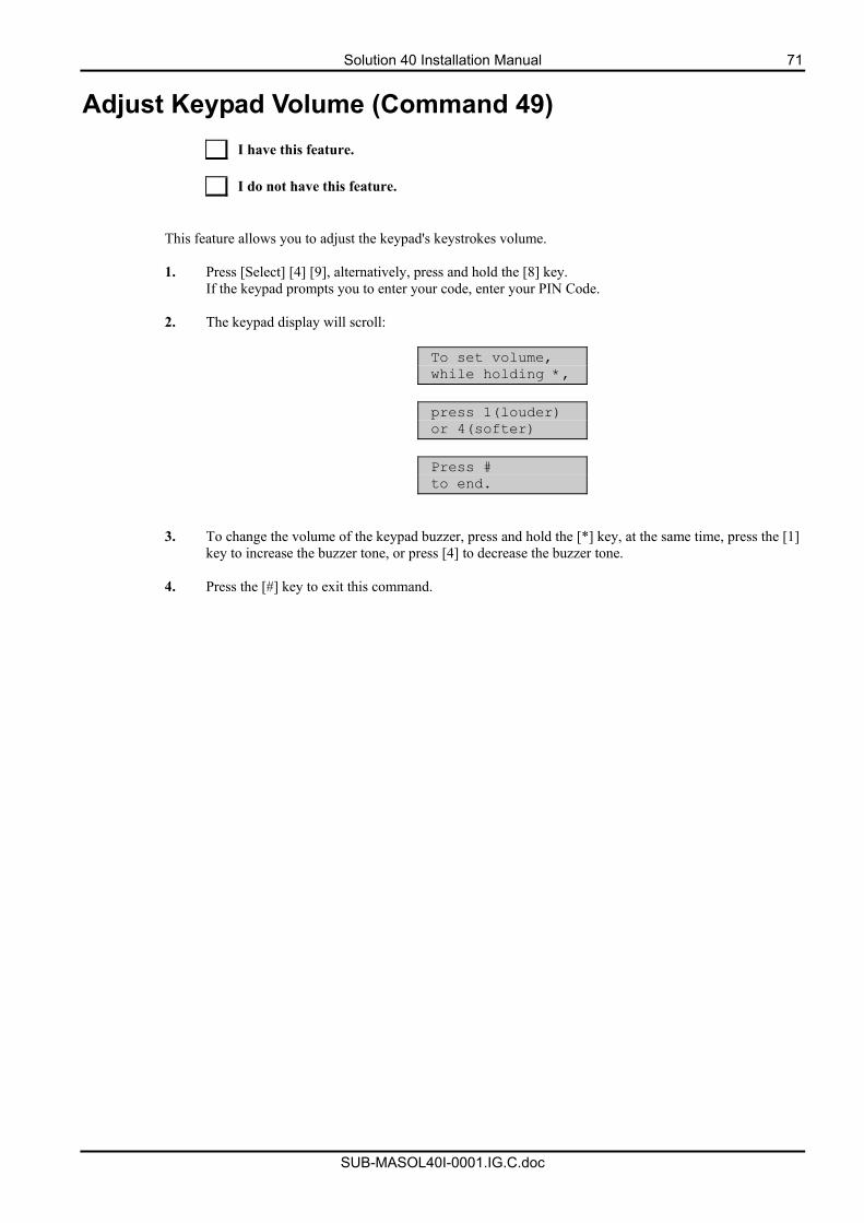
Solution 40 Installation Manual 71
SUB-MASOL40I-0001.IG.C.doc
Adjust Keypad Volume (Command 49)
I have this feature. I do not have this feature.
This feature allows you to adjust the keypad's keystrokes volume. 1. Press [Select] [4] [9], alternatively, press and hold the [8] key.
If the keypad prompts you to enter your code, enter your PIN Code.
2. The keypad display will scroll:
To set volume, while holding *,
press 1(louder) or 4(softer)
Press # to end.
3. To change the volume of the keypad buzzer, press and hold the [*] key, at the same time, press the [1] key to increase the buzzer tone, or press [4] to decrease the buzzer tone.
4. Press the [#] key to exit this command.
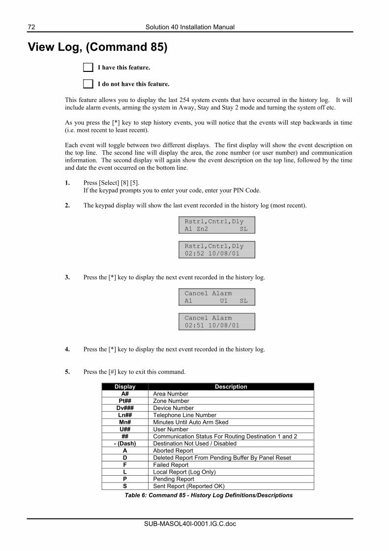
72 Solution 40 Installation Manual
SUB-MASOL40I-0001.IG.C.doc
View Log, (Command 85)
I have this feature. I do not have this feature.
This feature allows you to display the last 254 system events that have occurred in the history log. It will include alarm events, arming the system in Away, Stay and Stay 2 mode and turning the system off etc. As you press the [*] key to step history events, you will notice that the events will step backwards in time (i.e. most recent to least recent). Each event will toggle between two different displays. The first display will show the event description on the top line. The second line will display the area, the zone number (or user number) and communication information. The second display will again show the event description on the top line, followed by the time and date the event occurred on the bottom line. 1. Press [Select] [8] [5].
If the keypad prompts you to enter your code, enter your PIN Code.
2. The keypad display will show the last event recorded in the history log (most recent).
Rstrl,Cntrl,Dly A1 Zn2 SL
Rstrl,Cntrl,Dly 02:52 10/08/01
3. Press the [*] key to display the next event recorded in the history log.
Cancel Alarm A1 U1 SL
Cancel Alarm 02:51 10/08/01
4. Press the [*] key to display the next event recorded in the history log. 5. Press the [#] key to exit this command.
Display Description A# Area Number
Pt## Zone Number Dv### Device Number Ln## Telephone Line Number Mn# Minutes Until Auto Arm Sked U## User Number ## Communication Status For Routing Destination 1 and 2
- (Dash) Destination Not Used / Disabled A Aborted Report D Deleted Report From Pending Buffer By Panel Reset F Failed Report L Local Report (Log Only) P Pending Report S Sent Report (Reported OK) Table 6: Command 85 - History Log Definitions/Descriptions
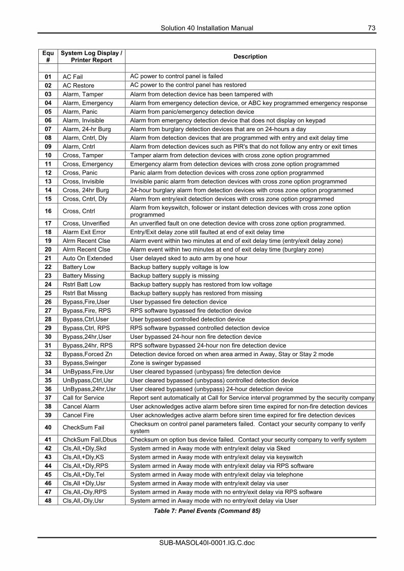
Solution 40 Installation Manual 73
SUB-MASOL40I-0001.IG.C.doc
Equ #
System Log Display / Printer Report Description
01 AC Fail AC power to control panel is failed 02 AC Restore AC power to the control panel has restored 03 Alarm, Tamper Alarm from detection device has been tampered with 04 Alarm, Emergency Alarm from emergency detection device, or ABC key programmed emergency response 05 Alarm, Panic Alarm from panic/emergency detection device 06 Alarm, Invisible Alarm from emergency detection device that does not display on keypad 07 Alarm, 24-hr Burg Alarm from burglary detection devices that are on 24-hours a day 08 Alarm, Cntrl, Dly Alarm from detection devices that are programmed with entry and exit delay time 09 Alarm, Cntrl Alarm from detection devices such as PIR's that do not follow any entry or exit times 10 Cross, Tamper Tamper alarm from detection devices with cross zone option programmed 11 Cross, Emergency Emergency alarm from detection devices with cross zone option programmed 12 Cross, Panic Panic alarm from detection devices with cross zone option programmed 13 Cross, Invisible Invisible panic alarm from detection devices with cross zone option programmed 14 Cross, 24hr Burg 24-hour burglary alarm from detection devices with cross zone option programmed 15 Cross, Cntrl, Dly Alarm from entry/exit detection devices with cross zone option programmed
16 Cross, Cntrl Alarm from keyswitch, follower or instant detection devices with cross zone option programmed
17 Cross, Unverified An unverified fault on one detection device with cross zone option programmed. 18 Alarm Exit Error Entry/Exit delay zone still faulted at end of exit delay time 19 Alrm Recent Clse Alarm event within two minutes at end of exit delay time (entry/exit delay zone) 20 Alrm Recent Clse Alarm event within two minutes at end of exit delay time (burglary zone) 21 Auto On Extended User delayed sked to auto arm by one hour 22 Battery Low Backup battery supply voltage is low 23 Battery Missing Backup battery supply is missing 24 Rstrl Batt Low Backup battery supply has restored from low voltage 25 Rstrl Bat Missng Backup battery supply has restored from missing 26 Bypass,Fire,User User bypassed fire detection device 27 Bypass,Fire, RPS RPS software bypassed fire detection device 28 Bypass,Ctrl,User User bypassed controlled detection device 29 Bypass,Ctrl, RPS RPS software bypassed controlled detection device 30 Bypass,24hr,User User bypassed 24-hour non fire detection device 31 Bypass,24hr, RPS RPS software bypassed 24-hour non fire detection device 32 Bypass,Forced Zn Detection device forced on when area armed in Away, Stay or Stay 2 mode 33 Bypass,Swinger Zone is swinger bypassed 34 UnBypass,Fire,Usr User cleared bypassed (unbypass) fire detection device 35 UnBypass,Ctrl,Usr User cleared bypassed (unbypass) controlled detection device 36 UnBypass,24hr,Usr User cleared bypassed (unbypass) 24-hour detection device 37 Call for Service Report sent automatically at Call for Service interval programmed by the security company38 Cancel Alarm User acknowledges active alarm before siren time expired for non-fire detection devices 39 Cancel Fire User acknowledges active alarm before siren time expired for fire detection devices
40 CheckSum Fail Checksum on control panel parameters failed. Contact your security company to verify system
41 ChckSum Fail,Dbus Checksum on option bus device failed. Contact your security company to verify system 42 Cls,All,+Dly,Skd System armed in Away mode with entry/exit delay via Sked 43 Cls,All,+Dly,KS System armed in Away mode with entry/exit delay via keyswitch 44 Cls,All,+Dly,RPS System armed in Away mode with entry/exit delay via RPS software 45 Cls,All,+Dly,Tel System armed in Away mode with entry/exit delay via telephone 46 Cls,All +Dly,Usr System armed in Away mode with entry/exit delay via user 47 Cls,All,-Dly,RPS System armed in Away mode with no entry/exit delay via RPS software 48 Cls,All,-Dly,Usr System armed in Away mode with no entry/exit delay via User
Table 7: Panel Events (Command 85)
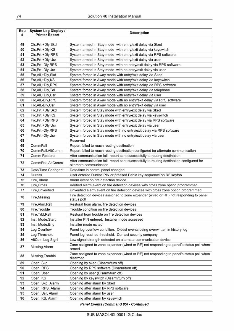
74 Solution 40 Installation Manual
SUB-MASOL40I-0001.IG.C.doc
Equ #
System Log Display / Printer Report Description
49 Cls,Prt,+Dly,Skd System armed in Stay mode with entry/exit delay via Sked 50 Cls,Prt,+Dly,KS System armed in Stay mode with entry/exit delay via keyswitch 51 Cls,Prt,+Dly,RPS System armed in Stay mode with entry/exit delay via RPS software 52 Cls,Prt,+Dly,Usr System armed in Stay mode with entry/exit delay via user 53 Cls,Prt,-Dly,RPS System armed in Stay mode with no entry/exit delay via RPS software 54 Cls,Prt,-Dly,Usr System armed in Stay mode with no entry/exit delay via user 55 Frc,All,+Dly,Skd System forced in Away mode with entry/exit delay via Sked 56 Frc,All,+Dly,KS System forced in Away mode with entry/exit delay via keyswitch 57 Frc,All,+Dly,RPS System forced in Away mode with entry/exit delay via RPS software 58 Frc,All,+Dly,Tel System forced in Away mode with entry/exit delay via telephone 59 Frc,All,+Dly,Usr System forced in Away mode with entry/exit delay via user 60 Frc,All,-Dly,RPS System forced in Away mode with no entry/exit delay via RPS software 61 Frc,All,-Dly,Usr System forced in Away mode with no entry/exit delay via user 62 Frc,Prt,+Dly,Skd System forced in Stay mode with entry/exit delay via Sked 63 Frc,Prt,+Dly,KS System forced in Stay mode with entry/exit delay via keyswitch 64 Frc,Prt,+Dly,RPS System forced in Stay mode with entry/exit delay via RPS software 65 Frc,Prt,+Dly,Usr System forced in Stay mode with entry/exit delay via user 66 Frc,Prt,-Dly,RPS System forced in Stay mode with no entry/exit delay via RPS software 67 Frc,Prt,-Dly,Usr System forced in Stay mode with no entry/exit delay via user 68 Reserved 69 CommFail Report failed to reach routing destination 70 CommFail,AltComm Report failed to reach routing destination configured for alternate communication 71 Comm Restoral After communication fail, report sent successfully to routing destination
72 CommRstl,AltComm After communication fail, report sent successfully to routing destination configured for alternate communication
73 Date/Time Changed Date/time in control panel changed 74 Duress User entered Duress PIN or pressed Panic key sequence on RF keyfob 75 Fire, Alarm Alarm event on fire detection device 76 Fire,Cross Verified alarm event on fire detection devices with cross zone option programmed 77 Fire,Unverified Unverified alarm event on fire detection devices with cross zone option programmed
78 Fire,Missing Fire detection devices assigned to zone expander (wired or RF) not responding to panel status poll
79 Fire,Alrm,Rstl Restoral from alarm, fire detection devices 80 Fire,Trouble Trouble condition on fire detection devices 81 Fire,Trbl,Rstl Restoral from trouble on fire detection devices 82 Instl Mode,Start Installer PIN entered. Installer mode accessed 83 Instl Mode,End Installer mode exited 84 Log Overflow Panel log overflow condition. Oldest events being overwritten in history log 85 Log Threshold Panel log reached threshold. Contact security company 86 AltCom Log Signl Low signal strength detected on alternate communication device
87 Missing,Alarm Zone assigned to zone expander (wired or RF) not responding to panel's status poll when armed
88 Missing,Trouble Zone assigned to zone expander (wired or RF) not responding to panel's status poll when disarmed
89 Open, Skd Opening by sked (Disarm/turn off) 90 Open, RPS Opening by RPS software (Disarm/turn off) 91 Open, User Opening by user (Disarm/turn off) 92 Open, KS Opening by keyswitch (Disarm/turn off) 93 Open, Skd, Alarm Opening after alarm by Sked 94 Open, RPS, Alarm Opening after alarm by RPS software 95 Open, Usr, Alarm Opening after alarm by user 96 Open, KS, Alarm Opening after alarm by keyswitch
Panel Events (Command 85) - Continued
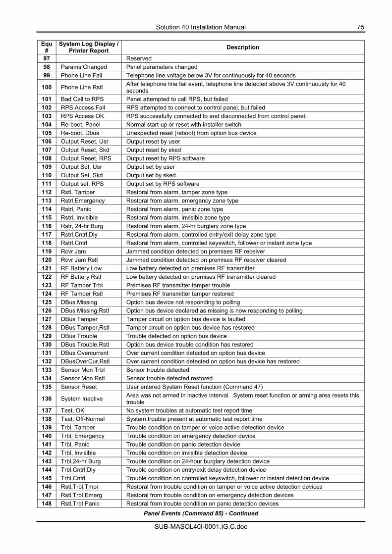
Solution 40 Installation Manual 75
SUB-MASOL40I-0001.IG.C.doc
Equ
# System Log Display /
Printer Report Description
97 Reserved 98 Params Changed Panel parameters changed 99 Phone Line Fail Telephone line voltage below 3V for continuously for 40 seconds
100 Phone Line Rstl After telephone line fail event, telephone line detected above 3V continuously for 40 seconds
101 Bad Call to RPS Panel attempted to call RPS, but failed 102 RPS Access Fail RPS attempted to connect to control panel, but failed 103 RPS Access OK RPS successfully connected to and disconnected from control panel. 104 Re-boot, Panel Normal start-up or reset with installer switch 105 Re-boot, Dbus Unexpected reset (reboot) from option bus device 106 Output Reset, Usr Output reset by user 107 Output Reset, Skd Output reset by sked 108 Output Reset, RPS Output reset by RPS software 109 Output Set, Usr Output set by user 110 Output Set, Skd Output set by sked 111 Output set, RPS Output set by RPS software 112 Rstl, Tamper Restoral from alarm, tamper zone type 113 Rstrl,Emergency Restoral from alarm, emergency zone type 114 Rstrl, Panic Restoral from alarm, panic zone type 115 Rstrl, Invisible Restoral from alarm, invisible zone type 116 Rstr, 24-hr Burg Restoral from alarm, 24-hr burglary zone type 117 Rstrl,Cntrl,Dly Restoral from alarm, controlled entry/exit delay zone type 118 Rstrl,Cntrl Restoral from alarm, controlled keyswitch, follower or instant zone type 119 Rcvr Jam Jammed condition detected on premises RF receiver 120 Rcvr Jam Rstl Jammed condition detected on premises RF receiver cleared 121 RF Battery Low Low battery detected on premises RF transmitter 122 RF Battery Rstl Low battery detected on premises RF transmitter cleared 123 RF Tamper Trbl Premises RF transmitter tamper trouble 124 RF Tamper Rstl Premises RF transmitter tamper restored 125 DBus Missing Option bus device not responding to polling 126 DBus Missing,Rstl Option bus device declared as missing is now responding to polling 127 DBus Tamper Tamper circuit on option bus device is faulted 128 DBus Tamper,Rstl Tamper circuit on option bus device has restored 129 DBus Trouble Trouble detected on option bus device 130 DBus Trouble,Rstl Option bus device trouble condition has restored 131 DBus Overcurrent Over current condition detected on option bus device 132 DBusOverCur,Rstl Over current condition detected on option bus device has restored 133 Sensor Mon Trbl Sensor trouble detected 134 Sensor Mon Rstl Sensor trouble detected restored 135 Sensor Reset User entered System Reset function (Command 47)
136 System Inactive Area was not armed in inactive interval. System reset function or arming area resets this trouble
137 Test, OK No system troubles at automatic test report time 138 Test, Off-Normal System trouble present at automatic test report time 139 Trbl, Tamper Trouble condition on tamper or voice active detection device 140 Trbl, Emergency Trouble condition on emergency detection device 141 Trbl, Panic Trouble condition on panic detection device 142 Trbl, Invisible Trouble condition on invisible detection device 143 Trbl,24-hr Burg Trouble condition on 24-hour burglary detection device 144 Trbl,Cntrl,Dly Trouble condition on entry/exit delay detection device 145 Trbl,Cntrl Trouble condition on controlled keyswitch, follower or instant detection device 146 Rstl,Trbl,Tmpr Restoral from trouble condition on tamper or voice active detection devices 147 Rstl,Trbl,Emerg Restoral from trouble condition on emergency detection devices 148 Rstl,Trbl Panic Restoral from trouble condition on panic detection devices
Panel Events (Command 85) - Continued
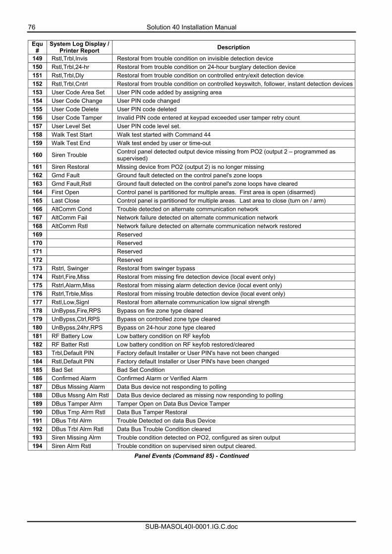
76 Solution 40 Installation Manual
SUB-MASOL40I-0001.IG.C.doc
Equ
# System Log Display /
Printer Report Description
149 Rstl,Trbl,Invis Restoral from trouble condition on invisible detection device 150 Rstl,Trbl,24-hr Restoral from trouble condition on 24-hour burglary detection device 151 Rstl,Trbl,Dly Restoral from trouble condition on controlled entry/exit detection device 152 Rstl,Trbl,Cntrl Restoral from trouble condition on controlled keyswitch, follower, instant detection devices153 User Code Area Set User PIN code added by assigning area 154 User Code Change User PIN code changed 155 User Code Delete User PIN code deleted 156 User Code Tamper Invalid PIN code entered at keypad exceeded user tamper retry count 157 User Level Set User PIN code level set. 158 Walk Test Start Walk test started with Command 44 159 Walk Test End Walk test ended by user or time-out
160 Siren Trouble Control panel detected output device missing from PO2 (output 2 – programmed as supervised)
161 Siren Restoral Missing device from PO2 (output 2) is no longer missing 162 Grnd Fault Ground fault detected on the control panel's zone loops 163 Grnd Fault,Rstl Ground fault detected on the control panel's zone loops have cleared 164 First Open Control panel is partitioned for multiple areas. First area is open (disarmed) 165 Last Close Control panel is partitioned for multiple areas. Last area to close (turn on / arm) 166 AltComm Cond Trouble detected on alternate communication network 167 AltComm Fail Network failure detected on alternate communication network 168 AltComm Rstl Network failure detected on alternate communication network restored 169 Reserved 170 Reserved 171 Reserved 172 Reserved 173 Rstrl, Swinger Restoral from swinger bypass 174 Rstrl,Fire,Miss Restoral from missing fire detection device (local event only) 175 Rstrl,Alarm,Miss Restoral from missing alarm detection device (local event only) 176 Rstrl,Trble,Miss Restoral from missing trouble detection device (local event only) 177 Rstl,Low,Signl Restoral from alternate communication low signal strength 178 UnBypss,Fire,RPS Bypass on fire zone type cleared 179 UnBypss,Ctrl,RPS Bypass on controlled zone type cleared 180 UnBypss,24hr,RPS Bypass on 24-hour zone type cleared 181 RF Battery Low Low battery condition on RF keyfob 182 RF Batter Rstl Low battery condition on RF keyfob restored/cleared 183 Trbl,Default PIN Factory default Installer or User PIN's have not been changed 184 Rstl,Default PIN Factory default Installer or User PIN's have been changed 185 Bad Set Bad Set Condition 186 Confirmed Alarm Confirmed Alarm or Verified Alarm 187 DBus Missing Alarm Data Bus device not responding to polling 188 DBus Mssng Alm Rstl Data Bus device declared as missing now responding to polling 189 DBus Tamper Alrm Tamper Open on Data Bus Device Tamper 190 DBus Tmp Alrm Rstl Data Bus Tamper Restoral 191 DBus Trbl Alrm Trouble Detected on data Bus Device 192 DBus Trbl Alrm Rstl Data Bus Trouble Condition cleared 193 Siren Missing Alrm Trouble condition detected on PO2, configured as siren output 194 Siren Alrm Rstl Trouble condition on supervised siren output cleared.
Panel Events (Command 85) - Continued
Solution 40 Installation Manual 77
SUB-MASOL40I-0001.IG.C.doc
Security System Limitations Not even the most advanced security system can guarantee protection against burglary, fire, or environmental threats. All security systems are subject to possible compromise or failure-to-warn for a variety of reasons including, but not limited to, the following:
• If sirens or horns are placed outside the hearing range of people in remote areas of the building or in
areas, which are frequently closed off, they do not provide the intended protection. • If intruders gain access through unprotected zones of entry, the system will not detect their entrance.
• If intruders have the technical means of bypassing, jamming, or disconnecting all or part of the
system, they will not be detected. • If the AC power supply is OFF and the back up battery is either missing or dead, sensors will not
detect intrusion. • Smoke detectors cannot detect smoke in chimneys, walls, or roofs, or smoke blocked by a closed door.
They may not detect smoke or fire on a level of the building different from the one on which they are located. Smoke detectors may not be able to warn in time about fires started by explosions, improper storage of flammables, overloaded electrical circuits, or other types of hazardous conditions.
• If phone lines are out of service, reports from the security system to the security company cannot be
sent. Telephone lines are vulnerable to compromise by several means. Inadequate maintenance and failure to test are the most common causes of alarm failure. It is strongly recommended that you test your system once a week to be sure that all system components are working properly. Although having a security system may make you eligible for reduced insurance premiums, the system is no substitute for insurance. Warning devices cannot compensate you for loss of life or property.
Fire Safety and Evacuation Residential fire is a leading cause of accidental death. Most fire related deaths occur at night when occupants suffocate in their sleep from smoke and toxic gases, rather than from burns. To help reduce this risk, the following program should be implemented.
1. Minimize fire hazards. Smoking in bed, cleaning with flammable liquids such as gasoline, leaving
children home alone, and using unsafe holiday decorations are some of the common causes of household fire.
2. Install a fire alarm system. The primary purpose of this system is to protect lives by giving the earliest
possible warning of danger.
3. A smoke detector should be provided to protect each sleeping area in a home.
4. Practice an escape plan. Because there may be very little time between detection of a fire and the time it becomes deadly, it is important that every member of the family understand how to quickly evacuate according to the plan.
5. Plan both primary and alternate escape routes. Since stairwells and hallways may be blocked during a
fire, exiting through a bedroom window must be a part of the escape plan. If the sleeping area is above the ground floor, install a means of safely descending outside the building if one does not already exist.
6. As a part of this plan, all family members should arrange to meet at a location away from the house
(such as a neighbours house) so you will know that everyone is accounted for. 7. If it is determined that the alarm was accidentally sounded, the siren should be silenced, the detectors
reset, and your security company notified immediately that there is no emergency situation.
78 Solution 40 Installation Manual
SUB-MASOL40I-0001.IG.C.doc
Maintenance and Service This security system requires very little maintenance, however, you should test the system weekly to ensure it is working properly. A test schedule and maintenance program can be arranged. If you notice a change in operation during normal use or testing, call for service as soon as possible. Do not attempt to repair the control panel, keypads, or detectors yourself.
Call________________________________before testing. The security system is connected to this telephone number: ______________________________________. The security control panel is connected to the phone jack located:________________________________________. RF Reciever location:____________________________.
Power Failure If the keypad indicates a power failure, and you have power in the rest of your premises, there may be a problem with the electrical transformer or circuit breaker supplying power to your security control panel. First, check to be sure that the transformer is securely plugged into the electrical outlet. If it appears to be damaged in any way, do not attempt to repair it. Call your security company for service.
AC Power Supply location:____________________________ If the transformer is plugged in, check the circuit breaker supplying power to the outlet. If the breaker is tripped, check the appliances on the circuit for signs of electrical problems. Make sure someone has not intentionally turned the breaker off. When all is clear, reset the breaker.
Circuit breaker number:____________________________
How To Clean The Keypad If your keypad gets dirty, apply a household glass cleaner to a clean cloth or paper towel and wipe the surface. Do not spray any liquid directly onto the keypad. It could run inside the case and damage electrical circuits.
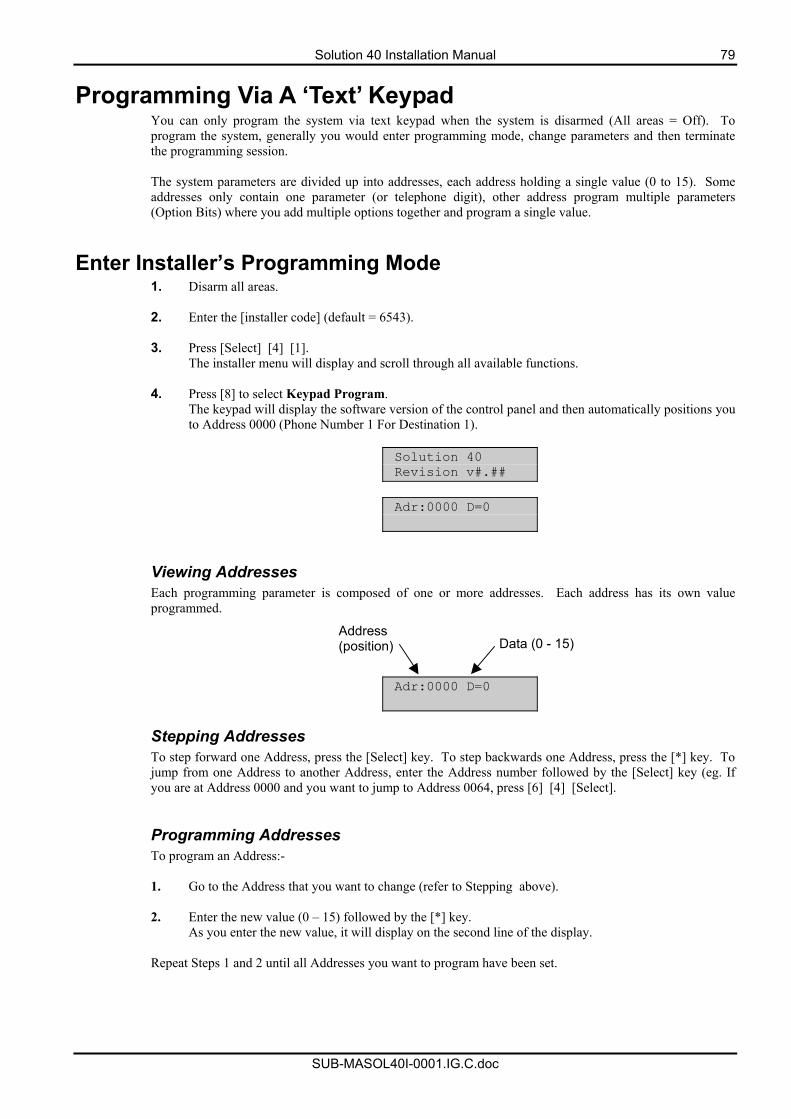
Solution 40 Installation Manual 79
SUB-MASOL40I-0001.IG.C.doc
Programming Via A ‘Text’ Keypad You can only program the system via text keypad when the system is disarmed (All areas = Off). To program the system, generally you would enter programming mode, change parameters and then terminate the programming session. The system parameters are divided up into addresses, each address holding a single value (0 to 15). Some addresses only contain one parameter (or telephone digit), other address program multiple parameters (Option Bits) where you add multiple options together and program a single value.
Enter Installer’s Programming Mode 1. Disarm all areas.
2. Enter the [installer code] (default = 6543).
3. Press [Select] [4] [1].
The installer menu will display and scroll through all available functions.
4. Press [8] to select Keypad Program. The keypad will display the software version of the control panel and then automatically positions you to Address 0000 (Phone Number 1 For Destination 1).
Solution 40 Revision v#.##
Adr:0000 D=0
Viewing Addresses Each programming parameter is composed of one or more addresses. Each address has its own value programmed.
Adr:0000 D=0
Stepping Addresses To step forward one Address, press the [Select] key. To step backwards one Address, press the [*] key. To jump from one Address to another Address, enter the Address number followed by the [Select] key (eg. If you are at Address 0000 and you want to jump to Address 0064, press [6] [4] [Select]. Programming Addresses To program an Address:- 1. Go to the Address that you want to change (refer to Stepping above).
2. Enter the new value (0 – 15) followed by the [*] key.
As you enter the new value, it will display on the second line of the display.
Repeat Steps 1 and 2 until all Addresses you want to program have been set.
Address (position) Data (0 - 15)
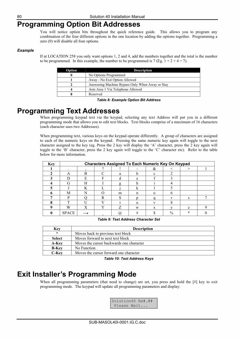
80 Solution 40 Installation Manual
SUB-MASOL40I-0001.IG.C.doc
Programming Option Bit Addresses You will notice option bits throughout the quick reference guide. This allows you to program any combination of the four different options in the one location by adding the options together. Programming a zero (0) will disable all four options.
Example If at LOCATION 258 you only want options 1, 2 and 4, add the numbers together and the total is the number to be programmed. In this example, the number to be programmed is 7 (Eg. 1 + 2 + 4 = 7).
Option Description
0 No Options Programmed 1 Away - No Exit Option Allowed 2 Answering Machine Bypass Only When Away or Stay 4 Arm Area 1 Via Telephone Allowed 8 Reserved
Table 8: Example Option Bit Address
Programming Text Addresses When programming keypad text via the keypad, selecting any text Address will put you in a different programming mode that allows you to edit text blocks. Text blocks comprise of a maximum of 16 characters (each character uses two Addresses). When programming text, various keys on the keypad operate differently. A group of characters are assigned to each of the numeric keys on the keypad. Pressing the same numeric key again will toggle to the next character assigned to the key (eg. Press the 2 key will display the ‘A’ character, press the 2 key again will toggle to the ‘B’ character, press the 2 key again will toggle to the ‘C’ character etc). Refer to the table below for more information.
Key Characters Assigned To Each Numeric Key On Keypad 1 . , ? ! - & < > 1 2 A B C a b c 2 3 D E F d e f 3 4 G H I g h i 4 5 J K L j k l 5 6 M N O m n o 6 7 P Q R S p q r s 7 8 T U V t u v 8 9 W X Y Z w x y z 9 0 SPACE → _ @ # $ % * 0
Table 9: Text Address Character Set
Key Description * Moves back to previous text block
Select Moves forward to next text block A-Key Moves the cursor backwards one character B-Key No Function C-Key Moves the cursor forward one character
Table 10: Text Address Keys
Exit Installer’s Programming Mode When all programming parameters (that need to change) are set, you press and hold the [#] key to exit programming mode. The keypad will update all programming parameters and display:
Solution40 Re#.## Please Wait...
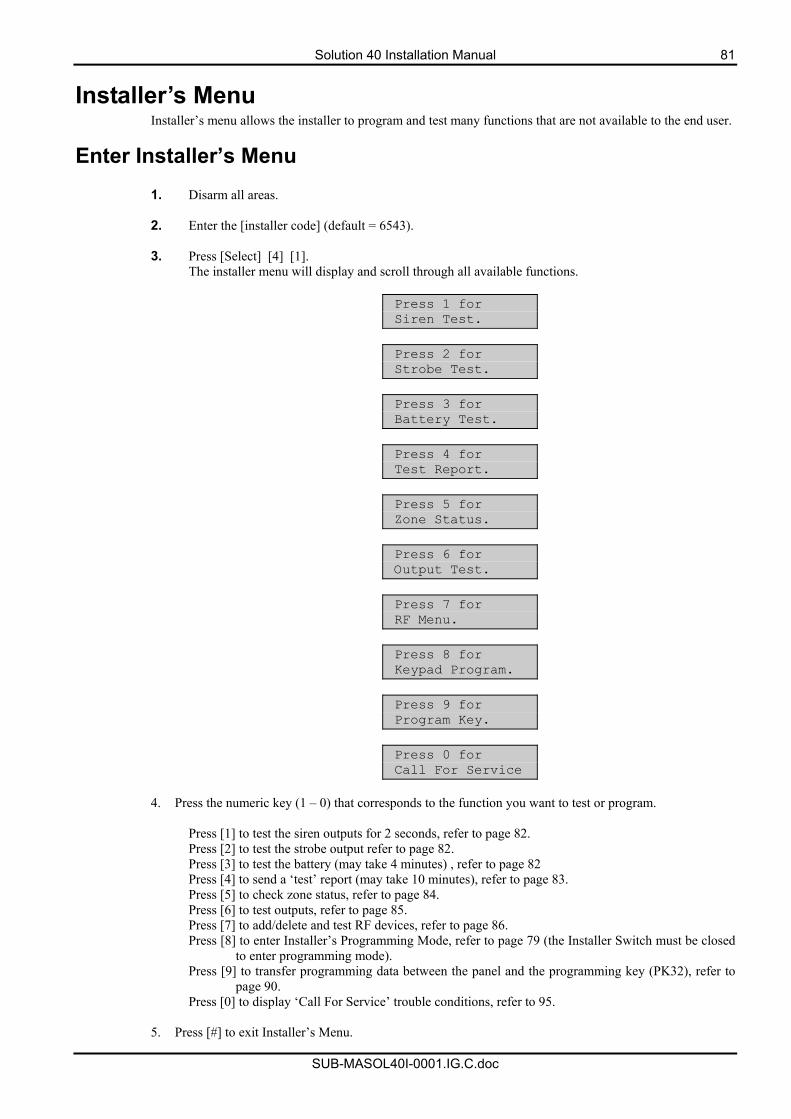
Solution 40 Installation Manual 81
SUB-MASOL40I-0001.IG.C.doc
Installer’s Menu Installer’s menu allows the installer to program and test many functions that are not available to the end user.
Enter Installer’s Menu
1. Disarm all areas.
2. Enter the [installer code] (default = 6543).
3. Press [Select] [4] [1]. The installer menu will display and scroll through all available functions.
Press 1 for Siren Test.
Press 2 for Strobe Test.
Press 3 for Battery Test.
Press 4 for Test Report.
Press 5 for Zone Status.
Press 6 for Output Test.
Press 7 for RF Menu.
Press 8 for Keypad Program.
Press 9 for Program Key.
Press 0 for Call For Service
4. Press the numeric key (1 – 0) that corresponds to the function you want to test or program.
Press [1] to test the siren outputs for 2 seconds, refer to page 82. Press [2] to test the strobe output refer to page 82. Press [3] to test the battery (may take 4 minutes) , refer to page 82 Press [4] to send a ‘test’ report (may take 10 minutes), refer to page 83. Press [5] to check zone status, refer to page 84. Press [6] to test outputs, refer to page 85. Press [7] to add/delete and test RF devices, refer to page 86. Press [8] to enter Installer’s Programming Mode, refer to page 79 (the Installer Switch must be closed
to enter programming mode). Press [9] to transfer programming data between the panel and the programming key (PK32), refer to
page 90. Press [0] to display ‘Call For Service’ trouble conditions, refer to 95.
5. Press [#] to exit Installer’s Menu.
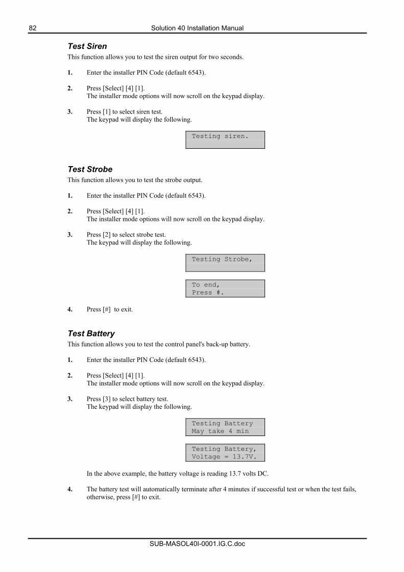
82 Solution 40 Installation Manual
SUB-MASOL40I-0001.IG.C.doc
Test Siren This function allows you to test the siren output for two seconds. 1. Enter the installer PIN Code (default 6543).
2. Press [Select] [4] [1].
The installer mode options will now scroll on the keypad display.
3. Press [1] to select siren test. The keypad will display the following.
Testing siren.
Test Strobe This function allows you to test the strobe output. 1. Enter the installer PIN Code (default 6543).
2. Press [Select] [4] [1].
The installer mode options will now scroll on the keypad display.
3. Press [2] to select strobe test. The keypad will display the following.
Testing Strobe,
To end, Press #.
4. Press [#] to exit.
Test Battery This function allows you to test the control panel's back-up battery. 1. Enter the installer PIN Code (default 6543).
2. Press [Select] [4] [1].
The installer mode options will now scroll on the keypad display.
3. Press [3] to select battery test. The keypad will display the following.
Testing Battery May take 4 min
Testing Battery, Voltage = 13.7V.
In the above example, the battery voltage is reading 13.7 volts DC.
4. The battery test will automatically terminate after 4 minutes if successful test or when the test fails,
otherwise, press [#] to exit.
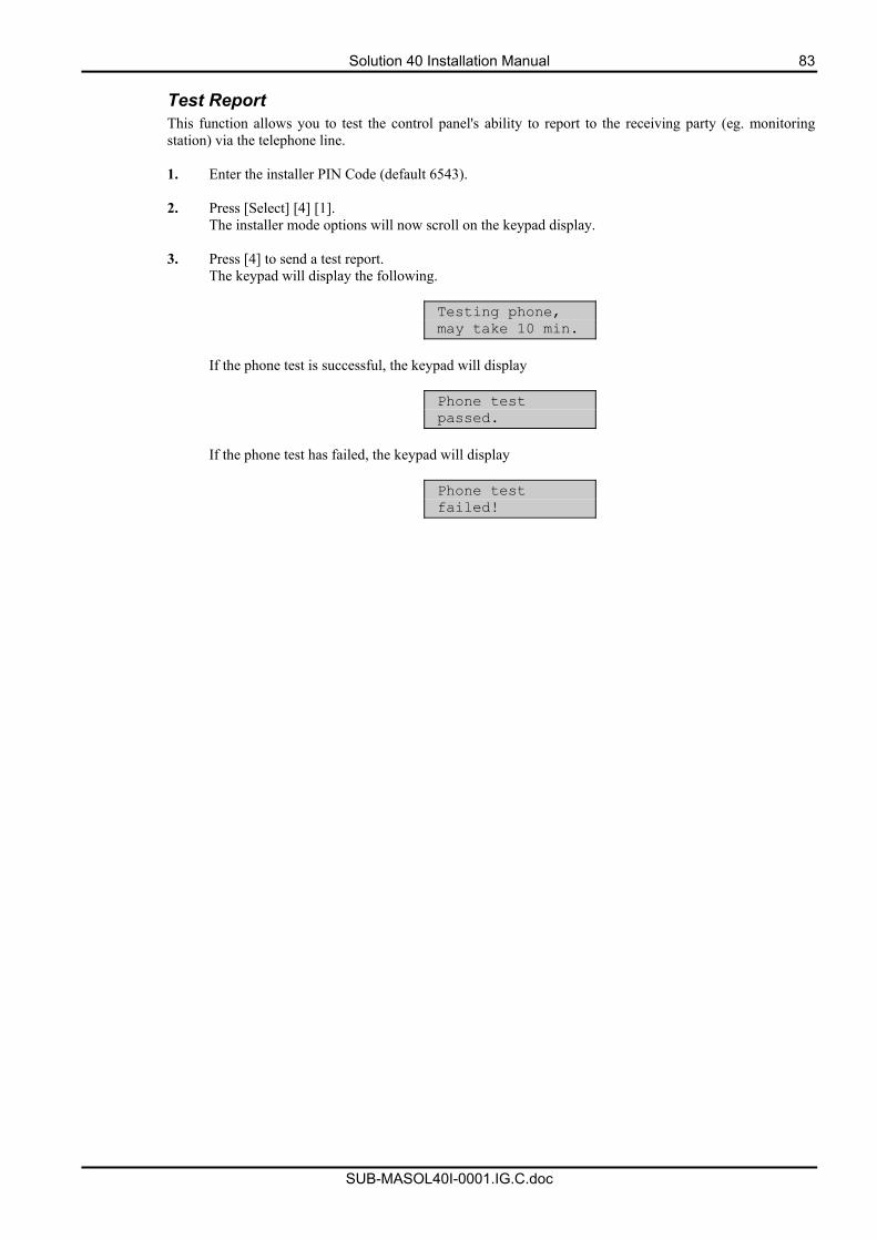
Solution 40 Installation Manual 83
SUB-MASOL40I-0001.IG.C.doc
Test Report This function allows you to test the control panel's ability to report to the receiving party (eg. monitoring station) via the telephone line. 1. Enter the installer PIN Code (default 6543).
2. Press [Select] [4] [1].
The installer mode options will now scroll on the keypad display.
3. Press [4] to send a test report. The keypad will display the following.
Testing phone, may take 10 min.
If the phone test is successful, the keypad will display
Phone test passed.
If the phone test has failed, the keypad will display
Phone test failed!
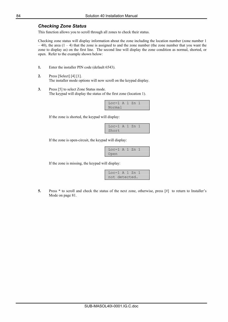
84 Solution 40 Installation Manual
SUB-MASOL40I-0001.IG.C.doc
Checking Zone Status This function allows you to scroll through all zones to check their status. Checking zone status will display information about the zone including the location number (zone number 1 – 40), the area (1 – 4) that the zone is assigned to and the zone number (the zone number that you want the zone to display as) on the first line. The second line will display the zone condition as normal, shorted, or open. Refer to the example shown below: 1. Enter the installer PIN code (default 6543).
2. Press [Select] [4] [1].
The installer mode options will now scroll on the keypad display.
3. Press [5] to select Zone Status mode. The keypad will display the status of the first zone (location 1).
Loc-1 A 1 Zn 1 Normal
If the zone is shorted, the keypad will display:
Loc-1 A 1 Zn 1 Short
If the zone is open-circuit, the keypad will display:
Loc-1 A 1 Zn 1 Open
If the zone is missing, the keypad will display:
Loc-1 A 1 Zn 1 not detected.
5. Press * to scroll and check the status of the next zone, otherwise, press [#] to return to Installer’s Mode on page 81.
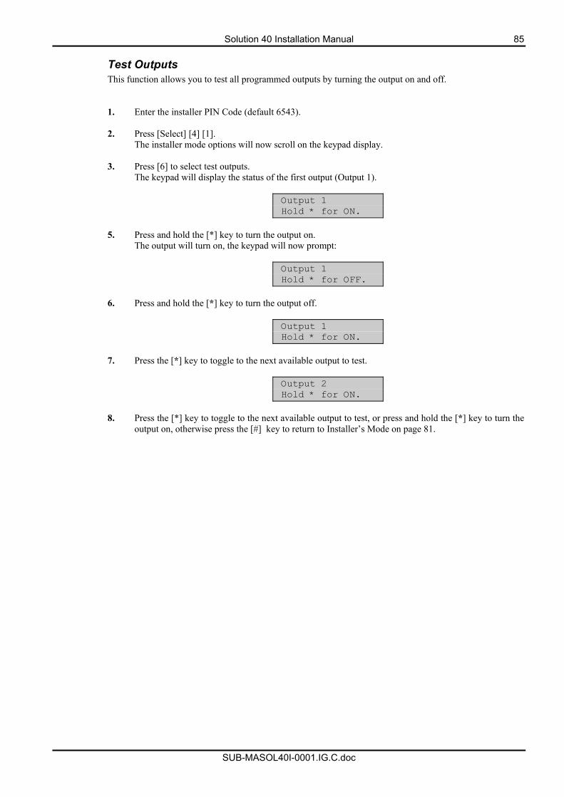
Solution 40 Installation Manual 85
SUB-MASOL40I-0001.IG.C.doc
Test Outputs This function allows you to test all programmed outputs by turning the output on and off.
1. Enter the installer PIN Code (default 6543).
2. Press [Select] [4] [1].
The installer mode options will now scroll on the keypad display.
3. Press [6] to select test outputs. The keypad will display the status of the first output (Output 1).
Output 1 Hold * for ON.
5. Press and hold the [*] key to turn the output on.
The output will turn on, the keypad will now prompt:
Output 1 Hold * for OFF.
6. Press and hold the [*] key to turn the output off.
Output 1 Hold * for ON.
7. Press the [*] key to toggle to the next available output to test.
Output 2 Hold * for ON.
8. Press the [*] key to toggle to the next available output to test, or press and hold the [*] key to turn the
output on, otherwise press the [#] key to return to Installer’s Mode on page 81.
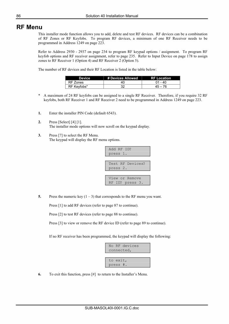
86 Solution 40 Installation Manual
SUB-MASOL40I-0001.IG.C.doc
RF Menu This installer mode function allows you to add, delete and test RF devices. RF devices can be a combination of RF Zones or RF Keyfobs. To program RF devices, a minimum of one RF Receiver needs to be programmed in Address 1249 on page 223. Refer to Address 2930 - 2937 on page 234 to program RF keypad options / assignment. To program RF keyfob options and RF receiver assignment, refer to page 235. Refer to Input Device on page 178 to assign zones to RF Receiver 1 (Option 4) and RF Receiver 2 (Option 5). The number of RF devices and their RF Location is listed in the table below:
Device # Devices Allowed RF Location
RF Zones 40 01 - 40 RF Keyfobs* 32 45 – 76
* A maximum of 24 RF keyfobs can be assigned to a single RF Receiver. Therefore, if you require 32 RF
keyfobs, both RF Receiver 1 and RF Receiver 2 need to be programmed in Address 1249 on page 223.
1. Enter the installer PIN Code (default 6543).
2. Press [Select] [4] [1]. The installer mode options will now scroll on the keypad display.
3. Press [7] to select the RF Menu.
The keypad will display the RF menu options.
Add RF ID? press 1.
Test RF Devices? press 2.
View or Remove RF ID? press 3.
5. Press the numeric key (1 – 3) that corresponds to the RF menu you want.
Press [1] to add RF devices (refer to page 87 to continue). Press [2] to test RF devices (refer to page 88 to continue). Press [3] to view or remove the RF device ID (refer to page 89 to continue).
If no RF receiver has been programmed, the keypad will display the following:
No RF devices connected,
to exit, press #.
6. To exit this function, press [#] to return to the Installer’s Menu.
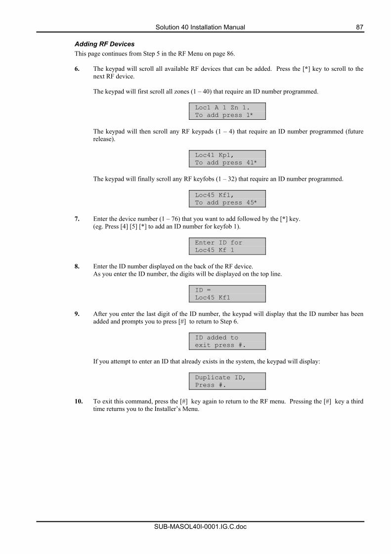
Solution 40 Installation Manual 87
SUB-MASOL40I-0001.IG.C.doc
Adding RF Devices This page continues from Step 5 in the RF Menu on page 86.
6. The keypad will scroll all available RF devices that can be added. Press the [*] key to scroll to the
next RF device. The keypad will first scroll all zones (1 – 40) that require an ID number programmed.
Loc1 A 1 Zn 1. To add press 1*
The keypad will then scroll any RF keypads (1 – 4) that require an ID number programmed (future release).
Loc41 Kp1, To add press 41*
The keypad will finally scroll any RF keyfobs (1 – 32) that require an ID number programmed.
Loc45 Kf1, To add press 45*
7. Enter the device number (1 – 76) that you want to add followed by the [*] key.
(eg. Press [4] [5] [*] to add an ID number for keyfob 1).
Enter ID for Loc45 Kf 1
8. Enter the ID number displayed on the back of the RF device.
As you enter the ID number, the digits will be displayed on the top line.
ID = Loc45 Kf1
9. After you enter the last digit of the ID number, the keypad will display that the ID number has been
added and prompts you to press [#] to return to Step 6.
ID added to exit press #.
If you attempt to enter an ID that already exists in the system, the keypad will display:
Duplicate ID, Press #.
10. To exit this command, press the [#] key again to return to the RF menu. Pressing the [#] key a third
time returns you to the Installer’s Menu.
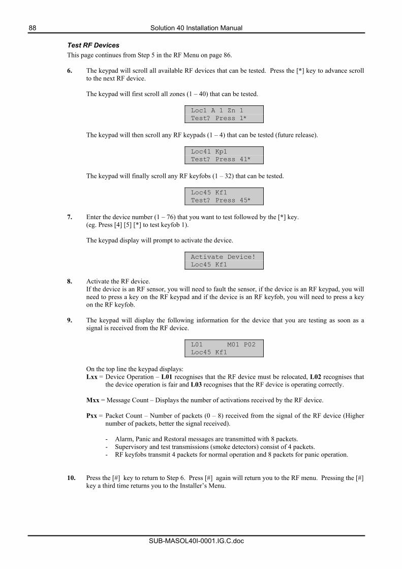
88 Solution 40 Installation Manual
SUB-MASOL40I-0001.IG.C.doc
Test RF Devices This page continues from Step 5 in the RF Menu on page 86.
6. The keypad will scroll all available RF devices that can be tested. Press the [*] key to advance scroll
to the next RF device. The keypad will first scroll all zones (1 – 40) that can be tested.
Loc1 A 1 Zn 1 Test? Press 1*
The keypad will then scroll any RF keypads (1 – 4) that can be tested (future release).
Loc41 Kp1 Test? Press 41*
The keypad will finally scroll any RF keyfobs (1 – 32) that can be tested.
Loc45 Kf1 Test? Press 45*
7. Enter the device number (1 – 76) that you want to test followed by the [*] key.
(eg. Press [4] [5] [*] to test keyfob 1). The keypad display will prompt to activate the device.
Activate Device! Loc45 Kf1
8. Activate the RF device.
If the device is an RF sensor, you will need to fault the sensor, if the device is an RF keypad, you will need to press a key on the RF keypad and if the device is an RF keyfob, you will need to press a key on the RF keyfob.
9. The keypad will display the following information for the device that you are testing as soon as a signal is received from the RF device.
L01 M01 P02 Loc45 Kf1
On the top line the keypad displays: Lxx = Device Operation – L01 recognises that the RF device must be relocated, L02 recognises that
the device operation is fair and L03 recognises that the RF device is operating correctly. Mxx = Message Count – Displays the number of activations received by the RF device. Pxx = Packet Count – Number of packets (0 – 8) received from the signal of the RF device (Higher
number of packets, better the signal received).
- Alarm, Panic and Restoral messages are transmitted with 8 packets. - Supervisory and test transmissions (smoke detectors) consist of 4 packets. - RF keyfobs transmit 4 packets for normal operation and 8 packets for panic operation.
10. Press the [#] key to return to Step 6. Press [#] again will return you to the RF menu. Pressing the [#]
key a third time returns you to the Installer’s Menu.
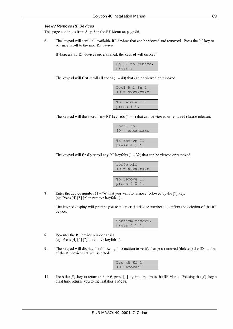
Solution 40 Installation Manual 89
SUB-MASOL40I-0001.IG.C.doc
View / Remove RF Devices This page continues from Step 5 in the RF Menu on page 86.
6. The keypad will scroll all available RF devices that can be viewed and removed. Press the [*] key to
advance scroll to the next RF device. If there are no RF devices programmed, the keypad will display:
No RF to remove, press #.
The keypad will first scroll all zones (1 – 40) that can be viewed or removed.
Loc1 A 1 Zn 1 ID = xxxxxxxxx
To remove ID press 1 *.
The keypad will then scroll any RF keypads (1 – 4) that can be viewed or removed (future release).
Loc41 Kp1 ID = xxxxxxxxx
To remove ID press 4 1 *.
The keypad will finally scroll any RF keyfobs (1 – 32) that can be viewed or removed.
Loc45 Kf1 ID = xxxxxxxxx
To remove ID press 4 5 *.
7. Enter the device number (1 – 76) that you want to remove followed by the [*] key.
(eg. Press [4] [5] [*] to remove keyfob 1). The keypad display will prompt you to re-enter the device number to confirm the deletion of the RF device.
Confirm remove, press 4 5 *.
8. Re-enter the RF device number again.
(eg. Press [4] [5] [*] to remove keyfob 1).
9. The keypad will display the following information to verify that you removed (deleted) the ID number of the RF device that you selected.
Loc 45 Kf 1, ID removed.
10. Press the [#] key to return to Step 6, press [#] again to return to the RF Menu. Pressing the [#] key a
third time returns you to the Installer’s Menu.
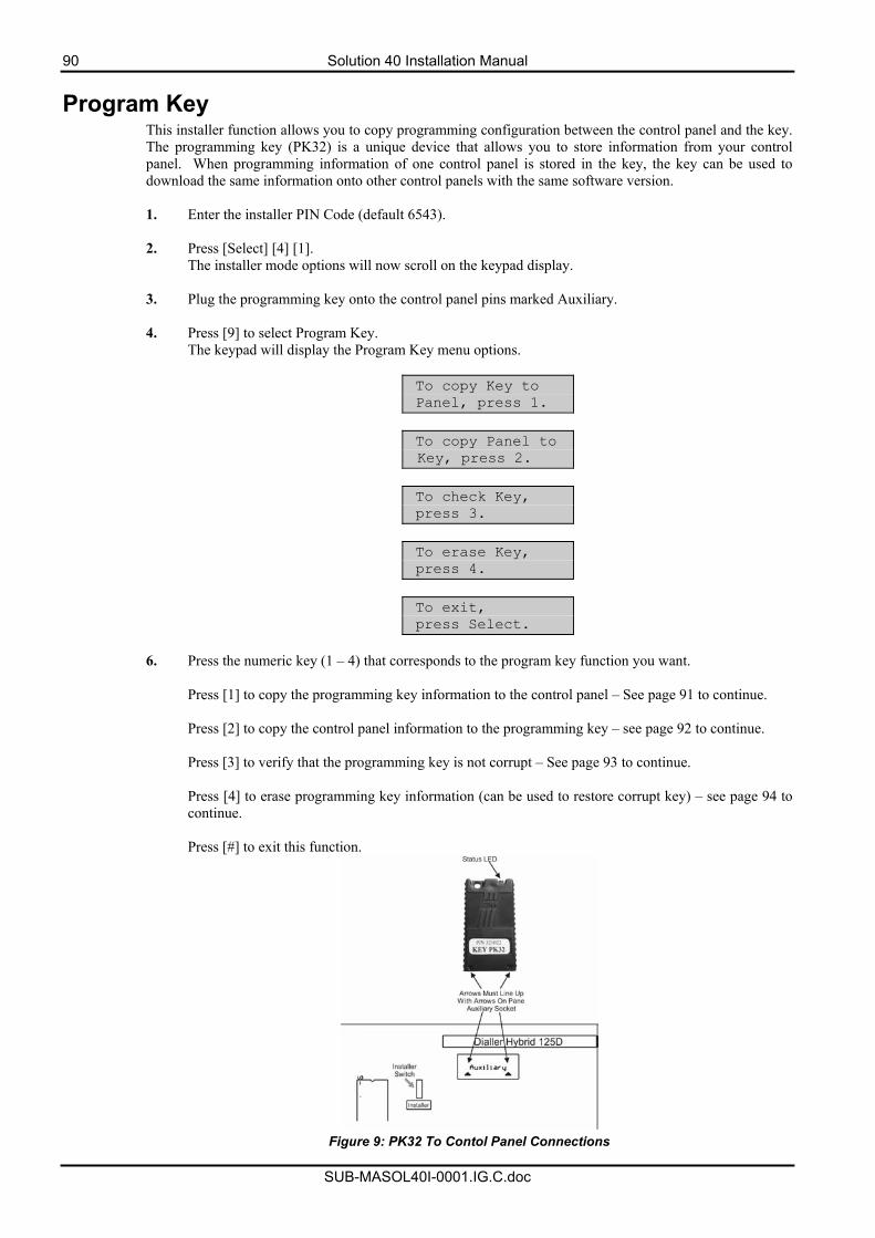
90 Solution 40 Installation Manual
SUB-MASOL40I-0001.IG.C.doc
Program Key This installer function allows you to copy programming configuration between the control panel and the key. The programming key (PK32) is a unique device that allows you to store information from your control panel. When programming information of one control panel is stored in the key, the key can be used to download the same information onto other control panels with the same software version.
1. Enter the installer PIN Code (default 6543).
2. Press [Select] [4] [1].
The installer mode options will now scroll on the keypad display.
3. Plug the programming key onto the control panel pins marked Auxiliary.
4. Press [9] to select Program Key. The keypad will display the Program Key menu options.
To copy Key to Panel, press 1.
To copy Panel to Key, press 2.
To check Key, press 3.
To erase Key, press 4.
To exit, press Select.
6. Press the numeric key (1 – 4) that corresponds to the program key function you want.
Press [1] to copy the programming key information to the control panel – See page 91 to continue. Press [2] to copy the control panel information to the programming key – see page 92 to continue. Press [3] to verify that the programming key is not corrupt – See page 93 to continue. Press [4] to erase programming key information (can be used to restore corrupt key) – see page 94 to continue. Press [#] to exit this function.
Figure 9: PK32 To Contol Panel Connections
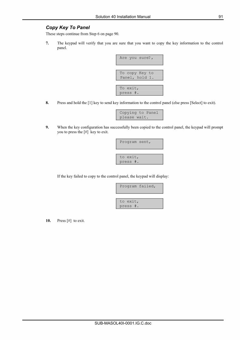
Solution 40 Installation Manual 91
SUB-MASOL40I-0001.IG.C.doc
Copy Key To Panel These steps continue from Step 6 on page 90.
7. The keypad will verify that you are sure that you want to copy the key information to the control
panel.
Are you sure?,
To copy Key to Panel, hold 1.
To exit, press #.
8. Press and hold the [1] key to send key information to the control panel (else press [Select] to exit).
Copying to Panel please wait.
9. When the key configuration has successfully been copied to the control panel, the keypad will prompt
you to press the [#] key to exit.
Program sent,
to exit, press #.
If the key failed to copy to the control panel, the keypad will display:
Program failed,
to exit, press #.
10. Press [#] to exit.
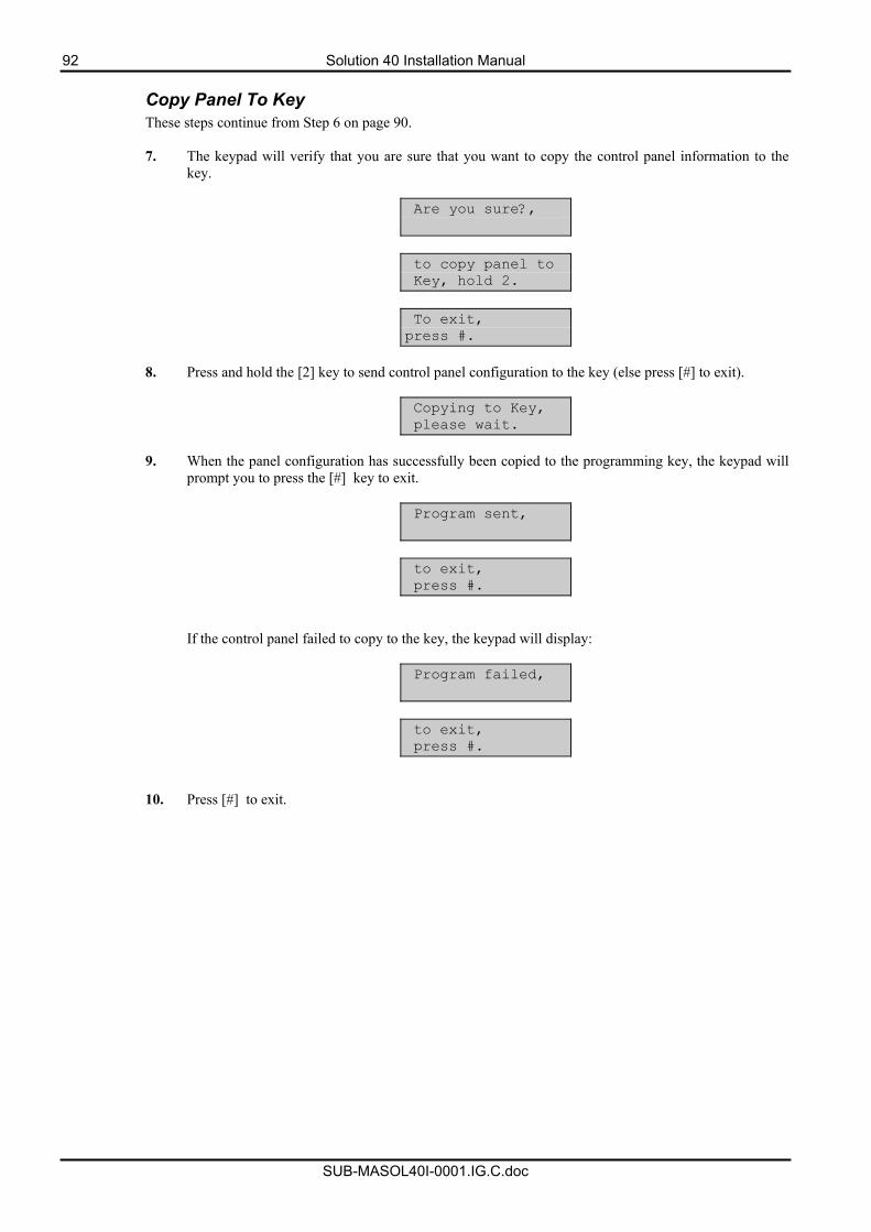
92 Solution 40 Installation Manual
SUB-MASOL40I-0001.IG.C.doc
Copy Panel To Key These steps continue from Step 6 on page 90.
7. The keypad will verify that you are sure that you want to copy the control panel information to the
key.
Are you sure?,
to copy panel to Key, hold 2.
To exit, press #.
8. Press and hold the [2] key to send control panel configuration to the key (else press [#] to exit).
Copying to Key, please wait.
9. When the panel configuration has successfully been copied to the programming key, the keypad will
prompt you to press the [#] key to exit.
Program sent,
to exit, press #.
If the control panel failed to copy to the key, the keypad will display:
Program failed,
to exit, press #.
10. Press [#] to exit.
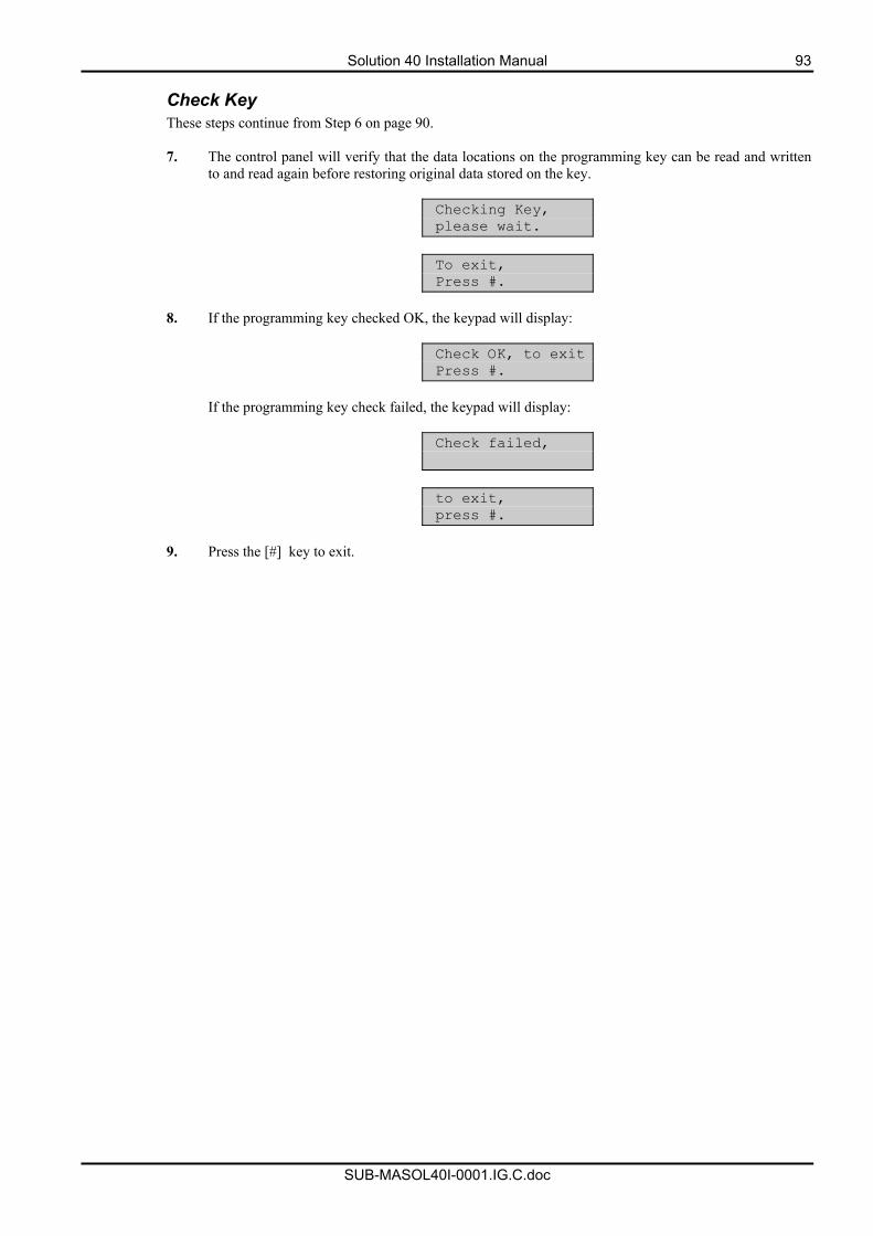
Solution 40 Installation Manual 93
SUB-MASOL40I-0001.IG.C.doc
Check Key These steps continue from Step 6 on page 90.
7. The control panel will verify that the data locations on the programming key can be read and written
to and read again before restoring original data stored on the key.
Checking Key, please wait.
To exit, Press #.
8. If the programming key checked OK, the keypad will display:
Check OK, to exit Press #.
If the programming key check failed, the keypad will display:
Check failed,
to exit, press #.
9. Press the [#] key to exit.
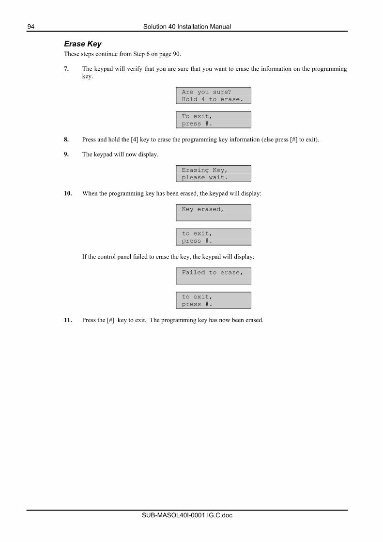
94 Solution 40 Installation Manual
SUB-MASOL40I-0001.IG.C.doc
Erase Key These steps continue from Step 6 on page 90.
7. The keypad will verify that you are sure that you want to erase the information on the programming
key.
Are you sure? Hold 4 to erase.
To exit, press #.
8. Press and hold the [4] key to erase the programming key information (else press [#] to exit). 9. The keypad will now display.
Erasing Key, please wait.
10. When the programming key has been erased, the keypad will display:
Key erased,
to exit, press #.
If the control panel failed to erase the key, the keypad will display:
Failed to erase,
to exit, press #.
11. Press the [#] key to exit. The programming key has now been erased.
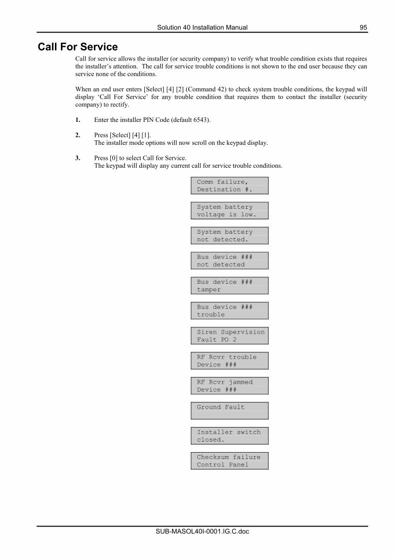
Solution 40 Installation Manual 95
SUB-MASOL40I-0001.IG.C.doc
Call For Service Call for service allows the installer (or security company) to verify what trouble condition exists that requires the installer’s attention. The call for service trouble conditions is not shown to the end user because they can service none of the conditions. When an end user enters [Select] [4] [2] (Command 42) to check system trouble conditions, the keypad will display ‘Call For Service’ for any trouble condition that requires them to contact the installer (security company) to rectify.
1. Enter the installer PIN Code (default 6543).
2. Press [Select] [4] [1].
The installer mode options will now scroll on the keypad display.
3. Press [0] to select Call for Service. The keypad will display any current call for service trouble conditions.
Comm failure, Destination #.
System battery voltage is low.
System battery not detected.
Bus device ### not detected
Bus device ### tamper
Bus device ### trouble
Siren Supervision Fault PO 2
RF Rcvr trouble Device ###
RF Rcvr jammed Device ###
Ground Fault
Installer switch closed.
Checksum failure Control Panel
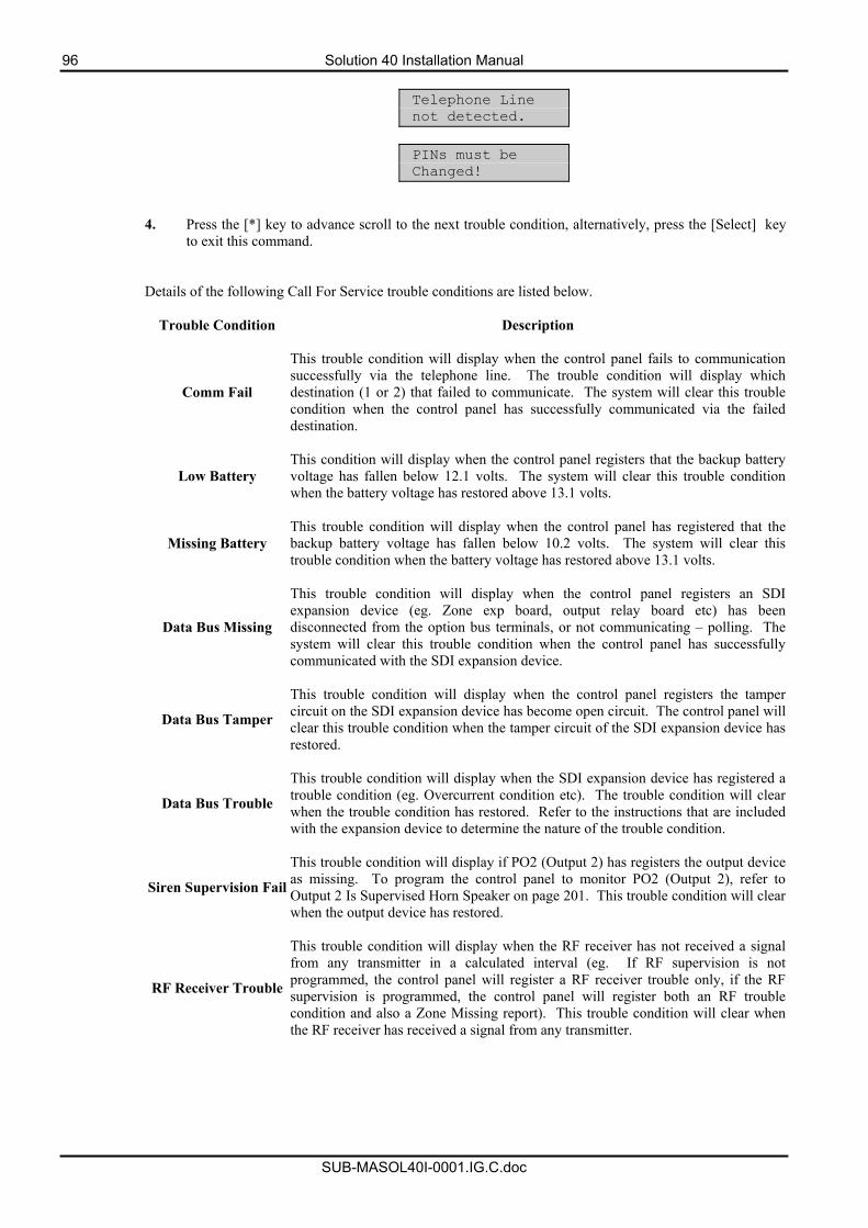
96 Solution 40 Installation Manual
SUB-MASOL40I-0001.IG.C.doc
Telephone Line not detected.
PINs must be Changed!
4. Press the [*] key to advance scroll to the next trouble condition, alternatively, press the [Select] key to exit this command.
Details of the following Call For Service trouble conditions are listed below.
Trouble Condition Description
Comm Fail
This trouble condition will display when the control panel fails to communicationsuccessfully via the telephone line. The trouble condition will display whichdestination (1 or 2) that failed to communicate. The system will clear this troublecondition when the control panel has successfully communicated via the faileddestination.
Low Battery This condition will display when the control panel registers that the backup batteryvoltage has fallen below 12.1 volts. The system will clear this trouble conditionwhen the battery voltage has restored above 13.1 volts.
Missing Battery This trouble condition will display when the control panel has registered that thebackup battery voltage has fallen below 10.2 volts. The system will clear thistrouble condition when the battery voltage has restored above 13.1 volts.
Data Bus Missing
This trouble condition will display when the control panel registers an SDIexpansion device (eg. Zone exp board, output relay board etc) has beendisconnected from the option bus terminals, or not communicating – polling. The system will clear this trouble condition when the control panel has successfullycommunicated with the SDI expansion device.
Data Bus Tamper
This trouble condition will display when the control panel registers the tamper circuit on the SDI expansion device has become open circuit. The control panel willclear this trouble condition when the tamper circuit of the SDI expansion device hasrestored.
Data Bus Trouble
This trouble condition will display when the SDI expansion device has registered atrouble condition (eg. Overcurrent condition etc). The trouble condition will clearwhen the trouble condition has restored. Refer to the instructions that are included with the expansion device to determine the nature of the trouble condition.
Siren Supervision Fail
This trouble condition will display if PO2 (Output 2) has registers the output deviceas missing. To program the control panel to monitor PO2 (Output 2), refer to Output 2 Is Supervised Horn Speaker on page 201. This trouble condition will clear when the output device has restored.
RF Receiver Trouble
This trouble condition will display when the RF receiver has not received a signalfrom any transmitter in a calculated interval (eg. If RF supervision is notprogrammed, the control panel will register a RF receiver trouble only, if the RF supervision is programmed, the control panel will register both an RF troublecondition and also a Zone Missing report). This trouble condition will clear whenthe RF receiver has received a signal from any transmitter.
Solution 40 Installation Manual 97
SUB-MASOL40I-0001.IG.C.doc
Trouble Condition Description
RF Receiver Jammed This trouble condition will display when the RF receiver senses that it is beingjammed. The trouble condition will clear when the jammed condition clears.
Ground Fault This trouble condition occurs when any (-) zone terminal has been shorted to the earth terminal. This trouble condition will clear when the short between the (-) zone terminal and the earth terminal has been removed.
Installer Switch Closed
This trouble condition occurs when the installer switch remains shorted (closed)when you are not in Installers Programming Mode. The trouble condition will clearwhen the switch is open circuit.
Checksum Fail This trouble condition occurs on start-up when you change an address value and reset the power supply of the control panel without exiting programming mode first.
Telephone Line
Missing This trouble condition occurs when the control panel registers that the telephone line has been disconnected continuously for a minimum of 40 seconds.
PINs Must Be
Changed This trouble will occur when the default PIN codes for either User 1 or the InstallerPIN have not been changed.
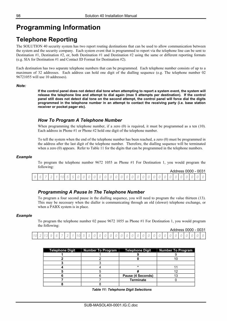
98 Solution 40 Installation Manual
SUB-MASOL40I-0001.IG.C.doc
Programming Information
Telephone Reporting The SOLUTION 40 security system has two report routing destinations that can be used to allow communication between the system and the security company. Each system event that is programmed to report via the telephone line can be sent to Destination #1, Destination #2, or, both Destination #1 and Destination #2 using the same or different reporting formats (e.g. SIA for Destination #1 and Contact ID Format for Destination #2). Each destination has two separate telephone numbers that can be programmed. Each telephone number consists of up to a maximum of 32 addresses. Each address can hold one digit of the dialling sequence (e.g. The telephone number 02 96721055 will use 10 addresses). Note:
If the control panel does not detect dial tone when attempting to report a system event, the system will release the telephone line and attempt to dial again (max 5 attempts per destination). If the control panel still does not detect dial tone on the second attempt, the control panel will force dial the digits programmed in the telephone number in an attempt to contact the receiving party (i.e. base station receiver or pocket pager etc).
How To Program A Telephone Number When programming the telephone number, if a zero (0) is required, it must be programmed as a ten (10). Each address in Phone #1 or Phone #2 hold one digit of the telephone number. To tell the system when the end of the telephone number has been reached, a zero (0) must be programmed in the address after the last digit of the telephone number. Therefore, the dialling sequence will be terminated when a zero (0) appears. Refer to Table 11 for the digits that can be programmed in the telephone numbers.
Example
To program the telephone number 9672 1055 as Phone #1 For Destination 1, you would program the following:
Address 0000 - 0031 9 6 7 2 1 10 5 5 0 0 0 0 0 0 0 0 0 0 0 0 0 0 0 0 0 0 0 0 0 0 0 0
Programming A Pause In The Telephone Number To program a four second pause in the dialling sequence, you will need to program the value thirteen (13). This may be necessary when the dialler is communicating through an old (slower) telephone exchange, or when a PABX system is in place.
Example
To program the telephone number 02 pause 9672 1055 as Phone #1 For Destination 1, you would program the following:
Address 0000 - 0031 10 2 13 9 6 7 2 1 10 5 5 0 0 0 0 0 0 0 0 0 0 0 0 0 0 0 0 0 0 0 0 0
Telephone Digit Number To Program Telephone Digit Number To Program 1 1 9 9 2 2 0 10 3 3 4 4 * 11 5 5 # 12 6 6 Pause (4 Seconds) 13 7 7 Terminate 0 8 8
Table 11: Telephone Digit Selections
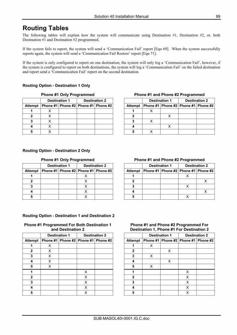
Solution 40 Installation Manual 99
SUB-MASOL40I-0001.IG.C.doc
Routing Tables The following tables will explain how the system will communicate using Destination #1, Destination #2, or, both Destination #1 and Destination #2 programmed. If the system fails to report, the system will send a ‘Communication Fail’ report [Equ 69]. When the system successfully reports again, the system will send a ‘Communication Fail Restore’ report [Equ 71]. If the system is only configured to report on one destination, the system will only log a ‘Communication Fail’, however, if the system is configured to report on both destinations, the system will log a ‘Communication Fail’ on the failed destination and report send a ‘Communication Fail’ report on the second destination. Routing Option - Destination 1 Only
Phone #1 Only Programmed Phone #1 and Phone #2 Programmed Destination 1 Destination 2 Destination 1 Destination 2
Attempt Phone #1 Phone #2 Phone #1 Phone #2 Attempt Phone #1 Phone #2 Phone #1 Phone #21 X 1 X 2 X 2 X 3 X 3 X 4 X 4 X 5 X 5 X
Routing Option - Destination 2 Only
Phone #1 Only Programmed Phone #1 and Phone #2 Programmed Destination 1 Destination 2 Destination 1 Destination 2
Attempt Phone #1 Phone #2 Phone #1 Phone #2 Attempt Phone #1 Phone #2 Phone #1 Phone #21 X 1 X 2 X 2 X 3 X 3 X 4 X 4 X 5 X 5 X
Routing Option - Destination 1 and Destination 2 Phone #1 Programmed For Both Destination 1
and Destination 2 Phone #1 and Phone #2 Programmed For
Destination 1, Phone #1 For Destination 2 Destination 1 Destination 2 Destination 1 Destination 2
Attempt Phone #1 Phone #2 Phone #1 Phone #2 Attempt Phone #1 Phone #2 Phone #1 Phone #21 X 1 X 2 X 2 X 3 X 3 X 4 X 4 X 5 X 5 X 1 X 1 X 2 X 2 X 3 X 3 X 4 X 4 X 5 X 5 X
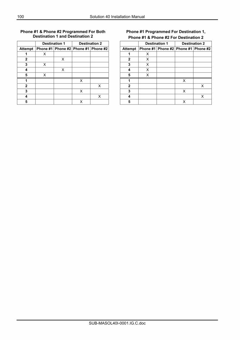
100 Solution 40 Installation Manual
SUB-MASOL40I-0001.IG.C.doc
Phone #1 & Phone #2 Programmed For Both Destination 1 and Destination 2
Phone #1 Programmed For Destination 1, Phone #1 & Phone #2 For Destination 2
Destination 1 Destination 2 Destination 1 Destination 2 Attempt Phone #1 Phone #2 Phone #1 Phone #2 Attempt Phone #1 Phone #2 Phone #1 Phone #2
1 X 1 X 2 X 2 X 3 X 3 X 4 X 4 X 5 X 5 X 1 X 1 X 2 X 2 X 3 X 3 X 4 X 4 X 5 X 5 X
Solution 40 Installation Manual 101
SUB-MASOL40I-0001.IG.C.doc
Securitel Format Securitel is an alternative monitoring protocol used for reporting via an existing telephone line that is supervised by the monitoring company. Telephone line faults or deliberately cut lines can be detected. Securitel is programmed by setting Address 0064 on page 112 (Destination 1) or Address 0130 on page 113 (Destination 2) to the value of 5. The securitel unit is connected to the control panel via the special cable and interface module (See Figure 10 and 11 for details). The Securitel unit also connects to the telephone line for reporting. The ‘Securitel Interface Unit’ is uniquely identified by its “Hard ID” (Area 1 Account Number) number to the monitoring station. This “Hard ID” is initialised on the start up of the control panel, which sends an initialisation command containing the first 4 digits of the Area 1 Account Number to the ‘Securitel Interface Unit’. The Securitel Unit uses this 4 digit hexadecimal number as the “Hard ID” which uniquely identifies it to the monitoring station. Securitel “Hard ID” is programmed by inputting ID at Address 0276-0281 on page 256 (Area 1 Account Number). Once the hardware connection and programming is complete confirm that H2 on the STU is flashing occasionally, this will confirm that the STU has seen the Securitel pilot tone. Alternatively to confirm that the securitel pilot tone is present, a telephone handset may be placed on the line and an audio chirp should be heard at intervals. If the Securitel pilot tone is not present, contact the monitoring station for further assistance.
To send a report to the monitoring station the panel may be armed or disarmed. It should be observed that H1 will be activated if the STU has been upped by the monitoring station. If there is no report responce then the monitoring station will have to be contacted to “up the STU”, which reactivates the connection to the STU. If the STU has been “Upped” correctly then activity should be observed at the monitoring station. For full specifications on the Securitel unit, refer to the MCM electronics website www.mcmelectronics.com.au.
Note The Security Interface does not support multiple “Hard ID” numbers (Account Numbers).
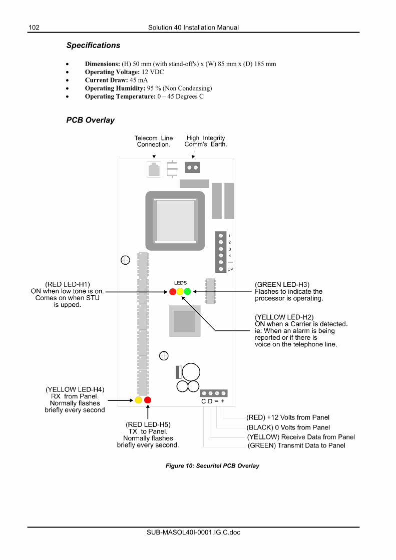
102 Solution 40 Installation Manual
SUB-MASOL40I-0001.IG.C.doc
Specifications
• Dimensions: (H) 50 mm (with stand-off's) x (W) 85 mm x (D) 185 mm • Operating Voltage: 12 VDC • Current Draw: 45 mA • Operating Humidity: 95 % (Non Condensing) • Operating Temperature: 0 – 45 Degrees C
PCB Overlay
Figure 10: Securitel PCB Overlay
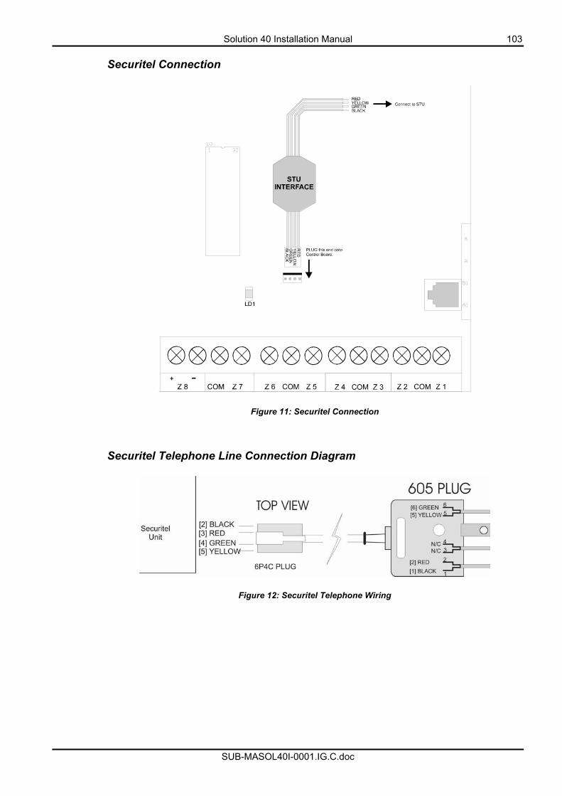
Solution 40 Installation Manual 103
SUB-MASOL40I-0001.IG.C.doc
Securitel Connection
Figure 11: Securitel Connection Securitel Telephone Line Connection Diagram
Figure 12: Securitel Telephone Wiring
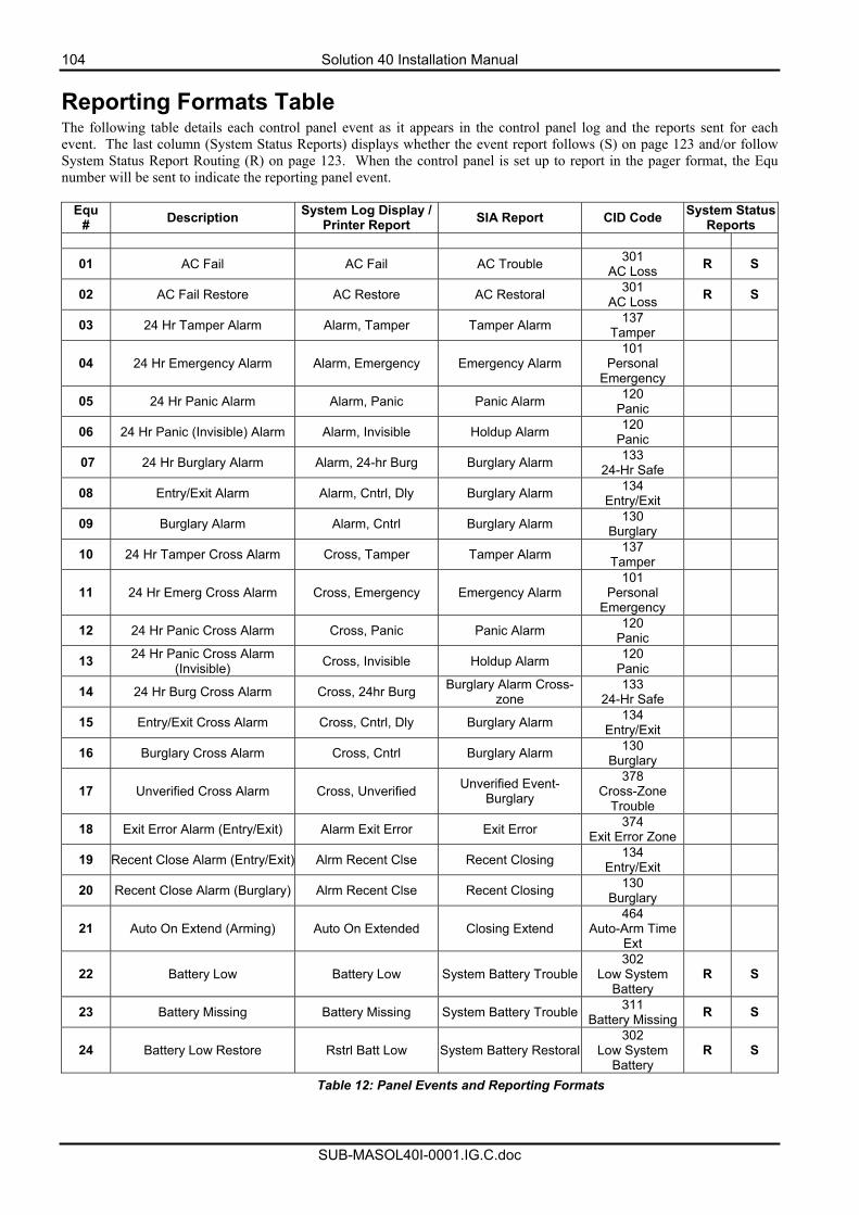
104 Solution 40 Installation Manual
SUB-MASOL40I-0001.IG.C.doc
Reporting Formats Table The following table details each control panel event as it appears in the control panel log and the reports sent for each event. The last column (System Status Reports) displays whether the event report follows (S) on page 123 and/or follow System Status Report Routing (R) on page 123. When the control panel is set up to report in the pager format, the Equ number will be sent to indicate the reporting panel event.
Equ # Description System Log Display /
Printer Report SIA Report CID Code System Status Reports
01 AC Fail AC Fail AC Trouble 301 AC Loss R S
02 AC Fail Restore AC Restore AC Restoral 301 AC Loss R S
03 24 Hr Tamper Alarm Alarm, Tamper Tamper Alarm 137 Tamper
04 24 Hr Emergency Alarm Alarm, Emergency Emergency Alarm 101
Personal Emergency
05 24 Hr Panic Alarm Alarm, Panic Panic Alarm 120 Panic
06 24 Hr Panic (Invisible) Alarm Alarm, Invisible Holdup Alarm 120 Panic
07 24 Hr Burglary Alarm Alarm, 24-hr Burg Burglary Alarm 133 24-Hr Safe
08 Entry/Exit Alarm Alarm, Cntrl, Dly Burglary Alarm 134 Entry/Exit
09 Burglary Alarm Alarm, Cntrl Burglary Alarm 130 Burglary
10 24 Hr Tamper Cross Alarm Cross, Tamper Tamper Alarm 137 Tamper
11 24 Hr Emerg Cross Alarm Cross, Emergency Emergency Alarm 101
Personal Emergency
12 24 Hr Panic Cross Alarm Cross, Panic Panic Alarm 120 Panic
13 24 Hr Panic Cross Alarm (Invisible) Cross, Invisible Holdup Alarm 120
Panic
14 24 Hr Burg Cross Alarm Cross, 24hr Burg Burglary Alarm Cross-zone
133 24-Hr Safe
15 Entry/Exit Cross Alarm Cross, Cntrl, Dly Burglary Alarm 134 Entry/Exit
16 Burglary Cross Alarm Cross, Cntrl Burglary Alarm 130 Burglary
17 Unverified Cross Alarm Cross, Unverified Unverified Event-Burglary
378 Cross-Zone
Trouble
18 Exit Error Alarm (Entry/Exit) Alarm Exit Error Exit Error 374 Exit Error Zone
19 Recent Close Alarm (Entry/Exit) Alrm Recent Clse Recent Closing 134 Entry/Exit
20 Recent Close Alarm (Burglary) Alrm Recent Clse Recent Closing 130 Burglary
21 Auto On Extend (Arming) Auto On Extended Closing Extend 464
Auto-Arm Time Ext
22 Battery Low Battery Low System Battery Trouble302
Low System Battery
R S
23 Battery Missing Battery Missing System Battery Trouble 311 Battery Missing R S
24 Battery Low Restore Rstrl Batt Low System Battery Restoral302
Low System Battery
R S
Table 12: Panel Events and Reporting Formats
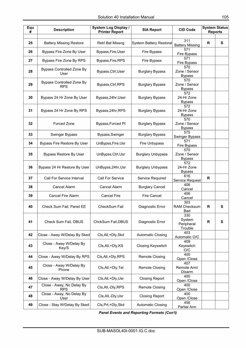
Solution 40 Installation Manual 105
SUB-MASOL40I-0001.IG.C.doc
Equ
# Description System Log Display / Printer Report SIA Report CID Code System Status
Reports
25 Battery Missing Restore Rstrl Bat Missng System Battery Restoral 311 Battery Missing R S
26 Bypass Fire Zone By User Bypass,Fire,User Fire Bypass 571 Fire Bypass
27 Bypass Fire Zone By RPS Bypass,Fire,RPS Fire Bypass 571 Fire Bypass
28 Bypass Controlled Zone By User Bypass,Ctrl,User Burglary Bypass
570 Zone / Sensor
Bypass
29 Bypass Controlled Zone By RPS Bypass,Ctrl,RPS Burglary Bypass
570 Zone / Sensor
Bypass
30 Bypass 24 Hr Zone By User Bypass,24hr,User Burglary Bypass 572
24-Hr Zone Bypass
31 Bypass 24 Hr Zone By RPS Bypass,24hr,RPS Burglary Bypass 572
24-Hr Zone Bypass
32 Forced Zone Bypass,Forced Pt Burglary Bypass 570
Zone / Sensor Bypass
33 Swinger Bypass Bypass,Swinger Burglary Bypass 575 Swinger Bypass
34 Bypass Fire Restore By User UnBypss,Fire,Usr Fire Unbypass 571 Fire Bypass
35 Bypass Restore By User UnBypss,Ctrl,Usr Burglary Unbypass 570
Zone / Sensor Bypass
36 Bypass 24 Hr Restore By User UnBypss,24hr,Usr Burglary Unbypass 572
24-Hr Zone Bypass
37 Call For Service Interval Call For Service Service Required 616 Service Request R
38 Cancel Alarm Cancel Alarm Burglary Cancel 406 Cancel
39 Cancel Fire Alarm Cancel Fire Fire Cancel 406 Cancel
40 Check Sum Fail, Panel EE CheckSum Fail Diagnostic Error 303
RAM Checksum Bad
R S
41 Check Sum Fail, DBUS ChckSum Fail,DBUS Diagnostic Error
330 System
Peripheral Trouble
R S
42 Close - Away W/Delay By Sked Cls,All,+Dly,Skd Automatic Closing 403 Automatic O/C
43 Close - Away W/Delay By Key/S Cls,All,+Dly,KS Closing Keyswitch
409 Keyswitch
O/C
44 Close - Away W/Delay By RPS Cls,All,+Dly,RPS Remote Closing 400 Open /Close
45 Close - Away W/Delay By Phone Cls,All,+Dly,Tel Remote Closing
407 Remote Arm/
Disarm
46 Close - Away W/Delay By User Cls,All,+Dly,Usr Closing Report 400 Open /Close
47 Close - Away, No Delay By RPS Cls,All,-Dly,RPS Remote Closing 400
Open /Close
48 Close - Away, No Delay By User Cls,All,-Dly,Usr Closing Report 400
Open /Close
49 Close - Stay W/Delay By Sked Cls,Prt,+Dly,Skd Automatic Closing 456 Partial Arm
Panel Events and Reporting Formats (Con't)
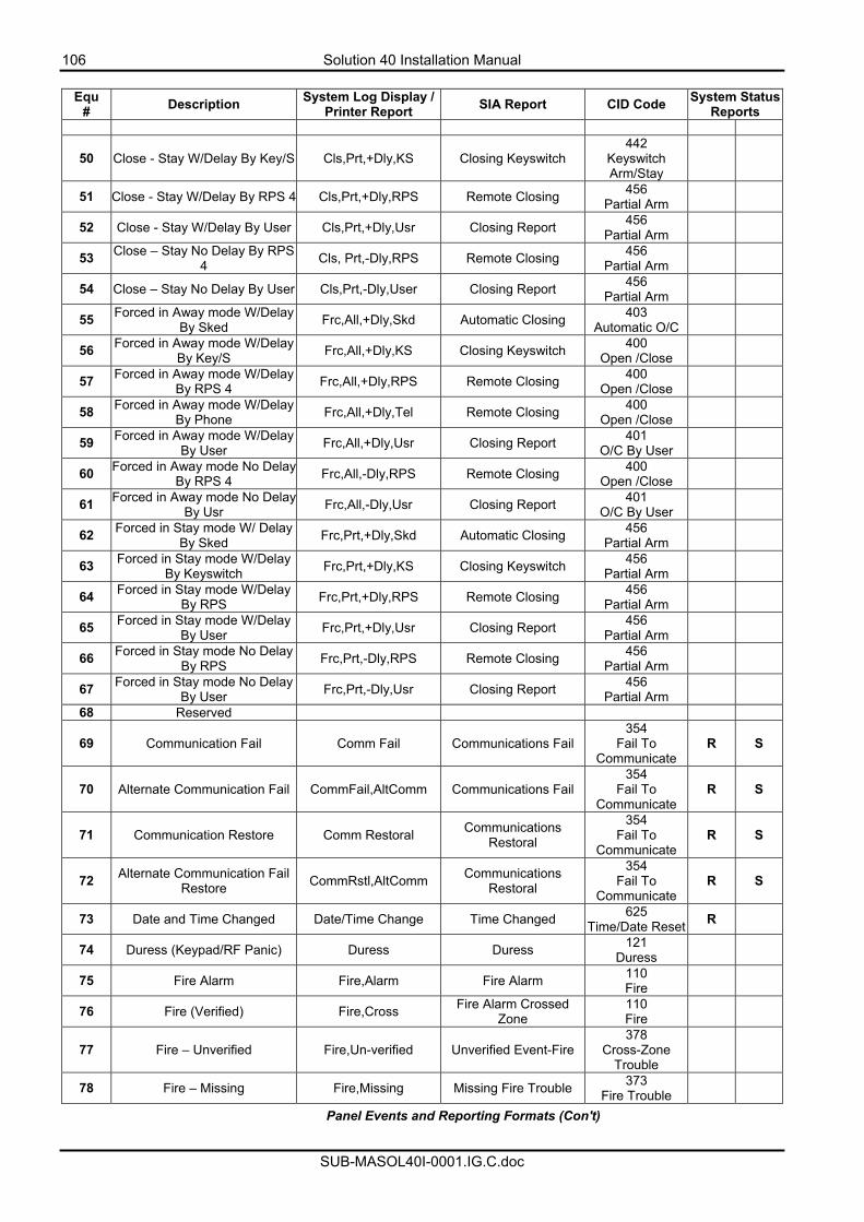
106 Solution 40 Installation Manual
SUB-MASOL40I-0001.IG.C.doc
Equ
# Description System Log Display / Printer Report SIA Report CID Code System Status
Reports
50 Close - Stay W/Delay By Key/S Cls,Prt,+Dly,KS Closing Keyswitch 442
Keyswitch Arm/Stay
51 Close - Stay W/Delay By RPS 4 Cls,Prt,+Dly,RPS Remote Closing 456 Partial Arm
52 Close - Stay W/Delay By User Cls,Prt,+Dly,Usr Closing Report 456 Partial Arm
53 Close – Stay No Delay By RPS 4 Cls, Prt,-Dly,RPS Remote Closing 456
Partial Arm
54 Close – Stay No Delay By User Cls,Prt,-Dly,User Closing Report 456 Partial Arm
55 Forced in Away mode W/Delay By Sked Frc,All,+Dly,Skd Automatic Closing 403
Automatic O/C
56 Forced in Away mode W/Delay By Key/S Frc,All,+Dly,KS Closing Keyswitch 400
Open /Close
57 Forced in Away mode W/Delay By RPS 4 Frc,All,+Dly,RPS Remote Closing 400
Open /Close
58 Forced in Away mode W/Delay By Phone Frc,All,+Dly,Tel Remote Closing 400
Open /Close
59 Forced in Away mode W/Delay By User Frc,All,+Dly,Usr Closing Report 401
O/C By User
60 Forced in Away mode No Delay By RPS 4 Frc,All,-Dly,RPS Remote Closing 400
Open /Close
61 Forced in Away mode No Delay By Usr Frc,All,-Dly,Usr Closing Report 401
O/C By User
62 Forced in Stay mode W/ Delay By Sked Frc,Prt,+Dly,Skd Automatic Closing 456
Partial Arm
63 Forced in Stay mode W/Delay By Keyswitch Frc,Prt,+Dly,KS Closing Keyswitch 456
Partial Arm
64 Forced in Stay mode W/Delay By RPS Frc,Prt,+Dly,RPS Remote Closing 456
Partial Arm
65 Forced in Stay mode W/Delay By User Frc,Prt,+Dly,Usr Closing Report 456
Partial Arm
66 Forced in Stay mode No Delay By RPS Frc,Prt,-Dly,RPS Remote Closing 456
Partial Arm
67 Forced in Stay mode No Delay By User Frc,Prt,-Dly,Usr Closing Report 456
Partial Arm
68 Reserved
69 Communication Fail Comm Fail Communications Fail 354
Fail To Communicate
R S
70 Alternate Communication Fail CommFail,AltComm Communications Fail 354
Fail To Communicate
R S
71 Communication Restore Comm Restoral Communications Restoral
354 Fail To
Communicate R S
72 Alternate Communication Fail Restore CommRstl,AltComm Communications
Restoral
354 Fail To
Communicate R S
73 Date and Time Changed Date/Time Change Time Changed 625 Time/Date Reset R
74 Duress (Keypad/RF Panic) Duress Duress 121 Duress
75 Fire Alarm Fire,Alarm Fire Alarm 110 Fire
76 Fire (Verified) Fire,Cross Fire Alarm Crossed Zone
110 Fire
77 Fire – Unverified Fire,Un-verified Unverified Event-Fire 378
Cross-Zone Trouble
78 Fire – Missing Fire,Missing Missing Fire Trouble 373 Fire Trouble
Panel Events and Reporting Formats (Con't)
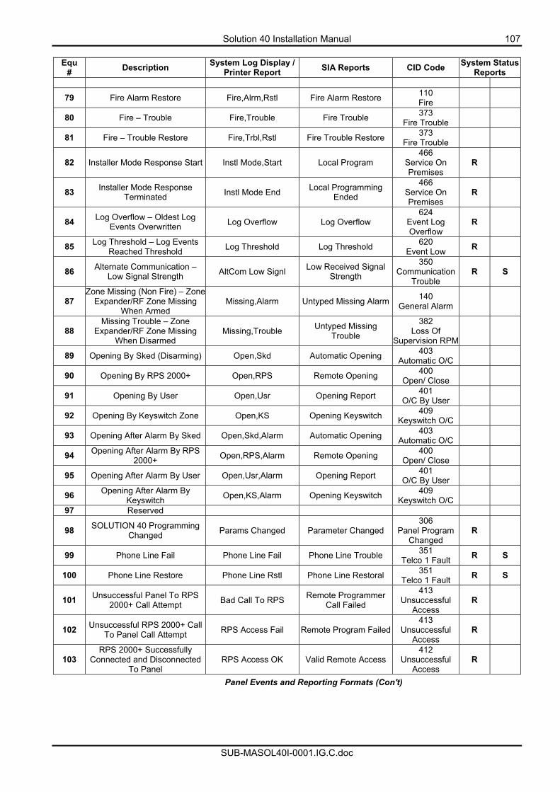
Solution 40 Installation Manual 107
SUB-MASOL40I-0001.IG.C.doc
Equ
# Description System Log Display / Printer Report SIA Reports CID Code System Status
Reports
79 Fire Alarm Restore Fire,Alrm,Rstl Fire Alarm Restore 110 Fire
80 Fire – Trouble Fire,Trouble Fire Trouble 373 Fire Trouble
81 Fire – Trouble Restore Fire,Trbl,Rstl Fire Trouble Restore 373 Fire Trouble
82 Installer Mode Response Start Instl Mode,Start Local Program 466
Service On Premises
R
83 Installer Mode Response Terminated Instl Mode End Local Programming
Ended
466 Service On Premises
R
84 Log Overflow – Oldest Log Events Overwritten Log Overflow Log Overflow
624 Event Log Overflow
R
85 Log Threshold – Log Events Reached Threshold Log Threshold Log Threshold 620
Event Low R
86 Alternate Communication – Low Signal Strength AltCom Low Signl Low Received Signal
Strength
350 Communication
Trouble R S
87 Zone Missing (Non Fire) – Zone
Expander/RF Zone Missing When Armed
Missing,Alarm Untyped Missing Alarm 140 General Alarm
88 Missing Trouble – Zone
Expander/RF Zone Missing When Disarmed
Missing,Trouble Untyped Missing Trouble
382 Loss Of
Supervision RPM
89 Opening By Sked (Disarming) Open,Skd Automatic Opening 403 Automatic O/C
90 Opening By RPS 2000+ Open,RPS Remote Opening 400 Open/ Close
91 Opening By User Open,Usr Opening Report 401 O/C By User
92 Opening By Keyswitch Zone Open,KS Opening Keyswitch 409 Keyswitch O/C
93 Opening After Alarm By Sked Open,Skd,Alarm Automatic Opening 403 Automatic O/C
94 Opening After Alarm By RPS 2000+ Open,RPS,Alarm Remote Opening 400
Open/ Close
95 Opening After Alarm By User Open,Usr,Alarm Opening Report 401 O/C By User
96 Opening After Alarm By Keyswitch Open,KS,Alarm Opening Keyswitch 409
Keyswitch O/C
97 Reserved
98 SOLUTION 40 Programming Changed Params Changed Parameter Changed
306 Panel Program
Changed R
99 Phone Line Fail Phone Line Fail Phone Line Trouble 351 Telco 1 Fault R S
100 Phone Line Restore Phone Line Rstl Phone Line Restoral 351 Telco 1 Fault R S
101 Unsuccessful Panel To RPS 2000+ Call Attempt Bad Call To RPS Remote Programmer
Call Failed
413 Unsuccessful
Access R
102 Unsuccessful RPS 2000+ Call To Panel Call Attempt RPS Access Fail Remote Program Failed
413 Unsuccessful
Access R
103 RPS 2000+ Successfully
Connected and Disconnected To Panel
RPS Access OK Valid Remote Access 412
Unsuccessful Access
R
Panel Events and Reporting Formats (Con't)
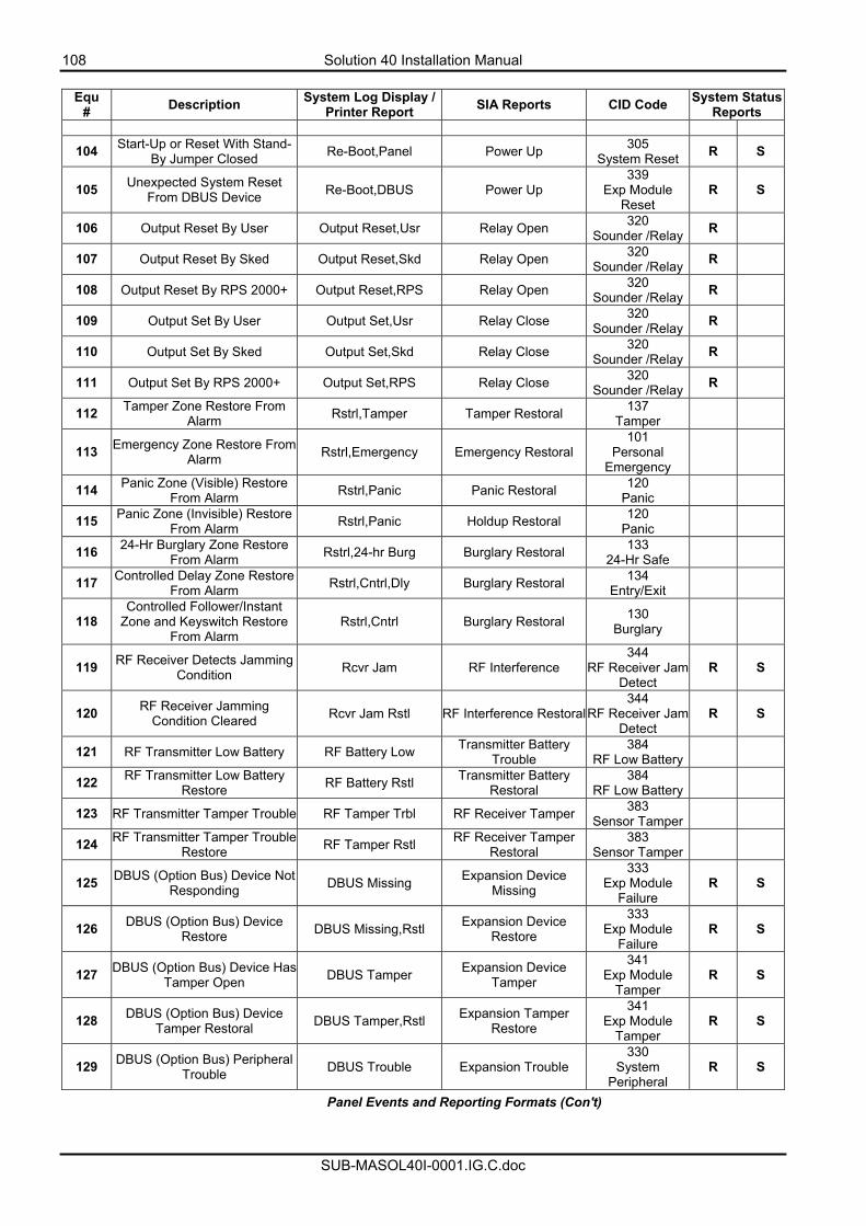
108 Solution 40 Installation Manual
SUB-MASOL40I-0001.IG.C.doc
Equ
# Description System Log Display / Printer Report SIA Reports CID Code System Status
Reports
104 Start-Up or Reset With Stand-By Jumper Closed Re-Boot,Panel Power Up 305
System Reset R S
105 Unexpected System Reset From DBUS Device Re-Boot,DBUS Power Up
339 Exp Module
Reset R S
106 Output Reset By User Output Reset,Usr Relay Open 320 Sounder /Relay R
107 Output Reset By Sked Output Reset,Skd Relay Open 320 Sounder /Relay R
108 Output Reset By RPS 2000+ Output Reset,RPS Relay Open 320 Sounder /Relay R
109 Output Set By User Output Set,Usr Relay Close 320 Sounder /Relay R
110 Output Set By Sked Output Set,Skd Relay Close 320 Sounder /Relay R
111 Output Set By RPS 2000+ Output Set,RPS Relay Close 320 Sounder /Relay R
112 Tamper Zone Restore From Alarm Rstrl,Tamper Tamper Restoral 137
Tamper
113 Emergency Zone Restore From Alarm Rstrl,Emergency Emergency Restoral
101 Personal
Emergency
114 Panic Zone (Visible) Restore From Alarm Rstrl,Panic Panic Restoral 120
Panic
115 Panic Zone (Invisible) Restore From Alarm Rstrl,Panic Holdup Restoral 120
Panic
116 24-Hr Burglary Zone Restore From Alarm Rstrl,24-hr Burg Burglary Restoral 133
24-Hr Safe
117 Controlled Delay Zone Restore From Alarm Rstrl,Cntrl,Dly Burglary Restoral 134
Entry/Exit
118 Controlled Follower/Instant
Zone and Keyswitch Restore From Alarm
Rstrl,Cntrl Burglary Restoral 130 Burglary
119 RF Receiver Detects Jamming Condition Rcvr Jam RF Interference
344 RF Receiver Jam
Detect R S
120 RF Receiver Jamming Condition Cleared Rcvr Jam Rstl RF Interference Restoral
344 RF Receiver Jam
Detect R S
121 RF Transmitter Low Battery RF Battery Low Transmitter Battery Trouble
384 RF Low Battery
122 RF Transmitter Low Battery Restore RF Battery Rstl Transmitter Battery
Restoral 384
RF Low Battery
123 RF Transmitter Tamper Trouble RF Tamper Trbl RF Receiver Tamper 383 Sensor Tamper
124 RF Transmitter Tamper Trouble Restore RF Tamper Rstl RF Receiver Tamper
Restoral 383
Sensor Tamper
125 DBUS (Option Bus) Device Not Responding DBUS Missing Expansion Device
Missing
333 Exp Module
Failure R S
126 DBUS (Option Bus) Device Restore DBUS Missing,Rstl Expansion Device
Restore
333 Exp Module
Failure R S
127 DBUS (Option Bus) Device Has Tamper Open DBUS Tamper Expansion Device
Tamper
341 Exp Module
Tamper R S
128 DBUS (Option Bus) Device Tamper Restoral DBUS Tamper,Rstl Expansion Tamper
Restore
341 Exp Module
Tamper R S
129 DBUS (Option Bus) Peripheral Trouble DBUS Trouble Expansion Trouble
330 System
Peripheral R S
Panel Events and Reporting Formats (Con't)
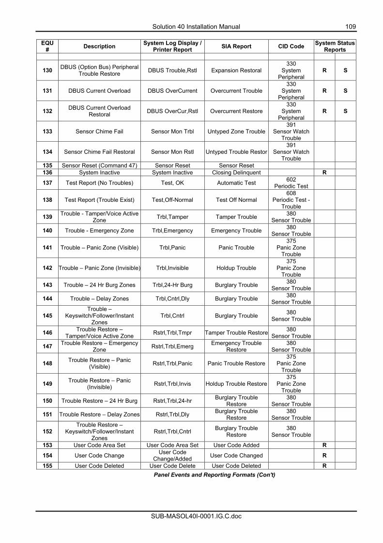
Solution 40 Installation Manual 109
SUB-MASOL40I-0001.IG.C.doc
EQU
# Description System Log Display / Printer Report SIA Report CID Code System Status
Reports
130 DBUS (Option Bus) Peripheral Trouble Restore DBUS Trouble,Rstl Expansion Restoral
330 System
Peripheral R S
131 DBUS Current Overload DBUS OverCurrent Overcurrent Trouble 330
System Peripheral
R S
132 DBUS Current Overload Restoral DBUS OverCur,Rstl Overcurrent Restore
330 System
Peripheral R S
133 Sensor Chime Fail Sensor Mon Trbl Untyped Zone Trouble391
Sensor Watch Trouble
134 Sensor Chime Fail Restoral Sensor Mon Rstl Untyped Trouble Restor391
Sensor Watch Trouble
135 Sensor Reset (Command 47) Sensor Reset Sensor Reset 136 System Inactive System Inactive Closing Delinquent R
137 Test Report (No Troubles) Test, OK Automatic Test 602 Periodic Test
138 Test Report (Trouble Exist) Test,Off-Normal Test Off Normal 608
Periodic Test - Trouble
139 Trouble - Tamper/Voice Active Zone Trbl,Tamper Tamper Trouble 380
Sensor Trouble
140 Trouble - Emergency Zone Trbl,Emergency Emergency Trouble 380 Sensor Trouble
141 Trouble – Panic Zone (Visible) Trbl,Panic Panic Trouble 375
Panic Zone Trouble
142 Trouble – Panic Zone (Invisible) Trbl,Invisible Holdup Trouble 375
Panic Zone Trouble
143 Trouble – 24 Hr Burg Zones Trbl,24-Hr Burg Burglary Trouble 380 Sensor Trouble
144 Trouble – Delay Zones Trbl,Cntrl,Dly Burglary Trouble 380 Sensor Trouble
145 Trouble –
Keyswitch/Follower/Instant Zones
Trbl,Cntrl Burglary Trouble 380 Sensor Trouble
146 Trouble Restore – Tamper/Voice Active Zone Rstrl,Trbl,Tmpr Tamper Trouble Restore 380
Sensor Trouble
147 Trouble Restore – Emergency Zone Rstrl,Trbl,Emerg Emergency Trouble
Restore 380
Sensor Trouble
148 Trouble Restore – Panic (Visible) Rstrl,Trbl,Panic Panic Trouble Restore
375 Panic Zone
Trouble
149 Trouble Restore – Panic (Invisible) Rstrl,Trbl,Invis Holdup Trouble Restore
375 Panic Zone
Trouble
150 Trouble Restore – 24 Hr Burg Rstrl,Trbl,24-hr Burglary Trouble Restore
380 Sensor Trouble
151 Trouble Restore – Delay Zones Rstrl,Trbl,Dly Burglary Trouble Restore
380 Sensor Trouble
152 Trouble Restore –
Keyswitch/Follower/Instant Zones
Rstrl,Trbl,Cntrl Burglary Trouble Restore
380 Sensor Trouble
153 User Code Area Set User Code Area Set User Code Added R
154 User Code Change User Code Change/Added User Code Changed R
155 User Code Deleted User Code Delete User Code Deleted R Panel Events and Reporting Formats (Con't)
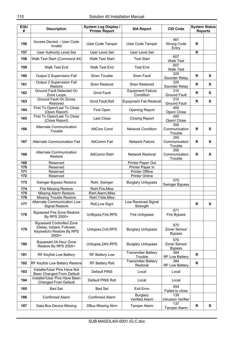
110 Solution 40 Installation Manual
SUB-MASOL40I-0001.IG.C.doc
EQU
# Description System Log Display / Printer Report SIA Report CID Code System Status
Reports
156 Access Denied – User Code Invalid User Code Tamper User Code Tamper
461 Wrong Code
Entry R
157 User Authority Level Set User Level Set User Level Set R
158 Walk Test Start (Command 44) Walk Test Start Test Start 607 Walk Test
159 Walk Test End Walk Test End Test End 607 Walk Test
160 Output 2 Supervision Fail Siren Trouble Siren Fault 320 Sounder Relay R S
161 Output 2 Supervision Fail Restore Siren Restoral Siren Restored 320
Sounder Relay R S
162 Ground Fault Detected On Zone Loops Grnd Fault Equipment Failure
Condition 310
Ground Fault R S
163 Ground Fault On Zones Restored Grnd Fault,Rstl Equipment Fail Restoral 310
Ground Fault R S
164 First To Open/Last To Close (Open Report) First Open Opening Report 400
Open/ Close
165 First To Open/Last To Close (Close Report) Last Close Closing Report 400
Open/ Close
166 Alternate Communication Trouble AltCom Cond Network Condition
350 Communication
Trouble R S
167 Alternate Communication Fail AltComm Fail Network Failure 350
Communication Trouble
R S
168 Alternate Communication Restore AltComm Rstrl Network Restoral
350 Communication
Trouble R S
169 Reserved Printer Paper Out 170 Reserved Printer Paper In 171 Reserved Printer Offline 172 Reserved Printer Online
173 Swinger Bypass Restore Rstrl, Swinger Burglary Unbypass 575 Swinger Bypass
174 Fire Missing Restore Rstrl,Fire,Miss 175 Missing Alarm Restore Rstrl,Alarm,Miss 176 Missing Trouble Restore Rstrl,Trble,Miss
177 Alternate Communication Low Signal Restore Rstl,Low Signl Low Received Signal
Strength R S
178 Bypassed Fire Zone Restore By RPS 2000+ UnBypss,Fire,RPS Fire Unbypass
571 Fire Bypass
179 Bypassed Controlled Zone (Delay, Instant, Follower,
Keyswitch) Restore By RPS 2000+
Unbypss,Cntl,RPS Burglary Unbypass 570
Zone/ Sensor Bypass
180 Bypassed 24-Hour Zone Restore By RPS 2000+ Unbypss,24hr,RPS Burglary Unbypass
570 Zone/ Sensor
Bypass
181 RF Keyfob Low Battery RF Battery Low Transmitter Battery Trouble
384 RF Low Battery R
182 RF Keyfob Low Battery Restore RF Battery Rstl Transmitter Battery Restoral
384 RF Low Battery R
183 Installer/User Pins Have Not Been Changed From Default Default PINS Local Local
184 Installer/User Pins Have Been Changed From Default Default PINS Rstl Local Local
185 Bad Set Bad Set Exit Error 454 Failed to close
186 Confirmed Alarm Confirmed Alarm Burglary Verified Alarm
139 Intrusion Verifier
187 Data Bus Device Missing DBus Missing Alrm Tamper Alarm 137 Tamper Alarm R S
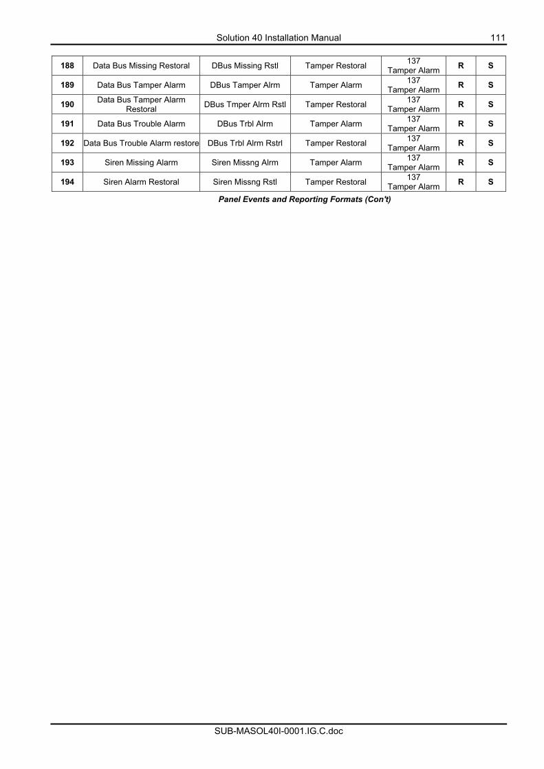
Solution 40 Installation Manual 111
SUB-MASOL40I-0001.IG.C.doc
188 Data Bus Missing Restoral DBus Missing Rstl Tamper Restoral 137
Tamper Alarm R S
189 Data Bus Tamper Alarm DBus Tamper Alrm Tamper Alarm 137 Tamper Alarm R S
190 Data Bus Tamper Alarm Restoral DBus Tmper Alrm Rstl Tamper Restoral 137
Tamper Alarm R S
191 Data Bus Trouble Alarm DBus Trbl Alrm Tamper Alarm 137 Tamper Alarm R S
192 Data Bus Trouble Alarm restore DBus Trbl Alrm Rstrl Tamper Restoral 137 Tamper Alarm R S
193 Siren Missing Alarm Siren Missng Alrm Tamper Alarm 137 Tamper Alarm R S
194 Siren Alarm Restoral Siren Missng Rstl Tamper Restoral 137 Tamper Alarm R S
Panel Events and Reporting Formats (Con't)
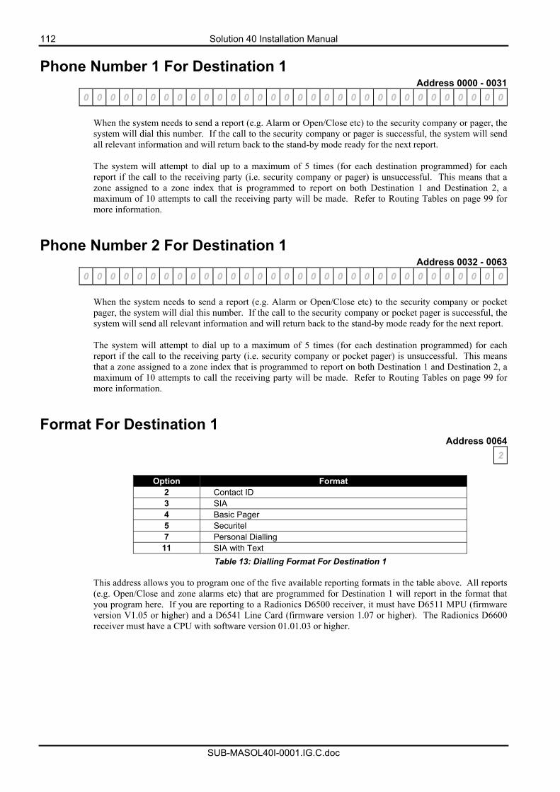
112 Solution 40 Installation Manual
SUB-MASOL40I-0001.IG.C.doc
Phone Number 1 For Destination 1 Address 0000 - 0031
0 0 0 0 0 0 0 0 0 0 0 0 0 0 0 0 0 0 0 0 0 0 0 0 0 0 0 0 0 0 0 0
When the system needs to send a report (e.g. Alarm or Open/Close etc) to the security company or pager, the system will dial this number. If the call to the security company or pager is successful, the system will send all relevant information and will return back to the stand-by mode ready for the next report. The system will attempt to dial up to a maximum of 5 times (for each destination programmed) for each report if the call to the receiving party (i.e. security company or pager) is unsuccessful. This means that a zone assigned to a zone index that is programmed to report on both Destination 1 and Destination 2, a maximum of 10 attempts to call the receiving party will be made. Refer to Routing Tables on page 99 for more information.
Phone Number 2 For Destination 1 Address 0032 - 0063
0 0 0 0 0 0 0 0 0 0 0 0 0 0 0 0 0 0 0 0 0 0 0 0 0 0 0 0 0 0 0 0
When the system needs to send a report (e.g. Alarm or Open/Close etc) to the security company or pocket pager, the system will dial this number. If the call to the security company or pocket pager is successful, the system will send all relevant information and will return back to the stand-by mode ready for the next report. The system will attempt to dial up to a maximum of 5 times (for each destination programmed) for each report if the call to the receiving party (i.e. security company or pocket pager) is unsuccessful. This means that a zone assigned to a zone index that is programmed to report on both Destination 1 and Destination 2, a maximum of 10 attempts to call the receiving party will be made. Refer to Routing Tables on page 99 for more information.
Format For Destination 1 Address 0064
2
Option Format 2 Contact ID 3 SIA 4 Basic Pager 5 Securitel 7 Personal Dialling
11 SIA with Text Table 13: Dialling Format For Destination 1
This address allows you to program one of the five available reporting formats in the table above. All reports (e.g. Open/Close and zone alarms etc) that are programmed for Destination 1 will report in the format that you program here. If you are reporting to a Radionics D6500 receiver, it must have D6511 MPU (firmware version V1.05 or higher) and a D6541 Line Card (firmware version 1.07 or higher). The Radionics D6600 receiver must have a CPU with software version 01.01.03 or higher.
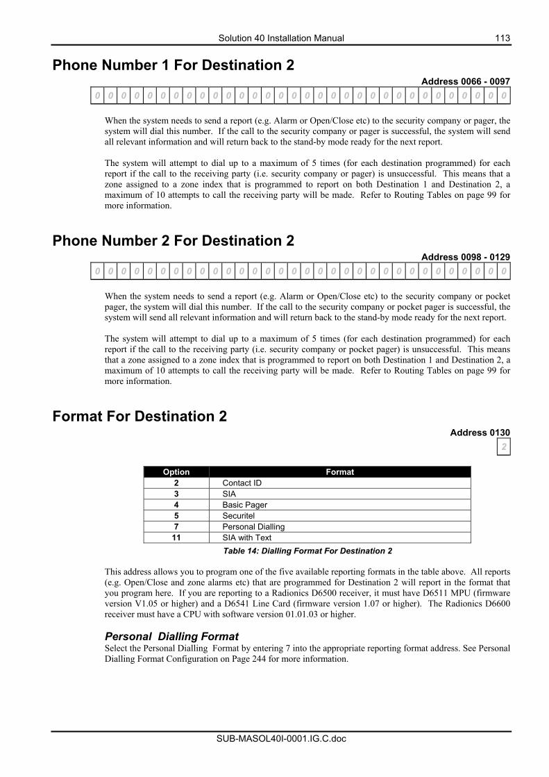
Solution 40 Installation Manual 113
SUB-MASOL40I-0001.IG.C.doc
Phone Number 1 For Destination 2 Address 0066 - 0097
0 0 0 0 0 0 0 0 0 0 0 0 0 0 0 0 0 0 0 0 0 0 0 0 0 0 0 0 0 0 0 0
When the system needs to send a report (e.g. Alarm or Open/Close etc) to the security company or pager, the system will dial this number. If the call to the security company or pager is successful, the system will send all relevant information and will return back to the stand-by mode ready for the next report. The system will attempt to dial up to a maximum of 5 times (for each destination programmed) for each report if the call to the receiving party (i.e. security company or pager) is unsuccessful. This means that a zone assigned to a zone index that is programmed to report on both Destination 1 and Destination 2, a maximum of 10 attempts to call the receiving party will be made. Refer to Routing Tables on page 99 for more information.
Phone Number 2 For Destination 2 Address 0098 - 0129
0 0 0 0 0 0 0 0 0 0 0 0 0 0 0 0 0 0 0 0 0 0 0 0 0 0 0 0 0 0 0 0
When the system needs to send a report (e.g. Alarm or Open/Close etc) to the security company or pocket pager, the system will dial this number. If the call to the security company or pocket pager is successful, the system will send all relevant information and will return back to the stand-by mode ready for the next report. The system will attempt to dial up to a maximum of 5 times (for each destination programmed) for each report if the call to the receiving party (i.e. security company or pocket pager) is unsuccessful. This means that a zone assigned to a zone index that is programmed to report on both Destination 1 and Destination 2, a maximum of 10 attempts to call the receiving party will be made. Refer to Routing Tables on page 99 for more information.
Format For Destination 2 Address 0130
2
Option Format 2 Contact ID 3 SIA 4 Basic Pager 5 Securitel 7 Personal Dialling
11 SIA with Text Table 14: Dialling Format For Destination 2
This address allows you to program one of the five available reporting formats in the table above. All reports (e.g. Open/Close and zone alarms etc) that are programmed for Destination 2 will report in the format that you program here. If you are reporting to a Radionics D6500 receiver, it must have D6511 MPU (firmware version V1.05 or higher) and a D6541 Line Card (firmware version 1.07 or higher). The Radionics D6600 receiver must have a CPU with software version 01.01.03 or higher. Personal Dialling Format Select the Personal Dialling Format by entering 7 into the appropriate reporting format address. See Personal Dialling Format Configuration on Page 244 for more information.
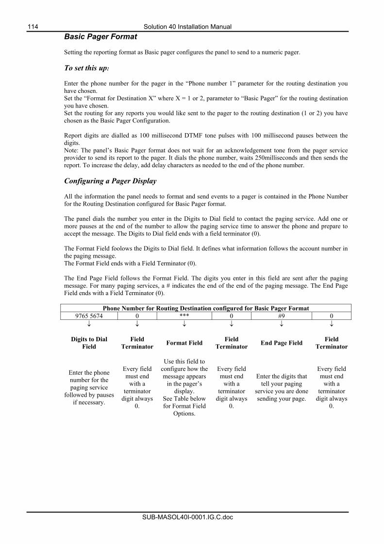
114 Solution 40 Installation Manual
SUB-MASOL40I-0001.IG.C.doc
Basic Pager Format Setting the reporting format as Basic pager configures the panel to send to a numeric pager. To set this up: Enter the phone number for the pager in the “Phone number 1” parameter for the routing destination you have chosen. Set the “Format for Destination X” where X = 1 or 2, parameter to “Basic Pager” for the routing destination you have chosen. Set the routing for any reports you would like sent to the pager to the routing destination (1 or 2) you have chosen as the Basic Pager Configuration. Report digits are dialled as 100 millisecond DTMF tone pulses with 100 millisecond pauses between the digits. Note: The panel’s Basic Pager format does not wait for an acknowledgement tone from the pager service provider to send its report to the pager. It dials the phone number, waits 250milliseconds and then sends the report. To increase the delay, add delay characters as needed to the end of the phone number. Configuring a Pager Display All the information the panel needs to format and send events to a pager is contained in the Phone Number for the Routing Destination configured for Basic Pager format. The panel dials the number you enter in the Digits to Dial field to contact the paging service. Add one or more pauses at the end of the number to allow the paging service time to answer the phone and prepare to accept the message. The Digits to Dial field ends with a field terminator (0). The Format Field foolows the Digits to Dial field. It defines what information follows the account number in the paging message. The Format Field ends with a Field Terminator (0). The End Page Field follows the Format Field. The digits you enter in this field are sent after the paging message. For many paging services, a # indicates the end of the end of the paging message. The End Page Field ends with a Field Terminator (0).
Phone Number for Routing Destination configured for Basic Pager Format 9765 5674 0 *** 0 #9 0
↓ ↓ ↓ ↓ ↓ ↓
Digits to Dial Field
Field Terminator Format Field Field
Terminator End Page Field Field Terminator
Enter the phone number for the paging service
followed by pauses if necessary.
Every field must end
with a terminator
digit always 0.
Use this field to configure how the message appears
in the pager’s display.
See Table below for Format Field
Options.
Every field must end
with a terminator
digit always 0.
Enter the digits that tell your paging
service you are done sending your page.
Every field must end
with a terminator
digit always 0.
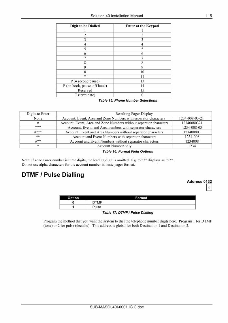
Solution 40 Installation Manual 115
SUB-MASOL40I-0001.IG.C.doc
Digit to be Dialled Enter at the Keypad
1 1 2 2 3 3 4 4 5 5 6 6 7 7 8 8 9 9 0 10 * 11
P (4 second pause) 13 F (on hook, pause, off hook) 14
Reserved 15 T (terminate) 0
Table 15: Phone Number Selections
Digits to Enter Resulting Pager Display None Account, Event, Area and Zone Numbers with separator characters 1234-008-03-21
# Account, Event, Area and Zone Numbers without separator characters 12340080321 *** Account, Event, and Area numbers with separator characters 1234-008-03 #*** Account, Event and Area Numbers without separator characters 123400803 ** Account and Event Numbers with separator characters 1234-008
#** Account and Event Numbers without separator characters 1234008 * Account Number only 1234
Table 16: Format Field Options Note: If zone / user number is three digits, the leading digit is omitted. E.g. “252” displays as “52”. Do not use alpha characters for the account number in basic pager format.
DTMF / Pulse Dialling Address 0132
0
Option Format 0 DTMF 1 Pulse
Table 17: DTMF / Pulse Dialling
Program the method that you want the system to dial the telephone number digits here. Program 1 for DTMF (tone) or 2 for pulse (decadic). This address is global for both Destination 1 and Destination 2.
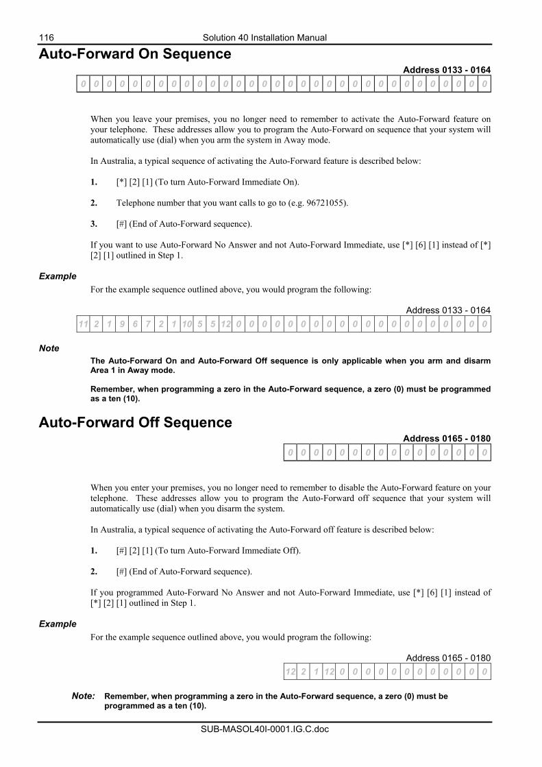
116 Solution 40 Installation Manual
SUB-MASOL40I-0001.IG.C.doc
Auto-Forward On Sequence Address 0133 - 0164
0 0 0 0 0 0 0 0 0 0 0 0 0 0 0 0 0 0 0 0 0 0 0 0 0 0 0 0 0 0 0 0
When you leave your premises, you no longer need to remember to activate the Auto-Forward feature on your telephone. These addresses allow you to program the Auto-Forward on sequence that your system will automatically use (dial) when you arm the system in Away mode. In Australia, a typical sequence of activating the Auto-Forward feature is described below: 1. [*] [2] [1] (To turn Auto-Forward Immediate On).
2. Telephone number that you want calls to go to (e.g. 96721055).
3. [#] (End of Auto-Forward sequence).
If you want to use Auto-Forward No Answer and not Auto-Forward Immediate, use [*] [6] [1] instead of [*] [2] [1] outlined in Step 1.
Example For the example sequence outlined above, you would program the following:
Address 0133 - 0164 11 2 1 9 6 7 2 1 10 5 5 12 0 0 0 0 0 0 0 0 0 0 0 0 0 0 0 0 0 0 0 0
Note
The Auto-Forward On and Auto-Forward Off sequence is only applicable when you arm and disarm Area 1 in Away mode. Remember, when programming a zero in the Auto-Forward sequence, a zero (0) must be programmed as a ten (10).
Auto-Forward Off Sequence Address 0165 - 0180
0 0 0 0 0 0 0 0 0 0 0 0 0 0 0 0 When you enter your premises, you no longer need to remember to disable the Auto-Forward feature on your telephone. These addresses allow you to program the Auto-Forward off sequence that your system will automatically use (dial) when you disarm the system. In Australia, a typical sequence of activating the Auto-Forward off feature is described below: 1. [#] [2] [1] (To turn Auto-Forward Immediate Off).
2. [#] (End of Auto-Forward sequence).
If you programmed Auto-Forward No Answer and not Auto-Forward Immediate, use [*] [6] [1] instead of [*] [2] [1] outlined in Step 1.
Example For the example sequence outlined above, you would program the following:
Address 0165 - 0180 12 2 1 12 0 0 0 0 0 0 0 0 0 0 0 0
Note: Remember, when programming a zero in the Auto-Forward sequence, a zero (0) must be
programmed as a ten (10).
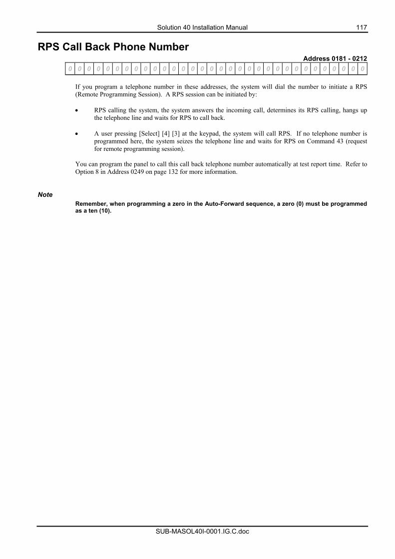
Solution 40 Installation Manual 117
SUB-MASOL40I-0001.IG.C.doc
RPS Call Back Phone Number Address 0181 - 0212
0 0 0 0 0 0 0 0 0 0 0 0 0 0 0 0 0 0 0 0 0 0 0 0 0 0 0 0 0 0 0 0
If you program a telephone number in these addresses, the system will dial the number to initiate a RPS (Remote Programming Session). A RPS session can be initiated by:
• RPS calling the system, the system answers the incoming call, determines its RPS calling, hangs up
the telephone line and waits for RPS to call back.
• A user pressing [Select] [4] [3] at the keypad, the system will call RPS. If no telephone number is programmed here, the system seizes the telephone line and waits for RPS on Command 43 (request for remote programming session).
You can program the panel to call this call back telephone number automatically at test report time. Refer to Option 8 in Address 0249 on page 132 for more information.
Note
Remember, when programming a zero in the Auto-Forward sequence, a zero (0) must be programmed as a ten (10).
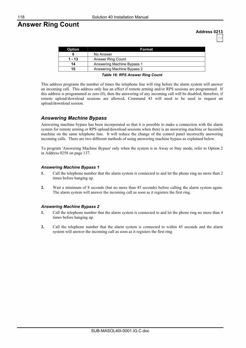
118 Solution 40 Installation Manual
SUB-MASOL40I-0001.IG.C.doc
Answer Ring Count Address 0213
15
Option Format 0 No Answer
1 - 13 Answer Ring Count 14 Answering Machine Bypass 1 15 Answering Machine Bypass 2
Table 18: RPS Answer Ring Count
This address programs the number of times the telephone line will ring before the alarm system will answer an incoming call. This address only has an effect if remote arming and/or RPS sessions are programmed. If this address is programmed as zero (0), then the answering of any incoming call will be disabled, therefore, if remote upload/download sessions are allowed, Command 43 will need to be used to request an upload/download session. Answering Machine Bypass Answering machine bypass has been incorporated so that it is possible to make a connection with the alarm system for remote arming or RPS upload/download sessions when there is an answering machine or facsimile machine on the same telephone line. It will reduce the change of the control panel incorrectly answering incoming calls. There are two different methods of using answering machine bypass as explained below. To program 'Answering Machine Bypass' only when the system is in Away or Stay mode, refer to Option 2 in Address 0258 on page 137. Answering Machine Bypass 1 1. Call the telephone number that the alarm system is connected to and let the phone ring no more than 2
times before hanging up.
2. Wait a minimum of 8 seconds (but no more than 45 seconds) before calling the alarm system again. The alarm system will answer the incoming call as soon as it registers the first ring.
Answering Machine Bypass 2 1. Call the telephone number that the alarm system is connected to and let the phone ring no more than 4
times before hanging up. 2. Call the telephone number that the alarm system is connected to within 45 seconds and the alarm
system will answer the incoming call as soon as it registers the first ring.
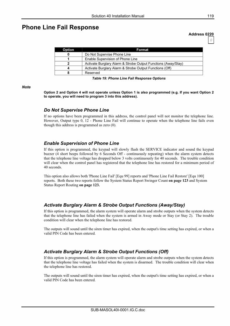
Solution 40 Installation Manual 119
SUB-MASOL40I-0001.IG.C.doc
Phone Line Fail Response Address 0220
0
Option Format 0 Do Not Supervise Phone Line 1 Enable Supervision of Phone Line 2 Activate Burglary Alarm & Strobe Output Functions (Away/Stay) 4 Activate Burglary Alarm & Strobe Output Functions (Off) 8 Reserved
Table 19: Phone Line Fail Response Options Note
Option 2 and Option 4 will not operate unless Option 1 is also programmed (e.g. If you want Option 2 to operate, you will need to program 3 into this address).
Do Not Supervise Phone Line If no options have been programmed in this address, the control panel will not monitor the telephone line. However, Output type 0, 12 - Phone Line Fail will continue to operate when the telephone line fails even though this address is programmed as zero (0). Enable Supervision of Phone Line If this option is programmed, the keypad will slowly flash the SERVICE indicator and sound the keypad buzzer (4 short beeps followed by 6 Seconds Off - continuously repeating) when the alarm system detects that the telephone line voltage has dropped below 3 volts continuously for 40 seconds. The trouble condition will clear when the control panel has registered that the telephone line has restored for a minimum period of 40 seconds. This option also allows both 'Phone Line Fail' [Equ 99] reports and 'Phone Line Fail Restore' [Equ 100] reports. Both these two reports follow the System Status Report Swinger Count on page 123 and System Status Report Routing on page 123.
Activate Burglary Alarm & Strobe Output Functions (Away/Stay) If this option is programmed, the alarm system will operate alarm and strobe outputs when the system detects that the telephone line has failed when the system is armed in Away mode or Stay (or Stay 2). The trouble condition will clear when the telephone line has restored. The outputs will sound until the siren timer has expired, when the output's time setting has expired, or when a valid PIN Code has been entered.
Activate Burglary Alarm & Strobe Output Functions (Off) If this option is programmed, the alarm system will operate alarm and strobe outputs when the system detects that the telephone line voltage has failed when the system is disarmed. The trouble condition will clear when the telephone line has restored. The outputs will sound until the siren timer has expired, when the output's time setting has expired, or when a valid PIN Code has been entered.
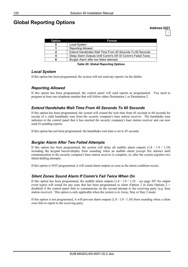
120 Solution 40 Installation Manual
SUB-MASOL40I-0001.IG.C.doc
Global Reporting Options Address 0221
1
Option Format 0 Local System 1 Reporting Allowed 2 Extend Handshake Wait Time From 45 Seconds To 60 Seconds 4 Delay Alarm Outputs Until Comm's OK Or Comm's Failed Twice 8 Burglar Alarm after two failed attempts
Table 20: Global Reporting Options
Local System If this option has been programmed, the system will not send any reports via the dialler. Reporting Allowed If this option has been programmed, the control panel will send reports as programmed. You need to program at least one telephone number that will follow either Destination 1 or Destination 2. Extend Handshake Wait Time From 45 Seconds To 60 Seconds If this option has been programmed, the system will extend the wait time from 45 seconds to 60 seconds for receipt of a valid handshake tone from the security company's base station receiver. The handshake tone indicates to the control panel that it has reached the security company's base station receiver and can now send it's pending reports. If this option has not been programmed, the handshake wait time is set to 45 seconds. Burglar Alarm After Two Failed Attempts If this option has been programmed, the system will delay all audible alarm outputs (1,8 / 1,9 / 1,10) including the keypad buzzer/display from sounding when an audible alarm (except fire alarms) until communication to the security company's base station receiver is complete, or, after the system registers two failed dialling attempts. If this option is NOT programmed, it will sound alarm outputs as soon as the alarm condition occurs.
Silent Zones Sound Alarm If Comm's Fail Twice When On If this option has been programmed, the audible alarm outputs (1,8 / 1,9 / 1,10 – see page 207 for output event types) will sound for any zone that has been programmed as silent (Option 2 in Zone Options 2 = disabled) if the control panel fails to communicate on the second attempt to the receiving party (e.g. base station receiver). This option is only applicable when the system is in Away, Stay or Stay 2 mode. If this option is not programmed, it will prevent alarm outputs (1,8 / 1,9 / 1,10) from sounding when a silent zone fails to report to the receiving party.
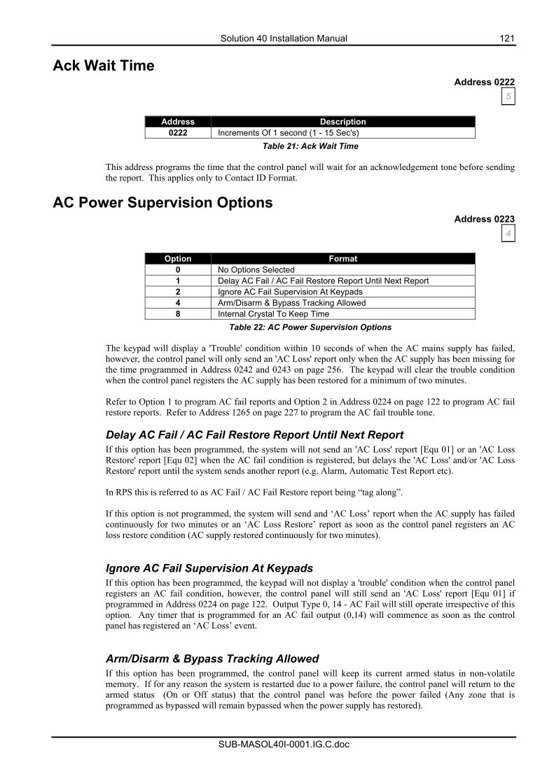
Solution 40 Installation Manual 121
SUB-MASOL40I-0001.IG.C.doc
Ack Wait Time Address 0222
5
Address Description 0222 Increments Of 1 second (1 - 15 Sec's)
Table 21: Ack Wait Time
This address programs the time that the control panel will wait for an acknowledgement tone before sending the report. This applies only to Contact ID Format.
AC Power Supervision Options Address 0223
4
Option Format 0 No Options Selected 1 Delay AC Fail / AC Fail Restore Report Until Next Report 2 Ignore AC Fail Supervision At Keypads 4 Arm/Disarm & Bypass Tracking Allowed 8 Internal Crystal To Keep Time
Table 22: AC Power Supervision Options
The keypad will display a 'Trouble' condition within 10 seconds of when the AC mains supply has failed, however, the control panel will only send an 'AC Loss' report only when the AC supply has been missing for the time programmed in Address 0242 and 0243 on page 256. The keypad will clear the trouble condition when the control panel registers the AC supply has been restored for a minimum of two minutes. Refer to Option 1 to program AC fail reports and Option 2 in Address 0224 on page 122 to program AC fail restore reports. Refer to Address 1265 on page 227 to program the AC fail trouble tone. Delay AC Fail / AC Fail Restore Report Until Next Report If this option has been programmed, the system will not send an 'AC Loss' report [Equ 01] or an 'AC Loss Restore' report [Equ 02] when the AC fail condition is registered, but delays the 'AC Loss' and/or 'AC Loss Restore' report until the system sends another report (e.g. Alarm, Automatic Test Report etc). In RPS this is referred to as AC Fail / AC Fail Restore report being “tag along”. If this option is not programmed, the system will send and ‘AC Loss’ report when the AC supply has failed continuously for two minutes or an ‘AC Loss Restore’ report as soon as the control panel registers an AC loss restore condition (AC supply restored continuously for two minutes). Ignore AC Fail Supervision At Keypads If this option has been programmed, the keypad will not display a 'trouble' condition when the control panel registers an AC fail condition, however, the control panel will still send an 'AC Loss' report [Equ 01] if programmed in Address 0224 on page 122. Output Type 0, 14 - AC Fail will still operate irrespective of this option. Any timer that is programmed for an AC fail output (0,14) will commence as soon as the control panel has registered an ‘AC Loss’ event. Arm/Disarm & Bypass Tracking Allowed If this option has been programmed, the control panel will keep its current armed status in non-volatile memory. If for any reason the system is restarted due to a power failure, the control panel will return to the armed status (On or Off status) that the control panel was before the power failed (Any zone that is programmed as bypassed will remain bypassed when the power supply has restored).
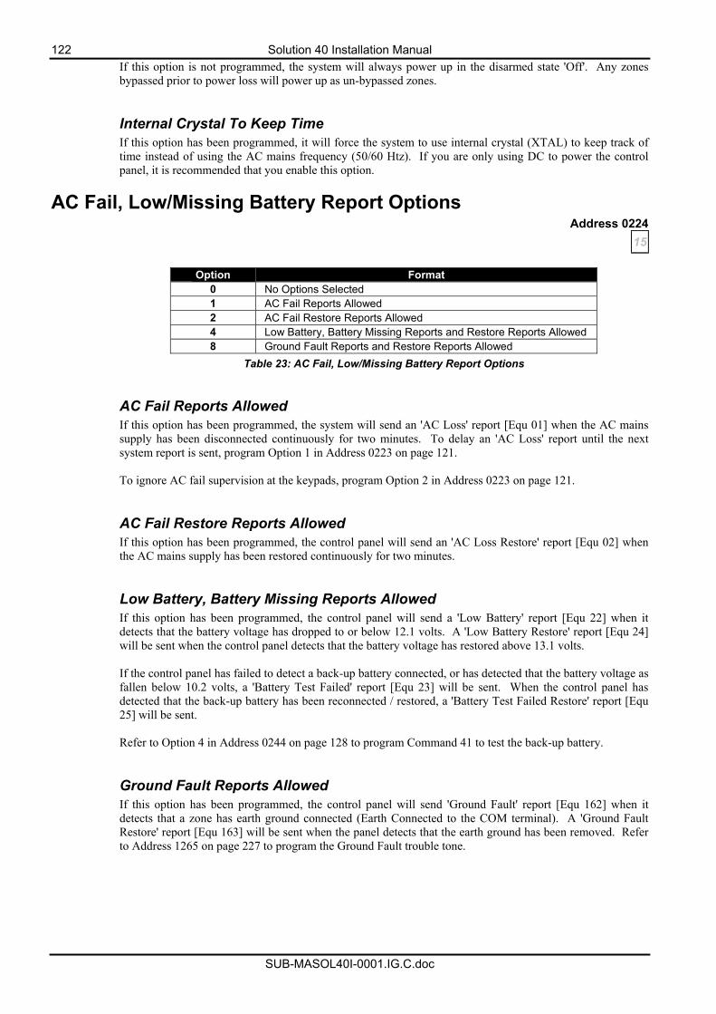
122 Solution 40 Installation Manual
SUB-MASOL40I-0001.IG.C.doc
If this option is not programmed, the system will always power up in the disarmed state 'Off'. Any zones bypassed prior to power loss will power up as un-bypassed zones. Internal Crystal To Keep Time If this option has been programmed, it will force the system to use internal crystal (XTAL) to keep track of time instead of using the AC mains frequency (50/60 Htz). If you are only using DC to power the control panel, it is recommended that you enable this option.
AC Fail, Low/Missing Battery Report Options Address 0224
15
Option Format 0 No Options Selected 1 AC Fail Reports Allowed 2 AC Fail Restore Reports Allowed 4 Low Battery, Battery Missing Reports and Restore Reports Allowed 8 Ground Fault Reports and Restore Reports Allowed
Table 23: AC Fail, Low/Missing Battery Report Options AC Fail Reports Allowed If this option has been programmed, the system will send an 'AC Loss' report [Equ 01] when the AC mains supply has been disconnected continuously for two minutes. To delay an 'AC Loss' report until the next system report is sent, program Option 1 in Address 0223 on page 121. To ignore AC fail supervision at the keypads, program Option 2 in Address 0223 on page 121.
AC Fail Restore Reports Allowed If this option has been programmed, the control panel will send an 'AC Loss Restore' report [Equ 02] when the AC mains supply has been restored continuously for two minutes. Low Battery, Battery Missing Reports Allowed If this option has been programmed, the control panel will send a 'Low Battery' report [Equ 22] when it detects that the battery voltage has dropped to or below 12.1 volts. A 'Low Battery Restore' report [Equ 24] will be sent when the control panel detects that the battery voltage has restored above 13.1 volts. If the control panel has failed to detect a back-up battery connected, or has detected that the battery voltage as fallen below 10.2 volts, a 'Battery Test Failed' report [Equ 23] will be sent. When the control panel has detected that the back-up battery has been reconnected / restored, a 'Battery Test Failed Restore' report [Equ 25] will be sent. Refer to Option 4 in Address 0244 on page 128 to program Command 41 to test the back-up battery. Ground Fault Reports Allowed If this option has been programmed, the control panel will send 'Ground Fault' report [Equ 162] when it detects that a zone has earth ground connected (Earth Connected to the COM terminal). A 'Ground Fault Restore' report [Equ 163] will be sent when the panel detects that the earth ground has been removed. Refer to Address 1265 on page 227 to program the Ground Fault trouble tone.
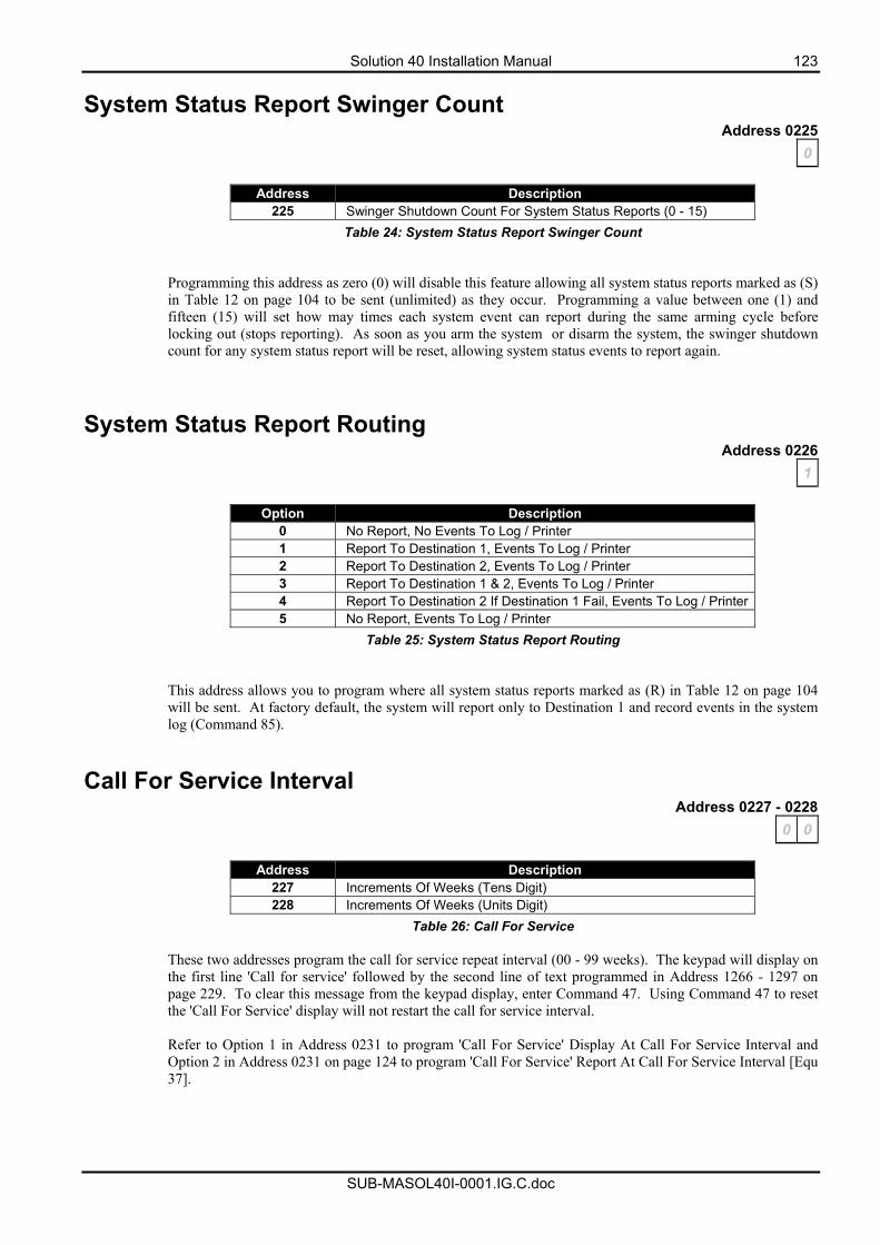
Solution 40 Installation Manual 123
SUB-MASOL40I-0001.IG.C.doc
System Status Report Swinger Count Address 0225
0
Address Description 225 Swinger Shutdown Count For System Status Reports (0 - 15)
Table 24: System Status Report Swinger Count
Programming this address as zero (0) will disable this feature allowing all system status reports marked as (S) in Table 12 on page 104 to be sent (unlimited) as they occur. Programming a value between one (1) and fifteen (15) will set how may times each system event can report during the same arming cycle before locking out (stops reporting). As soon as you arm the system or disarm the system, the swinger shutdown count for any system status report will be reset, allowing system status events to report again.
System Status Report Routing Address 0226
1
Option Description 0 No Report, No Events To Log / Printer 1 Report To Destination 1, Events To Log / Printer 2 Report To Destination 2, Events To Log / Printer 3 Report To Destination 1 & 2, Events To Log / Printer 4 Report To Destination 2 If Destination 1 Fail, Events To Log / Printer5 No Report, Events To Log / Printer
Table 25: System Status Report Routing
This address allows you to program where all system status reports marked as (R) in Table 12 on page 104 will be sent. At factory default, the system will report only to Destination 1 and record events in the system log (Command 85).
Call For Service Interval Address 0227 - 0228
0 0
Address Description 227 Increments Of Weeks (Tens Digit) 228 Increments Of Weeks (Units Digit)
Table 26: Call For Service
These two addresses program the call for service repeat interval (00 - 99 weeks). The keypad will display on the first line 'Call for service' followed by the second line of text programmed in Address 1266 - 1297 on page 229. To clear this message from the keypad display, enter Command 47. Using Command 47 to reset the 'Call For Service' display will not restart the call for service interval. Refer to Option 1 in Address 0231 to program 'Call For Service' Display At Call For Service Interval and Option 2 in Address 0231 on page 124 to program 'Call For Service' Report At Call For Service Interval [Equ 37].
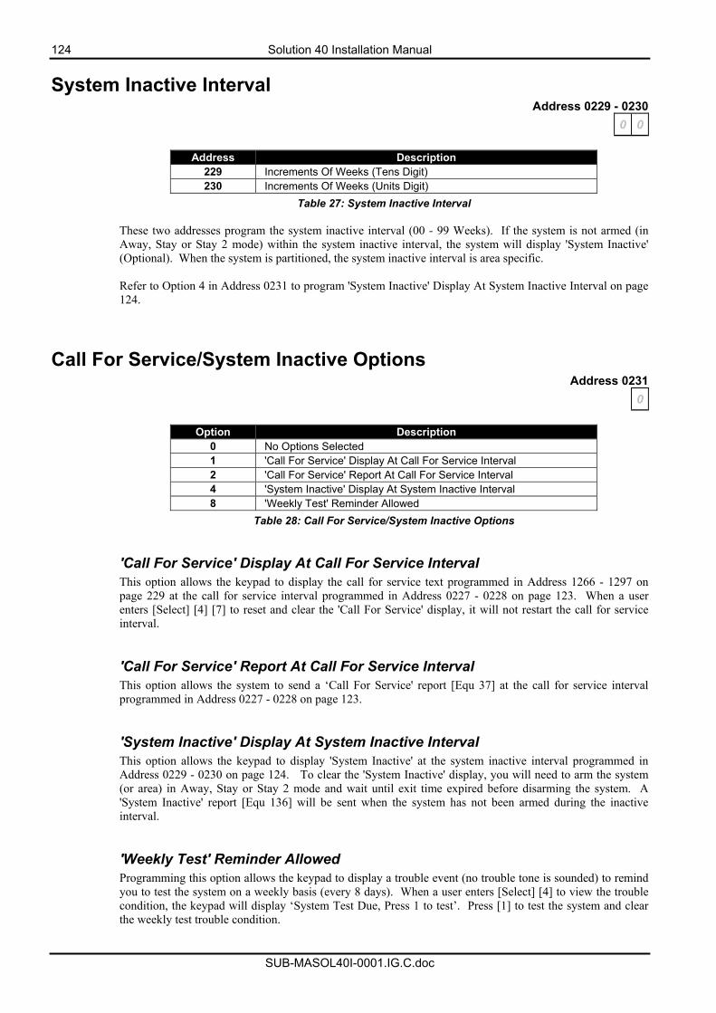
124 Solution 40 Installation Manual
SUB-MASOL40I-0001.IG.C.doc
System Inactive Interval Address 0229 - 0230
0 0
Address Description 229 Increments Of Weeks (Tens Digit) 230 Increments Of Weeks (Units Digit)
Table 27: System Inactive Interval
These two addresses program the system inactive interval (00 - 99 Weeks). If the system is not armed (in Away, Stay or Stay 2 mode) within the system inactive interval, the system will display 'System Inactive' (Optional). When the system is partitioned, the system inactive interval is area specific.
Refer to Option 4 in Address 0231 to program 'System Inactive' Display At System Inactive Interval on page 124.
Call For Service/System Inactive Options Address 0231
0
Option Description 0 No Options Selected 1 'Call For Service' Display At Call For Service Interval 2 'Call For Service' Report At Call For Service Interval 4 'System Inactive' Display At System Inactive Interval 8 'Weekly Test' Reminder Allowed
Table 28: Call For Service/System Inactive Options
'Call For Service' Display At Call For Service Interval This option allows the keypad to display the call for service text programmed in Address 1266 - 1297 on page 229 at the call for service interval programmed in Address 0227 - 0228 on page 123. When a user enters [Select] [4] [7] to reset and clear the 'Call For Service' display, it will not restart the call for service interval.
'Call For Service' Report At Call For Service Interval This option allows the system to send a ‘Call For Service' report [Equ 37] at the call for service interval programmed in Address 0227 - 0228 on page 123.
'System Inactive' Display At System Inactive Interval This option allows the keypad to display 'System Inactive' at the system inactive interval programmed in Address 0229 - 0230 on page 124. To clear the 'System Inactive' display, you will need to arm the system (or area) in Away, Stay or Stay 2 mode and wait until exit time expired before disarming the system. A 'System Inactive' report [Equ 136] will be sent when the system has not been armed during the inactive interval.
'Weekly Test' Reminder Allowed Programming this option allows the keypad to display a trouble event (no trouble tone is sounded) to remind you to test the system on a weekly basis (every 8 days). When a user enters [Select] [4] to view the trouble condition, the keypad will display ‘System Test Due, Press 1 to test’. Press [1] to test the system and clear the weekly test trouble condition.
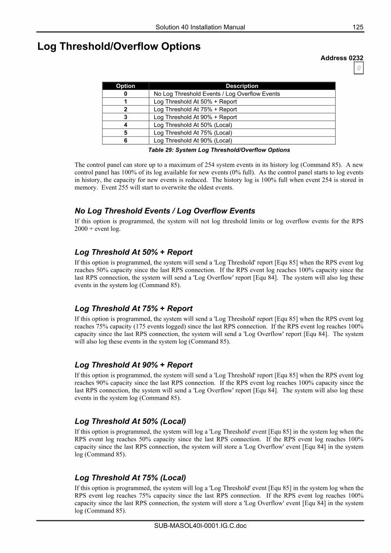
Solution 40 Installation Manual 125
SUB-MASOL40I-0001.IG.C.doc
Log Threshold/Overflow Options Address 0232
0
Option Description 0 No Log Threshold Events / Log Overflow Events 1 Log Threshold At 50% + Report 2 Log Threshold At 75% + Report 3 Log Threshold At 90% + Report 4 Log Threshold At 50% (Local) 5 Log Threshold At 75% (Local) 6 Log Threshold At 90% (Local)
Table 29: System Log Threshold/Overflow Options
The control panel can store up to a maximum of 254 system events in its history log (Command 85). A new control panel has 100% of its log available for new events (0% full). As the control panel starts to log events in history, the capacity for new events is reduced. The history log is 100% full when event 254 is stored in memory. Event 255 will start to overwrite the oldest events.
No Log Threshold Events / Log Overflow Events If this option is programmed, the system will not log threshold limits or log overflow events for the RPS 2000 + event log. Log Threshold At 50% + Report If this option is programmed, the system will send a 'Log Threshold' report [Equ 85] when the RPS event log reaches 50% capacity since the last RPS connection. If the RPS event log reaches 100% capacity since the last RPS connection, the system will send a 'Log Overflow' report [Equ 84]. The system will also log these events in the system log (Command 85). Log Threshold At 75% + Report If this option is programmed, the system will send a 'Log Threshold' report [Equ 85] when the RPS event log reaches 75% capacity (175 events logged) since the last RPS connection. If the RPS event log reaches 100% capacity since the last RPS connection, the system will send a 'Log Overflow' report [Equ 84]. The system will also log these events in the system log (Command 85).
Log Threshold At 90% + Report If this option is programmed, the system will send a 'Log Threshold' report [Equ 85] when the RPS event log reaches 90% capacity since the last RPS connection. If the RPS event log reaches 100% capacity since the last RPS connection, the system will send a 'Log Overflow' report [Equ 84]. The system will also log these events in the system log (Command 85). Log Threshold At 50% (Local) If this option is programmed, the system will log a 'Log Threshold' event [Equ 85] in the system log when the RPS event log reaches 50% capacity since the last RPS connection. If the RPS event log reaches 100% capacity since the last RPS connection, the system will store a 'Log Overflow' event [Equ 84] in the system log (Command 85). Log Threshold At 75% (Local) If this option is programmed, the system will log a 'Log Threshold' event [Equ 85] in the system log when the RPS event log reaches 75% capacity since the last RPS connection. If the RPS event log reaches 100% capacity since the last RPS connection, the system will store a 'Log Overflow' event [Equ 84] in the system log (Command 85).
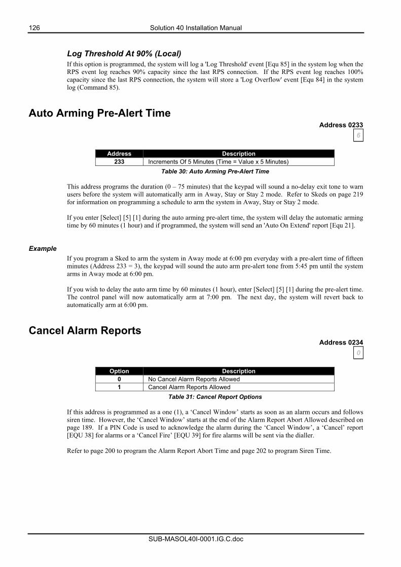
126 Solution 40 Installation Manual
SUB-MASOL40I-0001.IG.C.doc
Log Threshold At 90% (Local) If this option is programmed, the system will log a 'Log Threshold' event [Equ 85] in the system log when the RPS event log reaches 90% capacity since the last RPS connection. If the RPS event log reaches 100% capacity since the last RPS connection, the system will store a 'Log Overflow' event [Equ 84] in the system log (Command 85).
Auto Arming Pre-Alert Time Address 0233
6
Address Description 233 Increments Of 5 Minutes (Time = Value x 5 Minutes)
Table 30: Auto Arming Pre-Alert Time
This address programs the duration (0 – 75 minutes) that the keypad will sound a no-delay exit tone to warn users before the system will automatically arm in Away, Stay or Stay 2 mode. Refer to Skeds on page 219 for information on programming a schedule to arm the system in Away, Stay or Stay 2 mode. If you enter [Select] [5] [1] during the auto arming pre-alert time, the system will delay the automatic arming time by 60 minutes (1 hour) and if programmed, the system will send an 'Auto On Extend' report [Equ 21].
Example
If you program a Sked to arm the system in Away mode at 6:00 pm everyday with a pre-alert time of fifteen minutes (Address 233 = 3), the keypad will sound the auto arm pre-alert tone from 5:45 pm until the system arms in Away mode at 6:00 pm. If you wish to delay the auto arm time by 60 minutes (1 hour), enter [Select] [5] [1] during the pre-alert time. The control panel will now automatically arm at 7:00 pm. The next day, the system will revert back to automatically arm at 6:00 pm.
Cancel Alarm Reports Address 0234
0
Option Description 0 No Cancel Alarm Reports Allowed 1 Cancel Alarm Reports Allowed
Table 31: Cancel Report Options
If this address is programmed as a one (1), a ‘Cancel Window’ starts as soon as an alarm occurs and follows siren time. However, the ‘Cancel Window’ starts at the end of the Alarm Report Abort Allowed described on page 189. If a PIN Code is used to acknowledge the alarm during the ‘Cancel Window’, a ‘Cancel’ report [EQU 38] for alarms or a ‘Cancel Fire’ [EQU 39] for fire alarms will be sent via the dialler. Refer to page 200 to program the Alarm Report Abort Time and page 202 to program Siren Time.
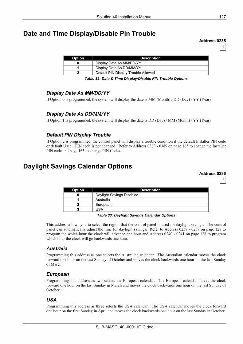
Solution 40 Installation Manual 127
SUB-MASOL40I-0001.IG.C.doc
Date and Time Display/Disable Pin Trouble Address 0235
3
Option Description 0 Display Date As MM/DD/YY 1 Display Date As DD/MM/YY 2 Default PIN Display Trouble Allowed
Table 32: Date & Time Display/Disable PIN Trouble Options
Display Date As MM/DD/YY If Option 0 is programmed, the system will display the date is MM (Month) / DD (Day) / YY (Year). Display Date As DD/MM/YY If Option 1 is programmed, the system will display the date is DD (Day) / MM (Month) / YY (Year). Default PIN Display Trouble If Option 2 is programmed, the control panel will display a trouble condition if the default Installer PIN code or default User 1 PIN code is not changed. Refer to Address 0383 - 0389 on page 165 to change the Installer PIN code and page 165 to change PIN Codes.
Daylight Savings Calendar Options Address 0236
1
Option Description 0 Daylight Savings Disabled 1 Australia 2 European 3 USA
Table 33: Daylight Savings Calendar Options This address allows you to select the region that the control panel is used for daylight savings. The control panel can automatically adjust the time for daylight savings. Refer to Address 0238 - 0239 on page 128 to program the which hour the clock will advance one hour and Address 0240 - 0241 on page 128 to program which hour the clock will go backwards one hour. Australia Programming this address as one selects the Australian calendar. The Australian calendar moves the clock forward one hour on the last Sunday of October and moves the clock backwards one hour on the last Sunday of March. European Programming this address as two selects the European calendar. The European calendar moves the clock forward one hour on the last Sunday in March and moves the clock backwards one hour on the last Sunday of October. USA Programming this address as three selects the USA calendar. The USA calendar moves the clock forward one hour on the first Sunday in April and moves the clock backwards one hour on the last Sunday in October.
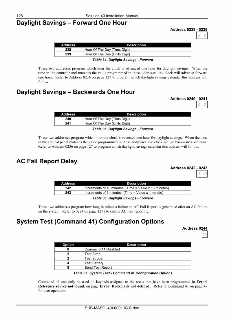
128 Solution 40 Installation Manual
SUB-MASOL40I-0001.IG.C.doc
Daylight Savings – Forward One Hour Address 0238 - 0239
0 2
Address Description 238 Hour Of The Day (Tens Digit) 239 Hour Of The Day (Units Digit)
Table 34: Daylight Savings - Forward These two addresses program which hour the clock is advanced one hour for daylight savings. When the time in the control panel matches the value programmed in these addresses, the clock will advance forward one hour. Refer to Address 0236 on page 127 to program which daylight savings calendar this address will follow.
Daylight Savings – Backwards One Hour Address 0240 - 0241
0 3
Address Description 240 Hour Of The Day (Tens Digit) 241 Hour Of The Day (Units Digit)
Table 35: Daylight Savings - Forward These two addresses program which hour the clock is reversed one hour for daylight savings. When the time in the control panel matches the value programmed in these addresses, the clock will go backwards one hour. Refer to Address 0236 on page 127 to program which daylight savings calendar this address will follow.
AC Fail Report Delay Address 0242 - 0243
3 12
Address Description 242 Increments of 16 minutes ( Time = Value x 16 minutes) 243 Increments of 1 minutes (Time = Value x 1 minute)
Table 36: Daylight Savings - Forward These two addresses program how long in minutes before an AC Fail Report is generated after an AC failure on the system. Refer to 0224 on page 1271 to enable AC Fail reporting.
System Test (Command 41) Configuration Options Address 0244
15
Option Description 0 Command 41 Disabled 1 Test Siren 2 Test Strobe 4 Test Battery 8 Send Test Report
Table 37: System Test - Command 41 Configuration Options Command 41 can only be used on keypads assigned to the areas that have been programmed in Error! Reference source not found. on page Error! Bookmark not defined.. Refer to Command 41 on page 47 for user operation.
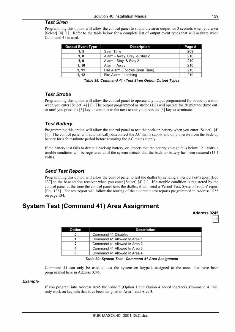
Solution 40 Installation Manual 129
SUB-MASOL40I-0001.IG.C.doc
Test Siren Programming this option will allow the control panel to sound the siren output for 3 seconds when you enter [Select] [4] [1]. Refer to the table below for a complete list of output event types that will activate when Command 41 is used.
Output Event Type Description Page #
1, 5 Siren Time 209 1, 8 Alarm - Away, Stay & Stay 2 210 1, 9 Alarm - Stay & Stay 2 210
1, 10 Alarm - Away 210 1, 11 Fire Alarm (Follows Siren Time) 210 1, 12 Fire Alarm - Latching 210
Table 38: Command 41 - Test Siren Option Output Types
Test Strobe Programming this option will allow the control panel to operate any output programmed for strobe operation when you enter [Select] 4] [1]. The output programmed as strobe (1,6) will operate for 20 minutes (time out) or until you press the [*] key to continue to the next test or you press the [#] key to terminate. Test Battery Programming this option will allow the control panel to test the back-up battery when you enter [Select] [4] [1]. The control panel will automatically disconnect the AC mains supply and only operate from the back-up battery for a four-minute period before restoring the AC mains supply. If the battery test fails to detect a back-up battery, or, detects that the battery voltage falls below 12.1 volts, a trouble condition will be registered until the system detects that the back-up battery has been restored (13.1 volts). Send Test Report Programming this option will allow the control panel to test the dialler by sending a 'Period Test' report [Equ 137] to the base station receiver when you enter [Select] [4] [1]. If a trouble condition is registered by the control panel at the time the control panel tests the dialler, it will send a 'Period Test, System Trouble' report [Equ 138]. The test report will follow the routing of the automatic test reports programmed in Address 0255 on page 134.
System Test (Command 41) Area Assignment Address 0245
15
Option Description 0 Command 41 Disabled 1 Command 41 Allowed In Area 1 2 Command 41 Allowed In Area 2 4 Command 41 Allowed In Area 3 8 Command 41 Allowed In Area 4
Table 39: System Test - Command 41 Area Assignment
Command 41 can only be used to test the system on keypads assigned to the areas that have been programmed here in Address 0245.
Example
If you program into Address 0245 the value 5 (Option 1 and Option 4 added together), Command 41 will only work on keypads that have been assigned to Area 1 and Area 3.
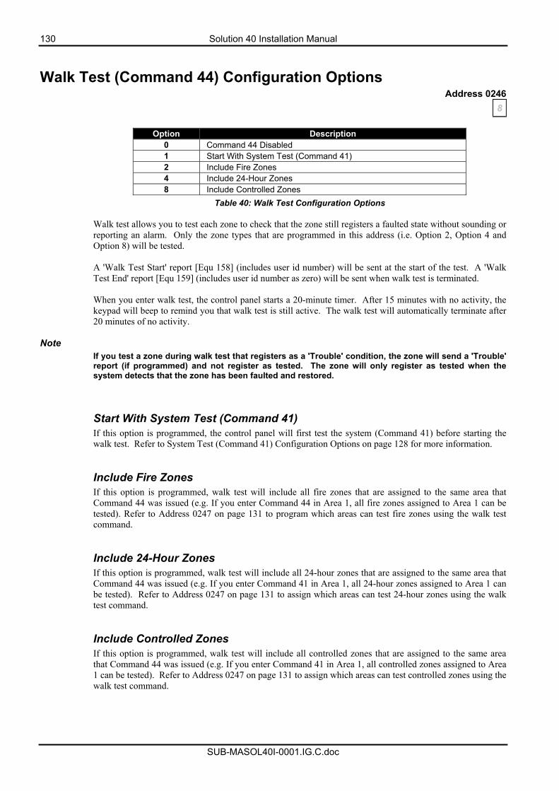
130 Solution 40 Installation Manual
SUB-MASOL40I-0001.IG.C.doc
Walk Test (Command 44) Configuration Options Address 0246
8
Option Description 0 Command 44 Disabled 1 Start With System Test (Command 41) 2 Include Fire Zones 4 Include 24-Hour Zones 8 Include Controlled Zones
Table 40: Walk Test Configuration Options
Walk test allows you to test each zone to check that the zone still registers a faulted state without sounding or reporting an alarm. Only the zone types that are programmed in this address (i.e. Option 2, Option 4 and Option 8) will be tested. A 'Walk Test Start' report [Equ 158] (includes user id number) will be sent at the start of the test. A 'Walk Test End' report [Equ 159] (includes user id number as zero) will be sent when walk test is terminated. When you enter walk test, the control panel starts a 20-minute timer. After 15 minutes with no activity, the keypad will beep to remind you that walk test is still active. The walk test will automatically terminate after 20 minutes of no activity.
Note If you test a zone during walk test that registers as a 'Trouble' condition, the zone will send a 'Trouble' report (if programmed) and not register as tested. The zone will only register as tested when the system detects that the zone has been faulted and restored.
Start With System Test (Command 41) If this option is programmed, the control panel will first test the system (Command 41) before starting the walk test. Refer to System Test (Command 41) Configuration Options on page 128 for more information.
Include Fire Zones If this option is programmed, walk test will include all fire zones that are assigned to the same area that Command 44 was issued (e.g. If you enter Command 44 in Area 1, all fire zones assigned to Area 1 can be tested). Refer to Address 0247 on page 131 to program which areas can test fire zones using the walk test command.
Include 24-Hour Zones If this option is programmed, walk test will include all 24-hour zones that are assigned to the same area that Command 44 was issued (e.g. If you enter Command 41 in Area 1, all 24-hour zones assigned to Area 1 can be tested). Refer to Address 0247 on page 131 to assign which areas can test 24-hour zones using the walk test command.
Include Controlled Zones If this option is programmed, walk test will include all controlled zones that are assigned to the same area that Command 44 was issued (e.g. If you enter Command 41 in Area 1, all controlled zones assigned to Area 1 can be tested). Refer to Address 0247 on page 131 to assign which areas can test controlled zones using the walk test command.
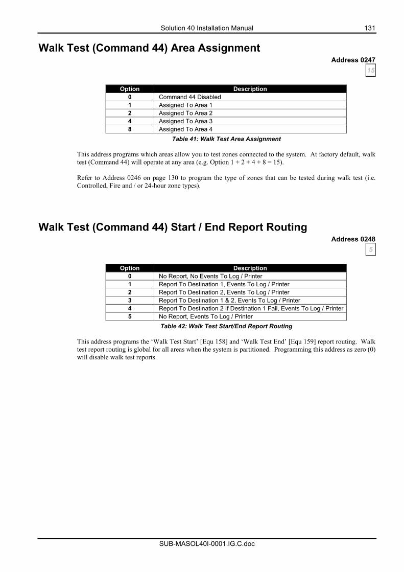
Solution 40 Installation Manual 131
SUB-MASOL40I-0001.IG.C.doc
Walk Test (Command 44) Area Assignment Address 0247
15
Option Description 0 Command 44 Disabled 1 Assigned To Area 1 2 Assigned To Area 2 4 Assigned To Area 3 8 Assigned To Area 4
Table 41: Walk Test Area Assignment
This address programs which areas allow you to test zones connected to the system. At factory default, walk test (Command 44) will operate at any area (e.g. Option 1 + 2 + 4 + 8 = 15). Refer to Address 0246 on page 130 to program the type of zones that can be tested during walk test (i.e. Controlled, Fire and / or 24-hour zone types).
Walk Test (Command 44) Start / End Report Routing Address 0248
5
Option Description 0 No Report, No Events To Log / Printer 1 Report To Destination 1, Events To Log / Printer 2 Report To Destination 2, Events To Log / Printer 3 Report To Destination 1 & 2, Events To Log / Printer 4 Report To Destination 2 If Destination 1 Fail, Events To Log / Printer5 No Report, Events To Log / Printer
Table 42: Walk Test Start/End Report Routing
This address programs the ‘Walk Test Start’ [Equ 158] and ‘Walk Test End’ [Equ 159] report routing. Walk test report routing is global for all areas when the system is partitioned. Programming this address as zero (0) will disable walk test reports.
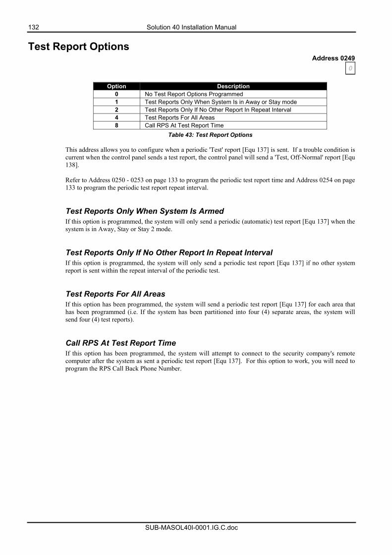
132 Solution 40 Installation Manual
SUB-MASOL40I-0001.IG.C.doc
Test Report Options Address 0249
0
Option Description 0 No Test Report Options Programmed 1 Test Reports Only When System Is in Away or Stay mode 2 Test Reports Only If No Other Report In Repeat Interval 4 Test Reports For All Areas 8 Call RPS At Test Report Time
Table 43: Test Report Options This address allows you to configure when a periodic 'Test' report [Equ 137] is sent. If a trouble condition is current when the control panel sends a test report, the control panel will send a 'Test, Off-Normal' report [Equ 138]. Refer to Address 0250 - 0253 on page 133 to program the periodic test report time and Address 0254 on page 133 to program the periodic test report repeat interval.
Test Reports Only When System Is Armed If this option is programmed, the system will only send a periodic (automatic) test report [Equ 137] when the system is in Away, Stay or Stay 2 mode. Test Reports Only If No Other Report In Repeat Interval If this option is programmed, the system will only send a periodic test report [Equ 137] if no other system report is sent within the repeat interval of the periodic test. Test Reports For All Areas If this option has been programmed, the system will send a periodic test report [Equ 137] for each area that has been programmed (i.e. If the system has been partitioned into four (4) separate areas, the system will send four (4) test reports). Call RPS At Test Report Time If this option has been programmed, the system will attempt to connect to the security company's remote computer after the system as sent a periodic test report [Equ 137]. For this option to work, you will need to program the RPS Call Back Phone Number.
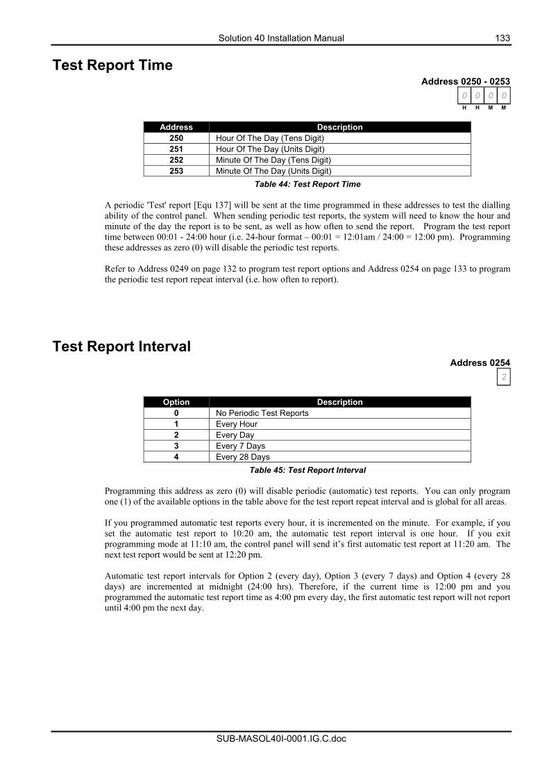
Solution 40 Installation Manual 133
SUB-MASOL40I-0001.IG.C.doc
Test Report Time Address 0250 - 0253
0 0 0 0H H M M
Address Description
250 Hour Of The Day (Tens Digit) 251 Hour Of The Day (Units Digit) 252 Minute Of The Day (Tens Digit) 253 Minute Of The Day (Units Digit)
Table 44: Test Report Time
A periodic 'Test' report [Equ 137] will be sent at the time programmed in these addresses to test the dialling ability of the control panel. When sending periodic test reports, the system will need to know the hour and minute of the day the report is to be sent, as well as how often to send the report. Program the test report time between 00:01 - 24:00 hour (i.e. 24-hour format – 00:01 = 12:01am / 24:00 = 12:00 pm). Programming these addresses as zero (0) will disable the periodic test reports. Refer to Address 0249 on page 132 to program test report options and Address 0254 on page 133 to program the periodic test report repeat interval (i.e. how often to report).
Test Report Interval Address 0254
2
Option Description 0 No Periodic Test Reports 1 Every Hour 2 Every Day 3 Every 7 Days 4 Every 28 Days
Table 45: Test Report Interval
Programming this address as zero (0) will disable periodic (automatic) test reports. You can only program one (1) of the available options in the table above for the test report repeat interval and is global for all areas. If you programmed automatic test reports every hour, it is incremented on the minute. For example, if you set the automatic test report to 10:20 am, the automatic test report interval is one hour. If you exit programming mode at 11:10 am, the control panel will send it’s first automatic test report at 11:20 am. The next test report would be sent at 12:20 pm. Automatic test report intervals for Option 2 (every day), Option 3 (every 7 days) and Option 4 (every 28 days) are incremented at midnight (24:00 hrs). Therefore, if the current time is 12:00 pm and you programmed the automatic test report time as 4:00 pm every day, the first automatic test report will not report until 4:00 pm the next day.
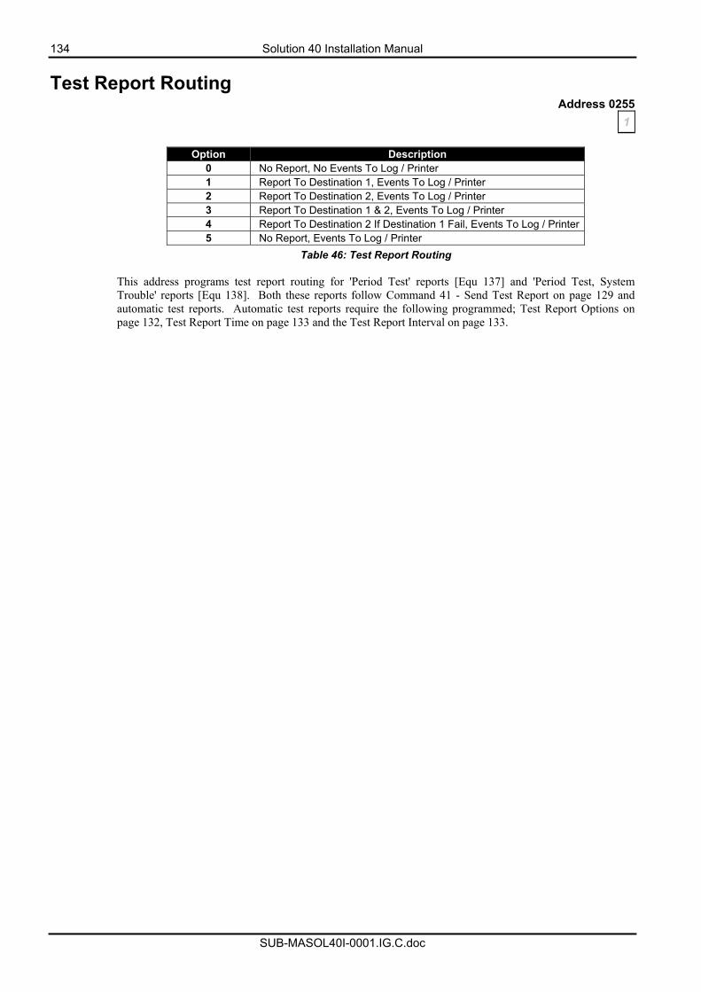
134 Solution 40 Installation Manual
SUB-MASOL40I-0001.IG.C.doc
Test Report Routing Address 0255
1
Option Description 0 No Report, No Events To Log / Printer 1 Report To Destination 1, Events To Log / Printer 2 Report To Destination 2, Events To Log / Printer 3 Report To Destination 1 & 2, Events To Log / Printer 4 Report To Destination 2 If Destination 1 Fail, Events To Log / Printer 5 No Report, Events To Log / Printer
Table 46: Test Report Routing
This address programs test report routing for 'Period Test' reports [Equ 137] and 'Period Test, System Trouble' reports [Equ 138]. Both these reports follow Command 41 - Send Test Report on page 129 and automatic test reports. Automatic test reports require the following programmed; Test Report Options on page 132, Test Report Time on page 133 and the Test Report Interval on page 133.
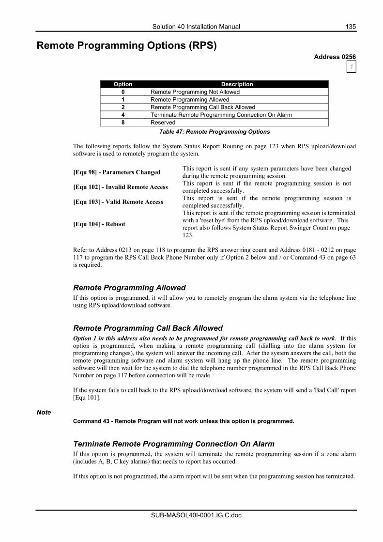
Solution 40 Installation Manual 135
SUB-MASOL40I-0001.IG.C.doc
Remote Programming Options (RPS) Address 0256
1
Option Description 0 Remote Programming Not Allowed 1 Remote Programming Allowed 2 Remote Programming Call Back Allowed 4 Terminate Remote Programming Connection On Alarm 8 Reserved
Table 47: Remote Programming Options The following reports follow the System Status Report Routing on page 123 when RPS upload/download software is used to remotely program the system.
[Equ 98] - Parameters Changed This report is sent if any system parameters have been changed during the remote programming session.
[Equ 102] - Invalid Remote Access This report is sent if the remote programming session is not completed successfully.
[Equ 103] - Valid Remote Access This report is sent if the remote programming session is completed successfully.
[Equ 104] - Reboot
This report is sent if the remote programming session is terminated with a 'reset bye' from the RPS upload/download software. This report also follows System Status Report Swinger Count on page 123.
Refer to Address 0213 on page 118 to program the RPS answer ring count and Address 0181 - 0212 on page 117 to program the RPS Call Back Phone Number only if Option 2 below and / or Command 43 on page 63 is required.
Remote Programming Allowed If this option is programmed, it will allow you to remotely program the alarm system via the telephone line using RPS upload/download software.
Remote Programming Call Back Allowed Option 1 in this address also needs to be programmed for remote programming call back to work. If this option is programmed, when making a remote programming call (dialling into the alarm system for programming changes), the system will answer the incoming call. After the system answers the call, both the remote programming software and alarm system will hang up the phone line. The remote programming software will then wait for the system to dial the telephone number programmed in the RPS Call Back Phone Number on page 117 before connection will be made. If the system fails to call back to the RPS upload/download software, the system will send a 'Bad Call' report [Equ 101].
Note Command 43 - Remote Program will not work unless this option is programmed.
Terminate Remote Programming Connection On Alarm If this option is programmed, the system will terminate the remote programming session if a zone alarm (includes A, B, C key alarms) that needs to report has occurred. If this option is not programmed, the alarm report will be sent when the programming session has terminated.

136 Solution 40 Installation Manual
SUB-MASOL40I-0001.IG.C.doc
Programming/Daylight Savings Options Address 0257
12
Option Description 0 No Options Selected 1 Reserved 2 Auto Adjust For DST (Daylight Savings) 4 Keypad Programming Allowed 8 PK32 (Programming Key) Allowed
Table 48: Programming/Daylight Savings Options Auto Adjust For DST (Daylight Savings) Programming this option will allow the control panel to automatically adjust the time for daylight savings (Australia). DST will commence at 2 am on the last Sunday in October each year (Clocks should be turned forward one hour to read 3 am) and will end at 2 am on the last Sunday in March (Clocks should be turned back one hour to read 2 am). Keypad Programming Allowed If this option is programmed, the programming parameters of the control panel can be changed via the keypad (or Installer’s keypad). You can only program the control panel via the keypad if the installer switch is shorted (closed). Refer to Programming Via A ‘Text’ Keypad on page 79 for additional information. If this option is not programmed, you can only program the control panel via RPS upload/download software or PK32 programming key (if programmed).
Note If the installer switch is still shorted, the short will disable the following: • All system reporting, including alarms.
• A, B, C key functions.
• Alarm Outputs.
• Activate the 'Call for service' trouble display at all keypads. PK32 (Programming Key) Allowed If this option is programmed, you can transfer programming information between the control panel and the PK32 programming key. If this option is not programmed, transferring information will not be allowed between the control panel and the key. For additional information on using a Program Key, refer to page 90.
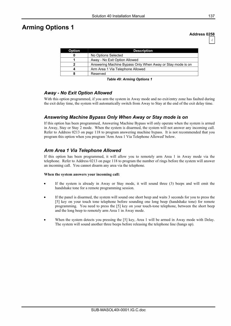
Solution 40 Installation Manual 137
SUB-MASOL40I-0001.IG.C.doc
Arming Options 1 Address 0258
4
Option Description 0 No Options Selected 1 Away - No Exit Option Allowed 2 Answering Machine Bypass Only When Away or Stay mode is on 4 Arm Area 1 Via Telephone Allowed 8 Reserved
Table 49: Arming Options 1 Away - No Exit Option Allowed With this option programmed, if you arm the system in Away mode and no exit/entry zone has faulted during the exit delay time, the system will automatically switch from Away to Stay at the end of the exit delay time. Answering Machine Bypass Only When Away or Stay mode is on If this option has been programmed, Answering Machine Bypass will only operate when the system is armed in Away, Stay or Stay 2 mode. When the system is disarmed, the system will not answer any incoming call. Refer to Address 0213 on page 118 to program answering machine bypass. It is not recommended that you program this option when you program 'Arm Area 1 Via Telephone Allowed' below. Arm Area 1 Via Telephone Allowed If this option has been programmed, it will allow you to remotely arm Area 1 in Away mode via the telephone. Refer to Address 0213 on page 118 to program the number of rings before the system will answer an incoming call. You cannot disarm any area via the telephone.
When the system answers your incoming call: • If the system is already in Away or Stay mode, it will sound three (3) beeps and will emit the
handshake tone for a remote programming session.
• If the panel is disarmed, the system will sound one short beep and waits 3 seconds for you to press the [5] key on your touch tone telephone before sounding one long beep (handshake tone) for remote programming. You need to press the [5] key on your touch-tone telephone, between the short beep and the long beep to remotely arm Area 1 in Away mode.
• When the system detects you pressing the [5] key, Area 1 will be armed in Away mode with Delay.
The system will sound another three beeps before releasing the telephone line (hangs up).
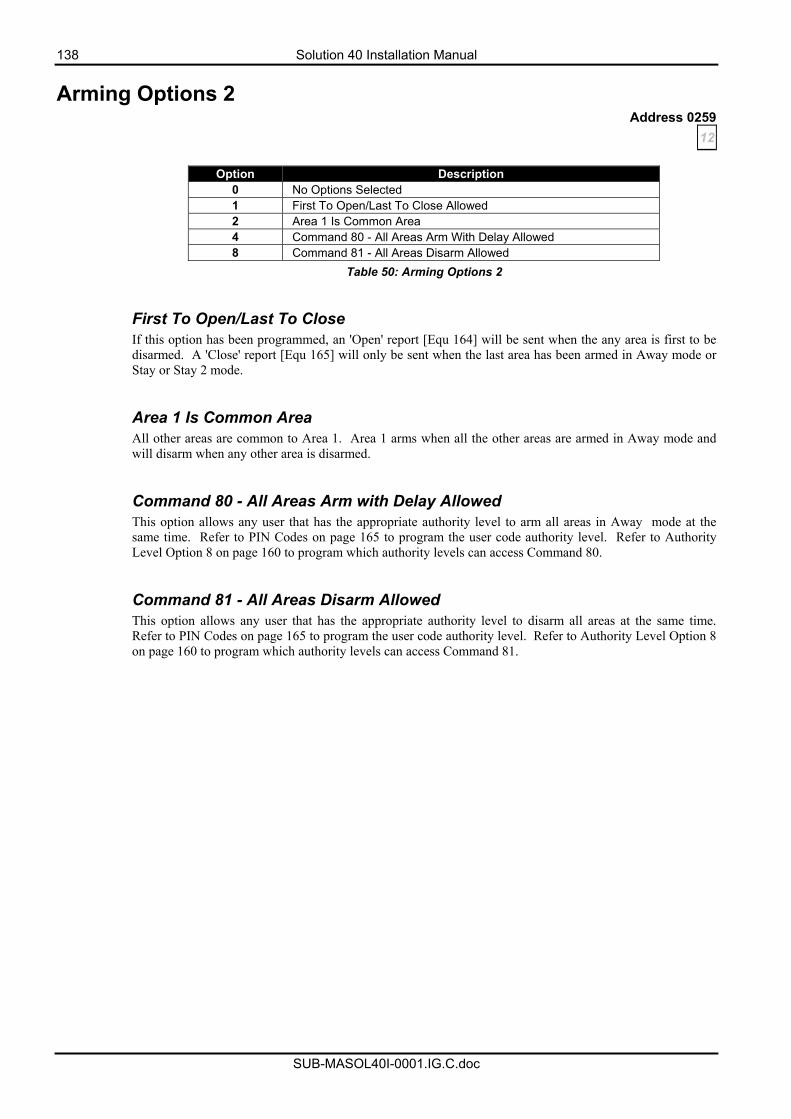
138 Solution 40 Installation Manual
SUB-MASOL40I-0001.IG.C.doc
Arming Options 2 Address 0259
12
Option Description 0 No Options Selected 1 First To Open/Last To Close Allowed 2 Area 1 Is Common Area 4 Command 80 - All Areas Arm With Delay Allowed 8 Command 81 - All Areas Disarm Allowed
Table 50: Arming Options 2 First To Open/Last To Close If this option has been programmed, an 'Open' report [Equ 164] will be sent when the any area is first to be disarmed. A 'Close' report [Equ 165] will only be sent when the last area has been armed in Away mode or Stay or Stay 2 mode. Area 1 Is Common Area All other areas are common to Area 1. Area 1 arms when all the other areas are armed in Away mode and will disarm when any other area is disarmed. Command 80 - All Areas Arm with Delay Allowed This option allows any user that has the appropriate authority level to arm all areas in Away mode at the same time. Refer to PIN Codes on page 165 to program the user code authority level. Refer to Authority Level Option 8 on page 160 to program which authority levels can access Command 80. Command 81 - All Areas Disarm Allowed This option allows any user that has the appropriate authority level to disarm all areas at the same time. Refer to PIN Codes on page 165 to program the user code authority level. Refer to Authority Level Option 8 on page 160 to program which authority levels can access Command 81.
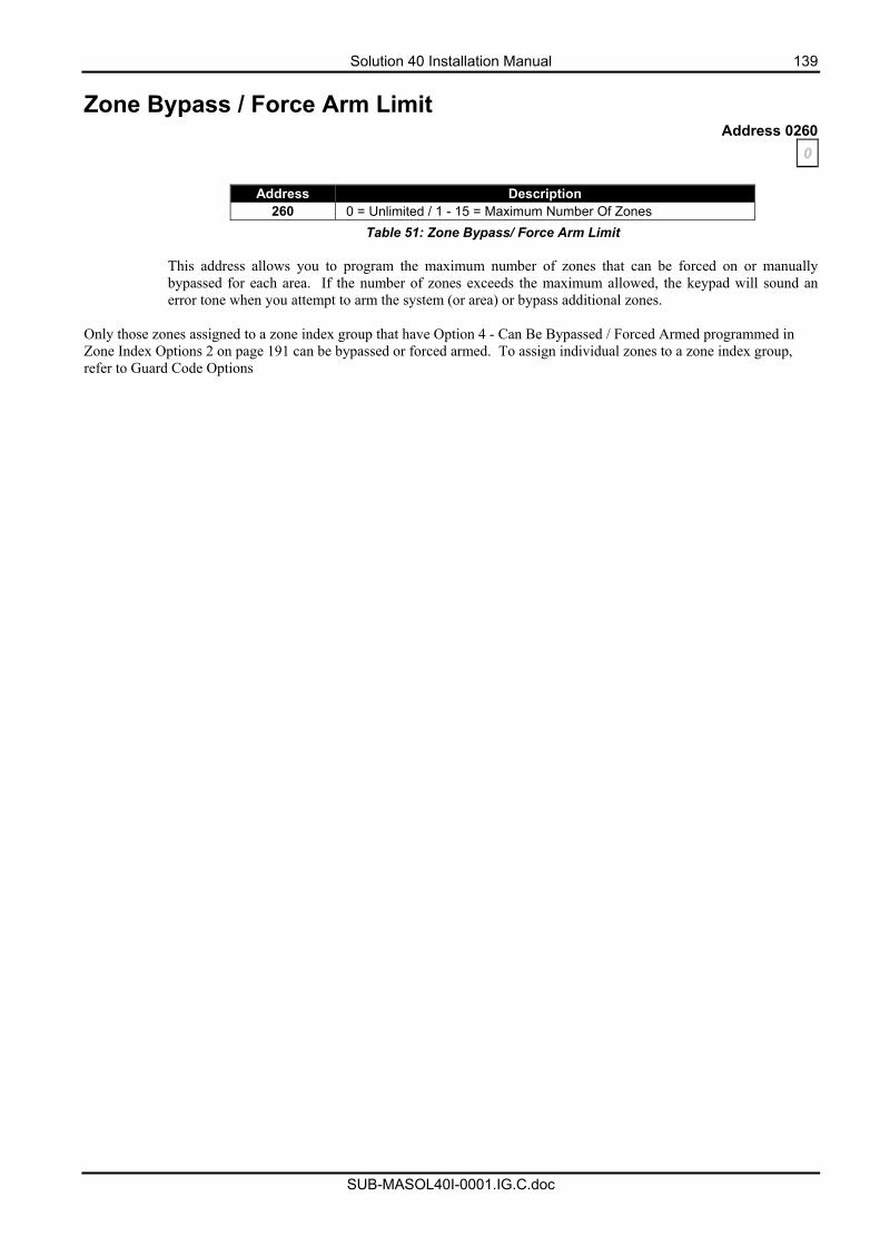
Solution 40 Installation Manual 139
SUB-MASOL40I-0001.IG.C.doc
Zone Bypass / Force Arm Limit Address 0260
0
Address Description 260 0 = Unlimited / 1 - 15 = Maximum Number Of Zones
Table 51: Zone Bypass/ Force Arm Limit This address allows you to program the maximum number of zones that can be forced on or manually bypassed for each area. If the number of zones exceeds the maximum allowed, the keypad will sound an error tone when you attempt to arm the system (or area) or bypass additional zones.
Only those zones assigned to a zone index group that have Option 4 - Can Be Bypassed / Forced Armed programmed in Zone Index Options 2 on page 191 can be bypassed or forced armed. To assign individual zones to a zone index group, refer to Guard Code Options
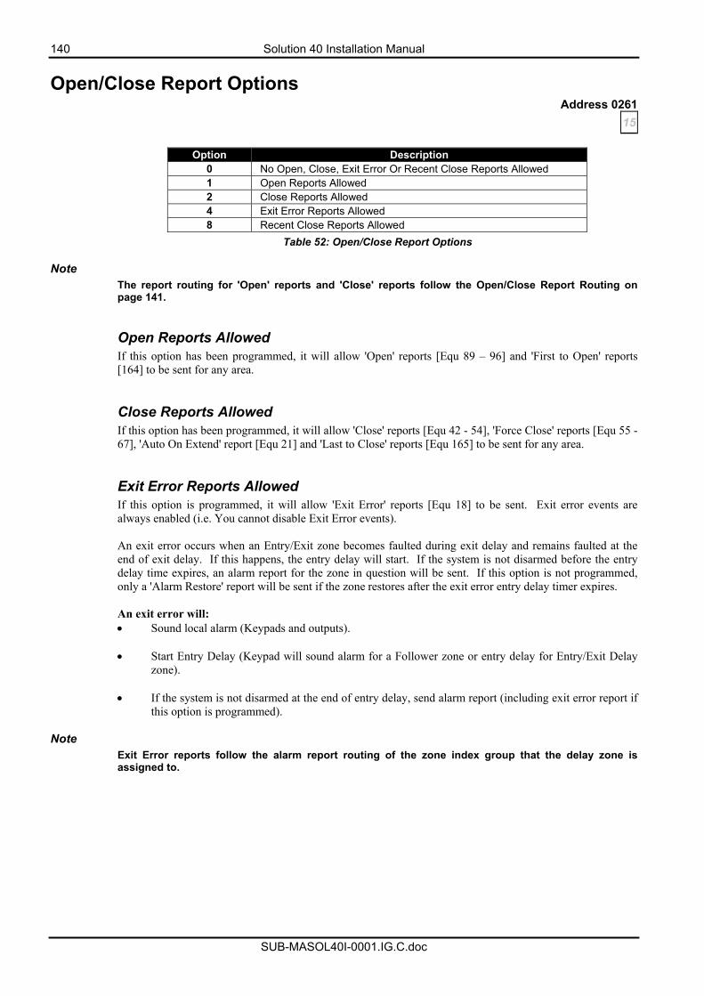
140 Solution 40 Installation Manual
SUB-MASOL40I-0001.IG.C.doc
Open/Close Report Options Address 0261
15
Option Description 0 No Open, Close, Exit Error Or Recent Close Reports Allowed 1 Open Reports Allowed 2 Close Reports Allowed 4 Exit Error Reports Allowed 8 Recent Close Reports Allowed
Table 52: Open/Close Report Options
Note The report routing for 'Open' reports and 'Close' reports follow the Open/Close Report Routing on page 141. Open Reports Allowed If this option has been programmed, it will allow 'Open' reports [Equ 89 – 96] and 'First to Open' reports [164] to be sent for any area. Close Reports Allowed If this option has been programmed, it will allow 'Close' reports [Equ 42 - 54], 'Force Close' reports [Equ 55 - 67], 'Auto On Extend' report [Equ 21] and 'Last to Close' reports [Equ 165] to be sent for any area. Exit Error Reports Allowed If this option is programmed, it will allow 'Exit Error' reports [Equ 18] to be sent. Exit error events are always enabled (i.e. You cannot disable Exit Error events). An exit error occurs when an Entry/Exit zone becomes faulted during exit delay and remains faulted at the end of exit delay. If this happens, the entry delay will start. If the system is not disarmed before the entry delay time expires, an alarm report for the zone in question will be sent. If this option is not programmed, only a 'Alarm Restore' report will be sent if the zone restores after the exit error entry delay timer expires. An exit error will: • Sound local alarm (Keypads and outputs).
• Start Entry Delay (Keypad will sound alarm for a Follower zone or entry delay for Entry/Exit Delay
zone).
• If the system is not disarmed at the end of entry delay, send alarm report (including exit error report if this option is programmed).
Note
Exit Error reports follow the alarm report routing of the zone index group that the delay zone is assigned to.
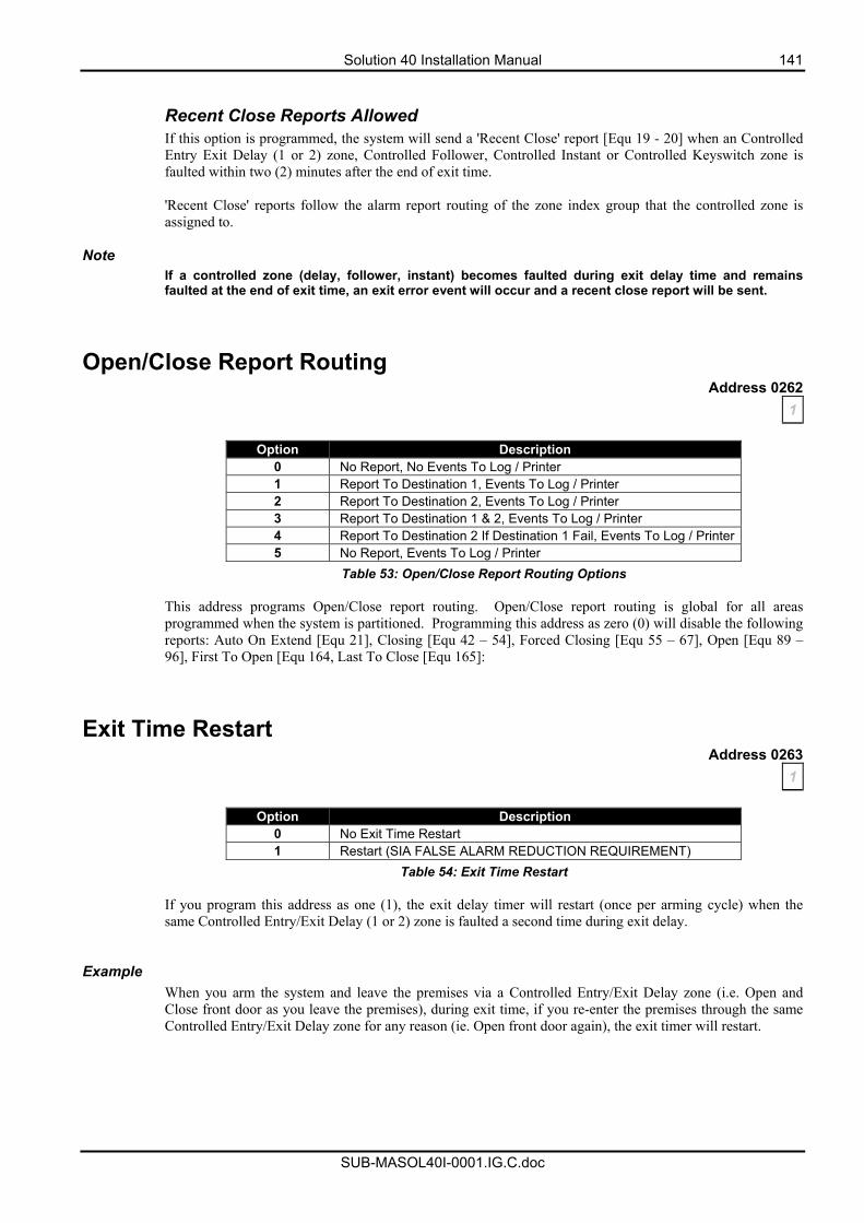
Solution 40 Installation Manual 141
SUB-MASOL40I-0001.IG.C.doc
Recent Close Reports Allowed If this option is programmed, the system will send a 'Recent Close' report [Equ 19 - 20] when an Controlled Entry Exit Delay (1 or 2) zone, Controlled Follower, Controlled Instant or Controlled Keyswitch zone is faulted within two (2) minutes after the end of exit time. 'Recent Close' reports follow the alarm report routing of the zone index group that the controlled zone is assigned to.
Note If a controlled zone (delay, follower, instant) becomes faulted during exit delay time and remains faulted at the end of exit time, an exit error event will occur and a recent close report will be sent.
Open/Close Report Routing Address 0262
1
Option Description 0 No Report, No Events To Log / Printer 1 Report To Destination 1, Events To Log / Printer 2 Report To Destination 2, Events To Log / Printer 3 Report To Destination 1 & 2, Events To Log / Printer 4 Report To Destination 2 If Destination 1 Fail, Events To Log / Printer5 No Report, Events To Log / Printer
Table 53: Open/Close Report Routing Options
This address programs Open/Close report routing. Open/Close report routing is global for all areas programmed when the system is partitioned. Programming this address as zero (0) will disable the following reports: Auto On Extend [Equ 21], Closing [Equ 42 – 54], Forced Closing [Equ 55 – 67], Open [Equ 89 – 96], First To Open [Equ 164, Last To Close [Equ 165]:
Exit Time Restart Address 0263
1
Option Description 0 No Exit Time Restart 1 Restart (SIA FALSE ALARM REDUCTION REQUIREMENT)
Table 54: Exit Time Restart If you program this address as one (1), the exit delay timer will restart (once per arming cycle) when the same Controlled Entry/Exit Delay (1 or 2) zone is faulted a second time during exit delay.
Example
When you arm the system and leave the premises via a Controlled Entry/Exit Delay zone (i.e. Open and Close front door as you leave the premises), during exit time, if you re-enter the premises through the same Controlled Entry/Exit Delay zone for any reason (ie. Open front door again), the exit timer will restart.
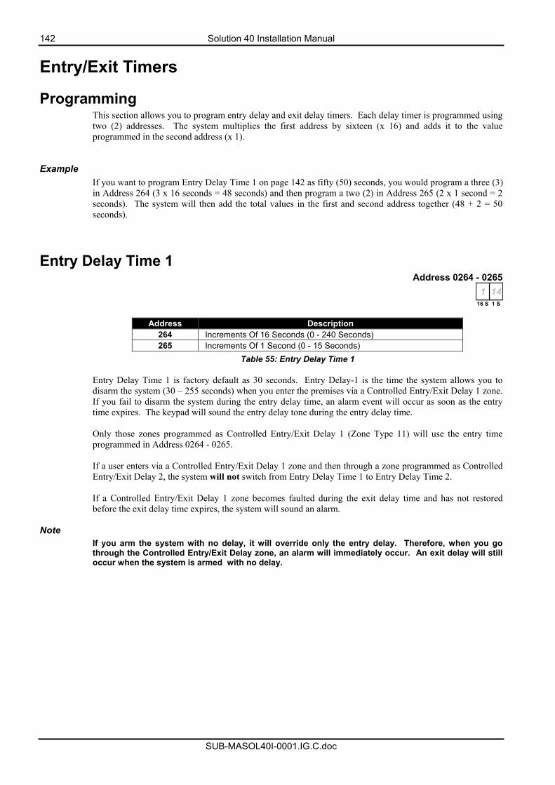
142 Solution 40 Installation Manual
SUB-MASOL40I-0001.IG.C.doc
Entry/Exit Timers
Programming This section allows you to program entry delay and exit delay timers. Each delay timer is programmed using two (2) addresses. The system multiplies the first address by sixteen (x 16) and adds it to the value programmed in the second address (x 1).
Example
If you want to program Entry Delay Time 1 on page 142 as fifty (50) seconds, you would program a three (3) in Address 264 (3 x 16 seconds = 48 seconds) and then program a two (2) in Address 265 (2 x 1 second = 2 seconds). The system will then add the total values in the first and second address together (48 + 2 = 50 seconds).
Entry Delay Time 1 Address 0264 - 0265
1 1416 S 1 S
Address Description
264 Increments Of 16 Seconds (0 - 240 Seconds) 265 Increments Of 1 Second (0 - 15 Seconds)
Table 55: Entry Delay Time 1
Entry Delay Time 1 is factory default as 30 seconds. Entry Delay-1 is the time the system allows you to disarm the system (30 – 255 seconds) when you enter the premises via a Controlled Entry/Exit Delay 1 zone. If you fail to disarm the system during the entry delay time, an alarm event will occur as soon as the entry time expires. The keypad will sound the entry delay tone during the entry delay time. Only those zones programmed as Controlled Entry/Exit Delay 1 (Zone Type 11) will use the entry time programmed in Address 0264 - 0265. If a user enters via a Controlled Entry/Exit Delay 1 zone and then through a zone programmed as Controlled Entry/Exit Delay 2, the system will not switch from Entry Delay Time 1 to Entry Delay Time 2. If a Controlled Entry/Exit Delay 1 zone becomes faulted during the exit delay time and has not restored before the exit delay time expires, the system will sound an alarm.
Note If you arm the system with no delay, it will override only the entry delay. Therefore, when you go through the Controlled Entry/Exit Delay zone, an alarm will immediately occur. An exit delay will still occur when the system is armed with no delay.
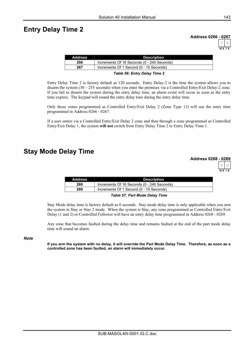
Solution 40 Installation Manual 143
SUB-MASOL40I-0001.IG.C.doc
Entry Delay Time 2 Address 0266 - 0267
7 816 S 1 S
Address Description
266 Increments Of 16 Seconds (0 - 240 Seconds) 267 Increments Of 1 Second (0 - 15 Seconds)
Table 56: Entry Delay Time 2
Entry Delay Time 2 is factory default as 120 seconds. Entry Delay-2 is the time the system allows you to disarm the system (30 – 255 seconds) when you enter the premises via a Controlled Entry/Exit Delay-2 zone. If you fail to disarm the system during the entry delay time, an alarm event will occur as soon as the entry time expires. The keypad will sound the entry delay tone during the entry delay time.
Only those zones programmed as Controlled Entry/Exit Delay 2 (Zone Type 12) will use the entry time programmed in Address 0266 - 0267. If a user enters via a Controlled Entry/Exit Delay 2 zone and then through a zone programmed as Controlled Entry/Exit Delay 1, the system will not switch from Entry Delay Time 2 to Entry Delay Time 1.
Stay Mode Delay Time Address 0268 - 0269
0 016 S 1 S
Address Description
268 Increments Of 16 Seconds (0 - 240 Seconds) 269 Increments Of 1 Second (0 - 15 Seconds)
Table 57: Part Mode Delay Time
Stay Mode delay time is factory default as 0 seconds. Stay mode delay time is only applicable when you arm the system in Stay or Stay 2 mode. When the system is Stay, any zone programmed as Controlled Entry/Exit Delay (1 and 2) or Controlled Follower will have an entry delay time programmed in Address 0268 - 0269. Any zone that becomes faulted during the delay time and remains faulted at the end of the part mode delay time will sound an alarm.
Note If you arm the system with no delay, it will override the Part Mode Delay Time. Therefore, as soon as a controlled zone has been faulted, an alarm will immediately occur.
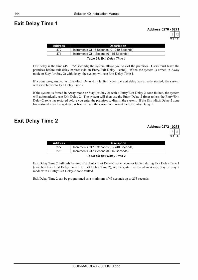
144 Solution 40 Installation Manual
SUB-MASOL40I-0001.IG.C.doc
Exit Delay Time 1 Address 0270 - 0271
3 1216 S 1 S
Address Description
270 Increments Of 16 Seconds (0 - 240 Seconds) 271 Increments Of 1 Second (0 - 15 Seconds)
Table 58: Exit Delay Time 1 Exit delay is the time (45 – 255 seconds) the system allows you to exit the premises. Users must leave the premises before exit delay expires (via an Entry/Exit Delay-1 zone). When the system is armed in Away mode or Stay (or Stay 2) with delay, the system will use Exit Delay Time 1. If a zone programmed as Entry/Exit Delay-2 is faulted when the exit delay has already started, the system will switch over to Exit Delay Time 2. If the system is forced in Away mode or Stay (or Stay 2) with a Entry/Exit Delay-2 zone faulted, the system will automatically use Exit Delay 2. The system will then use the Entry Delay-2 timer unless the Entry/Exit Delay-2 zone has restored before you enter the premises to disarm the system. If the Entry/Exit Delay-2 zone has restored after the system has been armed, the system will revert back to Entry Delay 1.
Exit Delay Time 2 Address 0272 - 0273
7 816 S 1 S
Address Description
272 Increments Of 16 Seconds (0 - 240 Seconds) 273 Increments Of 1 Second (0 - 15 Seconds)
Table 59: Exit Delay Time 2 Exit Delay Time 2 will only be used if an Entry/Exit Delay-2 zone becomes faulted during Exit Delay Time 1 (switches from Exit Delay Time 1 to Exit Delay Time 2), or, the system is forced in Away, Stay or Stay 2 mode with a Entry/Exit Delay-2 zone faulted. Exit Delay Time 2 can be programmed as a minimum of 45 seconds up to 255 seconds.

Solution 40 Installation Manual 145
SUB-MASOL40I-0001.IG.C.doc
Areas
Area 1 Account Number For Destination 1 Address 0276 - 0281
10 10 10 10 0 0
Each area can report to two different destinations, each destination having it's own (or same) account number. The account number you program here identifies to the security company which alarm system is reporting information. Programming From The Keypad Use the table below to program each address for the account number. Each address will hold one digit of the account number.
Account Digit Number To Program Account Digit Number To Program 1 1 9 9 2 2 0 10 3 3 B 11 4 4 C 12 5 5 D 13 6 6 E 14 7 7 F 15 8 8 Terminate 0
Table 60: Account Number Digit Selections
Area 1 Account Number For Destination 2 Address 0286 - 0291
10 10 10 10 0 0
Refer to Area 1 Account Number For Destination 1 above for more information.
Area 1 - Open/Close Report Options Address 0296
1
Option Description 0 No Open/Close Reports For Area 1 1 Open/Close Reports For Area 1 Allowed 2 Open Reports Only After Alarm/Close Reports Only On Force Arm 4 Open/Close Reports For Stay and Stay 2 mode 8 1 Second Siren Test On Closing Acknowledge
Table 61: Area 1 Open/Close Report Options
146 Solution 40 Installation Manual
SUB-MASOL40I-0001.IG.C.doc
Open/Close Reports For Area 1 Allowed If this option is programmed, ‘Open’ and ‘Close’ reports for Area 1 will be allowed to report. If this option is not programmed, ‘Open’ and ‘Close’ reports for Area 1 will not report. This option requires the following to be programmed to send open/close reports for Area 1: • Option 1 - Open Reports Allowed in Address 0261 on page 140. • Option 2 - Close Reports Allowed in Address 0261 on page 140. • Open/Close Report Routing in Address 0263 on page 141. • Only those PIN codes assigned to Authority Level Option 6 on page 159 will send Open/Close
reports.
Note If this option (Option 1) is not programmed, will disable the following reports for Area 1 – Auto On Extend [Equ 21], Closing [Equ 42 – 54], Forced Closing [Equ 55 – 67], Open [Equ 89 – 96], First To Open [Equ 164] and Last To Close [Equ 165].
Open Reports Only After Alarm/Close Reports Only On Force Arm If this option is programmed, an 'Open' report will only be sent when a user has disarmed the area after an alarm has occurred. A 'Close' report will only be sent if the system is forced on (Away, Stay or Stay 2). This option requires the following to be programmed to operate: • Option 1 - Open/Close Reports For Area 1 Allowed in Address 0296 on page 145. • Option 1 - Open Reports Allowed in Address 0261 on page 140. • Option 2 - Close Reports Allowed in Address 0261 on page 140. • Open/Close Report Routing in Address 0263 on page 141. • Open/Close reports disabled for each PIN code in Authority Level Option 6 on page 159 (Any PIN
code that has open/close reports allowed will always send open/close reports). • Only those PIN codes assigned to Authority Level Option 7 on page 159 can force arm the system.
Note If the option “Open Reports only after an Alarm / Close Reports Only on Force Arm” is enabled it overrides the “First to Open / Last to Close” option. Open/Close Reports For Stay and Stay 2 mode If this option is programmed, 'Open' and 'Close' reports will be sent when the system is armed in Stay or Stay 2 mode. If this option is not programmed, ‘Open’ and ‘Close’ reports will not be sent when the system is armed in Stay or Stay 2 mode. This option requires the following to be programmed to operate: • Option 1 - Open/Close Reports For Area 1 Allowed in Address 0296 on page 145. • Option 1 - Open Reports Allowed in Address 0261 on page 140. • Option 2 - Close Reports Allowed in Address 0261 on page 140. • Open/Close Report Routing in Address 0263 on page 141. • Only those PIN codes assigned to Authority Level Option 6 on page 159 will send Open/Close
reports. • Only those PIN codes assigned to Authority Level Option 2 on page 157 (arm in Stay mode) and
Authority Level Option 3 on page 158 (arm in Stay 2 mode) can arm the system in Stay and Stay 2 mode.
1 Second Siren Test On Closing Acknowledge If this option is programmed, the system will activate any output programmed with an output event type (1,8), (1,9) or (1,10) assigned to Area 1 for one second when exit time has expired.
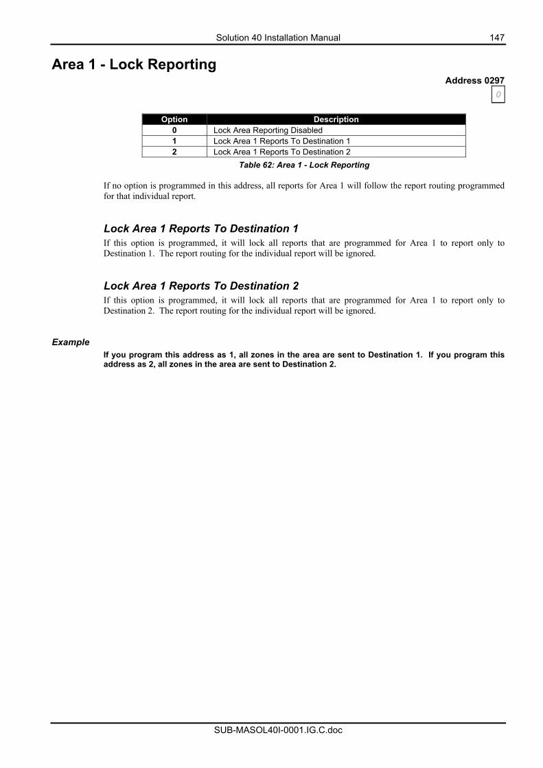
Solution 40 Installation Manual 147
SUB-MASOL40I-0001.IG.C.doc
Area 1 - Lock Reporting Address 0297
0
Option Description 0 Lock Area Reporting Disabled 1 Lock Area 1 Reports To Destination 1 2 Lock Area 1 Reports To Destination 2
Table 62: Area 1 - Lock Reporting
If no option is programmed in this address, all reports for Area 1 will follow the report routing programmed for that individual report.
Lock Area 1 Reports To Destination 1 If this option is programmed, it will lock all reports that are programmed for Area 1 to report only to Destination 1. The report routing for the individual report will be ignored. Lock Area 1 Reports To Destination 2 If this option is programmed, it will lock all reports that are programmed for Area 1 to report only to Destination 2. The report routing for the individual report will be ignored.
Example If you program this address as 1, all zones in the area are sent to Destination 1. If you program this address as 2, all zones in the area are sent to Destination 2.

148 Solution 40 Installation Manual
SUB-MASOL40I-0001.IG.C.doc
Area 2 Account Number For Destination 1 Address 0298 - 0303
10 10 10 10 0 0
Each Area can report to two different destinations, each destination having it's own (or same) account number. The account number you program here identifies to the security company which alarm system is reporting information. Programming From The Keypad Use the table below to program each address for the account number. Each address will hold one digit of the account number.
Account Digit Number To Program Account Digit Number To Program 1 1 9 9 2 2 0 10 3 3 B 11 4 4 C 12 5 5 D 13 6 6 E 14 7 7 F 15 8 8 Terminate 0
Table 63: Account Number Digit Selections
Area 2 Account Number For Destination 2 Address 0308 - 0313
10 10 10 10 0 0
Refer to Area 2 Account Number For Destination 1 above for more information.

Solution 40 Installation Manual 149
SUB-MASOL40I-0001.IG.C.doc
Area 2 - Open/Close Report Options Address 0318
1
Option Description 0 No Open/Close Reports For Area 2 1 Open/Close Reports For Area 2 Allowed 2 Open Reports Only After Alarm/Close Reports Only On Force Arm 4 Open/Close Reports For Stay and Stay 2 mode 8 1 Second Siren Test On Closing Acknowledge
Table 64: Area 2 - Open/Close Report Options
Open/Close Reports For Area 2 Allowed If this option is programmed, ‘Open’ and ‘Close’ reports for Area 2 will be allowed to report. If this option is not programmed, ‘Open’ and ‘Close’ reports for Area 2 will not report. This option requires the following to be programmed to send open/close reports for Area 2: • Option 1 - Open Reports Allowed in Address 0261 on page 140. • Option 2 - Close Reports Allowed in Address 0261 on page 140. • Open/Close Report Routing in Address 0263 on page 141. • Only those PIN codes assigned to Authority Level Option 6 on page 159 will send Open/Close
reports.
Note If this option (Option 1) is not programmed, will disable the following reports for Area 2 – Auto On Extend [Equ 21], Closing [Equ 42 – 54], Forced Closing [Equ 55 – 67], Open [Equ 89 – 96], First To Open [Equ 164] and Last To Close [Equ 165]. Open Reports Only After Alarm/Close Reports Only On Force Arm If this option is programmed, an 'Open' report will only be sent when a user has disarmed the area after an alarm has occurred. A 'Close' report will only be sent if the system is forced on (Away, Stay or Stay 2). This option requires the following to be programmed to operate: • Option 1 - Open/Close Reports For Area 2 Allowed in Address 0318 on page 149. • Option 1 - Open Reports Allowed in Address 0261 on page 140. • Option 2 - Close Reports Allowed in Address 0261 on page 140. • Open/Close Report Routing in Address 0263 on page 141. • Open/Close reports disabled for each PIN code in Authority Level Option 6 on page 159 (Any PIN
code that has open/close reports allowed will always send open/close reports). • Only those PIN codes assigned to Authority Level Option 7 on page 159 can force arm the system. Open/Close Reports For Stay and Stay 2 mode If this option is programmed, 'Open' and 'Close' reports will be sent when the system is armed in Stay or Stay 2 mode. If this option is not programmed, ‘Open’ and ‘Close’ reports will not be sent when the system is armed in Stay or Stay 2 mode. This option requires the following to be programmed to operate: • Option 1 - Open/Close Reports For Area 2 Allowed in Address 0318 on page 149. • Option 1 - Open Reports Allowed in Address 0261 on page 140. • Option 2 - Close Reports Allowed in Address 0261 on page 140. • Open/Close Report Routing in Address 0263 on page 141. • Only those PIN codes assigned to Authority Level Option 6 on page 159 will send Open/Close
reports. • Only those PIN codes assigned to Authority Level Option 2 on page 157 (arm in Stay mode) and
Authority Level Option 3 on page 158 (arm in Stay 2 mode) can arm the system in Stay and Stay 2 mode.
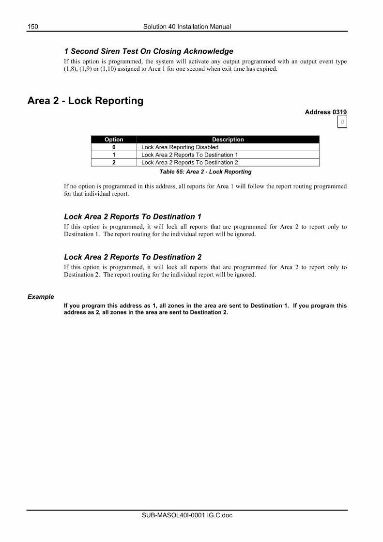
150 Solution 40 Installation Manual
SUB-MASOL40I-0001.IG.C.doc
1 Second Siren Test On Closing Acknowledge If this option is programmed, the system will activate any output programmed with an output event type (1,8), (1,9) or (1,10) assigned to Area 1 for one second when exit time has expired.
Area 2 - Lock Reporting Address 0319
0
Option Description 0 Lock Area Reporting Disabled 1 Lock Area 2 Reports To Destination 1 2 Lock Area 2 Reports To Destination 2
Table 65: Area 2 - Lock Reporting
If no option is programmed in this address, all reports for Area 1 will follow the report routing programmed for that individual report.
Lock Area 2 Reports To Destination 1 If this option is programmed, it will lock all reports that are programmed for Area 2 to report only to Destination 1. The report routing for the individual report will be ignored. Lock Area 2 Reports To Destination 2 If this option is programmed, it will lock all reports that are programmed for Area 2 to report only to Destination 2. The report routing for the individual report will be ignored.
Example If you program this address as 1, all zones in the area are sent to Destination 1. If you program this address as 2, all zones in the area are sent to Destination 2.
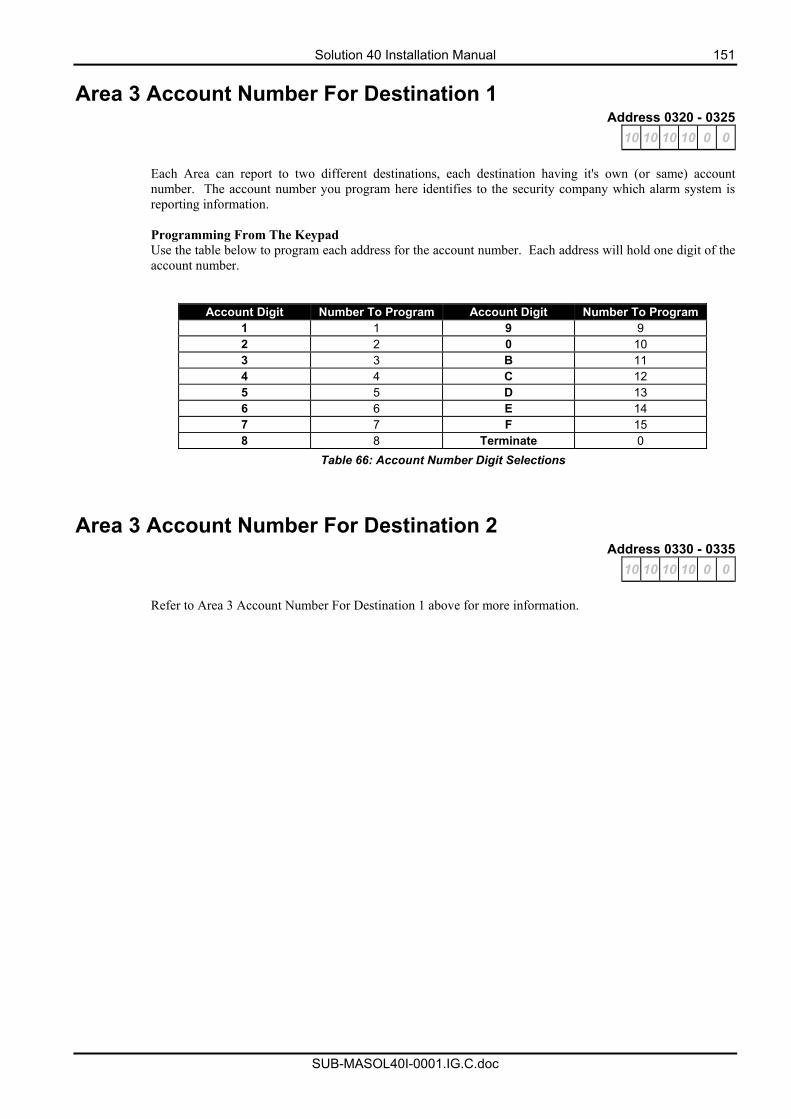
Solution 40 Installation Manual 151
SUB-MASOL40I-0001.IG.C.doc
Area 3 Account Number For Destination 1 Address 0320 - 0325
10 10 10 10 0 0
Each Area can report to two different destinations, each destination having it's own (or same) account number. The account number you program here identifies to the security company which alarm system is reporting information. Programming From The Keypad Use the table below to program each address for the account number. Each address will hold one digit of the account number.
Account Digit Number To Program Account Digit Number To Program 1 1 9 9 2 2 0 10 3 3 B 11 4 4 C 12 5 5 D 13 6 6 E 14 7 7 F 15 8 8 Terminate 0
Table 66: Account Number Digit Selections
Area 3 Account Number For Destination 2 Address 0330 - 0335
10 10 10 10 0 0
Refer to Area 3 Account Number For Destination 1 above for more information.
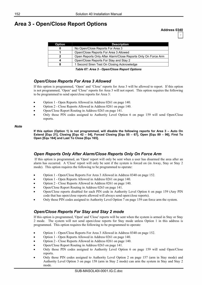
152 Solution 40 Installation Manual
SUB-MASOL40I-0001.IG.C.doc
Area 3 - Open/Close Report Options Address 0340
1
Option Description 0 No Open/Close Reports For Area 3 1 Open/Close Reports For Area 3 Allowed 2 Open Reports Only After Alarm/Close Reports Only On Force Arm 4 Open/Close Reports For Stay and Stay 2 8 1 Second Siren Test On Closing Acknowledge
Table 67: Area 3 - Open/Close Report Options
Open/Close Reports For Area 3 Allowed If this option is programmed, ‘Open’ and ‘Close’ reports for Area 3 will be allowed to report. If this option is not programmed, ‘Open’ and ‘Close’ reports for Area 3 will not report. This option requires the following to be programmed to send open/close reports for Area 3: • Option 1 - Open Reports Allowed in Address 0261 on page 140. • Option 2 - Close Reports Allowed in Address 0261 on page 140. • Open/Close Report Routing in Address 0263 on page 141. • Only those PIN codes assigned to Authority Level Option 6 on page 159 will send Open/Close
reports.
Note If this option (Option 1) is not programmed, will disable the following reports for Area 3 – Auto On Extend [Equ 21], Closing [Equ 42 – 54], Forced Closing [Equ 55 – 67], Open [Equ 89 – 96], First To Open [Equ 164] and Last To Close [Equ 165]. Open Reports Only After Alarm/Close Reports Only On Force Arm If this option is programmed, an 'Open' report will only be sent when a user has disarmed the area after an alarm has occurred. A 'Close' report will only be sent if the system is forced on (in Away, Stay or Stay 2 mode). This option requires the following to be programmed to operate: • Option 1 - Open/Close Reports For Area 3 Allowed in Address 0340 on page 152. • Option 1 - Open Reports Allowed in Address 0261 on page 140. • Option 2 - Close Reports Allowed in Address 0261 on page 140. • Open/Close Report Routing in Address 0263 on page 141. • Open/Close reports disabled for each PIN code in Authority Level Option 6 on page 159 (Any PIN
code that has open/close reports allowed will always send open/close reports). • Only those PIN codes assigned to Authority Level Option 7 on page 159 can force arm the system.
Open/Close Reports For Stay and Stay 2 mode If this option is programmed, 'Open' and 'Close' reports will be sent when the system is armed in Stay or Stay 2 mode. The system will not send open/close reports for Stay mode unless Option 1 in this address is programmed. This option requires the following to be programmed to operate: • Option 1 - Open/Close Reports For Area 3 Allowed in Address 0340 on page 152. • Option 1 - Open Reports Allowed in Address 0261 on page 140. • Option 2 - Close Reports Allowed in Address 0261 on page 140. • Open/Close Report Routing in Address 0263 on page 141. • Only those PIN codes assigned to Authority Level Option 6 on page 159 will send Open/Close
reports. • Only those PIN codes assigned to Authority Level Option 2 on page 157 (arm in Stay mode) and
Authority Level Option 3 on page 158 (arm in Stay 2 mode) can arm the system in Stay and Stay 2 mode.
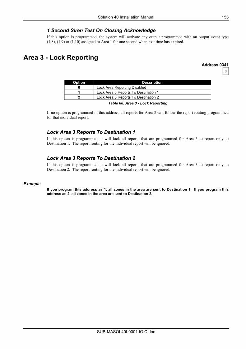
Solution 40 Installation Manual 153
SUB-MASOL40I-0001.IG.C.doc
1 Second Siren Test On Closing Acknowledge If this option is programmed, the system will activate any output programmed with an output event type (1,8), (1,9) or (1,10) assigned to Area 1 for one second when exit time has expired.
Area 3 - Lock Reporting Address 0341
0
Option Description 0 Lock Area Reporting Disabled 1 Lock Area 3 Reports To Destination 1 2 Lock Area 3 Reports To Destination 2
Table 68: Area 3 - Lock Reporting
If no option is programmed in this address, all reports for Area 3 will follow the report routing programmed for that individual report.
Lock Area 3 Reports To Destination 1 If this option is programmed, it will lock all reports that are programmed for Area 3 to report only to Destination 1. The report routing for the individual report will be ignored. Lock Area 3 Reports To Destination 2 If this option is programmed, it will lock all reports that are programmed for Area 3 to report only to Destination 2. The report routing for the individual report will be ignored.
Example If you program this address as 1, all zones in the area are sent to Destination 1. If you program this address as 2, all zones in the area are sent to Destination 2.
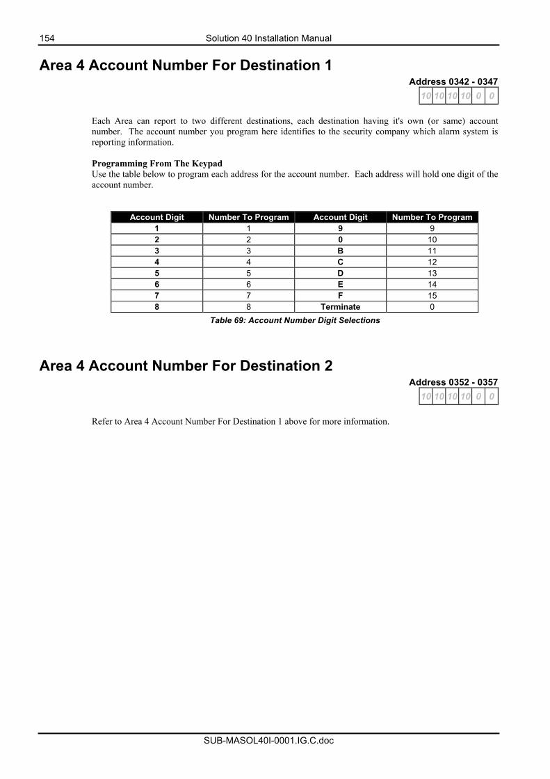
154 Solution 40 Installation Manual
SUB-MASOL40I-0001.IG.C.doc
Area 4 Account Number For Destination 1 Address 0342 - 0347
10 10 10 10 0 0
Each Area can report to two different destinations, each destination having it's own (or same) account number. The account number you program here identifies to the security company which alarm system is reporting information. Programming From The Keypad Use the table below to program each address for the account number. Each address will hold one digit of the account number.
Account Digit Number To Program Account Digit Number To Program 1 1 9 9 2 2 0 10 3 3 B 11 4 4 C 12 5 5 D 13 6 6 E 14 7 7 F 15 8 8 Terminate 0
Table 69: Account Number Digit Selections
Area 4 Account Number For Destination 2 Address 0352 - 0357
10 10 10 10 0 0
Refer to Area 4 Account Number For Destination 1 above for more information.
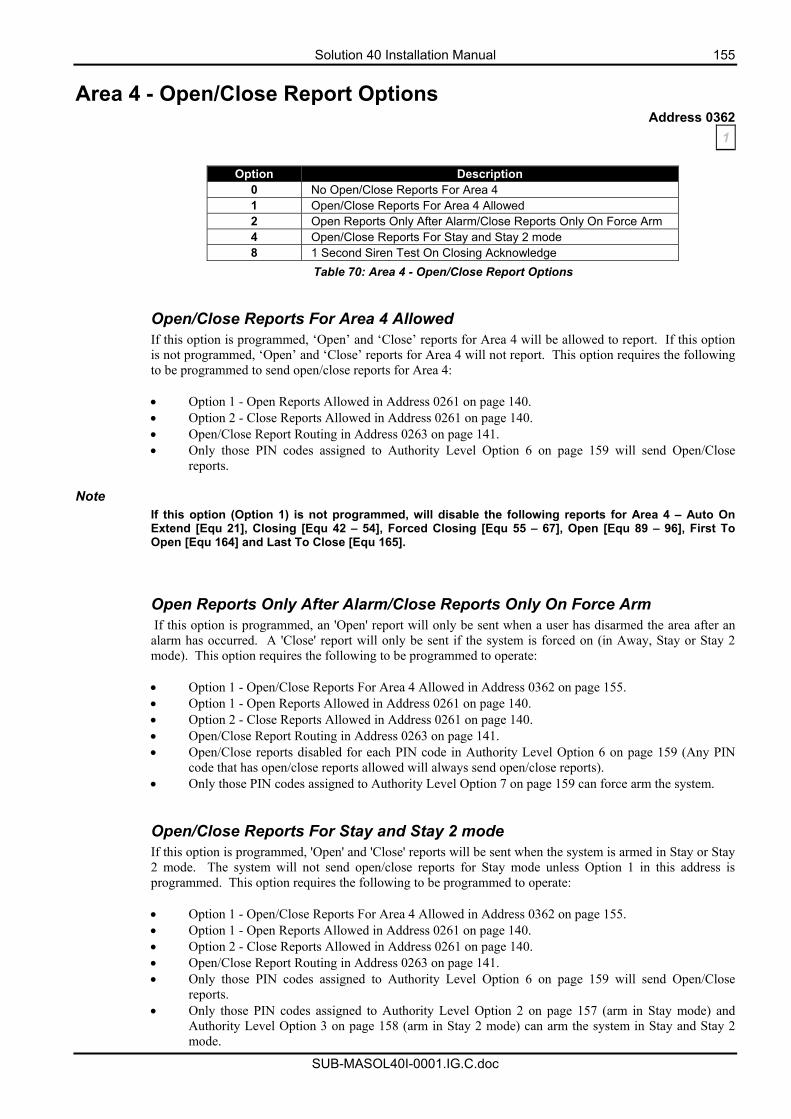
Solution 40 Installation Manual 155
SUB-MASOL40I-0001.IG.C.doc
Area 4 - Open/Close Report Options Address 0362
1
Option Description 0 No Open/Close Reports For Area 4 1 Open/Close Reports For Area 4 Allowed 2 Open Reports Only After Alarm/Close Reports Only On Force Arm 4 Open/Close Reports For Stay and Stay 2 mode 8 1 Second Siren Test On Closing Acknowledge
Table 70: Area 4 - Open/Close Report Options
Open/Close Reports For Area 4 Allowed If this option is programmed, ‘Open’ and ‘Close’ reports for Area 4 will be allowed to report. If this option is not programmed, ‘Open’ and ‘Close’ reports for Area 4 will not report. This option requires the following to be programmed to send open/close reports for Area 4: • Option 1 - Open Reports Allowed in Address 0261 on page 140. • Option 2 - Close Reports Allowed in Address 0261 on page 140. • Open/Close Report Routing in Address 0263 on page 141. • Only those PIN codes assigned to Authority Level Option 6 on page 159 will send Open/Close
reports.
Note If this option (Option 1) is not programmed, will disable the following reports for Area 4 – Auto On Extend [Equ 21], Closing [Equ 42 – 54], Forced Closing [Equ 55 – 67], Open [Equ 89 – 96], First To Open [Equ 164] and Last To Close [Equ 165]. Open Reports Only After Alarm/Close Reports Only On Force Arm If this option is programmed, an 'Open' report will only be sent when a user has disarmed the area after an alarm has occurred. A 'Close' report will only be sent if the system is forced on (in Away, Stay or Stay 2 mode). This option requires the following to be programmed to operate: • Option 1 - Open/Close Reports For Area 4 Allowed in Address 0362 on page 155. • Option 1 - Open Reports Allowed in Address 0261 on page 140. • Option 2 - Close Reports Allowed in Address 0261 on page 140. • Open/Close Report Routing in Address 0263 on page 141. • Open/Close reports disabled for each PIN code in Authority Level Option 6 on page 159 (Any PIN
code that has open/close reports allowed will always send open/close reports). • Only those PIN codes assigned to Authority Level Option 7 on page 159 can force arm the system. Open/Close Reports For Stay and Stay 2 mode If this option is programmed, 'Open' and 'Close' reports will be sent when the system is armed in Stay or Stay 2 mode. The system will not send open/close reports for Stay mode unless Option 1 in this address is programmed. This option requires the following to be programmed to operate: • Option 1 - Open/Close Reports For Area 4 Allowed in Address 0362 on page 155. • Option 1 - Open Reports Allowed in Address 0261 on page 140. • Option 2 - Close Reports Allowed in Address 0261 on page 140. • Open/Close Report Routing in Address 0263 on page 141. • Only those PIN codes assigned to Authority Level Option 6 on page 159 will send Open/Close
reports. • Only those PIN codes assigned to Authority Level Option 2 on page 157 (arm in Stay mode) and
Authority Level Option 3 on page 158 (arm in Stay 2 mode) can arm the system in Stay and Stay 2 mode.

156 Solution 40 Installation Manual
SUB-MASOL40I-0001.IG.C.doc
1 Second Siren Test On Closing Acknowledge If this option is programmed, the system will activate any output programmed with an output event type (1,8), (1,9) or (1,10) assigned to Area 1 for one second when exit time has expired.
Area 4 - Lock Reporting Address 0363
0
Option Description 0 Lock Area Reporting Disabled 1 Lock Area 4 Reports To Destination 1 2 Lock Area 4 Reports To Destination 2
Table 71: Area 4 - Lock Reporting
If no option is programmed in this address, all reports for Area 4 will follow the report routing programmed for that individual report.
Lock Area 4 Reports To Destination 1 If this option is programmed, it will lock all reports that are programmed for Area 4 to report only to Destination 1. The report routing for the individual report will be ignored. Lock Area 4 Reports To Destination 2 If this option is programmed, it will lock all reports that are programmed for Area 4 to report only to Destination 2. The report routing for the individual report will be ignored.
Example If you program this address as 1, all zones in the area are sent to Destination 1. If you program this address as 2, all zones in the area are sent to Destination 2.
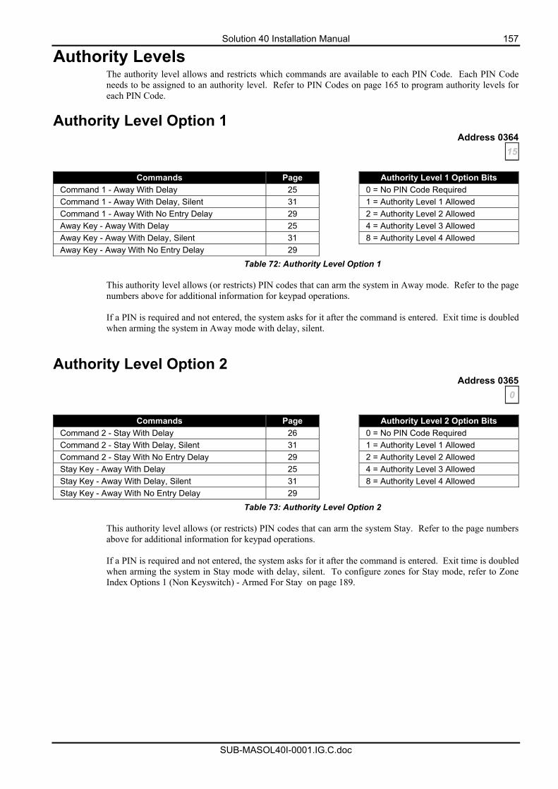
Solution 40 Installation Manual 157
SUB-MASOL40I-0001.IG.C.doc
Authority Levels The authority level allows and restricts which commands are available to each PIN Code. Each PIN Code needs to be assigned to an authority level. Refer to PIN Codes on page 165 to program authority levels for each PIN Code.
Authority Level Option 1 Address 0364
15
Commands Page Authority Level 1 Option Bits Command 1 - Away With Delay 25 0 = No PIN Code Required Command 1 - Away With Delay, Silent 31 1 = Authority Level 1 Allowed Command 1 - Away With No Entry Delay 29 2 = Authority Level 2 Allowed Away Key - Away With Delay 25 4 = Authority Level 3 Allowed Away Key - Away With Delay, Silent 31 8 = Authority Level 4 Allowed Away Key - Away With No Entry Delay 29
Table 72: Authority Level Option 1
This authority level allows (or restricts) PIN codes that can arm the system in Away mode. Refer to the page numbers above for additional information for keypad operations. If a PIN is required and not entered, the system asks for it after the command is entered. Exit time is doubled when arming the system in Away mode with delay, silent.
Authority Level Option 2 Address 0365
0
Commands Page Authority Level 2 Option Bits Command 2 - Stay With Delay 26 0 = No PIN Code Required Command 2 - Stay With Delay, Silent 31 1 = Authority Level 1 Allowed Command 2 - Stay With No Entry Delay 29 2 = Authority Level 2 Allowed Stay Key - Away With Delay 25 4 = Authority Level 3 Allowed Stay Key - Away With Delay, Silent 31 8 = Authority Level 4 Allowed Stay Key - Away With No Entry Delay 29
Table 73: Authority Level Option 2
This authority level allows (or restricts) PIN codes that can arm the system Stay. Refer to the page numbers above for additional information for keypad operations. If a PIN is required and not entered, the system asks for it after the command is entered. Exit time is doubled when arming the system in Stay mode with delay, silent. To configure zones for Stay mode, refer to Zone Index Options 1 (Non Keyswitch) - Armed For Stay on page 189.
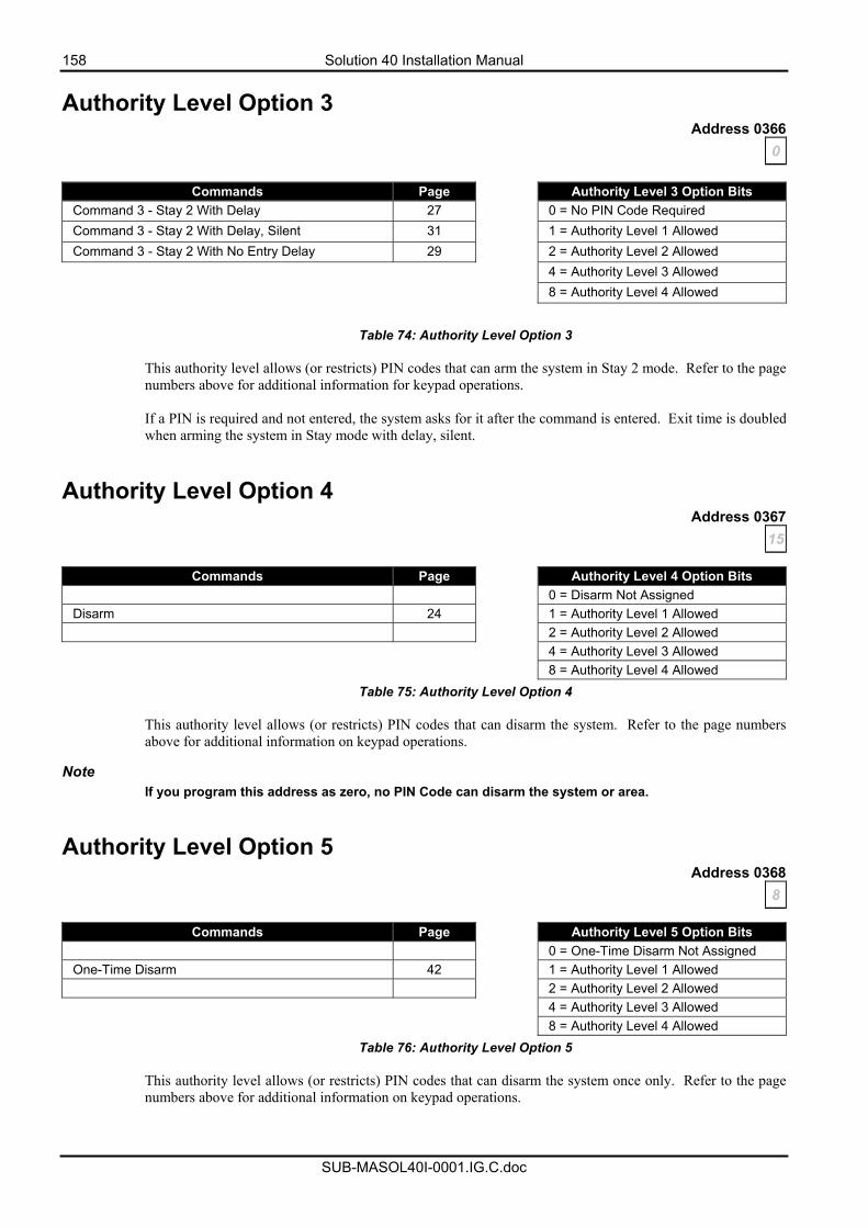
158 Solution 40 Installation Manual
SUB-MASOL40I-0001.IG.C.doc
Authority Level Option 3 Address 0366
0
Commands Page Authority Level 3 Option Bits Command 3 - Stay 2 With Delay 27 0 = No PIN Code Required Command 3 - Stay 2 With Delay, Silent 31 1 = Authority Level 1 Allowed Command 3 - Stay 2 With No Entry Delay 29 2 = Authority Level 2 Allowed 4 = Authority Level 3 Allowed 8 = Authority Level 4 Allowed
Table 74: Authority Level Option 3
This authority level allows (or restricts) PIN codes that can arm the system in Stay 2 mode. Refer to the page numbers above for additional information for keypad operations. If a PIN is required and not entered, the system asks for it after the command is entered. Exit time is doubled when arming the system in Stay mode with delay, silent.
Authority Level Option 4 Address 0367
15
Commands Page Authority Level 4 Option Bits 0 = Disarm Not Assigned Disarm 24 1 = Authority Level 1 Allowed 2 = Authority Level 2 Allowed 4 = Authority Level 3 Allowed 8 = Authority Level 4 Allowed
Table 75: Authority Level Option 4
This authority level allows (or restricts) PIN codes that can disarm the system. Refer to the page numbers above for additional information on keypad operations.
Note
If you program this address as zero, no PIN Code can disarm the system or area.
Authority Level Option 5 Address 0368
8
Commands Page Authority Level 5 Option Bits 0 = One-Time Disarm Not Assigned One-Time Disarm 42 1 = Authority Level 1 Allowed 2 = Authority Level 2 Allowed 4 = Authority Level 3 Allowed 8 = Authority Level 4 Allowed
Table 76: Authority Level Option 5
This authority level allows (or restricts) PIN codes that can disarm the system once only. Refer to the page numbers above for additional information on keypad operations.
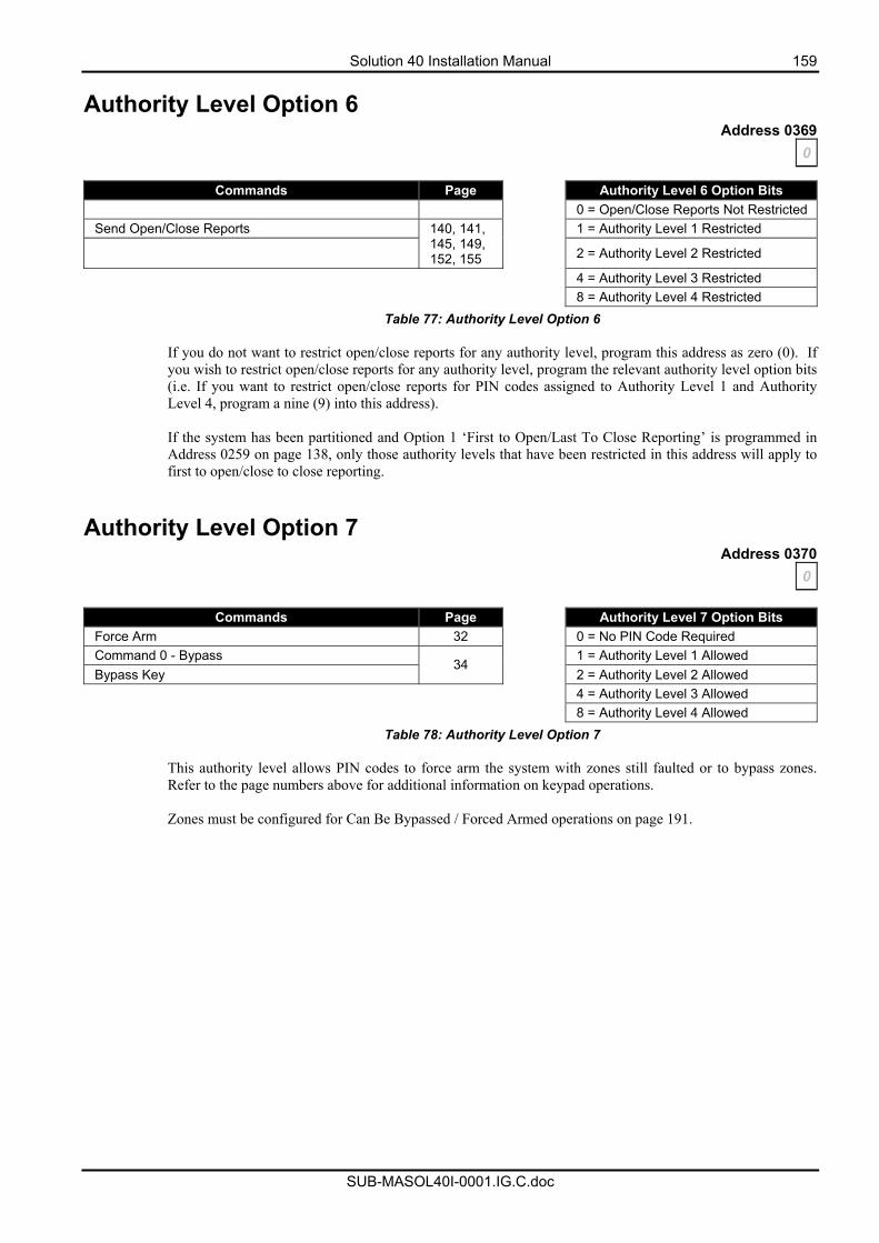
Solution 40 Installation Manual 159
SUB-MASOL40I-0001.IG.C.doc
Authority Level Option 6 Address 0369
0
Commands Page Authority Level 6 Option Bits 0 = Open/Close Reports Not Restricted Send Open/Close Reports 1 = Authority Level 1 Restricted
140, 141, 145, 149, 152, 155
2 = Authority Level 2 Restricted
4 = Authority Level 3 Restricted 8 = Authority Level 4 Restricted
Table 77: Authority Level Option 6
If you do not want to restrict open/close reports for any authority level, program this address as zero (0). If you wish to restrict open/close reports for any authority level, program the relevant authority level option bits (i.e. If you want to restrict open/close reports for PIN codes assigned to Authority Level 1 and Authority Level 4, program a nine (9) into this address). If the system has been partitioned and Option 1 ‘First to Open/Last To Close Reporting’ is programmed in Address 0259 on page 138, only those authority levels that have been restricted in this address will apply to first to open/close to close reporting.
Authority Level Option 7 Address 0370
0
Commands Page Authority Level 7 Option Bits Force Arm 32 0 = No PIN Code Required Command 0 - Bypass 1 = Authority Level 1 Allowed Bypass Key
34 2 = Authority Level 2 Allowed
4 = Authority Level 3 Allowed 8 = Authority Level 4 Allowed
Table 78: Authority Level Option 7
This authority level allows PIN codes to force arm the system with zones still faulted or to bypass zones. Refer to the page numbers above for additional information on keypad operations. Zones must be configured for Can Be Bypassed / Forced Armed operations on page 191.
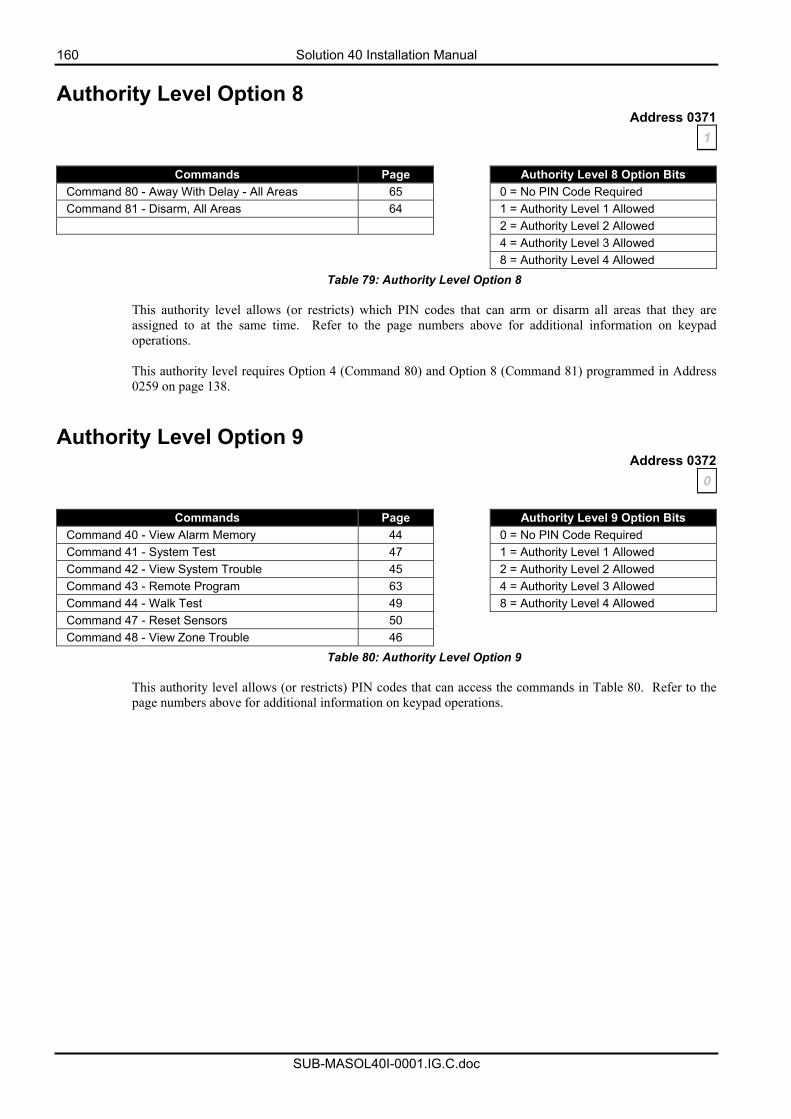
160 Solution 40 Installation Manual
SUB-MASOL40I-0001.IG.C.doc
Authority Level Option 8 Address 0371
1
Commands Page Authority Level 8 Option Bits Command 80 - Away With Delay - All Areas 65 0 = No PIN Code Required Command 81 - Disarm, All Areas 64 1 = Authority Level 1 Allowed 2 = Authority Level 2 Allowed 4 = Authority Level 3 Allowed 8 = Authority Level 4 Allowed
Table 79: Authority Level Option 8
This authority level allows (or restricts) which PIN codes that can arm or disarm all areas that they are assigned to at the same time. Refer to the page numbers above for additional information on keypad operations. This authority level requires Option 4 (Command 80) and Option 8 (Command 81) programmed in Address 0259 on page 138.
Authority Level Option 9 Address 0372
0
Commands Page Authority Level 9 Option Bits Command 40 - View Alarm Memory 44 0 = No PIN Code Required Command 41 - System Test 47 1 = Authority Level 1 Allowed Command 42 - View System Trouble 45 2 = Authority Level 2 Allowed Command 43 - Remote Program 63 4 = Authority Level 3 Allowed Command 44 - Walk Test 49 8 = Authority Level 4 Allowed Command 47 - Reset Sensors 50 Command 48 - View Zone Trouble 46
Table 80: Authority Level Option 9
This authority level allows (or restricts) PIN codes that can access the commands in Table 80. Refer to the page numbers above for additional information on keypad operations.
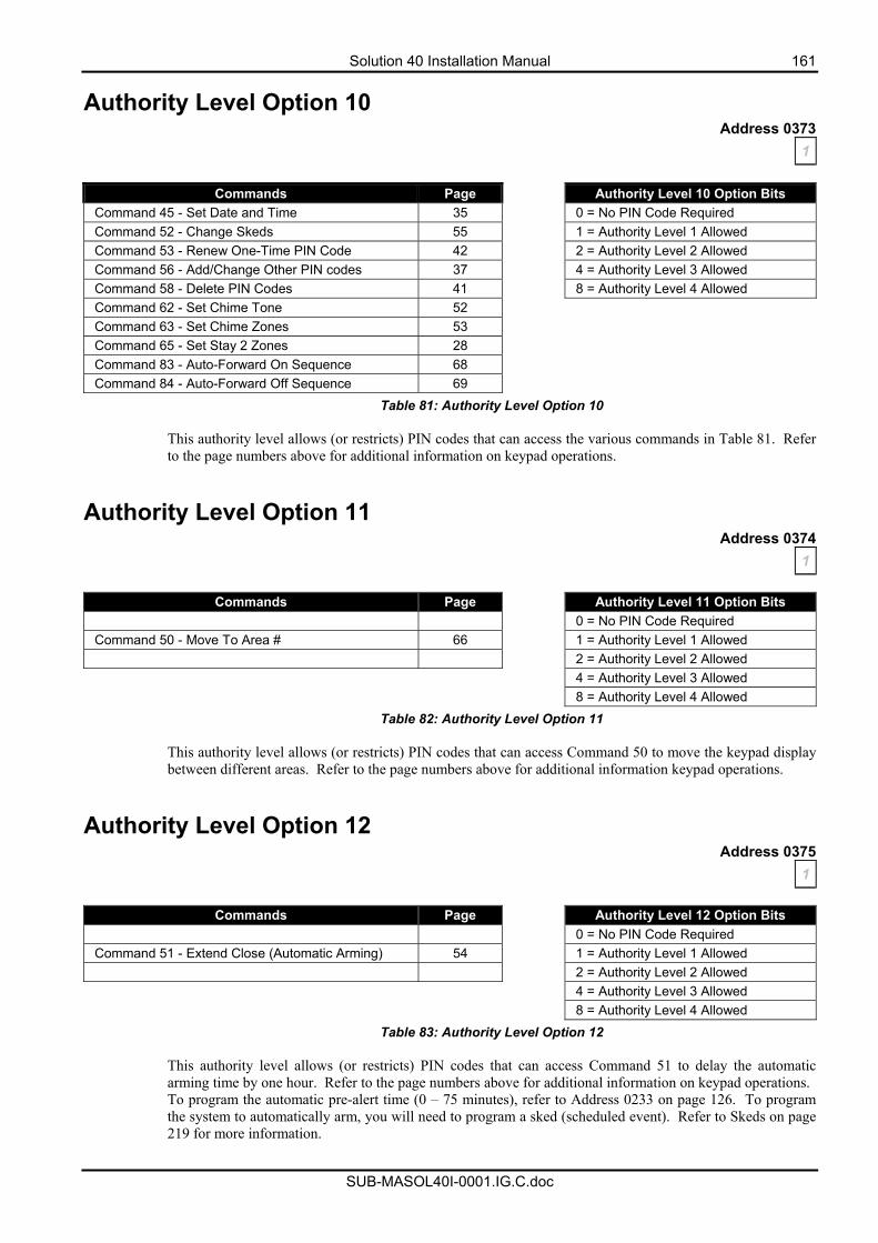
Solution 40 Installation Manual 161
SUB-MASOL40I-0001.IG.C.doc
Authority Level Option 10 Address 0373
1
Commands Page Authority Level 10 Option Bits Command 45 - Set Date and Time 35 0 = No PIN Code Required Command 52 - Change Skeds 55 1 = Authority Level 1 Allowed Command 53 - Renew One-Time PIN Code 42 2 = Authority Level 2 Allowed Command 56 - Add/Change Other PIN codes 37 4 = Authority Level 3 Allowed Command 58 - Delete PIN Codes 41 8 = Authority Level 4 Allowed Command 62 - Set Chime Tone 52 Command 63 - Set Chime Zones 53 Command 65 - Set Stay 2 Zones 28 Command 83 - Auto-Forward On Sequence 68 Command 84 - Auto-Forward Off Sequence 69
Table 81: Authority Level Option 10
This authority level allows (or restricts) PIN codes that can access the various commands in Table 81. Refer to the page numbers above for additional information on keypad operations.
Authority Level Option 11 Address 0374
1
Commands Page Authority Level 11 Option Bits 0 = No PIN Code Required Command 50 - Move To Area # 66 1 = Authority Level 1 Allowed 2 = Authority Level 2 Allowed 4 = Authority Level 3 Allowed 8 = Authority Level 4 Allowed
Table 82: Authority Level Option 11
This authority level allows (or restricts) PIN codes that can access Command 50 to move the keypad display between different areas. Refer to the page numbers above for additional information keypad operations.
Authority Level Option 12 Address 0375
1
Commands Page Authority Level 12 Option Bits 0 = No PIN Code Required Command 51 - Extend Close (Automatic Arming) 54 1 = Authority Level 1 Allowed 2 = Authority Level 2 Allowed 4 = Authority Level 3 Allowed 8 = Authority Level 4 Allowed
Table 83: Authority Level Option 12
This authority level allows (or restricts) PIN codes that can access Command 51 to delay the automatic arming time by one hour. Refer to the page numbers above for additional information on keypad operations. To program the automatic pre-alert time (0 – 75 minutes), refer to Address 0233 on page 126. To program the system to automatically arm, you will need to program a sked (scheduled event). Refer to Skeds on page 219 for more information.
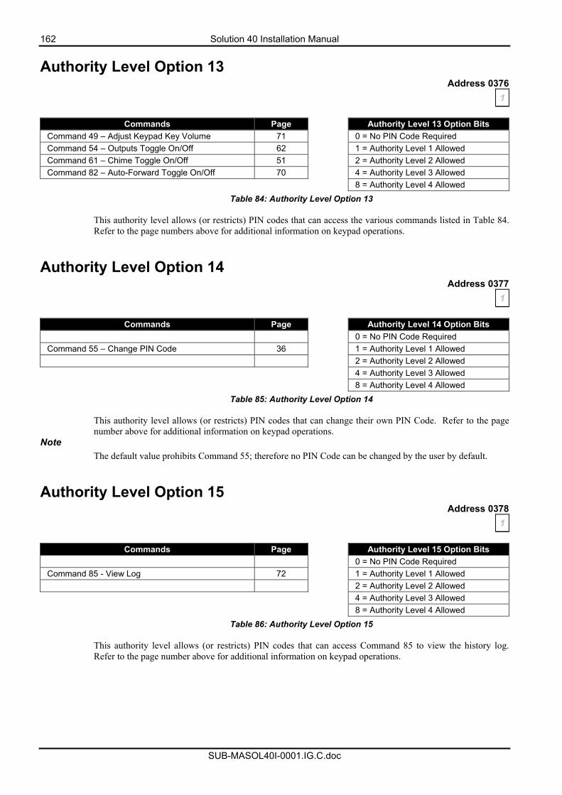
162 Solution 40 Installation Manual
SUB-MASOL40I-0001.IG.C.doc
Authority Level Option 13 Address 0376
1
Commands Page Authority Level 13 Option Bits Command 49 – Adjust Keypad Key Volume 71 0 = No PIN Code Required Command 54 – Outputs Toggle On/Off 62 1 = Authority Level 1 Allowed Command 61 – Chime Toggle On/Off 51 2 = Authority Level 2 Allowed Command 82 – Auto-Forward Toggle On/Off 70 4 = Authority Level 3 Allowed 8 = Authority Level 4 Allowed
Table 84: Authority Level Option 13
This authority level allows (or restricts) PIN codes that can access the various commands listed in Table 84. Refer to the page numbers above for additional information on keypad operations.
Authority Level Option 14 Address 0377
1
Commands Page Authority Level 14 Option Bits 0 = No PIN Code Required Command 55 – Change PIN Code 36 1 = Authority Level 1 Allowed 2 = Authority Level 2 Allowed 4 = Authority Level 3 Allowed 8 = Authority Level 4 Allowed
Table 85: Authority Level Option 14 This authority level allows (or restricts) PIN codes that can change their own PIN Code. Refer to the page number above for additional information on keypad operations.
Note The default value prohibits Command 55; therefore no PIN Code can be changed by the user by default.
Authority Level Option 15 Address 0378
1
Commands Page Authority Level 15 Option Bits 0 = No PIN Code Required Command 85 - View Log 72 1 = Authority Level 1 Allowed 2 = Authority Level 2 Allowed 4 = Authority Level 3 Allowed 8 = Authority Level 4 Allowed
Table 86: Authority Level Option 15
This authority level allows (or restricts) PIN codes that can access Command 85 to view the history log. Refer to the page number above for additional information on keypad operations.
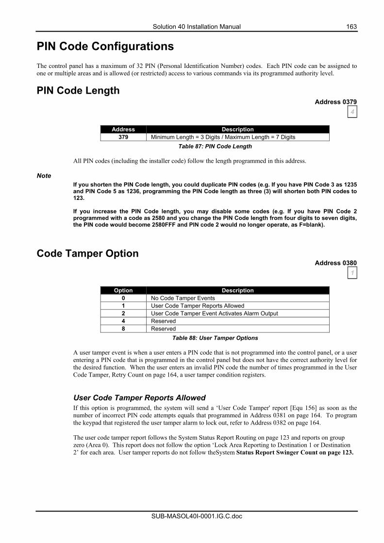
Solution 40 Installation Manual 163
SUB-MASOL40I-0001.IG.C.doc
PIN Code Configurations The control panel has a maximum of 32 PIN (Personal Identification Number) codes. Each PIN code can be assigned to one or multiple areas and is allowed (or restricted) access to various commands via its programmed authority level.
PIN Code Length Address 0379
4
Address Description 379 Minimum Length = 3 Digits / Maximum Length = 7 Digits
Table 87: PIN Code Length
All PIN codes (including the installer code) follow the length programmed in this address. Note
If you shorten the PIN Code length, you could duplicate PIN codes (e.g. If you have PIN Code 3 as 1235 and PIN Code 5 as 1236, programming the PIN Code length as three (3) will shorten both PIN codes to 123. If you increase the PIN Code length, you may disable some codes (e.g. If you have PIN Code 2 programmed with a code as 2580 and you change the PIN Code length from four digits to seven digits, the PIN code would become 2580FFF and PIN code 2 would no longer operate, as F=blank).
Code Tamper Option
Address 0380 1
Option Description
0 No Code Tamper Events 1 User Code Tamper Reports Allowed 2 User Code Tamper Event Activates Alarm Output 4 Reserved 8 Reserved
Table 88: User Tamper Options
A user tamper event is when a user enters a PIN code that is not programmed into the control panel, or a user entering a PIN code that is programmed in the control panel but does not have the correct authority level for the desired function. When the user enters an invalid PIN code the number of times programmed in the User Code Tamper, Retry Count on page 164, a user tamper condition registers.
User Code Tamper Reports Allowed If this option is programmed, the system will send a ‘User Code Tamper' report [Equ 156] as soon as the number of incorrect PIN code attempts equals that programmed in Address 0381 on page 164. To program the keypad that registered the user tamper alarm to lock out, refer to Address 0382 on page 164. The user code tamper report follows the System Status Report Routing on page 123 and reports on group zero (Area 0). This report does not follow the option ‘Lock Area Reporting to Destination 1 or Destination 2’ for each area. User tamper reports do not follow theSystem Status Report Swinger Count on page 123.
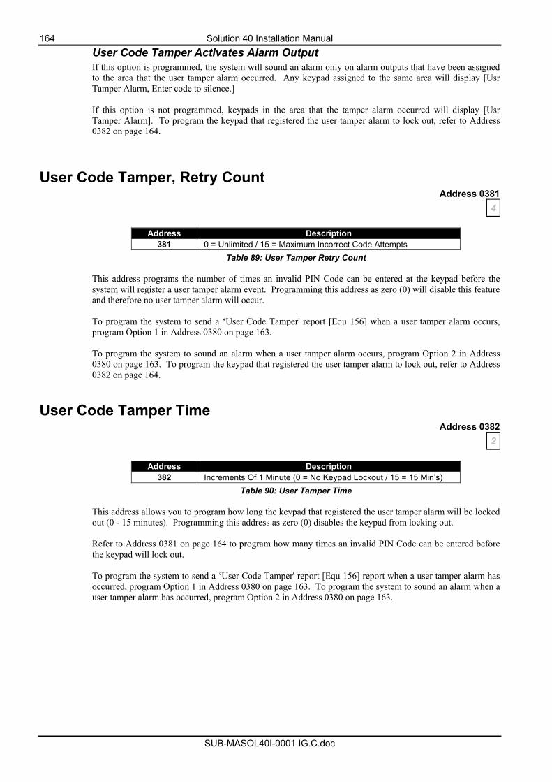
164 Solution 40 Installation Manual
SUB-MASOL40I-0001.IG.C.doc
User Code Tamper Activates Alarm Output If this option is programmed, the system will sound an alarm only on alarm outputs that have been assigned to the area that the user tamper alarm occurred. Any keypad assigned to the same area will display [Usr Tamper Alarm, Enter code to silence.] If this option is not programmed, keypads in the area that the tamper alarm occurred will display [Usr Tamper Alarm]. To program the keypad that registered the user tamper alarm to lock out, refer to Address 0382 on page 164.
User Code Tamper, Retry Count Address 0381
4
Address Description 381 0 = Unlimited / 15 = Maximum Incorrect Code Attempts
Table 89: User Tamper Retry Count
This address programs the number of times an invalid PIN Code can be entered at the keypad before the system will register a user tamper alarm event. Programming this address as zero (0) will disable this feature and therefore no user tamper alarm will occur. To program the system to send a ‘User Code Tamper' report [Equ 156] when a user tamper alarm occurs, program Option 1 in Address 0380 on page 163.
To program the system to sound an alarm when a user tamper alarm occurs, program Option 2 in Address 0380 on page 163. To program the keypad that registered the user tamper alarm to lock out, refer to Address 0382 on page 164.
User Code Tamper Time Address 0382
2
Address Description 382 Increments Of 1 Minute (0 = No Keypad Lockout / 15 = 15 Min’s)
Table 90: User Tamper Time
This address allows you to program how long the keypad that registered the user tamper alarm will be locked out (0 - 15 minutes). Programming this address as zero (0) disables the keypad from locking out. Refer to Address 0381 on page 164 to program how many times an invalid PIN Code can be entered before the keypad will lock out. To program the system to send a ‘User Code Tamper' report [Equ 156] report when a user tamper alarm has occurred, program Option 1 in Address 0380 on page 163. To program the system to sound an alarm when a user tamper alarm has occurred, program Option 2 in Address 0380 on page 163.
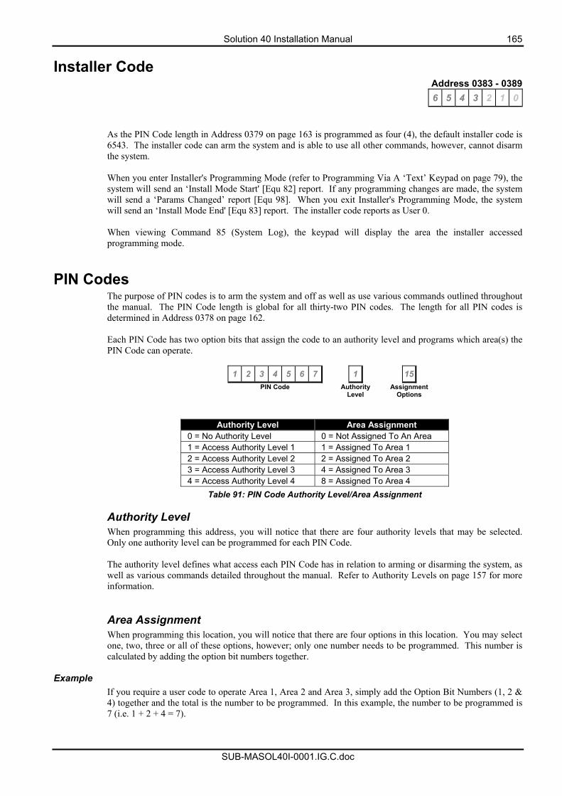
Solution 40 Installation Manual 165
SUB-MASOL40I-0001.IG.C.doc
Installer Code Address 0383 - 0389 6 5 4 3 2 1 0
As the PIN Code length in Address 0379 on page 163 is programmed as four (4), the default installer code is 6543. The installer code can arm the system and is able to use all other commands, however, cannot disarm the system. When you enter Installer's Programming Mode (refer to Programming Via A ‘Text’ Keypad on page 79), the system will send an ‘Install Mode Start' [Equ 82] report. If any programming changes are made, the system will send a ‘Params Changed’ report [Equ 98]. When you exit Installer's Programming Mode, the system will send an ‘Install Mode End' [Equ 83] report. The installer code reports as User 0. When viewing Command 85 (System Log), the keypad will display the area the installer accessed programming mode.
PIN Codes The purpose of PIN codes is to arm the system and off as well as use various commands outlined throughout the manual. The PIN Code length is global for all thirty-two PIN codes. The length for all PIN codes is determined in Address 0378 on page 162. Each PIN Code has two option bits that assign the code to an authority level and programs which area(s) the PIN Code can operate.
1 2 3 4 5 6 7 1 15 PIN Code Authority
Level Assignment
Options
Authority Level Area Assignment 0 = No Authority Level 0 = Not Assigned To An Area 1 = Access Authority Level 1 1 = Assigned To Area 1 2 = Access Authority Level 2 2 = Assigned To Area 2 3 = Access Authority Level 3 4 = Assigned To Area 3 4 = Access Authority Level 4 8 = Assigned To Area 4
Table 91: PIN Code Authority Level/Area Assignment
Authority Level When programming this address, you will notice that there are four authority levels that may be selected. Only one authority level can be programmed for each PIN Code. The authority level defines what access each PIN Code has in relation to arming or disarming the system, as well as various commands detailed throughout the manual. Refer to Authority Levels on page 157 for more information.
Area Assignment When programming this location, you will notice that there are four options in this location. You may select one, two, three or all of these options, however; only one number needs to be programmed. This number is calculated by adding the option bit numbers together.
Example
If you require a user code to operate Area 1, Area 2 and Area 3, simply add the Option Bit Numbers (1, 2 & 4) together and the total is the number to be programmed. In this example, the number to be programmed is 7 (i.e. 1 + 2 + 4 = 7).
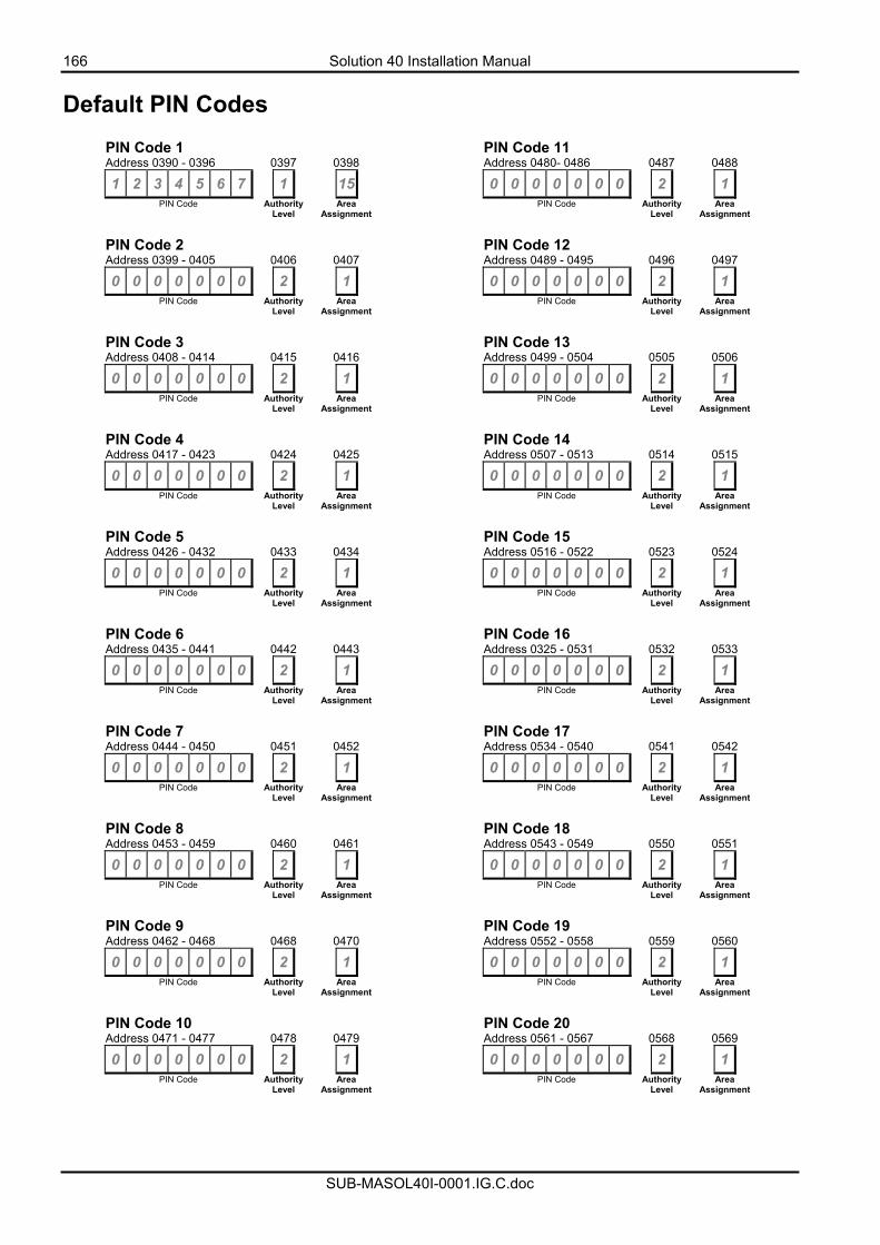
166 Solution 40 Installation Manual
SUB-MASOL40I-0001.IG.C.doc
Default PIN Codes PIN Code 1 PIN Code 11 Address 0390 - 0396 0397 0398 Address 0480- 0486 0487 0488 1 2 3 4 5 6 7 1 15 0 0 0 0 0 0 0 2 1
PIN Code Authority Level
Area Assignment PIN Code Authority
Level Area
Assignment PIN Code 2 PIN Code 12 Address 0399 - 0405 0406 0407 Address 0489 - 0495 0496 0497 0 0 0 0 0 0 0 2 1 0 0 0 0 0 0 0 2 1
PIN Code Authority Level
Area Assignment PIN Code Authority
Level Area
Assignment PIN Code 3 PIN Code 13 Address 0408 - 0414 0415 0416 Address 0499 - 0504 0505 0506 0 0 0 0 0 0 0 2 1 0 0 0 0 0 0 0 2 1
PIN Code Authority Level
Area Assignment PIN Code Authority
Level Area
Assignment PIN Code 4 PIN Code 14 Address 0417 - 0423 0424 0425 Address 0507 - 0513 0514 0515 0 0 0 0 0 0 0 2 1 0 0 0 0 0 0 0 2 1
PIN Code Authority Level
Area Assignment PIN Code Authority
Level Area
Assignment PIN Code 5 PIN Code 15 Address 0426 - 0432 0433 0434 Address 0516 - 0522 0523 0524 0 0 0 0 0 0 0 2 1 0 0 0 0 0 0 0 2 1
PIN Code Authority Level
Area Assignment PIN Code Authority
Level Area
Assignment PIN Code 6 PIN Code 16 Address 0435 - 0441 0442 0443 Address 0325 - 0531 0532 0533 0 0 0 0 0 0 0 2 1 0 0 0 0 0 0 0 2 1
PIN Code Authority Level
Area Assignment PIN Code Authority
Level Area
Assignment PIN Code 7 PIN Code 17 Address 0444 - 0450 0451 0452 Address 0534 - 0540 0541 0542 0 0 0 0 0 0 0 2 1 0 0 0 0 0 0 0 2 1
PIN Code Authority Level
Area Assignment PIN Code Authority
Level Area
Assignment PIN Code 8 PIN Code 18 Address 0453 - 0459 0460 0461 Address 0543 - 0549 0550 0551 0 0 0 0 0 0 0 2 1 0 0 0 0 0 0 0 2 1
PIN Code Authority Level
Area Assignment PIN Code Authority
Level Area
Assignment PIN Code 9 PIN Code 19 Address 0462 - 0468 0468 0470 Address 0552 - 0558 0559 0560 0 0 0 0 0 0 0 2 1 0 0 0 0 0 0 0 2 1
PIN Code Authority Level
Area Assignment PIN Code Authority
Level Area
Assignment PIN Code 10 PIN Code 20 Address 0471 - 0477 0478 0479 Address 0561 - 0567 0568 0569 0 0 0 0 0 0 0 2 1 0 0 0 0 0 0 0 2 1
PIN Code Authority Level
Area Assignment PIN Code Authority
Level Area
Assignment
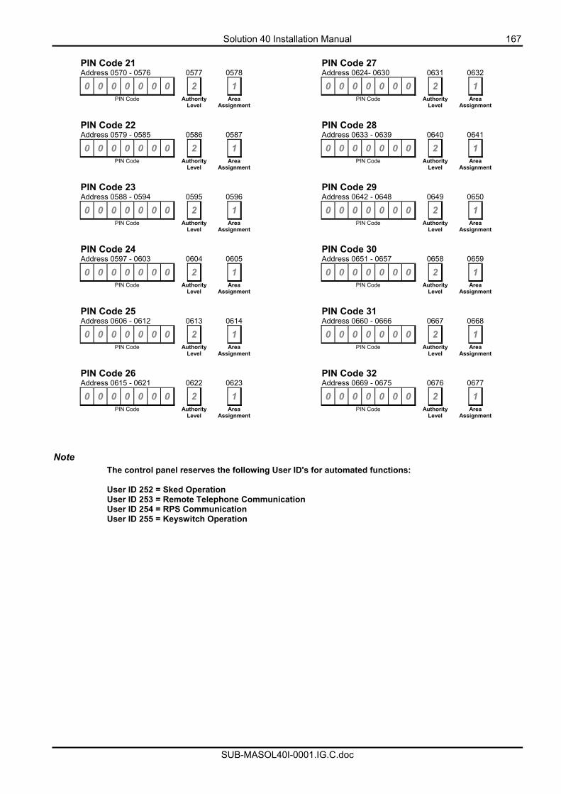
Solution 40 Installation Manual 167
SUB-MASOL40I-0001.IG.C.doc
PIN Code 21 PIN Code 27 Address 0570 - 0576 0577 0578 Address 0624- 0630 0631 0632 0 0 0 0 0 0 0 2 1 0 0 0 0 0 0 0 2 1
PIN Code Authority Level
Area Assignment PIN Code Authority
Level Area
Assignment PIN Code 22 PIN Code 28 Address 0579 - 0585 0586 0587 Address 0633 - 0639 0640 0641 0 0 0 0 0 0 0 2 1 0 0 0 0 0 0 0 2 1
PIN Code Authority Level
Area Assignment PIN Code Authority
Level Area
Assignment PIN Code 23 PIN Code 29 Address 0588 - 0594 0595 0596 Address 0642 - 0648 0649 0650 0 0 0 0 0 0 0 2 1 0 0 0 0 0 0 0 2 1
PIN Code Authority Level
Area Assignment PIN Code Authority
Level Area
Assignment PIN Code 24 PIN Code 30 Address 0597 - 0603 0604 0605 Address 0651 - 0657 0658 0659 0 0 0 0 0 0 0 2 1 0 0 0 0 0 0 0 2 1
PIN Code Authority Level
Area Assignment PIN Code Authority
Level Area
Assignment PIN Code 25 PIN Code 31 Address 0606 - 0612 0613 0614 Address 0660 - 0666 0667 0668 0 0 0 0 0 0 0 2 1 0 0 0 0 0 0 0 2 1
PIN Code Authority Level
Area Assignment PIN Code Authority
Level Area
Assignment PIN Code 26 PIN Code 32 Address 0615 - 0621 0622 0623 Address 0669 - 0675 0676 0677 0 0 0 0 0 0 0 2 1 0 0 0 0 0 0 0 2 1
PIN Code Authority Level
Area Assignment PIN Code Authority
Level Area
Assignment
Note The control panel reserves the following User ID's for automated functions: User ID 252 = Sked Operation User ID 253 = Remote Telephone Communication User ID 254 = RPS Communication User ID 255 = Keyswitch Operation
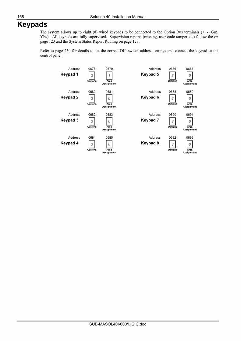
168 Solution 40 Installation Manual
SUB-MASOL40I-0001.IG.C.doc
Keypads The system allows up to eight (8) wired keypads to be connected to the Option Bus terminals (+, -, Grn, Ylw). All keypads are fully supervised. Supervision reports (missing, user code tamper etc) follow the on page 123 and the System Status Report Routing on page 123. Refer to page 250 for details to set the correct DIP switch address settings and connect the keypad to the control panel.
Address 0678 0679 Address 0686 0687
Keypad 1 3 1 Keypad 5 3 0
Options Area Assignment Options Area
Assignment
Address 0680 0681 Address 0688 0689
Keypad 2 3 0 Keypad 6 3 0
Options Area Assignment Options Area
Assignment
Address 0682 0683 Address 0690 0691
Keypad 3 3 0 Keypad 7 3 0
Options Area Assignment Options Area
Assignment
Address 0684 0685 Address 0692 0693
Keypad 4 3 0 Keypad 8 3 0
Options Area Assignment Options Area
Assignment
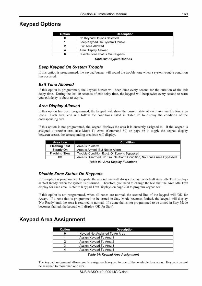
Solution 40 Installation Manual 169
SUB-MASOL40I-0001.IG.C.doc
Keypad Options
Option Description 0 No Keypad Options Selected 1 Beep Keypad On System Trouble 2 Exit Tone Allowed 4 Area Display Allowed 8 Disable Zone Status On Keypads
Table 92: Keypad Options Beep Keypad On System Trouble If this option is programmed, the keypad buzzer will sound the trouble tone when a system trouble condition has occurred. Exit Tone Allowed If this option is programmed, the keypad buzzer will beep once every second for the duration of the exit delay time. During the last 10 seconds of exit delay time, the keypad will beep twice every second to warn you exit delay is about to expire. Area Display Allowed If this option has been programmed, the keypad will show the current state of each area via the four area icons. Each area icon will follow the conditions listed in Table 93 to display the condition of the corresponding area. If this option is not programmed, the keypad displays the area it is currently assigned to. If the keypad is assigned to another area (use Move To Area, (Command 50) on page 66 to toggle the keypad display between areas), the corresponding area icon will display.
Area Icon Condition Flashing Fast Area Is In Alarm
Steady On Area Is Armed, But Not In Alarm Flashing Slow Trouble Condition Exist, Or Zone Is Bypassed
Off Area Is Disarmed, No Trouble/Alarm Condition, No Zones Area Bypassed Table 93: Area Display Functions
Disable Zone Status On Keypads If this option is programmed, keypads, the second line will always display the default Area Idle Text displays as 'Not Ready' when the system is disarmed. Therefore, you need to change the text that the Area Idle Text display for each area. Refer to Keypad Text Displays on page 228 to program keypad text. If this option is not programmed, when all zones are normal, the second line of the keypad will 'OK for Away'. If a zone that is programmed to be armed in Stay Mode becomes faulted, the keypad will display 'Not Ready' until the zone is returned to normal. If a zone that is not programmed to be armed in Stay Mode becomes faulted, the keypad will display 'OK for Stay'.
Keypad Area Assignment
Option Description 0 Keypad Not Assigned To An Area 1 Assign Keypad To Area 1 2 Assign Keypad To Area 2 3 Assign Keypad To Area 3 4 Assign Keypad To Area 4
Table 94: Keypad Area Assignment
The keypad assignment allows you to assign each keypad to one of the available four areas. Keypads cannot be assigned to more than one area.
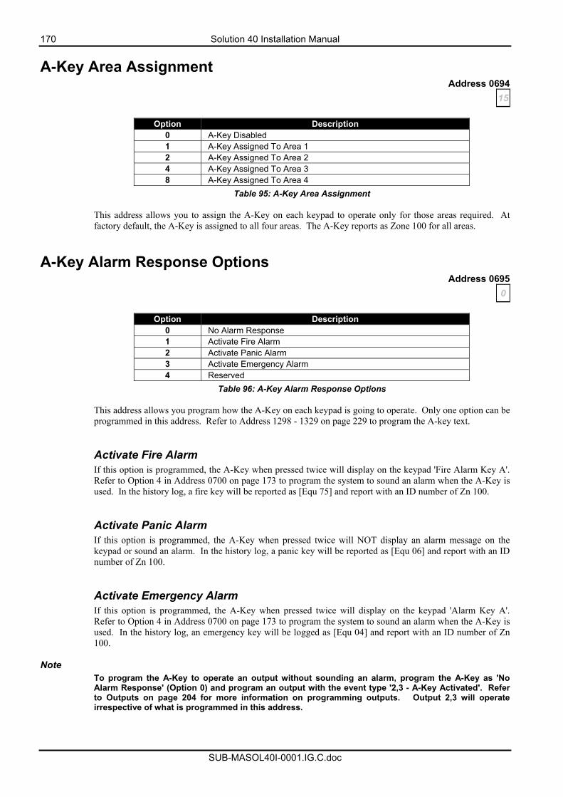
170 Solution 40 Installation Manual
SUB-MASOL40I-0001.IG.C.doc
A-Key Area Assignment Address 0694
15
Option Description 0 A-Key Disabled 1 A-Key Assigned To Area 1 2 A-Key Assigned To Area 2 4 A-Key Assigned To Area 3 8 A-Key Assigned To Area 4
Table 95: A-Key Area Assignment This address allows you to assign the A-Key on each keypad to operate only for those areas required. At factory default, the A-Key is assigned to all four areas. The A-Key reports as Zone 100 for all areas.
A-Key Alarm Response Options Address 0695
0
Option Description 0 No Alarm Response 1 Activate Fire Alarm 2 Activate Panic Alarm 3 Activate Emergency Alarm 4 Reserved
Table 96: A-Key Alarm Response Options
This address allows you program how the A-Key on each keypad is going to operate. Only one option can be programmed in this address. Refer to Address 1298 - 1329 on page 229 to program the A-key text. Activate Fire Alarm If this option is programmed, the A-Key when pressed twice will display on the keypad 'Fire Alarm Key A'. Refer to Option 4 in Address 0700 on page 173 to program the system to sound an alarm when the A-Key is used. In the history log, a fire key will be reported as [Equ 75] and report with an ID number of Zn 100. Activate Panic Alarm If this option is programmed, the A-Key when pressed twice will NOT display an alarm message on the keypad or sound an alarm. In the history log, a panic key will be reported as [Equ 06] and report with an ID number of Zn 100. Activate Emergency Alarm If this option is programmed, the A-Key when pressed twice will display on the keypad 'Alarm Key A'. Refer to Option 4 in Address 0700 on page 173 to program the system to sound an alarm when the A-Key is used. In the history log, an emergency key will be logged as [Equ 04] and report with an ID number of Zn 100.
Note To program the A-Key to operate an output without sounding an alarm, program the A-Key as 'No Alarm Response' (Option 0) and program an output with the event type '2,3 - A-Key Activated'. Refer to Outputs on page 204 for more information on programming outputs. Output 2,3 will operate irrespective of what is programmed in this address.
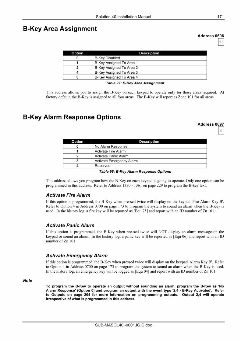
Solution 40 Installation Manual 171
SUB-MASOL40I-0001.IG.C.doc
B-Key Area Assignment Address 0696
15
Option Description 0 B-Key Disabled 1 B-Key Assigned To Area 1 2 B-Key Assigned To Area 2 4 B-Key Assigned To Area 3 8 B-Key Assigned To Area 4
Table 97: B-Key Area Assignment
This address allows you to assign the B-Key on each keypad to operate only for those areas required. At factory default, the B-Key is assigned to all four areas. The B-Key will report as Zone 101 for all areas.
B-Key Alarm Response Options Address 0697
0
Option Description 0 No Alarm Response 1 Activate Fire Alarm 2 Activate Panic Alarm 3 Activate Emergency Alarm 4 Reserved
Table 98: B-Key Alarm Response Options
This address allows you program how the B-Key on each keypad is going to operate. Only one option can be programmed in this address. Refer to Address 1330 - 1361 on page 229 to program the B-key text. Activate Fire Alarm If this option is programmed, the B-Key when pressed twice will display on the keypad 'Fire Alarm Key B'. Refer to Option 4 in Address 0700 on page 173 to program the system to sound an alarm when the B-Key is used. In the history log, a fire key will be reported as [Equ 75] and report with an ID number of Zn 101. Activate Panic Alarm If this option is programmed, the B-Key when pressed twice will NOT display an alarm message on the keypad or sound an alarm. In the history log, a panic key will be reported as [Equ 06] and report with an ID number of Zn 101. Activate Emergency Alarm If this option is programmed, the B-Key when pressed twice will display on the keypad 'Alarm Key B'. Refer to Option 4 in Address 0700 on page 173 to program the system to sound an alarm when the B-Key is used. In the history log, an emergency key will be logged as [Equ 04] and report with an ID number of Zn 101.
Note
To program the B-Key to operate an output without sounding an alarm, program the B-Key as 'No Alarm Response' (Option 0) and program an output with the event type '2,4 - B-Key Activated'. Refer to Outputs on page 204 for more information on programming outputs. Output 2,4 will operate irrespective of what is programmed in this address.
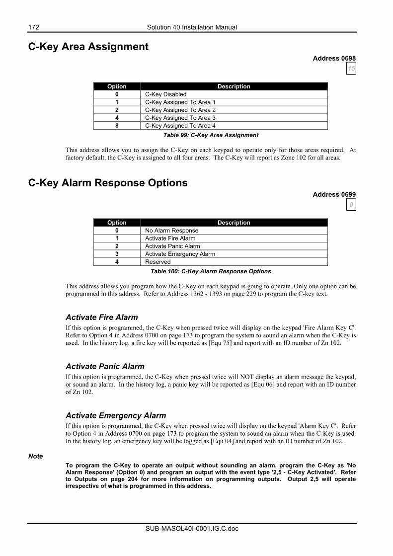
172 Solution 40 Installation Manual
SUB-MASOL40I-0001.IG.C.doc
C-Key Area Assignment Address 0698
15
Option Description 0 C-Key Disabled 1 C-Key Assigned To Area 1 2 C-Key Assigned To Area 2 4 C-Key Assigned To Area 3 8 C-Key Assigned To Area 4
Table 99: C-Key Area Assignment
This address allows you to assign the C-Key on each keypad to operate only for those areas required. At factory default, the C-Key is assigned to all four areas. The C-Key will report as Zone 102 for all areas.
C-Key Alarm Response Options Address 0699
0
Option Description 0 No Alarm Response 1 Activate Fire Alarm 2 Activate Panic Alarm 3 Activate Emergency Alarm 4 Reserved
Table 100: C-Key Alarm Response Options
This address allows you program how the C-Key on each keypad is going to operate. Only one option can be programmed in this address. Refer to Address 1362 - 1393 on page 229 to program the C-key text. Activate Fire Alarm If this option is programmed, the C-Key when pressed twice will display on the keypad 'Fire Alarm Key C'. Refer to Option 4 in Address 0700 on page 173 to program the system to sound an alarm when the C-Key is used. In the history log, a fire key will be reported as [Equ 75] and report with an ID number of Zn 102. Activate Panic Alarm If this option is programmed, the C-Key when pressed twice will NOT display an alarm message the keypad, or sound an alarm. In the history log, a panic key will be reported as [Equ 06] and report with an ID number of Zn 102. Activate Emergency Alarm If this option is programmed, the C-Key when pressed twice will display on the keypad 'Alarm Key C'. Refer to Option 4 in Address 0700 on page 173 to program the system to sound an alarm when the C-Key is used. In the history log, an emergency key will be logged as [Equ 04] and report with an ID number of Zn 102.
Note
To program the C-Key to operate an output without sounding an alarm, program the C-Key as 'No Alarm Response' (Option 0) and program an output with the event type '2,5 - C-Key Activated'. Refer to Outputs on page 204 for more information on programming outputs. Output 2,5 will operate irrespective of what is programmed in this address.
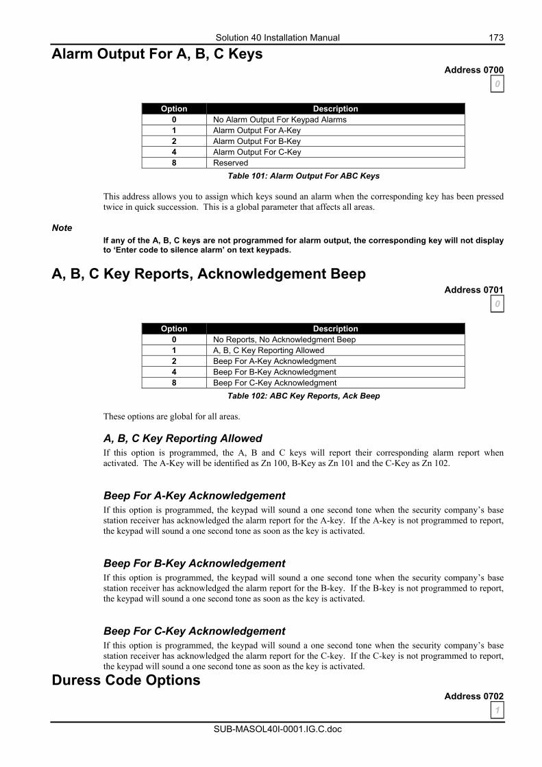
Solution 40 Installation Manual 173
SUB-MASOL40I-0001.IG.C.doc
Alarm Output For A, B, C Keys Address 0700
0
Option Description 0 No Alarm Output For Keypad Alarms 1 Alarm Output For A-Key 2 Alarm Output For B-Key 4 Alarm Output For C-Key 8 Reserved
Table 101: Alarm Output For ABC Keys
This address allows you to assign which keys sound an alarm when the corresponding key has been pressed twice in quick succession. This is a global parameter that affects all areas.
Note If any of the A, B, C keys are not programmed for alarm output, the corresponding key will not display to ‘Enter code to silence alarm’ on text keypads.
A, B, C Key Reports, Acknowledgement Beep Address 0701
0
Option Description 0 No Reports, No Acknowledgment Beep 1 A, B, C Key Reporting Allowed 2 Beep For A-Key Acknowledgment 4 Beep For B-Key Acknowledgment 8 Beep For C-Key Acknowledgment
Table 102: ABC Key Reports, Ack Beep
These options are global for all areas.
A, B, C Key Reporting Allowed If this option is programmed, the A, B and C keys will report their corresponding alarm report when activated. The A-Key will be identified as Zn 100, B-Key as Zn 101 and the C-Key as Zn 102. Beep For A-Key Acknowledgement If this option is programmed, the keypad will sound a one second tone when the security company’s base station receiver has acknowledged the alarm report for the A-key. If the A-key is not programmed to report, the keypad will sound a one second tone as soon as the key is activated.
Beep For B-Key Acknowledgement If this option is programmed, the keypad will sound a one second tone when the security company’s base station receiver has acknowledged the alarm report for the B-key. If the B-key is not programmed to report, the keypad will sound a one second tone as soon as the key is activated. Beep For C-Key Acknowledgement If this option is programmed, the keypad will sound a one second tone when the security company’s base station receiver has acknowledged the alarm report for the C-key. If the C-key is not programmed to report, the keypad will sound a one second tone as soon as the key is activated.
Duress Code Options Address 0702
1
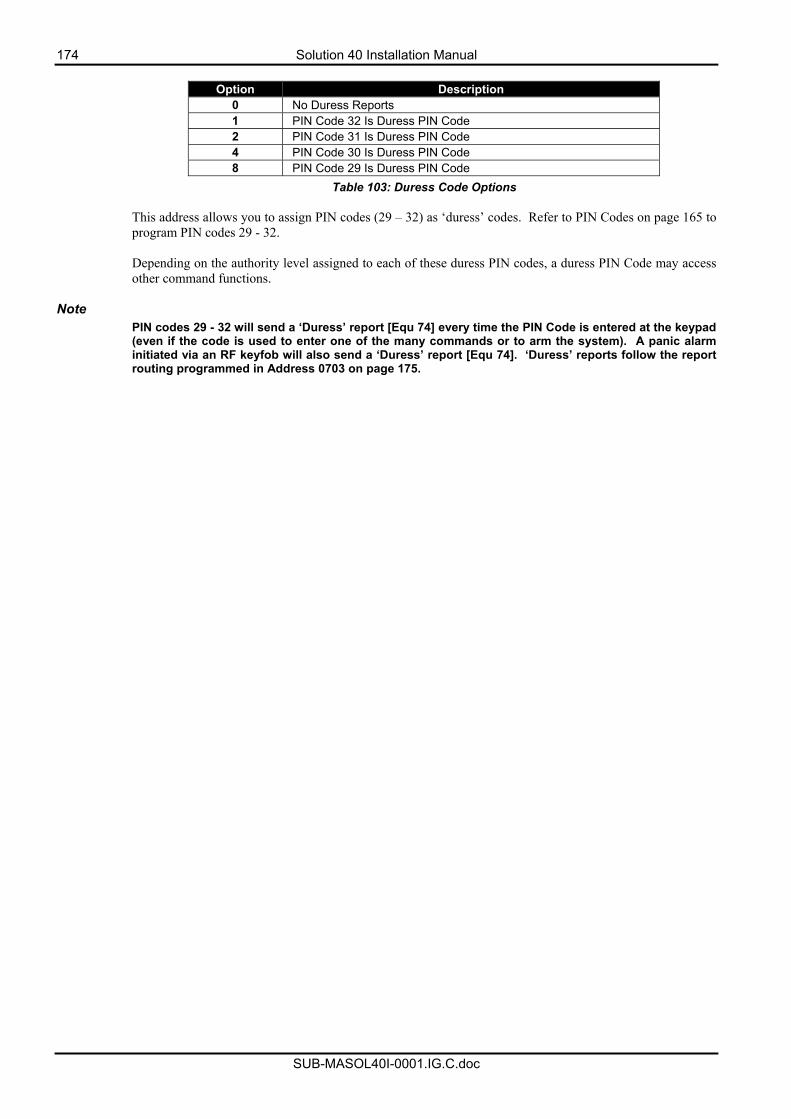
174 Solution 40 Installation Manual
SUB-MASOL40I-0001.IG.C.doc
Option Description
0 No Duress Reports 1 PIN Code 32 Is Duress PIN Code 2 PIN Code 31 Is Duress PIN Code 4 PIN Code 30 Is Duress PIN Code 8 PIN Code 29 Is Duress PIN Code
Table 103: Duress Code Options
This address allows you to assign PIN codes (29 – 32) as ‘duress’ codes. Refer to PIN Codes on page 165 to program PIN codes 29 - 32. Depending on the authority level assigned to each of these duress PIN codes, a duress PIN Code may access other command functions.
Note
PIN codes 29 - 32 will send a ‘Duress’ report [Equ 74] every time the PIN Code is entered at the keypad (even if the code is used to enter one of the many commands or to arm the system). A panic alarm initiated via an RF keyfob will also send a ‘Duress’ report [Equ 74]. ‘Duress’ reports follow the report routing programmed in Address 0703 on page 175.
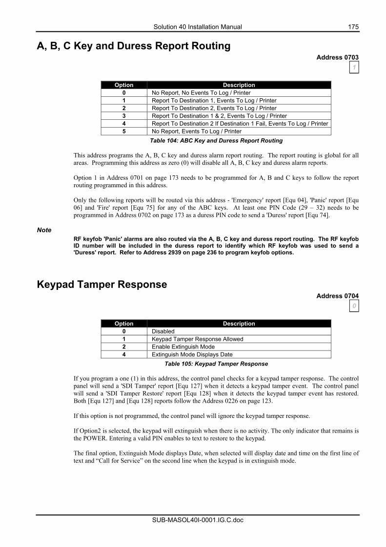
Solution 40 Installation Manual 175
SUB-MASOL40I-0001.IG.C.doc
A, B, C Key and Duress Report Routing Address 0703
1
Option Description 0 No Report, No Events To Log / Printer 1 Report To Destination 1, Events To Log / Printer 2 Report To Destination 2, Events To Log / Printer 3 Report To Destination 1 & 2, Events To Log / Printer 4 Report To Destination 2 If Destination 1 Fail, Events To Log / Printer5 No Report, Events To Log / Printer
Table 104: ABC Key and Duress Report Routing
This address programs the A, B, C key and duress alarm report routing. The report routing is global for all areas. Programming this address as zero (0) will disable all A, B, C key and duress alarm reports. Option 1 in Address 0701 on page 173 needs to be programmed for A, B and C keys to follow the report routing programmed in this address. Only the following reports will be routed via this address - 'Emergency' report [Equ 04], 'Panic' report [Equ 06] and 'Fire' report [Equ 75] for any of the ABC keys. At least one PIN Code (29 – 32) needs to be programmed in Address 0702 on page 173 as a duress PIN code to send a 'Duress' report [Equ 74].
Note RF keyfob 'Panic' alarms are also routed via the A, B, C key and duress report routing. The RF keyfob ID number will be included in the duress report to identify which RF keyfob was used to send a 'Duress' report. Refer to Address 2939 on page 236 to program keyfob options.
Keypad Tamper Response Address 0704
0
Option Description 0 Disabled 1 Keypad Tamper Response Allowed 2 Enable Extinguish Mode 4 Extinguish Mode Displays Date
Table 105: Keypad Tamper Response
If you program a one (1) in this address, the control panel checks for a keypad tamper response. The control panel will send a 'SDI Tamper' report [Equ 127] when it detects a keypad tamper event. The control panel will send a 'SDI Tamper Restore' report [Equ 128] when it detects the keypad tamper event has restored. Both [Equ 127] and [Equ 128] reports follow the Address 0226 on page 123. If this option is not programmed, the control panel will ignore the keypad tamper response. If Option2 is selected, the keypad will extinguish when there is no activity. The only indicator that remains is the POWER. Entering a valid PIN enables to text to restore to the keypad. The final option, Extinguish Mode displays Date, when selected will display date and time on the first line of text and “Call for Service” on the second line when the keypad is in extinguish mode.
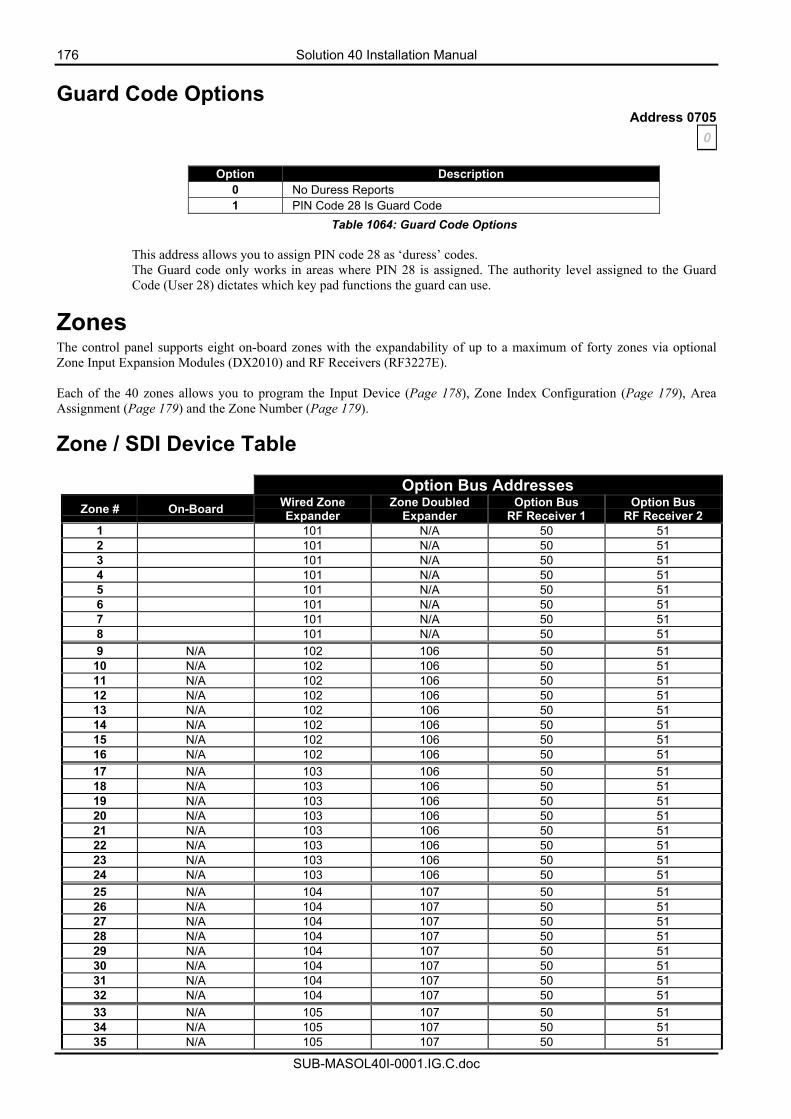
176 Solution 40 Installation Manual
SUB-MASOL40I-0001.IG.C.doc
Guard Code Options Address 0705
0
Option Description 0 No Duress Reports 1 PIN Code 28 Is Guard Code
Table 1064: Guard Code Options
This address allows you to assign PIN code 28 as ‘duress’ codes. The Guard code only works in areas where PIN 28 is assigned. The authority level assigned to the Guard Code (User 28) dictates which key pad functions the guard can use.
Zones The control panel supports eight on-board zones with the expandability of up to a maximum of forty zones via optional Zone Input Expansion Modules (DX2010) and RF Receivers (RF3227E). Each of the 40 zones allows you to program the Input Device (Page 178), Zone Index Configuration (Page 179), Area Assignment (Page 179) and the Zone Number (Page 179).
Zone / SDI Device Table
Option Bus Addresses
Zone # On-Board Wired Zone Expander
Zone Doubled Expander
Option Bus RF Receiver 1
Option Bus RF Receiver 2
1 101 N/A 50 51 2 101 N/A 50 51 3 101 N/A 50 51 4 101 N/A 50 51 5 101 N/A 50 51 6 101 N/A 50 51 7 101 N/A 50 51 8 101 N/A 50 51 9 N/A 102 106 50 51
10 N/A 102 106 50 51 11 N/A 102 106 50 51 12 N/A 102 106 50 51 13 N/A 102 106 50 51 14 N/A 102 106 50 51 15 N/A 102 106 50 51 16 N/A 102 106 50 51 17 N/A 103 106 50 51 18 N/A 103 106 50 51 19 N/A 103 106 50 51 20 N/A 103 106 50 51 21 N/A 103 106 50 51 22 N/A 103 106 50 51 23 N/A 103 106 50 51 24 N/A 103 106 50 51 25 N/A 104 107 50 51 26 N/A 104 107 50 51 27 N/A 104 107 50 51 28 N/A 104 107 50 51 29 N/A 104 107 50 51 30 N/A 104 107 50 51 31 N/A 104 107 50 51 32 N/A 104 107 50 51 33 N/A 105 107 50 51 34 N/A 105 107 50 51 35 N/A 105 107 50 51

Solution 40 Installation Manual 177
SUB-MASOL40I-0001.IG.C.doc
36 N/A 105 107 50 51 37 N/A 105 107 50 51 38 N/A 105 107 50 51 39 N/A 105 107 50 51 40 N/A 105 107 50 51
Table 107: Zone/Option Bus Device Table
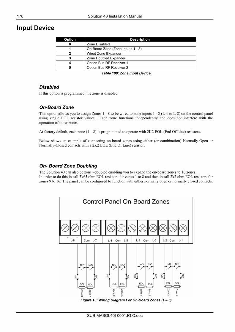
178 Solution 40 Installation Manual
SUB-MASOL40I-0001.IG.C.doc
Input Device
Option Description 0 Zone Disabled 1 On-Board Zone (Zone Inputs 1 - 8) 2 Wired Zone Expander 3 Zone Doubled Expander 4 Option Bus RF Receiver 1 5 Option Bus RF Receiver 2
Table 108: Zone Input Device Disabled If this option is programmed, the zone is disabled. On-Board Zone This option allows you to assign Zones 1 - 8 to be wired to zone inputs 1 - 8 (L-1 to L-8) on the control panel using single EOL resistor values. Each zone functions independently and does not interfere with the operation of other zones. At factory default, each zone (1 – 8) is programmed to operate with 2K2 EOL (End Of Line) resistors. Below shows an example of connecting on-board zones using either (or combination) Normally-Open or Normally-Closed contacts with a 2K2 EOL (End Of Line) resistor. On- Board Zone Doubling The Solution 40 can also be zone –doubled enabling you to expand the on-board zones to 16 zones. In order to do this,install 3k65 ohm EOL resistors for zones 1 to 8 and then install 2k2 ohm EOL resistors for zones 9 to 16. The panel can be configured to function with either normally open or normally closed contacts.
Figure 13: Wiring Diagram For On-Board Zones (1 – 8)
Solution 40 Installation Manual 179
SUB-MASOL40I-0001.IG.C.doc
Wired Zone Expander If this option is programmed, it will assign the zone to a zone expander (DX2010) using a single 2K2 EOL resistor. Refer to page 252 to correctly set up and connect the DX2010 Zone Input Expansion Module. Zone Doubled Expander If you wish to zone double any of the expander boards, 3k65 and 2k2 ohm resistors are required. Zones 9 – 24, the DX2010 must have address set to 106 and Zones 25 – 32, the DX2010 must have the address set to 107. Refer to the section on DX2010 Expander boards for dip switch settings and wiring guides. RF Receiver 1 If this option is programmed, it will assign the zone to RF Receiver 1 (Option Bus Address 50). Option 1 in Address 1249 on page 223 needs to be programmed for RF Receiver 1 to work. To program RF zone devices ID numbers, refer to RF Menu - Adding RF Devices on page 87. RF Receiver 2 If this option is programmed, it will assign the zone to RF Receiver 2 (Option Bus Address 51). Option 2 in Address 1249 on page 223 needs to be programmed for RF Receiver 2 to work. To program RF zone devices ID numbers, refer to RF Menu - Adding RF Devices on page 87.
Zone Index Configuration This address assigns a zone to a zone index. Multiple zones can be assigned to the same zone index. The zone index configures how a group of zones will operate (includes, zone type, pulse count + pulse count time, zone options, alarm and trouble reports and report routing). Up to fifteen (15) different zone indexes can be programmed. Programming the zone index as zero (0) will disable the zone index.
To program zone index group, refer to Zone Index Configuration on page 182 for more information.
Area Assignment This address allows you to assign the zone to an area (Each zone can only be assigned to a single area). Multiple zones can be assigned to the same area. The control panel can be split (partitioned) up to a maximum of four (4) separate areas.
Zone Number This address allows you to program the zone number (01 - 40) that will appear on the keypad display, the control panel's event log, the security company's base station receiver and at the optional printer (if programmed and connected). You may program numerous zones to display as the same zone number on each area (e.g. It is possible to have a Zone 1 for each area).
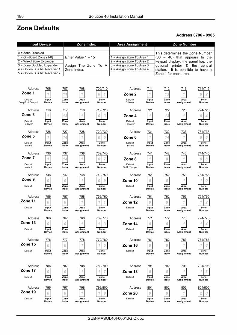
180 Solution 40 Installation Manual
SUB-MASOL40I-0001.IG.C.doc
Zone Defaults Address 0706 - 0905
Input Device Zone Index Area Assignment Zone Number
0 = Zone Disabled 1 = On-Board Zone (1-8) 1 = Assign Zone To Area 1 2 = Wired Zone Expander 2 = Assign Zone To Area 2 3 = Zone Doubled Expander 3 = Assign Zone To Area 3 4 = Option Bus RF Receiver 1 4 = Assign Zone To Area 4 5 = Option Bus RF Receiver 2
Enter Value 1 – 15 Assign The Zone To A Zone Index.
This determines the Zone Number (00 – 40) that appears In the keypad display, the panel log, the optional printer & the central station. It is possible to have a Zone 1 for each area.
Address 706 707 708 709/710 Address 711 712 713 714/715 Zone 1 1 11 1 0 1 Zone 2 1 13 1 0 2
Default Entry/Exit Delay-1
Input Device
Zone Index
Area Assignment
Zone Number
Default Follower
Input Device
Zone Index
Area Assignment
Zone Number
Address 716 717 718 719/720 Address 721 722 723 724/725
Zone 3 1 13 1 0 3 Zone 4 1 13 1 0 4 Default
Follower Input
Device Zone Index
Area Assignment
Zone Number
Default Follower
Input Device
Zone Index
Area Assignment
Zone Number
Address 726 727 728 729/730 Address 731 732 733 734/735
Zone 5 1 14 1 0 5 Zone 6 1 14 1 0 6 Default Instant
Input Device
Zone Index
Area Assignment
Zone Number
Default Instant
Input Device
Zone Index
Area Assignment
Zone Number
Address 736 737 738 739/740 Address 741 742 743 744/745
Zone 7 1 14 1 0 7 Zone 8 1 8 1 0 8 Default Instant
Input Device
Zone Index
Area Assignment
Zone Number
Default 24-Hr Tamper
Input Device
Zone Index
Area Assignment
Zone Number
Address 746 747 748 749/750 Address 751 752 753 754/755
Zone 9 0 0 1 0 9 Zone 10 0 0 1 1 0 Default
Input
Device Zone Index
Area Assignment
Zone Number
Default
Input Device
Zone Index
Area Assignment
Zone Number
Address 756 757 758 759/760 Address 761 762 763 764/765
Zone 11 0 0 1 1 1 Zone 12 0 0 1 1 2 Default
Input
Device Zone Index
Area Assignment
Zone Number
Default
Input Device
Zone Index
Area Assignment
Zone Number
Address 766 767 768 769/770 Address 771 772 773 774/775
Zone 13 0 0 1 1 3 Zone 14 0 0 1 1 4 Default
Input
Device Zone Index
Area Assignment
Zone Number
Default
Input Device
Zone Index
Area Assignment
Zone Number
Address 776 777 778 779/780 Address 781 782 783 784/785
Zone 15 0 0 1 1 5 Zone 16 0 0 1 1 6 Default
Input
Device Zone Index
Area Assignment
Zone Number
Default
Input Device
Zone Index
Area Assignment
Zone Number
Address 786 787 788 789/790 Address 791 792 793 794/795 Zone 17 0 0 1 1 7 Zone 18 0 0 1 1 8
Default
Input Device
Zone Index
Area Assignment
Zone Number
Default
Input Device
Zone Index
Area Assignment
Zone Number
Address 796 797 798 799/800 Address 801 802 803 804/805
Zone 19 0 0 1 1 9 Zone 20 0 0 1 2 0 Default
Input
Device Zone Index
Area Assignment
Zone Number
Default
Input Device
Zone Index
Area Assignment
Zone Number
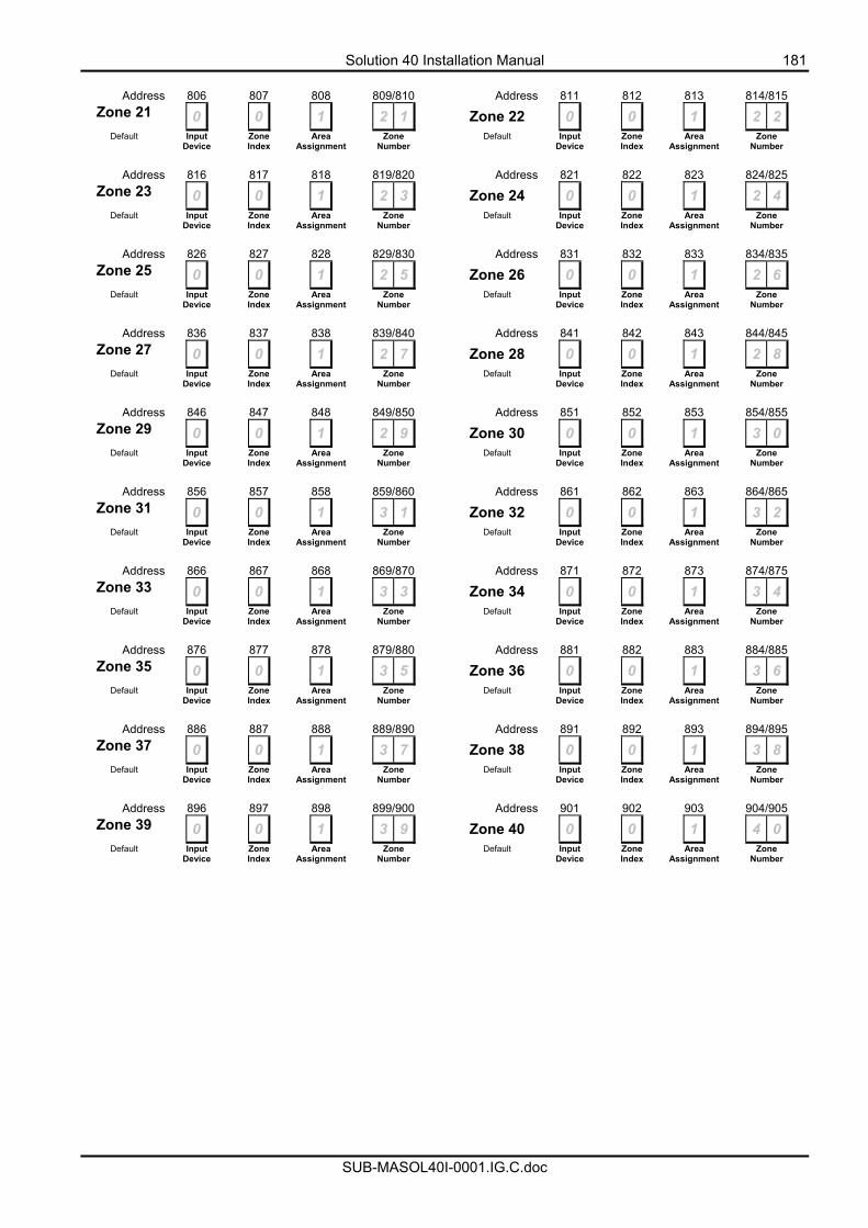
Solution 40 Installation Manual 181
SUB-MASOL40I-0001.IG.C.doc
Address 806 807 808 809/810 Address 811 812 813 814/815
Zone 21 0 0 1 2 1 Zone 22 0 0 1 2 2 Default
Input
Device Zone Index
Area Assignment
Zone Number
Default
Input Device
Zone Index
Area Assignment
Zone Number
Address 816 817 818 819/820 Address 821 822 823 824/825
Zone 23 0 0 1 2 3 Zone 24 0 0 1 2 4 Default
Input
Device Zone Index
Area Assignment
Zone Number
Default
Input Device
Zone Index
Area Assignment
Zone Number
Address 826 827 828 829/830 Address 831 832 833 834/835
Zone 25 0 0 1 2 5 Zone 26 0 0 1 2 6 Default
Input
Device Zone Index
Area Assignment
Zone Number
Default
Input Device
Zone Index
Area Assignment
Zone Number
Address 836 837 838 839/840 Address 841 842 843 844/845
Zone 27 0 0 1 2 7 Zone 28 0 0 1 2 8 Default
Input
Device Zone Index
Area Assignment
Zone Number
Default
Input Device
Zone Index
Area Assignment
Zone Number
Address 846 847 848 849/850 Address 851 852 853 854/855
Zone 29 0 0 1 2 9 Zone 30 0 0 1 3 0 Default
Input
Device Zone Index
Area Assignment
Zone Number
Default
Input Device
Zone Index
Area Assignment
Zone Number
Address 856 857 858 859/860 Address 861 862 863 864/865
Zone 31 0 0 1 3 1 Zone 32 0 0 1 3 2 Default
Input
Device Zone Index
Area Assignment
Zone Number
Default
Input Device
Zone Index
Area Assignment
Zone Number
Address 866 867 868 869/870 Address 871 872 873 874/875
Zone 33 0 0 1 3 3 Zone 34 0 0 1 3 4 Default
Input
Device Zone Index
Area Assignment
Zone Number
Default
Input Device
Zone Index
Area Assignment
Zone Number
Address 876 877 878 879/880 Address 881 882 883 884/885
Zone 35 0 0 1 3 5 Zone 36 0 0 1 3 6 Default
Input
Device Zone Index
Area Assignment
Zone Number
Default
Input Device
Zone Index
Area Assignment
Zone Number
Address 886 887 888 889/890 Address 891 892 893 894/895
Zone 37 0 0 1 3 7 Zone 38 0 0 1 3 8 Default
Input
Device Zone Index
Area Assignment
Zone Number
Default
Input Device
Zone Index
Area Assignment
Zone Number
Address 896 897 898 899/900 Address 901 902 903 904/905
Zone 39 0 0 1 3 9 Zone 40 0 0 1 4 0 Default
Input
Device Zone Index
Area Assignment
Zone Number
Default
Input Device
Zone Index
Area Assignment
Zone Number
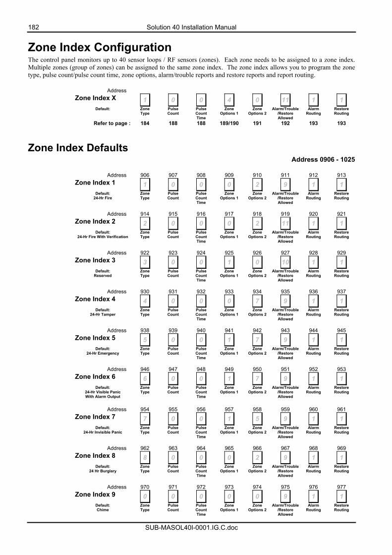
182 Solution 40 Installation Manual
SUB-MASOL40I-0001.IG.C.doc
Zone Index Configuration The control panel monitors up to 40 sensor loops / RF sensors (zones). Each zone needs to be assigned to a zone index. Multiple zones (group of zones) can be assigned to the same zone index. The zone index allows you to program the zone type, pulse count/pulse count time, zone options, alarm/trouble reports and restore reports and report routing. Address Zone Index X 1 0 0 4 0 11 1 1
Default: Zone Type
Pulse Count
Pulse Count Time
Zone Options 1
Zone Options 2
Alarm/Trouble/Restore Allowed
Alarm Routing
Restore Routing
Refer to page : 184 188 188 189/190 191 192 193 193
Zone Index Defaults Address 0906 - 1025
Address 906 907 908 909 910 911 912 913 Zone Index 1 1 0 0 0 2 9 1 1
Default: 24-Hr Fire
Zone Type
Pulse Count
Pulse Count Time
Zone Options 1
Zone Options 2
Alarm/Trouble/Restore Allowed
Alarm Routing
Restore Routing
Address 914 915 916 917 918 919 920 921 Zone Index 2 2 0 0 0 2 11 1 1
Default: 24-Hr Fire With Verification
Zone Type
Pulse Count
Pulse Count Time
Zone Options 1
Zone Options 2
Alarm/Trouble/Restore Allowed
Alarm Routing
Restore Routing
Address 922 923 924 925 926 927 928 929 Zone Index 3 3 0 0 1 0 10 1 1
Default: Reserved
Zone Type
Pulse Count
Pulse Count Time
Zone Options 1
Zone Options 2
Alarm/Trouble/Restore Allowed
Alarm Routing
Restore Routing
Address 930 931 932 933 934 935 936 937 Zone Index 4 4 0 0 0 7 9 1 1
Default: 24-Hr Tamper
Zone Type
Pulse Count
Pulse Count Time
Zone Options 1
Zone Options 2
Alarm/Trouble/Restore Allowed
Alarm Routing
Restore Routing
Address 938 939 940 941 942 943 944 945 Zone Index 5 5 0 0 1 7 9 1 1
Default: 24-Hr Emergency
Zone Type
Pulse Count
Pulse Count Time
Zone Options 1
Zone Options 2
Alarm/Trouble/Restore Allowed
Alarm Routing
Restore Routing
Address 946 947 948 949 950 951 952 953 Zone Index 6 6 0 0 1 7 9 1 1
Default: 24-Hr Visible Panic With Alarm Output
Zone Type
Pulse Count
Pulse Count Time
Zone Options 1
Zone Options 2
Alarm/Trouble/Restore Allowed
Alarm Routing
Restore Routing
Address 954 955 956 957 958 959 960 961 Zone Index 7 7 0 0 1 5 9 1 1
Default: 24-Hr Invisible Panic
Zone Type
Pulse Count
Pulse Count Time
Zone Options 1
Zone Options 2
Alarm/Trouble/Restore Allowed
Alarm Routing
Restore Routing
Address 962 963 964 965 966 967 968 969 Zone Index 8 8 0 0 0 2 9 1 1
Default: 24 Hr Burglary
Zone Type
Pulse Count
Pulse Count Time
Zone Options 1
Zone Options 2
Alarm/Trouble/Restore Allowed
Alarm Routing
Restore Routing
Address 970 971 972 973 974 975 976 977 Zone Index 9 0 0 0 0 0 9 1 1
Default: Chime
Zone Type
Pulse Count
Pulse Count Time
Zone Options 1
Zone Options 2
Alarm/Trouble/Restore Allowed
Alarm Routing
Restore Routing
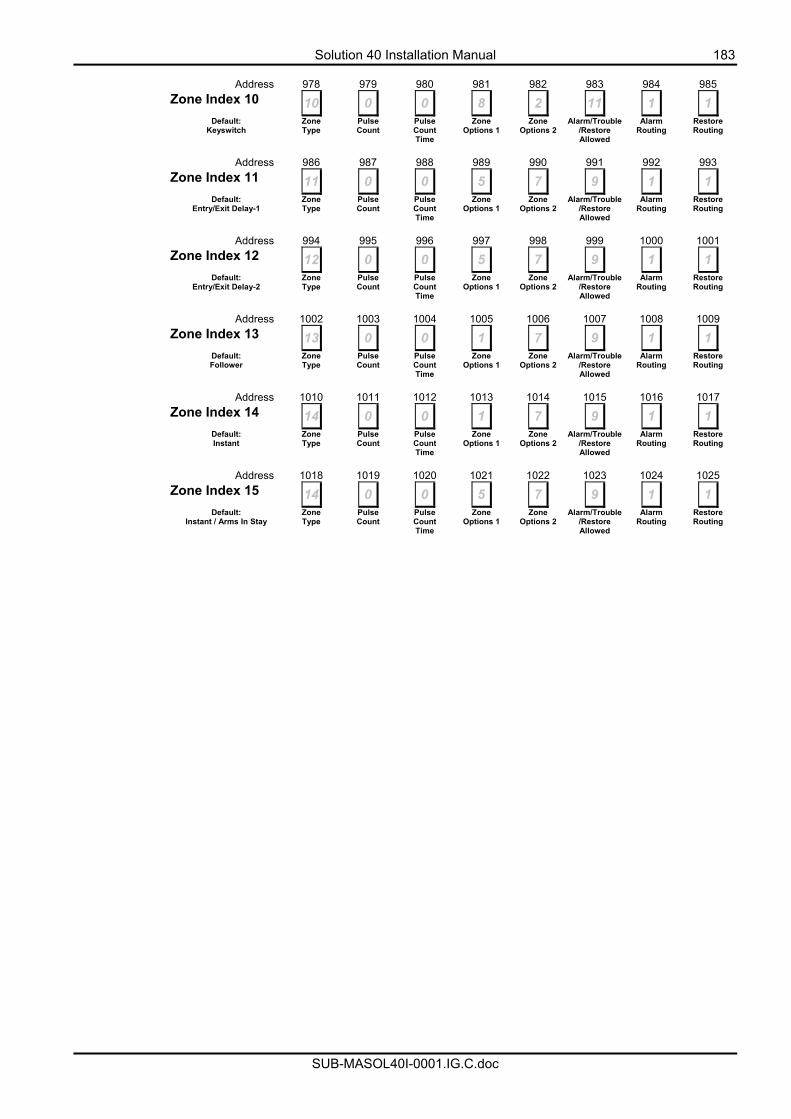
Solution 40 Installation Manual 183
SUB-MASOL40I-0001.IG.C.doc
Address 978 979 980 981 982 983 984 985 Zone Index 10 10 0 0 8 2 11 1 1
Default: Keyswitch
Zone Type
Pulse Count
Pulse Count Time
Zone Options 1
Zone Options 2
Alarm/Trouble/Restore Allowed
Alarm Routing
Restore Routing
Address 986 987 988 989 990 991 992 993 Zone Index 11 11 0 0 5 7 9 1 1
Default: Entry/Exit Delay-1
Zone Type
Pulse Count
Pulse Count Time
Zone Options 1
Zone Options 2
Alarm/Trouble/Restore Allowed
Alarm Routing
Restore Routing
Address 994 995 996 997 998 999 1000 1001 Zone Index 12 12 0 0 5 7 9 1 1
Default: Entry/Exit Delay-2
Zone Type
Pulse Count
Pulse Count Time
Zone Options 1
Zone Options 2
Alarm/Trouble/Restore Allowed
Alarm Routing
Restore Routing
Address 1002 1003 1004 1005 1006 1007 1008 1009 Zone Index 13 13 0 0 1 7 9 1 1
Default: Follower
Zone Type
Pulse Count
Pulse Count Time
Zone Options 1
Zone Options 2
Alarm/Trouble/Restore Allowed
Alarm Routing
Restore Routing
Address 1010 1011 1012 1013 1014 1015 1016 1017 Zone Index 14 14 0 0 1 7 9 1 1
Default: Instant
Zone Type
Pulse Count
Pulse Count Time
Zone Options 1
Zone Options 2
Alarm/Trouble/Restore Allowed
Alarm Routing
Restore Routing
Address 1018 1019 1020 1021 1022 1023 1024 1025 Zone Index 15 14 0 0 5 7 9 1 1
Default: Instant / Arms In Stay
Zone Type
Pulse Count
Pulse Count Time
Zone Options 1
Zone Options 2
Alarm/Trouble/Restore Allowed
Alarm Routing
Restore Routing
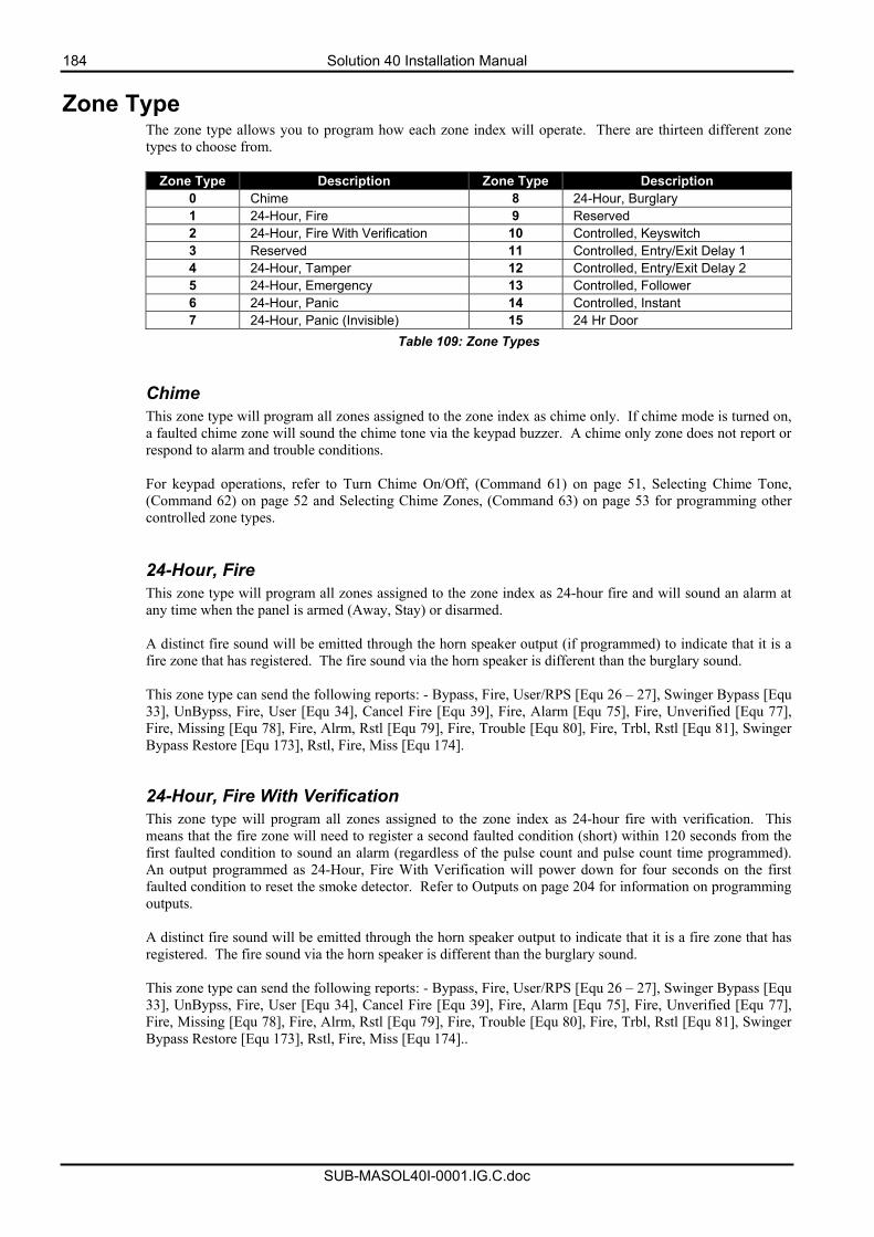
184 Solution 40 Installation Manual
SUB-MASOL40I-0001.IG.C.doc
Zone Type The zone type allows you to program how each zone index will operate. There are thirteen different zone types to choose from.
Zone Type Description Zone Type Description
0 Chime 8 24-Hour, Burglary 1 24-Hour, Fire 9 Reserved 2 24-Hour, Fire With Verification 10 Controlled, Keyswitch 3 Reserved 11 Controlled, Entry/Exit Delay 1 4 24-Hour, Tamper 12 Controlled, Entry/Exit Delay 2 5 24-Hour, Emergency 13 Controlled, Follower 6 24-Hour, Panic 14 Controlled, Instant 7 24-Hour, Panic (Invisible) 15 24 Hr Door
Table 109: Zone Types
Chime This zone type will program all zones assigned to the zone index as chime only. If chime mode is turned on, a faulted chime zone will sound the chime tone via the keypad buzzer. A chime only zone does not report or respond to alarm and trouble conditions. For keypad operations, refer to Turn Chime On/Off, (Command 61) on page 51, Selecting Chime Tone, (Command 62) on page 52 and Selecting Chime Zones, (Command 63) on page 53 for programming other controlled zone types.
24-Hour, Fire This zone type will program all zones assigned to the zone index as 24-hour fire and will sound an alarm at any time when the panel is armed (Away, Stay) or disarmed. A distinct fire sound will be emitted through the horn speaker output (if programmed) to indicate that it is a fire zone that has registered. The fire sound via the horn speaker is different than the burglary sound. This zone type can send the following reports: - Bypass, Fire, User/RPS [Equ 26 – 27], Swinger Bypass [Equ 33], UnBypss, Fire, User [Equ 34], Cancel Fire [Equ 39], Fire, Alarm [Equ 75], Fire, Unverified [Equ 77], Fire, Missing [Equ 78], Fire, Alrm, Rstl [Equ 79], Fire, Trouble [Equ 80], Fire, Trbl, Rstl [Equ 81], Swinger Bypass Restore [Equ 173], Rstl, Fire, Miss [Equ 174].
24-Hour, Fire With Verification This zone type will program all zones assigned to the zone index as 24-hour fire with verification. This means that the fire zone will need to register a second faulted condition (short) within 120 seconds from the first faulted condition to sound an alarm (regardless of the pulse count and pulse count time programmed). An output programmed as 24-Hour, Fire With Verification will power down for four seconds on the first faulted condition to reset the smoke detector. Refer to Outputs on page 204 for information on programming outputs. A distinct fire sound will be emitted through the horn speaker output to indicate that it is a fire zone that has registered. The fire sound via the horn speaker is different than the burglary sound.
This zone type can send the following reports: - Bypass, Fire, User/RPS [Equ 26 – 27], Swinger Bypass [Equ 33], UnBypss, Fire, User [Equ 34], Cancel Fire [Equ 39], Fire, Alarm [Equ 75], Fire, Unverified [Equ 77], Fire, Missing [Equ 78], Fire, Alrm, Rstl [Equ 79], Fire, Trouble [Equ 80], Fire, Trbl, Rstl [Equ 81], Swinger Bypass Restore [Equ 173], Rstl, Fire, Miss [Equ 174]..
Solution 40 Installation Manual 185
SUB-MASOL40I-0001.IG.C.doc
24-Hour, Tamper This zone type is ideal to connect tamper switches from control panel boxes or tamper switches on sensor devices to sound an alarm at any time when the panel is armed (Away, Stay) or disarmed. The control panel will send a ‘Tamper’ report [Equ 3] when this zone type has registered a faulted condition. This zone type can send the following reports: - Tamper [Equ 3], Cross, Tamper [Equ 10], Cross, Unverified [Equ 17], Bypass, 24hr, User/RPS [Equ 30 - 31], Bypass, Swinger [Equ 33], UnBypass, 24hr User [Equ 36], Cancel Alarm [Equ 38], Missing, Trouble [Equ 88], Rstrl, Tamper [Equ 112], Trbl, Tamper [Equ 139], Rstrl, Trbl, Tmpr [Equ 146], Swinger Bypass Restore [Equ 173], Rstrl, Trble, Miss, [Equ 176]. 24-Hour, Emergency This zone type is used for personal emergency alarms (i.e. medical etc). It will sound an alarm at any time if the zone becomes faulted when the panel is armed (Away, Stay) or disarmed. This zone type can send the following reports: - Alarm, Emergency [Equ 4], Cross, Emergency [Equ 11], Cross, Unverified [Equ 17], Bypass, 24hr, User/RPS [Equ 30 - 31], Bypass, Swinger [Equ 33], UnBypass, 24hr User [Equ 36], Cancel Alarm [Equ 38], Missing, Trouble [Equ 88], Rstrl, Emergency [Equ 113], Trbl, Emergency [Equ 140], Rstrl, Trbl, Emerg [Equ 147], Swinger Bypass Restore [Equ 173], Rstrl, Trble, Miss [Equ 176] 24-Hour, Visible Panic This zone type is used for a general type of emergency including the presence of one or more unwanted persons trying to gain entry to the premises. It will sound an alarm at any time when the zone becomes faulted when the panel is armed (Away, Stay), or disarmed. This zone type can send the following: - Alarm, Panic [Equ 5], Cross, Panic [Equ 12], Cross, Unverified [Equ 17], Bypass, 24hr, User/RPS [Equ 30 - 31], Bypass, Swinger [Equ 33], UnBypass, 24hr User [Equ 36], Cancel Alarm [Equ 38], Missing, Trouble [Equ 88], Rstrl, Panic [Equ 114], Trbl, Panic [Equ 141], Rstrl, Trbl, Panic [Equ 148], Swinger Bypass Restore [Equ 173], Rstrl, Trble, Miss [Equ 176].
24-Hour, Invisible Panic This zone type is used for a general type of emergency and is used when there is a presence of one or more unwanted persons trying to gain entry to the premises. When faulted, the zone will not display on the keypad(s) that a panic alarm has occurred or sound any tones at the keypad (even if the alarm output option is programmed). This zone type can send the following reports: - Alarm, Invisible [Equ 6], Cross, Invisible[Equ 13], Cross, Unverified [Equ 17], Bypass, 24hr, User/RPS [Equ 30 - 31], Bypass, Swinger [Equ 33], UnBypass, 24hr User [Equ 36], Cancel Alarm [Equ 38], Missing, Trouble [Equ 88], Rstrl, Invisible [Equ 115], Trbl, Invisible [Equ 142], Rstrl, Trbl, Invis [Equ 149], Swinger Bypass Restore [Equ 173], Rstrl, Trble, Miss [Equ 176]. 24-Hour, Burglary This zone type can sound an alarm at any time when the zone becomes faulted when the panel is armed (Away, Stay) or disarmed. This zone type can send the following reports : - Alarm, 24-hr Burg [Equ 7], Cross, 24-hr Burg [Equ 14], Cross, Unverified [Equ 17], Bypass, 24hr, User/RPS [Equ 30 - 31], Bypass, Swinger [Equ 33], UnBypass, 24hr User [Equ 36], Cancel Alarm [Equ 38], Missing, Alarm [Equ 87], Missing, Trouble [Equ 88], Rstrl, 24-hr Burg [Equ 150], Swinger Bypass Restore [Equ 173], Rstrl, Alarm, Miss [Equ 175], Rstrl, Trble, Miss [Equ 176].
186 Solution 40 Installation Manual
SUB-MASOL40I-0001.IG.C.doc
Controlled, Key-Switch A controlled key-switch allows you to connect momentary or maintained switches to arm the control panel in Away or Stay mode or disarm. The keyswitch will register as PIN Code 255. For maintained switches, connect the EOL (End Of Line) resistor in series with the maintained switch. When the switch becomes open-circuit, it will toggle on or off the arming cycle. A short on the circuit produces an alarm if the area is armed and a trouble condition when the area is disarmed. For momentary switches, connect the EOL (End Of Line) resistor in parallel to the switch. When the switch operates, the switch will short the EOL resistor to toggle on or off the arming cycle. An open circuit produces an alarm when the area is armed and a trouble condition when the area is disarmed. This zone type can send the following reports : - Alarm, Cntrl [Equ 9], Bypass, Cntrl, User/RPS [Equ 28 - 29], Bypass, Forced, Zn [Equ 32], Bypass, Swinger [Equ 33], UnBypass, Cntrl, User [Equ 35], Cancel Alarm [Equ 38], Missing, Alarm [Equ 87], Missing, Trouble [Equ 88], Rstrl, Cntrl [Equ 118], Trbl, Cntrl [Equ 145], Rstrl, Trbl, Cntrl [Equ 152], Swinger Bypass Restore [Equ 173], Rstrl, Alarm, Miss [Equ 175], Rstrl, Trble, Miss [Equ 176]. Controlled Entry/Exit Delay 1 This zone type allows you to enter the premises and disarm the system before sounding an alarm. If you fail to disarm the system before the entry delay time has expired, an alarm will occur (Refer to Address 0264 - 0265 on page 142 to program the entry time). A controlled entry/exit delay zone will not sound an alarm during the disarmed state (Off). This zone type can send the following reports : - Alarm, Cntrl, Dly [Equ 8], Cross, Cntrl, Dly [Equ 15], Cross, Unverified [Equ 17], Bypass, Cntrl, User/RPS [Equ 28 - 29], Bypass, Forced, Zn [Equ 32], Bypass, Swinger [Equ 33], UnBypass, Cntrl, User [Equ 35], Cancel Alarm [Equ 38], Missing, Alarm [Equ 87], Missing, Trouble [Equ 88], Rstrl, Cntrl, Dly [Equ 117], Trbl, Cntrl, Dly [Equ 144], Rstrl, Trbl, Dly [Equ 151], Swinger Bypass Restore [Equ 173], Rstrl, Alarm, Miss [Equ 175], Rstrl, Trble, Miss [Equ 176]. Controlled Entry/Exit Delay 2 This zone type allows you to enter the premises and disarm the system before sounding an alarm. If you fail to disarm the system before the entry delay time has expired, an alarm will occur (Refer to Address 0266 - 0267 on page 143 to program the entry time). A controlled entry/exit delay zone will not sound an alarm during the disarmed state (Off). This zone type can send the following reports : - Alarm, Cntrl, Dly [Equ 8], Cross, Cntrl, Dly [Equ 15], Cross, Unverified [Equ 17], Bypass, Cntrl, User/RPS [Equ 28 - 29], Bypass, Forced, Zn [Equ 32], Bypass, Swinger [Equ 33], UnBypass, Cntrl, User [Equ 35], Cancel Alarm [Equ 38], Missing, Alarm [Equ 87], Missing, Trouble [Equ 88], Rstrl, Cntrl, Dly [Equ 117], Trbl, Cntrl, Dly [Equ 144], Rstrl, Trbl, Dly [Equ 151], Swinger Bypass Restore [Equ 173], Rstrl, Alarm, Miss [Equ 175], Rstrl, Trble, Miss [Equ 176]. Controlled, Follower A controlled follower zone will not sound an alarm during the disarmed state (Off). A controlled follower zone will operate as a controlled instant zone if it becomes faulted during the armed state if it is not faulted during the delay time of a controlled entry/exit delay zone. This zone type can send the following reports: - Alarm, Cntrl, Dly [Equ 9], Cross, Cntrl [Equ 16], Cross, Unverified [Equ 17], Bypass, Cntrl, User/RPS [Equ 28 - 29], Bypass, Forced, Zn [Equ 32], Bypass, Swinger [Equ 33], UnBypass, Cntrl, User [Equ 35], Cancel Alarm [Equ 38], Missing, Alarm [Equ 87], Missing, Trouble [Equ 88], Rstrl, Cntrl [Equ 118], Trbl, Cntrl [Equ 145], Rstrl, Trbl [Equ 152], Swinger Bypass Restore [Equ 173], Rstrl, Alarm, Miss [Equ 175], Rstrl, Trble, Miss [Equ 176].
Solution 40 Installation Manual 187
SUB-MASOL40I-0001.IG.C.doc
Controlled, Instant A controlled instant zone will sound an alarm during the armed state (Away, Stay) as soon as it becomes faulted. A controlled instant zone will not register or sound an alarm during the disarmed state. This zone type can send the following reports: - Alarm, Cntrl, Dly [Equ 9], Cross, Cntrl [Equ 16], Cross, Unverified [Equ 17], Bypass, Cntrl, User/RPS [Equ 28 - 29], Bypass, Forced, Zn [Equ 32], Bypass, Swinger [Equ 33], UnBypass, Cntrl, User [Equ 35], Cancel Alarm [Equ 38], Missing, Alarm [Equ 87], Missing, Trouble [Equ 88], Rstrl, Cntrl [Equ 118], Trbl, Cntrl [Equ 145], Rstrl, Trbl [Equ 152], Swinger Bypass Restore [Equ 173], Rstrl, Alarm, Miss [Equ 175], Rstrl, Trble, Miss [Equ 176]. 24-Hour Door When this zone function is assigned to a zone in an area that is armed, the zone functions the same as an Instant zone. When the area is disarmed, the zone function becomes a 24hr function. If faulted zones are programmed to report a trouble, a trouble will be reported as soon as the zone is in the trouble condition. The zone, if not set up to send troubles, will create an alarm condition. When the zone is faulted, a timer starts. If the zone remains faulted for the programmed time, the zone creates an alarm. If the zone restores before the programmed time, then no alarm condition is created. Zone pulse counts and count time can be applied to this zone type. This zone type can send the following reports: - Alarm, 24hr Burg [Equ 7], Rstrl, 24hr Burg [Equ 116], Trbl, 24hr Burg [Equ 143], Rstrl, Trbl, 24hr Burg [Equ 150].
RF Transmitters and Zone States With the exception of the door / window transmitter, all RF transmitters show only two electrical states.(Normal and Faulted) Note: The Door / Window transmitter RF3401E has the ability to monitor both a reed switch (magnet) and a supervised sensor loop. After the ID for the door/window transmitter is added, the control panel shows the status for the zone as normal. If the first message from the transmitter is “no magnet and open loop”, the control panel reports the zone as faulted. If a “normal magnet” message is received, the loop is supervised. Cut out the reed switch if not used.
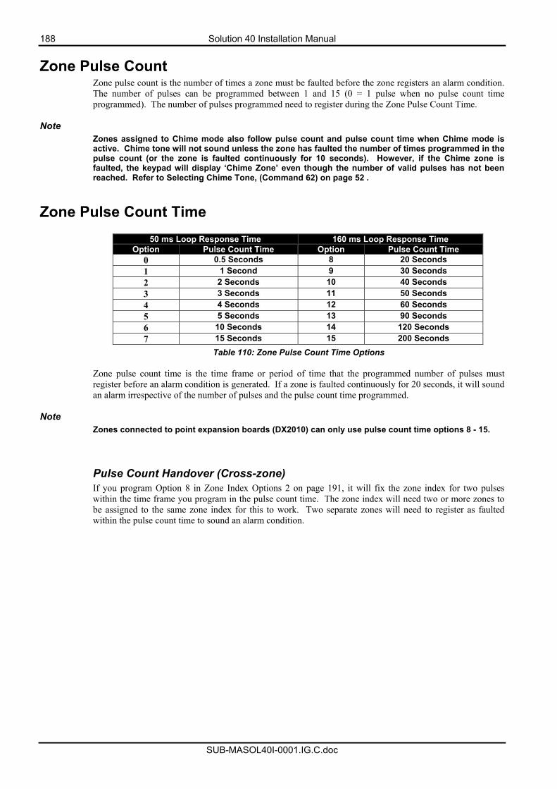
188 Solution 40 Installation Manual
SUB-MASOL40I-0001.IG.C.doc
Zone Pulse Count Zone pulse count is the number of times a zone must be faulted before the zone registers an alarm condition. The number of pulses can be programmed between 1 and 15 (0 = 1 pulse when no pulse count time programmed). The number of pulses programmed need to register during the Zone Pulse Count Time.
Note Zones assigned to Chime mode also follow pulse count and pulse count time when Chime mode is active. Chime tone will not sound unless the zone has faulted the number of times programmed in the pulse count (or the zone is faulted continuously for 10 seconds). However, if the Chime zone is faulted, the keypad will display ‘Chime Zone’ even though the number of valid pulses has not been reached. Refer to Selecting Chime Tone, (Command 62) on page 52 .
Zone Pulse Count Time
50 ms Loop Response Time 160 ms Loop Response Time Option Pulse Count Time Option Pulse Count Time
0 0.5 Seconds 8 20 Seconds 1 1 Second 9 30 Seconds 2 2 Seconds 10 40 Seconds 3 3 Seconds 11 50 Seconds 4 4 Seconds 12 60 Seconds 5 5 Seconds 13 90 Seconds 6 10 Seconds 14 120 Seconds 7 15 Seconds 15 200 Seconds
Table 110: Zone Pulse Count Time Options Zone pulse count time is the time frame or period of time that the programmed number of pulses must register before an alarm condition is generated. If a zone is faulted continuously for 20 seconds, it will sound an alarm irrespective of the number of pulses and the pulse count time programmed.
Note Zones connected to point expansion boards (DX2010) can only use pulse count time options 8 - 15. Pulse Count Handover (Cross-zone) If you program Option 8 in Zone Index Options 2 on page 191, it will fix the zone index for two pulses within the time frame you program in the pulse count time. The zone index will need two or more zones to be assigned to the same zone index for this to work. Two separate zones will need to register as faulted within the pulse count time to sound an alarm condition.
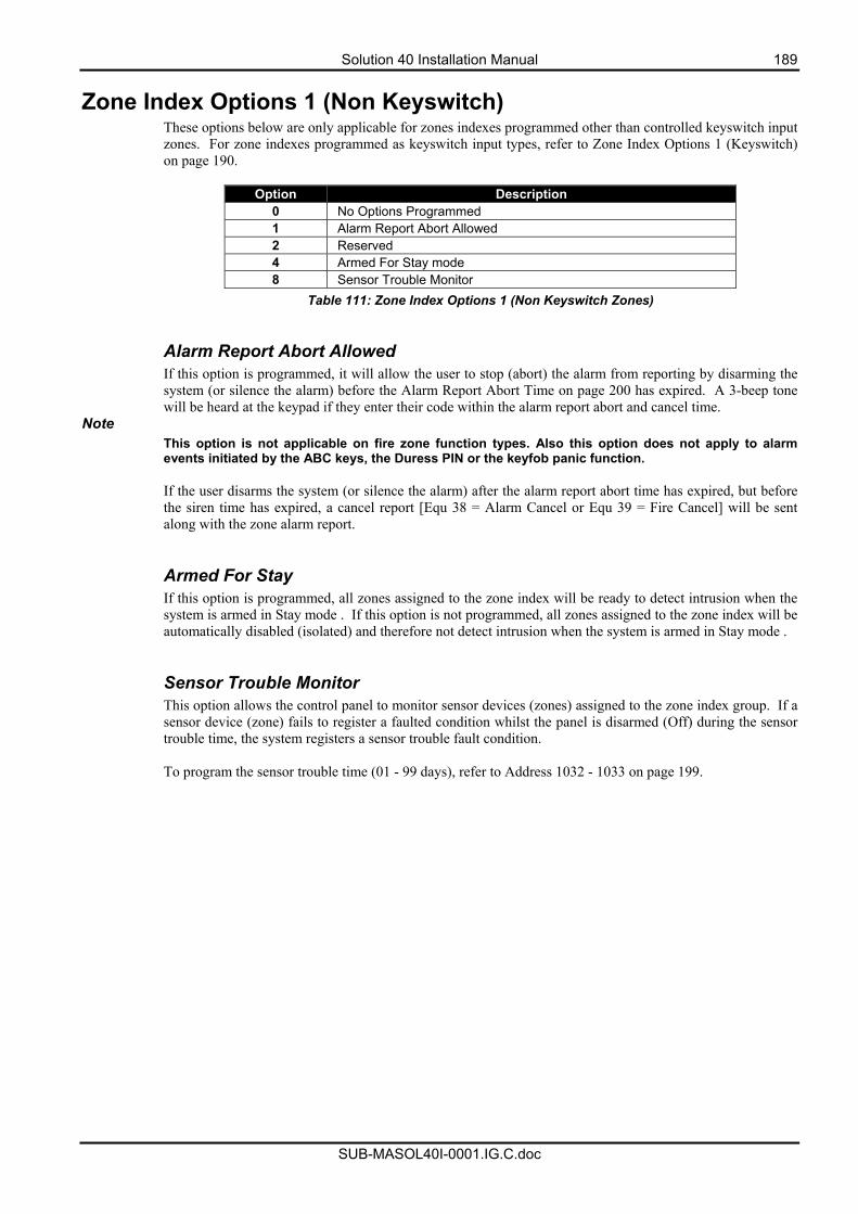
Solution 40 Installation Manual 189
SUB-MASOL40I-0001.IG.C.doc
Zone Index Options 1 (Non Keyswitch) These options below are only applicable for zones indexes programmed other than controlled keyswitch input zones. For zone indexes programmed as keyswitch input types, refer to Zone Index Options 1 (Keyswitch) on page 190.
Option Description
0 No Options Programmed 1 Alarm Report Abort Allowed 2 Reserved 4 Armed For Stay mode 8 Sensor Trouble Monitor
Table 111: Zone Index Options 1 (Non Keyswitch Zones) Alarm Report Abort Allowed If this option is programmed, it will allow the user to stop (abort) the alarm from reporting by disarming the system (or silence the alarm) before the Alarm Report Abort Time on page 200 has expired. A 3-beep tone will be heard at the keypad if they enter their code within the alarm report abort and cancel time.
Note This option is not applicable on fire zone function types. Also this option does not apply to alarm events initiated by the ABC keys, the Duress PIN or the keyfob panic function. If the user disarms the system (or silence the alarm) after the alarm report abort time has expired, but before the siren time has expired, a cancel report [Equ 38 = Alarm Cancel or Equ 39 = Fire Cancel] will be sent along with the zone alarm report. Armed For Stay If this option is programmed, all zones assigned to the zone index will be ready to detect intrusion when the system is armed in Stay mode . If this option is not programmed, all zones assigned to the zone index will be automatically disabled (isolated) and therefore not detect intrusion when the system is armed in Stay mode . Sensor Trouble Monitor This option allows the control panel to monitor sensor devices (zones) assigned to the zone index group. If a sensor device (zone) fails to register a faulted condition whilst the panel is disarmed (Off) during the sensor trouble time, the system registers a sensor trouble fault condition. To program the sensor trouble time (01 - 99 days), refer to Address 1032 - 1033 on page 199.
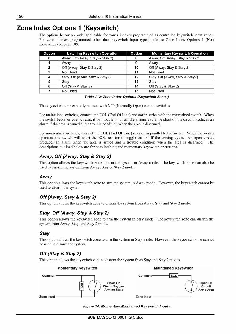
190 Solution 40 Installation Manual
SUB-MASOL40I-0001.IG.C.doc
Zone Index Options 1 (Keyswitch) The options below are only applicable for zones indexes programmed as controlled keyswitch input zones. For zone indexes programmed other than keyswitch input types, refer to Zone Index Options 1 (Non Keyswitch) on page 189.
Option Latching Keyswitch Operation Option Momentary Keyswitch Operation
0 Away, Off (Away, Stay & Stay 2) 8 Away, Off (Away, Stay & Stay 2) 1 Away 9 Away 2 Off (Away, Stay & Stay 2) 10 Off (Away, Stay & Stay 2) 3 Not Used 11 Not Used 4 Stay, Off (Away, Stay & Stay2) 12 Stay, Off (Away, Stay & Stay2) 5 Stay 13 Stay 6 Off (Stay & Stay 2) 14 Off (Stay & Stay 2) 7 Not Used 15 Not Used
Table 112: Zone Index Options (Keyswitch Zones) The keyswitch zone can only be used with N/O (Normally Open) contact switches. For maintained switches, connect the EOL (End Of Line) resistor in series with the maintained switch. When the switch becomes open-circuit, it will toggle on or off the arming cycle. A short on the circuit produces an alarm if the area is armed and a trouble condition when the area is disarmed. For momentary switches, connect the EOL (End Of Line) resistor in parallel to the switch. When the switch operates, the switch will short the EOL resistor to toggle on or off the arming cycle. An open circuit produces an alarm when the area is armed and a trouble condition when the area is disarmed. The descriptions outlined below are for both latching and momentary keyswitch operations. Away, Off (Away, Stay & Stay 2) This option allows the keyswitch zone to arm the system in Away mode. The keyswitch zone can also be used to disarm the system from Away, Stay or Stay 2 mode. Away This option allows the keyswitch zone to arm the system in Away mode. However, the keyswitch cannot be used to disarm the system. Off (Away, Stay & Stay 2) This option allows the keyswitch zone to disarm the system from Away, Stay and Stay 2 mode. Stay, Off (Away, Stay & Stay 2) This option allows the keyswitch zone to arm the system in Stay mode. The keyswitch zone can disarm the system from Away, Stay and Stay 2 mode. Stay This option allows the keyswitch zone to arm the system in Stay mode. However, the keyswitch zone cannot be used to disarm the system. Off (Stay & Stay 2) This option allows the keyswitch zone to disarm the system from Stay and Stay 2 modes.
Figure 14: Momentary/Maintained Keyswitch Inputs
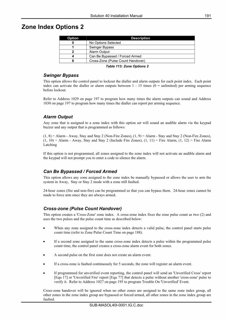
Solution 40 Installation Manual 191
SUB-MASOL40I-0001.IG.C.doc
Zone Index Options 2
Option Description 0 No Options Selected 1 Swinger Bypass 2 Alarm Output 4 Can Be Bypassed / Forced Armed 8 Cross-Zone (Pulse Count Handover)
Table 113: Zone Options 2 Swinger Bypass This option allows the control panel to lockout the dialler and alarm outputs for each point index. Each point index can activate the dialler or alarm outputs between 1 - 15 times (0 = unlimited) per arming sequence before lockout. Refer to Address 1029 on page 197 to program how many times the alarm outputs can sound and Address 1030 on page 197 to program how many times the dialler can report per arming sequence.
Alarm Output Any zone that is assigned to a zone index with this option set will sound an audible alarm via the keypad buzzer and any output that is programmed as follows: (1, 8) = Alarm - Away, Stay and Stay 2 (Non-Fire Zones), (1, 9) = Alarm - Stay and Stay 2 (Non-Fire Zones), (1, 10) = Alarm - Away, Stay and Stay 2 (Include Fire Zones), (1, 11) = Fire Alarm, (1, 12) = Fire Alarm Latching If this option is not programmed, all zones assigned to the zone index will not activate an audible alarm and the keypad will not prompt you to enter a code to silence the alarm. Can Be Bypassed / Forced Armed This option allows any zone assigned to the zone index be manually bypassed or allows the user to arm the system in Away, Stay or Stay 2 mode with a zone still faulted. 24-hour zones (fire and non-fire) can be programmed so that you can bypass them. 24-hour zones cannot be made to force arm since they are always armed. Cross-zone (Pulse Count Handover) This option creates a 'Cross-Zone' zone index. A cross-zone index fixes the zone pulse count as two (2) and uses the two pulses and the pulse count time as described below: • When any zone assigned to the cross-zone index detects a valid pulse, the control panel starts pulse
count time (refer to Zone Pulse Count Time on page 188).
• If a second zone assigned to the same cross-zone index detects a pulse within the programmed pulse count time, the control panel creates a cross-zone alarm event for both zones.
• A second pulse on the first zone does not create an alarm event.
• If a cross-zone is faulted continuously for 5 seconds, the zone will register an alarm event.
• If programmed for unverified event reporting, the control panel will send an 'Unverified Cross' report
[Equ 17] or 'Unverified Fire' report [Equ 77] that detects a pulse without another 'cross-zone' pulse to verify it. Refer to Address 1027 on page 195 to program Trouble On 'Unverified' Event.
Cross-zone handover will be ignored when no other zones are assigned to the same zone index group, all other zones in the zone index group are bypassed or forced armed, all other zones in the zone index group are faulted.
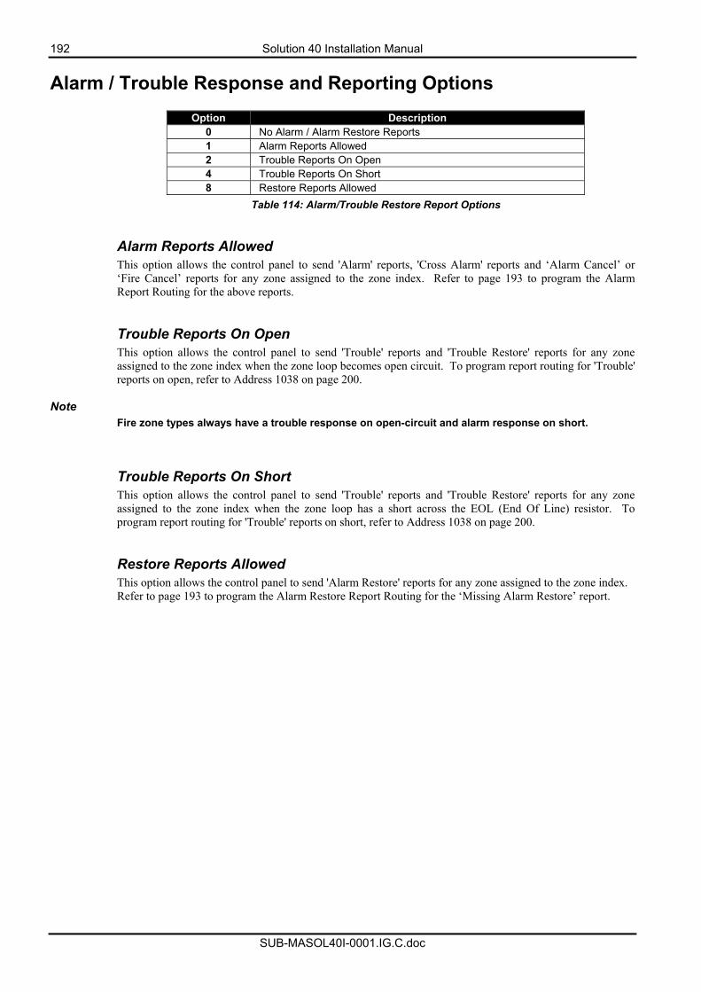
192 Solution 40 Installation Manual
SUB-MASOL40I-0001.IG.C.doc
Alarm / Trouble Response and Reporting Options
Option Description 0 No Alarm / Alarm Restore Reports 1 Alarm Reports Allowed 2 Trouble Reports On Open 4 Trouble Reports On Short 8 Restore Reports Allowed
Table 114: Alarm/Trouble Restore Report Options
Alarm Reports Allowed This option allows the control panel to send 'Alarm' reports, 'Cross Alarm' reports and ‘Alarm Cancel’ or ‘Fire Cancel’ reports for any zone assigned to the zone index. Refer to page 193 to program the Alarm Report Routing for the above reports. Trouble Reports On Open This option allows the control panel to send 'Trouble' reports and 'Trouble Restore' reports for any zone assigned to the zone index when the zone loop becomes open circuit. To program report routing for 'Trouble' reports on open, refer to Address 1038 on page 200.
Note Fire zone types always have a trouble response on open-circuit and alarm response on short. Trouble Reports On Short This option allows the control panel to send 'Trouble' reports and 'Trouble Restore' reports for any zone assigned to the zone index when the zone loop has a short across the EOL (End Of Line) resistor. To program report routing for 'Trouble' reports on short, refer to Address 1038 on page 200. Restore Reports Allowed This option allows the control panel to send 'Alarm Restore' reports for any zone assigned to the zone index. Refer to page 193 to program the Alarm Restore Report Routing for the ‘Missing Alarm Restore’ report.
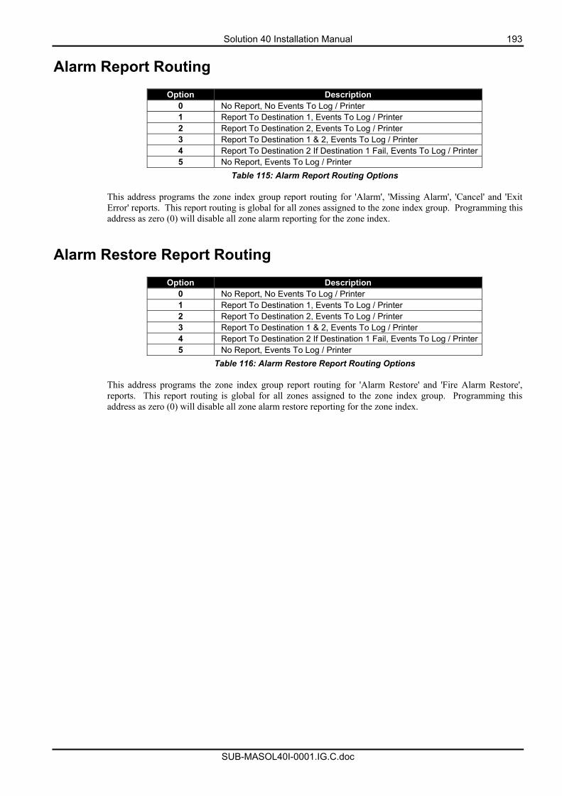
Solution 40 Installation Manual 193
SUB-MASOL40I-0001.IG.C.doc
Alarm Report Routing
Option Description 0 No Report, No Events To Log / Printer 1 Report To Destination 1, Events To Log / Printer 2 Report To Destination 2, Events To Log / Printer 3 Report To Destination 1 & 2, Events To Log / Printer 4 Report To Destination 2 If Destination 1 Fail, Events To Log / Printer5 No Report, Events To Log / Printer
Table 115: Alarm Report Routing Options
This address programs the zone index group report routing for 'Alarm', 'Missing Alarm', 'Cancel' and 'Exit Error' reports. This report routing is global for all zones assigned to the zone index group. Programming this address as zero (0) will disable all zone alarm reporting for the zone index.
Alarm Restore Report Routing
Option Description 0 No Report, No Events To Log / Printer 1 Report To Destination 1, Events To Log / Printer 2 Report To Destination 2, Events To Log / Printer 3 Report To Destination 1 & 2, Events To Log / Printer 4 Report To Destination 2 If Destination 1 Fail, Events To Log / Printer5 No Report, Events To Log / Printer
Table 116: Alarm Restore Report Routing Options
This address programs the zone index group report routing for 'Alarm Restore' and 'Fire Alarm Restore', reports. This report routing is global for all zones assigned to the zone index group. Programming this address as zero (0) will disable all zone alarm restore reporting for the zone index.
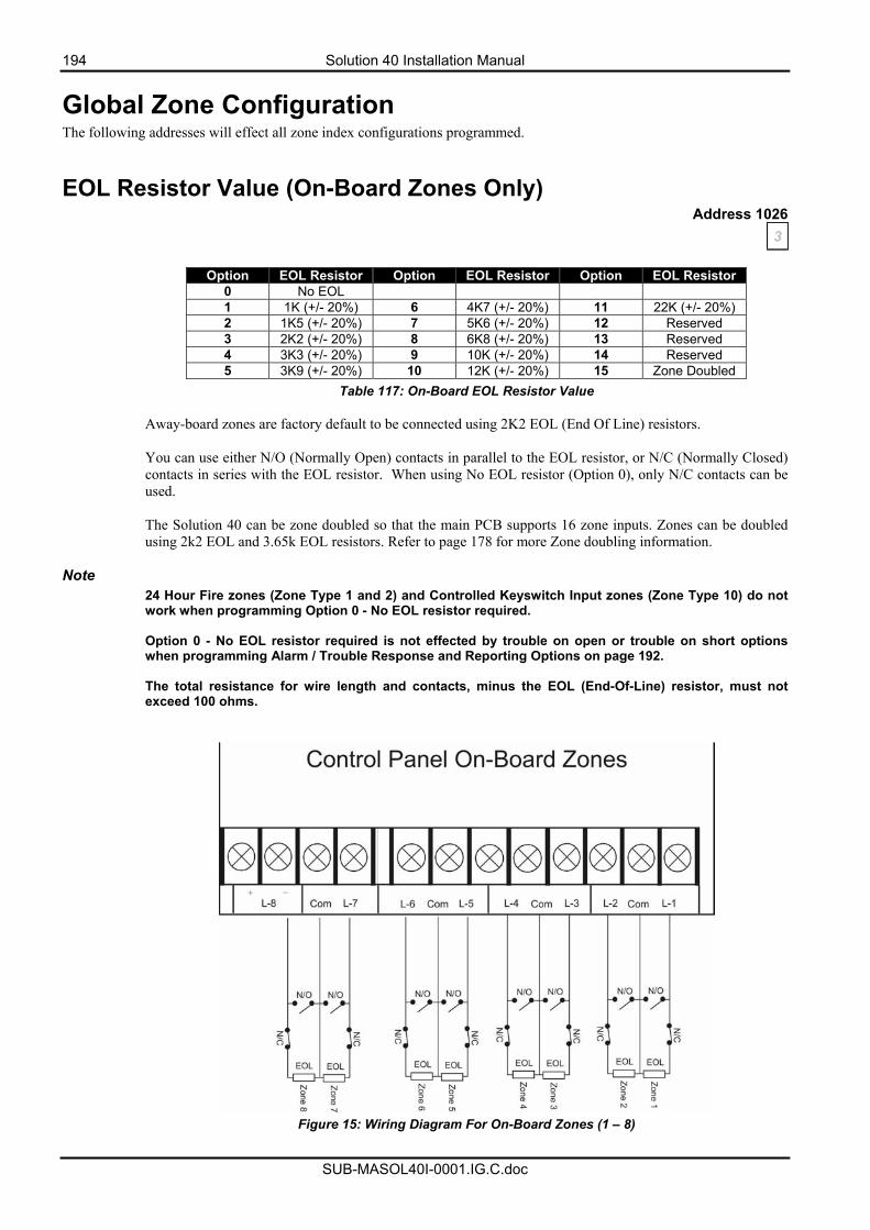
194 Solution 40 Installation Manual
SUB-MASOL40I-0001.IG.C.doc
Global Zone Configuration The following addresses will effect all zone index configurations programmed.
EOL Resistor Value (On-Board Zones Only) Address 1026
3
Option EOL Resistor Option EOL Resistor Option EOL Resistor 0 No EOL 1 1K (+/- 20%) 6 4K7 (+/- 20%) 11 22K (+/- 20%) 2 1K5 (+/- 20%) 7 5K6 (+/- 20%) 12 Reserved 3 2K2 (+/- 20%) 8 6K8 (+/- 20%) 13 Reserved 4 3K3 (+/- 20%) 9 10K (+/- 20%) 14 Reserved 5 3K9 (+/- 20%) 10 12K (+/- 20%) 15 Zone Doubled
Table 117: On-Board EOL Resistor Value Away-board zones are factory default to be connected using 2K2 EOL (End Of Line) resistors. You can use either N/O (Normally Open) contacts in parallel to the EOL resistor, or N/C (Normally Closed) contacts in series with the EOL resistor. When using No EOL resistor (Option 0), only N/C contacts can be used. The Solution 40 can be zone doubled so that the main PCB supports 16 zone inputs. Zones can be doubled using 2k2 EOL and 3.65k EOL resistors. Refer to page 178 for more Zone doubling information.
Note
24 Hour Fire zones (Zone Type 1 and 2) and Controlled Keyswitch Input zones (Zone Type 10) do not work when programming Option 0 - No EOL resistor required. Option 0 - No EOL resistor required is not effected by trouble on open or trouble on short options when programming Alarm / Trouble Response and Reporting Options on page 192. The total resistance for wire length and contacts, minus the EOL (End-Of-Line) resistor, must not exceed 100 ohms.
Figure 15: Wiring Diagram For On-Board Zones (1 – 8)
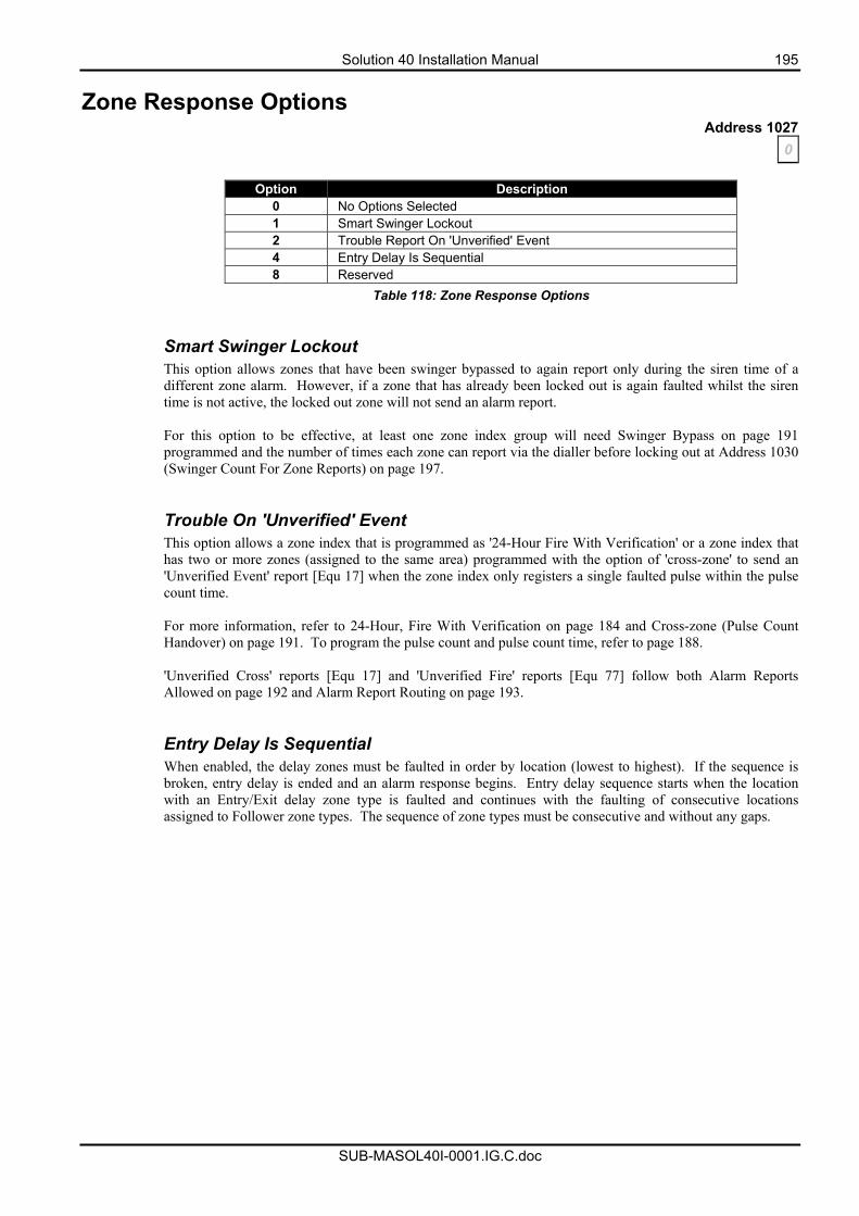
Solution 40 Installation Manual 195
SUB-MASOL40I-0001.IG.C.doc
Zone Response Options Address 1027
0
Option Description 0 No Options Selected 1 Smart Swinger Lockout 2 Trouble Report On 'Unverified' Event 4 Entry Delay Is Sequential 8 Reserved
Table 118: Zone Response Options Smart Swinger Lockout This option allows zones that have been swinger bypassed to again report only during the siren time of a different zone alarm. However, if a zone that has already been locked out is again faulted whilst the siren time is not active, the locked out zone will not send an alarm report. For this option to be effective, at least one zone index group will need Swinger Bypass on page 191 programmed and the number of times each zone can report via the dialler before locking out at Address 1030 (Swinger Count For Zone Reports) on page 197. Trouble On 'Unverified' Event This option allows a zone index that is programmed as '24-Hour Fire With Verification' or a zone index that has two or more zones (assigned to the same area) programmed with the option of 'cross-zone' to send an 'Unverified Event' report [Equ 17] when the zone index only registers a single faulted pulse within the pulse count time. For more information, refer to 24-Hour, Fire With Verification on page 184 and Cross-zone (Pulse Count Handover) on page 191. To program the pulse count and pulse count time, refer to page 188. 'Unverified Cross' reports [Equ 17] and 'Unverified Fire' reports [Equ 77] follow both Alarm Reports Allowed on page 192 and Alarm Report Routing on page 193. Entry Delay Is Sequential When enabled, the delay zones must be faulted in order by location (lowest to highest). If the sequence is broken, entry delay is ended and an alarm response begins. Entry delay sequence starts when the location with an Entry/Exit delay zone type is faulted and continues with the faulting of consecutive locations assigned to Follower zone types. The sequence of zone types must be consecutive and without any gaps.

196 Solution 40 Installation Manual
SUB-MASOL40I-0001.IG.C.doc
Bypass/Force Bypass Report Routing Address 1028
1
Option Description 0 No Report, No Events To Log / Printer 1 Report To Destination 1, Events To Log / Printer 2 Report To Destination 2, Events To Log / Printer 3 Report To Destination 1 & 2, Events To Log / Printer 4 Report To Destination 2 If Destination 1 Fail, Events To Log / Printer 5 No Report, Events To Log / Printer
Table 119: Bypass/Force Bypass Report Routing Options
This address programs the zone bypass and forced zone bypass report routing. This report routing is global for all areas programmed when the system is partitioned into multiple areas. Programming this address as zero (0) will disable all zone bypass and forced zone bypass reports. The report routing for bypass reports require Option 1 - Zone Bypass, Swinger Bypass Reports Allowed and for bypass restore reports require Option 2 - Zone Bypass, Swinger Bypass Restore Reports Allowed on page 198 programmed. To program/restrict the number of zones that can be bypassed or forced armed, you will need to program the Zone Bypass / Force Arm Limit on page 139. Only zones that are assigned to a zone index group with the option Can Be Bypassed / Forced Armed on page 191 programmed can send ‘bypass’ or ‘bypass restore’ reports. A ‘Swinger Bypass’ report or ‘Swinger Bypass Restore’ report can only be sent if one or more zones are assigned to a zone index group with the option Swinger Bypass on page 191 programmed. To bypass zones, refer to Bypassing Zones on page 34.
Solution 40 Installation Manual 197
SUB-MASOL40I-0001.IG.C.doc
Swinger Count For Alarm Output Address 1029
1 Each individual zone has a swinger count for alarm output. 'Swinger Bypass' reports are not sent for swinger bypass for alarm output. 'Swinger Bypass' reports have their own swinger count (see next parameter). The swinger count is reset on both arming and disarming of the system, allowing the swinger bypass feature to work for both controlled and 24-hour zones.
Example Assume the swinger bypass option is enabled, the panel is armed, no zones are in alarm and the swinger count for alarm output is set to 2, Zones 1, 3 and 5 go into alarm. At the end of siren time, the swinger count for alarm output for zones 1, 3 and 5 decrement from 2 to 1. Since the counter does not reach zero, no zones are bypassed. A second alarm event for any of those zones bypasses that zone.
Note When the Swinger Count is set to zero (0), zones with swinger bypass enabled are bypassed on one activation. Swinger Count for alarm output is required for SIA control panel standard for false alarm reduction.
Swinger Count For Zone Reports Address 1030
2 Swinger shutdown for the dialler is global for each zone index programmed with the option Swinger Bypass on page 191. Every time the system is armed (in Away, Stay or Stay 2 mode) and disarmed, the swinger count for zone reports is reset.
Example Assume the system is armed in Away or Stay mode and there are no alarms. When the zone sends an 'Alarm' or 'Trouble' report, the swinger count for zone reports is checked. If the counter is zero (0), the zone is bypassed from reporting and a 'Swinger Bypass' report [Equ 33] is sent. If the counter is not zero (0), the swinger count will decrement by one (1) and an 'Alarm' or 'Trouble' report will be sent. If you program Option 1 - Smart Swinger Lockout on page 195 in Address 1027, zones that have become swinger bypassed can again report if faulted during the active siren time of another faulted zone.
Note If a zone is locked out from reporting (swinger bypassed), the system no longer registers the zone in the system log (Command 85) or registers a sensor Chime trouble condition until the swinger count has been reset or smart swinger lockout takes effect. Refer to Smart Swinger Lockout on page 195 for more information. Both 'Alarm' and 'Trouble' reports follow the swinger count.
198 Solution 40 Installation Manual
SUB-MASOL40I-0001.IG.C.doc
Bypass, Swinger Bypass, Sensor Monitor Report Options Address 1031
3
Option Description 0 No Bypass, Sensor Trouble Reports and Restore Reports Allowed 1 Zone Bypass, Swinger Bypass Reports Allowed 2 Zone Bypass, Swinger Bypass Restore Reports Allowed 4 Sensor Trouble Reports Allowed 8 Sensor Trouble Restore Reports Allowed
Table 120: Bypass, Swinger Bypass, and Sensor Monitor Report Options Zone Bypass, Swinger Bypass Reports Allowed This option allows the system to send the following reports: • 'Bypass' reports for all zones that you manually bypass using the Bypass command (see page 34), or
bypass via the RPS Upload/Download software. • 'Forced Bypass' reports for all zones that are faulted when you arm the system in Away or Stay mode. • 'Swinger Bypass' reports for all zones that have become locked out from reporting again. Only zones assigned to a zone index that has the option 'Can Be Bypassed / Forced Armed' programmed on page 191 can be bypassed or forced armed. To program the bypass/forced arm limit, refer to page 139. For a zone index group to send a 'Swinger Bypass' report [Equ 33], you will need to program Zone Index Options 2 on page 191 as swinger bypass and also program the Swinger Count For Zone Reports on page 197. The swinger count for zone reports programs the number of times each zone can send alarm and/or trouble reports per arming sequence before locking out. These reports follow the Bypass/Force Bypass Report Routing on page 196. Zone Bypass, Swinger Bypass Restore Reports Allowed This option allows the system to send the following restore reports: • 'Bypass Restore' reports for zones that you manually un-bypass using the Bypass command (see page
34), or bypass via the RPS Upload/Download software. • 'Forced Bypass Restore' reports for zones that have restored after you have armed the system in Away
or Stay mode. • 'Swinger Bypass Restore' reports for zones when you arm the system or when you disarm it. These reports follow the Bypass/Force Bypass Report Routing on page 196.
Note To program/restrict the number of zones that can be bypassed or forced armed, you will need to program the Zone Bypass / Force Arm Limit on page 139. Only zones that are assigned to a zone index group with the option Can Be Bypassed / Forced Armed on page 191 programmed can send ‘bypass’ or ‘bypass restore’ reports.
Solution 40 Installation Manual 199
SUB-MASOL40I-0001.IG.C.doc
Sensor Trouble Reports Allowed This option allows the system to send the following trouble reports. [Equ 121] - RF Battery Low, [Equ 123] - RF Tamper Trouble, [Equ 133] - Sensor Monitor Trouble. These reports follow the Zone Trouble Report / Restore Report Routing on page 200. The 'Sensor Monitor Trouble' report [Equ 133] needs Sensor Trouble Monitor on page 189 programmed for any zone index group that requires this report to be sent. Sensor Trouble Restore Reports Allowed This option allows the system to send the following trouble reports. [Equ 122] - RF Battery Low Restore, [Equ 124] - RF Tamper Trouble Restore, [Equ 134] - Sensor Monitor Trouble Restore. These reports follow the Zone Trouble Report / Restore Report Routing on page 200. The 'Sensor Monitor Trouble Restore' report [Equ 134] needs Sensor Trouble Monitor on page 189 programmed for any zone index group that requires this report to be sent.
Sensor Monitor Time Address 1032 - 1033
0 7
Address Description 1032 Increments Of Days (Tens Digit) 1033 Increments Of Days (Units Digit)
Table 121: Sensor Monitor Time
These addresses program how many days (00 – 99) a sensor device (zone) can remain sealed before registering as a faulty device (trouble condition). The sensor monitor time is only active when the area is disarmed (off). When the area is armed (Away or Stay), the sensor monitor time is not active (pauses). The sensor monitor time will continue when the area is next disarmed. Only zones assigned to a zone index group that has Sensor Trouble Monitor on page 189 programmed will be monitored by the control panel. Refer to page 199 to program Option 4 - Sensor Trouble Reports Allowed and Option 8 - Sensor Trouble Restore Reports Allowed. These two reports follow the Zone Trouble Report / Restore Report Routing on page 200.
200 Solution 40 Installation Manual
SUB-MASOL40I-0001.IG.C.doc
Alarm Report Abort Time Address 1034
2
Option Alarm Report Abort Time 0 & 1 15 Seconds
2 30 Seconds 3 - 15 45 Seconds
Table 122: Alarm Report Abort Time These addresses program how many seconds the control panel will delay reporting the pending zone alarm report. If you enter your PIN code during this delay time, the control panel will abort the zone alarm report (Non-Fire zones only). If you do not enter your PIN code within the delay time programmed, the alarm report will be sent. If you enter your PIN Code after the alarm report abort time has expired, but before the siren timer has expired, the system will send a 'Cancel' report. Only zones assigned to a zone index group that has Alarm Report Abort Allowed on page 189 programmed can have their alarm reports aborted or send a cancel report.
Note The 'Cancel Alarm' report [Equ 38] and 'Cancel Fire' report [Equ 39] can be disabled by programming Address 0234 on page 126 as zero.
Zone Trouble Report / Restore Report Routing Address 1038
1
Option Description 0 No Report, No Events To Log / Printer 1 Report To Destination 1, Events To Log / Printer 2 Report To Destination 2, Events To Log / Printer 3 Report To Destination 1 & 2, Events To Log / Printer 4 Report To Destination 2 If Destination 1 Fail, Events To Log / Printer 5 No Report, Events To Log / Printer
Table 123: Zone Trouble Report/Restore Report Routing Options
This address programs the report routing for zone trouble and zone trouble restore reports. This report routing is global for all areas. Programming This address as zero (0) will disable the following reports: - Fire, Missing [Equ 78], Fire, Trouble [Equ 80], Fire, Trouble Restore [Equ 81], Missing Trouble [Equ 88], RF Battery Low [Equ 121], RF Battery Restore [Equ 122], RF Tamper Trouble [Equ 123], RF Tamper Restore [Equ 124], Sensor Monitor Trouble [Equ 133], Sensor Monitor Restore [Equ 134], Trouble, Tamper [Equ 139], Trouble, Emergency [Equ 140], Trouble, Panic (Visible) [Equ 141], Trouble, Panic (Invisible) [Equ 142], Trouble, 24-Hr Burg [Equ 143], Trouble, Delay [Equ 144], Trouble, Follower, Instant, K/S [Equ 145], Trouble Restore, Tamper [Equ 146], Trouble Restore, Emergency [Equ 147], Trouble Restore, Panic (Visible) [Equ 148], Trouble Restore, Panic (Invisible) [Equ 149], Trouble Restore, 24-Hr Burg [Equ 150], Trouble Restore, Delay [Equ 151], Trouble Restore, Follower, Instant, K/S [Equ 152], Fire, Missing Restore (Log Only) [Equ 174], Trouble, Missing Restore (Log Only) [Equ 176].
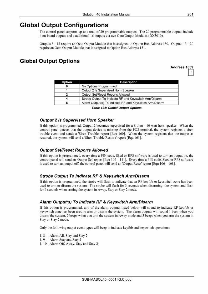
Solution 40 Installation Manual 201
SUB-MASOL40I-0001.IG.C.doc
Global Output Configurations The control panel supports up to a total of 20 programmable outputs. The 20 programmable outputs include 4 on-board outputs and a additional 16 outputs via two Octo Output Modules (DX3010). Outputs 5 - 12 require an Octo Output Module that is assigned to Option Bus Address 150. Outputs 13 - 20 require an Octo Output Module that is assigned to Option Bus Address 151.
Global Output Options Address 1039
1
Option Description 0 No Options Programmed 1 Output 2 Is Supervised Horn Speaker 2 Output Set/Reset Reports Allowed 4 Strobe Output To Indicate RF and Keyswitch Arm/Disarm 8 Alarm Output(s) To Indicate RF and Keyswitch Arm/Disarm
Table 124: Global Output Options
Output 2 Is Supervised Horn Speaker If this option is programmed, Output 2 becomes supervised for a 8 ohm - 10 watt horn speaker. When the control panel detects that the output device is missing from the PO2 terminal, the system registers a siren trouble event and sends a 'Siren Trouble' report [Equ 160]. When the system registers that the output as restored, the system will send a 'Siren Trouble Restore' report [Equ 161]. Output Set/Reset Reports Allowed If this option is programmed, every time a PIN code, Sked or RPS software is used to turn an output on, the control panel will send an 'Output Set' report [Equ 109 – 111]. Every time a PIN code, Sked or RPS software is used to turn an output off, the control panel will send an 'Output Reset' report [Equ 106 – 108]. Strobe Output To Indicate RF & Keyswitch Arm/Disarm If this option is programmed, the strobe will flash to indicate that an RF keyfob or keyswitch zone has been used to arm or disarm the system. The strobe will flash for 3 seconds when disarming the system and flash for 6 seconds when arming the system in Away, Stay or Stay 2 mode. Alarm Output(s) To Indicate RF & Keyswitch Arm/Disarm If this option is programmed, any of the alarm outputs listed below will sound to indicate RF keyfob or keyswitch zone has been used to arm or disarm the system. The alarm outputs will sound 1 beep when you disarm the system, 2 beeps when you arm the system in Away mode and 3 beeps when you arm the system in Stay or Stay 2 mode. Only the following output event types will beep to indicate keyfob and keyswitch operations: 1, 8 - Alarm All, Stay and Stay 2 1, 9 - Alarm Stay and Stay 2 1, 10 - Alarm Off, Away, Stay and Stay 2
202 Solution 40 Installation Manual
SUB-MASOL40I-0001.IG.C.doc
Siren Time Address 1040
5 Siren time programs how long alarm outputs will sound when the control panel detects an alarm condition. Address 1040 is programmed in increments of 1 minute. You can program siren time as zero (0) – disabled or between one (1) minute and fifteen (15) minutes (Factory default is 5 minutes). The following outputs will operate as soon as siren time starts: 1, 5 - Siren Time 1, 9 - Alarm In Stay or Stay 2 1, 7 – Silent Alarm 1, 10 - Alarm In Off, Away, Stay or Stay 2 1, 8 - Alarm In Away, Stay or Stay 2 1, 11 - Fire Alarm
Note Siren time starts as soon as a zone becomes faulted and registers an alarm condition. Therefore, when you delay alarm to sound until reports have been sent (Address 0221 on page 120), the alarm outputs will not sound for the full duration of the siren time programmed.
Horn Speaker Frequency Address 1041
2 This address is only applicable when Output 2 (PO2) is configured as a supervised horn speaker output. Refer to Option 1 - Output 2 Is Supervised Horn Speaker on page 201 for more information. This parameter sets the warble frequency for the alarm output functions (1-8, 1-9, 1-10). The setting chosen here does not apply to other output functions. This address allows you to program the frequency rate that the horn speaker will sound during an alarm. Programming the sound rate as zero is the slowest frequency, whilst programming a fifteen is the fastest frequency. This will allow you to determine which alarm system is sounding the horn speaker when two or more installations are close to each other (each alarm system can sound at a different frequency).
Note This address does not change the frequency rate when sounding a fire alarm tone.
Horn Speaker Beep Volume Address 1042
7 This address is only applicable when Output 2 (PO2) is configured as a supervised horn/speaker output. Refer to Option 1 - Output 2 Is Supervised Horn Speaker on page 201 for more information. This address allows you to program the volume of indication beeps (0 = No Beeps / 15 = Highest Volume) that will be heard when you arm and disarm the system via RF keyfobs or keyswitch zones. Refer to Option 8 - Alarm Output(s) To Indicate RF & Keyswitch Arm/Disarm on page 201 to program alarm outputs to beep when you remotely arm and disarm the system.
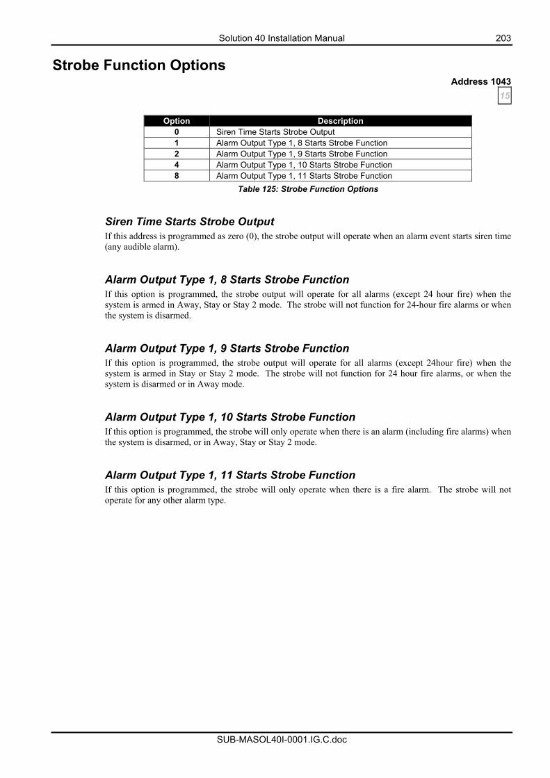
Solution 40 Installation Manual 203
SUB-MASOL40I-0001.IG.C.doc
Strobe Function Options Address 1043
15
Option Description 0 Siren Time Starts Strobe Output 1 Alarm Output Type 1, 8 Starts Strobe Function 2 Alarm Output Type 1, 9 Starts Strobe Function 4 Alarm Output Type 1, 10 Starts Strobe Function 8 Alarm Output Type 1, 11 Starts Strobe Function
Table 125: Strobe Function Options
Siren Time Starts Strobe Output If this address is programmed as zero (0), the strobe output will operate when an alarm event starts siren time (any audible alarm). Alarm Output Type 1, 8 Starts Strobe Function If this option is programmed, the strobe output will operate for all alarms (except 24 hour fire) when the system is armed in Away, Stay or Stay 2 mode. The strobe will not function for 24-hour fire alarms or when the system is disarmed. Alarm Output Type 1, 9 Starts Strobe Function If this option is programmed, the strobe output will operate for all alarms (except 24hour fire) when the system is armed in Stay or Stay 2 mode. The strobe will not function for 24 hour fire alarms, or when the system is disarmed or in Away mode. Alarm Output Type 1, 10 Starts Strobe Function If this option is programmed, the strobe will only operate when there is an alarm (including fire alarms) when the system is disarmed, or in Away, Stay or Stay 2 mode. Alarm Output Type 1, 11 Starts Strobe Function If this option is programmed, the strobe will only operate when there is a fire alarm. The strobe will not operate for any other alarm type.
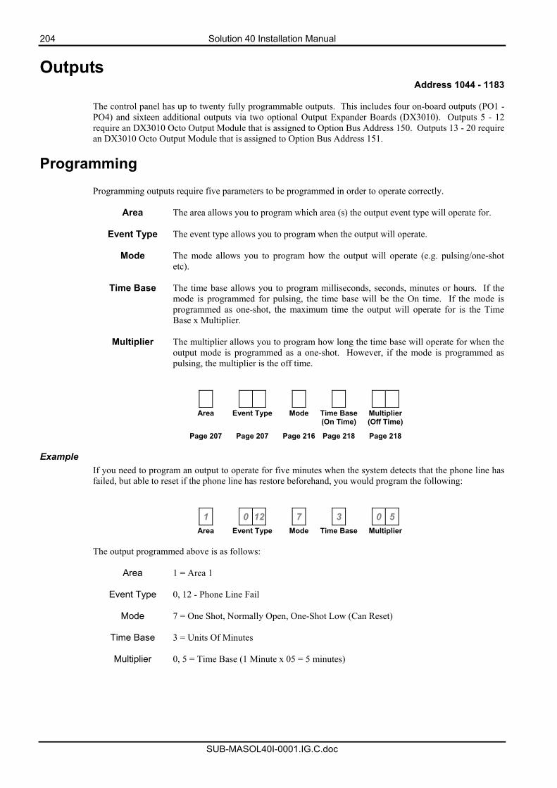
204 Solution 40 Installation Manual
SUB-MASOL40I-0001.IG.C.doc
Outputs Address 1044 - 1183
The control panel has up to twenty fully programmable outputs. This includes four on-board outputs (PO1 - PO4) and sixteen additional outputs via two optional Output Expander Boards (DX3010). Outputs 5 - 12 require an DX3010 Octo Output Module that is assigned to Option Bus Address 150. Outputs 13 - 20 require an DX3010 Octo Output Module that is assigned to Option Bus Address 151.
Programming Programming outputs require five parameters to be programmed in order to operate correctly.
Area The area allows you to program which area (s) the output event type will operate for.
Event Type The event type allows you to program when the output will operate.
Mode The mode allows you to program how the output will operate (e.g. pulsing/one-shot etc).
Time Base The time base allows you to program milliseconds, seconds, minutes or hours. If the
mode is programmed for pulsing, the time base will be the On time. If the mode isprogrammed as one-shot, the maximum time the output will operate for is the Time Base x Multiplier.
Multiplier The multiplier allows you to program how long the time base will operate for when the
output mode is programmed as a one-shot. However, if the mode is programmed as pulsing, the multiplier is the off time.
Area Event Type Mode Time Base(On Time)
Multiplier (Off Time)
Page 207 Page 207 Page 216 Page 218 Page 218 Example
If you need to program an output to operate for five minutes when the system detects that the phone line has failed, but able to reset if the phone line has restore beforehand, you would program the following:
1 0 12 7 3 0 5
Area Event Type Mode Time Base Multiplier
The output programmed above is as follows:
Area 1 = Area 1
Event Type 0, 12 - Phone Line Fail
Mode 7 = One Shot, Normally Open, One-Shot Low (Can Reset)
Time Base 3 = Units Of Minutes
Multiplier 0, 5 = Time Base (1 Minute x 05 = 5 minutes)
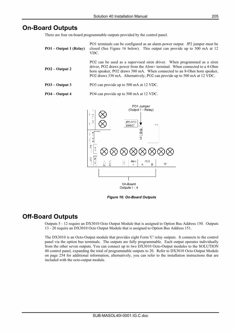
Solution 40 Installation Manual 205
SUB-MASOL40I-0001.IG.C.doc
On-Board Outputs There are four on-board programmable outputs provided by the control panel.
PO1 – Output 1 (Relay) PO1 terminals can be configured as an alarm power output. JP2 jumper must be closed (See Figure 16 below). This output can provide up to 500 mA at 12 VDC.
PO2 – Output 2
PO2 can be used as a supervised siren driver. When programmed as a siren driver, PO2 draws power from the Alrm+ terminal. When connected to a 4-Ohm horn speaker, PO2 draws 380 mA. When connected to an 8-Ohm horn speaker, PO2 draws 330 mA. Alternatively, PO2 can provide up to 500 mA at 12 VDC.
PO3 – Output 3 PO3 can provide up to 500 mA at 12 VDC. PO4 – Output 4 PO4 can provide up to 500 mA at 12 VDC.
Figure 16: On-Board Outputs
Off-Board Outputs Outputs 5 - 12 require an DX3010 Octo Output Module that is assigned to Option Bus Address 150. Outputs 13 - 20 require an DX3010 Octo Output Module that is assigned to Option Bus Address 151. The DX3010 is an Octo-Output module that provides eight Form 'C' relay outputs. It connects to the control panel via the option bus terminals. The outputs are fully programmable. Each output operates individually from the other seven outputs. You can connect up to two DX3010 Octo-Output modules to the SOLUTION 40 control panel, expanding the total of programmable outputs to 20. Refer to DX3010 Octo-Output Module on page 254 for additional information, alternatively, you can refer to the installation instructions that are included with the octo-output module.
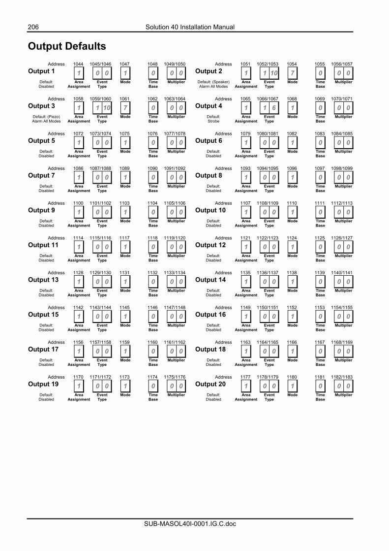
206 Solution 40 Installation Manual
SUB-MASOL40I-0001.IG.C.doc
Output Defaults Address 1044 1045/1046 1047 1048 1049/1050 Address 1051 1052/1053 1054 1055 1056/1057Output 1 1 0 0 1 0 0 0 Output 2 1 1 10 7 0 0 0
Default: Disabled
Area Assignment
Event Type
Mode Time Base
Multiplier Default: (Speaker) Alarm All Modes
Area Assignment
Event Type
Mode Time Base
Multiplier
Address 1058 1059/1060 1061 1062 1063/1064 Address 1065 1066/1067 1068 1069 1070/1071Output 3 1 1 10 7 0 0 0 Output 4 1 1 6 1 0 0 0
Default: (Piezo) Alarm All Modes
Area Assignment
Event Type
Mode Time Base
Multiplier Default: Strobe
Area Assignment
Event Type
Mode Time Base
Multiplier
Address 1072 1073/1074 1075 1076 1077/1078 Address 1079 1080/1081 1082 1083 1084/1085Output 5 1 0 0 1 0 0 0 Output 6 1 0 0 1 0 0 0
Default: Disabled
Area Assignment
Event Type
Mode Time Base
Multiplier Default: Disabled
Area Assignment
Event Type
Mode Time Base
Multiplier
Address 1086 1087/1088 1089 1090 1091/1092 Address 1093 1094/1095 1096 1097 1098/1099Output 7 1 0 0 1 0 0 0 Output 8 1 0 0 1 0 0 0
Default: Disabled
Area Assignment
Event Type
Mode Time Base
Multiplier Default: Disabled
Area Assignment
Event Type
Mode Time Base
Multiplier
Address 1100 1101/1102 1103 1104 1105/1106 Address 1107 1108/1109 1110 1111 1112/1113Output 9 1 0 0 1 0 0 0 Output 10 1 0 0 1 0 0 0
Default: Disabled
Area Assignment
Event Type
Mode Time Base
Multiplier Default: Disabled
Area Assignment
Event Type
Mode Time Base
Multiplier
Address 1114 1115/1116 1117 1118 1119/1120 Address 1121 1122/1123 1124 1125 1126/1127Output 11 1 0 0 1 0 0 0 Output 12 1 0 0 1 0 0 0
Default: Disabled
Area Assignment
Event Type
Mode Time Base
Multiplier Default: Disabled
Area Assignment
Event Type
Mode Time Base
Multiplier
Address 1128 1129/1130 1131 1132 1133/1134 Address 1135 1136/1137 1138 1139 1140/1141Output 13 1 0 0 1 0 0 0 Output 14 1 0 0 1 0 0 0
Default: Disabled
Area Assignment
Event Type
Mode Time Base
Multiplier Default: Disabled
Area Assignment
Event Type
Mode Time Base
Multiplier
Address 1142 1143/1144 1145 1146 1147/1148 Address 1149 1150/1151 1152 1153 1154/1155Output 15 1 0 0 1 0 0 0 Output 16 1 0 0 1 0 0 0
Default: Disabled
Area Assignment
Event Type
Mode Time Base
Multiplier Default: Disabled
Area Assignment
Event Type
Mode Time Base
Multiplier
Address 1156 1157/1158 1159 1160 1161/1162 Address 1163 1164/1165 1166 1167 1168/1169Output 17 1 0 0 1 0 0 0 Output 18 1 0 0 1 0 0 0
Default: Disabled
Area Assignment
Event Type
Mode Time Base
Multiplier Default: Disabled
Area Assignment
Event Type
Mode Time Base
Multiplier
Address 1170 1171/1172 1173 1174 1175/1176 Address 1177 1178/1179 1180 1181 1182/1183Output 19 1 0 0 1 0 0 0 Output 20 1 0 0 1 0 0 0
Default: Disabled
Area Assignment
Event Type
Mode Time Base
Multiplier Default: Disabled
Area Assignment
Event Type
Mode Time Base
Multiplier
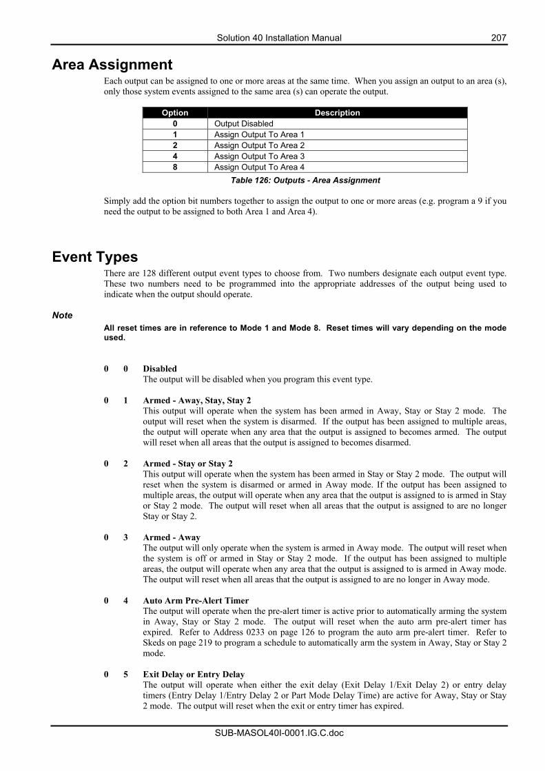
Solution 40 Installation Manual 207
SUB-MASOL40I-0001.IG.C.doc
Area Assignment Each output can be assigned to one or more areas at the same time. When you assign an output to an area (s), only those system events assigned to the same area (s) can operate the output.
Option Description 0 Output Disabled 1 Assign Output To Area 1 2 Assign Output To Area 2 4 Assign Output To Area 3 8 Assign Output To Area 4
Table 126: Outputs - Area Assignment Simply add the option bit numbers together to assign the output to one or more areas (e.g. program a 9 if you need the output to be assigned to both Area 1 and Area 4).
Event Types There are 128 different output event types to choose from. Two numbers designate each output event type. These two numbers need to be programmed into the appropriate addresses of the output being used to indicate when the output should operate.
Note
All reset times are in reference to Mode 1 and Mode 8. Reset times will vary depending on the mode used.
0 0 Disabled The output will be disabled when you program this event type. 0 1 Armed - Away, Stay, Stay 2 This output will operate when the system has been armed in Away, Stay or Stay 2 mode. The
output will reset when the system is disarmed. If the output has been assigned to multiple areas, the output will operate when any area that the output is assigned to becomes armed. The output will reset when all areas that the output is assigned to becomes disarmed.
0 2 Armed - Stay or Stay 2 This output will operate when the system has been armed in Stay or Stay 2 mode. The output will
reset when the system is disarmed or armed in Away mode. If the output has been assigned to multiple areas, the output will operate when any area that the output is assigned to is armed in Stay or Stay 2 mode. The output will reset when all areas that the output is assigned to are no longer Stay or Stay 2.
0 3 Armed - Away The output will only operate when the system is armed in Away mode. The output will reset when
the system is off or armed in Stay or Stay 2 mode. If the output has been assigned to multiple areas, the output will operate when any area that the output is assigned to is armed in Away mode. The output will reset when all areas that the output is assigned to are no longer in Away mode.
0 4 Auto Arm Pre-Alert Timer The output will operate when the pre-alert timer is active prior to automatically arming the system
in Away, Stay or Stay 2 mode. The output will reset when the auto arm pre-alert timer has expired. Refer to Address 0233 on page 126 to program the auto arm pre-alert timer. Refer to Skeds on page 219 to program a schedule to automatically arm the system in Away, Stay or Stay 2 mode.
0 5 Exit Delay or Entry Delay The output will operate when either the exit delay (Exit Delay 1/Exit Delay 2) or entry delay
timers (Entry Delay 1/Entry Delay 2 or Part Mode Delay Time) are active for Away, Stay or Stay 2 mode. The output will reset when the exit or entry timer has expired.
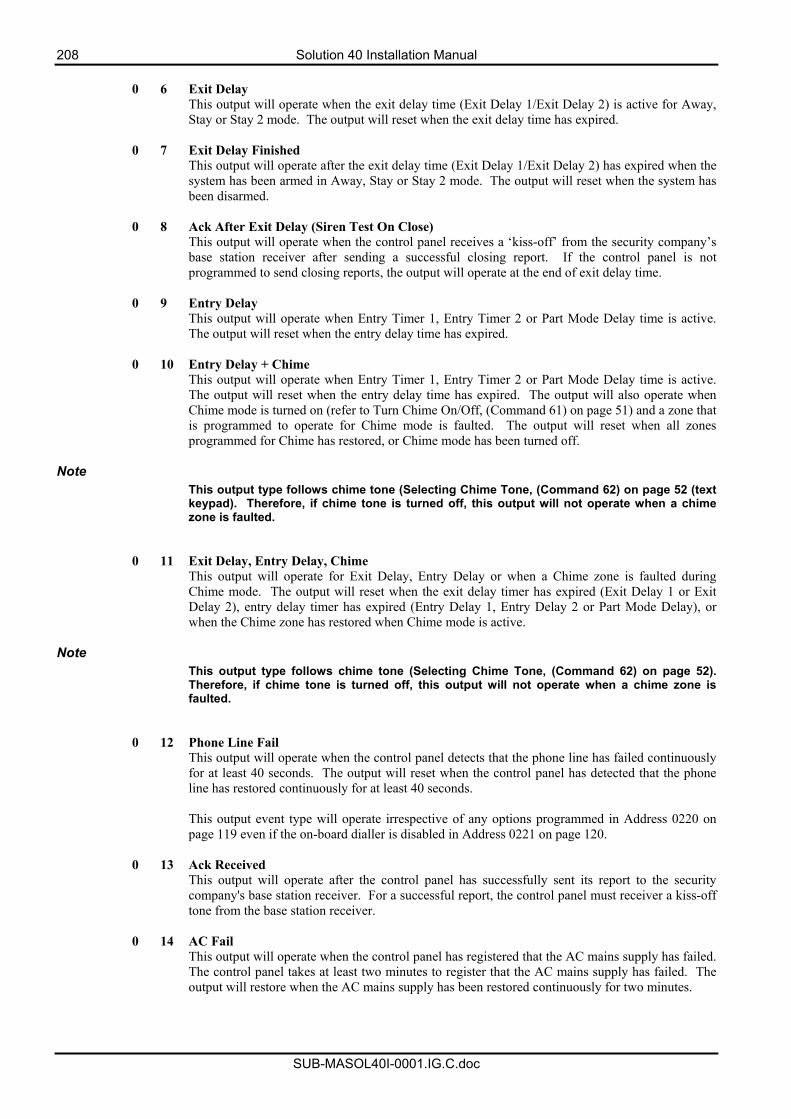
208 Solution 40 Installation Manual
SUB-MASOL40I-0001.IG.C.doc
0 6 Exit Delay
This output will operate when the exit delay time (Exit Delay 1/Exit Delay 2) is active for Away, Stay or Stay 2 mode. The output will reset when the exit delay time has expired.
0 7 Exit Delay Finished This output will operate after the exit delay time (Exit Delay 1/Exit Delay 2) has expired when the system has been armed in Away, Stay or Stay 2 mode. The output will reset when the system has been disarmed.
0 8 Ack After Exit Delay (Siren Test On Close)
This output will operate when the control panel receives a ‘kiss-off’ from the security company’s base station receiver after sending a successful closing report. If the control panel is not programmed to send closing reports, the output will operate at the end of exit delay time.
0 9 Entry Delay This output will operate when Entry Timer 1, Entry Timer 2 or Part Mode Delay time is active. The output will reset when the entry delay time has expired.
0 10 Entry Delay + Chime This output will operate when Entry Timer 1, Entry Timer 2 or Part Mode Delay time is active. The output will reset when the entry delay time has expired. The output will also operate when Chime mode is turned on (refer to Turn Chime On/Off, (Command 61) on page 51) and a zone that is programmed to operate for Chime mode is faulted. The output will reset when all zones programmed for Chime has restored, or Chime mode has been turned off.
Note This output type follows chime tone (Selecting Chime Tone, (Command 62) on page 52 (text keypad). Therefore, if chime tone is turned off, this output will not operate when a chime zone is faulted.
0 11 Exit Delay, Entry Delay, Chime This output will operate for Exit Delay, Entry Delay or when a Chime zone is faulted during Chime mode. The output will reset when the exit delay timer has expired (Exit Delay 1 or Exit Delay 2), entry delay timer has expired (Entry Delay 1, Entry Delay 2 or Part Mode Delay), or when the Chime zone has restored when Chime mode is active.
Note This output type follows chime tone (Selecting Chime Tone, (Command 62) on page 52). Therefore, if chime tone is turned off, this output will not operate when a chime zone is faulted.
0 12 Phone Line Fail This output will operate when the control panel detects that the phone line has failed continuously for at least 40 seconds. The output will reset when the control panel has detected that the phone line has restored continuously for at least 40 seconds. This output event type will operate irrespective of any options programmed in Address 0220 on page 119 even if the on-board dialler is disabled in Address 0221 on page 120.
0 13 Ack Received This output will operate after the control panel has successfully sent its report to the security company's base station receiver. For a successful report, the control panel must receiver a kiss-off tone from the base station receiver.
0 14 AC Fail
This output will operate when the control panel has registered that the AC mains supply has failed. The control panel takes at least two minutes to register that the AC mains supply has failed. The output will restore when the AC mains supply has been restored continuously for two minutes.
Solution 40 Installation Manual 209
SUB-MASOL40I-0001.IG.C.doc
0 15 Low Battery/Missing Battery
This output will operate when the control panel detects that the battery voltage has fallen below 12.1 volts or has been disconnected (missing). The output will reset when the control panel detects that the battery voltage has restored or has been replaced and reading 13.1 volts or higher under load.
1 0 PO2 Horn Speaker Supervision Fail
This output is only applicable when you have Option 1 programmed in Address 1039 on page 201. The output will operate when the system detects that the output device connected to PO2 becomes disconnected continuously for a period of 10 seconds. The output will restore when the control panel detects that the output device has been reconnected continuously for a period of 10 seconds.
Note
It is not recommended that you program PO2 as this output event type.
1 1 Sensor Trouble Monitor This output will operate when a zone assigned to a Zone Index Group that has Option 8 in Zone Options 1 programmed has failed to register a valid pulse within the sensor monitor time. The sensor monitor time is only active when the system is disarmed. The output will restore when the sensor device has again registered a valid pulse.
1 2 Duress
This output will operate when a PIN code assigned as a duress code is entered. The output will reset when you enter Command 47.
1 3 User Tamper This output will operate when an incorrect PIN Code has been entered more times than allowed in the User Code Tamper, Retry Count on page 164. The output will reset when Command 47 is used.
1 4 Disarm/Away/Stay Beeps (Keyswitch & RF Keyfob Arming)
This output will sound numerous short beeps when disarming the system, or arming in Away, Stay or Stay 2 mode via a keyswitch zone, RF keyfob or RPS software (1 beep = Off, 2 beeps = Away, 3 beeps = Stay or Stay 2). This output is intended for 12v DC buzzers or globes to be used.
1 5 Siren Time This output will sound for the duration of siren time programmed in Address 1040 on page 202 (default is 6 minutes) when an audible alarm condition activates siren time. This output is ready to operate when the system is off, or armed in Away, Stay, or Stay 2 mode for any alarm type.
1 6 Strobe
This output will operate as soon as siren time starts and will reset when a valid PIN code is entered. Refer to Address 1043 on page 203 to program any of the following options for the strobe output:
• Siren Time Starts Strobe Output • Output Type 1, 8 Starts Strobe Output • Output Type 1, 9 Starts Strobe Output • Output Type 1, 10 Starts Strobe Output • Output Type 1, 11 Starts Strobe Output
1 7 Silent Alarm
This output will operate when any non-fire zone assigned to a zone index configuration is programmed with Option 2 - Alarm Output on page 191 as disabled. This output does not operate for any silent emergency keys or user tamper alarm events. The output will continue until a valid PIN code has been entered or siren time has expired.
210 Solution 40 Installation Manual
SUB-MASOL40I-0001.IG.C.doc
1 8 Alarm - Away, Stay and Stay 2 (Non Fire) This output will operate if a user tamper alarm, emergency key alarm (non fire) or any zone alarm (non fire) has registered only when the system is armed in Away, Stay or Stay 2 mode. This output will not operate when the system is disarmed. The output will reset when a valid PIN code is entered or siren time has expired. This output will follow speaker beeps on page 201 for RF keyfob operations.
1 9 Alarm - Stay and Stay 2 (Non Fire)
This output will operate if a user tamper alarm, emergency key alarm (non fire) or any zone alarm (non fire) has registered only when the system is armed in Stay mode or Stay 2. This output will not operate when the system is disarmed or armed in Away mode. The output will reset when a valid PIN code is entered or siren time has expired. This output will follow speaker beeps on page 201 for RF keyfob operations.
1 10 Alarm - Off, Away, Stay and Stay 2 (Including Fire Alarms)
This output will operate if a user tamper alarm, emergency key alarm or any zone alarm has registered. The output will reset when a valid PIN code is entered or siren time has expired. This output will follow speaker beeps on page 201 for RF keyfob operations.
Note
Fire alarms will provide output in Temporal Code 3 format (pulses 3 half second pulses followed by a 1 second pause then repeat) for on-board outputs 1 – 4. Off-board outputs 5 – 20 will not provide Temporal Code 3 format for fire alarms.
1 11 Fire Alarm This output will only operate when a zone programmed as 24 hour fire or an emergency key programmed for fire has registered an alarm. The output will reset when siren time expires, or a valid PIN code is entered. Both the zone index group that is programmed for fire and the emergency key must be programmed as an audible alarm.
Note Fire alarms will provide output in Temporal Code 3 format (pulses 3 half second pulses followed by a 1 second pause then repeat) for on-board outputs 1 – 4. Off-board outputs 5 – 20 will not provide Temporal Code 3 format for fire alarms.
1 12 Fire Alarm Latching
This output will only operate when a zone programmed as 24 hour fire or an emergency key programmed for fire has registered an alarm. The output will only reset when you use Command 47. Both the zone index group that is programmed for fire and the emergency key must be programmed as an audible alarm.
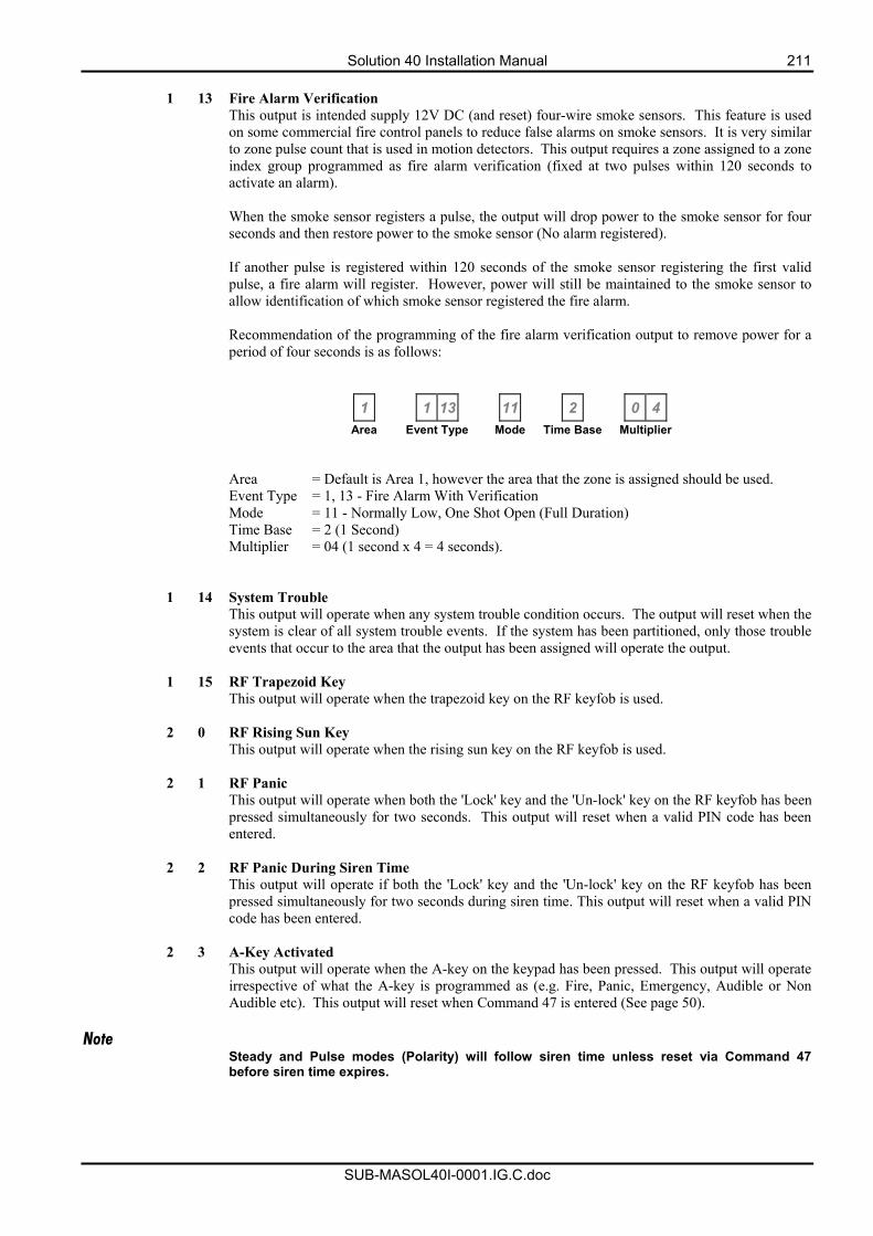
Solution 40 Installation Manual 211
SUB-MASOL40I-0001.IG.C.doc
1 13 Fire Alarm Verification
This output is intended supply 12V DC (and reset) four-wire smoke sensors. This feature is used on some commercial fire control panels to reduce false alarms on smoke sensors. It is very similar to zone pulse count that is used in motion detectors. This output requires a zone assigned to a zone index group programmed as fire alarm verification (fixed at two pulses within 120 seconds to activate an alarm).
When the smoke sensor registers a pulse, the output will drop power to the smoke sensor for four seconds and then restore power to the smoke sensor (No alarm registered).
If another pulse is registered within 120 seconds of the smoke sensor registering the first valid pulse, a fire alarm will register. However, power will still be maintained to the smoke sensor to allow identification of which smoke sensor registered the fire alarm.
Recommendation of the programming of the fire alarm verification output to remove power for a period of four seconds is as follows:
1 1 13 11 2 0 4
Area Event Type Mode Time Base Multiplier
Area = Default is Area 1, however the area that the zone is assigned should be used. Event Type = 1, 13 - Fire Alarm With Verification Mode = 11 - Normally Low, One Shot Open (Full Duration)
Time Base = 2 (1 Second) Multiplier = 04 (1 second x 4 = 4 seconds).
1 14 System Trouble
This output will operate when any system trouble condition occurs. The output will reset when the system is clear of all system trouble events. If the system has been partitioned, only those trouble events that occur to the area that the output has been assigned will operate the output.
1 15 RF Trapezoid Key This output will operate when the trapezoid key on the RF keyfob is used.
2 0 RF Rising Sun Key
This output will operate when the rising sun key on the RF keyfob is used.
2 1 RF Panic This output will operate when both the 'Lock' key and the 'Un-lock' key on the RF keyfob has been pressed simultaneously for two seconds. This output will reset when a valid PIN code has been entered.
2 2 RF Panic During Siren Time This output will operate if both the 'Lock' key and the 'Un-lock' key on the RF keyfob has been pressed simultaneously for two seconds during siren time. This output will reset when a valid PIN code has been entered.
2 3 A-Key Activated This output will operate when the A-key on the keypad has been pressed. This output will operate irrespective of what the A-key is programmed as (e.g. Fire, Panic, Emergency, Audible or Non Audible etc). This output will reset when Command 47 is entered (See page 50).
Note Steady and Pulse modes (Polarity) will follow siren time unless reset via Command 47 before siren time expires.
212 Solution 40 Installation Manual
SUB-MASOL40I-0001.IG.C.doc
2 4 B-Key Activated
This output will operate when the B-key on the keypad has been pressed. This output will operate irrespective of what the B-key is programmed as (e.g. Fire, Panic, Emergency, Audible or Non Audible etc). This output will reset when Command 47 is entered (See page 50).
Note Steady and Pulse modes (Polarity) will follow siren time unless reset via Command 47 before siren time expires.
2 5 C-Key Activated
This output will operate when the C-key on the keypad as been pressed. This output will operate irrespective of what the C-key is programmed as (e.g. Fire, Panic, Emergency, Audible or Non Audible etc). This output will reset when Command 47 is entered (See page 50).
2 6 Communication Fail After 3 Attempts
This output will operate if the control panel fails to successfully communicate after 3 attempts with the security company's base station receiver (or receiving party). The output will reset when Command 47 has been used, or after the first successful call.
Note Steady and Pulse modes (Polarity) will follow siren time unless reset via Command 47 before siren time expires.
2 7 Communication Fail
This output will operate if the control panel fails to successfully communicate to the security company's base station receiver (or receiving party) after the maximum number of attempts. This output will reset when Command 47 is entered (See page 50).
2 8 Panel Off Hook This output will operate when the control panel seizes the telephone line. The output will reset once the control panel has released the telephone line.
2 9 Ring Detect
This output will operate when the control panel detects an incoming call. The output will reset when the control panel no longer detects an incoming call, or has answered the call. Refer to Address 0213 on page 118 to program how many times the telephone should ring before the control panel will answer an incoming call.
2 10 Reserved 2 11 Follow Keypad Buzzer
This output will mimic the sound from the keypad buzzer. The output mode (polarity) is not applicable for this output event type. Therefore, programming the mode as zero will not disable the output.
2 12 Chime
This output will follow Chime tone option set in Command 62 (See page 52). The options include, Off, Short Beep (1 Second), Beep Till Key and Beep Till Closed. However, if the Chime tone is programmed as ‘Off’, the output will not operate, irrespective of the output mode.
2 13 Ready To Armed - No Controlled Zone Faulted
This output will only operate when the area is off and no controlled zone is faulted (e.g. Delay, Follower, Instant). The output will reset when the area is armed in Away, Stay or Stay 2 mode.
Note This output will remain active when the system is armed with or without a faulted zone.
Solution 40 Installation Manual 213
SUB-MASOL40I-0001.IG.C.doc
2 14 Exit Error
This output will operate when a Controlled Entry/Exit Delay zone faulted at the end of exit time. The output will reset when the system has been disarmed. Refer to Exit Error Reports Allowed on page 140 for more information.
2 15 AC 60 Hz/50 Hz
This output will operate if the AC mains supply frequency is 60 Htz. The output will reset when the AC mains supply frequency is 50 Htz.
3 0 Ground Start
This is an output programmed to activate for 0.5 seconds when the telephone line is seized. It is intended for use with ground start telephone systems that require a momentary short to ground for a dial tone to be obtained.
3 1 Follow Zone Index 1 3 9 Follow Zone Index 9 3 2 Follow Zone Index 2 3 10 Follow Zone Index 10 3 3 Follow Zone Index 3 3 11 Follow Zone Index 11 3 4 Follow Zone Index 4 3 12 Follow Zone Index 12 3 5 Follow Zone Index 5 3 13 Follow Zone Index 13 3 6 Follow Zone Index 6 3 14 Follow Zone Index 14 3 7 Follow Zone Index 7 3 15 Follow Zone Index 15 3 8 Follow Zone Index 8
The above outputs will operate when a zone assigned to the corresponding zone index becomes faulted. The output will reset when all zones assigned to the corresponding zone index have restored (normal). The output will operate irrespective of the system being disarmed, armed in Away, Stay or Stay 2 mode. The output will also operate if a zone that is faulted has been bypassed, or if the zone expansion module that the zone has been assigned to has failed (missing).
4 1 Alarm Zone Index 1 4 9 Alarm Zone Index 9 4 2 Alarm Zone Index 2 4 10 Alarm Zone Index 10 4 3 Alarm Zone Index 3 4 11 Alarm Zone Index 11 4 4 Alarm Zone Index 4 4 12 Alarm Zone Index 12 4 5 Alarm Zone Index 5 4 13 Alarm Zone Index 13 4 6 Alarm Zone Index 6 4 14 Alarm Zone Index 14 4 7 Alarm Zone Index 7 4 15 Alarm Zone Index 15 4 8 Alarm Zone Index 8
The above outputs will operate when a zone assigned to the corresponding zone index is in alarm, irrespective of the system being disarmed, armed in Away, Stay or Stay 2 mode (depending on the zone type programmed). The above outputs will operate for both audible and silent alarms. The output will also operate for exit error alarms or a zone trouble condition (if programmed) when the system is in Away, Stay or Stay 2 mode. For 24 hour zone types, the output will reset when the zone returns to normal. For controlled zone types, the output will reset when the zone returns to normal or the system has been disarmed.
5 0 Change Outputs This output is only used via Command 54. Use Command 54 to toggle on and off this output.
Refer to Toggle Outputs On/Off (Command 54) on page 62.
214 Solution 40 Installation Manual
SUB-MASOL40I-0001.IG.C.doc
5 1 Trouble Zone Index 1 5 9 Trouble Zone Index 9 5 2 Trouble Zone Index 2 5 10 Trouble Zone Index 10 5 3 Trouble Zone Index 3 5 11 Trouble Zone Index 11 5 4 Trouble Zone Index 4 5 12 Trouble Zone Index 12 5 5 Trouble Zone Index 5 5 13 Trouble Zone Index 13 5 6 Trouble Zone Index 6 5 14 Trouble Zone Index 14 5 7 Trouble Zone Index 7 5 15 Trouble Zone Index 15 5 8 Trouble Zone Index 8
The outputs above will operate when a zone assigned to the corresponding zone index is in a trouble condition. The output will reset when the zone has been restored.
6 1 Follow PIN Code 1 7 1 Follow PIN Code 17 6 2 Follow PIN Code 2 7 2 Follow PIN Code 18 6 3 Follow PIN Code 3 7 3 Follow PIN Code 19 6 4 Follow PIN Code 4 7 4 Follow PIN Code 20 6 5 Follow PIN Code 5 7 5 Follow PIN Code 21 6 6 Follow PIN Code 6 7 6 Follow PIN Code 22 6 7 Follow PIN Code 7 7 7 Follow PIN Code 23 6 8 Follow PIN Code 8 7 8 Follow PIN Code 24 6 9 Follow PIN Code 9 7 9 Follow PIN Code 25 6 10 Follow PIN Code 10 7 10 Follow PIN Code 26 6 11 Follow PIN Code 11 7 11 Follow PIN Code 27 6 12 Follow PIN Code 12 7 12 Follow PIN Code 28 6 13 Follow PIN Code 13 7 13 Follow PIN Code 29 6 14 Follow PIN Code 14 7 14 Follow PIN Code 30 6 15 Follow PIN Code 15 7 15 Follow PIN Code 31 7 0 Follow PIN Code 16 8 0 Follow PIN Code 32
These outputs will operate when the corresponding PIN code is entered. The output will reset the next time the corresponding PIN code is entered, or Command 54 has been used to reset the output.
8 1 Sked
You need to program a sked for this output to operate. The Sked will need to be assigned to the output that you want to turn on or turn off. Only outputs 1 - 15 can be used for this output event type. The output will reset when the one-shot timer has expired, Command 54 has been used to turn off the output, or another sked programmed to turn the output off. Refer to Skeds on page 219.
8 2 Command 54
This output can only be turned on and turned off via Command 54. Refer to Toggle Outputs On/Off (Command 54) on page 62. Command 54 can turn on and off other outputs.
8 4 Confirmed / Verified Alarm This output activates when the requirements for a confirmed / verified alarm are met. Resets when the confirmed alarm is reset.
8 5 Unconfirmed / Unverified Alarm This output activates when an unconfirmed / unverified alarm occurs. Resets when the confirmation alarm timer resets or a PIN is entered.
8 6 Tamper
This output activates on any tamper condition. Resets when the tamper condition restores.
8 7 Bypass This output activates when any input is bypassed. Resets when all input bypasses are cleared.
8 8 Enhanced Siren This output activates on exit delay, entry delay, chime, alarm, tamper or bad set. Resets at the end of bell time or when a PIN is entered.
Solution 40 Installation Manual 215
SUB-MASOL40I-0001.IG.C.doc
8 9 Alarm Cancelled This output activates on cancelled alarm. Reset when alarm is cleared.
8 10 Rf Transmitter Missing This output activates when any zone RF Transmitter is missing. Resets when the Rf Transmitter missing resets.
8 11 RF Transmitter Low Battery This output activates when any RF Transmitter, including zones as well as key fobs report a low battery condition. Resets when the low battery condition resets.
8 12 RF Receiver Jamming
This output activates when the receiver is in a jammed condition for five minutes. Resets when the RF receiver is no longer jammed.
8 13 Fire Alarm Only This output activates on fire alarm only. Resets on user or installer System Reset using Command 47. Does not pulse in temporal code 3 format ( fire siren pulse output).
8 14 Personal Alarm This output activates on 24 Hour Visible Panic Zone Function, Duress User or RF Keyfob Panic. Clears on user or installer System Reset, Command 47.
216 Solution 40 Installation Manual
SUB-MASOL40I-0001.IG.C.doc
Mode The output mode programs how the output will operate. Only one mode can be programmed for each output. Refer to Table 127: Outputs - Mode below.
Option Mode Description 0 Output Disabled 1 Normally Open, Going Low 2 Normally Open, Latching Low - Command 54 Reset 3 Toggle Output State 4 Normally Open, Pulsing Low 5 Normally Open, One Shot Low - Full Duration 6 Normally Open, One Shot Low - Retrigger 7 Normally Open, One Shot Low - Can Reset 8 Normally Low, Going Open 9 Normally Low, Latching Open - Command 54 Reset
10 Normally Low, Pulsing Low 11 Normally Low, One Shot Open - Full Duration 12 Normally Low, One Shot Open - Retrigger 13 Normally Low, One Shot Open - Can Reset
Table 127: Outputs - Mode Output Disabled (0) If an output is not required , the polarity should be programmed as zero. Normally Open, Going Low (1) This mode is normally open circuit and will switch to zero volts when the event occurs. The output will switch back to open circuit when the event has restored. Time parameters do not apply to this mode selection. Normally Open, Latching Low (2) This mode is normally open circuit and will switch to zero volts when the event occurs. The output will only switch back to open circuit when manually reset via Command 54 on page 62. Toggle Output State (3) This mode is normally open circuit and will switch to zero volts when the event occurs. The output will switch back to open circuit when the output event re-occurs. Normally Open, Pulsing Low (4) This mode is normally open circuit and will switch to pulsing zero volts when the event occurs. The output will switch back to open circuit when the output event restores or siren time expires. Normally Open, One Shot Low - Full Duration (5) This mode is normally open circuit and will switch to zero volts when the event occurs. The output will only switch back to open circuit when the duration of both the time base and multiplier has expired. This output cannot be manually reset, it will run for the full duration.
Solution 40 Installation Manual 217
SUB-MASOL40I-0001.IG.C.doc
Normally Open, One Shot Low - Retrigger (6) This one shot mode is normally open circuit and will switch to zero volts when the event occurs. Every time the event occurs, it will restart the one shot timer. The output will switch back to open circuit once the one shot time has expired. This mode is ideally suited for lighting control. A PIR can be used to trigger an output for turning On indicators. While ever there is movement, the PIR will re-trigger the output and lengthen the time the lights will remain on. Normally Open, One Shot Low - Can Reset (7) This one shot mode is normally open circuit and will switch to zero volts when the event occurs. The output will switch back to open circuit when the one shot time has expired, or when the event has returned to normal. This means the operation of the output can be shortened regardless of the time parameter programmed. Normally Low, Going Open (8) This mode is normally zero volts and will switch to open circuit when the event occurs. The output will switch back to zero volts when the event has restored. Time parameters do not apply. Normally Low, Latching Low (9) This mode is normally zero volts and will switch to open circuit when the event occurs. The output will only switch back to zero volts manually via Command 54 on page 62. Normally Low, Pulsing Open (10) This mode is normally zero volts and will switch to pulsing open circuit when the event occurs. The output will switch back to zero volts when the output event restores or siren time expires. Normally Low, One Shot Open - Full Duration (11) This mode is normally zero volts and will switch to open circuit when the event occurs. The output will only switch back to zero volts when the duration of both the time base and multiplier has expired. Normally Low, One Shot Open - Retrigger (12) This one shot mode is normally zero volts and will switch to open circuit when the event occurs. Every time the event occurs, it will restart the one shot timer. The output will switch back to zero volts once the one shot time has expired. Normally Low, One Shot Open - Can Reset (13) This one shot mode is normally zero volts and will switch to open circuit when the event occurs. The output will switch back to zero volts when the one shot time has expired, or when the event has returned to normal. This means the operation of the output can be shortened regardless of the time parameter programmed.
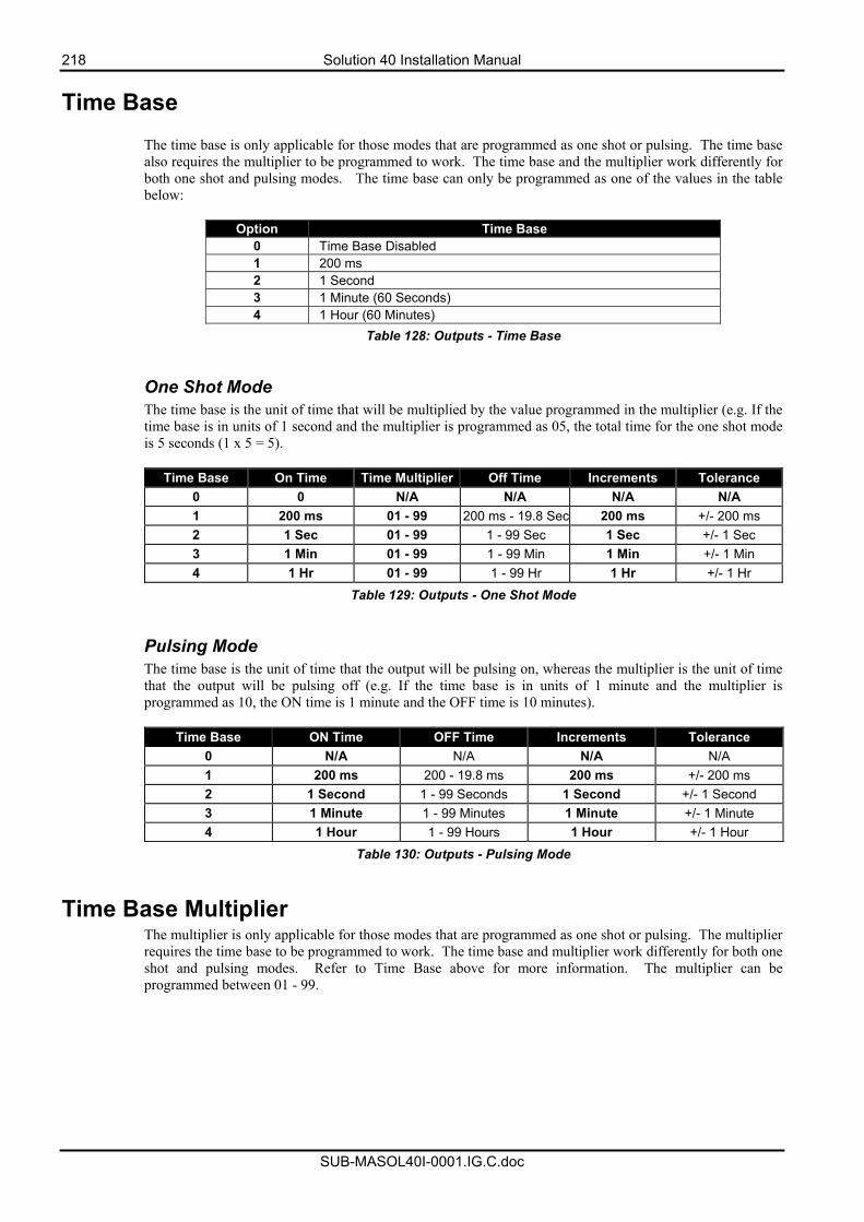
218 Solution 40 Installation Manual
SUB-MASOL40I-0001.IG.C.doc
Time Base
The time base is only applicable for those modes that are programmed as one shot or pulsing. The time base also requires the multiplier to be programmed to work. The time base and the multiplier work differently for both one shot and pulsing modes. The time base can only be programmed as one of the values in the table below:
Option Time Base 0 Time Base Disabled 1 200 ms 2 1 Second 3 1 Minute (60 Seconds) 4 1 Hour (60 Minutes)
Table 128: Outputs - Time Base One Shot Mode The time base is the unit of time that will be multiplied by the value programmed in the multiplier (e.g. If the time base is in units of 1 second and the multiplier is programmed as 05, the total time for the one shot mode is 5 seconds (1 x 5 = 5).
Time Base On Time Time Multiplier Off Time Increments Tolerance 0 0 N/A N/A N/A N/A 1 200 ms 01 - 99 200 ms - 19.8 Sec 200 ms +/- 200 ms 2 1 Sec 01 - 99 1 - 99 Sec 1 Sec +/- 1 Sec 3 1 Min 01 - 99 1 - 99 Min 1 Min +/- 1 Min 4 1 Hr 01 - 99 1 - 99 Hr 1 Hr +/- 1 Hr
Table 129: Outputs - One Shot Mode
Pulsing Mode The time base is the unit of time that the output will be pulsing on, whereas the multiplier is the unit of time that the output will be pulsing off (e.g. If the time base is in units of 1 minute and the multiplier is programmed as 10, the ON time is 1 minute and the OFF time is 10 minutes).
Time Base ON Time OFF Time Increments Tolerance 0 N/A N/A N/A N/A 1 200 ms 200 - 19.8 ms 200 ms +/- 200 ms 2 1 Second 1 - 99 Seconds 1 Second +/- 1 Second 3 1 Minute 1 - 99 Minutes 1 Minute +/- 1 Minute 4 1 Hour 1 - 99 Hours 1 Hour +/- 1 Hour
Table 130: Outputs - Pulsing Mode
Time Base Multiplier The multiplier is only applicable for those modes that are programmed as one shot or pulsing. The multiplier requires the time base to be programmed to work. The time base and multiplier work differently for both one shot and pulsing modes. Refer to Time Base above for more information. The multiplier can be programmed between 01 - 99.
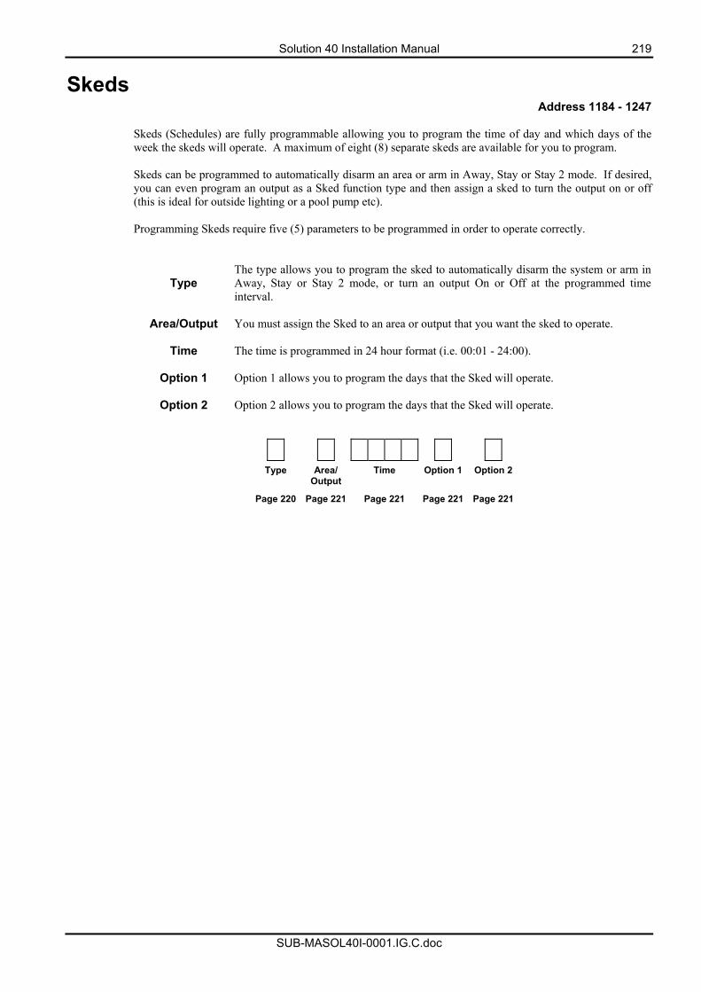
Solution 40 Installation Manual 219
SUB-MASOL40I-0001.IG.C.doc
Skeds Address 1184 - 1247
Skeds (Schedules) are fully programmable allowing you to program the time of day and which days of the week the skeds will operate. A maximum of eight (8) separate skeds are available for you to program. Skeds can be programmed to automatically disarm an area or arm in Away, Stay or Stay 2 mode. If desired, you can even program an output as a Sked function type and then assign a sked to turn the output on or off (this is ideal for outside lighting or a pool pump etc). Programming Skeds require five (5) parameters to be programmed in order to operate correctly.
Type The type allows you to program the sked to automatically disarm the system or arm in Away, Stay or Stay 2 mode, or turn an output On or Off at the programmed time interval.
Area/Output You must assign the Sked to an area or output that you want the sked to operate.
Time The time is programmed in 24 hour format (i.e. 00:01 - 24:00).
Option 1 Option 1 allows you to program the days that the Sked will operate.
Option 2 Option 2 allows you to program the days that the Sked will operate.
Type Area/ Output
Time Option 1 Option 2
Page 220 Page 221 Page 221 Page 221 Page 221
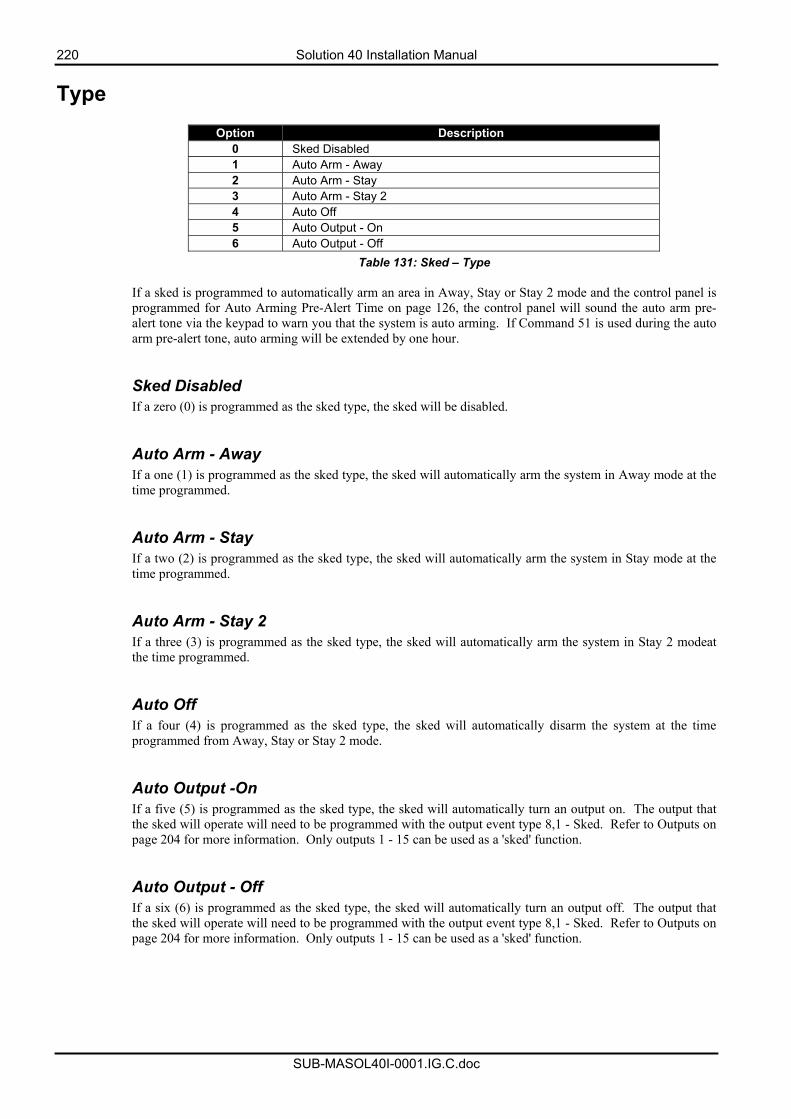
220 Solution 40 Installation Manual
SUB-MASOL40I-0001.IG.C.doc
Type
Option Description 0 Sked Disabled 1 Auto Arm - Away 2 Auto Arm - Stay 3 Auto Arm - Stay 2 4 Auto Off 5 Auto Output - On 6 Auto Output - Off
Table 131: Sked – Type
If a sked is programmed to automatically arm an area in Away, Stay or Stay 2 mode and the control panel is programmed for Auto Arming Pre-Alert Time on page 126, the control panel will sound the auto arm pre-alert tone via the keypad to warn you that the system is auto arming. If Command 51 is used during the auto arm pre-alert tone, auto arming will be extended by one hour.
Sked Disabled If a zero (0) is programmed as the sked type, the sked will be disabled. Auto Arm - Away If a one (1) is programmed as the sked type, the sked will automatically arm the system in Away mode at the time programmed.
Auto Arm - Stay If a two (2) is programmed as the sked type, the sked will automatically arm the system in Stay mode at the time programmed.
Auto Arm - Stay 2 If a three (3) is programmed as the sked type, the sked will automatically arm the system in Stay 2 modeat the time programmed.
Auto Off If a four (4) is programmed as the sked type, the sked will automatically disarm the system at the time programmed from Away, Stay or Stay 2 mode.
Auto Output -On If a five (5) is programmed as the sked type, the sked will automatically turn an output on. The output that the sked will operate will need to be programmed with the output event type 8,1 - Sked. Refer to Outputs on page 204 for more information. Only outputs 1 - 15 can be used as a 'sked' function.
Auto Output - Off If a six (6) is programmed as the sked type, the sked will automatically turn an output off. The output that the sked will operate will need to be programmed with the output event type 8,1 - Sked. Refer to Outputs on page 204 for more information. Only outputs 1 - 15 can be used as a 'sked' function.
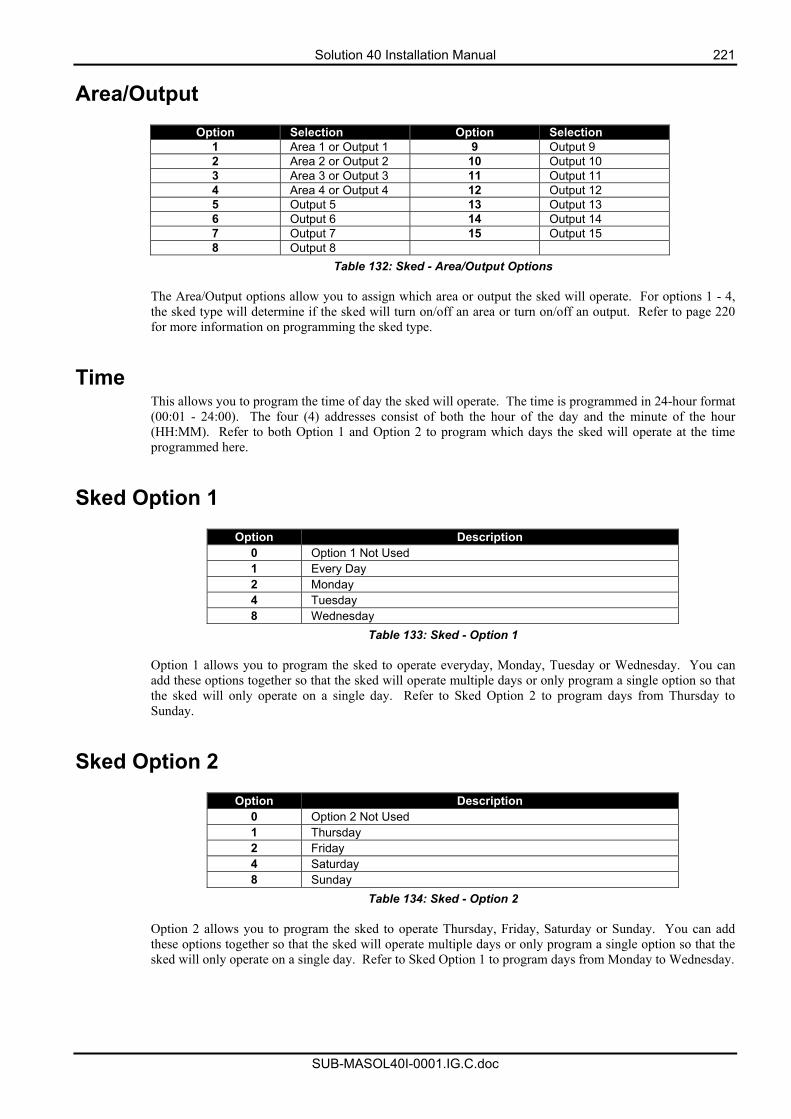
Solution 40 Installation Manual 221
SUB-MASOL40I-0001.IG.C.doc
Area/Output
Option Selection Option Selection 1 Area 1 or Output 1 9 Output 9 2 Area 2 or Output 2 10 Output 10 3 Area 3 or Output 3 11 Output 11 4 Area 4 or Output 4 12 Output 12 5 Output 5 13 Output 13 6 Output 6 14 Output 14 7 Output 7 15 Output 15 8 Output 8
Table 132: Sked - Area/Output Options
The Area/Output options allow you to assign which area or output the sked will operate. For options 1 - 4, the sked type will determine if the sked will turn on/off an area or turn on/off an output. Refer to page 220 for more information on programming the sked type.
Time This allows you to program the time of day the sked will operate. The time is programmed in 24-hour format (00:01 - 24:00). The four (4) addresses consist of both the hour of the day and the minute of the hour (HH:MM). Refer to both Option 1 and Option 2 to program which days the sked will operate at the time programmed here.
Sked Option 1
Option Description 0 Option 1 Not Used 1 Every Day 2 Monday 4 Tuesday 8 Wednesday
Table 133: Sked - Option 1 Option 1 allows you to program the sked to operate everyday, Monday, Tuesday or Wednesday. You can add these options together so that the sked will operate multiple days or only program a single option so that the sked will only operate on a single day. Refer to Sked Option 2 to program days from Thursday to Sunday.
Sked Option 2
Option Description 0 Option 2 Not Used 1 Thursday 2 Friday 4 Saturday 8 Sunday
Table 134: Sked - Option 2 Option 2 allows you to program the sked to operate Thursday, Friday, Saturday or Sunday. You can add these options together so that the sked will operate multiple days or only program a single option so that the sked will only operate on a single day. Refer to Sked Option 1 to program days from Monday to Wednesday.
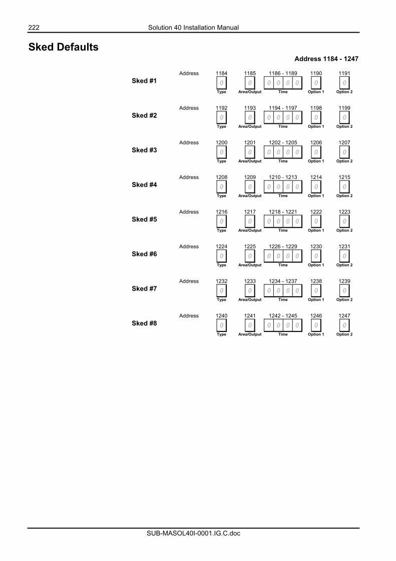
222 Solution 40 Installation Manual
SUB-MASOL40I-0001.IG.C.doc
Sked Defaults Address 1184 - 1247
Address 1184 1185 1186 - 1189 1190 1191 Sked #1 0 0 0 0 0 0 0 0 Type Area/Output Time Option 1 Option 2
Address 1192 1193 1194 - 1197 1198 1199 Sked #2 0 0 0 0 0 0 0 0 Type Area/Output Time Option 1 Option 2
Address 1200 1201 1202 - 1205 1206 1207 Sked #3 0 0 0 0 0 0 0 0 Type Area/Output Time Option 1 Option 2
Address 1208 1209 1210 - 1213 1214 1215 Sked #4 0 0 0 0 0 0 0 0 Type Area/Output Time Option 1 Option 2
Address 1216 1217 1218 - 1221 1222 1223 Sked #5 0 0 0 0 0 0 0 0 Type Area/Output Time Option 1 Option 2
Address 1224 1225 1226 - 1229 1230 1231 Sked #6 0 0 0 0 0 0 0 0 Type Area/Output Time Option 1 Option 2
Address 1232 1233 1234 - 1237 1238 1239 Sked #7 0 0 0 0 0 0 0 0 Type Area/Output Time Option 1 Option 2
Address 1240 1241 1242 - 1245 1246 1247 Sked #8 0 0 0 0 0 0 0 0 Type Area/Output Time Option 1 Option 2
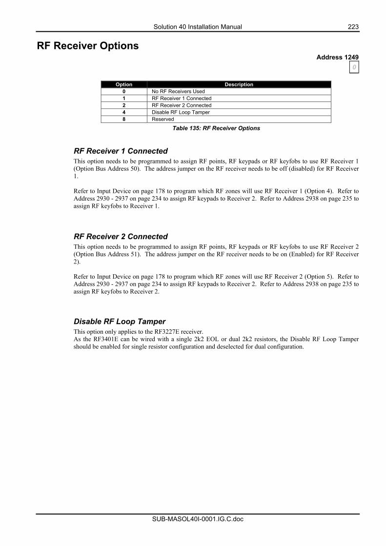
Solution 40 Installation Manual 223
SUB-MASOL40I-0001.IG.C.doc
RF Receiver Options Address 1249
0
Option Description 0 No RF Receivers Used 1 RF Receiver 1 Connected 2 RF Receiver 2 Connected 4 Disable RF Loop Tamper 8 Reserved
Table 135: RF Receiver Options RF Receiver 1 Connected This option needs to be programmed to assign RF points, RF keypads or RF keyfobs to use RF Receiver 1 (Option Bus Address 50). The address jumper on the RF receiver needs to be off (disabled) for RF Receiver 1. Refer to Input Device on page 178 to program which RF zones will use RF Receiver 1 (Option 4). Refer to Address 2930 - 2937 on page 234 to assign RF keypads to Receiver 2. Refer to Address 2938 on page 235 to assign RF keyfobs to Receiver 1. RF Receiver 2 Connected This option needs to be programmed to assign RF points, RF keypads or RF keyfobs to use RF Receiver 2 (Option Bus Address 51). The address jumper on the RF receiver needs to be on (Enabled) for RF Receiver 2). Refer to Input Device on page 178 to program which RF zones will use RF Receiver 2 (Option 5). Refer to Address 2930 - 2937 on page 234 to assign RF keypads to Receiver 2. Refer to Address 2938 on page 235 to assign RF keyfobs to Receiver 2. Disable RF Loop Tamper This option only applies to the RF3227E receiver. As the RF3401E can be wired with a single 2k2 EOL or dual 2k2 resistors, the Disable RF Loop Tamper should be enabled for single resistor configuration and deselected for dual configuration.
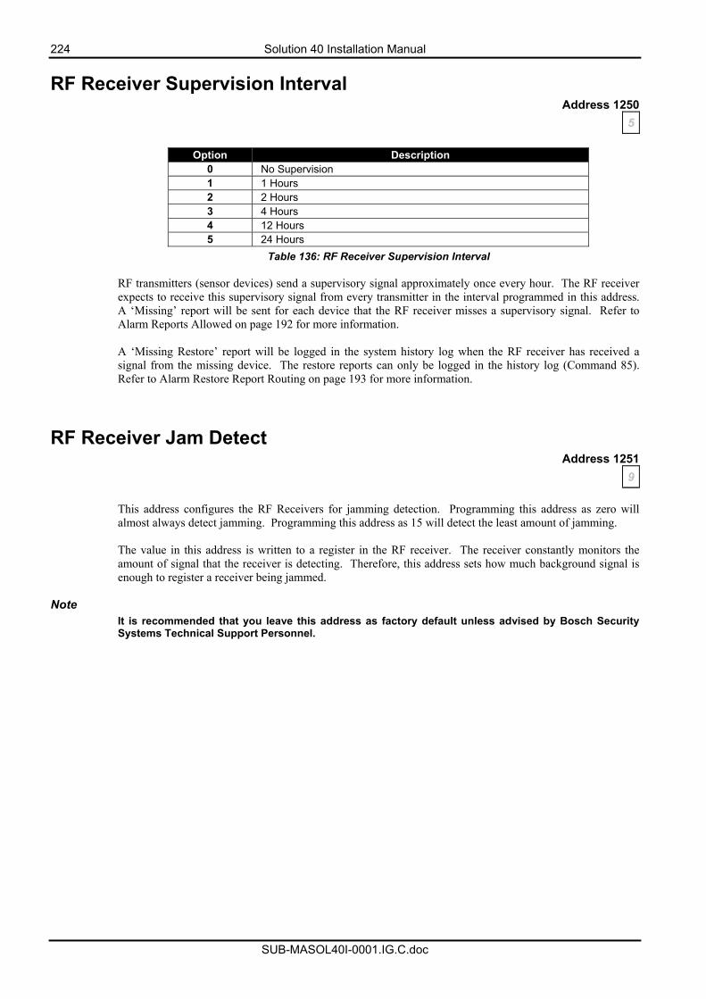
224 Solution 40 Installation Manual
SUB-MASOL40I-0001.IG.C.doc
RF Receiver Supervision Interval Address 1250
5
Option Description 0 No Supervision 1 1 Hours 2 2 Hours 3 4 Hours 4 12 Hours 5 24 Hours
Table 136: RF Receiver Supervision Interval RF transmitters (sensor devices) send a supervisory signal approximately once every hour. The RF receiver expects to receive this supervisory signal from every transmitter in the interval programmed in this address. A ‘Missing’ report will be sent for each device that the RF receiver misses a supervisory signal. Refer to Alarm Reports Allowed on page 192 for more information. A ‘Missing Restore’ report will be logged in the system history log when the RF receiver has received a signal from the missing device. The restore reports can only be logged in the history log (Command 85). Refer to Alarm Restore Report Routing on page 193 for more information.
RF Receiver Jam Detect Address 1251
9 This address configures the RF Receivers for jamming detection. Programming this address as zero will almost always detect jamming. Programming this address as 15 will detect the least amount of jamming. The value in this address is written to a register in the RF receiver. The receiver constantly monitors the amount of signal that the receiver is detecting. Therefore, this address sets how much background signal is enough to register a receiver being jammed.
Note It is recommended that you leave this address as factory default unless advised by Bosch Security Systems Technical Support Personnel.
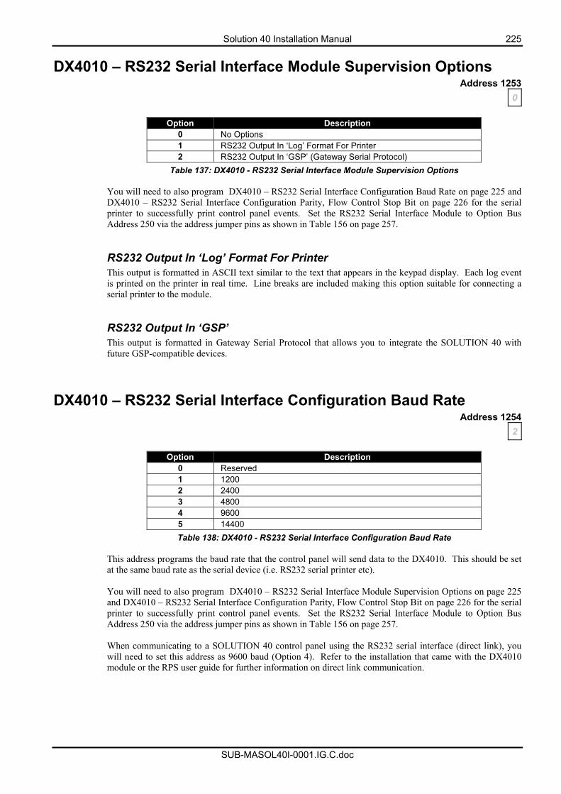
Solution 40 Installation Manual 225
SUB-MASOL40I-0001.IG.C.doc
DX4010 – RS232 Serial Interface Module Supervision Options Address 1253
0
Option Description 0 No Options 1 RS232 Output In ‘Log’ Format For Printer 2 RS232 Output In ‘GSP’ (Gateway Serial Protocol)
Table 137: DX4010 - RS232 Serial Interface Module Supervision Options
You will need to also program DX4010 – RS232 Serial Interface Configuration Baud Rate on page 225 and DX4010 – RS232 Serial Interface Configuration Parity, Flow Control Stop Bit on page 226 for the serial printer to successfully print control panel events. Set the RS232 Serial Interface Module to Option Bus Address 250 via the address jumper pins as shown in Table 156 on page 257. RS232 Output In ‘Log’ Format For Printer This output is formatted in ASCII text similar to the text that appears in the keypad display. Each log event is printed on the printer in real time. Line breaks are included making this option suitable for connecting a serial printer to the module. RS232 Output In ‘GSP’ This output is formatted in Gateway Serial Protocol that allows you to integrate the SOLUTION 40 with future GSP-compatible devices.
DX4010 – RS232 Serial Interface Configuration Baud Rate Address 1254
2
Option Description 0 Reserved 1 1200 2 2400 3 4800 4 9600 5 14400 Table 138: DX4010 - RS232 Serial Interface Configuration Baud Rate
This address programs the baud rate that the control panel will send data to the DX4010. This should be set at the same baud rate as the serial device (i.e. RS232 serial printer etc). You will need to also program DX4010 – RS232 Serial Interface Module Supervision Options on page 225 and DX4010 – RS232 Serial Interface Configuration Parity, Flow Control Stop Bit on page 226 for the serial printer to successfully print control panel events. Set the RS232 Serial Interface Module to Option Bus Address 250 via the address jumper pins as shown in Table 156 on page 257.
When communicating to a SOLUTION 40 control panel using the RS232 serial interface (direct link), you will need to set this address as 9600 baud (Option 4). Refer to the installation that came with the DX4010 module or the RPS user guide for further information on direct link communication.
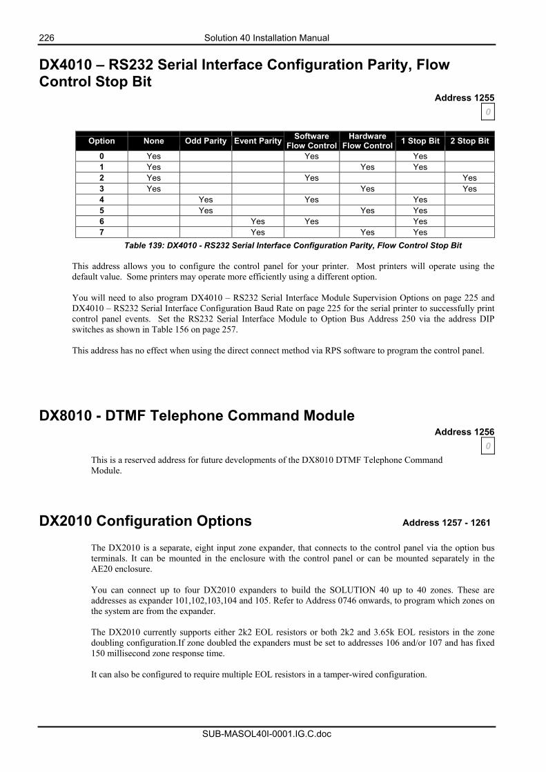
226 Solution 40 Installation Manual
SUB-MASOL40I-0001.IG.C.doc
DX4010 – RS232 Serial Interface Configuration Parity, Flow Control Stop Bit
Address 1255 0
Option None Odd Parity Event Parity Software
Flow ControlHardware
Flow Control 1 Stop Bit 2 Stop Bit
0 Yes Yes Yes 1 Yes Yes Yes 2 Yes Yes Yes 3 Yes Yes Yes 4 Yes Yes Yes 5 Yes Yes Yes 6 Yes Yes Yes 7 Yes Yes Yes
Table 139: DX4010 - RS232 Serial Interface Configuration Parity, Flow Control Stop Bit This address allows you to configure the control panel for your printer. Most printers will operate using the default value. Some printers may operate more efficiently using a different option. You will need to also program DX4010 – RS232 Serial Interface Module Supervision Options on page 225 and DX4010 – RS232 Serial Interface Configuration Baud Rate on page 225 for the serial printer to successfully print control panel events. Set the RS232 Serial Interface Module to Option Bus Address 250 via the address DIP switches as shown in Table 156 on page 257. This address has no effect when using the direct connect method via RPS software to program the control panel.
DX8010 - DTMF Telephone Command Module
Address 1256 0
This is a reserved address for future developments of the DX8010 DTMF Telephone Command Module.
DX2010 Configuration Options Address 1257 - 1261
The DX2010 is a separate, eight input zone expander, that connects to the control panel via the option bus terminals. It can be mounted in the enclosure with the control panel or can be mounted separately in the AE20 enclosure. You can connect up to four DX2010 expanders to build the SOLUTION 40 up to 40 zones. These are addresses as expander 101,102,103,104 and 105. Refer to Address 0746 onwards, to program which zones on the system are from the expander. The DX2010 currently supports either 2k2 EOL resistors or both 2k2 and 3.65k EOL resistors in the zone doubling configuration.If zone doubled the expanders must be set to addresses 106 and/or 107 and has fixed 150 millisecond zone response time. It can also be configured to require multiple EOL resistors in a tamper-wired configuration.
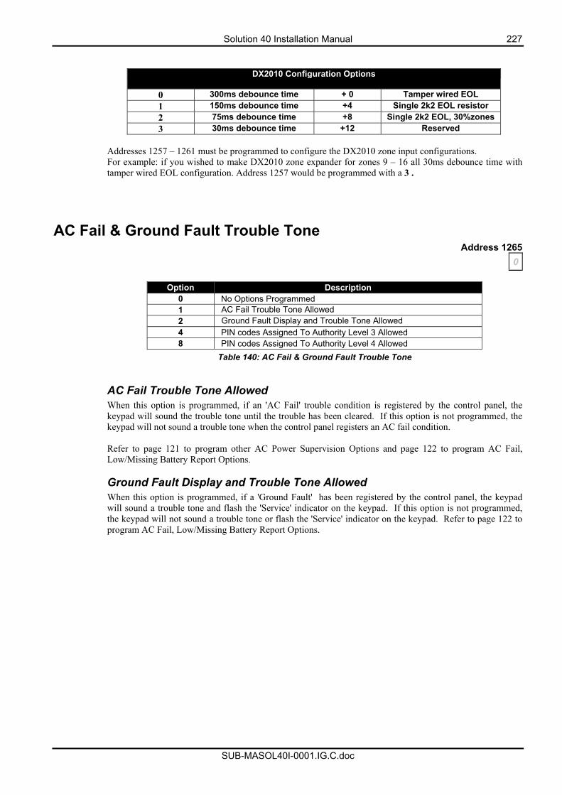
Solution 40 Installation Manual 227
SUB-MASOL40I-0001.IG.C.doc
DX2010 Configuration Options
0 300ms debounce time + 0 Tamper wired EOL 1 150ms debounce time +4 Single 2k2 EOL resistor 2 75ms debounce time +8 Single 2k2 EOL, 30%zones 3 30ms debounce time +12 Reserved
Addresses 1257 – 1261 must be programmed to configure the DX2010 zone input configurations. For example: if you wished to make DX2010 zone expander for zones 9 – 16 all 30ms debounce time with tamper wired EOL configuration. Address 1257 would be programmed with a 3 .
AC Fail & Ground Fault Trouble Tone Address 1265
0
Option Description 0 No Options Programmed 1 AC Fail Trouble Tone Allowed 2 Ground Fault Display and Trouble Tone Allowed 4 PIN codes Assigned To Authority Level 3 Allowed 8 PIN codes Assigned To Authority Level 4 Allowed
Table 140: AC Fail & Ground Fault Trouble Tone AC Fail Trouble Tone Allowed When this option is programmed, if an 'AC Fail' trouble condition is registered by the control panel, the keypad will sound the trouble tone until the trouble has been cleared. If this option is not programmed, the keypad will not sound a trouble tone when the control panel registers an AC fail condition. Refer to page 121 to program other AC Power Supervision Options and page 122 to program AC Fail, Low/Missing Battery Report Options. Ground Fault Display and Trouble Tone Allowed When this option is programmed, if a 'Ground Fault' has been registered by the control panel, the keypad will sound a trouble tone and flash the 'Service' indicator on the keypad. If this option is not programmed, the keypad will not sound a trouble tone or flash the 'Service' indicator on the keypad. Refer to page 122 to program AC Fail, Low/Missing Battery Report Options.
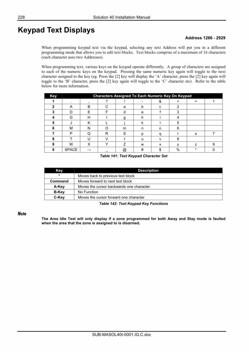
228 Solution 40 Installation Manual
SUB-MASOL40I-0001.IG.C.doc
Keypad Text Displays Address 1266 - 2929
When programming keypad text via the keypad, selecting any text Address will put you in a different programming mode that allows you to edit text blocks. Text blocks comprise of a maximum of 16 characters (each character uses two Addresses). When programming text, various keys on the keypad operate differently. A group of characters are assigned to each of the numeric keys on the keypad. Pressing the same numeric key again will toggle to the next character assigned to the key (eg. Press the [2] key will display the ‘A’ character, press the [2] key again will toggle to the ‘B’ character, press the [2] key again will toggle to the ‘C’ character etc). Refer to the table below for more information.
Key Characters Assigned To Each Numeric Key On Keypad
1 . , ? ! - & < > 1 2 A B C a b c 2 3 D E F d e f 3 4 G H I g h i 4 5 J K L j k l 5 6 M N O m n o 6 7 P Q R S p q r s 7 8 T U V t u v 8 9 W X Y Z w x y z 9 0 SPACE → _ @ # $ % * 0
Table 141: Text Keypad Character Set
Key Description * Moves back to previous text block
Command Moves forward to next text block A-Key Moves the cursor backwards one character B-Key No Function C-Key Moves the cursor forward one character
Table 142: Text Keypad Key Functions Note
The Area Idle Text will only display if a zone programmed for both Away and Stay mode is faulted when the area that the zone is assigned to is disarmed.
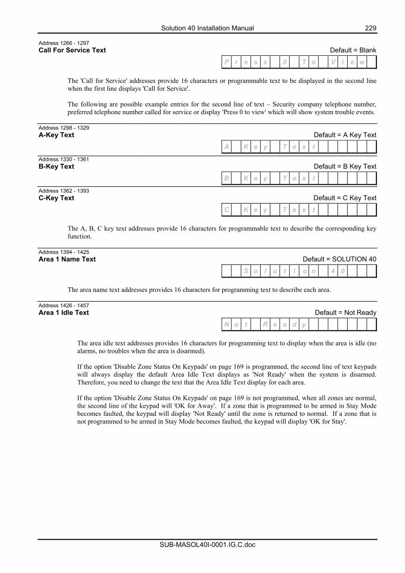
Solution 40 Installation Manual 229
SUB-MASOL40I-0001.IG.C.doc
Address 1266 - 1297 Call For Service Text Default = Blank
P r e s s 0 T o V i e w
The 'Call for Service' addresses provide 16 characters or programmable text to be displayed in the second line when the first line displays 'Call for Service'. The following are possible example entries for the second line of text – Security company telephone number, preferred telephone number called for service or display 'Press 0 to view' which will show system trouble events.
Address 1298 - 1329 A-Key Text Default = A Key Text
A K e y T e x t
Address 1330 - 1361 B-Key Text Default = B Key Text
B K e y T e x t
Address 1362 - 1393 C-Key Text Default = C Key Text
C K e y T e x t
The A, B, C key text addresses provide 16 characters for programmable text to describe the corresponding key function.
Address 1394 - 1425 Area 1 Name Text Default = SOLUTION 40
S o l u t i o n 4 0
The area name text addresses provides 16 characters for programming text to describe each area.
Address 1426 - 1457 Area 1 Idle Text Default = Not Ready
N o t R e a d y
The area idle text addresses provides 16 characters for programming text to display when the area is idle (no alarms, no troubles when the area is disarmed).
If the option 'Disable Zone Status On Keypads' on page 169 is programmed, the second line of text keypads will always display the default Area Idle Text displays as 'Not Ready' when the system is disarmed. Therefore, you need to change the text that the Area Idle Text display for each area. If the option 'Disable Zone Status On Keypads' on page 169 is not programmed, when all zones are normal, the second line of the keypad will 'OK for Away'. If a zone that is programmed to be armed in Stay Mode becomes faulted, the keypad will display 'Not Ready' until the zone is returned to normal. If a zone that is not programmed to be armed in Stay Mode becomes faulted, the keypad will display 'OK for Stay'.
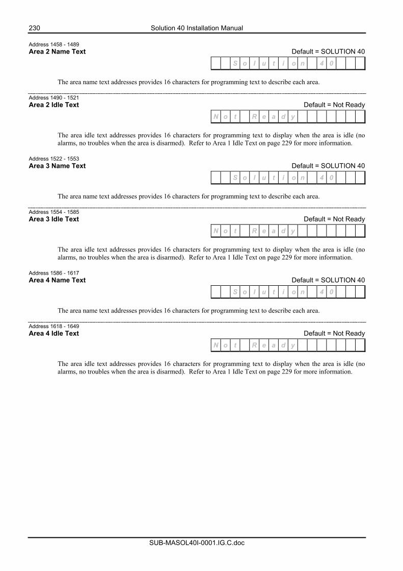
230 Solution 40 Installation Manual
SUB-MASOL40I-0001.IG.C.doc
Address 1458 - 1489 Area 2 Name Text Default = SOLUTION 40
S o l u t i o n 4 0
The area name text addresses provides 16 characters for programming text to describe each area. Address 1490 - 1521 Area 2 Idle Text Default = Not Ready
N o t R e a d y
The area idle text addresses provides 16 characters for programming text to display when the area is idle (no alarms, no troubles when the area is disarmed). Refer to Area 1 Idle Text on page 229 for more information.
Address 1522 - 1553 Area 3 Name Text Default = SOLUTION 40
S o l u t i o n 4 0
The area name text addresses provides 16 characters for programming text to describe each area. Address 1554 - 1585 Area 3 Idle Text Default = Not Ready
N o t R e a d y
The area idle text addresses provides 16 characters for programming text to display when the area is idle (no alarms, no troubles when the area is disarmed). Refer to Area 1 Idle Text on page 229 for more information.
Address 1586 - 1617 Area 4 Name Text Default = SOLUTION 40
S o l u t i o n 4 0
The area name text addresses provides 16 characters for programming text to describe each area. Address 1618 - 1649 Area 4 Idle Text Default = Not Ready
N o t R e a d y
The area idle text addresses provides 16 characters for programming text to display when the area is idle (no alarms, no troubles when the area is disarmed). Refer to Area 1 Idle Text on page 229 for more information.
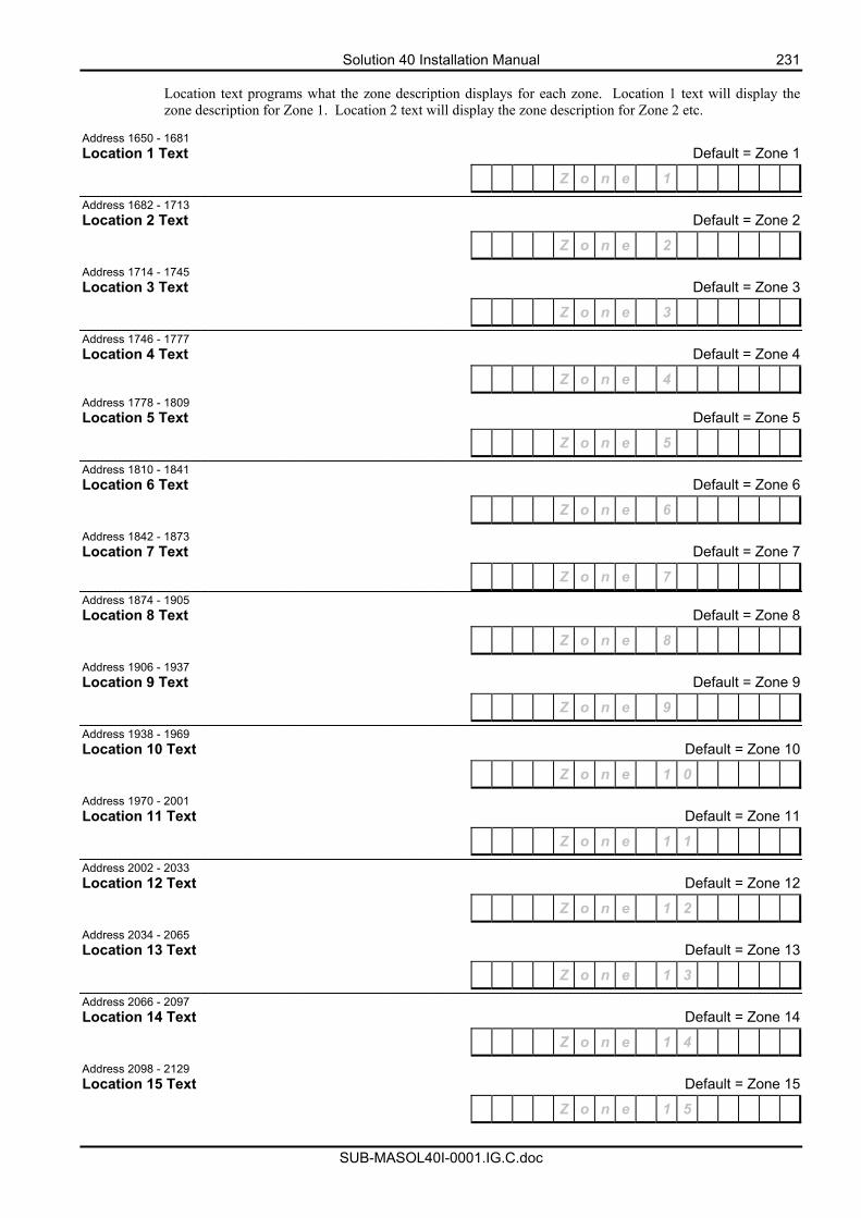
Solution 40 Installation Manual 231
SUB-MASOL40I-0001.IG.C.doc
Location text programs what the zone description displays for each zone. Location 1 text will display the zone description for Zone 1. Location 2 text will display the zone description for Zone 2 etc.
Address 1650 - 1681 Location 1 Text Default = Zone 1
Z o n e 1
Address 1682 - 1713 Location 2 Text Default = Zone 2
Z o n e 2
Address 1714 - 1745 Location 3 Text Default = Zone 3
Z o n e 3
Address 1746 - 1777 Location 4 Text Default = Zone 4
Z o n e 4 Address 1778 - 1809 Location 5 Text Default = Zone 5
Z o n e 5
Address 1810 - 1841 Location 6 Text Default = Zone 6
Z o n e 6
Address 1842 - 1873 Location 7 Text Default = Zone 7
Z o n e 7 Address 1874 - 1905 Location 8 Text Default = Zone 8
Z o n e 8
Address 1906 - 1937 Location 9 Text Default = Zone 9
Z o n e 9
Address 1938 - 1969 Location 10 Text Default = Zone 10
Z o n e 1 0
Address 1970 - 2001 Location 11 Text Default = Zone 11
Z o n e 1 1
Address 2002 - 2033 Location 12 Text Default = Zone 12
Z o n e 1 2
Address 2034 - 2065 Location 13 Text Default = Zone 13
Z o n e 1 3
Address 2066 - 2097 Location 14 Text Default = Zone 14
Z o n e 1 4
Address 2098 - 2129 Location 15 Text Default = Zone 15
Z o n e 1 5
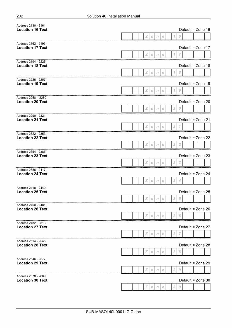
232 Solution 40 Installation Manual
SUB-MASOL40I-0001.IG.C.doc
Address 2130 - 2161 Location 16 Text Default = Zone 16
Z o n e 1 6
Address 2162 - 2193 Location 17 Text Default = Zone 17
Z o n e 1 7
Address 2194 - 2225 Location 18 Text Default = Zone 18
Z o n e 1 8
Address 2226 - 2257 Location 19 Text Default = Zone 19
Z o n e 1 9
Address 2258 – 2289 Location 20 Text Default = Zone 20
Z o n e 2 0
Address 2290 - 2321 Location 21 Text Default = Zone 21
Z o n e 2 1
Address 2322 - 2353 Location 22 Text Default = Zone 22
Z o n e 2 2
Address 2354 - 2385 Location 23 Text Default = Zone 23
Z o n e 2 3
Address 2386 - 2417 Location 24 Text Default = Zone 24
Z o n e 2 4
Address 2418 - 2449 Location 25 Text Default = Zone 25
Z o n e 2 5 Address 2450 - 2481 Location 26 Text Default = Zone 26
Z o n e 2 6
Address 2482 - 2513 Location 27 Text Default = Zone 27
Z o n e 2 7
Address 2514 - 2545 Location 28 Text Default = Zone 28
Z o n e 2 8
Address 2546 - 2577 Location 29 Text Default = Zone 29
Z o n e 2 9 Address 2578 - 2609 Location 30 Text Default = Zone 30
Z o n e 3 0
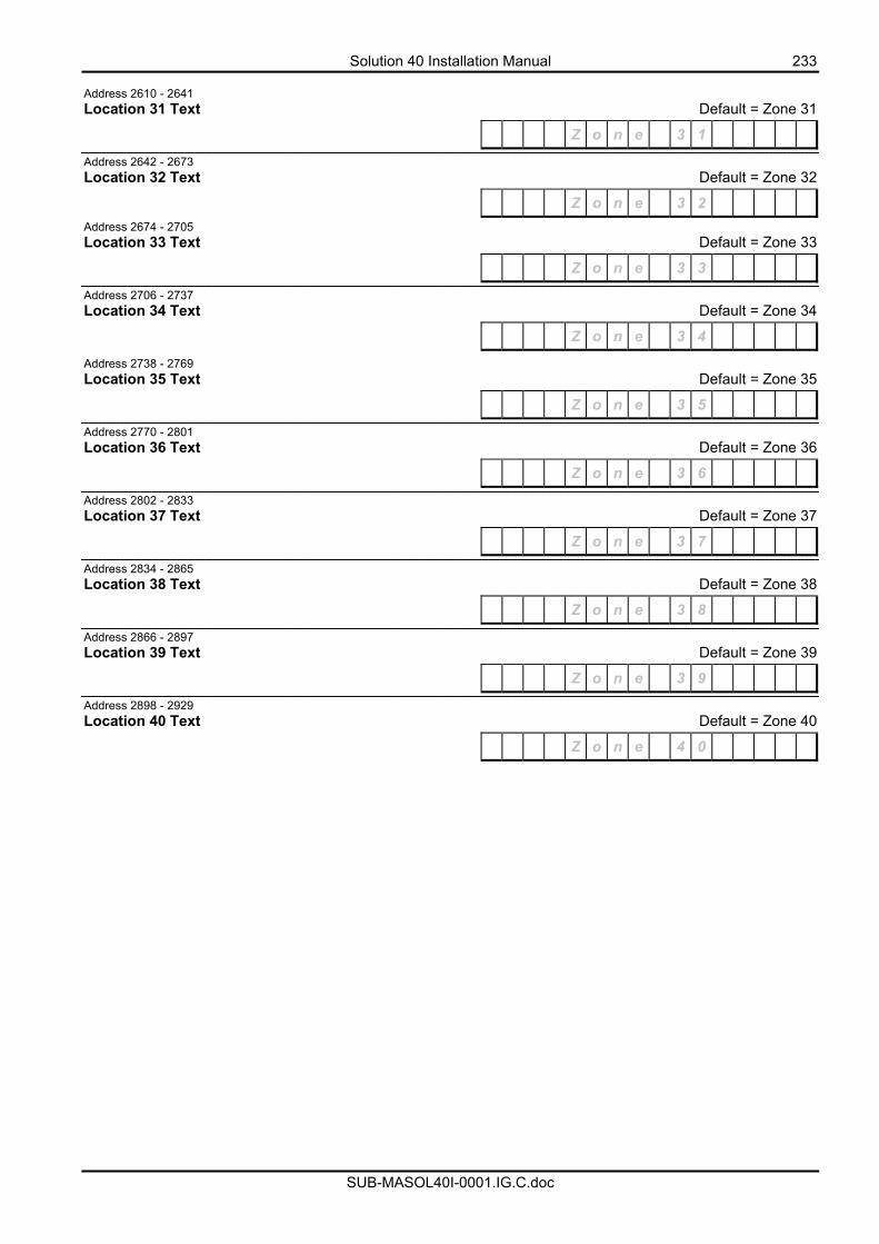
Solution 40 Installation Manual 233
SUB-MASOL40I-0001.IG.C.doc
Address 2610 - 2641 Location 31 Text Default = Zone 31
Z o n e 3 1
Address 2642 - 2673 Location 32 Text Default = Zone 32
Z o n e 3 2 Address 2674 - 2705 Location 33 Text Default = Zone 33
Z o n e 3 3
Address 2706 - 2737 Location 34 Text Default = Zone 34
Z o n e 3 4
Address 2738 - 2769 Location 35 Text Default = Zone 35
Z o n e 3 5
Address 2770 - 2801 Location 36 Text Default = Zone 36
Z o n e 3 6
Address 2802 - 2833 Location 37 Text Default = Zone 37
Z o n e 3 7
Address 2834 - 2865 Location 38 Text Default = Zone 38
Z o n e 3 8
Address 2866 - 2897 Location 39 Text Default = Zone 39
Z o n e 3 9
Address 2898 - 2929 Location 40 Text Default = Zone 40
Z o n e 4 0
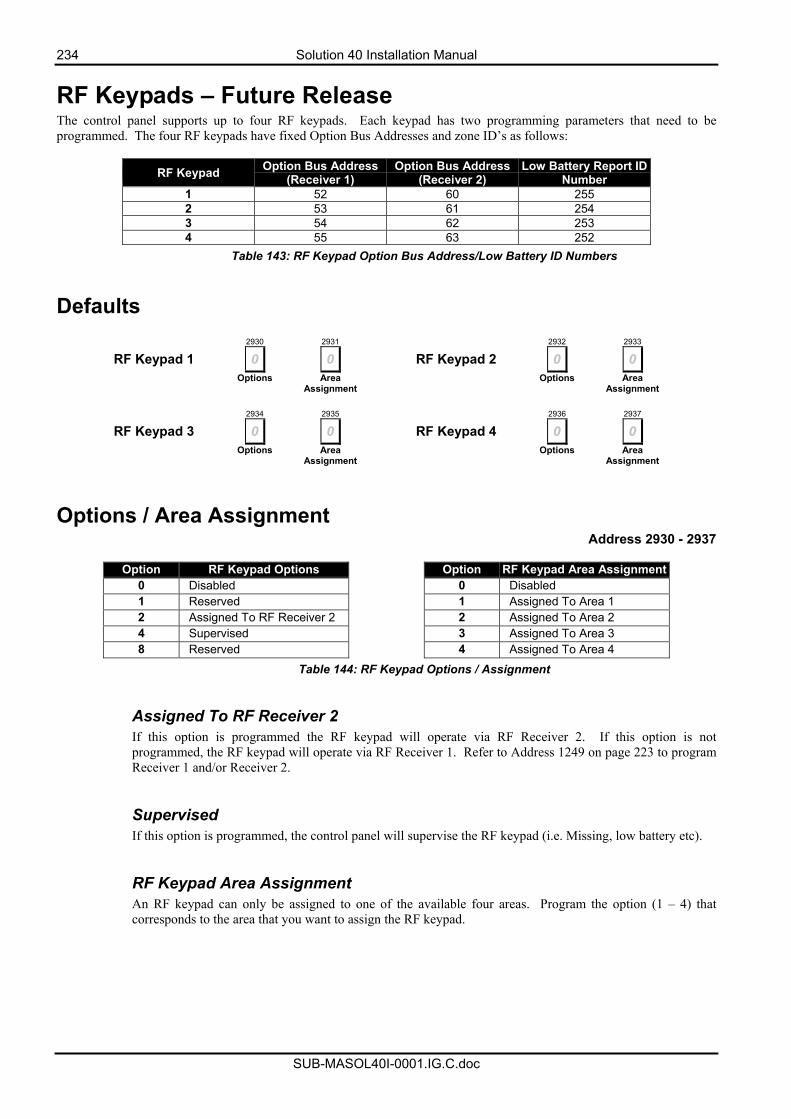
234 Solution 40 Installation Manual
SUB-MASOL40I-0001.IG.C.doc
RF Keypads – Future Release The control panel supports up to four RF keypads. Each keypad has two programming parameters that need to be programmed. The four RF keypads have fixed Option Bus Addresses and zone ID’s as follows:
RF Keypad Option Bus Address (Receiver 1)
Option Bus Address (Receiver 2)
Low Battery Report ID Number
1 52 60 255 2 53 61 254 3 54 62 253 4 55 63 252
Table 143: RF Keypad Option Bus Address/Low Battery ID Numbers
Defaults
2930 2931 2932 2933
RF Keypad 1 0 0 RF Keypad 2 0 0 Options Area
Assignment Options Area
Assignment
2934 2935 2936 2937
RF Keypad 3 0 0 RF Keypad 4 0 0 Options Area
Assignment Options Area
Assignment
Options / Area Assignment Address 2930 - 2937
Option RF Keypad Options Option RF Keypad Area Assignment
0 Disabled 0 Disabled 1 Reserved 1 Assigned To Area 1 2 Assigned To RF Receiver 2 2 Assigned To Area 2 4 Supervised 3 Assigned To Area 3 8 Reserved 4 Assigned To Area 4
Table 144: RF Keypad Options / Assignment
Assigned To RF Receiver 2 If this option is programmed the RF keypad will operate via RF Receiver 2. If this option is not programmed, the RF keypad will operate via RF Receiver 1. Refer to Address 1249 on page 223 to program Receiver 1 and/or Receiver 2. Supervised If this option is programmed, the control panel will supervise the RF keypad (i.e. Missing, low battery etc). RF Keypad Area Assignment An RF keypad can only be assigned to one of the available four areas. Program the option (1 – 4) that corresponds to the area that you want to assign the RF keypad.
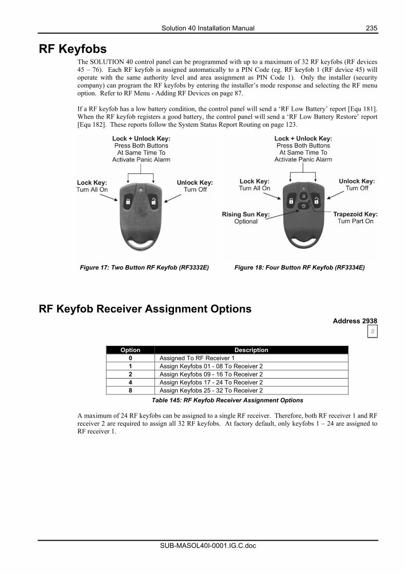
Solution 40 Installation Manual 235
SUB-MASOL40I-0001.IG.C.doc
RF Keyfobs The SOLUTION 40 control panel can be programmed with up to a maximum of 32 RF keyfobs (RF devices 45 – 76). Each RF keyfob is assigned automatically to a PIN Code (eg. RF keyfob 1 (RF device 45) will operate with the same authority level and area assignment as PIN Code 1). Only the installer (security company) can program the RF keyfobs by entering the installer’s mode response and selecting the RF menu option. Refer to RF Menu - Adding RF Devices on page 87. If a RF keyfob has a low battery condition, the control panel will send a ‘RF Low Battery’ report [Equ 181]. When the RF keyfob registers a good battery, the control panel will send a ‘RF Low Battery Restore’ report [Equ 182]. These reports follow the System Status Report Routing on page 123.
Figure 17: Two Button RF Keyfob (RF3332E) Figure 18: Four Button RF Keyfob (RF3334E)
RF Keyfob Receiver Assignment Options Address 2938
8
Option Description 0 Assigned To RF Receiver 1 1 Assign Keyfobs 01 - 08 To Receiver 2 2 Assign Keyfobs 09 - 16 To Receiver 2 4 Assign Keyfobs 17 - 24 To Receiver 2 8 Assign Keyfobs 25 - 32 To Receiver 2
Table 145: RF Keyfob Receiver Assignment Options A maximum of 24 RF keyfobs can be assigned to a single RF receiver. Therefore, both RF receiver 1 and RF receiver 2 are required to assign all 32 RF keyfobs. At factory default, only keyfobs 1 – 24 are assigned to RF receiver 1.
236 Solution 40 Installation Manual
SUB-MASOL40I-0001.IG.C.doc
RF Keyfob Options Address 2939
7
Option Description 0 No Options Programmed 1 ‘Panic’ Alarm Allowed 2 Audible Alarm Allowed For ‘Panic’ 4 Assign ‘O’ (Trapezoid) Key To Arm the System in Stay mode 8 Assign ‘P’ (Rising Sun) Key To Arm the System in Stay 2 mode
Table 146: RF Keyfob Options ‘Panic’ Alarm Allowed If this option is programmed, a ‘Panic’ alarm can be initiated by pressing both the ‘lock’ and ‘unlock’ keys simultaneously. An RF keypad panic alarm will send a ‘Duress’ report [Equ 74]. The ‘Duress’ report will follow the report routing of Address 0703 on page 175.
Audible Alarm Allowed For ‘Panic” If this option is programmed, a ‘Panic’ alarm that has been activated via an RF keyfob will sound an audible alarm. This option requires ‘Panic’ Alarm Allowed in this address programmed to operate.
Assign ‘O’ (Trapezoid) Key To Arm System in Stay Mode If this option is programmed, the trapezoid key will arm the system (or Area) in Stay mode. You can also program an output to follow the trapezoid key (Output event type 1,15) but not simultaneously. Refer to Outputs on page 204 for more information.
Assign ‘P’ (Rising Sun) Key To Arm System in Stay 2 Mode If this option is programmed, the sun key will arm the system (or Area) Stay 2. You can also program an output to follow the sun key (Output event type 2,0) but not simultaneously. Refer to Outputs on page 204 for more information.
Return To Factory Default Address 2944
0 This address allows you to reset the control panel configuration back to factory default. Program a one (1) into this address to default the panel configuration. Note: If a panel has been defaulted the current date and time settings must be entered as the default procedure clears time and date counters..
• Enter current date and time by using [Command] [4] [5]. You may be asked to enter your PIN. • Press [#] to exit.
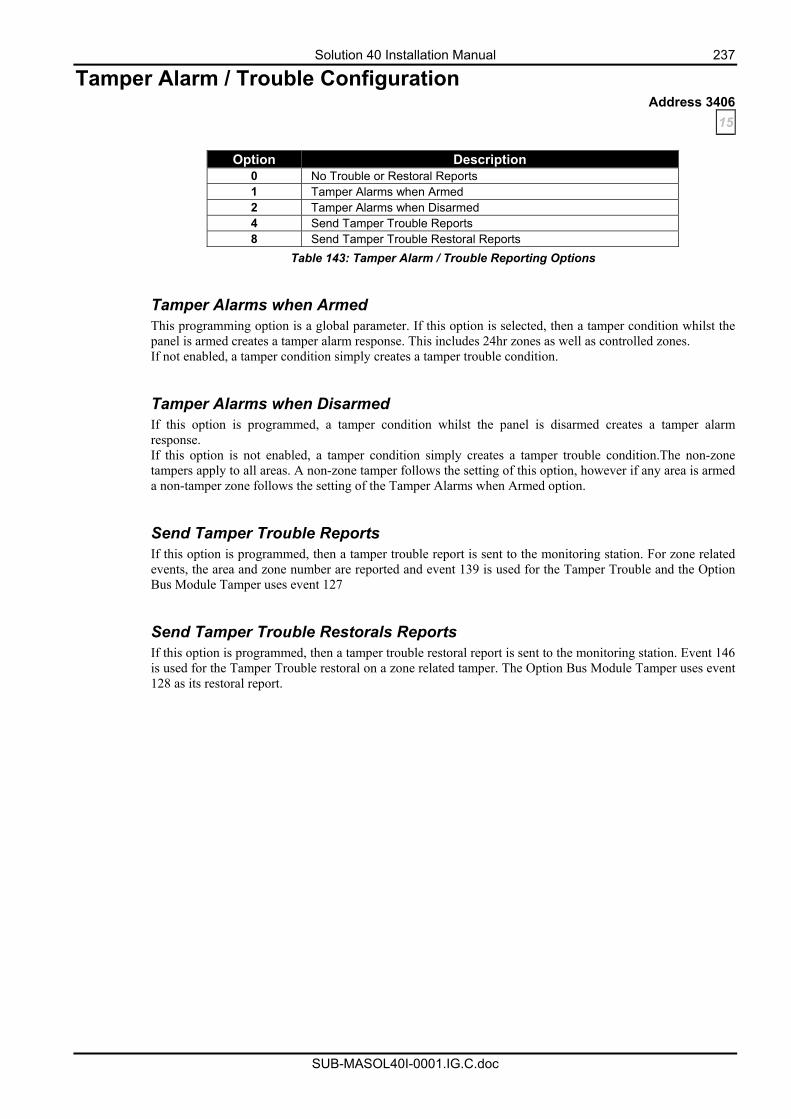
Solution 40 Installation Manual 237
SUB-MASOL40I-0001.IG.C.doc
Tamper Alarm / Trouble Configuration Address 3406
15
Option Description 0 No Trouble or Restoral Reports 1 Tamper Alarms when Armed 2 Tamper Alarms when Disarmed 4 Send Tamper Trouble Reports 8 Send Tamper Trouble Restoral Reports
Table 143: Tamper Alarm / Trouble Reporting Options Tamper Alarms when Armed This programming option is a global parameter. If this option is selected, then a tamper condition whilst the panel is armed creates a tamper alarm response. This includes 24hr zones as well as controlled zones. If not enabled, a tamper condition simply creates a tamper trouble condition.
Tamper Alarms when Disarmed If this option is programmed, a tamper condition whilst the panel is disarmed creates a tamper alarm response. If this option is not enabled, a tamper condition simply creates a tamper trouble condition.The non-zone tampers apply to all areas. A non-zone tamper follows the setting of this option, however if any area is armed a non-tamper zone follows the setting of the Tamper Alarms when Armed option.
Send Tamper Trouble Reports If this option is programmed, then a tamper trouble report is sent to the monitoring station. For zone related events, the area and zone number are reported and event 139 is used for the Tamper Trouble and the Option Bus Module Tamper uses event 127
Send Tamper Trouble Restorals Reports If this option is programmed, then a tamper trouble restoral report is sent to the monitoring station. Event 146 is used for the Tamper Trouble restoral on a zone related tamper. The Option Bus Module Tamper uses event 128 as its restoral report.
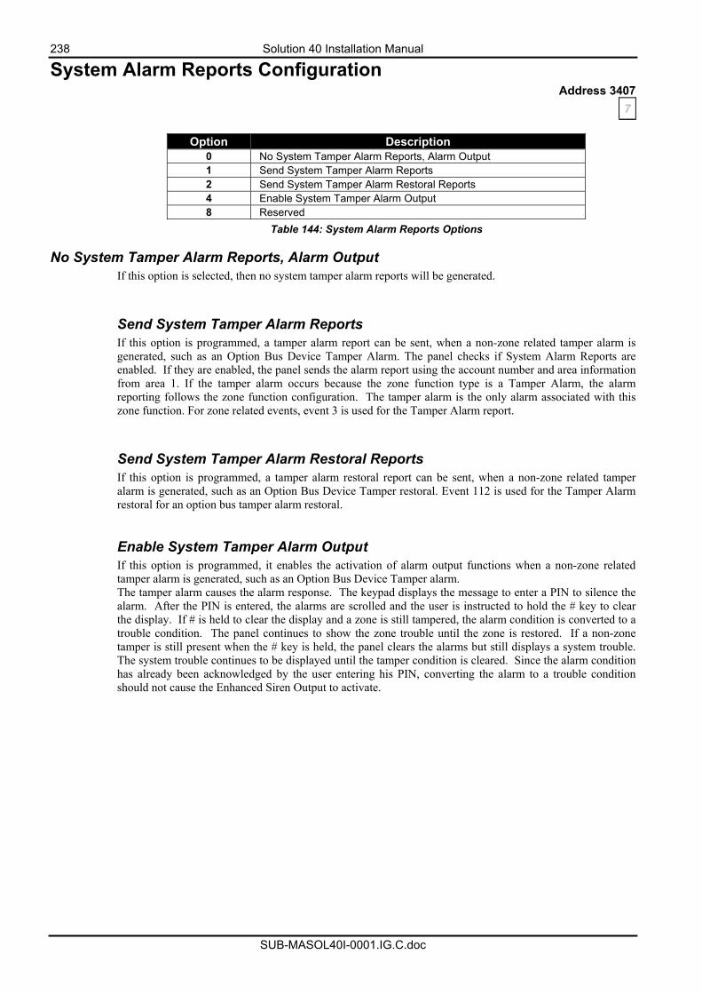
238 Solution 40 Installation Manual
SUB-MASOL40I-0001.IG.C.doc
System Alarm Reports Configuration Address 3407
7
Option Description 0 No System Tamper Alarm Reports, Alarm Output 1 Send System Tamper Alarm Reports 2 Send System Tamper Alarm Restoral Reports 4 Enable System Tamper Alarm Output 8 Reserved
Table 144: System Alarm Reports Options
No System Tamper Alarm Reports, Alarm Output If this option is selected, then no system tamper alarm reports will be generated.
Send System Tamper Alarm Reports If this option is programmed, a tamper alarm report can be sent, when a non-zone related tamper alarm is generated, such as an Option Bus Device Tamper Alarm. The panel checks if System Alarm Reports are enabled. If they are enabled, the panel sends the alarm report using the account number and area information from area 1. If the tamper alarm occurs because the zone function type is a Tamper Alarm, the alarm reporting follows the zone function configuration. The tamper alarm is the only alarm associated with this zone function. For zone related events, event 3 is used for the Tamper Alarm report.
Send System Tamper Alarm Restoral Reports If this option is programmed, a tamper alarm restoral report can be sent, when a non-zone related tamper alarm is generated, such as an Option Bus Device Tamper restoral. Event 112 is used for the Tamper Alarm restoral for an option bus tamper alarm restoral. Enable System Tamper Alarm Output If this option is programmed, it enables the activation of alarm output functions when a non-zone related tamper alarm is generated, such as an Option Bus Device Tamper alarm. The tamper alarm causes the alarm response. The keypad displays the message to enter a PIN to silence the alarm. After the PIN is entered, the alarms are scrolled and the user is instructed to hold the # key to clear the display. If # is held to clear the display and a zone is still tampered, the alarm condition is converted to a trouble condition. The panel continues to show the zone trouble until the zone is restored. If a non-zone tamper is still present when the # key is held, the panel clears the alarms but still displays a system trouble. The system trouble continues to be displayed until the tamper condition is cleared. Since the alarm condition has already been acknowledged by the user entering his PIN, converting the alarm to a trouble condition should not cause the Enhanced Siren Output to activate.
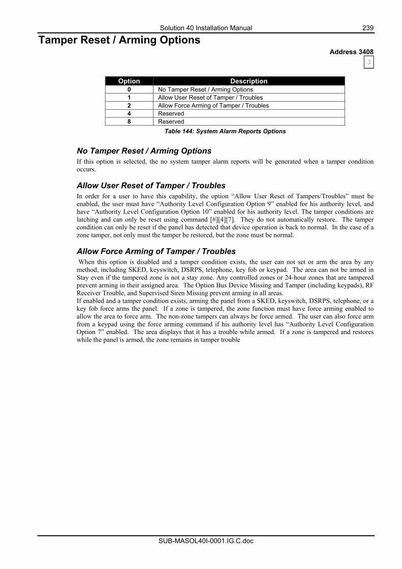
Solution 40 Installation Manual 239
SUB-MASOL40I-0001.IG.C.doc
Tamper Reset / Arming Options Address 3408
3
Option Description 0 No Tamper Reset / Arming Options 1 Allow User Reset of Tamper / Troubles 2 Allow Force Arming of Tamper / Troubles 4 Reserved 8 Reserved
Table 144: System Alarm Reports Options No Tamper Reset / Arming Options If this option is selected, the no system tamper alarm reports will be generated when a tamper condition occurs.
Allow User Reset of Tamper / Troubles In order for a user to have this capability, the option “Allow User Reset of Tampers/Troubles” must be enabled, the user must have “Authority Level Configuration Option 9” enabled for his authority level, and have “Authority Level Configuration Option 10” enabled for his authority level. The tamper conditions are latching and can only be reset using command [#][4][7]. They do not automatically restore. The tamper condition can only be reset if the panel has detected that device operation is back to normal. In the case of a zone tamper, not only must the tamper be restored, but the zone must be normal.
Allow Force Arming of Tamper / Troubles When this option is disabled and a tamper condition exists, the user can not set or arm the area by any method, including SKED, keyswitch, DSRPS, telephone, key fob or keypad. The area can not be armed in Stay even if the tampered zone is not a stay zone. Any controlled zones or 24-hour zones that are tampered prevent arming in their assigned area. The Option Bus Device Missing and Tamper (including keypads), RF Receiver Trouble, and Supervised Siren Missing prevent arming in all areas. If enabled and a tamper condition exists, arming the panel from a SKED, keyswitch, DSRPS, telephone, or a key fob force arms the panel. If a zone is tampered, the zone function must have force arming enabled to allow the area to force arm. The non-zone tampers can always be force armed. The user can also force arm from a keypad using the force arming command if his authority level has “Authority Level Configuration Option 7” enabled. The area displays that it has a trouble while armed. If a zone is tampered and restores while the panel is armed, the zone remains in tamper trouble
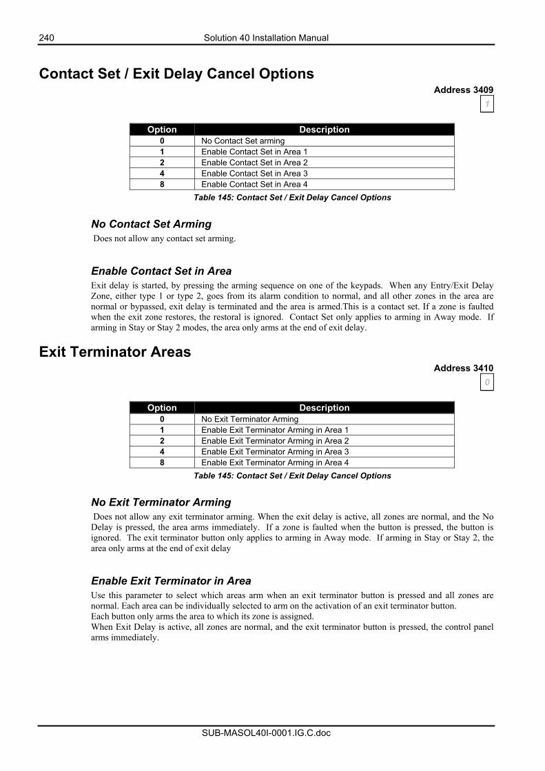
240 Solution 40 Installation Manual
SUB-MASOL40I-0001.IG.C.doc
Contact Set / Exit Delay Cancel Options
Address 3409 1
Option Description
0 No Contact Set arming 1 Enable Contact Set in Area 1 2 Enable Contact Set in Area 2 4 Enable Contact Set in Area 3 8 Enable Contact Set in Area 4
Table 145: Contact Set / Exit Delay Cancel Options No Contact Set Arming Does not allow any contact set arming.
Enable Contact Set in Area Exit delay is started, by pressing the arming sequence on one of the keypads. When any Entry/Exit Delay Zone, either type 1 or type 2, goes from its alarm condition to normal, and all other zones in the area are normal or bypassed, exit delay is terminated and the area is armed.This is a contact set. If a zone is faulted when the exit zone restores, the restoral is ignored. Contact Set only applies to arming in Away mode. If arming in Stay or Stay 2 modes, the area only arms at the end of exit delay.
Exit Terminator Areas Address 3410
0
Option Description 0 No Exit Terminator Arming 1 Enable Exit Terminator Arming in Area 1 2 Enable Exit Terminator Arming in Area 2 4 Enable Exit Terminator Arming in Area 3 8 Enable Exit Terminator Arming in Area 4
Table 145: Contact Set / Exit Delay Cancel Options No Exit Terminator Arming Does not allow any exit terminator arming. When the exit delay is active, all zones are normal, and the No Delay is pressed, the area arms immediately. If a zone is faulted when the button is pressed, the button is ignored. The exit terminator button only applies to arming in Away mode. If arming in Stay or Stay 2, the area only arms at the end of exit delay
Enable Exit Terminator in Area Use this parameter to select which areas arm when an exit terminator button is pressed and all zones are normal. Each area can be individually selected to arm on the activation of an exit terminator button. Each button only arms the area to which its zone is assigned. When Exit Delay is active, all zones are normal, and the exit terminator button is pressed, the control panel arms immediately.
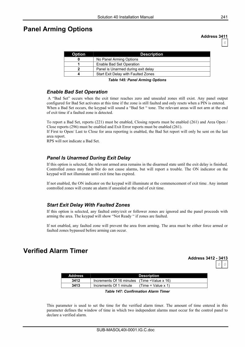
Solution 40 Installation Manual 241
SUB-MASOL40I-0001.IG.C.doc
Panel Arming Options Address 3411
6
Option Description 0 No Panel Arming Options 1 Enable Bad Set Operation 2 Panel is Unarmed during exit delay 4 Start Exit Delay with Faulted Zones
Table 145: Panel Arming Options Enable Bad Set Operation A “Bad Set” occurs when the exit timer reaches zero and unsealed zones still exist. Any panel output configured for Bad Set activates at this time if the zone is still faulted and only resets when a PIN is entered. When a Bad Set occurs, the keypad will sound a “Bad Set “ tone. The relevant areas will not arm at the end of exit time if a faulted zone is detected. To report a Bad Set, reports (221) must be enabled, Closing reports must be enabled (261) and Area Open / Close reports (296) must be enabled and Exit Error reports must be enabled (261). If First to Open/ Last to Close for area reporting is enabled, the Bad Set report will only be sent on the last area report. RPS will not indicate a Bad Set.
Panel Is Unarmed During Exit Delay If this option is selected, the relevant armed area remains in the disarmed state until the exit delay is finished. Controlled zones may fault but do not cause alarms, but will report a trouble. The ON indicator on the keypad will not illuminate until exit time has expired. If not enabled, the ON indicator on the keypad will illuminate at the commencement of exit time. Any instant controlled zones will create an alarm if unsealed at the end of exit time.
Start Exit Delay With Faulted Zones If this option is selected, any faulted entry/exit or follower zones are ignored and the panel proceeds with arming the area. The keypad will show “Not Ready “ if zones are faulted. If not enabled, any faulted zone will prevent the area from arming. The area must be either force armed or faulted zones bypassed before arming can occur.
Verified Alarm Timer Address 3412 - 3413
0 0
Address Description 3412 Increments Of 16 minutes (Time =Value x 16) 3413 Increments Of 1 minute (Time = Value x 1)
Table 147: Confirmation Alarm Timer
This parameter is used to set the time for the verified alarm timer. The amount of time entered in this parameter defines the window of time in which two independent alarms must occur for the control panel to declare a verified alarm.
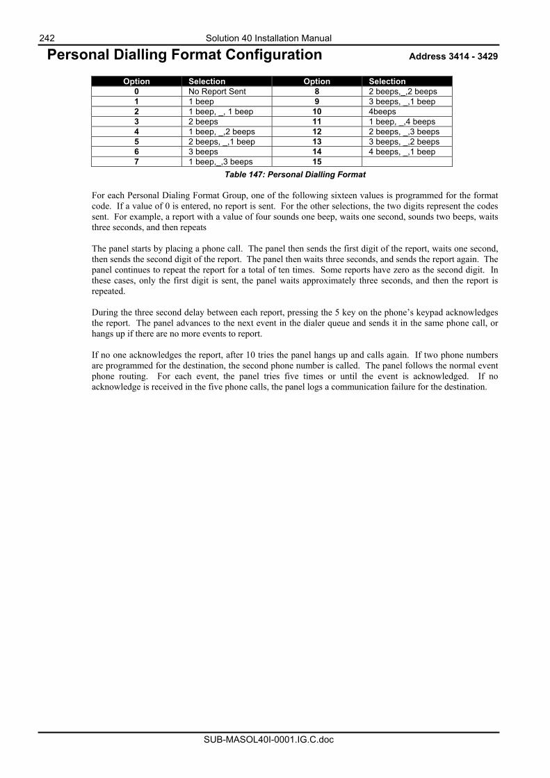
242 Solution 40 Installation Manual
SUB-MASOL40I-0001.IG.C.doc
Personal Dialling Format Configuration Address 3414 - 3429
Option Selection Option Selection 0 No Report Sent 8 2 beeps,_,2 beeps 1 1 beep 9 3 beeps, _,1 beep 2 1 beep, _, 1 beep 10 4beeps 3 2 beeps 11 1 beep, _,4 beeps 4 1 beep, _,2 beeps 12 2 beeps, _,3 beeps 5 2 beeps, _,1 beep 13 3 beeps, _,2 beeps 6 3 beeps 14 4 beeps, _,1 beep 7 1 beep,_,3 beeps 15
Table 147: Personal Dialling Format For each Personal Dialing Format Group, one of the following sixteen values is programmed for the format code. If a value of 0 is entered, no report is sent. For the other selections, the two digits represent the codes sent. For example, a report with a value of four sounds one beep, waits one second, sounds two beeps, waits three seconds, and then repeats The panel starts by placing a phone call. The panel then sends the first digit of the report, waits one second, then sends the second digit of the report. The panel then waits three seconds, and sends the report again. The panel continues to repeat the report for a total of ten times. Some reports have zero as the second digit. In these cases, only the first digit is sent, the panel waits approximately three seconds, and then the report is repeated. During the three second delay between each report, pressing the 5 key on the phone’s keypad acknowledges the report. The panel advances to the next event in the dialer queue and sends it in the same phone call, or hangs up if there are no more events to report. If no one acknowledges the report, after 10 tries the panel hangs up and calls again. If two phone numbers are programmed for the destination, the second phone number is called. The panel follows the normal event phone routing. For each event, the panel tries five times or until the event is acknowledged. If no acknowledge is received in the five phone calls, the panel logs a communication failure for the destination.
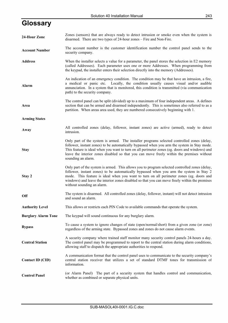
Solution 40 Installation Manual 243
SUB-MASOL40I-0001.IG.C.doc
Glossary
24-Hour Zone Zones (sensors) that are always ready to detect intrusion or smoke even when the system is disarmed. There are two types of 24-hour zones – Fire and Non-Fire.
Account Number The account number is the customer identification number the control panel sends to the security company.
Address When the installer selects a value for a parameter, the panel stores the selection in E2 memory
(called Addresses). Each parameter uses one or more Addresses. When programming from the keypad, the installer enters their selection directly into the memory (Addresses).
Alarm
An indication of an emergency condition. The condition may be that have an intrusion, a fire, a medical or panic etc. Locally, the condition usually causes visual and/or audible annunciation. In a system that is monitored, this condition is transmitted (via communication path) to the security company.
Area The control panel can be split (divided) up to a maximum of four independent areas. A defines section that can be armed and disarmed independently. This is sometimes also referred to as a partition. When areas area used, they are numbered consecutively beginning with 1.
Arming States
Away All controlled zones (delay, follower, instant zones) are active (armed), ready to detect intrusion.
Stay
Only part of the system is armed. The installer programs selected controlled zones (delay, follower, instant zones) to be automatically bypassed when you arm the system in Stay mode. This feature is ideal when you want to turn on all perimeter zones (eg. doors and windows) and leave the interior zones disabled so that you can move freely within the premises without sounding an alarm.
Stay 2
Only part of the system is armed. This allows you to program selected controlled zones (delay, follower, instant zones) to be automatically bypassed when you arm the system in Stay 2mode. This feature is ideal when you want to turn on all perimeter zones (eg. doors and windows) and leave the interior zones disabled so that you can move freely within the premises without sounding an alarm.
Off The system is disarmed. All controlled zones (delay, follower, instant) will not detect intrusion and sound an alarm.
Authority Level This allows or restricts each PIN Code to available commands that operate the system. Burglary Alarm Tone The keypad will sound continuous for any burglary alarm.
Bypass To cause a system to ignore changes of state (open/normal/short) from a given zone (or zone) regardless of the arming state. Bypassed zones and zones do not cause alarm events.
Central Station A security company where trained staff monitor many security control panels 24-hours a day. The control panel may be programmed to report to the central station during alarm conditions, allowing staff to dispatch the appropriate authorities to respond.
Contact ID (CID) A communication format that the control panel uses to communicate to the security company’s central station receiver that utilizes a set of standard DTMF tones for transmission of information.
Control Panel (or Alarm Panel) The part of a security system that handles control and communication, whether as combined or separate physical units.
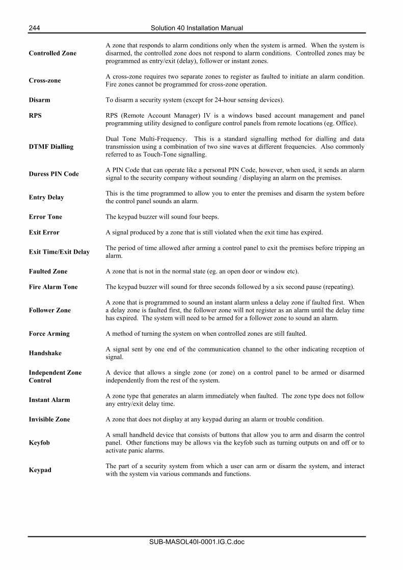
244 Solution 40 Installation Manual
SUB-MASOL40I-0001.IG.C.doc
Controlled Zone A zone that responds to alarm conditions only when the system is armed. When the system is disarmed, the controlled zone does not respond to alarm conditions. Controlled zones may be programmed as entry/exit (delay), follower or instant zones.
Cross-zone A cross-zone requires two separate zones to register as faulted to initiate an alarm condition. Fire zones cannot be programmed for cross-zone operation.
Disarm To disarm a security system (except for 24-hour sensing devices). RPS RPS (Remote Account Manager) IV is a windows based account management and panel
programming utility designed to configure control panels from remote locations (eg. Office).
DTMF Dialling Dual Tone Multi-Frequency. This is a standard signalling method for dialling and data transmission using a combination of two sine waves at different frequencies. Also commonly referred to as Touch-Tone signalling.
Duress PIN Code A PIN Code that can operate like a personal PIN Code, however, when used, it sends an alarm signal to the security company without sounding / displaying an alarm on the premises.
Entry Delay This is the time programmed to allow you to enter the premises and disarm the system before the control panel sounds an alarm.
Error Tone The keypad buzzer will sound four beeps. Exit Error A signal produced by a zone that is still violated when the exit time has expired.
Exit Time/Exit Delay The period of time allowed after arming a control panel to exit the premises before tripping an alarm.
Faulted Zone A zone that is not in the normal state (eg. an open door or window etc). Fire Alarm Tone The keypad buzzer will sound for three seconds followed by a six second pause (repeating).
Follower Zone A zone that is programmed to sound an instant alarm unless a delay zone if faulted first. When a delay zone is faulted first, the follower zone will not register as an alarm until the delay time has expired. The system will need to be armed for a follower zone to sound an alarm.
Force Arming A method of turning the system on when controlled zones are still faulted.
Handshake A signal sent by one end of the communication channel to the other indicating reception of signal.
Independent Zone Control
A device that allows a single zone (or zone) on a control panel to be armed or disarmed independently from the rest of the system.
Instant Alarm A zone type that generates an alarm immediately when faulted. The zone type does not follow any entry/exit delay time.
Invisible Zone A zone that does not display at any keypad during an alarm or trouble condition.
Keyfob A small handheld device that consists of buttons that allow you to arm and disarm the control panel. Other functions may be allows via the keyfob such as turning outputs on and off or to activate panic alarms.
Keypad The part of a security system from which a user can arm or disarm the system, and interact with the system via various commands and functions.
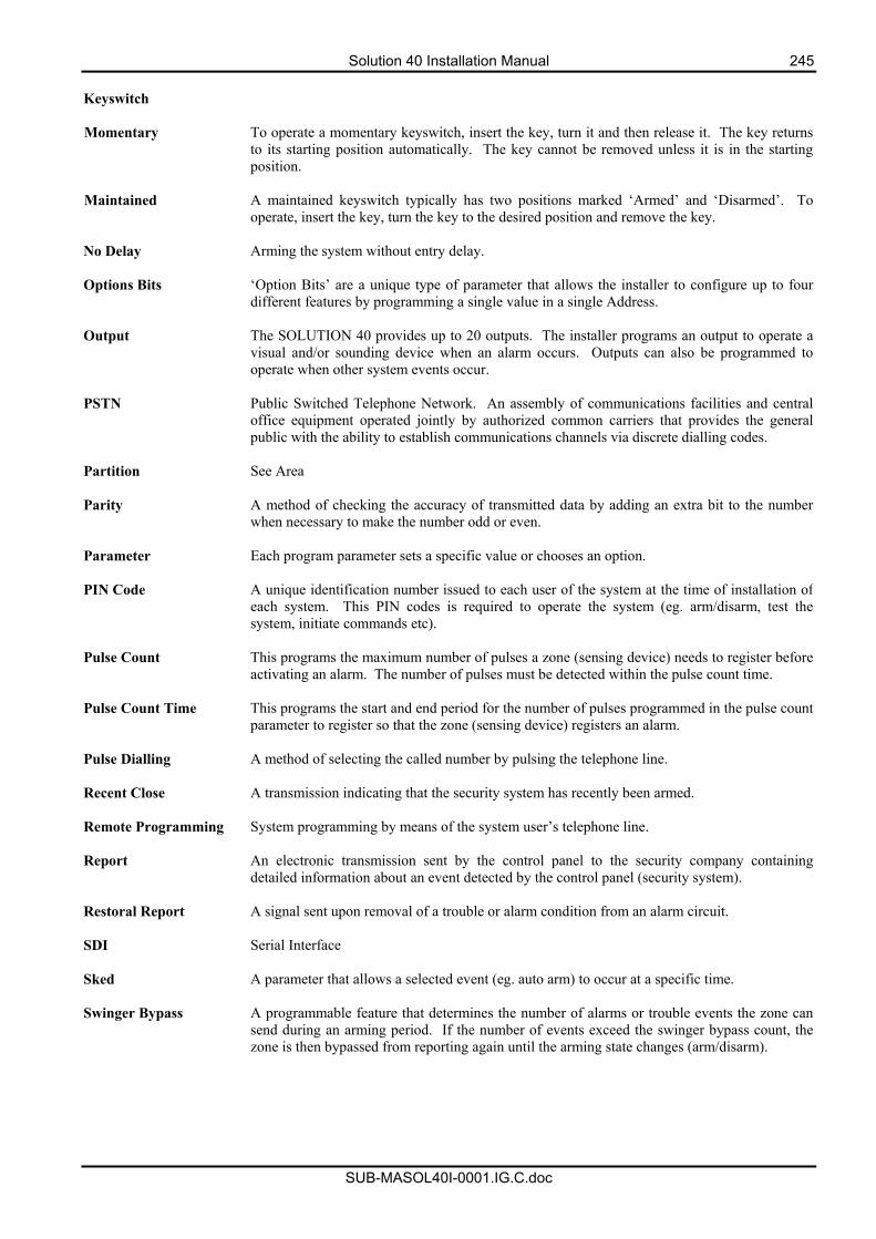
Solution 40 Installation Manual 245
SUB-MASOL40I-0001.IG.C.doc
Keyswitch Momentary To operate a momentary keyswitch, insert the key, turn it and then release it. The key returns
to its starting position automatically. The key cannot be removed unless it is in the starting position.
Maintained A maintained keyswitch typically has two positions marked ‘Armed’ and ‘Disarmed’. To
operate, insert the key, turn the key to the desired position and remove the key. No Delay Arming the system without entry delay. Options Bits ‘Option Bits’ are a unique type of parameter that allows the installer to configure up to four
different features by programming a single value in a single Address. Output The SOLUTION 40 provides up to 20 outputs. The installer programs an output to operate a
visual and/or sounding device when an alarm occurs. Outputs can also be programmed to operate when other system events occur.
PSTN Public Switched Telephone Network. An assembly of communications facilities and central
office equipment operated jointly by authorized common carriers that provides the general public with the ability to establish communications channels via discrete dialling codes.
Partition See Area Parity A method of checking the accuracy of transmitted data by adding an extra bit to the number
when necessary to make the number odd or even. Parameter Each program parameter sets a specific value or chooses an option. PIN Code A unique identification number issued to each user of the system at the time of installation of
each system. This PIN codes is required to operate the system (eg. arm/disarm, test the system, initiate commands etc).
Pulse Count This programs the maximum number of pulses a zone (sensing device) needs to register before
activating an alarm. The number of pulses must be detected within the pulse count time. Pulse Count Time This programs the start and end period for the number of pulses programmed in the pulse count
parameter to register so that the zone (sensing device) registers an alarm. Pulse Dialling A method of selecting the called number by pulsing the telephone line. Recent Close A transmission indicating that the security system has recently been armed. Remote Programming System programming by means of the system user’s telephone line. Report An electronic transmission sent by the control panel to the security company containing
detailed information about an event detected by the control panel (security system). Restoral Report A signal sent upon removal of a trouble or alarm condition from an alarm circuit. SDI Serial Interface Sked A parameter that allows a selected event (eg. auto arm) to occur at a specific time. Swinger Bypass A programmable feature that determines the number of alarms or trouble events the zone can
send during an arming period. If the number of events exceed the swinger bypass count, the zone is then bypassed from reporting again until the arming state changes (arm/disarm).
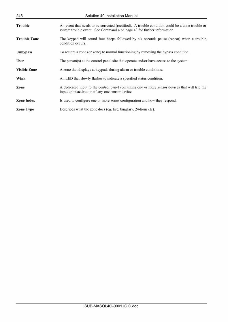
246 Solution 40 Installation Manual
SUB-MASOL40I-0001.IG.C.doc
Trouble An event that needs to be corrected (rectified). A trouble condition could be a zone trouble or
system trouble event. See Command 4 on page 43 for further information. Trouble Tone The keypad will sound four beeps followed by six seconds pause (repeat) when a trouble
condition occurs. Unbypass To restore a zone (or zone) to normal functioning by removing the bypass condition. User The person(s) at the control panel site that operate and/or have access to the system. Visible Zone A zone that displays at keypads during alarm or trouble conditions. Wink An LED that slowly flashes to indicate a specified status condition. Zone A dedicated input to the control panel containing one or more sensor devices that will trip the
input upon activation of any one-sensor device Zone Index Is used to configure one or more zones configuration and how they respond. Zone Type Describes what the zone does (eg. fire, burglary, 24-hour etc).
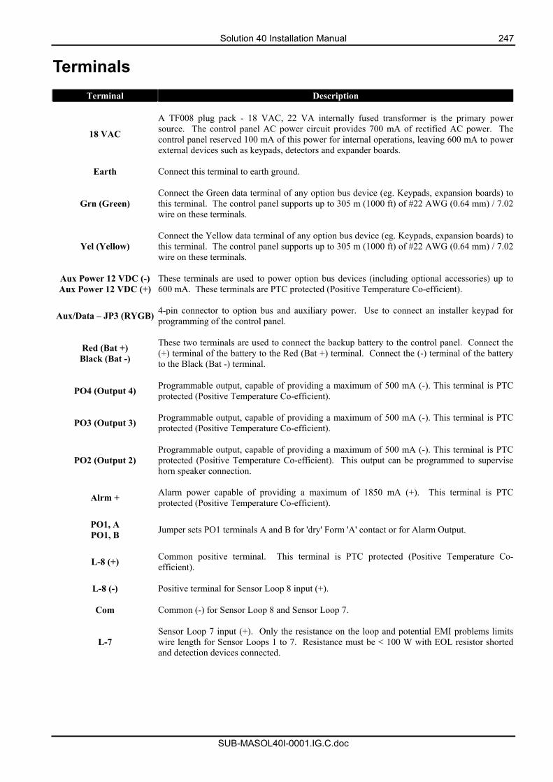
Solution 40 Installation Manual 247
SUB-MASOL40I-0001.IG.C.doc
Terminals
Terminal Description
18 VAC
A TF008 plug pack - 18 VAC, 22 VA internally fused transformer is the primary power source. The control panel AC power circuit provides 700 mA of rectified AC power. The control panel reserved 100 mA of this power for internal operations, leaving 600 mA to power external devices such as keypads, detectors and expander boards.
Earth Connect this terminal to earth ground.
Grn (Green) Connect the Green data terminal of any option bus device (eg. Keypads, expansion boards) to this terminal. The control panel supports up to 305 m (1000 ft) of #22 AWG (0.64 mm) / 7.02 wire on these terminals.
Yel (Yellow) Connect the Yellow data terminal of any option bus device (eg. Keypads, expansion boards) to this terminal. The control panel supports up to 305 m (1000 ft) of #22 AWG (0.64 mm) / 7.02 wire on these terminals.
Aux Power 12 VDC (-) Aux Power 12 VDC (+)
These terminals are used to power option bus devices (including optional accessories) up to 600 mA. These terminals are PTC protected (Positive Temperature Co-efficient).
Aux/Data – JP3 (RYGB) 4-pin connector to option bus and auxiliary power. Use to connect an installer keypad for programming of the control panel.
Red (Bat +) Black (Bat -)
These two terminals are used to connect the backup battery to the control panel. Connect the (+) terminal of the battery to the Red (Bat +) terminal. Connect the (-) terminal of the battery to the Black (Bat -) terminal.
PO4 (Output 4) Programmable output, capable of providing a maximum of 500 mA (-). This terminal is PTC protected (Positive Temperature Co-efficient).
PO3 (Output 3) Programmable output, capable of providing a maximum of 500 mA (-). This terminal is PTC protected (Positive Temperature Co-efficient).
PO2 (Output 2) Programmable output, capable of providing a maximum of 500 mA (-). This terminal is PTC protected (Positive Temperature Co-efficient). This output can be programmed to supervise horn speaker connection.
Alrm + Alarm power capable of providing a maximum of 1850 mA (+). This terminal is PTC protected (Positive Temperature Co-efficient).
PO1, A PO1, B Jumper sets PO1 terminals A and B for 'dry' Form 'A' contact or for Alarm Output.
L-8 (+) Common positive terminal. This terminal is PTC protected (Positive Temperature Co-efficient).
L-8 (-) Positive terminal for Sensor Loop 8 input (+).
Com Common (-) for Sensor Loop 8 and Sensor Loop 7.
L-7 Sensor Loop 7 input (+). Only the resistance on the loop and potential EMI problems limits wire length for Sensor Loops 1 to 7. Resistance must be < 100 W with EOL resistor shorted and detection devices connected.
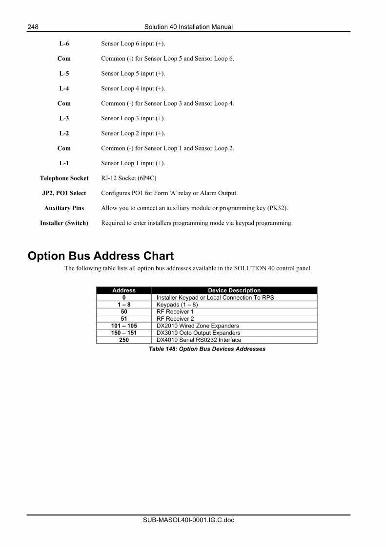
248 Solution 40 Installation Manual
SUB-MASOL40I-0001.IG.C.doc
L-6 Sensor Loop 6 input (+).
Com Common (-) for Sensor Loop 5 and Sensor Loop 6.
L-5 Sensor Loop 5 input (+).
L-4 Sensor Loop 4 input (+).
Com Common (-) for Sensor Loop 3 and Sensor Loop 4.
L-3 Sensor Loop 3 input (+).
L-2 Sensor Loop 2 input (+).
Com Common (-) for Sensor Loop 1 and Sensor Loop 2.
L-1 Sensor Loop 1 input (+).
Telephone Socket RJ-12 Socket (6P4C)
JP2, PO1 Select Configures PO1 for Form 'A' relay or Alarm Output.
Auxiliary Pins Allow you to connect an auxiliary module or programming key (PK32).
Installer (Switch) Required to enter installers programming mode via keypad programming.
Option Bus Address Chart The following table lists all option bus addresses available in the SOLUTION 40 control panel.
Address Device Description 0 Installer Keypad or Local Connection To RPS
1 – 8 Keypads (1 – 8) 50 RF Receiver 1 51 RF Receiver 2
101 – 105 DX2010 Wired Zone Expanders 150 – 151 DX3010 Octo Output Expanders
250 DX4010 Serial RS0232 Interface Table 148: Option Bus Devices Addresses
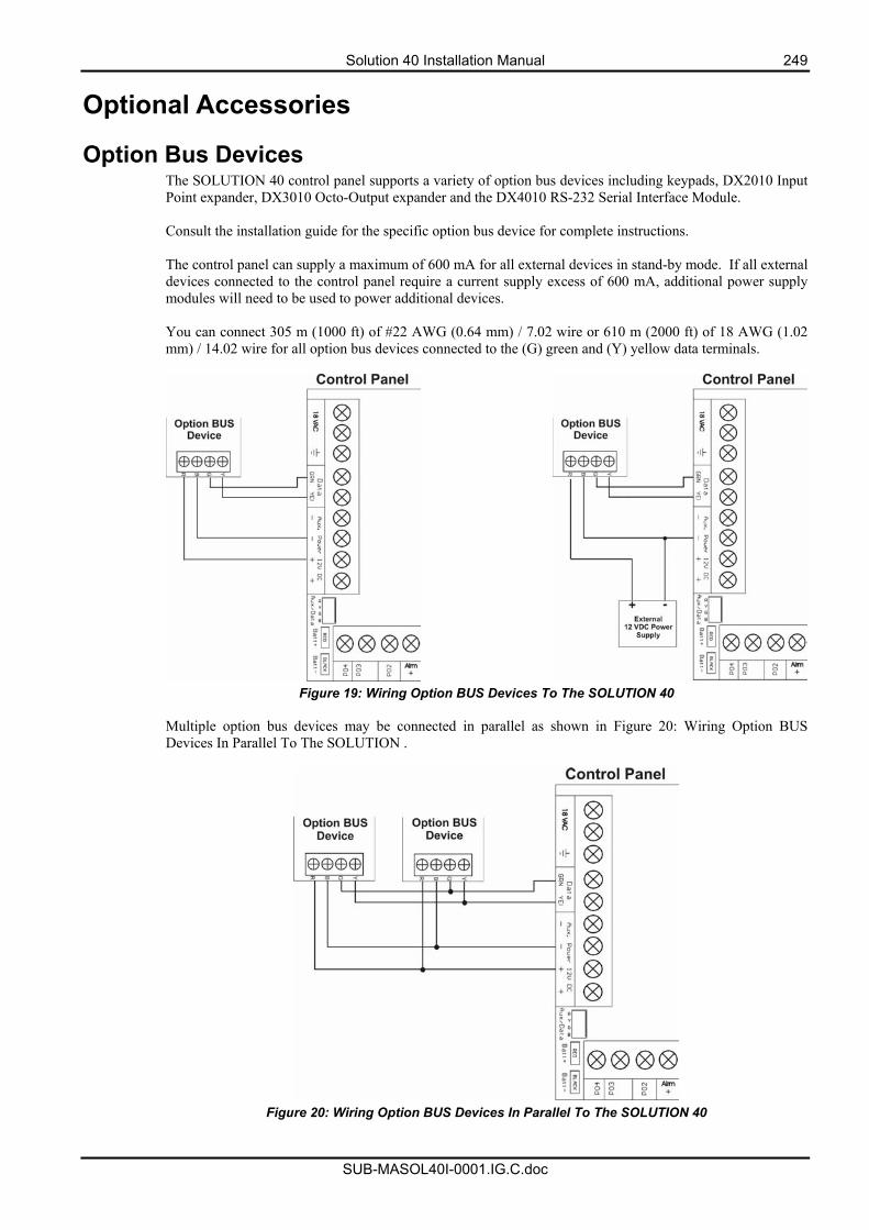
Solution 40 Installation Manual 249
SUB-MASOL40I-0001.IG.C.doc
Optional Accessories
Option Bus Devices The SOLUTION 40 control panel supports a variety of option bus devices including keypads, DX2010 Input Point expander, DX3010 Octo-Output expander and the DX4010 RS-232 Serial Interface Module. Consult the installation guide for the specific option bus device for complete instructions. The control panel can supply a maximum of 600 mA for all external devices in stand-by mode. If all external devices connected to the control panel require a current supply excess of 600 mA, additional power supply modules will need to be used to power additional devices. You can connect 305 m (1000 ft) of #22 AWG (0.64 mm) / 7.02 wire or 610 m (2000 ft) of 18 AWG (1.02 mm) / 14.02 wire for all option bus devices connected to the (G) green and (Y) yellow data terminals.
Figure 19: Wiring Option BUS Devices To The SOLUTION 40
Multiple option bus devices may be connected in parallel as shown in Figure 20: Wiring Option BUS Devices In Parallel To The SOLUTION .
Figure 20: Wiring Option BUS Devices In Parallel To The SOLUTION 40
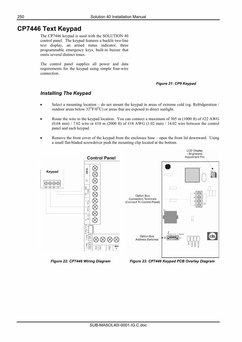
250 Solution 40 Installation Manual
SUB-MASOL40I-0001.IG.C.doc
CP7446 Text Keypad The CP7446 keypad is used with the SOLUTION 40 control panel. The keypad features a backlit two-line text display, an armed status indicator, three programmable emergency keys, built-in buzzer that emits several distinct tones. The control panel supplies all power and data requirements for the keypad using simple four-wire connection.
Figure 21: CP9 Keypad
Installing The Keypad
• Select a mounting location – do not mount the keypad in areas of extreme cold (eg. Refridgeration / outdoor areas below 32OF/0OC) or areas that are exposed to direct sunlight.
• Route the wire to the keypad location. You can connect a maximum of 305 m (1000 ft) of #22 AWG
(0.64 mm) / 7.02 wire or 610 m (2000 ft) of #18 AWG (1.02 mm) / 14.02 wire between the control panel and each keypad.
• Remove the front cover of the keypad from the enclosure base – open the front lid downward. Using
a small flat-bladed screwdriver push the mounting clip located at the bottom.
Figure 22: CP7446 Wiring Diagram Figure 23: CP7446 Keypad PCB Overlay Diagram
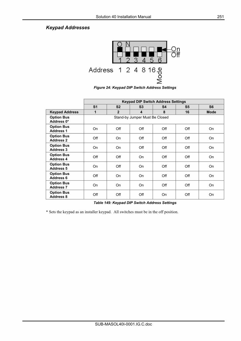
Solution 40 Installation Manual 251
SUB-MASOL40I-0001.IG.C.doc
Keypad Addresses
Figure 24: Keypad DIP Switch Address Settings
Keypad DIP Switch Address Settings S1 S2 S3 S4 S5 S6
Keypad Address 1 2 4 8 16 Mode Option Bus Address 0*
Stand-by Jumper Must Be Closed
Option Bus Address 1 On Off Off Off Off On
Option Bus Address 2 Off On Off Off Off On
Option Bus Address 3 On On Off Off Off On
Option Bus Address 4 Off Off On Off Off On
Option Bus Address 5 On Off On Off Off On
Option Bus Address 6 Off On On Off Off On
Option Bus Address 7 On On On Off Off On
Option Bus Address 8 Off Off Off On Off On
Table 149: Keypad DIP Switch Address Settings
* Sets the keypad as an installer keypad. All switches must be in the off position.
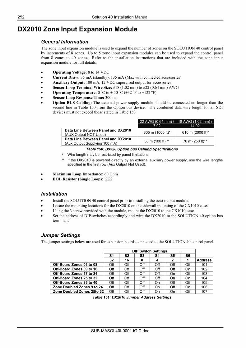
252 Solution 40 Installation Manual
SUB-MASOL40I-0001.IG.C.doc
DX2010 Zone Input Expansion Module
General Information The zone input expansion module is used to expand the number of zones on the SOLUTION 40 control panel by increments of 8 zones. Up to 5 zone input expansion modules can be used to expand the control panel from 8 zones to 40 zones. Refer to the installation instructions that are included with the zone input expansion module for full details. • Operating Voltage: 8 to 14 VDC • Current Draw: 35 mA (standby), 135 mA (Max with connected accessories) • Auxiliary Output: 100 mA, 12 VDC supervised output for accessories • Sensor Loop Terminal Wire Size: #18 (1.02 mm) to #22 (0.64 mm) AWG • Operating Temperature: 0 oC to + 50 oC (+32 oF to +122 oF) • Sensor Loop Response Time: 300 ms • Option BUS Cabling: The external power supply module should be connected no longer than the
second line in Table 150 from the Option bus device. The combined data wire length for all SDI devices must not exceed those stated in Table 150.
22 AWG (0.64 mm) /
7.02 18 AWG (1.02 mm) /
14.02 Data Line Between Panel and DX2010 (AUX Output NOT Used) 305 m (1000 ft)* 610 m (2000 ft)*
Data Line Between Panel and DX2010 (Aux Output Supplying 100 mA) 30 m (100 ft) ** 76 m (250 ft)**
Table 150: D9528 Option bus Cabling Specifications * Wire length may be restricted by panel limitations. ** If the DX2010 is powered directly by an external auxiliary power supply, use the wire lengths
specified in the first row (Aux Output Not Used).
• Maximum Loop Impedance: 60 Ohm • EOL Resistor (Single Loop): 2K2
Installation • Install the SOLUTION 40 control panel prior to installing the octo-output module. • Locate the mounting locations for the DX2010 on the sidewall mounting of the CX1010 case. • Using the 3 screw provided with the module, mount the DX2010 to the CX1010 case. • Set the address of DIP-switches accordingly and wire the DX2010 to the SOLUTION 40 option bus
terminals.
Jumper Settings The jumper settings below are used for expansion boards connected to the SOLUTION 40 control panel.
DIP Switch Settings S1 S2 S3 S4 S5 S6 32 16 8 4 2 1 Address
Off-Board Zones 01 to 08 Off Off Off Off Off Off 101 Off-Board Zones 09 to 16 Off Off Off Off Off On 102 Off-Board Zones 17 to 24 Off Off Off Off On Off 103 Off-Board Zones 25 to 32 Off Off Off Off On On 104 Off-Board Zones 33 to 40 Off Off Off On Off Off 105 Zone Doubled Zones 9 to 24 Off Off Off On Off On 106 Zone Doubled Zones 25to 32 Off Off Off On On Off 107
Table 151: DX2010 Jumper Address Settings
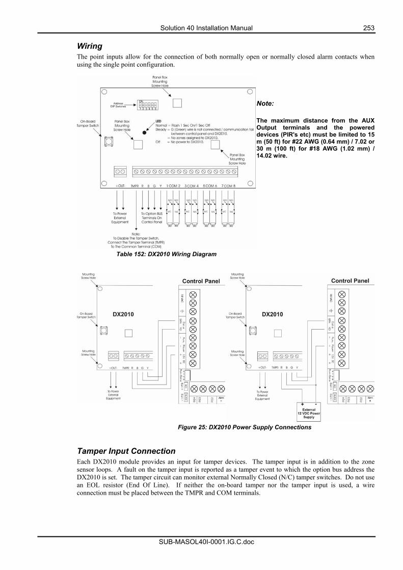
Solution 40 Installation Manual 253
SUB-MASOL40I-0001.IG.C.doc
Wiring The point inputs allow for the connection of both normally open or normally closed alarm contacts when using the single point configuration.
Note: The maximum distance from the AUX Output terminals and the powered devices (PIR's etc) must be limited to 15 m (50 ft) for #22 AWG (0.64 mm) / 7.02 or 30 m (100 ft) for #18 AWG (1.02 mm) / 14.02 wire.
Table 152: DX2010 Wiring Diagram
Figure 25: DX2010 Power Supply Connections Tamper Input Connection Each DX2010 module provides an input for tamper devices. The tamper input is in addition to the zone sensor loops. A fault on the tamper input is reported as a tamper event to which the option bus address the DX2010 is set. The tamper circuit can monitor external Normally Closed (N/C) tamper switches. Do not use an EOL resistor (End Of Line). If neither the on-board tamper nor the tamper input is used, a wire connection must be placed between the TMPR and COM terminals.
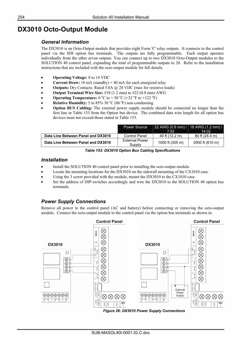
254 Solution 40 Installation Manual
SUB-MASOL40I-0001.IG.C.doc
DX3010 Octo-Output Module General Information The DX3010 is an Octo-Output module that provides eight Form 'C' relay outputs. It connects to the control panel via the SDI option bus terminals. The outputs are fully programmable. Each output operates individually from the other seven outputs. You can connect up to two DX3010 Octo-Output modules to the SOLUTION 40 control panel, expanding the total of programmable outputs to 20. Refer to the installation instructions that are included with the octo-output module for full details. • Operating Voltage: 8 to 14 VDC • Current Draw: 10 mA (standby) + 40 mA for each energized relay • Outputs: Dry Contacts: Rated 5.0A @ 28 VDC (max for resistive loads) • Output Terminal Wire Size: #18 (1.2 mm) to #22 (0.8 mm) AWG • Operating Temperature: 0 oC to + 50 oC (+32 oF to +122 oF) • Relative Humidity: 5 to 85% 30 oC (86 oF) non-condensing • Option BUS Cabling: The external power supply module should be connected no longer than the
first line in Table 153 from the Option bus device. The combined data wire length for all option bus devices must not exceed those stated in Table 153.
Power Source 22 AWG (0.8 mm) /
7.02 18 AWG (1.2 mm) /
14.02 Data Line Between Panel and DX3010 Control Panel 40 ft (12.2 m) 80 ft (24.4 m)
Data Line Between Panel and DX3010 External Power Supply 1000 ft (305 m) 2000 ft (610 m)
Table 153: DX3010 Option Bus Cabling Specifications
Installation • Install the SOLUTION 40 control panel prior to installing the octo-output module. • Locate the mounting locations for the DX3010 on the sidewall mounting of the CX1010 case. • Using the 3 screw provided with the module, mount the DX3010 to the CX1010 case. • Set the address of DIP-switches accordingly and wire the DX3010 to the SOLUTION 40 option bus
terminals. Power Supply Connections Remove all power to the control panel (AC and battery) before connecting or removing the octo-output module. Connect the octo-output module to the control panel via the option bus terminals as shown in.
Figure 26: DX3010 Power Supply Connections
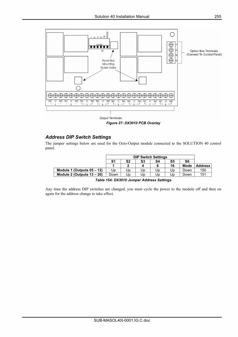
Solution 40 Installation Manual 255
SUB-MASOL40I-0001.IG.C.doc
Figure 27: DX3010 PCB Overlay
Address DIP Switch Settings The jumper settings below are used for the Octo-Output module connected to the SOLUTION 40 control panel.
DIP Switch Settings S1 S2 S3 S4 S5 S6 1 2 4 8 16 Mode Address
Module 1 (Outputs 05 – 12) Up Up Up Up Up Down 150 Module 2 (Outputs 13 – 20) Down Up Up Up Up Down 151
Table 154: DX3010 Jumper Address Settings Any time the address DIP switches are changed, you must cycle the power to the module off and then on again for the address change to take effect.
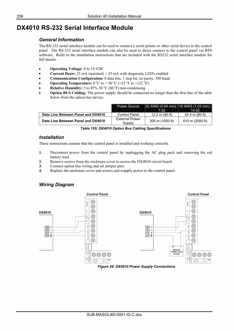
256 Solution 40 Installation Manual
SUB-MASOL40I-0001.IG.C.doc
DX4010 RS-232 Serial Interface Module
General Information The RS-232 serial interface module can be used to connect a serial printer or other serial device to the control panel. The RS-232 serial interface module can also be used to direct connect to the control panel via RPS software. Refer to the installation instructions that are included with the RS232 serial interface module for full details. • Operating Voltage: 8 to 14 VDC • Current Draw: 25 mA (nominal) + 35 mA with diagnostic LED's enabled • Communication Configuration: 8 data bits, 1 stop bit, no parity, 300 baud • Operating Temperature: 0 oC to + 50 oC (+32 oF to +122 oF) • Relative Humidity: 5 to 85% 30 oC (86 oF) non-condensing • Option BUS Cabling: The power supply should be connected no longer than the first line of the table
below from the option bus device.
Power Source 22 AWG (0.64 mm) / 7.02
18 AWG (1.02 mm) / 14.02
Data Line Between Panel and DX4010 Control Panel 12.2 m (40 ft) 24.4 m (80 ft)
Data Line Between Panel and DX4010 External Power Supply 305 m (1000 ft) 610 m (2000 ft)
Table 155: DX4010 Option Bus Cabling Specifications
Installation These instructions assume that the control panel is installed and working correctly. 1. Disconnect power from the control panel by unplugging the AC plug pack and removing the red
battery lead. 2. Remove screws from the enclosure cover to access the DX4010 circuit board. 3. Connect option bus wiring and set jumper pins. 4. Replace the enclosure cover and screws and reapply power to the control panel. Wiring Diagram
Figure 28: DX4010 Power Supply Connections
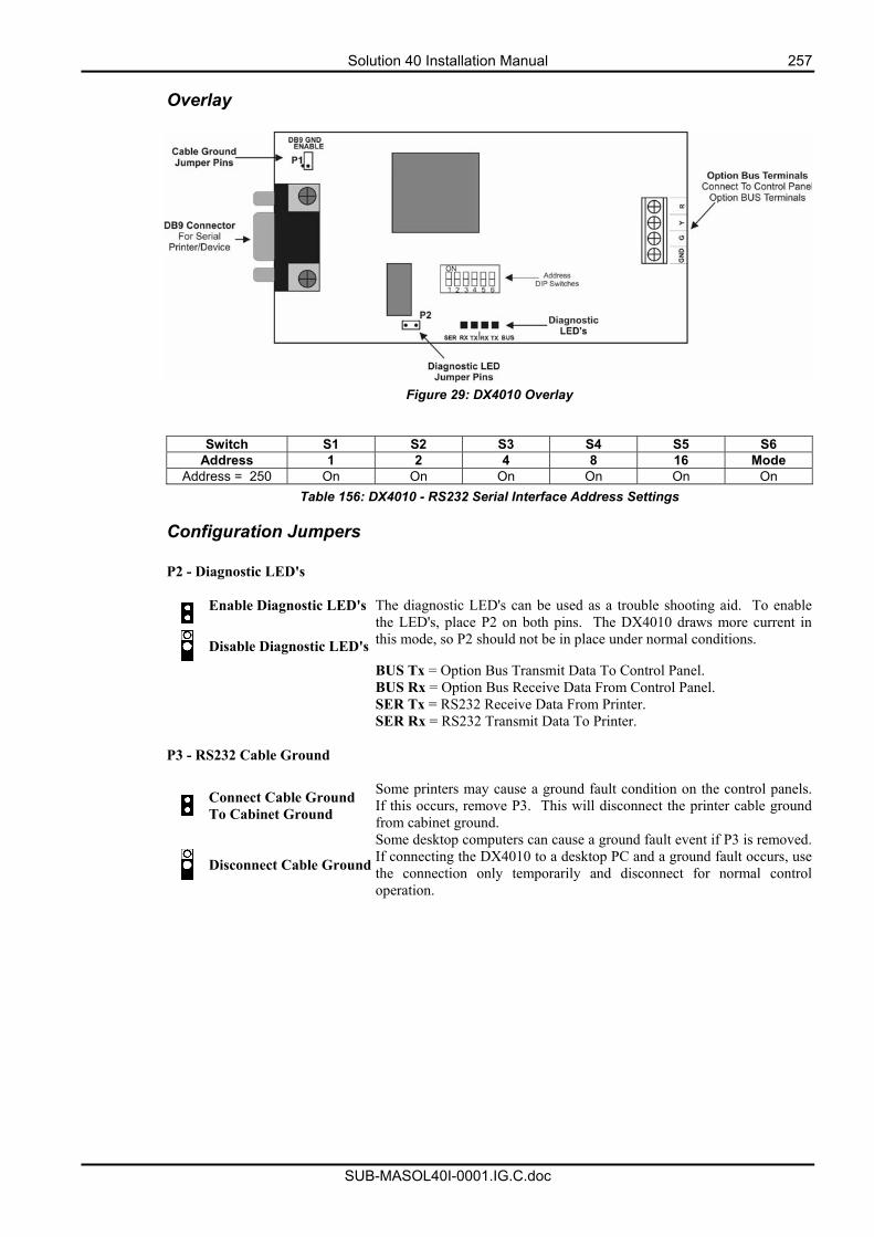
Solution 40 Installation Manual 257
SUB-MASOL40I-0001.IG.C.doc
Overlay
Figure 29: DX4010 Overlay
Switch S1 S2 S3 S4 S5 S6 Address 1 2 4 8 16 Mode
Address = 250 On On On On On On Table 156: DX4010 - RS232 Serial Interface Address Settings
Configuration Jumpers
P2 - Diagnostic LED's
Enable Diagnostic LED's
Disable Diagnostic LED's
The diagnostic LED's can be used as a trouble shooting aid. To enablethe LED's, place P2 on both pins. The DX4010 draws more current in this mode, so P2 should not be in place under normal conditions.
BUS Tx = Option Bus Transmit Data To Control Panel. BUS Rx = Option Bus Receive Data From Control Panel. SER Tx = RS232 Receive Data From Printer. SER Rx = RS232 Transmit Data To Printer.
P3 - RS232 Cable Ground
Connect Cable Ground To Cabinet Ground
Some printers may cause a ground fault condition on the control panels.If this occurs, remove P3. This will disconnect the printer cable ground from cabinet ground.
Disconnect Cable Ground
Some desktop computers can cause a ground fault event if P3 is removed.If connecting the DX4010 to a desktop PC and a ground fault occurs, usethe connection only temporarily and disconnect for normal control operation.
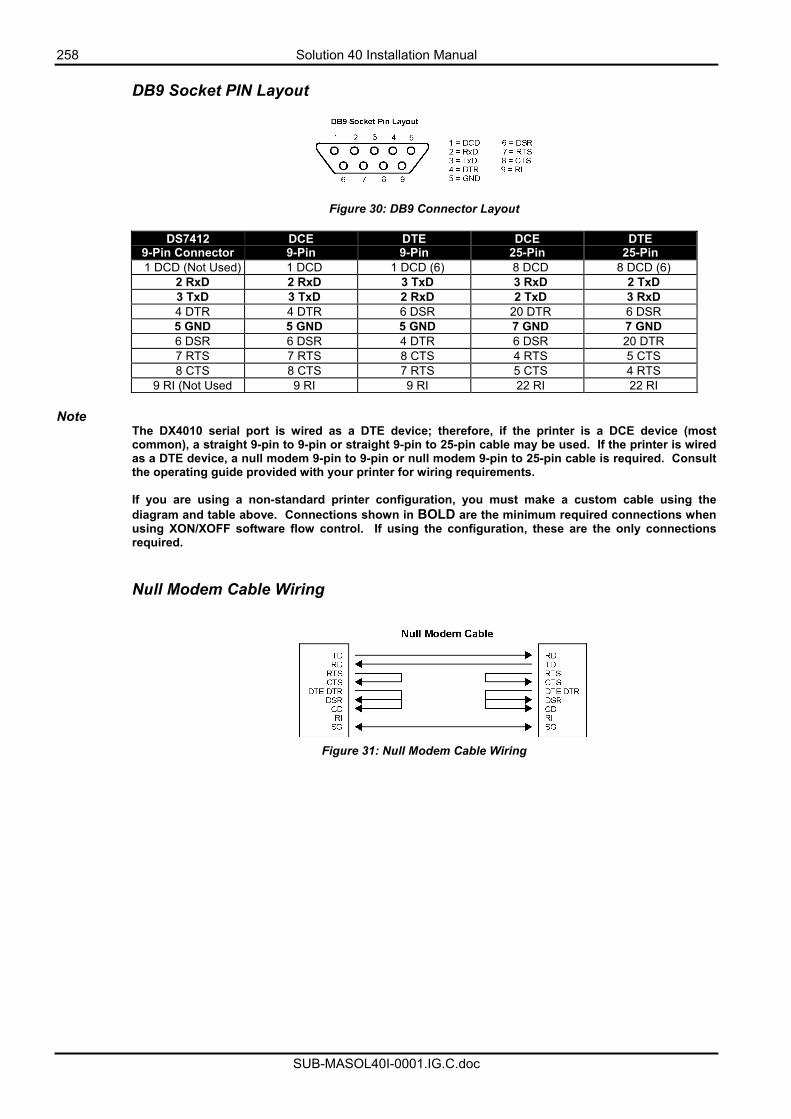
258 Solution 40 Installation Manual
SUB-MASOL40I-0001.IG.C.doc
DB9 Socket PIN Layout
Figure 30: DB9 Connector Layout
DS7412 9-Pin Connector
DCE 9-Pin
DTE 9-Pin
DCE 25-Pin
DTE 25-Pin
1 DCD (Not Used) 1 DCD 1 DCD (6) 8 DCD 8 DCD (6) 2 RxD 2 RxD 3 TxD 3 RxD 2 TxD 3 TxD 3 TxD 2 RxD 2 TxD 3 RxD 4 DTR 4 DTR 6 DSR 20 DTR 6 DSR 5 GND 5 GND 5 GND 7 GND 7 GND 6 DSR 6 DSR 4 DTR 6 DSR 20 DTR 7 RTS 7 RTS 8 CTS 4 RTS 5 CTS 8 CTS 8 CTS 7 RTS 5 CTS 4 RTS
9 RI (Not Used 9 RI 9 RI 22 RI 22 RI
Note The DX4010 serial port is wired as a DTE device; therefore, if the printer is a DCE device (most common), a straight 9-pin to 9-pin or straight 9-pin to 25-pin cable may be used. If the printer is wired as a DTE device, a null modem 9-pin to 9-pin or null modem 9-pin to 25-pin cable is required. Consult the operating guide provided with your printer for wiring requirements. If you are using a non-standard printer configuration, you must make a custom cable using the diagram and table above. Connections shown in BOLD are the minimum required connections when using XON/XOFF software flow control. If using the configuration, these are the only connections required.
Null Modem Cable Wiring
Figure 31: Null Modem Cable Wiring
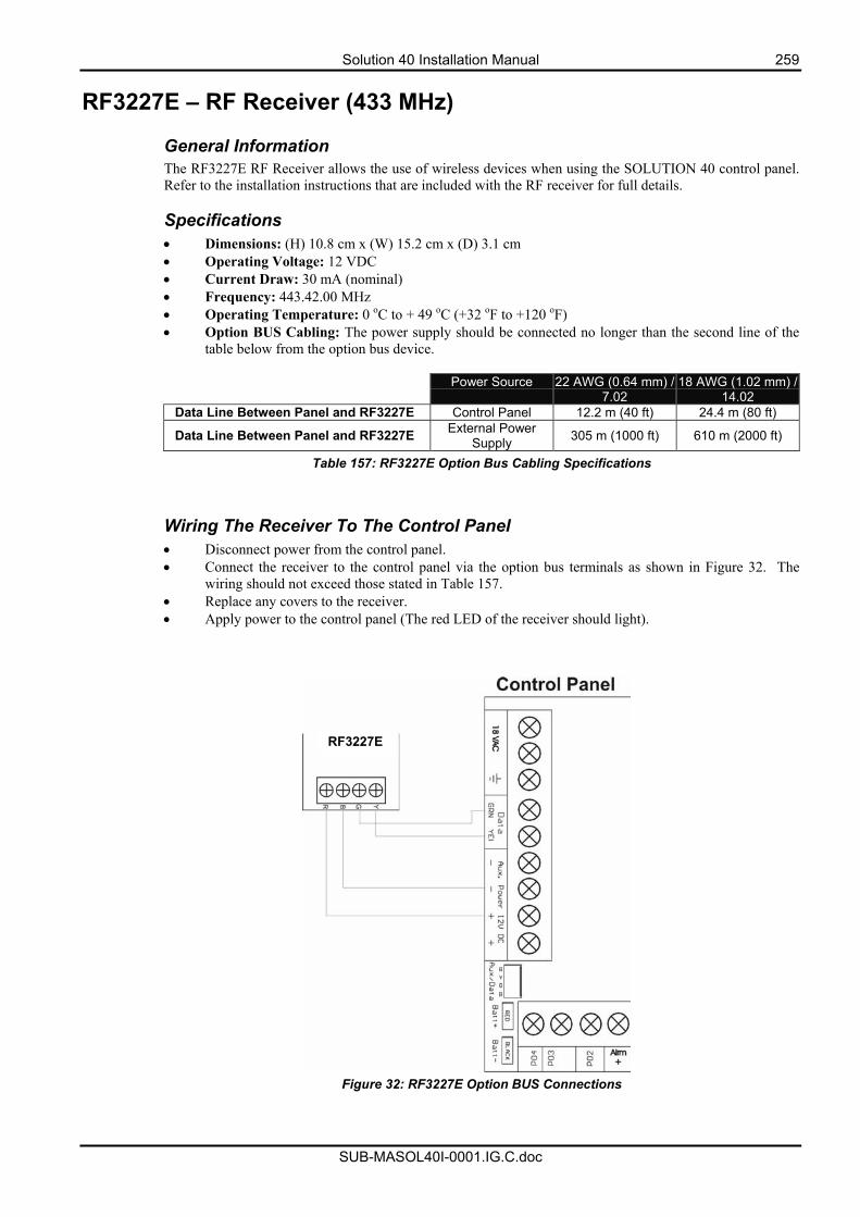
Solution 40 Installation Manual 259
SUB-MASOL40I-0001.IG.C.doc
RF3227E – RF Receiver (433 MHz)
General Information The RF3227E RF Receiver allows the use of wireless devices when using the SOLUTION 40 control panel. Refer to the installation instructions that are included with the RF receiver for full details. Specifications • Dimensions: (H) 10.8 cm x (W) 15.2 cm x (D) 3.1 cm • Operating Voltage: 12 VDC • Current Draw: 30 mA (nominal) • Frequency: 443.42.00 MHz • Operating Temperature: 0 oC to + 49 oC (+32 oF to +120 oF) • Option BUS Cabling: The power supply should be connected no longer than the second line of the
table below from the option bus device.
Power Source 22 AWG (0.64 mm) / 7.02
18 AWG (1.02 mm) / 14.02
Data Line Between Panel and RF3227E Control Panel 12.2 m (40 ft) 24.4 m (80 ft)
Data Line Between Panel and RF3227E External Power Supply 305 m (1000 ft) 610 m (2000 ft)
Table 157: RF3227E Option Bus Cabling Specifications
Wiring The Receiver To The Control Panel • Disconnect power from the control panel. • Connect the receiver to the control panel via the option bus terminals as shown in Figure 32. The
wiring should not exceed those stated in Table 157. • Replace any covers to the receiver. • Apply power to the control panel (The red LED of the receiver should light).
Figure 32: RF3227E Option BUS Connections
RF3227E
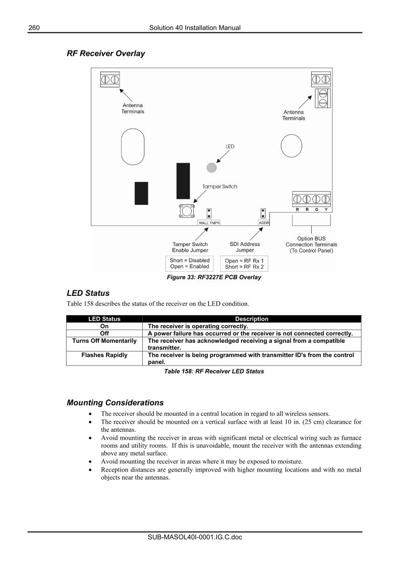
260 Solution 40 Installation Manual
SUB-MASOL40I-0001.IG.C.doc
RF Receiver Overlay
Figure 33: RF3227E PCB Overlay
LED Status Table 158 describes the status of the receiver on the LED condition.
LED Status Description On The receiver is operating correctly. Off A power failure has occurred or the receiver is not connected correctly.
Turns Off Momentarily The receiver has acknowledged receiving a signal from a compatible transmitter.
Flashes Rapidly The receiver is being programmed with transmitter ID's from the control panel.
Table 158: RF Receiver LED Status Mounting Considerations
• The receiver should be mounted in a central location in regard to all wireless sensors. • The receiver should be mounted on a vertical surface with at least 10 in. (25 cm) clearance for
the antennas. • Avoid mounting the receiver in areas with significant metal or electrical wiring such as furnace
rooms and utility rooms. If this is unavoidable, mount the receiver with the antennas extending above any metal surface.
• Avoid mounting the receiver in areas where it may be exposed to moisture. • Reception distances are generally improved with higher mounting locations and with no metal
objects near the antennas.
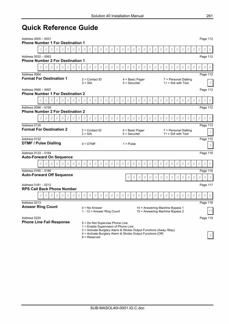
Solution 40 Installation Manual 261
SUB-MASOL40I-0001.IG.C.doc
Quick Reference Guide
Address 0000 – 0031 Page 112 Phone Number 1 For Destination 1
0 0 0 0 0 0 0 0 0 0 0 0 0 0 0 0 0 0 0 0 0 0 0 0 0 0 0 0 0 0 0 0
Address 0032 – 0063 Page 112 Phone Number 2 For Destination 1
0 0 0 0 0 0 0 0 0 0 0 0 0 0 0 0 0 0 0 0 0 0 0 0 0 0 0 0 0 0 0 0
Address 0064 Page 112 Format For Destination 1 Address 0066 – 0097 Page 113 Phone Number 1 For Destination 2
0 0 0 0 0 0 0 0 0 0 0 0 0 0 0 0 0 0 0 0 0 0 0 0 0 0 0 0 0 0 0 0
Address 0098 – 0129 Page 112 Phone Number 2 For Destination 2
0 0 0 0 0 0 0 0 0 0 0 0 0 0 0 0 0 0 0 0 0 0 0 0 0 0 0 0 0 0 0 0
Address 0130 Page 113 Format For Destination 2 Address 0132 Page 115 DTMF / Pulse Dialling
Address 0133 – 0164 Page 116 Auto-Forward On Sequence
0 0 0 0 0 0 0 0 0 0 0 0 0 0 0 0 0 0 0 0 0 0 0 0 0 0 0 0 0 0 0 0
Address 0165 – 0180 Page 116 Auto-Forward Off Sequence
Address 0181 – 0212 Page 117 RPS Call Back Phone Number
0 0 0 0 0 0 0 0 0 0 0 0 0 0 0 0 0 0 0 0 0 0 0 0 0 0 0 0 0 0 0 0
Address 0213 Page 118 Answer Ring Count
Address 0220 Page 119 Phone Line Fail Response
22 = Contact ID 4 = Basic Pager 7 = Personal Dialling 3 = SIA 5 = Securitel 11 = SIA with Text
22 = Contact ID 4 = Basic Pager 7 = Personal Dialling 3 = SIA 5 = Securitel 11 = SIA with Text
0 = DTMF 1 = Pulse 0
0 0 0 0 0 0 0 0 0 0 0 0 0 0 0 0
150 = No Answer 14 = Answering Machine Bypass 1 1 - 13 = Answer Ring Count 15 = Answering Machine Bypass 2
0 = Do Not Supervise Phone Line 1 = Enable Supervision of Phone Line 2 = Activate Burglary Alarm & Strobe Output Functions (Away /Stay) 4 = Activate Burglary Alarm & Strobe Output Functions (Off) 8 = Reserved 0
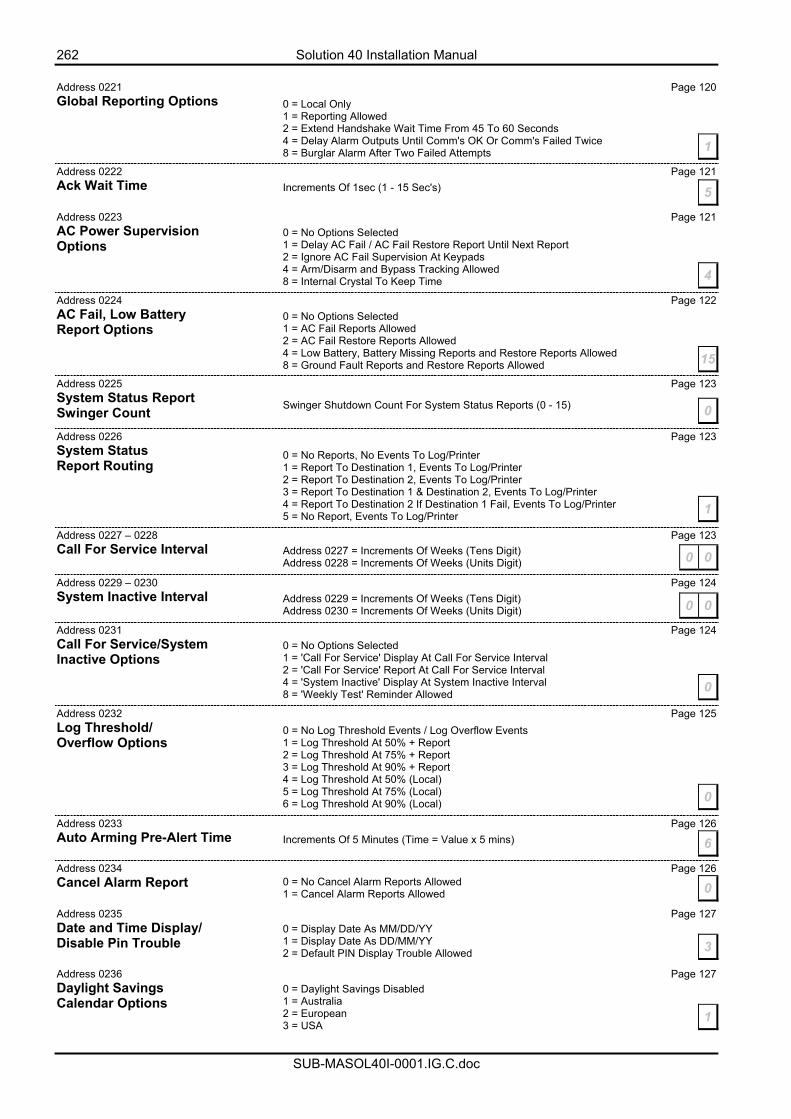
262 Solution 40 Installation Manual
SUB-MASOL40I-0001.IG.C.doc
Address 0221 Page 120 Global Reporting Options
Address 0222 Page 121 Ack Wait Time
Address 0223 Page 121 AC Power Supervision Options
Address 0224 Page 122 AC Fail, Low Battery Report Options
Address 0225 Page 123 System Status Report Swinger Count Address 0226 Page 123 System Status Report Routing
Address 0227 – 0228 Page 123 Call For Service Interval Address 0229 – 0230 Page 124 System Inactive Interval Address 0231 Page 124 Call For Service/System Inactive Options
Address 0232 Page 125 Log Threshold/ Overflow Options Address 0233 Page 126 Auto Arming Pre-Alert Time Address 0234 Page 126 Cancel Alarm Report
Address 0235 Page 127 Date and Time Display/ Disable Pin Trouble Address 0236 Page 127 Daylight Savings Calendar Options
0 = Local Only 1 = Reporting Allowed 2 = Extend Handshake Wait Time From 45 To 60 Seconds 4 = Delay Alarm Outputs Until Comm's OK Or Comm's Failed Twice 8 = Burglar Alarm After Two Failed Attempts 1
5Increments Of 1sec (1 - 15 Sec's)
0 = No Options Selected 1 = Delay AC Fail / AC Fail Restore Report Until Next Report 2 = Ignore AC Fail Supervision At Keypads 4 = Arm/Disarm and Bypass Tracking Allowed 8 = Internal Crystal To Keep Time 4
0 = No Options Selected 1 = AC Fail Reports Allowed 2 = AC Fail Restore Reports Allowed 4 = Low Battery, Battery Missing Reports and Restore Reports Allowed 8 = Ground Fault Reports and Restore Reports Allowed 15
0Swinger Shutdown Count For System Status Reports (0 - 15)
0 = No Reports, No Events To Log/Printer 1 = Report To Destination 1, Events To Log/Printer 2 = Report To Destination 2, Events To Log/Printer 3 = Report To Destination 1 & Destination 2, Events To Log/Printer 4 = Report To Destination 2 If Destination 1 Fail, Events To Log/Printer 5 = No Report, Events To Log/Printer 1
Address 0227 = Increments Of Weeks (Tens Digit) Address 0228 = Increments Of Weeks (Units Digit) 0 0
Address 0229 = Increments Of Weeks (Tens Digit) Address 0230 = Increments Of Weeks (Units Digit) 0 0
0 = No Options Selected 1 = 'Call For Service' Display At Call For Service Interval 2 = 'Call For Service' Report At Call For Service Interval 4 = 'System Inactive' Display At System Inactive Interval 8 = 'Weekly Test' Reminder Allowed 0
0 = No Log Threshold Events / Log Overflow Events 1 = Log Threshold At 50% + Report 2 = Log Threshold At 75% + Report 3 = Log Threshold At 90% + Report 4 = Log Threshold At 50% (Local) 5 = Log Threshold At 75% (Local) 6 = Log Threshold At 90% (Local) 0
Increments Of 5 Minutes (Time = Value x 5 mins) 6
00 = No Cancel Alarm Reports Allowed 1 = Cancel Alarm Reports Allowed
0 = Display Date As MM/DD/YY 1 = Display Date As DD/MM/YY 2 = Default PIN Display Trouble Allowed 3
0 = Daylight Savings Disabled 1 = Australia 2 = European 3 = USA
1
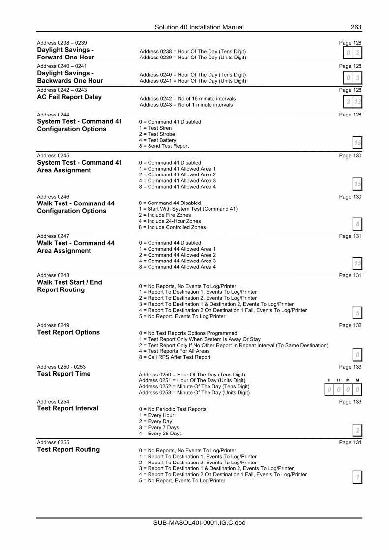
Solution 40 Installation Manual 263
SUB-MASOL40I-0001.IG.C.doc
Address 0238 – 0239 Page 128 Daylight Savings - Forward One Hour Address 0240 – 0241 Page 128 Daylight Savings - Backwards One Hour
Address 0242 – 0243 Page 128 AC Fail Report Delay
Address 0244 Page 128 System Test - Command 41 Configuration Options
Address 0245 Page 130 System Test - Command 41 Area Assignment
Address 0246 Page 130 Walk Test - Command 44 Configuration Options Address 0247 Page 131 Walk Test - Command 44 Area Assignment Address 0248 Page 131 Walk Test Start / End Report Routing
Address 0249 Page 132 Test Report Options
Address 0250 - 0253 Page 133 Test Report Time
Address 0254 Page 133 Test Report Interval
Address 0255 Page 134 Test Report Routing
0 2Address 0238 = Hour Of The Day (Tens Digit) Address 0239 = Hour Of The Day (Units Digit)
0 3Address 0240 = Hour Of The Day (Tens Digit) Address 0241 = Hour Of The Day (Units Digit)
3 12Address 0242 = No of 16 minute intervals Address 0243 = No of 1 minute intervals
0 = Command 41 Disabled 1 = Test Siren 2 = Test Strobe 4 = Test Battery 8 = Send Test Report 15
0 = Command 41 Disabled 1 = Command 41 Allowed Area 1 2 = Command 41 Allowed Area 2 4 = Command 41 Allowed Area 3 8 = Command 41 Allowed Area 4 15
0 = Command 44 Disabled 1 = Start With System Test (Command 41) 2 = Include Fire Zones 4 = Include 24-Hour Zones 8 = Include Controlled Zones 8
0 = Command 44 Disabled 1 = Command 44 Allowed Area 1 2 = Command 44 Allowed Area 2 4 = Command 44 Allowed Area 3 8 = Command 44 Allowed Area 4 15
0 = No Reports, No Events To Log/Printer 1 = Report To Destination 1, Events To Log/Printer 2 = Report To Destination 2, Events To Log/Printer 3 = Report To Destination 1 & Destination 2, Events To Log/Printer 4 = Report To Destination 2 On Destination 1 Fail, Events To Log/Printer 5 = No Report, Events To Log/Printer 5
0 = No Test Reports Options Programmed 1 = Test Report Only When System Is Away Or Stay 2 = Test Report Only If No Other Report In Repeat Interval (To Same Destination) 4 = Test Reports For All Areas 8 = Call RPS After Test Report 0
Address 0250 = Hour Of The Day (Tens Digit) Address 0251 = Hour Of The Day (Units Digit) Address 0252 = Minute Of The Day (Tens Digit) Address 0253 = Minute Of The Day (Units Digit)
H H M M
0 0 0 0
0 = No Periodic Test Reports 1 = Every Hour 2 = Every Day 3 = Every 7 Days 4 = Every 28 Days 2
0 = No Reports, No Events To Log/Printer 1 = Report To Destination 1, Events To Log/Printer 2 = Report To Destination 2, Events To Log/Printer 3 = Report To Destination 1 & Destination 2, Events To Log/Printer 4 = Report To Destination 2 On Destination 1 Fail, Events To Log/Printer 5 = No Report, Events To Log/Printer 1
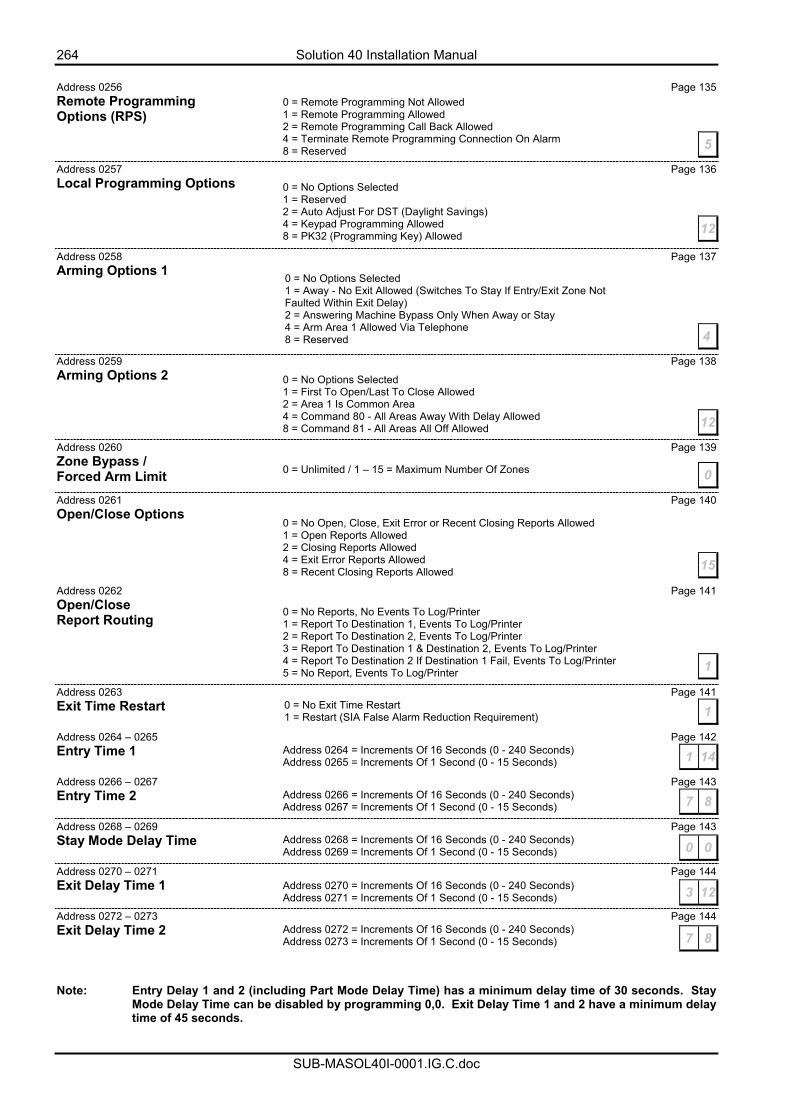
264 Solution 40 Installation Manual
SUB-MASOL40I-0001.IG.C.doc
Address 0256 Page 135 Remote Programming Options (RPS) Address 0257 Page 136 Local Programming Options
Address 0258 Page 137 Arming Options 1 Address 0259 Page 138 Arming Options 2
Address 0260 Page 139 Zone Bypass / Forced Arm Limit Address 0261 Page 140 Open/Close Options Address 0262 Page 141 Open/Close Report Routing
Address 0263 Page 141 Exit Time Restart Address 0264 – 0265 Page 142 Entry Time 1 Address 0266 – 0267 Page 143 Entry Time 2 Address 0268 – 0269 Page 143 Stay Mode Delay Time Address 0270 – 0271 Page 144 Exit Delay Time 1 Address 0272 – 0273 Page 144 Exit Delay Time 2 Note: Entry Delay 1 and 2 (including Part Mode Delay Time) has a minimum delay time of 30 seconds. Stay
Mode Delay Time can be disabled by programming 0,0. Exit Delay Time 1 and 2 have a minimum delay time of 45 seconds.
0 = Remote Programming Not Allowed 1 = Remote Programming Allowed 2 = Remote Programming Call Back Allowed 4 = Terminate Remote Programming Connection On Alarm 8 = Reserved 5
0 = No Options Selected 1 = Reserved 2 = Auto Adjust For DST (Daylight Savings) 4 = Keypad Programming Allowed 8 = PK32 (Programming Key) Allowed 12
0 = No Options Selected 1 = Away - No Exit Allowed (Switches To Stay If Entry/Exit Zone Not Faulted Within Exit Delay) 2 = Answering Machine Bypass Only When Away or Stay 4 = Arm Area 1 Allowed Via Telephone 8 = Reserved 4
0 = No Options Selected 1 = First To Open/Last To Close Allowed 2 = Area 1 Is Common Area 4 = Command 80 - All Areas Away With Delay Allowed 8 = Command 81 - All Areas All Off Allowed 12
0 = Unlimited / 1 – 15 = Maximum Number Of Zones 0
0 = No Open, Close, Exit Error or Recent Closing Reports Allowed 1 = Open Reports Allowed 2 = Closing Reports Allowed 4 = Exit Error Reports Allowed 8 = Recent Closing Reports Allowed 15
0 = No Reports, No Events To Log/Printer 1 = Report To Destination 1, Events To Log/Printer 2 = Report To Destination 2, Events To Log/Printer 3 = Report To Destination 1 & Destination 2, Events To Log/Printer 4 = Report To Destination 2 If Destination 1 Fail, Events To Log/Printer 5 = No Report, Events To Log/Printer 1
10 = No Exit Time Restart 1 = Restart (SIA False Alarm Reduction Requirement)
Address 0264 = Increments Of 16 Seconds (0 - 240 Seconds) Address 0265 = Increments Of 1 Second (0 - 15 Seconds) 1 14
Address 0266 = Increments Of 16 Seconds (0 - 240 Seconds) Address 0267 = Increments Of 1 Second (0 - 15 Seconds) 7 8
Address 0268 = Increments Of 16 Seconds (0 - 240 Seconds) Address 0269 = Increments Of 1 Second (0 - 15 Seconds) 0 0
Address 0270 = Increments Of 16 Seconds (0 - 240 Seconds) Address 0271 = Increments Of 1 Second (0 - 15 Seconds) 3 12
Address 0272 = Increments Of 16 Seconds (0 - 240 Seconds) Address 0273 = Increments Of 1 Second (0 - 15 Seconds) 7 8
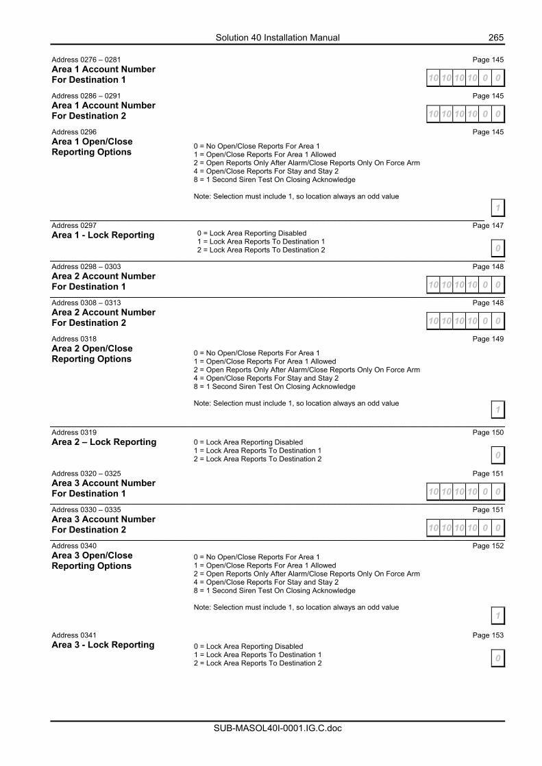
Solution 40 Installation Manual 265
SUB-MASOL40I-0001.IG.C.doc
Address 0276 – 0281 Page 145 Area 1 Account Number For Destination 1
Address 0286 – 0291 Page 145 Area 1 Account Number For Destination 2
Address 0296 Page 145 Area 1 Open/Close Reporting Options Address 0297 Page 147 Area 1 - Lock Reporting Address 0298 – 0303 Page 148 Area 2 Account Number For Destination 1 Address 0308 – 0313 Page 148 Area 2 Account Number For Destination 2
Address 0318 Page 149 Area 2 Open/Close Reporting Options Address 0319 Page 150 Area 2 – Lock Reporting Address 0320 – 0325 Page 151 Area 3 Account Number For Destination 1
Address 0330 – 0335 Page 151 Area 3 Account Number For Destination 2
Address 0340 Page 152 Area 3 Open/Close Reporting Options
Address 0341 Page 153 Area 3 - Lock Reporting
10 10 10 10 0 0
10 10 10 10 0 0
0 = No Open/Close Reports For Area 1 1 = Open/Close Reports For Area 1 Allowed 2 = Open Reports Only After Alarm/Close Reports Only On Force Arm 4 = Open/Close Reports For Stay and Stay 2 8 = 1 Second Siren Test On Closing Acknowledge Note: Selection must include 1, so location always an odd value
1
0 = Lock Area Reporting Disabled 1 = Lock Area Reports To Destination 1 2 = Lock Area Reports To Destination 2 0
10 10 10 10 0 0
10 10 10 10 0 0
0 = No Open/Close Reports For Area 1 1 = Open/Close Reports For Area 1 Allowed 2 = Open Reports Only After Alarm/Close Reports Only On Force Arm 4 = Open/Close Reports For Stay and Stay 2 8 = 1 Second Siren Test On Closing Acknowledge Note: Selection must include 1, so location always an odd value
1
0 = Lock Area Reporting Disabled 1 = Lock Area Reports To Destination 1 2 = Lock Area Reports To Destination 2 0
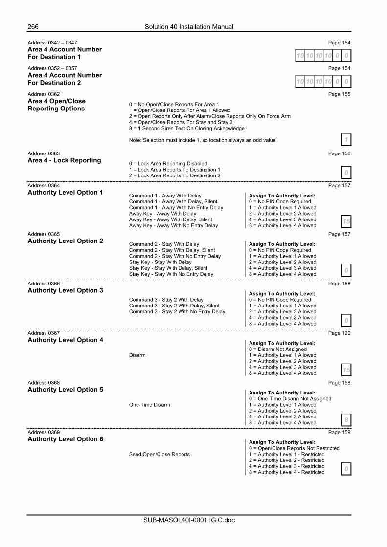
266 Solution 40 Installation Manual
SUB-MASOL40I-0001.IG.C.doc
Address 0342 – 0347 Page 154 Area 4 Account Number For Destination 1
Address 0352 – 0357 Page 154 Area 4 Account Number For Destination 2
Address 0362 Page 155 Area 4 Open/Close Reporting Options Address 0363 Page 156 Area 4 - Lock Reporting Address 0364 Page 157 Authority Level Option 1
Address 0365 Page 157 Authority Level Option 2
Address 0366 Page 158 Authority Level Option 3
Address 0367 Page 120 Authority Level Option 4
Address 0368 Page 158 Authority Level Option 5
Address 0369 Page 159 Authority Level Option 6
10 10 10 10 0 0
10 10 10 10 0 0
0 = No Open/Close Reports For Area 1 1 = Open/Close Reports For Area 1 Allowed 2 = Open Reports Only After Alarm/Close Reports Only On Force Arm 4 = Open/Close Reports For Stay and Stay 2 8 = 1 Second Siren Test On Closing Acknowledge Note: Selection must include 1, so location always an odd value 1
0 = Lock Area Reporting Disabled 1 = Lock Area Reports To Destination 1 2 = Lock Area Reports To Destination 2 0
Command 1 - Away With Delay Assign To Authority Level: Command 1 - Away With Delay, Silent 0 = No PIN Code Required Command 1 - Away With No Entry Delay 1 = Authority Level 1 Allowed Away Key - Away With Delay 2 = Authority Level 2 Allowed Away Key - Away With Delay, Silent 4 = Authority Level 3 Allowed Away Key - Away With No Entry Delay 8 = Authority Level 4 Allowed
15
Command 2 - Stay With Delay Assign To Authority Level: Command 2 - Stay With Delay, Silent 0 = No PIN Code Required Command 2 - Stay With No Entry Delay 1 = Authority Level 1 Allowed Stay Key - Stay With Delay 2 = Authority Level 2 Allowed Stay Key - Stay With Delay, Silent 4 = Authority Level 3 Allowed Stay Key - Stay With No Entry Delay 8 = Authority Level 4 Allowed 0
Assign To Authority Level: Command 3 - Stay 2 With Delay 0 = No PIN Code Required Command 3 - Stay 2 With Delay, Silent 1 = Authority Level 1 Allowed Command 3 - Stay 2 With No Entry Delay 2 = Authority Level 2 Allowed 4 = Authority Level 3 Allowed 8 = Authority Level 4 Allowed 0
Assign To Authority Level: 0 = Disarm Not Assigned Disarm 1 = Authority Level 1 Allowed 2 = Authority Level 2 Allowed 4 = Authority Level 3 Allowed 8 = Authority Level 4 Allowed 15
Assign To Authority Level: 0 = One-Time Disarm Not Assigned One-Time Disarm 1 = Authority Level 1 Allowed 2 = Authority Level 2 Allowed 4 = Authority Level 3 Allowed 8 = Authority Level 4 Allowed 8
Assign To Authority Level: 0 = Open/Close Reports Not Restricted Send Open/Close Reports 1 = Authority Level 1 - Restricted 2 = Authority Level 2 - Restricted 4 = Authority Level 3 - Restricted 8 = Authority Level 4 - Restricted 0
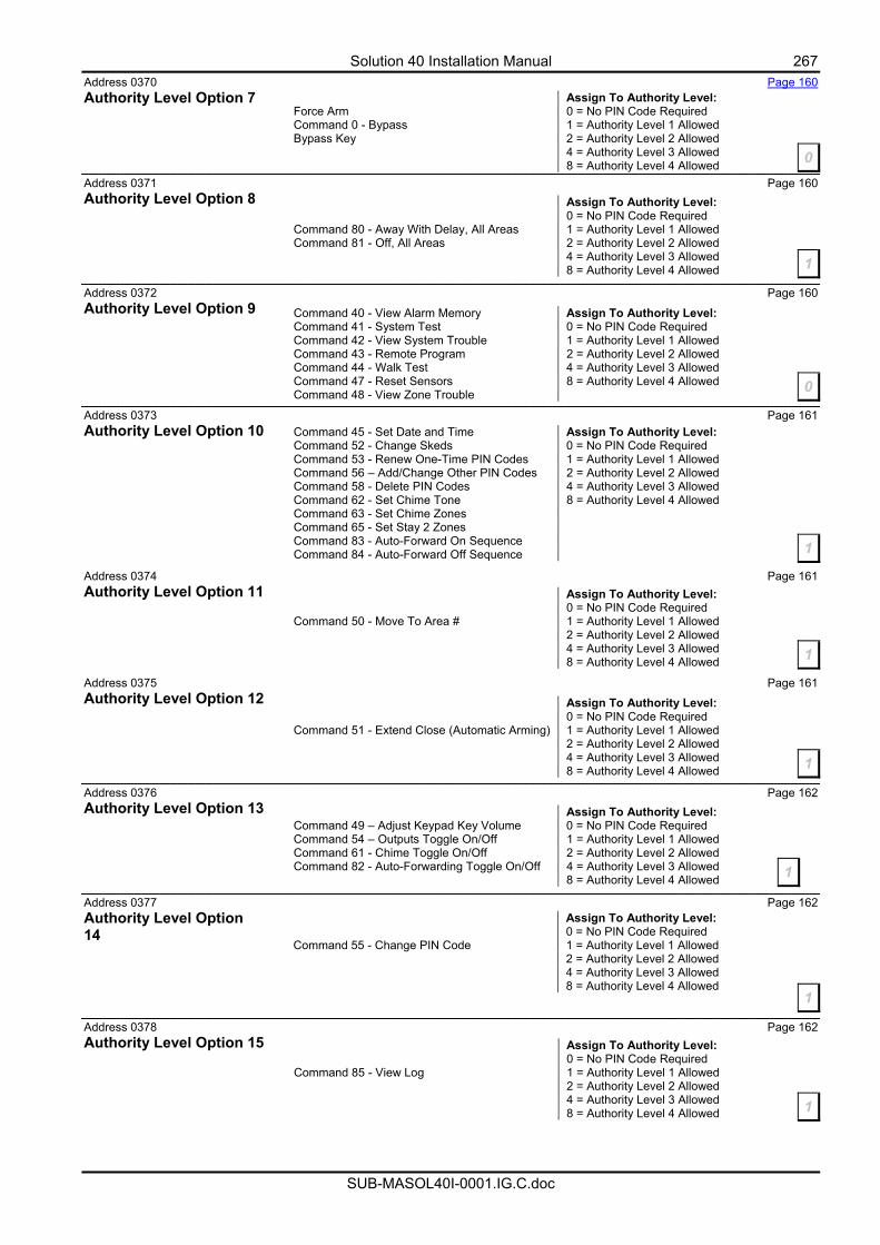
Solution 40 Installation Manual 267
SUB-MASOL40I-0001.IG.C.doc
Address 0370 Page 160 Authority Level Option 7 Address 0371 Page 160 Authority Level Option 8
Address 0372 Page 160 Authority Level Option 9 Address 0373 Page 161 Authority Level Option 10
Address 0374 Page 161 Authority Level Option 11 Address 0375 Page 161 Authority Level Option 12
Address 0376 Page 162 Authority Level Option 13
Address 0377 Page 162 Authority Level Option 14
Address 0378 Page 162 Authority Level Option 15
Assign To Authority Level: Force Arm 0 = No PIN Code Required Command 0 - Bypass 1 = Authority Level 1 Allowed Bypass Key 2 = Authority Level 2 Allowed 4 = Authority Level 3 Allowed 8 = Authority Level 4 Allowed 0
Assign To Authority Level: 0 = No PIN Code Required Command 80 - Away With Delay, All Areas 1 = Authority Level 1 Allowed Command 81 - Off, All Areas 2 = Authority Level 2 Allowed 4 = Authority Level 3 Allowed 8 = Authority Level 4 Allowed 1
Command 40 - View Alarm Memory Assign To Authority Level: Command 41 - System Test 0 = No PIN Code Required Command 42 - View System Trouble 1 = Authority Level 1 Allowed Command 43 - Remote Program 2 = Authority Level 2 Allowed Command 44 - Walk Test 4 = Authority Level 3 Allowed Command 47 - Reset Sensors 8 = Authority Level 4 Allowed Command 48 - View Zone Trouble 0
Command 45 - Set Date and Time Assign To Authority Level: Command 52 - Change Skeds 0 = No PIN Code Required Command 53 - Renew One-Time PIN Codes 1 = Authority Level 1 Allowed Command 56 – Add/Change Other PIN Codes 2 = Authority Level 2 Allowed Command 58 - Delete PIN Codes 4 = Authority Level 3 Allowed Command 62 - Set Chime Tone 8 = Authority Level 4 Allowed Command 63 - Set Chime Zones Command 65 - Set Stay 2 Zones Command 83 - Auto-Forward On Sequence Command 84 - Auto-Forward Off Sequence 1
Assign To Authority Level: 0 = No PIN Code Required Command 50 - Move To Area # 1 = Authority Level 1 Allowed 2 = Authority Level 2 Allowed 4 = Authority Level 3 Allowed 8 = Authority Level 4 Allowed 1
Assign To Authority Level: 0 = No PIN Code Required Command 51 - Extend Close (Automatic Arming) 1 = Authority Level 1 Allowed 2 = Authority Level 2 Allowed 4 = Authority Level 3 Allowed 8 = Authority Level 4 Allowed 1
Assign To Authority Level: Command 49 – Adjust Keypad Key Volume 0 = No PIN Code Required Command 54 – Outputs Toggle On/Off 1 = Authority Level 1 Allowed Command 61 - Chime Toggle On/Off 2 = Authority Level 2 Allowed Command 82 - Auto-Forwarding Toggle On/Off 4 = Authority Level 3 Allowed 8 = Authority Level 4 Allowed 1
Assign To Authority Level: 0 = No PIN Code Required Command 55 - Change PIN Code 1 = Authority Level 1 Allowed 2 = Authority Level 2 Allowed 4 = Authority Level 3 Allowed 8 = Authority Level 4 Allowed
1
Assign To Authority Level: 0 = No PIN Code Required Command 85 - View Log 1 = Authority Level 1 Allowed 2 = Authority Level 2 Allowed 4 = Authority Level 3 Allowed 8 = Authority Level 4 Allowed 1
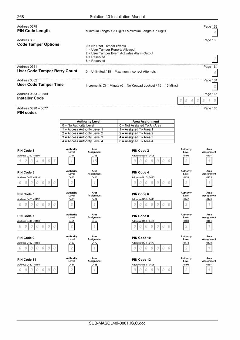
268 Solution 40 Installation Manual
SUB-MASOL40I-0001.IG.C.doc
Address 0379 Page 163 PIN Code Length Address 380 Page 163 Code Tamper Options
Address 0381 Page 164 User Code Tamper Retry Count Address 0382 Page 164 User Code Tamper Time Address 0383 – 0389 Page 165 Installer Code Address 0390 – 0677 Page 165 PIN codes
Authority Level Area Assignment 0 = No Authority Level 0 = Not Assigned To An Area 1 = Access Authority Level 1 1 = Assigned To Area 1 2 = Access Authority Level 2 2 = Assigned To Area 2 3 = Access Authority Level 3 4 = Assigned To Area 3 4 = Access Authority Level 4 8 = Assigned To Area 4
PIN Code 1 Authority
Level Area
Assignment PIN Code 2 Authority Level
Area Assignment
Address 0390 - 0396 0397 0398 Address 0399 - 0405 0406 0407
1 2 3 4 5 6 7 1 15 0 0 0 0 0 0 0 2 1
PIN Code 3 Authority
Level Area Assignment PIN Code 4 Authority
Level Area Assignment
Address 0408 - 0414 0415 0416 Address 0417 - 0423 0424 0425
0 0 0 0 0 0 0 2 1 0 0 0 0 0 0 0 2 1
PIN Code 5 Authority
Level Area Assignment PIN Code 6 Authority
Level Area Assignment
Address 0426 - 0432 0433 0434 Address 0435 - 0441 0442 0443
0 0 0 0 0 0 0 2 1 0 0 0 0 0 0 0 2 1
PIN Code 7 Authority
Level Area Assignment PIN Code 8 Authority
Level Area Assignment
Address 0444 - 0450 0451 0452 Address 0453 - 0459 0460 0461
0 0 0 0 0 0 0 2 1 0 0 0 0 0 0 0 2 1
PIN Code 9 Authority
Level Area Assignment PIN Code 10 Authority
Level Area Assignment
Address 0462 - 0468 0469 0470 Address 0471 - 0477 0478 0479
0 0 0 0 0 0 0 2 1 0 0 0 0 0 0 0 2 1
PIN Code 11 Authority
Level Area Assignment PIN Code 12 Authority
Level Area Assignment
Address 0480 - 0486 0487 0488 Address 0489 - 0495 0496 0497
0 0 0 0 0 0 0 2 1 0 0 0 0 0 0 0 2 1
Minimum Length = 3 Digits / Maximum Length = 7 Digits 4
0 = No User Tamper Events 1 = User Tamper Reports Allowed 2 = User Tamper Event Activates Alarm Output 4 = Reserved 8 = Reserved 1
0 = Unlimited / 15 = Maximum Incorrect Attempts 4
Increments Of 1 Minute (0 = No Keypad Lockout / 15 = 15 Min's) 2
6 5 4 3 2 1 0
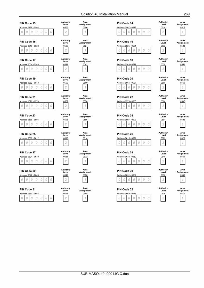
Solution 40 Installation Manual 269
SUB-MASOL40I-0001.IG.C.doc
PIN Code 13 Authority
Level Area Assignment PIN Code 14 Authority
Level Area Assignment
Address 0498 - 0504 0505 0506 Address 0507 - 0513 0514 0515
0 0 0 0 0 0 0 2 1 0 0 0 0 0 0 0 2 1
PIN Code 15 Authority
Level Area Assignment PIN Code 16 Authority
Level Area Assignment
Address 0516 - 0522 0523 0524 Address 0525 - 0531 0532 0533
0 0 0 0 0 0 0 2 1 0 0 0 0 0 0 0 2 1
PIN Code 17 Authority
Level Area Assignment PIN Code 18 Authority
Level Area Assignment
Address 0534 - 0540 0541 0542 Address 0543 - 0549 0550 0551
0 0 0 0 0 0 0 2 1 0 0 0 0 0 0 0 2 1
PIN Code 19 Authority
Level Area Assignment PIN Code 20 Authority
Level Area Assignment
Address 0552 - 0558 0559 0560 Address 0561 - 0567 0568 0569
0 0 0 0 0 0 0 2 1 0 0 0 0 0 0 0 2 1
PIN Code 21 Authority
Level Area Assignment PIN Code 22 Authority
Level Area Assignment
Address 0570 - 0576 0577 0578 Address 0579 - 0585 0586 0587
0 0 0 0 0 0 0 2 1 0 0 0 0 0 0 0 2 1
PIN Code 23 Authority
Level Area Assignment PIN Code 24 Authority
Level Area Assignment
Address 0588 - 0594 0595 0596 Address 0597 - 0603 0604 0605
0 0 0 0 0 0 0 2 1 0 0 0 0 0 0 0 2 1
PIN Code 25 Authority
Level Area Assignment PIN Code 26 Authority
Level Area Assignment
Address 0606 - 0612 0613 0614 Address 0615 - 0621 0622 0623
0 0 0 0 0 0 0 2 1 0 0 0 0 0 0 0 2 1
PIN Code 27 Authority
Level Area Assignment PIN Code 28 Authority
Level Area Assignment
Address 0624 - 0630 0631 0632 Address 0633 - 0639 0640 0641
0 0 0 0 0 0 0 2 1 0 0 0 0 0 0 0 2 1
PIN Code 29 Authority
Level Area Assignment PIN Code 30 Authority
Level Area Assignment
Address 0642 - 0648 0649 0650 Address 0651 - 0657 0658 0659
0 0 0 0 0 0 0 2 1 0 0 0 0 0 0 0 2 1
PIN Code 31 Authority
Level Area Assignment PIN Code 32 Authority
Level Area Assignment
Address 0660 - 0666 0667 0668 Address 0669 - 0675 0676 0677
0 0 0 0 0 0 0 2 1 0 0 0 0 0 0 0 2 1
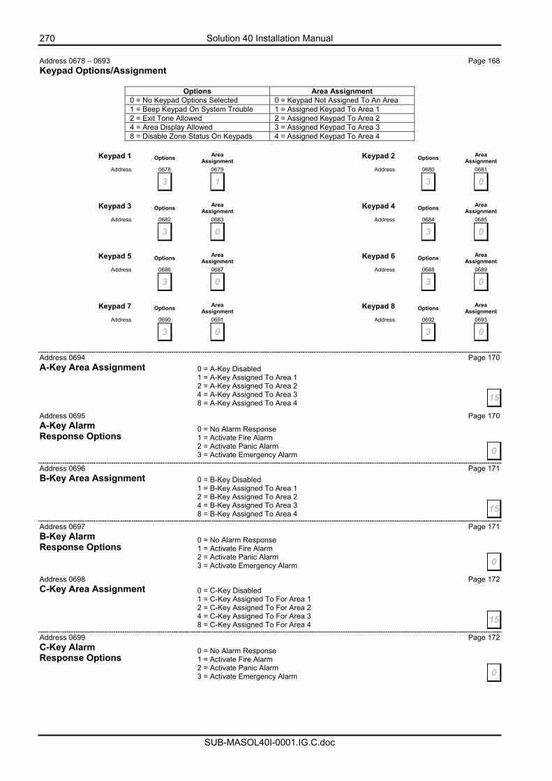
270 Solution 40 Installation Manual
SUB-MASOL40I-0001.IG.C.doc
Address 0678 – 0693 Page 168 Keypad Options/Assignment
Options Area Assignment 0 = No Keypad Options Selected 0 = Keypad Not Assigned To An Area 1 = Beep Keypad On System Trouble 1 = Assigned Keypad To Area 1 2 = Exit Tone Allowed 2 = Assigned Keypad To Area 2 4 = Area Display Allowed 3 = Assigned Keypad To Area 3 8 = Disable Zone Status On Keypads 4 = Assigned Keypad To Area 4
Keypad 1 Options Area
Assignment Keypad 2 Options Area Assignment
Address 0678 0679 Address 0680 0681
3 1 3 0
Keypad 3 Options Area
Assignment Keypad 4 Options Area Assignment
Address 0682 0683 Address 0684 0685
3 0 3 0
Keypad 5 Options Area
Assignment Keypad 6 Options Area Assignment
Address 0686 0687 Address 0688 0689
3 0 3 0
Keypad 7 Options Area
Assignment Keypad 8 Options Area Assignment
Address 0690 0691 Address 0692 0693
3 0 3 0
Address 0694 Page 170 A-Key Area Assignment
Address 0695 Page 170 A-Key Alarm Response Options Address 0696 Page 171 B-Key Area Assignment
Address 0697 Page 171 B-Key Alarm Response Options Address 0698 Page 172 C-Key Area Assignment
Address 0699 Page 172 C-Key Alarm Response Options
0 = A-Key Disabled 1 = A-Key Assigned To Area 1 2 = A-Key Assigned To Area 2 4 = A-Key Assigned To Area 3 8 = A-Key Assigned To Area 4 15
0 = No Alarm Response 1 = Activate Fire Alarm 2 = Activate Panic Alarm 3 = Activate Emergency Alarm 0
0 = B-Key Disabled 1 = B-Key Assigned To Area 1 2 = B-Key Assigned To Area 2 4 = B-Key Assigned To Area 3 8 = B-Key Assigned To Area 4 15
0 = No Alarm Response 1 = Activate Fire Alarm 2 = Activate Panic Alarm 3 = Activate Emergency Alarm 0
0 = C-Key Disabled 1 = C-Key Assigned To For Area 1 2 = C-Key Assigned To For Area 2 4 = C-Key Assigned To For Area 3 8 = C-Key Assigned To For Area 4 15
0 = No Alarm Response 1 = Activate Fire Alarm 2 = Activate Panic Alarm 3 = Activate Emergency Alarm 0
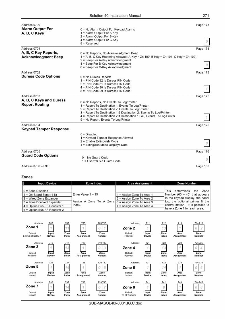
Solution 40 Installation Manual 271
SUB-MASOL40I-0001.IG.C.doc
Address 0700 Page 173 Alarm Output For A, B, C Keys
Address 0701 Page 173 A, B, C Key Reports, Acknowledgment Beep
Address 0702 Page 173 Duress Code Options
Address 0703 Page 175 A, B, C Keys and Duress Report Routing
Address 0704 Page 175 Keypad Tamper Response
Address 0705 Page 176 Guard Code Options
Address 0706 – 0905 Page 180
Zones Input Device Zone Index Area Assignment Zone Number
0 = Zone Disabled 1 = On-Board Zone (1-8) 1 = Assign Zone To Area 1 2 = Wired Zone Expander 2 = Assign Zone To Area 2 3 = Zone Doubled Expander 3 = Assign Zone To Area 3 4 = Option Bus RF Receiver 1 4 = Assign Zone To Area 4 5 = Option Bus RF Receiver 2
Enter Value 1 – 15 Assign A Zone To A Zone Index.
This determines the Zone Number (00 – 40) that appears In the keypad display, the panel log, the optional printer & the central station. It is possible to have a Zone 1 for each area.
Address 706 707 708 709/710 Address 711 712 713 714/715
Zone 1 1 11 1 0 1 Zone 2 1 13 1 0 2 Default
Entry/Exit Delay-1 Input
Device Zone Index
Area Assignment
Zone Number
Default Follower
Input Device
Zone Index
Area Assignment
Zone Number
Address 716 717 718 719/720 Address 721 722 723 724/725
Zone 3 1 13 1 0 3 Zone 4 1 13 1 0 4 Default
Follower Input
Device Zone Index
Area Assignment
Zone Number
Default Follower
Input Device
Zone Index
Area Assignment
Zone Number
Address 726 727 728 729/730 Address 731 732 733 734/735
Zone 5 1 14 1 0 5 Zone 6 1 14 1 0 6 Default Instant
Input Device
Zone Index
Area Assignment
Zone Number
Default Instant
Input Device
Zone Index
Area Assignment
Zone Number
Address 736 737 738 739/740 Address 741 742 743 744/745
Zone 7 1 14 1 0 7 Zone 8 1 8 1 0 8 Default Instant
Input Device
Zone Index
Area Assignment
Zone Number
Default 24-Hr Tamper
Input Device
Zone Index
Area Assignment
Zone Number
0 = No Alarm Output For Keypad Alarms 1 = Alarm Output For A-Key 2 = Alarm Output For B-Key 4 = Alarm Output For C-Key 8 = Reserved 0
0 = No Reports, No Acknowledgment Beep 1 = A, B, C Key Reporting Allowed (A-Key = Zn 100, B-Key = Zn 101, C-Key = Zn 102) 2 = Beep For A-Key Acknowledgment 4 = Beep For B-Key Acknowledgment 8 = Beep For C-Key Acknowledgment 0
0 = No Duress Reports 1 = PIN Code 32 Is Duress PIN Code 2 = PIN Code 31 Is Duress PIN Code 4 = PIN Code 30 Is Duress PIN Code 8 = PIN Code 29 Is Duress PIN Code 1
0 = No Reports, No Events To Log/Printer 1 = Report To Destination 1, Events To Log/Printer 2 = Report To Destination 2, Events To Log/Printer 3 = Report To Destination 1 & Destination 2, Events To Log/Printer 4 = Report To Destination 2 If Destination 1 Fail, Events To Log/Printer 5 = No Report, Events To Log/Printer
1
0 = Disabled 1 = Keypad Tamper Response Allowed 2 = Enable Extinguish Mode 4 = Extinguish Mode Displays Date 0
00 = No Guard Code 1 = User 28 is a Guard Code
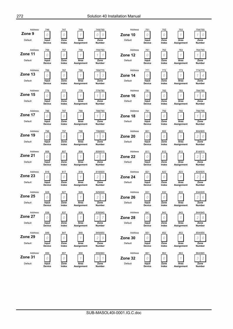
272 Solution 40 Installation Manual
SUB-MASOL40I-0001.IG.C.doc
Address 746 747 748 749/750 Address 751 752 753 754/755
Zone 9 0 0 1 0 9 Zone 10 0 0 1 1 0 Default
Input
Device Zone Index
Area Assignment
Zone Number
Default
Input Device
Zone Index
Area Assignment
Zone Number
Address 756 757 758 759/760 Address 761 762 763 764/765
Zone 11 0 0 1 1 1 Zone 12 0 0 1 1 2 Default
Input
Device Zone Index
Area Assignment
Zone Number
Default
Input Device
Zone Index
Area Assignment
Zone Number
Address 766 767 768 769/770 Address 771 772 773 774/775
Zone 13 0 0 1 1 3 Zone 14 0 0 1 1 4 Default
Input
Device Zone Index
Area Assignment
Zone Number
Default
Input Device
Zone Index
Area Assignment
Zone Number
Address 776 777 778 779/780 Address 781 782 783 784/785
Zone 15 0 0 1 1 5 Zone 16 0 0 1 1 6 Default
Input
Device Zone Index
Area Assignment
Zone Number
Default
Input Device
Zone Index
Area Assignment
Zone Number
Address 786 787 788 789/790 Address 791 792 793 794/795
Zone 17 0 0 1 1 7 Zone 18 0 0 1 1 8 Default
Input
Device Zone Index
Area Assignment
Zone Number
Default
Input Device
Zone Index
Area Assignment
Zone Number
Address 796 797 798 799/800 Address 801 802 803 804/805
Zone 19 0 0 1 1 9 Zone 20 0 0 1 2 0 Default
Input
Device Zone Index
Area Assignment
Zone Number
Default
Input Device
Zone Index
Area Assignment
Zone Number
Address 806 807 808 809/810 Address 811 812 813 814/815
Zone 21 0 0 1 2 1 Zone 22 0 0 1 2 2 Default
Input
Device Zone Index
Area Assignment
Zone Number
Default
Input Device
Zone Index
Area Assignment
Zone Number
Address 816 817 818 819/820 Address 821 822 823 824/825
Zone 23 0 0 1 2 3 Zone 24 0 0 1 2 4 Default
Input
Device Zone Index
Area Assignment
Zone Number
Default
Input Device
Zone Index
Area Assignment
Zone Number
Address 826 827 828 829/830 Address 831 832 833 834/835
Zone 25 0 0 1 2 5 Zone 26 0 0 1 2 6 Default
Input
Device Zone Index
Area Assignment
Zone Number
Default
Input Device
Zone Index
Area Assignment
Zone Number
Address 836 837 838 839/840 Address 841 842 843 844/845
Zone 27 0 0 1 2 7 Zone 28 0 0 1 2 8 Default
Input
Device Zone Index
Area Assignment
Zone Number
Default
Input Device
Zone Index
Area Assignment
Zone Number
Address 846 847 848 849/850 Address 851 852 853 854/855
Zone 29 0 0 1 2 9 Zone 30 0 0 1 3 0 Default
Input
Device Zone Index
Area Assignment
Zone Number
Default
Input Device
Zone Index
Area Assignment
Zone Number
Address 856 857 858 859/860 Address 861 862 863 864/865
Zone 31 0 0 1 3 1 Zone 32 0 0 1 3 2 Default
Input
Device Zone Index
Area Assignment
Zone Number
Default
Input Device
Zone Index
Area Assignment
Zone Number
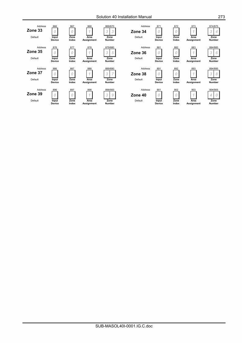
Solution 40 Installation Manual 273
SUB-MASOL40I-0001.IG.C.doc
Address 866 867 868 869/870 Address 871 872 873 874/875
Zone 33 0 0 1 3 3 Zone 34 0 0 1 3 4 Default
Input
Device Zone Index
Area Assignment
Zone Number
Default
Input Device
Zone Index
Area Assignment
Zone Number
Address 876 877 878 879/880 Address 881 882 883 884/885
Zone 35 0 0 1 3 5 Zone 36 0 0 1 3 6 Default
Input
Device Zone Index
Area Assignment
Zone Number
Default
Input Device
Zone Index
Area Assignment
Zone Number
Address 886 887 888 889/890 Address 891 892 893 894/895
Zone 37 0 0 1 3 7 Zone 38 0 0 1 3 8 Default
Input
Device Zone Index
Area Assignment
Zone Number
Default
Input Device
Zone Index
Area Assignment
Zone Number
Address 896 897 898 899/900 Address 901 902 903 904/905
Zone 39 0 0 1 3 9 Zone 40 0 0 1 4 0 Default
Input
Device Zone Index
Area Assignment
Zone Number
Default
Input Device
Zone Index
Area Assignment
Zone Number
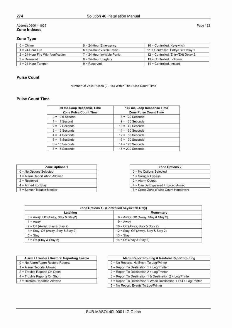
274 Solution 40 Installation Manual
SUB-MASOL40I-0001.IG.C.doc
Address 0906 – 1025 Page 182 Zone Indexes Zone Type
0 = Chime 5 = 24-Hour Emergency 10 = Controlled, Keyswitch 1 = 24-Hour Fire 6 = 24-Hour Visible Panic 11 = Controlled, Entry/Exit Delay 1 2 = 24-Hour Fire With Verification 7 = 24-Hour Invisible Panic 12 = Controlled, Entry/Exit Delay 2 3 = Reserved 8 = 24-Hour Burglary 13 = Controlled, Follower 4 = 24-Hour Tamper 9 = Reserved 14 = Controlled, Instant
Pulse Count
Number Of Valid Pulses (0 - 15) Within The Pulse Count Time Pulse Count Time
50 ms Loop Response Time Zone Pulse Count Time
160 ms Loop Response Time Zone Pulse Count Time
0 = 0.5 Second 8 = 20 Seconds 1 = 1 Second 9 = 30 Seconds 2 = 2 Seconds 10 = 40 Seconds 3 = 3 Seconds 11 = 50 Seconds 4 = 4 Seconds 12 = 60 Seconds 5 = 5 Seconds 13 = 90 Seconds 6 = 10 Seconds 14 = 120 Seconds 7 = 15 Seconds 15 = 200 Seconds
Zone Options 1 Zone Options 2 0 = No Options Selected 0 = No Options Selected 1 = Alarm Report Abort Allowed 1 = Swinger Bypass 2 = Reserved 2 = Alarm Output 4 = Armed For Stay 4 = Can Be Bypassed / Forced Armed 8 = Sensor Trouble Monitor 8 = Cross-Zone (Pulse Count Handover)
Zone Options 1 - (Controlled Keyswitch Only) Latching Momentary
0 = Away, Off (Away, Stay & Stay2) 8 = Away, Off (Away, Stay & Stay 2) 1 = Away 9 = Away 2 = Off (Away, Stay & Stay 2) 10 = Off (Away, Stay & Stay 2) 4 = Stay, Off (Away, Stay & Stay 2) 12 = Stay, Off (Away, Stay & Stay 2) 5 = Stay 13 = Stay 6 = Off (Stay & Stay 2) 14 = Off (Stay & Stay 2)
Alarm / Trouble / Restoral Reporting Enable Alarm Report Routing & Restoral Report Routing 0 = No Alarm/Alarm Restore Reports 0 = No Reports, No Event To Log/Printer 1 = Alarm Reports Allowed 1 = Report To Destination 1 + Log/Printer 2 = Trouble Reports On Open 2 = Report To Destination 2 + Log/Printer 4 = Trouble Reports On Short 3 = Report To Destination 1 & Destination 2 + Log/Printer 8 = Restore Reported Allowed 4 = Report To Destination 1 When Destination 1 Fail + Log/Printer 5 = No Report, Events To Log/Printer
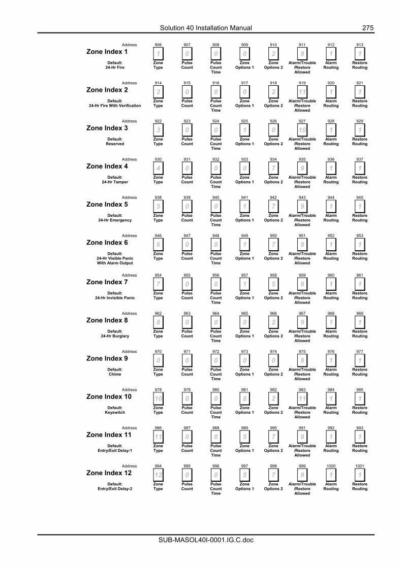
Solution 40 Installation Manual 275
SUB-MASOL40I-0001.IG.C.doc
Address 906 907 908 909 910 911 912 913
Zone Index 1 1 0 0 0 2 9 1 1 Default:
24-Hr Fire Zone Type
Pulse Count
Pulse Count Time
Zone Options 1
Zone Options 2
Alarm/Trouble/Restore Allowed
Alarm Routing
Restore Routing
Address 914 915 916 917 918 919 920 921
Zone Index 2 2 0 0 0 2 11 1 1 Default:
24-Hr Fire With Verification Zone Type
Pulse Count
Pulse Count Time
Zone Options 1
Zone Options 2
Alarm/Trouble/Restore Allowed
Alarm Routing
Restore Routing
Address 922 923 924 925 926 927 928 929
Zone Index 3 3 0 0 1 0 10 1 1 Default:
Reserved Zone Type
Pulse Count
Pulse Count Time
Zone Options 1
Zone Options 2
Alarm/Trouble/Restore Allowed
Alarm Routing
Restore Routing
Address 930 931 932 933 934 935 936 937
Zone Index 4 4 0 0 0 7 9 1 1 Default:
24-Hr Tamper Zone Type
Pulse Count
Pulse Count Time
Zone Options 1
Zone Options 2
Alarm/Trouble/Restore Allowed
Alarm Routing
Restore Routing
Address 938 939 940 941 942 943 944 945
Zone Index 5 5 0 0 1 7 9 1 1 Default:
24-Hr Emergency Zone Type
Pulse Count
Pulse Count Time
Zone Options 1
Zone Options 2
Alarm/Trouble/Restore Allowed
Alarm Routing
Restore Routing
Address 946 947 948 949 950 951 952 953
Zone Index 6 6 0 0 1 7 9 1 1 Default:
24-Hr Visible Panic With Alarm Output
Zone Type
Pulse Count
Pulse Count Time
Zone Options 1
Zone Options 2
Alarm/Trouble/Restore Allowed
Alarm Routing
Restore Routing
Address 954 955 956 957 958 959 960 961
Zone Index 7 7 0 0 1 5 9 1 1 Default:
24-Hr Invisible Panic Zone Type
Pulse Count
Pulse Count Time
Zone Options 1
Zone Options 2
Alarm/Trouble/Restore Allowed
Alarm Routing
Restore Routing
Address 962 963 964 965 966 967 968 969
Zone Index 8 8 0 0 0 2 9 1 1 Default:
24-Hr Burglary Zone Type
Pulse Count
Pulse Count Time
Zone Options 1
Zone Options 2
Alarm/Trouble/Restore Allowed
Alarm Routing
Restore Routing
Address 970 971 972 973 974 975 976 977
Zone Index 9 0 0 0 0 0 9 1 1 Default:
Chime Zone Type
Pulse Count
Pulse Count Time
Zone Options 1
Zone Options 2
Alarm/Trouble/Restore Allowed
Alarm Routing
Restore Routing
Address 978 979 980 981 982 983 984 985
Zone Index 10 10 0 0 8 2 11 1 1 Default:
Keyswitch Zone Type
Pulse Count
Pulse Count Time
Zone Options 1
Zone Options 2
Alarm/Trouble/Restore Allowed
Alarm Routing
Restore Routing
Address 986 987 988 989 990 991 992 993
Zone Index 11 11 0 0 5 7 9 1 1 Default:
Entry/Exit Delay-1 Zone Type
Pulse Count
Pulse Count Time
Zone Options 1
Zone Options 2
Alarm/Trouble/Restore Allowed
Alarm Routing
Restore Routing
Address 994 995 996 997 998 999 1000 1001
Zone Index 12 12 0 0 5 7 9 1 1 Default:
Entry/Exit Delay-2 Zone Type
Pulse Count
Pulse Count Time
Zone Options 1
Zone Options 2
Alarm/Trouble/Restore Allowed
Alarm Routing
Restore Routing
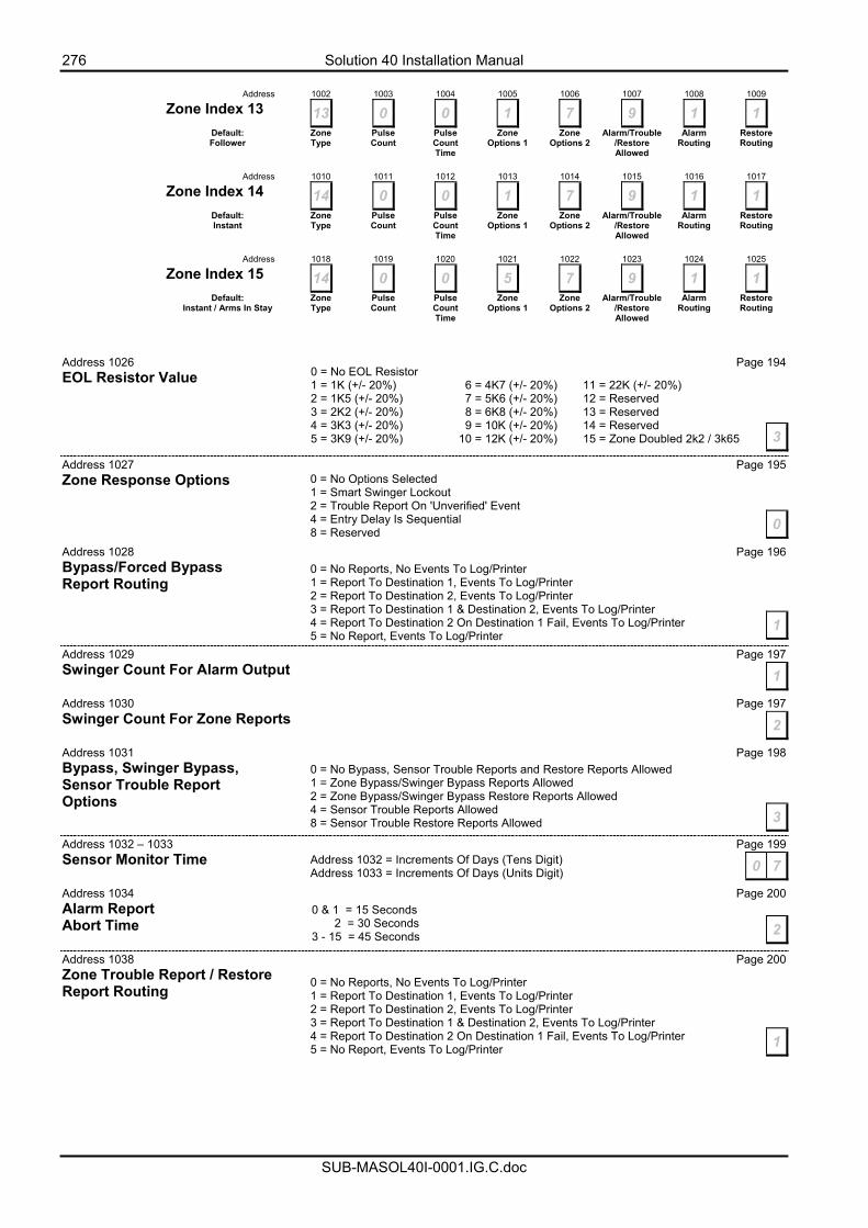
276 Solution 40 Installation Manual
SUB-MASOL40I-0001.IG.C.doc
Address 1002 1003 1004 1005 1006 1007 1008 1009
Zone Index 13 13 0 0 1 7 9 1 1 Default:
Follower Zone Type
Pulse Count
Pulse Count Time
Zone Options 1
Zone Options 2
Alarm/Trouble/Restore Allowed
Alarm Routing
Restore Routing
Address 1010 1011 1012 1013 1014 1015 1016 1017
Zone Index 14 14 0 0 1 7 9 1 1 Default:
Instant Zone Type
Pulse Count
Pulse Count Time
Zone Options 1
Zone Options 2
Alarm/Trouble/Restore Allowed
Alarm Routing
Restore Routing
Address 1018 1019 1020 1021 1022 1023 1024 1025
Zone Index 15 14 0 0 5 7 9 1 1 Default:
Instant / Arms In Stay Zone Type
Pulse Count
Pulse Count Time
Zone Options 1
Zone Options 2
Alarm/Trouble/Restore Allowed
Alarm Routing
Restore Routing
Address 1026 Page 194 EOL Resistor Value
Address 1027 Page 195 Zone Response Options Address 1028 Page 196 Bypass/Forced Bypass Report Routing Address 1029 Page 197 Swinger Count For Alarm Output Address 1030 Page 197 Swinger Count For Zone Reports Address 1031 Page 198 Bypass, Swinger Bypass, Sensor Trouble Report Options
Address 1032 – 1033 Page 199 Sensor Monitor Time Address 1034 Page 200 Alarm Report Abort Time Address 1038 Page 200 Zone Trouble Report / Restore Report Routing
0 = No EOL Resistor 1 = 1K (+/- 20%) 6 = 4K7 (+/- 20%) 11 = 22K (+/- 20%) 2 = 1K5 (+/- 20%) 7 = 5K6 (+/- 20%) 12 = Reserved 3 = 2K2 (+/- 20%) 8 = 6K8 (+/- 20%) 13 = Reserved 4 = 3K3 (+/- 20%) 9 = 10K (+/- 20%) 14 = Reserved 5 = 3K9 (+/- 20%) 10 = 12K (+/- 20%) 15 = Zone Doubled 2k2 / 3k65 3
0 = No Options Selected 1 = Smart Swinger Lockout 2 = Trouble Report On 'Unverified' Event 4 = Entry Delay Is Sequential 8 = Reserved 0
0 = No Reports, No Events To Log/Printer 1 = Report To Destination 1, Events To Log/Printer 2 = Report To Destination 2, Events To Log/Printer 3 = Report To Destination 1 & Destination 2, Events To Log/Printer 4 = Report To Destination 2 On Destination 1 Fail, Events To Log/Printer 5 = No Report, Events To Log/Printer
1
1
2
0 = No Bypass, Sensor Trouble Reports and Restore Reports Allowed 1 = Zone Bypass/Swinger Bypass Reports Allowed 2 = Zone Bypass/Swinger Bypass Restore Reports Allowed 4 = Sensor Trouble Reports Allowed 8 = Sensor Trouble Restore Reports Allowed 3
Address 1032 = Increments Of Days (Tens Digit) Address 1033 = Increments Of Days (Units Digit) 0 7
0 & 1 = 15 Seconds 2 = 30 Seconds 3 - 15 = 45 Seconds 2
0 = No Reports, No Events To Log/Printer 1 = Report To Destination 1, Events To Log/Printer 2 = Report To Destination 2, Events To Log/Printer 3 = Report To Destination 1 & Destination 2, Events To Log/Printer 4 = Report To Destination 2 On Destination 1 Fail, Events To Log/Printer 5 = No Report, Events To Log/Printer 1
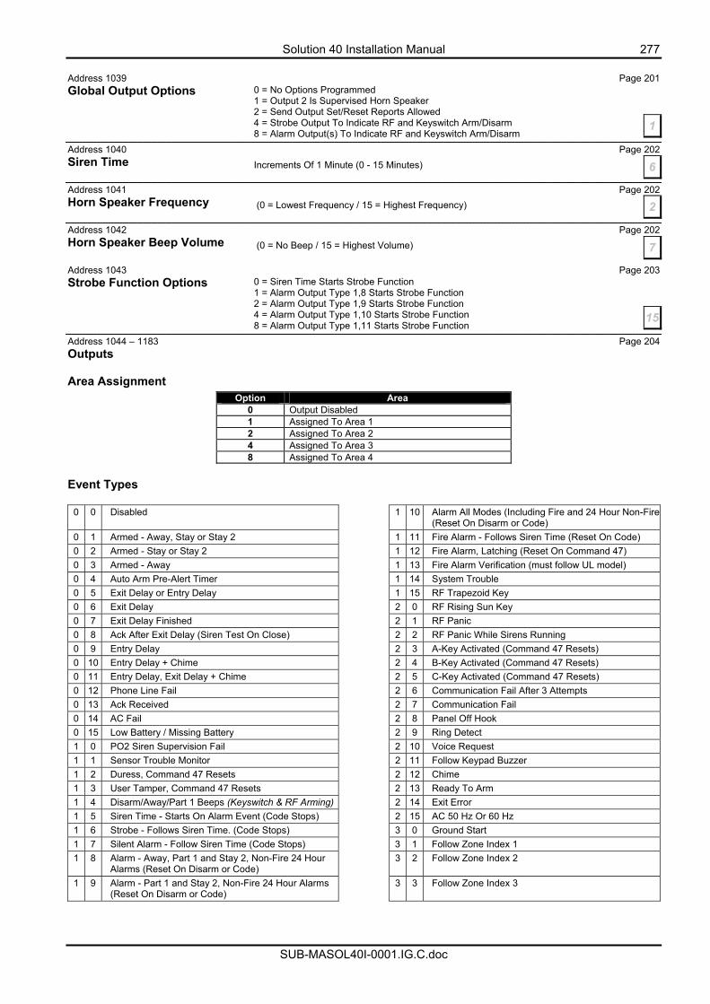
Solution 40 Installation Manual 277
SUB-MASOL40I-0001.IG.C.doc
Address 1039 Page 201 Global Output Options Address 1040 Page 202 Siren Time Address 1041 Page 202 Horn Speaker Frequency Address 1042 Page 202 Horn Speaker Beep Volume Address 1043 Page 203 Strobe Function Options Address 1044 – 1183 Page 204 Outputs Area Assignment
Option Area 0 Output Disabled 1 Assigned To Area 1 2 Assigned To Area 2 4 Assigned To Area 3 8 Assigned To Area 4
Event Types
0 0 Disabled 1 10 Alarm All Modes (Including Fire and 24 Hour Non-Fire (Reset On Disarm or Code)
0 1 Armed - Away, Stay or Stay 2 1 11 Fire Alarm - Follows Siren Time (Reset On Code) 0 2 Armed - Stay or Stay 2 1 12 Fire Alarm, Latching (Reset On Command 47) 0 3 Armed - Away 1 13 Fire Alarm Verification (must follow UL model) 0 4 Auto Arm Pre-Alert Timer 1 14 System Trouble 0 5 Exit Delay or Entry Delay 1 15 RF Trapezoid Key 0 6 Exit Delay 2 0 RF Rising Sun Key 0 7 Exit Delay Finished 2 1 RF Panic 0 8 Ack After Exit Delay (Siren Test On Close) 2 2 RF Panic While Sirens Running 0 9 Entry Delay 2 3 A-Key Activated (Command 47 Resets) 0 10 Entry Delay + Chime 2 4 B-Key Activated (Command 47 Resets) 0 11 Entry Delay, Exit Delay + Chime 2 5 C-Key Activated (Command 47 Resets) 0 12 Phone Line Fail 2 6 Communication Fail After 3 Attempts 0 13 Ack Received 2 7 Communication Fail 0 14 AC Fail 2 8 Panel Off Hook 0 15 Low Battery / Missing Battery 2 9 Ring Detect 1 0 PO2 Siren Supervision Fail 2 10 Voice Request 1 1 Sensor Trouble Monitor 2 11 Follow Keypad Buzzer 1 2 Duress, Command 47 Resets 2 12 Chime 1 3 User Tamper, Command 47 Resets 2 13 Ready To Arm 1 4 Disarm/Away/Part 1 Beeps (Keyswitch & RF Arming) 2 14 Exit Error 1 5 Siren Time - Starts On Alarm Event (Code Stops) 2 15 AC 50 Hz Or 60 Hz 1 6 Strobe - Follows Siren Time. (Code Stops) 3 0 Ground Start 1 7 Silent Alarm - Follow Siren Time (Code Stops) 3 1 Follow Zone Index 1 1 8 Alarm - Away, Part 1 and Stay 2, Non-Fire 24 Hour
Alarms (Reset On Disarm or Code) 3 2 Follow Zone Index 2
1 9 Alarm - Part 1 and Stay 2, Non-Fire 24 Hour Alarms (Reset On Disarm or Code)
3 3 Follow Zone Index 3
0 = No Options Programmed 1 = Output 2 Is Supervised Horn Speaker 2 = Send Output Set/Reset Reports Allowed 4 = Strobe Output To Indicate RF and Keyswitch Arm/Disarm 8 = Alarm Output(s) To Indicate RF and Keyswitch Arm/Disarm
1
6Increments Of 1 Minute (0 - 15 Minutes)
2 (0 = Lowest Frequency / 15 = Highest Frequency)
(0 = No Beep / 15 = Highest Volume) 7
0 = Siren Time Starts Strobe Function 1 = Alarm Output Type 1,8 Starts Strobe Function 2 = Alarm Output Type 1,9 Starts Strobe Function 4 = Alarm Output Type 1,10 Starts Strobe Function 8 = Alarm Output Type 1,11 Starts Strobe Function
15
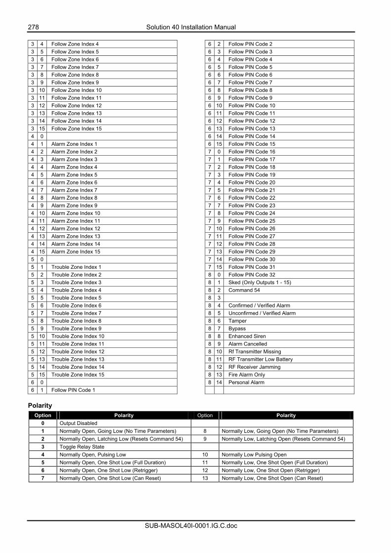
278 Solution 40 Installation Manual
SUB-MASOL40I-0001.IG.C.doc
3 4 Follow Zone Index 4 6 2 Follow PIN Code 2 3 5 Follow Zone Index 5 6 3 Follow PIN Code 3 3 6 Follow Zone Index 6 6 4 Follow PIN Code 4 3 7 Follow Zone Index 7 6 5 Follow PIN Code 5 3 8 Follow Zone Index 8 6 6 Follow PIN Code 6 3 9 Follow Zone Index 9 6 7 Follow PIN Code 7 3 10 Follow Zone Index 10 6 8 Follow PIN Code 8 3 11 Follow Zone Index 11 6 9 Follow PIN Code 9 3 12 Follow Zone Index 12 6 10 Follow PIN Code 10 3 13 Follow Zone Index 13 6 11 Follow PIN Code 11 3 14 Follow Zone Index 14 6 12 Follow PIN Code 12 3 15 Follow Zone Index 15 6 13 Follow PIN Code 13 4 0 6 14 Follow PIN Code 14 4 1 Alarm Zone Index 1 6 15 Follow PIN Code 15 4 2 Alarm Zone Index 2 7 0 Follow PIN Code 16 4 3 Alarm Zone Index 3 7 1 Follow PIN Code 17 4 4 Alarm Zone Index 4 7 2 Follow PIN Code 18 4 5 Alarm Zone Index 5 7 3 Follow PIN Code 19 4 6 Alarm Zone Index 6 7 4 Follow PIN Code 20 4 7 Alarm Zone Index 7 7 5 Follow PIN Code 21 4 8 Alarm Zone Index 8 7 6 Follow PIN Code 22 4 9 Alarm Zone Index 9 7 7 Follow PIN Code 23 4 10 Alarm Zone Index 10 7 8 Follow PIN Code 24 4 11 Alarm Zone Index 11 7 9 Follow PIN Code 25 4 12 Alarm Zone Index 12 7 10 Follow PIN Code 26 4 13 Alarm Zone Index 13 7 11 Follow PIN Code 27 4 14 Alarm Zone Index 14 7 12 Follow PIN Code 28 4 15 Alarm Zone Index 15 7 13 Follow PIN Code 29 5 0 7 14 Follow PIN Code 30 5 1 Trouble Zone Index 1 7 15 Follow PIN Code 31 5 2 Trouble Zone Index 2 8 0 Follow PIN Code 32 5 3 Trouble Zone Index 3 8 1 Sked (Only Outputs 1 - 15) 5 4 Trouble Zone Index 4 8 2 Command 54 5 5 Trouble Zone Index 5 8 3 5 6 Trouble Zone Index 6 8 4 Confirmed / Verified Alarm 5 7 Trouble Zone Index 7 8 5 Unconfirmed / Verified Alarm 5 8 Trouble Zone Index 8 8 6 Tamper 5 9 Trouble Zone Index 9 8 7 Bypass 5 10 Trouble Zone Index 10 8 8 Enhanced Siren 5 11 Trouble Zone Index 11 8 9 Alarm Cancelled 5 12 Trouble Zone Index 12 8 10 Rf Transmitter Missing 5 13 Trouble Zone Index 13 8 11 RF Transmitter Low Battery 5 14 Trouble Zone Index 14 8 12 RF Receiver Jamming 5 15 Trouble Zone Index 15 8 13 Fire Alarm Only 6 0 8 14 Personal Alarm 6 1 Follow PIN Code 1
Polarity
Option Polarity Option Polarity 0 Output Disabled 1 Normally Open, Going Low (No Time Parameters) 8 Normally Low, Going Open (No Time Parameters) 2 Normally Open, Latching Low (Resets Command 54) 9 Normally Low, Latching Open (Resets Command 54) 3 Toggle Relay State 4 Normally Open, Pulsing Low 10 Normally Low Pulsing Open 5 Normally Open, One Shot Low (Full Duration) 11 Normally Low, One Shot Open (Full Duration) 6 Normally Open, One Shot Low (Retrigger) 12 Normally Low, One Shot Open (Retrigger) 7 Normally Open, One Shot Low (Can Reset) 13 Normally Low, One Shot Open (Can Reset)
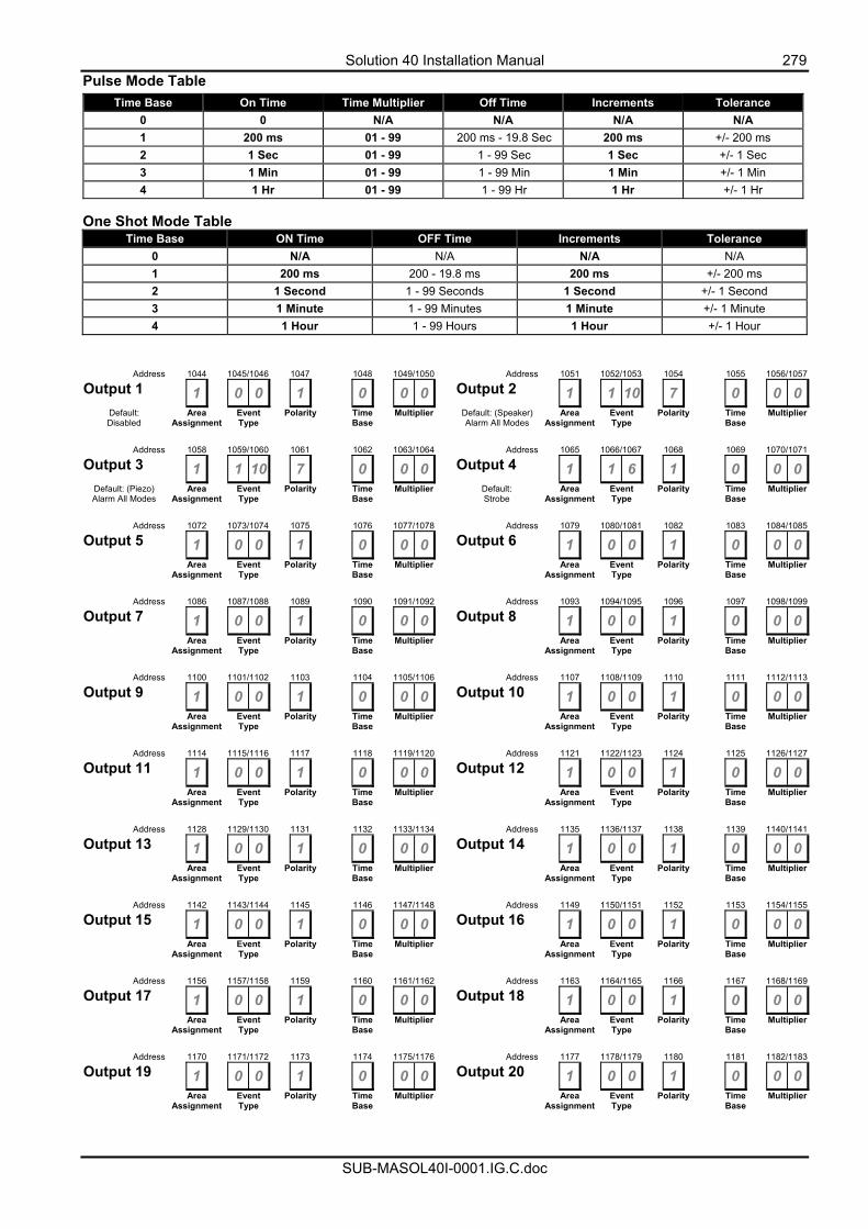
Solution 40 Installation Manual 279
SUB-MASOL40I-0001.IG.C.doc
Pulse Mode Table Time Base On Time Time Multiplier Off Time Increments Tolerance
0 0 N/A N/A N/A N/A 1 200 ms 01 - 99 200 ms - 19.8 Sec 200 ms +/- 200 ms 2 1 Sec 01 - 99 1 - 99 Sec 1 Sec +/- 1 Sec 3 1 Min 01 - 99 1 - 99 Min 1 Min +/- 1 Min 4 1 Hr 01 - 99 1 - 99 Hr 1 Hr +/- 1 Hr
One Shot Mode Table
Time Base ON Time OFF Time Increments Tolerance 0 N/A N/A N/A N/A 1 200 ms 200 - 19.8 ms 200 ms +/- 200 ms 2 1 Second 1 - 99 Seconds 1 Second +/- 1 Second 3 1 Minute 1 - 99 Minutes 1 Minute +/- 1 Minute 4 1 Hour 1 - 99 Hours 1 Hour +/- 1 Hour
Address 1044 1045/1046 1047 1048 1049/1050 Address 1051 1052/1053 1054 1055 1056/1057
Output 1 1 0 0 1 0 0 0 Output 2 1 1 10 7 0 0 0Default: Disabled
Area Assignment
Event Type
Polarity Time Base
Multiplier Default: (Speaker) Alarm All Modes
Area Assignment
Event Type
Polarity Time Base
Multiplier
Address 1058 1059/1060 1061 1062 1063/1064 Address 1065 1066/1067 1068 1069 1070/1071
Output 3 1 1 10 7 0 0 0 Output 4 1 1 6 1 0 0 0Default: (Piezo) Alarm All Modes
Area Assignment
Event Type
Polarity Time Base
Multiplier Default: Strobe
Area Assignment
Event Type
Polarity Time Base
Multiplier
Address 1072 1073/1074 1075 1076 1077/1078 Address 1079 1080/1081 1082 1083 1084/1085
Output 5 1 0 0 1 0 0 0 Output 6 1 0 0 1 0 0 0 Area
Assignment Event Type
Polarity Time Base
Multiplier Area Assignment
Event Type
Polarity Time Base
Multiplier
Address 1086 1087/1088 1089 1090 1091/1092 Address 1093 1094/1095 1096 1097 1098/1099
Output 7 1 0 0 1 0 0 0 Output 8 1 0 0 1 0 0 0 Area
Assignment Event Type
Polarity Time Base
Multiplier Area Assignment
Event Type
Polarity Time Base
Multiplier
Address 1100 1101/1102 1103 1104 1105/1106 Address 1107 1108/1109 1110 1111 1112/1113
Output 9 1 0 0 1 0 0 0 Output 10 1 0 0 1 0 0 0 Area
Assignment Event Type
Polarity Time Base
Multiplier Area Assignment
Event Type
Polarity Time Base
Multiplier
Address 1114 1115/1116 1117 1118 1119/1120 Address 1121 1122/1123 1124 1125 1126/1127
Output 11 1 0 0 1 0 0 0 Output 12 1 0 0 1 0 0 0 Area
Assignment Event Type
Polarity Time Base
Multiplier Area Assignment
Event Type
Polarity Time Base
Multiplier
Address 1128 1129/1130 1131 1132 1133/1134 Address 1135 1136/1137 1138 1139 1140/1141
Output 13 1 0 0 1 0 0 0 Output 14 1 0 0 1 0 0 0 Area
Assignment Event Type
Polarity Time Base
Multiplier Area Assignment
Event Type
Polarity Time Base
Multiplier
Address 1142 1143/1144 1145 1146 1147/1148 Address 1149 1150/1151 1152 1153 1154/1155
Output 15 1 0 0 1 0 0 0 Output 16 1 0 0 1 0 0 0 Area
Assignment Event Type
Polarity Time Base
Multiplier Area Assignment
Event Type
Polarity Time Base
Multiplier
Address 1156 1157/1158 1159 1160 1161/1162 Address 1163 1164/1165 1166 1167 1168/1169
Output 17 1 0 0 1 0 0 0 Output 18 1 0 0 1 0 0 0 Area
Assignment Event Type
Polarity Time Base
Multiplier Area Assignment
Event Type
Polarity Time Base
Multiplier
Address 1170 1171/1172 1173 1174 1175/1176 Address 1177 1178/1179 1180 1181 1182/1183
Output 19 1 0 0 1 0 0 0 Output 20 1 0 0 1 0 0 0 Area
Assignment Event Type
Polarity Time Base
Multiplier Area Assignment
Event Type
Polarity Time Base
Multiplier
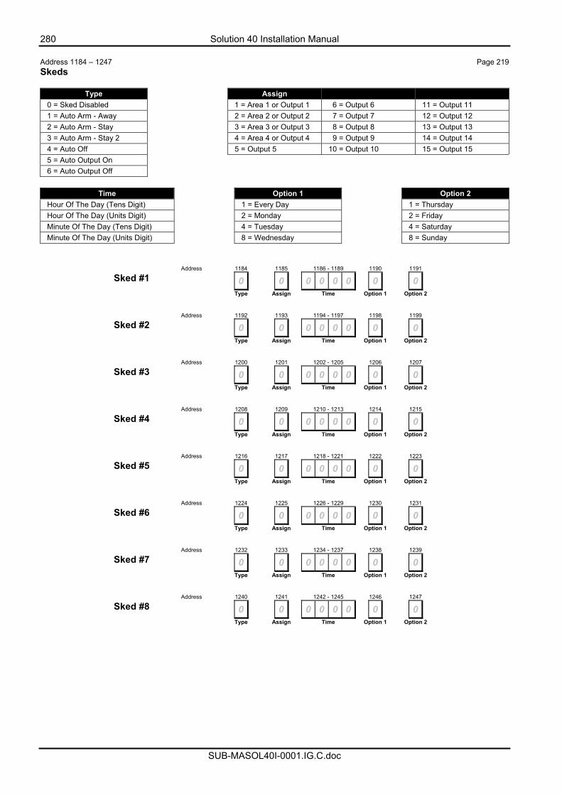
280 Solution 40 Installation Manual
SUB-MASOL40I-0001.IG.C.doc
Address 1184 – 1247 Page 219 Skeds
Type Assign 0 = Sked Disabled 1 = Area 1 or Output 1 6 = Output 6 11 = Output 11 1 = Auto Arm - Away 2 = Area 2 or Output 2 7 = Output 7 12 = Output 12 2 = Auto Arm - Stay 3 = Area 3 or Output 3 8 = Output 8 13 = Output 13 3 = Auto Arm - Stay 2 4 = Area 4 or Output 4 9 = Output 9 14 = Output 14 4 = Auto Off 5 = Output 5 10 = Output 10 15 = Output 15 5 = Auto Output On 6 = Auto Output Off
Time Option 1 Option 2
Hour Of The Day (Tens Digit) 1 = Every Day 1 = Thursday Hour Of The Day (Units Digit) 2 = Monday 2 = Friday Minute Of The Day (Tens Digit) 4 = Tuesday 4 = Saturday Minute Of The Day (Units Digit) 8 = Wednesday 8 = Sunday
Address 1184 1185 1186 - 1189 1190 1191
Sked #1 0 0 0 0 0 0 0 0 Type Assign Time Option 1 Option 2
Address 1192 1193 1194 - 1197 1198 1199
Sked #2 0 0 0 0 0 0 0 0 Type Assign Time Option 1 Option 2
Address 1200 1201 1202 - 1205 1206 1207
Sked #3 0 0 0 0 0 0 0 0 Type Assign Time Option 1 Option 2
Address 1208 1209 1210 - 1213 1214 1215
Sked #4 0 0 0 0 0 0 0 0 Type Assign Time Option 1 Option 2
Address 1216 1217 1218 - 1221 1222 1223
Sked #5 0 0 0 0 0 0 0 0 Type Assign Time Option 1 Option 2
Address 1224 1225 1226 - 1229 1230 1231
Sked #6 0 0 0 0 0 0 0 0 Type Assign Time Option 1 Option 2
Address 1232 1233 1234 - 1237 1238 1239
Sked #7 0 0 0 0 0 0 0 0 Type Assign Time Option 1 Option 2
Address 1240 1241 1242 - 1245 1246 1247
Sked #8 0 0 0 0 0 0 0 0 Type Assign Time Option 1 Option 2
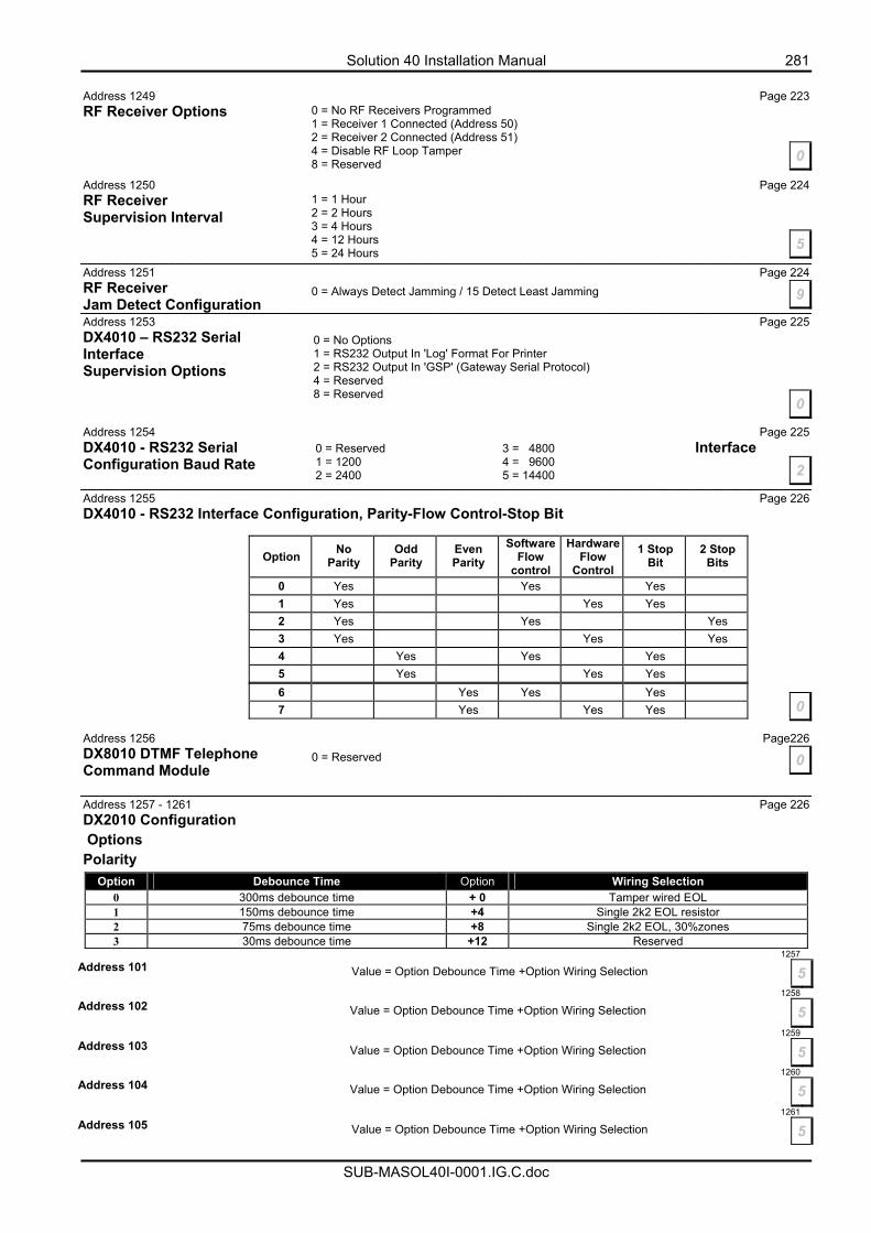
Solution 40 Installation Manual 281
SUB-MASOL40I-0001.IG.C.doc
Address 1249 Page 223 RF Receiver Options Address 1250 Page 224 RF Receiver Supervision Interval Address 1251 Page 224 RF Receiver Jam Detect Configuration Address 1253 Page 225 DX4010 – RS232 Serial Interface Supervision Options
Address 1254 Page 225 DX4010 - RS232 Serial Interface Configuration Baud Rate Address 1255 Page 226 DX4010 - RS232 Interface Configuration, Parity-Flow Control-Stop Bit
Option No
Parity Odd
Parity Even Parity
SoftwareFlow
control
Hardware Flow
Control
1 Stop Bit
2 Stop Bits
0 Yes Yes Yes 1 Yes Yes Yes 2 Yes Yes Yes 3 Yes Yes Yes 4 Yes Yes Yes 5 Yes Yes Yes 6 Yes Yes Yes 7 Yes Yes Yes
Address 1256 Page226 DX8010 DTMF Telephone Command Module Address 1257 - 1261 Page 226 DX2010 Configuration Options Polarity
Option Debounce Time Option Wiring Selection 0 300ms debounce time + 0 Tamper wired EOL 1 150ms debounce time +4 Single 2k2 EOL resistor 2 75ms debounce time +8 Single 2k2 EOL, 30%zones 3 30ms debounce time +12 Reserved
1257Address 101
Value = Option Debounce Time +Option Wiring Selection 51258
Address 102
Value = Option Debounce Time +Option Wiring Selection 5 1259
Address 103 Value = Option Debounce Time +Option Wiring Selection 5 1260
Address 104 Value = Option Debounce Time +Option Wiring Selection 5 1261
Address 105 Value = Option Debounce Time +Option Wiring Selection 5
0 = No RF Receivers Programmed 1 = Receiver 1 Connected (Address 50) 2 = Receiver 2 Connected (Address 51) 4 = Disable RF Loop Tamper 8 = Reserved 0
1 = 1 Hour 2 = 2 Hours 3 = 4 Hours 4 = 12 Hours 5 = 24 Hours
5
0 = Always Detect Jamming / 15 Detect Least Jamming 9
0 = No Options 1 = RS232 Output In 'Log' Format For Printer 2 = RS232 Output In 'GSP' (Gateway Serial Protocol) 4 = Reserved 8 = Reserved
0
0 = Reserved 3 = 4800 1 = 1200 4 = 9600 2 = 2400 5 = 14400 2
0
0 = Reserved 0
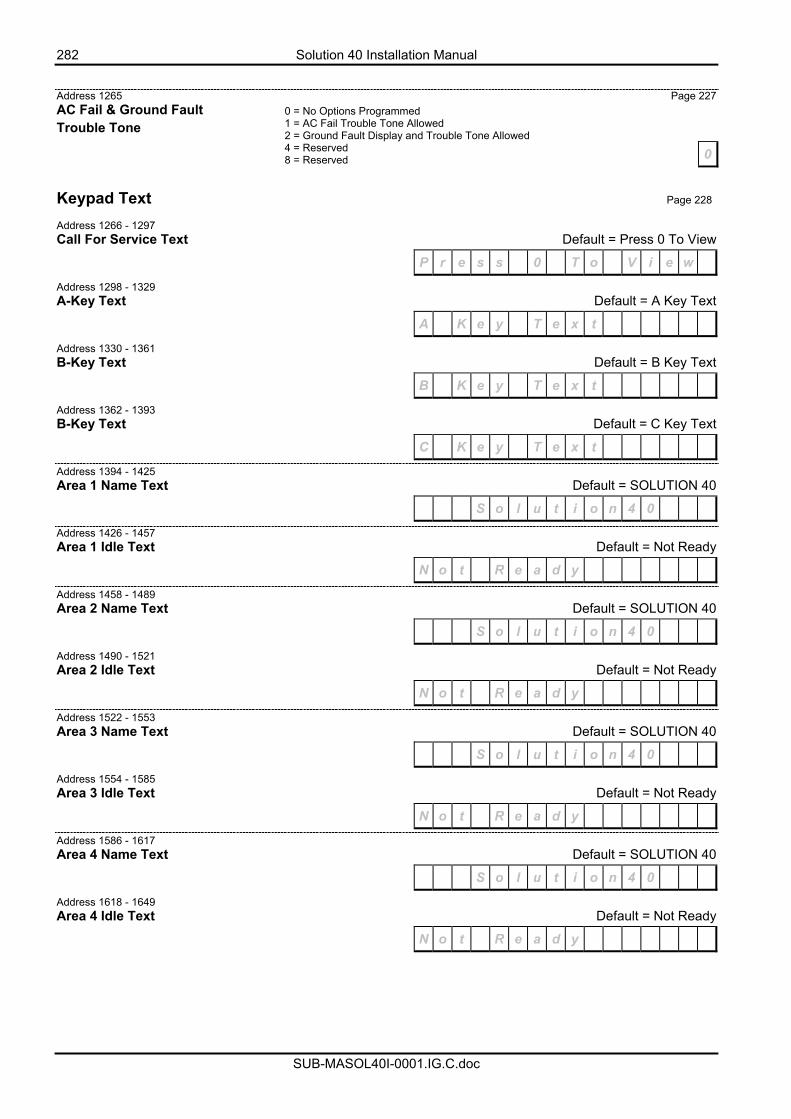
282 Solution 40 Installation Manual
SUB-MASOL40I-0001.IG.C.doc
Address 1265 Page 227 AC Fail & Ground Fault Trouble Tone
Keypad Text Page 228
Address 1266 - 1297 Call For Service Text Default = Press 0 To View
P r e s s 0 T o V i e w
Address 1298 - 1329 A-Key Text Default = A Key Text
A K e y T e x t
Address 1330 - 1361 B-Key Text Default = B Key Text
B K e y T e x t
Address 1362 - 1393 B-Key Text Default = C Key Text
C K e y T e x t
Address 1394 - 1425 Area 1 Name Text Default = SOLUTION 40
S o l u t i o n 4 0
Address 1426 - 1457 Area 1 Idle Text Default = Not Ready
N o t R e a d y
Address 1458 - 1489 Area 2 Name Text Default = SOLUTION 40
S o l u t i o n 4 0
Address 1490 - 1521 Area 2 Idle Text Default = Not Ready
N o t R e a d y
Address 1522 - 1553 Area 3 Name Text Default = SOLUTION 40
S o l u t i o n 4 0
Address 1554 - 1585 Area 3 Idle Text Default = Not Ready
N o t R e a d y
Address 1586 - 1617 Area 4 Name Text Default = SOLUTION 40
S o l u t i o n 4 0
Address 1618 - 1649 Area 4 Idle Text Default = Not Ready
N o t R e a d y
0
0 = No Options Programmed 1 = AC Fail Trouble Tone Allowed 2 = Ground Fault Display and Trouble Tone Allowed 4 = Reserved 8 = Reserved
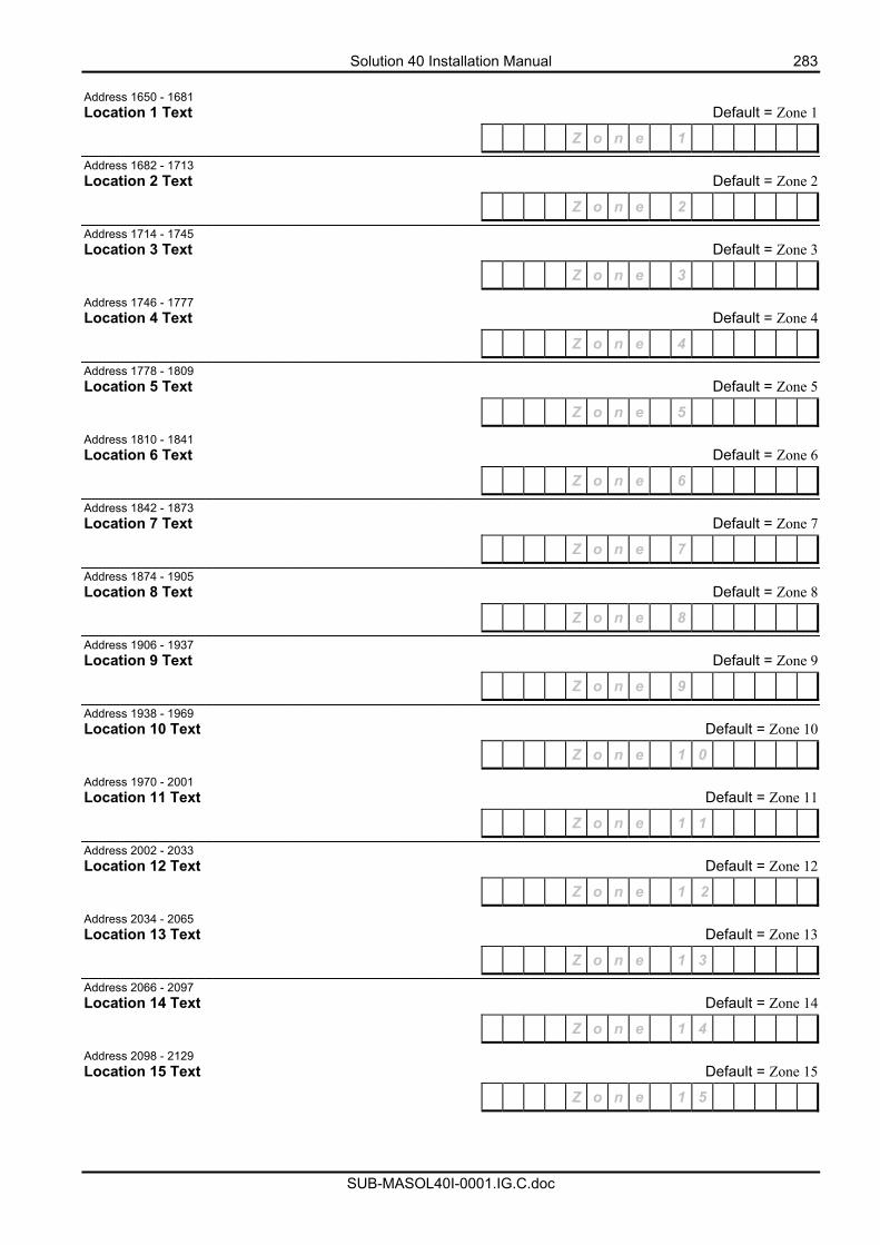
Solution 40 Installation Manual 283
SUB-MASOL40I-0001.IG.C.doc
Address 1650 - 1681 Location 1 Text Default = Zone 1
Z o n e 1
Address 1682 - 1713 Location 2 Text Default = Zone 2
Z o n e 2
Address 1714 - 1745 Location 3 Text Default = Zone 3
Z o n e 3
Address 1746 - 1777 Location 4 Text Default = Zone 4
Z o n e 4
Address 1778 - 1809 Location 5 Text Default = Zone 5
Z o n e 5
Address 1810 - 1841 Location 6 Text Default = Zone 6
Z o n e 6
Address 1842 - 1873 Location 7 Text Default = Zone 7
Z o n e 7
Address 1874 - 1905 Location 8 Text Default = Zone 8
Z o n e 8
Address 1906 - 1937 Location 9 Text Default = Zone 9
Z o n e 9
Address 1938 - 1969 Location 10 Text Default = Zone 10
Z o n e 1 0
Address 1970 - 2001 Location 11 Text Default = Zone 11
Z o n e 1 1
Address 2002 - 2033 Location 12 Text Default = Zone 12
Z o n e 1 2
Address 2034 - 2065 Location 13 Text Default = Zone 13
Z o n e 1 3
Address 2066 - 2097 Location 14 Text Default = Zone 14
Z o n e 1 4
Address 2098 - 2129 Location 15 Text Default = Zone 15
Z o n e 1 5
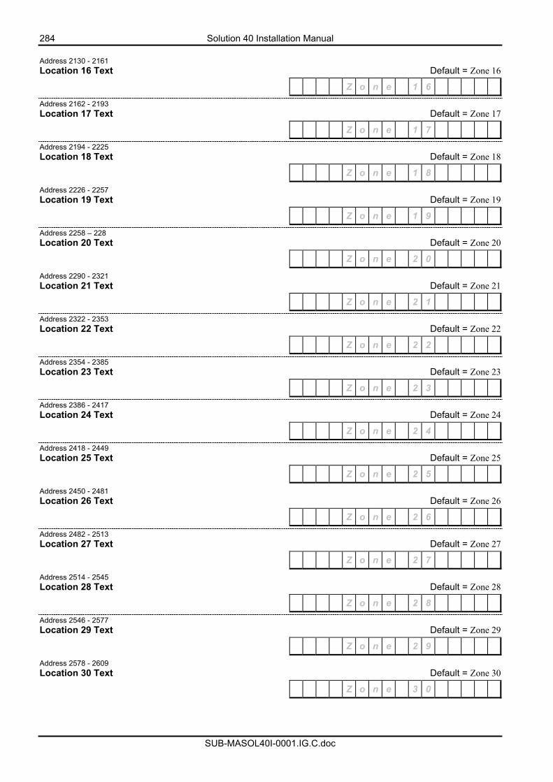
284 Solution 40 Installation Manual
SUB-MASOL40I-0001.IG.C.doc
Address 2130 - 2161 Location 16 Text Default = Zone 16
Z o n e 1 6
Address 2162 - 2193 Location 17 Text Default = Zone 17
Z o n e 1 7
Address 2194 - 2225 Location 18 Text Default = Zone 18
Z o n e 1 8
Address 2226 - 2257 Location 19 Text Default = Zone 19
Z o n e 1 9
Address 2258 – 228 Location 20 Text Default = Zone 20
Z o n e 2 0
Address 2290 - 2321 Location 21 Text Default = Zone 21
Z o n e 2 1
Address 2322 - 2353 Location 22 Text Default = Zone 22
Z o n e 2 2
Address 2354 - 2385 Location 23 Text Default = Zone 23
Z o n e 2 3
Address 2386 - 2417 Location 24 Text Default = Zone 24
Z o n e 2 4
Address 2418 - 2449 Location 25 Text Default = Zone 25
Z o n e 2 5
Address 2450 - 2481 Location 26 Text Default = Zone 26
Z o n e 2 6
Address 2482 - 2513 Location 27 Text Default = Zone 27
Z o n e 2 7
Address 2514 - 2545 Location 28 Text Default = Zone 28
Z o n e 2 8
Address 2546 - 2577 Location 29 Text Default = Zone 29
Z o n e 2 9
Address 2578 - 2609 Location 30 Text Default = Zone 30
Z o n e 3 0
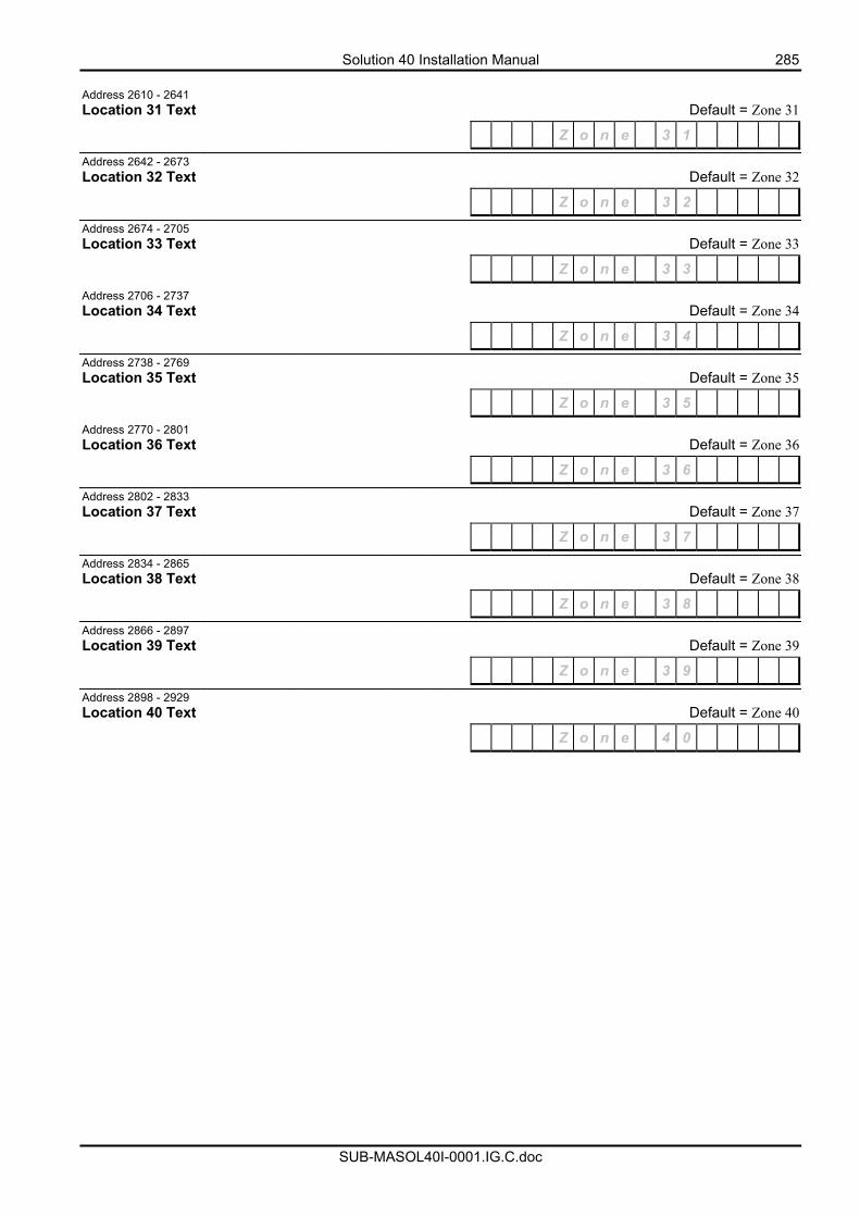
Solution 40 Installation Manual 285
SUB-MASOL40I-0001.IG.C.doc
Address 2610 - 2641 Location 31 Text Default = Zone 31
Z o n e 3 1
Address 2642 - 2673 Location 32 Text Default = Zone 32
Z o n e 3 2
Address 2674 - 2705 Location 33 Text Default = Zone 33
Z o n e 3 3
Address 2706 - 2737 Location 34 Text Default = Zone 34
Z o n e 3 4
Address 2738 - 2769 Location 35 Text Default = Zone 35
Z o n e 3 5
Address 2770 - 2801 Location 36 Text Default = Zone 36
Z o n e 3 6
Address 2802 - 2833 Location 37 Text Default = Zone 37
Z o n e 3 7
Address 2834 - 2865 Location 38 Text Default = Zone 38
Z o n e 3 8
Address 2866 - 2897 Location 39 Text Default = Zone 39
Z o n e 3 9
Address 2898 - 2929 Location 40 Text Default = Zone 40
Z o n e 4 0
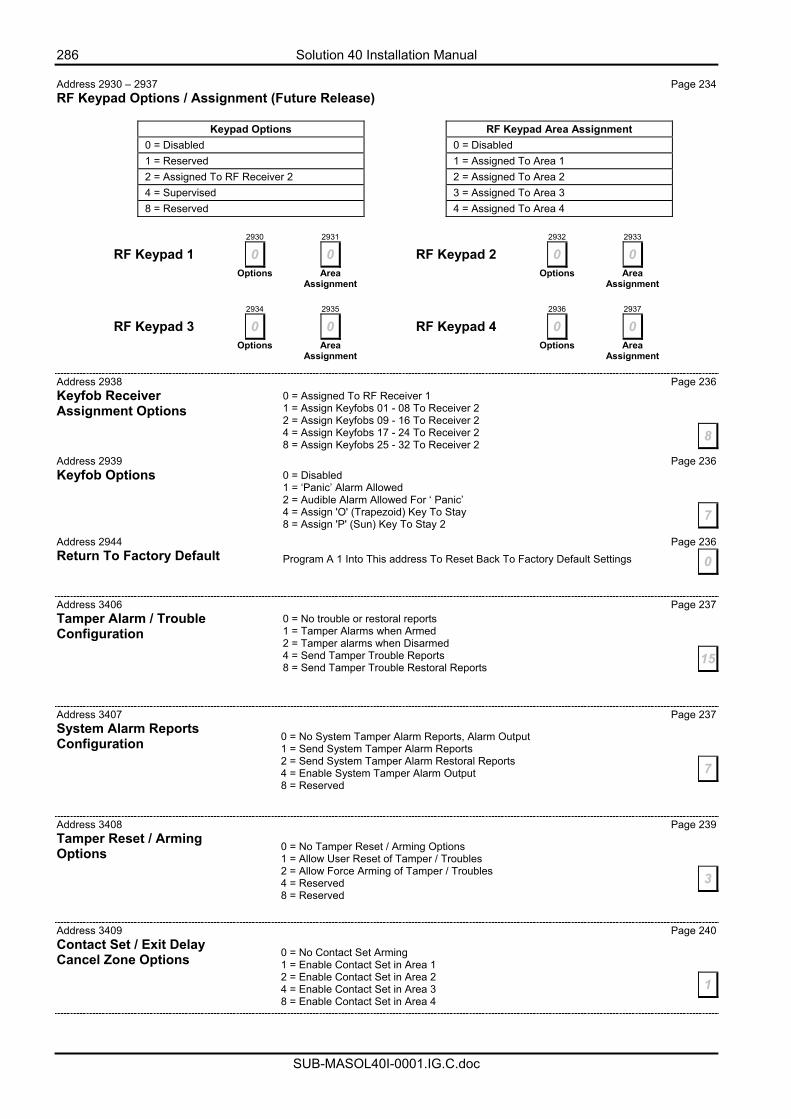
286 Solution 40 Installation Manual
SUB-MASOL40I-0001.IG.C.doc
Address 2930 – 2937 Page 234 RF Keypad Options / Assignment (Future Release)
2930 2931 2932 2933
RF Keypad 1 0 0 RF Keypad 2 0 0 Options Area
Assignment Options Area
Assignment
2934 2935 2936 2937
RF Keypad 3 0 0 RF Keypad 4 0 0 Options Area
Assignment Options Area
Assignment
Address 2938 Page 236 Keyfob Receiver Assignment Options Address 2939 Page 236 Keyfob Options Address 2944 Page 236 Return To Factory Default Address 3406 Page 237 Tamper Alarm / Trouble Configuration
Address 3407 Page 237 System Alarm Reports Configuration
Address 3408 Page 239 Tamper Reset / Arming Options
Address 3409 Page 240 Contact Set / Exit Delay Cancel Zone Options
RF Keypad Area Assignment 0 = Disabled 1 = Assigned To Area 1 2 = Assigned To Area 2 3 = Assigned To Area 3 4 = Assigned To Area 4
Keypad Options 0 = Disabled 1 = Reserved 2 = Assigned To RF Receiver 2 4 = Supervised 8 = Reserved
0 = Assigned To RF Receiver 1 1 = Assign Keyfobs 01 - 08 To Receiver 2 2 = Assign Keyfobs 09 - 16 To Receiver 2 4 = Assign Keyfobs 17 - 24 To Receiver 2 8 = Assign Keyfobs 25 - 32 To Receiver 2
8
0 = Disabled 1 = ‘Panic’ Alarm Allowed 2 = Audible Alarm Allowed For ‘ Panic’ 4 = Assign 'O' (Trapezoid) Key To Stay 8 = Assign 'P' (Sun) Key To Stay 2
7
Program A 1 Into This address To Reset Back To Factory Default Settings 0
0 = No trouble or restoral reports 1 = Tamper Alarms when Armed 2 = Tamper alarms when Disarmed 4 = Send Tamper Trouble Reports 8 = Send Tamper Trouble Restoral Reports
15
0 = No System Tamper Alarm Reports, Alarm Output 1 = Send System Tamper Alarm Reports 2 = Send System Tamper Alarm Restoral Reports 4 = Enable System Tamper Alarm Output 8 = Reserved
7
0 = No Tamper Reset / Arming Options 1 = Allow User Reset of Tamper / Troubles 2 = Allow Force Arming of Tamper / Troubles 4 = Reserved 8 = Reserved
3
0 = No Contact Set Arming 1 = Enable Contact Set in Area 1 2 = Enable Contact Set in Area 2 4 = Enable Contact Set in Area 3 8 = Enable Contact Set in Area 4
1
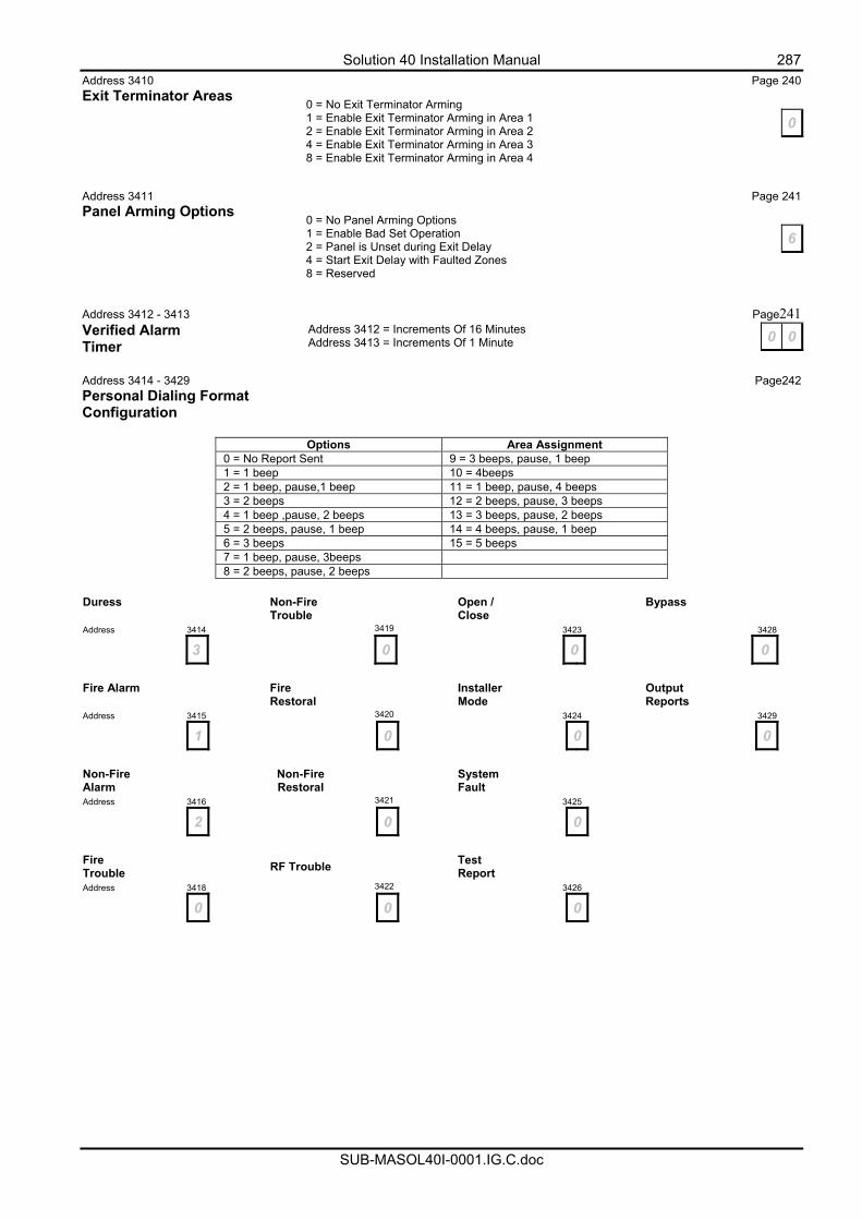
Solution 40 Installation Manual 287
SUB-MASOL40I-0001.IG.C.doc
Address 3410 Page 240 Exit Terminator Areas
Address 3411 Page 241 Panel Arming Options
Address 3412 - 3413 Page241 Verified Alarm Timer Address 3414 - 3429 Page242 Personal Dialing Format Configuration
Options Area Assignment 0 = No Report Sent 9 = 3 beeps, pause, 1 beep 1 = 1 beep 10 = 4beeps 2 = 1 beep, pause,1 beep 11 = 1 beep, pause, 4 beeps 3 = 2 beeps 12 = 2 beeps, pause, 3 beeps 4 = 1 beep ,pause, 2 beeps 13 = 3 beeps, pause, 2 beeps 5 = 2 beeps, pause, 1 beep 14 = 4 beeps, pause, 1 beep 6 = 3 beeps 15 = 5 beeps 7 = 1 beep, pause, 3beeps 8 = 2 beeps, pause, 2 beeps
Duress
Non-Fire Trouble
Open / Close
Bypass
Address 3414 3419 3423 3428
3 0 0 0
Fire Alarm Fire
Restoral Installer
Mode Output
Reports Address 3415 3420 3424 3429
1 0 0 0
Non-Fire Alarm
Non-Fire
Restoral System
Fault Address 3416 3421 3425
2 0 0
Fire Trouble
RF Trouble Test
Report Address 3418 3422 3426
0 0 0
0 = No Exit Terminator Arming 1 = Enable Exit Terminator Arming in Area 1 2 = Enable Exit Terminator Arming in Area 2 4 = Enable Exit Terminator Arming in Area 3 8 = Enable Exit Terminator Arming in Area 4
0
0 = No Panel Arming Options 1 = Enable Bad Set Operation 2 = Panel is Unset during Exit Delay 4 = Start Exit Delay with Faulted Zones 8 = Reserved
6
Address 3412 = Increments Of 16 Minutes Address 3413 = Increments Of 1 Minute 0 0
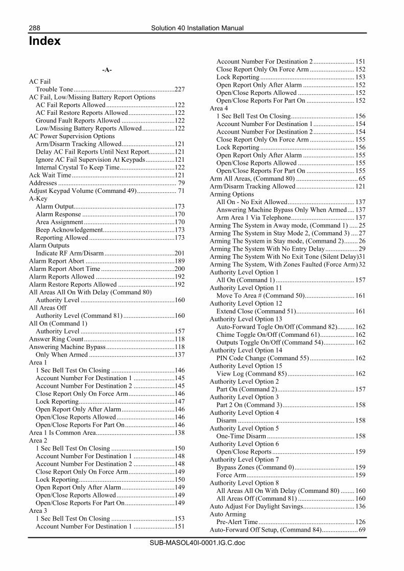
288 Solution 40 Installation Manual
SUB-MASOL40I-0001.IG.C.doc
Index
-A-
AC Fail Trouble Tone...........................................................227
AC Fail, Low/Missing Battery Report Options AC Fail Reports Allowed ........................................122 AC Fail Restore Reports Allowed...........................122 Ground Fault Reports Allowed ...............................122 Low/Missing Battery Reports Allowed...................122
AC Power Supervision Options Arm/Disarm Tracking Allowed...............................121 Delay AC Fail Reports Until Next Report...............121 Ignore AC Fail Supervision At Keypads.................121 Internal Crystal To Keep Time................................122
Ack Wait Time............................................................121 Addresses ..................................................................... 79 Adjust Keypad Volume (Command 49)....................... 71 A-Key
Alarm Output...........................................................173 Alarm Response ......................................................170 Area Assignment .....................................................170 Beep Acknowledgement..........................................173 Reporting Allowed ..................................................173
Alarm Outputs Indicate RF Arm/Disarm.........................................201
Alarm Report Abort ....................................................189 Alarm Report Abort Time ...........................................200 Alarm Reports Allowed ..............................................192 Alarm Restore Reports Allowed .................................192 All Areas All On With Delay (Command 80)
Authority Level .......................................................160 All Areas Off
Authority Level (Command 81) ..............................160 All On (Command 1)
Authority Level .......................................................157 Answer Ring Count.....................................................118 Answering Machine Bypass........................................118
Only When Armed ..................................................137 Area 1
1 Sec Bell Test On Closing .....................................146 Account Number For Destination 1 ........................145 Account Number For Destination 2 ........................145 Close Report Only On Force Arm...........................146 Lock Reporting........................................................147 Open Report Only After Alarm...............................146 Open/Close Reports Allowed..................................146 Open/Close Reports For Part On.............................146
Area 1 Is Common Area..............................................138 Area 2
1 Sec Bell Test On Closing .....................................150 Account Number For Destination 1 ........................148 Account Number For Destination 2 ........................148 Close Report Only On Force Arm...........................149 Lock Reporting........................................................150 Open Report Only After Alarm...............................149 Open/Close Reports Allowed..................................149 Open/Close Reports For Part On.............................149
Area 3 1 Sec Bell Test On Closing .....................................153 Account Number For Destination 1 ........................151
Account Number For Destination 2........................ 151 Close Report Only On Force Arm .......................... 152 Lock Reporting ....................................................... 153 Open Report Only After Alarm .............................. 152 Open/Close Reports Allowed ................................. 152 Open/Close Reports For Part On ............................ 152
Area 4 1 Sec Bell Test On Closing..................................... 156 Account Number For Destination 1........................ 154 Account Number For Destination 2........................ 154 Close Report Only On Force Arm .......................... 155 Lock Reporting ....................................................... 156 Open Report Only After Alarm .............................. 155 Open/Close Reports Allowed ................................. 155 Open/Close Reports For Part On ............................ 155
Arm All Areas, (Command 80) .................................... 65 Arm/Disarm Tracking Allowed .................................. 121 Arming Options
All On - No Exit Allowed....................................... 137 Answering Machine Bypass Only When Armed.... 137 Arm Area 1 Via Telephone..................................... 137
Arming The System in Away mode, (Command 1) ..... 25 Arming The System in Stay Mode 2, (Command 3) .... 27 Arming The System in Stay mode, (Command 2)........ 26 Arming The System With No Entry Delay................... 29 Arming The System With No Exit Tone (Silent Delay)31 Arming The System, With Zones Faulted (Force Arm)32 Authority Level Option 1
All On (Command 1) .............................................. 157 Authority Level Option 11
Move To Area # (Command 50)............................. 161 Authority Level Option 12
Extend Close (Command 51).................................. 161 Authority Level Option 13
Auto-Forward Togle On/Off (Command 82).......... 162 Chime Toggle On/Off (Command 61).................... 162 Outputs Toggle On/Off (Command 54).................. 162
Authority Level Option 14 PIN Code Change (Command 55) .......................... 162
Authority Level Option 15 View Log (Command 85) ....................................... 162
Authority Level Option 2 Part On (Command 2)............................................. 157
Authority Level Option 3 Part 2 On (Command 3).......................................... 158
Authority Level Option 4 Disarm .................................................................... 158
Authority Level Option 5 One-Time Disarm ................................................... 158
Authority Level Option 6 Open/Close Reports ................................................ 159
Authority Level Option 7 Bypass Zones (Command 0)................................... 159 Force Arm............................................................... 159
Authority Level Option 8 All Areas All On With Delay (Command 80) ........ 160 All Areas Off (Command 81) ................................. 160
Auto Adjust For Daylight Savings.............................. 136 Auto Arming
Pre-Alert Time........................................................ 126 Auto-Forward Off Setup, (Command 84)..................... 69
Solution 40 Installation Manual 289
SUB-MASOL40I-0001.IG.C.doc
Auto-Forward On Setup, (Command 83) ..................... 68 Auto-Forward On/Off, (Command 82)......................... 70 Auto-Forward Toggle On/Off (Command 82)
Authority Level....................................................... 162 Away............................................................................. 17
-B-
Bell Supervision Fail .................................................... 96 Bell Time .................................................................... 202 B-Key
Alarm Output.......................................................... 173 Alarm Response...................................................... 171 Area Assignment .................................................... 171 Beep Acknowledgement ......................................... 173 Reporting Allowed ................................................. 173
Bypass Zones (Command 0) Authority Level....................................................... 159
Bypass/Force Bypass Report Routing ....................................................... 196
Bypassing Zones........................................................... 34
-C-
Call Back Telephone Number..................................... 117 Call For Service ............................................................ 95
Display 'Call For Service' At Interval ..................... 124 Report At Interval ................................................... 124
Call-Forward Off Sequence .......................................................... 116 On Sequence ........................................................... 116
Cancel Reports............................................................ 126 Change Skeds
Away Skeds .............................................................. 56 Off Skeds .................................................................. 59 Output Off Skeds ...................................................... 61 Output On Skeds....................................................... 60 Stay 2 Skeds.............................................................. 58 Stay Skeds................................................................. 57
Change Skeds, (Command 52) ..................................... 55 Changing Other PIN Codes (Command 56) ................. 37
Area Assignment ...................................................... 37 Authority Level......................................................... 37
Changing PIN Codes (Command 55) ........................... 36 Checking System Troubles (Command 4).................... 43 Checksum Fail .............................................................. 97 Chime Mode Toggle On/Off (Command 61)
Authority Level....................................................... 162 C-Key
Alarm Output.......................................................... 173 Alarm Response...................................................... 172 Area Assignment .................................................... 172 Beep Acknowledgement ......................................... 173 Reporting Allowed ................................................. 173
Comm Fail .................................................................... 96 Command
80 - All Areas On.................................................... 138 81 - All Areas Off ................................................... 138
Commands.................................................................... 20 Cross Zone.................................................................. 188
-D-
Data Bus Missing.......................................................... 96 Data Bus Tamper .......................................................... 96
Data Bus Trouble ..........................................................96 Date and Time
Display As DD/MMYY ..........................................127 Display As MM/DD/YY.........................................127
Date and Time (Command 45)......................................35 Daylight Savings .........................................................136
Backwards...............................................................128 Calendar Options.....................................................127 Forward ...................................................................128
Default Control Panel..................................................236 Default PIN Display Trouble ......................................127 Delay Alarm Output Until Comm OK ........................120 Delete PIN Codes (Command 58).................................41 Destination 1
Area 1 Account Number .........................................145 Area 2 Account Number .........................................148 Area 3 Account Number .........................................151 Area 4 Account Number .........................................154 Format .....................................................................112 Phone Number 1......................................................112 Phone Number 2......................................................112
Destination 2 Area 1 Account Number .........................................145 Area 2 Account Number .........................................148 Area 3 Account Number .........................................151 Area 4 Account Number .........................................154 Format .....................................................................113 Phone Number 1......................................................113 Phone Number 2......................................................113
Disarm Authority Level .......................................................158
Disarm All Areas, (Command 81) ................................64 Disarming The System..................................................24 DTMF Dialling ...........................................................115 Duress Code
Options............................................................174, 176 Report Routing........................................................175
DX2010 Address Settings......................................................252 General Information ................................................252 Installation...............................................................252 Power Supply Connections .....................................253 Tamper Input Connection .......................................253 Wiring Diagram ......................................................253
DX3010 Address Settings......................................................255 General Information ........................................205, 254 Power Supply Connections .....................................254
DX4010 Config Jumpers .......................................................257 DB9 PIN Layout .....................................................258 General Information ................................................256 Installation...............................................................256 Overlay (PCB).........................................................257 Wiring .....................................................................256
DX4010 - RS232 Serial Interface Board Address Settings......................................................225 Baud Rate................................................................225 Output In 'GSP' Format For Printer.........................225 Output In 'Log' Format For Printer..........................225 Parity,Flow Control Stop Bit...................................226
DX4010 Null Modem Cable Wiring...........................258
290 Solution 40 Installation Manual
SUB-MASOL40I-0001.IG.C.doc
-E-
Entry Delay Time 1 .....................................................142 Entry Delay Time 2 .....................................................143 EOL Resistor Value ....................................................194 Exit Delay Time 1 .......................................................144 Exit Delay Time 2 .......................................................144 Exit Error Reports .......................................................140 Exit Installer’s Programming Mode ............................. 80 Exit Time Restart ........................................................141 Extend Auto On Time, (Command 51) ........................ 54 Extend Close (Command 51)
Authority Level .......................................................161 Extend Handshake.......................................................120
-F-
Features .......................................................................... 9 Fire Safety and Evacuation........................................... 77 First To Open/Last To Close .......................................138 Force Arm
Authority Level .......................................................159 Limit........................................................................139
-G-
Global Reporting Options Delay Alarm Outputs ..............................................120 Extend Handshake...................................................120 Local........................................................................120 Reporting Allowed ..................................................120 Silent Points Sound Alarm If Comm Fail................120
Glossary.......................................................................243 Ground Fault .........................................................97, 122
Display ....................................................................227 Trouble Tone...........................................................227
-H-
Horn Speaker Beep Volume...........................................................202 Frequency................................................................202
How Your System Reports Alarms .............................. 22
-I-
Index .. 139, 157, 176, 179, 180, 181, 182, 183, 188, 189, 190, 191, 198, 209, 213, 214, 246, 271, 272, 273
Installation.................................................................... 13 Installer Code ..............................................................165 Installer Switch Closed................................................. 97 Installer’s Menu............................................................ 81 Installer's Menu
Enter Installer’s Menu.............................................. 81 RF Menu................................................................... 86 Test Siren ................................................................. 82
Installer's Menu Check Zone Status.................................................... 84 Test Battery .........................................................81, 82 Test Bell ................................................................... 81 Test Outputs ............................................................. 85 Test Report ..........................................................81, 83 Test Strobe ..........................................................81, 82
Installing Control Panel PCB ................................................... 14 Mounting Expander Boards...................................... 15
Internal Crystal To Keep Time ................................... 122
-K-
Keypad Area Icons................................................................. 19
Keypad Address DIP Switch Settings.................................. 251 Area Assignment .................................................... 169 Area Display Allowed ............................................ 169 Area Icons................................................................. 19 Beep On System Trouble........................................ 169 Diagram .................................................................. 250 Exit Tone ................................................................ 169 Installing ................................................................. 250 Keys.......................................................................... 18 PCB Overlay........................................................... 250 Status LED's ............................................................. 19 Tamper Response.................................................... 175 Text Display ........................................................... 228 Tones ........................................................................ 20 Wiring..................................................................... 250
Keypad Programming Allowed .................................. 136
-L-
Lock Reporting Area 1 ..................................................................... 147 Area 2 ..................................................................... 150 Area 3 ..................................................................... 153 Area 4 ..................................................................... 156
Log Threshold/Overflow Options............................... 125 Low Battery .................................................................. 96
-M-
Maintenance and Service .............................................. 78 Missing Battery............................................................. 96 Mounting The Enclosure .............................................. 13 Move To Area # (Command 50)................................... 66
Authority Level....................................................... 161
-N-
No Exit Option............................................................ 137
-O-
One-Time Disarm Authority Level....................................................... 158
Open/Close Reports 1 Sec Bell Test On Closing............. 146, 150, 153, 156 Area 1 ..................................................................... 146 Area 2 ..................................................................... 149 Area 3 ..................................................................... 152 Area 4 ..................................................................... 155 Authority Level....................................................... 159 Close Report ........................................................... 140 Close Reports Only On Force Arm. 146, 149, 152, 155 Exit Error Report .................................................... 140 First To Open/Last To Close .................................. 138 For Part On ..................................... 146, 149, 152, 155 Open Report............................................................ 140 Open Report Only After Alarm ...... 146, 149, 152, 155 Recent Close Report ............................................... 141 Report Routing........................................................ 141
Solution 40 Installation Manual 291
SUB-MASOL40I-0001.IG.C.doc
Option BUS Address Chart ........................................ 248 Optional Accessories
DX2010 Zone Input Ex Module ............................. 252 DX3010 Octo-Output Module ................................ 254 DX4010 RS232 Serial Interface ............................. 256 Option Bus Devices ................................................ 249
Output ......................................................................... 204 Alarm Outputs Indicate RF Arm/Disarm................ 201 Area Assignment .................................................... 207 Defaults................................................................... 206 Event Type.............................................................. 207 Mode....................................................................... 216 On-Board ................................................................ 205 Programming .......................................................... 204 Set/Reset Reports.................................................... 201 Strobe Indicate RF Arm/Disarm ............................. 201 Supervise Horn Speaker On Output 2..................... 201 Time Base ............................................................... 218 Time Base Multiplier .............................................. 218
Outputs - Toggle On/Off (Command 54) Authority Level....................................................... 162
-P-
Part 2 On (Command 3) Authority Level....................................................... 158
Part Mode Delay Time................................................ 143 Part On (Command 2)
Authority Level....................................................... 157 Phone Line Response
Activate Burglary Alarm When Armed.................. 119 Activate Burglary Alarm When Disarmed ............. 119 Display Trouble On Phone Line Fail ...................... 119 Do Not Supervise Phone Line ................................ 119
Phone Number 1 Destination 1........................................................... 112 Destination 2........................................................... 113
Phone Number 2 Destination 1........................................................... 112 Destination 2........................................................... 113
PIN Code Area Assignment .................................................... 165 Authority Level....................................................... 165 Default PIN's .......................................................... 166 Length..................................................................... 163
PIN Code Change (Command 55) Authority Level....................................................... 162
PK32 Programming Key Allowed.............................. 136 Power Failure................................................................ 78 Program Key................................................................. 90 Programming
Viewing Addresses ................................................... 79 Programming Addresses............................................. 261 Programming Information ............................................ 98 Programming Option Bit Addresses ............................. 80 Programming Text Addresses....................................... 80 Programming Via A ‘Text’ Keypad
Enter Installer’s Programming Mode........................ 79 Programming Via A ‘Text’ Keypad ............................. 79 Pulse Count................................................................. 188
Handover (Cross Zone)........................................... 188 Time........................................................................ 188
Pulse Dialling ............................................................. 115
-R-
Recent Close ...............................................................141 Remote Program (Command 43) ..................................63
Authority Level .......................................................160 Remote Programming Options
Call Back Allowed ..................................................135 Remote Programming Allowed...............................135 Terminate Connection On Alarm............................135
Renew One-Time PIN Codes (Command 58)...............42 Reporting Formats Table.............................................104 Reset Sensors (Command 47)
Authority Level .......................................................160 Resetting The System, (Command 47) .........................50 RF Keyfob
Audible 'Panic' Alarm Allowed.......236, 237, 238, 239 'Panic' Alarm Allowed ....................236, 237, 238, 239 Trapezoid Key To Turn Part 2 On ..................236, 237 Trapezoid Key To Turn Part On .....................236, 237
RF Keyfobs ...........................................................22, 235 Diagrams .................................................................235 RF Receiver Assignment.........................................235
RF Keypad ..................................................................234 Defaults ...................................................................234 Options/Area Assignment .......................................234
RF Receiver Jammed ....................................................97 RF Receiver Opitons
Jam Detect...............................................................224 Supervision Interval ................................................224
RF Receiver Options Receiver 1 Connected .............................................223 Receiver 2 Connected .............................................223
RF Receiver Trouble .....................................................96 RF3224
General Information ................................................259 LED Status ..............................................................260 Overlay (PCB).........................................................260 Wiring To Control Panel .........................................259
Ring Count ..................................................................118 Routing Tables ..............................................................99
-S-
Securitel ..............................................................101, 103 Securitel Format
Connection ..............................................................103 Telephone Line Wiring ...........................................103
Securitel Format PCB Overlay ...........................................................102 Specifications ..........................................................102
Securitel Format..........................................................101 Security System Basics .................................................17
Are All Zones The Same? .........................................17 What Is A Faulted Zone ............................................17 What Is A Zone .........................................................17
Security System Limitations .........................................77 Selecting Chime Tone, (Command 62).........................52 Selecting Chime Zones, (Command 63) .......................53 Sensor Monitor Time ..........................................199, 241 Sensor Trouble
Reports Allowed .....................................................199 Restore Reports Allowed ........................................199
Sensor Trouble Monitor ..............................................189 Set Stay 2 Zones, (Command 65)..................................28 Silencing Alarms...........................................................23
292 Solution 40 Installation Manual
SUB-MASOL40I-0001.IG.C.doc
Silent Points Sound Alarm If Comm Fail....................120 Sked.............................................................................219
Area/Output.....................................................221, 242 Defaults ...................................................................222 Option 1...................................................................221 Option 2...................................................................221 Time ........................................................................221 Type.........................................................................220
Specifications ............................................................... 10 Stay............................................................................... 17 Strobe
Indicate RF Arm/Disarm.........................................201 Start Options............................................................203
Supervised Horn Speaker ............................................201 Swinger
Bypass .....................................................................191 Bypass Reports Allowed .........................................198 Bypass Restore Reports Allowed ............................198 Count For Alarm Output .........................................197 Count For Zone Reports ..........................................197 Lockout ...................................................................195
System Events .............................................................. 21 Burglary Alarms....................................................... 21 Fire Alarms............................................................... 21 Fire Trouble Events .................................................. 21 Non-Fire Trouble Events.......................................... 21
System Inactive Display 'System Inactive' At Interval ......................124
System Status Checking .................................................................. 22 Report Routing ........................................................123 Report Swinger Count .............................................123
System Test (Command 41) ......................................... 47 Authority Level .......................................................160
System Test (Command 41) Options Area Assignment .....................................................129 Send Test Report .....................................................129 Test Battery .............................................................129 Test Bell ..................................................................129 Test Strobe ..............................................................129
-T-
Telephone Line Diagram.............................................. 12 Terminal Descriptions .................................................247 Test Reports
All Areas .................................................................132 Call DS-RPS At Test Report Time..........................132 Interval ....................................................................133 Only If No Other Report In Repeat Interval............132 Only When Armed ..................................................132 Report Routing ........................................................134 Time ........................................................................133
Text Keypad User's Guide............................................ 16 Introduction .............................................................. 16
Toggle Outputs On/Off (Command 54) ....................... 62 Trouble Reports
On Open ..................................................................192 On Short ..................................................................192
Turn Chime On/Off, (Command 61)............................ 51
-U-
Unverified Event .........................................................195 User Tamper
Activate Alarm........................................................ 164 Reports.................................................................... 163 Retry Count............................................................. 164 Time........................................................................ 164
-V-
View Alarm Memory (Command 40)........................... 44 Authority Level....................................................... 160
View Log (Command 85) Authority Level....................................................... 162
View Log, (Command 85) ............................................ 72 View System Trouble (Command 42) .......................... 45 View Zone Trouble (Command 48).............................. 46
Authority Level....................................................... 160 Viewing Faulted Zones (Command 0).......................... 33
-W-
Walk Test (Command 44)............................................. 49 Area Assignment .................................................... 131 Authority Level....................................................... 160 Include 24-Hr Points............................................... 130 Include Controlled Points ....................................... 130 Include Fire Points.................................................. 130 Start With System Test ........................................... 130 Start/End Report Routing........................................ 131
Weekly 'Test' Reminder.............................................. 124 Wiring Diagram............................................................ 12
-Z-
Zone Area Assignment .................................................... 179 Defaults................................................................... 180 Index ....................................................................... 179 Index Configuration...... See Zone Index Configuration Input Device .....................178. See Point Input Device Number ................................................................... 179 SDI Device Table ................................................... 176
Zone Bypass Limit ....................................................................... 139
Zone Bypass (Command 0) Reports Allowed ..................................................... 198 Restore Reports Allowed ........................................ 198
Zone Index Configuration Alarm Report Routing ............................................ 193 Alarm Restore Report Routing ............................... 193 Alarm/Trouble/Report/Restore Reporting .............. 192 Defaults................................................................... 182 Pulse Count............................................................. 188 Pulse Count Time ................................................... 188 Type...................................................... See Zone Type Zone Index Options 1 (Non Keyswitch) ....... See Zone
Index Options 1 (Non Keyswitch) Zone Index Options 1 (Keyswitch)......................... 190
Zone Index Options 1 (Non Keyswitch) Alarm Report Abort................................................ 189 Armed For Part Mode............................................. 189 Sensor Trouble Monitor.......................................... 189
Zone Index Options 2 Alarm Output .......................................................... 191 Bypass/Force Arm .................................................. 191 Cross Zone (Pulse Count Handover) ...................... 191 Swinger Bypass ...................................................... 191

Solution 40 Installation Manual 293
SUB-MASOL40I-0001.IG.C.doc
Zone Input Device Disabled.................................................................. 178 On-Board ................................................................ 178 RF Receiver 1 ......................................................... 179 RF Receiver 2 ......................................................... 179 Wired Zone Expander............................................. 179
Zone Response Options Smart Swinger Lockout .......................................... 195 Trouble On 'Unverified' Event................................ 195
Zone Trouble Report Routing ....................................................... 200 Restore Report Routing .......................................... 200
Zone Type
24-Hr Burglary........................................................185 24-Hr Emergency....................................................185 24-Hr Fire........................................................184, 187 24-Hr Fire W/Verification.......................................184 24-Hr Invisible Panic ..............................................185 24-Hr Panic .............................................................185 24-Hr Tamper..........................................................185 Chime......................................................................184 Controlled Entry/Exit Delay 1.................................186 Controlled Entry/Exit Delay 2.................................186 Controlled Follower ................................................186 Controlled Instant....................................................187 Controlled Key-Switch............................................186