Embed Size (px)
Citation preview

EN Installation Instructions
Ethernet Network Adapter
Conettix D6680

Conettix D6680 | Installation Instructions | Trademarks
2 Bosch Security Systems, Inc. | 5/07 | 4998138732-01
Trademarks Microsoft® Windows® 98SE, Windows® ME, Windows® 2000, Windows® NT, MS-DOS®, and Windows® XP are either registered trademarks or trademarks of Microsoft Corporation in the United States and/or other countries.

Conettix D6680 | Installation Instructions | Contents
.
Bosch Security Systems, Inc. | 5/07 | 4998138732-01 3
Contents 1.0 Introduction.......................................................4 1.1 Network Interface...............................................4 1.2 Serial Interface ....................................................4 2.0 Installation .........................................................5 2.1 All Installations ...................................................5 2.2 UL Installations Fire Alarm Applications........5 2.3 Mounting in a Separate Enclosure ...................5 2.4 D8004 Transformer Enclosure..........................6 3.0 Configuration and Programming .................6 3.1 Factory Default IP Address ...............................6 3.2 Identifying the MAC Hardware Address ........7 3.3 Obtaining an IP Address ...................................7 3.4 Initial Assignment of the IP Address using
ARP......................................................................7 3.4.1 ARP Command Usage.......................................8 3.5 Using Telnet to Finish the Configuration ........8 3.5.1 Using Telnet with Windows 98SE or ME .......8 3.5.2 Using Telnet with Windows NT,
Windows 2000, or Windows XP.....................12 3.6 Programming Overview for the D6600 .........12 3.7 Configuring for Network Communication
Using a D6680 ..................................................13 3.8 Editing Program Parameters ...........................14 4.0 Specifications ..................................................15
Figures Figure 1: Network Interface........................................4 Figure 2: RJ-45 Ethernet Jack Pinouts .......................4 Figure 3: Serial Interface.............................................4 Figure 4: 25-pin Serial Port.........................................4 Figure 5: Mounting Holes for D6680 ........................5 Figure 6: D6680 in an AE1/AE2 Enclosure .............5 Figure 7: D8004 Installation .......................................6 Figure 8: D6680 Label.................................................7 Figure 9: Command Syntax........................................7 Figure 10: MS-DOS Prompt .........................................8 Figure 11: Telnet Session ............................................10 Figure 12: Telnet session – Gateway Address ..........10 Figure 13: D6680 Encryption .....................................11 Figure 14: Command Prompt - telnet .......................12 Figure 15: Port Value Change....................................12
Tables Table 1: D6680 Default IP Address ............................... 6 Table 2: Netmask Address ............................................ 10 Table 3: Specifications ................................................... 15

Conettix D6680 | Installation Instructions | 1.0 Introduction
4 Bosch Security Systems, Inc. | 5/07 | 4998138732-01
1.0 Introduction The Bosch Security Systems, Inc. Conettix D6680 Ethernet Network Adapter (referred to as the D6680) is a two-channel network adapter. The D6680 includes a cable for connecting to the DB25 Channel 1 Port. For most networked installations, only one channel needs to be used and configured.
Follow these instructions to avoid the possibility of harm to the operator, or damage to the program or equipment.
1.1 Network Interface
Do not attempt to connect both Ethernet ports simultaneously. The D6680 does not have routing capabilities.
Figure 1: Network Interface
1 2 3 4 5
1 - 10BASE-T Ethernet port (refer to Figure 2) 2 - 10BASE-FL Ethernet port (transmit) – Not Used 3 - 10BASE-FL Ethernet port (receive) – Not Used 4 - Network LEDs 5 - Power plug
Figure 2: RJ-45 Ethernet Jack Pinouts
1
2 3 6
1 - TX+ 2 - TX- 3 - RX+ 6 - RX-
1.2 Serial Interface
Figure 3: Serial Interface
1 2 3
1 - DB9 Serial port (DTE) – Not Used 2 - Serial LEDs 3 - DB25 Serial port (DCE) (refer to Figure 4)
Figure 4: 25-pin Serial Port
1
13
14
257
1
2
3
4
5
68
910
1112
1314
15
1 - RS-232C
2 - TX+ (out)*
3 - TX – (out)*
4 - DTR + (in)
5 - RX + (in)*
6 - RX – (in)*
7 - Reg +9-30 VDC**
8 - Reg +5 VDC**
9 - DCD (out) 10 - GND 11 - DSR (out) 12 - CTS (out) 13 - RTS (in) 14 - RX (out) 15 - TX (in)
* The minus sign (-) is sometimes represented as
A (such as TXA). The plus sign (+) is sometimes represented as
B (such as TXB). ** The device server can be powered up
alternately through the serial port and one of these pins.

Conettix D6680 | Installation Instructions | 2.0 Installation
.
Bosch Security Systems, Inc. | 5/07 | 4998138732-01 5
2.0 Installation 2.1 All Installations Install the Conettix D6600 Communications Receiver/Gateway (referred to as the D6600) according to NFPA 70, NFPA 72, and the local authority having jurisdiction (AHJ).
2.2 UL Installations Fire Alarm Applications
The D6680 is suitable for Central Station Protective Signaling when it is installed and used in compliance with NFPA 72 and ANSI/NFPA 70. Installation limits for digital alarm communicator receivers (DACR) are under the jurisdiction of your local AHJ.
The D6680 must be installed in the same room as the D6600 and within 15.2 m (50 ft) of the D6600.
For UL Listed Fire Installations, equipment between Ethernet Interface Modules and the D6680 is required to be UL Listed Information Technology Equipment.
2.3 Mounting in a Separate Enclosure Required for UL Central Station Protective Signaling, the D6680 must be mounted in a separate enclosure such as the AE1 (gray) or the AE2 (red).
Before installing the D6680 in the AE1 or AE2 enclosure, find the correct mounting holes on the back wall of the enclosure. Only these holes align correctly for securing the D6680 with two screws.
When you locate the holes, mount the D6680: 1. Place the D6680 against the back wall of the
enclosure. 2. Align the side mounting holes on the D6680 with
the enclosure mounting holes indicated in Figure 5. 3. Insert the two screws provided and slowly tighten
them until the D6680 is securely mounted to the enclosure (refer to Figure 6).
Mount the enclosure on a vertical surface before installing the module. All wires within the enclosure are power limited and supervised.
Figure 5: Mounting Holes for D6680
1
1 - Use these mounting holes.
Figure 6: D6680 in an AE1/AE2 Enclosure
1
1 - D6680
Conettix D6680 | Installation Instructions | 3.0 Configuration and Programming
6 Bosch Security Systems, Inc. | 5/07 | 4998138732-01
2.4 D8004 Transformer Enclosure The D8004 Transformer Enclosure protects the AC plug-in transformer and ensures that it remains securely fixed to the AC wall outlet. The D8004 Transformer Enclosure might be required for certain applications, such as fire alarms. Consult your local AHJ for installation requirements.
The D8004 is a direct replacement for the AE-TR16.
Remove AC power and lock out the circuit breakers prior to installation.
Figure 7: D8004 Installation
12
34
5
6
7
1 - Cover 2 - Transformer 3 - Cover plate 4 - Duplex outlet 5 - Gang box 6 - Gang box partition 7 - Low voltage section
1. Mount the gang box to the wall or supporting structure.
2. Insert a gang box partition into the gang box. The partition divides the gang box into two sections. The large section contains the high voltage wiring; the small section contains the low voltage wiring.
3. Punch out a conduit knockout in the high voltage side of the gang box. Feed the 110 VAC wiring through the knockout hole and into the gang box as required by the local AHJ, NFPA, and the NEC.
4. Connect the isolated 110 VAC wiring to the duplex outlet.
5. Mount the duplex outlet to the cover plate using the No. 6 machine screws, nuts, and lockwashers provided. Mount the cover plate to the gang box with the No. 10 screws provided with the gang box.
6. Energize the power to the circuit(s) and use a digital voltmeter (DVM) to test the duplex outlet for proper voltage.
7. Punch out a conduit knockout in the low voltage side of the gang box. Feed the low voltage wiring through the knockout hole and into the gang box as required by the local AHJ, NFPA and the NEC.
8. Connect the low voltage wiring to the transformer. 9. Plug the transformer into the bottom outlet of the
duplex outlet. Secure the transformer to the duplex outlet using the screw provided.
10. Attach the cover to the cover plate with the four No. 6 self-tapping screws provided
3.0 Configuration and Programming
The D6680 is a two-channel network adapter. The D6680 includes a cable for connecting to Channel 1. For most networked installations, only one channel needs to be used and configured. The examples below illustrate configuration of Channel 1 only.
3.1 Factory Default IP Address
The default IP address is not used for any of the Bosch Security Systems, Inc. network functions. This information is provided only to assist the technician if a failure of the ARP commands occur (refer to Section 3.4 Initial Assignment of the IP Address using ARP on page 7). It is useful to know the default IP address if the ARP commands fail. However, this occurrence is not likely. Contact Technical Support at Bosch Security Systems, Inc., or a network engineer if you have further questions.
The D6680 is shipped with the following default IP address:
Table 1: D6680 Default IP Address
Bosch Security Systems, Inc. Model Number
Application Default IP Address
D6680 Network Adapter for Ethernet networks
194.039.078.254

Conettix D6680 | Installation Instructions | 3.0 Configuration and Programming
.
Bosch Security Systems, Inc. | 5/07 | 4998138732-01 7
3.2 Identifying the MAC Hardware Address
When everything is verified for proper setup in the previous steps, you can program the IP address of the D6680. The first step is to find and record the media access control (MAC) or hardware address of the D6680.
The MAC address is a hardware address that uniquely identifies each node of a network.
The MAC address is hard-coded into the D6680 during its manufacture and cannot be changed. This address is 6 bytes (12 digits) in length and is located on a label on the D6680 under the words ‘Ethernet Address.’
Figure 8: D6680 Label
1 1 - MAC Address
You should record this 12-digit number for future reference.
3.3 Obtaining an IP Address Provide the MAC address of the D6680 to the network administrator, who will assign an IP address for the D6680. An IP Address is an identifier for a computer or device on a transmission control protocol/internet protocol (TCP/IP) network. Networks use the TCP/IP protocol route messages based on the IP address of the destination. The format of an IP address is a 32-bit numeric address written as four numbers or fields separated by periods. Each number can be 0 to 255.
For example, 190.200.128.111 could be an IP address. Within an isolated network, you can assign IP addresses at random if each one is unique. However, connecting a private network to the Internet requires using registered IP addresses (called Internet addresses) to avoid duplicates.
3.4 Initial Assignment of the IP Address using ARP
Bosch Security Systems, Inc. recommends that you read this entire step before beginning. Also, ensure that power is applied to the D6680 and the Ethernet Network RJ45 connection is in place.
The D6680 to be configured and the PC used to configure it must be on the same gateway (the device that connects the LAN to the WAN) in order to connect into the configuration program (the connection is the process of using the telnet program to communicate with the D6680 and establish its communications configuration parameters). After the D6680 is configured and has an IP address, you can change the telnet configuration parameters from anywhere on the network.
The D6200 Software Operation and Installation Guide (P/N: 4998154991) describes how to use the D6200 Programming Software to program network devices. Using the D6200 Software is the recommended way to program the network devices. If you choose to use the software to program the network devices, skip to Section 3.6 Programming Overview for the D6600 on page 12 after referring to the D6200 Programming Software Operation and Installation Guide (P/N: 4998154991).
When you have the IP address, and the network administrator confirms that it is ready, open the MS-DOS prompt on the host computer on the network to be used. You need to use the address resolution protocol (ARP) program to assign a new IP address for the D6680.
ARP is a program used to create a temporary association between an IP address and a hardware address, such as a MAC. Microsoft Windows® 98SE, Windows® ME, Windows® 2000, Windows® NT, and Windows® XP place the ARP program in the C:\WINDOWS or C:\WINNT directory (depending on your operating system) by default during the installation of the operating system as shown in Figure 9.
Figure 9: Command Syntax
arp -s xxx.xxx.xxx.xxx zz-zz-zz-zz-zz-zz
1 2 1 - IP Address assigned to the D6680 by the
Network Administrator 2 - MAC Hardware Address from D6680 label

Conettix D6680 | Installation Instructions | 3.0 Configuration and Programming
8 Bosch Security Systems, Inc. | 5/07 | 4998138732-01
3.4.1 ARP Command Usage
Perform the following procedure when using the ARP command to assign an IP address to a D6680. The MAC address shown below is used as an example in the procedure. 00-20-4a-12-04-0e
The IP and MAC addresses used in this example are not the same as the numbers you are using. This procedure is for demonstration only.
1. Select Start � Run to open an MS-DOS window.
2. At the Run dialog box, type COMMAND and click
OK.
A DOS window appears.
3. Type the arp –s command with the IP address and
the MAC hardware address.
For this example the IP address is 190.220.128.219 and the MAC hardware address is: 00-20-4a-01-b5-3d
If the computer responds with the C:\WINDOWS> prompt after you enter the ARP command, the address is accepted. Refer to Figure 10.
Figure 10: MS-DOS Prompt
There is no indication that the operation is performed properly. The absence of an error message is an indication that the ARP command was successful.
4. Type arp-g and press [ENTER] to verify that the IP address was entered correctly:
arp -g [ENTER]
3.5 Using Telnet to Finish the Configuration
If you are using Windows 98SE or Windows ME, refer to Section 3.5.1 Using Telnet with Windows 98SE or ME
If you are using Windows NT, Windows 2000, or Windows XP, refer to Section 3.5.2 Using Telnet with Windows NT, Windows 2000, or Windows XP on page 12.
3.5.1 Using Telnet with Windows 98SE or ME
Although the screen captures are specific to Windows 95 and 98, they are similar for Windows 98SE and ME.
When the IP address is verified as correct, use the Telnet utility to complete the configuration.
1. Select Start � Run to open an MS-DOS window
At the Run dialog box, type COMMAND and click OK.
2. At the DOS prompt (usually C:\windows), type
telnet and press the [ENTER] key.
The Telnet application window appears.

Conettix D6680 | Installation Instructions | 3.0 Configuration and Programming
.
Bosch Security Systems, Inc. | 5/07 | 4998138732-01 9
3. Select Connect � Remote System.
The Connect window appears.
4. Type the IP address of the D6680 into the
Host Name field:
• Use the IP address that was assigned to the D6680 in Section 3.4 Initial Assignment of the IP Address using ARP on page 7.
• Type 1 in the Port field
• Accept vt100 in the TermType field
The IP and MAC addresses used in this example are not the same as the numbers you are using. This is for demonstration only.
5. Click [Connect]. A Connect failed message appears: Could not open a connection to <IP address>.
6. Click [OK]. The Telnet window appears again.
Select Connect � Remote System again.
7. On the Connect dialog box:
a. Type 9999 in the Port field.
b. Accept the values in the Host Name and TermType fields.
Read steps 7c, d, and e. You must do steps 7d and 7e quickly after step7c.
If you do not press ENTER within five sec of seeing the message, you are disconnected.
c. Click the Connect.
d. Observe the software version that appears
briefly.
e. Press the ENTER key within five sec of seeing the message.
The program prompts you to press [ENTER] by displaying Press Enter to go into setup mode.
8. If you pressed [ENTER] within five sec, you
should see the following screen (refer to Figure 11 on page 10).
The software version shows briefly before the [ENTER] key is pressed. Pressing [ENTER] forces the screen to scroll and the software version will no longer be visible. Note the software version during the five sec interval.

Conettix D6680 | Installation Instructions | 3.0 Configuration and Programming
10 Bosch Security Systems, Inc. | 5/07 | 4998138732-01
Figure 11: Telnet Session
9. Press [0] + [ENTER] to set up the basic Server Configuration. You must enter the desired IP address.
If the D6680 was programmed with an IP address in the past, the address appears in parentheses.
For example, if this D6680 was originally programmed to IP address 190.200.128.152, the address should be changed to 190.200.128.220.
10. To properly program the IP address 190.200.128.220, press the following keys:
[1][9][0][ENTER][2][0][0][ENTER][1][2][8][ENTER] [2][2][0][ENTER]
The IP and MAC addresses used in this example are not the same as the numbers you are using. This is for demonstration only.
11. When asked to set the Gateway IP address (Figure 12), type N and press [ENTER] to accept the default.
Figure 12: Telnet session – Gateway Address
The Gateway IP address is needed with a wide area network (WAN). In a local area network (LAN), the Gateway is usually not needed.
12. To change the Netmask from the default, enter the number of bits that correspond to the Netmask your network is using (refer to Table 2).
See your network administrator for more information.
13. Press [ENTER] after entering the correct number of bits for the Netmask.
Table 2: Netmask Address
Number of Host Bits Netmask 1 255.255.255.254 2 255.255.255.252 3 255.255.255.248 4 255.255.255.240 5 255.255.255.224 6 255.255.255.192 7 255.255.255.128 8 255.255.255.0 9 255.255.254.0
10 255.255.252.0 11 255.255.248.0 12 255.255.240.0 13 255.255.224.0 14 255.255.192.0 15 255.255.128.0 16 255.255.0.0 17 255.254.0.0 18 255.252.0.0 19 255.248.0.0 20 255.240.0.0 21 255.224.0.0 22 255.192.0.0 23 255.128.0.0 24 255.0.0.0 25 254.0.0.0 26 252.0.0.0 27 248.0.0.0 28 240.0.0.0 29 224.0.0.0 30 192.0.0.0 31 128.0.0.0
14. When you are prompted to change the telnet password, press [N] for the default of "No". The Setup Mode screen appears again. Refer to Figure 11.
Conettix D6680 | Installation Instructions | 3.0 Configuration and Programming
.
Bosch Security Systems, Inc. | 5/07 | 4998138732-01 11
If you use a password, store it in a secure place. If the password is lost or forgotten you can not connect to the telnet program on this unit again. The unit must be sent back to the factory and reconditioned before it can receive another telnet session.
15. Press [1] [ENTER] to set up the configuration for Channel 1. Baudrate 9600 appears.
The baud rate of the D6680 must be 38400.
16. Type 38400 and press [ENTER] to change the baudrate.
I/F Mode (4C) ? should appear.
17. Press [ENTER] to accept the default of (4C), or type 4C and press [ENTER] to change the value.
Flow (00) ? should appear.
18. Press [ENTER] to accept the default of (00), or type 00 and press [ENTER] to change the value.
Port No (13257) ? should appear.
19. For the Port number, type a number between 2000 and 10000 and press [ENTER].
If using two channels, set different port numbers for Channel 1 and Channel 2 (shown in the Telnet configuration screen).
ConnectMode (CC) ? should appear.
20. Press [ENTER] to accept the default of (CC), or type CC and press [ENTER] to change the value.
Datagram Type (00) ? should appear.
21. Type 00 and press [ENTER] if all field devices (C900TTL-E, D9133TTL-E, and DX4020) are using the same port number entered in Step 18.
To use Datagram Type 02, firmware version 5.5c or later is required for Hardware Revision 2. Refer to the Device Installer Operation and Installation Guide (P/N: 4998138688) for more information.
22. Type 02 and press [ENTER] if all field devices (C900TTL-E, D9133TTL-E, and DX4020) are using unique port numbers.
If Datagram Type 02 is used, enable it in the D6600 Receiver refer to the D6600 Program Entry Guide (P/N: 4998122702).
For more information on Datagram Types, refer to the Conettix D6600 System Guide (P/N: 4998122712).
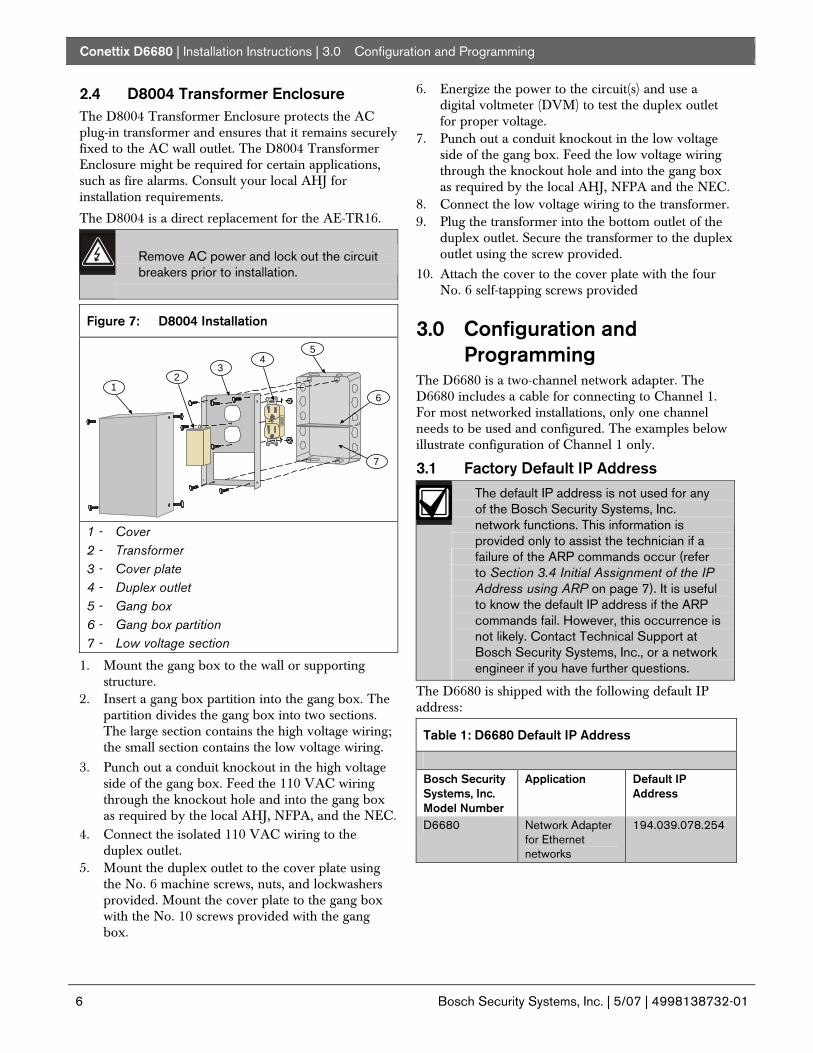
23. If you want to enable encryption, select 6 Security from the main menu and continue with Step 24.
If encryption is enabled on the D6680 (refer to Figure 13), you must enable it on all field devices (C900TTL-E, D9133TTL-E, DX4020) with the same key. Encryption must also be enabled in the D6600 Receiver. Refer to the D6600 Program Entry Guide (P/N: 4998122702).
The network interface module (D6680, C900TTL-E, D9133TTL-E, or DX4020) must have the proper software version to support encryption. For more details, refer to the Device Installer Operation and Installation Guide (P/N: 4998138688).
Figure 13: D6680 Encryption
24. At Disable SNMP (N) N, press [ENTER].
25. At SNMP Community Name ( ): press [ENTER].
26. At Disable Telnet Setup (N) N, press [ENTER].
27. At Disable Port 77Feh (N) N, press [ENTER].
28. At Disable Web Server (N) N, press [ENTER].
29. At Disable ECHO ports (Y) Y, press [ENTER].
30. At Enable Encryption (N), press [ENTER].
31. At Change keys (N), press ‘Y’. Enter keys as follows:
• These 16 bytes (32 characters) should match the bytes programmed in the D6680.
• Default value is 01-02-03-04-05-06-07-08-09-10-11-12-13-14-15-16.
Conettix D6680 | Installation Instructions | 3.0 Configuration and Programming
12 Bosch Security Systems, Inc. | 5/07 | 4998138732-01
32. At Enable Enhanced Password (N), press [ENTER].
After you make all the changes and verify them for accuracy, you must save the information.
33. Select 9 – save and exit. When the connection to
host is lost, press [ENTER] to continue.
3.5.2 Using Telnet with Windows NT, Windows 2000, or Windows XP
Although the screen captures are specific to Windows 2000, they are similar for Windows NT and XP.
To complete the IP address configuration of the D6680, launch a telnet session:
You must be logged into Windows with an administrator privilege level.
This example uses the IP address of 10.25.124.148 and the MAC Address of 00-20-4a-51-01-a7
1. Select Start � Run to open an MS-DOS window.
2. Type telnet and click OK.
A DOS window appears:
The colors are inverted here for clarity. The normal prompt window appears with white text on black.
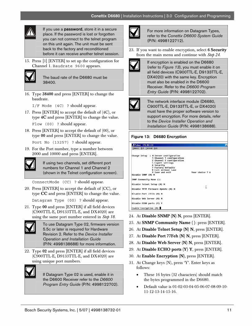
3. At the C:\> prompt, type telnet and press [ENTER].
4. At the Microsoft Telnet> prompt, type open
(space) IP Address (space) Port Number.
Figure 14: Command Prompt - telnet
Example: open 190.220.128.219 1
5. The connection fails the first time. This is normal.
Press [F3] to show the last line typed.
Backspace over the port value and change it to 9999.
Figure 15: Port Value Change
Example: open 190.220.128.219 9999
6. Press [ENTER].
7. Do Steps 8 through 32 in Section 3.5.1 Using Telnet with Windows 98SE or ME on page 8.
Configuration of the D6680 is complete. Perform this procedure again for any additional D6680s.
3.6 Programming Overview for the D6600
The D6600 Receiver is shipped with factory default program parameters and features already installed. Descriptions of the program items are found in the D6600 Program Entry Guide (P/N: 4998122702). Many of the operational features of the D6600 can be altered through programming options. The programming options you choose depend on:

Conettix D6680 | Installation Instructions | 3.0 Configuration and Programming
.
Bosch Security Systems, Inc. | 5/07 | 4998138732-01 13
• The type(s) of peripheral reporting device(s) used in your central station (for example external printer or automation computer)
• The supervision characteristics for these devices
• The type of communicators reporting to the receiver
• The number and type of receiving lines in use
3.7 Configuring for Network Communication Using a D6680
The following steps allow the D6600 to communicate with the host PC running the D6200 Programming Software using a D6680 on a network.
For the network communication to function, install a properly configured D6680. Refer to the previous sections. If network communications are not installed, further D6200 software programming using the network is not possible.
1. On the D6600 keypad, press [M/E] and enter the default passcode of [6][6][0][0] to enter the programming mode. Press [M/E] again.
To change any programming parameter, follow this syntax:
• Press [M/E], • Enter the desired value, • Press [M/E] again to store the value.
2. Scroll down to 6 NETWORK CONFIGURATION and press [M/E].
3. Scroll down to 6.1 COM4 Network Adapter
and press [M/E].
4. Verify that 6.1.1 COM4 Baud Rate is set to a
value of 9 and press [M/E].
5. Verify that 6.1.2 COM4 Data Bit is set to 8 (default) and press [M/E]. If necessary, change the value to 8
6. Verify that section 6.1.3 COM4 Parity is set
to 0 (default) and press [M/E]. If necessary, change the value to 0.
7. Verify that section 6.1.4 COM4 Stop Bit is set
to 1 (default) and press [M/E]. If necessary, change the value to 1.
8. Set 6.1.5 COM4 Network Adapter Enabled
to a value of 1 and press [M/E]. If the value is not 1, press [M/E][1][M/E].
9. If the D6680 connected to COM4 has encryption
enabled, Set 6.1.6 COM4 Network Encryption Enabled to 1.
If you did not install the optional D6672 Serial COM1 expansion kit, skip step 10.
10. If you installed COM1, press [CAN][▼]. Repeat steps 4 through step 9 for 6.2 COM1 Network Adapter.
11. Press [CAN] and scroll down to
6.3 Automation Network Connection.
12. Press [M/E] twice.

Conettix D6680 | Installation Instructions | 3.0 Configuration and Programming
14 Bosch Security Systems, Inc. | 5/07 | 4998138732-01
13. Scroll to 6.3.6 Network Automation Output Format.
14. Type 1 for 6500 mode or 2 for SIA mode and
press [M/E] to enter the selection.
15. Press [CAN] and scroll down to 6.3.7 Device.
16. Press [M/E].
17. Press 1 for automation communication through a
network, or 2 for automation communication through the RS-232 COM3 port.
18. Press [CAN] and scroll down to 6.4 D6200 Network Connections.
19. Press [M/E] to move to 6.4.1 IP Address 1.
20. Press [M/E] again to enter the IP address of the
host PC that runs the D6200 Software.
When entering an IP address through the keypad of the D6600, press an alpha character ([A] to [F]) to enter a decimal point in the IP address.
For example, enter IP address 202.96.168.127 as:
[2][0][2][A][9][6][A][1][6][8][A][1][2][7][M/E].
21. Scroll to 6.4.5 Network Programming Enable. Verify that the value is 1. If the value is not 1, press [M/E][1][M/E].
22. Set 6.2.6 COM1 Network Encryption
Enabled to 1 if the D6680 connected to COM1 has encryption enabled.
23. Press [CAN] repeatedly to return to the idle stage (time and date show on the LCD).
3.8 Editing Program Parameters Account database information must be entered into the D6600 before it is ready to manage and receive signals from alarm panels connected to a DX4020, D9133TTL-E, or C900TTL-E. Bosch recommends using the D6200 Programming Software to program this information.
The D6200 is a graphical use interface (GUI) that allows the user to perform the following functions:
• Retrieval of data files from the D6600 (CPU/Host/Network, Account Database, or Line Card)
• Editing of the D6600 data files (CPU/Host/Network, Account Database, or Line Card)
• Sending the files back to the D6600 (CPU/Host/Network, Account Database, or Line Card)
• Upgrading the Software installed in the D6600 (CPU, System, or PSTN line cards).
Refer to the D6200 Software Operation and Installation Guide (P/N: 4998154991) for information and procedures on how to accomplish these tasks.

Conettix D6680 | Installation Instructions | 4.0 Specifications
.
Bosch Security Systems, Inc. | 5/07 | 4998138732-01 15
4.0 Specifications Table 3: Specifications
Supported Protocols ARP, UDP, TCP, Telnet, ICMP, SNMP, DHCP, TFTP, HTTP, BootP and ECHO
Connectors
Serial: DB25: RS-232/RS-322/RS-485 serial port with DCE configuration DB9: RS232 serial port with DTE configuration
Network: 10BASE-T or 10BASE-FL LAN or WAN: RJ-45 Modular Jack (Ethernet)
Cables
Ethernet: Category 3 or better unshielded twisted pair Max Length: 328 ft. (100 m)
RS-232: Max Length: 50 ft. (15 m)
Data Rates Serial speed ranging from 300 bps to 115.2 kbps
Serial Line Formats
Characters 7 or 8 data bits
Stop bits: 1 or 2
Parity: Odd, even, none
Modem Controls RTS, CTS, DSR, DCD, DTR
Flow Control XON/XOFF CTS/RTS
Management HTTP (internal web server) SNMP (read only) Serial login Telnet login
System Software Flash ROM standard: downloadable from a TCP/IP host (TFTP) or over serial port
Diagnostic LEDs Network Transmit, Network Receive, Good Link, Collisions, Channel 1 Status, Channel 2 Status, Diagnostic
Compatibility Ethernet: v2.0/IEEE 802.3 D6600
Power Requirements 9 to 30 VDC or 9 to 25 VAC (External adapter included) Power Consumption: 3 W
AC Current Required UPS Standby Current: 35 mA
Power Input AC nominal operating range 120 or 240 VAC AC maximum operating range 100 to 240 VAC 50/60 Hz 0.2 A maximum
Standby Power An uninterrupted power supply (UPS) is required for use with the D6680, when used for UL FIRE Protective Signaling Systems. A 60 hr. minimum UPS standby power supply is required for UL Certification.
Environmental Operating Temperature: +41°F to +122°F (+5°C to +49°C)
Storage Temperature: -40°F to +151°F (+40°C to +66°C)
Dimensions (H x W x D):
Unit: 6.5 in. x 4.46 in. x 1.39 in. (16.5 cm x 11.3 cm x 36 mm)
Enclosure: 12.5 in. x 14.5 in. x 3 in. (31.8 cm x 36.8 cm x 76 mm) The enclosure is manufactured from 20 Gauge (1.0 mm), cold-rolled steel. A keyed lock is included.
Weight 1.1 lbs. (0.48 kg)

© 2007 Bosch Security Systems, Inc. 4998138732-01
Bosch Security Systems, Inc. 130 Perinton Parkway Fairport, NY 14450-9199 Customer Service: (800) 289-0096 Technical Support: (888) 886-6189


![depl EVOLUTION Series def - ScameOnLine [EN] - … OR/GOLD 8766 2 CLOSER GANG For wall round box 8750 0 GANG 8751 1 GANG 8752 2 GANG 8753 3 GANG 8765 2 GANG For universal sockets 50](https://img.pdfslide.us/doc/110x75/5c65ee5309d3f230488b5d48/depl-evolution-series-def-scameonline-en-orgold-8766-2-closer-gang-for-wall.jpg)