Embed Size (px)
Citation preview
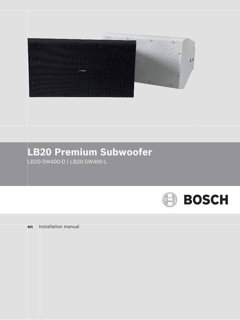
LB20 Premium SubwooferLB20-SW400-D | LB20-SW400-L
en Installation manual


Table of contents
1 Safety 41.1 Suspension 41.2 Notices 4
2 Short information 53 Introduction 63.1 System features 63.2 Packing list 73.3 Product information 8
4 Installation 94.1 Suspending the subwoofer 94.2 Replacing the logo 104.3 Installing the IP65 port covers 114.4 Installing the U-bracket - optional accessory 124.5 Installing the transformer input panel - optional accessory 134.6 Installing the crossover input panel - optional accessory 14
5 Wiring 155.1 Standard input panel 155.1.1 Mono operation 155.1.2 Stereo operation 165.2 Transformer input panel - optional accessory 175.2.1 Mono operation 175.2.2 Stereo operation 195.3 Crossover input panel - optional accessory 205.3.1 Mono operation 205.3.2 Stereo operation 21
6 Troubleshooting 237 Technical data 247.1 Dimensions 257.2 Frequency response and impedance 25
8 U-bracket dimensions - optional accessory 27
LB20 Premium Subwoofer Table of Contents | en 3
Bosch Security Systems B.V. Installation manual 2017.08 | 01 | F.01U.345.356
Safety
Suspension
!
Warning!
Suspending any object is potentially dangerous and should only be attempted by individuals
who have thorough knowledge of the techniques and regulations of suspending objects
overhead. Bosch strongly recommends all loudspeakers be suspended taking into account all
current national, federal, state, and local laws and regulations. It is the responsibility of the
installer to ensure all loudspeakers are safely installed in accordance with all such
requirements. When loudspeakers are suspended, Bosch strongly recommends the system be
inspected at least once per year or as laws and regulations require. If any sign of weakness or
damage is detected, remedial action should be taken immediately. The user is responsible for
making sure the wall, ceiling, or structure is capable of supporting all objects suspended
overhead. Any hardware used to suspend a loudspeaker not associated with Bosch is the
responsibility of others.
Safety pointAs an added safety measure, it is suggested the user install an extra suspension point back tothe building structural supports. This safety point should have as little slack as possible (lessthan 1-inch is preferable).
NoticesOld electrical and electronic appliancesElectrical or electronic devices that are no longer serviceable must be collected separately andsent for environmentally compatible recycling (in accordance with the European WasteElectrical and Electronic Equipment Directive).To dispose of old electrical or electronic devices, you should use the return and collectionsystems put in place in the country concerned.
Copyright and disclaimerAll rights reserved. No part of this document may be reproduced or transmitted in any form byany means, electronic, mechanical, photocopying, recording, or otherwise, without the priorwritten permission of the publisher. For information on getting permission for reprints andexcerpts, contact Bosch.The content and illustrations are subject to change without prior notice.
1
1.1
1.2
4 en | Safety LB20 Premium Subwoofer
2017.08 | 01 | F.01U.345.356 Installation manual Bosch Security Systems B.V.
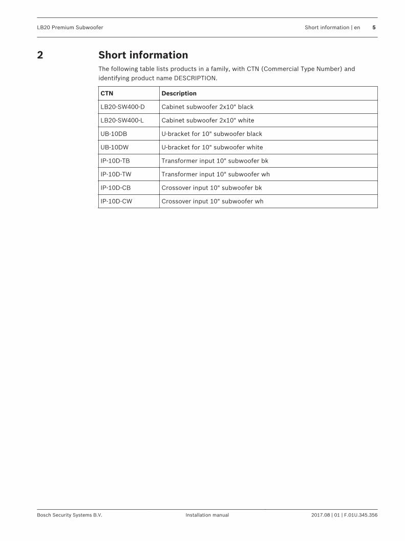
Short informationThe following table lists products in a family, with CTN (Commercial Type Number) andidentifying product name DESCRIPTION.
CTN Description
LB20-SW400-D Cabinet subwoofer 2x10" black
LB20-SW400-L Cabinet subwoofer 2x10" white
UB-10DB U-bracket for 10" subwoofer black
UB-10DW U-bracket for 10" subwoofer white
IP-10D-TB Transformer input 10" subwoofer bk
IP-10D-TW Transformer input 10" subwoofer wh
IP-10D-CB Crossover input 10" subwoofer bk
IP-10D-CW Crossover input 10" subwoofer wh
2
LB20 Premium Subwoofer Short information | en 5
Bosch Security Systems B.V. Installation manual 2017.08 | 01 | F.01U.345.356
IntroductionThe LB20-SW400 subwoofer, from Bosch, is a compact, high-performance, dual wooferloudspeaker with outstanding performance for the most demanding professional andcommercial sound applications. Designed and engineered for use in background andforeground music, and sound reinforcement applications, the LB20-SW400 subwoofer is theideal solution for indoor and outdoor applications, such as restaurants, bars, patios, retail,fitness clubs, hospitality, theme parks, leisure venues, and others. Ease of installation, andflexible options for mounting solutions and weather resistance, the LB20-SW400 subwoofer isthe perfect solution for a wide variety of surface mount applications. The LB20-SW400 subwoofer has been carefully engineered to resist outdoor environments,without compromising on performance for indoor applications. The subwoofer is IP54 rated,and its weather-proofing is complemented with exceptional cabinet and grille resistanceagainst sun, salt and moisture. For the toughest weather conditions, the IP rating of the LB20-SW400 subwoofer can be upgraded to IP65, using the included port plug accessory. Read through this manual to familiarize yourself with the safety information, features, andapplications before you use these products.
System features– Two 10 inch high-excursion woofers– Carefully engineered for outdoor environments (IP54 and IP65), without compromising
performance– 400 W power handling provides for 120 dB maximum SPL (126 dB peak)– 70/100 V transformer input panel accessory available– Crossover input panel accessory available
3
3.1
6 en | Introduction LB20 Premium Subwoofer
2017.08 | 01 | F.01U.345.356 Installation manual Bosch Security Systems B.V.
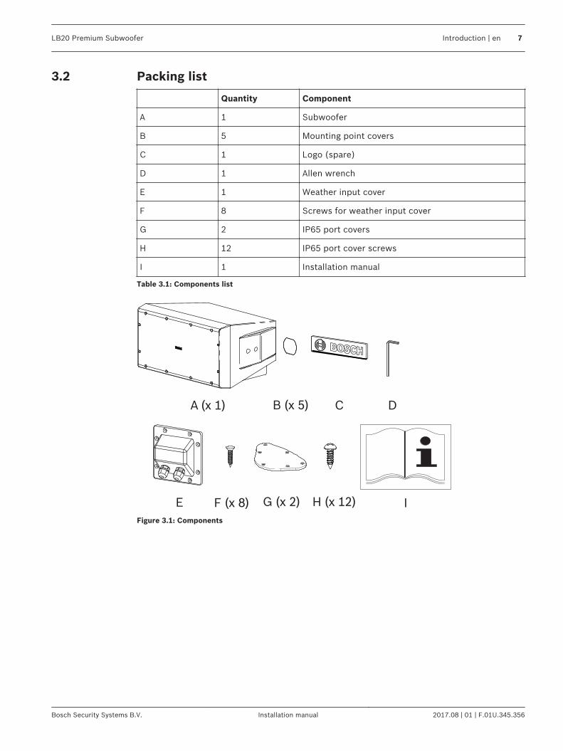
Packing list
Quantity Component
A 1 Subwoofer
B 5 Mounting point covers
C 1 Logo (spare)
D 1 Allen wrench
E 1 Weather input cover
F 8 Screws for weather input cover
G 2 IP65 port covers
H 12 IP65 port cover screws
I 1 Installation manual
Table 3.1: Components list
A (x 1) C
IE F (x 8) G (x 2) H (x 12)
DB (x 5)
Figure 3.1: Components
3.2
LB20 Premium Subwoofer Introduction | en 7
Bosch Security Systems B.V. Installation manual 2017.08 | 01 | F.01U.345.356
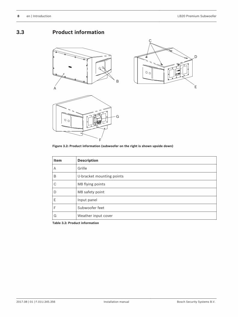
Product information
A
B
F
G
C
E
D
Figure 3.2: Product information (subwoofer on the right is shown upside down)
Item Description
A Grille
B U-bracket mounting points
C M8 flying points
D M8 safety point
E Input panel
F Subwoofer feet
G Weather input cover
Table 3.2: Product information
3.3
8 en | Introduction LB20 Premium Subwoofer
2017.08 | 01 | F.01U.345.356 Installation manual Bosch Security Systems B.V.
InstallationFor safety, ensure the mounting surface supports more than the weight of the speaker. Useonly industry-accepted fasteners and mounting methods when mounting the loudspeaker.Consult an expert if you are unsure.
!
Caution!
It is the installer's responsibility to determine and use the proper mounting hardware for
the wall construction type.
Disregarding this caution could result in damage to the product and personal injuries may
occur.
Safety pointAs an added safety measure, it is suggested the user install an extra suspension point back tothe building structural supports. This safety point should have as little slack as possible (lessthan 1-inch is preferable).
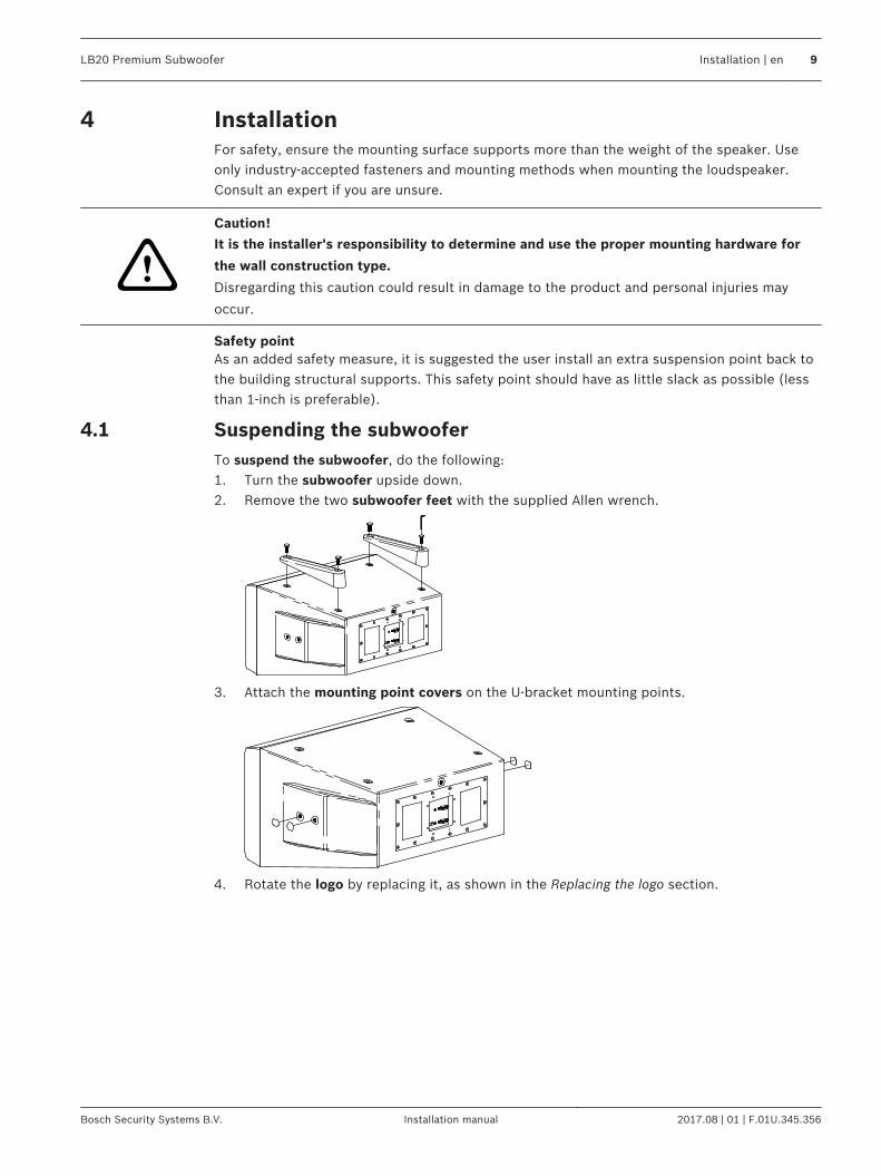
Suspending the subwooferTo suspend the subwoofer, do the following:1. Turn the subwoofer upside down.2. Remove the two subwoofer feet with the supplied Allen wrench.
3. Attach the mounting point covers on the U-bracket mounting points.
4. Rotate the logo by replacing it, as shown in the Replacing the logo section.
4
4.1
LB20 Premium Subwoofer Installation | en 9
Bosch Security Systems B.V. Installation manual 2017.08 | 01 | F.01U.345.356
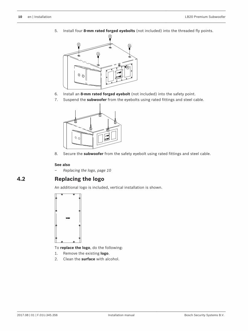
5. Install four 8-mm rated forged eyebolts (not included) into the threaded fly points.
6. Install an 8-mm rated forged eyebolt (not included) into the safety point.7. Suspend the subwoofer from the eyebolts using rated fittings and steel cable.
8. Secure the subwoofer from the safety eyebolt using rated fittings and steel cable.
See also– Replacing the logo, page 10
Replacing the logoAn additional logo is included, vertical installation is shown.
To replace the logo, do the following:1. Remove the existing logo.2. Clean the surface with alcohol.
4.2
10 en | Installation LB20 Premium Subwoofer
2017.08 | 01 | F.01U.345.356 Installation manual Bosch Security Systems B.V.
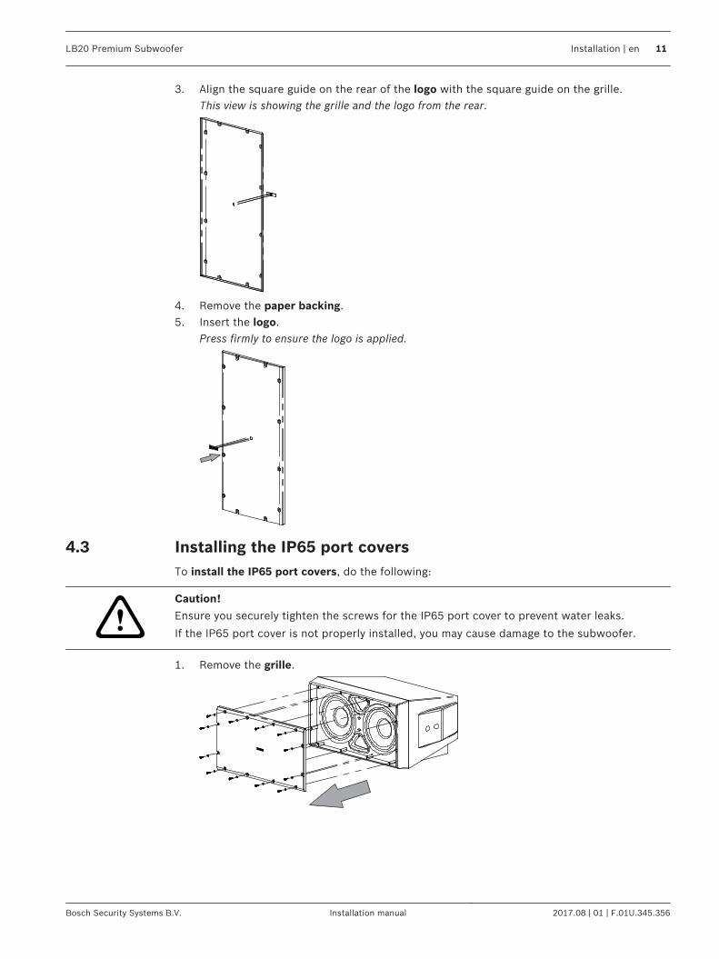
3. Align the square guide on the rear of the logo with the square guide on the grille.This view is showing the grille and the logo from the rear.
4. Remove the paper backing.5. Insert the logo.
Press firmly to ensure the logo is applied.
Installing the IP65 port coversTo install the IP65 port covers, do the following:
!
Caution!
Ensure you securely tighten the screws for the IP65 port cover to prevent water leaks.
If the IP65 port cover is not properly installed, you may cause damage to the subwoofer.
1. Remove the grille.
4.3
LB20 Premium Subwoofer Installation | en 11
Bosch Security Systems B.V. Installation manual 2017.08 | 01 | F.01U.345.356
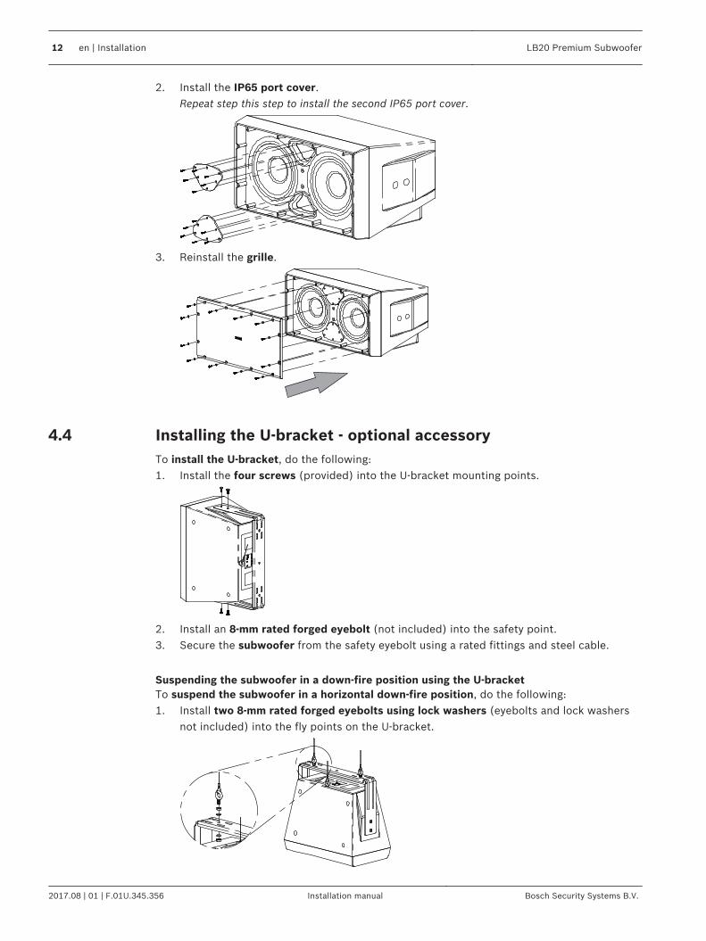
2. Install the IP65 port cover.Repeat step this step to install the second IP65 port cover.
3. Reinstall the grille.
Installing the U-bracket - optional accessoryTo install the U-bracket, do the following:1. Install the four screws (provided) into the U-bracket mounting points.
2. Install an 8-mm rated forged eyebolt (not included) into the safety point.3. Secure the subwoofer from the safety eyebolt using a rated fittings and steel cable.
Suspending the subwoofer in a down-fire position using the U-bracketTo suspend the subwoofer in a horizontal down-fire position, do the following:1. Install two 8-mm rated forged eyebolts using lock washers (eyebolts and lock washers
not included) into the fly points on the U-bracket.
4.4
12 en | Installation LB20 Premium Subwoofer
2017.08 | 01 | F.01U.345.356 Installation manual Bosch Security Systems B.V.
2. Install an 8-mm rated forged eyebolt (not included) into the safety point.3. Suspend the subwoofer from the eyebolts using rated fittings and steel cable.4. Secure the subwoofer from the safety eyebolt using a rated fittings and steel cable.
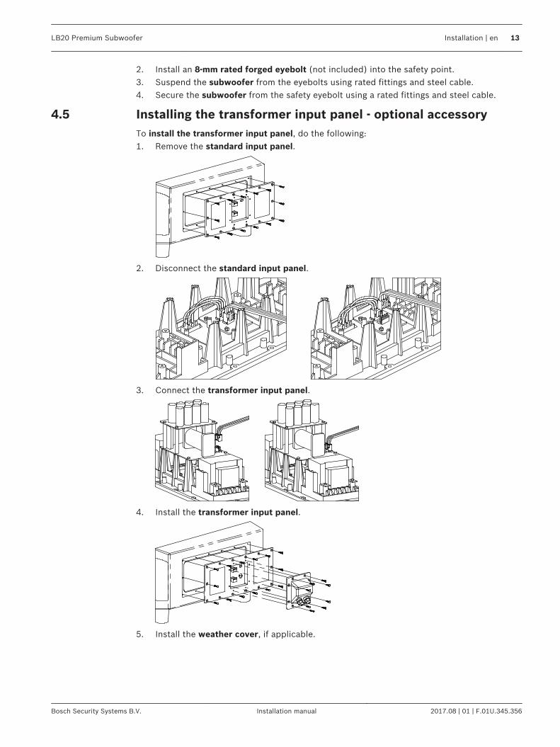
Installing the transformer input panel - optional accessoryTo install the transformer input panel, do the following:1. Remove the standard input panel.
2. Disconnect the standard input panel.
3. Connect the transformer input panel.
4. Install the transformer input panel.
5. Install the weather cover, if applicable.
4.5
LB20 Premium Subwoofer Installation | en 13
Bosch Security Systems B.V. Installation manual 2017.08 | 01 | F.01U.345.356
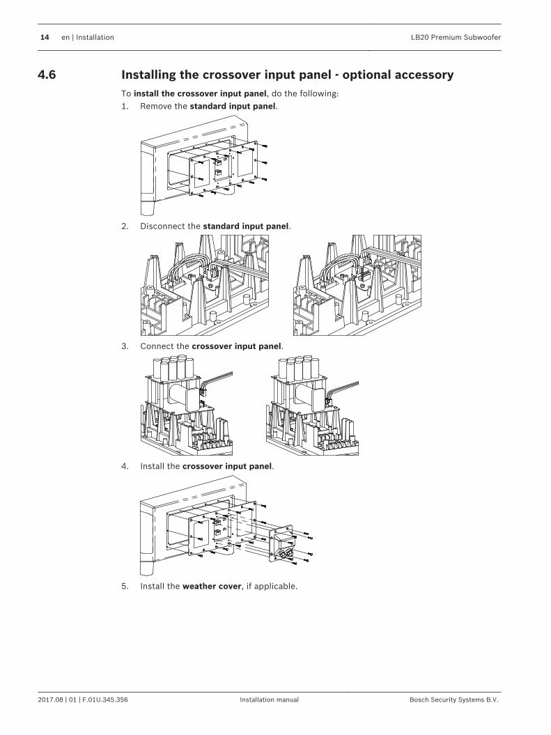
Installing the crossover input panel - optional accessoryTo install the crossover input panel, do the following:1. Remove the standard input panel.
2. Disconnect the standard input panel.
3. Connect the crossover input panel.
4. Install the crossover input panel.
5. Install the weather cover, if applicable.
4.6
14 en | Installation LB20 Premium Subwoofer
2017.08 | 01 | F.01U.345.356 Installation manual Bosch Security Systems B.V.
Wiring
Standard input panel
Mono operation
!
Caution!
For mono operation only use either the first two pins or the last two pins of the FR/IN
connector. Do not wire the amplifier to all four pins.
May cause damage to the amplifier if connected improperly.
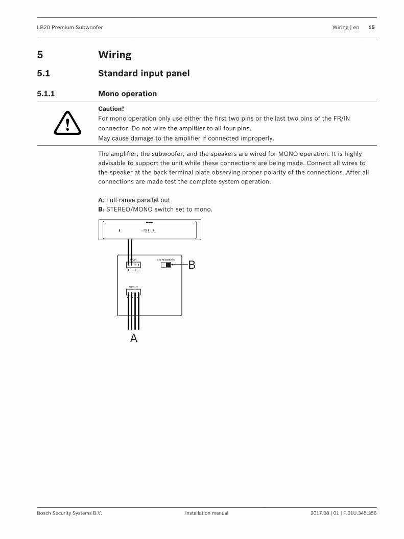
The amplifier, the subwoofer, and the speakers are wired for MONO operation. It is highlyadvisable to support the unit while these connections are being made. Connect all wires tothe speaker at the back terminal plate observing proper polarity of the connections. After allconnections are made test the complete system operation. A: Full-range parallel outB: STEREO/MONO switch set to mono.
Fault
Signal/Clip
CH1 CH2 CH3 CH4
A
B
5
5.1
5.1.1
LB20 Premium Subwoofer Wiring | en 15
Bosch Security Systems B.V. Installation manual 2017.08 | 01 | F.01U.345.356
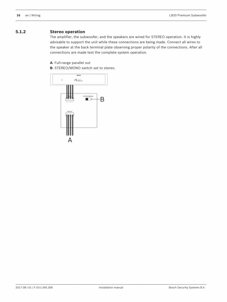
Stereo operationThe amplifier, the subwoofer, and the speakers are wired for STEREO operation. It is highlyadvisable to support the unit while these connections are being made. Connect all wires tothe speaker at the back terminal plate observing proper polarity of the connections. After allconnections are made test the complete system operation. A: Full-range parallel outB: STEREO/MONO switch set to stereo.
Fault
Signal/Clip
CH1 CH2 CH3 CH4
A
B
5.1.2
16 en | Wiring LB20 Premium Subwoofer
2017.08 | 01 | F.01U.345.356 Installation manual Bosch Security Systems B.V.
Transformer input panel - optional accessory
Mono operation
!
Caution!
For mono operation only use either the first two pins or the last two pins of the FR/IN
connector. Do not wire the amplifier to all four pins.
May cause damage to the amplifier if connected improperly.
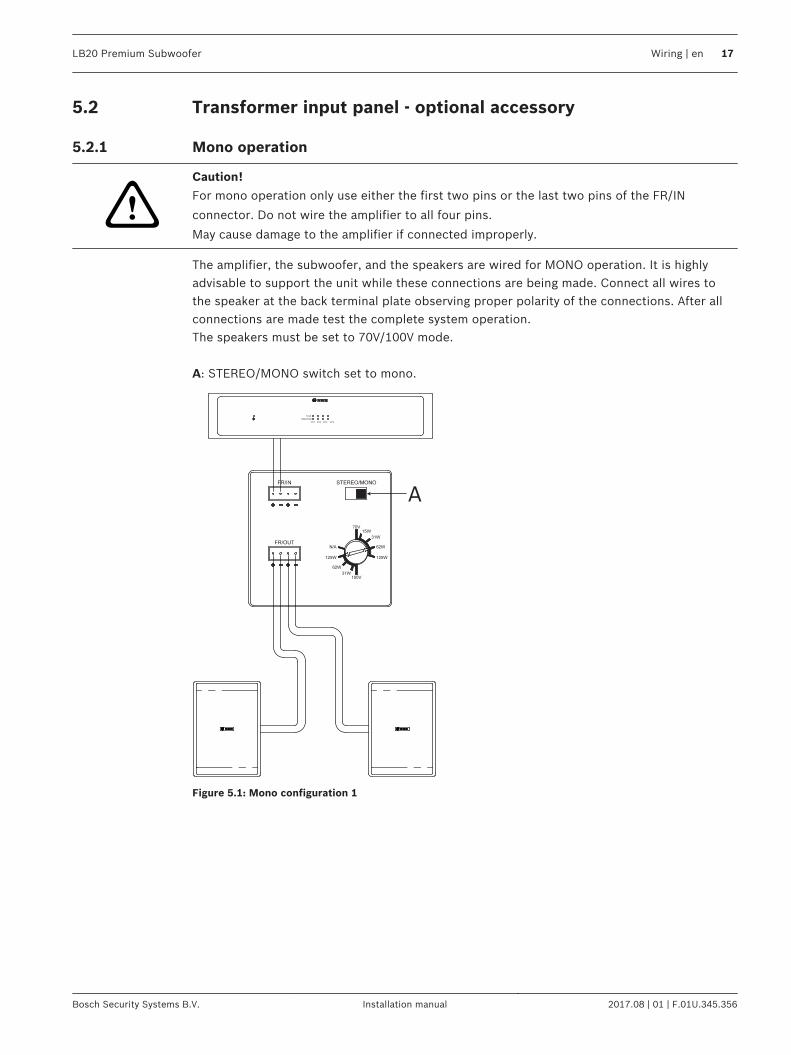
The amplifier, the subwoofer, and the speakers are wired for MONO operation. It is highlyadvisable to support the unit while these connections are being made. Connect all wires tothe speaker at the back terminal plate observing proper polarity of the connections. After allconnections are made test the complete system operation.The speakers must be set to 70V/100V mode. A: STEREO/MONO switch set to mono.
Fault
Signal/Clip
CH1 CH2 CH3 CH4
A
Figure 5.1: Mono configuration 1
5.2
5.2.1
LB20 Premium Subwoofer Wiring | en 17
Bosch Security Systems B.V. Installation manual 2017.08 | 01 | F.01U.345.356
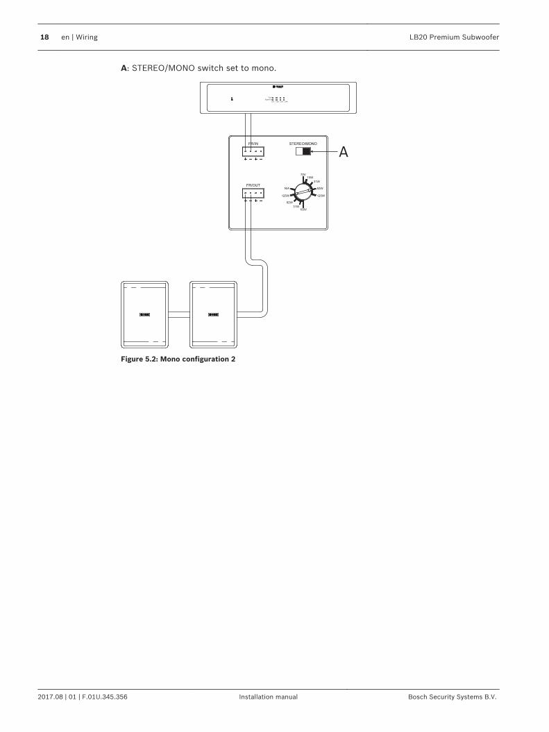
A: STEREO/MONO switch set to mono.
Fault
Signal/Clip
CH1 CH2 CH3 CH4
A
Figure 5.2: Mono configuration 2
18 en | Wiring LB20 Premium Subwoofer
2017.08 | 01 | F.01U.345.356 Installation manual Bosch Security Systems B.V.
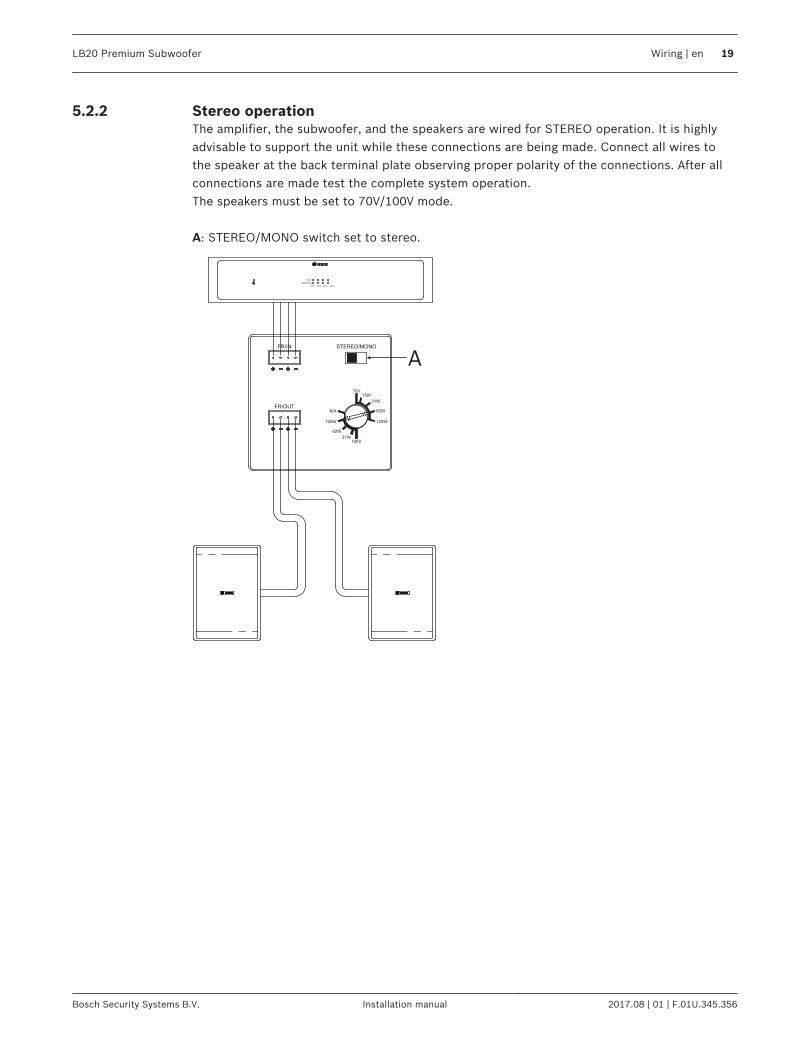
Stereo operationThe amplifier, the subwoofer, and the speakers are wired for STEREO operation. It is highlyadvisable to support the unit while these connections are being made. Connect all wires tothe speaker at the back terminal plate observing proper polarity of the connections. After allconnections are made test the complete system operation.The speakers must be set to 70V/100V mode. A: STEREO/MONO switch set to stereo.
Fault
Signal/Clip
CH1 CH2 CH3 CH4
A
5.2.2
LB20 Premium Subwoofer Wiring | en 19
Bosch Security Systems B.V. Installation manual 2017.08 | 01 | F.01U.345.356
Crossover input panel - optional accessory
Mono operation
!
Caution!
For mono operation only use either the first two pins or the last two pins of the FR/IN
connector. Do not wire the amplifier to all four pins.
May cause damage to the amplifier if connected improperly.
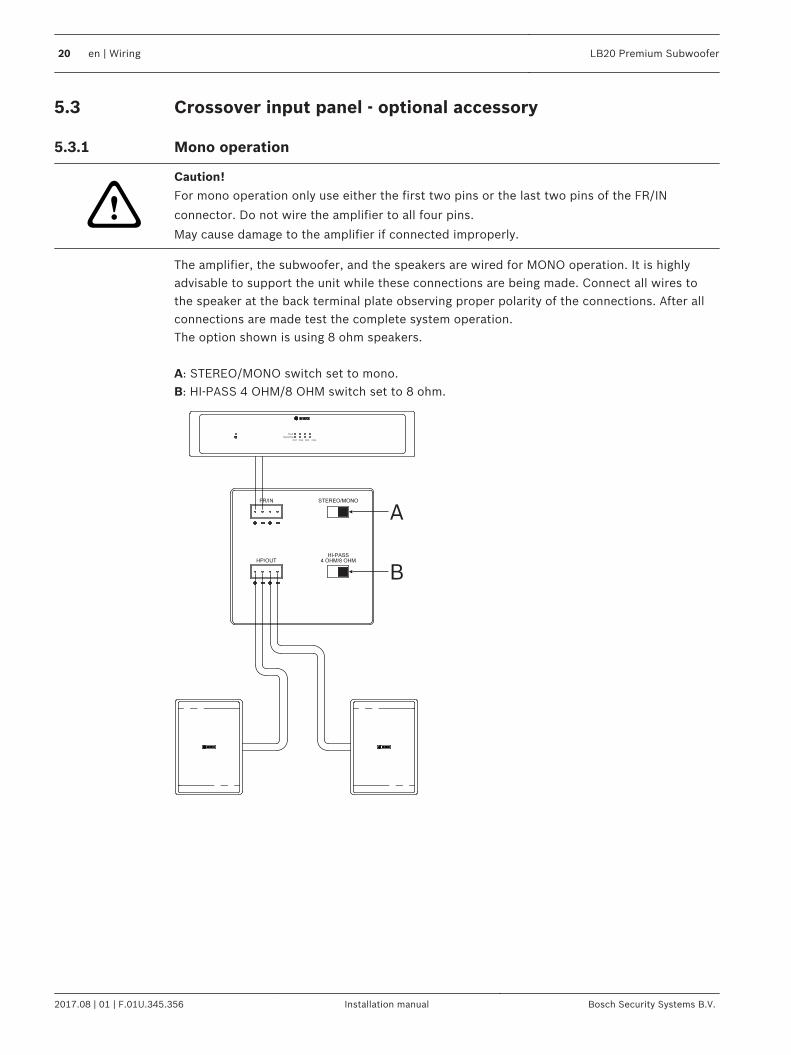
The amplifier, the subwoofer, and the speakers are wired for MONO operation. It is highlyadvisable to support the unit while these connections are being made. Connect all wires tothe speaker at the back terminal plate observing proper polarity of the connections. After allconnections are made test the complete system operation.The option shown is using 8 ohm speakers. A: STEREO/MONO switch set to mono.B: HI-PASS 4 OHM/8 OHM switch set to 8 ohm.
Fault
Signal/Clip
CH1 CH2 CH3 CH4
A
B
5.3
5.3.1
20 en | Wiring LB20 Premium Subwoofer
2017.08 | 01 | F.01U.345.356 Installation manual Bosch Security Systems B.V.
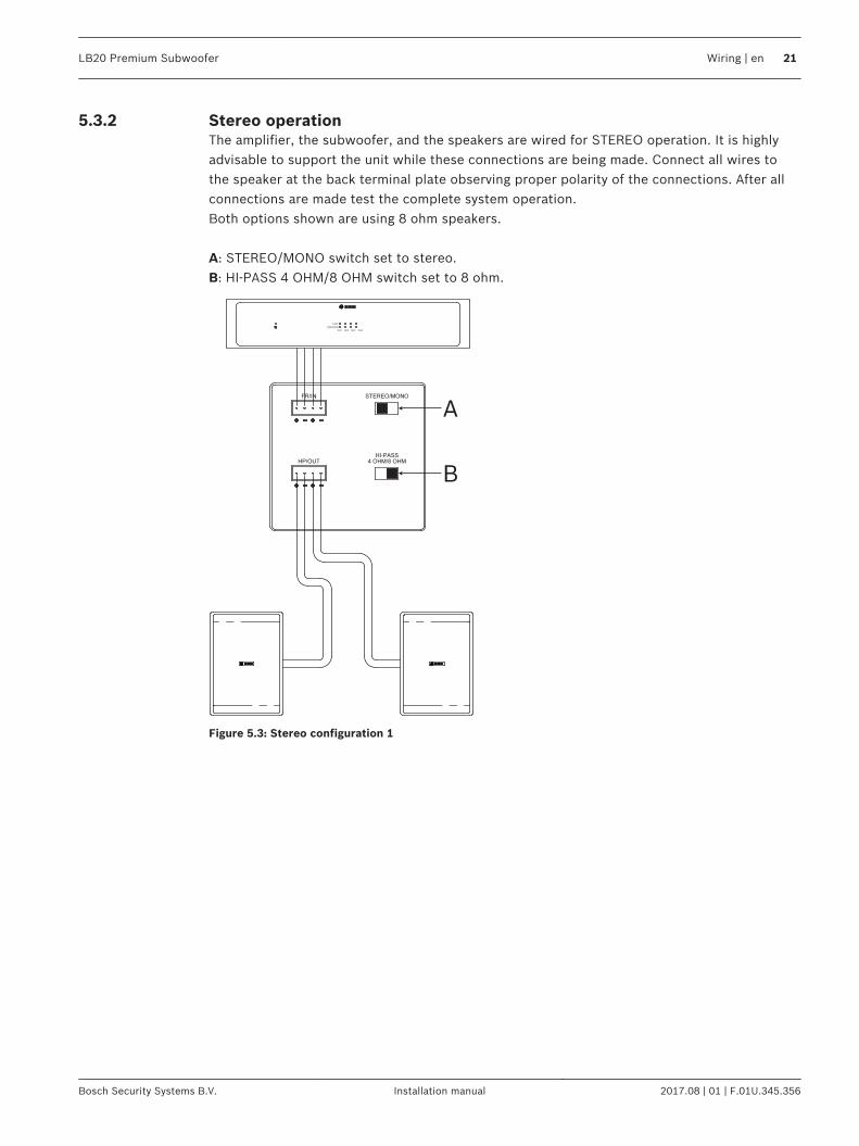
Stereo operationThe amplifier, the subwoofer, and the speakers are wired for STEREO operation. It is highlyadvisable to support the unit while these connections are being made. Connect all wires tothe speaker at the back terminal plate observing proper polarity of the connections. After allconnections are made test the complete system operation.Both options shown are using 8 ohm speakers. A: STEREO/MONO switch set to stereo.B: HI-PASS 4 OHM/8 OHM switch set to 8 ohm.
Fault
Signal/Clip
CH1 CH2 CH3 CH4
A
B
Figure 5.3: Stereo configuration 1
5.3.2
LB20 Premium Subwoofer Wiring | en 21
Bosch Security Systems B.V. Installation manual 2017.08 | 01 | F.01U.345.356
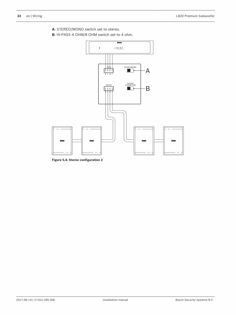
A: STEREO/MONO switch set to stereo.B: HI-PASS 4 OHM/8 OHM switch set to 4 ohm.
Fault
Signal/Clip
CH1 CH2 CH3 CH4
A
B
Figure 5.4: Stereo configuration 2
22 en | Wiring LB20 Premium Subwoofer
2017.08 | 01 | F.01U.345.356 Installation manual Bosch Security Systems B.V.
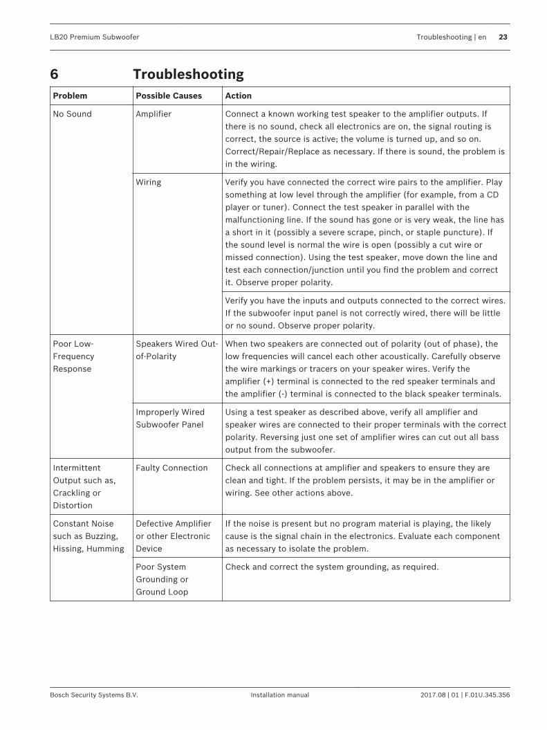
TroubleshootingProblem Possible Causes Action
No Sound Amplifier Connect a known working test speaker to the amplifier outputs. Ifthere is no sound, check all electronics are on, the signal routing iscorrect, the source is active; the volume is turned up, and so on.Correct/Repair/Replace as necessary. If there is sound, the problem isin the wiring.
Wiring Verify you have connected the correct wire pairs to the amplifier. Playsomething at low level through the amplifier (for example, from a CDplayer or tuner). Connect the test speaker in parallel with themalfunctioning line. If the sound has gone or is very weak, the line hasa short in it (possibly a severe scrape, pinch, or staple puncture). Ifthe sound level is normal the wire is open (possibly a cut wire ormissed connection). Using the test speaker, move down the line andtest each connection/junction until you find the problem and correctit. Observe proper polarity.
Verify you have the inputs and outputs connected to the correct wires.If the subwoofer input panel is not correctly wired, there will be littleor no sound. Observe proper polarity.
Poor Low-FrequencyResponse
Speakers Wired Out-of-Polarity
When two speakers are connected out of polarity (out of phase), thelow frequencies will cancel each other acoustically. Carefully observethe wire markings or tracers on your speaker wires. Verify theamplifier (+) terminal is connected to the red speaker terminals andthe amplifier (-) terminal is connected to the black speaker terminals.
Improperly WiredSubwoofer Panel
Using a test speaker as described above, verify all amplifier andspeaker wires are connected to their proper terminals with the correctpolarity. Reversing just one set of amplifier wires can cut out all bassoutput from the subwoofer.
IntermittentOutput such as,Crackling orDistortion
Faulty Connection Check all connections at amplifier and speakers to ensure they areclean and tight. If the problem persists, it may be in the amplifier orwiring. See other actions above.
Constant Noisesuch as Buzzing,Hissing, Humming
Defective Amplifieror other ElectronicDevice
If the noise is present but no program material is playing, the likelycause is the signal chain in the electronics. Evaluate each componentas necessary to isolate the problem.
Poor SystemGrounding orGround Loop
Check and correct the system grounding, as required.
6
LB20 Premium Subwoofer Troubleshooting | en 23
Bosch Security Systems B.V. Installation manual 2017.08 | 01 | F.01U.345.356
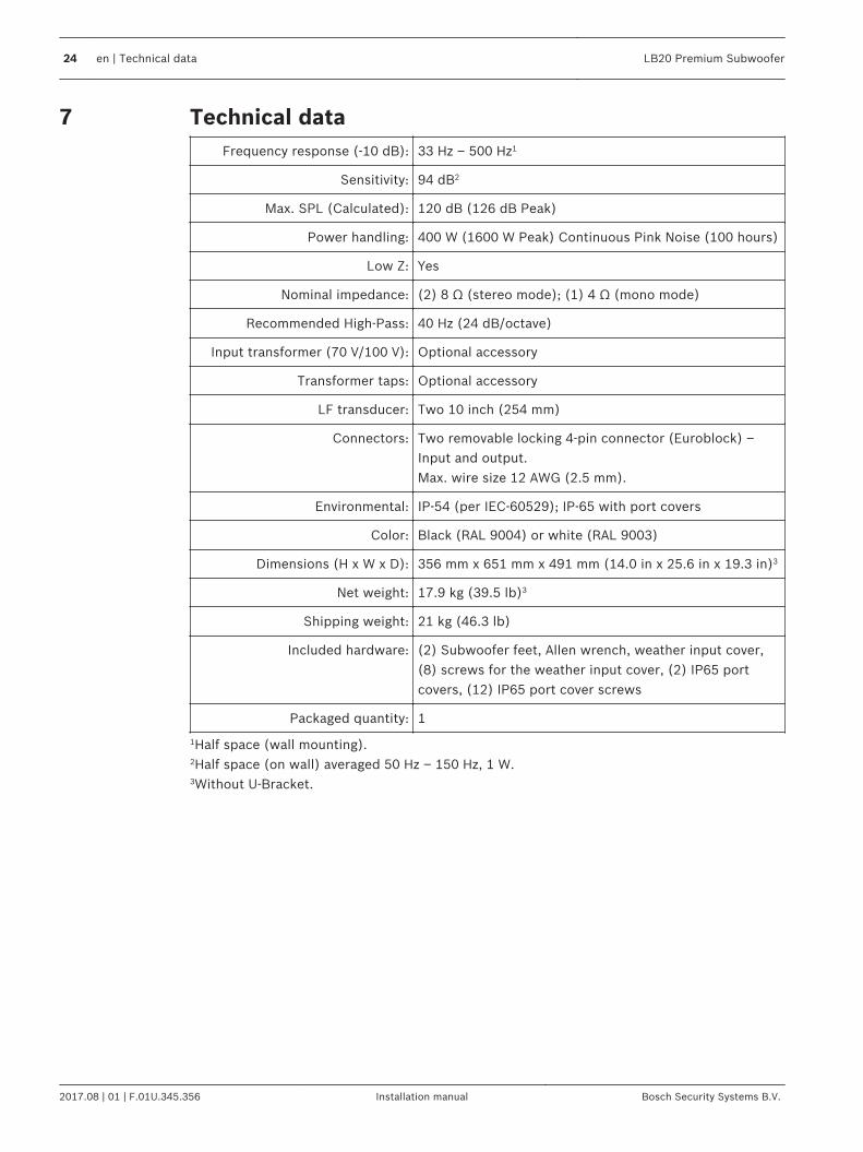
Technical dataFrequency response (-10 dB): 33 Hz – 500 Hz1
Sensitivity: 94 dB2
Max. SPL (Calculated): 120 dB (126 dB Peak)
Power handling: 400 W (1600 W Peak) Continuous Pink Noise (100 hours)
Low Z: Yes
Nominal impedance: (2) 8 Ω (stereo mode); (1) 4 Ω (mono mode)
Recommended High-Pass: 40 Hz (24 dB/octave)
Input transformer (70 V/100 V): Optional accessory
Transformer taps: Optional accessory
LF transducer: Two 10 inch (254 mm)
Connectors: Two removable locking 4-pin connector (Euroblock) –Input and output. Max. wire size 12 AWG (2.5 mm).
Environmental: IP-54 (per IEC-60529); IP-65 with port covers
Color: Black (RAL 9004) or white (RAL 9003)
Dimensions (H x W x D): 356 mm x 651 mm x 491 mm (14.0 in x 25.6 in x 19.3 in)3
Net weight: 17.9 kg (39.5 lb)3
Shipping weight: 21 kg (46.3 lb)
Included hardware: (2) Subwoofer feet, Allen wrench, weather input cover,(8) screws for the weather input cover, (2) IP65 portcovers, (12) IP65 port cover screws
Packaged quantity: 1
1Half space (wall mounting).2Half space (on wall) averaged 50 Hz – 150 Hz, 1 W.3Without U-Bracket.
7
24 en | Technical data LB20 Premium Subwoofer
2017.08 | 01 | F.01U.345.356 Installation manual Bosch Security Systems B.V.
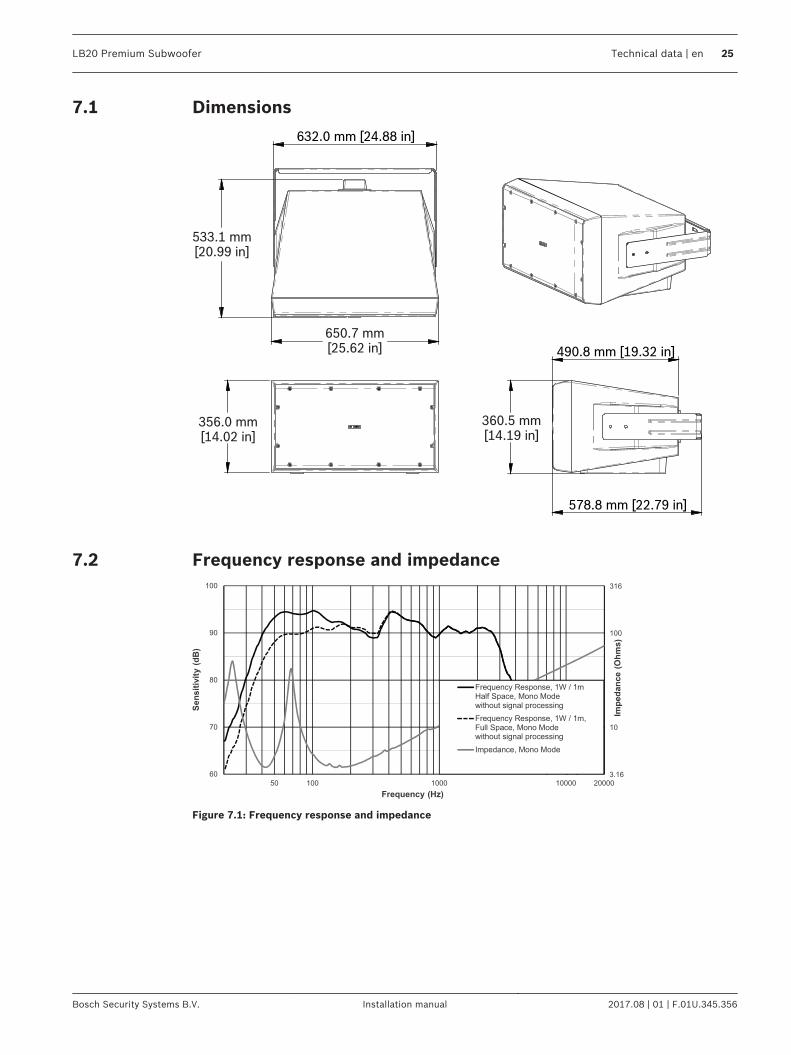
Dimensions
632.0 mm [24.88 in]
533.1 mm[20.99 in]
650.7 mm[25.62 in]
356.0 mm[14.02 in]
360.5 mm[14.19 in]
578.8 mm [22.79 in]
490.8 mm [19.32 in]
Frequency response and impedance
Figure 7.1: Frequency response and impedance
7.1
7.2
LB20 Premium Subwoofer Technical data | en 25
Bosch Security Systems B.V. Installation manual 2017.08 | 01 | F.01U.345.356
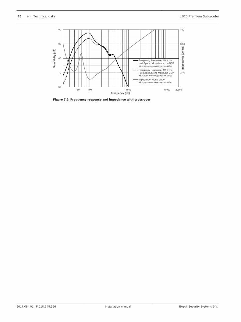
Figure 7.2: Frequency response and impedance with cross-over
26 en | Technical data LB20 Premium Subwoofer
2017.08 | 01 | F.01U.345.356 Installation manual Bosch Security Systems B.V.
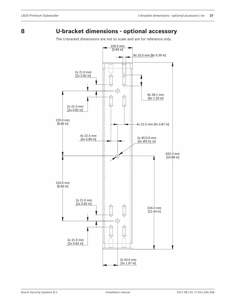
U-bracket dimensions - optional accessoryThe U-bracket dimensions are not to scale and are for reference only.
100.0 mm[3.94 in]
8x 10.0 mm [8x 0.39 in]
8x 38.1 mm[8x 1.50 in]
2x 21.0 mm[2x 0.82 in]
2x 21.0 mm[2x 0.82 in]
4x 22.5 mm [4x 0.87 in]
4x 22.5 mm[4x 0.89 in] 3x 13.0 mm∅
[3x 0.51 in]∅
632.0 mm[24.88 in]
220.0 mm[8.66 in]
220.0 mm[8.66 in]
2x 21.0 mm[2x 0.82 in]
316.0 mm[12.44 in]
2x 21.0 mm[2x 0.82 in]
3x 50.0 mm[3x 1.97 in]
8
LB20 Premium Subwoofer U-bracket dimensions - optional accessory | en 27
Bosch Security Systems B.V. Installation manual 2017.08 | 01 | F.01U.345.356

Bosch Security Systems B.V.Torenallee 495617 BA EindhovenNetherlandswww.boschsecurity.com© Bosch Security Systems B.V., 2017