Embed Size (px)
Citation preview
Instruction Manual
EN Outdoor HousingSystems
Pressurized Dome
Pressurized Dome | Instruction Manual | Important Safeguards EN | 2
Bosch Security Systems | August 3, 2005
Important Safeguards
1. Read, Follow, and Retain Instructions - All safetyand operating instructions should be read andfollowed before operating the unit. Retain instructionsfor future reference.
2. Heed Warnings - Adhere to all warnings on the unitand in the operating instructions.
3. Attachments - Attachments not recommended bythe product manufacturer should not be used, as theymay cause hazards.
4. Installation Cautions - Do not place this unit on anunstable stand, tripod, bracket, or mount. The unitmay fall, causing serious injury to a person andserious damage to the unit. Use only manufacturer-recommended accessories, or those sold with theproduct. Mount the unit per the manufacturer'sinstructions. Appliance and cart combination shouldbe moved with care. Quick stops, excessive force, oruneven surfaces may cause the appliance and cartcombination to overturn.
5. Cleaning - Unplug the unit from the outlet beforecleaning. Follow any instructions provided with theunit. Generally, using a damp cloth for cleaning issufficient. Do not use liquid cleaners or aerosolcleaners.
6. Servicing - Do not attempt to service this unityourself. Opening or removing covers may exposeyou to dangerous voltage or other hazards. Refer allservicing to qualified service personnel.
7. Damage Requiring Service - Unplug the unit fromthe main AC power source and refer servicing toqualified service personnel under the followingconditions:• When the power supply cord or plug is damaged.• If liquid has been spilled or an object has fallen
into the unit.• If the unit has been exposed to water and/or
inclement weather (rain, snow, etc.).• If the unit does not operate normally, when
following the operating instructions. Adjust onlythose controls specified in the operatinginstructions. Improper adjustment of other controlsmay result in damage, and require extensive workby a qualified technician to restore the unit tonormal operation.
• If the unit has been dropped or the cabinetdamaged.
• If the unit exhibits a distinct change inperformance, this indicates that service is needed.
8. Replacement Parts - When replacement parts arerequired, the service technician should usereplacement parts specified by the manufacturer orthat have the same characteristics as the original part.Unauthorized substitutions may result in fire,electrical shock or other hazards.
9. Safety Check - Upon completion of servicing orrepairs to the unit, ask the service technician toperform safety checks to ensure proper operatingcondition.
10. Power Sources - Operate the unit only from the typeof power source indicated on the label. If unsure ofthe type of power supply to use, contact your dealeror local power company. • For units intended to operate from battery power,
refer to the operating instructions. • For units intended to operate with External Power
Supplies, use only the recommended approvedpower supplies.
• For units intended to operate with a limited powersource, this power source must comply withEN60950. Substitutions may damage the unit orcause fire or shock.
• For units intended to operate at 24VAC, normalinput voltage is 24VAC. Voltage applied to theunit's power input should not exceed 30VAC. User-supplied wiring, from the 24VAC supply tounit, must be in compliance with electrical codes(Class 2 power levels). Do not ground the 24VACsupply at the terminals or at the unit's powersupply terminals.
11. Coax Grounding - If an outside cable system isconnected to the unit, ensure that the cable system isgrounded. U.S.A. models only - Section 810 of theNational Electrical Code, ANSI/NFPA No.70,provides information regarding proper grounding ofthe mount and supporting structure, grounding of thecoax to a discharge unit, size of groundingconductors, location of discharge unit, connection togrounding electrodes, and requirements for thegrounding electrode.
12. Grounding or Polarization - This unit may beequipped with a polarized alternating current lineplug (a plug with one blade wider than the other).This safety feature allows the plug to fit into thepower outlet in only one way. If unable to insert theplug fully into the outlet, try reversing the plug. If theplug still fails to fit, contact an electrician to arrangereplacement of the obsolete outlet. Do not defeat thesafety purpose of the polarized plug.Alternately, this unit may be equipped with a 3-wire grounding plug (a plug with a third pin, forgrounding). This safety feature allows the plug to fitinto a grounding power outlet only. If unable to insertthe plug into the outlet, contact an electrician toarrange replacement of the obsolete outlet. Do notdefeat the safety purpose of the grounding plug.
13. Lightning - For added protection during a lightningstorm, or when this unit is left unattended andunused for long periods of time, unplug the unit fromthe wall outlet and disconnect the cable system. Thiswill prevent damage to the unit due to lightning andpower line surges.
Pressurized Dome | Instruction Manual | Safety Precautions EN | 3
Bosch Security Systems | August 3, 2005
Safety Precautions
Installation should be performed by qualifiedservice personnel only in accordance with theNational Electrical Code or applicable localcodes.
Power Disconnect. Units with or without ON-OFF switches have power supplied to theunit whenever the power cord is inserted into thepower source; however, the unit is operationalonly when the ON-OFF switch is in the ONposition. The power cord is the main powerdisconnect for all units.
CAUTION: TO REDUCE THE RISK OFELECTRIC SHOCK, DO NOT REMOVE COVER(OR BACK). NO USER SERVICEABLE PARTSINSIDE. REFER SERVICING TO QUALIFIEDSERVICE PERSONNEL.
This symbol indicates the presence ofuninsulated “dangerous voltage” within theproduct’s enclosure that can cause an electricshock.
This symbol indicates the presence ofimportant operating and maintenance(servicing) instructions in the literatureaccompanying the appliance.
For Indoor Product1. Water and Moisture - Do not use this unit near
water - for example, in a wet basement, in anunprotected outdoor installation or in any areaclassified as a wet location.
2. Object and Liquid Entry - Never push objects ofany kind into this unit through openings, as theymight touch dangerous voltage points or createshort circuits, resulting in a fire or electricalshock. Never spill liquid of any kind on the unit.
3. Power Cord and Power Cord Protection - Forunits intended to operate with 230VAC, 50Hz,the input and output power cord must complywith the latest versions of IEC Publication 227 orIEC Publication 245. Power supply cords should be routed so they arenot likely to be walked on or pinched. Payparticular attention to location of cords and plugs,convenience receptacles, and the point of exitfrom the appliance.
4. Overloading - Do not overload outlets andextension cords; this can result in a risk of fire orelectrical shock.
For Outdoor ProductPower Lines - An outdoor system should not belocated in the vicinity of overhead power lines,electric lights or power circuits, or where it maycontact such power lines or circuits. Wheninstalling an outdoor system, extreme care shouldbe taken to keep from touching power lines orcircuits, as this contact might be fatal. U.S.A.models only - refer to the National ElectricalCode Article 820 regarding installation of CATVsystems.
For Rack-mount Product1. Ventilation - Do not place this equipment in a
built-in installation or rack, unless properventilation is provided, or the manufacturer'sinstructions were followed. The equipment mustnot exceed its maximum operating temperaturerequirements.
2. Mechanical Loading - When rack-mounting theequipment, ensure that a hazardous condition isnot created by uneven mechanical loading.
24VAC UnitsDo not exceed 30VAC input. Voltage applied to the unit'spower input should not exceed 30VAC. Normal input voltage is 24VAC. User supplied wiring from 24VAC supply to unit must be in compliance with electrical codes(Class 2 power levels). Do not ground 24VAC supply atpower supply terminals or at unit's power supply terminals.
This equipment is to be isolated from the mains supply by a limited power source as specified inEN60950.
220-240V, 50Hz Power Cords220-240V, 50Hz power cords, input and output, must complywith the latest versions of IEC Publication 227 or IEC Publication 245.
Cover RemovalWARNING: Removal of the cover should only be performed by qualified service personnel - not user serviceable. The unit should always be unplugged beforeremoving the cover and remain unplugged while thecover is removed.
Pressurized Dome | Instruction Manual | FCC & ICES Information EN | 4
Bosch Security Systems | August 3, 2005
FCC & ICES INFORMATION(U.S.A. and Canadian Models Only)This device complies with part 15 of the FCC Rules. Operation issubject to the following two conditions:
(1) This device may not cause harmful interference, and(2) This device must accept any interference received,
including interference that may cause undesiredoperation.
NOTE: This equipment has been tested and found to complywith the limits for a Class A digital device, pursuant to Part 15 ofthe FCC Rules and ICES-003 of Industry Canada. These limitsare designed to provide reasonable protection against harmfulinterference when the equipment is operated in a commercial environment. This equipment generates, uses and radiates radiofrequency energy, and if not installed and used in accordancewith the instruction manual, may cause harmful interference toradio communications. Operation of this equipment in aresidential area is likely to cause harmful interference, in whichcase the user will be required to correct the interference at hisexpense.Intentional or unintentional changes or modifications, notexpressly approved by the party responsible for compliance, shallnot be made. Any such changes or modifications could void theuser’s authority to operate the equipment. If necessary, the usershould consult the dealer or an experienced radio/televisiontechnician for corrective action. The user may find the followingbooklet, prepared by the Federal Communications Commission,helpful: How to Identify and Resolve Radio-TV InterferenceProblems. This booklet is available from the U.S. GovernmentPrinting Office, Washington, DC 20402, Stock No. 004-000-00345-4.
WARNING: This is a Class A product. In a domesticenvironment, this product may cause radio interference,in which case, the user may be required to take adequatemeasures.
Sécurité
Attention : l'installation doit exclusivement être réalisée par dupersonnel qualifié, conformément au code national d'électricitéaméricain (NEC) ou au code d'électricité local en vigueur.
Coupure de l'alimentation. Qu'ils soient pourvus ou non d'uncommutateur ON/OFF, tous les appareils reçoivent de l'énergie unefois le cordon branché sur la source d'alimentation. Toutefois,l'appareil ne fonctionne réellement que lorsque le commutateur est réglé sur ON. Le débranchement du cordond'alimentation permet de couper l'alimentation des appareils.
ATTENTION : POUR ÉVITER TOUT RISQUE D'ÉLECTROCUTION,
N'ESSAYEZ PAS DE RETIRER LE CAPOT (OU LE PANNEAU
ARRIÈRE). CET APPAREIL NE CONTIENT AUCUN COMPOSANT
SUSCEPTIBLE D'ÊTRE RÉPARÉ PAR L'UTILISATEUR. CONFIEZ
LA RÉPARATION DE L'APPAREIL À DU PERSONNEL QUALIFIÉ.
Ce symbole signale que le produit renferme une « tensionpotentiellement dangereuse » non isolée susceptible deprovoquer une électrocution.
Ce symbole invite l'utilisateur à consulter les instructionsd'utilisation et d'entretien (dépannage) reprises dans ladocumentation qui accompagne l'appareil.
Sicherheitshinweise
Achtung! Die Installation sollte nur von qualifiziertemKundendienstpersonal gemäß jeweils zutreffenderElektrovorschriften ausgeführt werden.
Unterbrechung des Netzanschlusses. Geräte mit oder ohneNetzschalter haben Spannung am Gerät anliegen, sobald derNetzstecker in die Steckdose gesteckt wird. Das Gerät ist jedochnur betriebsbereit, wenn der Netzschalter (EIN/AUS) auf EINsteht. Wenn das Netzkabel aus der Steckdose gezogen wird, istdie Spannungszuführung zum Gerät vollkommen unterbrochen.
VORSICHT: UM EINEN ELEKTRISCHEN SCHLAG ZU
VERMEIDEN, IST DIE ABDECKUNG (ODER RÜCKSEITE) NICHT
ZU ENTFERNEN. ES BEFINDEN SICH KEINE TEILE IN DIESEM
BEREICH, DIE VOM BENUTZER GEWARTET WERDEN
KÖNNEN. LASSEN SIE WARTUNGSARBEITEN NUR VON
QUALIFIZIERTEM WARTUNGSPERSONAL AUSFÜHREN.
Das Symbol macht auf nicht isolierte „gefährliche Spannung"im Gehäuse aufmerksam. Dies kann zu einem elektrischenSchlag führen.
Der Benutzer sollte sich ausführlich über Anweisungen fürdie Bedienung und Instandhaltung (Wartung) in denbegleitenden Unterlagen informieren.
Precauciones de Seguridad
Atención: la instalación la debe realizar únicamente personalcualificado de conformidad con el National Electric Code o lasnormas aplicables en su país.
Desconexión de la alimentación. Las unidades con o sininterruptores de encendido/apagado reciben alimentacióneléctrica siempre que el cable de alimentación esté conectado ala fuente de alimentación. Sin embargo, la unidad sólo funcionacuando el interruptor está en la posición de encendido. El cablede alimentación es la principal fuente de desconexión de todaslas unidades.
PRECAUCIÓN: PARA DISMINUIR EL RIESGO DE DESCARGAELÉCTRICA, NO RETIRE LA CUBIERTA (NI LA PARTEPOSTERIOR). NO EXISTEN PIEZAS DE RECAMBIO EN ELINTERIOR DEL EQUIPO. EL PERSONAL DE SERVICIOCUALIFICADO SE ENCARGA DE REALIZAR LASREPARACIONES.
Este símbolo indica que existen puntos de tensión peligrosossin aislamiento dentro de la cubierta de la unidad. Estospuntos pueden constituir un riesgo de descarga eléctrica.
El usuario debe consultar las instrucciones de funcionamiento ymantenimiento (reparación) en la documentación que sesuministra con el aparato.
EN | 5Pressurized Dome | Instruction Manual | Safety Precautions
Bosch Security Systems | August 3, 2005
Veiligheidsmaatregelen
Attentie: het apparaat mag alleen door gekwalificeerd personeelworden geïnstalleerd. De installatie dient in overeenstemmingmet de nationale elektrische richtlijnen of de van toepassingzijnde lokale richtlijnen te worden uitgevoerd.
Spanning uitschakelen. Apparatuur met of zonder aan-uitschakelaar staat onder spanning zolang de stekker isaangesloten op de wandcontactdoos. De apparatuur is uitsluitendin werking als de aan-uitschakelaar aan staat. Het netsnoer is de"hoofdschakelaar" voor alle apparatuur.
VOORZICHTIG: OPEN DE BEHUIZING OF DE ACHTERKANTVAN HET APPARAAT NIET. ZO VERMINDERT U HET RISICOOP ELEKTRISCHE SCHOKKEN. IN HET APPARAATBEVINDEN ZICH GEEN ONDERDELEN DIE U ZELF KUNTREPAREREN. LAAT SERVICE EN ONDERHOUD UITVOERENDOOR GEKWALIFICEERD PERSONEEL.
Dit symbool geeft aan dat er binnen in het apparaatongeïsoleerde, gevaarlijke spanning aanwezig is die mogelijkelektrische schokken kan veroorzaken.
De gebruiker dient de bedienings- en onderhoudsvoorschriftente raadplegen in de documentatie die werd meegeleverd methet apparaat.
Sicurezza
Attenzione: l'installazione deve essere effettuata esclusivamenteda personale tecnico qualificato in conformità con il NationalElectrical Code o con le normative locali vigenti.
Scollegamento dell'alimentazione. Le unità dotate o sprovviste diinterruttori ON-OFF vengono alimentate quando si inserisce ilcavo nella presa dell'alimentazione. L'unità è tuttavia in funzionesolo quando l'interruttore ON-OFF si trova nella posizione ON. Ilcavo di alimentazione costituisce il dispositivo di scollegamentodell'alimentazione principale per tutte le unità.
ATTENZIONE: PER RIDURRE IL RISCHIO DI SCOSSEELETTRICHE NON RIMUOVERE LA COPERTURA (O ILPANNELLO POSTERIORE). L'UNITÀ NON CONTIENECOMPONENTI INTERNI RIPARABILI DALL'UTENTE. PERQUALSIASI INTERVENTO, RIVOLGERSI A PERSONALETECNICO QUALIFICATO.
Questo simbolo indica la presenza di "tensione pericolosa" nonisolata all'interno del contenitore del prodotto. Ciò comporta unpotenziale rischio di scosse elettriche.
Si consiglia di consultare le istruzioni operative e dimanutenzione (interventi tecnici) contenute nelladocumentazione fornita con il dispositivo.
Medidas de Segurança
Atenção: a instalação deve ser executada apenas por técnicosqualificados da assistência, de acordo com o código eléctriconacional ou os códigos locais aplicáveis.
Corte de corrente. As unidades com ou sem interruptores ON-OFF (ligar/desligar) recebem corrente sempre que o fio dealimentação está introduzido na fonte de alimentação; contudo, aunidade apenas está operacional quando o interruptor ON-OFFestá na posição ON. O fio de alimentação destina-se a desligar acorrente em todas as unidades.
CUIDADO: PARA REDUZIR O RISCO DE CHOQUE
ELÉCTRICO, NÃO RETIRE A TAMPA (OU A PARTE
POSTERIOR). NO INTERIOR, NÃO EXISTEM PEÇAS QUE
POSSAM SER REPARADAS PELO UTILIZADOR. REMETA A
ASSISTÊNCIA PARA OS TÉCNICOS QUALIFICADOS.
Este símbolo indica a presença de "tensão perigosa" não isoladadentro da estrutura do produto, o que pode constituir risco dechoque eléctrico.
O utilizador deve consultar as instruções de funcionamentoe manutenção (assistência) nos documentos queacompanham o aparelho.
EN | 6Pressurized Dome | Instruction Manual | Unpacking
Bosch Security Systems | August 3, 2005
1.0 UNPACKINGThis equipment should be unpacked and handled withcare. If an item appears to have been damaged inshipment, notify the shipper.
Verify that all parts shown in the Parts List have beenincluded. If any items are missing, notify your BoschSecurity Systems Sales or Customer Service Representative.
The original packing carton is the safest container inwhich to transport the unit. Save it for possible future use.
1.1 Parts List
1.2 Unpacking the HousingRemember that the PRS-Housing is a pressurizedenclosure. To prevent damage, care should be used atall times when handling this product. Inspect theenclosure upon opening the box to ensure that the unithas not been damaged during shipping. Domes thathave been cracked or show any signs of damageshould be replaced immediately.
1.3 Pressurized Housing
Model Rated Voltage Voltage Range Power1
PRS-HOUSING 24 VAC 21 to 30 V 59 W
50/60 Hz
1Power includes camera module and housing requirements.
2.0 SERVICEIf the unit needs servicing, contact the nearest BoschSecurity Systems Service Center for authorization toreturn and shipping instructions.
Service CentersUSA
Phone: 800-366-2283 or 717-735-6638Fax: 800-366-1329 or 717-735-6639
CCTV Spare PartsPhone: 800-894-5215 or 408-956-3853 or 3854
Fax: 408-957-3198E-mail: [email protected]
CanadaPhone: 514-738-2434
Europe, Middle East & Asia Pacific RegionPhone: 32-1-440-0711
For additional information, seewww.boschsecurity.com.
3.0 DESCRIPTIONThis 24 VAC pressurized housing enclosure isconstructed to accept an AutoDome camera module.The housing is capable of containing a maximum of 35 kPa (5 psi) of nitrogen gas injected through aSchraeder valve located at the top of the unit. Apressure relief valve, located under the vented topcover, is designed to release pressure in excess of 35 kPa (5 psi). A 10-pin hermetic connector, located in the center of the top-coupling bracket, contains 259 mm (10.2 in.) long leads for all incoming power,control and video connections. The leads are suppliedwith a standard BNC and two screw-down connectors.The housing is supplied with two heaters (19 W and 25 W), and two circulation blowers. Service to the unitis accomplished by removing the lower dome and ring assembly.
4.0 TOOLS REQUIRED• Small Flat Head Screwdriver• Phillips Head Screwdriver• 7/16 in. Socket
Qty Item
1 Upper housing unit
1 Lower bubble (clear)
1 Housing ring
1 4-Pin mating connector (power)
1 5-Pin mating connector (control)
1 Pipe coupling
1 This installation manual
Table of ContentsImportant Safeguards . . . . . . . . . . . . . . . . . . . . . . .2FCC Information . . . . . . . . . . . . . . . . . . . . . . . . . .41.0 UNPACKING . . . . . . . . . . . . . . . . . . . . . .61.1 Parts List . . . . . . . . . . . . . . . . . . . . . . . . . . .61.2 Unpacking the Housing . . . . . . . . . . . . . . . .61.3 Pressurized Housing . . . . . . . . . . . . . . . . . . .62.0 SERVICE . . . . . . . . . . . . . . . . . . . . . . . . . .63.0 DESCRIPTION . . . . . . . . . . . . . . . . . . . . .64.0 TOOLS REQUIRED . . . . . . . . . . . . . . . .65.0 INSTALLATION . . . . . . . . . . . . . . . . . . . .75.1 Important Safeguards . . . . . . . . . . . . . . . . .75.2 Install Mount and Coupling . . . . . . . . . . . .75.3 Open the Housing . . . . . . . . . . . . . . . . . . .75.4 Calibrate Housing . . . . . . . . . . . . . . . . . . . .75.5 Address the Camera and Switch Settings . .85.6 Install Camera Module . . . . . . . . . . . . . . . .85.7 Install the Lower Bubble . . . . . . . . . . . . . . .95.8 Pressurize the Housing . . . . . . . . . . . . . . . . .105.9 Wire and Mount the Housing Assembly . . .11
EN | 7Pressurized Dome | Instruction Manual | Installation
Bosch Security Systems | August 3, 2005
5.0 INSTALLATION
5.1 Important Safeguards1. Always use safety goggles when servicing
the unit.
2. Never use an unregulated gas supply topressurize the enclosure. The valve should beregulated with a maximum of 70 kPa (10 psi)output.
3. PRESSURIZE USING DRY NITROGEN ONLY!
5.2 Install Mount and Coupling
1. The standard model is designed as a pendantmount housing with a 1.5 in. NPT housingcoupling provided (to be used with a standard1.5 in. NPT pipe). Alternately, the housing canbe used with other brackets that are designedwith 1.5 in. male pipe threads.
2. Install the pendant pipe or wall mount bracketin the desired location. Be sure the bracket isproperly and securely mounted to a supportingstructure capable of rigidly holding the weightof the entire unit. (Refer to the instructionsprovided with the mount for completeinformation.)
3. Pipe threads should be clean and rust free.Although a hermetic connector protects theinside of the enclosure from all moisture, it isstill recommended that a thread sealer be usedon the threads of the housing coupling. Attachthe housing coupling to the bracket or pendantpipe (Figure 1).
5.3 Open the Housing1. Release any pressure that may have built up
during shipping by pressing down on theSchraeder valve to bleed off the excess pressure.
2. Open the housing by loosening the nine (9)captive screws located on the housing ring, nextto the lower clear dome. Be careful not to backthe screws all the way out. Twist the domeslightly in a counter-clockwise motion toremove it (Figure 2). Remove the protectivebarrier from the PRS-HOUSING and discard.
3. Be careful not to lose or damage the O-ring thatis in the groove of the housing. Care must betaken to avoid getting any dirt on this O-ring,since this could cause an incorrect seal when thehousing is re-assembled.
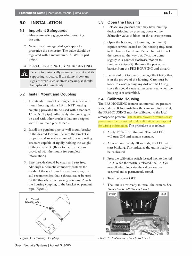
5.4 Calibrate HousingThe PRS-HOUSING features an internal low-pressuresensor alarm. Before installing the camera into the unit,the PRS-HOUSING must be calibrated to the localatmospheric pressure. The heater/blower/pressure sensorpower must be connected to do calibration. See Figure 4for wiring information. The procedure is as follows:
1. Apply POWER to the unit. The red LED will turn ON and remain constant.
2. After approximately 30 seconds, the LED willstart blinking. This indicates the unit is ready tobe calibrated.
3. Press the calibration switch located next to the redLED. When the switch is released, the LED willturn off which indicates the calibration hasoccurred and is permanently stored.
4. Turn the power OFF.
5. The unit is now ready to install the camera. SeeSection 5.6 Install Camera Module.
Add ThreadSealing Tape
Figure 1: Housing Coupling
Be sure to periodically examine the unit and itssupporting structure. If the dome shows anysigns of wear, such as stress cracking, it shouldbe replaced immediately.
Photo 1: Calibration Switch and LED
LEDSwitch
EN | 8Pressurized Dome | Instruction Manual | Installation
Bosch Security Systems | August 3, 2005
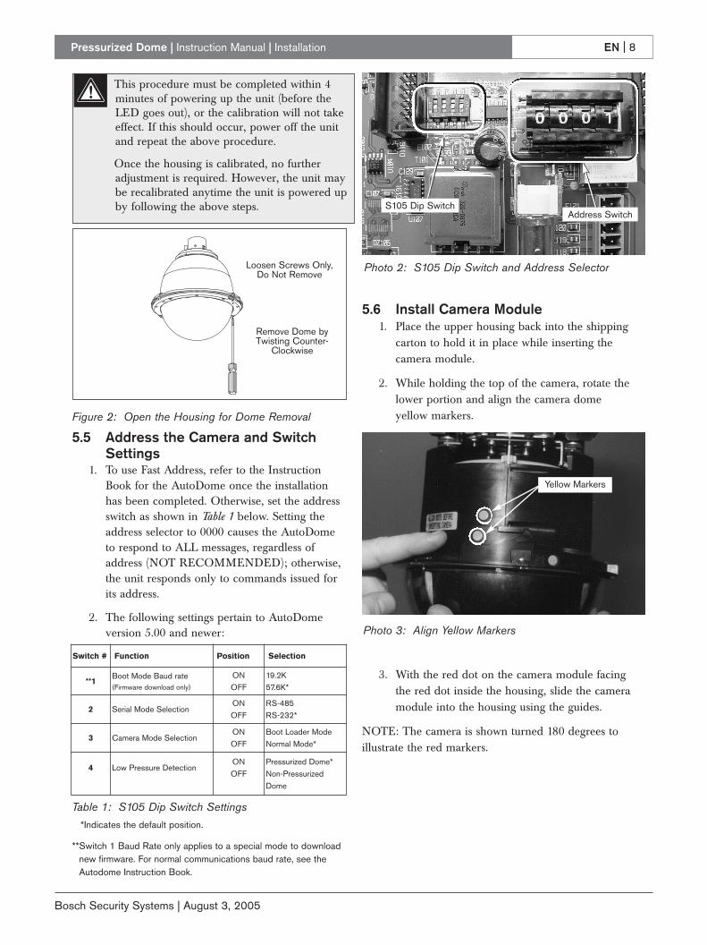
5.5 Address the Camera and SwitchSettings
1. To use Fast Address, refer to the InstructionBook for the AutoDome once the installationhas been completed. Otherwise, set the addressswitch as shown in Table 1 below. Setting theaddress selector to 0000 causes the AutoDometo respond to ALL messages, regardless ofaddress (NOT RECOMMENDED); otherwise,the unit responds only to commands issued forits address.
2. The following settings pertain to AutoDomeversion 5.00 and newer:
*Indicates the default position.
**Switch 1 Baud Rate only applies to a special mode to downloadnew firmware. For normal communications baud rate, see theAutodome Instruction Book.
5.6 Install Camera Module1. Place the upper housing back into the shipping
carton to hold it in place while inserting thecamera module.
2. While holding the top of the camera, rotate thelower portion and align the camera domeyellow markers.
3. With the red dot on the camera module facingthe red dot inside the housing, slide the cameramodule into the housing using the guides.
NOTE: The camera is shown turned 180 degrees toillustrate the red markers.
Loosen Screws Only,Do Not Remove
Remove Dome byTwisting Counter-
Clockwise
Figure 2: Open the Housing for Dome Removal
Switch # Function Position Selection
**1Boot Mode Baud rate(Firmware download only)
ONOFF
19.2K57.6K*
2 Serial Mode SelectionONOFF
RS-485RS-232*
3 Camera Mode SelectionONOFF
Boot Loader ModeNormal Mode*
4 Low Pressure DetectionONOFF
Pressurized Dome*Non-PressurizedDome
Table 1: S105 Dip Switch Settings
S105 Dip SwitchAddress Switch
Photo 2: S105 Dip Switch and Address Selector
Yellow Markers
Photo 3: Align Yellow Markers
This procedure must be completed within 4minutes of powering up the unit (before theLED goes out), or the calibration will not takeeffect. If this should occur, power off the unitand repeat the above procedure.
Once the housing is calibrated, no furtheradjustment is required. However, the unit maybe recalibrated anytime the unit is powered upby following the above steps.
Pressurized Dome | Instruction Manual | Installation EN | 9
Bosch Security Systems | August 3, 2005
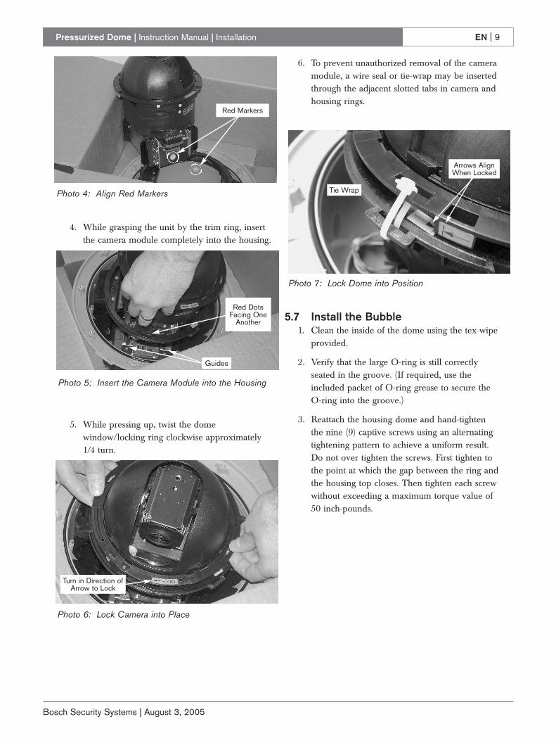
4. While grasping the unit by the trim ring, insertthe camera module completely into the housing.
5. While pressing up, twist the domewindow/locking ring clockwise approximately1/4 turn.
6. To prevent unauthorized removal of the cameramodule, a wire seal or tie-wrap may be insertedthrough the adjacent slotted tabs in camera andhousing rings.
5.7 Install the Bubble1. Clean the inside of the dome using the tex-wipe
provided.
2. Verify that the large O-ring is still correctlyseated in the groove. (If required, use theincluded packet of O-ring grease to secure theO-ring into the groove.)
3. Reattach the housing dome and hand-tightenthe nine (9) captive screws using an alternatingtightening pattern to achieve a uniform result.Do not over tighten the screws. First tighten tothe point at which the gap between the ring andthe housing top closes. Then tighten each screwwithout exceeding a maximum torque value of50 inch-pounds.
Red Markers
Photo 4: Align Red Markers
Guides
Red DotsFacing One
Another
Photo 5: Insert the Camera Module into the Housing
Turn in Direction ofArrow to Lock
Tie Wrap
Arrows AlignWhen Locked
Photo 6: Lock Camera into Place
Photo 7: Lock Dome into Position
Pressurized Dome | Instruction Manual | Installation EN | 10
Bosch Security Systems | August 3, 2005
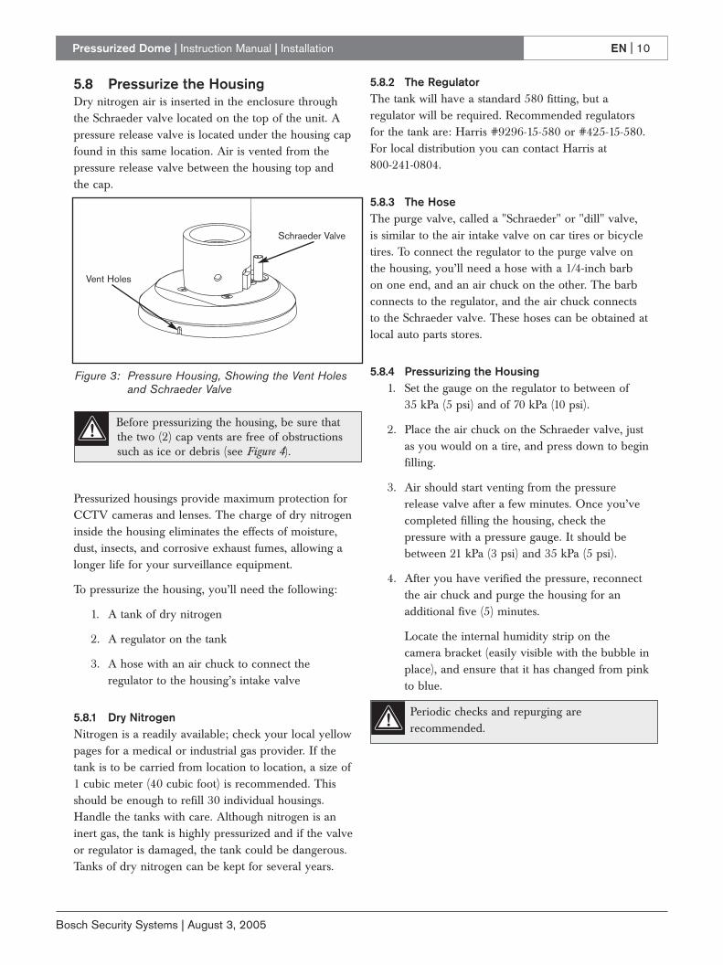
5.8 Pressurize the HousingDry nitrogen air is inserted in the enclosure throughthe Schraeder valve located on the top of the unit. Apressure release valve is located under the housing capfound in this same location. Air is vented from thepressure release valve between the housing top and the cap.
Pressurized housings provide maximum protection forCCTV cameras and lenses. The charge of dry nitrogeninside the housing eliminates the effects of moisture,dust, insects, and corrosive exhaust fumes, allowing alonger life for your surveillance equipment.
To pressurize the housing, you’ll need the following:
1. A tank of dry nitrogen
2. A regulator on the tank
3. A hose with an air chuck to connect theregulator to the housing’s intake valve
5.8.1 Dry NitrogenNitrogen is a readily available; check your local yellowpages for a medical or industrial gas provider. If thetank is to be carried from location to location, a size of1 cubic meter (40 cubic foot) is recommended. Thisshould be enough to refill 30 individual housings.Handle the tanks with care. Although nitrogen is aninert gas, the tank is highly pressurized and if the valveor regulator is damaged, the tank could be dangerous.Tanks of dry nitrogen can be kept for several years.
5.8.2 The RegulatorThe tank will have a standard 580 fitting, but aregulator will be required. Recommended regulatorsfor the tank are: Harris #9296-15-580 or #425-15-580.For local distribution you can contact Harris at 800-241-0804.
5.8.3 The HoseThe purge valve, called a "Schraeder" or "dill" valve, is similar to the air intake valve on car tires or bicycletires. To connect the regulator to the purge valve onthe housing, you’ll need a hose with a 1/4-inch barb on one end, and an air chuck on the other. The barbconnects to the regulator, and the air chuck connectsto the Schraeder valve. These hoses can be obtained atlocal auto parts stores.
5.8.4 Pressurizing the Housing1. Set the gauge on the regulator to between of
35 kPa (5 psi) and of 70 kPa (10 psi).
2. Place the air chuck on the Schraeder valve, justas you would on a tire, and press down to beginfilling.
3. Air should start venting from the pressurerelease valve after a few minutes. Once you’vecompleted filling the housing, check thepressure with a pressure gauge. It should bebetween 21 kPa (3 psi) and 35 kPa (5 psi).
4. After you have verified the pressure, reconnectthe air chuck and purge the housing for anadditional five (5) minutes.
Locate the internal humidity strip on thecamera bracket (easily visible with the bubble inplace), and ensure that it has changed from pinkto blue.
Vent Holes
Schraeder Valve
Figure 3: Pressure Housing, Showing the Vent Holesand Schraeder Valve
Before pressurizing the housing, be sure thatthe two (2) cap vents are free of obstructionssuch as ice or debris (see Figure 4).
Periodic checks and repurging arerecommended.
Pressurized Dome | Instruction Manual | Technical Reference Materials EN | 11
Bosch Security Systems | August 3, 2005
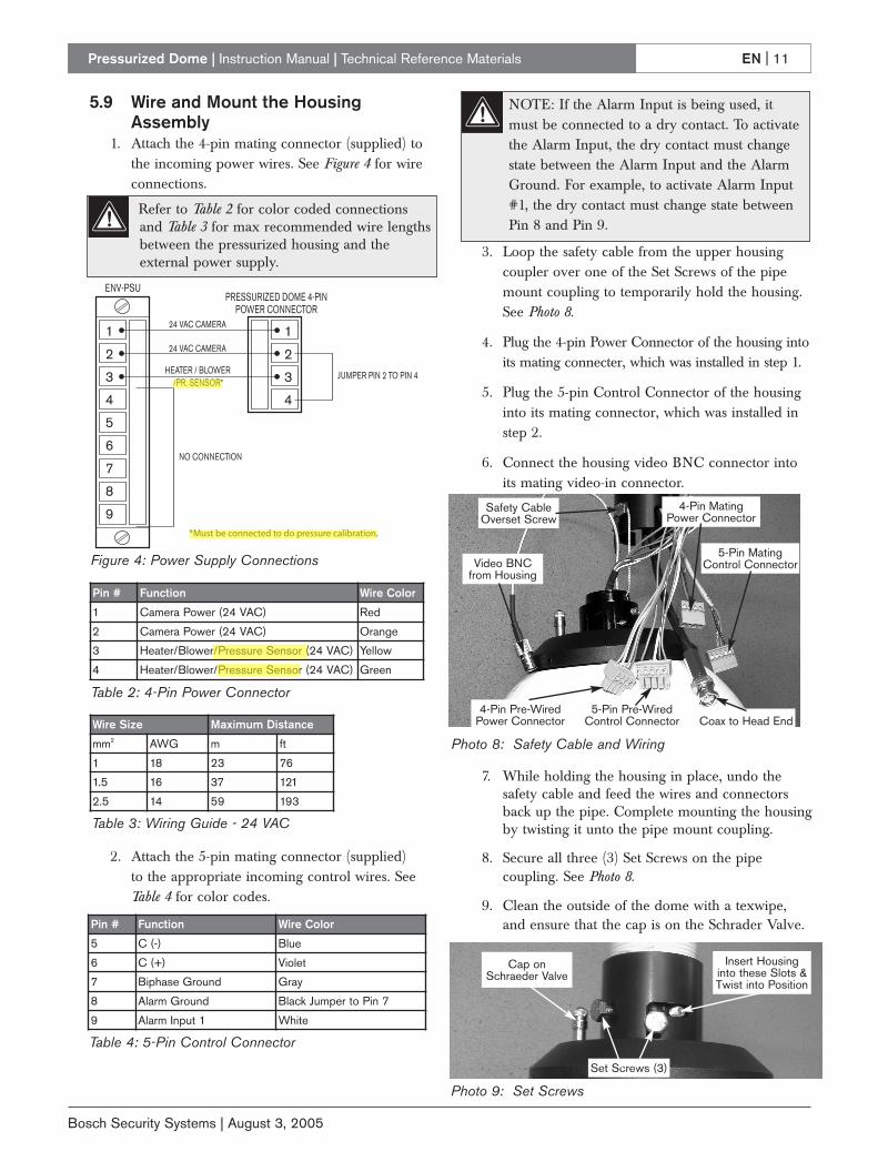
5.9 Wire and Mount the HousingAssembly
1. Attach the 4-pin mating connector (supplied) tothe incoming power wires. See Figure 4 for wireconnections.
2. Attach the 5-pin mating connector (supplied) to the appropriate incoming control wires. See Table 4 for color codes.
3. Loop the safety cable from the upper housingcoupler over one of the Set Screws of the pipemount coupling to temporarily hold the housing.See Photo 8.
4. Plug the 4-pin Power Connector of the housing intoits mating connecter, which was installed in step 1.
5. Plug the 5-pin Control Connector of the housinginto its mating connector, which was installed instep 2.
6. Connect the housing video BNC connector intoits mating video-in connector.
7. While holding the housing in place, undo thesafety cable and feed the wires and connectorsback up the pipe. Complete mounting the housingby twisting it unto the pipe mount coupling.
8. Secure all three (3) Set Screws on the pipecoupling. See Photo 8.
9. Clean the outside of the dome with a texwipe,and ensure that the cap is on the Schrader Valve.
Pin # Function Wire Color
1 Camera Power (24 VAC) Red
2 Camera Power (24 VAC) Orange
3 Heater/Blower/Pressure Sensor (24 VAC) Yellow
4 Heater/Blower/Pressure Sensor (24 VAC) Green
Pin # Function Wire Color
5 C (-) Blue
6 C (+) Violet
7 Biphase Ground Gray
8 Alarm Ground Black Jumper to Pin 7
9 Alarm Input 1 White
Video BNCfrom Housing
Safety CableOverset Screw
4-Pin Pre-WiredPower Connector Coax to Head End
5-Pin Pre-WiredControl Connector
Insert Housinginto these Slots &Twist into Position
Cap on Schraeder Valve
Set Screws (3)
5-Pin MatingControl Connector
4-Pin MatingPower Connector
1
2
3
4
5
6
7
8
9
1
2
3
4
ENV-PSUPRESSURIZED DOME 4-PIN
POWER CONNECTOR
HEATER / BLOWER/PR. SENSOR*
NO CONNECTION
JUMPER PIN 2 TO PIN 4
24 VAC CAMERA
24 VAC CAMERA
*Must be connected to do pressure calibration.
Photo 8: Safety Cable and Wiring
Photo 9: Set Screws
Wire Size Maximum Distance
mm2 AWG m ft
1 18 23 76
1.5 16 37 121
2.5 14 59 193
Table 3: Wiring Guide - 24 VAC
Figure 4: Power Supply Connections
Table 4: 5-Pin Control Connector
Table 2: 4-Pin Power Connector
Refer to Table 2 for color coded connectionsand Table 3 for max recommended wire lengthsbetween the pressurized housing and theexternal power supply.
NOTE: If the Alarm Input is being used, itmust be connected to a dry contact. To activatethe Alarm Input, the dry contact must changestate between the Alarm Input and the AlarmGround. For example, to activate Alarm Input#1, the dry contact must change state betweenPin 8 and Pin 9.
© 2005 Bosch Security Systems GmbH
F01U008442_02 05-31 | Updated August 3, 2005 | Data subject to change without notice.
AmericasBosch Security Systems130 Perinton ParkwayFairport, New York, 14450, USAPhone: +1 (585) 223 4060
+1 800 289 [email protected]://www.boschsecurity.us
Europe, Middle East, AfricaBosch Security Systems B.V.P.O. Box 800025600 JB Eindhoven, The NetherlandsPhone: +31 (0) 40 27 83955Fax: +31 (0) 40 27 [email protected]://www.boschsecurity.com
Asia-PacificBosch Security Systems Pte Ltd38C Jalan PemimpinSingapore 577180 Phone: +65 6319 3450Fax: +65 6319 3499 [email protected]://www.boschsecurity.com